1
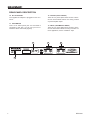
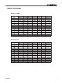
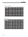
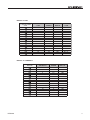
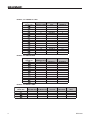
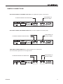
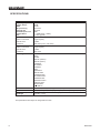
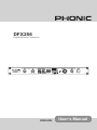
DFX256
Digital Effects Processor
DFX256
ENGLISH
User’s Manual
IMPORTANT SAFETY INSTRUCTIONS
The apparatus shall not be exposed to dripping or splashing and that no objects filled with liquids, such as vases,
shall be placed on the apparatus. The MAINS plug is used as the disconnect device, the disconnect device shall
remain readily operable.
Warning: the user shall not place this apparatus in the confined area during the operation so that the mains switch
can be easily accessible.
1. Read these instructions before operating this
apparatus.
2. Keep these instructions for future reference.
3. Heed all warnings to ensure safe operation.
4. Follow all instructions provided in this document.
5. Do not use this apparatus near water or in locations
where condensation may occur.
6. Clean only with dry cloth. Do not use aerosol or liquid
cleaners. Unplug this apparatus before cleaning.
7. Do not block any of the ventilation openings. Install
in accordance with the manufacturer’s instructions.
8. Do not install near any heat sources such as radiators,
heat registers, stoves, or other apparatus (including
amplifiers) that produce heat.
9. Do not defeat the safety purpose of the polarized or
grounding-type plug. A polarized plug has two blades
with one wider than the other. A grounding type plug
has two blades and a third grounding prong. The wide
blade or the third prong is provided for your safety. If
the provided plug does not fit into your outlet, consult
an electrician for replacement of the obsolete outlet.
10. Protect the power cord from being walked on or
pinched particularly at plug, convenience receptacles,
and the point where they exit from the apparatus.
CAUTION
RISK OF ELECTRIC SHOCK
DO NOT OPEN
CAUTION: TO REDUCE THE RISK OF ELECTRIC SHOCK,
DO NOT REMOVE COVER (OR BACK)
NO USER SERVICEABLE PARTS INSIDE
REFER SERVICING TO QUALIFIED PERSONNEL
The lightning flash with arrowhead symbol, within an
equilateral triangle, is intended to alert the user to the
presence of uninsulated “dangerous voltage” within the
product’s enclosure that may be of sufficient
magnitude to constitute a risk of electric shock to persons.
The exclamation point within an equilateral triangle is intended to alert the user to the presence of important operating and maintenance (servicing) instructions in the literature
accompanying the appliance.
WARNING: To reduce the risk of fire or electric shock, do
not expose this apparatus to rain or moisture.
CAUTION: Use of controls or adjustments or performance
of procedures other than those specified may result in
hazardous radiation exposure.
11. Only use attachments/accessories specified by the
manufacturer.
12. Use only with a cart, stand, tripod, bracket, or
table specified by the manufacturer, or sold with
the apparatus. When a cart is used, use caution
when moving the cart/apparatus
combination to avoid injury from tipover.
13. Unplug this apparatus during lighting
storms or when unused for long
periods of time.
14. Refer all servicing to qualified service personnel.
Servicing is required when the apparatus has been
damaged in any way, such as power-supply cord or
plug is damaged, liquid has been spilled or objects
have fallen into the apparatus, the apparatus has
been exposed to rain or moisture, does not operate
normally, or has been dropped.
DFX256
DFX256
Digital Effects Processor
CONTENTS
INTRODUCTION......................................................................................................................... 4
FEATURES.................................................................................................................................. 4
GETTING STARTED................................................................................................................... 4
CHANNEL SETUP.......................................................................................................................5
FRONT-PANEL DESCRIPTION...................................................................................................6
REAR-PANEL DESCRIPTION.....................................................................................................6
PRESET PROGRAMS.................................................................................................................7
SAMPLE CONNECTIONS........................................................................................................ 15
SPECIFICATIONS..................................................................................................................... 16
Phonic reserves the right to improve or alter any information suppied within this document without prior notice.
V1.1 JUN 23, 2006
DFX256
INTRODUCTION
GETTING STARTED
Congratulations on your purchase of the Phonic
DFX256 digital reverberator. The DFX256 is a high
quality and easy-to-use stereo digital reverberator.
To take full ad-vantage of the DFX256’s functions,
and enjoy a longand trouble-free use, please read
thisuser’s manualcarefully and keep it for future reference.
1. Check the AC voltage before connecting the
plug. Choose the main supply for the sound system with care. Do not share sockets or earthing
with light dimmers.
2. Run audio cables separately from dimmer wiring, using balanced lines wherever possible. If
o
necessary, cross audio and lighting cables at 90
right angles to minimize the possibility of interference. Keep unbalanced cabling as short as
possible.
3. Check your cables regularly and label each end
for easy identification.
4. Before switching on the main power, keep all
output rotary faders all the way down to prevent
damage or excessive noise caused by bad level
adjustment, wrong wiring, defective cables, or
bad connections.
5. Always turn on the DFX256 PRO before the
power amplifier; turn off the DFX256 after turning off the amplifier.
6. Always turn off the unit before connecting or disconnecting the unit to the power source.
7. Never use any solvents to clean the unit. Clean
it with a soft, dry cloth.
FEATURES
● 256 effect programs available
● Programs include reverb, delay, flanger, chorus,
tap delay, tremolo, phaser, pan effects and com●
●
●
●
●
●
●
●
binations
32-40 bit digital signal processing plus 24 bit AD/
DA conversions
True stereo reverb
Easy-to-read 3-digit LED display
Compact “1U” rack mount dimensions
Foot SW Jacks allow the user of a footswitch to
mute the effect
Auto-bypass when power is off.
Signal and clip LEDs easy setup of the optimum
input level
A professional quality digital reverb designed for
musical instruments,recording, and sound reinforcement
DFX256
FRONT-PANEL DESCRIPTION
6. OUTPUT LEVEL CONTROL
This rotary control sets the level going to the amplifier
or mixer from the output of the DFX256.
1. INPUT LEVEL CONTROL
The input level control sets the level going into the
DFX256. You should set the level so that Peak indicators only flash RED occasionally.
7. POWER SWITCH
This switch turns the power of the DFX256 on/off.
When the power is off, the DFX256 will be in signal
bypass position automatically i.e. this feature allows
the direct signal to pass through the DFX256 even
when the power is not switched on.
2. MIX (DRY / WET) CONTROL
This control sets the balance between the unaffected signal coming through the inputs and the effects
being generated by the DFX256 i.e. the balance of
wet (effect) and dry (no effect) sounds. By keeping
the Mix somewhere in the center, a blend of dry and
wet signal can be achieved.
8. SIGNAL INDICATORS
These 2 small LED indicators, located within the digital
effect display, show when either the left or right inputs
are receiving a signal (the left LED indicates when the
left input is receiving a signal, the right indicates when
the right receives a signal). When the LCD display
(above these indicators) flashes “C”, the signal in the
left or right channel is excessive (ie. clip), and should
be reduced to keep the audio’s integrity.
3. EFFECT MODES CHART
This chart shows you what 256 effect modes are in
the DFX256.
4. LED DISPLAY
This 7-segment display indicates the current effect
program in Program mode. When the display shows
the letter “C” flashing, this means either the right
or left input signals are too high and should be reduced.
9. LOAD INDICATOR
This small LED indicator, located within the digital effect display, will flash when users are previewing different effects (when turning the program select knob).
When a new program is loaded, this LED will stop
flashing.
5. PROGRAM SELECT KNOB
Turning this control will allow users to ‘preview’ the
different digital effects. Pushing it in will load the preset. If this control is not pushed within a few seconds
of changing the effect, the DFX256 will automatically
revert back to the previously loaded effect. When
this control is held down for a few seconds, the digital effects b will be bypassed. Holding it down again
will reactivate the effects. When selecting the Tap
Delay effect (T1 - T6), pushing the Program Select
control will allow users to adjust the delay time. The
time between the final two presses will be calculated
and used as the delay time.
2
4
DFX256
5
6
7
9
REAR-PANEL DESCRIPTION
10. AC 10V IN INLET
The supplied AC Adapter is plugged into this connector.
11. FOOTSWITCH
This is a 1/4” stereo phone jack. If a foot switch is
connected to this jack, you can use your foot to
switch the effect mute on/off (bypass).
12. OUTPUT (LEFT & RIGHT)
There are 1/4” phone jacks which connect to devices such as the effects returns on a mixing console
or power amplifier inputs.
13. INPUT (LEFT/MONO & RIGHT)
There are 1/4” phone jacks which connect to sources such as the effects sends of mixing consoles. For
mono application, use the “Left/Mono” input.
2
0
DFX256
PRESET PROGRAMS
PRESET
PROGRAMS
EFFECT 1: ROOM
7 Segment LED
Room
1
2
3
4
5
6
7
8
9
10
11
12
13
14
15
16
ROOM
1
2
3
4
5
6
7
8
9
10
11
12
13
14
15
16
REV-T I M E P RED EL AY H I - RAT I O
0. 05
40
0. 5
0. 05
0
0. 6
0. 4
0
0. 95
0. 4
0
0. 93
0. 45
5
0. 95
0. 45
30
0. 9
0.6
0
0. 9
0.6
6
0. 92
0. 65
22
1
0. 9
6
0. 96
1
1
10
1. 2
15
0. 98
1. 4
0. 98
60
0
1. 4
0. 96
1
1. 6
22
3. 85
0. 96
25
HPF
80
0
382
430
500
0
550
0
0
0
500
410
0
22
0
0
L PF
2. 5K
1. 8K
9K
1. 25K
12. 5K
6.3K
2.36K
5.6K
19 K
8K
20 K
9. 5K
5. 6K
6. 7K
10. 6K
4.75K
D RY/ W ET
0~100
0~100
0~100
0~100
0~100
0~100
0~100
0~100
0~100
0~100
0~100
0~100
0~100
0~100
0~100
0~100
REV -T I M E PRED ELA Y H I - RAT I O
0. 9
0
0. 9
20
0. 95
1
1. 9 5
40
0. 98
1. 7 5
48
0. 98
1. 8
20
0. 83
1. 8 5
40
0. 95
1. 9
30
0. 98
2. 2
25
0. 99
100
0. 7
2. 3
2 .4 5
30
0. 95
2 .5
0. 8
40
2. 5
0
4
2. 7
1
85
2. 7
0. 85
20
2. 8
0. 97
40
3. 3
0. 85
75
H PF
0
26
0
0
0
340
675
0
0
25
85
75
40
0
0
63
L PF
9K
10. 6K
15 k
9. 5K
4.25K
7. 1K
8. 5K
2.24K
6. 7K
8. 5K
12. 5K
3.15K
12. 5K
8K
8. 5K
10K
D RY/ W ET
0~ 100
0~ 100
0~ 100
0~ 100
0~ 100
0~ 100
0~ 100
0~ 100
0~ 100
0~ 100
0~ 100
0~ 100
0~ 100
0~ 100
0~ 100
0~ 100
EFFECT 2: HALL
7 Segment LED
Hall
17
18
19
20
21
22
23
24
25
26
27
28
29
30
31
32
DFX256
HA L L
1
2
3
4
5
6
7
8
9
10
11
12
13
14
15
16
EFFECT 3: PLATE
7 Segment LED
Plate
33
34
35
36
37
38
39
40
41
42
43
44
45
46
47
48
PLATE
1
2
3
4
5
6
7
8
9
10
11
12
13
14
15
16
REV-T I M E P RED EL AY H I -RAT I O
0. 55
0
1
0. 55
0
1
0. 75
20
1
0. 9
12
0. 98
1
10
1
1. 2
25
1
35
1
1. 3
1. 8
30
0. 98
2
1
1
1
2. 25
25
2. 6
180
0. 97
2. 75
30
0. 98
3
0
1
5
0. 99
3
0. 98
3. 35
1
3.8
20
0. 85
HPF
625
625
0
0
0
20
0
80
67
42
0
0
625
0
0
0
L PF
20K
20K
12.5K
12.5K
10.6K
7.1K
20K
12.5K
20K
20K
15K
4. 25K
20K
8K
16K
1.4K
D RY/ W ET
0~1 00
0~1 00
0~1 00
0~1 00
0~1 00
0~1 00
0~1 00
0~1 00
0~1 00
0~1 00
0~1 00
0~1 00
0~1 00
0~1 00
0~1 00
0~1 00
EFFECT 4: DELAY-1 (ST)
7 Segment LED
Delay-1(ST)
49
50
51
52
53
54
55
56
57
58
59
60
61
62
63
64
DELAY-1(stereo)
1
2
3
4
5
6
7
8
9
10
11
12
13
14
15
16
L- D EL AY
0.16
0.16
0.16
0.16
0.16
0.16
0.16
0.52
0.6
0.6
0.8
0.21
0.14
0.25
0.03
0.3
R-D EL A Y
0.03
0.08
0.08
0
0
0
0
0.2
0.2
0.2
0.3
0.2
0.05
0.05
0.06
0.06
C- D EL A Y
0.03
0.16
0
0.18
0.16
0.16
0.16
0.5
0.6
0.6
0.5
0.2
0.16
0
0.06
0
FB -D EL A Y
0. 04
0
0
0
0. 14
0. 2
0. 21
0. 3
0. 4
0. 4
0. 7
0. 1
0.16
0. 5
0. 05
0. 6
DFX256
EFFECT 5: DEALY-2 (MONO)
7 Segment LED
Delay-2(MONO)
65
66
67
68
69
70
71
72
73
74
75
76
77
78
79
80
DEL AY-2(mono)
1
2
3
4
5
6
7
8
9
10
11
12
13
14
15
16
L - D EL AY
0
0
0
0
0
0
0
0
0
0
0
0
0
0
0
0
R-D ELAY
0
0
0
0
0
0
0
0
0
0
0
0
0
0
0
0
C-D ELAY
0. 5
0. 5
0. 15
0. 15
0. 15
0. 2
0. 2
0. 4
0
0
0
0
1. 2
1. 2
0. 5
0. 15
FB - D ELAY
0. 3
0. 3
0. 1
0. 03
0. 15
0. 3
0. 2
0. 4
0. 3
0. 4
0. 4
0. 55
1
1. 2
1
0. 4
PH A SE
180
180
0
0
180
180
180
0
180
0
180
180
0
180
0
180
L PF
7.1 K
6K
8K
6. 3 K
10K
500
8K
1. 2 5K
10 K
1K
10 K
50 0
10 K
85 0
10 K
10 K
EFFECT 6: CHORUS
7 Segment LED
Chorus
81
82
83
84
85
86
87
88
89
90
91
92
93
94
95
96
DFX256
CHORUS
1
2
3
4
5
6
7
8
9
10
11
12
13
14
15
16
L FO
0. 3
0. 8
1. 2
1. 8
2. 2
3. 6
3. 2
4
5. 6
6. 4
7. 5
7. 8
8. 4
8. 8
9. 2
10
P E R-D EL AY
2
5
20
1
60
15
30
90
120
200
88
80
50
10
5
115
EFFECT 7: FLANGER
7 Segment LED
Flanger
97
98
99
100
101
102
103
104
105
106
107
108
109
110
111
112
FL ANGER
1
2
3
4
5
6
7
8
9
10
11
12
13
14
15
16
LFO
0.1
0.3
0.6
0.7
1
1
1.6
1.6
2
2
2
2.6
2.8
2.8
4.6
4.6
PER-D EL AY
2
6
10
15
1
10
20
20
1
2
2
2
6
4
2
4
P H AS E
180
0
180
180
180
180
180
180
180
180
180
180
180
180
180
180
PHASER
1
2
3
4
5
6
7
8
9
10
11
12
13
14
15
16
LFO
0. 1
0. 4
0. 8
1. 4
2. 2
2. 6
3. 3
4
4. 8
5. 2
5. 8
6
6
7. 2
7. 8
10
D EL AY
3. 5
0. 6
3. 2
0. 6
1. 6
4
1
2. 8
1
0. 1
0. 8
1. 2
3. 2
5
2. 6
5
P H AS E
180
90
180
180
180
180
180
180
180
180
180
90
180
180
180
180
EFFECT 8: PHASER
7 Segment LED
Phaser
113
114
115
116
117
118
119
120
121
122
123
124
125
126
127
128
10
DFX256
EFFECT 9: PAN
7 Segment LED
Pan
129
130
131
132
133
134
135
136
137
138
139
140
141
142
143
144
PAN
1
2
3
4
5
6
7
8
9
10
11
12
13
14
15
16
SPE E D
0.1
0.4
0.8
1.2
0.1
0.4
0.8
1.2
0.1
0.4
0.8
1.2
1.8
1.8
1.8
3.4
D EPT H
100
100
100
100
100
100
100
100
100
100
100
100
100
100
100
100
T YP E
L --> R
L --> R
L --> R
L --> R
R--> L
R--> L
R--> L
R--> L
R<--> L
R<--> L
R<--> L
R<--> L
L --> R
R--> L
R<--> L
R<--> L
EFFECT 10: TREMOLO
7 Segment LED
Tremolo
145
146
147
148
149
150
151
152
153
154
155
156
157
158
159
160
DFX256
TREMOLO
1
2
3
4
5
6
7
8
9
10
11
12
13
14
15
16
SPE E D
0. 5
0. 8
1
1. 2
1. 6
2
2. 4
3
3. 4
4
4. 4
5. 2
6
6. 6
8
10
D E PT H
100
100
100
100
100
100
100
100
100
100
100
100
100
100
100
100
11
EFFECT 11: DELAY + REV
7 Segment LED
Delay+Rev
161
162
163
164
165
166
167
168
169
170
171
172
173
174
175
176
DELAY+REV
1
2
3
4
5
6
7
8
9
10
11
12
13
14
15
16
D E L AY- 1
1
2
3
4
5
6
7
8
9
10
11
12
13
14
15
16
REV
ROOM 1
ROOM 7
RO O M 11
RO O M 12
RO O M 14
RO O M 15
H A LL 1
H A LL 3
H A LL 6
H A L L11
H A L L15
H A L L16
PLA T 1
PLA T 3
PLA T 6
PL A T12
CH ORU S
1
2
3
4
5
6
7
8
9
10
11
12
13
14
15
16
REV
ROOM 1
ROOM 7
RO O M 11
RO O M 12
RO O M 14
RO O M 15
H A LL 1
H A LL 3
H A LL 6
H A L L11
H A L L15
H A L L16
PLA T 1
PLA T 3
PLA T 6
PL A T12
EFFECT 12: CHORUS + REV
7 Segment LED
Chorus+Rev
177
178
179
180
181
182
183
184
185
186
187
188
189
190
191
192
12
CHORUS+REV
1
2
3
4
5
6
7
8
9
10
11
12
13
14
15
16
DFX256
EFFECT 13: FLANGER + REV
7 Segment LED
Flanger+Rev
193
194
195
196
197
198
199
200
201
202
203
204
205
206
207
208
FLANGER+REV
1
2
3
4
5
6
7
8
9
10
11
12
13
14
15
16
FL A N GER
1
2
3
4
5
6
7
8
9
10
11
12
13
14
15
16
REV
ROO M 1
ROO M 7
ROO M11
ROO M12
ROO M14
ROO M15
H AL L 1
H AL L 3
H AL L 6
H A L L11
H A L L15
H A L L16
PLA T 1
PLA T 3
PLA T 6
PL A T 12
PH ASER
1
2
3
4
5
6
7
8
9
10
11
12
13
14
15
16
REV
ROO M 1
ROO M 7
ROO M11
ROO M12
ROO M14
ROO M15
H AL L 1
H AL L 3
H AL L 6
H A L L11
H A L L15
H A L L16
PLA T 1
PLA T 3
PLA T 6
PL A T 12
EFFECT 14: PHASER + REV
7 Segment LED
Phaser+Rev
209
210
211
212
213
214
215
216
217
218
219
220
221
222
223
224
DFX256
PHASER+REV
1
2
3
4
5
6
7
8
9
10
11
12
13
14
15
16
13
EFFECT 15: TREMOLO + REV
7 Segment LED
Tremolo+Rev
225
226
227
228
229
230
231
232
233
234
235
236
237
238
239
240
TREMOLO+REV
1
2
3
4
5
6
7
8
9
10
11
12
13
14
15
16
REV
ROOM 1
ROOM 7
ROOM11
ROOM12
ROOM14
ROOM15
H AL L 1
H AL L 3
H AL L 6
H ALL11
H ALL15
H ALL16
PLATE 1
PLATE 3
PLATE 6
PLATE 12
T REMOLO
1
2
3
4
5
6
7
8
9
10
11
12
13
14
15
16
EFFECT 16: SPECIAL EFX
7 Segment LED
Special efx
241
242
243
244
245
246
247
248
249
250
251
252
SPECI AL EFX
1
2
3
4
5
6
7
8
9
10
11
12
DELAY-1-1
FLAN GE- 3
DELAY-1-1
CHORUS- 4
D EL A Y- 1- 1
PH ASER- 7
CH ORU S- 2
FL A N G E- 1
PH ASER-10
CH ORU S- 5
TREMOLO - 6
FLANGE-11
TREMOLO-12 CH ORU S- 4
PH ASER- 5
FL AN GE- 9
PH ASER- 5 T REMOLO-12
FL A N G E- 1
TREMOLO- 6
PH A SE R- 7
PAN - 2
FLA N GE- 3
PA N - 2
EFFECT 17: GATED + REV
7 Segment LED
Gated+Rev
253
254
255
256
14
GATED-REV T H RESH O LD
1
-20
2
-20
3
-20
4
-20
AT TACK
0
0
0
200
REL EASE
0.02
0.5
0.1
0.01
REV
PLAT- 1
PLAT- 8
H A LL-15
H A LL-16
DFX256
SAMPLE CONNECTIONS
SAMPLE CONNECTIONS
ONE MONO CORD IN, ONE MONO CORD OUT (to an amplification system or mixer input)
TO MIXING CONSOLE OR AMPLIFIER
INSTRUMENT OF
EFFECTS SEND
ONE MONO CORD IN, TWO MONO CORDS OUT (to a stereo amplifier or two mixer inputs)
TO MIXING CONSOLE OR AMPLIFIER
INSTRUMENT OF
EFFECTS SEND
TWO MONO CORDS IN AND OUT (to a stereo amplifier or two mixer inputs)
This can be stereo signal in/out or mono signal in/out.
TO MIXING CONSOLE OR AMPLIFIER
DFX256
INSTRUMENT OF
EFFECTS SEND
15
SPECIFICATIONS
Frequency Response
Dynamic Range
AD/DA
DSP processing
Sampling rate
Maximum Input Level
Residual Noise
T.H.D.
Input
Number of Channel:
Nominal Level:
Impedance:
20Hz ~ 20kHz
90dB
24-bit
32~40-bit
44.1kHz
0dB
< -80dB (20Hz ~ 20kHz)
< .05% (typical)
DFX256
2 (phone jack)
-20dB
20k ohms (mono: 10k ohms)
Output
Number of Channel:
Nominal Level:
Impedance:
Effect Programs
2 (phone jack)
-20dB
600 ohms
Front Panel Controls
Real Panel Jack
Dimensions (WxHxD)
Net Weight
Input level, Mix-dry/wet, Program select, Output level, Power Sw.
2 Input phone jacks, 2 Output phone jacks, foot Sw- phone jack, DC jack
19"x1.75"x4.2" / 483 x 44 x 107mm (1U)
2.64 lbs / 1.2 kg
ROOM
HALL
PLATE
DELAY-1(stereo)
DELAY-2(mono)
CHORUS
FLANGER
PHASER
PAN
TREMOLO
DELAY+REV
CHORUS+REV
FLANGER+REV
PHASER+REV
TREMOLO+REV
SPECIAL EFX
GATED-REV
TAP DELAY
The specifications are subject to change without notice.
16
DFX256
6103 Johns Road #7
18
DFX256