1
s
Contents
Definitions
1
Product description
2
Mounting
3
Configuring
4
ESD guidelines
5
SIMADYN D
Application Module FM 458
User Manual
Order No.: 6DD1904-0AE0
Safety guidelines
This Manual contains notices which you should observe to ensure your own personal
safety, as well as to protect the product and connected equipment. These notices are
highlighted in the Manual by a warning triangle and are marked as follows according to
the level of danger:
!
DANGER
indicates an imminently hazardous situation which, if not avoided, will result in death or
serious injury.
!
WARNING
indicates a potentially hazardous situation which, if not avoided, could result in death or
serious injury.
!
CAUTION
used with the safety alert symbol indicates a potentially hazardous situation which, if not
avoided, may result in minor or moderate injury.
CAUTION
used without safety alert symbol indicates a potentially hazardous situation which, if not
avoided, may result in property damage.
NOTICE
used without the safety alert symbol indicates a potential situation which, if not avoided,
may result in an undesireable result or state.
Correct usage
Note the following:
This device and its components may only be used for the applications described in the
catalog or the technical description, and only in connection with devices or components
from other manufacturers which have been approved or recommended by Siemens.
Trademarks
SIMATIC and SIMADYN D are registered trademarks of Siemens AG.
Third parties using for their own purposes any other names in this document which refer
to trademarks might infringe upon the rights of the trademark owners.
Copyright SIEMENS AG 2002 All rights reserved
Disclaimer of liability
The reproduction, transmission or use of this document or its
contents is not permitted without express written authority.
Offenders will be liable for damages. All rights, including rights
created by patent grant or registration of a utility model or
design, are reserved.
We have checked the contents of this manual for agreement
with the hardware and software described. Since deviations
cannot be precluded entirely, we cannot guarantee full
agreement. However, the data in this manual are reviewed
regularly and any necessary corrections included in subsequent
editions. Suggestions for improvement are welcomed.
Siemens AG
A&D AS CC DC
Frauenauracher Straße 80
91056 Erlangen
Siemens Aktiengesellschaft
Siemens AG 2002
Technical data subject to change.
MLFB-Nr. 6DD1987-1AB4
Contents
1
Definitions .............................................................................................1-1
2
Product description ..............................................................................2-1
2.1
2.1.1
2.1.2
2.1.3
2.1.4
2.1.5
2.1.6
2.2
2.2.1
2.2.2
2.2.3
2.2.4
2.2.5
2.2.6
2.3
2.3.1
2.3.2
2.3.3
2.3.4
2.3.5
2.3.6
2.4
2.4.1
2.4.2
2.4.3
2.4.4
2.1.5
2.1.6
2.1.7
3
Application module FM 458 ....................................................................2-1
Application and design ............................................................................2-1
Performance features .............................................................................2-4
Supplementary components ...................................................................2-5
Connections ............................................................................................2-6
Status displays ........................................................................................2-8
Technical data.........................................................................................2-9
I/O expansion module EXM 438 ..........................................................2-10
Application and design ..........................................................................2-10
Performance features ...........................................................................2-11
Supplementary components .................................................................2-12
Connection possibilities ........................................................................2-13
Incremental encoder settings................................................................2-20
Technical data.......................................................................................2-21
I/O expansion module EXM 438-1 .......................................................2-25
Application and design ..........................................................................2-25
Performance features ...........................................................................2-26
Supplementary components .................................................................2-26
Connection possibilities ........................................................................2-26
Incremental encoder settings................................................................2-27
Technical data.......................................................................................2-28
Communications expansion module EXM 448 .....................................2-30
Application and design ..........................................................................2-30
Performance features ...........................................................................2-31
Supplementary components .................................................................2-32
Installing the option module ..................................................................2-32
Connection possibilities ........................................................................2-34
Status displays ......................................................................................2-36
Technical data.......................................................................................2-36
Mounting................................................................................................3-1
3.1
3.2
3.3
Mounting the expansion modules ...........................................................3-1
Installing the assembly into the SIMATIC subrack..................................3-7
Application information and noise immunity............................................3-8
4
Configuring............................................................................................4-1
4.1
4.2
4.3
4.3.1
4.3.2
4.3.3
4.3.4
Freely configuring the FM 458 application module .................................4-1
Configuring and parameterizing the components ...................................4-2
Coupling to the SIMATIC S7-CPU ..........................................................4-5
Overview of the 3 data transfer types, FM 458 ←→ SIMATIC-CPU ......4-6
Initiating a process interrupt on SIMATIC-CPU ......................................4-7
Data transfer via I/O accesses................................................................4-8
Transferring data sets ...........................................................................4-11
Application Module FM 458 - User Manual
6DD1904-0AE0 Edition 02.2002
iii
Contents
4.4
4.4.1
4.4.2
4.4.3
4.4.4
4.4.4.1
4.4.4.2
4.4.4.3
4.4.5
4.4.6
4.5
4.5.1
4.5.1.1
4.5.1.2
4.5.1.3
4.5.2
4.5.2.1
4.5.2.2
4.5.3
4.5.3.1
4.5.3.2
4.5.3.3
4.5.3.3.1
4.5.3.3.2
4.5.3.3.3
4.5.3.4
4.5.4
4.5.4.1
4.5.4.2
4.5.4.3
4.5.4.4
4.6
4.6.1
4.6.1.1
4.6.1.2
4.6.1.3
4.6.1.4
4.6.1.5
4.6.2
4.6.2.1
4.6.2.2
4.6.2.3
4.6.2.4
4.6.2.5
5
ESD guidelines ......................................................................................5-1
5.1
5.1.1
5.1.2
5.1.3
iv
SIMOLINK drive coupling......................................................................4-14
Basic information ..................................................................................4-14
Application with master-slave process data transfer.............................4-16
Applications and modes which should be set .......................................4-17
Configuring - first steps .........................................................................4-21
Configuring the SIMOLINK coupling under STEP 7..............................4-21
SIMOLINK function blocks ....................................................................4-26
Parameterizing the MASTERDRIVES MC ............................................4-27
Coupling diagnostics .............................................................................4-29
Options and accessories.......................................................................4-31
Table function........................................................................................4-32
Introduction ...........................................................................................4-32
Overview, "Manual mode".....................................................................4-33
Overview, "Automatic mode: Communications"....................................4-33
Function block WR_TAB.......................................................................4-35
Manual mode ........................................................................................4-38
Application.............................................................................................4-38
Configuring............................................................................................4-39
Automatic mode: Communications .......................................................4-40
Application with an S7 control and SIMATIC FM 458 application module4-40
Configuring for S7 control and SIMATIC FM 458 application module ..4-42
Inserting tabular values in the data block..............................................4-43
Manually entering tabular values...........................................................4-43
Importing tabular values........................................................................4-47
Subsequently downloading tabular values into a DB ............................4-57
Structure of the data telegram for TCP/IP or DUST1 connection .........4-59
Automatic mode: Memory card .............................................................4-60
Generating a table file in the csv format ...............................................4-60
Working with the D7-SYS additionalComponentBuilder .......................4-62
Downloading .........................................................................................4-65
Configuring the function blocks.............................................................4-67
Parameter access technique for D7-SYS .............................................4-69
General description of the parameter functionalityinformation..............4-69
Parameters ...........................................................................................4-69
BICO technology for SIMADYN D.........................................................4-72
Status-dependent parameter changes..................................................4-76
Identifying SIMADYN D components ....................................................4-77
Units and unit texts................................................................................4-78
Parameterizing on the Application module FM 458 ..............................4-81
Terminology ..........................................................................................4-81
Communications behavior ....................................................................4-81
Generating the hardware configuration.................................................4-82
Functional scope ...................................................................................4-82
Operator devices which can be connected ...........................................4-83
What does ESD mean? ..........................................................................5-1
Handling ESD boards..............................................................................5-2
Measuring and modifying ESD boards....................................................5-2
Shipping ESD boards..............................................................................5-3
Application Module FM 458 - User Manual
6DD1904-0AE0 Edition 02.2002
1 Definitions
General
information
1
These Operating Instructions do not contain all of the detailed information
for all product types for reasons of transparency. This means that they
cannot take into account all conceivable situations regarding the
configuration, operation or service. If you require additional information, or
if specific problems occur, which are not handled in sufficient detail in the
Operating Instructions, then you can request the necessary information
from your local Siemens Office.
We would also like to point-out, that the contents of the operating
instructions are neither part of an earlier or existing agreement, statement
or legal relationship, nor do they change this. All of the contractual
responsibilities of Siemens AG are specified in the purchase contract
which includes the complete and exclusively valid warranty. The
contractual warranty is neither expanded nor restricted by the information
provided in these Operating Instructions.
Qualified personnel
For the purpose of these Operating Instructions and product labels, a
„Qualified person“ is someone who is familiar with the installation,
mounting, start-up and operation of the equipment and the hazards
involved. He or she must have the following qualifications:
1. Trained and authorized to energize, de-energize, clear, ground and tag
circuits and equipment in accordance with established safety
procedures.
2. Trained in the proper care and use of protective equipment in
accordance with established safety procedures.
3. Trained in rendering first aid
CAUTION
The boards contain components which can be destroyed by
electrostatic discharge. Prior to touching any electronics board, your
body must be electrically discharged. This can be simply done by
touching a conductive, grounded object immediately beforehand (e.g.
bare metal cabinet components, socket protective conductor contact).
Application Module FM 458 - User Manual
6DD1904-0AE0 Edition 12.2001
1-1
Definitions
1-2
Application Module FM 458 - User Manual
6DD1904-0AE0 Edition 12.2001
2
Product description
2.1
Application module FM 458
Designation
Application module FM 458
2
Order No.
6DD1607-0AA0
2.1.1 Application and design
Application
The FM 458 (Function Module) application module is an application
module which can be graphically freely configured and which can be used
for sophisticated high-dynamic performance open-loop and closed-loop
control functions. It is designed for use in a SIMATIC S7-400 station as a
passive node which is connected to the SIMATIC backplane buses
(P bus and K bus).
Applications include higher-level closed-loop drive controls for:
• Closed-loop tension control
• Closed-loop position control
• Winders and coilers
• Angular and synchronous controls
• Positioning
• Cross-cutters and flying saws
• Other closed-loop controls
Expansion
modules
Designation
Order No.
Input/output expansion module EXM 438
6DD 1607-0CA0
Input/output expansion module EXM 438-1
6DD 1607-0CA1
Communications expansion module EXM 448
6DD 1607-0EA0
As the FM 458 is a passive node on the backplane bus, the S7-CPU
module must read-in signals from the SIMATIC I/O, and send these to the
FM 458. The FM can be supplemented by the following expansion
modules for fast process coupling:
• The I/O expansion module EXM 438/EXM 438-1 provides additional
digital and analog I/O as well as incremental and absolute value
encoders.
Application Module FM 458 - User Manual
6DD1904-0AE0 Edition 12.2001
2-1
Product description
• Communications via PROFIBUS-DP (master or slave) is realized
using the EXM 448 communications expansion module. Optionally,
MASTERDRIVES-plug-in modules, e.g. SLB for SIMOLINK, can
increase their functionality.
A maximum of two expansion modules can be used together with the
FM 458 application module. The following combinations are possible:
Application module
FM 458
Table 2-1
NOTE
st
1 expansion module
2
nd
expansion module
None
None
EXM 438 or EXM 438-1
None
EXM 448
None
EXM 438 or EXM 438-1
EXM 438 or EXM 438-1
EXM 448
EXM 448
EXM 438 or EXM 438-1
EXM 448
EXM 448
EXM 438 or EXM 438-1
Possibilities of combining expansion modules
When configuring the system, please note that the maximum load
capability of the S7 power supply module may not be exceeded as a
result of the current drawn by the FM 458 module.
When using an IM module, which is also used to transfer power to other
modules, its maximum load capability must also be observed.
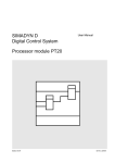
Fig. 2-1
2-2
View of the FM 458 application module with two expansion modules
Application Module FM 458 - User Manual
6DD1904-0AE0 Edition 12.2001
Product description
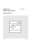
Design
8 x LED
INTF
IF
2
UF
MF
CF
TF
RUN
STOP
SIMATIC P-BUS
Acknowledge button
Slot for the
program memory modules,
e.g. MC 521
SIMATIC P-BUS
X1 RS 232 interface
Fig. 2-2
K-BUS
LE-BUS
X2
8 digital inputs
Mechanical design of the FM 458 application module
Application Module FM 458 - User Manual
6DD1904-0AE0 Edition 12.2001
2-3
Product description
2.1.2 Performance features
The FM 458 application module has the high-performance processor core
of the PM6 SIMADYN D CPU module and has the following performance
features:
• Computational performance
− 128 MHz, 64 bit RISC floating-point-processor
− fastest cycle times of 0.1 ms, typical 0.5 ms
• DRAM (8 MB)
− Program code is loaded when the memory module is loaded and
expanded when the memory module is initialized (boot flash is
provided separately)
− Data memory for the operating system, communications, message
buffer, trace
• SRAM (256 KB)
The buffered SRAM contains the following data, which should be
saved (non-volatile) even when the power fails:
− Error diagnostics of the operating system ("exception buffer")
− max. 1000 process quantities, configured using the SAV function
block
− Data, traced using the message system or trace function
(optional SRAM configuring)
• Replaceable program memories
− MC 521 mit 2 MB Flash EPROM und 8 kByte EEPROM
− MC 500 mit 4 MB Flash EPROM und 8 kByte EEPROM
• Two interfaces are available to load the user program into the program
memory:
− via a PCMCIA-IPC card slot (load offline)
− directly from the PC via the serial service interface (loading online)
• 8 interrupt tasks can be called via 8 digital inputs.
• RS-232 interface (V.24) with service protocol DUST1 (19.2 kBd) for:
−
CFC test mode (incl. download)
− "Service/IBS“/TELEMASTER [IBS = Start-up]
• 8 LEDs to display the operating status
2-4
Application Module FM 458 - User Manual
6DD1904-0AE0 Edition 12.2001
Product description
• Acknowledge button
Sporadically occurring faults (TF) or non-critical faults (MF) can be
cancelled in the LED dispoay using the acknowledge button.
If another fault/error exists, then it is displayed after the first has been
acknowledged.
• LE bus
The LE bus ensures fast data transfer between the FM 458 application
module and its expansion modules EXM 438/EXM 438-1/EXM 448.
• P bus
The peripheral (I/O) bus (P bus) is the parallel SIMATIC backplane
bus which is designed for fast I/O signal transfer. Each SIMATIC
subrack has a P bus.
2.1.3 Supplementary components
Components
Designation
Order No.
Program memory
MC 521
6DD1610-0AH3
Program memory
MC 500
6DD1610-0AH4
Cable for PC connection
(9-pin/9-pin)
SC57
6DD1684-0FH0
Cable for digital inputs
(9-pin/10-pin)
SC64
6DD1684-0GE0
Interface module
SU12
6DD1681-0AJ1
Interface module
SB10
6DD1681-0AE2
Interface module
SB60
6DD1681-0AF4
Interface module
SB61
6DD1681-0EB3
Table 2-2
Application Module FM 458 - User Manual
6DD1904-0AE0 Edition 12.2001
Supplementary components for the FM 458 application module
2-5
2
Product description
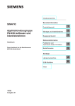
2.1.4 Connections
SIMATIC P-BUS
FM 458
Operator control unit
SIMATIC P-BUS
X1
Serial interface
(service)
SC57 (Partial connector 1)
each 9 pin
l=5 m
X2
8 digital inputs
9pol.
SC64 (9 pin/10 pin)
8 DI
l=2 m
LE-BUS
K-BUS
9pol.
SB10
SB60
SB61
or
Interface modules
SU12
Fig. 2-3
An operator control or configuring-PC is connected to the 9-pin sub-D
socket via the SC57 PC cable.
Serial service
interface (X1)
5
9
1
6
PIN
X1
Designation
1
2
3
4
5
6
7
8
9
Receive Data In
Transmit Data Out
Ground 0V
Request to Send
Clear to Send
-
Table 2-3
2-6
Possibilities of connecting the FM 458 application module
SC57
PIN
PIN
FM-side
PC-side
2
3
3
2
5
5
Connection assignment of X1 and SC57 cable
Application Module FM 458 - User Manual
6DD1904-0AE0 Edition 12.2001
Product description
Digital inputs (X2)
5
9
1
6
The digital inputs are connected at the 9-pin sub-D socket via cable
SC64.
PIN
Designation
1
Interrupt input 1
2
Interrupt input 3
3
Interrupt input 5
4
Interrupt input 7
5
Ground
6
Interrupt input 2
7
Interrupt input 4
8
Interrupt input 6
9
Interrupt input 8
Table 2-4
2
Connector assignment of X2
LE-bus connection
An expansion module (EXM 438/EXM 438-1 or EXM 448) can be inserted
at this 5 x 24-pin socket connector.
P-bus connection
Two 5 x 17-pin socket connectors are used to connect to the SIMATIC S7
backplane bus.
K-bus connection
A 5 x 7-pin socket connector is provided for connection to
the SIMATIC K bus.
Interface modules
The screw terminals for the digital inputs are available via the interface
modules.
Interface modules
Function
SB10, SU12
Electrical 1:1 connection, no signal conversion
SB60, SB61
With electrical isolation and signal conversion
Refer to Catalog DA 99 for information on the interface modules.
Application Module FM 458 - User Manual
6DD1904-0AE0 Edition 12.2001
2-7
Product description
2.1.5 Status displays
There are eight LED displays on the front panel of the FM 458. They
provide information about its actual operating status and data for
diagnostics.
LED
Color
Status
Significance
INTF
red
lit
Internal error, user program is not running
IF
red
lit
Initialization error
For errors, which occur when initializing the system, the user program
doesn't start. Initialization errors due to incorrect modules or modules
which are incorrectly inserted with respect to how they were originally
configured.
UF
yellow
lit
User error
The user program runs, user-defined diagnostics event with the
function block USF
MF
yellow
lit
Monitoring error
User program runs, low-priority error during initialization which permits
standard operation to start, e.g. missing or discharged buffer battery.
CF
yellow
lit
Communications error
User program runs, erroneous configured communications or
erroneous connection to SIMATIC S7 or EMX 448
TF
yellow
lit
Task administration error
User program runs, the following error cases are possible:
Cycle error
a task was not able to be completed within the task sampling time.
Task back-up
If the task is not marked as a task to run with the highest priority, and
it must be restarted.
No free local buffer
The data buffer is no longer enabled. Task start is bypassed.
Software Watchdog
if the basic sampling time is not processed four times one after the
other. The basic clock cycle timer is re-initialized with the configured
basic sampling time and processing continued.
RUN
green
lit
RUN condition
User program runs, the module operates normally also if UF, MF, CF
or TF = "lit“
flashing
STOP
yellow
lit
Initialization running
STOP status
User program is not running, module is in the stop condition, e.g. or
fatal system-, initialization errors or the
S7-CPU is in the stop condition.
flashing
Table 2-5
2-8
Download running in the STOP condition (is faster than the download
in the run condition, which runs in the background)
Significance of the LED status displays
Application Module FM 458 - User Manual
6DD1904-0AE0 Edition 12.2001
Product description
Errors can be acknowledged by pressing the acknowledge button. If an
additional error exists, it is displayed after the first error has been
acknowledged.
More information on EMC and environment/ambient conditions, refer to
the SIMADYN D Hardware Manual, Section "General Technical Data“ or
the appropriate SIMATIC S7 documentation!
2.1.6 Technical data
Order No.
Application module FM 458
6DD1607-0AA0
Digital inputs
Number
8
Electrical isolation
No
2
Input voltage
•
Permissible range
-1 V to +33 V
•
Nominal voltage
24 V
•
For a 0 signal
-1 V to + 6 V
•
For a 1 signal
+13,5 V to +33 V
Input current
Voltages, currents
Dimensions
•
For a 0 signal, typ.
0 mA
•
For a 1 signal, typ.
3 mA
Delay time per channel, max
100 µs
Rated voltage
+5 V
3,4 V battery
Typical current drain
1,8 A
10 µA
Assignment, slots
1
Dimensions W x H x D [mm]
25 x 290 x 210
Weight
0,92 kg
Application Module FM 458 - User Manual
6DD1904-0AE0 Edition 12.2001
2-9
Product description
2.2
I/O expansion module EXM 438
Designation
Order No.
I/O expansion module EXM 438
6DD1607-0CA0
2.2.1 Application and design
Application
The EXM 438 expansion module provides additional digital and analog
I/O as well as incremental- and absolute value encoders. Fast data
transfer with the FM 458 application module is realized via the internal
LE bus. The power supply is obtained via the P bus of SIMATIC S7-400.
It is not possible to directly transfer process data via the P bus.
Design
10 x LED
Switches S1 to S3 for incremental encoder
setting for Switch signal level 0 V or 7,0 V
(incremental encoder documentation)
S1
X1
Analog I/O and
incremental encoder connections
S2
SIMATIC P-BUS
X2
Incremental encoder connections
8
7
6
5
4
3
2
1
ON
(0 V)
Fig. 2-4
2-10
Digital I/O and absolute value
encoder connections
LE-BUS
X3
OFF
(7,0 V)
S3
Mechanical design of the I/O EXM 438 expansion module
Application Module FM 458 - User Manual
6DD1904-0AE0 Edition 12.2001
Product description
2.2.2 Performance features
• 8 incremental encoders:
• 4 absolute value encoders (SSI or EnDat)
• 5 analog inputs
• 8 analog outputs (12 Bit)
2
• 16 digital inputs, 24 V
• 8 digital outputs, 24 V
• 8 LEDs which the user can configure as required
LED displays H1 to H8, when required, can be controlled using
function block BIQ8 (digital output).
LEDs H9 and H10 have no function.
• LE bus
The LE bus ensures fast data transfer between the FM 458 application
module and its expansion modules EXM 438/EXM 438-1/EXM 448.
• P bus
The peripheral bus (P bus) is the parallel SIMATIC backplane bus,
which only provides the power supply for the EXM 438.
Application Module FM 458 - User Manual
6DD1904-0AE0 Edition 12.2001
2-11
Product description
2.2.3 Supplementary components
Interface modules
All of the I/O signal cables are not directly connected to the module, but
via interface modules. The interface modules are used as mechanical
connecting elements (screw terminals) as well as to electrically adapt the
plant/system signals and convert them (optional).
Components
SU12
6DD1681-0AJ1
Interface module, electrical 1:1 connection
SU13
6DD1681-0GK0
Interface module, electrical 1:1 connection
SB10
6DD1681-0AE2
Interface module with electrical isolation and
signal conversion
SB60
6DD1681-0AF4
Interface module with electrical isolation and
signal conversion
SB61
6DD1681-0EB3
Interface module with electrical isolation and
signal conversion
SB70
6DD1681-0AG2
Interface module with electrical isolation and
signal conversion
SB71
6DD1681-0DH1
Interface modules for the I/O expansion module EXM 438
The module is connected to the interface modules via the appropriate
plug-in cables. Plug-in cable SC62 has five cable ends which can be
connected to the appropriate number of suitable interface modules.
Components
Designation
Order No.
Connecting cable, 50-pin/5*10-pin
SC62
6DD1684-0GC0
Connecting cable, 50-pin/50-pin
SC63
6DD1684-0GD0
Table 2-7
2-12
Order No.
Interface module, electrical 1:1 connection
Table 2-6
Cables
Designation
Cables for the input/output expansion module EXM 438
Application Module FM 458 - User Manual
6DD1904-0AE0 Edition 12.2001
Product description
2.2.4 Connection possibilities
EXM 438
EXM 438/EXM 438-1
2 incremental encoders
8 analog outputs
5 analog inputs
2
50pin
SC63
A (each 50 pin)
l=2m
X1
2 IE
8 AO
5 AI
SU13
50pin
SC63
SIMATIC P-BUS
6 incremental encoders
X2
50pin
A (each 50 pin)
l=2m
SU13
or
X3
6 IE
SU13
SC63
16 digital inputs
8 digital outputs
4 absolute value encoders
LE-BUS
Fig. 2-5
A (each 50 pin)
l=2m
SC62
l=5*2m
A
8 BO
SU12
B
2 AE
SU12
16 BI
8 BO
4 AE
C
E (each 10 pin)
D
8 BI
SU12
SU12
SB60
2 AE
8 BI
or
SB70
SB60
or
SB71
SB61
SB61
or
SB10
SB10
SB10
SU12
Connection possibilities of the input/output expansion module EXM 438/EXM 438-1
LE-bus connection
An additional expansion module (EXM 438/438-1 or EXM 448) can be
inserted at this 5 x 24 pin socket connector.
P-bus connection
The 5 x 17 pin socket connector is used to connect to the SIMATIC S7
backplane (only power supply).
Application Module FM 458 - User Manual
6DD1904-0AE0 Edition 12.2001
2-13
Product description
Connecting X1
with cable SC63
The analog inputs and outputs and a part of incremental encoders are
available at the screw terminals of the SU13 interface module, which is
connected via cable SC63 (1:1 connection).
The screw terminal assignment at interface module SU13 corresponds to
the connector assignment of X1.
1
2
3
4
5
6
7
8
9
10
11
12
13
14
15
16
17
18
19
20
26
27
28
29
30
31
32
33
34
35
36
37
38
39
40
41
42
43
44
45
21
22
23
24
25
46
47
48
49
50
Screw terminals
on SU13
PIN
Significance
1
Incremental encoder 7 track A+
26 Incremental encoder 8 track A+
2
Incremental encoder 7 track A-
27 Incremental encoder 8 track A-
3
Incremental encoder 7 track B+
28 Incremental encoder 8 track B+
4
Incremental encoder 7 track B-
29 Incremental encoder 8 track B-
5
Incremental encoder 7 track N+
30 Incremental encoder 8 track N+
6
Incremental encoder 7 track N-
31 Incremental encoder 8 track N-
7
Ground, encoder
32 Ground, encoder
8
Monitoring input 7
33 Monitoring input 8
9
-
34 -
Significance
10 Ground, encoder
35 Ground, encoder
11 Analog output 1+
36 Analog output 5+
12 Analog output 1 -
37 Analog output 5 -
13 Analog output 2+
38 Analog output 6+
14 Analog output 2 -
39 Analog output 6 -
15 Analog output 3+
40 Analog output 7+
16 Analog output 3 -
41 Analog output 7 -
17 Analog output 4+
42 Analog output 8+
18 Analog output 4 -
43 Analog output 8 -
19 Analog input 5 +
44 Analog intput 5 -
20 Ground, AD converter
45 Ground, DA converter
21 Analog input 1 +
46 Analog input 3+
22 Analog input 1 -
47 Analog input 3-
23 Analog input 2+
48 Analog input 4 +
24 Analog input 2 -
49 Analog input 4 -
25 Ground DA converter
50 Ground AD converter
Table 2-8
2-14
PIN
Connector assignment of X1
Application Module FM 458 - User Manual
6DD1904-0AE0 Edition 12.2001
Product description
Connecting X2
with cable SC63
The incremental encoders are available at the screw terminals of
interface module SU13, which is connected via cable SC63 (1:1
connection).
The screw terminal assignment at interface module SU13 corresponds to
the connector assignment of X2.
PIN
1
2
3
4
5
6
7
8
9
10
11
12
13
14
15
16
17
18
19
20
26
27
28
29
30
31
32
33
34
35
36
37
38
39
40
41
42
43
44
45
21
22
23
24
25
46
47
48
49
50
Screw terminals
at SU13
Significance
PIN
Significance
1
Increm. encoder 1 track A+
26 Increm. encoder 2 track A+
2
Increm. encoder 1 track A-
27 Increm. encoder 2 track A-
3
Increm. encoder 1 track B+
28 Increm. encoder 2 track B+
4
Increm. encoder 1 track B-
29 Increm. encoder 2 track B-
5
Increm. encoder 1 track N+
30 Increm. encoder 2 track N+
6
Increm. encoder 1 track N-
31 Increm. encoder 2 track N-
7
Increm. encoder 3 track A+
32 Increm. encoder 3 track B-
8
Increm. encoder 3 track A-
33 Increm. encoder 3 track N+
9
Increm. encoder 3 track B+
34 Increm. encoder 3 track N-
10 Ground, encoder
35 Ground, encoder
11 Increm. encoder 4 track A+
36 Increm. encoder 5 track A+
12 Increm. encoder 4 track A-
37 Increm. encoder 5 track A-
13 Increm. encoder 4 track B+
38 Increm. encoder 5 track B+
14 Increm. encoder 4 track B-
39 Increm. encoder 5 track B-
15 Increm. encoder 4 track N+
40 Increm. encoder 5 track N+
16 Increm. encoder 4 track N-
41 Increm. encoder 5 track N-
17 Increm. encoder 6 track A+
42 Increm. encoder 6 track B-
18 Increm. encoder 6 track A-
43 Increm. encoder 6 track N+
19 Increm. encoder 6 track B+
44 Increm. encoder 6 track N-
20 Ground, encoder
45 Ground, encoder
21 Monitoring input 1
46 Monitoring input 4
22 Monitoring input 2
47 Monitoring input 5
23 Monitoring input 3
48 Monitoring input 6
24 Ground, encoder
49 Ground, encoder
25 Ground, encoder
50 15 V encoder power supply
Table 2-9
Application Module FM 458 - User Manual
6DD1904-0AE0 Edition 12.2001
2
Connector assignment of X2
2-15
Product description
Connecting X3
with cable SC63
The digital inputs and outputs and the absolute value encoder are
available at the screw terminals of interface module SU13, which is
connected via cable SC63 (1:1 connection).
The screw terminal assignment at interface module SU13 corresponds to
the connector assignment of X3.
PIN
1
2
3
4
5
6
7
8
9
10
11
12
13
14
15
16
17
18
19
20
26
27
28
29
30
31
32
33
34
35
36
37
38
39
40
41
42
43
44
45
21
22
23
24
25
46
47
48
49
50
Screw terminals at SU13
Significance
Significance
1
Digital output 1
26 Digital input 1
2
Digital output 2
27 Digital input 2
3
Digital output 3
28 Digital input 3
4
Digital output 4
29 Digital input 4
5
Digital output 5
30 Digital input 5
6
Digital output 6
31 Digital input 6
7
Digital output 7
32 Digital input 7
8
Digital output 8
33 Digital input 8
9
Ext. +24V power supply
34 -
10 Ground, external
35 Ground, external
11 Abs. value encoder 1 data D+
36 Digital input 9
12 Abs. value encoder 1 data D-
37 Digital input 10
13 Abs. value encoder 1 clock
cycle C+
38 Digital input 11
14 Abs. value encoder 1 clock
cycle C-
39 Digital input 12
15 Ground, encoder SSI
40 Digital input 13
16 Abs. value encoder 2 data D+
41 Digital input 14
17 Abs. value encoder 2 data D-
42 Digital input 15
18 Abs. value encoder 2 clock
cycle C+
43 Digital input 16
19 Abs. value encoder 2 clock
cycle C-
44 -
20 Ground, encoder SSI
45 Ground, external
21 Abs. value encoder 3 data D+
46 Abs. value encoder 4 data D+
22 Abs. value encoder 3 data D-
47 Abs. value encoder 4 data D-
23 Abs. value encoder 3 clock
cycle C+
48 Abs. value encoder 4 clock
cycle C+
24 Abs. value encoder 3 clock
cycle C-
49 Abs. value encoder 4 clock
cycle C-
25 Ground, encoder SSI
50 Ground, encoder SSI
Table 2-10
2-16
PIN
Connector assignment of X3
Application Module FM 458 - User Manual
6DD1904-0AE0 Edition 12.2001
Product description
Connecting X3
with cable SC62
Depending on the required function (signal conversion, LED display),
different interface modules (max. 5) can be connected to the digital inputs
and outputs as well as the absolute value encoder. For this particular
case, cable SC62 must be used. This cable has five cable ends, which
can be used to connect an appropriate number of interface modules. The
following interface modules can be used:
Designation
Function
SB10
Direct connection (1:1 connection)
of 8 digital I/O, LED, no signal conversion
SB60
8 digital inputs, conversion, 230V to 24V (signal level of the
module), LED, electrical isolation
SB61
8 digital inputs, conversion 48V to 24V, LED, electrical
isolation
SB70
8 digital outputs, conversion 24V to 230V (AC relay), LED,
electrical isolation
SB71
8 digital outputs, conversion 25V to 48V (transistor)
SU12
10 signals can be directly connected, no signal conversion
Table 2-11
Interface modules which can be connected to X3 using SC62
Only specific signal types are available at the particular cable ends which
can be used for the matching interface modules:
Module
type
Terminal1)
SB10
x
5x
SB60
x1
x2
x4
SB61
x
1x
5x
SB70
x1
x2
x4
SB71
x
5x
SU12
x
9
10
Significance
1:1 connection
• Signal
• Reference potential (Ground or P24)
Digital inputs 115/230 V
• Ground
• 115 V digital input
• 230 V digital input
Digital inputs 24/48 V
• 24 V digital input
• 48 V digital input
• Reference
Digital outputs (relay)
• Common (center contact)
• NC contact
• NO contact
Digital outputs (transistor)
• Signal
• Ground
1:1 connection
• Signal
• 24 V (for digital output)
• Reference
1)Screw terminals X = 1 ... 8
Table 2-12
Application Module FM 458 - User Manual
6DD1904-0AE0 Edition 09.2002
Terminal assignment of the interface modules
2-17
2
Product description
Terminal
assignment at
cable SC62, end A
X3
Designation
SB71
Digital output 1
1
1/51
12/11/14
1/51
Digital output 2
2
2/52
22/21/24
2/52
3
Digital output 3
3
3/53
32/31/34
3/53
4
Digital output 4
4
4/54
42/41/44
4/54
5
Digital output 5
5
5/55
52/51/54
5/55
6
Digital output 6
6
6/56
62/61/64
6/56
7
Digital output 7
7
7/57
72/71/74
7/57
8
Digital output 8
8
8/58
81/82/84
8/58
9
Ext.. +24V power supply
9
1P
1P
1P
10
Ground, external
10
1M
1M
1M
X3
Terminal assignments of the interface module at connector X3,
SC62 cable end A
Designation
SU12
11
Abs. value encoder 1 data D+
1
12
Abs. value encoder 1 data D-
2
13
Abs. value encoder 1 clock cycle C+
3
14
Abs. value encoder 1 clock cycle C-
4
15
Ground, encoder SSI
5
16
Abs. value encoder 2 data D+
6
17
Abs. value encoder 2 data D-
7
18
Abs. value encoder 2 clock cycle C+
8
19
Abs. value encoder 2 clock cycle C-
9
20
Ground, encoder SSI
10
X3
Terminal assignments of interface module
at connector X3, SC62 cable end B
SU12
SB10
SB60
SB61
26
Digital input 1
Designation
1
1/51
14,12/11
1,11/51
27
Digital input 2
2
2/52
24,22/21
2,12/52
28
Digital input 3
3
3/53
34,32/31
3,13/53
29
Digital input 4
4
4/54
44,42/41
4,14/54
30
Digital input 5
5
5/55
54,52/51
5,15/55
31
Digital input 6
6
6/56
64,62/61
6,16/56
32
Digital input 7
7
7/57
74,72/71
7,17/57
33
Digital input 8
8
8/58
84,82/81
8,18/58
34
-
9
1P
1P
1P
35
Ground, external
10
1M
1M
1M
Table 2-15
2-18
SB70
2
Table 2-14
Terminal
assignment at
cable SC62, end C
SB10
1
Table 2-13
Terminal
assignment at
cable SC62, end B
SU12
Terminal assignments of the interface module at connection X3,
SC62 cable end C
Application Module FM 458 - User Manual
6DD1904-0AE0 Edition 12.2001
Product description
Terminal
assignment at
cable SC62, end D
X3
Designation
SB10
SB60
SB61
36
Digital input 9
1
1/51
14,12/11
1,11/51
37
Digital input 10
2
2/52
24,22/21
2,12/52
38
Digital input 11
3
3/53
34,32/31
3,13/53
39
Digital input 12
4
4/54
44,42/41
4,14/54
40
Digital input 13
5
5/55
54,52/51
5,15/55
41
Digital input 14
6
6/56
64,62/61
6,16/56
42
Digital input 15
7
7/57
74,72/71
7,17/57
43
Digital input 16
8
8/58
84,82/81
8,18/58
44
-
9
1P
1P
1P
45
Ground, external
10
1M
1M
1M
Table 2-16
Terminal
assignment at
cable SC62, end E
SU12
X3
Terminal assignments of the interface module at connector X3,
SC62 cable end D
Designation
SU12
21
Abs. value encoder 3 data D+
1
22
Abs. value encoder 3 data D-
2
23
Abs. val. encoder 3 clock cycle C+
3
24
Abs. val. encoder 3 clock cycle C-
4
25
Ground, encoder SSI
5
46
Abs. value encoder 4 data D+
6
47
Abs. value encoder 4 data D-
7
48
Abs. val. encoder 4 clock cycle C+
8
49
Abs. val.encoder 4 clock cycle C-
9
50
Ground, encoder SSI
10
Table 2-17
Terminal assignments of the interface module
at connector X3, SC62 cable end E
You will find additional information on the interface modules in
Catalog DA 99.
Application Module FM 458 - User Manual
6DD1904-0AE0 Edition 12.2001
2-19
2
Product description
2.2.5 Incremental encoder settings
Switches S1, S2 and S3 are used to toggle between 15V- and 5Vencoders. Each track (A/VW, B/RW, N/-) of a channel has a switch, which
can be used to set the appropriate encoder type:
• Switch open (OFF): 15 V encoder: Switching threshold = 7 V
• Switch closed (ON): 5 V encoder: Switching threshold = 0 V
15 V encoders
Switch S1 to S3
Encoder
Channel
8
7
6
5
4
3
2
1
Encoder 1
Encoder 2
ON
OFF
Encoder 3
Encoder 4
Encoder 5
Encoder 6
Encoder 7
Encoder 8
Table 2-18
NOTE
2-20
Track
5 V encoders
Switch
Switch
Numbr
Position
Numbr
Position
A / VW
S1, 1
OFF
S1, 1
ON
B / RW
S2, 1
OFF
S2, 1
ON
N/-
S3, 1
OFF
S3, 1
ON
A / VW
S1, 2
OFF
S1, 2
ON
B / RW
S2, 2
OFF
S2, 2
ON
N/-
S3, 2
OFF
S3, 2
ON
A / VW
S1, 3
OFF
S1, 3
ON
B / RW
S2, 3
OFF
S2, 3
ON
N/-
S3, 3
OFF
S3, 3
ON
A / VW
S1, 4
OFF
S1, 4
ON
B / RW
S2, 4
OFF
S2, 4
ON
N/-
S3, 4
OFF
S3, 4
ON
A / VW
S1, 5
OFF
S1, 5
ON
B / RW
S2, 5
OFF
S2, 5
ON
N/-
S3, 5
OFF
S3, 5
ON
A / VW
S1, 6
OFF
S1, 6
ON
B / RW
S2, 6
OFF
S2, 6
ON
N/-
S3, 6
OFF
S3, 6
ON
A / VW
S1, 7
OFF
S1, 7
ON
B / RW
S2, 7
OFF
S2, 7
ON
N/-
S3, 7
OFF
S3, 7
ON
A / VW
S1, 8
OFF
S1, 8
ON
B / RW
S2, 8
OFF
S2, 8
ON
N/-
S3, 8
OFF
S3, 8
ON
Switch settings for 5 V- and 15 V encoders
All of the tracks (A / VW, B / RW, N / -) of a channel must have the
same switch position when operational!
Application Module FM 458 - User Manual
6DD1904-0AE0 Edition 12.2001
Product description
2.2.6 Technical data
Order No.
/O expansion module EXM 438
6DD 1607 0CA0
Analog outputs
Number
8
Version
Electrical isolation
No
Output voltage range
- 10 V to + 10 V
Output current
± 10 mA
Resolution
12 bit
Conversion time per channel, typ.
4 µs
2
Accuracy
•
Integral linearity error, max.
± 1 LSB
•
Gain error, max.
± 0.3 %
•
Offset error, max.
± 24 mV
Slew rate
approx. 3.5 V/µs
Voltage output
Analog inputs
•
Short-circuit protection
Yes (with respect to ground)
•
Short-circuit current
approx. 100 mA
Number
5
Version
Differential inputs
Electrical isolation
No
Input voltage range
- 10 V to + 10 V
Resolution
12 bit
Conversion time per channel, max
approx.10 µs – 100ksps sampling
rate
Accuracy
•
Integral linearity error, max.
•
Gain error, max.
•
Offset error, max.
± 1/2 LSB
± 0.3 %
± 10 LSB
Input resistance
20 kΩ
Input filter
34 kHz
Incorrect polarity protection
No
Application Module FM 458 - User Manual
6DD1904-0AE0 Edition 12.2001
2-21
Product description
Digital outputs
Number
8
Electrical isolation
No
External power supply
•
Nominal voltage
24 V
•
Permissible range
20 V to 30 V
•
Briefly
35 V (for max. 0.5 sec.)
•
Max. current drain, without load
20 mA
Output voltage range
•
For a 0 signal, max.
3V
•
For a 1 signal, min.
ext. power supply voltage, – 2.5 V
Output current
•
•
For a 0 signal, min.
-20 µA
For a 1 signal
•
Nominal value
50 mA
•
Permissible range, max.
100 mA
Delay time
100 µs
Switching frequency of the outputs
6 kHz
for ohmic load, max.
Short-circuit protection with respect to
Digital inputs
•
Ground
Yes
•
External power supply
No
Short-circuit current, max.
250 mA
Total currents of the outputs
(up to 60 °C)
8 x 50 mA
Limiting inductive switch-off voltages
ext. power supply voltage +1 V
Number
16
Electrical isolation
No
Input voltage
•
Permissible range
-1 V to +33 V
•
Nominal voltage
24 V
•
For a 0 signal
-1 V to + 6 V
•
For a 1 signal
+13.5 V to +33 V
Input current
•
For a 0 signal, typ.
0 mA
•
For a 1 signal, typ.
3 mA
Delay time per channel, max
2-22
100 µs
Application Module FM 458 - User Manual
6DD1904-0AE0 Edition 12.2001
Product description
Incremental
encoders
The encoder types, corresponding to the technical data can be freely
connected to the incremental encoder inputs.
Number
8
Types which can be connected
Version
Differential inputs, either 15V or 5V
encoder signals can be selected
Differential inputs, either 15V
or 5V encoder signals can be
selected
Track signals
Tracks A, B displaced through 90°
and with zero pulse
Forwards, reverse track
Phase difference of the track
signals, min.
200 ns
200 ns
Pulse frequency, max.
1 MHz
2.5 MHz
Noise pulse suppression
Can be configured
Can be configured
Electrical isolation
No
No
• Permissible range
-30 V to +30 V
-30 V to +30 V
• For a 0 signal
-30 V to +4 V
-30 V to +4 V
• For a 1 signal
+8V to +30 V
+8V to +30 V
-7 V to + 7 V
-7 V to + 7 V
-7 V to -0.7 V
-7 V to -0.7 V
+1.5 V to +7 V
+1.5 V to +7 V
5 mA
5 mA
1.5 mA
1.5 mA
Not available
Not available
2
Input voltage
•
•
15 V encoder:
5 V encoder
• Permissible range
• For a 0 signal
• For a 1 signal
Input current
•
15 V encoder (typ., abs.)
•
5 V encoder (typ., abs.)
Monitoring output (alarm reset
output not available)
•
Short-circuit protection with
respect to
• Ground
• External power supply
•
Short-circuit current, max.
Monitoring inputs,
Input voltage
•
Permissible range
-1 V to 33V
•
Nominal voltage
24 V
•
0 signal, max.
-1 V to +6 V
•
1 signal, min.
+13.5 V to +33 V
Monitoring input,
Input current
•
0 signal, min.
0 mA
•
1 signal, min.
3 mA
Application Module FM 458 - User Manual
6DD1904-0AE0 Edition 12.2001
2-23
Product description
Absolute value
encoders
Number
4
Version
Differential inputs, RS485 signal level
Types which can be connected
Protocols
SSI, EnDat
Data formats
Gray, binary
Data direction
•
Uni-directional
SSI : uni-directional
•
Bi-directional
EnDat : bi-directional
Data bits
SSI: 13 + parity, 25 + parity
EnDat: variable
Pulse frequency, max.
2 MHz
Electrical isolation
No
Input voltage
RS485 signal level
Power supply
voltage for the
encoders
Version
Voltage, currents
Output voltage, typ.
13.5 V
Output current, max.
150 mA (short-circuit proof, shortcurrent, approx. 250 mA)
Rated voltages at 25° C
Typical current drain
+5 V
2.8 A
Power loss/
fan
Power loss, typ.
14.0 W
Fan required
Yes
Dimensions
Number of slots required
in the subrack
1
Dimensions W x H x D [mm]
24 x 290 x 210
Weight, approx.
0.76 kg
2-24
Application Module FM 458 - User Manual
6DD1904-0AE0 Edition 12.2001
Product description
2.3
I/O expansion module EXM 438-1
Designation
Order No.
I/O expansion module EXM 438-1
6DD1607-0CA1
2.3.1 Application and design
Application
The EXM 438-1 expansion module provides additional digital and analog
I/O as well as incremental- and absolute value encoders. Fast data
transfer with the FM 458 application module is realized via the internal
LE bus. The power supply is obtained via the P bus of SIMATIC S7-400.
It is not possible to directly transfer process data via the P bus.
Design
10 x LED
Switches S1 to S3 for incremental encoder
setting for Switch signal level 0 V or 7,0 V
(incremental encoder documentation)
S1
X1
Analog I/O and
incremental encoder connections
S2
SIMATIC P-BUS
X2
Incremental encoder connections
8
7
6
5
4
3
2
1
ON
(0 V)
Fig. 2-6
Digital I/O and absolute value
encoder connections
LE-BUS
X3
OFF
(7,0 V)
S3
Mechanical design of the I/O EXM 438 expansion module
Application Module FM 458 - User Manual
6DD1904-0AE0 Edition 12.2001
2-25
2
Product description
2.3.2 Performance features
• 8 incremental encoders:
• 4 absolute value encoders (SSI or EnDat)
• 5 analog inputs
• 4 analog outputs 12 Bit (analog outputs 5 - 8)
• 4 analog outputs 16 Bit (analog outputs 1 - 4 )
• 16 digital inputs, 24 V
• 8 digital outputs, 24 V
• Fanless operation up to 40° C air intake temperature (ambient
temperature) possible.
• 8 LEDs which the user can configure as required
LED displays H1 to H8, when required, can be controlled using
function block BIQ8 (digital output).
LEDs H9 and H10 have no function.
• LE bus
The LE bus ensures fast data transfer between the FM 458 application
module and its expansion modules EXM 438/EXM 438-1/EXM 448.
• P bus
The peripheral bus (P bus) is the parallel SIMATIC backplane bus,
which only provides the power supply for the EXM 438-1.
2.3.3 Supplementary components
NOTE
The supplementary components are identical with those of the I/O
expansion module EXM 438 (refer to Section 2.2.3).
2.3.4 Connection possibilities
NOTE
2-26
The connection possibilities are identical with those of the I/O
expansion module EXM 438 (refer to Section 2.2.4).
Application Module FM 458 - User Manual
6DD1904-0AE0 Edition 12.2001
Product description
2.3.5 Incremental encoder settings
Switches S1 and S3 are used to change over between 15V and 5V
encoders. Tracks A/VW and B/RW have a common switch, track N/- of a
channel has its own switch, which can be used to set the appropriate
encoder type:
• Switch open (OFF): 15 V encoder: Switching threshold = 7 V
• Switch closed (ON): 5 V encoder: Switching threshold = 0 V
Switch S1 and S3
15 V encoders
5 V encoders
Switch
Switch
Encoder
Channel
8
7
6
5
4
3
2
1
Encoder 1
Encoder 2
ON
OFF
Encoder 3
Encoder 4
Encoder 5
Encoder 6
Encoder 7
Encoder 8
Table 2-19
Application Module FM 458 - User Manual
6DD1904-0AE0 Edition 12.2001
Track
2
Numbr
Position
Numbr
Position
A / VW
B / RW
S1, 1
OFF
S1, 1
ON
N/-
S3, 1
OFF
S3, 1
ON
A / VW
B / RW
S1, 2
OFF
S1, 2
ON
N/-
S3, 2
OFF
S3, 2
ON
A / VW
B / RW
S1, 3
OFF
S1, 3
ON
N/-
S3, 3
OFF
S3, 3
ON
A / VW
B / RW
S1, 4
OFF
S1, 4
ON
N/-
S3, 4
OFF
S3, 4
ON
A / VW
B / RW
S1, 5
OFF
S1, 5
ON
N/-
S3, 5
OFF
S3, 5
ON
A / VW
B / RW
S1, 6
OFF
S1, 6
ON
N/-
S3, 6
OFF
S3, 6
ON
A / VW
B / RW
S1, 7
OFF
S1, 7
ON
N/-
S3, 7
OFF
S3, 7
ON
A / VW
B / RW
S1, 8
OFF
S1, 8
ON
N/-
S3, 8
OFF
S3, 8
ON
Switch settings for 5 V- and 15 V encoders
2-27
Product description
2.3.6 Technical data
Order No.
/O expansion module EXM 438-1
6DD1607 0CA1
Analog outputs
Number
4
Version
Electrical isolation
No
Output voltage range
- 10 V to + 10 V
Output current
± 10 mA
Resolution
12 bit
Conversion time per channel, typ.
4 µs
Accuracy
•
Integral linearity error, max.
± 1 LSB
•
Gain error, max.
± 0,3 %
•
Offset error, max.
± 24 mV
Slew rate
approx. 3,5 V/µs
Voltage output
•
Short-circuit protection
Yes (with respect to ground)
•
Short-circuit current
approx. 100 mA
Number
4
Version
Electrical isolation
No
Output voltage range
- 10 V to + 10 V
Output current
± 10 mA
Resolution
16 bit
Conversion time per channel, typ.
2 µs
Accuracy
•
Integral linearity error, max.
± 1 LSB
•
Gain error, max.
± 0,1 %
•
Offset error, max.
± 1 mV
Slew rate
approx. 0,7 V/µs
Voltage output
2-28
•
Short-circuit protection
Yes (with respect to ground)
•
Short-circuit current
approx. 27 mA for a chanel
Application Module FM 458 - User Manual
6DD1904-0AE0 Edition 12.2001
Product description
Voltage, currents
Power loss/
fan
NOTE
Rated voltages at 25° C
Typical current drain
+5 V
1,5 A
Power loss, typ.
7,5 W
Fan required
Fanless operation up to 40° C
(ambient temperature) possible.
2
All other technical data are identical with those of the input/output
expansion module EXM 438 (refer to Section 2.2.6).
Application Module FM 458 - User Manual
6DD1904-0AE0 Edition 12.2001
2-29
Product description
2.4
Communications expansion module EXM 448
Designation
Order No.
Communications expansion module EXM 448
6DD1607-0EA0
2.4.1 Application and design
Application
The EXM 448 expansion module is used as communications module for
PROFIBUS-DP in the master- or slave function.
Design
yellow green
2 x LED
MASTERDRIVESoption module
(e.g. SLB SIMOLINK)
Connector for
the option module
SIMATIC P-BUS
X1
PROFIBUS- DP
LE-BUS
Fig. 2-7
2-30
Mechanical design of the communications expansion module EXM 448
Application Module FM 458 - User Manual
6DD1904-0AE0 Edition 12.2001
Product description
2.4.2 Performance features
• Master- or slave interface for PROFIBUS-DP
incl. the functions "Shared Input“, SYNC, FREEZE
• Data transfer rates from 9.6 kbit/s to 12 Mbit/s
• Max. 127 slaves can be connected (dependent on the configuration)
2
• Telegram length of max.. 244 bytes per slave
• RS 485 interface for PROFIBUS-DP, floating
• RS 232 interface to parameterize the bus node
• Two displays (LED) to indicate the operating status of the
communications interface and the bus activity
• Optionally, additional functions can be implemented using plug-on
modules, e.g. SLB for SIMOLINK:
− SIMOLINK with master function to control up to
200 MASTERDRIVES
− SIMOLINK with slave function for establishing a fast coupling to
SIMADYN D or several FM 458
• DP master with COM PROFIBUS
• LE bus
The LE bus ensures fast data transfer between the FM 458 application
module and its expansion modules EXM 438/EXM 438-1/EXM 448.
• P bus
The peripheral bus (P bus) is the parallel SIMATIC backplane bus,
which only provides the power supply for the EXM 448.
Application Module FM 458 - User Manual
6DD1904-0AE0 Edition 12.2001
2-31
Product description
2.4.3 Supplementary components
• Plug-in option module
Designation
Order No.
SLB SIMOLINK
6SE7090-0XX84-0FJ0
Additional modules are being
prepared!
Mounting screw
System connector
LED (green)
LED (red)
LED (yellow)
X470, external 24 V powr supply
SIMOLINK output (light gray)
Retaining screw
Fig. 2-8
SIMOLINK input (dark gray)
View of the SLB SIMOLINK option module
2.4.4 Installing the option module
Mounting the
option module
1. Remove the righthand housing cover on the side of the EXM 448, by
releasing the retaining screws.
Release the retaining
screws of the side cover
Fig. 2-9
2-32
Removing the housing cover on the side
Application Module FM 458 - User Manual
6DD1904-0AE0 Edition 12.2001
Product description
2. Insert the option module from the rear into the slot cover (!), until the
position of the 64-pin connector on the main board lines-up with the
socket.
#
2
"
!
#
Fig. 2-10
Mounting the option module
3. Insert the option module from the right into the 64-pin system
connector on the main board ("). This shows it when it is installed.
4. Using the two screws, screw the option module at the mounting points
in the front section of the option module (#).
5. Screw on the side housing cover.
Application Module FM 458 - User Manual
6DD1904-0AE0 Edition 12.2001
2-33
Product description
2.4.5 Connection possibilities
Connecting
diagram
EXM 448
Note:
Please refer to the documentation provided
with the option module for the connection
possibilities, connector assignments and
cables!
SIMATIC P-BUS
Option module
(e.g. SLB SIMOLINK)
9 pin
Connector assignments:
RS 232 (download)
TxD = 2
RxD = 7
Grd = 1
LE-BUS
PROFIBUS-DP
Fig. 2-11
RS 485 (PROFIBUS)
+Tx/Rx = 3
-Tx/Rx = 8
Grd = 5
+5 V = 6
Connection possibilities for the communications expansion module EXM 448
LE-bus connection
An additional expansion module (EXM 438/EXM 438-1 or EXM 448) can
be inserted at this 5 x 24 pin socket connector.
P-bus connection
The 5 x 17 pin socket connectors is used to connect to the SIMATIC S7
backplane (only power supply).
PROFIBUS-DP (X1)
The following connections are provided at the 9-pin sub-D socket:
• PROFIBUS interface with RS 485 format with electrical isolation
(floating)
• Parameterizing- and diagnostics interface with RS 232 format to
download the bus configuration
• 5V power supply for the Optical Link Module (OLM)
with electrical isolation
2-34
Application Module FM 458 - User Manual
6DD1904-0AE0 Edition 12.2001
Product description
5
9
1
6
Pin
Designation
1
RS 232: ground for "SS52load“
2
RS 232: TxD
for "SS52load“: Receive signal
3
RS 485: +TxRx
PROFIBUS: Receive- and send signal +
(corresponds to data B)
4
RTS
Request to send
(for OLM control; "1“ when sending; as for pin 9)
5
M5EXT
External ground; to supply OLMs
6
P5EXT
P5 external; to supply OLMs
7
RS 232: RxD
for "SS52load“: Send signal
8
RS 485: -Tx/Rx
PROFIBUS: receive- and send signal (corresponds to data A)
9
RTS
Request to send
(for OLM control; "1“ when sending; as for pin 4)
Table 2-20
Parameterizing
Explanation
2
Connection assignment of X1 (RS232 and RS485)
The "COM PROFIBUS" program is required to use the FM 458
application module with the communications expansion module EXM 448
as master. It runs on a PC under Windows and generates a COM
database.
The generated database can also be loaded via
• PROFIBUS (with PC PROFIBUS card CP5411, CP5511 card)
or
• COM1/2 interface of the PC and RS-232 parameterizing/diagnostics
interface with the "SS52load" driver program in the EXM 448.
COM PROFIBUS must be additionally ordered, if EXM 448 is to be
configured as master.
Designation
COM PROFIBUS
Order No.
6ES5 895-6SE12 (German)
The "SS52 load“ driver program is included in COM PROFIBUS from
V3.1, or it can be requested at no charge via the Siemens Intranet under
the following address:
ftp://www.erlf80.asi.siemens.de/ SIMADYN_D/html/treiber.htm
Application Module FM 458 - User Manual
6DD1904-0AE0 Edition 12.2001
2-35
Product description
2.4.6 Status displays
There are two LED displays provided under the upper housing cover of
the FM 448 communications expansion module. These provide
information about the actual operating status.
LED
green
yellow
Status
dark
NOTE
PROFIBUS not initialized
flashing
5 Hz
fatal error:
flashing
1 Hz
The connection to the associated CPU module is being
initialized (@CSPRO): Check the configuring
The error code can be read at function block @CSPRO
and then contact the SIMADYN D Hotline
bright
Initialization O.K.
dark
No bus operation (initialization phase)
flashing
5 Hz
Bus error/fault, e.g. short-circuit:
flashing
1 Hz
COM database not available or inactive when downloading
(only for PROFIBUS)
flashing
0.5 Hz
CFC- and COM configuring do not match:
bright
Table 2-21
Diagnostics information
Check the bus cable and other nodes
Restricted bus operation possible (only for PROFIBUS)
Bus operation O.K.
Status displays of the communications expansion module FM 448
The green and yellow LEDs are only visible from the top through the
cooling slots of the housing.
2.4.7 Technical data
Order No.
Communications expansion module
EXM 448
Voltage, currents
Rated voltage
+5 V
Typical, current drain
0,3 A
Assignment, slots
1
Dimensions W x H x D [mm]
25 x 290 x 210
Weight
0,85 kg
Dimensions
2-36
6DD1607-0EA0
Application Module FM 458 - User Manual
6DD1904-0AE0 Edition 12.2001
3
Mounting
3.1
Mounting the expansion modules
Introduction
The Order No. and the product release are printed on every SIMATIC S7400 module. The following diagram indicates where these can be found
on a module.
3
For the product release, instead of the valid number, there is an X. A
module with product release 1 is shown in the following diagram.
Fig. 3-1
NOTE
Position of the Order No., product release and type plate
A cover plate for the LE bus expansion socket is provided with the FM
458. If an expansion module is not to be installed, this must be screwed
in place over the housing opening of the LE bus!
Application Module FM 458 - User Manual
6DD1904-0AE0 Edition 12.2001
3-1
Mounting
Before installation in the SIMATIC subrack, you must pre-mount the
FM458 application module with all of the required options.
A max. of two expansion modules can be used together with the FM 458
application module. The following combinations are possible:
Application module
FM 458
Table 3-1
Installation
sequence
st
1 expansion module
2
nd
expansion module
None
None
EXM 438
None
EXM 448
None
EXM 438
EXM 438
EXM 448
EXM 448
EXM 448
EXM 438
EXM 438
EXM 448
Possibilities of combining expansion modules
When installing the FM458, proceed in the following sequence:
1. Remove the connector- and socket cover from the modules.
2. Remove the connecting clips provided at the top and bottom of the
module.
3. Remove the covers from the modules.
4. Place the modules on a flat surface and plug together.
5. Lock the modules together using the connecting clips at the top and
bottom.
The individual steps when installing options are now described.
3-2
Application Module FM 458 - User Manual
6DD1904-0AE0 Edition 12.2001
Mounting
Removing the
connector- and
socket cover
There is a 5 x 24-pin socket to connect expansion modules to the LE bus.
They are provided on the righthand side of the FM458 application module.
This socket is protected using a removable cover.
The following are provided on the EXM 438 and EXM 448 expansion
modules
• on the lefthand side, the matching connector
• and on the righthand side, a socket into which one additional
expansion module can be inserted.
Remove the transport protection from the expansion connectors and the
foil from the expansion socket on the module, at which an expansion
module is to be inserted.
Fig. 3-2
Application Module FM 458 - User Manual
6DD1904-0AE0 Edition 12.2001
Position of the expansion socket and connector (schematic diagram)
3-3
3
Mounting
Removing the
connecting clips
The expansion modules have connecting clips at the top and bottom.
Remove these upwards or downwards.
Fig. 3-3
Removing the
cover
EXM 438 with connecting clips (schematic diagram)
Remove the cover before plugging the modules together. Proceed as
follows:
1. Press the latch downwards (1).
2. Swivel the cover forwards (2).
Fig. 3-4
3-4
Removing the cover
Application Module FM 458 - User Manual
6DD1904-0AE0 Edition 12.2001
Mounting
Plugging the
modules together
Place the FM 458 application module and the first expansion module on a
flat surface and carefully connect the modules, so that the connector of
the expansion module is inserted, with all of its pins, exactly into the
socket of the FM458 module.
When required, insert the second expansion module.
3
Fig. 3-5
!
WARNING
Plugging the modules together (schematic diagram)
The connector pins can be damaged if the modules are not correctly
lined-up when connecting. The modules must be carefully lined-up with
one another before plugging together.
Application Module FM 458 - User Manual
6DD1904-0AE0 Edition 12.2001
3-5
Mounting
Lock the modules
together using the
connecting clips
After the modules have been plugged together secure them in place using
the two connecting clips provided so that the modules cannot be twisted
or moved apart. Proceed as follows:
1. Insert a connecting clip from top between the two modules to be
clipped together until the bent clip ends come into contact with the
housing cover of the modules.
2. Align the connecting clip, so that the angled section of the clip is
located above a grid hole of the module housing cover. The first bent
th
clip end should be located above the 5 grid hole from the rear of the
module.
Fig. 3-6
Locking the modules together using a connecting clip (schematic diagram)
3. Then press downwards on the connecting clip at the two ends which
are bent at right angles until they latch into place.
4. Repeat steps 1 to 3 at the lower side of the modules to be latched
together.
3-6
Application Module FM 458 - User Manual
6DD1904-0AE0 Edition 12.2001
Mounting
3
Fig. 3-7
3.2
Pre-mounted module assembly with two expansion modules (schematic
diagram)
Installing the assembly into the SIMATIC subrack
NOTE
The subsequently described installation and assembly operations only
refer to the FM 458, EXM 438 and EXM 448 modules, which can be
installed in the S7-400 automation system.
Detailed information about the mechanical design of a SIMATIC S7-400
station, as well as the installation which must be observed when
locating modules in the PLC, are provided in the "S7-400 Installation
Manual“ (C79000-G7000-C417).
Installation
sequence
Proceed as follows to install the FM 458 module (also as module
assembly with options) into the subrack of an S7-400:
1. Remove the line connector at the power supply module.
2. Remove the dummy covers from the slots in which you wish to insert
the modules. Hold the dummy cover at the positions marked and
withdraw towards the front.
3. Insert the module (1) and carefully swing it downwards (2). If you
detect some resistance when swinging the module downwards, slightly
lift the module and try again.
Application Module FM 458 - User Manual
6DD1904-0AE0 Edition 12.2001
3-7
Mounting
Fig. 3-8
Inserting the FM 458 module (schematic diagram)
4. Screw the module at the top and bottom, tightening the screws
to 0.8 ... 1.1 Nm.
5. Re-insert the line connector at the power supply module.
3.3
!
Application information and noise immunity
CAUTION
The following is valid for the FM 458 application module and for the
EXM 438 and EXM 448 expansion modules:
• Noise-immune operation is only possible if the modules are tightly
screwed into the subrack.
• It is not permissible to insert or withdraw modules undervoltage.
Operation without fan is not possible, a fan assembly is always required
NOTE
3-8
A fan monitoring signal is not provided by the system and must be
configured by the user.
Application Module FM 458 - User Manual
6DD1904-0AE0 Edition 12.2001
4
Configuring
4.1
Freely configuring the FM 458 application module
Software
components
The following software components are required to configure the FM 458
application module:
Components
Function (for FM 458)
STEP 7
General project management and hardware
configuration
CFC
Graphic Editor
D7-SYS (from V5.0.1)
Operating system, compiler, function block library
COM-PROFIBUS
Supplementary software, if EXM 448 is to be
configured as master.
4
Detail informations: refer to www.siemens.com/fm458
Graphic
configuring
Control related functions can be extremely easily configured using the
graphic configuring interface CFC (Continuos Function Chart). A
programming language does not have to be learned.
Function blocks are taken from a library comprising approximately 250
function blocks, and placed on a page using simple drag and drop.
The block I/Os are connected with one another by clicking on an output
and an input.
For inputs, which are assigned a fixed value and which are not
connected, the value is specified in a parameterizing dialog box.
The configured software thus generated is compiled by the graphic
configuring interface CFC and downloaded into the FM458 application
module.
NOTE
Please refer to the appropriate SIMATIC S7 Documentation and the
online help of the programs for information on installation and mode of
operation of STEP 7 and CFC.
Using the D7-SYS supplementary software, detailed procedures and
instructions are provided in the appropriate SIMADYN D User
Documentation "D7-SYS“.
Applikationsbaugruppe FM 458 - Benutzerhandbuch
6DD1904-0AE0 Ausgabe 02.2002
4-1
Configuring
Fig. 4-1
View of the graphic configuring interface
If the program is run on the FM458, the following can be directly
implemented on the editor interface (CFC):
• actual values displayed and changed from the FM 458,
• connections displayed, modified, deleted and added,
• and function blocks added or deleted.
4.2
Configuring and parameterizing the components
HWConfig
The hardware configuration is defined in the program section of STEP 7,
in which the user indicates which components (modules) he wishes to use
for his system.
Configuring
Arranging subracks, modules and sub-modules in a station window is
known as configuring. Subracks are represented using a configuring
table, which permits, just like the "real" subracks, a defined number of
modules which can be inserted.
4-2
Applikationsbaugruppe FM 458 - Benutzerhandbuch
6DD1904-0AE0 Ausgabe 02.2002
Configuring
Parameterization
Properties of modules which can be parameterized, can be set using the
appropriate dialog fields. The module type defines which of the
parameters can be set. Before a module can be parameterized, it must be
arranged in the subrack.
A dialog field, with one or several tabs appears by double-clicking on the
line of the subrack with the module. This includes information and the
parameters which can be set for the selected module.
These dialog fields can also be displayed by marking the module and the
menu command „Edit > Object properties“ or can be displayed using the
righthand mouse key "Object properties".
Procedure
In order to configure and parameterize the layout, you must make the
following steps in HWConfig:
1. Select the subrack (S7-400 Rack) ; it must have at least one S7 power
supply unit and one S7-CPU.
2. Select the modules and submodules (FM 458 and components)
3. Parameterize the modules (define the properties)
4. Check configuration consistency
5. Save the configuration
Fig. 4-2
View of hardware configuration man-machine interface (screen)
Applikationsbaugruppe FM 458 - Benutzerhandbuch
6DD1904-0AE0 Ausgabe 02.2002
4-3
Configuring
Basic operator
actions
Independent of the packaging technology of a station, the configuration is
always made as follows:
1. To open the sub-directories, click on the “+“ symbol in the directory
structure of the hardware catalog.
2. A hardware component is marked in the "hardware catalog" window.
3. The selected hardware component is dragged into the station window
per drag and drop.
Example
An S7-400 station is to be configured with the following components:
Designation
Type
Rack for S7-400 station
e.g. UR1
Power supply for S7-400 station
e.g. PS 405 10A
CPU for S7-400 station
e.g. CPU 412-1
FM 458 application module
FM 458
Program memory module
e.g. MC 521
Communications expansion module
EXM 448
I/O expansion module
EXM 438
Corresponding to the actual machine (hardware), FM 458 modules are
placed in the subrack of the S7-400 station in HWConfig; this subrack
must be equipped, as a minimum with a power supply and an S7-CPU.
The 400 subrack, is represented using a "configuration table", which has
as many lines, as modules, which can be inserted in the actual subrack.
4-4
Applikationsbaugruppe FM 458 - Benutzerhandbuch
6DD1904-0AE0 Ausgabe 02.2002
Configuring
4.3
Coupling to the SIMATIC S7-CPU
P-bus memory
The FM 458 has a RAM memory (128 Kbytes) which can be used to
connect it to a P bus. Data can be exchanged with one SIMATIC S7-CPU
via this P-bus memory.
The FM 458 is passive on the P bus, i.e. the FM 458 cannot directly
access other modules of the SIMATIC station.
There are 3 ways to transfer data to the SIMATIC CPU:
• 4 bytes can be received from the SIMATIC-CPU using a process
interrupt
• 128 bytes can be sent and received via SIMATIC I/O accesses
• extremely large data quantities can be sent and received using data
blocks/sets
Accessing
EXM 438, EXM 448
The EXM 438, EXM 448 expansion modules can only be accessed from
the FM 458 (via the FM-internal LE bus); they have no direct connection
to the P bus.
Addresses
The start addresses of the I/O, under which a SIMATIC CPU can address
the I/O range of the FM 458, are configured in HW Config. The addresses
for inputs and outputs can differ.
HW Config menu:
Default:
Diagnostic
interrupts
“Edit/Properties/Addresses”
512 (decimal; for inputs and outputs)
The FM 458 also sends diagnostic interrupts to the SIMATIC-CPU,
independent of what has been configured, in the following situations.
• Transition into the statuses
− “initialization error “
− “system error “
− “user stop “
− “RUN“
• If the memory module is inserted or withdrawn, or is not available
Applikationsbaugruppe FM 458 - Benutzerhandbuch
6DD1904-0AE0 Ausgabe 02.2002
4-5
Configuring
4.3.1 Overview of the 3 data transfer types, FM 458 ←→ SIMATIC-CPU
Designation
Number of data
Configuring
Speed
Computation time
(on the FM 458)
1.
Process interrupt
2.
Data transfer with
I/O (peripheral)
accesses
3.
Transferring data
sets/blocks
4 bytes to
SIMATIC-CPU
FM 458:
Block PAS7
When PAS7 is
Extremely low:
called, an interrupt only for PAS7
is initiated on the
SIMATIC CPU,
e.g. OB40
(if a higher priority
interrupt isn't being
processed at
precisely that
time).
SIMATIC-CPU:
OB40, etc.
128 bytes in the
send and 128
bytes in the receive
direction
FM 458:
blocks S7RD,
S7WR
When a block is
called, data is
immediately readout of the memory
SIMATIC-CPU:
transfer commands or written into the
memory.
for the I/O
(periphery)
For extremely high
quantities of data:
FM 458:
“virtual
connections”
max. approx. 125
data sets with each with blocks
@CPB, CRV/CTV
max. 240 bytes
(refer below.)
SIMATIC-CPU:
system functions
SFC58/59
The data
associated with a
telegram are read
or sent when the
block is called.
Consistency:
All of the data
associated with a
telegram are
consistent with one
another, i.e. they
are transferred in a
"data package".
Computation times
of all configured
S7RD/S7WR
blocks:
each approx. 5µs.
Computation time
is required for each
data set via
telegram
processing
(approx. 30µs each
CRV/CTV) and to
copy the net data
into/out of the Pbus memory.
If extremely large
data quantities are
involved and there
is a P-bus
utilization, then a
somewhat higher
degree of
computation time
can be assumed.
The data are
transferred into the
memory in blocks
up to max. 16
bytes. The P bus
must be reassigned between
the blocks, which
means that the
required
computation time
may increase.
Table 4-1
Data transfer, SIMATIC-CPU ↔ FM 458
All of the 3 data transfer types can be used in parallel.
4-6
Applikationsbaugruppe FM 458 - Benutzerhandbuch
6DD1904-0AE0 Ausgabe 02.2002
Configuring
4.3.2 Initiating a process interrupt on SIMATIC-CPU
PAS7
Function block PAS7 initiates, when triggered, a process interrupt to the
assigned S7-CPU. Supplementary interrupt info of 4 bytes is configured at
the IFO input, which contains net data information.
When an interrupt is initiated, the interrupt OB, which should be
configured in HW Config, is called in the SIMATIC S7-CPU. The
supplementary interrupt info, taking up 4 bytes, is written into the local
data of the interrupt OBs.
The start address of the input/outputs of the sending FM 458 (to be
configured in HW Config; in the example 512dec = 200hex) is also saved
in the local data of the OB 40.
HW Config
via "Edit/Properties" menu
1.
Select interrupt source:
"Process"
(or "Hardware")
2.
Select number of the OB
(e.g. 40)
as well as possibly the.
peripheral address(es)
(Default: 512)
512dec = 200hex
SIMATIC S7-CPU
(SL program)
P bus
memory
FM 458
(CFC program)
of the FM 458
OB40
"Hardware interrupt"
//Load alarm source
//(which module?):
(4 Bytes)
L #OB40_MDL_ADDR
T MW20
W#16#200
//Load alarm info:
L #OB40_POINT_ADDR
T MW22
DW#16#ABCD1234
Fig. 4-3
Info memory
for process
interrupt
0:
1:
2:
3:
PAS7
16#ABCD1234
Trigger (0/1)
DW IFO
BO I
Data transfer to the S7-CPU with process interrupt
Applikationsbaugruppe FM 458 - Benutzerhandbuch
6DD1904-0AE0 Ausgabe 02.2002
4-7
Configuring
4.3.3 Data transfer via I/O accesses
Application
To transfer low data quantities: up to max. 128 bytes
Blocks and transfer
commands
Appropriate function blocks are available for each data transfer direction
and for each data type to be transferred.
SIMATIC-CPU
Data type Transfer
command
(SL program)
BYTE
T PAB abs.addr.
INT
Data save
Write
CFC function
direction block
Data type
S7RD_B
BOOL
T PAW abs.addr.
S7RD_I
INT
DINT
T PAD abs.addr.
S7RD_D
DINT
REAL
T PAD abs.addr.
S7RD
REAL
BYTE
L PEB abs.addr.
S7WR_B
BOOL
INT
L PEW abs.addr.
S7WR_I
INT
DINT
L PED abs.addr.
S7WR_D
DINT
REAL
L PED abs.addr.
S7WR
REAL
Table 4-2
CFC data type
“BOOL“
FM 458
!
"
Data types and the associated commands/blocks for peripheral accesses
The 8-bit CFC data type “BOOL“ is represented in the SIMATIC S7-CPU
as “BYTE“ data type. This means that the SIMATIC S7 user must
appropriately set or evaluate the decisive MSB (Most Significant Bit):
• S7-CPU:
bit variable
• FM 458:
1XXX XXXX = TRUE
0XXX XXXX = FALSE
In order to achieve high processing speeds with 32-bit accesses, the
following must be ensured by appropriately configuring the FM 458/CFC
(offset, refer below) as well as programming the SIMATIC-CPU, so that
• 16-bit values (INT/WORD data types)
are saved at even addresses (word limits) and
• 32-bit values (REAL, DINT data types)
at addresses which are divisible by 4 (double word limits)
are saved in the two P-bus memories which are 128 bytes large.
4-8
Applikationsbaugruppe FM 458 - Benutzerhandbuch
6DD1904-0AE0 Ausgabe 02.2002
Configuring
Entering the offset
for FM 458
The FM 458 side is accessed using the S7RD/S7WR blocks, at which the
offset of the data to be transferred is configured, i.e. the position within
the 128 bytes.
When assigning the offset, the number of all of the values located before
the block involved (blocks) and their data type (assigned memory range in
bytes) are taken into account. It is especially important that possible
overlaps are avoided. Gaps between individual values are not permitted
(e.g. for reserve ranges).
However, the offset is not specified in the number of bytes, but as a
multiple of the data type of the associated function block!
In this case, the offset, starting from an entry in bytes must be divided
by 2 (for INT types) or by 4 (for REAL/DINT types) and this result must
be configured at the offset input.
Using this technique, it is automatically guaranteed, that the data to be
transferred is available at optimum addresses, i.e. addresses which can
be quickly accessed. However, if the data is unfavorably structured, this
can result in memory cells which cannot be used (refer to the example
diagram below). In order to avoid this, for example, BYTE- and INT types
should be individually distributed over the memory area, but should be
arranged one after the other (consecutively).
Absolute address
for SIMATIC-CPU
Absolute addresses are used in the SIMATIC S7 program which are
obtained from the FM 458 address and the offset of the associated
S7RD/S7WR block in bytes (!):
Absolute address = (offset x F) + FM 458 I/O address
FM 458 I/O address: The start address, configured in HW Config for the
I/O range of the associated FM 458
Offset = Value at the associated S7RD/S7WR function block
F = Data type length in number of bytes:
F=1
F=2
F=4
Applikationsbaugruppe FM 458 - Benutzerhandbuch
6DD1904-0AE0 Ausgabe 02.2002
for S7WR_B, S7RD_B
for S7WR_I, S7RD_I
for S7WR, S7RD, S7WR_D, S7RD_D
4-9
Configuring
HW Config
SIMATIC S7-CPU
(SL program)
Send
P-bus
memory
Receive
memory
L
T
L
T
1.234568e+038
PAD 512
2.000000e+000
PAD 516
L
T
1234
PAW 520
L
T
12345678
PAD 524
L
T
B#16#80
PAB 528
L
T
5678
PAW 530
FM 458
(CFC program)
of the FM 458
Receive function blocks (read)
(128 bytes)
0:
1:
2:
3:
4:
5:
6:
7:
8:
9:
10:
11:
12:
13:
14:
15:
16:
17:
18:
19:
20:
S7RD
0
OFF
Y R
1.234568e+38
Y R
2.0
S7RD
1
OFF
S7RD_I
4
OFF
Y I
not used!
1234
S7RD_D
3
OFF
Y DI
16#12345678
S7RD_B
not used!
16
OFF Q BO
1
S7RD_I
....
....
9
OFF
Y I
5678
127:
Send memory
Receive
Send function blocks (write)
(128 bytes)
L
T
PEB 512
MB 20 B#16#FF
L
T
PED 516
MD 22 1.23 e+038
L
T
PEW 520
MW 26 3456
L
T
PED 524
MD 28 DW#16#12345678
0:
1:
2:
3:
4:
5:
6:
7:
8:
9:
10:
11:
12:
13:
14:
15:
16:
17:
....
....
not used!
S7WR_B
1
0
BO I
OFF
S7WR
1.23e+38
1
not used!
R X
OFF
S7WR_I
3456
4
I X
OFF
S7WR_D
16#12345678
3
DI X
OFF
127:
Fig. 4-4
4-10
Data transfer with peripheral accesses (I/O accesses)
Applikationsbaugruppe FM 458 - Benutzerhandbuch
6DD1904-0AE0 Ausgabe 02.2002
Configuring
4.3.4 Transferring data sets
Application
If extremely large quantities of data are to be transferred, e.g. for
visualization applications (WinCC), or if data have to be transferred
between SIMATIC and FM 458 for an extremely high number of drives.
Features,
limit values
• Memory available on the P bus: 114688 bytes (0x1C000 hex), for
various "data sets" (or "telegrams").
• max. 125 read and 125 write data sets
• max. length per data set (telegram): 240 bytes
• max. data quantity which can be transferred:
For internal data management and buffer mechanisms, the following
are required
- for received data sets, 2x data set length
- for sent data sets 3x data set length
The sum of the required bytes for all of the write and read data sets
may not exceed the above mentioned memory size of 114688 bytes!
Example:
Max. number of write and read data sets, each 240 bytes:
114688 bytes / (5 * 240 bytes) = 95.5733
A maximum of 95 write- and 95 read data sets, each with 240 bytes can
be configured.
SIMATIC S7
access with SFC
“System Function Calls” SFC are used in the SIMATIC-CPU for data set
transfer:
• write SFC 58 data set (to the FM 458)
• read SFC 59 to the data set (from FM 458)
FM 458 with “virtual
connections”
This coupling type is configured on the FM 458 in 3 steps:
1. Establish the coupling:
Configure a central communications block @CPB (from the
“SpezKomm” block family) to initialize and monitor the data set
coupling.
2. Define the send and receive data sets:
A function block must be configured for each data set (telegram):
CRV to receive,
CTV to send
Data/entries at the CRV/CTV connections:
− CTS = FM458.P_B
Connection is connected to the P bus coupling:
Applikationsbaugruppe FM 458 - Benutzerhandbuch
6DD1904-0AE0 Ausgabe 02.2002
4-11
Configuring
CFC entry:
Mark the CTS/righthand mouse key/connection to the operand. The
configured module name (default “FM458”) appears in the selection
list for the module to be connected.
− AR / AT = ‘channelname.datasetnumber”
Any name (max. 6 characters) and separated by a point, the data
set number, which corresponds to the RECNUM info/data in the
SCF58/59 calls.
Value range:
2 to 127
for the send and receive data set
If several data sets are used, the channel names must be unique,
i.e. they must be different.
− CRR / CRT = ‘Text’
Enter the name for the virtual connections are which are combined
to form a data set (telegram).
CFC entry:
Mark the connection / righthand mouse key / connection to operand
“!”
and comprises max. 6 characters.
−
MOD = R
P-bus communications always operates in the refresh mode.
3. Assigning process quantities to the data set:
Marked block outputs are sent and the inputs are supplied from a
receive data set if they are connected to the data set/telegram via the
dialog box “Insert Connection to Address”. All virtual connections with
this name are combined to form a data set.
A sequence number still has to be specified for each value (connection).
This only specifies the sequence of the associated value in the data
set, but not the absolute position!
For the CFC code compilation, the data, associated with a data set,
are arranged in the memory in an increasing sequence. The sequence
numbers can be assigned with gaps, e.g. so that data can be easily
and subsequently inserted..
Contrary to "data transfer with peripheral accesses", for virtual
communications, data is always packed consecutively without any
gaps. The configuring engineer must ensure, by sensibly assigning
the sequence number, that the data are saved to word or double word
limits in order to achieve a high processing speed.
The sequence number does not provide information on the address
and does not specify the offset!
If an offset of a value in the data set (e.g. in bytes) is required for S7
program, it can be calculated from the sum of all of the previously
located values, taking into account their data type (length=2 for INT,
length=4 for REAL/DINT).
4-12
Applikationsbaugruppe FM 458 - Benutzerhandbuch
6DD1904-0AE0 Ausgabe 02.2002
Configuring
Different data types
SIMATIC S7
data type
FM 458 (CFC)
data type
BYTE
BOOL
REAL
SDTIME
Table 4-3
Comments
The MSB in the byte to be sent is decisive
MSB = 1, BOOL is TRUE
MSB = 0, BOOL is FALSE
Assignment of SIMATIC S7 and SIMADYN D data types
I/O periphery addresses
according to the default
(512) or via the
"Edit/Properties" menu
512dez = 200hex
SIMATIC S7-CPU
(SL program)
P bus
memory
of the FM 458
FM 458
(CFC program)
@CPB
FM458.P_B
Sampling time: 32...256ms!
CTS
...
CALL
SFC 58
CRV
FM458.P_B
NAME.11
R
REQ :=TRUE
IOID :=B#16#54
LADDR :=W#16#200
RECNUM :=B#16#B
RECORD :=P#L 0.0 BYTE 8
CTS CRR
AT
MOD
!TLG
CALL
SFC 59
REQ :=TRUE
IOID :=B#16#54
for data set
transfer with
SFC 58/59
CTV
FM458.P_B
PBUS.11
R
CTS CRT
AT
MOD
R X
R X
R X
CTV
FM458.P_B
XX.127
R
SFC 59
...
...
NOP1B
BO I Q BO
Y R
Y R
NOP1
...
RECORD :=P#L 20.0 BYTE 240
BO I Q BO
NOP1
RECORD :=P#L 8.0 BYTE 12
RET_VAL:=#RETVAL
BUSY :=#BUSY
NOP1B
NOP1
...
CTS CRT
AT
MOD
12
34
FF
3F
80
00
00
7:
...
...
Y R
NOP1B
BO I Q BO
NOP1I
1234
I X
Y I
NOP1
max. 240 Bytes
Values are saved in a
data set
(the example cannot
be recommended!)
!AA.10
!AA.20
!AA.15
!TTT
1
0:
1:
2:
3:
4:
5:
6:
Y I
!AA
RET_VAL:=#RETVAL
BUSY :=#BUSY
LADDR :=W#16#200
RECNUM :=B#16#7F
I X
!TLG.4
114688
Bytes
(1C000 Hex)
Y R
NOP1I
!TLG.3
LADDR :=W#16#200
RECNUM :=B#16#B
CALL
R X
!TLG.2
RET_VAL:=#RETVAL
BUSY :=#BUSY
L #RETVAL
L 0
<>I
SPB ENDE
...
NOP1
!TLG.1
1.0
R X
Y R
!TTT.5
!TTT.0
!TTT.8
.....
!TTT.100
.....
!TTT.500
Fig. 4-5 Transferring 3 data sets
Applikationsbaugruppe FM 458 - Benutzerhandbuch
6DD1904-0AE0 Ausgabe 02.2002
4-13
Configuring
4.4
SIMOLINK drive coupling
4.4.1 Basic information
Introduction
SIMOLINK (Siemens Motion Link, SL) is a digital, serial data transfer
protocol using fiber-optic cables as data transfer medium.
The SIMOLINK drive coupling has been developed for extremely fast
and/or rigid cycle transfer of process data (setpoints, actual values,
control and status information)
• between drives (dispatcher, transceiver)
- SIMOVERT MASTERDRIVES MC/VC, or
- SIMOREG DC-MASTER or
• between drives and a higher-level automation system (SL master)
- SIMATIC S7-400 station with FM 458 and EXM448-1 or
- SIMADYN D subrack with PM5/6 and ITSL
• between automation systems (SL master, slave/s)
•
Where all of the connected nodes are synchronized (SYNC telegram)
to a common system clock.
Application
By transferring a time-equidistant and jitter-free SYNC telegram,
SIMOLINK allows high-dynamic response and all of the connected
individual drives move in absolute position synchronism (e.g. virtual
shaft).
Features
• Max. 201 active nodes (SL master, dispatcher and transceiver,
passive nodes include switches and cable concentrators)
• Bus cycle:
Time between two SYNC telegrams, i.e. the circulating time in the
ringbus
• SYNC telegram:
All of the connected nodes are synchronized after the telegrams were
sent
• Telegram:
32-bit word (double word), occupies one channel for each piece of
process data.
• Nodes read and write their data once every bus cycle.
Bus cycle = system clock cycle
Pause
Bus cycle = system bus cycle
SYNC Pause
Telegrams for
data transfer
between the nodes
SYNC telegram
SYNC Pause
Telegrams for
data transfer
between the nodes
SYNC telegram
t
Fig. 4-1
4-14
SIMOLINK telegram data transfer
Applikationsbaugruppe FM 458 - Benutzerhandbuch
6DD1904-0AE0 Ausgabe 02.2002
Configuring
• Telegram runtime:
6.36 µs
• All of the telegrams are sent immediately one after the other.
• For instance, for a selected bus cycle time of 0.8 ms, the SL master
can transfer
•
–
one double word each to a max. of 124 slaves/transceiver, or
–
4 double words each to a max. of 31 slaves/transceiver
The remaining times are intervals where a telegram is not sent (NOP).
• Master-slave process data transfer:
–
up to 200 slaves/transceiver can be addressed with address gaps
–
up to 8 double words individually for each slave/transceiver
–
own process data for each slave/transceiver
• Dispatcher transceiver process data transfer:
–
up to 200 consecutively addressed transceivers
–
up to 8 double words
–
the same number of used channels for dispatcher and transceiver
(nodes with a max. number of double words defines the number of
channels for all)
• Data transfer rate:
• Bus topology:
11 Mbit/s
Fiber-optic cable ring, each node as
signal amplifier
• Max. distance between two nodes:
− 40 m for plastic fiber-optic cables, or
− 300 m for glass fiber-optic cables.
Applikationsbaugruppe FM 458 - Benutzerhandbuch
6DD1904-0AE0 Ausgabe 02.2002
4-15
Configuring
4.4.2 Application with master-slave process data transfer
The automation system with SIMOLINK interface is generally configured
as the SL master. Whereby, all of the other coupling nodes are set as
slaves/transceiver (refer to MASTERDRIVES option module SLB
SIMOLINK).
The number of channels used for each slave/transceiver is defined by the
SIMOLINK function blocks (connections CTV, CSV).
SIMATIC S7-400 oder SIMADYN D
SIMADYN D
Master
SIMOLINK
SIEMENS
SIMOVERT SC
6SE7016- 1EA30
WR 2,2 kW
Nr. 4 67321
Transceiver
Fig. 4-2
SIEMENS
SIMOVERT SC
6SE7016-1EA30
WR 2,2 kW
Nr. 4 67321
Transceiver
SIEMENS
SIMOVERT SC
6SE7016- 1EA30
WR 2,2kW
Nr. 467321
Transceiver
Application example for master-slave process data transfer
Master
• The SL master can read and write into all of the channels of all of the
slaves/transceiver.
Configuring data:
Function block @SL:
MOD connection = 1...5
For each slave:
e.g. one SLSVAV
Slave
• Each slave can read all of the channels and write into a max. of 8
(own!) channels.
Configuring data:
Function block @SL:
MOD connection= 0
For each read channel:
e.g. one SLAV
For each write channel:
e.g. one SLSV,
Connection, FSL: Slave's own address
Connection, NSL: 1
Slave-to-slave data
transfer
• In order to transfer data from slaves/transceivers to
slaves/transceivers which are physically located in front in the ring, in
the same bus cycle, the slave-to-slave communications setting must
be used.
Configuring data:
Function blocks SLAV and SLDIS: Connection QV = 1
4-16
Applikationsbaugruppe FM 458 - Benutzerhandbuch
6DD1904-0AE0 Ausgabe 02.2002
Configuring
4.4.3 Applications and modes which should be set
Various SL master, dispatcher and slave modes can be set by
appropriately configuring SIMOLINK.
For position-synchronous actual value sensing and setpoint input (e.g.
“virtual shaft” for printing or packaging machines), the jitter-free
(equidistant in time) modes should be set
• External mode (Mode 4),
• Interrupt automatic mode (Mode 3) and
• External cyclic mode (Mode 5)
• Cyclic automatic mode (mode 10) and
•
(refer to the SIMOLINK function block description @SL).
Synchronized data
send,
1 cycle deadtime
For the mode 3, 5 and 10, the telegram data of the previous bus cycle are
processed in parallel to the bus cycle and equidistant SIMOLINK
telegrams are sent and received. This allows the shortest SIMOLINK
cycles to be configured. Ideally, this technique is suitable for applications
with “virtual shaft with values which uniformly change”, which are
required, for example, for printing machines.
The operating modes automatic mode (Mode 3) with processing in an
interrupt task Ix should be used for jitter-free synchronization of the drives
SYNC Telegram
cycle
SYNC Telegram
cycle
cycle
Processing time of the
SIMOLINK blocks
Processing time of the
SIMOLINK blocks
NOP
Processing time of the
SIMOLINK blocks
Interrupt task Ix
Fig. 4-3
Automatic mode (Mode 3)
and external-cyclic mode (Mode 5) with synchronization to the basic
sampling time T0.
T0 interrupt
T0 interrupt
cycle
Processing time of the
SIMOLINK blocks
cycle
Processing time of the
SIMOLINK blocks
T0 interrupt
cycle
Processing time of the
SIMOLINK blocks
Cyclic task T1 = T0
Fig. 4-4
External-cyclic mode (Mode 5)
Applikationsbaugruppe FM 458 - Benutzerhandbuch
6DD1904-0AE0 Ausgabe 02.2002
4-17
Configuring
The sampling time should be selected somewhat higher than the
bus cycle time.
The external-cyclic mode offers the advantage that the processor
hardware of two SIMOLINK rings can be synchronized to the (common)
base sampling time T0.
SYNC Telegram
SYNC Telegram
cycle
cycle
Processing time of the
SIMOLINK blocks
Processing time of the
SIMOLINK blocks
NOP
cycle
Processing time of the
SIMOLINK blocks
cyclic Task Tx
Bild 4-5
Cyclic automatik-mode (Mode 10)
The cyclic-automatic-mode 10 offers the advantage to place the function
block configuration in cyklic tasks, in opposed to mode 3.
Fastest sensing,
synchronous
The jitter-free SL-master mode, external-mode is best suited for
synchronous actual value sensing with the fastest processing (minimum
deadtime). This means, that it can be used as “virtual shaft with
dynamically changing values”, for example, for packaging machines.
In the external mode (Mode 4) the SIMOLINK cycle is synchronized to
the base sampling time T0. The SIMOLINK blocks are immediately
executed in the configured interrupt task Ix when the SYNC telegram is
subsequently received.
T0 interrupt
SYNC telegram
T0 Interrupt
SYNC telegram
cycle
cycle
Processing time of the
SIMOLINK blocks
Processing time of the
SIMOLINK blocks
Interrupt task Ix
Basic clock cycle T0
Fig. 4-6
External-mode (Mode 4)
The base sampling time T0 setting must correspond as a minimum
to the bus cycle time plus the interrupt task processing time.
Fastest data send,
non-synchronous
If data are to be transferred to other nodes after the calculation with
minimum deadtime, then either the non-synchronous mode or the timer
mode is used.
For the non-synchronous mode (Mode 1), data is directly output after
the SIMOLINK blocks have been processed in a cyclic task Tx.
4-18
Applikationsbaugruppe FM 458 - Benutzerhandbuch
6DD1904-0AE0 Ausgabe 02.2002
Configuring
SIMOLINK cycle
SIMOLINK cycle
Processing time of the
SIMOLINK blocks
Processing time of the
SIMOLINK blocks
Cyclic task Tx
Fig. 4-7
Non-synchronous-mode (Mode 1)
In the timer mode (Mode 2), data is directly output after calculation in an
interrupt task Ix which assigns the processing of the SIMOLINK blocks a
higher priority.
Timer interrupt
Timer interrupt
SIMOLINK cycle
SIMOLINK cycle
Processing time of the
SIMOLINK blocks
Processing time of the
SIMOLINK blocks
Interrupt task Ix
Fig. 4-8
Timer-mode (Mode 2)
In these non-synchronous SL-master modes, which exhibit jitter, the
coupled drives cannot be operated with position synchronism if the SYNC
telegram is sent in the time intervals which depend on the actual
configuring. This allows the fastest possible data transfer between SL
master (Mode 1 or 2) and the slave (Mode 0).
Reading telegrams,
synchronous
The slave mode (Mode 0) is used to read and evaluate the bus data
transfer in a drive ring, for e.g. monitoring and diagnostic purposes.
With each received SYNC telegram, the SIMOLINK module initiates that
the configured interrupt task Ix is processed. If it is used as the receive
section for fast data transfer between SL master and slave, all of the
telegrams can be read and processed. Furthermore, it is possible to write
a max. 8 telegrams, in order to, for example, transfer signals to the SL
master.
SYNC telegram
SYNC telegram
SIMOLINK cycle
Processing time of the
SIMOLINK blocks
SYNC telegram
SIMOLINK cycle
Processing time of the
SIMOLINK blocks
Processing time of the
SIMOLINK blocks
Interrupt task Ix
Fig. 4-9
Slave mode (Mode 0)
Coupling two
automation
systems
In order to send data between two automation systems via SIMOLINK,
which exceeds the amount of data using 8 telegrams, two independent
SIMOLINK rings are required. This means that every node can be
configured once as SL master to send in one ring and as slave to receive
in the other ring. This technique is used, for example, to achieve
Applikationsbaugruppe FM 458 - Benutzerhandbuch
6DD1904-0AE0 Ausgabe 02.2002
4-19
Configuring
• synchronized processing and
• extremely fast data transfer
between two SIMATIC FM 458 modules each with two EXM 448-1
expansion modules.
Cyclic or interrupt
task ?
When selecting the operating mode, it should be noted, that interrupt task
processing can interrupt cyclic tasks at any time. This can influence the
timing. For the non-synchronous mode, the SIMOLINK cycle is delayed
and for the external cyclic mode, T0 must be adapted to prevent
computation time overflow or multiple sending of the same values which
have not been re-calculated.
Synchronization to the base sampling time T0 can be set in 100 µs
intervals while interrupt tasks are initiated by the SYNC telegram,
dependent on the telegram duration.
4-20
Applikationsbaugruppe FM 458 - Benutzerhandbuch
6DD1904-0AE0 Ausgabe 02.2002
Configuring
4.4.4 Configuring - first steps
Using as an example a master-slave coupling, the necessary settings are
subsequently described which must be or should be observed when
configuring.
SIMATIC S7-400
FM EXM
458 448-1
SL master
e.g. FM 458 with EXM 448-1
SLBModul
SIMOLINK ring
SLBModule
SLBModule
SLBModule
SLBModule
Slaves/transceiver
e.g. MASTERDRIVES MC or
automation system with ITSL / EXM 448-1
Fig. 4-10
Example for a master-slave coupling
Hardware
The SIMOLINK ring comprises the minimum of two and a maximum of
201 SLB modules, which are coupled to one another through fiber-optic
cables. There is only one SL master on a ring. All of the other nodes are
slaves.
An SLB module is a hardware component of an ITSL, an EXM 448-1
module or an option module SLB (SIMOLINK Board, Order No. 6SX70100FJ00).
NOTE
Additional information on these modules and their installation is
provided in the User Manual D7-SYS “Hardware“, or SIMOVERT
MASTERDRIVES Instruction Manual SLB SIMOLINK board.
4.4.4.1 Configuring the SIMOLINK coupling under STEP 7
For SIMATIC FM 458 with EXM 448-1, the basic clock cycle T0, possibly
the interrupt task Ix and the symbolic hardware assignment for the
SIMOLINK are set in the HW Config of STEP7 in the properties dialog
box.
NOTE
The EXM 448-1 expansion module should be configured as EXM 448 in
HWConfig.
Applikationsbaugruppe FM 458 - Benutzerhandbuch
6DD1904-0AE0 Ausgabe 02.2002
4-21
Configuring
Fig. 4-11
4-22
Configuring for FM458 with EXM448-1
Applikationsbaugruppe FM 458 - Benutzerhandbuch
6DD1904-0AE0 Ausgabe 02.2002
Configuring
Basic clock cycle
The basic clock cycle time must be set in HWConfig in the properties
window under the "Basic clock cycle" tab.
The basic sampling time must match the PWM frequency set in the
MASTERDRIVE MC (the factory setting is: 5 kHz, parameter P340). The
time sectors are derived from this frequency.
The usual values are 3.2 ms, 1.6 ms and 0.8 ms, to which the system can
be synchronized. 1.6 or 3.2 ms are set depending on the control type.
The value, set as the base sampling time, must also be entered in
parameter P746 of the MASTERDRIVES MC.
Fig. 4-12
Basic clock cycle in the HW Config
Applikationsbaugruppe FM 458 - Benutzerhandbuch
6DD1904-0AE0 Ausgabe 02.2002
4-23
Configuring
For modes 0, 2, 3 and 4, sources must be assigned to initiate the
configured interrupt tasks.
Interrupt task
The settings are made in HW Config in the Properties window under the
"Interrupt task" tab, dependent on the configured hardware components.
Interrupt source to be set for interrupt task Ix of the SIMOLINK blocks, if:
Mode
EXM 448-1/ITSL,
1st expansion
EXM 448-1/ITSL,
2nd expansion
optional SLB module
ITSL, 1st expansion
optional SLB module
ITSL, 2nd expansion
0
LE bus interrupt 1
LE bus interrupt 3
LE bus interrupt 2
LE bus interrupt 4
2
LE bus interrupt 5
LE bus interrupt 6
LE bus interrupt 7
LE bus interrupt 8
3
LE bus interrupt 1
LE bus interrupt 3
LE bus interrupt 2
LE bus interrupt 4
4
LE bus interrupt 1
LE bus interrupt 3
LE bus interrupt 2
LE bus interrupt 4
Table 4-4
Interrupt task source assignment for expansion modules with SIMOLINK
Fig. 4-13
Hardware
addresses,
SIMOLINK blocks
Alarm task setting in the HW Config
The SIMOLINK blocks @SL, SLAV, SLD, SLDIS, SLSV, SLSV2 and
SLSVAV must be assigned to a HW address in the HW Config properties
window of the EXM 448 under the "Plug-in module / I/O addresses tab.
The "process I/O" should be activated as plug-in module type. After this,
symbolic names can be assigned for the I/O addresses (pre-set symbolic
names are entered via the "Default" button.
The SIMOLINK blocks only use the symbolic name under “I/O address 2”
(SIMOLINK does not require “I/O address 1”).
4-24
Applikationsbaugruppe FM 458 - Benutzerhandbuch
6DD1904-0AE0 Ausgabe 02.2002
Configuring
Fig. 4-14
Symbolic hardware assignment of an EXM 448-1
Different symbolic names are assigned for each SIMOLINK interface.
For example, when configuring an ITSL module, symbolic names are
entered for the integrated (TAD) and the optional SIMOLINK interface
(OAD) under the "Addresses" tab:
Fig. 4-15
Setting hardware addresses for an ITSL module with optional SLB module
Applikationsbaugruppe FM 458 - Benutzerhandbuch
6DD1904-0AE0 Ausgabe 02.2002
4-25
Configuring
4.4.4.2 SIMOLINK function blocks
The configuring engineer can use the following function blocks:
• @SL
SIMOLINK central block
• SLAV
SIMOLINK receive block, one for each actual value
• SLSV
SIMOLINK send block, one for each setpoint
• SLSV2
SIMOLINK send block, for two setpoints
• SLSVAV
SIMOLINK send and receive block for up to 8 setpoints
and actual values of the slave
• SLD
SIMOLINK delta evaluation
• SLDIS
SIMOLINK dispatcher
The central block @SL permits the initialization and monitoring of
communications in a SIMOLINK ring.
It may only be configured once for each SIMOLINK ring in a sampled
cyclic task (T4 or T5) which is, as a minimum, 4x longer than the send
and receive block.
If a transceiver no longer receives a telegram as a result of an
interruption, then it automatically sends a special telegram, which
evaluates the @SL function block. The address of the node is output at
NDM, which first signals the fault.
NOTE
4-26
Additional information regarding the mode of operation and the
connections (I/O) of the specified blocks are provided in the online help
of the CFC Editor and in the "Function block library" reference Manual".
Applikationsbaugruppe FM 458 - Benutzerhandbuch
6DD1904-0AE0 Ausgabe 02.2002
Configuring
4.4.4.3 Parameterizing the MASTERDRIVES MC
The following parameters must be set in the SIMOVERT
MASTERDRIVES MC (refer to the User Documentation
„MASTERDRIVES MC“):
Parameter
P740
Own node address, transceiver/slaves: 1...200 (dispatcher=0)
P741
Telegram failure time, if the telegram fails, fault F056 is output.
The usual values: > 3 x bus cycle time (refer to P746)
P742
Send power, dependent on the length of the fiber-optic cable
P743
Number of nodes in the SIMOLINK ring
P745
Number of channels (this is only relevant for the dispatcher)
P746
Bus cycle time (only relevant for the dispatcher)
P749
Read address, which is generated from the node address and
the channel number, whereby the node address does not have
to match its own node address (P740)
Example: 2.0 = node address 2, channel number 0
P751
Send data,
Index 1 = channel 1 (low word),
Index 2 = channel 1 (high word),
Index 3 = channel 2 (low word),
etc.
P755
SIMOLINK configuration
0x100 should be entered for modes 4 and 5 so that
synchronization is realized (this is valid from firmware release
1.4 for MASTERDRIVES MC)
Table 4-5
Fig. 4-16
Significance/setting
Parameters for MASTERDRIVES MC
Parameters for MASTERDRIVES MC (DRIVE Monitor and SIMOVIS)
Applikationsbaugruppe FM 458 - Benutzerhandbuch
6DD1904-0AE0 Ausgabe 02.2002
4-27
Configuring
Number of nodes
When configuring the system, it should be noted that the number of
nodes is restricted by the following factors:
• Pulse frequency set in MASTERDRIVES MC
The sampling time for the time sector to be synchronized is obtained
from this pulse frequency (parameter number P340).
• Data quantity to be transferred
The number of telegrams which are to be sent along the SIMOLINK
ring between the SL master and the slaves.
The following formula applies:
P746 + 3.18181 µs 1
− 2 ∗
6.36 µs
P745
N=
•
•
•
Node tables
with P746=bus cycle time (this depends on the pulse frequency and the
time sector to be synchronized)
with P745=number of channels
with 6.36 µs=telegram run time
When the MASTERDRIVES MC pulse frequency is set to 5 kHz, for
example, the following values are determined:
No. of channels
Table 4-6
4-28
No. of nodes
0.8 ms (T2)
1.6 ms (T3)
3.2 ms (T4)
1
124
201
201
2
62
124
201
3
41
83
167
4
31
62
125
5
24
49
100
6
20
41
83
7
17
35
71
8
15
31
62
Node table for various bus cycle times (drive converter/inverter time sectors
in brackets)
Applikationsbaugruppe FM 458 - Benutzerhandbuch
6DD1904-0AE0 Ausgabe 02.2002
Configuring
4.4.5 Coupling diagnostics
The user can use the 3 LEDs on the front of the SLB module to analyze
the operating status.
LEDs
Operating display
LED
Status
Diagnostics information
green
flashing
Error-free net data transfer via SIMOLINK
red
flashing
SLB module in operation
yellow
flashing
Data transfer with the information processor FM458 or
PMx is OK
Table 4-7
Fault display
Operating display, SLB module
LED
Status
Diagnostics information
green
dark/
bright
No net data transfer via SIMOLINK:
Bus cable not connected or defective, poor fiber-optic
cable transition, send power (launch power) too low
red
dark/
bright
SLB module power supply failed
Replace the SLB module or power supply through
FM458 and check PMx
yellow
dark/
bright
No data transfer with the automation processor FM458
or PMx, bus cable not connected or defective, poor
fiber-optic cable transition, send power (launch power)
too low, replace SLB module or automation processor
FM458 and PMx
Table 4-8
Fault output
NOTE
Value
Fault display, SLB module
The fault statuses are output coded at the outputs YF of the appropriate
SIMOLINK blocks.
Only the last fault event is displayed.
Diagnostics information
F:
Fault cause
R:
System response
A:
Remedy
2
F:
R:
A:
TAD input is incorrectly connected (e.g. HW address of CS8+SLB module)
No telegram data transfer
Use symbolic hardware assignment of the EXM 448-1 or ITSL module
3
F:
R:
A:
Incorrect module or SLB module not inserted or defective hardware
No telegram data transfer
Use or replace SLB module
4
F:
SLB module is already being used by another central block @SL,
configured twice
No telegram data transfer
Only use one FB @SL for each SIMOLINK ring
R:
A:
Applikationsbaugruppe FM 458 - Benutzerhandbuch
6DD1904-0AE0 Ausgabe 02.2002
4-29
Configuring
Value
Diagnostics information
F:
Fault cause
R:
System response
A:
Remedy
5
F:
R:
A:
Memory access problem (internal error message)
No telegram data transfer
Reduce the size of the application software or move to another process module
6
F:
R:
A:
Send/receive block(s) signal: Central block @SL not configured
No telegram data transfer
Insert @SL in the software (min. 4 x sampling time of send/receive blocks)
9
F:
R:
A:
This software does not support this hardware combination, e.g. CS8+SLB module
No telegram data transfer
Use an EXM 448-1 or ITSL module for the drive coupling
10
F:
R:
A:
Modes 0, 2 and 4: Block was not configured in an interrupt task
No telegram data transfer
Configure the appropriate block in the interrupt task
11
F:
R:
A:
Modes 1 and 3: Block was not configured in a cyclic task
No telegram data transfer
Configure the appropriate block in a cycle task
12
F:
R:
A:
Mode 5: Block was not configured in a cyclic task with T1=T0
No telegram data transfer
In HW Config: Select T1=T0, configure the appropriate block in cyclic task T1
13
F:
R:
A:
Mode 4: Equivalent sampling time is not equal to T0
No telegram data transfer
In HW Config: Select an equivalent sampling time = T0
14
F:
R:
A:
Modes 0, 2 and 4: Interrupt source for the interrupt task is incorrect
No telegram data transfer
In HW Config: Set the interrupt task source as in the assignment table
15
F:
R:
A:
Mode 1: Not all send/receive blocks in one sampling time
No telegram data transfer
Configure all of the send/receive blocks in the same sampling time
16
F:
R:
A:
Incorrect mode setting
No telegram data transfer
Set a valid mode (mode 0...5) at FB @SL
17
F:
R:
A:
Mode 0, FB @SL: incorrect node address (slave) at input ASL
No telegram data transfer
Select a valid setting at input ASL: 1...200
18
F:
R:
A:
FB @SL signals: No send and receive blocks available
No telegram data transfer
Configure send and/or receive block(s)
19
F:
R:
A:
No. of SIMOLINK telegrams too high or SIMOLINK cycle time exceeded
Telegram data transfer up to max. possible number
Configure max. 1021 net telegrams or increase SIMOLINK cycle time or
configure fewer SIMOLINK blocks (refer to the formula)
20
F:
R:
A:
Send/receive block signals: Incorrect slave address
Restricted telegram data transfer functions
Select valid slave address: 0...200
21
F:
R:
A:
Send/receive block signals: Channel number incorrect
Restricted telegram data transfer functions
Select a valid channel number: 0...7
4-30
Applikationsbaugruppe FM 458 - Benutzerhandbuch
6DD1904-0AE0 Ausgabe 02.2002
Configuring
Value
Diagnostics information
F:
Fault cause
R:
System response
A:
Remedy
22
F:
R:
A:
Mode 0: Slave attempts to write into an incorrect address
Restricted telegram data transfer functions
Select own slave address
23
F:
Logical configuring error: Slave-to-slave communications was configured as duplex
operation, however, only one direction is possible for each slave (send or receive)
Send and receive the same data
Either configure send or receive for slave-to-slave communications
R:
A:
30
F:
Physical data transfer faulted on the SIMOLINK ring
R:
No telegram data transfer
A:
Increase send power (launch power) at one of the subsections, replace medium or
connector
31
F:
CRC error (check sum error), data transfer along the ring faulted
R:
Telegram failure
A:
Increase send power (launch power) at one of the subsections, replace medium or
connector
32
F:
R:
A:
Timeout error in the SIMOLINK ring, bus node signals a fault
No telegram data transfer
FB @SL, evaluates output NDM, beforehand, check node and medium
33
F:
Mode 0: Signaled SIMOLINK cycle time (in the special telegram from SL master)
does not correspond to the configured equivalent sampling time
Restricted telegram data transfer functions
In the HW Config: Adapt the equivalent sampling time of the slave to that of the SL
R:
A:
master
Table 4-9
Error output, SIMOLINK-FBs
4.4.6 Options and accessories
The following are available to configure a SIMOLINK coupling and as
spare part:
Order No.
Components
6SE7090-0XX84-0FJ0
SLB module, spare part
(without documentation, without connector)
6SX7010-0FJ00
SLB module, retrofit package
(documentation, 2 fiber-optic cable connectors, 5m
plastic opto-cable, 1 connector for terminal X470)
6SY7000-0AD15
Attachment for SLB
(2 LWL cables, 5m plastic opto-cable)
6SX7010-0FJ50
System package for SLB
(40 fiber-optic cable connectors, 100m plastic optocable, 20 connectors for terminal X470)
Table 4-10
SIMOLINK option modules and accessories
Applikationsbaugruppe FM 458 - Benutzerhandbuch
6DD1904-0AE0 Ausgabe 02.2002
4-31
Configuring
4.5
Table function
4.5.1 Introduction
The table function in SIMATIC TDC / SIMADYN D provides the user with
the possibility of linking-in and using tabular values (values in a table) in a
configured software application. In this case, the function blocks TAB and
TAB_D must be configured on the SIMATIC TDC and SIMADYN D sides.
Tabular values, data type REAL are managed using the TAB and data
type DINT, using TAB_D. The user provides the tabular values.
The table function can be configured in three modes:
• Manual mode, i.e. the tabular values are directly entered at the block
via an online interface (e.g. CFC in the test mode), or transferred to
the block using teach-in from the program (refer to Fig. 1).
• Automatic mode: Communications, i.e. the tabular values are
transferred via a communications interface (TCP/IP, DUST1, S7 via P
bus). In order to transfer tabular values from an S7 control to a
SIMATIC FM 458 application module via the P bus, in addition, the
WR_TAB should be configured on the S7 control side (refer to Fig. 2).
• Automatic mode: Memory card, i.e. the table values are downloaded
into the memory card, from where they are read.
NOTE
The "Automatic mode, memory card" mode is presently still not
available.
It should be noted, that it is only possible to toggle the modes between
"Manual mode" and "Automatic mode: Communications" as well as
"Manual mode" and "Automatic mode: Memory card".
A validity check is made if the tabular values have been entered or
transferred. The address of the table is displayed at "TAB" output.
The tabular values are managed twice, i.e. in two tables. The table,
defined as "valid" (=active) is used for all arithmetic/computation
operations of the configured application software. The "invalid" (=inactive)
table is used to manage value changes. All of the tabular values, changed
by the user, are initially transferred into the invalid table. If the inactive
table is activated, the new tabular values are mirrored in the second table.
The table which had been active up until then automatically becomes
invalid. This means that the new tabular values are available in both
tables.
Both tables can be saved in the SAVE area which is backed-up (buffered)
by a battery in order to prevent data loss (connection SAV=1 when
initializing).
4-32
Applikationsbaugruppe FM 458 - Benutzerhandbuch
6DD1904-0AE0 Ausgabe 02.2002
Configuring
NOTE
A precise description of function blocks TAB and TAB_D is provided in
their respective online help.
A detailed description of the WR_TAB function blocks is provided,
further below in the Section "Function block WR_TAB".
4.5.1.1 Overview, "Manual mode"
The principle procedure in the "Manual mode" is shown in the following
diagram:
SIMATIC TDC
SIMATIC
FM458
(1)
FB TAB or
Individually
FB TAB_D
enter
tabular values
XP
YP
IP
TVL
SIMADYN D
T400
YXP
YYP
YIP
(2)
Activate the
inactive table with
entered values
(3)
Tabular values are
available in the
configured
software
Fig. 4-17: Principle procedure in the "Manual mode"
A detailed description of the "Manual mode" is provided in Section
"Manual mode" (Page 4-38)
4.5.1.2 Overview, "Automatic mode: Communications"
In the "Automatic mode: Communications", tabular values can be
transferred using the following communication versions:
• S7 via the P bus for SIMATIC FM 458 (it is necessary to additionally
configure the WR_TAB on the control side)
• TCP/IP (tabular values can be transferred from a SIMATIC TDC
module to another one using the CTV and CRV FBs)
• DUST1 (tabular values can only be transferred via a DUST1 interface)
The tabular values are transferred using data telegrams.
The following diagram illustrates the principle procedure in the "Automatic
mode: Communications" for transferring tables from an S7 control to a
SIMATIC FM 458 application module via the P bus:
Applikationsbaugruppe FM 458 - Benutzerhandbuch
6DD1904-0AE0 Ausgabe 02.2002
4-33
Configuring
(1)
External tables
(e.g. Excel, text
file)
(2)
Format the table
according to the
entries
(3)
Import tabular values in the
DB
DB
(4)
Specify the DB at FB WR_TAB
S7 control
FB WR_TAB
DBNUM
LADDR
(6)
Transfer tabular values.
Communications
via P bus
FB TAB or
FB TAB_D
CTS
US
TFT
SIMATIC
FM458
YXP
YYP
YIP
XDB
(5)
Specify the
user data area
used
Fig. 4-18
4-34
(7)
Tabular values are
available in the
configured
software
Principle procedure for "Automatic mode: Communications"(via P bus)
Applikationsbaugruppe FM 458 - Benutzerhandbuch
6DD1904-0AE0 Ausgabe 02.2002
Configuring
A detailed description of the "Automatic mode: Communications" mode to
transfer tables from an S7 control to a SIMATIC FM 458 application
module is provided in the Section "Automatic mode: Communications"
(Page 4-40).
4.5.1.3 Function block WR_TAB
The function block WR_TAB is used to transfer tables from one S7
control to a SIMATIC FM 458 application module. The tabular values
(permissible data types are REAL and double integer) are saved in a data
block. They are transferred from WR_TAB to the function blocks TAB and
TAB_D on the SIMATIC FM 458 application module, which then internally
manages the tabular values.
The WR_TAB should be configured on the control side. The tabular
values are transferred from one S7-400 control to a SIMATIC FM 458
application module via the P bus. All of the values are always transferred,
which are in the DB specified at the DBNUM input.
Symbol
WR_TAB
Block activation ― BO
EN
TABTEL
Request to write a new table ― BO
REQTAB
CNTTEL
Request to write the tabular ― BO
values in the data block
Last data block for the table ― BO
Logical module address ― W
REQDB
STATUS
LASTDB
LADDR
ERROR
DONE
Data set number for the read ― BY
and write data set
Data block number ― W
TIMEOUT time for receiving ― DW
the acknowledge telegram
from the FM module
W ― Number of data blocks to transfer the
complete DB contents
W ― Number of data blocks already
transferred
W ― Actual processing status
W ― If required fault messages
B ― Status parameter DONE: Send
operation completed
RECNUM
DBNUM
TFT
Applikationsbaugruppe FM 458 - Benutzerhandbuch
6DD1904-0AE0 Ausgabe 02.2002
4-35
Configuring
The individual connections (I/O), their data types and a connection
description are listed in the following table:
I/O
Parameter
Declaration
Data type
Description
REQTAB
INPUT
BOOL
REQTAB = 1:
REQDB
INPUT
BOOL
REQDB = 1:
Request to write the tabular values
which are saved in the data block
LASTDB
INPUT
BOOL
Last DB for the table
LADDR
INPUT
WORD
Logical address of the SIMATIC FM 458 application
module
RECNUM
INPUT
BYTE
Data set number for the read and write data set
DBNUM
INPUT
WORD
Data block number of the DB in which the tabular values
are located.
TFT
INPUT
DWORD
TIMEOUT time in ms for receiving acknowledge
telegrams from the SIMATIC FM 458 application module.
TABTEL
OUTPUT
WORD
Number of data blocks required to transfer the complete
DB contents
CNTTEL
OUTPUT
WORD
Number of data blocks already transferred to the FM
module
STATUS
OUTPUT
WORD
Indicates the current status of the processing / data
transfer:
0:
Table transfer is inactive
1:
Table transfer is active.
Table values have been partially transferred
from a DB
(wait for the next partial transfer)
2:
Table values have still not been completely
transferred from a data block.
ERROR
OUTPUT
WORD
If a fault/error occurs while processing the function, then
the return value is an error code
DONE
OUTPUT
BOOL
Status parameter DONE=1: Send operation has been
completed
4-36
Request to write a new table
Applikationsbaugruppe FM 458 - Benutzerhandbuch
6DD1904-0AE0 Ausgabe 02.2002
Configuring
The following errors can occur and are displayed at the ERROR output:
Error code
Explanation
Remedy
0xB210
OK
-
0xB211
Logical module address invalid
Specify a valid module address at input
LADDR.
0xB212
Data set number not valid
Enter the tabular values in an increasing
sequence in the DB.
0xB213
Invalid table data format
Tabular values must have data type REAL for
the TAB and data type DINT for the TAB_D.
0xB214
The data format of the new data set
does not match that of the previously
transferred data set
Ensure that all of the tabular values have the
same data format.
0xB215
FM 458 does not respond
Check the communications connection and
configuring.
0xB216
Table is too large
Transfer the table in sub-sets, i.e. either
distribute tabular values over several DBs or
after each partial transfer write new
(additional) tabular values into DB and
transfer.
0xB217
Table is not complete (X / Y values)
Complete the table, there must be a Y value
for each X value.
0xB218
REQTAB is reset during processing
Transfer the tabular values again.
0xB219
REQDB reset during processing
Transfer the tabular values again.
0xB21A
DB number is not valid
Specify a valid DB number.
0xB21B
TIMEOUT when receiving the
acknowledge telegram
Check the communications coupling and
configuring. Transfer the tabular values again
0xB21C
Invalid processing status
Check the configuring of the WR_TAB.
Errors associated with the SFC58 or SFC59 are displayed at the ERROR
output.
Applikationsbaugruppe FM 458 - Benutzerhandbuch
6DD1904-0AE0 Ausgabe 02.2002
4-37
Configuring
4.5.2 Manual mode
4.5.2.1 Application
The "Manual mode" mode represents the simplest way of inserting tabular
values into a configured software package. However, it is comparatively
time consuming as data has to be manually entered or taught-in from the
program.
Entering tabular
values
After the TAB or TAB_D has been correctly configured, the tabular values
can be entered one after another. To start off with, the table size, i.e. the
number of value pairs (=points) should be specified at input NP. If the
table is to be saved in the SAVE area, then input SAV of the must be 1.
The tabular values can then be subsequently entered. In this case, to
start, the index point i should be specified at input IP of the value pair to
be entered. The X and Y value of the point should then be entered at
inputs XP and YP. In order to accept the entered value, after entering
each value pair, input WR should be set from 0 to 1. Before entering the
next point, the index at input IP should be incremented. The values for
this point should then be entered. This procedure is repeated until all of
the values have been entered.
A specific sequence does not have to be observed when entering the
individual points.
The number of entered points must match the data at input NP.
All of the entries during this procedure are transferred into the inactive
table of the and are only available after being activated in the configured
software. In order to activate the inactive table with the entered values,
input TVL should be set to 1.
Additional changes can then be again made in the inactive table and are
only available after this has been re-activated again.
Interrogating the
tabular values
4-38
In order to output the entered tabular values, after entering the data at
input IP, the index of the point i, to be displayed is specified, and input RD
is set from 0 to 1. The tabular values of point i are then displayed at the
outputs YXP (X value) and YYP (Y value). The index of point i is output at
output YIP.
Applikationsbaugruppe FM 458 - Benutzerhandbuch
6DD1904-0AE0 Ausgabe 02.2002
Configuring
4.5.2.2 Configuring
For the "Manual mode", only the TAB and/or TAB_D have to be
configured depending on whether tabular values, data type REAL and/or
DINT have to be managed. Each table may only contain values
associated with one data type. If several tables having different data types
are to be managed, then an TAB or TAB_D must be configured for each
table.
The function blocks TAB and TAB_D should be configured in the same
sampling time of 32ms. The following connection (I/O) settings are
required:
NOTE
AUT =
0 (automatic mode de-activated)
NP =
[specifies the table size]
XP =
[enters the X values]
YP =
[enters the Y values]
IP =
[enters the value pair to be changed]
TVL =
1 (to activate the table after all of the values have been entered)
WR =
1 (to transfer the value pair which was entered in the table)
RD =
1 (to display the value pair, specified under IP, at outputs YXP
and YYP)
If, in the "Manual mode" the CTS connection is set to "0" when
initializing (CTS=0; AUT=0), then it is no longer possible to changeover
into the "Automatic mode: Memory card" (CTS=0; AUT=1).
If the CTS connection is set to "0" while initializing, and the "Automatic
mode: Memory card" is activated (AUT=1), then it is possible to
subsequently changeover to "Manual mode" (CTS=0; AUT=0). The
table, saved on the memory card, can then be processed in the
"Manual mode".
If, after this, a change is made back to "Automatic mode: Memory card"
(CTS=0; AUT=1), this no longer has any effect, because it is only
activated during the initialization operation.
If a communications interface is configured at the CTS connection, it is
possible to toggle, as required between "Manual mode" and "Automatic
mode: Communications".
Applikationsbaugruppe FM 458 - Benutzerhandbuch
6DD1904-0AE0 Ausgabe 02.2002
4-39
Configuring
4.5.3 Automatic mode: Communications
4.5.3.1 Application with an S7 control and SIMATIC FM 458 application
module
Transferring
tabular values
The following prerequisites must be fulfilled in order to successfully
transfer tables:
• The function blocks TAB and/or TAB_D must be configured in the
FM 458 application module corresponding to the configuring
specifications for "Automatic mode: Communications" (A detailed
explanation is provided in Section "Configuring for S7 control and
SIMATIC FM 458 application module").
• The X and Y values of a table in a DB must always be present
alternating. There must be a Y value for each X value, so that the
number of values in a data set is always an integer number.
In order to start data transfer, inputs REQTAB and REQDB at
WR_TAB must be set to 1. The tabular values of the DB, specified at
input DBNUM at WR_TAB can then be transferred.
The actual number of transferred data blocks is always displayed at the
CNTTEL output of the WR_TAB.
The number of data blocks is displayed at the TABTEL output of the
WR_TAB, which is required until the complete contents of the DB are
transferred to the SIMATIC FM 458 application module.
If the tabular values have been completely entered in the specified DB, or
if it involves the last partial transfer of a table (sub-set of a table), which
does not “fit” completely into a DB, then before starting the transfer, input
LASTDB of the WR_TAB should be set to 1. This means that the
SIMATIC FM 458 application module is signaled at the end of the data
transfer. The STATUS output of the WR_TAB then changes from 2 to 0.
NOTE
Table too large for
a DB
All of the tabular values, which are located in the DB, specified at the
DBNUM input of the WR_TAB, are always transferred.
If the table is too large for a data block, then the tabular values are splitup into individual sub-sets for transfer. The procedure is as follows:
To start, the first table section is written into the DB and is then
transferred as described above. The LASTDB input of the WR_TAB
remains at 0. The STATUS output of WR_TAB stays at 2 during data
transfer and then changes, at the end of the table sub-set transfer (partial
transfer) from 2 to 1.
4-40
Applikationsbaugruppe FM 458 - Benutzerhandbuch
6DD1904-0AE0 Ausgabe 02.2002
Configuring
The old tabular values in the DB should then be overwritten with the
following tabular values. Once this has been completed, at WR_TAB the
REQDB input should be again set from 0 to 1 to activate the next table
sub-set transfer.
This procedure should be repeated until all of the tabular values have
been transferred.
At the last sub-set transfer, input LASTDB of the WR_TAB should be set
from 0 to 1. This signals the SIMATIC FM application module that data
transfer has been completed. The STATUS output of the WR_TAB then
changes from 2 to 0.
NOTE
Data transfer
duration
If there is adequate user memory available, the table can also be saved
in several different DBs. In this particular case, for each table sub-set
transfer, only the matching DB number at the input DBNUM of the
WR_TAB has to be specified. However, it should be ensured that the
DBs are transferred in the correct sequence, so that all of the tabular
values are transferred in an increasing sequence.
The time taken to transfer the tabular values depends on the following
factors:
• Number of tabular values
• Size of the data blocks
• Sampling time of the TAB and TAB_D
• WR_TAB processing time
In each cycle, a telegram with 56 tabular values is transferred, from the
control to the SIMATIC FM 458 application module.
The time taken for a table to be transferred can be calculated as follows:
Duration of the data transfer =
[No. of tabular values / 56] * cycle time of the
slowest FB
(i.e. TAB, TAB_D or WR_TAB)
The time taken for the data to be transferred via the P bus is not relevant
for this estimation, as this data transfer time is generally less than 1ms
and generally, the function blocks TAB and TAB_D are configured in
sampling times which are greater than 32ms.
If a table is distributed over several data blocks, the time required
increases. The reason for this is that in addition to the time taken to
transfer the tabular values, which can be determined using the formula
above, the user has to manually make the changes described above.
Applikationsbaugruppe FM 458 - Benutzerhandbuch
6DD1904-0AE0 Ausgabe 02.2002
4-41
Configuring
4.5.3.2 Configuring for S7 control and SIMATIC FM 458 application module
The following function blocks must be configured for the coupling
between an S7 control and an SIMATIC FM 458 application module via P
bus:
• SIMATIC FM 458 application module:
− TAB (for REAL data type) and/or
− TAB_D (data type DINT)
− @CPB (P-bus coupling, central block)
• S7 control:
− WR_TAB
Each table may only contain values associated with one particular data
type. If several tables with different data types are to be managed, then
an TAB or TAB_D must be configured for each table.
WR_TAB is used to transfer the tabular values from SIMATIC DB to
function blocks TAB and TAB_D. The tabular values are transferred using
a data telegram. When the last data telegram has been transferred, the
TAB or TAB_D is automatically signaled that all of the tabular values have
been transferred and that the table should be activated. WR_TAB
receives a checkback signal as to whether activation was successful or
not. After the table was successfully activated, its address is output at the
TAB output of the TAB or TAB_D.
TAB and TAB_D
TAB and TAB_D should be configured as follows:
They should be configured in a sampling time greater than or equal to
32ms. The following connection settings are required:
NOTE
4-42
CTS =
[name of the configured communications interface]
AUT =
1 (automatic mode activated)
US =
[channel name.address stage1] (address data for receive)
MOD =
[data transfer mode] (H=Handshake; R=Refresh; S=Select;
M=Multiple)
TFT =
[monitoring time in milliseconds] (maximum telegram failure time
while receiving tabular values)
NP =
[specifies the maximum table size]
If a communications interface is configured at the CTS connection, it is
possible to toggle, as required between "Automatic mode:
Communications" and "Manual mode".
Applikationsbaugruppe FM 458 - Benutzerhandbuch
6DD1904-0AE0 Ausgabe 02.2002
Configuring
The following connection settings should be configured at WR_TAB:
WR_TAB
LADDR =
[specifies the logical address of the SIMATIC FM 458
application module]
RECNUM =
[specifies the data set number for the read and write
channels. This must be identical with "Address stage1" at
the US connection of the TAB or TAB_D.]
DBNUM =
[specifies the data block number]
4.5.3.3 Inserting tabular values in the data block
In order to be able to transfer tabular values to a SIMATIC FM 458
application module, they must be available in a data block (DB). The DB
should be programmed on the control side.
There are two ways of generating a DB with the required tabular values:
• Generating a new DB in STEP7 and manually entering the tabular
values in the application "LAD/STL/CSF"
• Importing tabular values from an existing table (e.g. MS Excel) as
external source in STEP7
4.5.3.3.1 Manually entering tabular values
In this case, it involves the simplest method of providing tabular values in
a DB. It is realized by entering the initial (starting) and actual values of the
individual table values manually in a newly generated DB in the
application "LAD/STL/CSF". The steps required will now be explained.
NOTE
The initial value is any value which can be defined for every tabular
value. It is only used if there is no actual value specified for the
associated tabular value.
The actual value is that value which is made available as tabular value
in the configured software. The required tabular values should be
specified here.
(1) Generating a new DB under STEP7
To start, a new DB should be generated under STEP7. In this case, the
"Blocks" folder is selected in the appropriate S7 program and in the
context-sensitive menu, the entry "Insert new object # data block" is
selected.
The procedure is shown in the following diagram:
Applikationsbaugruppe FM 458 - Benutzerhandbuch
6DD1904-0AE0 Ausgabe 02.2002
4-43
Configuring
Fig. 4-19
Generating a new data block under STEP7
(2) Opening the new DB
The next step is to open the newly generated DB by double-clicking with
the application "LAD/STL/CSF". "DB Editor" is the tool which is used to
generate it and only one "Data block" is generated.
The following diagram illustrates the selection when opening a new DB:
4-44
Applikationsbaugruppe FM 458 - Benutzerhandbuch
6DD1904-0AE0 Ausgabe 02.2002
Configuring
Fig. 4-20
Making a selection when generating a new DB
The opened, new DB is illustrated in the following diagram:
Fig. 4-21
Newly generated DB in the application "LAD/STL/CSF"
Applikationsbaugruppe FM 458 - Benutzerhandbuch
6DD1904-0AE0 Ausgabe 02.2002
4-45
Configuring
(3) Entering the tabular values
The required tabular values can now be entered. It should be ensured
that the X and Y values are entered, alternating.
To start, the data type, used in the table, should be entered (REAL or
DINT). In this case, the name is always "Data type", "WORD" type and
initial value for data type REAL "W#16#1", for data type DINT "W#16#2".
Then, for each individual tabular value, the name, data type ("Type"
column) and value ("Initial value" column) should be entered.
The procedure when entering tabular values, data type REAL, is shown in
the following diagram:
Fig. 4-22
Manually entered tabular values in the "LAD/STL/CSF" application
HINWEIS
4-46
Only values associated with the same data type may be included in a
table. For this reason, specifying an ARRAY is an effective way of
entering data. This means that the data type doesn’t have to be
specified each time.
Refer to the online help of the application "LAD/STL/CSF" - especially
"Help for STL" for the procedure to make entries for an ARRAY type.
Applikationsbaugruppe FM 458 - Benutzerhandbuch
6DD1904-0AE0 Ausgabe 02.2002
Configuring
(4) Saving the DBs
After the tabular values have been completely entered, the DB can be
saved under "File # Save".
The tabular values are then located in the DB for transfer.
4.5.3.3.2 Importing tabular values
The tabular values, provided in the DB, can also be imported from an
external source, e.g. an MS Excel table. However, the following points
should be observed for error-free import:
• The source file of the table must have a specific format
• The source file must be linked-in as external source file under STEP7
• A new DB is generated from the external source file
• The necessary points and steps, required for the import operation, will
now be explained.
Table format
In order to import an existing table (e.g. generated using Excel) into the
DB, it must be compliant with a specific format syntax:
• The table must contain a header, which contains information about the
name of the DB and the version.
• Information about the structure and the data type of the tabular values
should then be specified.
• The tabular values are then specified (as initial values).
• It should be observed that X and Y values must always be specified,
alternating.
• The table should be saved with the *.AWL extension.
• The table can then be used as external source file.
HINWEIS
The initial value is any value which can be defined for each tabular
value. It is only used if an actual value is not specified for the
associated tabular value.
The tabular values are exclusively defined as initial values. Actual
values are not used.
This significantly reduces the file size and in turn, the required memory.
An example of a table with four X and four Y values, data type REAL is
shown in the following diagram:
Applikationsbaugruppe FM 458 - Benutzerhandbuch
6DD1904-0AE0 Ausgabe 02.2002
4-47
Configuring
Fig. 4-23
An example of a table with values, data type REAL
An example of a table with two X and two Y values, data type DINT is
shown in the following diagram:
Fig. 4-24
4-48
An example of a table with values, data type DINT
Applikationsbaugruppe FM 458 - Benutzerhandbuch
6DD1904-0AE0 Ausgabe 02.2002
Configuring
From Excel to STL
The following sections explain, using examples, how to re-format an
Excel table to obtain the required table format.
The file example, shown in the following diagram, is formatted step-bystep corresponding to the specifications of the required table format.
Fig. 4-25
An example of a table in MS Excel
(1) Header
Initially, the required header is inserted. To do this, 5 lines are inserted at
the beginning and the following data is entered:
• DATA_BLOCK DB 1 [number of the DB]
• TITLE = [enter as required]
• VERSION : 0.1 [version data]
The Excel table with inserted header is shown in the following diagram:
Applikationsbaugruppe FM 458 - Benutzerhandbuch
6DD1904-0AE0 Ausgabe 02.2002
4-49
Configuring
Fig. 4-26
An example of a table in MS Excel with inserted header
(2) Insert structure and tabular values
In a next step, the structure of the tabular values and the values,
specifying the data type, are inserted. In this case, two lines plus an initial
and end line are inserted for each value pair. Furthermore, a line is
inserted at the start to specify the data type used.
The start of the structural data is displayed in the starting line with the
"STRUCT" entry. The data type, used in the table, is specified in the
following line ("W#16#1" for data type REAL, "W#16#2" for data type
DINT).
This is followed by the structural data and tabular values for the individual
value pairs, where X and Y values are always entered alternating. The
tabular values are specified corresponding to the data type used (in this
case REAL). The end of the structural data is displayed in the final line
with the "END_STRUCT;" entry.
Finally, only the data for the data section of the actual values has still to
be specified ("BEGIN" and "END_DATA_BLOCK"). As the tabular values
already have the structural data in the starting (initial) values, it is not
necessary to specify the individual actual values.
The Excel table with inserted structural data and tabular values is shown
in the following diagram:
4-50
Applikationsbaugruppe FM 458 - Benutzerhandbuch
6DD1904-0AE0 Ausgabe 02.2002
Configuring
Fig. 4-27
Example of a table in MS Excel with inserted structural data and tabular values
(3) Saving as STL [AWL] file
Finally, the correctly formatted file only has to be saved as text file with
the extension *.AWL. In this case, the following should be selected in MS
Excel "File # Save as...". "Formatted text (separated by blanks) (*.prn)"
file type should be selected and the table example should be saved under
a freely selectable name and location.
"Save as" window in MS Excel with the appropriate selection is shown in
the following diagram:
Applikationsbaugruppe FM 458 - Benutzerhandbuch
6DD1904-0AE0 Ausgabe 02.2002
4-51
Configuring
Fig. 4-28
An example of a table in MS Excel saved as text file (*.prn)
After the file has been saved, the file type should be changed from *.prn
to *.awl. This file can then be opened with any text editor.
The following diagram shows the table example as STL [AWL] file,
opened in the standard Windows text editor:
Fig. 4-29
Table example, saved as *.awl file, opened in the text editor
This file can only be used as external source file in STEP7 for a DB.
Incorporating the
table as source file
4-52
Using the file example "BEISPIELTABELLE.AWL", generated above, the
individual steps to incorporate an externally generated table in a DB will
now be explained.
Applikationsbaugruppe FM 458 - Benutzerhandbuch
6DD1904-0AE0 Ausgabe 02.2002
Configuring
HINWEIS
In addition to specifying the tabular values, it is especially important to
specify the name of the DB. A DB is subsequently generated using the
name specified in the file.
In the above file example, "DB1" is specified as DB name in the first
line. (refer to Fig. 10)
Now, an external source is inserted in the STEP7 configured software in
the S7 program under "Sources". After selecting "Sources", the contextsensitive menu can be called-up by clicking in the righthand partial
window with the righthand mouse key. An external source should be
inserted here as new object.
The procedure is shown in the following diagram:
Fig. 4-30
Inserting an external source in STEP7
The STL [AWL] file, generated above, is selected as source file. The
following diagram shows the file selection window:
Applikationsbaugruppe FM 458 - Benutzerhandbuch
6DD1904-0AE0 Ausgabe 02.2002
4-53
Configuring
Fig. 4-31
Selecting the file to be inserted in STEP7 as external source
The selected file is opened (in this case: BEISPIELTABELLE.AWL). It
now exists as source file in the configured software under "Sources". It is
selected there and is opened.
The file example, available under "Sources" and its context-sensitive
menu is shown in the following diagram:
Fig. 4-32
4-54
Generated source file in STEP7
Applikationsbaugruppe FM 458 - Benutzerhandbuch
6DD1904-0AE0 Ausgabe 02.2002
Configuring
After the file has been opened, it can be edited in the "LAD/STL/CSF"
program. There it can be compiled via "File / Compile".
The procedure is shown in the following diagram:
Fig. 4-33
Compiling the source file in the "LAD/STL/CSF" application
After the file has been successfully compiled, a new DB is available in the
configured software. The name of the DB corresponds to the name
specified in the header line of the file.
The following diagram illustrates the newly generated DB in STEP7
configured software under "Blocks":
Applikationsbaugruppe FM 458 - Benutzerhandbuch
6DD1904-0AE0 Ausgabe 02.2002
4-55
Configuring
Fig. 4-34
Newly generated DB after compiling the source file
In order to check the contents of the DBs, it can be opened in the
"LAD/STL/CSF" program. "Data view" should be selected in the "View"
menu to display the initial (starting) values as well as the actual values.
The contents of the opened DB is illustrated in the following diagram:
4-56
Applikationsbaugruppe FM 458 - Benutzerhandbuch
6DD1904-0AE0 Ausgabe 02.2002
Configuring
Bild 4-35
Contents of the newly generated DB in the "LAD/STL/CSF" application
4.5.3.3.3 Subsequently downloading tabular values into a DB
If tabular values are to be subsequently downloaded into the DB, because
the table is too large and there is not sufficient user memory for several
DBs, then the table should be transferred to the SIMATIC FM 458
application module in several sub-sets of the table. To do this, the table
must be split-up into sub-sets of the table. The size of the individual subset tables should be selected so that the user memory of the S7-CPU is
not exceeded. The individual table sub-sets are then transferred one after
another.
HINWEIS
It is especially important that the individual table sub-sets are
transferred in the sequence of the value pairs. If they are transferred in
the incorrect sequence, then the tabular values will not be correctly
available in the configured software.
Applikationsbaugruppe FM 458 - Benutzerhandbuch
6DD1904-0AE0 Ausgabe 02.2002
4-57
Configuring
There are two possibilities:
• Manually enter the individual tabular parts at the DB in the
"LAD/STL/CSF" application and then transfer this part of the table
• Generate individual source files with different names for each table
sub-set and after being successfully linked-into the DB one after the
other, then transfer
Manual entry
In order to subsequently download tabular values into a DB manually, the
following steps should be carried-out:
• The appropriate DB should be opened by double-clicking in the
"LAD/STL/CSF" application.
• The existing tabular values should be replaced by entering the value of
the subsequent tabular section.
• The DB should be saved.
• The values of the table sub-sets can now be transferred.
Generating several
source files
The following steps have to be carried-out when subsequently
downloading tabular values into a DB by generating several source files:
• The same DB name should be specified in the header of the individual
source files (*.AWL).
• The individual files may not exceed the memory size of the DB.
• The file names are best numbered in an increasing sequence.
• The individual files are now linked-in as source files as described
above. However, they are still not compiled.
• The first source file is compiled and the tabular values, now available
in the DB, transferred.
• The second source file is compiled so that its tabular values are now
available in the DB. These are now transferred to the S7 control
system.
• Analog to this, the other source files are compiled and transferred one
after the other.
• After the last table sub-set has been transferred, the LASTDB
connection should be set from 0 to 1. This signals that the table has
been transferred.
4-58
Applikationsbaugruppe FM 458 - Benutzerhandbuch
6DD1904-0AE0 Ausgabe 02.2002
Configuring
4.5.3.4 Structure of the data telegram for TCP/IP or DUST1 connection
If the communications link involves a TCP/IP or DUST1 coupling, then the
data telegram structure must be carefully observed. This is described in
the following. The data telegrams are "generated" using the function
blocks CTV and CRV.
The data telegram is defined so that all of the tabular values can be
transferred in a data block as well as in several data blocks.
The structure of a data block is shown in the following table:
Data type
Description
char [4]
Telegram ID
Each table telegram is identified with the "TAB0" ID
u_int16
Telegram commands (bit-coded)
1: New table (rising edge, from 0 -> 1)
2: End of table
u_int16
Data format (REAL=1, DINT=2)
u_int32
No. of the actual data block
u_int32
No. of tabular values (X and Y values)
The number of values must always be an even number. This
means that always the same number of X and Y values are
transferred.
u_int32 [56] /
float [56]
Array with tabular values. (X and Y values, always alternating)
The TAB or the TAB_D sends an acknowledgement to the sender for
each data block received.
The structure of the acknowledge telegram is shown in the following table:
Data type
Description
char [4]
Telegram ID
Identifies each table telegram with the "TAB0" ID
u_int32
No. of the actual data block
u_int32
Status / error numbers
0xB210 OK (data block is o.k.) ......
HINWEIS
New table data is now transferred into the inactive table if the "New
table" command is set.
After the "End of table" command has been received, all additional table
data are rejected until the "New table" command is received.
Applikationsbaugruppe FM 458 - Benutzerhandbuch
6DD1904-0AE0 Ausgabe 02.2002
4-59
Configuring
4.5.4 Automatic mode: Memory card
Table values can be combined to form components using the D7-SYS
additionalComponentBuilder (this is included in D7-SYS V5.2 plus SP1).
These components can be downloaded as additional objects on the
memory card. From there, they are read-out using the TAB or TAB_D
function blocks.
One or several table files are imported in the D7-SYS
additionalComponentBuilder, which then combines these files to form a
component file (download file), which can then be downloaded onto the
memory card.
The D7-SYS additionalComponentBuilder (aCB) does not check the
contents of the files. The tables are an exception to this rule. The
contents of these table files are checked. If the table file has an erroneous
structure, then aCB immediately flags this.
The procedure from generating a table file up to configuring the function
blocks is explained in the following sections using an example.
4.5.4.1 Generating a table file in the csv format
The table values are generated as required using a table calculation
program (e.g. Excel).
Fig. 4-36
4-60
Tables values in Excel
Applikationsbaugruppe FM 458 - Benutzerhandbuch
6DD1904-0AE0 Ausgabe 02.2002
Configuring
Conditions
The table files must fulfill the following conditions:
• A table file may only comprise two columns – if additional columns are
included in the table, an error message is displayed in a dialog
window.
• Both of the columns must contain the same number of values. If this is
not the case, then the D7-SYS additionalComponentBuilder displays
an error message in a dialog window and the table values are rejected.
The D7-SYS additionalComponentBuilder expects the following data
format:
• [+/-] xxx.yyy – real value, decimal places are specified using a „.“ (e.g.
145.123)
• [+/-] xxx,yyy – real value, decimal places are specified using a „,“ (e.g.
145,122)
• [+/-] xxx.yyyE+/-mm – real values shown as an exponent, decimal
places are specified using a „.“
(e.g.
145.122E+12)
• [+/-] xxx,yyyE+/-mm – real values shown as an exponent, decimal
places are specified using a „,“
(e.g.
187,122E+12)
For the „Table DINT“ type description:
• [+/-]xxx – Integer or double integer (e.g. 145)
The following conditions still apply for the table files:
• ASCII files
• The table columns are separated using a semicolon or tab character
• Lines are separated using a line break or semicolon
Applikationsbaugruppe FM 458 - Benutzerhandbuch
6DD1904-0AE0 Ausgabe 02.2002
4-61
Configuring
Saving tables
Tables, which are generated using MS Excel and are saved in the *.csv
format or as "Text (Tabs separate)“ fulfill these conditions.
The following diagram shows two example files with table values which
were saved in the csv format:
Fig. 4-37
Table values which were separated using semicolons (*.csv format)
4.5.4.2 Working with the D7-SYS additionalComponentBuilder
After the table files were saved in the csv format, they can be imported in
the D7-SYS additionalComponentBuilder.
Fig. 4-38
D7-SYS additionalComponentBuilder
In the next step, a new component file is set-up with
properties are specified in the following dialog field.
4-62
. To start, the
Applikationsbaugruppe FM 458 - Benutzerhandbuch
6DD1904-0AE0 Ausgabe 02.2002
Configuring
New component
Fig. 4-39
Setting the properties
The following settings should be made:
These properties cannot be changed at a later time and have a gray
background.
• D7-SYS version
List box, in which the version is specified for which the components
should be generated
• Component type
List box with the fixed entries "USER“, "IT1“ and "IT2“. “USER” is the
default value
The entries have the following significance:
− USER = Component file generated by the user,
e.g. table files
− IT1/IT2 = System component file for ITSP modules
• Type description
List box with the “Table REAL” and “Table DINT” entries. "Table
REAL“ is the default value for the “USER” component type. "Table
DINT“ is used for tables in the DINT format.
The entries have the following significance:
− REAL table:
Table file with REAL data type
− DINT table:
Table file with double integer data type
A new type description can be entered in the list box and
acknowledged using RETURN. This new type description is then
transferred into the list box and can be selected from the list box the
next time.
Applikationsbaugruppe FM 458 - Benutzerhandbuch
6DD1904-0AE0 Ausgabe 02.2002
4-63
Configuring
The new component file can be set-up after the settings have been
completed.
The new component file is, as standard, set-up in C:\temp. If another
memory path is specified, then when the program re-starts, this is used
as standard memory path.
Saving
Fig. 4-40
Saving the new component file
Table files can now be added. A file selection window is opened using
with which the required table files can be selected.
NOTE
Only tables with a uniform value format can be included in a component
with the "table" type description! This means that a REAL table only
contains tables with REAL values.
The following diagram shows the contents of the D7-SYS
additionalComponentBuilder after importing the two generated table files:
Fig. 4-41
4-64
D7-SYS additionalComponentBuilder with imported table files
Applikationsbaugruppe FM 458 - Benutzerhandbuch
6DD1904-0AE0 Ausgabe 02.2002
Configuring
Additional table files can be added or imported or deleted at any time. The
D7-SYS additionalComponentBuilder automatically takes-over the
management of the table files and saves the modified component files.
Opening
When opening existing components, "C:\temp“ is the standard search
path of the D7-SYS additionalComponentBuilder. If another path is
selected, when the program re-starts, this is used a standard search path.
4.5.4.3 Downloading
After the component file was set-up with the D7-SYS
additionalComponentBuilder, it can be downloaded into the general
download dialog box.
(1) Opening the download dialog box in D7-SYS with “target
system#
# Download”
Using this dialog box, the current configuring can download the optional
components into a memory card (offline/online).
Fig. 4-42
Download dialog box via target system # Downloading into D7-SYS
Applikationsbaugruppe FM 458 - Benutzerhandbuch
6DD1904-0AE0 Ausgabe 02.2002
4-65
Configuring
(2) Opening the dialog box for optional components
A maximum of 2 components can be selected. A file can be selected for
the selected components by clicking on the “NEW” button.
Fig. 4-43
Selection dialog box for optional components, e.g. table data
(3) A file selection dialog box opens to select additional components
The component file, previously created using the D7-SYS
additionalComponentBuilder, is now assigned the component IT1 and
during the next download operation, is written into the memory card.
Fig. 4-44
4-66
Downloading a component file
Applikationsbaugruppe FM 458 - Benutzerhandbuch
6DD1904-0AE0 Ausgabe 02.2002
Configuring
4.5.4.4 Configuring the function blocks
For the "automatic mode, memory card" mode, only the TAB and/or
TAB_D function blocks must be configured, depending as to whether
table values, REAL data type and/or DINT data type have to be managed.
Each table may only contain values of one data type. If several tables are
to manage various data types, then a TAB or TAB_D should be
configured for each table.
The TAB and TAB_D function blocks should be configured in a sampling
time greater than or equal to 32ms. The following connection settings are
required:
CTS=
0
US =
Not assigned
NAM =
Name of the table file (with file name extension which was defined
when "saving", e.g. MS Excel)
AUT =
1 (automatic mode activated)
The configuring is shown in the following diagram:
Fig. 4-45
Configuring the TAB function block
The table function blocks for 2 tables are shown in the following diagram.
The table values, which are now managed by the function blocks, can
now also be used by additional function blocks, e.g. FB TABCAM.
Applikationsbaugruppe FM 458 - Benutzerhandbuch
6DD1904-0AE0 Ausgabe 02.2002
4-67
Configuring
Fig. 4-46
4-68
Configuring example
Applikationsbaugruppe FM 458 - Benutzerhandbuch
6DD1904-0AE0 Ausgabe 02.2002
Configuring
4.6
Parameter access technique for D7-SYS
4.6.1 General description of the parameter functionalityinformation
By appropriately parameterizing using operator control devices for
parameters at the block I/O:
Hardware
platforms
•
Reading values
•
Changing values
•
Changing values and saving in the CPU change (cache) memory
•
Changing interconnections using BICO technology
•
Changing interconnections and saving in the CPU change (cache)
memory
•
Reading parameter descriptive elements
You can be used for the Parameter access technique following hardware
platforms:
• T400 technology module
• Application module FM 458
• SIMADYN D standard CPUs
NOTE
Masterdrives operator control devices, for example, OP1S or
“DRIVE ES”/“DRIVE Monitor“ can be used for parameterization.
4.6.1.1 Parameters
When the parameter access technique for D7-SYS you designate block
inputs or outputs as parameter.
There are two types of parameters:
•
Monitoring parameters
−
These can be configured at the inputs and outputs of blocks
−
Values can only be read.
Applikationsbaugruppe FM 458 - Benutzerhandbuch
6DD1904-0AE0 Ausgabe 02.2002
4-69
Configuring
•
NOTE
Connection data
types for
parameters
Setting parameters
−
are configured at block inputs
−
values can be read, changed and saved in the change memory.
−
interconnections to other blocks can be changed using BICO
technology
You cannot change parameter values if $ signals or virtual connections
are configured at the block inputs.
You can configure the following D7-SYS connection data types of the
blocks as parameter:
D7-SYS connection data type
in CFC
Bool
Integer
Double
Integer
Word
Real
SDTime
Parameter data type in the
parameter description
O2
I2
I4
V2
I4
I4
Configuring
parameters
A maximum of 2000 different parameters are available. Each parameter
may only be assigned once. Parameters are configured in CFC as
follows:
Designate the block connection using a pseudo comment @TP_bnnn,
with
•
•
b: range identification "H", "L", "c" or "d"
−
designates the number range
−
"H" or "L": I/O can only be read and changed
−
"c" or "d": Connections can only be read
nnn: three-digit parameter number
−
4-70
000 to 999
Applikationsbaugruppe FM 458 - Benutzerhandbuch
6DD1904-0AE0 Ausgabe 02.2002
Configuring
NOTEs
•
A parameter number may only be assigned once (checked using
the CFC).
•
A pseudo comment may not be configured at a chart interface
connection.
•
A pseudo comment may not be configured at a block connection in
a chart, which is to be compiled as block type.
•
No more than one parameter may be configured as pseudo
comment per block connection.
•
A comment can include several pseudo comments, separated by
blanks, followed by a "standard" comments text, e.g.
"@TP_H089 @DATX ...".)
You can externally access parameters (e.g. from a higher-level control
system such as SIMADYN D) as follows:
Accessing
parameters
T400 Techboard T400 baseboard /
CPU modules in
SIMADYN D
subracks
Connection
Can be
configured
at
connection
Display operator
control units
Display operator
control units
O: Output
@TP_dxyz
dxyz
rxyz
A/E
Any
Monitoring
parameter
@TP_cxyz
cxyz
nxyz
A/E
Any
Monitoring
parameter
@TP_Hxyz
Hxyz
Pxyz
E
None or OP
connections
Setting
parameter
@TP_Lxyz
Lxyz
Uxyz
E
None or OP
connections
Setting
parameter
@TP_Hxyz
Hxyz
Pxyz
A
Any
Monitoring
parameter
@TP_Lxyz
Lxyz
Uxyz
A
Any
Monitoring
parameter
Pseudo
comment
Significance
I: Input
Legend
xyz:
Parameter number
any:
Interconnected or not interconnected .
OP connection:
Interconnected using global operands.
Applikationsbaugruppe FM 458 - Benutzerhandbuch
6DD1904-0AE0 Ausgabe 02.2002
4-71
Configuring
4.6.1.2 BICO technology for SIMADYN D
With MASTERDRIVES operator control devices, with BICO technology
you can change interconnections between blocks. You can change
configured software without using the CFC. You can change
interconnections on a T400 technology board, Application module
FM 458 or CPU module in a SIMADYN D subrack.
!
DANGER
NOTE
Data types for
technological
connectors
•
BICO technology and the CFC test mode should not be used
simultaneously.
•
If you make online changes in the CFC test mode, then you
must first re-compile before you use BICO technology.
Changes made in the CFC only become effective on the
display of the operator control device after compilation.
•
If changes were made using BICO technology without saving
them in the CPU change memory, then data consistency
between the changes on the CPU and your configured
software on the PC/PG are no longer guaranteed, and can no
longer be established by updating the project. If you wish to
avoid this inconsistent condition, you must first RESET the
module before you use CFC in the test mode
If you have made interconnection changes using BICO technology, and
then you activate the CFC test mode, a warning is displayed in the form
of the "different software release" dialog box.
You can configure the following D7-SYS connection data types of the
blocks as technological connectors:
D7-SYS connection data type in CFC
Bool
Data type of the technological
O2
connector in the parameter description
Configuring
technological
connectors
Integer
Double
Integer
Word
Real
SDTime
I2
I4
V2
I4
I4
In order that you can change interconnections between blocks using
BICO technology, you must, in addition to the parameters, still configure
technological connectors at block outputs in the CFC. You can use block
outputs with technological connectors to change the interconnection using
BICO technology.
Technological connectors are configured as follows:
Designate the block output with a pseudo comment @TC_nnnn, with
nnnn: four-digit technological connector number 0000 to 9999
4-72
Applikationsbaugruppe FM 458 - Benutzerhandbuch
6DD1904-0AE0 Ausgabe 02.2002
Configuring
NOTES
Reading
parameters
•
No more than one technological connector may be configured as
pseudo comment per block output.
•
A technological connector number may only be assigned once
(checked using CFC).
•
It is not permissible to configure a technological connector at a plan
interface connection.
•
It is not permissible to configure a technological connector at the
connection (I/O) of a block in a chart, which is to be compiled as
block type.
•
A comment can include several pseudo comments, separated by
blanks, followed by "standard" comments text, e.g.
"@TC_1389 @TP_H345 ...
You can read a parameter and output the value using an operator control
device.
The output value corresponds to:
•
for block I/O, interconnected with technological connectors, the
number of the technological connector @TC_nnnn
•
for block I/O which are not interconnected, the value of the block input
or output
From the parameter documentation of a standard software package, you
can identify whether the output value represents the number of a
technological connector or the value of the block input. It is not possible to
make this differentiation at the operator control device display.
Changing
interconnections
using BICO
technology
Using BICO technology, you can only change existing interconnections
between blocks, if these interconnections are configured as follows in the
CFC:
•
technological connectors @TC_nnnn are configured as pseudo
comments at the block output,
•
parameter @TP_Hnnn or @TP_Lnnn is configured as pseudo
comment at the input of a block,
•
the blocks are interconnected by connecting an input with pseudo
comment @TP_Hnnn or @TP_Lnnn and an output with pseudo
comment TC_nnnn.
The interconnection is changed using BICO technology, by entering, at
the operator control device, the number of another technological
connector @TC_nnnn as parameter value.
Applikationsbaugruppe FM 458 - Benutzerhandbuch
6DD1904-0AE0 Ausgabe 02.2002
4-73
Configuring
NOTE
!
CAUTION
•
The maximum number of interconnections of different inputs which
are changed with BICO technology, which are saved in the change
memory, are, for
−
technology module T400: approx. 1600
−
Application module FM 458: approx. 400
−
CPU module in the SIMADYN D subrack: approx. 400
•
Using BICO- technology, you can only change existing
interconnections between block I/O, but you cannot delete them.
•
Using BICO technology, you cannot establish a new
interconnection at inputs which are not connected.
•
Changes made to the interconnections of block I/O using BICO
technology, are only effective when updating the project in the CFC,
if they were saved.
•
For changes made to the interconnections of block I/O using BICO
technology, when type checking the connections, the same rules
apply as for CFC.
The pseudo comment @DATX is not supported by the CFC test mode.
When changing an interconnection, where @DATX is available as
pseudo comment at the block input, the value for this connection is
updated again, but still maintaining the data consistency mechanisms.
Thus, the pseudo comment @DATX is no longer valid.
Remedy: Re-compile and re-load the user program.
4-74
Applikationsbaugruppe FM 458 - Benutzerhandbuch
6DD1904-0AE0 Ausgabe 02.2002
Configuring
Interconnection possibilities using BICO technology and their significance:
Examples
Pseudo-
Connection-
Interconnected
Processed at the operator control device
comment
Type
with
@TP_L/H
I
Standard
Display value
Not possible
@TP_L/H
I
Flag
Display value
Change value
@TP_L/H
I
$ signal
Display value
Not possible
@TP_L/H
I
Virtual interconnection
Display value
Not possible
@TP_L/H
I
Display value
Change value
@TP_L/H
I
@TC_
Display the number of the
@TC_
Interconnect to a new number
of @TC_, if present
@TP_c/d
I
Any
Display value
Not possible
@TP_c/d
I
@TC_
Display value
Not possible
@TP_L/H
O
Any
Display value
Not possible
@TP_c/d
O
Any
Display value
Not possible
@TC_
I
—
Error message when compiling in the CFC
@TC_
O
—
Source for interconnection using BICO technology
Read
—
Write
Legend
@TP_L/H:
Parameter @TP_Lnnn or @TP_Hnnn
@TP_c/d:
Parameter @TP_cnnn or @TP_dnnn
@TC_:
Technological connector @TC_nnnn
Standard:
The output is not a flag, not a $ signal and is not a virtual
interconnection.
Any:
Interconnected or not interconnected.
—:
Interconnections
extending over
different tasks
No interconnection.
The number of newly generated interconnections between different tasks
using BICO technology is limited. The largest of the following values
applies for your application:
•
Value 20
•
20 % of the already configured number of interconnections between
tasks
•
0.25 × number of the @TC_... technological connectors configured in
task n.
Applikationsbaugruppe FM 458 - Benutzerhandbuch
6DD1904-0AE0 Ausgabe 02.2002
4-75
Configuring
4.6.1.3 Status-dependent parameter changes
If selected parameters are only to be changed when the system is in
specific statuses, then you can configure the following functions blocks:
•
•
Function block PSTAT
−
to configure a device status
−
by entering a password with the authorization level enabled
Function block PLIM
−
defines the statuses and access levels in which a parameter may
be changed
Additional information
on function blocks, refer to the Reference Manual "SIMADYN D Control
system, Function Block Library".
4-76
Applikationsbaugruppe FM 458 - Benutzerhandbuch
6DD1904-0AE0 Ausgabe 02.2002
Configuring
4.6.1.4
Identifying SIMADYN D components
To identify components, “DRIVE Monitor“ evaluates technology parmeters
d998 (1998) and d999 (1999).
Reserved
parameters
d998
Device
Special feature
80
SIMADYN D,
general
The parameter range, especially extended for SIMADYN D up to 16 *
2000 parameters, applies.
Parameters are possible in the basic device parameter range (0 ..
999). This means, an identification can result in a random product if a
parameter just by chance coincides with the identification parameter
and value of a drive converter/inverter.
134
T400 /
Parameter range = technology parameters
(1000 .. 1999; 3000 .. 3999)
134
FM 458/
SRT400
Parameter ranges, the function can be set at the central FB
Procedure when
identifying
•
BASEBOARD: 0 ... 999; 2000 ... 2999
•
TECHBOARD: 1000 ... 1999; 3000 ... 3999
Prerequisite: The user selects SIMADYN D or SRT400 and goes online
with the device type.
Dependig on the selected device type, DriveMonitor checks the
identification parameter d998. If the identification was successful, it is not
checked as to whether another device can be recognized.
1. User selects SIMADYN D: If d998 = 80, then the identification routine
is considered to have been successful.
2. User selects SRT400: If d998 = 134, then the identification routine is
considered to have been successful. This means that the user can
only address the technology, also independently of the basic device!
The following is still valid: Parameter d999 is optional to identify the
software version and release of standard software packages.
d999
Software
Examples
1AB
Angular synchronism, version A.Bx
120 → SPA440 V2.0x
(x is used to number compatible versions)
123 → SPA440 V2.3x
2AB
Axial winder, version A.Bx
221 → SPW420 V2.1x
3AB
Cross-cutter/closed-loop shears control,
version A.Bx
310 → SPS450 V1.0x
If the device identification is not successful, then an attempt is made to
identify the known devices types.
If “DRIVE Monitor“ recognizes a different software (d999), the “Create
database” option is listed in the “Device identification” dialog box. This
means that a specific database can be set-up.
Applikationsbaugruppe FM 458 - Benutzerhandbuch
6DD1904-0AE0 Ausgabe 02.2002
4-77
Configuring
4.6.1.5 Units and unit texts
In order that you can assign units (physical quantities) to an input or
output, you must configure a text string for the block I/O from the table
below.
Physical quantity
Units
Length
Meters
m
Millimeters
mm
Kilometers
km
Micrometers
um
Surface
Volume
Time
Force
Pressure
Weight
Energy, work
4-78
Text string to be configured
Square meters
m²
Square millimeters
mm2
Square kilometers
km2
Cubic meters
m³
Liters
l
Seconds
s
Minutes
min
Hours
h
Days
d
Milliseconds
ms
Microseconds
us
Newton
N
Kilo newtons
kN
Mega newtons
MN
Pascal
Pa
Kilopascal
kPa
Millibar
mbar
Bar
bar
Kilograms
kg
Grams
g
Milligrams
mg
Tons
t
Joules
J
Kilo joules
kJ
Mega joules
MJ
Watt hours
Wh
Kilowatt hours
kWh
Megawatt hours
MWh
Applikationsbaugruppe FM 458 - Benutzerhandbuch
6DD1904-0AE0 Ausgabe 02.2002
Configuring
Physical quantity
Units
Text string to be configured
Active power
Watts
Kilowatts
W
kW
Megawatts
MW
Milliwatts
mW
Volt-ampere
Kilovolt-ampere
VA
kVA
Megavolt-ampere
MVA
Apparent power
Speed
Angle
Velocity
Volume flow
Mass flow
Millivolt-ampere
mVA
1 / second
1 / minute
1/s
1/min
1 / hour
1/h
Radian
Seconds
rad
"
Minutes
'
(old) degrees
grad
New degrees (Gon)
ngrad
Meters / second
Millimeters / second
m/s
mm/s
Millimeters / minute
mm/min
Meters / minute
m/min
Kilometers / minute
km/min
Millimeters / hour
mm/h
Meters / hour
m/h
Kilometers / hour
km/h
Cubic meters / second
Cubic meters / minute
m3/s
m3/min
Cubic meters / hour
m3/h
Liters / second
l/s
Liters / minute
l/min
Liters / hour
l/h
Kilograms / second
Grams / second
kg/s
g/s
Tons / second
t/s
Grams / minute
g/min
Kilograms / minute
kg/min
Tons / minute
t/min
Grams / hour
g/h
Kilograms / hour
kg/h
Tons / hour
t/h
Applikationsbaugruppe FM 458 - Benutzerhandbuch
6DD1904-0AE0 Ausgabe 02.2002
4-79
Configuring
Physical quantity
Units
Text string to be configured
Torque
Newton meter
Nm
Kilonewton meter
kNm
Temperature
Enthalpy
Voltage
Current
Resistance (electrical)
Meganewton meter
MNm
Kelvin
K
Degrees Celsius
C
Degrees Fahrenheit
F
Joule / Kilogram
J/kg
Kilojoule / Kilogram
kJ/kg
Megajoule / Kilogram
MJ/kg
Volt
V
Kilovolts
kV
Millivolts
mV
Microvolts
uV
Ampere
A
Milliampere
mA
Kiloampere
kA
Microampere
uA
Ohm
Ohm
Milliohm
mOhm
Kiloohm
kOhm
Megaohm
MOhm
Ratio
Percentage
%
Absolute humidity
Gram / Kilogram
g/kg
Frequency
Hertz
Hz
Kilohertz
kHz
Megahertz
MHz
Gigahertz
GHz
Referred torque
Newton meter / ampere
Nm/A
Acceleration
Meter / seconds
m/s2
Meter / seconds
m/s3
4-80
Applikationsbaugruppe FM 458 - Benutzerhandbuch
6DD1904-0AE0 Ausgabe 02.2002
Configuring
4.6.2 Parameterizing on the Application module FM 458
4.6.2.1 Terminology
• EXM448
EXM 448 communications expansion module of the FM 458
application module
• CBP2
COMBOARD/communications module for PROFIBUS DP
•
“DRIVE ES” or “DRIVE Monitor“
Configuring software for drives and software for parameterization
4.6.2.2 Communications behavior
The FM 458 applications module can be configured in a SIMATIC S7-400
rack together with one or two communication expansion modules EXM
448. An option module, e.g. CBP2, can be inserted in the free slot X02.
The CBP2 can be used to send and receive parameter tasks.
SIMATIC S7-400 subrack
PS
S7-400
EXM 448
FM 458
Function blocks
LE bus
EXM 448
LE bus
@FMPAR
CBCONF
CBRFAW
X02
CBP2
X02
CBP2
X01
X01
DP
DP
CTV
CRV
@FMPAR
CBCONF
CBRFAW
CTV
CRV
Fig. 4-47
Schematic diagram of the FM 458 application module with two EXM 448
communication-expansion modules
Applikationsbaugruppe FM 458 - Benutzerhandbuch
6DD1904-0AE0 Ausgabe 02.2002
4-81
Configuring
4.6.2.3 Generating the hardware configuration
You require the following hardware to parameterize the SIMATIC FM 458
modules:
• Subrack for S7-400
• Power supply module for the S7-400
• Central module (CPU) for S7-400
• FM 458 application module for SIMATIC S7-400
• EXM 448 communications-expansion module
In HW Config, the "Communications" plug-in module type must be
activated for the properties of the EXM 448.
• CBP2 communications module (COMBOARD)
4.6.2.4 Functional scope
You must configure the following function blocks when parameterizing
with “DRIVE Monitor“:
•
•
4-82
Central block @FMPAR
−
monitors the COMBOARD
−
processes the parameter tasks
Function block CBCONF
−
used to configure a COMBOARD
−
used to display the diagnostic data of a COMBOARD
Applikationsbaugruppe FM 458 - Benutzerhandbuch
6DD1904-0AE0 Ausgabe 02.2002
Configuring
You can configure the following function blocks for additional functions:
•
Function block CBRFAW
To receive the alarms from a COMBOARD
•
CRV
The receive block distributes values from a data interface to the block
inputs of function blocks of the same CPU.
Only max. 16 PZD words can be received and sent using a
COMBOARD (e.g. CBP2).
•
CTV
The function block only acquires and sends block output values from
the CPU function blocks, on which it is configured.
4.6.2.5 Operator devices which can be connected
You can use the “DRIVE ES” or “DRIVE Monitor“ configuring software to
parameterize the FM 458 application module
Applikationsbaugruppe FM 458 - Benutzerhandbuch
6DD1904-0AE0 Ausgabe 02.2002
4-83
Configuring
4-84
Applikationsbaugruppe FM 458 - Benutzerhandbuch
6DD1904-0AE0 Ausgabe 02.2002
5
ESD guidelines
5.1
What does ESD mean?
Almost all of the SIMADYN D modules are equipped with highly integrated
blocks. These blocks and modules are extremely sensitive to
overvoltages and therefore to electrostatic discharge.
ESD
The abbreviations stands for electrostatic discharge
Modules which contain these components are identified with the following
warning label on the component side:
ATTENTION
ACHTUNG
Observe Precautions
for Handling
Nur geschultes Personal
darf die Verpackung öffnen
Electrostatic Sensitive
Devices (ESD)
Elektrostatisch gefährdete
Bauelemente (EGB)
ORIGINAL PACKING
Components which are sensitive to electrostatic discharge can be
destroyed by voltages and energy levels which lie far below the perception
level of humans. Voltages such as these even occur if a person, who has
not been electrically discharged, comes into contact or touches a
component or a module. Components which have been subject to
overvoltages such as these, generally cannot be immediately identified as
having been damaged. This only becomes obvious after a somewhat
longer operating time.
Application Module FM 458 - User Manual
6DD1904-0AE0 Edition 12.2001
5-1
5
ESD guidelines
5.1.1 Handling ESD boards
• Electronic boards should only be touched/handled if absolutely
necessary.
• Components/devices may only be touched/handled if
− you are continuously grounded through an ESD arm band
− or you are wearing ESD shoes or ESD shoe grounding strips.
• The human body must be electrically discharged before
touching/handling an electronics board. This can be simply done by
touching a conductive, grounded object immediately beforehand (e.g.
bare metal cabinet parts, water pipes etc.).
• Boards may not come into contact with highly-insulating materials
which can be statically charged-up - e.g. plastic foils, insulating
desktops, articles of clothing manufactured from man-made fibers.
• Boards may only be placed down on conductive surfaces (desktop
with ESD surface, conductive ESD foam rubber, ESD packing bags,
ESD transport containers, board- or paper surfaces).
• It is not permissible to bring boards close to monitors or TV sets.
5.1.2 Measuring and modifying ESD boards
• Measurements may only be carried-out on boards if
− the measuring equipment is grounded (via the protective
conductor) or
− before making a measurement with an ungrounded instrument, the
probe must be briefly discharged (e.g. by briefly touching a baremetal control housing).
When soldering, only a grounded soldering iron may by used.
5-2
Application Module FM 458 - User Manual
6DD1904-0AE0 Edition 12.2001
ESD guidelines
5.1.3 Shipping ESD boards
Modules and electronic components should generally be packed in
electrically conducting containers (such as metallized plastic boxes or
metal canisters) before being stored or shipped.
If the use of non-conducting packing containers cannot be avoided,
modules must be wrapped in a conducting material before being put into
such containers. Examples of such materials include electrically
conducting foam rubber or household aluminum foil.
The protective measures necessary when dealing with electrostatic
sensitive devices are illustrated in the following diagram.
5
a = Conductive floor surface
b = ESD table = ESD chain
c = ESD shoes
d = ESD overall
f = Cabinet ground connection
Application Module FM 458 - User Manual
6DD1904-0AE0 Edition 12.2001
5-3
ESD guidelines
5-4
Application Module FM 458 - User Manual
6DD1904-0AE0 Edition 12.2001