1
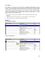
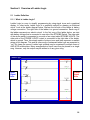
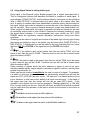
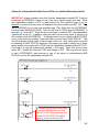
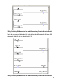
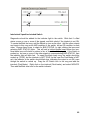
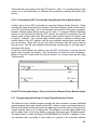
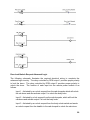
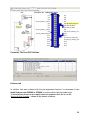
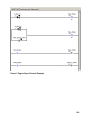
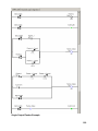
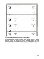
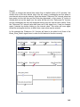
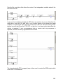
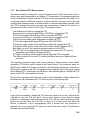
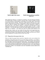
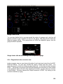
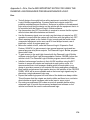
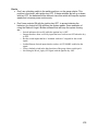
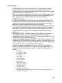
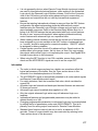
The load manager operates by incrementing or decrementing a “manager” variable. The
process of shedding loads is done by decrementing a variable by a count of one each
time the specified time interval has elapsed. Enabling the outputs is achieved by
incrementing the same variable. When the count reaches zero, all outputs will be OFF.
When the count reaches three, the incrementing will stop and all outputs will be ON.
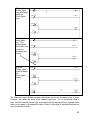
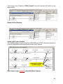
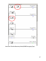
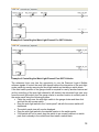
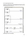
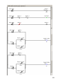
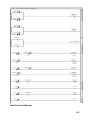
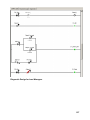
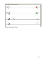
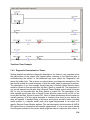
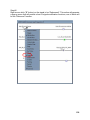
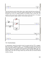
The first rung shows that either the action of turning the ignition key to the Accessory or
Run position OR turning OFF the load manager switch in the instrument panel will set
the load manager to the maximum load number or in other words, turn ON all the
outputs being controlled by the load manager. This action is necessary to force the
outputs ON every time the ignition key is cycled through the OFF position so all outputs
will be operational when the vehicle is initially started. Likewise, if it is desired to stop
the load manager function with the LOAD SHED rocker switch, the act of turning that
switch OFF will also force all the outputs ON immediately. It must be noted that the
load manger count variable should always be set to one count greater than the number
of outputs that are to be controlled. The load manager does not apply the time interval
to the first count reduction once the logical conditions are met to begin shedding.
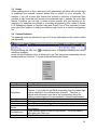
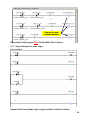
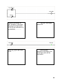
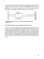
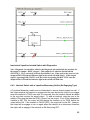
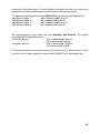
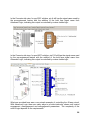
The second rung shows the conditions for setting up the load shedding function. The
logical requirements on the left side of the ladder rung indicate that the LOAD SHED
switch in the instrument panel must be ON and the battery voltage must be less than
11.5 volts. The load-shed variable on the right side of the rung is created in the following
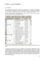
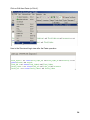
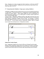
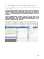
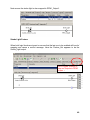
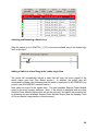
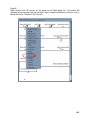
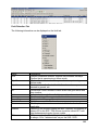
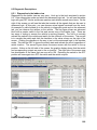
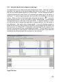
manner. Select the My Variables TAB and move your cursor to the end of the list to the
blank space. Enter the desired name of your load shedder variable in the Custom
Variable Column. Using the left switch of the mouse to drag and drop the new load
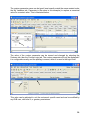
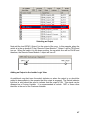
shedder signal to the output side of a blank rung. Now place the cursor over the
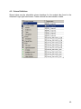
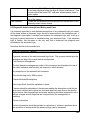
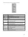
variable and perform a right switch mouse click to reveal a number of options. Select
the Shed option to make this rung a load shedder. Next you will see that the variable is
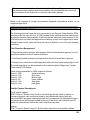
now a load shedder with a default time between sheds of 1 second. You can change
this time by double clicking on the 1-second number until it is highlighted. Now enter
your desired time interval in seconds, being careful to include the s for a unit of
measure. The range for the time interval is from .1 second to 600 seconds. The time
interval between shedding outputs is chosen to be 60 seconds for this example. Repeat
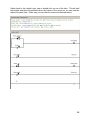
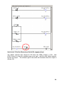
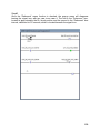
the process on another rung, except select the “LOAD” option to make the variable
enable outputs based upon new logic conditions that may be entered on the left side of
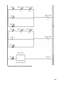
the rung. See the third rung for an example of setting up the loading function. Note that
the time between the loads turning ON is 30 seconds and that the battery voltage must
be greater than 12.3 volts.
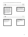
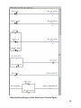
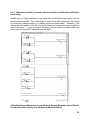
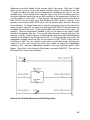
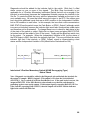
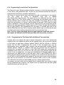
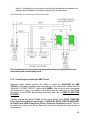
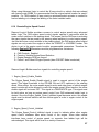
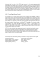
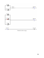
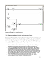
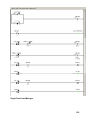
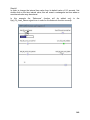
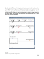
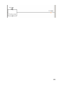
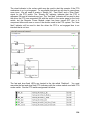
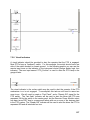
The fourth rung shows the usage of the load managing variable with switches and
Remote Power Module outputs. See that the variable called Manager has been placed
between the input switch and the Remote Power Module output. Used on the input side,
the Manager variable has a sequence number attached to it. This number is
incremented in order to turn outputs ON and decremented in order to turn outputs OFF.
As we stated before, in order for the first output to be turned OFF with the correct
timing, the sequence number below the variable must be one less than the number
entered above in the setup rungs for the load manager. Therefore, our first output to be
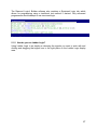
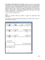
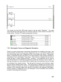
shed has a number 2 attached to it. The second output on rung 6 has a 1 attached to
the same load manager variable. Therefore the sequence of events for load shedding
will be:
121