1
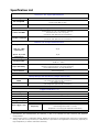
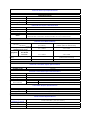
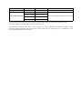
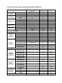
Product Information - Picotest U6200A Universal Counter
The Picotest U6200A offers a higher frequency capability, better oscillator temperature
stability, higher voltage measurement bandwidth, higher resolution and many other benefits
compared with the competition. The U6200A CH3 is included free and has a range from 375
MHz to 6GHz. An optional 20GHz module is also available. The rear inputs are not connected to
the front panel inputs, allowing up to 5 measurement channels. Other benefits compared with
the competition include faster measurements, faster statistics, USB and LAN inputs, better
damage protection levels and electronic calibration. Like all Picotest products, it’s backed by
our 3 yr warranty and 30 day refund policy
•
•
•
•
•
•
•
•
•
•
•
•
•
12 Digit Resolution
Easy to use keypad
1mHz – 400MHz Ch1 and CH2
375MHz to 6GHz on CH 3 included FREE
10MHz synchronization included FREE
Optional rear Inputs are isolated from the front panel allowing 4+1 measurement channels
40ps time domain function resolution.
Time Base Stability: < 1 PPM temperature and <2PPM per year
Optional Oven Stability <5PPB temperature and <80PPB per year
Electronic Calibration
Statistics & Math Functions
20GHz module option available
SCPI commands are compatible with the Agilent 53132A
Detailed Specifications - Picotest U6200A Universal Counter
12 Digits Resolution & 6 GHz Frequency Measurement
The Picotest U6200A universal counter, whose production procedures conform to ISO 9004, has
a frequency resolution of 12 digits per second, 40 ps time interval resolution and a complete set
of test and analysis features. The standard U6200A’s CH3 has a range from 375 MHz to
6GHz and the standard CH 1 & 2 has a range from 1 mHz to 400 MHz.
Great Features for Universal Purposes
The Picotest U6200A also provides great features including Frequency & Ratio (11Digits/Sec.),
Time interval, Period (2.5 ns to 1000s), Duty Cycle, Pulse Width, Rise/Fall Time, Peak Volts (100
Hz~300 MHz), Phase, Totalize, Temperature Stability (< 1 PPM), Aging Rate (< 2 PPM per year),
timebase reference channel and complete Front-End Isolation. Moreover, it offers 20 memory
locations for storing frequently-used operations.
Full Math Functions & Easy Operation Panel
The Picotest U6200A offers built-in statistics and math functions. Users can make
measurements, simultaneously measure and report mean, min/max, delta and standard
deviation. Scale & offset can be easily used for compensation purpose according to the users’
applications. In addition, in order to obtain these measurements, the user can easily use the
numeric buttons to define settings. The U6200 also provides users with visual indications of
selected functions.
Fast Measurement & Special Application
The U6200A supports real-time digital signal processing technology, which can be applied to
analyze data while simultaneously obtaining new readings and speeding measurement. The
“Limit Modes” feature is worth to be mentioning since users can set margin according to their
specific measurements, and via Go-On or Stop and USB Output settings, the U6200A can
continue or stop measuring as a limit is exceeded, and generate an output signal to trigger
external devices.
Free Software & Familiar SCPI Commands
Users can obtain data logs via PC software (Microsoft Excel®) using a USB, or an optional GPIB
interface. Furthermore, U6200A also supports a webserver function, so users can easily control
it via a LAN interface (Figure 10) by entering an Ethernet address (Default: 192.168.0.247) on
web browsers. In addition, through the SCPI commands compatible with Agilent 53132A, the
Picotest U6200A can utilize familiar syntax string for users’ applications. For more command
information, please refer to the U6200A User’s Manual in Chapter 7.
Accessories
1.
2.
3.
4.
High stability oven oscillator module : U6200-OPT01
250MHz-20GHz RF module : U6200-OPT02
Rear Input (CH1/2) module : U6200-OPT04
Rear panel input module -- CH1/2/3 : U6200-OPT05
Specification List
Channel 1 & 2 Input Specifications
DC Coupled
1mHz to 400 MHz
200KHz to 400 MHz (50 Ω)
AC Coupled
30 Hz to 400 MHz (1 MΩ)
FM Tolerance
FM Tolerance: 25%
Voltage Range and Sensitivity
20 mVrms to ±5 V ac + dc (Medium and High)
1mH to 225 MHz
25 mVrms to ±5 V ac + dc (Low)
(75 mVrms with optional rear connectors)
30 mVrms to ±5 V ac + dc
225 MHz to 400 MHz
(75 mVrms with optional rear connectors)
Channel 1 & 2 Input Characteristics
Impedance
1 MΩ or 50 Ω
(ATT X 1, 1 MΩ
24 pF
Capacitance)
(ATT X 10, 1 MΩ
15 pF
Capacitance)
Coupling
AC or DC
100 KHz (or disabled)
Low-Pass Filter
– 20 dB at > 1 MHz
Selectable between Low, Medium(default), or High
Input Sensitivity
Medium is approximately 1.35x High Sensitivity,
low is approximately 1.7x High Sensitivity
Internal Noise
200uVrms(typical)
Voltage Range and Sensitivity (Single-Shot Pulse)
1.5ns to 10ns Pulse
80 mVpp to 10 Vpp
Width
(150 mVpp with optional rear connectors)
50 mVpp to 10 Vpp
>10 ns Pulse Width
(150 mVpp with optional rear connectors)
Trigger Level(ATT x 1)
Range
±5.125 V
Accuracy
±(15 mV + 1% of trigger level)
Resolution
2.5mV
ATT x 10 Range
X 10
Trigger Slope
Positive or Negative
Range
Auto Trigger Level
0 to 100% in 1% steps
Peak Voltage fast mode >10 KHz
Frequency
Peak Voltage slow mode > 100 Hz
Amplitude> 100 mVpp (No amplitude modulation)
1. Specifications and Characteristics for Channels 1 and 2 are identical for both Common and Separate
Configurations.
2. Values shown are for x 1 attenuator setting. Multiply all values by 10 (nominal) when using the x 10 attenuator
setting. Note that it may necessary to recalibrate the input offset in the application environment (especially at
high temperature) to achieve maximum sensitivity.
Damage Level
DC~400MHz 50 Ω
12 Vrms
0 to 3.5 kHz, 1 MΩ
350 V dc + ac pk
3.5 kHz to 100KHz,
350 V dc + ac pk linearly derated to 12 Vrms
1 MΩ
100KHz to 400MHz,
12 Vrms
1 MΩ
Attenuator
Voltage Range
x10
Trigger Range
x10
Channel 3 Input Specifications
Frequency Range
375 MHz to 6 GHz
Channel 3 Input Characteristics
Impedance
50 Ω
Coupling
AC
VSWR
< 2.5:1
Power Range and Sensitivity (Sinusoid)
375 MHz to 500 MHz
-16 dBm to +15 dBm
500 MHz to 1 GHz
-20 dBm to +15 dBm
1 GHz to 2 GHz
-23 dBm to +15 dBm
2 GHz to 4 GHz
-25 dBm to +15 dBm
4 GHz to 5 GHz
-21dBm to +15 dBm
5 GHz to 5.5 GHz
-20 dBm to +15 dBm
5.5 GHz to 6 GHz
-17 dBm to +15 dBm
Damage Level
+25 dBm, DC ±12V
Option Channel 3 Input Specifications (U6200-opt02)
Frequency Range
250 MHz to 20 GHz
Option Channel 3 Input Characteristics (U6200-opt02)
Impedance
50 Ω
Coupling
AC
VSWR
< 2.5:1
Power Range and Sensitivity (Sinusoid, at 25ºC)
250-500MHz
-22~+23dBm
0.5-14GHz
-27~+23dBm
14-15GHz
-21~+23dBm
15-16GHz
-19~+23dBm
16-19GHz
-17~+23dBm
19-20GHz
-13~+23dBm
Damage Level
+26 dBm, DC ±24V
External Arm Input Specifications
Signal Input Range
LVTTL and TTL compatible
Timing Restrictions
Pulse Width
> 50 ns
Transition Time
< 250 ns
Start-to-Stop Time
> 50 ns
Damage Level
12 Vrms
External Arm Input Characteristics
Impedance
1 kΩ
Input Capacitance
17 pF
Start Slope
Positive or Negative
Stop Slope
Positive or Negative
1. External Arm is available for all measurements except Peak Volts.
Notes
2. External Arm is referred to as External Gate for some measurements.
Internal Time Base Stability
Temperature Stability
(referenced to 25°C)
Standard
High Stability Oven
(0° to 50°C)
(U6200-opt01 for U6200A only)
± 1 x 10E-6
± 5 x 10E-9
Per Day
Aging Rate
± 8 x 10E-10
Per Month
Per Year
± 2 x 10E-6
± 8 x 10E-8
Turn-on stability vs. time (30
± 2.0 x 10E-8
min.)
(referenced to 24 hours)
Calibration
Electronic
Electronic
External Time Base Input Specifications
Voltage Range
200 mVrms to 10 Vrms
Damage Level
12 Vrms
External Time Base Input Characteristics
Threshold
0V
Impedance
1 kΩ
Input Capacitance
25 pF
Input Frequency
10 MHz
Internal vs. External Time
Manual
Select Internal or External
Base Selection
Automatic
Internal used when External not present (default)
Time Base Output Specifications
Output Frequency
10 MHz
Voltage
570 mVpp (0 dBm), typical
Impedance
50 Ω (typical), AC coupled
Measurement Specifications
Frequency, Period
Channel 1 and 2
Trigger
“Auto” Gate Time
STD CH 3
1 mHz to 400 MHz
(2.5 ns to 1000 s)
Default setting is Auto Trigger at 50 %
0.1 sec
375 MHz to 6 GHz
(0.166 ns to 2.6 ns)
Frequency Ratio
CH 1/ CH 2, CH 1/ CH 3, CH 2/ CH 1, CH 3/ CH1
(Measurement is specified over the full signal range of each input.)
Results Range
10E-10 to 10E+11
“Auto” Gate Time
0.1 sec
Time Interval
Measurement is specified over the full signal ranges of Channels 1 and 2. The width of the
Trigger
Default setting is Auto Trigger at 50 %
Results Range
-0.5 ns to 10E+5 s
pulse must be greater than 1 ns, frequency range to 300 MHz.
Resolution
40 ps
RMS Resolution
120 ps
Systematic
Uncertainty
Pulse Width Time
±(TI × Time Base Error) ± Trigger Level Timing Error ± 500 ps Differential Channel Error
Measurement is specified over the full signal range of Channel 1. The width of the pulse
must be greater than 1 ns frequency range to 300 MHz).
Pulse Selection
Positive or Negative
Trigger
Default setting is Auto Trigger at 50%
Results Range
1.5 ns to 10E+5 s
Resolution
40 ps
RMS Resolution
120 ps
Systematic
± (Pulse Width Time x Time Base Error) ± Trigger Level Timing Error ± 500 ps Differential
Uncertainty
Channel Error.
Rise/Fall Time
Measurement is specified over the full signal range of Channel 1. The width of the pulse
must be greater than 1 ns frequency range to 300 MHz).
Edge Selection
Positive or Negative
Trigger
Default setting is Auto Trigger at 10% and 90%
Results Range
2 ns to 10E+5 s
Resolution
40 ps
RMS Resolution
120 ps
Systematic
± (Edge Time x Time Base Error) ± Trigger Level Timing Error ± 500 ps Differential
Uncertainty
Channel Error
Phase
Measurement is specified over the full signal range of each input. The width of the pulse
Results Range
-180° to +360°
must be greater than 1 ns, frequency range to 300 MHz
Resolution
40 ps
RMS Resolution
120 ps
Systematic
± (Trigger Level Timing Error) ×Frequency
Uncertainty
Duty Cycle
Measurement is specified over the full signal range of Channel 1. The width of the pulse
must be greater than 1 ns, frequency range to 300 MHz
Pulse Selection
Positive or Negative
Trigger
Default setting is Auto Trigger at 50 %
Results Range
0 to 1
Resolution
40 ps
RMS Resolution
120 ps
Systematic
Uncertainty
Totalize
± Trigger Level Timing Error ± 500 ps Differential Channel Error
Measurement is specified over the full signal range of Channel 1. The width of the pulse
must be greater than 1 ns, frequency range to 400 MHz
Pulse Selection
Positive or Negative
Trigger
Default setting is Trigger at 0 V
Results Range
0 to 10E+15
Resolution
1 count
Systematic
± 1 count
Uncertainty
Peak Voltage
Results Range
-5.1 V to + 5.1 V
Resolution
2.5 mV
DC Signals
15 mV + 2 % of V
peak-to-peak amplitude greater than 200 mV
DC Signals (ATT x 10)
150 mV + 2 % of V
peak-to-peak amplitude greater than 1 V
100 Hz ~ 10 KHz 15 mV + 2 % of V
1 Vp-p, 50 Ω, ATT OFF
10 KHz ~ 5 MHz
15 mV + 4 % of V
5 MHz ~ 80 MHz
15 mV + 7 % of V
peak-to-peak amplitude greater than 200 mV
80 MHz ~ 300 MHz 15 mV + 15 % of V
The peak volts measurement will keep operating up to 400 MHz, although results act as references only.
Tres is the resolution including effect of certain internal errors.
The differential channel Error terms which counted by many systematic uncertainty equations result
channel-to-channel disaccord and internal noise. These issues can be improved by the TI calibration in the
well-controlled temperature environment.
Preset Values and Save/Recall Information
Input
Impedance
CH1
Input
Attenuation
CH1
CH2
CH2
CH1 (percent)
Trigger Level
CH2 (percent)
CH1 (volts)
CH2 (volts)
CH1
Trigger Slope
CH2
CH1
Sensitivity
CH2
Scale
Offset
Limit test on/off
Limits
parameters
On fail stop/go on
Lower limit
Upper limit
Stats on/off
Measurement count
Display
Stat
measurement/stats
parameters
Use all/in limits
On-single
measurement
Timebase
Channel 1 trigger
offset Inp1 cal
Channel 2 trigger
Trigger
offset Inp2 cal
Offset Cal
Channel 1 trigger
Parameters
offset Att1 cal
Channel 2 trigger
offset Att2 cal
Channel 1 trigger
gain Inp1 cal
Channel 2 trigger
Trigger Gain
gain Inp2 cal
Cal
Channel 1 trigger
Parameters
gain Att1 cal
Channel 2 trigger
gain Att2 cal
Time Interval
Offset Cal
Parameters
Fine1
Fine2
Quick
Timebase cal Parameters
Value at *RST
( GPIB Reset )
In
Save/Recall
In non-volatile
memory
1E+6Ohms
1E+6Ohms
x1
x1
50
50
0
0
positive
positive
medium
medium
1
0
off
go on
0
0
off
100
yes
yes
yes
yes
yes
yes
yes
yes
yes
yes
yes
yes
yes
yes
yes
yes
yes
yes
yes
yes
no
no
no
no
no
no
no
no
no
no
no
no
no
no
no
no
no
no
no
no
measurement
yes
no
all
yes
no
1
yes
no
auto
yes
no
no
yes
no
yes
no
yes
no
yes
no
yes
no
yes
no
yes
no
yes
no
no
no
no
yes
yes
yes
yes
General Specifications
Item
Power Supply Voltage
Power Requirements
Limitation & description
100V/240V ± 10% 50Hz~60Hz ± 10%
100V/120V ± 10% 400Hz ± 10%
50 VA Maximum
Maximum relative humidity 80% for
Operating Humidity
temperature up to 31°C decreasing linearly
to 50% relative humidity at 40°C
Operating Environment
Storage Temperature
Operating Altitude
Bench Dimensions
(WxHxD)
Weight
Safety
EMC
0 to 55°C
- 40°C to 70°C
Up to 2000m
210mm x 85mm x 350mm
3200g
IEC61010-1:2001/EN61010-1:2001 (2nd
Edition)
EN61326, IEC61000-3, IEC61000-4
Warm-up Time
1 Hour
Warranty
1 Year
1. U6200-opt01: High Stability Oven
2. U6200-opt02: 250 MHz~20 GHz Input Channel 3.
Accessory
3. U6200-opt04: Rear panel input module (CH1/CH2)
4. U6200-opt05: Rear panel input module (CH1/CH2/CH3)
5. M3500-opt04: GPIB Card
Specifications are subject to change without notice.
All other trademarks and trade names are the property of their respective companies.