1
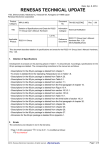
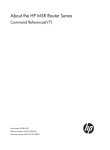
Power Management Features of X86 Microprocessors ® Authors: Jack R. Smith and Sebastian Ventrone Application Note Introduction This paper describes techniques to control power consumption in X86-based computers. The IBM 486 series, Intel® 486 series and Intel Pentium series microprocessors are studied, and their power management features are compared. Each processor studied has the ability to manage power in one or more ways. The proces- sors are similar in this respect, but there are vast differences in the ways they perform this task. IBM announced a new feature on 486DX2/DX4 to reduce these differences. Background on Power Management X86 power management allows the microprocessor to regulate the amount of electrical power consumed by the system. Using power management, the microprocessor can control its own power as well as the power consumed by system logic, memory and peripheral devices. Power management is important to customers for the following reasons: 1) it reduces the cost of operating office systems, 2) it extends battery life in portable systems and 3) it conforms to applicable international energy standards. The original Thinkpad portable computer contained an Intel 386SX microprocessor. 1986, In IBM developed a Thinkpad based on the IBM 386SLC processor that has an on-chip cache and a faster clock. power consumption. However, a major drawback of the original 386SLC design was its The original 386SLC consumed more power than the Intel 386SX. Several engineering discussions were held to solve this problem, and it was determined that power could be significantly reduced by implementing an efficient shutdown procedure. The new shutdown procedure became known as the IBM power management architecture, and is implemented in current versions of the IBM 386SLC, 486SLC2 and Blue Lightning processors. The core of the new architecture is a new mode of operation (System Management Mode) which is accessed through a chip input (PWI# or SMI#). When the input is asserted, the processor finishes the current instruction, saves the state of the CPU to memory and enters System Management Mode. If the processor is using an on-chip write-back cache, it must be flushed before removing power from the processor. When power is returned, the processor restores the state of the CPU and resumes processing in the mode it was in prior to receiving the PWI interrupt. In addition to System Management Mode, IBM added to the 386SLC a low power halt Page 1 of 12 October 12, 1995 Fax #40012 function and a dynamic frequency shift protocol. Low power halt allows the processor to turn off its internal clocks during the halt state to achieve minimum standby power. Dynamic frequency shift allows the system to reduce the external clock frequency at certain times, which reduces power consumption. An X86 microprocessor can manage power in the following ways: 1. System Management Mode 2. Low Power Halt 3. Adjustable Core Clock Multiplier 4. Dynamic Frequency Shift 5. Additional Features The first feature controls system power, and the other features control the processor only. Table 1 (on the following page) shows the power management pins on each processor. System Management Mode System Management Mode (SMM) is an X86 operating environment which allows the processor to manage power through software which runs transparent to the operating system and applications programs. SMM mode is intended for use only by system firmware, not by applications. Many things can be done in SMM mode. state or shutdown, as described earlier. An idle processor can be put into a low power This is an ideal application for portable PCs, where clos- ing the lid can trigger an SMM interrupt to prepare for shutdown. The concept can be extended to desktop systems, where the processor can be powered down if it has been idle for some time. SMM mode can also manage I/O devices. and powered up when they are needed. Devices can be powered down when not in use, When instructions are directed to an offline device, SMM software suspends activity to this device, powers up the device and reissues the instruction stream. SMM mode is entered through a dedicated hardware interrupt and uses a separate memory space (SMRAM) which holds the CPU state and interrupt service routine. When an SMM in- terrupt occurs, the processor finishes the current instruction and then saves the CPU state to the header area in SMRAM. It resets some architected registers, disables INTR and NMI interrupts, enters Real addressing mode and begins executing the service routine. The locations of the header and service routine are specified by each processor. The service routine is developed by the system designer and installed in SMRAM at boot up. The last instruction in the routine causes the processor to exit the routine, refresh the CPU state from SMRAM and resume executing in the mode it was in prior to receiving the SMM Page 2 of 12 October 12, 1995 Fax #40012 PWI# System SMI# PWI_RDY# BLSX2/SX3 Core Clock Multiplier Dynamic Frequency I486DX2 SUSPA# Halt 486DX2 SUSP# Low Power SMI# SMIACT# SMADS# PWI_ADS# SL Enhanced SMI# Management Mode Standard Intel Pentium I486DX4 DFS_REQ# SMIACT# CLKMUL P5 P54C (60 or 66 (90 or 100 MHz) MHz) SMI# SMI# SMIACT# SMIACT# BF Pentium P5 4C DX2/DX4 Pentium P5 I486DX2 IDX4 486 SL Enhanced I486DX2 BLSX2/SX3 DFS_RDY# Shift UP # Additional UP# Features STPCLK# STPCLK# UP# UP# STPCLK# 1 Table 1: I/O Pins for Power Management 1 Numbers in the heading of this and the following tables designate entries in the References Sec- tion at the end of this document. interrupt. For the IBM 486SX2 and 486SX3 processors, the PWIRET instruction performs this function. All other processors studied use the RSM instruction to exit SMM mode. Figure 1 illustrates the transi- tion to and from SMM mode. Below is a technique to put the CPU into a low power state: 1. Flush the cache (if using Intel CPU or early revisions of IBM 486DX2/DX4. Intel CPUs may cache accesses to SMM memory, so the cache must be flushed upon SMM entry and exit. Rev. 4.1 and earlier of IBM 486DX2/DX4 does not snoop the bus during halt.) 2. Enter SMM mode 3. SMM routine enables INTR or NMI, then executes HLT to enter low power state 4. Stop external clock to processor When the processor is needed, start the external clock, interrupt the halt state, and exit SMM. Below is a technique to shutdown the CPU: 1. Flush the cache (if write-back) 2. Enter SMM mode 3. SMM routine copies header (CPU state) to another memory location and sets an SMM indicator bit in memory. 4. Disconnect power to CPU Page 3 of 12 Date Issued 10/12/95 Fax #40012 After power is returned, the CPU resets. BIOS reads the SMM indicator bit from mem- ory, determines that the CPU was in SMM mode before shutdown and gives an SMM interrupt. The CPU enters SMM mode. The SMM routine reads the original CPU state from the other memory location, puts it into the header in SMRAM and exits SMM mode. SMM provides a faster but more risky means of shutting down the CPU than the traditional method. trolled by processor microcode and runs independent of the operating system. Application Program Save state Reset registers Disable interrupts Enter Real mode instruction instruction instruction instruction SMM is con- The traditional Header instruction instruction SMM interrupt SMM Service Routine instruction Restore State return (PWIRET or RSM) Figure 1: SMM Execution Flow method uses standard interrupt protocol (assert INTR pin, execute power management routine, return via IRET instruction) and relies on the operating system to ensure proper operation. traditional method is used today. The The SMM method will be used in future systems. All of the processors listed in Table 1 above, except the standard version of the Intel 486DX2/DX4, implement SMM mode. All come with SMM enabled at power up, except IBM 486DX2/DX4 which must configure SMM before it can be used. offer a hardware interrupt. All processors listed in Table 1 The IBM processors also offer a software interrupt. The hardware interrupt on IBM 486SX2 and 486SX3 is PWI#, and all other processors listed in Table 1 use SMI#. processors. The pin is bidirectional on IBM processors and unidirectional on Intel On IBM processors, the system drives the pin to enter SMM mode and then the CPU drives the pin when it is in SMM mode. Intel processors do this differently. For Intel processors SMI# as an input only, and SMIACT# is an output asserted when SMM mode is active. Since In- tel processors have separate interrupt and acknowledge pins, they can process nested SMM interrupts. Another pinout difference between IBM and Intel processors is memory address strobes. IBM processors have two address strobes (ADS# for normal accesses, PWI_ADS# or SMADS# for SMM accesses). Intel processors have one address strobe (ADS#), and the SMIACT# signal differentiates normal accesses from SMM accesses. Page 4 of 12 October 12, 1995 Fax #40012 All processors listed in Table 1, except Intel Pentium P5, support I/O instruction restart during SMM. This function is enabled through a configuration register (IBM SX2 and SX3) or bits in the SMM header (IBM 486DX2/DX4, Intel DX4, Intel Pentium P54C). Table 2 (on the following page) lists the SMM features on each processor. For some time, the pinout differences made SMM incompatible from processor to processor. Recently, IBM announced a new feature to clear this up. On the 3.3 volt version of the Blue Lightning 486DX2/DX4, the SMM hardware interface can be made functionally compatible with Intel SL Enhanced 486DX2/DX4 by setting a configuration bit. If bit 3 in configuration register CCR3 is set, IBM's SMI# pin is compatible with Intel's SMI# pin and the SMADS# pin is compatible with Intel's SMIACT# pin. If this bit is reset, the chip operates as it did before. The soft- ware interrupt is not available when CCR3(3) is set. Page 5 of 12 October 12, 1995 Fax #40012 BLSX2/SX3 I486DX2 IBM 486DX2/DX4 Std. I486DX4 SL Enhanced Intel Pentium P5(60 or 66MHz) P54C (90 or 100MHz) Entry HW: Assert PWI# 12cycles SW: PWIBP instruction Exit PWIRET instruction HW: Assert SMI# Assert SMI# Assert SMI# 1 Assert SMI# 1 Assert SMI# 1 1 cycle cycle cycle cycle RSM instruction RSM RSM instruction RSM instruction or RESET instruction RESETor INIT RESET or INIT Always enabled Always enabled 2 cycles SW: SMINT instruction RSM instruction or RESET Enable Always Enabled or RESET HW: Always enabled CCR1(1)=1 Always enabled CCR1(2)=0 SMAR(3:0)>0 SW: CCR1(1)=1 CCR1(2)=1 SMAR(3:0)>0 Header Location Service Routine Location 00060000h- Defined by 0003FE00h - 0003FE00h - 0003FE00h - 0003FE00h - 0006014Ch SMAR 0003FFFFh 0003FFFFh 0003FFFFh 0003FFFFh (relocatable) (relocatable) (relocatable) (relocatable) Bootstrap Defined by 00038000h 00038000h 00038000h 00038000h address at SMAR (relocatable) (relocatable) (relocatable) (relocatable) FFFFFFF0h During System Management Mode (SMM) INTR NMI Disabled Disabled Disabled. Disabled. Disabled. Disabled. Disabled. Enabled by Enabled by Enabled by Enabled by Enabled by STI instruction STI STI STI STI instruction instruction instruction instruction Disabled, 1 Disabled, 1 Disabled, 1 Disabled, 1 Disabled, 1 event latched. event latched. event latched. event latched. event latched. Enabled by Enabled by IRET Enabled by Enabled by IRET Enabled by IRET CCR3(1). instruction. IRET instruction. instruction. 1 event latched. 1 event latched. instruction. SMM NO, PWI# is NO, SMI# is Interrupt output during output during SMM mode. SMM mode. YES, if IF=1 YES HALT or MSR1000 1 event latched. 1 event latched. YES, if INTR or YES, if INTR YES, if INTR or YES, if INTR or NMI enabled. or NMI NMI enabled. NMI enabled. [5]=1 enabled. Warm None Reset A20M# Recognized NO NO NO INIT INIT Ignored Recognized Recognized Recognized Recognized Access Cached to System Memory Access to SMM Memory Cached Cached Cached Cached Cached Not cached Cached, unless Cached, unless Cached, unless Cached, unless KEN# =1 during KEN# =1 KEN# =1 during KEN# =1 during access during access access access Not cached Table 2: System Management Mode Page 6 of 12 October 12, 1995 Fax #40012 Low Power Halt All of the processors listed in Table 3, except the standard version of Intel 486DX2/DX4 and the Intel Pentium P5, offer a low power halt function. struction. This is accessed through the HLT in- The IBM 486DX2/DX4 also offers hardware entry through the SUSP# pin. The IBM processors must enable this function before it can be used, and Intel processors always have this function enabled. The IBM processors stop the internal clocks during low power halt. The exter- nal clock on the Intel Pentium P54C cannot be stopped the during this state, it must return to normal state before stopping the external clock. Table 3 summarizes the low power halt feature. BLSX2/SX3 I486DX2 IBM 486DX2/DX4 Std. Entry HLT instruction SL Enhanced HW: SUSP# HLT SW: HLT instruction I486DX4 Intel Pentium P5(60 or P54C (90 or 66 MHz) 100MHz) HLT instruction HLT instruction instruction Exit Enable RESET, PWI#, HW: RESET, RESET, RESET, INIT, INTR or NMI deassert SUSP# SRESET, SRESET, SMI#,INTR or SW: RESET, SMI#, SMI#,INTR or SMI#,INTR or INTR or NMI NMI Always enabled ON Always enabled ON MSR1000[13]=1 Table 3: OFF NMI HW: CCR2[7]=1 SW: Internal Clocks RESET or CCR2[3]=1 OFF NMI Always enabled ON Low Power Halt Adjustable Core Clock Multiplier This feature allows the speed of the CPU core clock to be adjusted with respect to the external bus clock. It is available on the IBM 486SX2, IBM 486SX3, Intel DX4 and 100MHz ver- sion of the Intel Pentium P54C. The other processors in Table 4 operate the core at a fixed ratio (2x for 486DX2 & 3x for 486DX4 CPUs, 1x for Intel Pentium P5, 1.5x for 90MHz Intel Pentium P54C). The IBM 486SX2 and 486SX3 are capable of running the core at 1x, or 2x. The 486SX3 can also run the core at 3x. ter after RESET. The default is 1x, and it is controlled by writing a configuration regis- The Intel DX4 operates the core at 2x or 3x. trolled by tying the CLKMUL pin at RESET. The default is 3x, and it is con- The 100MHz version of the Intel Pentium P54C operates the core at 1.5x or 2x, with a maximum internal frequency of 100MHz. It is controlled by tieing the BF pin at RESET. Table 4 shows the core clock multiplier for each processor. Page 7 of 12 October 12, 1995 Fax #40012 BLSX2/SX3 Multiple IBM I486DX2 486DX2 486DX4 Standard 2X 1X, 2X or 3x. 3X SL Enhanced 2X 2X Intel Pentium I486DX4 2X, 2.5X or 3X. P5(60 or P54C (90 or 66MHz) 100MHz) 1X 1.5X or 2X. Default is 1X. Write Default is 3X. Tie Default is 1.5X. MSR1002[26:24] CLKMUL at Tie BF at RESET after RESET. RESET 2X: CLKMUL=V SS 2.5X: CLKMUL=BREQ 3X: CLKMUL=V or cc floating Table 4: Core Clock Multiplier Dynamic Frequency Shift This feature is available on all IBM processors, Intel SL Enhanced 486DX2, Intel DX4 and Intel Pentium P54C. power up. It allows the system to vary the frequency of the external clock after The IBM 486SX2 and 486SX3 activate this feature through the DFS_REQ# pin or a configuration bit. The IBM 486DX2/DX4 always has this feature ready for use, and Intel proces- sors activate this through the STPCLK# pin. Table 5 shows how to use dynamic frequency shift on each processor. BLSX2/SX3 BL486DX2 /DX4 I486DX2 Std SL Enhanced I486DX4 Intel Pentium P5(60 or P54C (90 or 100 66MHz) MHz) HW: Assert DFS_REQ#, Change Assert STPCLK# Assert STPCLK# Assert STPCLK# wait for DFS_RDY#, then frequency then change then change then change change frequency of CLK2. of clock any frequency of frequency of CLK. frequency of SW: Set MSR1002[27] wait time. CLK. Always Always enabled CLK. for MSR1002[28], then change frequency of CLK2. Enable HW:MSR1000[10]=1 MSR1000[29]=1 Always enabled Always enabled enabled SW: Always enabled Table 5: Dynamic Frequency Shift Additional Features Table 6 shows some additional power management features. ity to stop the external clock. The primary one is the abil- Stop clock is available on all processors except the standard ver- sion of Intel 486DX2/DX4 and Intel's Pentium P5. It is accessed through the HLT instruction on IBM processors and the STPCLK# pin on Intel processors. The IBM 486DX2/DX4 can also stop clocks using the SUSP# pin. Page 8 of 12 October 12, 1995 Fax #40012 BLSX2/SX3 I486DX2 Standard IBM 486DX2/DX4 No Stop External Yes Yes Clock (HLT) (HLT or SL Enhanced I486DX4 Yes Yes (STPCLK#) (STPCLK#) Intel Pentium P5(60 or P54C (90 or 66MHz) 100MHz) No Yes (STPCLK#) SUSP#) Tri-state Outputs No & Power Down Cache Low Power Yes Yes Yes Yes Yes (UP#) (UP#) (UP#) (UP#) No No No No No No No No No No No No No Yes. Yes. No No CPU CPU reduces core reduces clock to 1X core clock when idle to 1X when and waiting idle and for read data waiting for from read data memory or from I/O. memory or 5.0V 3.3V (MSR1004[28]) FPU powers down No Yes when idle CPU powers down No No No when idle I/O. Power Supply 3.0V - 4.2V 3.3V or 5.0V 5.0V 3.3V or 3.45V 5.0V Table 6: Additional Features Power Saving Comparison Tables 7 and 8 give numeric values for power dissipation in the normal and low power states. Most notable in the low power state is the Intel Pentium P54C, which consumes much more power than any other processor in Table 8 when the external clock is running. Page 9 of 12 October 12, 1995 Fax #40012 BLSX2/SX3 I486DX2 Standard IBM 486DX2/DX4 SL Enhanced I486DX4 Intel Pentium P5(60 or 66MHz) P54C (90 or 100MHz) V cc=3.3V Icc=0.46A (1) Icc=1.86A P=1.52W P=6.15W (f=50MHz) (f=90MHz) Icc=1.18A (1) P=3.9W (f=100MHz) Icc=0.83A (1) Vcc=3.45V P=2.85W (f=75MHz) Icc=1.17A (2) P=4.04W (f=100MHz) V cc=3.6V Icc=0.73A P=2.63W (f=75MHz SX3) V cc=4.2V Icc=1.16A P=4.87W (f=100MHz SX3) V cc=5.0V Icc=0.78A (1) Icc=0.98A (1) Icc=2.37-2.60A P=3.88W P=4.88W (1) (f=50MHz) (f=66MHz) P=11.85-13.0W (f=60-66MHz) Icc=1.03A P=5.13W (f=66MHz) Note: "f" indicates internal operation frequency. Table 7: CPU Power Dissipation Under Normal Conditions Values in table 7 are the BAPCo 93 ratings in all cases except: (1) value listed in Intel databook (2) DOS edit prompt with menu pulled down. Page 10 of 12 October 12, 1995 Fax #40012 BLSX2/SX3 I486DX2 Standard IBM 486DX2/DX4 Enter HLT when HLT when No low power Low MSR1000[13]= CCR2[3]=1 or state Power 1 SUSP# when SL Enhanced STPCLK# I486DX4 STPCLK# Intel Pentium P5(60 or P54C (90 or 66MHz) 100MHz) No low STPCLK# power state CCR2[7]=1 State External Clock On V cc=3.3V Icc=9-16 mA Icc=20-23 mA Icc=424-470 mA P=30-53 mW P=66-76 mW P=1400-1550 mW (f=33-80 (f=40-50 MHz) (f=90-100 MHz) MHz) Icc=75-100 mA Vcc=3.45V P=259-345 mW (f=75-100 MHz) V cc=3.6V Icc=30 mA P=108 mW (f=75 MHz) Vcc=5.0V Icc=13-18 mA I P=63-90 mW P=175-225 (f=33-80 mW MHz) (f=50-66 MHz) cc=35-45 mA External Clock Off V cc=3.3V Icc=450 µA Icc=100 P=1.5 mW µA Icc=90 P=0.33 mA V µA P=0.3 mW Icc=1 mA cc=3.45V P=3.45 mW V cc=3.6V Icc=4 mA P=15 mW Vcc=5.0V Icc=450 µA Icc=200 P=2.3 mW µA P=1 mW Note: "f" indicates internal operation frequency. Information obtained from databooks. Table 8: CPU Power Dissipation in Low Power State Conclusion This paper described five power saving features available on X86 processors. It explained how to use each feature and discussed advantages and disadvantages of certain processors. When selecting a processor for a system, the designer should consider the benefits of power management and decide which features are needed. For more information, please consult the references listed below. Page 11 of 12 October 12, 1995 Fax #40012 References: 1. IBM 486 DX2 Addendum to the IBM Blue Lightning 486 DX2 Databook, August 11, 1995 2. Intel 486 Microprocessor Family Databook, 1994 3. Enhanced Am486 Microprocessor Family Datasheet, May, 1995 4. IBM 486 DX4 Addendum to the IBM Blue Lightning 486 DX2 Databook, September 12, 1995 5. IBM Blue Lightning 486 DX2 Databook, 1994 6. IBM Blue Lightning Microprocessor Datasheet, February 7, 1994 7. Pentium Family User's Manual, 1994 IBM Corporation 1995. All rights reserved. IBM and the IBM logo are registered trademarks of International Business Machines Corporation. IBM Microelectronics is a trademark of the IBM Corp. All other product and company names are trademarks/registered trademarks of their respective holders. 1995 IBM Corp. This document may contain preliminary information and is subject to change by IBM without notice. IBM makes no representations or warranties that the use of the information or applications herein shall be free of third party intellectual property claims and assumes no responsibility or liability from any use of the information contained herein. Nothing in this document shall operate as an express or implied license or indemnity under the intellectual property rights of IBM or third parties. The products described in this document are not intended for use in implantation or other direct life support applications where malfunction may result in physical harm or injury to persons. NO WARRANTIES OF ANY KIND, INCLUDING BUT NOT LIMITED TO THE IMPLIED WARRANTIES OF MERCHANTABILITY OR FITNESS FOR A PARTICULAR PURPOSE ARE OFFERED IN THIS DOCUMENT. All performance data contained in this publication was obtained in a specific environment, and is presented as an illustration. The results obtained in other operating environments may vary. Page 12 of 12 October 12, 1995 Fax #40012