1
VACAM ANPR
Ex-Sight.Com™
VACAM ANPR User Manual
Version 2.0
Last Update: 15.8.13
Page 1 of 78
User Manual
VACAM ANPR
Contents
1
Overview............................................................................................................... 5
1.1
2
3
The Advantages of VACAM ANPR ................................................................................................................................. 5
VACAM ANPR Main Panel ............................................................................... 6
VACAM ANPR integration with Ex-Sight’s products ....................................... 7
VACAM Remote Viewer Connectivity with VACAM ANPR ........................................................................................................ 7
3.1
VACAM ANPR Settings tab ............................................................................................................................................ 9
3.2
Directories ................................................................................................................................................................... 10
4
5
6
Installation Guide .............................................................................................. 11
The VACAM ANPR Activation ......................................................................... 12
First time software usage .................................................................................. 13
First Time Usage: .................................................................................................................................................................... 13
Open a new channel: .............................................................................................................................................................. 14
7
Main Panel Functionalities .............................................................................. 16
7.1
Source Area ................................................................................................................................................................. 17
7.1.1
Video Source (VLC) .............................................................................................................................................. 17
7.1.2
Still Images Source............................................................................................................................................... 19
7.1.3
Snapshots Source ................................................................................................................................................ 20
7.2
Real time Notifications Area ....................................................................................................................................... 21
7.3
Current Detection History Area................................................................................................................................... 22
7.3.1
PTZ (Pan Tilt Zoom) Panel.................................................................................................................................... 24
7.3.2
Masking options .................................................................................................................................................. 25
7.4
8
9
Status Bar .................................................................................................................................................................... 28
Access List Tab .................................................................................................. 31
History Tab ........................................................................................................ 32
9.1
History Tab options ..................................................................................................................................................... 33
9.2
Log display & Search example ..................................................................................................................................... 34
10
Settings Tab: Advanced User Settings .............................................................. 35
10.1
General Settings Section ............................................................................................................................................. 36
10.1.1
Access List............................................................................................................................................................ 36
10.1.2
Automatic Video Start ......................................................................................................................................... 36
10.1.3
Channel Information ........................................................................................................................................... 36
10.1.4
Country Code ....................................................................................................................................................... 36
10.1.5
Detection ............................................................................................................................................................. 37
10.1.6
Directories ........................................................................................................................................................... 38
10.1.7
Engine Settings .................................................................................................................................................... 39
Page 2 of 78
User Manual
VACAM ANPR
10.1.8
Graphic User Interface ........................................................................................................................................ 40
10.1.9
Mask .................................................................................................................................................................... 41
10.1.10
PTZ Control ...................................................................................................................................................... 42
10.1.11
Queues Management ...................................................................................................................................... 42
10.1.12
Relays (COM) ................................................................................................................................................... 43
10.1.13
Relays (IP) ........................................................................................................................................................ 44
10.1.14
Security: ........................................................................................................................................................... 44
10.1.15
Storage Settings............................................................................................................................................... 45
10.1.16
TCP Communication ports ............................................................................................................................... 46
10.1.17
Triggers ............................................................................................................................................................ 47
10.1.17.1
BF Trigger......................................................................................................................................................... 48
10.1.17.2
NVC Trigger...................................................................................................................................................... 48
10.1.17.3
Snapshot Settings ............................................................................................................................................ 49
10.1.17.4
Trigger ............................................................................................................................................................. 50
10.1.18
Video Frames Queue ....................................................................................................................................... 51
10.1.19
VLC Settings ..................................................................................................................................................... 52
10.2
Engines Section ........................................................................................................................................................... 54
10.2.1
Alpha-Numeric Characters .................................................................................................................................. 54
10.2.2
Character Height ................................................................................................................................................. 54
10.2.3
Engine queue ....................................................................................................................................................... 54
10.2.4
General engine settings....................................................................................................................................... 55
10.3
11
PTZ Scripts Section ...................................................................................................................................................... 56
Appendix A: VACAM ANPR Detection Process, Queues & Actions .............. 57
11.1
Video Source (VLC) ...................................................................................................................................................... 57
11.2
Still Images Source ...................................................................................................................................................... 59
11.3
Snapshots Source ........................................................................................................................................................ 60
12
Appendix B: PTZ Control ................................................................................. 61
12.1
Main PTZ Panel ............................................................................................................................................................ 61
12.2
Presets+ Panel ............................................................................................................................................................. 62
12.3
Record/Play PTZ Scripts Panel ..................................................................................................................................... 63
13
Appendix C - Optional Hardware Components ............................................... 64
13.1
EasyDAQ USB(COM) 4 channels Relay Controller ....................................................................................................... 64
13.2
Setup & Configure EasyDAQ USB(COM) Relay Controller........................................................................................... 65
Page 3 of 78
User Manual
VACAM ANPR
13.3
BF-1010 Network (IP) 10 channels Relay Controller ................................................................................................... 66
13.4
Setup & Configure BF-1010 Network (IP) 10 channels Relay Controller .................................................................... 67
13.5
NVC Camera/Encoder.................................................................................................................................................. 70
13.6
Setup & Configure NVC Camera/Encoder ................................................................................................................... 71
13.7
HDIR Camera ............................................................................................................................................................... 74
13.8
Setup & Configure HDIR Camera ................................................................................................................................. 76
13.8.1
RTSP Stream names............................................................................................................................................. 77
13.8.2
Video Profiles ...................................................................................................................................................... 77
13.8.3
Digital Input & Digital Output .............................................................................................................................. 78
Page 4 of 78
User Manual
VACAM ANPR
1 Overview
VACAM ANPR is multi channel License Plate Recognition software designed for detection,
identification and tagging of vehicle license plates for different applications, both commercial and
governmental. The system incorporates most advanced multi level recognition algorithms. Each
captured plate is classified according to predefined vehicle lists. This classification allows the
program to alert to each type of detected plates accordingly. For instance, as a vehicle approaches
an entrance gate, it is automatically opened or shut depending on the status of an identified plate.
VACAM ANPR operates with IP or Analog video sources based either on constant video stream or
on such external triggers as electrical signals, dry contacts, or video content analysis.
1.1 The Advantages of VACAM ANPR
Trigger devices support
Relay support
Frame masking
Advanced license plate search
Plate deviation angle +45° to -45°
Plate filtering
PTZ (Pan|Tilt|Zoom) control
Automatic video signal recovery
Circular storage management
Vehicle detection statistics
Embedded system time sync.
Remote restart support | access list
Username &password authentication
Page 5 of 78
User Manual
VACAM ANPR
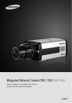
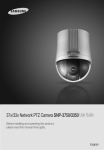
2 VACAM ANPR Main Panel
MINIMUM REQUIREMENTS
CLIENT:
DUAL CORE CPU
2GB RAM
MICROSOFT WINDOWS (XP/VISTA/7)
REMOTE VIEWER:
ATOM CPU
1GB RAM
MICROSOFT WINDOWS (7/XP/VISTA)
RECOMMENDED ADJUSTMENT
VISIBLE LICENSE PLATE
MIN. ROTATION ANGLE BETWEEN THE CAMERA AND THE VEHICLE (MAX. 45 DEGREES)
Page 6 of 78
User Manual
VACAM ANPR
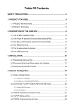
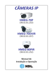
3 VACAM ANPR integration with Ex-Sight’s products
VACAM Remote Viewer Connectivity with VACAM ANPR
Page 7 of 78
User Manual
VACAM ANPR
The Remote Viewer software communicates with Ex-Sight’s major security products: VACAM ANPR and CFAS.
Every connection between the “Remote Application” (VACAM ANPR or CFAS) to VACAM Remote Viewer is
defined as a “Remote Channel".
Note: To quickly set up remote channels based on default values, refer to the section “First Time Usage”.
Every remote channel has 2 TCP/IP ports: the Command Port and the Status Port. Via these ports, the software
communicates with the remote applications. For information about connection setup to remote applications, see
section 3.2. ("VACAM Remote Viewer connection to VACAM ANPR").
The remote application has an Access List (VACAM ANPR), or a Suspect Database (CFAS).
Based on the video source, the application sends alerts to VACAM Remote Viewer. Every alert has 3 components:
1.
Details about an alert in the Access List/Suspects Database.
2.
An image(s) path for an alert:
2.1
One image for an ANPR (License Plate Recognition) alert.
2.2
Two images for a face alert: an image of the currently captured face and an image of the suspect
from the suspect database.
3.
Real-time data about an alert, such as its time, confidence level (in ANPR alerts), or the similarity level
between the current face and the database face (in face alerts).
The above mentioned alerts are received by VACAM Remote Viewer and displayed on the respective remote
channel.
Page 8 of 78
User Manual
VACAM ANPR
3.1 VACAM ANPR Settings tab
Communication Ports
Under the "Settings" tab, find the "TCP Communication Ports" category, which contains the following port
numbers:
2 sets of Command + Status ports: the “Regular In Port” & “Regular Out Port” and “MultiView in Port” &
“MultiView Out Port”. Select to communicate with either of these sets.
“Regular In Port” and “MultiView In Port” are the ports through which VACAM ANPR gets commands from
VACAM Remote Viewer. They correspond with the Command Port in VACAM Remote Viewer
“Out Port” and “MultiView Out Port” are the ports through which VACAM ANPR sends its statuses and alerts to
VACAM Remote Viewer. These ports correspond with the Status Port in VACAM Remote Viewer.
The default values for these ports are as following:
1. In Port =11001 , Out Port = 11000
2. MultiView In Port=13001, MultiView Out Port =13000
For example, it is possible configure VACAM Remote Viewer to work with VACAM ANPR that is installed on a PC
with an IP address = 192.168.2.100 on ‘In Port’ and ‘Out Port’ (instead of the default Multi-View ports):
3. Go to the channel settings (by pressing the channel number on the upper-left corner), and enter
corresponding values as shown on the above screenshot, press the “Apply” button on the bottom-right corner.
Page 9 of 78
User Manual
VACAM ANPR
3.2 Directories
For the alert images to appear on VACAM Remote Viewer, follow these steps:
1. Share the directory of the Annotation Images (located in the settings under the “Directories” category).
2. Set the “Annotation Images Dir.” value to that of the network path of the shared directory.
Note: In case VACAM ANPR and VACAM Remote Viewer run on the same PC, it is possible to set the
“Annotation Images Dir.” value to the physical path of the shared directory (see the image below).
VACAM ANPR “Directories” by default:
The “Annotation Images Dir.” is set to a physical path. Thus alert images cannot be displayed /grabbed by VACAM
Remote Viewer.
In order to allow remote viewer to grab the images from a different PC, follow these steps:
1
2
Share the Annotation Images Directory.
Set the shared network path as the value for “Annotation Images Dir.”.
For example:
After completing this procedure, VACAM ANPR will display alert images.
Page 10 of 78
User Manual
VACAM ANPR
4 Installation Guide
Download the setup from Ex-Sight’s FTP
Extract contents into a desired folder
Run setup.exe
Finish setup
Page 11 of 78
User Manual
VACAM ANPR
5 The VACAM ANPR Activation
Register/activate your product:
Double click on” VACAM ANPR Activation” icon located on your desktop.
The following window will appear:
To receive the license, copy the hardware ID in the box above and send it to Ex-Sight.
After you receive the license file, you will need to copy it to the installation folder.
Do this by clicking on ACTIVATION and then by selecting the received license, or simply by copying the received
license to the application folder “C:\Program Files\Ex-Sight.Com\VACAM_ANPR” by default.
Page 12 of 78
User Manual
VACAM ANPR
6 First time software usage
First Time Usage:
Run VACAM ANPR from the link on your desktop:
The application icon will appear in the notification area (System Tray).
Right click on the icon
to open the context menu in the notification area:
The following functions will be displayed:
Channels: number of licensed channels
Circular storage: enables the user to erase old data according to settings
Run all channels: runs/restarts all channels defined in settings
Settings: enable to define channels
Page 13 of 78
User Manual
VACAM ANPR
Open a new channel:
The “Settings” section displays the number of allowed channels depending on the license type.
The launcher screenshot below displays a 4 channel license.
Choose an empty channel.
Click on the “SELECT SETTINGS LOCATION” button.
Select Settings Location
Select the file “settings.xml” (default on “C:\Program Files\Ex-Sight.Com\VACAM_ANPR”)
Duplicate the settings.xml file (to settings2.xml, settings3.xml, etc).
Note: The duplication of the settings files is necessary because it enables the user to configure every channel
accordingly. For example, channel 1 may handle access control scenario, while channel 2 may handle a
highway scenario.
(!) While it is possible to use the same settings file for all channels, it is not recommended to do that, since
applying /loading/saving the settings in one channel might affect other channels.
Page 14 of 78
User Manual
VACAM ANPR
The snapshot below shows two out of four channels assigned to different setting files:
Once this step is completed, you will be able to use the channel.
Close the settings window and select the channel you have recently set.
All configured channels will be automatically loaded
Once the channels are defined, the DETECTOR CHANNEL ICON (
) will appear.
A right click on this icon will open the following window:
A left click on SHOW (or a double-click on the icon) will display the program’s Main Panel.
Page 15 of 78
User Manual
VACAM ANPR
7 Main Panel Functionalities
Program tabs
Source Area
Current
Detection
History
Area
Real-Time
Notifications
Area
Status Bar
Page 16 of 78
User Manual
VACAM ANPR
7.1 Source Area
In this area you can define a source/multiple sources from which the program will try to detect license plates.
7.1.1 Video Source (VLC)
Play input video button
Select video file location
Clear input & processing queues
Select device and run
Refresh device list
Media Source Path: provides the RTSP Media URL/Stream name of the video source.
Note: The Media URL/Stream name must be provided to you by the manufacturer of the camera.
For your convenience, a file named 'RTSP LIST.xls' has been attached to VACAM ANPR's installation pack (you can
find it under the installation path that is 'C:\Program Files\Ex-sight.Com\VACAM_ANPR\' by default).This file
contains RTSP (Real Time Streaming Protocol) stream names for most of the IP cameras on the market today – use
it to find your camera's stream name.
The table below shows an exemplified list of RTSP values of Samsung cameras:
Example: given is a Samsung model SNB-1000 IP camera with an IP number 10.12.13.111. To use it as a video
source (section 7.1.1), write “rtsp://10.12.13.111/mpeg4unicast” in the Media Source box.
Page 17 of 78
User Manual
VACAM ANPR
Description. A name entered into this field appears on the top of the page and is used to describe a video source
(IP/name/location/etc).
Note: The access list counters will be saved under that description name at “C:\Program Files\Exsight.Com\VACAM_ANPR\Counters\1\<description>.txt”, so for a description like "MyCounters" the counters will
be saved at “C:\Program Files\Ex-sight.Com\VACAM_ANPR\Counters\1\ MyCounters.txt”
Frame ratio: Choose 1 to generate the highest frame rate for the detector to detect. Choosing X says to the
detector to record and process one image out of X images.
For example: for a 25 FPS video source, choosing 2 will generate 12.5 FPS for the ANPR engine to process, while
for a 30 FPS video source, choosing 2 will generate 15 FPS for the ANPR engine to process.
Format of stored picture. May be used to lower stored data space (jpg)/improved picture look (png) using
different picture formats.
The Zoom Factor of input video. The ANPR engine has the ability to make it easier for a lower quality frame to be
detected by using a magnifying algorithm.
Note: Increasing the value to 2 will suffice in case ANPR finds it difficult to detect plates at regular values. The
zoom factor will drastically affect the software efficiency and should be handled with care.
Under DirectX you will find a list of available devices that are directly connected to the PC (via an analog card,
USB, etc.).
Device - a list of devices that are directly connected to the PC.
Resolution - the available resolutions for the selected device.
Show VLC - When this checkbox is checked while pressing the “Play input video” button the VLC video window will
be visible on top of the ANPR channel. In case it will be unchecked it will be hidden at the system tray.
Loop Video – this checkbox must remain marked, as it commands the video player (VLC) to always keep the video
alive (even after abrupt network disconnections).
Note: Unmarking this checkbox when using a live video source will stop the video frames arrival upon any kind of
network disconnection.
When playing a video file, keeping the checkbox checked will play the video from the beginning when it finished
playing.
Page 18 of 78
User Manual
VACAM ANPR
7.1.2 Still Images Source
Execute on selected list of files
Clear files list
Add Files to list
Image Files
(Still Images)
List
Load files from directory
Note: This functionality enables you to manually add image files to the files list as well and detect license plates
extracted from those images. It is fit for real-life usages (e.g. by parking supervisors). Besides, it serves as a
calibration tool.
Calibrating example: Take an image/ images of a vehicle and alter its topographic parameters to create the best
license plate detection scenario.
Page 19 of 78
User Manual
VACAM ANPR
7.1.3 Snapshots Source
Shows trigger settings of selected snapshot device
Starts Snapshot Sequence on selected device
Configured Snapshot Devices
Stops Snapshot Sequence on selected
device
Clears input & processing
queues
Selected Snapshot Device Settings
Manually operated snapshot devices
A snapshot device is configured under the settings tab (General->Triggers - section 10.1.17 “Triggers”). Usually a
snapshot device is associated with a trigger, so when the trigger fires, the
snapshot sequence begins.
View the FPS ratio of each snapshot device in real-time as shown on the
right->
You can also Start/Stop the selected snapshot device sequences via the relevant buttons as mentioned above.
Page 20 of 78
User Manual
VACAM ANPR
7.2 Real time Notifications Area
View real-time video frames arriving from the video source (VLC or a snapshot device), and as well the plates
currently held in the Filter List (and their time of arrival).
Press the “Clear List” button to clear the Filter List.
For more information, see the Filter List settings (Under General Settings> Detection - section 10.1.5).
Live Video Frames
Plates to be filtered
Page 21 of 78
User Manual
VACAM ANPR
7.3 Current Detection History Area
Current
Detection
Details
Current Detection Image
Open PTZ Panel
Mask on/off (Left-click) +
Masking options (Right-click)
First/Last detection
Clear detection list
Next/Previous detection
Recent Detections Grid
View recent VACAM ANPR channel detections (the maximum rows in this grid can be configured under the
Settings Tab: General->Graphic User Interface, section 10.1.8).
Note: This area shows detections only if the “Refresh History on Data Arrival” checkbox is marked. Otherwise,
detections will only be logged and send via TCP to clients, with no changes to the User Interface (UI) in order to
save CPU & memory resources. Unmark this checkbox once you have finished calibrating the channel (unless you
need VACAM ANPR to view live detections).
Page 22 of 78
User Manual
VACAM ANPR
ANPR detections are marked as follows:
Green: Approved List
Yellow: Unidentified
Red: Black List
Page 23 of 78
User Manual
VACAM ANPR
7.3.1 PTZ (Pan Tilt Zoom) Panel
To open the PTZ (Pan Tilt Zoom) panel, click on the
icon.
The panel below will appear.
Use this panel to calibrate the video source manually, or to record/play a PTZ script that can be fired at a specific
time of day.
For more information about PTZ control, see section 12 : Appendix B: “PTZ Control”.
Page 24 of 78
User Manual
VACAM ANPR
7.3.2 Masking options
To view/change the masking options, right-click on the mask icon (as seen on the
right).
Under Mask Editing, select the displayed mask type (Image/Rectangle) which
appears on top of the video and the Current Detection Image.
Under Applied Mask, view the mask type which is currently in use by the ANPR
detector.
Under Change Mask Type, change the mask that will be applied onto the ANPR
detector (press Apply following your selection).
While editing a mask, you can click on Show Edited Mask to see the mask being
edited (and not applied yet). To see the mask being applied onto the ANPR
detector, click on Show Mask In Use.
Rectangle Mask Editing
When editing the rectangle mask for the first time, you may encounter the
following message on the right:
Note: The mask size is not available, as no frames are available from the video
source. To enable the program to obtain the frame size, connect to your video
source for a few seconds.
After the program has obtained the frame size, click on Edit Rectangle Mask to mark the desired mask (by clicking
on the top-left and bottom-right corners):
After marking the top-left corner and the bottom-right corner, click Save Rectangle Mask to save the mask and
apply it onto the detector if necessary.
Page 25 of 78
User Manual
VACAM ANPR
Image Mask Editing
During initial image mask editing, the following
message might appear:
Clicking “yes” will enable you to select an image
from the “Annotations Directory” or any other
image of the same size as that of the video frames.
Independently of what you click: ‘Yes’ or ‘No’, the Image Editor (see General settings > Mask, section 10.1.9) will
open.
Then 2 categories will be displayed:
1. The image mask
2. The image from the annotations/detections directory (if found).
See the example below:
Page 26 of 78
User Manual
VACAM ANPR
To create a mask in the image editor, put the annotation/detection image as the background layer, and put the
mask layer on the top. Then mark masked areas in black, while leaving unmasked areas transparent (see the
snapshots below):
Delete
Layer
Then delete the layer of the annotation/detection image (like the snapshot above, on the right) and save the file
(Select auto-detect at Bit Depth) to complete the process.
For detailed information about masking, refer to section 10.1.9 “Mask”.
Once you have saved the mask file to its original file name, press “Refresh Image Mask” to see the mask you have
just created.
In case the selected mask is of the “image” type, the image mask will also be re-applied on the detector:
Page 27 of 78
User Manual
VACAM ANPR
7.4 Status Bar
PTZ:
A left click on this icon opens the PTZ control panel.
Triggers Indicator:
Trigger (of digital input) statuses: when one of the defined triggers is activated, the icon turns yellow (
).
Access List Length:
Current number of license plates on the access list
Relays:
Relay COM( )
Relay connected directly to a PC via USB or COM Connector.
When the relay circuit is closed (e.g. if the gate is open), the relevant relay number is colored green.
When the relay circuit is open, it is colored red.
Relay IP( )
Relay connected via network.
When the relay circuit is closed (e.g. if the gate is open), the relevant relay number is colored blue.
When the relay circuit is open, it is colored purple.
Note: The relay numbers that lit up are the IDs associated with the
relevant AL, BL, and UI relays. See sections 10.1.12 “Relays (COM)” & 10.1.13 “Relays (IP)” for more
information.
Page 28 of 78
User Manual
VACAM ANPR
COM Relays Menu:
Open Gate: Sends a pulse to the relay to open the
relevant gate (AL/UI/BL) and to close it within a
certain period of time as defined in the settings.
Alert check: Sends alerts if cables are disconnected.
Temp. Blocked: Blocks opening/closing commands
regardless of their source. When blocked, the
following icon appears -> .
Connect to Relay: Connects to the COM relay.
Open Circuit/Close Circuit: Sends a pulse to the relay
to open/close the relevant circuit (AL/UI/BL).
Enable/Disable: Automatic gate opening after detection.
IP Relays Menu:
Open Gate: Sends a pulse to the relay to open the
relevant gate (AL/UI/BL) and to close it within a
certain period of time as defined in the settings.
Temp. Blocked: Blocks opening/closing commands
regardless of their source. When blocked, the
following icon appears ->
Test NVC Relay Connection: Performs connectivity
check-up.
Triggers: Displays the list of defined triggers
connected to NVC.
Reconnect NVC Triggers: Reconnects to the NVC
trigger devices.
Reconnect BF Device: Reconnects to the BF device.
Open Circuit/Close Circuit: Sends a pulse to the relay to open/close the relevant circuit.
Enable/Disable: Automatic gate opening after detection.
Page 29 of 78
User Manual
VACAM ANPR
Video Frame Q current size
Burst Q current size
Video Q’s (Video Queues):
Two types of queues are used by the system:
The Burst Queue and the Video Frame Queue
The Queues icon ( ) shows which of the queues is enabled at the current time:
No queue is enabled (typically happens when the processing trigger is turned off). This is indicative of
the following:
Images from the video source are being ignored.
The application Video Frame Queue is not forwarding its frames to the engines to be processed.
Burst Queue is enabled. This is indicative of the following:
Images from the video source are being forwarded.
The application Video Frame Queue is not forwarding its frames to the engines to be processed. (This is a
rarely used combination)
Burst Queue is disabled. This is indicative of the following:
New images from the video source are being ignored
The application Video Frame Queue is enabled. This means that the application Video Frame Queue is
forwarding its current frames to the engines to be processed. (This is a rarely used combination).
Both Queues are enabled. This means that frames that arrive from the video source are being
received, forwarded to the Video Frame Queue, and further to the engines to be processed.
A click on the Queues icon ( ) will toggle it to enable ( )/disable ( ) the queues
A click on the ‘Burst Q current size’ will display the current size and the queue overflow information. For more
information about the Video Queues, see Appendix A : ‘VACAM ANPR Detection Process, Queues & Actions’
(section 11)
Engines:
Gives the number of concurrent processing units (“engines”) in the system and presents each engine’s
current processing queue count.
FPS:
Shows the total number of frames extracted from the video source(s) per second.
Counters:
Displays the counters of Black List/Unidentified List/ Access List license plates
About:
Displays the application details.
Page 30 of 78
User Manual
VACAM ANPR
8 Access List Tab
General description:
The Access List is a CSV file configured under the VACAM ANPR applications. It can be opened, edited or changed
by VACAM ANPR, Excel, or any other software fit for CSV files.
The Access List file includes 2 mandatory fields:
1. The “License Plate Number” (must be the first one) contains the license plate number (may include
letters).
2. The “Blacklist” field (must be the second one) contains the Boolean value (‘True” or “False”) of the license
plate marking:
If marked as ‘Black List’ > True
If marked ‘Access List’ > False
Other fields may also be added to the access list (e.g. the driver’s name and ID). The chosen fields will be logged
upon each detection and sent via TCP to connected clients.
Main Functionalities:
Enable Access List:
If this check-box is unmarked, the system will not perform an access list comparison and all detections will be
tagged as “Unidentified".
Load /Save list/ Save as:
Contains commands to load/save the access list
Load Save Save As
Usage:
Any piece of data from the Detection Grid, as well as from other locations, can be copied to any Access List
data field ( Ctrl+C –Ctrl+V). The data may include the list of the company’s visitors or unwanted persons,
etc.
Notes:
Any piece of data in the Access List can be saved for future use.
The License Plate field must not (!) contain duplicate values.
Page 31 of 78
User Manual
VACAM ANPR
9 History Tab
To start viewing daily history reports, select a day from the list (marked in red).
Page 32 of 78
User Manual
VACAM ANPR
9.1 History Tab options
(A)
Detection day – a daily list of
detection logs – select a day from
the list to view the detection log of
that day.
(D)Import Detections (E)Search
(F)Row count
(A)Detection day
(G)Row description
(B)Refresh
(C)Font Size
(B)
Refreshes the daily list of detections
logs.
(C)
Increases/decreases the font size on
the row description panel (G).
(D)
Enables you to import detections
from the detections log file (CSV –
the native format of VACAM ANPR
detection logs, or MDB).
(E)
Allows you to search the selected detection log. Opens the following panel:
(I)Detections
Grid
(H)Detection image
Hide Search
panel
Advanced Search
Search
Search box
Field
button
In simple search, select the field
to search and find rows that have similar text in the selected field.
When you press on “Advanced”, the following panel will appear:
Operator 2
Field
Operator 1 Logic
condition
type Here you can refine
the search by defining the field type: Text (default), Number, or Date/Time. Then you
can select 1 or 2 operators and a logic condition (AND or OR) to base the search on.
(F) The row count (Shown rows out of/Total rows in detection log)
(G) The content of the selected row
(H) The detection image.
(I) The detection grid where all the rows of the detection log are presented.
Page 33 of 78
User Manual
VACAM ANPR
9.2 Log display & Search example
Example: Search of detected license plates on the detection log dated 7.4.2011
The detection’s confidence level (CONFIDENCELEVEL) equals 3.
The right top window displays the details from the selected row:
To open an image intended for use in external software (like a picture viewer), double-click on the Image
Location:
Page 34 of 78
User Manual
VACAM ANPR
10 Settings Tab: Advanced User Settings
General Settings Section
Engine Settings Section
PTZ Scripts Section
Page 35 of 78
User Manual
VACAM ANPR
10.1 General Settings Section
10.1.1 Access List
Access list file:Access List files (csv).
You can load/save Access Lists from the Access List tab.
For more information on how to change the access list, turn to section 8 (“Access List Tab”).
Enable access list: Enable/Disable the use of the Access List:
If you do not have any need in using the access list alert, you can turn it off.
10.1.2 Automatic Video Start
Enable automatic video start: Enable/Disable automatic video start.
Turning this option on starts the VLC video source automatically and eliminates the need to click “play” every
time the channel starts. In case constant video (VLC) serves as a video source and there is no human operator,
this value must be set to “true” after calibration.
10.1.3 Channel Information
Channel description: User defined name of the channel.
The default name is 127.0.0.1 (the local host).
The default name from the Media Source field will be automatically converted into the IP address of the video
source (camera, etc) and will be found in the Channel Description field.
This helps the user keep the channel’s location/use/purposes better described and organized.
This is important in case you have many channels/cameras/video sources to be distinguished from one
another.
Note: Channel description appears in the channel title, as well as in the tooltip of the channel on the system
tray.
10.1.4 Country Code
Country code: The country code of the plates that VACAM ANPR tries to detect.
Note: It is very important for the ANPR detection to identify the type of plate. It should be set by the user to
the correct value in order for the VACAM ANPR to work properly.
Country Code for Auto Correction:
When “Auto Correction” is enabled in Engine Settings, the program will correct the plates according to the
country code provided here.
Page 36 of 78
User Manual
VACAM ANPR
10.1.5 Detection
This category contains the detection mistakes criteria (‘Allowed number of mistakes’) and the Filter List.
Allowed number of mistakes: the number of allowed mistakes in plate detection vs. the access list.
Changing this value will change the strictness of the comparison between the detected plate vs. the plate
from the access list (0 is the default value which allows no mistakes).
Example: Given is the following plate from the Access List (marked as “AL”) “CZ889KT”:
The program is currently detecting the plate “CZ889KF”. In case “Allowed number of mistakes”=0, this
detection will be marked as “Unidentified” (UI), as the plate from the access list differs in one character
from the currently detected plate (the last character is T vs. F).
To get an alert for this plate, set the “Allowed Number of Mistakes” to 1 (one character variation). Then
the detection will be marked as “Access List” (AL).
Length of Filtered Plates List :
The filtered plates list (see 7.2 “Real time Notifications Area”) is a list of plate numbers and the last time
they appeared. When a plate is detected, it is matched to the filter list. In case of a match, the plate is
filtered, and thus no action is performed by the program (the detection is only logged locally, but not
transmitted as an alert).
Change this value to change the length of this list.
Example: In case the license plate above is detected once, while the value of the “Length of Filtered Plates
List” is 1, the detection will appear on the detection list, but it will not display the same plate again unless
another plate is detected.
If the value is 2, the plate above will first appear and then be filtered until 2 different plates are detected.
Note: Using this feature helps avoid unnecessary repetition of identical license plates.
Remind about filtered license plates:
When set to True, only the plate’s first detection is registered on the filter list. After “Seconds to Filter
Repeated License Plate” elapses, an identical filtered plate can be detected and command the program to
perform respective actions, e.g. open the gate according to the alert type.
When this value is set to False, each detected plate will be saved to the filter list with the time stamp. This
means that if several identical detections have occurred with time gaps smaller than “Seconds to Filter
Repeated License Plate”, the detected license plate will appear only once(the rest of the times it will be
filtered).
For more information, see “Length of filtered plates list” and “Seconds To Filter Repeated License Plate”.
Seconds To Filter Repeated License Plate:
The number of seconds the repeated license plate is considered to be filtered – in this time period the
program will not perform any actions for that plate, besides logging the detection to the HD.
Example: The situation: this value is set to 10 seconds, while the value of “Length of Filtered Plates List” is
set to 1, and the license plate “12-123-12” is detected twice. If the last detection occurs within less than 10
seconds from the first, it will be filtered by the program.
Show filter list: Shows/Hides the filter list that consists out of 2 fields: the filtered license plate and the
time it was last detected.
Page 37 of 78
User Manual
VACAM ANPR
10.1.6 Directories
Annotation Images Dir.:
This directory stores the all the detections images: the video frames containing the captured plate and text
annotations providing the detection details. (Detection details are displayed in the “History Tab”.
For more information about the history tab, see the “History Tab”, section 9 ).
Counters Dir.:
Counter files contain the recent counting of any alert type (BL/UI/AL).
Changing the channel’s description changes the counter’s file name thus zeroing all the counters.
The counters are displayed on the status bar, as shown below.
Detection Images Dir.:
Containing new images to be stored until they are processed by the ANPR detector.
Detection Log Dir.:
Contains detections logs displayed in the History Tab (section 9).
A detection log contains image paths, confidence levels, detection time, and license plate numbers:
O533944
C:\Program Files\Ex-Sight.Com\VACAM_ANPR\AnnotationImages\img_O533944_634353683623301617.jpg
1
4.431253
O533955
C:\Program Files\Ex-Sight.Com\VACAM_ANPR\AnnotationImages\img_O533955_634353683649503115.jpg
1
1.357078
533201
C:\Program Files\Ex-Sight.Com\VACAM_ANPR\AnnotationImages\img_0533201_634353683649623122.jpg
1
2.683154
533202
C:\Program Files\Ex-Sight.Com\VACAM_ANPR\AnnotationImages\img_0533202_634353683683565063.jpg
1
1.699097
3320465
C:\Program Files\Ex-Sight.Com\VACAM_ANPR\AnnotationImages\img_3320465_634353683714136812.jpg
1
4.690268
1970032
C:\Program Files\Ex-Sight.Com\VACAM_ANPR\AnnotationImages\img_1970032_634353683742378427.jpg
3
3.047174
9700322
C:\Program Files\Ex-Sight.Com\VACAM_ANPR\AnnotationImages\img_9700322_634353683757849312.jpg
1
2.933168
Network Path Validator Enabled:
Determines whether or not to use the network path validator in order to ensure that the paths that are
provided are available, and if not set them temporarily to the default location that lies on the hard drive ,
until the paths are avilable again (in that case the original paths will be restored).
By setting this value to “True”, you ensure that there will be no loss of valueable information (all the
detections will be logged, either in the original network path, or on the local default path that lies on the
hard drive).
Network Path Validator Interval (sec).
The interval (in seconds) to pass between consecutive path verifications(the interval might get bigger
when paths don't exist - might get up to ~6 minutes of delay) if all paths are invalid network paths.
PTZ Scripts Dir.:
The PTZ scripts directory
Page 38 of 78
User Manual
VACAM ANPR
10.1.7 Engine Settings
LPR Config Filename: ANPR Configuration Filename to use:
The user needs to create for each channel he has a deferent file in order for the settings to be separate for
each channel.
The default path of the lpr.xml is “C:\Program Files\Ex-Sight.Com\VACAM_ANPR\lpr.xml”
Minimum confidence level: Minimum confidence level(5 is poor, 1 is excellent)
The confidence level value will determine how accurate the user wants the detected plate numbers to be in
equivalent to the original plate.
Choosing low confidence level will produce more detections while high confidence produces a more quality
detection with higher chance of a correct detection.
Number of engines: Number of ANPR engines to use.
VACAM ANPR support multi threading. Users with multi processor units can set the engines numbers to the
amount of cores.
Example: choosing 2 for 2 cores CPU and 4 for a 4 cores CPU.
Page 39 of 78
User Manual
VACAM ANPR
10.1.8 Graphic User Interface
Max. Allowed Rows in the Detection Grid: Maximum allowed number of rows in the Detections Grid.
The grid's behavior: FIFO (First In First Out).
Example: Given are 5 detected images (enter order = older<- 5 4 3 2 1 ->newer). The max allowed of rows in
the detection grid is set to 5.
On next detection, the oldest images will be cleared from the grid and picture will take its place (older 4 3 2 1
X newer).
When a new license plate arrives, the previous one is automatically dragged down.
Refresh history on new data arrival:
When set to true, the newly detected plate is displayed upon detection. This functionality is reflected in the
corresponding checkbox on the Main Panel (marked red on the screenshot above).
Note: The default value is “False” (for efficiency). Therefore, when you first calibrate the channel to see
detections as they appear, you must set this value to “True”. Otherwise, it seems that the program is not
detecting plates while it actually is.
Page 40 of 78
User Manual
VACAM ANPR
10.1.9 Mask
Image Editor exe path: The full path to the Image Editor exe file. Recommended software : Paint.net (you can
get it free at http://www.getpaint.net/, help documentation is available at http://www.getpaint.net/doc/latest/)
Image Path: The Path to the Mask Image (PNG, grayscale) : masked areas in the image should be Black - and
all the rest should be Transparent(for exact color definition see below).
To use the Image Mask set 'LPR Mask: Type' to 'Image'.
Notes:
Mask Image should be the same size as the received
video frame size! (Otherwise the mask will not work
properly, as the masked areas will not be correlated
with the actual video).
The ARGB (Alpha Red Green Blue) definition for Black
is ARGB (255,0,0,0), meaning that the alpha level is
255 and the rest of the values are 0(as can be seen on
the right in the Paint.net Colors window).
The ARGB definition for Transparent is ARGB(0,0,0,0),
meaning that all the values are 0.
On Video Opacity: The Opacity of the On Video Mask (ranging from 0 for full transparency to 255 for full
opacity)
Note: This property is relevant only when “Show on Video” is ‘True’.
Rectangle: The LPR Rectangle Mask. To use it, set 'LPR Mask: Type' to 'Rectangle'.
Rectangle Image Path: The Path to the Rectangle Mask Image (in most cases should not be changed).
Show on Video: Show the Mask on the Video Source (is relevant only for VLC video source).
Type: The LPR Mask type: None/Image/Rectangle.
Page 41 of 78
User Manual
VACAM ANPR
10.1.10 PTZ Control
Baud rate: Baud Rate for the PTZ controller
Device address: PTZ Device Address accessed
IP address of the PTZ device (if any): IP Address of the PTZ device (if exists).
Connection Type must be 'SerialOverIP' for this to work
Port number of the PTZ device (if any): Port Number of the PTZ device (if exists).
Connection Type must be 'SerialOverIP' for this to work
PTZ com port: COM port of the PTZ controller
PTZ connection type:
Direct COM: the PTZ controller connected directly to this machine (via USB or COM port).
Serial Over IP: the PTZ controller located on a remote device (Commands are transmitted over the network
connection).
PTZ protocol: PTZ Protocol used, depending on the support protocol of your device.
Script scheduler check interval: The interval to pass (in seconds) between successive checks of the script
scheduler table
Note: Low values will generate better accuracy during the script execution time but will slow the program
down.
Script scheduler filename: Specifies The PTZ script scheduler filename path.
10.1.11 Queues Management
Clear Q’s on AL Plate: Clears the Processing Queues upon the detection of an AL (Access List) Plate
Clear Q’s on BL Plate: Clears the Processing Queues upon the detection of the Black List Plate
Clear Q’s on UI Plate: Clears the Processing Queues upon detection of an UI (Unidentified) Plate
Page 42 of 78
User Manual
VACAM ANPR
10.1.12 Relays (COM)
Settings for a relay connected to the PC via USB or COM port
Double Pulse Automatic Close: Closes the gate automatically by sending a pulse for opening the gate and
then, after X seconds, sends the same pulse (close circuit) to close the gate.
Double Pulse Automatic Close (Seconds): Time interval X to wait before closing the gate.
Internal Circuit Delay (seconds): Time interval during which the circuit of the relay is closed.
Relay Number -> Blacklist (BL): Relay number for 'Blacklist'(BL) detections.
Relay Number ->Identified (AL): Relay number for 'Identified'(AL) detections.
Relay Number -> Not identified (UI): Relay number for 'Not Identified/Unidentified'(UI) detections.
Relay Enabled: Enable/Disable the use of the relay controller.
Relay Port: The COM port of the relay controller.
Page 43 of 78
User Manual
VACAM ANPR
10.1.13 Relays (IP)
Authentication: Enabled: Enable/Disable IP Relay commands authentication (by “Authentication: Username”
and “Authentication: Password”).
Note: Authentication is applicable in the NVC/HDIR Cameras/Encoders. If you are using an HDIR camera, the
Username & Password must be correct in order for the relays to work, even if this value is set to False.
Authentication: Password: Edge device password.
Authentication: Username: Edge device username.
BF Model Type: ‘IP Relay Model’ must be set to ‘BF’ for this to have effect.
BF Model: Auto Reconnect: When set to True, the program will attempt to reconnect to the BF device in case
of a timeout.
BF Model: Check Status Interval (ms): The time interval for checking the status of the BF device (in
milliseconds)
Note: This value must be lower than the Response Timeout (at least by 100 ms).
IP Relay Model: Determines the IP Relay Model type.
Relay IP Address: The remote relay IP address.
Relay Number-Black List (BL): The relay number for “Blacklist” (BL) detections. Enter -1 to disable.
Note (1): NVC Relay numbers start from 0.
Note (2): HDIR Relay number must be 0 in order to take effect.
Relay Number-Identified (AL): The Relay number for “Identified” (AL) detections. Enter -1 to disable.
Note (1): NVC Relay numbers start from 0.
Note (2): HDIR Relay number must be 0 in order to take effect.
Relay Number –Not Identified (UI): The relay number for “Not Identified/Unidentified (UI)” detections: Enter1 to disable.
Note (1): NVC Relay numbers start from 0.
Note (2): HDIR Relay number must be 0 in order to take effect.
Relays command Port: The HTTP command port of the IP Relay.
Relays Enabled: Enable/Disable the use of IP Relays.
Relays Timeout (sec): The time period (in seconds) to leave the relay On before switching it Off when the relay
is pulsed.
Response Timeout: The edge devices’ response timeout.
Note: For BF devices, the default value is 1500ms (should be higher than ‘The BF Model: Check Status
Interval’).
For other devices, the default value is 5000ms (should be higher than 1000 ms).
10.1.14 Security:
Login: Enable: Commands whether or not to display the Login Screen upon the user’s request to show the
application.
Login: Password: The login password.
Login: Username: The login username.
Note: The default username & password are “root: pass”.
Page 44 of 78
User Manual
VACAM ANPR
10.1.15 Storage Settings
Circular Storage is a timed operation that deletes all old data (“Old data” is defined by the properties below).
Circular Storage is important if you intend that program runs with minimum user intervention, since the
program will malfunction if the HD does not have enough space. These properties must be set to values
adjusted to your needs:
The number of days during which you wish to save the data
PC limitations (e.g. the hard drive space available)
Circular Storage Days (Annotations): The number of days in storage for annotation Images.
Note: Enter 0 to disable the circular storage for this data (notice that in this case images will never be
deleted!).
Circular Storage Days (Detection Logs): The number of days in storage for the Detection Logs (that can be
seen in the history tab).
Note: Enter 0 to disable the circular storage for this data (notice that in this case detection logs will never be
deleted!).
Detections Circular Storage Minutes: The number of minutes in storage for detection Images (the images that
emerge from the video source and are processed for license plates detection).
Example: in case the value is 15, images older than 15 minutes will be deleted.
Enable Circular storage: Enable/Disable Circular Storage.
Note: Disabling the Circular Storage will cause the application to store data on the hard drive without ever
deleting it, which may cause the program’s malfunction.
Page 45 of 78
User Manual
VACAM ANPR
10.1.16 TCP Communication ports
VACAM ANPR contains 2 sets of TCP ports, through which the communication between VACAM ANPR and
external programs (e.g. VACAM Remote Viewer), is maintained:
MultiView ports (default ports for VACAM Remote Viewer)
Regular Ports
Every set is comprised of In port (to receive commands) and Out port (to output alerts, statuses, etc.)
MultiView In port: MultiView TCP Incoming Port.
MultiView Out port: MultiView TCP Outgoing Port.
Ports Ack. Timeout (sec.): The timeout (in seconds), after which the program stops waiting for
acknowledgements from remote software and restarts MultiView Communication (minimum 11 seconds).
MultiView Ports API Version: The API Version used in the communication of the MultiView Ports.
MultiView Ports Wait for Acks.: Determines whether MultiView ports will wait for acknowledgements from
the ANPR channel. In case no acknowledgement is received, communication will be restarted.
Regular In Port: Regular TCP Incoming Port.
Regular Out Port: Regular TCP Outgoing Port.
Regular Ports Ack. Timeout (sec.): The timeout (in seconds), after which the program stops waiting for
acknowledgements from remote software and restarts Regular Communication (minimum 11 seconds).
Regular Ports API Version: The API Version used in the communication of the Regular Ports.
Regular Ports Wait for Acks.: Determines whether Regular ports will wait for acknowledgements from the
ANPR channel. In case no acknowledgement is received, communication will be restarted.
Page 46 of 78
User Manual
VACAM ANPR
10.1.17 Triggers
Triggers enable the program to detect license plates only when necessary (as opposed to constant detection from
video).
Below is the example of ANPR trigger deployment:
Trigger Line
Camera
Stop Line
To Add/Remove/Change Triggers Settings, follow these steps:
Open Triggers Settings
The following dialog will appear :
Configured
Triggers
Trigger Settings
Trigger type to be added
Add/Remove trigger
Page 47 of 78
User Manual
VACAM ANPR
After adding a trigger the “Trigger Settings” section will show the newly added trigger settings:
10.1.17.1
BF Trigger
Digital Input #: The number of the Digital Input (DI).
Note: In order to use BF triggers 'Relays (IP) ->IP Relay Model' must be 'BF'.
10.1.17.2
NVC Trigger
Select and add “NVC Trigger” in the “Trigger Type”. The following window will appear:
Mask Value Trigger Off: The mask value that signals that the trigger is off (0 by default when dealing with a
single DI device).
Mask Value Trigger On: The mask value that says that the trigger is on (1 by default when dealing with a single
DI device).
Page 48 of 78
User Manual
VACAM ANPR
10.1.17.3
Snapshot Settings
The Snapshot Settings inform the program as to what type of Snapshot Sequence to attach to each Trigger
Settings (the snapshot device type, the address, the timeout, etc.)
You can use/test the snapshot devices manually, without the physical triggers as seen in section 7.1.3 “Snapshots
Source”.
Authentication:Password: The Password to be used for login(when required) - may be blank when the device
does not require credentials to retrieve snapshots.
Authentication:Username : The Username to be used for login(when required) - may be blank when the
device does not require credentials to retrieve snapshots.
Device Type : When set to HDIR 'Resolution' and 'Quality' are not relevant and pre-determined within the
device (within the selected ‘Snapshot Profile Number’).
HTTP Port: The HTTP port used for communicating with the device (80 by default).
IP Address: The IP Address of the device (camera/encoder).
Off Trigger Stops Sequence: Allow/Disallow from the 'Off' Trigger to end the sequence.
Quality: The Quality of the snapshot that is taken for every event/alert (0-100).
Note: Not Relevant for HDIR device type.
Resolution: The Resolution of the snapshot that is taken for every event/alert.
Note: Not Relevant for HDIR device type.
Sequence FPS: The Snapshot Sequence FPS(Frame Per Second)
The higher this value is, you have better chance of capturing the plates out of the video(the faster the cars
move, you need more FPS) – but at the same time, the CPU works harder, so setting this value should be
handled with care while calibrating the channel and seeing the actual video that the channel should process.
Sequence Timeout (sec.): The Snapshot Sequence Timeout (in seconds).
When set to 0 the sequence will end only upon an 'Off' trigger (in case ’Off Trigger Stops Sequence’ is true,
otherwise it will never stop).
Note: Setting this value to 0 while setting ’Off Trigger Stops Sequence’ to ‘False’ actually makes the snapshot
device to be a constant video source, because when the trigger will trigger once, it will keep bringing frames to
be detected until the user will actively press on the ‘Stop’ button (as described in section 7.1.3 “Snapshots
Source”.
Single Frame Only: ‘True’ ->Take only one snapshot instead of taking a snapshot sequence.
Page 49 of 78
User Manual
VACAM ANPR
o
o
o
o
Snapshot Profile Number: Relevant for the HDIR devices - the Video Profile Number to be used when taking
the snapshot (includes Resolution & Quality).
Note: To go to the HDIR profile settings go to Setup->Image->Audio and Video – there you will find VIDEO
PROFILE 1 and VIDEO PROFILE 2 – adjust them to fit your needs, and then select one of them here(by typing 1
or 2).
Storage&Process Options :
ProcessOnly: The fastest way to get the LPR detection
Not saving the raw snapshot to HD.
Needs extra memory for snapshots.
StoreOnly: Snapshots are only stored and not processed.
StoreAndProcessFromMemory: Fast LPR detection
Saving the raw snapshot to HD
Needs extra memory for snapshots.
StoreAndProcessFromHD: Slower LPR detection.
Saving the raw snapshot to HD
Does not need extra memory for snapshots
Note: Snapshots will be saved to the 'Detection Images Dir.'
10.1.17.4
Trigger
In this category you will find all the settings that make out the trigger and its behavior.
Device HTTP Port: The trigger device HTTP Port (by which commands are passed to the device).
Note: Relevant only for NVC triggers.
Device IP: The trigger device IP.
Device TCP Port: The trigger device TCP Port (by which the trigger events are received).
Note: Relevant only for NVC triggers.
Is COM Relay Prevention Trigger? : When set to true the trigger will cause the COM Relay to block/unblock
according to the trigger status (an ‘On’ trigger will block the relay, while an ‘Off’ trigger will unblock it) - when
the relay is blocked, it won't be allowed to open or close. See section 7.4 “Status Bar”-> ‘COM Relays Menu’->’
Temp. Blocked’ for more details.
Is IP Relay Prevention Trigger? : When set to true the trigger will cause the IP Relay to block/unblock
according to the trigger status (an ‘On’ trigger will block the relay, while an ‘Off’ trigger will unblock it) - when
the relay is blocked, it won't be allowed to open or close. See section 7.4 “Status Bar”-> ‘IP Relays Menu’->’
Temp. Blocked’ for more details.
Is Processing Trigger? : When set to true the trigger will cause the LPR detection to Start/Stop processing
according to the trigger status (‘On’ to start, ‘Off’ to stop). See section 7.4 “Status Bar”-> ‘Video Q’s (Video
Queues)’ for more details.
Is Snapshot Trigger? : When set to true the trigger will cause the program to get a snapshot sequence from
the camera (the sequence frame rate, duration, etc. can be configured under 'Snapshot Sequence Settings').
Trigger Name: The Trigger Name.
Use Trigger? : Enables/Disables the trigger.
Page 50 of 78
User Manual
VACAM ANPR
10.1.18 Video Frames Queue
Dequeue Percent: The percentage of elements to be removed from the queue when the limit is reached.
Set to 100 if you want to clear the queue in such case.
Example: The “Dequeue percent” is set to 10 percent:
In case the queue reaches its limit, 10% of the old images will be removed from the queue and will not be
processed.
Queue Limit: The limit of the queue: when reached, a percentage (defined by 'Dequeue percent') of the queue
is removed.
Report interval (ms): Interval to pass between subsequent file reporting from the Video Frames Queue to the
Engines Queues.
Use threading: Determines whether or not to use multi-threading for pushing the video frames of this queue
to the engines queues. When set to True frames will be brought to the engines queues faster, but unordered.
For more information, see Appendix A: “VACAM ANPR Detection Process, Queues & Actions” (section 11)
Page 51 of 78
User Manual
VACAM ANPR
10.1.19 VLC Settings
Listed below are the properties that ensure proper VLC functioning (for most PCs default values work ok).
For more information, see Appendix A:”VACAM ANPR Detection Process, Queues & Actions” (see section 11)
Burst frames queue: Dequeue percent: Percentage of queues to be removed when the limit is reached.
Set this value to 100 if you wish to clear the queue.
Burst frames queue: queue limit: Queue limit
When reached, the percentage (defined by 'Burst Frames Queue: Dequeue percent') of the queue is removed.
Burst frames queue: report interval (ms): Interval to pass between subsequent file reporting from the Burst
Queue to the Video Frames Queue.
Burst frames queue: use threading: Determines whether or not to use multi-threading for extracting the
frames out of the Burst Queue. When set to True, frames will be brought to the Video Frames Queue faster
but unordered.
Caching Value (ms): Caching value for the media source. Low values will make the video arrive faster (shorter
delay) but might cause the video to be unsmooth or even cause it to stop.
Enable VLC log: Set this value to true only when you have a problem with the VLC player. Otherwise, set it to
false to get overall better performance.
Ensure video ok interval (ms): The time interval (in milliseconds) to pass between subsequent checks that the
video is OK.
Note: if this value is set to less than the time it takes to connect to the camera, the video might never return.
Frame ratio: Frames Per Second (FPS) =25/Frame Ratio.
Note: According to 25 FPS video source.
For more information about this refer to section 7.1.1 – “Video Source (VLC)”.
Image format: Recommended formats: jpeg or png
Loop video: Determines whether or not to loop the video when it reaches the end.
Recent streams history filename: The Filename of the file that holds the history of recently used streams.
Recent streams history save limit: The limit to the number of recent stream strings to be saved.
Note: Changing this property will clear the history.
Refresh system tray: Refreshes the system tray to delete unwanted VLC Icons.
*Important note: settings this value to true may cause instability of the VLC software. Use it only after you
have successfully tried it before.
Page 52 of 78
User Manual
VACAM ANPR
Show VLC player: Determines whether or not to display the VLC Player
Source string: The source string for the VLC player
VLC exe path: The full path to the vlc.exe file
Zoom factor: The image Zoom Factor
Page 53 of 78
User Manual
VACAM ANPR
10.2 Engines Section
10.2.1 Alpha-Numeric Characters
Maximum Alpha-Numeric Characters: Select the maximum number of alpha-numeric characters in the license
plate. License plates that are longer than this number will be ignored.
Note: This property must be bigger or equal to ‘Minimum Alpha-Numeric Characters’.
Minimum Alpha-Numeric Characters: Select the minimum number of alpha-numeric characters in the license
plate. License plates that are shorter than this number will be ignored.
Note: This property must be smaller or equal to ‘Maximum Alpha-Numeric Characters’.
10.2.2 Character Height
Maximum Character Height (px): Maximum character height of the license plate (in pixels).Affects the
detector’s search pattern, and hence affecting the performance – if the detector needs to search for license
plates that are bigger than they actually are the detection process will take more time, and you might get
some results you don’t want. For example, you might get large billboard text instead of the license plates you
are looking after.
Note: This property is less critical than ‘Minimum Character Height (px)’ in terms of performance.
Minimum Character Height (px): Minimum character height of the license plate (in pixels). Affects the
detector’s search pattern, and hence affecting the performance – if the detector needs to search for license
plates that are smaller than they actually are the detection process will take more time, and you might get
some results you don’t want as the detector tries to find a license plate in text that is not the license plate. For
example, you might get the small text inside of the license plates ,such as a phone number of the
manufacturer of the plate, instead of the actual license plate number.
Note: This property is more critical than ‘Maximum Character Height (px)’ in terms of performance.
10.2.3 Engine queue
Dequeue percent: Percentage of the Dequeue when the limit is reached
Set to 100 if you wish to clear the queue.
Maximum size: The maximum allowed number of images in the engines queue.
Page 54 of 78
User Manual
VACAM ANPR
10.2.4 General engine settings
Already Deinterlaced: Determines whether the source is deinterlaced or not.
Auto correction: Enables /Disable auto correction of license plate numbers according to ‘Country Code for
Auto Correction’
Channel description: Channel description
Channel number: Channel number
Contrast level: Contrast level
Deinterlaced source: Determines whether to interlace the source or not
Deviation angle: The plate’s deviation angle (lower value leads to better performance)
Range: 0<= deviation angle<=45. Minimal recommended value: 5
Histogram adjustment: Determines
whether to adjust the image histogram
or not.
Image Annotations: Enable/Disable
saving the detections to image files
with embedded annotations located
under the directory specified at
‘Annotation Images Dir.’
Max. Running Threads Per Engine:
Maximum allowed number of running threads per engines.
Plate color scheme: Expected Plate Color Schema
If there is only one expected color schema, select it to increase performance.
PCS_BlackOnWhite means dark characters that appear on light background.
PCS_WhiteOnBlack means light characters that appear on dark background.
PCS_All means all the options.
Precise mode:
PM_Normal - for images with normal quality without noise and blurring
PM_Mode1 - used for noised images or night images
PM_Mode2 - for noised and night images captured with motion blur effect
PM_Night - for night images captured with IR illuminator
Image Annotations
Rotate Angle: The value indicating whether the source image is rotated by specified angle in degrees.
The default value: 0.
Page 55 of 78
User Manual
VACAM ANPR
10.3 PTZ Scripts Section
Play selected script
Refresh scripts list
Save PTZ scheduler
In this section, you can configure the PTZ Script Scheduler to run PTZ scripts at given times of the day.
Select the script you wish to use and specify the time of the day when you wish to run it (as shown above)
The scripts are located under ‘PTZ Scripts Dir.’ .
If you wish to play a script that appears on the list, hit the ‘Play selected script’ button.
In case you have just added a script and you do not see it in the drop down menu, hit ‘Refresh scripts
list‘.
To save the current scheduler, hit ‘Save PTZ scheduler’, so that this schedule could be used next time
you run the program.
If you wish to record a new PTZ script or change an existing script, see Appendix B: "PTZ Control" (section 12)
for more details.
Page 56 of 78
User Manual
VACAM ANPR
11 Appendix A: VACAM ANPR Detection Process, Queues & Actions
11.1 Video Source (VLC)
The chart below presents a general description of the Video (VLC) sourced plate detection process.
Phase 1:
The frames are saved by the VLC at the ‘Detection Images Dir.’ and transferred to the Burst Queue which is a
small queue that acts as a buffer for holding notifications of images that were written to the Hard Drive by VLC in
the last few seconds.
If you use a very high rate video source or a very slow PC, you might encounter Burst Queue overflows. This
means that you lose video frames from the source. To verify that this does not happen very often, check out the
‘Burst Q current size’ at the status bar (section 7.4). If you click on it, you will see the
following message on the right that shows the following:
The number of overflows so far, which is the number of times you lost frames
(normally 0)
Current frames in queue (normally between 0-3)
Note: Direct the mouse to ‘Burst Q current size’ to see the last overflow time.
Page 57 of 78
User Manual
VACAM ANPR
Note: In case of an overflow, it is recommended to check how frequently this happens. If video loss is critical, try
to change the VLC properties that relate to the Burst Queue (For example, you can try to use threading, or
decrease the Report Interval). Otherwise, consider to decrease the PC load by reducing frame rate, resolution,
etc.
From the Burst Queue the frames are transferred to the Video Frames Queue, where they are accumulated and
transferred to the Engines Queues and spread evenly across all the engine units.
Phase 2:
In this phase, the processing of the images starts within the engine units. The chart below describes the process
(Sample values can be found at the chart’s top):
The license plates found in the image are detected.
The Plate length is checked according to ‘Maximum Alpha-Numeric Characters’ & ‘Minimum AlphaNumeric Characters’.
In case ‘Auto correction’ is True The license plate is corrected according to ‘Country Code for Auto
Correction’ (in the example the 0 is corrected to ‘O’).
In case ‘Image Annotations’ is True, the detection details are embedded in a jpg file that is saved to the
hard drive under the path specified in ‘Annotation Images Dir.’
In case of detection, a license plate is checked vs. the Access List and saved to the daily log that is located
under the path specified in ‘Detection Log Dir.’
Note: Every detection is logged regardless of further filtering actions.
Page 58 of 78
User Manual
VACAM ANPR
Phase 3
In this phase, after detecting a plate and logging it, the required actions are carried out (if needed). The
process happens as follows:
1. The detected plate number is matched vs. the filter list. If the plate must be filtered, no further actions
are taken. If not, the process continues. (For more about filtering, see section 10.1.5“Detection”).
2. An alert is sent via TCP to registered clients. (For more information about registered clients, see section
10.1.16 “TCP Communication ports”).
3. The relevant relay action is performed according to the relay settings (see sections 10.1.12 “Relays
(COM)” and 10.1.13 “Relays (IP)” for more details).
4. In case ‘Refresh history on new data arrival’ is True, the detection is shown on the program’s Main
Panel (see section 10.1.8 “Graphic User Interface” for more details).
11.2 Still Images Source
The chart below presents a general description of the Still Images-sourced plate detection process.
Phase 1
The user selects still images from the hard drive and presses the ‘Execute’ button (see section 7.1.2 “Still Images
Source” for more details). Then images are transferred to the Engines Queues and spread evenly across all the
engine units.
Phases 2&3 correspond to phases 2&3 of section 11.1 ‘Video Source (VLC)’.
Page 59 of 78
User Manual
VACAM ANPR
11.3 Snapshots Source
The chart below presents a general description of the snapshots-sourced plate detection process.
Phase 1
Snapshots come directly from the camera side (via HTTP), are transferred to the Engines Queues and spread
evenly across all the engine units.
Phases 2&3 correspond to phases 2&3 of section 11.1 ‘Video Source (VLC)’.
Page 60 of 78
User Manual
VACAM ANPR
12 Appendix B: PTZ Control
12.1 Main PTZ Panel
C H
D I
E J
F GK L
(A)
P/T Wheel
Allows the user to Pan/Tilt in all directions (the central button stops
the camera).
(B)
PTZ Current position
Shows the current Pan/Tilt/Zoom position
Note: You can insert values inside the P/T/Z boxes to tell the camera to go to a specific P/T/Z position.
(C)
Zoom In/Out.
(D)
Focus Near/Far.
(E)
Iris Close/Open.
(F)
Stop the current action.
(G)
Reconnect to the PTZ server.
(H)
When checking this checkbox, you can direct the camera to perform a certain action for a given amount of
time (for example, pan right for 500 ms).
(I)
Pan Turbo On/Off (Pan Turbo is the maximum available pan speed of the camera).
(J)
Change the current Pan/Tilt speed.
(K)
Open the Presets+ Panel.
(L)
Open the Record/Play PTZ Scripts Panel
A
B
Page 61 of 78
User Manual
VACAM ANPR
12.2 Presets+ Panel
A click on the Presets+ button (
) will open the panel shown on the
right:
(A) Preset Numpad : Here you can input preset numbers.
(B) Preset Actions :
Go To Preset
Goes to a preset position/performs a preset action provided by the
camera. (For example, preset 95 in most Pelco D cameras initiates the
camera menu).
Usage: input the preset number and then press ‘Go To’.
Set Preset
Saves the current position as a preset of the camera
Usage: input the preset number and then press ‘Set’.
Clear Preset
Clears the selected preset number from the camera’s presets
Usage: input the preset number and then press ‘Clear’.
(C) Continuously Query Position
B
D
E
A C
F
When checked (
), the program continuously asks the camera for its
current position, and records it in the PTZ Current Position boxes (B on
the Main PTZ Panel).
Right-click it to see the menu on the right ->
Check the ‘Estimate Responses Opcodes’ in case the PTZ positions
are not updated upon change of position. (Some cameras do not
fully follow the Pelco D protocol, and with this property we attempt to fix it)
The query interval can be changed by selecting a value from the drop-down list and hitting ‘Update
Query Interval (ms)’
Note: PTZ devices cannot handle too many commands/queries in a short period of time. (In this
case, the interval must be increased). Vice versa, if positions are refreshed too slowly, the interval
may be decreased.
(D)
(E)
(F)
Fixed Commands : Select one command from the list (for example, ‘Flip 180 degrees’) and hit Go(
)
Note: An action will be done only if it is supported by your camera.
Extended Commands 1 : Select one command from the list (for example, ‘Set Zoom Speed*0-3+’) , enter a
value below and hit Go(
)
Note: An action will be done only if it is supported by your camera.
Extended Commands 2: Select one command from the list (for example, ‘Set Pan Position’), enter a value
The Action
below and hit Go (
)
Note (1): An action will be done only if it is supported by your camera.
Note (2): Some actions require to also set the checkbox type (as can be seen on the
right).
Value input
Type
Go!
Checkbox
Page 62 of 78
User Manual
VACAM ANPR
12.3 Record/Play PTZ Scripts Panel
In some cases you may wish to use PTZ scripts in order to perform daily
tasks on your camera. For example, you might want to change the position
of the camera at specific times of the day, or change the day/night camera
mode at specific times (in case your camera does not have this option builtin).
In this software you have support of PTZ scripting that enables you to
record and play a script.
The following actions are available:
Record: When you hit the Record button, it will light up (
) to
signify a PTZ recording session. In this session, until you will press
the Record button again, you can command the camera to perform Record
actions while using the Main PTZ Panel or the Presets+ Panel. Every
Stop
command will be added as a line in the PTZ script, as shown below:
Script
Load
PTZ
Script
Save
PTZ
Script
Pause
Script
Play
Script
Clear
Commands
Note: Every line consists of a command and a delay, which is the
time (in milliseconds) to pass until executing the next command.
Stop Script : Stops the script and moves the player cursor to the first
line (as shown below):
Pause Script : Stops the script at the current cursor position (as shown below):
Play Script :Plays the currently loaded script from the current cursor position (or from the beginning if the
cursor is not set)
Play Current Command : Plays only the command that is under the player cursor
Clear Commands : Clears all the script commands
Save PTZ Script : Saves the current script to a file
Load PTZ Script : Load a PTZ script from file
Page 63 of 78
Play Current
Command
User Manual
VACAM ANPR
13 Appendix C - Optional Hardware Components
13.1 EasyDAQ USB(COM) 4 channels Relay Controller
General connection scheme
Given below is a general connection scheme:
Specifications
Description:
USB Interface
USB 1 & 2 compatible (virtual
COM port)
Digital I/O signals
I/O Low, 0V to 1.5VDC (Typ).
I/O High, 4V to 5V DC (Max)
per channel. Outputs,
sink/source 25mA
Operating temp range
-20 to +800C
Power
5V DC @ 200mA (max),
powered from the USB port
(500mA USB power max).
Dimensions
64mm(D), 72mm(W),25mm (H)
Weight
80g.
Low cost, general purpose, USB connected & powered card with 4 relays & 4 general purpose DIO
channels. The card uses SM devices to achieve a compact, integrated design, resulting in a small
profile and low weight. Relays & PCB tracking are designed to handle240VAC@10A. USB power &4
relay status LED indicators.
Fixed screw terminal blocks (see images) give access to N/O, COM & N/C relay contacts, four DIO
channels and the USB 0V & +5V power which can be used for onward switching to your target
application. DIO channels are capable of supplying 25mA per channel @ normal TTL voltage levels (+5VDC max).
Each card has a USB virtual COM port chip with a unique (factory set) serial number. The card is automatically assigned the next available
COM port number by your OS. The COM port number will remain reserved (against the unique serial number, even if card is
disconnected) but can be manually re-assigned via the Device manager if required.
Features:
USB connected & powered card, 4 relays (240VAC@10A) and 4 general purpose DIO channels (logic level, rated @ 25mA per ch.)
OS compatibility: Win98SE/ME/2K/XP/Vista, Windows CE, Windows 7, Mac OSX and Linux
Example code downloads available for: Labview, VB, VC, C#, JAVA, Agilent VEE & Delphi. Uses simple ASCII/Hex text command
strings.
USB interface chip has a unique (factory set) serial number programmed into it. The card will be automatically assigned the next
available USB port number when first connected to your target system. The USB port number will remain the same (if later
reconnected) but can be manually changed using the device manager if needed.
USB 0V & +5V available via screw terminal blocks. Can be used for onward powering or switching of target application, contact
closure purposes etc(300mA max). Option to power relays from an external +5V supply.
PCB tracking (& relays) are designed to handle 10amps @ 240V AC, or 8A @ 30V DC (switched or continuous).
Relays are SPDT, Form C, changeover type, with N/O, COM and N/C contacts taken to edge mounted screw terminal blocks.
LED status indicators for USB power & relay activation status. Supplied with nylon feet.
Clear Perspex cover & base option available.
DIN rail base clip (with Perspex cover) mount option also available.
CC, RoHS & BS9001:2000 compliant
Page 64 of 78
User Manual
VACAM ANPR
13.2 Setup & Configure EasyDAQ USB(COM) Relay Controller
In order to setup & configure an EasyDAQ USB(COM) relay controller, follow the below instructions :
(A) Install the necessary drivers that came with the relay controller.
(B) Connect the relay controller with a USB cable to the PC that VACAM ANPR is installed on.
(C) Launch VACAM ANPR.
(D) Go to the Settings Tab (more information at section 10).
(E) Under “General” find the “Relays (COM)” category.
(F) Find a property named “Relay Port” – Click on the dropdown list next to it to find the COM port of the USB
relay controller you recently connected to the PC (in most cases you should find only one COM port) – If the
list is empty it means that the relay controller has not been installed/connected properly.
(G) After selecting the right COM port, set the “Relays Enabled” property to True.
(H) From this point and on you can use the relays as mentioned at the manual (mainly at sections 7.4 – “Status
Bar” & 10.1.12 – “Relays(COM)” )
Note : In case of conflicts with other COM ports do the following(advanced users only!):
Go to “Control Panel->Device Manager” and “Ports(COM&LPT)” you should find an entry named “USB
Serial Port(COMX)”
Right-click on it and hit “Properties”
Go to the “Port Settings” tab and press on “Advanced”
At the “COM Port Number” dropdown list you can select another COM port for the relay (or for another
device), in order to prevent the conflict.
Press “OK” to save the changes.
Page 65 of 78
User Manual
VACAM ANPR
13.3 BF-1010 Network (IP) 10 channels Relay Controller
General connection scheme
Given below is a general connection scheme:
Specifications
Hardware
CPU
Memory
16bit/100MHz
256 KB ROM & 1
MB SDRAM
Watch Dog
System protection
Power requirement
DC 9~30 V, 500 mA
Operation Temperature 0℃ ~ 65℃
Operation humidity
5% ~ 95%RH
Storage Temperature
-20℃ ~ 85℃
Dimension
135 x 115 x 35 mm
Weight
525 g.
Interface
Description :
A Multi-DIO design controllers with Web based integrated, which are
designed to connect industrial equipment to be accessible and
manageable via intranet or Internet By an integrating RTOS (Real Time
Operating System) and TCP/ IP protocol stack capability. Both are a
ready solution and we may use them a media converter or widen the
application to home automation.
Features :
TCP/IP Remote Control (10DI/ 10DO)
WEB Based.
Backup and Restore Configuration
LED Indicator Provided
2 Sets of RS-485 provided for Master & Slave Solution
Ethernet
Serial
Port
Interface
COM1
RS-485
COM2
RS-485
I/O port
Ethernet Setting
Serial Setting
Port
Signals
Type
Screw
D+, DTerminal
Screw
D+, DTerminal
10 Channel I/O : 10
isolated D/I an 10
isolated D/O
Static IP/DHCP
Client/PPPoE
Parity check: None,
Even, Odd, Mark,
Space
Operation System
Windows XP/2000/NT/95/98, Linux, UNIX
Protocol
TCP, IP, UDP, Telnet, ARP, DHCP, ICMP, SMTP,
PPPoE, HTTP, UNIX
Operation Mode
Support TCP/UDP Server, Client mode
Page 66 of 78
User Manual
VACAM ANPR
13.4 Setup & Configure BF-1010 Network (IP) 10 channels Relay Controller
In order to setup & configure a BF-1010 Network (IP) relay controller, follow the below instructions:
(A) Launch VACAM ANPR.
(B) Connect the BF-1010 device to power and to the network.
(C) Launch the BF “IP Search” tool (provided with the device).
(D) Refer to “IP Search Software Manual.pdf” in order to find your BF device.
(E) Open your BF device’s web page (as shown below; default username:password = admin:admin).
(F)
In order to make sure you have connected the device properly and the communication with the PC is
working as expected, open “Management” at the Main Menu on the left, and then press “I/O Status”.
The following page will be shown:
(G)
Press on the SHORT-X/OPEN-X buttons and make sure the device’s LEDs are responding properly.
Page 67 of 78
User Manual
VACAM ANPR
(H)
Make sure that the input is working correctly by physically shorting one of the inputs (INX) with the ground
input (GND) – the value of INPUTX should be HIGH – you can see that by refreshing the web page either by
getting back to “Management I/O Status” or pressing on one of the SHORT/OPEN buttons.
When INPUT1 and OUTPUT1 are shorted the web page will look as follows:
(I)
In order to make sure that the communication is working properly go to “Basic Setup->Network Operation
Mode->I/O PORT” – there you will see the following page:
(J)
(K)
The mode should be TCP Server , and Local Listen Port should be 50002 by default.
Close Connection When Remote Idle means that the BF device will automatically close the connection
when there is no communication with the client (VACAM ANPR in this case) – 10 seconds is a valid value for
this property.
Max Connection is the maximum number of clients that the BF device can be connected to simultaneously.
In case you are using the BF with more than one client (for example, if you are connecting to the same BF
device from 2 channels of VACAM ANPR), you need to increase the value.
The maximum value is 3.
(L)
Page 68 of 78
User Manual
VACAM ANPR
(M)
(N)
After making the changes don’t forget to hit APPLY.
Now you should be able to use the BF device as described in sections 7.4 (“Status Bar) ,
10.1.13 (“Relays(IP)”) and 10.1.17.1 (“BF Trigger”).
Page 69 of 78
User Manual
VACAM ANPR
13.5 NVC Camera/Encoder
General connection scheme
Given below is a general connection scheme:
NVC Cameras/Encoders come in many types and configurations. You can see the relevant specifications as they
are provided with the device.
Page 70 of 78
User Manual
VACAM ANPR
13.6 Setup & Configure NVC Camera/Encoder
First, you will need to find the IP address of the camera/encoder you want to connect.
For this purpose, you will need to use the IPAdminTool that was provided along with the camera/encoder:
Once the IPAdminTool is open you will see a list of IP addresses of connected cameras/encoders/decoders. Select
the line of the device you want to connect to, right-click on it and press ‘Web view’(as seen above) to see whether
the device is connected properly (if you don’t see your device in the list after ~4 minutes from device power up
check that you are using compatibility mode when using windows 7, and if you can’t access the web page of the
camera check that your PC is at the same subnet as the camera/encoder – for more information see the
“IPAdminTool User's Manual”):
Page 71 of 78
User Manual
VACAM ANPR
Once in the camera/encoder web page you can setup the camera/encoder to connect with VACAM ANPR. For this
you need first to enter the camera/encoder setup:
Enter setup here
Press the Setup button and enter the username and password (the default is: username=root, password=pass).
The default HTTP, RTSP and TCP Events ports are configured as the default values in VACAM ANPR(meaning
HTTP=80,RTSP=554 and TCP Events=2555), so for most cases there is no need to enter setup and change those.
On the other hand, you will need to define what types of events you want to use with external programs, such as
VACAM ANPR & VACAM Remote Viewer, and for that you will need to go to the Event Configuration:
There, under Event Profile you will be able to define a profile that will send TCP messages upon events of your
choice (currently only the DI – Digital Input event is supported by VACAM ANPR).
Add profile button
Page 72 of 78
User Manual
VACAM ANPR
To do that press the ‘Add…’ button (as shown
above) to create a new event profile. After that the
event profile pop-up will appear ->:
Here you need to select the types of events that
interest you. In this example we chose DI(Digital
Input) events (both when the DI is active and
inactive), so that every time there will be a change
in the Digital Input of the camera/encoder a TCP
message will be sent to the client(s) of the
camera/encoder (in our case it will be a VACAM
ANPR channel).
Enable Profile (must be checked!)
To send data on DI events when the DI is
Active/Inactive
Please notice that the Enable Profile checkbox
must be checked in order for the communication
between the VACAM ANPR and the
camera/encoder to work.
Next we also need to go to the Action tab and
check the TCP Event Message checkbox in order
for the selected events will arrive at the VACAM
ANPR side.
You may also want to press on Go to TCP
Configuration in order to make sure that the
Listen Port is the same as in VACAM ANPR (2555
by default).
After all has been configured, don’t forget (!) to
press the OK button in order for the changes take
effect.
TCP Event Message (must be checked!)
After these steps are completed , you should be able to use the camera/encoder as described at sections 7.1.3
("Snapshots Source"), 7.4 ("Status Bar") , 10.1.13 ("Relays(IP)") and 10.1.17 ("Triggers").
Page 73 of 78
User Manual
VACAM ANPR
13.7 HDIR Camera
General connection scheme
Given below is a general connection scheme:
Features:
Adapts the TI DaVinci TMS320DM368 digital media processor.
1/2.8" Sony IMX036 CMOS sensor.
Simultaneous H.264, MPEG4, and MJPEG video compressions.
Three multi-profile applications: Selectable resolutions, frame rates, qualities, and compressions.
Min. Illumination: 0.01 lux at F1.2.
Supports WDR (Wide Dynamic Range).
Two-way audio.
Advanced motion detection (512 zones, sensitivity: 0~100 %).
Supports ONVIF.
IP-66 certification against dust and water.
Operates in a wide range of temperature : -40℃ ~ 50℃
Full range of power options: DC 12V / AC 24V / PoE (IEEE 802.3af).
Page 74 of 78
User Manual
VACAM ANPR
Specifications
Camera
• Image sensor: 1/2.8" Sony IMX036 CMOS sensor.
• Lens: Compular 3 –9 mm Vari-focal auto iris DC drive (Mega Type).
• Minimum illumination: Color: 0.2 Lux @ F1.2; B/W: 0.01 [email protected].
• IR cut filter.
• Day & Night: Auto/ Day/ Night/ Schedule.
• WDR (Wide Dynamic Range).
Image
• Video Compression: H.264 / MJPEG / MPEG4.
• Resolution:
-Aspect ratio “4:3”: 2048x1536 (H.264 & MJPEG only), 1600x1200, 1024x768, 800x600, 640x480, 480x360, 320x240, 176x144.
-Aspect ratio “16:9”: 1920x1080, 1280x720, 800x450, 640x360, 480x270, 320x176, 176x144.
• Video streaming:
- Simultaneous H.264, MJPEG, MPEG4.
- Multi-profile: resolution / compression / frame rate / video quality.
• Profiles: 3 (selectable).
• Frame rate: 15FPS (2048x1536).
• Image settings: Brightness, Contrast, Saturation, Sharpness, WDR Level, Privacy mask.
• Exposure Mode: Indoor, Outdoor, Night, Low-Noise, Moving, Customize 1~3, Schedule.
• Video management software: SDK, including HTTP-API / ActiveX / ONVIF.
Audio
• Audio streaming: Two-way.
• Compression: G.711u / G.726.
• Audio bit rate: G.711u 64kbps / G.726 32kbps.
• Inputs / outputs: 1 x input / 1 x output (3.5mm earphone jack).
Network
• Security: Multi-level password protections, IP address filtering, HTTPS encryption, User access log.
• Protocols: IPv4, HTTPS, HTTP, TCP, UDP, RTP/RTCP/ RTSP, DHCP, NTP, FTP, SMTP, UPnP, ICMP, ARP, DDNS, PPPoE, SAMBA.
• Users: Access by 10 simultaneous users.
• Firmware update: SD card / HTTP.
Alarm
• Recording: SD card, SAMBA, FTP.
• Pre-alarm recording.
• Advanced motion: (512 zones, Sensitivity: 0~100 %).
• Trigger: Motion detection, Schedule, Alarm input, Ethernet loss, Network/Remote digital alarm input.
• Notification: SD card recording, SMTP, FTP, HTTP, alarm output.
Connectors
• RJ-45: 10 BASE-T /100 BASE-TX.
• GPIO: Push-in: 2 x digital input / 2 x digital output / 1 x DC output (DC 12V) / 1 x ground.
• Earphone jack : 2 x 3.5 mm(1 x Audio in [mic. in / line in], 1 x Audio out).
• Reset: Reset for factory default.
• Local storage device: SD / SDHC card slot.
• USB: A-Type (2.0).
General
• LED indicators: Network / SD card.
• Power:
- DC 12V (DC power jack) Approx. 4.8 W.
- AC 24V (2pin terminal block) Approx. 6 W.
- PoE: Approx. 6 W, IEEE 802.3af compliant class 3.
• Processors: TMS320DM368.
• OS: Linux 2.6 kernel.
• Operating conditions: -40℃ ~ 50℃(-40℉ ~ 122℉).
• Approvals: CE, FCC, RoHS,IP-66, IK-10, C-Tick.
• Dimensions (HxWxD): 92 x 97x 226 mm.
• Accessories included: 1) Installation Guide. 2) CD x 1 ( includes User's Manual ). 3) Power adapter: (Input: AC 100-240V, 50/60Hz, Output:
DC 12V, 1A). 4) RJ-45 cable x 1.
• Mounting bracket: MK-1426
Page 75 of 78
User Manual
VACAM ANPR
13.8 Setup & Configure HDIR Camera
First, you will need to find the IP address of the camera you want to connect.
For this purpose, you will need to use the ScanIP application that was provided along with the camera:
Once ScanIP is open you will see a list of IP addresses of connected cameras. Select the line of the device you
want to connect to, right-click on it and press ‘Home Page’(as seen above) to see whether the device is connected
properly (username:password = admin:9999).
The following web page will appear:
Note (1): If you don’t see your device in the list after ~2 minutes from
device power up check that your PC is at the same subnet as the camera.
Note (2): To change the IP & Subnet of the camera, select the camera at
Scan IP, right-click and press on “Set Address” (the window on the right
will appear). Then change the IP Address & Subnet Mask values and hit
“Submit”.
Page 76 of 78
User Manual
VACAM ANPR
Once in the camera web page you can configure the camera to work with VACAM ANPR. For this you need first to
enter the camera setup (scroll to the right if you don’t see it):
Enter setup here
Press the Setup button to enter:
Main Categories
Sub Categories
(For each main
category)
The default HTTP, RTSP and TCP Events ports are configured as the default values in VACAM ANPR (meaning
HTTP=80 and RTSP=554), so for most cases there is no need to enter setup and change those.
Listed below are the main values VACAM ANPR works with:
13.8.1 RTSP Stream names
The default RTSP stream names for this type of camera are “rtsp://<IP Address>/live1.sdp” (profile 1) or
“rtsp://<IP Address>/live2.sdp” (profile 2) – use those as the Media Source if you are using a VLC video source (as
shown at section 7.1.1 – “Video Source(VLC)”).
13.8.2 Video Profiles
You need to change the video profiles whenever you want to change the resolution, quality and other parameters
of the video input, no matter if you are using the camera as a Video Source or a Snapshots Source.
To change the profiles go to Image->Audio and Video. There you will find VIDEO PROFILE 1 & 2 – change them to
fit your needs and update the “Snapshot Profile Number” (of section 10.1.17.3 “Snapshot Settings” accordingly).
Page 77 of 78
User Manual
VACAM ANPR
13.8.3 Digital Input & Digital Output
To change settings that are regarding the DI & DO go to Application->DI and DO.
In order to connect the DO(Digital Output) you can just connect DO+ and DO- (the alarm device should be
connected in the middle).
In order to connect the DI(Digital Input), connect DI+ with 12V+ via a switch, and short DI- and GND.
(See the diagram below):
Note : Currently the DI is not supported as a trigger in VACAM ANPR!
After these steps are completed, you should be able to use the camera/encoder as described at sections 7.1.3
("Snapshots Source"), 7.4 ("Status Bar"), 10.1.13 ("Relays (IP)") and 10.1.17 ("Triggers").
For more information about the camera setup, refer to the camera’s user manual (provided with the camera).
Page 78 of 78
User Manual