1
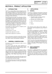
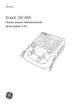
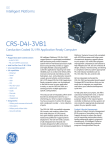
Nov 29th na vasthunnnau Integrator User’s Guide PicoTCA Shelf 9911.803 Copyright 2007 by Rittal Electronic Systems. All rights reserved. No part of this manual, including the products and/or software described in it, may be reproduced, transmitted, transcribed, stored in any retrieval system, or translated in any language, in any form, or by any means—excluding documentation that is kept by the purchaser for backup purposes—without the express written permission of Rittal Electronic Systems. Every effort has been made to ensure all information contained herein is accurate at the time of printing and is subject to change without notice and should not be construed as a commitment on the part of Rittal Electronic Systems. Neither Rittal Electronic Systems, its employees, directors, officers, or nor it’s agents are responsible for any damages, direct or consequential, to any and all equipment as a result of use of this product in a configured system. All warranties expressed or implied are void if the product has (a) been repaired, damaged, modified, or altered in any way, unless such repair, modification or alterations are authorized in writing by Rittal Electronic Systems; or (b) the serial number of the product is defaced or missing. Products and corporate names appearing in this manual may or may not be registered trademarks or copyrights of their respective companies, and are used only for identification or explanation. PICMG®, CompactPCI®, MTCA® and AMC® logos are registered trademarks of the PCI Industrial Computer Manufacturer’s Group. Any changes or modifications to this product not expressly approved by the manufacturer could void any assurances of safety or performance. ii Typographical Conventions Used in This Document Items Convention You will see the following icons periodically throughout this manual: The WARNING icon cautions you against an action or treatment that could threaten the responsiveness of the equipment or the integrity of your current work. The Note icon notifies you of the information that makes a procedure easier or clarifies an earlier description. Headings, titles, sections or words of importance. These items appear in bold typeface. Example: Any changes or modifications……….. Variable placeholders, references to other documents, new or special terminology, and emphasis. These items appear in italic typeface. Example: Table 3-1, displays….. References to chapters and sections of documents, and citations of messages displayed to users. These items appear in “quotation marks.” Example: For more information, refer to “Connections”, section 3… iii Document’s History Version Date Description Author Rev 1.0 19.08.2008 Initial Version N.J.Jujagiri iv Table of Contents Section One 1 1.0 Introduction .........................................................................................................................1 1.1 Rittal Electronic Systems, Friedhelm LOH Group ............................................................... 1 1.2 Background Information ...................................................................................................... 1 1.3 Applicability.......................................................................................................................... 2 1.4 Documentation .................................................................................................................... 2 Section Two 3 2.0 Statement on Environmental Protection ............................................................................3 2.1 Compliance to RoHS Directive............................................................................................ 3 2.2 Compliance to WEEE Directive........................................................................................... 3 2.3 Compliance to CE Directive ................................................................................................ 4 2.4 Product Safety ..................................................................................................................... 4 Section Three 5 3.0 Features ...............................................................................................................................5 3.1 Shelf Components ............................................................................................................... 5 3.1.1 Chassis ...................................................................................................................... 6 3.1.2 Backplane .................................................................................................................. 7 3.1.3 Power Supply Unit ..................................................................................................... 7 3.1.4 Power Management Board (PMB) ............................................................................. 7 3.1.5 Cooling Units (CUs) ................................................................................................. 11 3.2 Inspecting the Shelf Components ..................................................................................... 11 3.3 Guarding Against Electromagnetic Interference ............................................................... 11 3.4 Preparing the Shelf............................................................................................................ 12 3.4.1 Mounting the Shelf ................................................................................................... 12 3.4.2 Powering the Shelf................................................................................................... 13 3.4.3 Installing Boards ...................................................................................................... 14 3.4.4 Installing Filler Boards.............................................................................................. 16 Section Four 17 4.0 Maintaining the Shelf.........................................................................................................17 4.1 Maintaining the Air Filter.................................................................................................... 17 4.1.1 Cleaning the Filter.................................................................................................... 17 4.1.2 Storing Filters ........................................................................................................... 17 4.2 Replacing the Air Filter ...................................................................................................... 18 4.3 Replacing the Fan Trays ................................................................................................... 19 4.3.1 Removing a Fan Tray .............................................................................................. 19 4.3.2 Installing a Fan Tray ................................................................................................ 19 4.4 Replacing the AC Power Supply ....................................................................................... 20 4.5 Installing the Power Management Board .......................................................................... 21 4.6 Hot Swapping or Installing and Removing the MCH ......................................................... 22 Section Five 23 5.0 Functional Description ......................................................................................................23 5.1 System Backplane............................................................................................................. 23 5.1.1 Backplane Configuration.......................................................................................... 24 5.1.2 Backplane Schematics............................................................................................. 24 5.2 Fan Tray Functionality ....................................................................................................... 25 v 5.3 System Module Options .................................................................................................... 25 5.3.1 MCH Management................................................................................................... 25 5.3.2 AMC Boards............................................................................................................. 25 Section Six 26 6.0 Connectors ........................................................................................................................26 6.1 Communication line connectors ........................................................................................ 26 6.2 Backplane Connector(s) .................................................................................................... 27 6.3 JTAG Connector................................................................................................................ 27 Section Seven 28 7.0 Specifications ....................................................................................................................28 7.1 Shelf Environmental Specifications ................................................................................... 28 7.2 Shelf Physical Specifications............................................................................................. 28 7.3 Fan Tray Specifications ..................................................................................................... 28 Section Eight 29 8.0 Appendix............................................................................................................................29 8.1 Acronyms........................................................................................................................... 29 8.2 Torque Values ................................................................................................................... 31 8.3 Accessories ....................................................................................................................... 31 vi List of Figures Figure 3-1: Shelf Components .....................................................................................................5 Figure 3-2: PicoTCA Chassis.......................................................................................................6 Figure 3-3: Power Management Board (PMB) Module .................................................................8 Figure 3-4: PMB Block Diagram...................................................................................................9 Figure 3-5: PMB Assembly Drawing ..........................................................................................10 Figure 3-6: Shelf Mounting Brackets ..........................................................................................12 Figure 3-7: AC Inlet and AC Switch............................................................................................13 Figure 3-8: Removal of Mains Fuse ...........................................................................................14 Figure 3-9: AMC Board Types ...................................................................................................15 Figure 3-10: Physical/Logical Slot Locations ..............................................................................15 Figure 3-11: Front ESD Jack .....................................................................................................15 Figure 3-12: Filler Board ............................................................................................................16 Figure 4-1: Air Filter...................................................................................................................18 Figure 4-2: Fan Tray Replacement ............................................................................................19 Figure 4-3: AC Power Supply Replacement ...............................................................................20 Figure 4-4: Replacing the Power Management Board ................................................................21 Figure 4-5: Replacing the MCH..................................................................................................22 Figure 5-1: Backplane Block Diagram ........................................................................................23 Figure 5-2: Backplane Configuration ..........................................................................................24 Figure 5-3: Backplane rear side .................................................................................................24 Figure 5-4: Backplane Front side ...............................................................................................25 Figure 6-1: Section of Backplane Connector ..............................................................................27 List of Tables Table 3-1: PMB Technical Data ...................................................................................................8 Table 3-2: Pin Assignment of the Front – panel connector Telco Alarm ......................................11 Table 3-3: Country specific power cables...................................................................................14 Table 6-1: Connector P1............................................................................................................26 Table 8-1: Recommended Torque Values for the PicoTCA Shelf ...............................................31 Table 8-2: Accessories of the PicoTCA Shelf .............................................................................31 vii PicoTCA Shelf Integrator User’s Guide Section One 1.0 Introduction This section provides a brief overview about Rittal Electronic Systems. This section describes the following: • Rittal Electronic Systems • Contact Information • Background Information • Applicability • Documentation 1.1 Rittal Electronic Systems, Friedhelm LOH Group Reliable solutions depend on expertise in every detail, be it standard or customized. As one of the leading suppliers in the systems sector, Rittal Electronic Systems meets every requirement in the field of electronic packaging – from the integration of innovative components, through to complete plug and play solutions. For telecommunications, industrial automation, medical, transport and security technology. The result is always the same: a performance which meets market-specific and standardrelated requirements as well as individual customer requests. Rittal Electronic Systems ensures the required customer proximity worldwide – in every area, from consultancy through to distribution. This is achieved thanks to a global network of production sites, centers of excellence and agencies, coupled with a quality management system which ensures high standards of service and uniform product quality throughout all the world’s markets. Getting customer satisfaction also means driving developments forward in the systems sector. Rittal Electronic Systems plays an active role in the principle standardization bodies. The resultant expertise is channeled directly into our product development. In this way, Rittal Electronic Systems is continuously optimizing its range of services to secure you an unbeatable competitive edge. 1.2 Background Information When designing MicroTCA systems, use the following documents for reference: • MTCA.0 R1.0 Micro Telecommunications Computing Architecture (MTCA) • AMC.0 R2.0 Base Advanced Mezzanine Card (AMC) • AMC.1 R1.0 PCI-E Mapping • AMC.2 R1.0 Ethernet Mapping • AMC.3 R1.0 Storage Mapping • AMC.4 SRIO Mapping (Under development) 1 9911803 PicoTCA Shelf Integrator User’s Guide 1.3 Applicability This User’s Guide is applicable to the following shelf: Part Number 9911.803 Description PicoTCA 2U, 19”, 12 AMC 1.4 Documentation For more information on the system components, refer to the following documents: • AC Power Supply Data Sheet 2 PicoTCA Shelf Integrator User’s Guide Section Two 2.0 Statement on Environmental Protection 2.1 Compliance to RoHS Directive Directive 2002/95/EC of the European Commission on the "Restriction of the use of certain Hazardous Substances in Electrical and Electronic Equipment" (RoHS) predicts that all electrical and electronic equipment being put on the European market after June 30th, 2006 must contain lead, mercury, hexavalent chromium, polybrominated biphenyls (PBB) and polybrominated diphenyl ethers (PBDE) and cadmium in maximum concentration values of 0.1% respective 0.01% by weight in homogenous materials only. As these hazardous substances are currently used with semiconductors, plastics (i.e. semiconductor packages, connectors) and soldering tin any hardware product is affected by the RoHS directive if it does not belong to one of the groups of products exempted from the RoHS directive. Although many of hardware products of Rittal are exempted from the RoHS directive it is a declared policy of Rittal to provide all products fully compliant to the RoHS directive as soon as possible. For this purpose since January 31st, 2005 Rittal is requesting RoHS compliant deliveries from its suppliers. Special attention and care has been payed to the production cycle, so that wherever and whenever possible RoHS components are used with Rittal hardware products already. 2.2 Compliance to WEEE Directive Directive 2002/95/EC of the European Commission on "Waste Electrical and Electronic Equipment" (WEEE) predicts that every manufacturer of electrical and electronic equipment which is put on the European market has to contribute to the reuse, recycling and other forms of recovery of such waste so as to reduce disposal. Moreover this directive refers to the Directive 2002/95/EC of the European Commission on the "Restriction of the use of certain Hazardous Substances in Electrical and Electronic Equipment" (RoHS). Having its main focus on private persons and households using such electrical and electronic equipment the directive also affects business-to-business relationships. The directive is quite restrictive on how such waste of private persons and households has to be handled by the supplier/manufacturer, however, it allows a greater flexibility in business-to-business relationships. This pays tribute to the fact with industrial use electrical and electronical products are commonly integrated into larger and more complex environments or systems that cannot easily be split up again when it comes to their disposal at the end of their life cycles. As Rittal products are solely sold to industrial customers, by special arrangement at time of purchase the customer agreed to take the responsibility for a WEEE compliant disposal of the used Rittal product. Moreover, all Rittal products are marked according to the directive with a crossed out bin to indicate that these products within the European Community must not be disposed with regular waste. 3 PicoTCA Shelf Integrator User’s Guide If you have any questions on the policy of Rittal regarding the Directive 2002/95/EC of the European Commission on the "Restriction of the use of certain Hazardous Substances in Electrical and Electronic Equipment" (RoHS) or the Directive 2002/95/EC of the European Commission on "Waste Electrical and Electronic Equipment" (WEEE) please contact Rittal by phone or e-mail. 2.3 Compliance to CE Directive Compliance to the CE directive is declared. A ‘CE’ sign can be found on the Chassis. 2.4 Product Safety The board complies to EN60950 and UL1950. 4 PicoTCA Shelf Integrator User’s Guide Section Three 3.0 Features The PicoTCA designed and manufactured by Rittal Electronic Systems as part of its standard MicroTCA product offering. The shelf accepts up to 12 AMCs in full-size/ compact form factor, and an MCH in full-size. As an option AMC in “double full-size” is also supported. This section provides set up information and operation of the shelf: • • • • Shelf Components Inspecting the Shelf Components Guarding Against Electromagnetic Interference (EMI) Preparing the Shelf 3.1 Shelf Components The PicoTCA shelf comes equipped with the following components: • • • • • • 1 rack-mounted system 482.6 mm (19”), 2U, 250 mm deep 2 fan tray modules 1 air filter 1 power management board 1 power supply unit 1 backplane, 13 slots Refer to figure 3-1 for the location of component on the shelf. Figure 3-1: illustrates the location of the shelf components. PicoTCA Shelf Front view Backplane Air Filter Fan tray Mounting brackets Power Management Board ESD Jack PicoTCA Shelf Rear view AC inlet and switch AC Power Supply Figure 3-1: Shelf Components 5 PicoTCA Shelf Integrator User’s Guide 3.1.1 Chassis • Scalable and reconfigurable with up to 12 plug-in AMC modules • Single MTCA Carrier Hub (MCH) • Power Management Board for 12 AMC modules, 1 MCH and 2 CUs • Integrated AC Power supply module up to 450 W for payload power - 90 – 264 V AC 47 – 63 Hz with PFC • 2U 19” chassis usable in 300 mm deep telecom racks - System Dimensions without connectors - H x W x D: 87 mm x 482.60 mm x 250.00 mm (2U x 19.00” x 10”) - Approximate weight with backplane and power supply – 5.9 kg • Reliable cooling mechanism for AMC modules 20 W to 60 W power dissipation - 40 W for installed MCH modules • Up to 40 GB/s data rate on the backplane • System Mounting - Use standalone or mounted in a 19-inch rack • Includes 2 hot-swappable cooling units • Exchangeable air filter Figure 3-2: illustrates the PicoTCA Chassis Figure 3-2: PicoTCA Chassis 6 PicoTCA Shelf Integrator User’s Guide 3.1.2 Backplane • Backplane support • 1 x Gigabit Ethernet on port 0 • 2 x SATA/SAS on ports 2 & 3 • 4 x PCI Express on ports 4, 5, 6 & 7 • MTCA backplane supports AMC.0 …AMC.4 modules • JTAG connector for debug and test • AMC connectors based on con:card+ design • Processor AMC communicates with adjacent SAS/SATA module via point-to-point connection 3.1.3 Power Supply Unit The AC input to the power unit accepts any voltage between 90 V and 264 V of alternating current. The integrated power subsystem provides up to 450 W of power to the various boards and other electrical devices. Power is supplied in two categories: management power and payload power. • • • • • • • • • AC Input Voltage: 90 – 264 VAC Input Frequency: 47 – 63 Hz Power Factor per EN61000-3-2: > 0.95 W/VA Hold-up time at 115 VAC (after last line peak, full-rated load): 20 ms Input current at 90 VAC (full-rated load): 6 A rms o Inrush Surge current at 264 VAC at 25 C (Excluding Xcap): 15 Apk o Over temperature shut down: 62 +/- 3 C Over current/ Short-Circuit protection (Latching Mode) 12 V: 38.4 to 47.6 A 3.3 V: 3.2 to 6A Over voltage protection (Latch Style) 12 V: 15 V 3.3 V: 4.3 V 3.1.4 Power Management Board (PMB) The power management board is in a separate slot in the PicoTCA chassis. PMB compromises the following functionalities. • Power Management • Cooling Management • Telco Alarm (Optional) It enables a central management instance like a MCH to individually control the management and payload power supply the AMC slots and fan units. The cooling unit module provides control and supervisory functionality for two fan bays. The cooling units monitors several temperature sensors within the chassis. The implemented Telco Alarm unit provides telco alarm functionality as specified by the MTCA specification [1]. Input voltage is from the integrated power supply. Output is to 15 independent channels of 12 V for payload power and 3.3 V for management power. • Management and payload power for 12 AMCs, 1 MCH and 2 CUs • EMMC with IPMB to facilitate communication with the Carrier Manager • Status LEDs 7 PicoTCA Shelf Integrator User’s Guide Figure 3-3: illustrates the PMB Module. Figure 3-3: Power Management Board (PMB) Module Board Specification Payload Power Input: Management Power Input: Power Drive Capability: Payload Power Management Power Payload Power Over current Protection: PMB Power Consumption: (without any connected units) 8V-14V DC, 36,6 A 3.4V +-5%, 3A 8 A max 150 mA max 10A Fuse 3.3V 300mA max. Table 3-1 : PMB Technical Data PMB Features CPU and Memory: Dual ATMega 16 CPU with onboard 16 KByte Flash Power Management: The PMB power module supports Power Management for • • • 12 AMCs, 2 cooling units 1 MCH Cooling Management: The onboard cooling provides support for: • • • Up to two fan bays One local and up to seven temperature sensors on the backplane Two tacho sensors Telco Alarm: The Pico PMB supports as an assembly option the Telco Alarm functionality. External Connectors and Buttons: • A MTCA compliant DB15 Connector for external Telco Alarm actors is available on the faceplate • One push button to reset Telco Alarm conditions 8 PicoTCA Shelf Integrator User’s Guide LEDs: LED indicators on the faceplate are available for the following functions: 1. Payload power good indicator 2. Management power good indicator 3. Telco Alarm Indicators for minor, major and critical alarm (Telco option only) Face Plate Backplane IPMB-0A IPMB-0B External Alarm Control Cooling Unit CPU ATMega16 Power Module CPU ATMega16 Registers D8 Major Alarm Minor Alarm Payload Power Management Power Alarm Reset Critical Alarm Analogue Power Circuitry Telco Alarm -optional- Drivers/ Latches PP Good #PS1, PWR_ON #EN MP Good PWM Fan Bays Tacho Temperature Sensors Onboard Temperature Sensor PicoPM – Block Diagram Figure 3-4: Power Management Board (PMB) Block Diagram Operation: Power Management: The power management part of the PMB manages the payload and management power of any connected AMC and Cooling unit. After power up the power module starts in autonomous mode and supplies payload power to the cooling units and the MCHs. As soon as the MCH has taken over control of the power module, the power module changes to normal mode and reacts to power commands from the MCH. Cooling Management: The main purpose of the Cooling Unit is the controlling and monitoring of the attached fan units. PMB considering the two fan trays in PicoTCA chassis as one cooling unit. The other functionality of the Cooling management unit of the PMB is reading the temperature locally on the PMB and additional temperature sensors on the backplane. It supports up to eight temperature sensors connected to the “one wire bus”. Telco Alarm – Assembly Option: The onboard Telco Alarm module provides the telco alarm functionality as defined by the PICMG 3.0 Revision 2.0 ATCA specification. The telco alarm system consists of a distinct 9 PicoTCA Shelf Integrator User’s Guide dry contact relay that corresponds to each alarm state. Besides that for each alarm state a distinct LED indicator is available. Alarm states can be resetted by a front panel push button switch . Connectors and Indicators at the Face Plate Figure 3-5: PMB Assembly Drawing Power Status Indicators: Led Green – PP Good: Payload Power good indicator Led Green – MP Good: Management Power good indicator Operation: Solid green – power is in range Flashing - power is not ok Telco Alarm Indicators: Led Red – Critical Alarm: Led Red – Major Alarm: Led Amber – Minor Alarm: Indicates a Telco critical alarm condition Indicates a Telco major alarm condition Indicates a Telco minor alarm condition Telco Alarm Connector: monitoring MTCA compliant alarm connector for external alarm Telco Reset Button: Button to clear a Telco alarm condition Telco Alarm Connector – DB15 The following table shows the pin assignment of the signals of the Telco Alarm connector in the form of a Sub-DB15 connector. 10 PicoTCA Shelf Integrator User’s Guide Pin No. 1 2 3 4 5 6 7 8 Signal Pin No. Minor Reset + Minor Reset Major Reset + Major Reset Critical Alarm NO Critical Alarm NC Critical Alarm COM Minor Alarm NO 9 10 11 12 13 14 15 Signal Minor Alarm NC Minor Alarm COM Major Alarm NO Major Alarm NC Major Alarm COM PWR Alarm NO PWR Alarm Table 3-2 : Pin Assignment of the Front-panel Connector Telco Alarm 3.1.5 Cooling Units (CUs) • 2 fan trays with 2 fans each (push & pull) • Each tray provides up to 62 CFM (105 m³/h), air pressure 48 Pa 3.2 Inspecting the Shelf Components During the course of handling, shipping, and assembly, pins, shrouds, mounting screws, blowers and other items can become damaged and/or loose. WARNING: Before utilizing the shelf, perform a thorough inspection to ensure the shelf and its components are not damaged. Operating a damaged shelf can cause serious damage to the shelf and/or the devices that interface to it. To inspect the shelf: 1. Visually inspect the shelf to ensure that all of the connector pins are straight, shrouds are properly seated, screws are tight, and so on. During inspection, it helps to know the specific products that are included with the metal enclosure of the subrack. For a listing of specific components, refer to shelf components section 3.1 on page 5. 2. Check air filter is properly installed. 3. Check the EMI gaskets for damage. 4. Repair any bent pins and shrouds, also tighten loose screws before proceeding. Carefully repair any bent pins, shrouds, loose screws, etc. before proceeding. If unsure how to proceed or if the damage to the Shelf is extensive, contact Customer Service for assistance. 3.3 Guarding Against Electromagnetic Interference The system contains gaskets at the shelf and board level to guard against electromagnetic interference (EMI). Ensure that the shelf system is grounded and that each of the shelf system’s individual components contact the gaskets (such as stainless steel springs and large surface conductive connections). 11 PicoTCA Shelf Integrator User’s Guide The shelf guide rails are also fitted with electrostatic discharge (ESD) contacts for each AMC card. These ESD contacts ensure that the boards are fully discharged to prevent electro static caused by electro static as they are plugged into the system. 3.4 Preparing the Shelf The shelf measures 87 mm high x 482.6 mm wide x 250 mm deep (2U high x 19 in. wide x 10 in. deep). Side flanges are provided to allow the shelf unit to be mounted in a 19” (482.6 mm) cabinet. In preparing the shelf system, perform the following: • • • • Mounting the Shelf Powering the Shelf Installing Boards Installing Filler Panels 3.4.1 Mounting the Shelf The PicoTCA shelf comes with integrated mounting brackets mounted (see figure 3-6 on page 12) that can be used for rack mounting. When mounting the shelf into a rack, follow the customer-defined rack mounting procedures. The mounting brackets adhere to the IEC 60297-1 and EIA 310-D Section 1 standards. When rack mounting, the bracket mounting holes will accept bolts/screws up to 6 mm (0.24 in.) diameter. Figure 3-6: illustrates the shelf rack mounting brackets. Figure 3-6: Shelf Mounting Brackets WARNING: To prevent ESD damage to the shelf and its components, it is important to follow ESD safe handling practices when mounting the shelf. 12 PicoTCA Shelf Integrator User’s Guide 3.4.2 Powering the Shelf Before inserting boards, power the shelf to ensure that it is operating properly. The power connections and the mains switch are located at the top right rear of the shelf. Follow the procedure outlined when powering the shelf for the first time. To power the shelf for the first time: 1. Ensure that the AC switch is set to the OFF position by pressing (O). 2. Connect the AC Inlet via AC cable (C13, 10 Amp, not supplied) to the 110/220 V AC feed. 3. Turn the mains switch to the ON position by pressing (I). 4. After 1-2 seconds, all the system fans will begin to operate at 100% speed. Visually check that all fans are operating. If the fans are not operating, check that the mains cable is properly inserted, the mains switch is set to the ON position (I) and that the mains AC feed is on. 5. After 4 seconds the LEDs on Management board are shining green. 6. The system fans operate at 60% speed (at 25 oC ambient) 7. If there is no MCH in the chassis the Payload power and Management power LEDs will be green and fans will run at 100% speed. Figure 3-7: illustrates the location of the AC inlet with mains fuse and AC switch. Figure 3-7: AC Inlet and AC Switch To replace mains Fuse: 1. Ensure that the mains switch is set to the OFF position by pressing (O). 2. Disconnect the AC cable from the 110/220 V AC feed. 3. Replace Fuse gently with screw drivers as show in the figure 3.8 13 PicoTCA Shelf Integrator User’s Guide Figure 3-8: illustrates removal of Mains Fuse. Figure 3-8: Removal of Mains Fuse Country specific power cables are available as Rittal standard products. Part Number Voltage Volt Country version 7200.210 230 D/F/B 7200.211 230 GB 7200.213 230 CH 7200.214 230/115 USA/CDN Table 3-3: Country specific power cables Technical specifications: PVC-cable, 3 pole, with IEC connector C19/C20 (non-heating appliances) with contact protection CEE22. 3.4.3 Installing Boards The shelf is compliant with MTCA.0 R1.0 MicroTCA and accepts boards that are compliant with MTCA.0 R1.0, AMC.0 R1.0 & R2.0 WARNING: Boards should slide easily when installing or removing them from the shelf. Should boards not slide easily, verify the alignment of the mechanicals and the backplane to prevent any damage to the backplane or the board(s). There is no preset order to inserting boards into the shelf. For more information on inserting boards, refer to the user manual(s) supplied with the board(s). 14 PicoTCA Shelf Integrator User’s Guide Figure 3-9: illustrates AMC board types MCH Full Size Compact Compact Figure 3-9: AMC board types Figure 3-10: illustrates the logical slot locator AMC_09 AMC_05 AMC_03 AMC_04 AMC_07 AMC_01 AMC_11 AMC_10 AMC_06 MCH AMC_08 AMC_02 AMC_12 Figure 3-10 Physical/Logical Slot Locations Figure 3-11 illustrates the front ESD Jack ESD Jack Figure 3-11 Front ESD Jack The figure 3-10 defines the physical/logical slot allocation. MCH shall be mounted in the slot as shown in the figure 3-10 AMC Slots are numbered 1 to 12 for the PicoTCA shelf. To install Boards: WARNING: To prevent ESD damage to the shelf and its components, it is important to follow ESD safe handling practices when installing boards into the Shelf. 1. Connect the wrist unit to the shelf by attaching it to the front lower middle ESD jack (see figure 3-11 on page 15) 2. Ensure that the handle on the board is in the open state. 3. Align the board with the left and right lead-ins and insert until the handle engages. 4. Close the handle (towards the faceplate) in the lock position. 15 PicoTCA Shelf Integrator User’s Guide 3.4.4 Installing Filler Boards The MTCA specification specifies that in a partially populated shelf, filler boards (with integrated air baffles) are mandatory to ensure consistent cooling performance across all slots within the shelf. WARNING: Boards should slide easily when installing or removing them from the shelf. Should boards not slide easily, verify the alignment of the mechanicals and the backplane to prevent any damage to the backplane or the board(s). WARNING: To prevent ESD damage to the shelf and its components, it is important to follow ESD safe handling practices when installing boards into the Shelf. To install filler board: 1. Before installing a filler board in the shelf, follow the ESD procedures. ESD shelf jack is located on the front lower middle. (see figure 3-11 on page 15) 2. Ensure that the handle on the filler board is in the open position. 3. Align the filler board(s) with the left and right lead-ins and insert until the handle engages. 4. Close the handle (towards the faceplate) in the lock position. Figure 3-12: illustrates a filler board. Figure 3-12: Filler Board 16 PicoTCA Shelf Integrator User’s Guide Section Four 4.0 Maintaining the Shelf WARNING: Only qualified trained personnel should service this equipment. Follow the proper grounding and safe power handling procedures. The following maintenance procedures may be required to keep the shelf operating efficiently: • • • • • • Maintaining the Air Filter Replacing the Air Filter Replacing the Fan Trays Replacing the AC Power Supply Replacing the Power Management Board Replacing the MCH 4.1 Maintaining the Air Filter Routine filter maintenance is required to ensure that the shelf operates efficiently. The following procedures will ensure that the filter is properly maintained: • Cleaning the Filter • Storing Filters • Replacing the Filter 4.1.1 Cleaning the Filter The shelf filter needs to be clean to ensure effective filtration and airflow. Filter maintenance frequency will depend on the environment the system is subjected to. Remove the shelf air filter (refer to replacing the air filter section 4.2 on page 18, for filter removal). There are four ways to clean the shelf filter: 1. Vacuum Clean: A few passes of a vacuum cleaner can remove accumulated dust and dirt. 2. Oil-Free Compressor Air: Point the compressed air nozzle in the opposite direction of the filter’s operating airflow (blow from the filter’s exhaust side toward the intake side). 3. Cold Water Rinse: Collected dirt is washed away using just a standard hose nozzle with plain water. Let stand till completely dry before returning to service. 4. Immersion in Warm Soapy Water: Dip the filter in a solution of warm water and mild detergent. Then rinse the filter in clear water and let stand until completely dry before returning to service. 4.1.2 Storing Filters It may be best to keep extra filters on hand to make changing the Shelf filter easier. The ideal storage condition for polyurethane foam is a cool, dry, dark environment. High temperature, humidity, and ultraviolet light adversely affect the filter media. Foam also degrades when exposed to solvents and sulfates, such as engine exhaust. 17 PicoTCA Shelf Integrator User’s Guide Controlling relative humidity between 40% - 80% and temperature between 4.4° C - 32.2° C (40° F - 90° F) yields an acceptable environment. Covering the filters with dark plastic keeps the foam dry and protects it from ultraviolet light. 4.2 Replacing the Air Filter Filter replacement frequency will depend on the environment the system is subjected to. The filter is located on the right side of the right fan tray and can be accessed from the front. Follow the procedure outlined to replace the filter in an operating shelf: 1. Refer to section 4.3.1, on page 19 for proper fan tray removal procedure. Figure 4-1: illustrates the location of the air filter. Figure 4-1: Air Filter 2. With the fan tray handle, pull the fan tray together with the filter out partially from the shelf. WARNING: Extreme care should be taken while handling the fan tray. It is recommended to pull the fan tray out partially and wait until the fan’s impellers have stopped spinning. WARNING: Operating the shelf with the fan tray removed may cause the shelf to steadily heat up and possibly start to power down. Replace the fan tray with the filter immediately after removal. 3. Loosen the air filter screw and by holding the filter frame, remove the filter from the shelf. 4. Place the new filter to the fan tray and tighten filter screw. 5. Reinstall the fan tray/air filter back into the shelf. 6. Refer to section 4.3.2, on page 19 for proper fan tray installation procedures. 18 PicoTCA Shelf Integrator User’s Guide 4.3 Replacing the Fan Trays The shelf is equipped with two fan trays. The fan trays are located on the right and left side of the shelf as viewed from the front. There is a separate procedure when removing the left and right fan trays (the right fan tray also incorporates the air filter). 4.3.1 Removing a Fan Tray The steps required for removing a fan tray are as follows: 1. Rotate the knob on the fan tray to completely anticlockwise direction. When a fan tray is taken out of operation, the MCH may compensate for the loss by increasing the speed of the remaining fan tray. WARNING: Extreme care should be taken while handling the fan tray. It is recommended to wait until the fan’s impellers have stopped spinning before removing the fan tray. 2. With the fan tray handle, pull the fan tray toward the front of the shelf and remove. The same steps are required for removing a non-functioning fan tray A non-functioning fan tray can be characterized in one of two ways. One (depending on the internal failure) is when the fan tray no longer communicates with the MCH and the fans will be either at its last programmed speed or at 100% speed. Two is when one or more of the fans no longer respond to speed commands and (depending on the internal failure) the fan is at 0 RPM speed. Figure 4-2: illustrates replacing the fan tray. Figure 4-2: Fan Tray Replacement 4.3.2 Installing a Fan Tray The steps required for installing a fan tray are as follows: 1. Insert the replacement fan tray into the shelf guide rails and ensure that the interface connectors align. 19 PicoTCA Shelf Integrator User’s Guide WARNING: Do not force the fan tray, the connector should seat easily into position. Forcing the fan tray may cause damage to the interface connector pins. 2. Rotate the knob on the fan tray in the clockwise direction until it is fully tight. 3. The MCH will communicate with the fan tray. The fan tray is now under control of the MCH. When replacing the right side fan tray integrated with the air filter, refer to section 4.2 on page 18, for additional installation procedures. 4. Query the MCH to ensure the fan tray is operating properly. Refer to the MCH manual for additional information. 4.4 Replacing the AC Power Supply The shelf is equipped with one AC power supply. The power supply is located at the rear of the shelf. For more information on the power supply, refer to the AC power supply instruction manual. The steps required for removing and inserting the power supply are as follows: 1. Disconnect AC power to the shelf and ensure that the AC switch is set to the OFF position by pressing (O). Figure 4-3: illustrates replacing the AC power supply. AC inlet and switch Power supply Face plate mounting screws mounting screws Power supply mounting screws Figure 4-3: AC Power Supply Replacement 2. Loosen the four thumbscrews on the power supply mounting plate and carefully pull the power supply away from the shelf. 3. Disconnect faston connectors from the main inlet socket. 20 PicoTCA Shelf Integrator User’s Guide 4. Unscrew the earth contact to the rear panel. 5. Unplug the PCB connector. 6. Remove the four faceplate mounting screws and the faceplate from the power supply (set aside). 7. Reinstall the faceplate to the new power supply with four screws and torque to 0.6Nm (5.3lbf.in). 8. Reconnect the PCB connector to the new power supply 9. Ground wiring. 10. Put on the faston connectors in the main input. 11. Install the power supply to the shelf with the four thumbscrews on the power supply mounting plate. 12. Reconnect power to the shelf and set the AC switch to the ON position by pressing (I). 13. The fans will begin to operate after 2-5 seconds to indicate that the power supply is operational. 4.5 Installing the Power Management Board The power management board is a custom size board. Follow the procedure outlined when installing or removing the PMB. To install the PMB: 1. Ensure that the AC switch is set to the OFF position by pressing (O). 2. Connect the wrist unit to the shelf by attaching it to the ESD jack. 3. Slide the Board into the slot. 4. Tighten the retaining screw. Figure 4-4: illustrates replacing the Power Management board. Figure 4-4: Replacing the Power Management Board 21 PicoTCA Shelf Integrator User’s Guide To remove the PMB: 1. Ensure that the AC switch is set to the OFF position by pressing (O). 2. Connect the wrist unit to the shelf by attaching it to the ESD jack. 3. Relax the retaining screw. 4. Slide the Board out of the slot. WARNING: Boards should slide easily when installing or removing them from the shelf. Should boards not slide easily, verify the alignment of the mechanicals and the backplane to prevent any damage to the backplane or the board(s). 4.6 Hot Swapping or Installing and Removing the MCH The MCH should be complaint with MTCA.0 and AMC.0. WARNING: Boards should slide easily when installing or removing them from the shelf. Should boards not slide easily, verify the alignment of the mechanicals and the backplane to prevent any damage to the backplane or the board(s). The figure 3-10 identifies the physical/logical slot allocation. MCH should be mounted in the slot 0 as shown in the figure 3-10. WARNING: To prevent ESD damage to the shelf and its components, it is important to follow ESD safe handling practices when installing boards into the Shelf. To install Boards: 1. Connect the wrist unit to the shelf by attaching it to the front lower middle ESD jack (see figure 3-11 on page 15) 2. For hot swapping, inserting or removal MCH, refer to the user manual supplied with MCH. Figure 4-5: illustrates replacing the MCH. Figure 4-5: Replacing the MCH 22 PicoTCA Shelf Integrator User’s Guide Section Five 5.0 Functional Description This section describes the primary operational functionality of the PicoTCA chassis. 5.1 System Backplane The PicoTCA system backplane is a key part of the PicoTCA system that allows for highbandwidth, low-latency communications between system modules. The following is a high-level block diagram of the backplane and system architecture: Figure 5-1:Backplane Block Diagram (example of a prevalidated configuration) Figure 5-1 Backplane Block Diagram The platform provides Common Option (CO) and Fat Pipe (FP) region connectivity to each installed AMC. These are non-blocking Gigabit Ethernet channels to Port 0 of each AMC slot that are provided by the MCH for CO connectivity. External access to the CO interconnect is available via a RJ-45 connector on theMCH front panel. X4 PCI Express FP connections to each AMC slot are supported. Point-to-point backplane connections between AMC slot ports 2 and 3 provide support for SATA or SAS AMCs in the system. 23 PicoTCA Shelf Integrator User’s Guide 5.1.1 Backplane Configuration Figure 5-2: illustrates Backplane configuration Figure 5-2: Backplane configuration 5.1.2 Backplane Schematics Figure 5-3: illustrates Backplane rear side Figure 5-3: Backplane rear side 24 PicoTCA Shelf Integrator User’s Guide Figure 5-4: illustrates Backplane front side JTAG P1 Figure 5-4: Backplane front side 5.2 Fan Tray Functionality The EMMC enabled fan tray responds to all mandatory and fan tray specific commands as defined in MTCA.0 R1.0. On power-up, the EMMC defaults the fan tray speed to 100%. The MCH is responsible for all subsequent speed adjustments. Should the EMMC fail, the fan tray will automatically default to 100% speed. There is no closed-loop control present in the fan tray. All speed changes must be initiated by the MCH. 5.3 System Module Options 5.3.1 MCH Management MTCA specified IPMI management, networking, and clock infrastructure are supplied by the MCH. The power subsystem provides power conversion, management, and distribution. Both the MCH and power subsystem provide support for hot insertion and extraction of AMC cards. Direct serial console access to the embedded management firmware is enabled via a front-panel connector on the MCH. A convenient Command Line Interface (CLI) provides easy access and control of the firmware. The IPMI-based management architecture provides all hardware management support. The MTCA Carrier Management Controller (MCMC), located on the MCH, provides the primary management function. Radial IPMB-L connections are routed from the MCH to individual AMC slots. Dual Redundant IPMB-0 buses are routed from the MCH to the power subsystem and CUs. For more information please refer MCH Manual. 5.3.2 AMC Boards PicoTCA Chassis is compatible to all AMC cards available in the market. Tests were conducted with AMC cards from GeFanuc like Telum ASLP 10, Telum 200-SATA, Telum 2001-VGA, Telum GE-QT etc. 25 PicoTCA Shelf Integrator User’s Guide Section Six 6.0 Connectors 6.1 Communication line connectors Table 6-1: displays the Connector P1 PIN 1 2 3 4 5 6 7 8 9 10 11 12 JTAG_Z GND GND GND GND GND GND GND GND GND GND GND JTAG_A TCK_M1 TCK_PM1 GND TDO_A01 TDI_A01 GND TDO_A03 TDI_A03 GND TDO_A05 TDI_A05 JTAG_B TMS_M1 TMS_PM1 TRST_A01 TMS_A01 TCK_A01 TRST_A03 TMS_A03 TCK_A03 TRST_A05 TMS_A05 TCK_A05 JTAG_C TRST#_M1 TRST_PM1 GND GND MPOW_M1 MPOW_M1 GND SLA * GND PPOW_M1 JTAG_D TDO_M1 TDM_PM1 TMREQ_M1 TDO_A02 TDI_A02 GND TDO_A04 TDI_A04 GND TDO_A06 TDI_A06 JTAG_E JTAG_F TDI_M1 GND TDI_PM1 GND TRST_A02 GND TMS_A02 GND TCK_A02 GND TRST_A04 GND TMS_A04 GND TCK_A04 GND TRST_A06 GND TMS_A06 GND TCK_A06 GND GND TDO_A08 TDI_A08 GND TDO_A08 TRST_A08 TMS_A08 TCK_A08 TRST_A10 TMS_A10 GND GND GND GND GND TCK_A10 TRST_A12 TMS_A12 TCK_A12 TDI_PM2 TDI_M2 GND GND GND GND GND GND KEY 13 14 15 16 17 18 19 GND GND GND GND GND GND TDO_A07 TDI_A07 GND TDO_A09 TRST_A07 TMS_A07 TCK_A07 TRST_A09 TMS_A09 PPOW_M2 GND SLC * GND MPOW_M2 20 21 22 23 24 25 GND GND GND GND GND GND TDI_A09 GND TDO_A11 TDI_A11 TCK_PM2 TCK_M2 TCK_A09 TRST_A11 TMS_A11 TCK_A11 TMS_PM2 TMS_M2 MPOW_M2 GND TDI_A08 TMREQ_M2 TDO_A12 GND TDI_A12 TRST#_PM2 TDO_PM2 TRST#_M2 TDO_M2 Table 6-1: Connector P1 *) SDA and SLC is the I2C bus MCH tongue I PIN 129 and 130 from MCH to EPROM PIN 5 and 6 26 PicoTCA Shelf Integrator User’s Guide 6.2 Backplane Connector(s) Figure 6-1: illustrates the backplane connector. Figure 6-1: Section of Backplane Connector 6.3 JTAG Connector A JTAG Switch Module (JSM) connector on the backplane enables a JSM that provides a mechanism for system-level test based on the JTAG architecture in a star topology. A JSM model supporting this platform is planned. 27 PicoTCA Shelf Integrator User’s Guide Section Seven 7.0 Specifications 7.1 Shelf Environmental Specifications Temperature: Operating Storage Transport 0° C to 45° C -40° C to 85° C -40° C to 85° C Humidity: Operating Storage Transport 5% to 90% non-condensing 5% to 90% non-condensing 5% to 90% non condensing Shock & Vibration IEC 61587-1, DL1 Altitude: -60 m to +1800 m ASL (NEBS Level 3, GR-63-CORE) Regulatory Compliance: EN60950-1/ UL 60950 LVD 2006/95/EG EN 55022 Class A FCC Part 15, Class A EN 55024 EN 61000-3-2/ EN61000-3-3 7.2 Shelf Physical Specifications Weight : 5.9 Kg Height: 87 mm (2U) Width: 482.6 mm (19 in.) Depth: 250 mm (10 in.) Rack Mounting: 19” (482.6 mm) Max. Single Full-size Module Weight: 0.35 Kg (0.77 lb) 7.3 Fan Tray Specifications 3 Air Flow: 105 m /h (62 CFM) per fan tray of 2 fans Static Pressure: 48 Pa per fan tray Noise: Full speed, 38 db(A) per fan tray MTBF: Full speed, 70,000 hr. at 40° C Full speed, 35,000 hr. at Tmax Nominal Voltage : Voltage Range: • 12 VDC 10.8 VDC to 13.2 VDC Shelf weight includes one AC power supply, one backplane, one filter, one PMB and two fan trays. 28 PicoTCA Shelf Integrator User’s Guide Section Eight 8.0 Appendix 8.1 Acronyms The following list will provide definitions of acronyms used throughout this document. ACRONYM ASL AMC ATCA BT Backplane CFM CM CompactPCI CPU CU ECN EIA EMI EMMC ESD FRU FRU Info Hot Swap HPI H/S IEC I/O IPMI IPMB IPMB-0 IPMB-A, IPMB-B IPMB-L I²C IPMC DEFINITION Above Sea Level Advanced Mezzanine Card Advanced Telecom Computing Architecture Block Transfer An interconnecting device with connectors, allowing Modules to plug into it Cubic Feet per Minute Carrier Manager Compact Peripheral Component Interconnect Central Processing Unit Cooling Unit, Fan Engineering Change Notice Electronic Industries Alliance Electromagnetic Interference Enhanced Module Management Controller, used on Cooling Units, Power Modules, and OEM Modules Electrostatic Discharge Field Replaceable Unit – Any entity that can be replaced by a user in the field Information stored in a nonvolatile memory on a device To remove a component (e.g., an AMC module) from a system (e.g., a MicroTCA Shelf) and plug in a new one while the power is still on and the system is still operating Hardware Platform Interface, SW management interface defined by SAF Hot Swap International Electro technical Commission Input / Output Intelligent Platform Management Interface – Specification detailing the hardware and software interfaces required for system management Intelligent Platform Management Bus – Two wire serial bus specified in IPMI used to transmit management information. A dual redundant IPMB that connects MCMCs and EMMCs in a MicroTCA Carrier. Electrically and logically separate from the Local IPMB (IPMB-L) Intelligent Platform Management Buses A and B, respectively,. Refers to the two redundant IPMBs that aggregate into IPMB-0 Connects AMC’s MMC with the MCH’s MCMC. Electrically and logically separate from the MCMC’s IPMB-0 Inter-integrated Circuit bus, a multi-master, two wire serial bus used as the basis for IPMBs IPM Controller, e.g. MCH CPU 29 PicoTCA Shelf Integrator User’s Guide JTAG Switch Module (JSM) KCS LAN LED ID LUN LVDS MCMC MicroTCA Carrier Hub (MCH) MMC MTBF MTCA MTCM NetFn OEM Module Open HPI PCB PCI PEF PICMG PM POH PU PWR RCS RMCP RPT SAF SDR SEL SM SMI SMIC SMS SNMP SSID SSOID SW TCA U UDP A Module that controls the distribution of JTAG signaling to the AMCs and MCHs within a MicroTCA Carrier Keyboard Controller Style Local Area Network Light Emitting Diode Identifier Logical Unit Number Low Voltage Differential Signal MicroTCA Carrier Management Controller, management controller on MCH. The required management controller that interfaces to AMC MMCs via IPMB-L and to CU, PM, and OEM module EMMCs via IPMB-0 An assembly providing MicroTCA Carrier functions needed to support up to 12 AMCs including MCMC, optional ShMC, optional fabric switch, and clock The required management controller on an AMC module which interfaces to the MicroTCA Carrier Manager on the MCH via IPMB-L Mean Time Between Failures Micro Telecommunications Computing Architecture MTCA Carrier Manager Network Function, functional class of message A Module proprietary to a specific Original Equipment Manufacturer, managed over IPMB-0 Specific HPI implementation, http://www.openhpi.org/ Printed Circuit Board Peripheral Component Interconnect Platform Event Filtering PCI Industrial Computer Manufacturers Group Power Module (=PU) Power On Hours Power Unit (=PM) Power Remote Console Software, SW running on a remote system Remote Management Control Protocol, UDP based, IPMI over LAN Resource Presence Table, data base of logical resources Service Availability Forum, http://www.saforum.org/ Sensor Data Record, sensor description System Event Log Shelf Manager System Management Interrupt Server Management Interface Chip, type of interface to an IPMI BMC System Management Software, SW running on BMC Simple Network Management Protocol System Software Identifier System Sensor Owner Identifier Software Telecom computing Architecture Unit (vertical height) User Datagram Protocol 30 PicoTCA Shelf Integrator User’s Guide 8.2 Torque Values Table 8-1: displays the recommended torque values for fasteners used on the PicoTCA Shelf. Screws Torque M3 0.6 Nm (5.3 lbf.in) M4 2.5 Nm (22 lbf.in) M6 7.12 Nm (63 lbf.in) Table 8-1: Recommended Torque Values for the PicoTCA Shelf 8.3 Accessories Table 8-2: displays the accessories of the PicoTCA Shelf. Part Number Description 9910.104 9909.923 9906.621 3666.000 9911.570 Ri-MCH-base12-GbE Ri-MCH-base12-GbE-SSC-x24 Ri-MCH-base12-GbE-SSC-x48 Ri-MCH-base12-GbE-TC-SRIO x48 9911.891 Air baffle plate compact 9911.893 9911.885 Air baffle plate full-size AMC face plate kit single x compact 9911.886 AMC face plate kit single x full-size AMC filler sheet single Table 8-2: Accessories of the PicoTCA Shelf 31 PicoTCA Shelf Integrator User’s Guide Issue: 1.0 08/2008 Doc-No.: P0249900RV74 32