1
CONNECTORS : SIGNALS AND PINOUTS
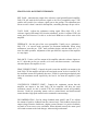
Motor and power connections are made via a four terminal screw connector ( P2 ).
Signal connections are made via a 15 pin 0.1” pitch connector ( P1 ).
4 PIN POWER CONNECTOR P2
PIN 1 : MOTOR OUT +, positive output
PIN 2 : MOTOR OUT -, negative output
PIN 3 : + HV RETURN (GND)and chassis ground
PIN 4 : +HV, the high voltage DC power input.
15 PIN SIGNAL CONNECTOR P1
PIN 1: +12V OUT, 10 mA MAX.
PIN 2 : ENABLE-, ACTIVE LOW CMOS INPUT.
PIN 3 : NEG ENABLE-, ACTIVE LOW CMOS INPUT.
PIN 4 : POS ENABLE-, ACTIVE LOW CMOS INPUT.
PIN 5 : RESET-, ACTIVE LOW CMOS INPUT.
PIN 6 : NORMAL / FAULT OPEN COLLECTOR OUTPUT.
PIN 7 : OVERCURRENT CMOS OUTPUT.
PIN 8 : CURRENT MONITOR OUTPUT.
PIN 9 : AUX INPUT.
PIN 10 : SIGNAL GROUND.
PIN 11 : -REF IN ( DIFFERENTIAL INPUT ).
PIN 12 : + REF IN ( DIFFERENTIAL INPUT ).
PIN 13 : SIGNAL GROUND.
PIN 14 : TACH INPUT.
PIN 15 : -12V OUT, 10 mA MAX.
GETTING STARTED
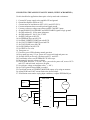
To install the amplifier you will require a control, or reference, voltage, a power
supply, and a load. The reference voltage can be as simple as a potentiometer, or as
complex as a digital control system. First you must determine the mode of operation,
and the connect the amplifier to power supply, load and control system. Once
installed, you will next power up and check that the motor, tachometer and control
signal polarities are correct. The final operation is tuning, the process of adjusting
amplifier gain, control system parameters, etc. to achieve the desired performance of
the system.
OPERATING MODES
A mode is simply the way that the amplifier is used. Because the amplifier is one of
the several components comprising a system, the operating mode frequently depends
on the other components in the system. A tachometer is the most important option in
determining the operating mode. If you use a tachometer, the amplifier will be