1
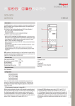
MyHOME
automation
F422
The use of the interface with this mode may be useful to keep the Automation system
and the Temperature control system separate (for example when using independent
power supplies).
Automation
OUT
OUT
C
IN
I1
I2
I3
I4
MOD
=
=
=
=
=
–
–
–
1
6
IN
Energy management
Installation rules:
- Each individual system connected to the IN or OUT clamps of the interface must be
powered by its own power supply.
- It is possible to use up to 4 interfaces in MOD=6 for the connection of the Automation and/
or Energy Management, and Temperature Control systems to each other.
- In case of cascade connection of several Automation and/or Energy management, and
Temperature Control systems, each individual system must be connected to the OUT clamp
of one interface and the IN clamp of the other. Therefore, do no connect the system to the
two interfaces only using the OUT clamps.
- Do not configure positions l1 and l2.
- In positions l3 and l4, address l3=0 to 9 and l4=1 to 9 of the interface must be specified.
This address may also correspond to that of other actuator devices installed in the
connected systems. If several interfaces are installed, these must have different addresses.
- The interface does not use any addresses of the Automation system.
- The scenario module and the devices that can be configured in self-learning mode can
be connected to any branch of the system (no. 1 or no.2). The memory module must be
connected to the system connected to the OUT clamp of the last interface.
- All control devices configure for sending Point-point, Room, Group, and General controls
may be connected to any branch of the system (no.1 or no. 2), without limitation,
irrespective of their respective addresses in the A and PL positions.
- The above also applies to actuators configured in “slave” operating mode.
- Interface f422 allows Point-point, Group, Room, and General controls to travel through the
various systems. It is therefore possible to install, for example, in system no. 2 a control
configured as A=1 and PL=5 that will control actuator A=1 and PL=5 installed in system
no. 1.
MQ00280-d-UK
Configuration:
For correct operation, the interface must be configured to:
- define its address within the system;
- acquire the address of the devices of the systems connected to the IN and OUT clamps.
Configuration of the interface address:
The device may be configured in 3 different modes:
- using numerical configurators, 0 to 9, in positions I3 and I4;
- using the Virtual Configurator application as indicated in the software User Manual;
- using the “self-configuration” procedure as indicated below:
1. press the interface pushbutton for a few instants; the LED flashes slowly.
2. press the pushbutton again; the LED flashes quickly and the device starts the selfconfiguration procedure.
3. Once the configuration procedure has been completed correctly, the LED comes on steady.
Repeat this operation for all the interfaces in MOD-6 of the system.
Acquisition of the addresses of the connected devices:
This procedure must only be carried out after the configuration of the interface address (or
several interfaces, as applicable). It is possible to select one of two modes:
- using the Virtual Configurator application as indicated in the software User Manual;
- pressing the interface pushbutton for at least 2 seconds. Any other interfaces in MOD=6
installed in the system will automatically acquire the configuration of the devices.
Before performing this operation check that all system interfaces and actuators have their
addresses configured.
13/12/2012
7