1
User manual
DA14580/581/583 Bluetooth Smart
development kit – Basic
UM-B-025
Abstract
This document describes the Bluetooth Smart Development kit - Basic based on DA14580/581/583.
It helps customers to set up the hardware development environment, install required software and
quickly start product development based with help of example source code.
UM-B-025
DA14580/581/583 Bluetooth Smart development kit – Basic
Contents
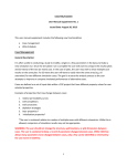
Abstract ................................................................................................................................................ 1
Contents ............................................................................................................................................... 2
Figures .................................................................................................................................................. 3
Tables ................................................................................................................................................... 3
1
Terms and definitions ................................................................................................................... 4
2
References ..................................................................................................................................... 4
3
Introduction.................................................................................................................................... 5
3.1 Hardware content .................................................................................................................. 5
3.2 Web content .......................................................................................................................... 6
3.2.1
Software Development Kit content ........................................................................ 6
3.2.1.1
Tools .................................................................................................. 6
3.2.1.2
SDK documents ................................................................................. 6
3.2.1.3
SDK source code examples (created with Keil IDE) ......................... 7
3.3 DA14580 – DA14581 basic kit .............................................................................................. 9
3.3.1
Differences between the DA14580/580/583 .......................................................... 9
3.4 Pinning ................................................................................................................................ 11
3.4.1
PCB design and functionalities ............................................................................ 12
3.4.2
Schematics and layouts ....................................................................................... 14
3.4.2.1
DA1580DEVKT-B_va layout ............................................................ 14
3.4.2.2
DA1581DEVKT-B_va layout ............................................................ 16
3.4.2.3
DA1583DEVKT-B_va layout ............................................................ 18
3.4.3
Configuring the DA14580/581 basic kit-board by jumper settings ...................... 20
3.4.4
Configuring the DA14583 basic kit-board by jumper settings ............................. 22
4
Installation of tools and drivers ................................................................................................. 23
4.1 Keil ...................................................................................................................................... 23
4.2 SEGGER Jlink driver ........................................................................................................... 24
4.3 FTDI driver .......................................................................................................................... 24
4.4 Tera Term ........................................................................................................................... 25
5
Quick start: Downloading software ........................................................................................... 26
5.1 Software downloaded via Keil IDE: USB (via SWD) to SRAM ........................................... 27
6
Using the demo kit ...................................................................................................................... 29
6.1 Run an example on the DA14580/581 /583 ........................................................................ 29
7
Power Management: measuring current ................................................................................... 34
Appendix A Layout DA14580/581 .................................................................................................... 36
Appendix B Connections of J10 and J11 ........................................................................................ 36
Appendix C Layout DA14583 ........................................................................................................... 37
Appendix D Connections of J10 ...................................................................................................... 37
Appendix E Using the smart snippets CLI ...................................................................................... 38
Appendix F Issues with opening a project for the first time ......................................................... 39
F.1 Issue description: ................................................................................................................ 39
F.2 Possible causes: ................................................................................................................. 39
F.3 Under which circumstances user will encounter this error:................................................. 39
User manual
CFR0012-00 Rev 2
Revision 2.3
2 of 44
03-Jun-2015
© 2015 Dialog Semiconductor
UM-B-025
DA14580/581/583 Bluetooth Smart development kit – Basic
F.4
Proposed solution: .............................................................................................................. 39
Appendix G ‘Blinky’ Test software .................................................................................................. 40
Appendix H Latency Timer of FTDI cable ....................................................................................... 42
8
Web-Links .................................................................................................................................... 43
9
Revision history .......................................................................................................................... 43
Contacting Dialog Semiconductor .................................................................................................. 44
Figures
Figure 1: DEVKT – Basic Kit ................................................................................................................. 5
Figure 2: QFN40 pin assignment from datasheet ............................................................................... 11
Figure 3: Components on PCB top layer of the DA14580/581Basic kit .............................................. 12
Figure 4: Topview of PCB DA14580/581 with components and functionalities .................................. 12
Figure 5: Components on PCB top layer of the DA14583 Basic kit .................................................... 13
Figure 6: Topview of PCB DA14583 with components and functionalities ......................................... 13
Figure 7: DA14580DEVKT-B_vb part 1 ............................................................................................... 14
Figure 8: DA14580DEVKT-B_vb part 2 ............................................................................................... 15
Figure 9: DA1581DEVKT-B_va part 1 ................................................................................................. 16
Figure 10: DA1581DEVKT-B_va part 2 ............................................................................................... 17
Figure 11: DA1583DEVKT-B_va part 1 ............................................................................................... 18
Figure 12: DA1583DEVKT-B_va part 2 ............................................................................................... 19
Figure 13: DA14580/581 (Fabrication Default) UART boot settings (Tx P0_4 and Rx P0_5) ............ 20
Figure 14: DA14580/581Boot from external SPI memory ................................................................... 20
Figure 15: Data direction of UART within J4 ....................................................................................... 20
Figure 16: DA14580/581 layout of headers J4 and J6 ........................................................................ 21
Figure 17: (Fabrication Default) DA14583 UART boot settings (Tx P0_4 and Rx P0_5) ................... 22
Figure 18: Data direction of UART within J4 ....................................................................................... 22
Figure 19: DA14583 Layout of headers J4 and J6 .............................................................................. 22
Figure 20: Block diagram with different memory locations .................................................................. 26
Figure 21: Setup of DA14580/581 DEVKT – BASIC during power measurement .............................. 34
Figure 22: Setup of DA14583 DEVKT – BASIC during power measurement ..................................... 34
Figure 23: A general overview of the DA14581 development board .................................................. 36
Figure 24: DA14580/581 Connection diagram of J10 and J11 ........................................................... 36
Figure 25: A general overview of the DA14583 development board .................................................. 37
Figure 26: DA14583 Connection diagram of J10 ................................................................................ 37
Figure 27: Open the CLI of SmartSnippets ......................................................................................... 38
Figure 28: SmartSnippets output ......................................................................................................... 38
Figure 29: FTDI Latency Timer ........................................................................................................... 42
Tables
Table 1: Content of the DEVKT – Basic Kit ........................................................................................... 5
Table 2: SDK Examples ........................................................................................................................ 7
Table 3: DA14580 .................................................................................................................................. 9
Table 4: DA14581 .................................................................................................................................. 9
Table 5: DA14583 ................................................................................................................................ 10
Table 6: SPI connections..................................................................................................................... 11
Table 7: Installation tools and drivers .................................................................................................. 23
Table 8: Way of Working (WoW) loading ‘Blinky’-code ....................................................................... 27
Table 9: Run an example on DA14580/581/583 ................................................................................. 29
User manual
CFR0012-00 Rev 2
Revision 2.3
3 of 44
03-Jun-2015
© 2015 Dialog Semiconductor
UM-B-025
DA14580/581/583 Bluetooth Smart development kit – Basic
1
Terms and definitions
BLE
CS
DK
EEPROM
FTDI
GPIO
OTP
PCB
QFN
SDK
SPI
SRAM
SWD
USB
UART
WLCSP
WoW
2
1.
2.
3.
4.
5.
6.
7.
8.
9.
10.
11.
12.
Bluetooth Low Energy
Chip Select
Development Kit
Electrically Erasable Programmable Memory
Brand name of USB – UART interface
General Purpose Input Output
One Time Programmable
printed circuit board
Quad-Flat No-leads
Software Development Kit
Serial Peripheral Interface
Static Random Access Memory
Serial Wire Debug
Universal Serial Bus
Universal Asynchronous Receiver/Transceiver
Wafer Level Chip Scale Packaging
Way of Working
References
DA14580, Datasheet, Dialog Semiconductor
DA14581, Datasheet, Dialog Semiconductor
UM-B-015, DA14580_581_583 Software Architecture, Dialog Semiconductor
DA14580 CB PXI QFN40 layout, Dialog Semiconductor
DA14580_CB_PXI_QFNP40, Dialog Semiconductor
DA14580_CB_PXI_WLCSP, Dialog Semiconductor
DA14580_CB_PXI_WLCSP_layout, Dialog Semiconductor
DA14580_MB_VB_layout, Dialog Semiconductor
DA14580_CB PXI_QFN48, Dialog Semiconductor
UM-B-005, DA14580_581_583 Peripheral Examples, Dialog Semiconductor
UM-B-010, DA14580_581_583 Proximity application, Dialog Semiconductor
AN-B-015 DA14580 Supply current measurement, Dialog Semiconductor
User manual
CFR0012-00 Rev 2
Revision 2.3
4 of 44
03-Jun-2015
© 2015 Dialog Semiconductor
UM-B-025
DA14580/581/583 Bluetooth Smart development kit – Basic
3
Introduction
DA14580/581/583 is a Bluetooth Smart chip, working with extremely low power while providing
world-class RF performance, a small footprint and flexible peripheral configurations for a wide range
of applications. The development kit includes a set of hardware (e.g. development board with onboard debugger), a Software Development Kit (SDK) (e.g. development tools, source code examples
documents and so on) along with documentation. This document helps users to set up
hardware/software development environment, install required software and quickly start product
development with the help of example source code.
Web content can be downloaded at: www.dialog-semiconductor.com/support.
Product information about the DA14580, DA14581 and DA14583 can be found at:
www.dialog-semiconductor.com/products/bluetooth-smart/smartbond-da14580.
www.dialog-semiconductor.com/products/bluetooth-smart/smartbond-development-tools/da14581development-kit-basic.
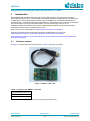
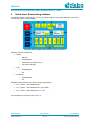
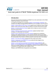
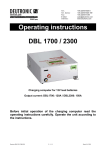
3.1
Hardware content
In Figure 1 the kit components are shown and in Table 1 the parts are printed.
Figure 1: DEVKT – Basic Kit
Table 1: Content of the DEVKT – Basic Kit
DA14580/581/583 basic board
Battery: CR2032
USB Mini USB Cable
Note 1
Kits are not pre-programmed so must be programmed before use!
User manual
CFR0012-00 Rev 2
Revision 2.3
5 of 44
03-Jun-2015
© 2015 Dialog Semiconductor
UM-B-025
DA14580/581/583 Bluetooth Smart development kit – Basic
3.2
Web content
3.2.1 Software Development Kit content
3.2.1.1
Tools
Web-link: www.dialog-semiconductor.com/support
SmartSnippets
SmartSnippets is a framework of PC based tools to control DA14580/581/583 development kit,
consisting of
● OTP Programmer: Tool for OTP memory programming
● UART booter: Tool for downloading hex files to DA14580/581 SRAM over UART
● SPI & I2C memory programmer: Tool for SPI flash and I2C EEPROM programming
ConnectionManager
Connection Manager is a PC based software tool to control the link layer of the DA14580/581/583,
with the following capabilities:
●
●
●
●
●
Functional in Peripheral and Central role
Set advertising parameters
Set connection parameters
Reading from Attribute database
Perform production test commands
3.2.1.2
●
●
●
●
●
●
●
●
●
●
●
●
SDK documents
UM-B-003, DA14580_581_583 Software development guide
UM-B-004, DA14580_581_583 Peripheral drivers
UM-B-005, DA14580_581_583 Peripheral examples
UM-B-006, DA14580 Sleep mode configuration
UM-B-007, DA14580 Software Patching over the Air (SPOTA)
UM-B-008, DA14580_581_583 Production test tool
UM-B-010, DA14580_581_583 Proximity application
UM-B-011, DA14580 Memory map – scatter file
UM-B-012, DA14580 Secondary boot loader
UM-B-013, DA14580 External Processor Interface over SPI
UM-B-014, DA14580_581 Development Kit
UM-B-015, DA14580_581_583 Software architecture
User manual
CFR0012-00 Rev 2
Revision 2.3
6 of 44
03-Jun-2015
© 2015 Dialog Semiconductor
UM-B-025
DA14580/581/583 Bluetooth Smart development kit – Basic
3.2.1.3
SDK source code examples (created with Keil IDE)
Web-link:
● dk_apps. This folder holds all the necessary folders needed for DA14580/581 application
development.
o dk_apps\keil_projects\proximity
The folder contains the following subfolders and in each one of them resides the respective
project file:
Table 2: SDK Examples
Folder
Project File
Description
prox_monitor_ext\Keil_4
prox_monitor_ext.uvproj
prox_monitor_ext_581.uvproj
Proximity Monitor (External processor
configuration)
prox_monitor_ext\Keil_5
prox_monitor_ext_583.uvproj
prox_monitor_ext.uvprojx
prox_monitor_ext_581.uvprojx
prox_monitor_ext_583.uvprojx
prox_reporter_ext\Keil_4
prox_reporter_ext.uvproj
prox_reporter_ext_581.uvproj
prox_reporter_ext_583.uvproj
prox_reporter_ext\Keil_5
Proximity Reporter (External processor
configuration)
prox_reporter_ext.uvprojx
prox_reporter_ext_581.uvprojx
prox_reporter_ext_583.uvprojx
prox_reporter\Keil_4
prox_reporter.uvproj
prox_reporter_581.uvproj
prox_reporter_583.uvproj
prox_reporter\Keil_5
Proximity Reporter (Integrated
processor configuration)
prox_reporter.uvprojx
prox_reporter_581.uvprojx
prox_reporter_583.uvprojx
prox_monitor_ext_usb\Keil_4
prox_monitor_ext_usb.uvproj
prox_monitor_ext_usb_581.uvproj
prox_monitor_ext_usb_583.uvproj
prox_monitor_ext_usb\Keil_5
Proximity Monitor (External processor
configuration)
Version for USB dongle
prox_monitor_ext_usb.uvprojx
prox_monitor_ext_usb_581.uvprojx
prox_monitor_ext_usb_583.uvprojx
prox_reporter_ext_usb\Keil_4
prox_reporter_ext_usb\Keil_5
prox_reporter_ext_usb.uvproj
prox_reporter_ext_usb _581.uvproj
Proximity Reporter (External processor
configuration)
prox_reporter_ext_usb _583.uvproj
prox_reporter_ext_usb.uvprojx
Version for USB dongle
prox_reporter_ext_usb
_581.uvprojx
prox_reporter_ext_usb
_583.uvprojx
prox_reporter_ext_spi\Keil_4
prox_reporter_ext_spi\Keil_5
prox_reporter_ext_spi.uvproj
prox_reporter_ext_spi_581.uvproj
Proximity Reporter (External processor)
SPI version
prox_reporter_ext_spi_583.uvproj
prox_reporter_ext_spi.uvprojx
prox_reporter_ext_spi_581.uvprojx
prox_reporter_ext_spi_583.uvprojx
User manual
CFR0012-00 Rev 2
Revision 2.3
7 of 44
03-Jun-2015
© 2015 Dialog Semiconductor
UM-B-025
DA14580/581/583 Bluetooth Smart development kit – Basic
o
dk_apps\keil_projects\prod_test: This folder includes the source code of the production
test firmware. Refer to UM-B-008_DA14580_581_583_Production_test_tool.pdf for more
information how to build and use it.
● host_apps: This folder holds the DA14580/581/583 PC applications:
o
o
o
host_apps\windows\proximity: This folder includes two Windows C applications, with each
one acting as part of a proximity monitor and a proximity reporter application. They are
placed in subfolders monitor and reporter respectively. For details, please read the DA14580
Proximity Application Guide.
host_binaries\windows\proximity: This folder includes two pre-compiled Windows
executables which correspond to the C applications described right above and are included
for user convenience.
peripheral_examples: This folder includes sample code of how to use the peripheral blocks
of the DA14580 (e.g. UART, SPI, I2C etc.) bundled to a demo-kit. For details, please refer to
[9].
● tools:
o
tools\prod_test\prod_test_cmds: This folder includes the source code of the production
test tool. Refer to UM-B-008_DA14580_581_583_Production_test_tool.pdf for more
information how to build and use it.
User manual
CFR0012-00 Rev 2
Revision 2.3
8 of 44
03-Jun-2015
© 2015 Dialog Semiconductor
UM-B-025
DA14580/581/583 Bluetooth Smart development kit – Basic
3.3
DA14580 – DA14581 basic kit
3.3.1
Differences between the DA14580/580/583
The motherboard of the DEVKT – Pro will not change. Only the daughters of the DA14580/581/583
are different.
Table 3: DA14580
General
Purpose
I\O’s
Package
WL-CSP34
12
2.5x2.5x0.5mm,
pitch 0.4mm
QFN40
24
5x5x0.9mm,
pitch 0.4mm
Product
QFN48
Memory size
ROM
84kBytes
OTP
32kBytes
RAM
50kBytes
32
6x6x0.9mm,
pitch 0.4mm
Key Features
Bluetooth 4.0
+ 4.1
Cortex M0
application
processor
Power supply
0.9 - 3.3V
Single pin RF
I/O
Rich set of
analog and
digital
peripherals
Applications
Beacon &
Proximity
Health &
Fitness
HID
Smart Home
Table 4: DA14581
Product
Memory size
WL-CSP34
General
Purpose
I\O’s
12
ROM
84kBytes
OTP
32kBytes
RAM
50kBytes
QFN40
User manual
CFR0012-00 Rev 2
24
Package
2.5x2.5x0.5mm,
pitch 0.4mm
Key Features
Bluetooth 4.0
+ 4.1
Cortex M0
application
processor
Power supply
0.9 - 3.3V
Single pin RF
I/O
Rich set of
analog and
digital
peripherals
8 connections
Optimized
boot time
5x5x0.9mm,
pitch 0.4mm
Revision 2.3
9 of 44
Applications
Wireless
charging
(A4WP)
HCI
03-Jun-2015
© 2015 Dialog Semiconductor
UM-B-025
DA14580/581/583 Bluetooth Smart development kit – Basic
Table 5: DA14583
Product
Memory size
QFN40
Note 1
Flash
1 Mbit
(128kBytes)
ROM
84kBytes
OTP
32kBytes
RAM
50kBytes
General
Purpose
I\O’s
24
Package
5x5x0.9mm,
pitch 0.4mm
Key Features
Applications
Bluetooth 4.0
+ 4.1
Cortex M0
application
processor
Power supply
2.35 - 3.3V
Single pin RF
I/O
Rich set of
analog and
digital
peripherals
Beacon &
Proximity
Health &
Fitness
HID
Smart Home
The only hardware difference between the DEVKT -Basic 14580 and the DEFKT -Basic 14581, is the
design in of QFN48 (580) and the QFN40 (580/581). The silkscreen may have small textual
differences.
Remark: DA14583 will run in BUCK mode only!
User manual
CFR0012-00 Rev 2
Revision 2.3
10 of 44
03-Jun-2015
© 2015 Dialog Semiconductor
UM-B-025
DA14580/581/583 Bluetooth Smart development kit – Basic
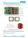
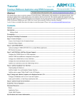
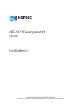
3.4
Pinning
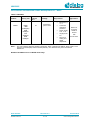
In Figure 2 the pinout of the DA14583 is shown. New, compared to the DA14580/581, are the
connections to the internal SPI flash memory.
Figure 2: QFN40 pin assignment from datasheet
Table 6: SPI connections
port
DA14583
function
remark
P2_0
P2_9
P2_4
P2_3
SPI_CLK
SPI_DI
SPI_DO
SPI_EN
VCC_FLASH
GND
SCLK (Note 2)
MOSI (Note 2)
MISO (Note 2)
not to be used for external SPI (!)
power for internal Flash Memory
Note 2
shared with internal flash memory
When external SPI components are used, SPI_EN is occupied for internal use. Another pin should
be chosen for SPI_EN of the external component.
By using a Secondary Bootloader the proper pins are programmed to load the booting software from
the SPI-memory at startup.
User manual
CFR0012-00 Rev 2
Revision 2.3
11 of 44
03-Jun-2015
© 2015 Dialog Semiconductor
UM-B-025
DA14580/581/583 Bluetooth Smart development kit – Basic
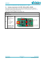
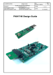
3.4.1
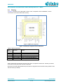
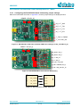
PCB design and functionalities
Figure 3: Components on PCB top layer of the DA14580/581Basic kit
The different components and functionalities are shown in Figure 4.
A larger picture is shown in Appendix A
Led J9
J2 Tag
connect
3V3
batt
GND3
RESET
SW1
J10
GND2
USB
DA14580
or DA14581
Led D1
GND1
Led D5
Led D4
J8
OTP enable
U5 memory
Flash 2Mbit
28p
header
J4/J6
J11
Figure 4: Topview of PCB DA14580/581 with components and functionalities
User manual
CFR0012-00 Rev 2
Revision 2.3
12 of 44
03-Jun-2015
© 2015 Dialog Semiconductor
UM-B-025
DA14580/581/583 Bluetooth Smart development kit – Basic
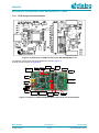
The top-screen layer of the DA14583 Basic Kit PCB is shown in Figure 5.
Figure 5: Components on PCB top layer of the DA14583 Basic kit
Led J9
J2 Tag
connect
3V3
batt
GND3
RESET
SW1
J10
GND2
USB
DA14583
Led D1
GND1
Led D5
Led D4
J8
OTP programming
voltage enable
28p
header
J4
Figure 6: Topview of PCB DA14583 with components and functionalities
User manual
CFR0012-00 Rev 2
Revision 2.3
13 of 44
03-Jun-2015
© 2015 Dialog Semiconductor
UM-B-025
DA14580/581/583 Bluetooth Smart development kit – Basic
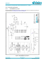
3.4.2
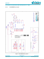
3.4.2.1
Schematics and layouts
DA1580DEVKT-B_va layout
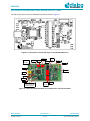
For the schematics and layout of the board in full detail, please refer to the respective documents on
the portal. See link: www.dialog-semiconductor.com/support.
Figure 7: DA14580DEVKT-B_vb part 1
User manual
CFR0012-00 Rev 2
Revision 2.3
14 of 44
03-Jun-2015
© 2015 Dialog Semiconductor
UM-B-025
DA14580/581/583 Bluetooth Smart development kit – Basic
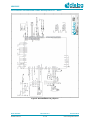
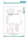
Figure 8: DA14580DEVKT-B_vb part 2
User manual
CFR0012-00 Rev 2
Revision 2.3
15 of 44
03-Jun-2015
© 2015 Dialog Semiconductor
UM-B-025
DA14580/581/583 Bluetooth Smart development kit – Basic
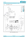
3.4.2.2
DA1581DEVKT-B_va layout
Figure 9: DA1581DEVKT-B_va part 1
User manual
CFR0012-00 Rev 2
Revision 2.3
16 of 44
03-Jun-2015
© 2015 Dialog Semiconductor
UM-B-025
DA14580/581/583 Bluetooth Smart development kit – Basic
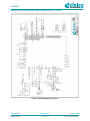
Figure 10: DA1581DEVKT-B_va part 2
User manual
CFR0012-00 Rev 2
Revision 2.3
17 of 44
03-Jun-2015
© 2015 Dialog Semiconductor
UM-B-025
DA14580/581/583 Bluetooth Smart development kit – Basic
3.4.2.3
DA1583DEVKT-B_va layout
Figure 11: DA1583DEVKT-B_va part 1
User manual
CFR0012-00 Rev 2
Revision 2.3
18 of 44
03-Jun-2015
© 2015 Dialog Semiconductor
UM-B-025
DA14580/581/583 Bluetooth Smart development kit – Basic
Figure 12: DA1583DEVKT-B_va part 2
User manual
CFR0012-00 Rev 2
Revision 2.3
19 of 44
03-Jun-2015
© 2015 Dialog Semiconductor
UM-B-025
DA14580/581/583 Bluetooth Smart development kit – Basic
3.4.3
Configuring the DA14580/581 basic kit-board by jumper settings
Different functionalities are shown in Appendix A, and the jumper settings are displayed below.
POWER LED (P1_0)
P0_4 > T_RxD
P0_5 < T_TxD
P0_6 > T_CTS
P0_7 < T_RTS
T_TMS <> SWDIO
T_TCK > SW_CLK
Figure 13: DA14580/581 (Fabrication Default) UART boot settings (Tx P0_4 and Rx P0_5)
POWER LED (P1_0)
SPI_MISO = P0_5
SPI_MOSI = P0_6
P0_3 = SPI_CS
P0_0 = SPI_Cl
BAT_SEL = SPI_SUP
T_TMS = SWDIO (P1_5)
T_TCK = SW_CLK (P1_4)
P0_4 (TxD)
(RxD)
P0_5 (RxD)
(TxD)
P0_6 (RTS)
(CTS)
P0_7 (CTS)
(RTS)
USB
DA14580/581/583
Figure 14: DA14580/581Boot from external SPI memory
Figure 15: Data direction of UART within J4
User manual
CFR0012-00 Rev 2
Revision 2.3
20 of 44
03-Jun-2015
© 2015 Dialog Semiconductor
UM-B-025
DA14580/581/583 Bluetooth Smart development kit – Basic
Pin 1.
gnd
gnd
VBAT_580
RST
P1_3
P1_1
P0_2
P1_2
P1_0
P0_1
T_RxD
T_TxD
P0_4
SPI-MISO - P0_5
SPI-MOSI - P0_6
P0_7
P0_3
P0_0
BATT SEL
T_CTS
T_RTS
SPI_CS
SPI_CLK
SPI_SUPPLY
T_TMS
T_TCK
SWDIO (P1_5)
SW_CLK (P1_4)
Figure 16: DA14580/581 layout of headers J4 and J6
Example: when jumper J4 (27-28) is placed, connection T_CK = SW_CLK is made.
On this board only the Buck mode is used. A choice can be made between 3V3 (via USB) (J5 1-2) or
Vdd (via a coin cell) (J5 2-3). The battery (coin cell) is placed in the battery-socket on the back of the
PCB.
No battery is needed when running via the USB-mini-cable.
Note 1
The DA14580 is equipped with a QFN48 device and the DA14581 has a QFN40 die mounted.
User manual
CFR0012-00 Rev 2
Revision 2.3
21 of 44
03-Jun-2015
© 2015 Dialog Semiconductor
UM-B-025
DA14580/581/583 Bluetooth Smart development kit – Basic
3.4.4
Configuring the DA14583 basic kit-board by jumper settings
Different functionalities are shown in Appendix A, and the jumper settings are displayed below.
POWER LED (P1_0)
P0_4 > T_RxD
P0_5 < T_TxD
P0_6 > T_CTS
P0_7 < T_RTS
BATS <> SPI_SU
T_TMS <> SWDIO
T_TCK > SW_CLK
P0_4 (TxD)
(RxD)
P0_5 (RxD)
(TxD)
P0_6 (RTS)
(CTS)
P0_7 (CTS)
(RTS)
USB
DA14580/581/583
Figure 17: (Fabrication Default) DA14583 UART boot settings (Tx P0_4 and Rx P0_5)
Figure 18: Data direction of UART within J4
Pin 1.
gnd
gnd
VBAT_580
RST
P1_3
P1_1
P0_2
P1_2
P1_0
P0_1
T_RxD
T_TxD
P0_4
P0_5
P0_6
P0_7
P0_3
P0_0
BATT SEL
T_CTS
T_RTS
n.c.
n.c.
SPI_SUPPLY
T_TMS
T_TCK
SWDIO (P1_5)
SW_CLK (P1_4)
Figure 19: DA14583 Layout of headers J4 and J6
Example: when jumper J4 (27-28) is placed, connection T_CK = SW_CLK is made.
On this board only the Buck mode is used. A choice can be made between 3V3 (via USB) (J5 1-2) or
Vdd (via a coin cell) (J5 2-3). The battery (coin cell) is placed in the battery-socket on the back of the
PCB.
No battery is needed when running via the USB-mini-cable.
Note 1
The DA14583 is equipped with a QFN40 device.
I
User manual
CFR0012-00 Rev 2
Revision 2.3
22 of 44
03-Jun-2015
© 2015 Dialog Semiconductor
UM-B-025
DA14580/581/583 Bluetooth Smart development kit – Basic
4
Installation of tools and drivers
To install the Software development environment, please follow the steps as shown in Table 7.
Table 7: Installation tools and drivers
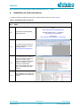
4.1
Keil
Keil:
https://www.keil.com/download/product/
4.1.1
Keil MDK-ARM Version 5 – Installation:
Download and install Keil MDKARM uVision IDE.
http://www2.keil.com/mdk5/install
Starters Guide:
http://www.keil.com/uvision/ide_ov_starting.asp
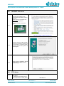
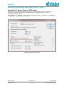
4.1.2
4.1.3
4.1.4
For uVision Version you have to
install the ARM Cortex M profile
package (see also
http://www.keil.com/dd2/Pack/)
You should see a list of packs as
shown on the right. If you do not
see this list, please click the
“Packs” menu item and select the
“Check for Updates” option to
download an updated list.
Click on the “Install” button to the
right of “Keil::ARMCortex_DFP”
package.
If the installation is successful, the
pack installer window should look
like this.
User manual
CFR0012-00 Rev 2
Revision 2.3
23 of 44
03-Jun-2015
© 2015 Dialog Semiconductor
UM-B-025
DA14580/581/583 Bluetooth Smart development kit – Basic
4.2
SEGGER Jlink driver
Download and install the Jlink
software & documentation pack for
Windows.
Please note that your SEGGER Jlink
serial number is required for
downloading.
Use sticker-number on backside of
board.
4.2.1
.
http://www.segger.com/jlink-software.html
4.2.2
4.2.3
4.3
4.3.1
In order to have the USB controller
properly recognized by Windows as
a J-Link device, you have to install
the driver with the settings shown in
the side figure.
At the end of the installation, please
tick the IDE (Keil MDK Vxx) that
you are using.
FTDI driver
The Development Kit uses the
D2xx driver.
For Windows, this driver is part of
the Combined Driver Model (CDM)
User manual
CFR0012-00 Rev 2
USB Drivers:
Revision 2.3
24 of 44
03-Jun-2015
© 2015 Dialog Semiconductor
UM-B-025
DA14580/581/583 Bluetooth Smart development kit – Basic
driver.
(It is recommended that the latest driver
available from the FTDI page is used.)
http://www.ftdichip.com/Drivers/D2XX.htm
Installation Guide:
http://www.ftdichip.com/Support/Documents/InstallG
uides.htm
Latency Timer: see Appendix H
4.4
4.4.1
Tera Term
Download and install Tera Term on
your PC.
User manual
CFR0012-00 Rev 2
Tera Term:
http://en.sourceforge.jp/projects/ttssh2/releases/
Revision 2.3
25 of 44
03-Jun-2015
© 2015 Dialog Semiconductor
UM-B-025
DA14580/581/583 Bluetooth Smart development kit – Basic
5
Quick start: Downloading software
The DEVKT –Basic is equipped with, on the chip, SRAM (42k) and OTP (32k). Mounted on the board
is external SPI flash memory (2Mbit).
Figure 20: Block diagram with different memory locations
Software can be downloaded to:
SRAM
o
Keil IDE
o
SmartSnippets
o
Command Line Interface (CLI)
o
Connection Manager
OTP
o
SmartSnippets
o
CLI
SPI (flash)
o
SmartSnippets
o
CLI
Example: loading software (hex-file) by using SmartSnippets
PC -> UART -> DA14580/581/583
PC -> UART -> DA14580/581/583 -> SPI (flash)
PC -> UART -> DA14580/581/583 -> OTP
For the settings of the jumpers see Figure 13.
User manual
CFR0012-00 Rev 2
Revision 2.3
26 of 44
03-Jun-2015
© 2015 Dialog Semiconductor
UM-B-025
DA14580/581/583 Bluetooth Smart development kit – Basic
5.1
Software downloaded via Keil IDE: USB (via SWD) to SRAM
Way of working: the Keil IDE (uVision 5.12) is used to load software into the board. Software is
downloaded to SRAM through SWD (Serial Wire Debug). After downloading the software (see 4.1),
the software can be debugged via the same IDE.
Table 8: Way of Working (WoW) loading ‘Blinky’-code
Preparations
This chapter shows the user how to quickly set up the software development environment of the BLE (Bluetooth
Low Energy) demo
Attach mini USB
cable to PC and
demo board.
Functionality of this
cable:
5.1.1
●
●
●
●
POWER
LED
P0_4 > T_RxD
power
P0_5 < T_TxD
programming
debugging
UART
mini
USB
T_TMS <> SWDIO
The DEVKT –B 581
and DEVKT –B 583
can be programmed
in the same way.
User manual
CFR0012-00 Rev 2
T_TCK > SW_CLK
Revision 2.3
27 of 44
03-Jun-2015
© 2015 Dialog Semiconductor
UM-B-025
DA14580/581/583 Bluetooth Smart development kit – Basic
5.1.2
5.1.3
5.1.4
5.1.5
Add 4 jumpers, as
shown in the photo of
5.1.1.
Jumpers: J5 (1-2) ‘POWER’ = left-side,
J9 ‘LED’,
J4 (11-12) ‘P0_4 > T_RxD’,
J4 (13-14) ‘P0_5 < T_TxD’,
‘TMS’ - J4 (25-26) ‘T_TMS <> SWDIO’ and
‘TCK’ - J4 (27-28) ‘T_TCK > SW_CLK’.
Start Keil IDE
software and load
‘Blinky’ example
code. Via this Blinkycode the LED on the
board starts blinking.
Also added in this
code, is the UART
sending a text string.
See 0
In file
‘periph_setup.h’
default P0_4 Tx and
P0.5 Rx are used as
UART IO-ports.
Compile and Debug
the software.
The blinking led D7 is
visible and the
TeraTerm screen is
showing ‘popping up’
lines.
Choose the right
com-port via the
Device Manager of
your PC.
User manual
CFR0012-00 Rev 2
Revision 2.3
28 of 44
03-Jun-2015
© 2015 Dialog Semiconductor
UM-B-025
DA14580/581/583 Bluetooth Smart development kit – Basic
6
Using the demo kit
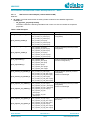
Follow these steps shown in Table 9 to easily create a working demo kit.
Table 9: Run an example on DA14580/581/583
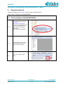
6.1
6.1.1
Run an example on the DA14580/581/583
After you download the SDK at
www.dialogsemiconductor.com/support
The source code example can be
found in the example directory
called “peripheral_examples\”.
Double click
“580_peripheral_setup.uvproj
6.1.2
6.1.3
The development environment
should look like this when the
project is opened with Keil.
Click on the “Target Options”
button
User manual
CFR0012-00 Rev 2
Revision 2.3
29 of 44
03-Jun-2015
© 2015 Dialog Semiconductor
UM-B-025
DA14580/581/583 Bluetooth Smart development kit – Basic
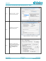
6.1.4
‘Options for Target’ → ‘Device’
-screen should look like this.
Scatterfiles (.sct) are used for
selecting memory areas.
6.1.5
scatter file selection in ‘Options for Target’
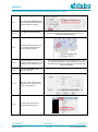
6.1.6
Make sure “J-LINK/J-Trace
Cortex” is selected as shown and
the initialization file field is set
correctly to “.\sysram.ini”.
Click on “Settings” for next
screen.
User manual
CFR0012-00 Rev 2
Revision 2.3
30 of 44
03-Jun-2015
© 2015 Dialog Semiconductor
UM-B-025
DA14580/581/583 Bluetooth Smart development kit – Basic
6.1.7
6.1.8
After clicking the “Settings”-button
above, make sure the SW Device
has been detected correctly.
Click “OK” to save the settings.
6.1.9
Build the project by pressing “F7”
key, or click the build button as
shown in following picture
6.1.10
Make sure you have a UART
connection between your PC and
a mother board, as shown in 6.1.5.
Check the “COM” number on you
PC.
6.1.11
Open the “Tera Term” serial
terminal on you PC.
6.1.12
Open Tera Term and choose a
COM port, which you have found
in step 3, and click OK
6.1.13
Choose Setup->Serial port to
configure the Baud rate etc.
User manual
CFR0012-00 Rev 2
All settings have been saved properly now, and you can
continue to build the example.
Go to the Windows Control Panel Administrative Tools
Computer Management Device Manager Ports
USB Serial Port # (connect or disconnect to see the COM
port of that module)
Revision 2.3
31 of 44
03-Jun-2015
© 2015 Dialog Semiconductor
UM-B-025
DA14580/581/583 Bluetooth Smart development kit – Basic
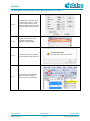
6.1.14
6.1.15
6.1.16
6.1.17
Set “Baud rate” to 115200, ”Data”
to 8 bit, ”Parity” to None, ”Stop” to
1 bit and “Flow control” to none.
Click OK. Now we have a properly
configured UART terminal on our
PC.
Go back to Keil Project. In the
menu bar, select Debug>Start/Stop Debug Session.
A dialog window pops up, like the
one on the right. Please click “OK”
Press F5 key or click execution
button as shown in following
picture, to start code execution.
User manual
CFR0012-00 Rev 2
Revision 2.3
32 of 44
03-Jun-2015
© 2015 Dialog Semiconductor
UM-B-025
DA14580/581/583 Bluetooth Smart development kit – Basic
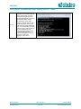
6.1.18
Then you can see a hello
message on your UART terminal
screen. That means you have
successfully programmed and
started the peripheral program on
DA14580/581 Demo board.
The peripheral_setup demo
consists of a small suite of tests
that encompasses some of the
most commonly used peripherals
such as I2C EEPROM, SPI Flash,
Rotary Encoder, audio buzzer etc.
For more detailed info and
technical details please refer to
the UM-B-005: DA14580
Peripheral Examples as well as
the source code of the
peripheral_setup demo.
User manual
CFR0012-00 Rev 2
Revision 2.3
33 of 44
03-Jun-2015
© 2015 Dialog Semiconductor
UM-B-025
DA14580/581/583 Bluetooth Smart development kit – Basic
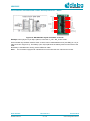
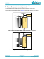
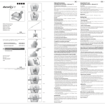
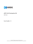
7
Power Management: measuring current
The design of this DA14580 and DA14581 DEVKT –Basic is made in such a way that the
microcontroller can be isolated completely from the rest of the board.
This is illustrated in the block diagram shown in Figure 21. Shown are the connections of the jumpers
J4, J5 and J6. For extra info see the electrical schematic in section 0.
Vdd
+
J5
Current Meter
J6/J4
-
SPI_SUPPLY
VBAT
P0_5
SPI_MOSI
P0_6
SPI_CS
P0_3
DA14580/581
SPI_MISO
SPI_CLK
P0_0
T_TMS
SWDIO
T_TCK
SW_CLK
T_RXD
P0_4
T_TXD
T_CTS
T_RTS
P0_7
GND
Figure 21: Setup of DA14580/581 DEVKT – BASIC during power measurement
J4
Vdd
+
J5
Current Meter
-
T_RXD
DA14580/581/583
VBAT
P0_4
T_TXD
P0_5
T_CTS
P0_6
T_RTS
P0_7
n.c.
n.c.
BATS
SPI_SU
T_TMS
SWDIO
T_TCK
SW_CLK
GND
Figure 22: Setup of DA14583 DEVKT – BASIC during power measurement
User manual
CFR0012-00 Rev 2
Revision 2.3
34 of 44
03-Jun-2015
© 2015 Dialog Semiconductor
UM-B-025
DA14580/581/583 Bluetooth Smart development kit – Basic
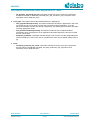
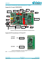
Steps how to do the power measurements:
1. Connect the Current Meter to jumper J5.
2. Mount the jumpers needed for downloading the software (see chapter 0 and chapter 5).
3. Download the software.
4. Start the software.
5. Wait till software has reached ‘Deep Sleep’.
6. Dismount all the jumpers.
Now almost all the DA14580/581/583 pins are isolated and only the current meter and GND
are connected.
7. Read the current.
For additional info: see AN-B-015 DA14580/581 Supply current measurements. [12]
See chapter 4.4 Deep Sleep current measurement.
Web-link: http://support.dialog-semiconductor.com/system/files/AN-B-015_DA14580_Current_Measurement.pdf
User manual
CFR0012-00 Rev 2
Revision 2.3
35 of 44
03-Jun-2015
© 2015 Dialog Semiconductor
UM-B-025
DA14580/581/583 Bluetooth Smart development kit – Basic
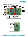
Appendix A Layout DA14580/581
Led J9
J2 Tag
connect
3V3
batt
GND3
RESET
SW1
J10
GND2
USB
DA14580 or
DA14581
Led D1
GND1
Led D5
Led D4
J8
OTP programming
voltage enable
U5 memory
Flash 2Mbit
28p
header
J4/J6
J11
Figure 23: A general overview of the DA14581 development board
P27
p29
p28
P37
p36
p26
p23
p25
p24
p35
p31
p30
p34
J11
p22
QFN48
p20
J10
p33
QFN48
QFN40
p32
p21
Appendix B Connections of J10 and J11
Figure 24: DA14580/581 Connection diagram of J10 and J11
Note 1
The QFN48 package is not available for the DA14581.
User manual
CFR0012-00 Rev 2
Revision 2.3
36 of 44
03-Jun-2015
© 2015 Dialog Semiconductor
UM-B-025
DA14580/581/583 Bluetooth Smart development kit – Basic
Appendix C Layout DA14583
Led J9
J2 Tag
connect
3V3
batt
GND3
RESET
SW1
J10
GND2
USB
DA14583
Led D1
GND1
Led D5
Led D4
28p
header
J8
OTP programming
voltage enable
J4
Figure 25: A general overview of the DA14583 development board
Note 1
The QFN48 package is not available for the DA14581.
p21
p23
p25
P27
p29
p20
p22
p24
p26
p28
Appendix D Connections of J10
J10
QFN40
Figure 26: DA14583 Connection diagram of J10
User manual
CFR0012-00 Rev 2
Revision 2.3
37 of 44
03-Jun-2015
© 2015 Dialog Semiconductor
UM-B-025
DA14580/581/583 Bluetooth Smart development kit – Basic
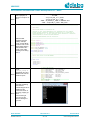
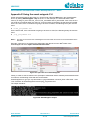
Appendix E Using the smart snippets CLI
All the information/syntaxes about the CLI can be found under the HELP tab in the SmartSnippets
GUI or by writing Smartsnippets –help in the CLI. In this example, it is assumed that the SPI
memory is using P0_0 as SCK, P0_3 as CS, P0_5 as MISO and P0_6 as MOSI. First of all, the CLI
can send the commands either via UART or JTAG according to the binary file that has been loaded.
On the one hand, if the commands are going to be sent via UART, the following binary file must be
used:
● flash_programmer.bin
On the other hand, if the commands are going to be sent via JTAG, the following binary file must be
used:
● jtag_programmer.bin
Note 2
The files can be found in the SmartSnippets resources folder and must be to be downloaded into the
DA14580.
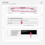
Secondly, open the CLI by pushing the Shift button and right click on the ‘bin’ folder of the
SmartSnippet and select ‘Open command window here’:
Figure 27: Open the CLI of SmartSnippets
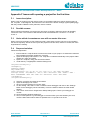
Finally, in order to write a value 0x1347 (example of a Bluetooth device address) at the address 0x93
for instance, the following command line can be written:
SmartSnippets.exe -type spi -chip DA14580-01 -jtag 228202458 -cmd write_field -offset 0x93 - data
1347 -firmware "D:\SmartSnippets\resources\jtag_programmer.bin"
The output should be:
Figure 28: SmartSnippets output
User manual
CFR0012-00 Rev 2
Revision 2.3
38 of 44
03-Jun-2015
© 2015 Dialog Semiconductor
UM-B-025
DA14580/581/583 Bluetooth Smart development kit – Basic
Appendix F Issues with opening a project for the first time
F.1
Issue description:
When a user is working on a Keil uVision project, it can happen that some entries are be missing in
the .uvopt file. If this happens, then when the user clicks on the button 'settings' (options{debug tag})
with the{J-LINK/J-TRACE Cortex} selected, uVision crashes.
F.2
Possible causes:
Some important information concerning the j-link driver is missing: calling the driver’s dll probably
causes the crash. The versions of Keil uVision found to be affected are: versions 5.11.1.0 and
5.10.0.2.
F.3
Under which circumstances user will encounter this error:
When a local GIT repository is first created, this file (.uvopt) does not exist, since it is not included in
the remote repository. When the user opens the project for the first time, this file is created, but some
keys/values are missing.
F.4
Proposed solution:
Follow the steps below.
1. Ensure that the .uvopt file does not exist in the folder of your project. If it exists and crash has
been identified to happen, delete the .uvopt file.
2. Open the Keil project and close it. The .uvopt file is created automatically in the project folder
(where the .uvproj is located).
3. Open the .uvopt file, using your favorite text editor.
4. Under the key <TargetOption> add the flowing lines:
<TargetDriverDllRegistry>
<SetRegEntry>
<Number>0</Number>
<Key>JL2CM3</Key>
<Name>-U228202424 -O78 -S0 -A0 -C0 -JU1 -JI127.0.0.1 -JP0 -RST0 -N00("ARM
CoreSight SW-DP") -D00(0BB11477) -L00(0) -TO18 -TC10000000 -TP21 -TDS8007 -TDT0 TDC1F -TIEFFFFFFFF -TIP8 -TB1 -TFE0 -FO7 -FD20000000 -FC800 -FN0</Name>
</SetRegEntry>
</TargetDriverDllRegistry>
5.
6.
7.
8.
Save the .uvopt file and close the text editor.
Open the Keil project in uVision.
Click on ProjectOptions for Project ‘XXX’.
On the ‘Debug’ Tab, select J-Link / J-TRACE Cortex debugger and click on the ‘Settings’
button for the debugger (not the simulator). This is the instance where the crash would
happen.
9. The ‘Cortex JLink/JTrace Target Driver Setup’ Dialog opens. Select your debugger as
normal.
10. Close the dialog windows clicking ok.
11. Now, normal operation of j-link debugger is resumed. After you have finished your work,
close the Keil uVision IDE to allow for updates to the .uvopt file to be saved.
User manual
CFR0012-00 Rev 2
Revision 2.3
39 of 44
03-Jun-2015
© 2015 Dialog Semiconductor
UM-B-025
DA14580/581/583 Bluetooth Smart development kit – Basic
Appendix G ‘Blinky’ Test software
/**
****************************************************************************************
*
* @file main.c
*
* @brief Blinky example for DA14580/581 SDK
*
* Copyright (C) 2012. Dialog Semiconductor Ltd, unpublished work. This computer
* program includes Confidential, Proprietary Information and is a Trade Secret of
* Dialog Semiconductor Ltd. All use, disclosure, and/or reproduction is prohibited
* unless authorized in writing. All Rights Reserved.
*
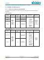
* <[email protected]> and contributors.
* ****************************************************************************************
*/
#include <stdio.h>
#include "global_io.h"
#include "common_uart.h"
#include "periph_setup.h"
#include "gpio.h"
#define LED_OFF_THRESHOLD 10000
#define LED_ON_THRESHOLD 400000
void system_init(void);
void blinky_test(void);
/**
****************************************************************************************
* @brief Main routine of the UART example
*
****************************************************************************************
*/
int main (void)
{
system_init();
periph_init();
blinky_test();
while(1);
}
/**
****************************************************************************************
* @brief System Initiialization
*
*
****************************************************************************************
*/
void system_init(void)
{
SetWord16(CLK_AMBA_REG, 0x00);
// set clocks (hclk and pclk ) 16MHz
SetWord16(SET_FREEZE_REG,FRZ_WDOG);
// stop watch dog
SetBits16(SYS_CTRL_REG,PAD_LATCH_EN,1);
// open pads
SetBits16(SYS_CTRL_REG,DEBUGGER_ENABLE,1);
// open debugger
SetBits16(PMU_CTRL_REG, PERIPH_SLEEP,0);
// exit peripheral power down
}
/**
****************************************************************************************
* @brief Blinky test fucntion
*
*
****************************************************************************************
*/
void blinky_test(void)
{
int i=0;
// Select function of the port P1.0 to pilot the LED
printf_string("\n\r\n\r");
printf_string("***************\n\r");
printf_string("* BLINKY DEMO *\n\r");
printf_string("***************\n\r");
while(1) {
User manual
CFR0012-00 Rev 2
Revision 2.3
40 of 44
03-Jun-2015
© 2015 Dialog Semiconductor
UM-B-025
DA14580/581/583 Bluetooth Smart development kit – Basic
i++;
if (LED_OFF_THRESHOLD == i) {
GPIO_SetActive( LED_PORT, LED_PIN);
printf_string("\n\r *LED ON* ");
}
if (LED_ON_THRESHOLD == i) {
GPIO_SetInactive(LED_PORT, LED_PIN);
printf_string("\n\r *LED OFF* ");
}
if (i== 2*LED_ON_THRESHOLD){
i=0;
}
}
}
User manual
CFR0012-00 Rev 2
Revision 2.3
41 of 44
03-Jun-2015
© 2015 Dialog Semiconductor
UM-B-025
DA14580/581/583 Bluetooth Smart development kit – Basic
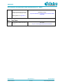
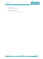
Appendix H Latency Timer of FTDI cable
If an external FTDI cable is used to burn the OTP (or to download the image into the external
memory), the Latency Timer of the FTDI cable has to be changed from 15ms to <10ms.
To change the Latency Timer:
Device Manager → COM port → Right click on the COM port chosen → Properties → Port Settings
→ Advanced → Latency Timer: set it <10ms.
Figure 29: FTDI Latency Timer
User manual
CFR0012-00 Rev 2
Revision 2.3
42 of 44
03-Jun-2015
© 2015 Dialog Semiconductor
UM-B-025
DA14580/581/583 Bluetooth Smart development kit – Basic
8
Web-Links
● Support Dialog Semiconductors e.g. datasheets and software:
http://support.dialog-semiconductor.com/resources#tools
● SmartBond DA14580:
http://www.dialog-semiconductor.com/products/bluetooth-smart/smartbond-da14580
● datasheet DA14580:
http://support.dialog-semiconductor.com
● SmartBond Reference Designs
http://www.dialog-semiconductor.com/products/bluetooth-smart/smartbond-reference-designs
9
Revision history
Revision
Date
Description
1.0
30-10-2014
Initial version for DA14580 and DA14581.
2.0
05-11-2014
Merged DA14580 documentation with the DA14581 documentation.
2.1
13-01-2015
Minor text changes and schematic updates.
2.2
01-May-2015
Updated for SDK 3.0.8
2.3.
3-Jun_2015
Updated for SDK 3.0.10 and adding DA14583 drawings
User manual
CFR0012-00 Rev 2
Revision 2.3
43 of 44
03-Jun-2015
© 2015 Dialog Semiconductor
UM-B-025
DA14580/581/583 Bluetooth Smart development kit – Basic
Status definitions
Status
Definition
DRAFT
The content of this document is under review and subject to formal approval, which may result in
modifications or additions.
APPROVED
or unmarked
The content of this document has been approved for publication.
Disclaimer
Information in this document is believed to be accurate and reliable. However, Dialog Semiconductor does not give any
representations or warranties, expressed or implied, as to the accuracy or completeness of such information. Dialog
Semiconductor furthermore takes no responsibility whatsoever for the content in this document if provided by any information
source outside of Dialog Semiconductor.
Dialog Semiconductor reserves the right to change without notice the information published in this document, including without
limitation the specification and the design of the related semiconductor products, software and applications.
Applications, software, and semiconductor products described in this document are for illustrative purposes only. Dialog
Semiconductor makes no representation or warranty that such applications, software and semiconductor products will be
suitable for the specified use without further testing or modification. Unless otherwise agreed in writing, such testing or
modification is the sole responsibility of the customer and Dialog Semiconductor excludes all liability in this respect.
Customer notes that nothing in this document may be construed as a license for customer to use the Dialog Semiconductor
products, software and applications referred to in this document. Such license must be separately sought by customer with
Dialog Semiconductor.
All use of Dialog Semiconductor products, software and applications referred to in this document are subject to Dialog
Semiconductor’s Standard Terms and Conditions of Sale, unless otherwise stated.
© Dialog Semiconductor. All rights reserved.
RoHS Compliance
Dialog Semiconductor complies to European Directive 2001/95/EC and from 2 January 2013 onwards to European Directive
2011/65/EU concerning Restriction of Hazardous Substances (RoHS/RoHS2).
Dialog Semiconductor’s statement on RoHS can be found on the customer portal https://support.diasemi.com/. RoHS
certificates from our suppliers are available on request.
Contacting Dialog Semiconductor
United Kingdom (Headquarters)
Dialog Semiconductor PLC
Phone: +44 1793 757700
North America
Dialog Semiconductor Inc.
Phone: +1 408 845 8500
Singapore
Dialog Semiconductor Singapore
Phone: +65 64 849929
Germany
Dialog Semiconductor GmbH
Phone: +49 7021 805-0
Japan
Dialog Semiconductor K. K.
Phone: +81 3 5425 4567
China
Dialog Semiconductor China
Phone: +86 21 5178 2561
The Netherlands
Dialog Semiconductor B.V.
Phone: +31 73 640 8822
Taiwan
Dialog Semiconductor Taiwan
Phone: +886 281 786 222
Korea
Dialog Semiconductor Korea
Phone: +82 2 3469 8291
Email:
[email protected]
Web site:
www.dialog-semiconductor.com
User manual
CFR0012-00 Rev 2
Revision 2.3
44 of 44
03-Jun-2015
© 2015 Dialog Semiconductor