1
MA008−010−00−00
Doc. ver.: 1.12
8051 v7.2
Cross−Assembler,
Linker, Utilities
User’s Manual
A publication of
Altium BV
Documentation Department
Copyright 2006 Altium BV
All rights reserved. Reproduction in whole or part is prohibited
without the written consent of the copyright owner.
TASKING is a brand name of Altium Limited.
The following trademarks are acknowledged:
EMUL is a trademark of NOHAU Corporation.
FLEXlm is a registered trademark of Macrovision Corporation.
Intel and ICE are trademarks of Intel Corporation.
MS−DOS and Windows are registered trademarks of Microsoft Corporation.
SUN is a trademark of Sun Microsystems Inc.
UNIX is a registered trademark of X/Open Company, Ltd.
All other trademarks are property of their respective owners.
Data subject to alteration without notice.
http://www.tasking.com
http://www.altium.com
The information in this document has been carefully reviewed and is
believed to be accurate and reliable. However, Altium assumes no liabilities
for inaccuracies in this document. Furthermore, the delivery of this
information does not convey to the recipient any license to use or copy the
software or documentation, except as provided in an executed license
agreement covering the software and documentation.
Altium reserves the right to change specifications embodied in this
document without prior notice.
CONTENTS
TABLE OF
CONTENTS
Table of Contents
CONTENTS
CONTENTS
IV
Table of Contents
V
OVERVIEW
1.1
1.2
1.3
1.4
1.5
1.6
1.7
1.8
1.9
1−1
Introduction . . . . . . . . . . . . . . . . . . . . . . . . . . . . . . . . . . . .
Environment Variables . . . . . . . . . . . . . . . . . . . . . . . . . . .
Temporary Files . . . . . . . . . . . . . . . . . . . . . . . . . . . . . . . . .
Formatting a File for a Debugger . . . . . . . . . . . . . . . . . .
File Extensions . . . . . . . . . . . . . . . . . . . . . . . . . . . . . . . . . .
Preprocessing . . . . . . . . . . . . . . . . . . . . . . . . . . . . . . . . . . .
Assembler Listing . . . . . . . . . . . . . . . . . . . . . . . . . . . . . . . .
Error Messages . . . . . . . . . . . . . . . . . . . . . . . . . . . . . . . . . .
Symbolic Debugging . . . . . . . . . . . . . . . . . . . . . . . . . . . . .
MACRO PREPROCESSOR
2.1
2.2
2.2.1
2.3
2.4
2.4.1
2.4.2
2.4.3
2.5
2.5.1
2.5.1.1
2.5.1.2
2.5.1.3
2.5.1.4
2.5.2
2.5.3
2.5.4
2.5.5
2.5.6
2.5.7
2.5.8
2.5.8.1
• • • • • • • •
Introduction . . . . . . . . . . . . . . . . . . . . . . . . . . . . . . . . . . . .
mpp51 Invocation . . . . . . . . . . . . . . . . . . . . . . . . . . . . . . .
Detailed Description of Macro Preprocessor Options .
INCLUDE Files . . . . . . . . . . . . . . . . . . . . . . . . . . . . . . . . . .
Creating and Calling Macros . . . . . . . . . . . . . . . . . . . . . .
Creating Parameterless Macros . . . . . . . . . . . . . . . . . . . .
Creating Macros with Parameters . . . . . . . . . . . . . . . . . .
Local Symbols in Macros . . . . . . . . . . . . . . . . . . . . . . . . .
The Macro Preprocessor’s Built−In Functions . . . . . . . .
Comment, Escape, Bracket and Group Functions . . . . .
Comment Function . . . . . . . . . . . . . . . . . . . . . . . . . . . . . .
Escape Function . . . . . . . . . . . . . . . . . . . . . . . . . . . . . . . . .
Bracket Function . . . . . . . . . . . . . . . . . . . . . . . . . . . . . . . .
Group Function . . . . . . . . . . . . . . . . . . . . . . . . . . . . . . . . .
METACHAR Function . . . . . . . . . . . . . . . . . . . . . . . . . . . .
Numbers and Expressions in mpp51 . . . . . . . . . . . . . . .
SET Function . . . . . . . . . . . . . . . . . . . . . . . . . . . . . . . . . . .
EVAL Function . . . . . . . . . . . . . . . . . . . . . . . . . . . . . . . . . .
UNDEF Function . . . . . . . . . . . . . . . . . . . . . . . . . . . . . . . .
Logical Expressions and String Comparisons in mpp51
Control Flow Functions and Conditional Assembly . . .
IF Function . . . . . . . . . . . . . . . . . . . . . . . . . . . . . . . . . . . . .
1−3
1−5
1−6
1−6
1−7
1−7
1−8
1−8
1−9
2−1
2−3
2−4
2−5
2−23
2−24
2−25
2−29
2−31
2−33
2−34
2−34
2−35
2−36
2−37
2−38
2−39
2−40
2−41
2−41
2−42
2−43
2−44
Table of Contents
VI
2.5.8.2
2.5.8.3
2.5.8.4
2.5.8.5
2.5.9
2.5.9.1
2.5.9.2
2.5.9.3
2.5.10
2.5.11
2.5.12
2.5.13
2.6
2.6.1
2.6.1.1
2.6.1.2
2.6.1.3
2.6.2
2.6.3
IFDEF/IFNDEF Function . . . . . . . . . . . . . . . . . . . . . . . . . .
WHILE Function . . . . . . . . . . . . . . . . . . . . . . . . . . . . . . . .
REPEAT Function . . . . . . . . . . . . . . . . . . . . . . . . . . . . . . . .
EXIT Function . . . . . . . . . . . . . . . . . . . . . . . . . . . . . . . . . .
String Manipulation Functions . . . . . . . . . . . . . . . . . . . . .
LEN Function . . . . . . . . . . . . . . . . . . . . . . . . . . . . . . . . . . .
SUBSTR Function . . . . . . . . . . . . . . . . . . . . . . . . . . . . . . . .
MATCH Function . . . . . . . . . . . . . . . . . . . . . . . . . . . . . . . .
Message Functions . . . . . . . . . . . . . . . . . . . . . . . . . . . . . .
File/Line Info Functions . . . . . . . . . . . . . . . . . . . . . . . . . .
OPTION Function . . . . . . . . . . . . . . . . . . . . . . . . . . . . . . .
Console I/O Functions . . . . . . . . . . . . . . . . . . . . . . . . . . .
Advanced mpp51 Concepts . . . . . . . . . . . . . . . . . . . . . . .
Macro Delimiters . . . . . . . . . . . . . . . . . . . . . . . . . . . . . . . .
Implied Blank Delimiters . . . . . . . . . . . . . . . . . . . . . . . . .
Identifier Delimiters . . . . . . . . . . . . . . . . . . . . . . . . . . . . . .
Literal Delimiters . . . . . . . . . . . . . . . . . . . . . . . . . . . . . . . .
Literal vs. Normal Mode . . . . . . . . . . . . . . . . . . . . . . . . . .
Algorithm for Evaluating Macro Calls . . . . . . . . . . . . . . .
ASSEMBLER
CONTENTS
3.1
3.2
3.3
3.4
Description . . . . . . . . . . . . . . . . . . . . . . . . . . . . . . . . . . . . .
Invocation . . . . . . . . . . . . . . . . . . . . . . . . . . . . . . . . . . . . . .
Asm51 Options . . . . . . . . . . . . . . . . . . . . . . . . . . . . . . . . .
Segments and Memory Allocation . . . . . . . . . . . . . . . . . .
2−46
2−47
2−48
2−49
2−50
2−50
2−51
2−52
2−53
2−54
2−54
2−55
2−56
2−56
2−56
2−57
2−58
2−60
2−62
3−1
3−3
3−3
3−4
3−9
INPUT SPECIFICATION
4−1
ASSEMBLER CONTROLS
5−1
5.1
5.2
5.3
Introduction . . . . . . . . . . . . . . . . . . . . . . . . . . . . . . . . . . . .
Overview asm51 Controls . . . . . . . . . . . . . . . . . . . . . . . . .
Description of asm51 Controls . . . . . . . . . . . . . . . . . . . . .
5−3
5−4
5−6
Table of Contents
VII
OPERANDS AND EXPRESSIONS
6.1
6.1.1
6.1.1.1
6.1.1.2
6.1.1.3
6.1.1.4
6.1.1.5
6.2
6.2.1
6.2.2
6.2.3
6.3
6.3.1
6.3.2
6.3.3
6.3.4
6.3.5
6.3.6
6.3.7
6.4
6.5
6.6
Operands . . . . . . . . . . . . . . . . . . . . . . . . . . . . . . . . . . . . . .
Operands and Addressing Modes . . . . . . . . . . . . . . . . . .
Indirect Addressing . . . . . . . . . . . . . . . . . . . . . . . . . . . . . .
Immediate Data . . . . . . . . . . . . . . . . . . . . . . . . . . . . . . . . .
Data Addressing . . . . . . . . . . . . . . . . . . . . . . . . . . . . . . . . .
Bit Addressing . . . . . . . . . . . . . . . . . . . . . . . . . . . . . . . . . .
Code Addressing . . . . . . . . . . . . . . . . . . . . . . . . . . . . . . . .
Expressions . . . . . . . . . . . . . . . . . . . . . . . . . . . . . . . . . . . .
Number . . . . . . . . . . . . . . . . . . . . . . . . . . . . . . . . . . . . . . . .
Expression String . . . . . . . . . . . . . . . . . . . . . . . . . . . . . . . .
Symbol . . . . . . . . . . . . . . . . . . . . . . . . . . . . . . . . . . . . . . . .
Operators . . . . . . . . . . . . . . . . . . . . . . . . . . . . . . . . . . . . . .
Addition and Subtraction . . . . . . . . . . . . . . . . . . . . . . . . .
Sign Operators . . . . . . . . . . . . . . . . . . . . . . . . . . . . . . . . . .
Multiplication and Division . . . . . . . . . . . . . . . . . . . . . . .
Relational Operators . . . . . . . . . . . . . . . . . . . . . . . . . . . . .
Bitwise Operators . . . . . . . . . . . . . . . . . . . . . . . . . . . . . . .
Shift Operators . . . . . . . . . . . . . . . . . . . . . . . . . . . . . . . . . .
Selection Operators . . . . . . . . . . . . . . . . . . . . . . . . . . . . . .
Segment Type of Expressions . . . . . . . . . . . . . . . . . . . . .
Predefined Symbols . . . . . . . . . . . . . . . . . . . . . . . . . . . . . .
Include Files . . . . . . . . . . . . . . . . . . . . . . . . . . . . . . . . . . . .
ASSEMBLER DIRECTIVES
7.1
7.2
7.3
7.4
7.5
• • • • • • • •
Introduction . . . . . . . . . . . . . . . . . . . . . . . . . . . . . . . . . . . .
Directives Overview . . . . . . . . . . . . . . . . . . . . . . . . . . . . .
Debugging . . . . . . . . . . . . . . . . . . . . . . . . . . . . . . . . . . . . .
Location Counter . . . . . . . . . . . . . . . . . . . . . . . . . . . . . . . .
Directives . . . . . . . . . . . . . . . . . . . . . . . . . . . . . . . . . . . . . .
6−1
6−3
6−4
6−4
6−4
6−5
6−5
6−6
6−7
6−8
6−8
6−9
6−10
6−11
6−11
6−12
6−12
6−13
6−14
6−14
6−15
6−16
6−17
7−1
7−3
7−3
7−4
7−4
7−4
Table of Contents
CONTENTS
VIII
INSTRUCTION SET
8−1
LINKER
9−1
9.1
9.2
9.3
9.4
9.5
9.6
9.6.1
9.6.2
9.6.3
9.6.4
9.6.5
9.7
9.8
9.8.1
9.8.2
9.8.3
9.8.4
9.8.5
9.9
9.10
9.11
9.11.1
9.11.2
9.11.3
9.11.4
9.12
9.12.1
9.12.2
9.12.3
9.12.4
9.12.5
Overview . . . . . . . . . . . . . . . . . . . . . . . . . . . . . . . . . . . . . .
Introduction . . . . . . . . . . . . . . . . . . . . . . . . . . . . . . . . . . . .
Naming Conventions . . . . . . . . . . . . . . . . . . . . . . . . . . . . .
Invocation . . . . . . . . . . . . . . . . . . . . . . . . . . . . . . . . . . . . . .
Link51 Options . . . . . . . . . . . . . . . . . . . . . . . . . . . . . . . . . .
Link51 Controls . . . . . . . . . . . . . . . . . . . . . . . . . . . . . . . . .
Overview link51 Controls . . . . . . . . . . . . . . . . . . . . . . . . .
Linking Controls . . . . . . . . . . . . . . . . . . . . . . . . . . . . . . . .
Locating Controls . . . . . . . . . . . . . . . . . . . . . . . . . . . . . . . .
Listing Controls . . . . . . . . . . . . . . . . . . . . . . . . . . . . . . . . .
Detailed Description of Controls . . . . . . . . . . . . . . . . . . .
Link51 Output . . . . . . . . . . . . . . . . . . . . . . . . . . . . . . . . . .
Bank Switching . . . . . . . . . . . . . . . . . . . . . . . . . . . . . . . . .
Writing Your own Bank Switch Routine . . . . . . . . . . . . .
Common Area . . . . . . . . . . . . . . . . . . . . . . . . . . . . . . . . . .
Locating Algorithm . . . . . . . . . . . . . . . . . . . . . . . . . . . . . .
Function Pointers . . . . . . . . . . . . . . . . . . . . . . . . . . . . . . . .
Resources . . . . . . . . . . . . . . . . . . . . . . . . . . . . . . . . . . . . . .
Linker Special Labels . . . . . . . . . . . . . . . . . . . . . . . . . . . . .
Linking with Libraries . . . . . . . . . . . . . . . . . . . . . . . . . . . .
Linking OMF51 Objects and Libraries . . . . . . . . . . . . . . .
Case Sensitivity . . . . . . . . . . . . . . . . . . . . . . . . . . . . . . . . .
Object Format . . . . . . . . . . . . . . . . . . . . . . . . . . . . . . . . . .
Module Selection . . . . . . . . . . . . . . . . . . . . . . . . . . . . . . . .
Backward Referencing in Libraries . . . . . . . . . . . . . . . . .
Linker Implementation . . . . . . . . . . . . . . . . . . . . . . . . . . .
Cross−Reference . . . . . . . . . . . . . . . . . . . . . . . . . . . . . . . . .
Object Format . . . . . . . . . . . . . . . . . . . . . . . . . . . . . . . . . .
Controls . . . . . . . . . . . . . . . . . . . . . . . . . . . . . . . . . . . . . . . .
Module Selection . . . . . . . . . . . . . . . . . . . . . . . . . . . . . . . .
Backward Referencing in Libraries . . . . . . . . . . . . . . . . .
9−3
9−3
9−4
9−5
9−8
9−23
9−23
9−25
9−25
9−28
9−28
9−73
9−74
9−75
9−76
9−76
9−77
9−77
9−78
9−79
9−80
9−80
9−80
9−81
9−81
9−82
9−82
9−82
9−83
9−83
9−83
Table of Contents
IX
UTILITIES
10.1
10.2
10.3
10.4
10.5
10.6
10.7
10.8
10.9
10−1
Overview . . . . . . . . . . . . . . . . . . . . . . . . . . . . . . . . . . . . . .
Archiver: ar51 . . . . . . . . . . . . . . . . . . . . . . . . . . . . . . . . . . .
Object Report Writer: dmp51 . . . . . . . . . . . . . . . . . . . . . .
Flash Utilities . . . . . . . . . . . . . . . . . . . . . . . . . . . . . . . . . . .
Formatter: ieee51 . . . . . . . . . . . . . . . . . . . . . . . . . . . . . . . .
Formatter: ihex51 . . . . . . . . . . . . . . . . . . . . . . . . . . . . . . . .
Formatter: omf51 . . . . . . . . . . . . . . . . . . . . . . . . . . . . . . . .
Formatter: srec51 . . . . . . . . . . . . . . . . . . . . . . . . . . . . . . . .
Make Utility: mk51 . . . . . . . . . . . . . . . . . . . . . . . . . . . . . .
A.OUT FILE FORMAT
1
1.1
1.2
1.3
1.4
1.5
1.6
Introduction . . . . . . . . . . . . . . . . . . . . . . . . . . . . . . . . . . . .
File Header . . . . . . . . . . . . . . . . . . . . . . . . . . . . . . . . . . . . .
Section Headers . . . . . . . . . . . . . . . . . . . . . . . . . . . . . . . . .
Section Fillers . . . . . . . . . . . . . . . . . . . . . . . . . . . . . . . . . . .
Relocation Records . . . . . . . . . . . . . . . . . . . . . . . . . . . . . .
Name Records . . . . . . . . . . . . . . . . . . . . . . . . . . . . . . . . . .
Extension Records . . . . . . . . . . . . . . . . . . . . . . . . . . . . . . .
MACRO PREPROCESSOR ERROR MESSAGES
1
2
3
4
5
Introduction . . . . . . . . . . . . . . . . . . . . . . . . . . . . . . . . . . . .
Warnings (W) . . . . . . . . . . . . . . . . . . . . . . . . . . . . . . . . . . .
Errors (E) . . . . . . . . . . . . . . . . . . . . . . . . . . . . . . . . . . . . . .
Fatal Errors (F) . . . . . . . . . . . . . . . . . . . . . . . . . . . . . . . . . .
Informational Messages (I) . . . . . . . . . . . . . . . . . . . . . . . .
ASSEMBLER ERROR MESSAGES
1
2
3
4
• • • • • • • •
Overview . . . . . . . . . . . . . . . . . . . . . . . . . . . . . . . . . . . . . .
Fatal Errors . . . . . . . . . . . . . . . . . . . . . . . . . . . . . . . . . . . . .
Assembly Errors . . . . . . . . . . . . . . . . . . . . . . . . . . . . . . . . .
Assembly Warnings . . . . . . . . . . . . . . . . . . . . . . . . . . . . . .
10−3
10−4
10−7
10−9
10−11
10−12
10−15
10−18
10−21
A−1
A−3
A−4
A−6
A−6
A−7
A−7
A−8
B−1
B−3
B−3
B−3
B−6
B−8
C−1
C−3
C−3
C−4
C−11
Table of Contents
X
LINKER ERROR MESSAGES
1
2
3
4
D−3
D−3
D−6
D−10
INTEL HEX RECORDS
E−1
MOTOROLA S−RECORDS
F−1
INDEX
CONTENTS
Overview . . . . . . . . . . . . . . . . . . . . . . . . . . . . . . . . . . . . . .
Warnings . . . . . . . . . . . . . . . . . . . . . . . . . . . . . . . . . . . . . . .
Error Messages . . . . . . . . . . . . . . . . . . . . . . . . . . . . . . . . . .
Fatal Errors . . . . . . . . . . . . . . . . . . . . . . . . . . . . . . . . . . . . .
D−1
Manual Purpose and Structure
MANUAL PURPOSE AND STRUCTURE
PURPOSE
This manual is aimed at users of the ASM51 Cross−Assembler. It assumes
that you are conversant with programming the 8051.
MANUAL STRUCTURE
Related Publications
Conventions Used In This Manual
Chapters
1. Overview
Contains an introduction to the assembler which is part of the 8051
toolchain.
2. Macro Preprocessor
Describes the action of, and options applicable to, the Macro
Preprocessor.
3. Assembler
Describes the actions and invocation of the ASM51 Cross−Assembler.
4. Input Specification
Describes the formats of the possible statements for an assembly
program.
5. Assembler Controls
Describes the syntax and semantics of all assembler controls.
6. Operands and Expressions
Describes the operands and expressions to be used in the assembler
instructions and pseudos (directives).
7. Assembler Directives
Describes the Pseudo instructions to pass information to the assembler
program.
8. Instruction Set
Gives a list of assembly language instruction mnemonics.
• • • • • • • •
XI
Manual Purpose and Structure
XII
9. Linker
Describes the action of, and options/controls applicable, to the linker
link51.
10. Utilities
Contains descriptions of the utilities supplied with the package, which
may be useful during program development.
Appendices
A. A.out File Format
Contains the layout of the output file produced by the package.
B. Macro Preprocessor Error Messages
Gives a list of error messages which can be generated by the macro
preprocessor.
MANUAL STRUCTURE
C. Assembler Error Messages
Gives a list of error messages which can be generated by the
assembler.
D. Linker Error Messages
Gives a list of error messages which can be generated by the linker.
E. Intel Hex Records
Contains a description of the Intel Hex format.
F. Motorola S−Records
Contains a description of the Motorola S−records.
Manual Purpose and Structure
RELATED PUBLICATIONS
• 8051 C Cross−Compiler User’s Manual
[TASKING, MA008−002−00−00]
• 8051 CrossView Pro Debugger User’s Manual
[TASKING, MA008−041−00−00]
CONVENTIONS USED IN THIS MANUAL
The notation used to describe the format of call lines is given below:
{}
Items shown inside curly braces enclose a list from which
you must choose an item.
[]
Items shown inside square brackets enclose items that are
optional.
|
The vertical bar separates items in a list. It can be read as
OR.
italics
Items shown in italic letters mean that you have to
substitute the item. If italic items are inside square
brackets, they are optional. For example:
filename
means: type the name of your file in place of the word
filename.
...
An ellipsis indicates that you can repeat the preceding
item zero or more times.
screen font Represents input examples and screen output examples.
bold font
Represents a command name, an option or a complete
command line which you can enter.
For example
command [option]... filename
This line could be written in plain English as: execute the command
command with the optional options option and with the file filename.
• • • • • • • •
XIII
Manual Purpose and Structure
XIV
Illustrations
The following illustrations are used in this manual:
This is a note. It gives you extra information.
This is a warning. Read the information carefully.
This illustration indicates actions you can perform with the mouse.
This illustration indicates keyboard input.
MANUAL STRUCTURE
This illustration can be read as See also". It contains a reference to
another command, option or section.
CHAPTER
1
OVERVIEW
OVERVIEW
CHAPTER
1−2
Chapter 1
1
Overview
1−3
1.1 INTRODUCTION
The TASKING 8051 toolchain can produce load files for running on the
entire 8051 family.
The assembler asm51 accepts programs written according to the Intel
assembly language specification for the 8051. A formatter enables the load
file to be formatted into IEEE format ready for loading into a debugger.
Another formatter enables the load file to be formatted into Intel Hex
format ready for loading into an (E)PROM programmer, or into an
emulator using a terminal emulation program.
The product contains the following programs:
mpp51
A string−macro preprocessor allowing macro substitution, file
inclusion and conditional assembly, according to the Macro
Preprocessor Language described in the chapter Macro
Preprocessor.
asm51
The assembler program which produces an object file from a
given assembly file.
link51
An overlaying linker which combines several object files and
object libraries into one target load file.
xfw51
The 8051 CrossView Pro Debugger.
ar51
Librarian facility, which can be used to create and maintain
object libraries.
dmp51
A utility program to report the contents of an object file.
ieee51
A program which formats files generated by the assembler to
the IEEE format (used by a debugger).
ihex51
A program which formats files generated by the linker to
Intel Hex Format Format.
omf51
A formatter to translate TCP a.out formatted files into
absolute OMF51 format.
srec51
A program which formats files generated by the linker to
Motorola S Format.
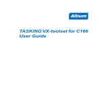
The 8051 assembler is part of a toolchain that provides an environment for
modular program development and debugging. The following figure
• • • • • • • •
Chapter 1
1−4
explains the relationship between the different parts of the TASKING 8051
toolchain:
C source file
.c
assembly source file
.asm
cc51
Compiler
mpp51
Macro Preprocessor
assembly file
.src
asm51
Assembler
List file .lst
relocatable object
module .obj
ar51
Librarian
object library
.lib
C−51 library
Linker command file
OMF51 relocatable
object file
OMF51 library
link51
Linker/Locator
List file .l51
OVERVIEW
absolute object
module a.out
ihex51
Formatter
ieee51
Formatter
omf51
Formatter
Intel Hex−records
IEEE−695 load module
Absolute OMF51 file
xfw51
CrossView Pro
Debugger
8051
execution
environment
Figure 1−1: 8051 development flow
Overview
1−5
1.2 ENVIRONMENT VARIABLES
This section contains an overview of the environment variables used by
the 8051 toolchain.
Environment
Variable
Description
ASMDIR
With this variable you specify one or more additional
directories in which the macro preprocessor mpp51
looks for include files.
CC51INC
With this variable you specify one or more additional
directories in which the C compiler cc51 looks for
include files. The compiler first looks in these
directories, then always looks in the default
include directory relative to the installation
directory.
CC51LIB
With this variable you specify one or more additional
directories in which the linker link51 looks for library
files.
LM_LICENSE_FILE
With this variable you specify the location of the
license data file. You only need to specify this
variable if the license file is not on its default location
(c:\flexlm for Windows,
/usr/local/flexlm/licenses for UNIX).
PATH
With this variable you specify the directory in which
the executables reside. This allows you to call the
executables when you are not in the bin directory.
Usually your system already uses the PATH variable
for other purposes. To keep these settings, you
need to add (rather than replace) the path. Use a
semicolon (;) to separate pathnames.
TASKING_LIC_WAIT
If you set this variable, the tool will wait for a license
to become available, if all licenses are taken. If you
have not set this variable, the tool aborts with an
error message. (Only useful with floating licenses)
TMPDIR
With this variable you specify the location where
programs can create temporary files. Usually your
system already uses this variable. In this case you
do not need to change it.
Table 1−1: Environment variables
• • • • • • • •
Chapter 1
1−6
1.3 TEMPORARY FILES
The assembler, linker, locator and archiver may create temporary files. By
default these files will be created in the current directory. If you want the
tools to create temporary files in another directory you can enforce this by
setting the environment variable TMPDIR.
PC:
set TMPDIR=c:\tmp
UNIX:
Bourne shell, Korn shell:
TMPDIR=\tmp ; export TMPDIR
csh:
setenv TMPDIR /tmp
Note that if you create your temporary files on a directory which is
accessible via the network for other users as well, conflicts in the names
chosen for the temporary files may arise. It is safer to create temporary
files in a directory that is solely accessible to yourself. Of course this does
not apply if you run the tools with several users on a multi−user system,
such as UNIX. Conflicts may arise if two different computer systems use
the same network directory for tools to create their temporary files.
OVERVIEW
1.4 FORMATTING A FILE FOR A DEBUGGER
Before a file generated by the linker can be loaded into a debugger it must
be in a suitable format. This format is known as IEEE−695. The 8051
Cross−Assembler package includes a utility program ieee51 which can
format output files into this IEEE format.
The simplest call of this program follows; for a full description of ieee51
see the chapter Utilities.
ieee51 opprog3 opprog3.abs
The output file opprog3.abs can now be loaded into a debugger.
Overview
1−7
1.5 FILE EXTENSIONS
The assembler accepts files with any extension (or even no extension), but
by adding the extension .src to assembler source files, you can
distinguish them easily.
Another reason for using the .src extension is that the assembler uses
this extension by default if it is omitted. So,
asm51 write
has the same effect as
asm51 write.src
Both these commands assemble the file write.src and create a list file
write.lst and a relocatable object module write.obj.
For compatibility with future TASKING Cross−Software the following
extensions are suggested:
.asm
.src
.obj
.lib
.out
.abs
.hex
.sre
.lst
.l51
input assembly source file for mpp51
output from the string macro preprocessor mpp51
or the C compiler / input for asm51
relocatable object files
object libraries files in archive format
relocatable output files from link51
absolute IEEE−695 output files
absolute Intel Hex output files
absolute Motorola S−record output files
assembler list file
linker list file
1.6 PREPROCESSING
For a description of the possibilities offered by the string macro
preprocessor see the chapter Macro Preprocessor. In this section we shall
merely show how it can be used in conjunction with the assembler.
The program write.src does not need to be preprocessed using
mpp51. We shall nevertheless use write.src file to demonstrate the use
of the macro preprocessor. First the file write.src is renamed to
write.asm.
• • • • • • • •
Chapter 1
1−8
The simplest call to mpp51 is:
mpp51 write.asm
The result of this command is that the file write.src will be created. The
contents of this file will be the same as write.asm.
1.7 ASSEMBLER LISTING
The assembler generates a listing file by default. As a result of the
command:
asm51 write.src
the listing file write.lst is created. If a listing is not desired the
NOPRINT control can be used. For example:
asm51 write.src NOPRINT
To redirect the listing information to another file the PRINT control is
available. For example:
asm51 write.src PRINT(list.lst)
asm51 is a three−pass assembler. The listing file is generated in the last
phase.
OVERVIEW
1.8 ERROR MESSAGES
Error messages from the cross−assembler are sent to the standard error
device and written in the list file. If severe errors occur in one of the first
two passes the error messages only occur on the standard error device
because the assembler aborts before the third pass. It may however be
useful to have a (not yet complete) list file of these first phases with the
error messages inserted on the place where they occurred. This can be
done using the LISTALL control.
If this control is specified the assembler creates a listing file in every
phase. If a phase ends successfully, the listing file will be overwritten in
the next phase.
Overview
1−9
1.9 SYMBOLIC DEBUGGING
To facilitate debugging, the programmer can decide how much symbolic
debugging information to include in the load file. The following categories
of information are available:
1. PUBLIC names
2. local names
3. compiler generated names
4. names defined in ?SYMB directives
5. records for ?LINE and ?FILE directives
6. segment names
7. version information
Each category is associated with one bit of a 7−bit pattern; for a full
description see the chapter Assembler Controls. By default all categories
except compiler generated names are included in the load file, which is
correct for user written assembly programs.
PL/M51 generated assembly source files contain the control DEBUGINFO(
0F9H ), which exports everything except compiler generated names and
assembler local symbols.
In the following example we shall use DEBUGINFO, requesting that all
possible information be generated.
asm51 write.src DEBUGINFO( 377O )
For more information, see the the debugging directives ?SYMB, ?LINE,
?FILE in the chapter Assembler Directives.
• • • • • • • •
OVERVIEW
1−10
Chapter 1
CHAPTER
2
MACRO
PREPROCESSOR
CHAPTER
MACRO PREPROCESSOR
2−2
Chapter 2
2
Macro Preprocessor
2.1 INTRODUCTION
The macro preprocessor, mpp51, is a string manipulation tool which
allows you to write repeatedly used sections of code once and then insert
that code at several places in your program. mpp51 also handles
conditional assembly, assembly−time loops, console I/O and recursion.
The macro preprocessor is implemented as a separate program which
saves both time and space in an assembler, particularly for those programs
that do not use macros and thus need not run the macro preprocessor.
mpp51 is compatible with Intel’s syntax for the 8051 macro processing
language (MPL). A user of macros must submit his source input to the
macro preprocessor. The macro preprocessor produces one output file
which can then be used as an input file to the 8051 Cross−assembler.
The macro preprocessor regards its input file as a stream of characters, not
as a sequence of statements like the assembler does. The macro
preprocessor scans the input (source) file looking for macro calls. A
macro−call is a request to the macro preprocessor to replace the call
pattern of a built−in or user−defined macro with its return value.
As soon as a macro call is encountered, the macro preprocessor expands
the call to its return value. The return value of a macro is the text that
replaces the macro call. This value is then placed in a temporary file, and
the macro preprocessor continues. The return value of some macros is the
null string, i.e., a character string containing no characters. So, when these
macros are called, the call is replaced by the null string on the output file,
and the assembler will never see any evidence of its presence. This is of
course particularly useful for conditional assembly.
This chapter documents mpp51 in several parts. First the invocation of
mpp51 is described. The following sections describe how to define and
use your own macros, describe the syntax of the macro processing
language and describe the macro preprocessor’s built−in functions. This
chapter also contains a section that is devoted to the advanced concepts of
mpp51.
The first five sections give enough information to begin using the macro
preprocessor. However, sometimes a more exact understanding of
mpp51’s operation is needed. The advanced concepts section should fill
those needs.
• • • • • • • •
2−3
Chapter 2
2−4
At macro time, symbols, labels, predefined assembler symbols, EQU, and
SET symbols, and the location counter are not known. The macro
preprocessor does not recognize the assembly language. Similarly, at
assembly time, no information about macro symbols is known.
2.2 MPP51 INVOCATION
The command line invocation line of mpp51 is:
MACRO PREPROCESSOR
mpp51 [option]... input−file [output−file]
mpp51 −V
mpp51 −?
When you use a UNIX shell (C−shell, Bourne shell), arguments
containing special characters (such as ’( )’ ) must be enclosed with " ".
The invocations for UNIX and PC are the same, except for the −? option in
the C−shell:
mpp51 "−?"
or
mpp51 −\?
The input−file is an assembly source file containing user−defined macros.
You must give a complete filename (no default file extension is taken).
The output−file is an assembly source file in which all user−defined macros
are replaced. This file is the input file for asm51. If output−file is omitted,
the output file has the same basename as the input file but with the file
extension .src.
Invocation with −V only displays a version header.
Macro Preprocessor
2−5
Option
Description
−?
Display invocation syntax
−Dmacro=def
Define preprocessor macro
−f file
Read options from file
−Idirectory
Look in directory for include files
−Umacro
Undefine preprocessor macro
−V
Display version header only
−ofilename
Specify name of output file
−−[no−]allow−undefined−macro
Allow expansion of undefined macros
−−disable=nr[,nr]...
Suppress a warning and/or error
−−[no−]file−info
Generate source file line info
−−[no−]info−messages
Generate info messages
−−max−nesting=value
Set the maximum include file nesting level
(default=31)
−−[no−]parameters−redefine
Allow macro parameters to be redefined
−−[no−]prompt=string
Set the prompt for the %IN command
−−[no−]skip−asm−comment
Skip parsing after assembly comment ’;’
−−[no−]warn−on−undefined−
macro
Warn on expansion of undefined macros
Table 2−1: mpp51 options
2.2.1 DETAILED DESCRIPTION OF MACRO
PREPROCESSOR OPTIONS
With options that can be set from within EDE, you will find a mouse icon
that describes the corresponding action.
• • • • • • • •
Chapter 2
2−6
−?
Option:
−?
Description:
Display an explanation of options at stdout.
Example:
MACRO PREPROCESSOR
mpp51
−?
Macro Preprocessor
−−allow−undefined−macro
Option:
From the Project menu, select Project Options... Expand the Assembler
entry and select Macro Preprocessor. Add the option to the Additional
macro preprocessor options field.
−−allow−undefined−macro
−−no−allow−undefined−macro
Default:
−−no−allow−undefined−macro
Description:
With this option the macro preprocessor will not issue an error when it
finds an undefined macro.
Example:
mpp51 −−allow−undefined−macro test.asm
• • • • • • • •
2−7
Chapter 2
2−8
−D
Option:
From the Project menu, select Project Options... Expand the Assembler
entry and select Macro Preprocessor. Define a macro (syntax:
macro[=def]) in the Define user macros field. You can specify and define
more macros by separating them with commas.
−Dmacro=[def]
Arguments:
The macro you want to define and optionally its definition.
MACRO PREPROCESSOR
Description:
Define macro as in ’define’. Any number of symbols can be defined. If
def is not given, the symbol is defined to the null string.
Example:
The following command defines symbol LEVEL to 3:
mpp51 −DLEVEL=3 test.asm
The following command defines symbol LEVEL to the null string:
mpp51 −DLEVEL= test.asm
Macro Preprocessor
−−disable
Option:
From the Project menu, select Project Options... Expand the Assembler
entry and select Macro Preprocessor. Add the option to the Additional
macro preprocessor options field.
−−disable=number[,number]...
Description:
With this option you can suppress one or more errors or warnings.
Example:
To suppress errors 115 and 116, enter:
mpp51 −−disable=115,116 test.asm
• • • • • • • •
2−9
Chapter 2
2−10
−f
Option:
From the Project menu, select Project Options... Expand the Assembler
entry and select Macro Preprocessor. Add the option to the Additional
macro preprocessor options field.
−f file
Arguments:
A filename for command line processing. The filename "−" may be used to
denote standard input.
MACRO PREPROCESSOR
Description:
Use file for command line processing. To get around the limits on the size
of the command line, it is possible to use command files. These command
files contain the options that could not be part of the real command line.
Command files can also be generated on the fly, for example by the make
utility.
More than one −f option is allowed.
Some simple rules apply to the format of the command file:
1. It is possible to have multiple arguments on the same line in the command
file.
2. To include whitespace in the argument, surround the argument with either
single or double quotes.
3. If single or double quotes are to be used inside a quoted argument, we
have to go by the following rules:
a. If the embedded quotes are only single or double quotes, use the
opposite quote around the argument. Thus, if a argument should
contain a double quote, surround the argument with single quotes.
b. If both types of quotes are used, we have to split the argument in such
a way that each embedded quote is surrounded by the opposite type
of quote.
Macro Preprocessor
Example:
"This has a single quote ’ embedded"
or
’This has a double quote " embedded’
or
’This has a double quote " and \
a single quote ’"’ embedded"
4. Some operating systems impose limits on the length of lines within a text
file. To circumvent this limitation it is possible to use continuation lines.
These lines end with a backslash and newline. In a quoted argument,
continuation lines will be appended without stripping any whitespace on
the next line. For non−quoted arguments, all whitespace on the next line
will be stripped.
Example:
"This is a continuation \
line"
−> "This is a continuation line"
control(file1(mode,type),\
file2(type))
−>
control(file1(mode,type),file2(type))
5. It is possible to nest command line files up to 25 levels.
Example:
Suppose the file mycmds contains the following line:
−DLEVEL=3
test.asm
The command line can now be:
mpp51 −f mycmds
• • • • • • • •
2−11
Chapter 2
2−12
−−file−info
Option:
From the Project menu, select Project Options... Expand the Assembler
entry and select Macro Preprocessor. Add the option to the Additional
macro preprocessor options field.
−−file−info
−−no−file−info
Default:
−−file−info
MACRO PREPROCESSOR
Description:
By default, the macro preprocessor generates source file line information,
such as:
# 1 "<path>/test.asm"
With option −−no−file−info the macro preprocessor does not generate
this information.
Example:
mpp51 −−no−file−info test.asm
Macro Preprocessor
−I
Option:
From the Project menu, select Directories... Add one or more directory
paths to the Include Files Path field.
−Idirectory
Arguments:
The name of the directory to search for include file(s).
Description:
Change the algorithm for searching $INCLUDE files whose names do not
have an absolute pathname to look in directory. Thus, $INCLUDE files are
searched for first in the directory of the file containing the $INCLUDE line,
then in directories named in −I options in left−to−right order. If the files
are still not found mpp51 checks if the environment variable ASMDIR
exists. If it does, it searches the directories specified in ASMDIR. More than
one directory can be specified to ASMDIR by separating the directories
with a semi−colon ’;’.
Example:
mpp51 −I/proj/include test.asm
Section Include Files
• • • • • • • •
2−13
Chapter 2
2−14
−−info−messages
Option:
From the Project menu, select Project Options... Expand the Assembler
entry and select Macro Preprocessor. Add the option to the Additional
macro preprocessor options field.
−−info−messages
−−no−info−messages
Default:
−−info−messages
MACRO PREPROCESSOR
Description:
By default, the macro preprocessor can generate informational messages in
addition to errors or warnings. With option −−no−info−messages the
macro preprocessor does not generate informational messages.
Example:
mpp51 −−no−info−messages test.asm
Macro Preprocessor
−−max−nesting
Option:
From the Project menu, select Project Options... Expand the Assembler
entry and select Macro Preprocessor. Add the option to the Additional
macro preprocessor options field.
−−max−nesting=number
Default:
31
Description:
With this option you can set the maximum include file nesting level.
Example:
To set the maximum include file nesting level to 50, enter:
mpp51 −−max−nesting=50 test.asm
• • • • • • • •
2−15
Chapter 2
2−16
−−parameters−redefine
Option:
From the Project menu, select Project Options... Expand the Assembler
entry and select Macro Preprocessor. Add the option to the Additional
macro preprocessor options field.
−−parameters−redefine
−−no−parameters−redefine
Default:
−−no−parameters−redefine
MACRO PREPROCESSOR
Description:
With option −−parameters−redefine it is allowed to use the %SET macro
to redefine a macro parameter.
Example:
mpp51 −−parameters−redefine test.asm
Macro Preprocessor
−−prompt
Option:
From the Project menu, select Project Options... Expand the Assembler
entry and select Macro Preprocessor. Add the option to the Additional
macro preprocessor options field.
−−prompt=string
Default:
>
Description:
With this option you can set the prompt for the %IN built−in function.
Example:
To set the prompt for the %IN function to "cmd>", enter:
mpp51 −−prompt="cmd>" test.asm
• • • • • • • •
2−17
Chapter 2
2−18
−o
Option:
EDE determines the name of the output file with the same basename as
the input file and extension .src..
−ofilename
Arguments:
An output filename.
Default:
MACRO PREPROCESSOR
Basename of input file with .src suffix.
Description:
Use filename as output filename of the macro preprocessor, instead of the
basename of the input file with the .src extension.
Example:
To create the assembly file myfile.src instead of test.src, enter:
mpp51 test.asm −omyfile.src
Macro Preprocessor
−−skip−asm−comment
Option:
From the Project menu, select Project Options... Expand the Assembler
entry and select Macro Preprocessor. Add the option to the Additional
macro preprocessor options field.
−−skip−asm−comment
−−no−skip−asm−comment
Default:
−−no−skip−asm−comment
Description:
With option −−skip−asm−comment the macro preprocessor skips
parsing after assembly comment ’;’. By default, comment is also parsed.
Example:
mpp51 −−skip−asm−comment test.asm
• • • • • • • •
2−19
Chapter 2
2−20
−U
Option:
From the Project menu, select Project Options...
Expand the Assembler entry and select Macro Preprocessor. Remove
definitions from the Define user macros field or add the option −U to the
Additional macro preprocessor options field.
−Umacro
Arguments:
The macro you want to undefine.
MACRO PREPROCESSOR
Description:
With this option you can undefine a previously defined symbol.
Example:
The following command undefines symbol LEVEL:
mpp51 −ULEVEL test.asm
Macro Preprocessor
2−21
−V
Option:
−V
Description:
With this option you can display the version header of the macro
preprocessor. This option must be the only argument of mpp51. Other
options are ignored. mpp51 exits after displaying the version header.
Example:
mpp51 −V
TASKING 8051 macro preprocessor
Copyright years Altium BV
• • • • • • • •
vx.yrz Build nnn
Serial# 00000000
Chapter 2
2−22
−−warn−on−undefined−macro
Option:
From the Project menu, select Project Options... Expand the Assembler
entry and select Macro Preprocessor. Add the option to the Additional
macro preprocessor options field.
−−warn−on−undefined−macro
−−no−warn−on−undefined−macro
Default:
−−no−warn−on−undefined−macro
MACRO PREPROCESSOR
Description:
With option −−warn−on−undefined−macro the macro preprocessor
generates warning W 201 instead of error E 301 when an undefined macro
name is found.
Example:
mpp51 −−warn−on−undefined−macro test.asm
Macro Preprocessor
2.3 INCLUDE FILES
If the macro preprocessor encounters a $INCLUDE statement in the input
file, preprocessing will continue by scanning the specified file until an
end−of−file or another INCLUDE is encountered.
Syntax:
$INCLUDE(file)
Abbreviation:
$IC(file)
Expansion:
$<spaces><eol># 1 "file"
Description:
The ’$’ must be in column 1 for the macro preprocessor to recognize it for
processing at macro time. In the output file the INCLUDE(file) part of the
INCLUDE call is replaced by spaces (because the assembler also
recognizes the ’$’ character but does not recognize INCLUDE as a control).
Also a line containing # 1 "file" is put in the output file.
As soon as the macro preprocessor encounters an end−of−file in the
include file, input is resumed where it left off, namely at the next line after
the latest INCLUDE call (which due to nesting does not necessarily mean
returning to the original input file). Nesting of include files is allowed up
to 32 files.
If the macro preprocessor after recognizing the ’$’ character does not find
an INCLUDE before it encounters an end−of−line, due to misspelling or
simple because the ’$’ is followed by a control only recognized by the
assembler, no macro−time error is reported and scanned characters are
simply passed to the output file.
mpp51 first searches for $INCLUDE files in the directory of the file
containing the $INCLUDE line, then in directories named in −I options in
left−to−right order. If the files are still not found mpp51 checks if the
environment variable ASMDIR exists. If it does, it searches the directories
specified in ASMDIR. More than one directory can be specified to ASMDIR
by separating the directories with a semi−colon ’;’.
• • • • • • • •
2−23
Chapter 2
2−24
Restriction:
Each control line (i.e. a line starting with ’$’) may not contain more than
one INCLUDE call.
Example:
; source lines
.
$include( mysrc.inc )
; include the contents of
; file mysrc.inc
.
; other source lines
.
MACRO PREPROCESSOR
2.4 CREATING AND CALLING MACROS
Macro calls differ between user−defined macros and so−called built−in
functions. All characters in bold typeface in the syntax descriptions of the
following sections are constituents of the macro syntax. Italic tokens
represent place holders for user−specific declarations.
The macro preprocessor scans through the input source, one character at a
time, looking for a special character called the METACHARACTER, the
percent sign ’%’ initially. This metacharacter must precede a macro−call.
Until the macro preprocessor finds a metacharacter, it does not process
text. It simply passes the text from the input file to the output file.
Since mpp51 only processes macro calls, it is necessary to call a macro in
order to create other macros, the so−called "user−defined macros". The
built−in function DEFINE creates macros. Built−in functions are a
predefined part of the macro language, so they may be called without
prior definition. The general syntax for DEFINE is shown below.
Syntax:
%[*]DEFINE (macro−name[parameter−list]) [LOCAL local−list]
(macro−body)
DEFINE is the most important mpp51 built−in function. This section is
devoted to describing this built−in function. Each of the symbols in the
syntax above (macro−name, parameter−list, local−list and macro−body)
are described in detail on the pages that follow. In some cases, we have
abbreviated this general syntax to emphasize certain concepts.
Macro Preprocessor
2.4.1
CREATING PARAMETERLESS MACROS
When you create a parameterless macro, there are two parts to a DEFINE
call: the macro−name and the macro−body. The macro−name defines the
name used when the macro is called; the macro−body defines the return
value of the call.
Syntax:
%[*]DEFINE (macro−name) (macro−body)
The ’%’ character signals a macro call. The ’*’ is the optional literal
character. When you define a macro using the literal character ’*’, as
shown above, macro calls contained in the body of the macro are not
expanded until the macro is called. The exact use of the literal character is
discussed in the advanced concept section. When you define a
parameterless macro, the macro−name is a macro identifier that follows
the ’%’ character in the source line. The rules for macro identifier are:
− The identifier must begin with an upper or lowercase alphabetic
character (A,B,...,Z or a,b,...,z), or a special character ( a question
mark ’?’ or an underscore character ’_’).
− The remaining characters may be alphabetic, special or decimal
digits (0,1,2,...,9).
− Only the first 31 characters of a macro identifier are recognized as
the unique identifier name. Upper and lower case characters are not
distinguished in a macro identifier.
The macro−body is usually the return value of the macro call. However,
the macro−body may contain calls to other macros. If so, the return value
is actually the fully expanded macro−body, including the return values of
the call to other macros. The macro call is re−expanded each time it is
called.
• • • • • • • •
2−25
Chapter 2
2−26
Example 1:
%*DEFINE (String_1)
(An)
%*DEFINE (String_2)
(ele)
%*DEFINE (String_3)
(phant)
%*DEFINE (String_4)
(shopping)
%DEFINE (String_5)
%String_4)
(goes
MACRO PREPROCESSOR
%DEFINE (Part_1)
(%String_1 %String_2%String_3)
The macro−body must consist of a balanced−text string, i.e. you must
have balanced parentheses within the macro−body. In other words, each
left parenthesis must have a succeeding right parenthesis, and each right
parenthesis must have a preceding left parenthesis.
The possible placement of the macro−body and the parenthesis are both
represented in the above examples. The beginning of the macro−body is
determined by the syntactical end of the left parenthesis, where tabs
(08H), blanks and the first new line (0AH) are also part of the
macro−body.
The macro−body of String_1 starts with the ’A’ of "An"
The macro−body of String_3 starts with the ’p’ of "phant"
The macro−body of String_4 starts with the ’(08H)’ of "(08H)shopping".
The end of macro−body is determined by the right parenthesis.
The macro−body of String_4 is
The macro−body of String_5 is
"(08H)shopping"
"goes (0AH)
(08H)shopping"
The expanded value of DEFINE is the null string, but the macro body is
stored internally for later use. User−defined macros may invoke themselves
within their bodies. This property is called ’recursion’. Any macro which
calls itself must terminate eventually or the macro preprocessor may enter
an infinite loop.
Once a macro has been created, it may be redefined by a second call to
DEFINE.
Macro Preprocessor
2−27
To call a macro, you use the ’%’ character followed by the name of the
macro (the literal character ’*’ is only admissible for defined macros whose
call is passed to a macro as a an actual parameter; example: %M1(%*M2)).
The macro preprocessor removes the call and inserts the return value of
the call. If the macro−body contains any call to other macros, they are
replaced with their return values.
Example 2:
%Part_1 %String_5
−−>
An elephant goes
shopping
Once a macro has been created, it may be redefined by a second call to
DEFINE. Note, however that a macro should not redefine itself within its
body (see Advanced mpp51 Concepts).
The examples below show several macro definitions. Their return values
are also shown.
Example 3:
Macro definition at the top of the program:
%*DEFINE (MOVE)
(
MOV A, @R1
MOV @R2, A
)
The macro call as it appears in the program:
MOV R1, #1
−−−−%MOVE
The program as it appears after the macro preprocessor made the
following expansion, where the first expanded line is preceded by the four
blanks preceding the call (the sign − indicates the preceding blanks):
MOV
−−−−
• • • • • • • •
R1, #1
MOV A, @R1
MOV @R2, A
Chapter 2
2−28
Example 4:
Macro definition at the top of the program:
%*DEFINE (ADD5)
(
MOV R0, #5
MOV R5, @R2
ADD R5, R0
)
The macro call as it appears in the original program body:
MOV
R5, #2
%ADD5
MACRO PREPROCESSOR
The program after the macro expansion:
MOV
MOV
MOV
ADD
R5,
R0,
R5,
R5,
#2
#5
@R2
R0
Example 5:
Macro definition at the top of the program:
%*DEFINE (MOVE_AND_ADD) (
%MOVE
%ADD5
)
The macro call as it appears in the body of the program:
MOV R1, #1
%MOVE_AND_ADD
The program after the macro expansion:
MOV
R1, #1
MOV
MOV
A, @R1
@R2, A
MOV
MOV
ADD
R0, #5
R5, @R2
R5, R0
Macro Preprocessor
2.4.2
CREATING MACROS WITH PARAMETERS
If the only function of the macro preprocessor was to perform simple
string replacement, then it would not be very useful for most of the
programming tasks. Each time we wanted to change even the simplest part
of the macro’s return value we would have to redefine the macro.
Parameters in macro calls allow more general−purpose macros. Parameters
leave holes in a macro−body that are filled in when you call the macro.
This permits you to design a single macro that produces code for typical
programming operations. The term ’parameters’ refers to both the formal
parameters that are specified when the macro is defined (the holes, and
the actual parameters or arguments that are specified when the macro is
called (the fill−ins).
The syntax for defining macros with parameters is very similar to the
syntax for macros without parameters.
Syntax:
%[*]DEFINE (macro−name[parameter−list]) (macro−body)
The macro−name must be a valid identifier.
The parameter−list is a list of macro identifiers separated by macro
delimiters. These identifiers comprise the formal parameters used in the
macro. The macro identifier for each parameter in the list must be unique,
but they may be the same as other formal argument names to other
macros since they have no existence outside the macro definition. They
may also be the same as the names of other user macros or of macro
functions. Note, however that in this case the macro or function cannot be
used within the macro−body, since its name would be recognized as a
parameter instead. To reference a formal argument within the macro−body,
use its name preceded by the metacharacter.
Typically, the macro delimiters are parentheses and commas. When using
these delimiters, you would enclose the parameter−list in parentheses and
separate each formal parameter with a comma. When you define a macro
using parentheses and commas as delimiters, you must use those same
delimiters, when you call that macro.
The example below shows the definition of a macro with three
parameters: SOURCE, DEST and COUNT. The macro produces code to copy
any number of words from one part of memory to another.
• • • • • • • •
2−29
Chapter 2
2−30
Example:
%*DEFINE (MOVE_ADD_GEN(SOURCE,DEST,COUNT))
(
MOV R1, #%SOURCE
MOV R0, #%DEST
MOV R7, #%COUNT
MOV A, @R1
MOV @R0, A
INC R1
INC R0
DJNZ R7, ($−4)
)
MACRO PREPROCESSOR
To call a macro with parameters, you must use the metacharacter followed
by the macro’s name as with parameterless macros. However, a list of the
actual parameters must follow. These actual parameters have to be
enclosed within parentheses and separated from each other by commas.
The actual parameters may optionally contain calls to other macros.
A simple call to a macro defined above might be:
%MOVE_ADD_GEN( 10, 24, 8 )
The above macro call produces the following code:
MOV
MOV
MOV
MOV
MOV
INC
INC
DJNZ
R1, #10
R0, #24
R7, #8
A, @R1
@R0, A
R1
R0
R7, ($−4)
Macro Preprocessor
2.4.3
LOCAL SYMBOLS IN MACROS
If we used a fixed label instead of the offset ($−4) in the previous
example, the macro using the fixed label can only be called once, since a
second call to the macro causes a conflict in the label definitions at
assembly time. The label can be made a parameter and a different symbol
name can be specified each time the macro is called.
A preferable way to ensure a unique label for each macro call is to put the
label in a local−list. The local−list construct allows you to use macro
identifiers to specify assembly−time symbols. Each use of a LOCAL symbol
in a macro guarantees that the symbol will be replaced by a unique
assembly−time symbol each time the symbol is called.
The macro preprocessor increments a counter once for each symbol used
in the list every time your program calls a macro that uses the LOCAL
construct. Symbols in the local−list, when used in the macro−body, receive
a two to five digit suffix that is the hexadecimal value of the counter. The
first time you call a macro that uses the LOCAL construct, the suffix is ’00’.
The syntax for the LOCAL construct in the DEFINE function is shown
below. (This is the complete syntax for the built−in function DEFINE):
Syntax:
%[*]DEFINE (macro−name[parameter−list]) [LOCAL local−list]
(macro−body)
The local−list is a list of valid macro identifiers separated by spaces. Since
these macro identifiers are not parameters, the LOCAL construct in a macro
has no effect on a macro call.
To reference local symbols in the macro−body, they must be preceded by
the metacharacter. The symbol LOCAL is not reserved; a user symbol or
macro may have this name.
The next example shows a macro definition that uses a LOCAL list.
• • • • • • • •
2−31
Chapter 2
2−32
Example:
%*DEFINE (MOVE_ADD_GEN(SOURCE,DEST,COUNT)) LOCAL LAB
(
MOV R1, #%SOURCE
MOV R0, #%DEST
MOV R7, #%COUNT
%LAB:
MOV A, @R1
MOV @R0, A
INC R1
INC R0
DJNZ R7, %LAB
)
A simple call to a macro defined above might be:
MACRO PREPROCESSOR
%MOVE_ADD_GEN( 50, 100, 24 )
The above macro call might produce the following code (if this is he
eleventh call to a macro using a LOCAL list):
MOV
MOV
MOV
LAB0A:
MOV
MOV
INC
INC
DJNZ
R1, #50
R0, #100
R7, #24
A, @R1
@R0, A
R1
R0
R7, LAB0A
Since macro identifiers follow the same rules as ASM51, any macro
identifier can be used in a local−list. However, if long identifier names are
used, they should be restricted to 29 characters. Otherwise, the label suffix
may cause the identifier to exceed 31 characters and these would be
truncated.
Macro Preprocessor
2−33
2.5 THE MACRO PREPROCESSOR’S BUILT−IN
FUNCTIONS
The macro preprocessor has several built−in or predefined macro
functions. These built−in functions perform many useful operations that
are difficult or impossible to produce in a user−defined macro.
We have already discussed one of these built−in functions, DEFINE.
DEFINE creates user−defined macros. DEFINE does this by adding an entry
in the macro preprocessor’s tables of macro definitions. Each entry in the
tables includes the macro−name of the macro, its parameter−list, its
local−list and its macro−body. Entries for the built−in functions are present
when the macro preprocessor begins operation.
Other built−in functions perform numerical and logical expression
evaluation, affect control flow of the macro preprocessor, manipulate
character strings, and perform console I/O.
The following sections deal with the following:
Comment, escape, bracket, group
Metachar function
(’...’, ’..., n..., (...), {...} )
(METACHAR)
Expressions processed by mpp51
Calculating functions
(SET, EVAL)
Undefine function
(UNDEF)
Controlling functions
(IF, IFDEF/IFNDEF, WHILE, REPEAT, EXIT)
String−processing functions
(LEN, SUBSTR, MATCH)
String−comparing functions
(EQS, NES, LTS, LES, GTS, GES)
Message functions
(ERROR, FATAL)
File/line info functions
(__FILE__, __LINE__)
Option function
(OPTION)
Input/Output functions
(IN, OUT)
• • • • • • • •
Chapter 2
2−34
2.5.1 COMMENT, ESCAPE, BRACKET AND GROUP
FUNCTIONS
2.5.1.1 COMMENT FUNCTION
The macro processing language can be very subtle, and the operation of
macros written in a straightforward manner may not be immediately
obvious. Therefore, it is often necessary to comment macro definitions.
Syntax:
%’text’
or
MACRO PREPROCESSOR
%’text end−of−line
The comment function always evaluates to the null string. Two terminating
characters are recognized: the apostrophe ’ and the end−of−line (line−feed
character, ASCII 0AH). The second form of the call allows macro
definitions to be spread over several lines, while avoiding any unwanted
end−of−lines in the return value. In either form of the comment function,
the text or comment is not evaluated for macro calls.
The literal character ’*’ is not accepted in connection with this function.
Example:
%*DEFINE (MOVE_ADD_GEN(SOURCE,DEST,COUNT)) LOCAL LAB
(
MOV R1, #%SOURCE %’This is the source address’
MOV R0, #%DEST %’This is the destination’
MOV R7, #%COUNT %’%COUNT must be a constant’
%LAB:
%’This is a local label.
%’End of line is inside the comment!
MOV A, @R1
MOV @R0, A
INC R1
INC R0
DJNZ R7, %LAB
)
Call the above macro:
%MOVE_ADD_GEN( 50, 100, 24 )
Macro Preprocessor
2−35
Return value from above call:
MOV
MOV
MOV
LAB0A:
MOV
MOV
INC
INC
DJNZ
R1, #50
R0, #100
R7, #24
A, @R1
@R0, A
R1
R0
R7, LAB0A
Note that the comments that were terminated with the end−of−line
removed the end−of−line character along with the rest of the comment.
The metacharacter is not recognized as flagging a call to the macro
preprocessor when it appears in the comment function.
2.5.1.2 ESCAPE FUNCTION
Sometimes it is necessary to prevent the macro preprocessor from
processing text. The escape function and the bracket function perform
such tasks.
Syntax:
%n text−of−n−characters−long
The escape function prevents the macro preprocessor from processing a
text string of n characters long, where n is a decimal digit from 0 to 9. The
escape function is useful for inserting a metacharacter as text, adding a
comma as part of an argument, or placing a single parenthesis in a
character string that requires balanced parentheses.
The literal character ’*’ is not accepted in connection with this function.
• • • • • • • •
Chapter 2
2−36
Example:
Before Macro Expansion After Macro Expansion
;Average of 20%1%
−>;Average of 20%
%DTCALL(JAN 21%1, 1992,
JUN 12%1, 1992)
−> JAN 21, 1992
−> JUN 12, 1992
%MYCALL(1%1) Option 1,
2%1) Option 2,
3%1) Option 2)
−> 1) Option 1
−> 2) Option 2
−> 3) Option 3
MACRO PREPROCESSOR
The first example add a literal ’%’ in the text. The second example keeps
the date as one actual parameter adding a literal ’,’. The third example
adds a literal right parenthesis ’)’ to each parameter.
2.5.1.3 BRACKET FUNCTION
The bracket function is the other built−in function that prevents the macro
preprocessor from expanding text.
Syntax:
%(balanced−text)
The bracket function prevents all macro preprocessor expansion of the
text contained within the parentheses. However, the escape function, the
comment function, and the parameter substitution are still recognized.
Since there is no restriction for the length of the text within the bracket
function, it is usually easier to use than the escape function.
The literal character ’*’ is not accepted in connection with this function.
Example:
%*DEFINE (DW(LIST,NAME))
(
%NAME DW %LIST)
The macro DW expands DW statements, where the variable NAME
represents the first parameter and the expression LIST represents the
second parameter.
The following expansion should be obtained by the call:
PHONE DW 198H, 3DH, 0F0H
Macro Preprocessor
If the call in the following form:
%DW(198H, 3DH, 0F0H, PHONE)
occurs, the macro preprocessor would interpret the first argument (198H)
as NAME and everything after the first comma as the second parameter,
since the first comma would be interpreted as the delimiter separating the
macro parameters.
In order to change this method of interpretation, all tokens that are to be
combined for an individual parameter must be identified as a parameter
string and set in a bracket function:
%DW(%(198H, 3DH, 0F0H), PHONE)
This way the bracket function prevents the string ’198H, 3DH, 0F0H’ from
being evaluated as separate parameters.
2.5.1.4 GROUP FUNCTION
The group function does the opposite of the bracket function, it ensures
that the text is expanded.
Syntax:
%{balanced−text}
The contents of the group macro is expanded and the resulting string is
then interpreted itselve like a macro command. This allows for definition
of complex recursive macros. Another useful application of the group
command is to separate macro identifiers from surrounding, possible valid
identifier characters.
The literal character ’*’ is not accepted in connection with this function.
Example:
%define(TEXTA)(Text A)
%define(TEXTB)(Text B)
%define(TEXTC)(Text C)
%define(SELECT)(B)
%{TEXT%SELECT}
• • • • • • • •
2−37
Chapter 2
2−38
The contents of the group function, TEXT%SELECT, expands to TEXTB,
which on its turn is expanded like %TEXTB resulting in Text B.
Example:
%define(op)(add)
%{op}_and_move
The group function ensures that the macro op is expanded. Without it,
op_and_move would be seen as the macro identifier.
2.5.2
METACHAR FUNCTION
MACRO PREPROCESSOR
The METACHAR function can be used to redefine the metacharacter
(initially: ’%’)
Syntax:
%METACHAR(balanced−text)
Although the balanced−text string may be any number of characters long,
only the first character in the string is taken to be the new metacharacter.
Macro calls in the balanced−text string are still recognized and
corresponding actions that will not lead to any direct expansion on the
output file will be performed. So, for example a SET macro call inside the
balanced−text string will be performed.
Characters that may not be used as a metacharacter are: a blank, letter,
digit, left or right parenthesis, or asterisk.
The following example is catastrophic !!!
%METACHAR( & )
This examples defines the space character as the new metacharacter, since
it is the first character in the balanced−text strings!
Macro Preprocessor
2.5.3
2−39
NUMBERS AND EXPRESSIONS IN MPP51
Many built−in functions recognize and evaluate numerical expressions in
their arguments. mpp51 uses the same rules for representing numbers as
asm51 (see chapter Operands And Expressions for detailed information):
− Numbers may be represented in the formats binary (B suffix), octal
(O or Q suffix), decimal (D or no suffix), and hexadecimal (H
suffix).
− Internal representation of numbers is 16−bits (00H to 0FFFFH); the
processor does not recognize or output real or long integer
numbers.
− The following operators are recognized by the macro preprocessor
(in descending precedence):
1.
2.
3.
4.
5.
6.
7.
8.
’(’
LOW
’*’
’+’
EQ
NOT
AND
OR
’)’
HIGH
’/’
’−’
NE
MOD
SHL
(both binary and unary)
LE
LT
SHR
GE
GT
XOR
The symbolic forms of the relational operators (i.e., <, >, =, <>, >=, <=) are
not recognized by the macro preprocessor.
The macro preprocessor cannot access the assembler’s symbol table. The
values of labels, location counter, EQU and SET symbols are not known
during macro time expression evaluation. Any attempt to use assembly
time symbols in a macro time expression generates an error. Macro time
symbols can be defined, however, with the predefined macro, SET.
• • • • • • • •
Chapter 2
2−40
2.5.4
SET FUNCTION
SET assigns the value of the numeric expression to the identifier,
macro−variable, and stores the macro−variable in the macro time symbol
table, macro−variable must follow the same syntax convention used for
other macro identifiers. Expansion of a macro−variable always results in
hexadecimal format.
Syntax:
MACRO PREPROCESSOR
%SET (macro−variable,expression)
The SET macro call affects the macro time symbol table only; when SET is
encountered, the macro preprocessor replaces it with the null string.
Symbols defined by SET can be redefined by a second SET call, or defined
as a macro by a DEFINE call The SET function is thanks to the necessary
compatibility with Intel the only predefined macro function which may be
redefined. Such a redefinition of the SET function must however be
strongly dissuaded, because as a consequence, the original functionality
will be lost for the rest of the program, i.e., macro−time symbols can no
longer be defined.
Example:
%SET(COUNT,0)
%SET(OFFSET,16)
MOV R1, #%COUNT + %OFFSET
MOV R2, #%COUNT
−>
−>
−>
−>
null string
null string
MOV R1,#0H + 10H
MOV R2,#0H
SET can also be used to redefine symbols in the macro time table:
%SET(COUNT,%COUNT + %OFFSET)
%SET(OFFSET,%OFFSET * 2)
MOV R1, #%COUNT + %OFFSET
MOV R2, #%COUNT
−>
−>
−>
−>
null string
null string
MOV R1,#10H + 20H
MOV R2,#10H
Macro Preprocessor
2.5.5
2−41
EVAL FUNCTION
The built−in function EVAL accepts an expression as its argument and
returns the expression’s value in hexadecimal.
Syntax:
%EVAL( expression )
The expression argument must be a legal macro−time expression. The
return value from EVAL is built according to asm51’s rules for representing
hexadecimal numbers. The trailing character is always the hexadecimal
suffix (H). The expanded value is at most 16 bits and negative numbers
are shown in two’s complement form. If the leading digit of the
return−value is ’A’, ’B’, ’C’, ’D’, ’E’ or ’F’, it is preceded by a 0.
Example:
COUNT SET %EVAL(33H + 15H + 0f00H)
MOV
R1, #%EVAL(10H − ((13+6) *2 ) +7)
%SET( NUM1, 44)
%SET( NUM2, 25)
MOV
−> MOV
R1, #0fff1H
−> null string
−> null string
R1, #%EVAL( %NUM1 LE %NUM2 )
2.5.6
−> COUNT SET 0f48H
−> MOV
R1, #00H
UNDEF FUNCTION
The built−in function UNDEF can be used to undefine a previously
defined macro, and also to undefine one of the predefined macro
functions.
Syntax:
%UNDEF(identifier)
The identifier must be a previously defined macro name or one of the
built−in functions. The UNDEF command is replaced with the null string.
Example:
%DEFINE(TEMP)(path)
−> macro TEMP is defined
%UNDEF(TEMP)
%UNDEF(SET)
%SET(COUNT,0)
−> null string, TEMP is undefined
−> null string
−> undefined macro name: SET
• • • • • • • •
Chapter 2
2−42
2.5.7 LOGICAL EXPRESSIONS AND STRING
COMPARISONS IN MPP51
Several built−in functions return a logical value when they are called. Like
relational operators that compare numbers and return TRUE or FALSE
(’0fffH’ or ’00H’) respectively, these built−in functions compare character
strings. If the function evaluates to ’TRUE’, then it returns the character
string ’0ffffH’. If the function evaluates to ’FALSE’, then it returns ’00H’.
MACRO PREPROCESSOR
The built−in functions that return a logical value compare two
balanced−text arguments and return a logical value based on that
comparison. The list of string comparison functions below shows the
syntax and describes the type of comparison made for each. Both
arguments may contain macro calls.
%EQS(arg1,arg2)
TRUE if both arguments are identical; equal
%NES(arg1,arg2)
TRUE if arguments are different in any way;
not equal
%LTS(arg1,arg2)
TRUE if first argument has a lower value
than second argument; less than
%LES(arg1,arg2)
TRUE if first argument has a lower value
than second argument or if both arguments
are identical; less than or equal
%GTS(arg1,arg2)
TRUE if first argument has a higher value
than second argument; greater than
%GES(arg1,arg2)
TRUE if first argument has a higher value
than second argument, or if both arguments
are identical; greater than or equal
Before these functions perform a comparison, both strings are completely
expanded. Then the ASCII value of the first character in the first string is
compared to the ASCII value of the first character in the second string. If
they differ, then the string with the higher ASCII value is to be considered
to be greater. If the first characters are the same, the process continues
with the second character in each string, and so on. Only two strings of
equal length that contain the same characters in the same order are equal.
Macro Preprocessor
2−43
Example:
Before Macro Expansion After Macro Expansion
%EQS(ABC,ABC)
0ffffH (TRUE).
The character strings are identical.
%EQS(ABC, ABC)
00H (FALSE).
The space after the comma is part of
the second argument
%LTS(CBA,cba)
0ffffH (TRUE).
The lower case characters have a
higher ASCII value than upper case.
%GES(ABC,ABC)
00H (FALSE).
The space at the end of the second
string makes the second string
greater than the first one.
%GTS(16,111H)
0ffffH (TRUE).
ASCII ’6’ is greater than ASCII ’1’.
The strings to the string comparison macros have to follow the rules of the
balanced−text described earlier.
%MATCH(NEXT,LIST)(CAT,DOG_MOUSE)
%EQS(%NEXT,CAT)
%EQS(DOG,%SUBSTR(%LIST,1,3))
−> 0ffffH (TRUE)
−> 0ffffH (TRUE)
2.5.8 CONTROL FLOW FUNCTIONS AND CONDITIONAL
ASSEMBLY
Some built−in functions expect logical expressions in their arguments.
Logical expressions follow the same rules as numeric expressions. The
difference is in how the macro interprets the 16−bit value that the
expression represents. Once the expression has been evaluated to a 16−bit
value, mpp51 uses only the low−order bit to determine whether the
expression is TRUE or FALSE. If the low−order bit is one, the expression is
TRUE. If the low−order bit is zero the expression is FALSE.
• • • • • • • •
Chapter 2
2−44
Typically, the relational operators (EQ, NE, LE, LT, GE, or GT) or the
string comparison functions (EQS, NES, LES LTS, GES, or GTS) are used to
specify a logical value. Since these operators and functions always evaluate
to 0FFFFH or 00H, internal determination is not necessary.
2.5.8.1 IF FUNCTION
The IF built−in function evaluates a logical expression, and based on that
expression, expands or withholds its text arguments.
The IF function allows a user to decide at macro time whether to assemble
certain code or not (conditional assembly). So, the assembler never has to
see any code which is not to be assembled.
MACRO PREPROCESSOR
Syntax:
%IF( expression )
THEN
(balanced−text1)
[ELSE
(balanced−text2)]
FI
The IF function first evaluates the expression. If it is TRUE, then the
succeeding balanced−text1 is expanded; if it is FALSE and the optional
ELSE clause is included in the call, then the balanced−text2 is expanded. If
the expression results to FALSE and the ELSE clause is not included, the IF
call returns the null string. The macro call must be terminated by FI.
IF calls can be nested. The ELSE clause refers to the most recent IF call
that is still open (not terminated by FI). FI terminates the most recent IF
call that is still open. The level of macro nesting is limited to 300.
Example:
This is a simple example of the IF call with no ELSE clause:
%SET( VALUE, 0F0H )
%IF( %VALUE GE 0FFH )
THEN
(MOV R1, #%VALUE)
FI
Macro Preprocessor
2−45
Example:
This is a simple form of the IF call with an ELSE clause:
%IF( %EQS(ADD,%OPERATION))
THEN
(ADD R7, #03H)
ELSE
(SUB R7, #03H)
FI
Example:
This is an example of three nested IF calls:
%IF( %EQS(%OPER,ADD)) THEN (
ADD R1, #03H
)ELSE (%IF( %EQS(%OPER,SUB)) THEN (
SUB R1, #03H
)ELSE (%IF( %EQS(%OPER,MUL)) THEN (
MOV R1, #03
JMP MUL_LAB
)ELSE (
MOV R1, #DATUM
JMP DIV_LAB
)FI
)FI
)FI
Example:
Demonstrating conditional assembly:
%SET(DEBUG,1)
%IF(%DEBUG)
THEN (
MOV R1, #%DEBUG
JMP DEBUG
)FI
MOV
.
.
.
R1, R2
This expands to:
• • • • • • • •
Chapter 2
2−46
MOV
JMP
MOV
R1, #%DEBUG
DEBUG
R1, R2
%SET can be changed to:
%SET(DEBUG,0)
to turn off the debug code.
2.5.8.2 IFDEF/IFNDEF FUNCTION
MACRO PREPROCESSOR
The IFDEF built−in function tests if a macro is defined and the IFNDEF
built−in function tests if a macro is not defined. Based on this test, the
function expands or withholds its text arguments.
The IFDEF/IFNDEF function allows a user to decide at macro time
whether to assemble certain code or not (conditional assembly). So, the
assembler never has to see any code which is not to be assembled.
Syntax:
%IFDEF( macro )
THEN
(balanced−text1)
[ELSE
(balanced−text2)]
FI
%IFNDEF( macro )
THEN
(balanced−text1)
[ELSE
(balanced−text2)]
FI
The IFDEF and IFNDEF functions first test if macro is defined (IFDEF) or
not (IFNDEF). If it is TRUE, then the succeeding balanced−text1 is
expanded; if it is FALSE and the optional ELSE clause is included in the
call, then the balanced−text2 is expanded. If the expression results to
FALSE and the ELSE clause is not included, the IF call returns the null
string. The macro call must be terminated by FI.
Macro Preprocessor
IFDEF/IFNDEF calls can be nested. The ELSE clause refers to the most
recent IF call that is still open (not terminated by FI). FI terminates the
most recent IF call that is still open. The level of macro nesting is limited
to 300.
Example:
This is a simple example of the IFNDEF call with no ELSE clause:
%IFNDEF(MODEL)
THEN (
%DEFINE(MODEL)(SMALL)
) FI
Example:
This is a simple form of the IFDEF call with an ELSE clause:
%IFDEF(DOADD)
THEN
(ADD R7, #03H)
ELSE
(SUB R7, #03H)
FI
2.5.8.3 WHILE FUNCTION
The IF macro is useful for implementing one kind of conditional assembly
including or excluding lines of code in the source file. However, in many
cases this is not enough. Often you may wish to perform macro operations
until a certain condition is met. The built−in function WHILE provides this
facility.
Syntax:
%WHILE( expression ) ( balanced−text )
The WHILE function evaluates the expression. If it results to TRUE, the
balanced−text is expanded WHILE expands to the null string. Once the
balanced−text has been expanded, the logical argument is retested and if it
is still TRUE, the balanced−text is expanded again. This continues until the
logical argument proves FALSE.
• • • • • • • •
2−47
Chapter 2
2−48
Since the macro continues processing until the expression is FALSE, the
balanced−text should modify the expression, or else WHILE may never
terminate.
A call to built−in function EXIT always terminates a WHILE macro. EXIT is
described below.
The following example shows the common use of the WHILE macro:
Example:
MACRO PREPROCESSOR
%SET(COUNTER,7)
%WHILE( %COUNTER GT 0 )
(
MOV R2, #%COUNTER
MOV @R1, R2
ADD R1, #2
%SET(COUNTER, %COUNTER − 1)
)
This example uses the SET macro and a macro−time symbol to count the
iterations of the WHILE macro.
2.5.8.4 REPEAT FUNCTION
mpp51 offers another built−in function that performs the counting loop
automatically. The built−in function REPEAT expands its balanced−text a
specified number of times.
Syntax:
%REPEAT( expression ) ( balanced−text )
Unlike the IF and WHILE macros, REPEAT uses the expression for a
numerical value that specifies the number of times the balanced−text
should be expanded. The expression is evaluated once when the macro is
first called, then the specified number of iterations is performed.
A call to built−in function EXIT always terminates a REPEAT macro. EXIT is
described in the next section.
Macro Preprocessor
Example:
Lab:
MOV A, #8
MOV R2, #0FFFFH
%REPEAT( 8 )
( MOV @R2, A
ADD @R1, A
)
2.5.8.5 EXIT FUNCTION
The built−in function EXIT terminates expansion of the most recently
called user defined macro. It is most commonly used to avoid infinite
loops (e.g. a recursive user defined macro that never terminates). It allows
several exit points in the same macro.
Syntax:
%EXIT
Example:
This use of EXIT terminates a recursive macro when an odd number of
bytes have been added.
%*DEFINE (MEM_ADD_MEM(SOURCE,DEST,BYTES))
(
%IF( %BYTES LE 0 )THEN ( %EXIT ) FI
ADD
A, %SOURCE
ADDC A, %DEST
MOV
%DEST, A
%IF( %BYTES EQ 1 ) THEN ( %EXIT ) FI
MOV
A, %SOURCE+1
ADDC A, %DEST+1
MOV
%DEST+1, A
IF (%BYTES GT 2) THEN (
%MEM_ADD_MEM(%SOURCE+2,%DEST+2,%BYTES−2)) FI
)
The above example adds two pairs of bytes and stores results in DEST. As
long as there is a pair of bytes to be added, the macro MEM_ADD_MEM is
expanded. When BYTES reaches a value of 1 or 0, the macro is exited.
• • • • • • • •
2−49
Chapter 2
2−50
Example:
This EXIT is a simple jump out of a recursive loop:
%*DEFINE (BODY)
(
MOV A,%MVAR
%SET(MVAR, %MVAR + 1 )
)
%*DEFINE (UNTIL(CONDITION,EXE_BODY))
(
%EXE_BODY
%IF( %CONDITION )
THEN (
%EXIT )
ELSE (
%UNTIL( %CONDITION, %EXE_BODY )
)FI
)
MACRO PREPROCESSOR
%SET(MVAR,0)
%UNTIL( %MVAR GT 3, %*BODY )
2.5.9
STRING MANIPULATION FUNCTIONS
The macro language contains three functions that perform common string
manipulation functions, namely, the LEN, SUBSTR and MATCH function.
2.5.9.1 LEN FUNCTION
The built−in function LEN takes a character string argument and returns
the length of the character string in hexadecimal format (the same format
as EVAL).
Syntax:
%LEN(balanced−text)
Macro Preprocessor
2−51
Before Macro Expansion
After Macro Expansion
%LEN(ABNCDEFGHIJKLMOPQRSTUVWXYZ)
%LEN(A,B,C)
%LEN()
−> 1bH
−> 05H
−> 00H
%MATCH(STR1,STR2) (Cheese,Mouse)
%LEN(%STR1)
%LEN(%SUBSTR(%STR2, 1, 3 ))
−> 06H
−> 03H
2.5.9.2 SUBSTR FUNCTION
The built−in function SUBSTR returns a substring of its text argument. The
macro takes three arguments: a string from which the substring is to be
extracted and two numeric arguments.
Syntax:
%SUBSTR(balanced−text, expression1, expression2)
balanced−text as described earlier. It may contain a macro call.
expression1 specifies the starting character of the substring.
expression2 specifies the number of characters to be included in the
substring.
If expression1 is zero or greater than the length of the argument string,
SUBSTR returns the null string.
If expression2 is zero, then SUBSTR returns the null string. If it is greater
than the remaining length of the string, then all characters from the start
character of the substring to the end of the string are included.
Example:
The examples below several calls to SUBSTR and the value returned:
Before Macro Expansion
%SUBSTR(ABCDEFG, 5,
%SUBSTR(ABCDEFG, 5,
%SUBSTR(123(56)890,
%SUBSTR(ABCDEFG, 8,
%SUBSTR(ABCDEFG, 3,
• • • • • • • •
After Macro Expansion
1 )
100 )
4, 4 )
1 )
0 )
−>
−>
−>
−>
−>
E
EFG
(56)
null
null
Chapter 2
2−52
2.5.9.3 MATCH FUNCTION
The MATCH function primarily serves to define macro identifiers. The
MATCH function searches a character string for a delimiter character and
assigns the substrings on either side of the delimiter to the macro
identifiers.
Syntax:
%MATCH(macro−id1 delimiter macro−id2) (balanced−text)
balanced−text as described earlier. It may contain a macro call.
macro−id1 and macro−id2 may be any valid mpp51 identifier.
MACRO PREPROCESSOR
delimiter is the first character to follow macro−id1. You can use a space or
a comma or any other delimiter. See the Advanced mpp51 Concepts
section for more information on delimiters.
MATCH searches the balanced−text for the first delimiter. When it is found,
all characters to the left of it are assigned to macro−id1 and all characters
to the right are assigned to macro−id2. If the delimiter is not found, the
entire balanced−text is assigned to macro−id1 and the null string is
assigned to macro−id2.
Example:
%MATCH(MS1,MS2) (ABC,DEF)
%MATCH(MS3,MS4) (GH,%MS1)
%MATCH(MS5,MS6) (%LEN(%MS1))
−> MS1=ABC
−> MS3=GH
−> MS5=03H
MS2=DEF
MS4=ABC
MS6=null
You can use the MATCH function for processing string lists as shown in
the next example.
Example:
%MATCH(NEXT,LIST)(10H,20H,30H)
%WHILE(%LEN(%NEXT))
(
MOV A, %NEXT
ADD A, #2
MOV %NEXT, A
%MATCH(NEXT,LIST)(%LIST)
)
Produces the following code:
First iteration of WHILE:
Macro Preprocessor
MOV
ADD
MOV
2−53
A, 10H
A, #2
10H, A
Second iteration of WHILE:
MOV
ADD
MOV
A, 20H
A, #2
20H, A
Third iteration of WHILE:
MOV
ADD
MOV
A, 30H
A, #2
30H, A
2.5.10 MESSAGE FUNCTIONS
Two built−in functions, ERROR and FATAL can generate a user error or
fatal error message.
Syntax:
%ERROR(balanced−text)
%FATAL(balanced−text)
You can use the ERROR function to trigger a user error ’E 100’. Macro
preprocessing will continue after the ERROR function. The ERROR
function expands to the null string.
You can use the FATAL function to trigger a user fatal error ’F 101’. Macro
preprocessing will stop directly after the FATAL function, and the program
will exit with value 1. The FATAL function expands to the null string.
Example:
%IFNDEF(TEMP)
THEN
(%ERROR(Macro TEMP not defined))
ELSE
(%FATAL(Macro TEMP is defined))
FI
• • • • • • • •
Chapter 2
2−54
2.5.11 FILE/LINE INFO FUNCTIONS
The macro preprocessor has two functions that are equivalent to ISO C
predefined macros.
Syntax:
%__FILE__
%__LINE__
The __FILE__ macro is equivalent to the ISO C predefined macro, it
translates into the name of the current source file.
The __LINE__ macro is equivalent to the ISO C predefined macro, it
translates into the line number of the current source line.
MACRO PREPROCESSOR
Example:
%ERROR(Error in file %__FILE__ on line %__LINE__)
2.5.12 OPTION FUNCTION
You can use the OPTION function to trigger a command line option from
within the source file.
Syntax:
%OPTION(command−line−option)
The command−line−option must be any valid command line option. The
OPTION function itself is replaced with the null string.
Example:
The following command sets the prompt for the %IN function to "y/n: "
from with the source:
%OPTION(−−prompt=y/n: )
Macro Preprocessor
2.5.13 CONSOLE I/O FUNCTIONS
Two built−in functions, IN and OUT, perform console l/O. They are
line−oriented. IN outputs the character ’>’ as a prompt to the console
(unless you specify another prompt with option −−prompt), and returns
the next line typed at the console including the line terminator. OUT
outputs a string to the console; the return value of OUT is the null string.
The results of an IN call (of the input) is interpreted as a macro−string. IN
can also be used everywhere, where a macro−string is allowed.
Syntax:
%IN
%OUT(balanced−text)
Example:
%OUT(ENTER NUMBER OF PROCESSORS IN SYSTEM)
%SET(PROC_COUNT,%IN)
%OUT(ENTER THIS PROCESSOR’S ADDRESS)
ADDRESS SET %IN
%OUT(ENTER BAUD RATE)
%SET(BAUD,%IN)
The following lines would be displayed on the console:
ENTER NUMBER OF PROCESSORS IN SYSTEM
> user response
ENTER THIS PROCESSOR’S ADDRESS
> user response
ENTER BAUD RATE
> user response
• • • • • • • •
2−55
Chapter 2
2−56
2.6 ADVANCED MPP51 CONCEPTS
For most programming problems, mpp51 as described above, is sufficient.
However, in some cases, a more complete description of the macro
preprocessor’s function is necessary. It is impossible to describe all of the
obscurities of the macro preprocessor in a single chapter. Specific
questions to mpp51 can easily be answered by simple tests following the
given rules.
MACRO PREPROCESSOR
2.6.1
MACRO DELIMITERS
Delimiters are used in the function DEFINE to separate the macro−name
from the optional parameter−list and to separate different parameters in
this parameter−list. In the MATCH function a delimiter is used to define a
separator, which is used as kind of terminator in the corresponding
balanced−text argument. The most commonly used delimiters are
characters like parentheses and commas, but the macro language permits
almost any character or group of characters to be used as a delimiter.
Regardless of the type of delimiter used to define a macro, once it has
been defined, only the delimiters used in the definition can be used in the
macro call. Macros defined with parentheses and commas require
parentheses and commas in the macro call. Macros defined with spaces (or
any other delimiter), require that delimiter when called.
Macro delimiters can be divided into three classes: implied blank
delimiters, identifier delimiters, and literal delimiters.
2.6.1.1 IMPLIED BLANK DELIMITERS
Implied blank delimiters are the easist to use and contribute the most
readability and flexibility to macro definitions. An implied blank delimiter
is one or more spaces, tabs or new lines (a carriage−return/linefeed pair)
in any order. To define a macro that uses the implied blank delimiter,
simply place one or more spaces, tabs, or new lines surrounding the
parameter list and separating the formal parameters.
When you call the macro defined with the implied blank delimiter, each
delimiter will match a series of spaces, tabs, or new lines. Each parameter
in the call begins with the first non−blank character, and ends when a
blank character is found.
Macro Preprocessor
2−57
Example:
%*DEFINE(WORDS FIRST SECOND)(TEXT: %FIRST %SECOND)
All of the following calls are valid:
Before Macro Expansion
%WORDS hello world
%WORDS
one
two
%WORDS
well
done
After Macro Expansion
−> TEXT: hello world
−> TEXT: one two
−> TEXT: well done
2.6.1.2 IDENTIFIER DELIMITERS
Identifier delimiters are legal macro identifiers designated as delimiters. To
define a macro that uses an identifier delimiter in its call pattern, you must
prefix the delimiter with the commercial at symbol ’@’. You must separate
the identifier delimiter from the macro identifiers by a blank character.
When calling a macro defined with identifier delimiters, an implied blank
delimiter is required to precede the identifier delimiter, but none is
required to follow the identifier delimiter.
Example:
%*DEFINE(ADD M1 @TO M2 @AND M3)(
MOV A,%M1
ADD A,%M2
MOV %M2,A
MOV A,%M1
ADD A,%M3
MOV %M3,A
)
The following call (there is no blank after TO and AND):
%ADD ATOM TOBILL ANDLIST
• • • • • • • •
Chapter 2
2−58
returns the following code after expansion:
MOV
ADD
MOV
MOV
ADD
MOV
A,ATOM
A,BILL
BILL,A
A,ATOM
A,LIST
LIST,A
2.6.1.3 LITERAL DELIMITERS
MACRO PREPROCESSOR
The delimiters we used with the user−defined macros (parentheses and
commas) were literal delimiters. A literal delimiter can be any character
except the metacharacter.
When you define a macro using a literal delimiter, you must use exactly
that delimiter when you call the macro.
When defining a macro, you must literalize the delimiter string, if the
delimiter you wish to use meets any of the following conditions:
•
•
•
•
uses
uses
uses
uses
more than one character,
a macro identifier character (A−Z, , _, or ?),
a commercial at (@),
a space, tab, carriage−return, or linefeed,
You can use the escape function (%n) or the bracket function (%()) to
literalize the delimiter string.
Example:
Before Macro Expansion
%*DEFINE(MAC(A,B))(%A
%MAC(2,3)
After Macro Expansion
%B)
−> null string
−> 2 3
In the following example brackets are used instead of parentheses. The
commercial at symbol separates the parameters:
%*DEFINE(OR[A%(@)B])(OR %A,%B)
%OR[A1@A2]
−> null string
−> OR A1,A2
Macro Preprocessor
2−59
In the next example, delimiters that could be identifier delimiters have
been defined as litteral delimiters:
%*DEFINE(ADD(A%(AND)B))(AND %A,%B)
%ADD (A AND #34H)
−> null string
−> AND A , #27H
The spaces around AND are considered as part of the argument string.
Next folllows an example to demonstrate the difference between identifier
delimiters and literal delimiters.
Example:
%*DEFINE(ADD M1%(TO)M2%(AND)M3)(
MOV A,%M1
ADD A,%M2
MOV %M2,A
MOV A,%M1
ADD A,%M3
MOV %M3,A
)
The following call:
%ADD ATOM TOBILL ANDLIST
returns the following code after expansion (the TO in ATOM is recognized
as the delimiter):
MOV
ADD
MOV
MOV
ADD
MOV
• • • • • • • •
A,A
A,M TOBILL
M TOBILL,A
A,A
A,LIST
LIST,A
Chapter 2
2−60
2.6.2
LITERAL VS. NORMAL MODE
In normal mode, the macro preprocessor scans text looking for the
metacharacter. When it finds one, it begins expanding the macro call.
Parameters and macro calls are expanded. This is the usual operation of
the macro preprocessor, but sometimes it is necessary to modify this mode
of operation. The most common use of the literal mode is to prevent
macro expansion. The literal character in DEFINE prevents the expansion
of macros in the macro−body until you call the macro.
MACRO PREPROCESSOR
When you place the literal character in a DEFINE call, the macro
preprocessor shifts to literal mode while expanding the call. The effect is
similar to surrounding the entire call with the bracket function. Parameters
to the literalized call are expanded, the escape, comment, and bracket
functions are also expanded, but no further processing is performed. If
there are any calls to other, they are not expanded.
If there are no parameters in the macro being defined, the DEFINE built−in
function can be called without the literal character. If the macro uses
parameters, the macro will attempt to evaluate the formal parameters in
the macro−body as parameterless macro calls.
Example:
The following example illustrates the difference between defining a macro
in literal mode and normal mode:
%SET(TOM,1)
%*DEFINE (M1)(
%EVAL(%TOM)
)
%DEFINE (M2)(
%EVAL(%TOM)
)
When M1 and M2 are defined, TOM is equal to 1. The macro−body of M1
has not been evaluated due to the literal character, but the macro−body of
M2 has been completely evaluated, since the literal character is not used in
the definition. Changing the value of TOM has no affect on M2, it changes
the return value of M1 as illustrated below:
Macro Preprocessor
Before Macro Expansion
%SET(TOM,2)
%M1
%M2
2−61
After Macro Expansion
−> 02H
−> 01H
The macros themselves can be called with the literal character. The return
value then is the unexpanded body:
%*M2
%*M1
−> 01H
−> %EVAL(%TOM)
Sometimes it is necessary to obtain access to parameters by several macro
levels. The literal mode is also used for this purpose. The following
example assumes that the macro M1 called in the macro−body is
predefined.
Example:
@*DEFINE (M2(P1))(
MOV A,%P1
%M1(%P1)
)
In the above example, the formal parameter %P1 is used once as a simple
place holder and once as an actual parameter for the macro M1.
Actual parameters in the contents must not be known in literal mode,
since they are not expanded. If the definition of M2, however, occurred in
normal mode, the macro preprocessor would try to expand the call from
M1 and, therefore, the formal parameter %P1 (used as an actual
parameter). However, this first receives its value when called from M2. If
its contents happen to be undefined, an error message is issued.
Another application possibility for the literal mode exists for macro calls
that are used as actual parameters (macro−strings, macro−variables,
macro−calls).
Example:
%M1(%*M2)
The formal parameter of M1 was assigned the call from M2 (’%M2’) by its
expansion. M2 is expanded from M1 when the formal parameters are
processed.
• • • • • • • •
Chapter 2
2−62
In normal mode, M2 is expanded in its actual parameter list immediately
when called from M1. The formal parameters of M1 in its body are
replaced by the prior expanded macro−body from M2.
The following example shows the different use of macros as actual
parameters in the literal and normal mode.
Example:
%SET(M2,1)
MACRO PREPROCESSOR
%*DEFINE (M1(P1))(
%SET(M2,%M2 + 1)
%M2, %P1
)
%M1(%*M2)
%M1(%M2)
%M1(%*M2)
2.6.3
−> 02H, 02H
−> 03H, 02H
−> 04H, 04H
ALGORITHM FOR EVALUATING MACRO CALLS
The algorithm of the macro preprocessor used for evaluating the source
file can be broken down into 6 steps:
1. Scan the input stream until the metacharacter is found.
2. Isolate the macro−name.
3. If macro has parameters, expand each parameter from left to right (initiate
step one on actual parameter), before expanding the next parameter.
4. Substitute actual parameters for formal parameters in macro−body.
5. If the literal character is not used, initiate step one on macro−body.
6. Insert the result into output stream.
The terms ’input stream’ and ’output stream’ are used because the return
value of one macro may be a parameter to another. On the first iteration,
the input stream is the source line. On the final iteration, the output stream
is passed to the assembler.
Macro Preprocessor
2−63
Example:
The examples below illustrate the macro preprocessor’s evaluation
algorithm:
%SET(TOM,3)
%*DEFINE (STEVE)(%SET(TOM,%TOM − 1) %TOM)
%DEFINE (ADAM(A,B))(
DB %A, %B, %A, %B, %A, %B
)
The call ADAM is presented here in the normal mode with TOM as the
first actual parameter and STEVE as the second actual parameter. The first
parameter is completely expanded before the second parameter is
expanded. After the call to ADAM has been completely expanded, TOM
will have the value 02H.
Before Macro Expansion
%ADAM(%TOM,%STEVE)
After Macro Expansion
−> DB 03H, 02H, 03H, 02H, 03H, 02H
Now reverse the order of the two actual parameters. In this call to ADAM,
STEVE is expanded first (and TOM is decremented) before the second
parameter is evaluated. Both parameters have the same value.
%SET(TOM,3)
%ADAM(%STEVE,%TOM)
−> DB 02H, 02H, 02H, 02H, 02H, 02H
Now we will literalize the call to STEVE when it appears as the first actual
parameter. This prevents STEVE from being expanded until it is inserted in
the macro−body, then it is expanded for each replacement of the formal
parameters. TOM is evaluated before the substitution in the macro−body.
%SET(TOM,3)
%ADAM(%*STEVE,%TOM)
• • • • • • • •
−> DB 02H, 03H, 01H, 03H, 00H, 03H
MACRO PREPROCESSOR
2−64
Chapter 2
CHAPTER
3
ASSEMBLER
ASSEMBLER
CHAPTER
3−2
Chapter 3
3
Assembler
3−3
3.1 DESCRIPTION
The 8051 assembler asm51 is a three pass program:
Pass 1
Reads the source file and performs lexical actions such as
evaluating equate statements. This pass will generate an
intermediate token file.
Pass 2
Performs optimization of jump instructions.
Pass 3
Generates machine code and list file.
Because of the three passes, the assembler can perform optimizations for
the generic jump and call instructions (jmp/call), even with forward
references.
File inclusion and macro facilities are not integrated into the assembler.
Rather, they are provided by the macro preprocessor mpp51, which is
supplied as a separate program. The assembler can be used with or
without the mpp51 macro preprocessor. Alternatively, another macro
preprocessor, such as a standard C−preprocessor may be used.
3.2 INVOCATION
The command line invocation of asm51 is:
asm51
[option]... source−file [control]...
When you use a UNIX shell (C−shell, Bourne shell), controls containing
special characters (such as ’( )’ ) must be enclosed with "". The
invocations for UNIX and PC are the same, except for the −? option in the
C−shell:
asm51
"−?"
or
asm51 −\?
Invocation with −V only displays a version header. −? shows the
invocation syntax.
• • • • • • • •
Chapter 3
3−4
The asm51 assembler requires the source file name to be its first
argument. This file contains assembly code which is either hand written,
generated by cc51 or processed by mpp51. Any name is allowed for this
file. If this name does not have an extension, the extension .src is
assumed. The remaining arguments on the invocation line are considered
assembler controls which are processed before the first source line is read.
For a description of all possible controls, please refer to the chapter on
assembler controls.
In the default situation, an object file with extension .obj and a list file
with extension .lst are produced. With appropriate assembler controls it
is possible to suppress these files, or give them another name. Error
messages are written to the terminal, unless they are directed to an error
list file with the $errorprint() assembler control.
3.3 ASM51 OPTIONS
The assembler recognizes the following options:
Option
Description
−?
Display invocation syntax
−Ccpu
Use special function register definitions for cpu
−Idirectory
Look in directory for the .sfr file
−V
Display version header only
Table 3−1: Options summary
ASSEMBLER
A detailed description of the option is given below.
With options that can be set from within EDE, you will find a mouse icon
that describes the corresponding action.
Assembler
3−5
−?
Option:
−?
Description:
Display an explanation of the invocation syntax at stdout.
Example:
asm51
• • • • • • • •
−?
Chapter 3
3−6
−C
Option:
From the Project menu, select Project Options... Expand the Processor
entry and select Processor Selection. Choose a processor from the list of
derivatives or select User specified CPU and enter your own processor
type.
−Ccpu
Arguments:
The cpu name which identifies your 8051 derivative.
Description:
Use special function register definitions for cpu. The filename looked for is
"regcpu.sfr".
With the −I option you can specify an alternative directory to look for the
.sfr file.
Example:
To specify to the assembler to look for a file named regp87cl881.sfr,
and to use this file as a special function register definition file, enter:
asm51 −Cp87cl181 test.src
ASSEMBLER
−I
Assembler
−I
From the Project menu, select Directories... Add one or more directory
paths to the Include Files Path field.
Option:
−Idirectory
Arguments:
The name of the directory to search for the .sfr file.
Description:
Specify alternative directories to search for .sfr files. First the path
specified with the −I option is searched. If the .sfr file is not found, the
directory ..\include relative to the directory where the assembler binary
is located is searched.
With the −C option you can specify the .sfr file which should be used.
Example:
asm51 −I\proj\include test.asm
−C
• • • • • • • •
3−7
Chapter 3
3−8
−V
Option:
−V
Description:
With this option you can display the version header of the assembler. This
option must be the only argument of asm51. Other options are ignored.
The assembler exits after displaying the version header.
Example:
asm51 −V
ASSEMBLER
TASKING 8051 asssembler
Copyright years Altium BV
vx.yrz Build nnn
Serial# 00000000
Assembler
3.4 SEGMENTS AND MEMORY ALLOCATION
A segment is a logical piece of code or data which will be assigned to
physical memory as a single block. Every segment has a name, a memory
type (CODE, DATA, IDATA, XDATA or BIT) and possibly some segment
attributes. There are two types of segments: relocatable segments and
absolute segments.
The assembler can handle up to 253 different segments in a module. Each
module consists of at least one segment. Segments in different modules,
but with the same name will be combined into one segment by the linker.
The resulting number of segments the linker generates may not exceed
1250.
• • • • • • • •
3−9
ASSEMBLER
3−10
Chapter 3
CHAPTER
4
INPUT
SPECIFICATION
INPUT SPECIFICATION
CHAPTER
4−2
Chapter 4
4
Input Specification
4−3
An assembly program consists of zero or more statements, one statement
per line. A statement may optionally be followed by a comment, which is
introduced by a semicolon (;) and terminated by the end of the input line.
Lines starting with a dollar character ($) in the first column are control
lines. They are interpreted independently from the rest of the input. The
syntax of these lines is described separately in the chapter Assembler
Controls.
A line with a # character in the first position is a line generated by a macro
preprocessor to inform the assembler of the original source file name and
line number. The format of the remaining lines is given below. A statement
can be defined as:
[label:] [instruction | directive] [;comment]
where,
label
is an identifier. The occurrence of label: defines the symbol
denoted by label and assigns the current value of the location
counter to it.
identifier can be up to 80 characters, made up of letters,
digits, underscore characters (_) and/or question marks (?).
The first character may not be a digit.
Example:
LAB1:
instruction
;This is a label
is any valid 8051 assembly language instruction consisting of
a mnemonic and one, two, three or no operands. Operands
are described in the chapter Operands and Expressions. The
instructions are described separately in the chapter 8051
Family Instruction Set.
Examples:
RETI
INC @R0
AND A, @R0
CJNE @R1,#01,LAB1
directive
No operand
One operand
Two operands
Three operands
any one of the assembler directives; described separately in
the chapter Assembler Directives.
A statement may be empty.
• • • • • • • •
;
;
;
;
INPUT SPECIFICATION
4−4
Chapter 4
CHAPTER
5
ASSEMBLER
CONTROLS
CONTROLS
CHAPTER
5−2
Chapter 5
5
Assembler Controls
5.1 INTRODUCTION
Assembler controls are provided to alter the default behavior of the
assembler. They can be specified on the command line or on ’control
lines’, embedded in the source file. A control line is a line with a dollar
sign ($) on the first position. Such a line is not processed like a normal
assembly source line, but as an assembler control line. Zero or more
controls per source line are allowed. An assembler control line may
contain comments.
The controls are classified as: primary or general.
Primary controls affect the overall behavior of the assembler and remain
in effect throughout the assembly. For this reason, primary controls
may only be used on the command line or at the beginning of a source
file, before the assembly starts. If you specify a primary control more
than once, a warning message is given and the last definition is used.
This enables you to override primary controls via the invocation line.
General controls are used to control the assembler during assembly.
Control lines containing general controls may appear anywhere in a
source file and are also allowed on the command line. When you
specify general controls via the command line the corresponding
general controls in the source file are ignored.
The controls GEN, NOGEN, GENONLY and INCLUDE are implemented in
the macro preprocessor. If one of these controls is encountered, the
assembler generates a warning.
On the next pages, an overview is given of all the assembler controls,
followed by a detailed description the available assembler controls, listed
in alphabetic order. Some controls have separate versions for turning an
option on and off. These controls are described together.
Some controls are set by default, and some controls have a default value.
The examples in this chapter are given for the PC environment.
• • • • • • • •
5−3
Chapter 5
5−4
CONTROLS
5.2 OVERVIEW ASM51 CONTROLS
Control
Abbr.
Type
Def.
Description
ASMLINEINFO
AL
gen
Generate source line information for
assembly files.
BYPASS(number)
BP
pri
Bypass CPU functional problem.
CASE
NOCASE
CA
NOCA
pri
pri
NOCA
All user names are case sensitive.
User names are not case sensitive.
DATE(date−string)
DA
pri
spaces
Set date in header of list file.
DEBUG
NODEBUG
DB
NODB
pri
pri
DB
Produce symbolic debug information.
Do not produce symbolic debug info.
DEBUGINFO(number)
DI
gen
033H
Specify amount of debug info.
EJECT
EJ
gen
ERRORPRINT(err−file)
NOERRORPRINT
EP
NOEP
pri
pri
GEN
GENONLY
NOGEN
GE
GO
NOGE
gen
gen
gen
Implemented with macro processor1
Implemented with macro processor1
Implemented with macro processor1
INCLUDE(inc−file)
IC
gen
Implemented with macro processor1
LIST
NOLIST
LI
NOLI
gen
gen
LISTALL
NOLISTALL
LA
NOLA
pri
pri
MACRO
NOMACRO
MR
NOMR
pri
pri
Implemented with macro processor1
Implemented with macro processor1
MESSAGE(string)
MSG
gen
Programmer generated message.
MOD51
NOMOD51
MO
NOMO
gen
gen
NOEXTERNALMEMORY
NOEM
gen
Generate formfeed in list file.
NOEP
LI
NOLA
MO
Print errors to named file.
No error printing.
Resume listing.
Stop listing.
List in every pass.
Do not list in every pass.
Use predefined register names.
Predefined list not used.
Assemble for derivatives without
external memory.
Abbr.:
Abbreviation of the control.
Type:
Type of control: pri for primary controls, gen for general controls.
Def.:
Default.
1 This control is only implemented for compatibility, the assembler will ignore the control.
Table 5−1: asm51 controls
Assembler Controls
5−5
Control
Abbr.
Type
Def.
Description
OBJECT[(file)]
NOOBJECT
OJ
NOOJ
pri
pri
src.obj
Alternative name for object file.
Do not produce an object file.
OPTIMIZE
NOOPTIMIZE
OP
NOOP
gen
gen
OP
Turn optimization on.
Turn optimization off.
PAGELENGTH(length)
PL
pri
60
Set list page length.
PAGEWIDTH(width)
PW
pri
104
Set list page width.
PAGING
NOPAGING
PI
NOPI
pri
pri
PI
Format print file into pages.
Do not format print file into pages.
PRINT[(print−file)]
NOPRINT
PR
NOPR
pri
pri
src.lst
Define print file name.
Do not create a print file.
REGISTERBANK(rb[,rb]...)
NOREGISTERBANK
RB
NORB
pri
pri
0
Specify register banks used.
Reserve no memory for register banks
RESTORE
SAVE
RE
SA
gen
gen
REGADDR
NOREGADDR
RA
NORA
gen
gen
SMALLROM
SR
pri
Application fits in one 2K byte block.
SYMBOLS
NOSYMBOLS
SB
NOSB
pri
pri
Not implemented; causes a warning.
Not implemented; causes a warning.
TITLE(title)
TT
gen
WORKFILES(drives)
WF
pri
Ignored1
XREF
NOXREF
XR
NOXR
pri
pri
Not implemented; causes a warning.
Not implemented; causes a warning.
Restore saved listing control.
Save listing control.
RA
spaces
Allow/disallow operands to refer to an
absolute register address.
Set list page header title.
Abbr.:
Abbreviation of the control.
Type:
Type of control: pri for primary controls, gen for general controls.
Def.:
Default.
1 This control is only implemented for compatibility, the assembler will ignore the control.
Table 5−1: asm51 controls (continued)
• • • • • • • •
Chapter 5
5−6
5.3 DESCRIPTION OF ASM51 CONTROLS
With controls that can be set from within EDE, you will find a mouse icon
that describes the corresponding action.
ASMLINEINFO
Control:
ASMLINEINFO
From the Project menu, select Project Options... Expand the Assembler
entry and select Miscellaneous. Enable the option Generate source line
information for assembly files.
Abbreviation:
AL
Class:
General
Default:
−
CONTROLS
Description:
ASMLINEINFO results in high level language source line information being
generated for the assembly source. This way assembly source can be
shown in a debugger allowing stepping through the source as if it is a C
module. You can only use this control when the DEBUG control is in
effect.
ASMLINEINFO switches off the handling of ?SYMB and ?LINE directives.
Setting DEBUGINFO to a value enabling ?SYMB or ?LINE will on the other
hand switch off this control. Thus setting this control on a C module
already containing symbolic debug will have no effect.
Example:
asm51 debug.src ASMLINEINFO
; generate source line information
Assembler Controls
BYPASS
Control:
BYPASS(number)
From the Project menu, select Project Options... Expand the Processor
entry and select Bypasses. Enable the option Bypass DS80C390 erratum
#6 (DIV AB preceded by ACC access).
Abbreviation:
BP
Class:
Primary
Default:
−
Description:
Enable bypass for certain CPU functional problems.
number is the TASKING chip erratum bypass number. Bypass number 1
bypasses DS80C390 erratum #6, and inserts an extra NOP before any DIV
AB instruction.
Example:
To bypass DS80C390 erratum #6, enter:
asm51 test.src bp(1)
• • • • • • • •
5−7
Chapter 5
5−8
CASE
Control:
CASE / NOCASE
From the Project menu, select Project Options... Expand the Assembler
entry and select Miscellaneous. Enable the option Case sensitive
assembly.
Abbreviation:
CA / NOCA
Class:
Primary
Default:
NOCASE
Description:
Selects whether the assembler operates in case sensitive mode or not. In
case insensitive mode the assembler maps characters on input to
uppercase. (literal strings excluded).
Example:
CONTROLS
asm51 x.src case
; asm51 in case sensitive mode
Assembler Controls
DATE
Control:
DATE(date−string)
From the Project menu, select Project Options... Expand the Assembler
entry and select List File. Enter the date−string in the Date in header of
listing file field.
Abbreviation:
DA
Class:
Primary
Default:
spaces
Description:
asm51 uses the specified date−string as the date in the header of the list
file. Only the first 11 characters of date−string are used. If less than 11
characters are present, asm51 pads them with blanks.
Examples:
; Jul 08 2002 in header of list file
asm51 x.src date(Jul 08 2002)
; 08−07−2002 in header of list file
asm51 x.src da(08−07−2002)
• • • • • • • •
5−9
Chapter 5
5−10
DEBUG
Control:
DEBUG / NODEBUG
From the Project menu, select Project Options... Expand the Assembler
entry and select Miscellaneous. Enable or disable the option Generate
symbolic debug information.
Abbreviation:
DB / NODB
Class:
Primary
Default:
DEBUG
Description:
Controls the generation of debugging information in the object file.
DEBUG enables the generation of debugging information and NODEBUG
disables it. When DEBUG is set, the amount of symbolic debug
information is determined by the DEBUGINFO control.
Example:
CONTROLS
asm51 x.src db
; generate debug information
Assembler Controls
5−11
DEBUGINFO
Control:
DEBUGINFO(number)
Abbreviation:
DI
Class:
General
Default:
DEBUGINFO(033H)
Description:
DEBUGINFO specifies the amount of symbolic debug information which is
generated when DEBUG is in effect. Each bit in number (hex. or octal
representation) corresponds to a different type of information, according
to the list below. The default settings are shown in parentheses:
bit
bit
bit
bit
bit
bit
bit
bit
0:
1:
2:
3:
4:
5:
6:
7:
(1)
(1)
(0)
(0)
(1)
(1)
(0)
(0)
public symbols
local symbols
compiler generated labels
not used
?SYMB records
?LINE and ?FILE records
not used
not used
You can only use this control when the DEBUG control is in effect.
Example:
; source lines
$di(037H) ; also generate debug information
; for compiler generated labels
.
.
• • • • • • • •
Chapter 5
5−12
EJECT
Control:
EJECT
Abbreviation:
EJ
Class:
General
Default:
New page started when page length is reached
Description:
The current page is terminated with a formfeed after the current (control)
line, the page number is incremented and a new page is started. Ignored if
NOPAGING, NOPRINT or NOLIST is in effect.
Example:
CONTROLS
.
.
$eject
.
.
$ej
.
.
; assembler source lines
; generate a formfeed
; more source lines
; generate a formfeed
Assembler Controls
5−13
ERRORPRINT
Control:
ERRORPRINT(file) / NOERRORPRINT
Abbreviation:
EP / NOEP
Class:
Primary
Default:
NOERRORPRINT
Description:
ERRORPRINT redirects the error messages, normally displayed at the
console, to an error list file.
Examples:
asm51 x.src ep(errlist)
• • • • • • • •
; redirect errors to
; file errlist
Chapter 5
5−14
GEN/GENONLY/NOGEN
Control:
GEN / GENONLY / NOGEN
Abbreviation:
GE / GO / NOGE
Class:
General
Default:
−
Description:
CONTROLS
These controls are ignored, since the macro preprocessor is not integrated
with the assembler. They are included for compatibility.
Assembler Controls
INCLUDE
Control:
INCLUDE(file)
Abbreviation:
IC
Class:
General
Default:
−
Description:
The INCLUDE control is interpreted by the macro preprocessor, and will
be deleted when the include is performed. When this control is recognized
by the assembler, it causes an error message because the user apparently
forgot to run the source through the macro preprocessor.
• • • • • • • •
5−15
Chapter 5
5−16
LIST
Control:
LIST / NOLIST
Abbreviation:
LI / NOLI
Class:
General
Default:
LIST
Description:
Switch the listing generation on or off. These controls take effect starting at
the next line. LIST does not override the NOPRINT control.
Example:
CONTROLS
$noli ;
;
.
.
$list ;
;
.
.
Turn listing off. These lines are not
present in the list file
Turn listing back on. These lines are
present in the list file
Assembler Controls
5−17
LISTALL
Control:
LISTALL / NOLISTALL
From the Project menu, select Project Options... Expand the Assembler
entry and select List File. Enable or disable the option Generate listing
in every pass.
Abbreviation:
LA / NOLA
Class:
Primary
Default:
NOLISTALL
Description:
The LISTALL control causes a listing to be generated in every pass of the
assembler instead of just in pass 3. This can be useful for getting a listing
with error messages, even when the assembler does not perform pass 3
due to errors occurring in pass 1 or 2. LISTALL overrules a following
NOPRINT. PRINT is only effective when it is specified before LISTALL.
Example:
asm51 x.src listall
• • • • • • • •
;generate listing in every
;pass of the assembler
Chapter 5
5−18
MACRO
Control:
MACRO / NOMACRO
Abbreviation:
MR / NOMR
Class:
Primary
Default:
−
Description:
CONTROLS
These controls are ignored; macro expansion is done by the preprocessor.
Included for compatibility.
Assembler Controls
MESSAGE
Control:
MESSAGE(string)
Abbreviation:
MSG
Class:
General
Default:
−
Description:
With this control you tell the assembler to print a message on stdout
during the assembling process. This is for example useful in combination
with conditional assembly to indicate which part is assembled.
Examples:
$MESSAGE(Assembling)
$MSG(Using the abbreviated control)
• • • • • • • •
5−19
Chapter 5
5−20
MOD51
Control:
MOD51 / NOMOD51
Abbreviation:
MO / NOMO
Class:
General
Default:
MOD51
Description:
The ASM51 assembler uses a list of predefined register−names. With
NOMOD51 the list will not be used by the assembler.
Example:
asm51 x.src nomod51
CONTROLS
; use no predefined list of register names
Assembler Controls
NOEXTERNALMEMORY
Control:
NOEXTERNALMEMORY
From the Project menu, select Project Options... Expand the Processor
entry and select Memory. Disable the option External memory access
allowed.
Abbreviation:
NOEM
Class:
Primary
Default:
−
Description:
Certain derivatives like the 8xC751 have no external memory support and
therefore do not allow the MOVX instruction. With this control an error
message is issued whenever a MOVX instruction is encountered.
Examples:
asm51 test.src NOEXTERNALMEMORY
; issue error on MOVX instruction
• • • • • • • •
5−21
Chapter 5
5−22
OBJECT
Control:
OBJECT[(file)] / NOOBJECT
Abbreviation:
OJ / NOOJ
Class:
Primary
Default:
OBJECT(sourcefile.obj)
Description:
The OBJECT control specifies an alternative name for the object file. The
NOOBJECT control causes no object file to be generated.
Examples:
CONTROLS
asm51 x.src
; generate object file x.obj
asm51 x.src oj(x1) ; generate object file x1
asm51 x.src nooj
; do not generate object file
Assembler Controls
OPTIMIZE
Control:
OPTIMIZE / NOOPTIMIZE
From the Project menu, select Project Options... Expand the Assembler
entry and select Miscellaneous. Enable or disable the option Optimize
forward generic JMP/CALL instructions.
Abbreviation:
OP / NOOP
Class:
General
Default:
OPTIMIZE
Description:
NOOPTIMIZE turns off the optimization for forward generic jmp and call
instructions. Normally the assembler tries to select a sjmp, ajmp or acall
instruction for a generic jmp/call in an absolute or relocatable INBLOCK
segment, even with forward references. If the optimization is turned off, a
forward generic jmp is always translated to an ljmp and call is
translated to lcall.
Example:
$noop
; turn optimization off
; source lines
$op
; turn optimization back on
; source lines
• • • • • • • •
5−23
Chapter 5
5−24
PAGELENGTH
Control:
PAGELENGTH(lines)
From the Project menu, select Project Options... Expand the Assembler
entry and select List File. Enter the length in the Page length (lines per
page) field.
Abbreviation:
PL
Class:
Primary
Default:
PAGELENGTH(60)
Description:
Sets the maximum number of lines on one page of the listing file. This
number does not include the lines used by the page header (4), but it
does include lines with error messages.
Example:
CONTROLS
asm51 x.src pl(50)
; set page length to 50
Assembler Controls
PAGEWIDTH
Control:
PAGEWIDTH(characters)
From the Project menu, select Project Options... Expand the Assembler
entry and select List File. Enter the number of characters in the Page
width (characters per line) field.
Abbreviation:
PW
Class:
Primary
Default:
PAGEWIDTH(104)
Description:
Sets the maximum number of characters on one line in the listing. Lines
exceeding this width are wrapped around on the next lines in the listing.
The valid range for the PAGEWIDTH control is 64 − 255. Although greater
values for this control are not rejected by the assembler, lines are truncated
if they exceed the length of 255.
Example:
asm51 x.src pw(130)
; set page width to 130 characters
• • • • • • • •
5−25
Chapter 5
5−26
PAGING
Control:
PAGING / NOPAGING
From the Project menu, select Project Options... Expand the Assembler
entry and select List File. Enable or disable the option Format listing file
into pages.
Abbreviation:
PI / NOPI
Class:
Primary
Default:
PAGING
Description:
Turn the generation of formfeeds and page headers in the listing file on or
off. If paging is turned off, the EJECT control is ignored.
Example:
asm51 x.src nopi
CONTROLS
; turn paging off: no formfeeds and page headers
Assembler Controls
5−27
PRINT
Control:
PRINT[(file)] / NOPRINT
From the Project menu, select Project Options... Expand the Assembler
entry and select List File. Enable or disable the option Generate list file
(.lst).
Abbreviation:
PR / NOPR
Class:
Primary
Default:
PRINT(sourcefile.lst)
Description:
The PRINT control specifies an alternative name for the listing file. The
NOPRINT control causes no listing file to be generated. NOPRINT
overrules a following LISTALL.
Examples:
asm51 x.src
asm51 x.src pr(mylist)
• • • • • • • •
; list file name is x.lst
; list file name is mylist
Chapter 5
5−28
REGADDR
Control:
REGADDR / NOREGADDR
From the Project menu, select Project Options... Expand the Assembler
entry and select Miscellaneous. Disallow use of absolute register
addresses by specifying NOREGADDR in the Additional assembler
controls field.
Abbreviation:
RA / NORA
Class:
General
Default:
REGADDR
Description:
The NOREGADDR control disallows the use of absolute register addresses
as instruction operands. By default absolute registers, like AR0, are
allowed as operands.
Examples:
$ra
mov R1,AR2
; valid assembly instruction
mov R0,AR7
; AR7 not allowed −> assembler error 96
CONTROLS
$nora
Assembler Controls
5−29
REGISTERBANK
Control:
REGISTERBANK(rb[,rb]...) / NOREGISTERBANK
From the Project menu, select Project Options... Expand the Assembler
entry and select Miscellaneous. Specify a register bank by enabling the
corresponding Register bank option.
Abbreviation:
RB / NORB
Class:
Primary
Default:
REGISTERBANK(0)
Description:
Specifies the register banks used in the current source module. This
information is used by the linker to allocate the memory containing the
register banks. NORB specifies that no memory is initially reserved for
register banks. The USING assembler directive also reserves register banks.
Examples:
asm51 x.src rb(0,1,2)
• • • • • • • •
; reserve register banks
; 0, 1 and 2
Chapter 5
5−30
SAVE/RESTORE
Control:
SAVE / RESTORE
Abbreviation:
SA / RS
Class:
General
Default:
−
Description:
SAVE stores the current value of the LIST/NOLIST controls onto a stack.
RESTORE restores the most recently SAVEd value; it takes effect starting at
the next line. SAVEs can be nested to a depth of 16.
Example:
$nolist
; source lines
$save
; save values of LIST/NOLIST
$list
CONTROLS
$restore
; restore value (nolist)
Assembler Controls
SMALLROM
Control:
SMALLROM
From the Project menu, select Project Options... Expand the Processor
entry and select Memory. Enable the option ROM size limited to 2K
byte (no LCALLs).
Abbreviation:
SR
Class:
Primary
Default:
−
Description:
When an application fits in a 2K byte block (or no more ROM is
supported) LCALLs and LJMPs can be translated into shorter ACALL and
AJMP calls. With this control the conversion will be done automaticly. You
can also use this control for derivatives (like the 80C751/752) that do not
support the LCALL instruction.
Example:
asm51 test.src SMALLROM
; translate LCALL/LJMP to ACALL/AJMP
• • • • • • • •
5−31
Chapter 5
5−32
SYMBOLS
Control:
SYMBOLS / NOSYMBOLS
Abbreviation:
SB / NOSB
Class:
Primary
Default:
−
Description:
CONTROLS
Not implemented; causes a warning message.
Assembler Controls
TITLE
Control:
TITLE(title)
From the Project menu, select Project Options... Expand the Assembler
entry and select List File. Enter the title in the Title of listing file field.
Abbreviation:
TT
Class:
General
Default:
spaces
Description:
Sets the title which is to be used in the page headings of the list file. To
ensure that the title is printed in the header of the first page, the control
has to be specified in the first source line. The title string is truncated to 60
characters. If the page width is too small for the title to fit in the header, it
will be truncated even further.
Example:
$title(NEWTITLE)
; title in page header is NEWTITLE
• • • • • • • •
5−33
Chapter 5
5−34
WORKFILES
Control:
WORKFILES(drives)
Abbreviation:
WF
Class:
Primary
Default:
−
Description:
CONTROLS
Ignored, included for compatibility only.
Assembler Controls
XREF
Control:
XREF / NOXREF
Abbreviation:
XR / NOXR
Class:
Primary
Default:
−
Description:
Not implemented; causes a warning message.
• • • • • • • •
5−35
CONTROLS
5−36
Chapter 5
CHAPTER
6
OPERANDS AND
EXPRESSIONS
CHAPTER
OPERANDS & EXPRESSIONS
6−2
Chapter 6
6
Operands and Expressions
6.1 OPERANDS
An operand is the part of the instruction that follows the instruction
opcode. There can be one, two or even no operands in an instruction. The
operands of the assembly instruction can be divided into the following six
classes:
•
•
•
•
•
•
Register names − A, AB, C, DPTR, PC, R0−R7
Indirect addresses − @R0, @R1, @A or @DPTR.
Immediate data
(Internal) Data Addresses
Bit Addresses
Code Addresses
Operands of the last four classes are expressions evaluating into a number.
Depending on the instruction, the number is interpreted as a plain number
or as an address. The expression may have an associated ’segment type’,
which is used by the assembler to perform type checking. The segment
types correspond with the available address spaces of the 8051 processor:
Type
Description
BIT
bit address space (on−chip)
CODE
code address space
DATA
direct addressable data (on−chip)
IDATA
indirect addressable space (on−chip)
XDATA
external address space
Table 6−1: Segment memory types
Additionally, the segment type NUMBER is used for expressions
representing a typeless number. If the expression can be completely
evaluated at assembly time, it is called an absolute expression; if it is not,
it is called a relocatable expression. See the section Expressions for more
details.
• • • • • • • •
6−3
Chapter 6
6−4
6.1.1
OPERANDS AND ADDRESSING MODES
6.1.1.1 INDIRECT ADDRESSING
In an instruction using indirect addressing, the operand does not directly
specify the memory address used in the operation. Rather, a register is
specified whose contents is used to access the required data. Indirect
addressing is specified with the @ character before the register name.
OPERANDS & EXPRESSIONS
In most instructions, indirect addresses affect on−chip RAM. However, the
MOVC and MOVX instructions use an indirect address operand to address
code memory and external data memory, respectively.
In on−chip indirect addressing (IDATA addressing space), either register R0
or R1 can be specified as an indirect address operand. On the 8051 the
address contained in the specified register must be between 0 and 127
(since you cannot access hardware registers through indirect addressing.)
If an indirect address register contains a value greater than 127 when it is
used as a source operand, a byte containing undefined data is returned. If
it is used as destination operand, the data is lost. Processors supporting
IDATA above 127 (e.g. 8052, 80C552) will execute these instructions as
expected.
In the MOVX instruction, the 16 bit DPTR register is used as indirect
address register to access external data space. The registers R0 and R1 can
be used within a 256 byte ’page’ of external RAM, since the high word of
the address (P2) is not influenced by these instructions.
6.1.1.2 IMMEDIATE DATA
An immediate operand is an 8 or 16 bit number, which is encoded as part
of the instruction. Immediate operands are indicated by the # character
before the expression defining the value of the operand.
Most instructions with immediate operands, require the operand to fit into
a byte. The value of the expression must be in the range of −256 to +255,
thus must be representable with 9 bits. The lower 8 bits of this value is
used in the instruction.
Operands and Expressions
Immediate data operands do not require any specific segment type.
Operands of type XDATA and IDATA can not be used as immediate
operand. Data in these address spaces can be accessed only by first
loading the address into a register, and then using indirect addressing.
6.1.1.3 DATA ADDRESSING
A data address operand is an expression specifying one of the 128
on−chip RAM locations or one of the hardware locations. Addresses 0−127
access the internal RAM and addresses 128−255 access the hardware
registers. The value of the expression must be in the range of −256 to
+255.
Note that it is not possible to access the hardware registers using indirect
addressing. Indirect addressing with an address above 127, will access
IDATA space rather that the hardware register space if the processor type
involved supports IDATA in this range.
6.1.1.4 BIT ADDRESSING
A bit address represents a bit−addressable location in bytes 32 through 47
of the internal RAM, or a bit in one of the bit−addressable hardware
registers. You can specify a bit address by giving the bit number explicitly.
The expression now represents the bit address in bit space. The segment
type of the expression should be BIT or NUMBER. Alternatively, you can
select one bit of a bit−addressable byte with the bit selection operator (.).
The segment type of the expression denoting the byte should be DATA or
NUMBER. If the byte is in a relocatable DATA segment, the segment must
have the BITADDRESSABLE attribute.
Bit addresses 0 through 127 map onto bytes 32 through 47 of the on−chip
RAM, bits 128 through 255 map onto the hardware registers whose
addresses are divisible by 8.
• • • • • • • •
6−5
Chapter 6
6−6
6.1.1.5 CODE ADDRESSING
A code address is an expression with a value in the range of 0 through
65535, specifying an address in the code space. The segment type of a
code address expression should be CODE or NUMBER. There are three
types of instructions requiring a code address in their operands. They are
relative jumps, in−block (2K page) jumps or calls, and long jumps or calls.
The long jump/call instructions accept any code address as their operand,
but the other instructions impose restrictions on the code address.
OPERANDS & EXPRESSIONS
For relative jumps, a signed 8 bit offset is encoded in the instruction, so
the code address must be within −128 to +127 bytes from the first byte of
the following instruction.
For in−block jumps and calls, the lower 11 bits of the destination address
are encoded into the instruction, so the address must be within the same
2K−page as the next instruction.
The assembler provides yet another type of jump and call instruction: the
generic jump and call. The mnemonics jmp and call are recognized by
the assembler although they are not 8051 instructions. The assembler
replaces jmp by an sjmp, ajmp or ljmp, and call by an acall or
lcall, depending on the destination address. The assembler selects the
shortest instruction possible, provided that the difference between the
current location and the destination address can be calculated at assembly
time.
Note that this jmp/call optimization can be turned off with the
NOOPTIMIZE control. In that case, all generic instructions are translated
into the long form.
Operands and Expressions
6.2 EXPRESSIONS
An operand of an assembler instruction or directive is either an assembler
symbol or an expression. The assembler symbols for the 8051 are: A, AB,
C, DPTR, PC and R0 to R7. An expression denotes an address in a
particular memory space or a number. Expressions that can be evaluated at
assembly time are called absolute expressions. Expressions where the
result can not be known until logical sections have been combined and
located are called relocatable expressions.
The syntax of an expression can be any of the following:
−
−
−
−
−
−
−
number
expression_string
symbol
$
expression binary_operator expression
unary_operator expression
( expression )
All types of expressions are explained below and in following sections.
$ represents the current location counter value in the section currently
active.
( ) You can use parentheses to control the evaluation order of the
operators. What is between parentheses is evaluated first.
Examples:
(3+4)*5
3+(4*5)
• • • • • • • •
;
;
;
;
;
;
Result is 35.
3 + 4 is evaluated first.
Result is 23.
4 * 5 is evaluated first.
parentheses are superfluous
here
6−7
Chapter 6
6−8
6.2.1
NUMBER
number
can be one of the following:
− bin_numB
− dec_num
(or dec_numD)
− oct_numO (or oct_numQ)
− hex_numH
Lowercase equivalences are allowed: b, d, t, o, q, h.
bin_num
is a binary number formed of ’0’−’1’ ending with a ’B’ or ’b’.
OPERANDS & EXPRESSIONS
Examples:
dec_num
is a decimal number formed of ’0’−’9’, optionally followed by
the letter ’D’ or ’d’.
Examples:
oct_num
11O; 447o; 30146q
is a hexadecimal number formed of the characters ’0’−’9’ and
’a’−’f’ or ’A’−’F’ ending with a ’H’ or ’h’. The first character
must be a decimal digit, so it may be necessary to prefix a
hexadecimal number with the ’0’ character.
Examples:
6.2.2
12; 5978D;
is an octal number formed of ’0’−’7’ ending with an ’O’, ’o’,
’Q’ or ’q’.
Examples:
hex_num
1001B; 1011B; 01100100b;
45H; 0FFD4h; 9abcH
EXPRESSION STRING
An expression_string is a string with a length of 0, 1 or 2 bytes. The value
of the string is calculated by putting the last character (if any) in the least
significant byte of a word and the second last character (if any) in the most
significant byte of the word.
string
is a string of ASCII characters, enclosed in single (’) or double
(") quotes. The starting and closing quote must be the same.
To include the enclosing quote in the string, double it. E.g.
the string containing both quotes can be denoted as: ″ ′ ″″ ″
or ′ ′ ′ ″ ′.
Operands and Expressions
6−9
Examples:
’A’ + 1
9C" + 1
6.2.3
; a 1−byte ASCII string, result 42H
; a 2−byte ASCII string, result 3944H
SYMBOL
A symbol is an identifier. A symbol represents the value of an identifier
which is already defined, or will be defined in the current source module
by means of a label declaration, equate directive or the EXTRN directive.
Symbols result in relocatable expressions.
Examples:
CON1 EQU 3H
; The variable CON1 represents
; the value of 3
MOV R1, CON1 + 0FFD3H
• • • • • • • •
; Move contents of address
; 0FFD7H to register R1
Chapter 6
6−10
6.3 OPERATORS
There are two types of operators:
− unary operators
− binary operators
OPERANDS & EXPRESSIONS
Operators can be arithmetic operators, relational operators, logical
operators, or special operators. All operators are described in the following
sections.
If the grouping of the operators is not specified with parentheses, the
operator precedence is used to determine evaluation order. Every operator
has a precedence level associated with it. The following table lists the
operators and their order of precedence (in descending order).
Operators
Type
LOW, HIGH, BANK
unary
+, −
unary
*, /, MOD, SHL, SHR
binary
+, −
binary
EQ, NE, LT, LE, GT, GE, =, <>, <, <=, >, >=
binary
NOT
unary
AND
binary
OR, XOR
binary
.
binary
Table 6−2: Operators Precedence List
Except for the unary operators, the assembler evaluates expressions with
operators of the same precedence level left−to−right. The unary operators
are evaluated right−to−left . So, −4 + 3 * 2 evaluates to (−4) + (3 *
2). Note that you can also use the ’.’ operator in expressions (for bit
selection in a byte)!
Operands and Expressions
6.3.1
6−11
ADDITION AND SUBTRACTION
Synopsis:
Addition:
operand +
operand
Subtraction:
operand −
operand
The + operator adds its two operands and the − operator subtracts them.
The operands can be any expression evaluating to an absolute number or
a relocatable operand.
Examples:
0a342h
0ff1ah
6.3.2
+ 23h
− AVAR
; addition of absolute numbers
; subtraction with a variable
SIGN OPERATORS
Synopsis:
Plus:
Minus:
+operand
−operand
The + operator does not modify its operand. The − operator subtracts its
operand from zero.
Example:
5
• • • • • • • •
+
−3
; result is 2
Chapter 6
6−12
6.3.3
MULTIPLICATION AND DIVISION
Synopsis:
Multiplication:
Division:
Modulo:
operand
operand
operand
operand
operand
operand
*
/
MOD
OPERANDS & EXPRESSIONS
The * operator multiplies its two operands, the / operator performs an
integer division, discarding any remainder. The MOD operator also
perform an integer division, but discards the quotient and returns the
remainder. The operands can be any expression evaluating to an absolute
number or a relocatable operand.
Examples:
AVAR *
2
0ff3cH / COUNT
23
mod 4
6.3.4
; multiplication
; division
; modulo, result is 3
RELATIONAL OPERATORS
Synopsis:
Equal:
Not equal:
Less than:
Less than or equal:
Greater than:
Greater than or equal:
operand
operand
operand
operand
operand
operand
operand
operand
operand
operand
operand
operand
EQ
=
NE
<>
LT
<
LE
<=
GT
>
GE
>=
operand
operand
operand
operand
operand
operand
operand
operand
operand
operand
operand
operand
These operators compare their operands and return an absolute number (a
bit) of 0ffffH for ’true’ and 0 for ’false’. The operands can be any
expression evaluating to an absolute number or a relocatable operand.
Operands and Expressions
6−13
Examples:
3 GE 4
4 EQ COUNT
;
;
;
;
9 LT 0Ah
6.3.5
result is 0 (false)
0ffffH (true), if COUNT is 4.
0 otherwise.
result is 0ffffH (true)
BITWISE OPERATORS
Synopsis:
Bitwise
Bitwise
Bitwise
Bitwise
AND:
OR:
XOR:
NOT:
operand
operand
operand
AND
OR
XOR
NOT
operand
operand
operand
operand
The AND, OR and XOR operators take the bit−wise AND, OR respectively
XOR of the left and right operand. The NOT operator performs a bit−wise
complement on its operand. The operands can be any expression
evaluating to an absolute number or a relocatable operand.
Examples:
0Bh
and
NOT
0Ah
NOT
0Ah
• • • • • • • •
3
; result is 3
1011b
0011b and
0011b
; result
not
; result
not
=
is 5
1010b = 0101b
is 0fff5h
0000000000001010b
1111111111110101b
Chapter 6
6−14
6.3.6
SHIFT OPERATORS
Synopsis:
Shift left:
Shift right:
operand
operand
SHL
SHR
count
count
These operators shift their left operand (operand) either left (SHL) or right
(SHR) by the number of bits (absolute number) specified with the right
operand (count). The operands can be any expression evaluating to an
absolute number or a relocatable operand.
Examples:
OPERANDS & EXPRESSIONS
AVAR shr
6.3.7
COUNT ; shift right variable AVAR,
; COUNT times
SELECTION OPERATORS
Synopsis:
operand
operand
operand
Select high byte:
Select low byte:
Select code bank:
HIGH
LOW
BANK
Dot operator:
bitbyte.bitpos
LOW selects the least significant byte of its operand, HIGH selects the
most significant byte. With BANK you get the code bank in which the
operand is located.
The . (dot) operator singles out the bit number specified by the bitpos
from the bitbyte. The result is an address in the BIT addressable memory
space.
bitbyte can have the following absolute values:
20h
80h
.. 2fh
.. 0f8h
( 8−bit byte offset in RAM )
( 8−bit byte offset in SFR; value must
be a multiple of 8 )
bitpos can have the following values:
00h
.. 07h
Operands and Expressions
Examples:
DB
DB
HIGH
LOW
1234H ; stores 12H
1234H ; stores 34H
RV SEGMENT CODE
RSEG CODE
MOV DPL,#LOW(func)
MOV DPH,#HIGH(func)
MOV P1,#BANK(func)
EXTRN CODE(func)
END
6.4 SEGMENT TYPE OF EXPRESSIONS
The segment type of an expression involving more than one operand is
assigned according to the following rules:
1. The segment type of a unary operation (+, −, NOT, LOW, HIGH, BANK)
will be the same as the segment type of the operand.
2. The segment type of a binary + or − operation is NUMBER, unless one of
the operands has type NUMBER, in which case the segment type will be
the type of the other operand.
3. The segment type of the binary operations except + and − will be
NUMBER.
• • • • • • • •
6−15
Chapter 6
6−16
6.5 PREDEFINED SYMBOLS
Built into the assembler are a number of symbol definitions for various
8051 addresses in bit, data and code memory space. These symbols are
treated by the assembler as though they were defined with the BIT, DATA
and CODE assembler directives. The predefined symbols are listed on the
next page.
OPERANDS & EXPRESSIONS
BIT Addresses
Symbol
BIT
Address
Symbol
BIT
Address
EA
BIT
0AFH
RS1
BIT
0D4H
P
BIT
0D0H
F0
BIT
0D5H
OV
BIT
0D2H
AC
BIT
0D6H
RS0
BIT
0D3H
CY
BIT
0D7H
Table 6−3: BIT Addresses
DATA Addresses
Symbol
DATA
Address
Symbol
DATA
Address
P0
DATA
080H
P1
DATA
090H
SP
DATA
081H
SCON
DATA
098H
DPL
DATA
082H
SBUF
DATA
099H
DPH
DATA
083H
P2
DATA
0A0H
TCON
DATA
088H
IE
DATA
0A8H
TMOD
DATA
089H
P3
DATA
0B0H
TL0
DATA
08AH
IP
DATA
0B8H
TL1
DATA
08BH
PSW
DATA
0D0H
TH0
DATA
08CH
ACC
DATA
0E0H
TH1
DATA
08DH
B
DATA
0F0H
Table 6−4: DATA Addresses
Operands and Expressions
6−17
CODE Addresses
Symbol
CODE
Address
Symbol
CODE
Address
RESET
CODE
000H
EXTI1
CODE
013H
EXTI0
CODE
003H
TIMER1
CODE
01BH
TIMER0
CODE
00BH
SINT
CODE
023H
Table 6−5: CODE Addresses
6.6 INCLUDE FILES
Included in the assembler package (subdirectory 8051 of the directory
include) are a number of include files, containing symbol definitions for
the extra hardware registers and bits of the various 8051 derivatives. By
including the right definition file, it is possible to use all symbolic register
and bit names of a particular derivative, as defined by the manufacturer.
For example, reg44.inc for the 8044 processor.
• • • • • • • •
OPERANDS & EXPRESSIONS
6−18
Chapter 6
CHAPTER
7
ASSEMBLER
DIRECTIVES
DIRECTIVES
CHAPTER
7−2
Chapter 7
7
Assembler Directives
7−3
7.1 INTRODUCTION
Assembler directives, or pseudo instructions, are used to control the
assembly process. Rather than being translated into a 8051 machine
instruction, assembler directives are interpreted by the assembler. Only the
DB and DW directives actually cause code to be generated. The other
directives perform actions like defining or switching segments, defining
symbols or changing the location counter.
7.2 DIRECTIVES OVERVIEW
Directive
Description
DEBUGGING
?FILE
"filename"
Generate filename symbol record.
?LINE
[abs_expr]
Generate line number symbol re
cord.
?SYMB
string, expr [,abs_expr] [,abs_expr]
Generate hll symbol info record.
SYMBOL DEFINITION
name
SEGMENT type [attr] [OVERLAY( b [,b ]... )]
Declare relocatable segment.
equ−name
EQU
expression
Assign expression to name.
set−name
SET
expression
Define symbol for expression.
bit−name
BIT
bit−address
Assign bit address to name.
name
DATA
expression
Assign DATA address to name.
name
IDATA
expression
Assign IDATA address to name.
name
XDATA
expression
Assign XDATA address to name.
name
CODE
expression
Assign CODE address to name.
STORAGE INITIALIZATION AND RESERVATION
[label:]
DS
abs_expr
Reserve bytes
[label:]
DBIT
abs_expr
Reserve bits
[label:]
DB
item [,...]
1−byte initialization
[label:]
DW
init [,...]
2−byte initialization
PUBLIC
name [,...]
Define symbols to be public
EXTRN
type (sym[,sym]...) [,type (sym[,sym]...)]...
Set symbols to be defined extern.
NAME
module−name
Define module name
PROGRAM LINKAGE
Table 7−1: asm51 directives
• • • • • • • •
Chapter 7
7−4
Directive
Description
ASSEMBLER STATE
END
End assembly.
ORG expression
Modify location counter.
SEGMENT SELECTION
RSEG
segment_name
Select relocatable segment.
CSEG
[AT address]
Select absolute CODE segment.
DSEG
[AT address]
Select absolute DATA segment.
ISEG
[AT address]
Select absolute IDATA segment.
BSEG
[AT address]
Select absolute BIT segment.
XSEG
[SHORT] [AT address]
Select absolute XDATA segment.
expression
Use register bank number.
REGISTER BANK
USING
Table 7−1: asm51 directives (continued)
7.3 DEBUGGING
The assembler asm51 supports the following debugging directives: ?FILE,
?LINE and ?SYMB. These directives will not be used by an assembler
programmer. They are used by a high level language code generator to
pass high level language symbol information to a debugger.
DIRECTIVES
7.4 LOCATION COUNTER
The location counter keeps track of the current offset within the current
segment that is being assembled. This value, symbolized by the character
’$’, is considered as an offset and may only be used in the same context
where offset is allowed.
7.5 DIRECTIVES
The rest of this chapter contains an alphabetical list of the assembler
directives.
Assembler Directives
?FILE
Synopsis:
?FILE "filename"
Description:
This directive is intended mainly for use by a high level language code
generator. It generates a symbol record containing the high level source
filename, which is written to the object file. Also, the current high level
line number is reset to zero. The filename can be used by a high level
language debugger.
• • • • • • • •
7−5
Chapter 7
7−6
?LINE
Synopsis:
?LINE [abs_expr]
Description:
DIRECTIVES
This directive is intended mainly for use by a high level language code
generator. It generates a symbol record containing the high level source
file line number, which is written to the object file. The line number can
be used by a high level language debugger. abs_expr is any absolute
expression. If abs_expr is omitted, the line number defined by the
previous ?LINE or ?FILE is incremented and used.
Assembler Directives
?SYMB
Synopsis:
?SYMB string, expression [, abs_expr] [, abs_expr]
Description:
The ?SYMB directive is used for passing high−level language symbol
information to the assembler. This information can be used by a high level
language debugger.
• • • • • • • •
7−7
Chapter 7
7−8
BIT
Synopsis:
name BIT expr
Description:
The BIT directive assigns a BIT address to a symbol name. The expression
must evaluate into a number or BIT address and may not contain forward
references. The symbol will be of type BIT.
Examples:
DIRECTIVES
RSEG
A_SEG
CTRL: DS
1
TST
OK
TST2
CTRL.0
TST+1
64H
BIT
BIT
BIT
;relocatable bit
;addressable segment
;bit in relocatable byte
;next bit
;absolute bit
Assembler Directives
7−9
BSEG
Synopsis:
BSEG [AT abs_expr]
Description:
Switch to the absolute BIT segment. The following statements will be
assembled in the absolute mode within the BIT address space. The
specified segment remains in effect until another segment directive is
encountered. Unless a starting address is specified with abs_expr, the
assembler continues the last absolute BIT segment. The first absolute BIT
segment starts at address zero.
Examples:
BSEG AT 70H
• • • • • • • •
;absolute bit segment
Chapter 7
7−10
CODE
Synopsis:
name CODE expr
Description:
The CODE directive assigns a CODE address to a symbol name. The
expression must evaluate into a number or CODE address and may not
contain forward references. The symbol will be of type CODE.
Examples:
DIRECTIVES
RESTART
CODE
00H
Assembler Directives
7−11
CSEG
Synopsis:
CSEG [AT abs_expr]
Description:
Switch to the absolute CODE segment. The following statements will be
assembled in the absolute mode within the CODE address space. The
specified segment remains in effect until another segment directive is
encountered. Unless a starting address is specified with abs_expr, the
assembler continues the last absolute CODE segment. The first absolute
CODE segment starts at address zero. When the assembler starts up, an
implicit CSEG AT 0 is performed.
Examples:
CSEG AT 00H
• • • • • • • •
;first absolute code segment
Chapter 7
7−12
DATA
Synopsis:
name DATA expr
Description:
The DATA directive assigns a DATA address to a symbol name. The
expression must evaluate into a number or DATA address and may not
contain forward references. The symbol will be of type DATA.
DIRECTIVES
Examples:
TSTART
DATA 60H
TEND
DATA 6DH
;define TSTART to be at
;location 60H
;define TEND to be at
;location 6DH
Assembler Directives
7−13
DB
Synopsis:
[label:] DB item [,item]...
Description:
The DB directive initializes memory with byte values. This directive is only
allowed in a CODE segment. An item can be either a string, or an
expression. For strings, each character in the string is placed in one byte of
memory.
With this directive, strings longer that 2 characters and empty strings are
acceptable. For every expression in the item list, the least significant byte
is placed in memory.
Examples:
HELLO:
NODD:
• • • • • • • •
DB
DB
’Hello World’
1,3,5,7,9
;11 bytes in CODE memory
;initialize 5 bytes
Chapter 7
7−14
DBIT
Synopsis:
[label:] DBIT abs_expr
Description:
The DBIT directive reserves space in bit units. It can be used only in a BIT
type segment. The expression must be an absolute expression without
forward references. When a DBIT directive is encountered, the location
counter of the current segment is incremented by the number of bits
specified with the expression.
Examples:
DIRECTIVES
NBITS:
DBIT 6
; reserve 6 bits
Assembler Directives
7−15
DS
Synopsis:
[label:] DS abs_expr
Description:
The DS directive reserves space in byte units. It can be used in any
segment except a BIT type segment. The expression must be an absolute
expression without forward references. When a DS directive is
encountered, the location counter of the current segment is incremented
by the value of the expression.
Examples:
DS 3+2
• • • • • • • •
;reserve 5 bytes
Chapter 7
7−16
DSEG
Synopsis:
DSEG [AT abs_expr]
Description:
Switch to the absolute DATA segment. The following statements will be
assembled in the absolute mode within the DATA address space. The
specified segment remains in effect until another segment directive is
encountered. Unless a starting address is specified with abs_expr, the
assembler continues the last absolute DATA segment. The first absolute
DATA segment starts at address zero.
Examples:
DIRECTIVES
DSEG
;switch to DATA segment
Assembler Directives
7−17
DW
Synopsis:
[label:] DW expr [,expr]...
Description:
The DW directive initializes memory with word values. This directive is
only allowed in a CODE segment. For every expression in the item list, the
word value represented by the expression is placed in memory with the
high byte first. Unlike the DB directive, no more than two characters are
permitted in a character string, and the null string evaluates to 0000h.
Examples:
WRDS:
• • • • • • • •
DW
34,’OK’
;initialize 2 words in memory
Chapter 7
7−18
END
Synopsis:
END
Description:
This should be the last statement of the assembly source. Text following
the END directive is skipped and a warning message is generated if there
is any. When the END is missing a warning is generated also. Empty lines,
lines consisting of tabs and spaces only, may follow the END directive. No
warning message is generated in this case.
Examples:
AVAR
DSEG
DW 2
CSEG
.
.
END
; End of assembler source
DIRECTIVES
This line is ignored by asm51.
Assembler Directives
7−19
EQU
Synopsis:
name EQU expr
name EQU register
Description:
The EQU directive assigns a numeric value or register name to a symbol
name. The expression may not contain forward references or externals.
The symbol gets the same type as expr and can be used in any context
where expr is allowed.
In the second form, name is declared to be equivalent to a register name;
the identifier name can be used in any context where register is allowed.
Valid register names are: A, AB, C, DPTR, PC and R0−R7.
Examples:
COUNT EQU 0FFH
ACCU EQU A
• • • • • • • •
;COUNT is the same as 0FFH
;define ACCU to stand for A
Chapter 7
7−20
EXTRN
Synopsis:
EXTRN type(sym[,sym]...) [,type(sym[,sym]...)]...
Description:
With the EXTRN directive it is possible to declare symbols that are defined
PUBLIC in other modules. The segment type of the symbols is specified
with type, which must be CODE, DATA, XDATA, IDATA, BIT or NUMBER.
The segment type NUMBER does not correspond to a specific memory
space, but indicates a typeless number.
Examples:
DIRECTIVES
EXTRN
EXTRN
CODE (asym,get_info), DATA(count)
BIT(mybit,abit), NUMBER(tnum)
Assembler Directives
7−21
IDATA
Synopsis:
name IDATA expr
Description:
The IDATA directive assigns an IDATA address to a symbol name. The
expression must evaluate into a number or IDATA address and may not
contain forward references. The symbol will be of type IDATA.
Examples:
TSTART
IDATA
60H
TEND
IDATA
6DH
• • • • • • • •
;define TSTART to be at
;location 60H
;define TEND to be at
;location 6DH
Chapter 7
7−22
ISEG
Synopsis:
ISEG [AT abs_expr]
Description:
Switch to the absolute IDATA segment. The following statements will be
assembled in the absolute mode within the IDATA address space. The
specified segment remains in effect until another segment directive is
encountered. Unless a starting address is specified with abs_expr, the
assembler continues the last absolute IDATA segment. The first absolute
IDATA segment starts at address zero.
Examples:
DIRECTIVES
ISEG AT 80H
;start IDATA segment at address 80H
Assembler Directives
7−23
NAME
Synopsis:
NAME module_name
Description:
The NAME directive is used to identify the current program module. If this
directive is not present, the module name is taken from the input source
file name.
Examples:
name my_prog
• • • • • • • •
; module−name is my_prog
Chapter 7
7−24
ORG
Synopsis:
ORG expr
Description:
The ORG directive is used to alter the assembler’s location counter of the
current segment to set a new program origin for statements following the
directive. If the current segment is absolute, the value will be an absolute
address in the current segment; if it is relocatable, the value is an offset
from the base address of the instance of the segment in the current
module. The expression may not contain any forward references.
Examples:
ORG ($ + 1000)
DIRECTIVES
ORG 60
; the current location counter
; is incremented by 1000
; set location counter to 60
Assembler Directives
7−25
PUBLIC
Synopsis:
PUBLIC name [, name ]...
Description:
The PUBLIC directive allows symbols to be known outside the currently
assembled module. Each symbol name may be declared public only once
in a module. Any symbol declared PUBLIC must have been defined
somewhere else in the program.
Examples:
public pub_symb
• • • • • • • •
;pub_symb is known outside module
Chapter 7
7−26
RSEG
Synopsis:
RSEG segment_name
Description:
Switch to a relocatable segment previously defined by a SEGMENT
directive. The following statements will be assembled in the relocatable
segment segment_name, using the location counter of the named segment.
The specified segment remains in effect until another segment directive is
encountered. The location counter of the relocatable segment is initially
set to zero.
Examples:
CD_SEG SEGMENT CODE
.
.
DIRECTIVES
RSEG CD_SEG
;relocatable code segment
;select relocatable code segment
Assembler Directives
SEGMENT
Synopsis:
name SEGMENT type [attr] [OVERLAY(b[,b]... )]
Description:
The SEGMENT directive allows you to declare a relocatable segment,
assign a set of segment attributes, and initialize the location counter to
zero.
The segment type specifies the address space where the segment will
reside. Allowable segment types are:
Type
Description
BIT
bit address space (on−chip)
CODE
code address space
DATA
direct addressable data (on−chip)
IDATA
indirect addressable space (on−chip)
XDATA
external address space
Table 7−2: Segment memory types
The optional segment attribute defines the relocation type for this
segment. Possible relocation types are:
− BITADDRESSABLE
Specifies a segment to be relocated within the bit space on a byte
boundary. Allowed only for DATA segments and the segment size is
limited to 16 bytes.
− COMMON
Specifies a segment to be located in the common area. Allowed
only for CODE segments. This is only useful when code bank
switching is used.
− PAGE
Specifies a segment whose start address must be on a 256−byte
page boundary. Allowed only for CODE and XDATA segments.
− INPAGE
Specifies a segment which must be contained in a 256−byte page.
Allowed only with CODE and XDATA segments.
• • • • • • • •
7−27
Chapter 7
7−28
− INBLOCK
Specifies a segment which must be contained in a 2048−byte page.
Allowed only for CODE segments.
− UNIT
The default relocation attribute: the segment will not be aligned.
− ROMDATA
Specifies that the segment contains initialized data. This attribute is
allowed for CODE and XDATA segments only. This information is
meaningful to allocate constant data in the XDATA memory space.
When used with CODE segments it is only meaningful for
debugging purposes. A segment that has been declared with the
ROMDATA attribute cannot be disassembled by a debugger.
− SHORT
XDATA segments can be declared with the SHORT attribute. The
linker allocates the segment in a page of auxiliary memory.
With the optional OVERLAY attribute, it is possible to specify the register
banks (b) used in the segment. This information will be used by the linker
to overlay segments using the same register banks. No overlaying will be
done when the OVERLAY attribute is omitted. The OVERLAY attribute is
not allowed for CODE segments.
Examples:
DIRECTIVES
DATSEG
SEGMENT
DATA
;relocatable data segment
Assembler Directives
7−29
SET
Synopsis:
name SET expr
name SET register
Description:
The SET directive assigns a numeric value or register name to a symbol
name. The expression may not contain forward references. The symbol
gets the same type as expr and can be used in any context where expr is
allowed.
In the second form, name is declared to be equivalent to a register name;
the identifier name can be used in any context where register is allowed.
Valid register names are: A, AB, C, DPTR, PC and R0−R7.
Unlike the EQU directive, multiple SET directives for the same symbol
may be present in one source file. The most recent SET directive
determines the value of the symbol.
Examples:
CNT
CNT
• • • • • • • •
SET
SET
0
CNT+1
;set counter to 0
;increment counter
Chapter 7
7−30
USING
Synopsis:
USING expression
Description:
This directive notifies the assembler of the register bank that is used by the
subsequent code. The expression is the number (between 0 and 3
inclusive) which refers to one of four register banks.
The USING directive allows you to use the predefined symbolic register
addresses (AR0 through AR7) instead of their absolute addresses. In
addition, the directive causes the assembler to reserve a space for the
specified register bank.
Examples:
USING
PUSH
3
AR2
;Push register 2 of bank 3
USING
PUSH
1
AR2
;Push register 2 of bank 1
DIRECTIVES
If you equate a symbol (e.g. using EQU directive) to an ARi symbol, the
user−defined symbol will not change its value as a result of the subsequent
USING directive.
Assembler Directives
7−31
XDATA
Synopsis:
name XDATA expr
Description:
The XDATA directive assigns an XDATA address to a symbol name. The
expression must evaluate into a number or XDATA address and may not
contain forward references. The symbol will be of type XDATA.
Examples:
ROOM:
MORE_X
• • • • • • • •
RSEG
XSPACE
DS
XDATA
4
ROOM+2
;reserve 4 bytes of XDATA
;define MORE_X to be 2
;bytes after ROOM
Chapter 7
7−32
XSEG
Synopsis:
XSEG [SHORT] [AT abs_expr]
Description:
Switch to the absolute XDATA segment. The following statements will be
assembled in the absolute mode within the XDATA address space. The
specified segment remains in effect until another segment directive is
encountered.
With the SHORT attribute the linker allocates the segment in a page of
auxiliary memory (PDATA).
Unless a starting address is specified with abs_expr, the assembler
continues the last absolute XDATA segment. The first absolute XDATA
segment starts at address zero.
Examples:
DIRECTIVES
XDAT_SEG
SEGMENT
XDATA
;reloc. data segment
XSEG SHORT AT 10H
DS 1
;abs.
pdata segment
XSEG
DS 1
;abs.
xdata segment
AT 70H
CHAPTER
8
INSTRUCTION SET
INSTRUCTION SET
CHAPTER
8−2
Chapter 8
8
Instruction Set
8−3
The asm51 8051 Assembler accepts all the assembly language instruction
mnemonics defined for the 8051 by Intel. The mnemonics are listed in the
table below. The addressing modes used with the instructions and the
meaning and use of the Condition Codes are identical to the
corresponding Intel features.
• • • • • • • •
Mnemonic
Operation
acall
Absolute subroutine call
add
Add into Accumulator
addc
Add with carry into Accumulator
ajmp
Absolute jump
anl
AND register, direct byte, indirect RAM or immediate data to
Accumulator
AND Acc. or immediate data to direct byte
AND direct bit to Carry
AND complement of direct bit to Carry
call
Generic call
cjne
Compare direct byte, or immediate data to Accumulator and
jump if not equal
Compare immediate data to register and jump if not equal
Compare immediate to indirect and jump if not equal
clr
Clear Accumulator
Clear Carry
Clear direct bit
cpl
Complement Accumulator
Complement Carry or direct bit
da
Decimal addition adjust
dec
Decrement
djnz
Decrement and jump if not zero
div
Divide
inc
Increment
jb
Jump if direct bit is set
jbc
Jump if direct bit set and clear bit
jc
Jump if Carry set
jmp
Jump indirect
jmp
Generic jump
jnb
Jump if direct bit is NOT set
Chapter 8
INSTRUCTION SET
8−4
Mnemonic
Operation
jnc
Jump if Carry not set
jnz
Jump if Accumulator is not zero
jz
Jump if Accumulator is zero
lcall
Long subroutine call
ljmp
Long jump
mov
Move register, direct byte, indirect RAM or immediate data
to Accumulator.
Move Acc, immediate data or direct byte to register.
Move Acc. register, direct byte, indirect RAM or immediate
data to direct byte.
Move Acc. direct byte or immediate data to indirect RAM.
Load Data pointer with a 16−bit constant.
Move direct bit to Carry.
Move Carry to direct bit.
movc
Move code byte to Accumulator
movx
Move External RAM to Accumulator or vice versa
mul
Multiply
nop
No operation
orl
OR register, direct byte, indirect RAM or immediate data to
Accumulator.
OR Accumulator to direct byte.
OR immediate data to direct byte.
OR direct bit to Carry.
OR complement of direct bit to Carry.
push
Push direct byte onto stack
pop
Pop direct byte from stack
rl
Rotate Accumulator left
rlc
Rotate Accumulator left through carry
rr
Rotate Accumulator right
rrc
Rotate Accumulator right through carry
ret
Return from subroutine
reti
Return from interrupt
setb
Set Carry or direct bit
sjmp
Short jump
subb
Subtract from Accumulator with borrow
swap
Swap nibbles within the Accumulator
Instruction Set
8−5
Mnemonic
Operation
xch
Exchange with Accumulator
xchd
Exchange low−order Digit indirect with Accumulator
xrl
Exclusive−OR direct byte, indirect RAM, immediate data to
Accumulator.
Exclusive−OR Accumulator to direct byte.
Exclusive−OR immediate data to direct byte
Table 8−1: Instruction set
The 8051 assembler recognizes generic jump and call instructions. The
call instruction is translated to an acall or lcall instruction,
dependent on the address of the operand. The jmp instruction is translated
to an ajmp, ljmp, or sjmp instruction.
In most cases, the assembler selects the shortest possible instruction, but
with for instance external references in the address expression, the
assembler has to generate an instruction with a 16 bit address. When it is
known beforehand, that a short instruction will suffice, it is always
possible to use this instruction instead of the generic version. If it turns out
during linkage that an offset/address doesn’t fit, the linker will give a
warning message.
• • • • • • • •
INSTRUCTION SET
8−6
Chapter 8
CHAPTER
9
LINKER
Chapter 9
CHAPTER
9−2
LINKER
9
Linker
9−3
9.1 OVERVIEW
The next sections describe how the 8051 linker program link51 works.
The installation of this program is part of the installation of the assembler
package ’TASKING 8051 Cross−Assembler’. We first introduce the linker by
describing its functions globally and giving some basic examples. Later on
a more elaborate description of all the features follows.
The OMF51 format mentioned in this chapter is the standard OMF51 object
and OMF51 library format as defined by Intel.
9.2 INTRODUCTION
link51 is a program that reads one or more object modules created by the
assembler asm51 or object modules in OMF51 format and locates them in
memory. Object modules can be in ordinary files or in object libraries. The
format of the object modules can be in the a.out file format, or the
OMF51 format. Modules in the a.out format have been created by the
assembler as a separate module in an individual object file. Afterwards you
can put these files in a library with the library manager (ar51).
For linking OMF51 objects and OMF51 libraries, see section 9.11, Linking
OMF51 Objects and Libraries.
The following diagram shows the input files and output files of the linker:
relocatable object
module .obj
object library
.lib
C−51 library
Linker command file
OMF51 relocatable
object file
OMF51 library
link51
Linker/Locator
List file .l51
absolute object
module a.out
Figure 9−1: Linker
• • • • • • • •
Chapter 9
9−4
Linker purpose
Many programs are often too long or too complex to be in one single unit.
As programs in a single unit grow too large they become more difficult to
maintain. An application broken down in small functional units is easier to
code and debug. Translation of these programs into load modules is faster
than their counterpart in one module.
The linker translates relocatable object modules into absolute load files.
This lets you write programs that are (partially) made up of modules that
can be placed anywhere in memory. Doing so, reusability of your code
increases. Those programs that fulfill a specific task needed in many
applications (I/O−routines) can be placed in a library, thus making them
available for many programmers.
Linker functions
link51 performs the following tasks:
• Combine partial segments defined with the same name in different
modules into a single segment.
• Transforming relocatable addresses into absolute addresses.
• Generate an absolute output file and link map.
• Resolve external references.
• Combine object modules in single files or in libraries in a load
module.
• Allocate address space for segments and associate an absolute
address with each segment.
• Overlay segments in internal ram and external ram.
9.3 NAMING CONVENTIONS
LINKER
Segment
A segment is a unit of code or data in memory. Every segment has a type:
the memory type in which it is located. A segment can be absolute: in the
assembler source text an absolute address is bound to the segment. A
relocatable segment is a segment that is defined in the assembler text
without an address. For these segments the final location in memory is
determined by the linker. A segment can be split up into parts each of
which can reside in different modules in the application. These parts are
called partial segments.
Linker
9−5
Module
A module is a unit of code that can be located in a file. A module can
contain one or more segments. The terms object module and object file
are used as equivalent terms.
Library
An object library is a file containing a number of object modules. The
linker includes only those parts from a library that have been referred to
from other modules.
Program
A program can be created out of one single module or out of a number of
modules. A part of the program can be in a library.
9.4 INVOCATION
The linker can be called in three different ways:
link51 ifile[,ifile]... [option]... [control]...
link51 @linker−command−file
link51 _linker−command−file
When you use a UNIX shell (C−shell, Bourne shell), options containing
special characters (such as ’( )’ ) must be enclosed with "". The
invocations for UNIX and PC are the same, except for the −? option in the
C−shell:
link51
"−?"
or
link51
−\?
In the first invocation all relevant information is specified on the command
line. The second and third invocation of link51 demonstrate the use of a
linker command file.
You can use options and controls to steer the linking/locating process.
Options can appear in any order. Options start with a ’−’. Only the −lx
option is position dependent. Options that require a filename can be
separated by a space or not: −oname is equal to −o name. Options and
controls are explained in detail in the following sections.
• • • • • • • •
Chapter 9
9−6
Input files
ifile can be any object file or library. These input files must be separated
by commas ’,’. The first instance where two items on the command line
follow each other without being separated by a comma and not preceded
by a minus sign (an option) is taken to be the start of the optional part of
the command line (the controls). Input files must be valid names of disk
files of the operating system you are working with.
Output file
The output file is a disk file containing the absolute output of the linker.
The name of the file can be specified on the command line using the −o
option or with the TO control. The name following this keyword is used
as output file. If no output file is specified the linker uses the name of the
first input file to create an output filename. The basename of this filename
is used as an output filename. So if no output filename is specified, the file
created by the linker will have no extension. Because of this, all input
filenames must have an extension. Offending this necessity leads to a fatal
error reported by the linker.
Command files
Applications consisting of a large number of object modules require a lot
of typing if the linker must be started and all the module names (and
options) must be entered. Instead of typing all the information on the
command line, it can be put into a file (using spaces, tabs and newlines
freely).
The filename can start with a ’@’−sign or ’_’−sign. This filename can be
used in the linker invocation as the one and only argument. The reason of
the two different prefixes is that the ’@’−sign is special to certain operating
systems. The linker internally removes the ’@’− sign or ’_’−sign to work
better with ’make’ utilities.
LINKER
The contents of this file is not read as an object module, but the linker
processes it as if it had been typed on the command line.
Examples:
1. link51 mod1.obj, mod2.obj −o demo1.out
In the example above the plain object files mod1.obj and mod2.obj are
linked into the output file demo1.out.
Linker
9−7
2. link51 mod1.obj, mod2.obj, float.lib, util.lib −o demo2.out
This example show the use of libraries. Besides the plain object files
mod1.obj and mod2.obj two library files are specified. The linker
includes only those modules from the library that have been referenced in
the first two object files.
3. link51 @lcmd
The linker first tries to read the file @lcmd as a text file. If this fails, the
linker tries to read the file lcmd as a text file. If this fails also, the linker
issues a warning message. If the file was found, the contents of this file are
interpreted as command line information. e.g.:
@lcmd:
mod1.obj, mod2.obj, mod3.obj,
mod4.obj, mod5.obj, mod6.obj
−o demo3.out
ramsize( 080H )
After reading the file @lcmd the six object modules are linked in the
output file demo3.out. The control ramsize informs the linker about the
size of on−chip ram.
4. link51 _lcmd
The linker first tries to read the file _lcmd as a text file. If this fails, the
linker tries to read the file lcmd as a text file. If this fails also, the linker
issues a warning message. If the file was found, the content of this file is
interpreted as command line information. e.g.:
_lcmd:
mod1.obj, mod2.obj, mod3.obj,
float.lib, util.lib
−o
demo4.out
ramsize( 080H )
After reading the file _lcmd the three object modules and two libraries are
linked in the output file demo4.out. The control ramsize informs the
linker about the size of on−chip ram.
• • • • • • • •
Chapter 9
9−8
9.5 LINK51 OPTIONS
The linker recognizes the following options:
Option
Description
−?
Display invocation syntax
−Aarchitecture
Select libraries specifically designed for a particular
architecture
−Ldirectory
Additional search path for libraries
−V
Display version header only
−banks num
Specify the number of code banks
−bankids=list
Specify alternative code bank identification numbers
−common size
Specify the size of the common area used for code bank
switching
−enum
Convert warning num to an error
−err file
Redirect error messages to file
−ffile
Read command line information from file,
’−’ means stdin
−lx
Link library file x.lib
−o file
Specify name of output file
−wnum
Convert error num to a warning
Table 9−1: Options summary
A detailed description of the option is given below.
LINKER
With options that can be set from within EDE, you will find a mouse icon
that describes the corresponding action.
Linker
9−9
−?
Option:
−?
Description:
Display an explanation of the invocation syntax at stdout.
Example:
link51
• • • • • • • •
−?
Chapter 9
9−10
−A
Option:
From the Project menu, select Project Options... Expand the Linker
entry and select Miscellaneous. Add the option to the Additional linker
options/controls field.
−Aarchitecture
Arguments:
The name of the subdirectory to search for architecture specific libraries.
Description:
Specify a subdirectory of the library directory to search for architecture
specific libraries. If a library is not found in the architecture subdirectory,
it is searched for in the library directory itself.
Example:
To specify the directory for libraries specifically designed for dallas_aa,
enter:
LINKER
link51 −Adallas_aa x.obj y.obj
Linker
9−11
−banks
Option:
From the Project menu, select Project Options... Expand the Linker
entry and select Bank Switching. Enter the number of banks in the
Number of code banks field.
−banks number
Arguments:
The number of code banks.
Description:
Specify the number of code banks used.
Example:
To specify that you have 2 code memory banks, enter:
link51 test.obj −banks 2 −otest.out
See section 9.8, Bank Switching, for more details.
• • • • • • • •
Chapter 9
9−12
−bankids
Option:
From the Project menu, select Project Options... Expand the Linker
entry and select Bank Switching. Enter new bank ids in the Use
alternative code bank numbers field.
−bankids=list
Arguments:
A comma separated list of alternative code bank numbers.
Description:
By default code bank numbers used in the bank switch will equal the
code bank. In some situations different bank ids are required. For
example, the Silicon Laboratories CF12x family uses 0x00, 0x11, 0x22, 0x33
for banks 0, 1, 2 and 3 respectively.
Example:
To specify alternative bank numbers, enter:
link51 test.obj −banks 4 −bankids=0x00,0x11,0x22,0x33 −otest.out
LINKER
See section 9.8, Bank Switching, for more details.
Linker
9−13
−common
Option:
From the Project menu, select Project Options... Expand the Linker
entry and select Bank Switching. Enter a size in the Size of common
area (starting at code address 0) field.
−common size
Arguments:
The size of the common area.
Description:
Specify the size of the common area used for code bank switching.
Example:
To specify that you have 2 code memory banks and that the common area
is at code address range 0 − 8000H, enter:
link51 test.obj −banks 2 −common 8000H −otest.out
See section 9.8, Bank Switching, for more details.
• • • • • • • •
Chapter 9
9−14
−e
Option:
−enum
Arguments:
The warning message number.
Description:
Convert the specified warning message to an error.
Example:
To convert warning 6 to an error, enter:
LINKER
link51 test.obj −e6 −otest.out
Linker
9−15
−err
Option:
In EDE this option is not so useful. If you would use this option you
would not see the error messages in the Build tab.
−err filename
Arguments:
An error output filename.
Description:
The linker redirects error messages to a file with the name filename.
Example:
To write errors to the file test.elk instead of stderr, enter:
link51 test.obj −err test.elk −otest.out
• • • • • • • •
Chapter 9
9−16
−f
Option:
From the Project menu, select Project Options... Expand the Linker
entry and select Miscellaneous. Add the option to the Additional linker
options/controls field.
−f file
Arguments:
A filename for command line processing. The filename "−" may be used to
denote standard input.
Description:
Use file for command line processing. To get around the limits on the size
of the command line, it is possible to use command files. These command
files contain the options that could not be part of the real command line.
Command files can also be generated on the fly, for example by the make
utility.
More than one −f option is allowed.
Some simple rules apply to the format of the command file:
1. It is possible to have multiple arguments on the same line in the command
file.
2. To include whitespace in the argument, surround the argument with either
single or double quotes.
LINKER
3. If single or double quotes are to be used inside a quoted argument, we
have to go by the following rules:
a. If the embedded quotes are only single or double quotes, use the
opposite quote around the argument. Thus, if a argument should
contain a double quote, surround the argument with single quotes.
b. If both types of quotes are used, we have to split the argument in such
a way that each embedded quote is surrounded by the opposite type
of quote.
Linker
9−17
Example:
"This has a single quote ’ embedded"
or
’This has a double quote " embedded’
or
’This has a double quote " and \
a single quote ’"’ embedded"
4. Some operating systems impose limits on the length of lines within a text
file. To circumvent this limitation it is possible to use continuation lines.
These lines end with a backslash and newline. In a quoted argument,
continuation lines will be appended without stripping any whitespace on
the next line. For non−quoted arguments, all whitespace on the next line
will be stripped.
Example:
"This is a continuation \
line"
−> "This is a continuation line"
control(file1(mode,type),\
file2(type))
−>
control(file1(mode,type),file2(type))
5. It is possible to nest command line files up to 25 levels.
Example:
Suppose the file mycmds contains the following line:
−err test.err
test.obj
The command line can now be:
link51 −f mycmds
• • • • • • • •
Chapter 9
9−18
−L
Option:
From the Project menu, select Directories... Add one or more directory
paths to the Library Files Path field.
−Ldirectory
Arguments:
The name of the directory to search for libraries.
Description:
Add directory to the list of directories that are searched for libraries.
Directories specified with −L are searched before the standard directories
specified by the environment variable CC51LIB and the ../lib directory
relative to the directory where the executable is located. You can use the
−L option more than once to add several directories to the search path for
libraries. The search path is created in the same order as in which the
directories are specified on the command line.
Example:
LINKER
link51 −Lc:\cc51\examples\lib test.obj −lc51s
Linker
9−19
−l
Option:
From the Project menu, select Project Options... Expand the Linker
entry and select Linking. Enable one or more of the Library options. It
depends on the settings in the C Compiler entry which options are
available.
−lx
Arguments:
A string to form the name of the library x.lib.
Description:
Link library x.lib, where x is a string. The linker first searches for
libraries in any directories specified with −Ldirectory, then in the standard
directories specified with the environment variable CC51LIB and finally in
the ../lib directory relative to the directory where the executable is
located.
This option is position dependent (see section 9.10, Linking with
Libraries).
Example:
To link library c51s.lib after the user object and library are linked, enter:
link51 myobj.obj,mylib.lib −lc51s
• • • • • • • •
Chapter 9
9−20
−o
Option:
−ofilename
Arguments:
An output filename.
Default:
a.out
Description:
Use filename as output filename of the linker. If this option is omitted, the
default filename is a.out.
Example:
To create the output file test.out instead of a.out, enter:
LINKER
link51 test.obj −otest.out
Linker
9−21
−V
Option:
−V
Description:
With this option you can display the version header of the linker. This
option must be the only argument of link51. Other options are ignored.
The linker exits after displaying the version header.
Example:
link51 −V
TASKING 8051 linker/locator
Copyright years Altium BV
• • • • • • • •
vx.yrz Build nnn
Serial# 00000000
Chapter 9
9−22
−w
Option:
−wnum
Arguments:
The error message number.
Description:
Convert the specified error message to a warning.
Example:
To convert error 114 to a warning, enter:
LINKER
link51 test.obj −w114 −otest.out
Linker
9−23
9.6 LINK51 CONTROLS
The behavior of the linker can be influenced with controls. The linker can
be informed how it has to do certain tasks. A control is accepted only
once. If it is found twice the linker displays an error message and aborts.
There are three types of controls:
• Linking controls
• Locating controls
• Listing controls
9.6.1
OVERVIEW LINK51 CONTROLS
Control
Abbr
Cl
Def
BANK ( bank, segment [( address )] )
BA
Loc
Locate code segment in specified bank.
BANKGRAPH
BG
List
References and calls between code
banks in map file.
BIT ( segment [( address )] [,...] )
BI
Loc
Locate bitaddressable on−chip data
CASE
NOCASE
CA
NOCA
G
CHECK
NOCHECK
CH
NOCH
G
CODE ( segment [( address )] [,...] )
CO
Loc
Locate code memory.
COMMON ( segment [( address )] )
CM
Loc
Locate code segment in common area.
DATA ( segment [( address )] [,...] )
DA
Loc
Locate direct addressable data.
DEBUGLINES
NODEBUGLINES
DL
NODL
D
DL
Generate debug line records.
No debug line records.
DEBUGPUBLICS
NODEBUGPUBLICS
DP
NODP
D
DP
Generate public symbol records.
No public symbol records.
DEBUGSYMBOLS
NODEBUGSYMBOLS
DS
NODS
D
DS
Generate local symbol records.
No local symbol records.
FBRANCH ( c_segm [,c_segm ]...)
FB
Mem
CA
NOCH
Description
Scan symbols case sensitive.
Scan symbols as is.
Check for empty segments.
Accept empty segments.
Designate branch for overlaying.
Abbr: Abbreviation of the control
Cl:
Class, type of control,
Def:
Default control
Table 9−2: link51 controls
• • • • • • • •
D
G
List
Loc
Mem
means a debugging control
means a miscellaneous linking control
means a listing control
means a locate control
means a memory control
Chapter 9
LINKER
9−24
Control
Abbr
Cl
Def
Description
FUNCTIONOVERLAY ( c_segm >| ] c_segm ,...)
FO
Mem
No overlay
Overlay code segments.
GRAPH(number)
GR
List
GR(0)
Generate a call graph.
IDATA ( segment [( address )] [,...] )
ID
Loc
LINES
NOLINES
LI
NOLI
List
MAP
NOMAP
MA
NOMA
List
MULTIPASS
MP
G
NAME(module−name)
NA
G
−
No action.
OVERLAY ( module >| ] module ,...)
NOOVERLAY
OL
NOOL
Mem
NOOL
Overlay segments in modules.
Do not overlay.
PAGEWIDTH(width)
PW
List
78
Set map file page width.
PRECEDE ( segment [( address )] [,...] )
PC
Loc
PRINT [(filename)]
NOPRINT
PR
NOPR
List
PUBLICS
NOPUBLICS
PL
NOPL
List
RAMSIZE(size)
RS
Mem
RESERVE(memtype(address,address) [,...] )
memtype is:
BIT
DATA
IDATA
XDATA
CODE
RE
Mem
STACK ( segment [( address )] [,...] )
ST
Loc
SYMBOLS
NOSYMBOLS
SB
NOSB
List
XDATA ( segment [( address )] [,...] )
XD
Loc
XPAGE ( page_number )
XP
Mem
Locate indirect addressable on−chip
ram.
NOLI
MA
Line numbers in map file.
No line number information.
Produce a link map in list file.
Inhibit production of map.
Rescan libraries to resolve externals.
Locate precedence on−chip ram.
PR
Print link map to named file.
Do not generate list file.
NOPL
Public symbols in map file.
No public symbols in map file.
128
Specify internal data ram size.
Reserve memory space for:
BI
DA
ID
XD
CO
bit addressable data
Direct addressable data
indirect addressable on−chip ram
external ram
code memory
Locate indirect addressable on−chip
ram.
NOSB
Local symbol information in map file.
No local symbols in map file.
Locate external ram.
0
Specify auxiliary page.
Abbr: Abbreviation of the control
Cl:
Class, type of control,
Def:
Default control
D
G
List
Loc
Mem
means a debugging control
means a miscellaneous linking control
means a listing control
means a locate control
means a memory control
Table 9−2: link51 controls (continued)
Linker
9−25
9.6.2
LINKING CONTROLS
Linking controls can be divided into:
Debugging controls
DEBUGLINES / NODEBUGLINES
DEBUGPUBLICS / NODEBUGPUBLICS
DEBUGSYMBOLS / NODEBUGSYMBOLS
Memory controls
FBRANCH
FUNCTIONOVERLAY
OVERLAY / NOOVERLAY
RAMSIZE
RESERVE
XPAGE
Other controls
CASE / NOCASE
CHECK / NOCHECK
MULTIPASS
NAME
9.6.3
LOCATING CONTROLS
Locating controls give you the opportunity to control the strategy the
linker uses to determine the absolute addresses of segments. You can use
these controls to inform the linker about the order in which the segments
should be located or at which absolute address a specific segment should
be placed.
Locating algorithm
If locating controls are omitted the linker uses the following list of rules to
locate the segments (ordered by precedence, grouped by memory type).
• Internal DATA segments:
− Absolute segments BIT, DATA, IDATA and register banks.
− Segments in the PRECEDE control in the invocation line.
− Segments in a BIT control in the invocation line.
− Relocatable DATA segments with the BIT−ADDRESSABLE attribute.
• • • • • • • •
Chapter 9
9−26
−
−
−
−
−
−
−
Other relocatable BIT−segments.
Segments in a DATA control in the invocation line.
Other DATA segments.
Segments in the IDATA control in the invocation line.
Other IDATA segments, except ’?STACK’.
Segments in the STACK control in the invocation line.
?STACK if it is in IDATA and not mentioned in another control.
• External DATA segments:
− Absolute external data segments.
− Segments in the XDATA control in the invocation line.
− External data segment having the SHORT attribute.
− Other relocatable XDATA segments.
• Code segments:
− Absolute code segments.
− Segments in the CODE control in the invocation line.
− Other relocatable code segments.
− CODE segments with the ROMDATA attribute.
Locating controls syntax
The locating controls have the following general format:
control ( segment [ , segment ]... )
where segment is:
LINKER
segment_name [ ( address ) ]
The address part in the segment specification is optional. Mentioning a
segment name without an address in a control, forces the linker to locate
the segment at a specific time, according to the rules mentioned above,
but leaving it up to the linker to determine the optimal starting address of
the segment. If absolute addresses are given in a control, they should be
in ascending order.
The following locating controls are supported:
Linker
9−27
Control
Abbr
Address range Address space
Segment type
PRECEDE
PC
00H − 2FH
on−chip ram
DATA, IDATA
BIT
BI
00H − 7FH
bitaddressable on−
chip data space
BIT, DATA,
IDATA
DATA
DA
00H − 7FH
on−chip data directly
addressable
DATA, IDATA
IDATA
ID
00H − 0FFH
indirectly address
able on−chip ram
IDATA
STACK
ST
00H − 0FFH
indirectly address
able on−chip ram
IDATA
XDATA
XD
00H − 0FFFFH
external RAM
XDATA
CODE
CO
00H − 0FFFFH
code memory
CODE
Table 9−3: Locate controls
Bitaddressable segments are only allowed in the BIT−control. On all other
places where data segments are mentioned, they must be unit−aligned. (A
unit is the minimal addressable memory part in a segment: a bit in bit
segments, a byte in all other segments)
Segment addresses in the BIT−control must be dividable by eight if the
segment involved is of type DATA (bit addressable). If the segment is of
bit−type, any bitaddress is allowed. The valid range for on−chip ram
addresses (IDATA) depends on the physical limits of the target processor.
The default size is 128. This value can be altered with the RAMSIZE
control.
The STACK−control is meant to inform the linker which IDATA−segments
must be located in the upper part of the IDATA space. The start address
for the first segment in the STACK control is the first free memory location
above the highest located segment in on−chip RAM.
The segment ?STACK is located in the uppermost part of IDATA space if it
is not mentioned in any previous control. A segment with this name is
created within the startup code of the C−51 compiler.
Data segments placed with any locating control are located as
non−overlayable segments. This influences optimal locating by link51
when using the OVERLAY / FUNCTIONOVERLAY controls.
• • • • • • • •
Chapter 9
9−28
Examples:
1. link51 mod1.obj, mod2.obj, mod3.obj to demo4.out
precede( m1_seg, m2_seg ) bit( m2_dseg( 10H ))
This example shows the precede control. The linker first locates the
segment m1_seg in memory. m2_seg is put at the next address available
succeeding m1_seg. The segment m2_dseg is located at bitaddress 10H.
This equals byte address 22H.
2. link51 mod1.obj, mod2.obj, mod3.obj to demo5.out
code( m1_cseg( 2000H ), m2_cseg, m3_cseg )
In the example above the code control is used to locate all the code
segments above 2000H.
3. link51 mod1.obj, mod2.obj, mod3.obj to demo6.out stack( m_stk )
Here the stack control is used to force the IDATA segment m_stk in the
upper part of on−chip ram. m_stk is located in the highest internal ram
locations of all IDATA segments.
9.6.4
LISTING CONTROLS
The linker can produce a map file. In a map file a memory map of the
linked segments in the application is given. The listing controls allow you
to specify what the contents of the map file should look like.
LINKER
The following listing controls are recognized by the linker:
BANKGRAPH
GRAPH
LINES/NOLINES
MAP/NOMAP
PAGEWIDTH
PRINT/NOPRINT
PUBLICS/NOPUBLICS
SYMBOLS/NOSYMBOLS
9.6.5
DETAILED DESCRIPTION OF CONTROLS
With controls that can be set from within EDE, you will find a mouse icon
that describes the corresponding action.
Linker
9−29
BANK
Control:
BANK( bank, segment [ (address) ] )
From the Project menu, select Project Options... Expand the Linker
entry and select Bank Switching. Enter a bank number, a code segment
and optionally a locate address in the Locate segments in specific code
bank field.
Arguments:
The bank number, a segment name with optionally a start address.
Abbreviation:
BA
Class:
Locating control
Default:
−
Description:
Locate a segment in a specified code bank in memory (address range
0−0FFFFH). The segment must be of type CODE. You can specify more
than one BANK control.
The address part in the segment specification is optional. Mentioning a
segment name without an address, forces the linker to locate the segment
at a specific time, according to the default locating algorithm, but leaving it
up to the linker to determine the optimal starting address of the segment.
If absolute addresses are given, they should be in ascending order.
Example:
link51 mod1.obj, mod2.obj −banks 2 −o demo.out
bank( 1,m1_seg( 2000H )) bank( 2,m2_seg )
; Locate code segment m1_seg in bank 1 at 2000H and
; locate segment m2_seg in bank 2
• • • • • • • •
Chapter 9
9−30
Section 9.6.3, Locating Controls, describes the default locating algorithm
and contains an overview of the locating controls.
LINKER
See section 9.8, Bank Switching, for more details.
Linker
9−31
BANKGRAPH
Control:
BANKGRAPH
From the Project menu, select Project Options... Expand the Linker
entry and select Bank Switching. Enable the option Include references
and calls between code banks in the linker map file.
Abbreviation:
BG
Class:
Listing control
Default:
In EDE this option is enabled by default when code bank switching and
map file generation are enabled.
Description:
You can use this control to include references and calls between different
code banks in the linker mapfile (file.l51).
Example:
link51 x.obj −banks 2 bankgraph pr("x.l51")
• • • • • • • •
Chapter 9
9−32
BIT
Control:
BIT( segment [ (address) ] [, segment [ (address) ] ]... )
From the Project menu, select Project Options... Expand the Linker
entry and select Segments. Enter the segment and optionally a locate
address in the Locate BIT segments field.
Arguments:
A segment name with optionally a start address.
Abbreviation:
BI
Class:
Locating control
Default:
−
Description:
LINKER
Locate a segment in the bitaddressable on−chip data space (address range
0−7FH). The segment must be of type BIT, DATA or IDATA. Segment
addresses in the BIT control must be dividable by eight if the segment
involved is of type DATA (bit addressable). If the segment is of type BIT,
any bitaddress is allowed.
The address part in the segment specification is optional. Mentioning a
segment name without an address, forces the linker to locate the segment
at a specific time, according to the default locating algorithm, but leaving it
up to the linker to determine the optimal starting address of the segment.
If absolute addresses are given, they should be in ascending order.
The valid range for on−chip ram addresses (IDATA) depends on the
physical limits of the target processor. The default size is 128. This value
can be altered with the RAMSIZE control.
Linker
9−33
Example:
link51 mod1.obj,mod2.obj −o test.out bit( m2_dseg(10H))
; locate segment m2_dseg in bitaddressable memory
; starting at bitaddress 10H (is byte−address 22H)
Section 9.6.3, Locating Controls, describes the default locating algorithm
and contains an overview of the locating controls.
• • • • • • • •
Chapter 9
9−34
CASE
Control:
CASE/NOCASE
From the Project menu, select Project Options... Expand the Linker
entry and select Linking. Enable or disable the option Link case
sensitive.
Abbreviation:
CA/NOCA
Class:
Linking control
Default:
CASE
Description:
With these controls, the linker can be told to treat case sensitive or not.
Programs written in the ’C’ language produce case sensitive symbols.
Example:
link51 x.obj case
LINKER
; link51 in case sensitive mode
Linker
9−35
CHECK
Control:
CHECK/NOCHECK
Abbreviation:
CH/NOCH
Class:
Linking control
Default:
NOCHECK
Description:
The linker accepts empty relocatable segments. These segments have no
code bytes or a segment size greater than 0. Labels may have been defined
in the segment, but they do not influence the segment size. link51 accepts
these segments.
For compatibility reasons (Intel does not accept them) you can use the
CHECK control to reject these segments if they occur. The default setting is
NOCHECK. Empty segments are located at the address, following the
highest addresses occupied, in the memory space they belong to.
Example:
link51 x.obj check
; link51 rejects empty segments
• • • • • • • •
Chapter 9
9−36
CODE
Control:
CODE( segment [ (address) ] [, segment [ (address) ] ]... )
From the Project menu, select Project Options... Expand the Linker
entry and select Segments. Enter a code segment and optionally a locate
address in the Locate CODE segments field.
Arguments:
A segment name with optionally a start address.
Abbreviation:
CO
Class:
Locating control
Default:
−
Description:
Locate a segment in code memory (address range 0−0FFFFH). The segment
must be of type CODE.
The address part in the segment specification is optional. Mentioning a
segment name without an address, forces the linker to locate the segment
at a specific time, according to the default locating algorithm, but leaving it
up to the linker to determine the optimal starting address of the segment.
If absolute addresses are given, they should be in ascending order.
LINKER
Example:
link51 mod1.obj, mod2.obj, mod3.obj −o demo5.out
code( m1_cseg( 2000H ), m2_cseg, m3_cseg )
; Locate all the code segments above 2000H
Section 9.6.3, Locating Controls, describes the default locating algorithm
and contains an overview of the locating controls.
Linker
9−37
COMMON
Control:
COMMON( segment [ (address) ] )
From the Project menu, select Project Options... Expand the Linker
entry and select Segments. Enter the segments to be located in the
common area and optionally enter a locate address in the Locate
segments common area field.
Arguments:
A segment name with optionally a start address.
Abbreviation:
CM
Class:
Locating control
Default:
−
Description:
Locate a segment in common area in memory. The segment must be of
type CODE. You can specify more than one COMMON control.
The address part in the segment specification is optional. Mentioning a
segment name without an address, forces the linker to locate the segment
at a specific time, according to the default locating algorithm, but leaving it
up to the linker to determine the optimal starting address of the segment.
If absolute addresses are given, they should be in ascending order.
Example:
link51 mod1.obj, mod2.obj, mod3.obj −banks 2 −o demo.out
bank( 1,m1_seg( 2000H )) common(m2_seg) common(m3_seg)
; Locate code segment m1_seg in bank 1 at 2000H and
; locate segments m2_seg and m3_seg in the common area
• • • • • • • •
Chapter 9
9−38
Section 9.6.3, Locating Controls, describes the default locating algorithm
and contains an overview of the locating controls.
LINKER
See section 9.8, Bank Switching, for more details.
Linker
9−39
DATA
Control:
DATA( segment [ (address) ] [, segment [ (address) ] ]... )
From the Project menu, select Project Options... Expand the Linker
entry and select Segments. Enter the segment and optionally a locate
address in the Locate DATA segments field.
Arguments:
A segment name with optionally a start address.
Abbreviation:
DA
Class:
Locating control
Default:
−
Description:
Locate a segment in the direct addressable on−chip data space (address
range 0−7FH). The segment must be of type DATA or IDATA.
The address part in the segment specification is optional. Mentioning a
segment name without an address, forces the linker to locate the segment
at a specific time, according to the default locating algorithm, but leaving it
up to the linker to determine the optimal starting address of the segment.
If absolute addresses are given, they should be in ascending order.
The valid range for on−chip ram addresses (IDATA) depends on the
physical limits of the target processor. The default size is 128. This value
can be altered with the RAMSIZE control.
Example:
link51 mod1.obj,mod2.obj −o test.out data( m1_dseg(30H))
; locate segment m1_dseg in DATA memory starting at address 30H
• • • • • • • •
9−40
Chapter 9
LINKER
Section 9.6.3, Locating Controls, describes the default locating algorithm
and contains an overview of the locating controls.
Linker
9−41
DEBUGLINES
Control:
DEBUGLINES/NODEBUGLINES
From the Project menu, select Project Options... Expand the Linker
entry and select Linking. Enable or disable the option Include debug
information for LINE records.
Abbreviation:
DL/NODL
Class:
Linking control
Default:
DEBUGLINES
Description:
The C compiler generates ’?LINE’−pseudos in the generated assembly text.
The assembler creates line−records in the object file for each occurrence of
this pseudo. If you want to suppress generation of these records in the
absolute output file, the NODEBUGLINES control will do so.
• • • • • • • •
Chapter 9
9−42
DEBUGPUBLICS
Control:
DEBUGPUBLICS/NODEBUGPUBLICS
From the Project menu, select Project Options... Expand the Linker
entry and select Linking. Enable or disable the option Include debug
information for PUBLIC symbols.
Abbreviation:
DP/NODP
Class:
Linking control
Default:
DEBUGPUBLICS
Description:
LINKER
This control causes the linker to generate public symbol definition records
in the output file. NODEBUGPUBLICS disables the generation of public
symbol records.
Linker
9−43
DEBUGSYMBOLS
Control:
DEBUGSYMBOLS/NODEBUGSYMBOLS
From the Project menu, select Project Options... Expand the Linker
entry and select Linking. Enable or disable the option Include debug
information for LOCAL symbols.
Abbreviation:
DS/NODS
Class:
Linking control
Default:
DEBUGSYMBOLS
Description:
This control can be used to start generation of symbolic information in the
output file. DEBUGSYMBOLS starts generation of symbol records for local
symbols. The negated version causes the linker to suppress the output of
these records.
• • • • • • • •
Chapter 9
9−44
FBRANCH
Control:
FBRANCH( c_segm [,c_segm ]... )
From the Project menu, select Project Options... Expand the Linker
entry and select Overlay. Fill in the code segments that have to be
handled as separate branches by the overlaying mechanism.
Arguments:
One or more CODE segment names.
Abbreviation:
FB
Class:
Linking control
Default:
−
Description:
During execution of the main loop interrupts may occur at any moment.
This means that data areas used by the interrupt routines may not be
overlayed with data areas used by the main thread. The linker already
prevents overlaying of interrupts that use a different register bank than the
default one. However, for interrupts using the default register bank it is
required to use the FBRANCH control in order for the linker to prevent
overlaying of their data areas.
LINKER
Example:
Suppose we have defined the following interrupt function in module
_interrupt(1) void ISR0( void ); then the following
command will prevent data areas used by the interrupt routine to be
overlayed by ones used by the main routine.
int0.c:
link51 main.obj int0.obj −o demo.out FO FBRANCH(INT0_ISR0)
Linker
9−45
FUNCTIONOVERLAY
Control:
FUNCTIONOVERLAY[( calling−scheme [, calling−scheme ]... )]
From the Project menu, select Project Options... Expand the Linker
entry and select Overlay. Select the Function based overlaying for C
radio button or select User specified overlaying and fill in your own
overlay control.
Arguments:
A calling−scheme is defined as follows:
code−segment−name call−indicator code−segment−name
where,
code−segment−name
is the name of one of the code
segments created by asm51, or
*, referring to all valid code
segments in the program.
call−indicator
(all hosts), or
(PC and UNIX only)
>
]
Abbreviation:
FO
Class:
Linking control
Default:
Function overlay is off
Description:
The control FUNCTIONOVERLAY cannot be used in combination with the
control OVERLAY.
The control FUNCTIONOVERLAY can be used for C−51 only.
• • • • • • • •
Chapter 9
9−46
link51 is an overlaying linker. This means that the linker is capable of
overlaying segments within the same range in internal ram locations. Two
segments are overlayable if the following conditions are met:
• The two segments have the same memory type.
• The segments are marked overlayable and use the same register
bank (declared with the overlay control in the assembly text).
• The segments belong to disjoint functions which do not directly or
indirectly call each other. This check is done by using a naming
convention for all segments in the program.
Two code segments both using variables located in internal ram can use
the same address ranges for these variables if the two code segments are
disjoint. That means they do not call each other directly or indirectly.
Because only code segments can reference each other, while the used data
space for these code segments should be overlaid, we need to know
which code segment uses which data segment. Therefore, link51 uses a
naming convention for all segments.
The name of the code segment using overlayable data should be named
func_PR. For function overlay, all used data segments for this code
segment should be declared "overlay" and use the following naming
convention.
Bit Segment:
Bit addressable Segment:
Data Segment:
Idata Segment:
Xdata SHORT Segment:
Xdata Segment:
func_BI
func_BA
func_DA
func_ID
func_PD
func_XD
LINKER
All data segments not using this naming convention will not be overlaid.
If two code segments do not call each other, their variables are not ’alive’
at the same time, so they can be put on the same addresses. The smallest
unit of internal data that is possibly overlaid is a segment. The TASKING
assembler asm51 gives you the opportunity to declare a segment to be
overlayable.
Calls from one code segment to another can be detected by the linker via
relocatable call" instructions in the object files. If these connections
between code segments exist the linker will not overlay the data segments
declared to these code segments.
Linker
9−47
A problem can arise if the calls are invisible for the linker. Then it might
be that two data segments are overlaid and used at the same time by the
application. This will lead to unpredictable behavior of the program. For
this purpose the call−indicators can be used. They are meant to inform the
linker about the calling structure in the application the linker cannot
deduce from the relocatable call" instructions of the object files. Note that
the call−indicator does not overrule the normal call it is an add−on to the
existing call structure.
When using FUNCTIONOVERLAY recursive relations between segments
may not occur. When the linker finds such a relation, it will abort
immediately. Note however that a segment making a call to itself is
allowed by the linker. link51 also has an option to print a call graph to
show the relation between the code segments (See the GRAPH control).
Examples:
1. link51 mod1.obj,mod2.obj,mod3.obj to demo4.out
functionoverlay
2. link51 mod1.obj,mod2.obj,mod3.obj to demo5.out
"functionoverlay( segm3 ] mseg1 )"
3. link51 mod1.obj,mod2.obj,mod3.obj to demo6.out
"functionoverlay( segm1 ] * )"
The first example shows the simplest use of the functionoverlay control.
All segments in the three modules that are marked overlayable and
conform to the requirements mentioned above will be overlaid by the
linker.
The second example shows how to inform the linker that there is a
connection between two segments out of any of the modules, which is
invisible for the linker. Suppose there is code like:
jmp @a + dptr
in some code segment (e.g. C51 produces this for indirect function calls).
If dptr contains an address of a code label in the first segment, the code
above is an indirect jump into a second segment. If there are no other call
references between these two segments the linker might erroneously
conclude that overlaying data segments of these functions is correct. This
is not true. To prevent the linker from making this false assumption, the
functionoverlay control is used to explicitly inform the linker about the
calling structure of segm1 and segm3 (SEGM1_PR and SEGM3_PR).
• • • • • • • •
Chapter 9
9−48
The third example shows how to prevent the linker from overlaying any
segment in internal data mentioned in the first segment. The ’segm1 > *’
(all hosts), ’segm1 ] *’ (PC/UNIX) calling−scheme causes the linker to
assume references between segm1 and any other code segment in the
application. This causes no overlay for segm1. The assumption is made
that the calling scheme ’segm1 > *’ or ’segm1 ] *’ does not introduce
recursion. This is not checked.
link51 only recognizes ’CALL’ instructions between segments, not ’JMP’
instructions. Within a complete C−51 application, the only ’JMP’ instruction
causing incorrect overlaying of data is generated when using indirect
function calls within the C−application (as described earlier).
When handwritten assembly code is linked together with C− generated
code, all segment crossing ’JMP’ instructions should be defined to the
linker with the functionoverlay command. Otherwise no guarantee can be
given that overlaying of data is correct.
LINKER
See also the controls FBRANCH and OVERLAY.
Linker
9−49
GRAPH
Control:
GRAPH[(number)]
From the Project menu, select Project Options... Expand the Linker
entry and select Map File. Enable the option Include C−51 function call
graph in map file and optionally enable the option Use extensive
version of C−51 function call graph.
Arguments:
Optionally the number 0 or 1.
Abbreviation:
GR
Class:
Listing control
Default:
GRAPH(0)
Description:
This control only has effect when the control FUNCTIONOVERLAY is
specified too. A call graph of the code segments will be reported. One of
two styles can be chosen:
GRAPH or GRAPH(0):
Each CODE segment will be displayed followed by the CODE segment
directly called by it. This is the default.
GRAPH(1):
Each so called root"−segment (i.e. a CODE segment not called by
another segment) is displayed. A complete calling tree will follow.
When recursive calls occur (not allowed when using
FUNCTIONOVERLAY) this will be reported.
Examples:
link51 module1.obj functionoverlay graph
• • • • • • • •
Chapter 9
9−50
IDATA
Control:
IDATA( segment [ (address) ] [, segment [ (address) ] ]... )
From the Project menu, select Project Options... Expand the Linker
entry and select Segments. Enter the segment and optionally a locate
address in the Locate IDATA segments field.
Arguments:
A segment name with optionally a start address.
Abbreviation:
ID
Class:
Locating control
Default:
−
Description:
Locate a segment in the indirectly addressable on−chip data space (address
range 0−FFH). The segment must be of type IDATA.
LINKER
The address part in the segment specification is optional. Mentioning a
segment name without an address, forces the linker to locate the segment
at a specific time, according to the default locating algorithm, but leaving it
up to the linker to determine the optimal starting address of the segment.
If absolute addresses are given, they should be in ascending order.
The valid range for on−chip ram addresses (IDATA) depends on the
physical limits of the target processor. The default size is 128. This value
can be altered with the RAMSIZE control.
Example:
link51 mod1.obj,mod2.obj −o test.out idata( m1_seg(80H))
; locate segment m1_seg in IDATA memory starting at address 80H
Linker
9−51
Section 9.6.3, Locating Controls, describes the default locating algorithm
and contains an overview of the locating controls.
• • • • • • • •
Chapter 9
9−52
LINES
Control:
LINES/NOLINES
From the Project menu, select Project Options... Expand the Linker
entry and select Map File. Enable or disable the option Include LINE
information in the map file.
Abbreviation:
LI/NOLI
Class:
Listing control
Default:
NOLINES
Description:
The LINES control enables printing of line numbers with their
corresponding addresses in the link map file. NOLINES prevents the
printing of line numbers.
Example:
link51 x.obj lines
LINKER
; generate line numbers in map file
Linker
9−53
MAP
Control:
MAP/NOMAP
From the Project menu, select Project Options... Expand the Linker
entry and select Map File. Enable or disable the option Include a link
map in the map file.
Abbreviation:
MA/NOMA
Class:
Listing control
Default:
MAP
Description:
This control can be used to enable or prevent generation of a link map in
the map file. Print must be enabled. If NOPRINT is specified the
MAP−setting is ignored.
Example:
link51 x.obj nomap
; do not generate link map in map file
• • • • • • • •
Chapter 9
9−54
MULTIPASS
Control:
MULTIPASS
From the Project menu, select Project Options... Expand the Linker
entry and select Linking. Enable or disable the option Use multipass
library rescanning.
Abbreviation:
MP
Class:
Linking control
Default:
On the command line: one scan through library.
When you use EDE this control is enabled by default.
Description:
By default the linker only scans once through a library. This means that if
an object in a library refers to another object which already has been
scanned before (without being extracted) it will not be scanned again.
With the linker control MULTIPASS, the linker rescans libraries to resolve
externals using preceding objects. This way you do not have to worry
about the library order.
Example:
LINKER
link51 a.obj b.obj c.obj mp
Linker
9−55
NAME
Control:
NAME(module−name)
Abbreviation:
NA
Class:
Linking control
Default:
−
Description:
The name control is recognized by the linker but no further action is
taken. The module name is not written into the output file. The output
filename uniquely identifies the output of the linker.
• • • • • • • •
Chapter 9
9−56
OVERLAY
Control:
OVERLAY ( calling−scheme [, calling−scheme ]... )
NOOVERLAY
From the Project menu, select Project Options... Expand the Linker
entry and select Overlay. Select the User specified overlaying radio
button and fill in your own overlay control.
Arguments:
A calling−scheme is defined as follows:
module−name call−indicator module−name
where,
module−name
is the name of one of the modules created
by asm51, or *, referring to all valid
modules in the program.
call−indicator
>
]
(all hosts), or
(PC and UNIX only)
Abbreviation:
OL/NOOL
Class:
Linking control
Default:
NOOVERLAY
LINKER
Description:
The control OVERLAY cannot be used in combination with the control
FUNCTIONOVERLAY.
link51 is an overlaying linker. This means that the linker is capable of
overlaying segments within the same range in internal ram locations. Two
segments are overlayable if the following conditions are met:
• The two segments have the same memory type.
Linker
9−57
• The segments are marked overlayable and use the same register
bank. ( declared with the overlay control in the assembly text )
• The segments belong to disjoint modules. This means that symbols
external in one module may not be resolved in the other. The linker
only checks this property for code references.
Two modules both using variables located in internal ram can use the
same address ranges for these variables if the two modules are disjoint.
That means they do not call each other directly or indirectly.
If two modules do not call each other, their variables are not ’alive’ at the
same time, so they can be put on the same addresses. The smallest unit of
internal data that is possibly overlaid is a segment. The TASKING
assembler asm51 gives you the opportunity to declare a segment to be
overlayable.
Calls or jumps from one module to another can be detected by the linker
via PUBLIC/EXTERNAL declaration of code labels. If these connections
between modules exist, the linker will not overlay the segments declared
in these modules.
A problem can arise if the calls are invisible for the linker. Then it might
be that two data segments are overlaid and used at the same time by the
application. This will lead to unpredictable behavior of the program. For
this purpose the call−indicators can be used. They are meant to inform the
linker about the calling structure in the application the linker cannot
deduce from the PUBLIC/EXTERNAL definitions.
Examples:
1. link51 mod1.obj,mod2.obj,mod3.obj to demo4.out
overlay
2. link51 mod1.obj,mod2.obj,mod3.obj to demo5.out
"overlay( mod3 ] mod1 )"
3. link51 mod1.obj,mod2.obj,mod3.obj to demo6.out
"overlay( mod1 ] * )"
The first example shows the simplest use of the overlay control. All
segments in the three modules that are marked overlayable and conform
to the requirements mentioned above will be overlaid by the linker.
The second example shows how to inform the linker that there is a
connection between the third and the first module which is invisible for
the linker. Suppose in the third module there is code like:
• • • • • • • •
Chapter 9
9−58
jmp @a + dptr
If dptr contains an address of a code label in the first module, the code
above is an indirect jump into the first module. If there are no other
PUBLIC/EXTERNAL references between these two modules the linker
might erroneously conclude that overlaying data segments of these
modules is correct. This is not true. To prevent the linker from making this
false assumption, the overlay control is used to explicitly inform the linker
about the calling structure of mod1 and mod3.
LINKER
The third example shows how to prevent the linker from overlaying any
segment in internal data mentioned in the first module. The ’mod1 > *’
calling−scheme causes the linker to assume references between mod1 and
any other module in the application. This causes no overlay for the
segments in the first module.
Linker
9−59
PAGEWIDTH
Control:
PAGEWIDTH(width)
From the Project menu, select Project Options... Expand the Linker
entry and select Map File. Enter the number of characters in the Page
width (characters per line) field.
Arguments:
The number of characters per line.
Abbreviation:
PW
Class:
Listing control
Default:
PAGEWIDTH(78)
Description:
The PAGEWIDTH control specifies how many characters can be written on
one line in the map file. Any value between 72 and 132 is allowed. The
default value is 78.
Example:
link51 module1.obj print( mod1.l51 ) pw( 80 )
; set page width to 80 characters
• • • • • • • •
Chapter 9
9−60
PRECEDE
Control:
PRECEDE( segment [ (address) ] [, segment [ (address) ] ]... )
From the Project menu, select Project Options... Expand the Linker
entry and select Segments. Enter the segment and optionally a locate
address in the User PRECEDE control field.
Arguments:
A segment name with optionally a start address.
Abbreviation:
PC
Class:
Locating control
Default:
−
Description:
Locate a segment in the on−chip data space (address range 0−2FH). The
segment must be of type DATA or IDATA.
LINKER
The address part in the segment specification is optional. Mentioning a
segment name without an address, forces the linker to locate the segment
at a specific time, according to the default locating algorithm, but leaving it
up to the linker to determine the optimal starting address of the segment.
If absolute addresses are given, they should be in ascending order.
The valid range for on−chip ram addresses (IDATA) depends on the
physical limits of the target processor. The default size is 128. This value
can be altered with the RAMSIZE control.
Example:
link51 mod1.obj, mod2.obj, mod3.obj −o demo.out
precede( m1_seg, m2_seg ) bit( m2_dseg( 10H ))
Linker
9−61
The linker first locates the segment m1_seg in memory. m2_seg is put at
the next address available succeeding m1_seg. The segment m2_dseg is
located at bitaddress 10H. This equals byte address 22H.
Section 9.6.3, Locating Controls, describes the default locating algorithm
and contains an overview of the locating controls.
• • • • • • • •
Chapter 9
9−62
PRINT
Control:
PRINT[(file)]/NOPRINT
From the Project menu, select Project Options... Expand the Linker
entry and select Map File. Enable or disable the option Generate a linker
map file (.l51).
Arguments:
Optionally the map file name.
Abbreviation:
PR/NOPR
Class:
Listing control
Default:
PRINT(output−file.l51)
Description:
The filename determines where the listing information will be written. The
filename may be omitted. Then the map filename is created from the
basename of the output file and the extension .l51. NOPRINT prevents
the linker from generating any listing information. The default setting is
PRINT.
Examples:
LINKER
link51 module1.obj print( mod1.l51 )
; map filename is mod1.l51
Linker
9−63
PUBLICS
Control:
PUBLICS /NOPUBLICS
From the Project menu, select Project Options... Expand the Linker
entry and select Map File. Enable or disable the option Include PUBLIC
symbol information in the map file.
Abbreviation:
PL / NOPL
Class:
Listing control
Default:
NOPUBLICS
Description:
The PUBLICS control enables printing of public symbol names and their
corresponding addresses in the link map file. NOPUBLICS disables the
printing of public symbols.
Examples:
link51 x.obj y.obj pl
; print public symbols in link map file x.l51
• • • • • • • •
Chapter 9
9−64
RAMSIZE
Control:
RAMSIZE(size)
From the Project menu, select Project Options... Expand the Processor
entry and select Memory. Select a size in the On−chip data RAM size
(0−256) field.
Arguments:
The size of internal RAM (in bytes).
Abbreviation:
RS
Class:
Linking control
Default:
RAMSIZE( 128 )
Description:
The ramsize control can be used to inform the linker about the size of
internal data ram (in bytes). The default value assumed by the linker is 128
(8051 on−chip ram size). The valid range for ramsize values is 128−256.
Example:
link51 x.obj rs( 200 )
LINKER
; link51 assumes an internal RAM of 200 bytes
Linker
9−65
RESERVE
Control:
RESERVE(memory_type( start_address, end_address )
[, memory_type( start_address, end_address ) ]... )
From the Project menu, select Project Options... Expand the Linker
entry and select Reserved Areas. Enter an address range in the Reserve
memory_type memory field. You can enter several address ranges by
separating them with a semi−colon ’;’. Optionally, enable the option
Reserve first byte of XDATA to prevent pointers on address 0.
Arguments:
A memory type and an address range to be excluded from locating.
memory_type can be:
CODE
XDATA
IDATA
DATA
BIT
(CO)
(XD)
(ID)
(DA)
(BI)
Abbreviation:
RE
Class:
Linking control
Default:
All memory is assumed available.
Description:
With this control you can tell the linker which address ranges should not
be used to locate code or data.
When a certain part of code/ram space is already in use by a previously
programmed EPROM or by some other hardware, use this control to
specify the linker it cannot use the specified address space.
• • • • • • • •
Chapter 9
9−66
A specified address range (start_address, end_address) is reserved starting
at the first given address up to and including the last address specified. It
is possible to specify multiple address ranges for the same memory type.
Examples:
link51 mod1.obj,mod2.obj −o demo.out
reserve(xdata( 0, 400H ), code( 0, 2000H ),
code( 3000H, 4000H ) )
External RAM addresses 0 up to and including address 400H cannot be
used. Code range 0 up to 2000H and the code range 3000H up to 4000H
also cannot be used.
LINKER
Absolute segments and segments placed with a linker control are placed
into the reserved areas when specified. In this case a memory overlap is
reported.
Linker
9−67
STACK
Control:
STACK( segment [ (address) ] [, segment [ (address) ] ]... )
Arguments:
A segment name with optionally a start address.
Abbreviation:
ST
Class:
Locating control
Default:
−
Description:
Locate a segment in the indirectly addressable on−chip data space (address
range 0−0FFH). The segment must be of type IDATA.
The STACK control is meant to inform the linker which IDATA segments
must be located in the upper part of the IDATA space. The start address
for the first segment in the STACK control is the first free memory location
above the highest located segment in on−chip RAM.
The segment ?STACK is located in the uppermost part of IDATA space if it
is not mentioned in any previous control. A segment with this name is
created within the startup code of the C−51 compiler.
The address part in the segment specification is optional. Mentioning a
segment name without an address, forces the linker to locate the segment
at a specific time, according to the default locating algorithm, but leaving it
up to the linker to determine the optimal starting address of the segment.
If absolute addresses are given, they should be in ascending order.
The valid range for on−chip ram addresses (IDATA) depends on the
physical limits of the target processor. The default size is 128. This value
can be altered with the RAMSIZE control.
• • • • • • • •
Chapter 9
9−68
Example:
link51 mod1.obj, mod2.obj, mod3.obj −o demo.out stack( m_stk )
The stack control is used to force the IDATA segment m_stk in the upper
part of on−chip ram. m_stk is located in the highest internal ram locations
of all IDATA segments.
LINKER
Section 9.6.3, Locating Controls, describes the default locating algorithm
and contains an overview of the locating controls.
Linker
9−69
SYMBOLS
Control:
SYMBOLS/NOSYMBOLS
From the Project menu, select Project Options... Expand the Linker
entry and select Map File. Enable or disable the option Include LOCAL
symbol information in the map file.
Abbreviation:
SB/NOSB
Class:
Listing control
Default:
NOSYMBOLS
Description:
With the SYMBOLS control local symbols can be printed in the link map
file. NOSYMBOLS prevents the printing of local symbols.
Examples:
link51 x.obj y.obj sb
; print local symbols in link map file x.l51
• • • • • • • •
Chapter 9
9−70
TO
Control:
TO filename
Arguments:
An output filename.
Default:
a.out
Description:
Use filename as output filename of the linker. If this control is omitted, the
default filename is a.out. This is the same as the −o option.
Example:
To create the output file test.out instead of a.out, enter:
LINKER
link51 test.obj to test.out
Linker
9−71
XDATA
Control:
XDATA( segment [ (address) ] [, segment [ (address) ] ]... )
From the Project menu, select Project Options... Expand the Linker
entry and select Segments. Enter the segment and optionally a locate
address in the Locate XDATA segments field.
Arguments:
A segment name with optionally a start address.
Abbreviation:
XD
Class:
Locating control
Default:
−
Description:
Locate a segment in external RAM space (address range 0−0FFFFH). The
segment must be of type XDATA.
The address part in the segment specification is optional. Mentioning a
segment name without an address, forces the linker to locate the segment
at a specific time, according to the default locating algorithm, but leaving it
up to the linker to determine the optimal starting address of the segment.
If absolute addresses are given, they should be in ascending order.
Example:
link51 mod1.obj,mod2.obj −o test.out xdata( m1_seg(0FF00H), m2_seg)
; locate segments m1_seg and m2_seg in XDATA memory
; starting at address 0FF00H
Section 9.6.3, Locating Controls, describes the default locating algorithm
and contains an overview of the locating controls.
• • • • • • • •
Chapter 9
9−72
XPAGE
Control:
XPAGE(page_number)
From the Project menu, select Project Options... Expand the Processor
entry and select Startup Code. Enter a page number in the External RAM
page to be used for paged data (_pdat) field.
Arguments:
A value between 0 and 255.
Abbreviation:
XP
Class:
Linking control
Default:
0
Description:
LINKER
XDATA segments having the SHORT attribute will be located in a page of
auxiliary memory. By default the first 256−bytes page will be used for this.
You can use the XPAGE control to specify a different page in auxiliary
memory.
Linker
9−73
9.7 LINK51 OUTPUT
The linker creates different sorts of output:
• map file
• output file
• error messages
The map file contains information about the absolute object file produced
by the linker. The following items appear in the map file:
• The way link51 was invoked.
• The input files the linker has read. If an input file is a library, this is
mentioned.
• The link map.
• A list of ignored segments
• A list of unresolved external symbols.
The name for the map file is derived from the output filename. The
extension (if present) of this filename is substituted by ’.l51’.
• • • • • • • •
Chapter 9
9−74
9.8 BANK SWITCHING
link51 supports code memory banking. With this technique you can
extend your code memory beyond 64Kb.
When specifying multiple banks the linker automatically locates segments
across all code banks. The problem that arises is when a function in one
bank needs to call a function that is located in another bank. Since the
8051 instruction set supports no 24−bit call or jump instruction another
solution is needed. The linker solves the problem by automatically
inserting a piece of code called a ’stub routine’. Instead of calling the
remote function directly, the stub routine is called. The stub routine on its
turn calls a special bank switching routine, passing the new code bank
number and the offset of the remote function within that bank. The bank
switching routine then switches to the new code bank, calls the function,
and on return switches back to the original bank and function. An
example of a possible stub code implementation is shown below.
Example
__LK_STUB SEGMENT CODE
RSEG __LK_STUB
__LK_STUB_ENTRY:
MOV
DPTR,#__LK_FUNCTION_ADDRESS
JMP
__LK_BANKSWITCH
; pass 16−bit offset
Each time this stub routine is inserted the variable
__LK_FUNCTION_ADDRESS will be replaced with the 16−bit offset address
of the function to be called. And the JMP to __LK_BANKSWITCH will be
replaced with a JMP to the right bank switch routine (for example
__LK_BANKSWITCH3 to switch to bank 3).
LINKER
All inter−code bank calls will be detected by the linker and will be
replaced with such a stub routine. When the same remote function is
called several times from one bank the same stub code will be used.
When there is a large number of inter−code bank calls the number of
stubs will also be large. Therefore, it is best to keep the stub routine as
small as possible. So, instead of the previous stub routine another method
can be used. Instead of calling one general routine passing the new code
bank, the bank switch routine will be copied for every bank, and the
specific routine will be called that switches to the required new bank.
If you use EDE, you can enter bank switching information in the Linker
| Bank Switching entry of the Project | Project Options...
dialog.
Linker
9−75
Each stub routine calls a routine which performs the actual code bank
switch and calls the function in the new code bank. The following
example shows an implementation of such a bank switching routine. The
example assumes SFR P1 is used to select the code bank. If you use
another hardware implementation, adapt the routine likewise.
Example
__BANKSW
SEGMENT CODE
RSEG
__BANKSW
__LK_BANKSWITCH:
PUSH
P1
CALL
_bankswitch
POP
P1
RET
; push current bank
; switch back to original bank
_bankswitch:
MOV
P1,#__LK_FUNCTION_BANK
CLR
A
JMP
@A+DPTR
; switch to new bank
The stub routine and bank switching routine are present in the file
stub.src in the lib/src directory. This file is part of the C library.
9.8.1
WRITING YOUR OWN BANK SWITCH ROUTINE
If you do not want the default bank switch routines you can write your
own routines. You have to rewrite two routines at the most, the stub
routine and the bank switch routine. You can use the file stub.asm in the
lib/src directory as a starting point.
Writing your own stub routine
Requirements:
− use a unique segment name that is not used elsewhere.
− the segment must contain the label __LK_STUB_ENTRY. This label
is the entry jumped to.
− the segment must contain the variable __LK_FUNCTION_ADDRESS .
This variable will contain the 16−bit offset of the remote function.
• • • • • • • •
Chapter 9
9−76
Writing your own bank switch routine
More likely than replacing the default stub routine is changing the bank
switch routine. The default routine assumes that SFR P1 is used to select
the code bank. If you have an implementation that uses a different SFR, or
one that uses, for instance, an external data address you have to rewrite
the bank switching routine.
Requirements:
− use a unique segment name that is not used elsewhere.
− use the variable __LK_FUNCTION_BANK in this routine. The routine
will be copied for each code bank, and in each copy the variable
will be replaced with the (8−bit) code bank number.
9.8.2
COMMON AREA
Because interrupts can occur at any moment, the interrupt vectors need to
be present in each code bank. This is also the case for the bank switching
routine, which must be reachable at any time from any code bank. Instead
of copying all this code in every bank, you have to define an area that is
independent of the selected code bank, the so−called ’common area’.
Since a function in the common area can be called from any code bank
without a stub−routine it can also be used to locate functions that are
called very often, decreasing both access time as well as code size.
You can use the −common option to define the size of the common area
(starting at code address 0). You can define segments to be located in the
common area with the COMMON control.
LINKER
9.8.3
LOCATING ALGORITHM
When multiple code banks are used the linker will use a different locating
algorithm than the default for Code segments (see section 9.6.3, Locating
Controls).
The following locating order is used:
1. Absolute code segments
2. Segments in the COMMON control in the invocation line
3. Segments in the BANK control in the invocation line
Linker
9−77
4. ROMDATA segments
5. Related segments, linked due to code relocatables
6. Other relocatable segments
When a certain CODE segment has references to another segment, for
instance to access constant ROM data, it is absolutely necessary they are
located in the same bank. If not, then accessing the constant ROM data
will result in data in the wrong bank being retreived.
Since the program counter of the 8051 is only 16−bits it is not possible to
cross 64Kb borders without using the bank switching routine. The linker
therefore ensures that no segment will be located over a 64Kb boundary.
9.8.4
FUNCTION POINTERS
Since function pointers are only 16−bit the compiler uses a special method
to support 24−bit functions pointers (including the bank number). All
24−bit function pointers are gathered in a table that will be located in the
common area. That way the entries in this function pointer table can be
accessed using only 16−bit pointers.
So, actually an extra indirection is used. Normally the __ICALL run−time
routine is called to handle the call through a function pointer, but in order
to handle the extra indirection level a different __IICALL run−time
routine is called when bank switching is enabled. Since this routine also
handles the actual bank switch it is required to change it dependent on
the hardware bank switch method (SFR P1 by default).
The __IICALL runtime routine is present in the file iicall.src in the
lib/src directory. This file is part of the C library.
9.8.5
RESOURCES
You have take into account the following resources when using code bank
switching:
• code for the bank switching routine
• extra stub code for each call from one bank to another bank
• extra stack space for each call to another bank
• • • • • • • •
Chapter 9
9−78
9.9 LINKER SPECIAL LABELS
The linker/locator assigns addresses to the following labels when they are
referenced:
__LK_B_name :
Begin of segment name.
__LK_E_name :
End of segment name.
__LK_L_name :
Size of segment name.
You can use these labels to obtain the addresses of segment name in a
program.
The relation between the three labels is:
LINKER
__LK_E_name = __LK_B_name + __LK_L_name
Linker
9−79
9.10 LINKING WITH LIBRARIES
If you are linking from libraries, only those objects you need are extracted
from the library. This implies that if you invoke the linker like:
link51 mylib.lib
nothing is linked and no output file will be produced, because there are
no unresolved symbols when the linker searches through mylib.lib.
The position of the library is important, if you specify:
link51 −lc51s myobj.obj, mylib.lib
the linker starts with searching the system library c51s.lib without
unresolved symbols, thus no module will be extracted. After that, the user
object and library are linked. When finished, all symbols from the C library
remain unresolved. So, the correct invocation is:
link51 myobj.obj, mylib.lib −lc51s
All symbols which remain unresolved after linking myobj.obj and
mylib.lib will be searched for in the system library c51s.lib.
The link order for objects, user libraries and system libraries is the order in
which they appear at the command line. Objects are always linked, object
modules in libraries are only linked if they are needed.
Multipass support (rescan libraries)
By default the linker only scans once through a library. This means that if
an object in a library refers to another object which already has been
scanned before (without being extracted) it will not be scanned again.
With the linker control MULTIPASS, the linker rescans libraries to resolve
externals using preceding objects. When you use EDE this control is
enabled by default.
• • • • • • • •
Chapter 9
9−80
9.11 LINKING OMF51 OBJECTS AND LIBRARIES
This section describes how to link OMF51 object modules with link51. In
particular the following subjects will be discussed:
•
•
•
•
case sensitivity
object format
module selection
backward referencing in libraries
9.11.1 CASE SENSITIVITY
CASE/NOCASE
In the OMF51 object format, all symbols are always in uppercase. In the
a.out object format, symbols are case sensitive, i.e. names in uppercase
and lowercase are distinct. The TASKING ’C’ compiler generates case
sensitive labels (the C−function names in the C−library are all in
lowercase).
So, a call from an object module in OMF51 format to a function which is
in the library of the TASKING ’C’ compiler would be impossible. Therefore
it may be required to use the ’NOCASE’ control of the linker.
Be aware that this control may introduce naming conflicts. In the ’C’
language it is possible to create two functions with the names ’func’ and
’Func’, which are distinct names. When using the ’NOCASE’ control the
names will not be distinct anymore.
LINKER
9.11.2 OBJECT FORMAT
The linker link51 reads files in the OMF51 format used by Intel compilers,
assemblers and linkers. The output file of link51 is always in the
COFF−a.out−format described before. Libraries in the OMF51 library format
are accepted also.
High level language debug information represented in the OMF51 object
module will not be placed in the output file of the linker link51. High
level source debugging can only be done on modules compiled with the
TASKING C−51 compiler.
Linker
9−81
Assembly level debug information is present. All symbols are placed in the
output file of link51.
The a.out file created by the linker can be formatted to the OMF51 format
with use of the formatter omf51.
9.11.3 MODULE SELECTION
The Intel linker allows you to select one or more object modules from an
object file. The TASKING linker link51 does not support this feature. If an
object file containing more than one object module is linked with link51,
only the first module in this file is linked.
9.11.4 BACKWARD REFERENCING IN LIBRARIES
The TASKING linker link51 has no library manager for OMF51 libraries.
Only existing libraries can be linked.
The linker scans the object modules in a library in the first phase. If a
module contains public definitions of symbols that are unresolved so far,
the module is included in the second phase.
If such a module itself contains external symbols, the definitions of these
symbols are first sought in the modules that are found in the remainder of
the library. After the linker has scanned all modules in the library, it does a
rescan of the library to see if one of the previous modules contains a
definition of the symbols. Only when no more external definitions can be
resolved by any object module in the library, the linker will continue with
the next file (object or library) given in the linker command.
Rescanning of a library is not done for libraries in a.out format.
• • • • • • • •
Chapter 9
9−82
9.12 LINKER IMPLEMENTATION
This chapter describes the differences between the Intel linker and the
TASKING link51. In particular the following subjects are discussed:
•
•
•
•
•
cross−reference
object format
controls
module selection
backward referencing in libraries
9.12.1 CROSS−REFERENCE
IXREF / NOIXREF
The cross−reference control is not supported by link51.
9.12.2 OBJECT FORMAT
The linker link51 generates files in modified version of the
COFF−a.out−format used by other TCP assemblers and linkers. Linker
input files may be in the a.out format or the OMF51 format (see section
9.11, Linking OMF51 Objects and Libraries).
The COFF−a.out format has been extended to support the Intel defined
assembly language constructs. The changes of the format can be found in
the extension part of the format description.
LINKER
The extension records are redefined to store new information in the
relocatable object files and the absolute load files. Utility programs like
dmp51 and the object conversion programs have been adapted to be able
to read these files.
In the TCP−a.out file format the contents of the code part of a section is
always contiguous, so there is at most one code part per section. The Intel
approach towards segments is different: there may be discontiguous
ranges in an absolute segment.
The dmp51 program displays the contents of a segment as one
contiguous block. On each line a code address is prepended. This address
is calculated from the segment start address and the relative offset in the
Linker
9−83
code−part. In the new format this approach is not suitable. The start
addresses displayed by dmp51 may therefore be not correct.
9.12.3 CONTROLS
A number of controls, defined by Intel, are not supported by link51. The
linker gives a warning and the control is ignored. The following controls
are not supported:
• GENERATED / NOGENERATED
• LIBRARIES / NOLIBRARIES
• IXREF / NOIXREF
9.12.4 MODULE SELECTION
The Intel linker allows you to select one or more object modules from an
object file. This is useful because the OMF51−file format allows you to
append a number of object modules into a file without use of a library
manager. The TASKING a.out format is built upon the assumption that an
object file contains one object module. The selection of modules from a
file becomes meaningless in this approach.
9.12.5 BACKWARD REFERENCING IN LIBRARIES
The TASKING linker link51 is shipped with a library manager (ar51). This
archiver allows you to build libraries of object modules. The manual page
of this program, enclosed in this manual, describes how this should be
done.
The linker scans the object modules in a library in the first phase. If a
module contains public definitions of symbols that are unresolved so far,
the module is included in the second phase.
If such a module itself contains external symbol declarations, the
definitions of these symbols are sought only in the modules that are found
in the remainder of the library. The linker does not rescan the library to
see if one of the previous modules contains the definition of the symbol.
Creating a library, you should pay attention to the order the archiver puts
the modules in.
• • • • • • • •
LINKER
9−84
Chapter 9
CHAPTER
10
UTILITIES
Chapter 10
CHAPTER
10−2
UTILITIES
10
Utilities
10−3
10.1 OVERVIEW
The following utilities are supplied with the Cross−Assembler for the 8051
which can be useful at various stages during program development.
ar51
A librarian facility, which can be used to create and
maintain object libraries.
dmp51
A utility program to report the contents of an object file.
flashsilabs51
A utility for the Silicon Laboratories 8051 family to flash an
IEEE−695, OMF51, Intel Hex or Motorola S−Records file.
flashphytec
A utility for the Phytec 8051 target boards to flash an
IEEE−695, OMF51, Intel Hex or Motorola S−Records file.
flashwinbond A utility for the Winbond 8051 target boards to flash an
IEEE−695, OMF51, Intel Hex or Motorola S−Records file.
ieee51
A program which formats files generated by the assembler
to the IEEE format (used by a debugger).
ihex51
A program which formats files generated by the linker to
Intel Hex Format Format.
omf51
A formatter to translate TCP a.out formatted files into
absolute OMF51 format.
srec51
A program which formats files generated by the linker to
Motorola S−record Format.
mk51
A make utility program to maintain, update, and
reconstruct groups of programs.
When you use a UNIX shell (Bourne shell, C−shell), arguments containing
special characters (such as ’( )’ and ’?’) must be enclosed with "" or
escaped. The −? option (in the C−shell) becomes: "−?" or −\?.
The utilities are explained on the following pages.
• • • • • • • •
Chapter 10
10−4
10.2 ARCHIVER: AR51
Name
ar51
archive and library maintainer
Syntax
ar51
ar51
ar51
ar51
ar51
d | p | q | s | t | x [vl] archive files...
r | m [a | b | i posname][cvl] archive files...
−Qfile
−V
−?
( UNIX C−shell: "−?" or −\? )
Description
ar51 maintains groups of files (modules) combined into a single archive
file. Its main use is to create and update library files as used by the
assembler/linker. It can be used, though, for any similar purpose.
The ar51 archiver uses a full ASCII module header. This makes archives
portable and allows them to be edited. The header only contains name
and size information.
A file produced by ar51 starts with the line
!<ar>!
followed by the constituent files, each preceded by a file header, for
example:
!<ar:filename 8439>!
UTILITIES
Note that ar51 has an option that searches for headers instead of using the
size.
archive
is the archive file. If ’−’ is used as archive file name, then the
original archive is read from standard input and the resulting
archive file is written to standard output. This makes it
possible to use ar51 as a filter.
files
are constituent modules in the archive file. For PC, the usage
of wildcards (?,*) is allowed.
posname
is required for the positioning options a b i and specifies the
position in the archive where modules are inserted.
Utilities
10−5
Options
a
Append new modules after posname.
b
Insert new modules before posname.
c
Normally ar51 creates archive when it needs to. The create
option suppresses the warning message that is produced
when archive is created. The c option can only be used with
the r command and ’−’ as archive file name to suppress
reading from standard input.
d
Delete the named modules from the archive file.
i
Identical to option b.
l
Local. This option causes ar51 to place the temporary files in
the current directory for PC; in the directory /tmp for UNIX.
m
Move the named modules to the end of the archive, or to
another position as specified by one of the positioning
options.
p
Print the named modules in the archive on standard output.
q
Quickly append the named modules to the end of the
archive file. Positioning options are invalid. The command
does not check whether the added members are already in
the archive. Useful only to avoid very long waiting times
when creating a large archive piece−by−piece.
r
Replace the named modules in the archive file. If no names
are given, only those modules are replaced for which a file
with the same name is found in the current directory. New
modules are placed at the end unless another position is
specified by one of the positioning options.
s
Scan for the end of a module; do not use the size in the
module header. The end of a module is found if end−of−file
is detected or if a new module header is reached. Note that
this may give false results if the modules happen to contain
lines resembling module headers. Normally this letter is used
as an option, but if no command character is present it
behaves as a command: the archive is rewritten with correct
module sizes.
• • • • • • • •
Chapter 10
10−6
t
Print a table of contents of the archive file. If no names are
given, all modules in the archive are printed. If names are
given, only those modules are tabled.
v
Verbose. Under the verbose option, ar51 gives a
module−by−module description of the making of a new
archive file from the old archive and the constituent modules.
When used with t, it gives not only the names but also the
sizes of modules. When used with p, it precedes each
module with a name.
x
Extract the named modules. If no names are given, all
modules in the archive are extracted. In neither case does x
alter the archive file.
−Qfile
Use this option for very long command lines. The file is used
as an argument string. Each line in the file is treated as a
separate argument for ar51.
−V
Display version information at stderr.
−?
Display an explanation of options at stdout.
UTILITIES
If the same module is mentioned twice in an argument list, it may be put
in the archive twice.
Utilities
10−7
10.3 OBJECT REPORT WRITER: DMP51
Name
dmp51
report the contents of an object file
Syntax
dmp51
dmp51
dmp51
[options] [file ...]
−V
−?
( UNIX C−shell: "−?" or −\? )
Description
dmp51 gives a complete report of all files in the argument list which have
been created by the TASKING assembler or linker. If no file is given, the
file a.out is displayed.
Options
Options start with a dash ’−’. Options can be combined after one dash. For
example −vh is the same as −v −h.
−h
Display the header record of the input file.
−s
Display the section records of the input file.
−c
Display the code bytes of each section.
−r
Display the relocation records of the input file.
−n
Display the symbol table records of the input file.
−a
Display the string area of the input file.
−e
Display the extension records of the input file.
−v
Verbose mode. Display also section names when a reference
to a section number is made. Type information is also
decoded into symbolic names as mentioned in out.h and
sd_class.h.
−V
Display version information at stderr.
−?
Display an explanation of options at stdout.
All options except the −v, −V and −? options are on by default. The use of
any option except the −v option turns off all other options.
• • • • • • • •
Chapter 10
10−8
Files
UTILITIES
out.h
sd_class.h
Utilities
10−9
10.4 FLASH UTILITIES
Name
flashsilabs51
Flash tool for the Silicon Laboratories 8051 family
(using Cygnal JTAG wiggler).
flashphytec
Flash tool for the Phytec 8051 target boards.
flashwinbond Flash tool for the Winbond 8051 target boards.
Syntax
flashsilabs51
[option]... [file]...
flashphytec [option]... [file]...
flashwinbond [option]... [file]...
Description
With the flash utilities you can load an IEEE−695, OMF51, Intel Hex or
Motorola S−record file in a flash device. If you invoke the flash utility with
the −nodialog command line option the absolute file is directly flashed
into the target.
You can configure all flash settings from EDE via the Flasher entry of the
Project | Project Options dialog. You can then start flashing with one
click on the Flash IEEE−695, Intel Hex, Motorola S−Rec or OMF51 file
button located in the toolbar.
You can perform several actions with the flash tools:
Full erase
Select this to erase the entire flash memory.
Program
Select this to program the flash device with the specified file.
Verify
Select this to compare the absolute file with the content of the FLASH.
• • • • • • • •
Chapter 10
10−10
Options
−actions={F|P|V}
Specify flash actions to perform in the order given:
F − Erase all blocks
P − Program file
V − Verify programmed blocks
−baudrate=baudrate
Specify the baud rate to use: 2400, 4800, 9600, 19200, 38400
or 57600 (default depends on the flasher).
−com{1|2|3|4}
Specify the serial port to use (Windows only).
−tty=device Specify the device to use (UNIX only).
−dir directory
Set working directory.
−err file
Append errors to file.
−f file
Read options from file.
−go
Start the application directly after flashing. (only for
flashsilabs51)
−h
Display a short explanation of options.
−level=number
Log level (0=none until 3=all).
−nodialog
Do not use the Flash dialog..
UTILITIES
Example
To flash and verify the file demo.sre in a Silicon Laboratories device
connected at serial port COM2, using a command line interface, type:
flashsilabs51 −actions=PV −com2 −nodialog demo.sre
To erase the flash device and flash the file demo.sre at a baud rate of
19200 in a Phytec device connected at serial port COM2, using a command
line interface, type:
flashphytec −actions=FP −baudrate=19200 −com2
−nodialog demo.sre
Utilities
10−11
10.5 FORMATTER: IEEE51
Name
ieee51
format a.out absolute object code to standard IEEE−695
object module format
Syntax
ieee51
ieee51
ieee51
[−sstartaddr] [−c] inputfile outputfile
−V
−?
( UNIX C−shell: "−?" or −\? )
Description
The program ieee51 formats a TASKING a.out file to IEEE−695 Object
Module Format, as required by a debugger. The inputfile must be a
TASKING a.out load file, which is already linked.
The section information and data part are formatted to IEEE format. If the
a.out file contains high level language debug information, it is also
formatted to IEEE debug records.
It is recommended to use $debuginfo(371o) of asm51, to control the
amount of generated debug information. With this option the assembler
exports everything but compiler generated labels and assembler local
symbols.
Options
−?
Display an explanation of options at stdout.
−V
Display version information at stderr.
−c
No distinction between parameters and automatics and no
stack adjustments. This option makes the output strict
IEEE−695.
−sstartaddr Define the (hex) execution start address of the IEEE file. If
you omit this option, the default execution start address is 0.
• • • • • • • •
Chapter 10
10−12
10.6 FORMATTER: IHEX51
Name
ihex51
format object code into Intel hex format
Syntax
ihex51 [−lcount] [−z] [−ssectlist] [−i8] [−i16] [−caddress[,address]]
[−aaddress[,address]] [−poffset [−ehex]] [−w] [infile]
[[−o] outfile]
ihex51
ihex51
−V
−? ( UNIX C−shell: "−?" or −\? )
Description
ihex51 formats object files and executable files to Intel hex format records
for (E)PROM programmers. Hexadecimal numbers A to F are always
generated as capitals.
Empty sections in the input file are skipped. No empty records are
generated for empty sections.
The program can format records to Intel hex8 format (for addresses less
then 0xFFFF) and Intel hex16 format. When a section jumps over a 64k
limit the program switches to hex16 records automatically. It is the
programmers responsibility that sections do not intersect with each other.
Addresses that lie between sections are not filled in.
UTILITIES
The output does not contain symbol information.
There is no need to place the input and output file names at the end of
the command line. If data is to be read from standard input and the output
is not standard output, the output file must be specified with the −o
option.
If only one filename is given, it is assumed that it is the name of the input
file hence output is written to standard output. It is also possible to omit
both the input filename and output filename. In that case standard input
and standard output are used.
Utilities
10−13
Options
Options must be separated by a blank and start with a minus sign (−).
Decimal and hexadecimal arguments should be concatenated directly to
the option letter.
Options may be specified in any order.
Output filenames should be separated from the −o option letter by a
blank.
Example:
ihex51 myfile.out −l20 −z −i16 outfile.hex
The next example gives the same result:
ihex51 −l20 −z −i16 −o outfile.hex < myfile.out
−i8
Output of Intel hex8 records for addresses up to 0xFFFF. This
is the default record format.
−i16
Output of Intel hex16 records, i.e. extended address records
with a segment base address are generated for every section.
This format is also used when a 64k boundary is crossed.
−lcount
Number of data bytes in the Intel hex format record. The
number of characters in a line is given by count * 2 + 11. The
default count is 32.
−z
Do not output records with zeros (0x00) only.
−ssectlist
sectlist is a list of section numbers that must be written to
output. The section numbers must be separated by commas.
Note: section numbers start at 0 and can be found with the
dmp51 utility.
−poffset
offset is the offset in a section at which the output must start.
If no section number is specified with the −s option, then
bytes are skipped in the first record found. The user should
be aware of the fact that there is no detection of skipping an
entire section in a file. The −p option may not occur more
than once in a command line. Warning: sections are adjacent
in the input file, but do not have to be contiguous in
memory!
• • • • • • • •
Chapter 10
10−14
−ehex
hex is the length of the data output (must be used in
combination with −p option). The user must have a clear
view of the sizes and base addresses of the sections when he
uses the −p and −e options.
Example:
ihex51 −s2 −p0 −eFF myfil.out
outputs the first 255 bytes of the third section of the file
myfil.out to the standard output.
−aaddress[,address]
If only one address is given the specified address is added to
the address of any data record.
If both addresses are given then the first address is the
segment address offset and the second address is the
instruction pointer offset (e.g. −a1000,0). Note that if you
specify two hexadecimal numbers the program understands
that you want to use the Intel hex16 format.
UTILITIES
−caddress[,address]
This option specifies the start address which is loaded into
the processor. The start address is placed in the ’end−of−file’
record. See the −a option for further details about the format.
−o outfile
outfile is the name of the file to which output is written. This
option must be used if the input is standard input and the
output must be written in a file.
−w
Select word address count instead of byte address count.
−V
Display version information at stderr.
−?
Display an explanation of options at stdout.
Utilities
10−15
10.7 FORMATTER: OMF51
Name
omf51
translate a.out formatted files to absolute OMF51 format.
Syntax
omf51
omf51
omf51
[−r] ifile ofile
−V
−?
( UNIX C−shell: "−?" or −\? )
Description
omf51 formats a.out formatted files to files in the absolute OMF51−file
format of Intel. The program can format the code part as well as the
symbolic debug part. If the program is invoked in its most simple form:
omf51 a.out a.int
code and symbolic debug information will be formatted. The −r option
can be used to format the code part only.
Options
−r
Format the code part only.
−V
Display version information at stderr.
−?
Display an explanation of options at stdout.
Diagnostics
Warnings:
Illegal memory type for section # number
Sections and segments have a memory type. If the formatter finds a
type number outside the valid range, this warning is generated.
Section type mismatch for section # number
The symbol type conflicts with the memory type of the section it
belongs to.
Error messages:
Cannot open ifile for input
The input file is not present or cannot be opened for reading.
• • • • • • • •
Chapter 10
10−16
Cannot open ofile for output
The output filename is illegal or the file may not be written in the
directory specified.
Input is not an a.out−file
The input file is in the wrong format. Only files produced by the linker
can be formatted.
Unexpected end of file on input
The input file is corrupted or cannot be read successfully.
Memory allocation failed (range records)
A request for dynamic memory failed. This occurred while reading the
range records of the a.out file.
Memory allocation failed (symbol record buffers)
A request for dynamic memory failed. This occurred while reading the
symbol records of the a.out file.
Language not equal to PL/M−51
Conversion of high language debug information can only be done for
PL/M−51 generated files.
Nesting of procedures too deep
The conversion program uses a stack to maintain the declaration
sequence of procedure names in the PL/M−51 program. If this program
contains a deeply nested declarations, the stack overflows. The
maximum stack depth is 32.
Syntax error
omf51 expects the symbolic debug records in a predefined sequence.
If symbolic debug records appear in an unexpected order this error
message is displayed.
UTILITIES
Internal errors:
seek error
A search request to an offset in the input file failed.
error in start position
The start position of the code part in the input file is outside the valid
range.
inconsistent range of records
The size of a code range conflicts with the size of the segment it
belongs to.
Utilities
Write error (symbol records, type: num)
An attempt to write a symbol record in the OMF51−file failed.
• • • • • • • •
10−17
Chapter 10
10−18
10.8 FORMATTER: SREC51
Name
srec51
format object code into Motorola S format
Syntax
srec51 [−lcount] [−z] [−w] [−ssectlist] [−caddress] [−r1] [−r2] [−r3]
[−aaddress] [−n] [−nh] [−nt] [−poffset [−ehex]] [infile]
[[−o] outfile]
srec51
srec51
−V
−? ( UNIX C−shell: "−?" or −\? )
Description
srec51 formats object files and executable files to Motorola S format
records. Hexadecimal numbers A to F are always generated as capitals.
Empty sections in the input file are skipped. No empty records are
generated for empty sections.
The program can format records to Motorola S1 S2 and S3 format.
Addresses that lie between sections are not filled in.
The output does not contain symbol information.
There is no need to place the input and output file names at the end of
the command line. If data is to be read from standard input and the output
is not standard output, the output file must be specified with the −o
option.
UTILITIES
If only one filename is given, it is assumed that it is the name of the input
file, hence output is written to standard output.
It is also possible to omit both the input filename and output filename. In
that case standard input and standard output are used.
Options
Options must be separated by a blank and start with a minus sign (−).
Decimal and hexadecimal arguments should be concatenated directly to
the option letter.
Options may be specified in any order.
Utilities
10−19
Output filenames should be separated from the −o option letter by a
blank.
Example:
srec51 myfile.out −l20 −z outfile.hex
The next example gives the same result:
srec51 −l20 −z −o outfile.hex < myfile.out
−r1
Output of Motorola S1 data records, for 16 bits addresses.
This is the default record type.
−r2
Output of Motorola S2 records, for 24 bits addresses.
−r3
Output of Motorola S3 records, for 32 bits addresses.
−lcount
Number of character pairs in the output record. The number
of characters in a line is given by count * 2 + 4. The default
count is 32.
−z
Do not output records with zeros (0x00) only.
−ssectlist
sectlist is a list of section numbers that must be written to
output. The section numbers must be separated by commas.
Note: section numbers start at 0 and can be found with the
dmp51 utility.
−poffset
offset is the offset in a section at which the output must start.
If no section number is specified with the −s option, then
bytes are skipped in the first record found. The user should
be aware of the fact that there is no detection of skipping an
entire section in a file. The −p option may not occur more
than once in a command line. Warning: sections are adjacent
in the input file, but do not have to be contiguous in
memory!
−ehex
hex is the length of the data output (must be used in
combination with −p option). The user must have a clear
view of the sizes and base addresses of the sections when he
uses the −p and −e options. Example:
srec51 −p10 −eD0 myfil.out −r2
• • • • • • • •
Chapter 10
10−20
UTILITIES
skips 16 bytes in the first section and output the following
208 bytes of the file myfil.out in S2 format records to the
standard output.
−aaddress
address specifies the address that is to be added to the
address of any data record.
−caddress
This option specifies the start address which is loaded into
the processor. The start address is placed in the termination
record.
−n
Suppress header (S0), and termination records (S7, S8 or S9).
−nh
No output of header record.
−nt
No output of termination record.
−o outfile
outfile is the name of the file to which output is written. This
option must be used if the input is standard input and the
output must be written in a file.
−w
Select word address count instead of byte address count.
−V
Display version information at stderr.
−?
Display an explanation of options at stdout.
Utilities
10−21
10.9 MAKE UTILITY: MK51
Name
mk51
maintain, update, and reconstruct groups of programs
Syntax
mk51 [option ...] [target ...] [macro=value ...]
mk51 −V
mk51 −? ( UNIX C−shell: "−?" or −\? )
Description
mk51 takes a file of dependencies (a ’makefile’) and decides what
commands have to be executed to bring the files up−to−date. These
commands are either executed directly from mk51 or written to the
standard output without executing them.
If no target is specified on the command line, mk51 uses the first target
defined in the first makefile.
Long filenames are supported when they are surrounded by double quotes
("). It is also allowed to use spaces in directory names and file names.
Options
−?
Show invocation syntax.
−D
Display the text of the makefiles as read in.
−DD
Display the text of the makefiles and ’mk51.mk’.
−G dirname
Change to the directory specified with dirname before
reading a makefile. This makes it possible to build an
application in another directory than the current working
directory.
−K
Do not remove temporary files.
−S
Undo the effect of the −k option. Stop processing when a
non−zero exit status is returned by a command.
−V
Display version information at stderr.
−W target
Execute as if this target has a modification time of "right
now". This is the "What If" option.
• • • • • • • •
Chapter 10
UTILITIES
10−22
−a
Always rebuild the target without checking whether it is out
of date.
−c
Run as child process.
−d
Display the reasons why mk51 chooses to rebuild a target.
All dependencies which are newer are displayed.
−dd
Display the dependency checks in more detail. Dependencies
which are older are displayed as well as newer.
−e
Let environment variables override macro definitions from
makefiles. Normally, makefile macros override environment
variables. Command line macro definitions always override
both environment variables and makefile macros definitions.
−err file
Redirect all error output to the specified file.
−f file
Use the specified file instead of ’makefile’. A ’−’ as the
makefile argument denotes the standard input.
−i
Ignore error codes returned by commands. This is equivalent
to the special target .IGNORE:.
−k
When a nonzero error status is returned by a command,
abandon work on the current target, but continue with other
branches that do not depend on this target.
−m file
Read command line information from file. If file is a ’−’, the
information is read from standard input.
−n
Perform a dry run. Print commands, but do not execute
them. Even lines beginning with an @ are printed. However,
if a command line is an invocation of mk51, that line is
always executed.
−p
Normally, if a command in a target rule in a makefile returns
an error or when the target construction is interrupted, the
make utility removes that target file. With this option you tell
the make utility to make all target files precious. This means
that all dependency files are never removed.
−q
Question mode. mk51 returns a zero or non−zero status
code, depending on whether or not the target file is up to
date.
Utilities
10−23
−r
Do not read in the default file ’mk51.mk’.
−s
Silent mode. Do not print command lines before executing
them. This is equivalent to the special target .SILENT:.
−t
Touch the target files, bringing them up to date, rather than
performing the rules to reconstruct them.
−time
Display current date and time.
−w
Redirect warnings and errors to standard output. Without,
mk51 and the commands it executes use standard error for
this purpose.
macro=value
Macro definition. This definition remains fixed for the mk51
invocation. It overrides any regular definitions for the
specified macro within the makefiles and from the
environment. It is inherited by subordinate mk51’s but act as
an environment variable for these. That is, depending on the
−e setting, it may be overridden by a makefile definition.
Usage
Makefiles
The first makefile read is ’mk51.mk’, which is looked for at the following
places (in this order):
− in the current working directory
− in the directory pointed to by the HOME environment variable
− in the etc directory relative to the directory where mk51 is located
Example (PC):
when mk51 is installed in \CC51\BIN the directory \CC51\ETC is
searched for makefiles.
Example (UNIX):
when mk51 is installed in /usr/local/cc51/bin the directory
/usr/local/cc51/etc is searched for makefiles.
It typically contains predefined macros and implicit rules.
• • • • • • • •
Chapter 10
10−24
The default name of the makefile is ’makefile’ in the current directory. If
this file is not found on a UNIX system, the file ’Makefile’ is then used as
the default. Alternate makefiles can be specified using one or more −f
options on the command line. Multiple −f options act as if all the makefiles
were concatenated in a left−to−right order.
The makefile(s) may contain a mixture of comment lines, macro
definitions, include lines, and target lines. Lines may be continued across
input lines by escaping the NEWLINE with a backslash (\). If a line must
end with a backslash then an empty macro should be appended. Anything
after a "#" is considered to be a comment, and is stripped from the line,
including spaces immediately before the "#". If the "#" is inside a quoted
string, it is not treated as a comment. Completely blank lines are ignored.
An include line is used to include the text of another makefile. It consists
of the word "include" left justified, followed by spaces, and followed by
the name of the file that is to be included at this line. Macros in the name
of the included file are expanded before the file is included. Include files
may be nested.
An export line is used for exporting a macro definition to the environment
of any command executed by mk51. Such a line starts with the word
"export", followed by one or more spaces and the name of the macro to
be exported. Macros are exported at the moment an export line is read.
This implies that references to forward macro definitions are equivalent to
undefined macros.
Conditional Processing
UTILITIES
Lines containing ifdef, ifndef, else or endif are used for conditional
processing of the makefile. They are used in the following way:
ifdef macroname
if−lines
else
else−lines
endif
The if−lines and else−lines may contain any number of lines or text of any
kind, even other ifdef, ifndef, else and endif lines, or no lines at all.
The else line may be omitted, along with the else−lines following it.
Utilities
10−25
First the macroname after the if command is checked for definition. If
the macro is defined then the if−lines are interpreted and the else−lines are
discarded (if present). Otherwise the if−lines are discarded; and if there is
an else line, the else−lines are interpreted; but if there is no else line,
then no lines are interpreted.
When using the ifndef line instead of ifdef, the macro is tested for not
being defined. These conditional lines can be nested up to 6 levels deep.
Macros
Macros have the form ‘WORD = text and more text’. The WORD need not
be uppercase, but this is an accepted standard. Spaces around the equal
sign are not significant. Later lines which contain $(WORD) or ${WORD}
will have this replaced by ‘text and more text’. If the macro name is a
single character, the parentheses are optional. Note that the expansion is
done recursively, so the body of a macro may contain other macro
invocations. The right side of a macro definition is expanded when the
macro is actually used, not at the point of definition.
Example:
FOOD = $(EAT) and $(DRINK)
EAT = meat and/or vegetables
DRINK = water
export FOOD
‘$(FOOD)’ becomes ‘meat and/or vegetables and water’ and the
environment variable FOOD is set accordingly by the export line.
However, when a macro definition contains a direct reference to the
macro being defined then those instances are expanded at the point of
definition. This is the only case when the right side of a macro definition is
(partially) expanded. For example, the line
DRINK = $(DRINK) or beer
after the export line affects ‘$(FOOD)’ just as the line
DRINK = water or beer
would do. However, the environment variable FOOD will only be updated
when it is exported again.
You are advised not to use the double quotes (") for long filename support
in macros, otherwise this might result in a concatination of two macros
with double quotes (") in between.
• • • • • • • •
Chapter 10
10−26
Special Macros
MAKE
This normally has the value mk51. Any line which invokes
MAKE temporarily overrides the −n option, just for the
duration of the one line. This allows nested invocations of
MAKE to be tested with the −n option.
MAKEFLAGS
This macro has the set of options provided to mk51 as its
value. If this is set as an environment variable, the set of
options is processed before any command line options. This
macro may be explicitly passed to nested mk51’s, but it is
also available to these invocations as an environment
variable. The −f and −d flags are not recorded in this macro.
PRODDIR
This macro expands the name of the directory where mk51
is installed without the last path component. The resulting
directory name will be the root directory of the installed 8051
package, unless mk51 is installed somewhere else. This
macro can be used to refer to files belonging to the product,
for example a library source file.
Example:
DOPRINT = $(PRODDIR)/lib/src/_doprint.c
When mk51 is installed in the directory /cc51/bin this line expands to:
fDOPRINT = /cc51/lib/src/_doprint.c
SHELLCMD
This contains the default list of commands which are local to
the SHELL. If a rule is an invocation of one of these
commands, a SHELL is automatically spawned to handle it.
UTILITIES
$
This macro translates to a dollar sign. Thus you can use "$$"
in the makefile to represent a single "$".
There are several dynamically maintained macros that are useful as
abbreviations within rules. It is best not to define them explicitly.
$*
The basename of the current target.
$<
The name of the current dependency file.
$@
The name of the current target.
Utilities
10−27
$?
The names of dependents which are younger than the target.
$!
The names of all dependents.
The $< and $* macros are normally used for implicit rules. They may be
unreliable when used within explicit target command lines. All macros
may be suffixed with F to specify the Filename components (e.g. ${*F},
${@F}). Likewise, the macros $*, $< and $@ may be suffixed by D to
specify the directory component.
The result of the $* macro is always without double quotes ("), regardless
of the original target having double quotes (") around it or not.
The result of using the suffix F (Filename component) or D (Directory
component) is also always without double quotes ("), regardless of the
original contents having double quotes (") around it or not.
Functions
A function not only expands but also performs a certain operation.
Functions syntactically look like macros but have embedded spaces in the
macro name, e.g. ’$(match arg1 arg2 arg3 )’. All functions are built−in and
currently there are five of them: match, separate, protect, exist and
nexist.
The match function yields all arguments which match a certain suffix:
$(match .obj prog.obj sub.obj mylib.a)
will yield
prog.obj sub.obj
The separate function concatenates its arguments using the first
argument as the separator. If the first argument is enclosed in double
quotes then ’\n’ is interpreted as a newline character, ’\t’ is interpreted as
a tab, ’\ooo’ is interpreted as an octal value (where, ooo is one to three
octal digits), and spaces are taken literally. For example:
$(separate "\n" prog.obj sub.obj)
will result in
prog.obj
sub.obj
Function arguments may be macros or functions themselves. So,
• • • • • • • •
Chapter 10
10−28
$(separate "\n" $(match .obj $!))
will yield all object files the current target depends on, separated by a
newline string.
The protect function adds one level of quoting. This function has one
argument which can contain white space. If the argument contains any
white space, single quotes, double quotes, or backslashes, it is enclosed in
double quotes. In addition, any double quote or backslash is escaped with
a backslash.
Example:
echo $(protect I’ll show you the "protect" function)
will yield
echo "I’ll show you the \"protect\" function"
The exist function expands to its second argument if the first argument is
an existing file or directory.
Example:
$(exist test.c ccxa test.c)
When the file test.c exists it will yield:
cc51 test.c
When the file test.c does not exist nothing is expanded.
The nexist function is the opposite of the exist function. It expands to its
second argument if the first argument is not an existing file or directory.
UTILITIES
Example:
$(nexist test.src cc51 test.c)
Targets
A target entry in the makefile has the following format:
target ... : [dependency ...] [; rule]
[rule]
...
Utilities
10−29
Any line which does not have leading white space (other than macro
definitions) is a ’target’ line. Target lines consist of one or more filenames
(or macros which expand into same) called targets, followed by a colon
(:). The ’:’ is followed by a list of dependent files. The dependency list
may be terminated with a semicolon (;) which may be followed by a rule
or shell command.
Special allowance is made on PC for the colons which are needed to
specify files on other drives, so for example, the following will work as
intended:
c:foo.obj : a:foo.c
If a target is named in more than one target line, the dependencies are
added to form the target’s complete dependency list.
The dependents are the ones from which a target is constructed. They in
turn may be targets of other dependents. In general, for a particular target
file, each of its dependent files is ’made’, to make sure that each is up to
date with respect to it’s dependents.
The modification time of the target is compared to the modification times
of each dependent file. If the target is older, one or more of the
dependents have changed, so the target must be constructed. Of course,
this checking is done recursively, so that all dependents of dependents of
dependents of ... are up−to−date.
To reconstruct a target, mk51 expands macros and functions, strips off
initial white space, and either executes the rules directly, or passes each to
a shell or COMMAND.COM for execution.
For target lines, macros and functions are expanded on input. All other
lines have expansion delayed until absolutely required (i.e. macros and
functions in rules are dynamic).
Special Targets
.DEFAULT:
The rule for this target is used to process a target when there
is no other entry for it, and no implicit rule for building it.
mk51 ignores all dependencies for this target.
.DONE:
• • • • • • • •
This target and its dependencies are processed after all other
targets are built.
Chapter 10
10−30
.IGNORE:
Non−zero error codes returned from commands are ignored.
Encountering this in a makefile is the same as specifying −i
on the command line.
.INIT:
This target and its dependencies are processed before any
other targets are processed.
.SILENT:
Commands are not echoed before executing them.
Encountering this in a makefile is the same as specifying −s
on the command line.
.SUFFIXES:
The suffixes list for selecting implicit rules. Specifying this
target with dependents adds these to the end of the suffixes
list. Specifying it with no dependents clears the list.
.PRECIOUS:
Dependency files mentioned for this target are not removed.
Normally, if a command in a rule returns an error or when
the target construction is interrupted, mk51 removes that
target file. You can use the −p command line option to make
all target files precious.
Rules
A line in a makefile that starts with a TAB or SPACE is a shell line or rule.
This line is associated with the most recently preceding dependency line.
A sequence of these may be associated with a single dependency line.
When a target is out of date with respect to a dependent, the sequence of
commands is executed. Shell lines may have any combination of the
following characters to the left of the command:
UTILITIES
@ will not echo the command line, except if −n is used.
− mk51 will ignore the exit code of the command, i.e. the ERRORLEVEL
of MS−DOS. Without this, mk51 terminates when a non−zero exit code
is returned.
+ mk51 will use a shell or COMMAND.COM to execute the command.
If the ’+’ is not attached to a shell line, but the command is a DOS
command or if redirection is used (<, |, >), the shell line is passed to
COMMAND.COM anyway. For Unix, redirection, backquote (‘) parentheses
and variables force the use of a shell.
Utilities
10−31
You can force mk51 to execute multiple command lines in one shell
environment. This is accomplished with the token combination ’;\’.
Example:
cd c:\cc51\bin ;\
cc51 −V
The ’;’ must always directly be followed by the ’\’ token. Whitespace is not
removed when it is at the end of the previous command line or when it is
in front of the next command line. The use of the ’;’ as an operator for a
command (like a semicolon ’;’ separated list with each item on one line)
and the ’\’ as a layout tool is not supported, unless they are separated with
whitespace.
mk51 can generate inline temporary files. If a line contains ’<<WORD’
then all subsequent lines up to a line starting with WORD, are placed in a
temporary file. Next, ’<<WORD’ is replaced with the name of the
temporary file.
No whitespace is allowed between ’<<’ and ’WORD’.
Example:
link51 @<<EOF
$(separate ",\n" $(match .obj $!)),
$(separate ",\n" $(match .lib $!))
to $@
$(LDFLAGS)
EOF
The four lines between the tags (EOF) are written to a temporary file (e.g.
"\tmp\mk2"), and the command line is rewritten as "link51 @\tmp\mk2".
Implicit Rules
Implicit rules are intimately tied to the .SUFFIXES: special target. Each
entry in the .SUFFIXES: list defines an extension to a filename which may
be used to build another file. The implicit rules then define how to
actually build one file from another. These files are related, in that they
must share a common basename, but have different extensions.
• • • • • • • •
Chapter 10
10−32
If a file that is being made does not have an explicit target line, an implicit
rule is looked for. Each entry in the .SUFFIXES: list is combined with the
extension of the target, to get the name of an implicit target. If this target
exists, it gives the rules used to transform a file with the dependent
extension to the target file. Any dependents of the implicit target are
ignored.
If a file that is being made has an explicit target, but no rules, a similar
search is made for implicit rules. Each entry in the .SUFFIXES: list is
combined with the extension of the target, to get the name of an implicit
target. If such a target exists, then the list of dependents is searched for a
file with the correct extension, and the implicit rules are invoked to create
the target.
Examples
This makefile says that prog.out depends on two files prog.obj and
sub.obj, and that they in turn depend on their corresponding source files
(prog.c and sub.c) along with the common file inc.h.
CSTART = $(PRODDIR)\lib\cstart.obj
LIB
= $(PRODDIR)\lib\c51s.lib
CC51INC = $(PRODDIR)\include
export CC51INC
PATH
= $(PRODDIR)\bin;$(PATH)
export PATH
prog.out: prog.obj sub.obj
link51 $(CSTART),prog.obj,sub.obj,$(LIB) to prog.out
prog.obj: prog.c inc.h
cc51 prog.c
asm51 prog.src NOPRINT
UTILITIES
sub.obj:
sub.c inc.h
cc51 sub.c
asm51 sub.src NOPRINT
The following makefile uses implicit rules (from mk51.mk) to perform the
same job. It is assumed that the environment variables LIBDIR, CC51INC
and PATH are set:
prog.out: $(LIBDIR)\cstart.obj prog.obj sub.obj $(LIBDIR)\c51s.lib
prog.obj: prog.c inc.h
sub.obj: sub.c inc.h
Utilities
Files
makefile Description of dependencies and rules.
Makefile Alternative to makefile, for Unix.
mk51.mk Default dependencies and rules.
Diagnostics
mk51 returns an exit status of 1 when it halts as a result of an error.
Otherwise it returns an exit status of 0.
• • • • • • • •
10−33
UTILITIES
10−34
Chapter 10
APPENDIX
A
A.OUT FILE FORMAT
APPENDIX
A−2
A.OUT
A
Appendix A
A.out File Format
1 INTRODUCTION
The layout of the assembler/linker output file is machine independent
(through being fully byte oriented), compact and accepts variable−length
symbols. All chars are 1 byte, shorts are 2 bytes and longs are 4 bytes.
The elements of an a.out file describe the sections in the file and the
symbol debug information. These elements include:
•
•
•
•
•
•
•
•
File Header record
Section Header records
Raw data for each section with initialized data
Relocation records
Name records
Identifier strings
Extension Header record
Extension records:
− Segment Range records
− Allocation records
The linker produces absolute object files. These files do not contain
relocation records. The following figure illustrates the layout of an a.out
file:
File Header
Section Header 1
|
|
Section Header n
Section 1 Data
|
|
Section n Data
Relocation Records
Name Records
Identifier Strings
• • • • • • • •
A−3
Appendix A
A−4
Extension Header
Segment Range Records
Allocation Records
1.1 FILE HEADER
Linking large applications the maximum number of sections in an a.out
file (62) is easily reached. There is a new version of a.out, version 2, that
supports a larger maximum section count. This is 256. Due to this change
the layout of the header for version 1 and version 2 is slightly different.
The two figures at the end of this section show the difference.
The file header occupies the first 20 bytes (version 1) or 22 bytes (version
2) of the file and comprises:
oh_magic
An unsigned short containing the ’magic’ number
specifying the type of file (assembler/linker output file).
A.OUT
0x201 specifies
0x202 specifies
0x401 specifies
0x402 specifies
assembler.
a TCP loadfile.
a TCP object file.
a loadfile from the Intel compatible linker.
an object file from the Intel compatible
oh_stamp
An unsigned short containing the version stamp (the
assembler/linker release version). The upper 8 bits of the
stamp field contain a code specifying the target processor.
oh_flags
An unsigned short specifying the following format flags:
HF_BREV
If bit 0 of oh_flags is ’1’ then the high order
byte of an adjacent pair of bytes is contained in
the lower address; otherwise it is in the higher
address.
HF_WREV
If bit 1 of oh_flags is ’1’ then the high order
word of an adjacent pair of words is contained
in the lower address; otherwise it is in the
higher address.
A.out File Format
oh_nsect
A−5
HF_LINK
If bit 2 of oh_flags is ’1’ then one or more
references remain unresolved; otherwise all
references have been resolved.
HF_8086
If bit 3 of oh_flags is ’1’ then os_base has been
specially encoded for an 8086 machine.
Version 1:
A char containing the number of output section fillers.
Version 2:
An unsigned short containing the number of output section
fillers.
oh_nsegm Version 1:
A char containing the number of segments used.
Version 2:
An unsigned short containing the number of segments
used.
oh_nrelo
An unsigned short containing the number of relocation
records.
oh_nname An unsigned short containing the number of name records
(also called ’symbol records’).
oh_nemit
A long containing the sum of the sizes of all sections in the
file.
oh_nchar
A long containing the size of the symbol string area
file header layout (Version 1):
byte type
number
0−1
2−3
4−5
6
7
8−9
10−11
12−15
unsigned
unsigned
unsigned
char
char
unsigned
unsigned
long
16−19 long
• • • • • • • •
description
short
short
short
short
short
oh_magic:
oh_stamp:
oh_flags:
oh_nsect:
oh_nsegm:
oh_nrelo:
oh_nname:
oh_nemit:
magic number
version stamp
flag field
number of sections
number of segments
number of relocation records
number of name records
number of bytes initialized
data in the file
oh_nchar: size of string area
Appendix A
A−6
file header layout (Version 2):
byte type
number
0−1
2−3
4−5
6−7
8−9
10−11
12−15
description
unsigned
unsigned
unsigned
unsigned
unsigned
unsigned
long
short
short
short
short
short
short
16−19 long
20−21 unsigned short
oh_magic:
oh_stamp:
oh_flags:
oh_nsect:
oh_nrelo:
oh_nname:
oh_nemit:
magic number
version stamp
flag field
number of sections
number of relocation records
number of name records
number of bytes initialized
data in the file
oh_nchar: size of string area
oh_nsegm: number of segments
1.2 SECTION HEADERS
The section header records comprise a separate header for each output
section; each section header record occupies 20 bytes and comprises the
following:
os_base
A long containing the start address of the section in the
machine.
os_size
A long containing the size of the section in the machine.
os_foff
A long containing the start address of the section in the file.
os_flen
A long containing the size of the section in the file.
os_lign
A long containing the alignment of the section.
A.OUT
1.3 SECTION FILLERS
The section contents follow the section headers and comprise the contents
of each output section, in the same order as the section headers. The
contents start at the address specified by os_base and are of the length
specified by os_size. The initialized portion of the section is of the length
specified by os_flen. An uninitialized portion of the contents comprising
os_size − os_flen bytes is left at the end of the contents. There are no
restrictions on section boundaries so sections may overlap.
A.out File Format
A−7
1.4 RELOCATION RECORDS
Relocation records comprise an 8−byte entry for each occurrence of a
relocatable value; the entries have the following structure:
or_type
A char containing the type of reference.
or_sect
A char containing the number of the referencing section. If
or_sect is zero, the relocation record is a symbol table
relocation record rather than a code relocation record.
or_nami
An unsigned short containing the referenced symbol index
(the offset from the start of the symbol table).
or_addr
A long containing the address where relocation is to take
place. If the current relocation record is a symbol table
relocation record, or_addr contains the index of the symbol
to be relocated.
1.5 NAME RECORDS
The name records comprise a variable length entry for each symbol. Each
entry consists of a record and an associated identifier; the record and the
identifier are held separately to allow variable length identifiers. The
records comprise the following:
on_u
A union which can contain (at different times) either a char
pointer (on_ptr) or a long (on_off). on_ptr is the symbol
name when the file is loaded into memory for execution and
on_off is the offset in the file to the first character of the
identifier.
on_type
An unsigned short which describes the symbol as follows:
S_TYP
This comprises the least significant 7 bits of
on_type which have the following significance:
If all bits are ’0’ the symbol is undefined
(S_UND).
If bit 0 is ’1’ and bits 1 to 6 are all ’0’ the symbol
is absolute (S_ABS).
• • • • • • • •
Appendix A
A−8
Otherwise it is relative. In version 1 of the
a.out file format these bits specify the section
number. In version 2 of the a.out file format a
separate field is used (S_SEC). The number of
bits are not enough to hold all possible section
numbers.
S_PUB
If bit 6 of on_type is ’1’ the symbol is
associated with a .comm pseudo.
S_EXT
If bit 7 of on_type is ’1’ the symbol is external;
otherwise it is local.
S_ETC
Bits 8−15 are the type specification for the
symbol table information. The include file
sd_class.h contains a list of possible numbers
and their meaning.
on_desc
An unsigned short containing the debug information.
on_valu
A long containing the symbol value.
on_sect
An unsigned short containing the number of the relocatable
section the symbol belongs to (format version 2 only).
In order to permit several symbolic debug features, all symbol entries are
in the order of their definition. The section symbols occupy the last entries
in the symbol table for the purpose of quick reference.
1.6 EXTENSION RECORDS
A.OUT
The way the link information is passed from the assembler to the linker is
through extension records at the end of the a.out file. Within the
framework of these extension records we can describe all the extra
information required.
The extension records only occur in object files. Extension records consist
of:
− an extension header
− range specification records
− allocation specification records.
A.out File Format
A−9
Extension Header
The extension header consists of 8 bytes and consist of:
eh_magic
An unsigned short containing the ’magic’ number
specifying the type of file (assembler/linker output file).
N_MAGIC (0x202) specifies an object file
eh_stamp
An unsigned short containing the version stamp (the
assembler/linker release version)
eh_nsegm An unsigned short containing the number of range
specification records.
eh_allo
An unsigned short containing the number of allocation
records.
Segment Range Specification Records
The segment range allocation records specify the lower bound and upper
bound of a particular memory range.
es_type
An unsigned short containing segment type information.
S_TYP
In version 1 of the file format these bits contain
the segment number. In version 2 these bits are
meaningless.
S_ETC
Bits 8−15 are the type specification bits.
Currently used values are:
S_RNG with a value of 0x7100: range record.
es_desc
An unsigned short, currently not used, but it can be used
for future debugging extensions.
es_lval
A long containing the lower bound value of the memory
range.
es_uval
A long containing the upper bound value of the memory
range.
es_sect
An unsigned short containing the segment type
information. (format version 2 only)
• • • • • • • •
Appendix A
A−10
Section Base and Paging Specification Records
A.OUT
ea_type
An unsigned short containing segment type information.
Types are:
S_TYP
In version 1 of the file format these bits contain
the segment number. In version 2 these bits are
meaningless.
S_ETC
Bits 8−15 are the type specification bits.
Currently used values are:
S_BAS
specifies the base value (0x7200)
S_PAG
specifies the page value (0x7300)
S_INP
specifies the inpage value (0x7400).
S_SBAS
specifies the SBASE value (0x7500).
(8086, 80186)
S_USE
specifies the final using" value
(0x7600). (8051)
ea_desc
An unsigned short, currently not used, but it can be used
for future debugging extensions.
ea_valu
A long containing the page size or the base address.
ea_sect
An unsigned short containing the segment type
information. (format version 2 only)
APPENDIX
B
MACRO
PREPROCESSOR
ERROR MESSAGES
MPP51 ERRORS
APPENDIX
B−2
B
Appendix B
Macro Preprocessor Error Messages
1 INTRODUCTION
This appendix contains all warnings (W), errors (E), fatal errors (F) and
informational messages (I) of the macro preprocessor mpp51.
2 WARNINGS (W)
W 201:
undefined macro name: "name"
The text following a metacharacter (initial "%") is not a recognized use
function or built−in function. The reference is ignored and processing
continues with the character following the name. If you specified
option −−warn−on−undefined−macro this warning occurs instead of
error E 301.
W 339:
register sfr include file will be included by the assembler,
include can be removed
With the −C option of the asm51 assembler you can specify a specific
.sfr file to be included. You don’t need to include this file with the
$INCLUDE statement.
3 ERRORS (E)
E 100:
user error: message
This message is the result of the ERROR command. Macro
preprocessing will continue after the ERROR command.
E 104:
unexpected character ’wrong−char’, expecting ’char’
Please check and correct the syntax of the command. This error occurs
when parentheses or a comma are missing.
E 105:
command expecting identifier
The specified command requires an identifier as argument.
E 106:
syntax error in macro definition: expected ’(’ or LOCAL
The built−in function DEFINE needs a macro body and optionally a list
with local symbols.
E 107:
empty option
See the command line usage for a valid list of options.
• • • • • • • •
B−3
Appendix B
B−4
E 108:
syntax error in expression, unexpected token ’token’
See section .... for a list of valid expression operators.
E 109:
empty expression
A numeric expression was required as a parameter to one of the
built−in functions EVAL, IF, WHILE, REPEAT and SUBSTR or as a
parameter to the predefined macro "SET".
E 110:
invalid delimiter ’%s’, expected ’%s’
A delimiter required by the scanning of a user−defined function was
expected, but instead another token was found. The macro function
call is aborted and scanning continues from the point at which the
error was detected.
E 111:
invalid macro delimiter ’char’
Typically, the macro delimiters are parentheses and commas.
E 112:
syntax error in parameter list
Use parentheses and commas to separate the paremeter list from the
macro name.
E 113:
expected parameter identifier
A delimiter was found in the parameter list, but it was not followed by
a parameter. Remove the delimiter or add a parameter.
MPP51 ERRORS
E 114:
cannot redefine local label "name"
The local symbol can only be defined once.
E 115:
literal−mode ’*’ not allowed
The literal character ’*’ is not accepted in connection with the comment
function %’ ’, escape function %n, bracket function %(), and
balanced text mode function %{ }.
E 116:
unknown command ’command’
The text following a metacharacter (initial "%") is not recognized as a
valid command or built−in function.
E 117:
parameter ’name’ already used
Every parameter name should be unique.
Macro Preprocessor Error Messages
E 119:
error writing to output (’char’): error−message
The specified character could not be written. The error−message
explains why.
E 120:
macro type macro not supported
The %macro must be a prededined macro command or a user macro.
E 301:
undefined macro name: "name"
The text following a metacharacter (initial "%") is not a recognized use
function or built−in function. The reference is ignored and processing
continues with the character following the name.
E 302:
illegal exit macro
The built−in macro "EXIT" is not valid in the context. The call is
ignored. A call to "EXIT" must allow an exit through a user function, or
the WHILE or REPEAT built−in functions.
E 304:
illegal expression
A numeric expression was required as a parameter to one of the
built−in functions EVAL, IF, WHILE, REPEAT and SUBSTR or as a
parameter to the predefined macro "SET". continues with the character
following the illegal expression.
E 305:
missing "FI" in "IF"
The IF built−in function did not have a FI terminator. The macro is
processed but may not be interpreted as you intended.
E 306:
missing "THEN" in "FI"
The IF built−in macro did not have a THEN clause following the
conditional expression clause. The call to IF is aborted and processing
continues at the point in the string at which the error was discovered.
E 307:
illegal attempt to redefine macro "name"
It is illegal for a built−in function name or a parameter name to be
redefined (with the DEFINE or MATCH built−in functions). Also, a user
function cannot be redefined inside an expansion of itself.
E 308:
missing identifier in define pattern
In a DEFINE macro an identifier is missing, e.g., an identifier type
delimiter was expected after the occurrence of "@". The DEFINE is
aborted and scanning continues from the point at which the error was
detected.
• • • • • • • •
B−5
Appendix B
B−6
E 309:
missing balanced string
A balanced string "(...)" in a call to a built−in function is not present.
The macro function call is aborted and scanning continues from the
point at which the error was detected.
E 311:
missing delimiter
A delimiter required by the scanning of a user−defined function is not
present. The macro function call is aborted and scanning continues
from the point at which the error was detected.
E 318:
illegal metacharacter: "char"
The METACHARACTER built−in function has specified a character that
cannot legally be used as a metacharacter: a blank, letter, digit, left or
right parenthesis, or asterisk. The current metacharacter remains
unchanged.
E 319:
unbalanced ")" in argument to user defined macro
During the scan of a user−defined macro, the parenthesis count went
negative, indicating an unmatched right parenthesis. The macro
function call is aborted and scanning continues from the point at which
the error was detected.
E 323:
cannot open include file: "file"
MPP51 ERRORS
The given name of the include file does not exist or cannot be opened.
Processing continues in the current source file.
E 324:
include file: "file" nested too deeply
The maximum number of nested include files is 32. An INCLUDE call
trying to nest the 33rd include file is just ignored. Processing continues
in the current source file (i.e. 32nd nested include file).
E 338:
illegal define/undine syntax at command line "−Darg" / "−Uarg"
Check the syntax for the −D option or the −U option.
4 FATAL ERRORS (F)
Fatal errors cause the macro preprocessor to exit immediately.
F 101:
user fatal: message
This fatal error message is the result of the %FATAL() command.
Macro Preprocessor Error Messages
F 102:
missing argument for −o option
The option −o expects the name of an output file as argument.
F 103:
option: ’−ofilename’: output file already specified (’filename’)
Only one −o option is allowed.
F 118:
expected ’(’ after $INCLUDE
The $INCLUDE/$IC statement must be followed by "(file)".
F 122:
internal error, invalid unary type (type)
Use one of the unary operators LOW, HIGH, +, −, NOT.
F 123:
internal error, invalid binary type (type)
Use one of the valid binary operators.
F 300:
more errors detected, not reported
A maximum of 40 errors are reported.
F 312:
premature eof
The end of the input file occurred while the call to the macro was
being scanned. This usually occurs when a delimiter to a macro call is
omitted, causing the macro preprocessor to scan to the end of the file
searching for the missing delimiter.
F 332:
cannot open source file: "file"
The input file specified on the command line does not exist or cannot
be opened.
F 333:
input and output file are identical
The input file is of the form *.src or an output file was specified
identical to the input file.
F 334:
illegal option: "name"
The specified option does not exist. See the usage for a list of valid
options.
F 335:
cannot open output file: "file"
Check if you have enough free disk space and that you have write
permissions.
• • • • • • • •
B−7
Appendix B
B−8
F 337:
out of memory
There is not enough memory to continue. Close some other running
programs and try again or add more memory.
5 INFORMATIONAL MESSAGES (I)
By default informational messages can be shown. You can disable these
messages by specifying the option −−no−info−messages.
I 400:
’parameter’ is a parameter for macro ’name’ that is currently
under definition
This message usually follows error 301 or warning 201. In its turn it is
followed by message I 401.
I 401:
probably literal mode ’*’ should have been used on
’macro−name’: ’%*define(...)’
With the literal mode ’*’ character, macro calls contained in the body of
the macro are not expanded until the macro is called.
I 402:
macro ’name’ expanded within %ifdef / %ifndef
You probably used a ’%’ character before the macro name.
I 403:
probably ’%ifdef(name)’ / ’%ifndef(name)’ should be used
instead
MPP51 ERRORS
Remove the ’%’ character from the macro name to prevent expansion.
I 404:
both input− and outputfile already specified
This message appears when an extra argument is found after the −o
option. This message is followed by fatal erro. F 334.
APPENDIX
C
ASSEMBLER ERROR
MESSAGES
ASM51 ERRORS
APPENDIX
C−2
C
Appendix C
Assembler Error Messages
1 OVERVIEW
This appendix describes the error messages and warnings produced by the
assembler asm51. There are three types of messages: fatal errors,
assembly errors (E) and assembly warnings (W).
2 FATAL ERRORS
The following errors cause the assembler to exit immediately.
assertion failed
This signifies an internal assembler error. If you get this message from the
assembler please contact your local TASKING representative.
cannot open file
The file file cannot be opened because the file does not exist or the file
permissions do not allow access.
can’t reopen file
The file file cannot be opened because the file does not exist or the file
permissions do not allow access.
can’t create file
The file file cannot be created because the parent directory does not exist,
the directory is not writable or file already exists and does not allow write
access.
invalid segment type value
The segment type can only be of type BIT, CODE, DATA, IDATA or
XDATA.
write error on output file
An error occurred during a write to the output file.
• • • • • • • •
C−3
Appendix C
C−4
3 ASSEMBLY ERRORS
The following errors may occur during the assembly process and cause the
assembler to stop at the end of the current pass. For errors marked
(FATAL), the assembler stops immediately because it is impossible to
continue.
E 000:
internal error
Something is wrong with the assembler. Assistance can be obtained
from your local TASKING representative.
E 001:
syntax error
The current line contains a syntax error.
E 003:
arithmetic overflow in numeric constant
A number with more than 20 digits is used.
E 004:
attempt to divide by zero
Division by zero error during expression evaluation.
E 005:
expression with forward reference not allowed
A forward reference was used in the expression defining an equate.
E 007:
symbol already defined
ASM51 ERRORS
An attempt was made to define a symbol which is already defined.
E 012:
illegal character in numeric constant
Unexpected letters were found in a numerical constant.
E 015:
illegal character
A non−ASCII character was encountered in the input.
E 017:
arithmetic overflow in location counter
The location counter overflowed to a value greater than 0FFFFH.
E 018:
undefined symbol: symbol
The symbol was not defined local and not declared external.
E 019:
value will not fit into a byte
The value of a DB expression is not between −256 and +255.
Assembler Error Messages
E 020:
operation invalid in this segment
A DS, DBIT, DB or DW assembler directive was used in the wrong
segment.
E 021:
unterminated string
A string without a terminating single or double quote was encountered.
E 022:
string longer than two characters not allowed in this context
A string, used in an expression, may not be longer than two characters.
E 027:
absolute expression expected
An absolute expression, not containing any relocatable symbols, is
required here.
E 028:
reference not to current segment
Conditional instructions cannot have a destination address outside the
current segment.
E 031:
external reference not allowed in this context
External references are not allowed in equate definitions or ORG
assembler directives.
E 032:
segment reference not allowed in this context
Segment names are not allowed in equate definitions.
E 033:
too many relocatable segments
The total number of segments may not exceed 253.
E 035:
location counter may not point below segment base
The location counter may not be set to a value below the segment base
address.
E 036:
code segment address expected
The extern label is not of type CODE.
E 040:
bytes of bit address not in bitaddressable data segment
DATA segment must be declared BITADDRESSABLE to enable bit
selections.
E 042:
bad register bank number
The register bank number must be 0, 1, 2 or 3.
• • • • • • • •
C−5
Appendix C
C−6
E 043:
invalid simple relocatable expression
An expression defining the value for an ORG directive may not contain
relocatable symbols defined in other segments.
E 044:
invalid relocation expression
An expression must not contain references to different segment types.
E 045:
inpage relocated segment overflow
(segment "segment")
The size of a segment with the INPAGE attribute exceeds 256.
E 046:
inblock relocated segment overflow
(segment "segment")
The size of a segment with the INBLOCK attribute exceeds 2048.
E 048:
illegal relocation for this segment type
One of the segment attributes is not allowed for this segment type:
− PAGE and INPAGE are allowed for CODE and XDATA only.
− INBLOCK is valid for CODE only,
− BITADDRESSABLE is valid for DATA only.
E 050:
out of memory (FATAL)
There is not enough memory to continue.
ASM51 ERRORS
E 052:
duplicate segment name, segment already defined
Each relocatable segment must be declared exactly once.
E 053:
illegal segment name, symbol already defined
The name used in a segment definition is already used in another
declaration.
E 054:
segment name used before declaration
A segment should be declared before it is first used.
E 055:
numerical argument expected for control "control_name"
The assembler control control_name requires a numerical argument.
E 056:
string argument expected for control "control_name"
The assembler control control requires an argument enclosed in
parenthesis.
Assembler Error Messages
E 057:
illegal control "control_name"
The assembler control control_name does not exist.
E 058:
label already declared external
An attempt was made to define a label which is already declared
external.
E 059:
label "label" already declared local
The label declared external is already declared local.
E 060:
incompatible expression types
The operands of a binary operation have incompatible expression
types.
E 061:
incompatible segment types
The operands of a binary operation are incompatible, because they are
defined in different memory spaces.
E 062:
wrong expression type
This error is generated if:
− A bit selection is attempted from a byte which is not in DATA space.
− The type of the expression defining the value for a typed equate
does not match the equate type.
− The expression defining the value for an ORG directive has the
wrong memory space attribute.
E 063:
low/high not allowed here
An expression involving the LOW/HIGH operators and relocatable
symbols may not be used as operand in another expression. Thus in a
relocatable expression, the operators LOW and HIGH must be at the
outermost level.
E 064:
file inclusion must be done by the macro processor
The $INCLUDE(file) control must be interpreted by the macro
preprocessor, where the control will be erased when the file is
included. The assembler signals an error if the control is still there,
because the user apparently forgot to invoke the preprocessor.
• • • • • • • •
C−7
Appendix C
C−8
E 065:
unrecoverable syntax error, parser terminated
The parser encountered a syntax error from which it cannot recover, so
the parsing is aborted. This error only occurs under very rare
circumstances. Normally, error number 1 is generated for a syntax
error.
E 066:
value doesn’t fit
This error is generated when the expression defining a byte value
evaluates into a number less than −256 or greater than +255.
E 067:
bad branch offset
The offset for a branch or jump is too large to fit in the instruction.
E 069:
bad operand
This type of operand is not allowed for this instruction.
E 070:
bad register
Generated if an indirect register (R0 or R1) is required, but another
register is used.
E 072:
illegal equate
The assembler cannot evaluate the defining expression of the equate.
ASM51 ERRORS
E 074:
illegal operator
This error is caused by an illegal operation involving a relocatable
subexpression. The only operations possible on a relocatable
(sub−)expression are adding and subtracting an absolute value, and
performing the LOW or HIGH operation.
E 077:
non−bit addressable byte
The byte used for a bit selection is not a bit−addressable memory
location.
E 079:
relocation overflow
More than 10 external symbols are used on one source line.
E 080:
invalid address for this memory type
The expression does not correspond to a valid address in the memory
space associated with the expression.
E 081:
overlay not possible for code segment
The OVERLAY attribute is invalid for segments in CODE memory space.
Assembler Error Messages
E 082:
phasing error
The value of a symbol in pass 3 is different from its value in pass 2.
This error only occurs under very rare circumstances.
E 083:
invalid segment attributes
The number of segment attributes, excluding the OVERLAY attribute, is
greater than one.
E 084:
too many externals in expression
Is is not allowed to have two external references in one expression.
Make at least one of the symbols global.
E 085:
too many controls on command line (FATAL)
The total length of the controls given on the command line exceeds
256 characters.
E 086:
string too long
A string longer than 200 characters is encountered.
E 087:
bad bit number
A bit number which is not in the range 0−7 is used.
E 088:
short relocated segment overflow
(segment "segment")
The size of a segment with the SHORT attribute exceeds 256.
E 089:
overlay cannot be combined with page or inpage
When you used the PAGE or INPAGE attribute on the XDATA segment,
you cannot also use the OVERLAY attribute.
E 090:
illegal equate: redefinition of symbol, use set
Only the SET directive can be used to redefine a symbol.
E 092:
no external memory, operation not allowed
With the NOEXTERNALMEMORY control specified, the MOVX
instruction is not allowed.
E 093:
SFR include file "filename" not found
The .sfr file you specified with the −C option cannot be found in the
search path. Check whether the specified .sfr file exists or change the
search path with the −I option.
• • • • • • • •
C−9
Appendix C
C−10
E 094:
mov a,acc is an invalid instruction
The content of the accumulator after the execution of this instruction is
undefined.
E 095:
maximum line length (number) exceeded
A line longer than 1500 characters is encountered.
E 096:
using absolute register addresses not allowed
When the NOREGADDR control is specified the assembler will trigger
this error on occurrence of instructions using absolute register
addresses like:
MOV R0,AR1
E 097:
unknown command line option: ’option’
The specified command line option is unknown to the assembler.
E 098:
no input file specified
ASM51 ERRORS
The assembler requires an input file to be processed, not specifying
one triggers this error.
Assembler Error Messages
4 ASSEMBLY WARNINGS
The following warnings may occur during the assembly process. Warnings
do not cause the assembler to stop premature.
W 002:
overlapping ranges in segment
Two parts of the same segment overlap.
W 003:
primary control "control" not valid on this place
A primary control may be used only at the beginning of a source file.
W 004:
primary control "control" already set
A primary control may not be set more than once.
W 005: unexpected control (internal error)
The assembler encountered an assembler control it does not recognize.
This error indicates an inconsistency in the assembler.
W 006:
pagewidth too small, set to 64
The page width specified with the PAGEWIDTH(width) control is too
small to produce a reasonable listing, so it is set to 64.
W 007:
premature end−of−file (no end statement)
The END statement is missing.
W 008:
text found beyond end statement − ignored
The END statement is not on the last line of the source file. The
remaining lines are ignored, although they appear in the listing.
W 009:
symbol table generation not implemented
The generation of a symbol table is not implemented.
W 012:
bit table overflow
The bit table used for jump optimizations is full, so that no further
optimizations take place.
W 014:
cannot allocate memory for corefile
The assembler attempts to speed up disk I/O by using a large buffer in
memory. If the allocation of the buffer fails, this warning is generated.
If no further errors occur, the output file is created normally.
• • • • • • • •
C−11
Appendix C
C−12
W 015:
xref/noxref controls not implemented
W 016: absolute code address addr already occupied (previous definition
on line line_number)
This warning is triggered when the same absolute code address is used
more than once.
W 017:
absolute xdat address addr already occupied (previous definition
on line line_number)
This warning is triggered when the same absolute xdat address is used
more than once.
W 018:
AJMP/ACALL requires segment ’name’ to have INPAGE or
INBLOCK attribute
ASM51 ERRORS
The AJMP/ACALL instructions require the destination address to be in
the same 2 kB block. When you use these instructions in a segment
without the INPAGE or INBLOCK attribute this is not guaranteed.
APPENDIX
D
LINKER ERROR
MESSAGES
LINK51 ERRORS
APPENDIX
D−2
D
Appendix D
Linker Error Messages
D−3
1 OVERVIEW
This appendix describes the messages link51 produces if erroneous
situations occur. Three levels of severity are distinguished:
1. Warnings
2. Errors
3. Fatal errors
A warning indicates a situation where the linker makes assumptions how
the link has to take place. This might lead to a result you do not want. The
linker finishes all its tasks after generating a warning. A complete output
file is produced.
Error conditions may cause the linker to terminate before the complete
output file is written. If they occur in the first phase ( reading the input
modules ) the only task the linker performs, is to calculate the possible
link map of the segments and produce a listing file. The second pass
( writing the output file ) is omitted. If errors occur in the second pass an
output file is produced. You are recommended not to use this file for
further program development but fix the the errors and re−link your
program.
Fatal errors are generated if the linker detects situations where it cannot
continue at all. The program exits immediately.
2 WARNINGS
WARNING 1
:
unresolved external symbol ’symbol_name’,
module module_name
A symbol is declared external without being defined public in any of the
modules in the program.
WARNING 2
:
reference made to unresolved external,
symbol ’symbol_name’, module module_name
A symbol reference of an unresolved external is found in a fixup record.
The linker created a symbol record for such a symbol but its value will be
zero. Thus it is unlikely that the relocated code address gets the proper
value.
• • • • • • • •
Appendix D
D−4
WARNING 3
:
assigned address not compatible with alignment,
segment ’segment_name’
The absolute address specified in one of the locating controls on the
command line is not compatible with the relocation attribute of the
segment ( PAGE, INPAGE or INBLOCK ). The segment start address will be
the one on the command line, the relocation attribute will be overruled.
WARNING 4
:
data space memory overlap, from byte.bit_address
to byte.bit_address
Two internal ram segments are located within the same address range.
WARNING 5
:
code space memory overlap, from byte.bit_address
to byte.bit_address
Two code segments are located in the same address range.
WARNING 6
:
xdata space memory overlap, from byte.bit_address
to byte.bit_address
Two external data segments are located in the same address range.
WARNING 7
:
module name not unique,
module module_name(filename)
LINK51 ERRORS
A module name in one of the archives or the plain object files occurs
twice.
WARNING 10 :
maximum number of modules exceeded (255)
overlay disabled
If overlay is enabled the maximum number of modules in a program is
255. Each module in a library is counted as a separate one. If this number
is exceeded, which is detected in the first pass, overlaying is switched off
automatically. Linking proceeds normally.
WARNING 11 :
control ’name’ not supported
A number of controls supported by the Intel assembler are not supported.
See also the section Linker Implementation for more information on this
subject.
WARNING 12 :
cannot allocate memory for corefile
The linker attempts to speed up intput−output actions by creating a large
buffer in memory. If the allocation request for the buffer fails, this warning
is displayed. If no further errors occur the output file is created normally.
Linker Error Messages
WARNING 13 :
D−5
more than one registerbank specified,
segment ’segm’ not overlaid
When using the FUNCTIONOVERLAY control, all overlayable data
segments may have only one register bank specified. Otherwise the
segment is treated as non−overlayable.
WARNING 14 :
no corresponding code segment found,
segment ’segm’ not overlaid
When using the FUNCTIONOVERLAY control, data segments are overlaid
by using a naming convention. When no code segment is found to the
data segment, the data will not be overlaid.
WARNING 15 :
functionoverlay and overlay cannot be
used at the same time
control ’name’ ignored
Only one control of FUNCTIONOVERLAY and OVERLAY can be supported
at the same time. The last given control is ignored.
WARNING 16 :
control ’GRAPH’ only supported when
control ’functionoverlay’ is selected
Function call graphs can only be made when FUNCTIONOVERLAY is
done.
WARNING 17 :
functionoverlay (* > *) is ignored
It is of no use to specify all functions calling all other functions. The result
would be that no data is overlayable with any other data.
WARNING 18 :
recursive call from ’segm1’ to ’segm2’
When specifying the FUNCTIONOVERLAY control, the linker checks for
recursion between code segments. When recursion is found, the first
found relation of the segments causing the recursion is displayed.
This warning may not be ignored, because the application probably will
not run anyway. Unresolved externals may cause this warning to occur
also.
WARNING 19 :
error in command line option: option
See the description of the option for the correct invocation syntax.
• • • • • • • •
Appendix D
D−6
WARNING 20 :
cannot find segment name
A segment name in one of the locating controls on the command line does
not exist. The segment name in the control is ignored.
WARNING 21 :
this bank switch method is no longer supported,
please use the alternate method
The previous linker version supported two methods to perform bank
switching, one of these two methods is no longer supported.
WARNING 22 :
multipe interrupts defined for vector address
addr (modules ’modA’ and ’modB’)
When the same interrupt vector is used in multiple modules this warning
will be triggered.
WARNING 23 :
overlapping interrupts: addr(’mod’)<−>addr(’mod’)
Some devices allow for interrupts to be defined on alternative address
ranges. This warning is triggered when multiple interrupts overlap each
other.
WARNING 24 :
different accelerated interrupt base values used:
addr(’mod’)<−>addr(’mod’)
LINK51 ERRORS
Some devices allow for specification of an interrupt base address. When
multiple modules define different base values this warning is triggered.
3 ERROR MESSAGES
ERROR 101
:
segment ’segment_name’ combination error in
module module_name
A segment is declared in two modules with different memory types or
relocation types. Errors of this type are detected in the first pass of the
linkage process. The linker terminates after creating a list file. An output
file is not made.
ERROR 102
:
external attribute mismatch, symbol ’symbol_name’,
module filename(module_name)
A symbol is declared external in two or more modules. The attributes of
the symbol are used in conflicting context. e.g. declared twice with a
different memory type.
Linker Error Messages
ERROR 103
:
D−7
external attributes do not match public,
symbol ’symbol_name’, module filename(module_name)
The attributes of an symbol declared public in one module and external in
another are in conflict with each other. E.g. it is not allowed to declare a
symbol as a code label in one module and use it as a data label in the
other module.
ERROR 104
:
multiple public definition, symbol ’symbol_name’,
module filename(module_name)
A symbol is defined public in more than one module. This is not allowed.
Public symbols must be unique in the entire application.
ERROR 106
:
segment ’segment_name’ overflow
The size of a segment is larger than the size allowed for the memory type
it belongs to. This error can only occur after combining two or more
partial segments into one segment. The assembler checks whether a partial
segment is within its limits.
ERROR 107
:
address space overflow, space ’memory_type_name’
segment ’segment_name’ (size value)
The linker is unable to link the specified segment within the valid range
for the memory type. Other segments used the available space for the
specified memory type.
ERROR 108
:
segment in locating control cannot be allocated,
segment ’segment_name’
The linker cannot find free memory space for the segment specified in a
locating control on the command line ( precede, bit, data,.... ).
ERROR 109
:
empty relocatable segment ’segment_name’
The linker found a segment with size 0. This message is displayed only if
the CHECK control is effective. Empty segments are accepted otherwise.
ERROR 110
:
cannot find segment ’segment_name’
A segment name in one of the locating controls on the command line does
not exist. The segment name in the control is ignored.
• • • • • • • •
Appendix D
D−8
ERROR 111
:
specified bit not on byte boundary,
segment ’segment_name’
Segments in the BIT locating control that are not of the memory type bit
must have a starting address that is divedable by eight. If in the BIT
control this rule is violated, the error message mentioned above appears.
ERROR 112
:
segment type not legal for command,
segment ’segment_name’
In one of the locating controls on the command line a segment is used
that has a memory type not permitted for that control.
ERROR 114
:
segment ’segment_name’ does not fit: start, end
A segment in one of the locating controls cannot be located at the
specified address within the valid range for the memory type the segment
belongs to.
ERROR 115
:
inpage segment ’segment_name’ is greater than
256 bytes
A segment defined with the INPAGE attribute has, after the partial
segments have been combined by the linker, become greater than 256
bytes. The segment is ignored.
LINK51 ERRORS
ERROR 116
:
inblock segment ’segment_name’ is greater than
2048 bytes
After combining the partial segments, each of which have been declared
with the INBLOCK attribute, the segments has become greater than 2048
bytes.
ERROR 117
:
bit addressable segment ’segment_name’ is
greater than 16 bytes
A bitaddressable segment is greater than the bitaddressable memory space
of the 8051. The segment is ignored.
ERROR 118
:
reference made to erroneous external,
symbol ’symbol_name’, module module_name,
reference: code_address
A relocation record in the object file refers to an ignored symbol. The
symbol is ignored because of an error reported in an earlier stage of the
link process. The fixup of the code address will be wrong because the
linker does not know the correct value of the symbol.
Linker Error Messages
ERROR 119
:
D−9
reference made to erroneous segment,
symbol ’symbol_name’, module module_name,
reference: code_address
A fixup record is found referring to a segment that caused an error in a
previous stage. The fixup will produce wrong code bytes at the specified
location.
ERROR 121
:
improper fixup, module ’module_name’,
segment ’segment_name’, name ’name’,
offset ’code_address_in_segment’
The calculated value for a fixup of a code address exceeds the value that
fits in the number of bytes that will be fixed up. E.g. the value for a one
byte operand has become greater than 255; the destination of an ajmp is
in a different 2K block than the jump itself.
ERROR 123
:
absolute idata segment does not fit,
module module_name,
from start_address to end_address
The absolute addresses of one of the ranges of an absolute IDATA
segment is outside the valid range. The linker default of internal RAM is
7FH. If there is IDATA space above this value the RAMSIZE control must
be used to inform the linker.
ERROR 126
:
overlay module module_name not found
One of the module names mentioned in the OVERLAY control cannot be
found in the input files.
ERROR 127
:
overlay data address space overflow,
space ’memory_space_name’
The linker can not locate a number of overlaid segments in internal data.
After determining the possible overlay structure, the linker treats groups of
overlaid segments as if they were one (greater) segment. It is possible that
this ’one’ segment is greater than the available memory space. However,
the linker can place the individual segments in small gaps that are not yet
occupied. It is advisable to run the linker with NOOVERLAY to see if this
is the case.
ERROR 128
:
cannot allocate stubs in bank_name
The linker did not succeed in locating the stubs in the specified bank.
• • • • • • • •
Appendix D
D−10
ERROR 129
:
code references between different
banks, segment1 <=> segment2
The linker detected code references between different code banks, this
may result in runtime errors.
ERROR 130
:
stub not found for call from src to dst
When using bank switching all calls between different banks have to go
through a special stub that performs the actual bank switch.
ERROR 131
:
too many banks specified (option)
The linker supports up to a maximum of 256 banks.
ERROR 132
:
error in option option: error
The specified command line option has a syntax error.
ERROR 133
:
code space memory overlap between segments
segA and segB, range: start−end
Two segments have an overlap in the code space.
ERROR 134
:
segment segment_name combination error in
module module, attribute ’attr’ mismatch
LINK51 ERRORS
Two segments with the same name are defined with different segment
attributes.
4 FATAL ERRORS
FATAL ERROR 201
:
invalid command line syntax
’partial command’
The command line is not in the correct syntax.
FATAL ERROR 204
:
invalid key word ’name’
The linker expected a keyword on the command line. The text found does
not match one of the known keywords.
FATAL ERROR 205
:
numeric constant too large
’partial command’
A numeric constant in the command line is outside the valid range. If a
constant greater than 0FFFFH is entered the message is generated.
Linker Error Messages
FATAL ERROR 206
D−11
:
invalid constant ’partial command’
The linker expected a constant in one of the controls on the command
line. This constant is not there, or is is misspelled.
FATAL ERROR 207
:
invalid name ’partial command’
A invalid name is found on the command line.
FATAL ERROR 209
:
file used in conflicting context,
file filename
One of the filenames on the command line or in the linker command file
causes the linker to produce the same filename for one of the input files
and the output file. Since this is a conflicting situation for most operating
systems the error message is displayed.
FATAL ERROR 210
:
I/O error ’error’, input file ’filename’
An I/O error occurred on an attempt to open an input file. The file does
not exist or cannot be read.
FATAL ERROR 211
:
I/O error, output file ’filename’
The output file the linker wants to produce cannot be created. Probably
the file already exists and cannot be overwritten, or the filename is invalid.
FATAL ERROR 212
:
I/O error, listing file ’filename’
The listing file cannot be created.
FATAL ERROR 213
:
I/O error, temporary file ’filename’
The linker creates a temporary file in the current directory if OVERLAY is
enabled. If this file cannot be created the error message above is
displayed.
FATAL ERROR 214
:
input phase error, file: ’filename’
The input in the second phase differs from the input read in the first
phase. Probably a file is overwritten or corrupted by the linker in the first
phase.
FATAL ERROR 216
:
insufficient memory
All memory that can be allocated dynamically by the linker is used. This
happens only with very large applications using great number of PUBLIC
and EXTERNAL symbol definitions.
• • • • • • • •
Appendix D
D−12
FATAL ERROR 217
:
no module to be processed
There is no module in the list of modules to be processed after reading all
the input files. This is probably because there are only libraries in the
input file list.
FATAL ERROR 218
:
not an object file ’filename’
The input file does not have the valid object code file format.
FATAL ERROR 219
:
not an 8051 object file ’filename’
The input file is in the object code file format but is not created by asm51.
FATAL ERROR 220
:
invalid input module ’module_name’
The input module is not in the correct object format. The linker
recognized it as a valid object file ( the file header is correct ). Reading the
rest of the file the contents turned out to be erroneous.
FATAL ERROR 222
:
segment ’segment_name’ specified more than
once
A segment name is mentioned more than once, or in conflicting context,
in the locating controls on the command line.
FATAL ERROR 224
:
duplicate keyword ’name’
LINK51 ERRORS
A keyword in the control−part of the command line is used twice.
FATAL ERROR 226
:
segment address invalid for control
In one of the locating controls an address is used that is outside the valid
range off the memory type the segment belongs to.
FATAL ERROR 227
:
pagewidth parameter out of range
The value in the PAGEWIDTH control is outside the valid range (78 − 132).
FATAL ERROR 228
:
ramsize parameter out of range
The value in the RAMSIZE control is outside the valid range (80H − 100H).
FATAL ERROR 229
:
I/O error overlay file ’ filename’
The size of the symbol table item reference is greater than 4.
Linker Error Messages
FATAL ERROR 240
D−13
:
internal process error
If this error appears please fill in a software problem report and send it to
your TASKING representative. This error indicates a failure in the internal
administration of the linker. It is not caused directly by the input program.
FATAL ERROR 242
:
segment limit (64k) exceeded
A maximum of 64K segments is allowed.
FATAL ERROR 250
:
overlay function ’func’ not found
Given function (code segment) was given in the FUNCTIONOVERLAY
control, but does not exist.
FATAL ERROR 251
:
object file has wrong version, file ’filename’
link51 only accepts object files in the new object format; given object file
has the wrong object type. Create the object file again by using the new
assembler and link again.
FATAL ERROR 252
:
input file not in correct OMF51 format,
file ’filename’
One of the input files is recognized as a file in OMF51 format (either
object file or object library). The administration in this file is found to be
corrupt: i.e. a sumcheck is incorrect or an invalid relocation type is read.
FATAL ERROR 253
:
duplicate filename: output and command file
You cannot overwrite the command file. Use another name for the output
file.
FATAL ERROR 255
:
too many symbols, unable to continue
There is not enough memory to allocate all symbols.
FATAL ERROR 256
:
no stub found
To support code bank switching a stub segment is required.
FATAL ERROR 257
:
xpage parameter out of range
The page number in the XPAGE control is outside the valid range
(0 − 255).
FATAL ERROR 258
:
string too long: ’string’
A string longer than 200 characters is encountered.
• • • • • • • •
Appendix D
D−14
FATAL ERROR 259
:
too many library rescans
When you use the MULTIPASS control the linker rescans all libraries to
resolve as many externals as possible. A fail−safe method is implemented
to prevent the rescan mechanism to enter an endless loop, this fatal error
is triggered when a certain amount of rescans is reached.
FATAL ERROR 300
:
too many segments
The maximum number of segments is exceeded. This number is 1250.
FATAL ERROR 301
:
input file not in proper archive format,
format, file: file
One of the input files is recognized as an library file. This file turns out to
be an improperly organized archive. You can resynchronize the archive
using the ar51 utility. See also the manual page in the Utilities chapter in
this manual.
FATAL ERROR 302
:
internal error, assertion failed: filename lineno
This error message indicates the linker got into an undefined state.
Recovery from this state is not possible. This can be caused by a lot of
reasons. The most likely one is that one of the input files is corrupted,
though not that severe that it caused error number 220. If you checked this
over and you still do not see what went wrong please contact your
TASKING representative.
LINK51 ERRORS
FATAL ERROR 303
:
non−bitaddressable byte in fixup
The assembler produced a fixup record for a symbolic reference to a
bitaddressable byte. After the first link phase this symbol turns out to
outside the bitaddressable byte area. To fix this problem, check if you are
referring to the correct external symbol. If so, locate the segment in which
the symbol is contained inside the bitaddressable area either by giving it
the bitaddressable attribute or by using a locating control.
FATAL ERROR 304
:
fixup error: value too big for
relocation, size: value
The linker detected a situation after calculating the value for a relocatable
expression, in which this value became too big for the number of bytes
reserved in the code part. This message is followed by message number
121 giving you the information you need to fix this problem.
FATAL ERROR 305
See fatal error 302.
:
assertion failed
Linker Error Messages
FATAL ERROR 306
D−15
:
module selection not supported
A control was found on the command line while an input file was
expected. The input filename must not contain parenthesis ’(’.
FATAL ERROR 307
:
short segment ’segment_name’ cannot be
located in first xdata page
The linker cannot place given segment into the first page of XDATA
memory. Other SHORT segments or absolute segments may have filled this
space already.
• • • • • • • •
LINK51 ERRORS
D−16
Appendix D
APPENDIX
E
INTEL HEX
RECORDS
INTEL HEX
APPENDIX
E−2
E
Appendix E
Intel Hex Records
E−3
Intel Hex records describe the hexadecimal object file format for 8−bit,
16−bit and 32−bit microprocessors. The hexadecimal object file is an ASCII
representation of an absolute binary object file. There are six different
types of records:
•
•
•
•
•
•
Data Record (8−, 16, or 32−bit formats)
End of File Record (8−, 16, or 32−bit formats)
Extended Segment Address Record (16, or 32−bit formats)
Start Segment Address Record (16, or 32−bit formats)
Extended Linear Address Record (32−bit format only)
Start Linear Address Record (32−bit format only)
The ihex51 program generates records in the 8−bit format by default.
When a section jumps over a 64k limit the program switches to 32−bit
records automatically. 16−bit records can be forced with the −i16 option.
General Record Format
In the output file, the record format is:
ÁÁÁ
ÁÁÁÁ
ÁÁÁÁ
ÁÁÁÁ
ÁÁÁÁ
ÁÁÁÁÁ
ÁÁÁ
ÁÁÁÁ
ÁÁÁÁ
ÁÁÁÁ
ÁÁÁÁ
ÁÁÁÁÁ
ÁÁÁ
ÁÁÁÁ
ÁÁÁÁ
ÁÁÁÁ
ÁÁÁÁ
ÁÁÁÁÁ
:
length
offset
type
content
checksum
Where:
:
is the record header.
length
is the record length which specifies the number of bytes of
the content field. This value occupies one byte (two
hexadecimal digits). The locator outputs records of 255 bytes
(32 hexadecimal digits) or less; that is, length is never greater
than FFH.
offset
is the starting load offset specifying an absolute address in
memory where the data is to be located when loaded by a
tool. This field is two bytes long. This field is only used for
Data Records. In other records this field is coded as four
ASCII zero characters (’0000’).
type
is the record type. This value occupies one byte (two
hexadecimal digits). The record types are:
• • • • • • • •
Appendix E
E−4
Byte Type
Record type
00
Data
01
End of File
02
Extended segment address (20−bit)
03
Start segment address (20−bit)
04
Extended linear address (32−bit)
05
Start linear address (32−bit)
content
is the information contained in the record. This depends on
the record type.
checksum
is the record checksum. The locator computes the checksum
by first adding the binary representation of the previous
bytes (from length to content). The locator then computes the
result of sum modulo 256 and subtracts the remainder from
256 (two’s complement). Therefore, the sum of all bytes
following the header is zero.
Extended Linear Address Record
The Extended Linear Address Record specifies the two most significant
bytes (bits 16−31) of the absolute address of the first data byte in a
subsequent Data Record:
ÁÁÁ
ÁÁÁ
ÁÁÁÁ
ÁÁÁ
ÁÁÁÁÁÁÁ
ÁÁÁÁ
ÁÁÁ
ÁÁÁ
ÁÁÁÁ
ÁÁÁ
ÁÁÁÁÁÁÁ
ÁÁÁÁ
ÁÁÁ
ÁÁÁ
ÁÁÁÁ
ÁÁÁ
ÁÁÁÁÁÁÁ
ÁÁÁÁ
:
02
0000
04
upper_address
checksum
The 32−bit absolute address of a byte in a Data Record is calculated as:
INTEL HEX
( address + offset + index ) modulo 4G
where:
address
is the base address, where the two most significant bytes are
the upper_address and the two least significant bytes are
zero.
offset
is the 16−bit offset from the Data Record.
index
is the index of the data byte within the Data Record (0 for
the first byte).
Intel Hex Records
E−5
Example:
:0200000400FFFB
| |
| |
|_ checksum
| |
| |_ upper_address
| |
|_ type
| |_ offset
|_ length
Extended Segment Address Record
The Extended Segment Address Record specifies the two most significant
bytes (bits 4−19) of the absolute address of the first data byte in a
subsequent Data Record, where bits 0−3 are zero:
ÁÁÁ
ÁÁÁ
ÁÁÁÁ
ÁÁÁ
ÁÁÁÁÁÁÁ
ÁÁÁÁÁ
ÁÁÁ
ÁÁÁ
ÁÁÁÁ
ÁÁÁ
ÁÁÁÁÁÁÁ
ÁÁÁÁÁ
ÁÁÁ
ÁÁÁ
ÁÁÁÁ
ÁÁÁ
ÁÁÁÁÁÁÁ
ÁÁÁÁÁ
:
02
0000
02
upper_address
checksum
The 20−bit absolute address of a byte in a Data Record is calculated as:
address + ( ( offset + index ) modulo 64K )
where:
address
is the base address, where bits 4−19 are the upper_address
and bits 0−3 are zero.
offset
is the 16−bit offset from the Data Record.
index
is the index of the data byte within the Data Record (0 for
the first byte).
Example:
:0200000200FFFD
| |
| |
|_ checksum
| |
| |_ upper_address
| |
|_ type
| |_ offset
|_ length
• • • • • • • •
Appendix E
E−6
Data Record
The Data Record specifies the actual program code and data.
ÁÁÁ
ÁÁÁÁ
ÁÁÁÁ
ÁÁÁ
ÁÁÁÁ
ÁÁÁÁÁ
ÁÁÁ
ÁÁÁÁ
ÁÁÁÁ
ÁÁÁ
ÁÁÁÁ
ÁÁÁÁÁ
ÁÁÁ
ÁÁÁÁ
ÁÁÁÁ
ÁÁÁ
ÁÁÁÁ
ÁÁÁÁÁ
:
length
offset
00
data
checksum
The length byte specifies the number of data bytes. The locator has an
option that controls the length of the output buffer for generating Data
records. The default buffer length is 32 bytes.
The offset is the 16−bit starting load offset. Together with the address
specified in the Extended Address Record it specifies an absolute address
in memory where the data is to be located when loaded by a tool.
Example:
:0F00200000232222754E00754F04AF4FAE4E22C3
| |
| |
|_ checksum
| |
| |_ data
| |
|_ type
| |_ offset
|_ length
Start Linear Address Record
The Start Linear Address Record contains the 32−bit program execution
start address.
ÁÁÁ
ÁÁÁ
ÁÁÁÁ
ÁÁÁ
ÁÁÁÁÁ
ÁÁÁÁÁ
ÁÁÁ
ÁÁÁ
ÁÁÁÁ
ÁÁÁ
ÁÁÁÁÁ
ÁÁÁÁÁ
ÁÁÁ
ÁÁÁ
ÁÁÁÁ
ÁÁÁ
ÁÁÁÁÁ
ÁÁÁÁÁ
ÁÁÁ
ÁÁÁ
ÁÁÁÁ
ÁÁÁ
ÁÁÁÁÁ
ÁÁÁÁÁ
Layout:
INTEL HEX
:
04
0000
05
address
Example:
:0400000500FF0003F5
| |
| |
|_ checksum
| |
| |_ address
| |
|_ type
| |_ offset
|_ length
checksum
Intel Hex Records
E−7
Start Segment Address Record
The Start Segment Address Record contains the 20−bit program execution
start address.
Layout:
ÁÁÁ
ÁÁÁ
ÁÁÁÁ
ÁÁÁ
ÁÁÁÁÁ
ÁÁÁÁÁ
ÁÁÁ
ÁÁÁ
ÁÁÁÁ
ÁÁÁ
ÁÁÁÁÁ
ÁÁÁÁÁ
ÁÁÁ
ÁÁÁ
ÁÁÁÁ
ÁÁÁ
ÁÁÁÁÁ
ÁÁÁÁÁ
:
04
0000
03
address
checksum
Example:
:0400000300FF0003F7
| |
| |
|_ checksum
| |
| |_ address
| |
|_ type
| |_ offset
|_ length
End of File Record
The hexadecimal file always ends with the following end−of−file record:
:00000001FF
| |
| |_ checksum
| |
|_ type
| |_ offset
|_ length
• • • • • • • •
INTEL HEX
E−8
Appendix E
APPENDIX
F
MOTOROLA
S−RECORDS
MOTOROLA S
APPENDIX
F−2
F
Appendix F
Motorola S−Records
The srec51 program generates three types of S−records by default: S0, S1
and S9. S1 records are used for 16−bit addresses. With the −r2 option of
srec51 S2 records are used (for 24−bit addresses) and with −r3 S3 records
are used (for 32−bit addresses). They have the following layout:
S0 − record
’S’ ’0’ <length_byte> <2 bytes 0> <comment> <checksum_byte>
An srec51 generated S−record file starts with a S0 record with the
following contents:
length_byte : 14H
comment
: (c) TASKING, Inc.
checksum : 72H
( c )
T A S K I N G ,
I n c .
S0140000286329205441534B494E472C20496E632E72
The S0 record is a comment record and does not contain relevant
information for program execution.
The length_byte represents the number of bytes in the record, not
including the record type and length byte.
The checksum is calculated by first adding the binary representation of the
bytes following the record type (starting with the length_byte) to just
before the checksum. Then the one’s complement is calculated of this
sum. The least significant byte of the result is the checksum. The sum of
all bytes following the record type is 0FFH.
• • • • • • • •
F−3
Appendix F
F−4
S1 − record
With the −r1 option of srec51, which is the default for srec51, the actual
program code and data is supplied with S1 records, with the following
layout:
’S’ ’1’ <length_byte> <address> <code bytes> <checksum_byte>
This record is used for 2−byte addresses.
Example:
S1130250F03EF04DF0ACE8A408A2A013EDFCDB00E6
| |
|
|_ checksum
| |
|_ code
| |_ address
|_ length
srec51 has an option that controls the length of the output buffer for
generating S1 records.
The checksum calculation of S1 records is identical to S0.
S9 − record
With the −r1 option of srec51, which is the default for srec51, at the end
of an S−record file, srec51 generates an S9 record, which contains the
program start address. S9 is the corresponding termination record for S1
records.
MOTOROLA S
Layout:
’S’ ’9’ <length_byte> <address> <checksum_byte>
Example:
S9030000FC
| |
|_checksum
| |_ address
|_ length
The checksum calculation of S9 records is identical to S0.
Motorola S−Records
S2 − record
With the −r2 option of srec51 the actual program code and data is
supplied with S2 records, with the following layout:
’S’ ’2’ <length_byte> <address> <code bytes> <checksum_byte>
This record is used for 3−byte addresses.
Example:
S213FF002000232222754E00754F04AF4FAE4E22BF
| |
|
|_ checksum
| |
|_ code
| |_ address
|_ length
srec51 has an option that controls the length of the output buffer for
generating S2 records. The default buffer length is 32 code bytes.
The checksum calculation of S2 records is identical to S0.
S8 − record
With the −r2 option of srec51 at the end of an S−record file, srec51
generates an S8 record, which contains the program start address. S8 is the
corresponding termination record for S2 records.
Layout:
’S’ ’8’ <length_byte> <address> <checksum_byte>
Example:
S804FF0003F9
| |
|_checksum
| |_ address
|_ length
The checksum calculation of S8 records is identical to S0.
• • • • • • • •
F−5
Appendix F
F−6
S3 − record
With the −r3 option of srec51 the actual program code and data is
supplied with S3 records, with the following layout:
’S’ ’3’ <length_byte> <address> <code bytes> <checksum_byte>
This record is used for 4−byte addresses.
Example:
S3070000FFFE6E6825
| |
|
|_ checksum
| |
|_ code
| |_ address
|_ length
srec51 has an option that controls the length of the output buffer for
generating S3 records.
The checksum calculation of S3 records is identical to S0.
S7 − record
With the −r3 option of srec51 at the end of an S−record file, srec51
generates an S7 record, which contains the program start address. S7 is the
corresponding termination record for S3 records.
Layout:
’S’ ’7’ <length_byte> <address> <checksum_byte>
MOTOROLA S
Example:
S70500006E6824
| |
|_checksum
| |_ address
|_ length
The checksum calculation of S7 records is identical to S0.
INDEX
INDEX
Index
INDEX
INDEX
Index−2
Index
Index−3
Symbols
.DEFAULT, 10−29
.DONE, 10−29
.IGNORE, 10−30
.INIT, 10−30
.lst, file extension, 3−4
.PRECIOUS, 10−30
.SILENT, 10−30
.src, file extension, 3−4
.SUFFIXES, 10−30
?file directive, 7−5
?line directive, 7−6
?symb directive, 7−7
$, 7−4
$ (location counter), 6−7
$INCLUDE, 2−13, 2−23
%’ ’, 2−34
%( ), 2−36
%{ }, 2−37
%__FILE__, 2−54
%__LINE__, 2−54
%ERROR, 2−53
%FATAL, 2−53
__FILE__ function, 2−54
__LINE__ function, 2−54
__LK_, 9−78
A
a.out
file header, A−5
file header (2), A−6
a.out file format, A−1
addition and subtraction, 6−11
address space, 6−3
addressing modes
bit, 6−5
code, 6−6
data, 6−5
immediate, 6−4
• • • • • • • •
indirect, 6−4
algorithm, evaluation of macro calls,
2−62
ar51, 1−3, 10−4
arithmetic operators, 6−11
asm51, 1−3
controls
asmlineinfo, 5−6
bypass, 5−7
case/nocase, 5−8
date, 5−9
debug/nodebug, 5−10
debuginfo, 5−11
eject, 5−12
errorprint/noerrorprint, 5−13
gen/genonly/nogen, 5−14
include, 5−15
list/nolist, 5−16
listall/nolistall, 5−17
macro/nomacro, 5−18
message, 5−19
mod51/nomod51, 5−20
noexternalmemory, 5−21
object/noobject, 5−22
optimize/nooptimize, 5−23
overview of, 5−45−35
pagelength, 5−24
pagewidth, 5−25
paging/nopaging, 5−26
print/noprint, 5−27
regaddr/noregaddr, 5−28
registerbank/noregisterbank, 5−29
save/restore, 5−30
smallrom, 5−31
symbols/nosymbols, 5−32
title, 5−33
workfiles, 5−34
xref/noxref, 5−35
error messages, C−1
general controls, 5−3
options, 3−4
primary controls, 5−3
Index
INDEX
Index−4
ASMDIR, 2−13, 2−23
asmlineinfo, 5−6
assembler, 3−1
input files and output files, 3−4
invocation, 3−3
options summary, 3−4
assembler controls, 5−1
overview of, 5−45−35
assembler directives, 7−1
?file, 7−5
?line, 7−6
?symb, 7−7
bit, 7−8
bseg, 7−9
code, 7−10
cseg, 7−11
data, 7−12
db, 7−13
dbit, 7−14
ds, 7−15
dseg, 7−16
dw, 7−17
end, 7−18
equ, 7−19
extrn, 7−20
idata, 7−21
iseg, 7−22
name, 7−23
org, 7−24
public, 7−25
rseg, 7−26
segment, 7−27
set, 7−29
using, 7−30
xdata, 7−31
xseg, 7−32
assembler options
−?, 3−5
−C, 3−6
−I, 3−7
assembly source file, 3−4
B
backward referencing, in libraries,
9−83
bank, link51 control, 9−29
bank id, 9−12
bank operator, 6−14
bank switching, 9−11, 9−12, 9−13, 9−74
common area, 9−76
function pointers, 9−77
locating algorithm, 9−76
resources, 9−77
write your own bank switch routine,
9−75
binary operator, 6−10
bit
assembler directive, 7−8
locate control, 9−27
locating control, 9−32
bit address space, 6−3, 7−27
bit addresses, 6−16
bitaddressable, 7−27
bitwise and operator, 6−13
bitwise not operator, 6−13
bitwise operators, 6−13
bitwise or operator, 6−13
bitwise xor operator, 6−13
bracket function, 2−36
bseg, 7−9
built−in functions, 2−24
bypass, asm51 control, 5−7
C
call graph, 9−49
case
asm51 control, 5−8
link51 control, 9−34
CC51INC, 10−32
Index
Index−5
CC51LIB, 9−18
check, link51 control, 9−35
code
assembler directive, 7−10
locate control, 9−27
locating control, 9−36
code address space, 6−3, 7−27
code addresses, 6−17
code bank, 9−11
command file, 2−10, 9−16
command line processing, 2−10, 9−16
comment function, 2−34
common, link51 control, 9−37
common area, 7−27, 9−13, 9−76
conditional assembly, 2−44, 2−45, 2−46
console I/O, built−in functions, 2−55
control flow functions, 2−43
control lines, 5−3
controls
ignored by link51, 9−83
linker, 9−23
creating and calling macros, 2−24
creating macros with parameters, 2−29
cross−reference, 9−82
cseg, 7−11
D
data
assembler directive, 7−12
locate control, 9−27
locating control, 9−39
data address space, 6−3, 7−27
data addresses, 6−16
date, asm51 control, 5−9
db, 7−13
dbit, 7−14
debug, asm51 control, 5−10
debugging, 1−9, 7−4
format a file, 1−6
debuginfo, asm51 control, 5−11
debuglines, link51 control, 9−41
• • • • • • • •
debugpublics, link51 control, 9−42
debugsymbols, link51 control, 9−43
define, 2−24, 2−25
delimiters, 2−56
identifier, 2−57
implied blank, 2−56
literal, 2−58
derivatives, 3−6
development flow, 1−4
directive, 4−3
directives, 7−1
directives overview, 7−3
division, 6−12
dmp51, 1−3, 10−7
dot operator, 6−14
ds, 7−15
dseg, 7−16
dw, 7−17
E
eject, asm51 control, 5−12
else, 2−44, 10−24
end assembly, 7−18
endif, 10−24
environment variables
ASMDIR, 1−5, 2−13, 2−23
CC51INC, 1−5, 10−32
CC51LIB, 1−5, 9−18
HOME, 10−23
LIBDIR, 10−32
LM_LICENSE_FILE, 1−5
overview of, 1−5
PATH, 1−5, 10−32
TASKING_LIC_WAIT, 1−5
TMPDIR, 1−5, 1−6
used by toolchain, 1−5
eqs function, 2−42
equ, 7−19
equal operator, 6−12
error function, 2−53
error list file, 3−4
Index
Index−6
error messages
assembler, 1−8, C−1
linker, D−1
macro preprocessor, B−1
errorprint, asm51 control, 5−13
escape function, 2−35
eval function, 2−41
exit function, 2−49
expression string, 6−8
expressions, 6−7
absolute, 6−7
relocatable, 6−7
extension, 1−7
.abs, 1−7
.asm, 1−7
.hex, 1−7
.l51, 1−7
.lib, 1−7
.lst, 1−7
.obj, 1−7
.out, 1−7
.src, 1−7
.sre, 1−7
extension header, A−9
extension records, A−8
external memory, 5−21
external RAM page, 9−72
extrn, 7−20
INDEX
F
fatal function, 2−53
fbranch, link51 control, 9−44
fi, 2−44
file extensions, 1−7
file header, A−4
flash tools, 10−9
flashphytec, 10−9
flashsilabs51, 10−9
flashwinbond, 10−9
function branch, 9−44
function overlay, prevent, 9−44
functionoverlay, link51 control, 9−45
G
gen, 5−14
genonly, 5−14
ges function, 2−42
graph, link51 control, 9−31, 9−49
greater than operator, 6−12
greater than or equal operator, 6−12
group function, 2−37
gts function, 2−42
H
high, 6−14
HOME, 10−23
I
idata, 7−21
locate control, 9−27
locating control, 9−50
idata address space, 6−3, 7−27
identifier, 4−3
identifier delimiters, 2−57
ieee51, 1−3, 10−11
if function, 2−44
ifdef, 10−24
ifdef function, 2−46
ifndef, 10−24
ifndef function, 2−46
ihex51, 1−3, 10−12
implied blank delimiters, 2−56
in function, 2−55
inblock, 7−28
include, 5−15
include files, 6−17
setting search directories, 1−5
Index
Index−7
inpage, 7−27
input files, linker, 9−6
input specification, 4−1
instruction, 4−3
instruction set, 8−1
Intel hex, record type, E−3
interrupt routine, prevent overlaying,
9−44
invocation
assembler, 3−3
linker, 9−5
mpp51, 2−4
iseg, 7−22
L
label, 4−3
linker, 9−78
len function, 2−50
les function, 2−42
less than operator, 6−12
less than or equal operator, 6−12
LIBDIR, 10−32
libraries, 9−10, 9−18, 9−19
backward referencing, 9−83
libraries (OMF51), backward
referencing, 9−81
library, 9−5
linking, 9−79
position, 9−79
rescan, 9−79
library search path, 9−18
license, wait for available license, 1−5
license file, setting search directory,
1−5
lines, link51 control, 9−52
link51, 1−3
controls, 9−23
listing controls, 9−28
locating controls, 9−25
naming conventions, 9−4
• • • • • • • •
options, 9−8
link51 controls
bank, 9−29
bit, 9−32
case/nocase, 9−34
check/nocheck, 9−35
code, 9−36
common, 9−37
data, 9−39
debuglines/nodebuglines, 9−41
debugpublics/nodebugpublics, 9−42
debugsymbols/nodebugsymbols, 9−43
fbranch, 9−44
functionoverlay, 9−45
graph, 9−31, 9−49
idata, 9−50
ignored controls, 9−83
lines/nolines, 9−52
map/nomap, 9−53
multipass, 9−54
name, 9−55
overlay/nooverlay, 9−56
overview, 9−23
pagewidth, 9−59
precede, 9−60
print/noprint, 9−62
publics/nopublics, 9−63
ramsize, 9−64
reserve, 9−65
stack, 9−67
symbols/nosymbols, 9−69
to, 9−70
xdata, 9−71
xpage, 9−72
linker, 9−1
command file, 9−6
convert errors to warnings, 9−22
convert warnings to errors, 9−14
error messages, D−1
implementation, 9−82
input files, 9−6
invocation, 9−5
Index
INDEX
Index−8
labels, 9−78
object format, 9−82
options summary, 9−8
output files, 9−6
linker functions, 9−4
linker options
−?, 9−9
−A, 9−10
−bankids, 9−12
−banks, 9−11
−common, 9−13
−e, 9−14
−err, 9−15
−f, 9−16
−L, 9−18
−l, 9−19
−o, 9−20
−V, 3−8, 9−21
−w, 9−22
linking controls, 9−25
linking with libraries, 9−79
list, asm51 control, 5−16
list file, 3−4
listall, asm51 control, 5−17
literal delimiters, 2−58
literal mode, 2−60
local, 2−31
local symbols in macros, 2−31
locating, reserve memory, 9−65
locating algorithm, 9−25, 9−76
locating controls, 9−25
bit, 9−27, 9−32
code, 9−27, 9−36
data, 9−27, 9−39
format, 9−26
idata, 9−27, 9−50
overview of, 9−27
precede, 9−27, 9−60
stack, 9−27, 9−67
xdata, 9−27, 9−71
location counter, 6−7, 7−4
logical expressions, mpp51, 2−42
low, 6−14
lts function, 2−42
M
macro, 5−18
macro delimiters, 2−29, 2−56
macro name, 2−25
macro preprocessor, 2−1
macros
creating and calling, 2−24
local symbols in, 2−31
parameterless, 2−25
user−defined, 2−24
with parameters, 2−29
makefile, 10−21
map, link51 control, 9−53
match function, 2−52
memory
external, 5−21
reserve, 9−65
message, asm51 control, 5−19
metachar function, 2−38
metacharacter, 2−24, 2−38
minus operator, 6−11
mk51, 10−21
.DEFAULT target, 10−29
.DONE target, 10−29
.IGNORE target, 10−30
.INIT target, 10−30
.PRECIOUS target, 10−30
.SILENT target, 10−30
.SUFFIXES target, 10−30
comment lines, 10−24
conditional processing, 10−24
exist function, 10−28
export line, 10−24
functions, 10−27
ifdef, 10−24
implicit rules, 10−31
include line, 10−24
macro definition, 10−23
Index
macro MAKE, 10−26
macro MAKEFLAGS, 10−26
macro PRODDIR, 10−26
macro SHELLCMD, 10−26
macros, 10−25
makefiles, 10−23
match function, 10−27
nexist function, 10−28
protect function, 10−28
rules in makefile, 10−30
separate function, 10−27
special macros, 10−26
special targets, 10−29
targets, 10−28
mod51, asm51 control, 5−20
module, 9−5
module selection, 9−83
OMF51, 9−81
modulo, 6−12
mpp51, 1−3
advanced concepts, 2−56
built−in functions, 2−33
__FILE__ function, 2−54
__LINE__ function, 2−54
bracket function, 2−36
comment function, 2−34
define, 2−24, 2−25
eqs, 2−42
error function, 2−53
escape function, 2−35
eval, 2−41
exit, 2−49
fatal function, 2−53
ges, 2−42
group function, 2−37
gts, 2−42
if, 2−44
ifdef, 2−46
ifndef, 2−46
in, 2−55
len, 2−50
les, 2−42
lts, 2−42
• • • • • • • •
Index−9
match, 2−52
nes, 2−42
option, 2−54
out, 2−55
repeat, 2−48
set, 2−40
substr, 2−51
undef, 2−41
while, 2−47
console I/O built−in functions, 2−55
control flow functions, 2−43
error messages, B−1
expressions, 2−39
include files, 2−23
introduction, 2−3
invocation, 2−4
literal vs. normal mode, 2−60
local symbols, 2−31
logical expressions, 2−42
macro evaluation algorithm, 2−62
operators, 2−39
options summary, 2−5
string comparisons, 2−42
mpp51 options
−?, 2−6
−−allow−undefined−macro, 2−7
−−disable, 2−9
−−file−info, 2−12
−−info−messages, 2−14
−−max−nesting, 2−15
−−no−allow−undefined−macro, 2−7
−−no−file−info, 2−12
−−no−info−messages, 2−14
−−no−parameters−redefine, 2−16
−−no−skip−asm−comment, 2−19
−−no−warn−on−undefined−macro,
2−22
−−parameters−redefine, 2−16
−−prompt, 2−17
−−skip−asm−comment, 2−19
−−warn−on−undefined−macro, 2−22
−D, 2−8
−f, 2−10
Index
Index−10
−I, 2−13
−o, 2−18
−U, 2−20
−V, 2−21
multipass, link51 control, 9−54
multiplication, 6−12
INDEX
N
name
assembler directive, 7−23
link51 control, 9−55
name records, A−7
naming convention
link51, 9−4
overlayable segments, 9−46
nes function, 2−42
nocase
asm51 control, 5−8
link51 control, 9−34
nocheck, link51 control, 9−35
nodebug, asm51 control, 5−10
nodebuglines, link51 control, 9−41
nodebugpublics, link51 control, 9−42
nodebugsymbols, link51 control, 9−43
noerrorprint, asm51 control, 5−13
noexternalmemory, asm51 control,
5−21
nogen, 5−14
nolines, link51 control, 9−52
nolist, asm51 control, 5−16
nolistall, asm51 control, 5−17
nomacro, 5−18
nomap, link51 control, 9−53
nomod51, asm51 control, 5−20
noobject, asm51 control, 5−22
nooptimize, asm51 control, 5−23
nooverlay, link51 control, 9−56
nopaging, asm51 control, 5−26
noprint
asm51 control, 5−27
link51 control, 9−62
nopublics, link51 control, 9−63
noregaddr, asm51 control, 5−28
noregisterbank, asm51 control, 5−29
normal mode, 2−60
nosymbols, 5−32
link51 control, 9−69
not equal operator, 6−12
noxref, 5−35
number, 6−3, 6−8
binary, 6−8
decimal, 6−8
hexadecimal, 6−8
octal, 6−8
O
object, asm51 control, 5−22
object file, 3−4
object format, 9−82
OMF51, 9−80
OMF51
backward referencing libraries, 9−81
case sensitivity, 9−80
linking objects and libraries, 9−80
object format, 9−80
omf51, 1−3, 10−15
operands, 6−3
operators, 6−10
mpp51, 2−39
precedence list, 6−10
optimize, asm51 control, 5−23
option function, 2−54
options
assembler, 3−4
linker, 9−8
options summary
assembler, 3−4
linker, 9−8
mpp51, 2−5
org, 7−24
out function, 2−55
output, link51, 9−73
Index
Index−11
output file, 2−18, 9−20
linker, 9−6
overlay, link51 control, 9−56
overlay attribute, 7−28
overview, 1−1
P
page alignment, 7−27
pagelength, asm51 control, 5−24
pagewidth
asm51 control, 5−25
link51 control, 9−59
paging, asm51 control, 5−26
parameterless macros, 2−25
parameters, 2−29
parentheses, 6−7
PATH, 10−32
plus operator, 6−11
precede
locate control, 9−27
locating control, 9−60
predefined symbols, 6−16
preprocessing, 1−7
print
asm51 control, 5−27
link51 control, 9−62
program, 9−5
program development, 1−3
public, assembler directive, 7−25
publics, link51 control, 9−63
R
RAM, 6−5
ramsize, link51 control, 9−64
recursion, 2−26
regaddr, asm51 control, 5−28
registerbank, asm51 control, 5−29
relational operators, 6−12
relocation records, A−7
• • • • • • • •
relocation type
bitaddressable, 7−27
common, 7−27
inblock, 7−28
inpage, 7−27
page, 7−27
romdata, 7−28
short, 7−28
unit, 7−28
repeat function, 2−48
reserve, link51 control, 9−65
reserve memory, 9−65
restore, asm51 control, 5−30
ROM size, 5−31
romdata, 7−28
rseg, 7−26
S
save, asm51 control, 5−30
section base and page specification
records, A−10
section fillers, A−6
section headers, A−6
segment, 9−4
assembler directive, 7−27
naming convention, 9−46
segment overlay, 7−28
segment range specification records,
A−9
segment type, 6−3
expressions, 6−15
segments and memory allocation, 3−9
select bank operator, 6−14
select high operator, 6−14
select low operator, 6−14
selection operators, 6−14
set, assembler directive, 7−29
set function, 2−40
shift left operator, 6−14
shift operators, 6−14
shift right operator, 6−14
Index
Index−12
short attribute, 7−28, 7−32
sign operators, 6−11
smallrom, asm51 control, 5−31
special function registers, 3−6
srec51, 1−3, 10−18
stack
locate control, 9−27
locating control, 9−67
statement, 4−3
string, 6−8
string comparisons, mpp51, 2−42
string manipulation functions, 2−50
stub routine, 9−74
substr function, 2−51
symbol, 6−9
symbol records. See name records
symbols, 5−32
link51 control, 9−69
predefined, 6−16
syntax of an expression, 6−7
T
temporary files, 1−6
setting directory, 1−5
then, 2−44
title, asm51 control, 5−33
TMPDIR, 1−6
to, link51 control, 9−70
toolchain, 1−3
INDEX
U
unary operator, 6−10
undef function, 2−41
unit relocation attribute, 7−28
using, assembler directive, 7−30
utilities, 10−1
ar51, 10−4
dmp51, 10−7
flash tools, 10−9
flashphytec, 10−9
flashsilabs51, 10−9
flashwinbond, 10−9
ieee51, 10−11
ihex51, 10−12
mk51, 10−21
omf51, 10−15
srec51, 10−18
V
version information, 2−21, 3−8, 9−21
W
while function, 2−47
workfiles, 5−34
X
xdata, 7−31
locate control, 9−27
locating control, 9−71
xdata address space, 6−3, 7−27
xfw51, 1−3
xpage, link51 control, 9−72
xref, 5−35
xseg, 7−32