1
MA019−000−00−00
Doc. ver.: 5.19
C166/ST10 v8.8
Cross−Assembler,
Linker/Locator, Utilities
User’s Manual
A publication of
Altium BV
Documentation Department
Copyright 1991−2009 Altium BV
All rights reserved. Reproduction in whole or part is prohibited
without the written consent of the copyright owner.
TASKING is a brand name of Altium Limited.
The following trademarks are acknowledged:
FLEXlm is a registered trademark of Macrovision Corporation
Intel is a trademark of Intel Corporation.
Motorola is a registered trademark of Motorola, Inc.
MS−DOS and Windows are registered trademarks of Microsoft Corporation.
SUN is a trademark of Sun Microsystems, Inc.
UNIX is a registered trademark of X/Open Company, Ltd.
All other trademarks are property of their respective owners.
Data subject to alteration without notice.
http://www.tasking.com
http://www.altium.com
The information in this document has been carefully reviewed and is
believed to be accurate and reliable. However, Altium assumes no liabilities
for inaccuracies in this document. Furthermore, the delivery of this
information does not convey to the recipient any license to use or copy the
software or documentation, except as provided in an executed license
agreement covering the software and documentation.
Altium reserves the right to change specifications embodied in this
document without prior notice.
CONTENTS
TABLE OF
CONTENTS
Table of Contents
CONTENTS
CONTENTS
IV
Table of Contents
V
SOFTWARE CONCEPT
1.1
1.1.1
1.1.2
1.1.3
1.1.4
1.2
1.2.1
1.2.2
1.2.3
1.3
1.4
1.4.1
1.4.2
1.4.3
1.4.3.1
1.4.3.2
1.4.4
1.4.4.1
1.4.4.2
1.4.4.3
1.4.4.4
1.5
1.6
1.6.1
1.6.1.1
1.6.1.2
1.6.2
1.6.3
1.7
1.7.1
1.7.2
1.7.3
• • • • • • • •
The Modular Concept . . . . . . . . . . . . . . . . . . . . . . . . . . . .
Modular Programming . . . . . . . . . . . . . . . . . . . . . . . . . . .
Modular Programming with C166/ST10 Toolchain . . . .
Module Structure . . . . . . . . . . . . . . . . . . . . . . . . . . . . . . . .
Connections Between Modules . . . . . . . . . . . . . . . . . . . .
Procedures . . . . . . . . . . . . . . . . . . . . . . . . . . . . . . . . . . . . .
Defining a Procedure . . . . . . . . . . . . . . . . . . . . . . . . . . . .
Procedure Interfaces . . . . . . . . . . . . . . . . . . . . . . . . . . . . .
Procedure Types . . . . . . . . . . . . . . . . . . . . . . . . . . . . . . . .
Interrupt Concepts . . . . . . . . . . . . . . . . . . . . . . . . . . . . . . .
The Task Concept . . . . . . . . . . . . . . . . . . . . . . . . . . . . . . .
Hardware Support of Tasks . . . . . . . . . . . . . . . . . . . . . . .
Software Support of Tasks . . . . . . . . . . . . . . . . . . . . . . . .
Structure of a Task . . . . . . . . . . . . . . . . . . . . . . . . . . . . . . .
Software Definition of a Task . . . . . . . . . . . . . . . . . . . . .
Attributes of a Task . . . . . . . . . . . . . . . . . . . . . . . . . . . . . .
Connections Between Tasks . . . . . . . . . . . . . . . . . . . . . .
EXTERN−GLOBAL Connection . . . . . . . . . . . . . . . . . . . .
COMMON Sections . . . . . . . . . . . . . . . . . . . . . . . . . . . . . .
COMMON Registers . . . . . . . . . . . . . . . . . . . . . . . . . . . . . .
Same Module in Several Tasks . . . . . . . . . . . . . . . . . . . . .
The Flat Interrupt Concept . . . . . . . . . . . . . . . . . . . . . . . .
Logical Memory Segmentation (Section, Group,
and Class) . . . . . . . . . . . . . . . . . . . . . . . . . . . . . . . . . . . . . .
The Term ’Section’ . . . . . . . . . . . . . . . . . . . . . . . . . . . . . . .
Attributes of a Section . . . . . . . . . . . . . . . . . . . . . . . . . . . .
Generating Addresses in a Section . . . . . . . . . . . . . . . . .
The Term ’Group’ . . . . . . . . . . . . . . . . . . . . . . . . . . . . . . .
The Term ’Class’ . . . . . . . . . . . . . . . . . . . . . . . . . . . . . . . .
Memory Models . . . . . . . . . . . . . . . . . . . . . . . . . . . . . . . . .
CPU Memory Mode . . . . . . . . . . . . . . . . . . . . . . . . . . . . . .
Assembler Memory Models . . . . . . . . . . . . . . . . . . . . . . .
NONSEGMENTED Memory Model . . . . . . . . . . . . . . . . .
1−1
1−3
1−3
1−4
1−6
1−7
1−7
1−8
1−8
1−9
1−10
1−11
1−11
1−12
1−13
1−13
1−14
1−15
1−16
1−18
1−19
1−19
1−20
1−23
1−23
1−24
1−24
1−25
1−26
1−27
1−27
1−27
1−28
Table of Contents
CONTENTS
VI
1.7.4
1.7.5
1.8
1.8.1
1.8.2
1.8.3
1.8.3.1
1.9
1.9.1
1.9.2
1.10
1.10.1
1.10.1.1
1.10.1.2
1.10.2
1.10.2.1
1.10.2.2
1.10.3
1.10.4
1.10.4.1
1.10.4.2
1.10.4.3
1.10.4.4
1.11
1.11.1
1.11.2
1.11.3
1.11.4
NONSEGMENTED/SMALL Memory Model . . . . . . . . . . .
SEGMENTED Memory Model . . . . . . . . . . . . . . . . . . . . . .
Registers . . . . . . . . . . . . . . . . . . . . . . . . . . . . . . . . . . . . . . .
Location of Registers . . . . . . . . . . . . . . . . . . . . . . . . . . . . .
Accessing Registers . . . . . . . . . . . . . . . . . . . . . . . . . . . . . .
Register Banks . . . . . . . . . . . . . . . . . . . . . . . . . . . . . . . . . .
Defining Register Banks . . . . . . . . . . . . . . . . . . . . . . . . . .
Use of the PEC (Peripheral Event Controller) . . . . . . . .
Addressing as MEM Type . . . . . . . . . . . . . . . . . . . . . . . . .
Addressing as GPRs . . . . . . . . . . . . . . . . . . . . . . . . . . . . . .
Defining and Addressing Memory Units . . . . . . . . . . . . .
Basic Data Units . . . . . . . . . . . . . . . . . . . . . . . . . . . . . . . . .
Defining Basic Data Units . . . . . . . . . . . . . . . . . . . . . . . . .
Addressing Basic Data Units . . . . . . . . . . . . . . . . . . . . . .
Variables and Labels . . . . . . . . . . . . . . . . . . . . . . . . . . . . .
Defining Code Labels . . . . . . . . . . . . . . . . . . . . . . . . . . . .
Defining Data Labels . . . . . . . . . . . . . . . . . . . . . . . . . . . . .
Constants . . . . . . . . . . . . . . . . . . . . . . . . . . . . . . . . . . . . . .
Pointers . . . . . . . . . . . . . . . . . . . . . . . . . . . . . . . . . . . . . . . .
Defining Pointers . . . . . . . . . . . . . . . . . . . . . . . . . . . . . . . .
Segment Pointers . . . . . . . . . . . . . . . . . . . . . . . . . . . . . . . .
Page Pointers . . . . . . . . . . . . . . . . . . . . . . . . . . . . . . . . . . .
Bit Pointers . . . . . . . . . . . . . . . . . . . . . . . . . . . . . . . . . . . . .
Scopes of Symbolic Names . . . . . . . . . . . . . . . . . . . . . . .
Scope of Memory Class LOCAL . . . . . . . . . . . . . . . . . . . .
Scope of Memory Class PUBLIC . . . . . . . . . . . . . . . . . . .
Scope of Memory Class GLOBAL . . . . . . . . . . . . . . . . . .
Promoting PUBLIC to GLOBAL . . . . . . . . . . . . . . . . . . . .
MACRO PREPROCESSOR
2.1
2.2
2.3
Introduction . . . . . . . . . . . . . . . . . . . . . . . . . . . . . . . . . . . .
m166 Invocation . . . . . . . . . . . . . . . . . . . . . . . . . . . . . . . .
Environment Variables . . . . . . . . . . . . . . . . . . . . . . . . . . .
1−29
1−32
1−34
1−34
1−34
1−36
1−36
1−38
1−38
1−38
1−39
1−39
1−39
1−39
1−40
1−41
1−43
1−44
1−44
1−44
1−44
1−45
1−45
1−46
1−46
1−46
1−47
1−47
2−1
2−3
2−4
2−5
Table of Contents
2.4
2.4.1
2.4.2
2.5
2.5.1
2.5.2
2.5.3
2.6
2.6.1
2.6.2
2.6.3
2.6.4
2.6.4.1
2.6.4.2
2.6.4.3
2.6.4.4
2.6.4.5
2.6.4.6
2.6.5
2.6.5.1
2.6.5.2
2.6.5.3
2.6.6
2.6.7
2.6.8
2.6.9
2.6.10
2.7
2.7.1
2.7.1.1
2.7.1.2
2.7.1.3
2.7.2
2.7.3
2.7.4
• • • • • • • •
VII
m166 Controls . . . . . . . . . . . . . . . . . . . . . . . . . . . . . . . . . .
Overview m166 Controls . . . . . . . . . . . . . . . . . . . . . . . . .
Description of m166 Controls . . . . . . . . . . . . . . . . . . . . .
Creating and Calling Macros . . . . . . . . . . . . . . . . . . . . . .
Creating Parameterless Macros . . . . . . . . . . . . . . . . . . . .
Creating Macros with Parameters . . . . . . . . . . . . . . . . . .
Local Symbols in Macros . . . . . . . . . . . . . . . . . . . . . . . . .
The Macro Preprocessor’s Built−in Functions . . . . . . . .
Numbers and Expressions in m166 . . . . . . . . . . . . . . . . .
SET Function . . . . . . . . . . . . . . . . . . . . . . . . . . . . . . . . . . .
EVAL Function . . . . . . . . . . . . . . . . . . . . . . . . . . . . . . . . . .
Control Flow and Conditional Assembly . . . . . . . . . . . .
IF Function . . . . . . . . . . . . . . . . . . . . . . . . . . . . . . . . . . . . .
WHILE Function . . . . . . . . . . . . . . . . . . . . . . . . . . . . . . . .
REPEAT Function . . . . . . . . . . . . . . . . . . . . . . . . . . . . . . . .
BREAK Function . . . . . . . . . . . . . . . . . . . . . . . . . . . . . . . .
EXIT Function . . . . . . . . . . . . . . . . . . . . . . . . . . . . . . . . . .
ABORT Function . . . . . . . . . . . . . . . . . . . . . . . . . . . . . . . .
String Manipulation Functions . . . . . . . . . . . . . . . . . . . . .
LEN Function . . . . . . . . . . . . . . . . . . . . . . . . . . . . . . . . . . .
SUBSTR Function . . . . . . . . . . . . . . . . . . . . . . . . . . . . . . . .
MATCH Function . . . . . . . . . . . . . . . . . . . . . . . . . . . . . . . .
Logical Expressions and String Comparison in m166 . .
DEFINED Function . . . . . . . . . . . . . . . . . . . . . . . . . . . . . .
Console I/O Built−in Functions . . . . . . . . . . . . . . . . . . . .
Comment Function . . . . . . . . . . . . . . . . . . . . . . . . . . . . . .
Overview Macro Built−in Functions . . . . . . . . . . . . . . . .
Advanced m166 Concepts . . . . . . . . . . . . . . . . . . . . . . . .
Definition and Use of Macro Names/Types . . . . . . . . . .
Definition of a Macro Call with DEFINE . . . . . . . . . . . .
Definition of a Macro Variable with SET . . . . . . . . . . . .
Definition of a Macro String with MATCH . . . . . . . . . . .
Scope of Macro, Formal Parameters and Local Names .
Redefinition of Macros . . . . . . . . . . . . . . . . . . . . . . . . . . .
Literal vs. Normal Mode . . . . . . . . . . . . . . . . . . . . . . . . . .
2−6
2−6
2−8
2−28
2−28
2−34
2−36
2−38
2−39
2−40
2−40
2−41
2−42
2−44
2−45
2−46
2−46
2−48
2−49
2−49
2−50
2−51
2−53
2−54
2−55
2−56
2−58
2−61
2−61
2−62
2−63
2−63
2−64
2−64
2−64
Table of Contents
VIII
2.7.5
2.7.6
2.7.7
2.7.8
Multi−Token Parameter . . . . . . . . . . . . . . . . . . . . . . . . . . .
Variable Number of Parameters . . . . . . . . . . . . . . . . . . . .
Parameter Type STRING . . . . . . . . . . . . . . . . . . . . . . . . . .
Algorithm for Evaluating Macro Calls . . . . . . . . . . . . . . .
ASSEMBLER
3.1
3.2
3.2.1
3.3
3.4
Description . . . . . . . . . . . . . . . . . . . . . . . . . . . . . . . . . . . . .
Invocation . . . . . . . . . . . . . . . . . . . . . . . . . . . . . . . . . . . . . .
Input Files and Output Files . . . . . . . . . . . . . . . . . . . . . .
Sections and Memory Allocation . . . . . . . . . . . . . . . . . . .
Environment Variables . . . . . . . . . . . . . . . . . . . . . . . . . . .
CONTENTS
ASSEMBLY LANGUAGE
4.1
4.2
4.2.1
4.2.2
4.3
4.4
4.5
4.5.1
4.5.2
4.5.3
4.5.4
4.5.5
Input Specification . . . . . . . . . . . . . . . . . . . . . . . . . . . . . . .
Sections . . . . . . . . . . . . . . . . . . . . . . . . . . . . . . . . . . . . . . . .
Multiple Definitions for a Section . . . . . . . . . . . . . . . . . .
’Nested’ or ’Embedded’ Sections . . . . . . . . . . . . . . . . . . .
Extend Blocks . . . . . . . . . . . . . . . . . . . . . . . . . . . . . . . . . .
The Software Instruction Set . . . . . . . . . . . . . . . . . . . . . .
Extended Instruction Set . . . . . . . . . . . . . . . . . . . . . . . . . .
Extend Blocks . . . . . . . . . . . . . . . . . . . . . . . . . . . . . . . . . .
Nesting Extend Blocks . . . . . . . . . . . . . . . . . . . . . . . . . . .
Extend SFR Instructions . . . . . . . . . . . . . . . . . . . . . . . . . .
Operand Combinations in Extend SFR Blocks . . . . . . . .
Page Extend and Segment Extend Instructions . . . . . . .
OPERANDS AND EXPRESSIONS
5.1
5.1.1
5.1.2
5.1.2.1
5.1.2.2
Operands . . . . . . . . . . . . . . . . . . . . . . . . . . . . . . . . . . . . . .
Operands and Addressing Modes . . . . . . . . . . . . . . . . . .
Operand Combinations . . . . . . . . . . . . . . . . . . . . . . . . . . .
Abbreviations . . . . . . . . . . . . . . . . . . . . . . . . . . . . . . . . . . .
Real Operand Combinations . . . . . . . . . . . . . . . . . . . . . .
2−67
2−68
2−69
2−72
3−1
3−3
3−3
3−4
3−5
3−5
4−1
4−3
4−4
4−4
4−5
4−7
4−7
4−10
4−10
4−11
4−12
4−13
4−14
5−1
5−3
5−4
5−5
5−6
5−8
Table of Contents
5.1.2.3
5.2
5.2.1
5.2.2
5.2.3
5.2.4
5.3
5.3.1
5.3.1.1
5.3.1.2
5.3.1.3
5.3.1.4
5.3.1.5
5.3.1.6
5.3.1.7
5.3.1.8
5.3.1.9
5.3.2
5.3.2.1
5.3.2.2
5.3.2.3
5.3.2.4
5.3.3
5.3.3.1
5.3.3.2
5.3.3.3
5.3.3.4
5.3.3.5
5.4
5.4.1
5.4.2
• • • • • • • •
IX
Virtual Operand Combinations . . . . . . . . . . . . . . . . . . . .
Expressions . . . . . . . . . . . . . . . . . . . . . . . . . . . . . . . . . . . .
Expressions in the Assembler . . . . . . . . . . . . . . . . . . . . .
Number . . . . . . . . . . . . . . . . . . . . . . . . . . . . . . . . . . . . . . . .
Expression String . . . . . . . . . . . . . . . . . . . . . . . . . . . . . . . .
Symbol . . . . . . . . . . . . . . . . . . . . . . . . . . . . . . . . . . . . . . . .
Operators . . . . . . . . . . . . . . . . . . . . . . . . . . . . . . . . . . . . . .
Arithmetic Operators . . . . . . . . . . . . . . . . . . . . . . . . . . . . .
Addition and Subtraction . . . . . . . . . . . . . . . . . . . . . . . . .
Sign Operators . . . . . . . . . . . . . . . . . . . . . . . . . . . . . . . . . .
Multiplication and Division . . . . . . . . . . . . . . . . . . . . . . .
Shift Operators . . . . . . . . . . . . . . . . . . . . . . . . . . . . . . . . . .
Relational Operators . . . . . . . . . . . . . . . . . . . . . . . . . . . . .
Logical Operator . . . . . . . . . . . . . . . . . . . . . . . . . . . . . . . .
Bitwise Operators . . . . . . . . . . . . . . . . . . . . . . . . . . . . . . .
Selection Operators . . . . . . . . . . . . . . . . . . . . . . . . . . . . . .
Dot Operator . . . . . . . . . . . . . . . . . . . . . . . . . . . . . . . . . . .
Attribute Overriding Operators . . . . . . . . . . . . . . . . . . . .
Page Override Operator . . . . . . . . . . . . . . . . . . . . . . . . . .
PTR Operator . . . . . . . . . . . . . . . . . . . . . . . . . . . . . . . . . . .
DATAn Operator . . . . . . . . . . . . . . . . . . . . . . . . . . . . . . . .
SHORT Operator . . . . . . . . . . . . . . . . . . . . . . . . . . . . . . . .
Attribute Value Operators . . . . . . . . . . . . . . . . . . . . . . . . .
SEG Operator . . . . . . . . . . . . . . . . . . . . . . . . . . . . . . . . . . .
PAG Operator . . . . . . . . . . . . . . . . . . . . . . . . . . . . . . . . . . .
SOF Operator . . . . . . . . . . . . . . . . . . . . . . . . . . . . . . . . . . .
POF Operator . . . . . . . . . . . . . . . . . . . . . . . . . . . . . . . . . . .
BOF Operator . . . . . . . . . . . . . . . . . . . . . . . . . . . . . . . . . .
SFR and Bit Names . . . . . . . . . . . . . . . . . . . . . . . . . . . . . .
Special Function Registers (SFR) . . . . . . . . . . . . . . . . . . .
Bit Names . . . . . . . . . . . . . . . . . . . . . . . . . . . . . . . . . . . . . .
5−10
5−11
5−13
5−15
5−16
5−17
5−17
5−18
5−18
5−19
5−19
5−20
5−20
5−21
5−21
5−22
5−22
5−24
5−24
5−25
5−26
5−27
5−28
5−28
5−29
5−29
5−30
5−31
5−32
5−32
5−33
Table of Contents
X
ASSEMBLER CONTROLS
6.1
6.2
6.3
Introduction . . . . . . . . . . . . . . . . . . . . . . . . . . . . . . . . . . . .
Overview a166 Controls . . . . . . . . . . . . . . . . . . . . . . . . . .
Description of a166 Controls . . . . . . . . . . . . . . . . . . . . . .
ASSEMBLER DIRECTIVES
7.1
7.2
7.3
7.4
7.5
7.6
Introduction . . . . . . . . . . . . . . . . . . . . . . . . . . . . . . . . . . . .
Directives Overview . . . . . . . . . . . . . . . . . . . . . . . . . . . . .
Debugging . . . . . . . . . . . . . . . . . . . . . . . . . . . . . . . . . . . . .
Location Counter . . . . . . . . . . . . . . . . . . . . . . . . . . . . . . . .
Program Linkage . . . . . . . . . . . . . . . . . . . . . . . . . . . . . . . .
Directives . . . . . . . . . . . . . . . . . . . . . . . . . . . . . . . . . . . . . .
DERIVATIVE SUPPORT
CONTENTS
8.1
8.2
8.3
8.4
8.5
8.6
8.6.1
8.6.2
8.6.3
8.6.4
Introduction . . . . . . . . . . . . . . . . . . . . . . . . . . . . . . . . . . . .
Differences Between ST10 and ST10 with
MAC Co−Processor . . . . . . . . . . . . . . . . . . . . . . . . . . . . . .
Differences between C16x/ST10 and C166S v1.0 . . . . .
Differences between C16x/ST10 and XC16x/Super10 .
Differences between Super10 and Enhanced Super10 .
Enabling the Extensions . . . . . . . . . . . . . . . . . . . . . . . . . .
EXTEND Controls (assembler) . . . . . . . . . . . . . . . . . . . . .
STDNAMES Control (assembler) . . . . . . . . . . . . . . . . . . .
IRAMSIZE Control (locator) . . . . . . . . . . . . . . . . . . . . . . .
EXTEND Controls (Locator) . . . . . . . . . . . . . . . . . . . . . . .
LINKER/LOCATOR
9.1
9.2
9.2.1
9.2.2
9.3
Overview . . . . . . . . . . . . . . . . . . . . . . . . . . . . . . . . . . . . . .
Introduction . . . . . . . . . . . . . . . . . . . . . . . . . . . . . . . . . . . .
Linker/locator Purpose . . . . . . . . . . . . . . . . . . . . . . . . . . .
Linker/locator Functions . . . . . . . . . . . . . . . . . . . . . . . . . .
Naming Conventions . . . . . . . . . . . . . . . . . . . . . . . . . . . . .
6−1
6−3
6−4
6−9
7−1
7−3
7−3
7−5
7−5
7−5
7−5
8−1
8−3
8−3
8−3
8−3
8−4
8−5
8−5
8−5
8−6
8−6
9−1
9−3
9−3
9−4
9−4
9−5
Table of Contents
9.4
9.4.1
9.4.2
9.5
9.6
9.7
9.7.1
9.8
9.9
9.10
9.11
9.11.1
9.11.2
9.11.3
9.11.4
9.11.5
XI
Locate Algorithm . . . . . . . . . . . . . . . . . . . . . . . . . . . . . . . .
Public and Global Groups . . . . . . . . . . . . . . . . . . . . . . . .
Combination of COMMON Sections . . . . . . . . . . . . . . . .
Invocation . . . . . . . . . . . . . . . . . . . . . . . . . . . . . . . . . . . . . .
Order of Object Files and Libraries . . . . . . . . . . . . . . . . .
Environment Variables . . . . . . . . . . . . . . . . . . . . . . . . . . .
User Defined Environment Variables . . . . . . . . . . . . . . .
Default Object and Library Directories . . . . . . . . . . . . . .
Overview Input and Output files . . . . . . . . . . . . . . . . . .
Predefined Symbols . . . . . . . . . . . . . . . . . . . . . . . . . . . . . .
l166 Controls . . . . . . . . . . . . . . . . . . . . . . . . . . . . . . . . . . .
The Module Scope Switch . . . . . . . . . . . . . . . . . . . . . . . .
Expressions . . . . . . . . . . . . . . . . . . . . . . . . . . . . . . . . . . . .
Overview of Controls per Category . . . . . . . . . . . . . . . .
Overview l166 Controls . . . . . . . . . . . . . . . . . . . . . . . . . .
Description of Controls . . . . . . . . . . . . . . . . . . . . . . . . . . .
UTILITIES
10.1
10.2
10.3
10.4
10.5
10.6
10.6.1
10.6.2
10.6.3
10.6.4
10.6.5
10.6.6
10.6.7
10.6.8
10.6.9
10.6.10
• • • • • • • •
9−6
9−9
9−9
9−10
9−14
9−15
9−16
9−18
9−19
9−21
9−24
9−25
9−26
9−28
9−32
9−38
10−1
Overview . . . . . . . . . . . . . . . . . . . . . . . . . . . . . . . . . . . . . .
ar166 . . . . . . . . . . . . . . . . . . . . . . . . . . . . . . . . . . . . . . . . . .
cc166 . . . . . . . . . . . . . . . . . . . . . . . . . . . . . . . . . . . . . . . . . .
d166 . . . . . . . . . . . . . . . . . . . . . . . . . . . . . . . . . . . . . . . . . . .
dmp166 . . . . . . . . . . . . . . . . . . . . . . . . . . . . . . . . . . . . . . . .
gso166 . . . . . . . . . . . . . . . . . . . . . . . . . . . . . . . . . . . . . . . . .
Description . . . . . . . . . . . . . . . . . . . . . . . . . . . . . . . . . . . . .
Memory Models . . . . . . . . . . . . . . . . . . . . . . . . . . . . . . . . .
Memory Spaces . . . . . . . . . . . . . . . . . . . . . . . . . . . . . . . . .
Pre−allocation Files . . . . . . . . . . . . . . . . . . . . . . . . . . . . . .
Creating gso Libraries . . . . . . . . . . . . . . . . . . . . . . . . . . . .
Reserved Memory Areas . . . . . . . . . . . . . . . . . . . . . . . . . .
Ordering .sif / .gso Files on the Command Line . . . . . .
Options . . . . . . . . . . . . . . . . . . . . . . . . . . . . . . . . . . . . . . . .
.gso/.sif File Format . . . . . . . . . . . . . . . . . . . . . . . . . . . . . .
Pre−allocation File Format . . . . . . . . . . . . . . . . . . . . . . . .
10−3
10−4
10−8
10−19
10−25
10−27
10−27
10−29
10−30
10−31
10−32
10−33
10−34
10−34
10−36
10−39
Table of Contents
XII
10.6.11
10.7
10.8
10.9
10.10
Example makefile . . . . . . . . . . . . . . . . . . . . . . . . . . . . . . .
ieee166 . . . . . . . . . . . . . . . . . . . . . . . . . . . . . . . . . . . . . . . .
ihex166 . . . . . . . . . . . . . . . . . . . . . . . . . . . . . . . . . . . . . . . .
mk166 . . . . . . . . . . . . . . . . . . . . . . . . . . . . . . . . . . . . . . . . .
srec166 . . . . . . . . . . . . . . . . . . . . . . . . . . . . . . . . . . . . . . . .
A.OUT FILE FORMAT
1
1.1
1.2
1.3
1.4
1.5
1.6
2
Introduction . . . . . . . . . . . . . . . . . . . . . . . . . . . . . . . . . . . .
File Header . . . . . . . . . . . . . . . . . . . . . . . . . . . . . . . . . . . . .
Section Headers . . . . . . . . . . . . . . . . . . . . . . . . . . . . . . . . .
Section Fillers . . . . . . . . . . . . . . . . . . . . . . . . . . . . . . . . . . .
Relocation Records . . . . . . . . . . . . . . . . . . . . . . . . . . . . . .
Name Records . . . . . . . . . . . . . . . . . . . . . . . . . . . . . . . . . .
Extension Records . . . . . . . . . . . . . . . . . . . . . . . . . . . . . . .
Format of a.out File as C Include File . . . . . . . . . . . . . . .
MACRO PREPROCESSOR OUTPUT FILES
CONTENTS
1
2
2.1
2.2
2.3
3
Assembly File . . . . . . . . . . . . . . . . . . . . . . . . . . . . . . . . . . .
List File . . . . . . . . . . . . . . . . . . . . . . . . . . . . . . . . . . . . . . . .
Page Header . . . . . . . . . . . . . . . . . . . . . . . . . . . . . . . . . . . .
Source Listing . . . . . . . . . . . . . . . . . . . . . . . . . . . . . . . . . . .
Total Error/Warning Page . . . . . . . . . . . . . . . . . . . . . . . . .
Error Print File . . . . . . . . . . . . . . . . . . . . . . . . . . . . . . . . . .
ASSEMBLER OUTPUT FILES
1
1.1
1.2
1.3
1.4
1.5
1.6
List File . . . . . . . . . . . . . . . . . . . . . . . . . . . . . . . . . . . . . . . .
List File Header . . . . . . . . . . . . . . . . . . . . . . . . . . . . . . . . .
Source Listing . . . . . . . . . . . . . . . . . . . . . . . . . . . . . . . . . . .
Section Map . . . . . . . . . . . . . . . . . . . . . . . . . . . . . . . . . . . .
Group Map . . . . . . . . . . . . . . . . . . . . . . . . . . . . . . . . . . . . .
Symbol Table . . . . . . . . . . . . . . . . . . . . . . . . . . . . . . . . . . .
Register Area Table . . . . . . . . . . . . . . . . . . . . . . . . . . . . . .
10−42
10−43
10−45
10−51
10−64
A−1
A−3
A−4
A−5
A−6
A−6
A−7
A−9
A−12
B−1
B−3
B−4
B−5
B−5
B−6
B−6
C−1
C−3
C−3
C−4
C−7
C−9
C−9
C−12
Table of Contents
1.7
1.8
2
XIII
XREF Table . . . . . . . . . . . . . . . . . . . . . . . . . . . . . . . . . . . . .
Total Error/Warning Page . . . . . . . . . . . . . . . . . . . . . . . . .
Error Print File . . . . . . . . . . . . . . . . . . . . . . . . . . . . . . . . . .
LINKER/LOCATOR OUTPUT FILES
1
1.1
1.2
1.3
1.4
1.5
1.6
1.7
1.8
Introduction . . . . . . . . . . . . . . . . . . . . . . . . . . . . . . . . . . . .
Errors and Warnings . . . . . . . . . . . . . . . . . . . . . . . . . . . . .
MACRO PREPROCESSOR ERROR MESSAGES
1
2
3
4
5
Introduction . . . . . . . . . . . . . . . . . . . . . . . . . . . . . . . . . . . .
Warnings (W) . . . . . . . . . . . . . . . . . . . . . . . . . . . . . . . . . . .
Errors (E) . . . . . . . . . . . . . . . . . . . . . . . . . . . . . . . . . . . . . .
Fatal Errors (F) . . . . . . . . . . . . . . . . . . . . . . . . . . . . . . . . . .
Internal Errors (I) . . . . . . . . . . . . . . . . . . . . . . . . . . . . . . . .
ASSEMBLER ERROR MESSAGES
1
2
3
4
5
• • • • • • • •
D−1
Print File . . . . . . . . . . . . . . . . . . . . . . . . . . . . . . . . . . . . . . . D−3
Print File Header . . . . . . . . . . . . . . . . . . . . . . . . . . . . . . . . D−3
Memory Map . . . . . . . . . . . . . . . . . . . . . . . . . . . . . . . . . . . D−5
Symbol Table . . . . . . . . . . . . . . . . . . . . . . . . . . . . . . . . . . . D−7
Interrupt Table . . . . . . . . . . . . . . . . . . . . . . . . . . . . . . . . . . D−8
Register Bank Map Link Stage . . . . . . . . . . . . . . . . . . . . . D−9
Register Map Locate Stage . . . . . . . . . . . . . . . . . . . . . . . . D−10
Summary Control . . . . . . . . . . . . . . . . . . . . . . . . . . . . . . . . D−11
Error Report . . . . . . . . . . . . . . . . . . . . . . . . . . . . . . . . . . . . D−12
GLOBAL STORAGE OPTIMIZER ERROR MESSAGES
1
2
C−12
C−13
C−13
E−1
E−3
E−3
F−1
F−3
F−3
F−5
F−9
F−10
G−1
Introduction . . . . . . . . . . . . . . . . . . . . . . . . . . . . . . . . . . . . G−3
Warnings (W) . . . . . . . . . . . . . . . . . . . . . . . . . . . . . . . . . . . G−3
Errors (E) . . . . . . . . . . . . . . . . . . . . . . . . . . . . . . . . . . . . . . G−15
Fatal Errors (F) . . . . . . . . . . . . . . . . . . . . . . . . . . . . . . . . . . G−32
Internal Errors (I) . . . . . . . . . . . . . . . . . . . . . . . . . . . . . . . . G−33
Table of Contents
XIV
LINKER/LOCATOR ERROR MESSAGES
1
2
3
4
5
Introduction . . . . . . . . . . . . . . . . . . . . . . . . . . . . . . . . . . . . H−3
Warnings (W) . . . . . . . . . . . . . . . . . . . . . . . . . . . . . . . . . . . H−3
Errors (E) . . . . . . . . . . . . . . . . . . . . . . . . . . . . . . . . . . . . . . H−17
Fatal Errors (F) . . . . . . . . . . . . . . . . . . . . . . . . . . . . . . . . . . H−33
Internal Errors (I) . . . . . . . . . . . . . . . . . . . . . . . . . . . . . . . . H−36
CONTROL PROGRAM ERROR MESSAGES
I−1
MAKE UTILITY ERROR MESSAGES
J−1
1
2
3
Introduction . . . . . . . . . . . . . . . . . . . . . . . . . . . . . . . . . . . .
Warnings . . . . . . . . . . . . . . . . . . . . . . . . . . . . . . . . . . . . . . .
Errors . . . . . . . . . . . . . . . . . . . . . . . . . . . . . . . . . . . . . . . . . .
LIMITS
1
2
CONTENTS
H−1
J−3
J−3
J−3
K−1
Assembler . . . . . . . . . . . . . . . . . . . . . . . . . . . . . . . . . . . . . .
Linker/Locator . . . . . . . . . . . . . . . . . . . . . . . . . . . . . . . . . .
K−3
K−3
INTEL HEX RECORDS
L−1
MOTOROLA S−RECORDS
M−1
INDEX
Manual Purpose and Structure
MANUAL PURPOSE AND STRUCTURE
PURPOSE
This manual is aimed at users of the C166/ST10 Cross−Assembler,
Linker/Locator and utilities. It assumes that you are familiar with
programming the C166/ST10.
MANUAL STRUCTURE
Related Publications
Conventions Used In This Manual
Chapters
1. Software Concept
Describes the basics of modular programming, the interrupt concepts
and memory models.
2. Macro Preprocessor
Describes the action of, and options applicable to the macro
preprocessor.
3. Assembler
Describes the actions and invocation of the assembler.
4. Assembly Language
Describes the formats of the possible statements for an assembly
program.
5. Operands and Expressions
Describes the operands and expressions to be used in the assembler
instructions and directives.
6. Assembler Controls
Describes the syntax and semantics of all assembler controls.
7. Assembler Directives
Describes the pseudo instructions or assembler directives to pass
information to the assembler program.
• • • • • • • •
XV
Manual Purpose and Structure
XVI
8. Derivative Support
Describes the features of C166/ST10 derivatives such as the C16x/ST10
and the XC16x/Super10.
9. Linker/Locator
Describes the action of, and options/controls applicable, to the linker
and locator phase of l166.
10. Utilities
Contains descriptions of the utilities supplied with the package, which
may be useful during program development.
Appendices
A. A.out File Format
Contains the layout of the output file produced by the package.
B. Macro Preprocessor Output Files
Contains a description of the output files of the macro preprocessor.
MANUAL STRUCTURE
C. Assembler Output Files
Contains a description of the output files of the assembler.
D. Linker/Locator Output Files
Contains a description of the output files of the link stage and locate
stage of l166.
E. Global Storage Optimizer Error Messages
Gives a list of error messages which can be generated by the global
storage optimizer.
F. Macro Preprocessor Error Messages
Gives a list of error messages which can be generated by the macro
preprocessor.
G. Assembler Error Messages
Gives a list of error messages which can be generated by the
assembler.
H. Linker/Locator Error Messages
Gives a list of error messages which can be generated by the
linker/locator.
I. Control Program Error Messages
Gives a list of error messages which can be generated by the control
program.
Manual Purpose and Structure
J. Make Utility Error Messages
Gives a list of error messages which can be generated by the make
utility.
K. Limits
Gives a list of limits of the assembler and the linker/locator.
L. Intel Hex Records
Contains a description of the Intel Hex format.
M. Motorola S−Records
Contains a description of the Motorola S−records.
• • • • • • • •
XVII
Manual Purpose and Structure
XVIII
RELATED PUBLICATIONS
MANUAL STRUCTURE
• C166/ST10 C Cross−Compiler User’s Manual
[TASKING, MA019−002−00−00]
• C166/ST10 C++ Compiler User’s Manual [TASKING, MA019−012−00−00]
• C166/ST10 CrossView Pro Debugger User’s Manual
[TASKING, MA019−041−00−00]
• C16x User’s Manuals [Infineon Technologies]
• ST10 User’s Manual [STMicroelectronics]
• ST10 Family Programming Manual [STMicroelectronics]
• XC16x / Super10 User’s Manuals
[Infineon Technologies / STMicroelectronics]
Manual Purpose and Structure
CONVENTIONS USED IN THIS MANUAL
The notation used to describe the format of call lines is given below:
{}
Items shown inside curly braces enclose a list from which
you must choose an item.
[]
Items shown inside square brackets enclose items that are
optional.
|
The vertical bar separates items in a list. It can be read as
OR.
italics
Items shown in italic letters mean that you have to
substitute the item. If italic items are inside square
brackets, they are optional. For example:
filename
means: type the name of your file in place of the word
filename.
...
An ellipsis indicates that you can repeat the preceding
item zero or more times.
screen font Represents input examples and screen output examples.
bold font
Represents a command name, an option or a complete
command line which you can enter.
For example
command [option]... filename
This line could be written in plain English as: execute the command
command with the optional options option and with the file filename.
Illustrations
The following illustrations are used in this manual:
This is a note. It gives you extra information.
This is a warning. Read the information carefully.
• • • • • • • •
XIX
Manual Purpose and Structure
XX
This illustration indicates actions you can perform with the mouse.
This illustration indicates keyboard input.
MANUAL STRUCTURE
This illustration can be read as See also". It contains a reference to
another command, option or section.
CHAPTER
1
SOFTWARE
CONCEPT
CONCEPT
CHAPTER
1−2
Chapter 1
1
Software Concept
1.1 THE MODULAR CONCEPT
1.1.1
MODULAR PROGRAMMING
The tools for the C166/ST10 program development enables the user to
program in a modular fashion. The following sections explain the basics of
modular program development.
The Advantages of Modular Programming
Many programs are too long or complex to write as a single unit.
Programming becomes much simpler when the code is divided into small
functional units. Modular programs are usually easier to code, debug and
change than monolithic programs.
The modular approach to programming is similar to the design of
hardware that contains numerous circuits. The device or program is
logically divided into ’black boxes’ with specific inputs and outputs. Once
the interfaces between the units have been defined, detailed design of
each unit can proceed separately.
Efficient Program Development
Programs can be developed more quickly with the modular approach
since small subprograms are easier to understand, design and test than
large programs. With the module inputs and outputs defined, the
programmer can supply the needed input and verify the correctness of the
module by examining the output. The separate modules are then linked
and located into one program module. Finally, the completed module is
tested.
Multiple Use of Subprograms
Code written for one program is often useful in others. Modular
programming allows these sections to be saved for future use. Because the
code is relocatable, saved modules can be linked to any program which
fulfills their input and output requirements. With monolithic programming,
such sections of code are buried inside the program and are not so
available for use by other programs.
• • • • • • • •
1−3
Chapter 1
1−4
Ease of Debugging and Modifying
Modular programs are generally easier to debug than monolithic programs.
Because of the well−defined module interfaces of the program, problems
can be isolated to specific modules. Once the faulty module has been
identified, fixing the problem is considerably simpler. When a program
must be modified, modular programming simplifies the job. New or
debugged modules can be linked to the existing program with the
confidence that the rest of the program will not be changed.
1.1.2 MODULAR PROGRAMMING WITH C166/ST10
TOOLCHAIN
The TASKING C166/ST10 toolchain supports modular programming
techniques with the following features and elements:
Include Capability
Source text parts occurring in the same form in several modules can be
externally stored in files and, by means of $INCLUDE controls, included in
the assembly in each module precisely where they are required.
Macro Capability
The M166 macro preprocessor offers the possibility to combine frequently
used instruction sequences and to define them as macro instructions. For a
software development project, a macro library in the form of include files
to be used by the entire development team can be set up. In addition,
conditional assembly can be implemented via macro variables and macro
control structures.
CONCEPT
Library Management
Modules with uniquely defined input and output declarations which have
already been compiled and tested and are to be used in several programs
can be stored in library files. The use of libraries permits a program to be
assembled using a major amount of ’finished parts’ (library modules), thus
significantly reducing the error rate and the testing effort during
development.
Software Concept
Tasks
The software implementation of a task concept (see section 1.4 The Task
Concept) aids the user in programming such program parts that fulfill a
closely confined task as a unit. In general, these are responses of the
application system to events reported by peripherals to the CPU. As a rule,
such events are independent of each other and may require different
system response times. Programming under the aspect of tasks therefore
ensures a better logical separation and event−specific responses adjusted
to the variety of tasks of a complex application system.
Procedures
In order to optimize the logical/functional structuring of a program, code
fragments can be combined and defined in the form of procedures. Each
procedure fulfills a small partial function which may be required at several
points within a program. At such points, the procedure is simply invoked
via a call instruction. Since procedures have defined input and output
interfaces, they can be individually compiled and tested within a module.
Sections
The modular approach is based on the idea of relocatable code. In order
to prevent data definitions and parts of code from being assigned to
absolute memory addresses during the development of the source text,
they can be integrated within relocatable sections. In a section, only the
relative position of the data and/or code to the respective section basis is
defined. A section as a compact unit, however, remains freely relocatable
within the entire addressable memory space until locate−time.
Groups
Memory accesses are accomplished by means of a base address and an
associated offset. Therefore, memory cells containing several sections
located in the same page or the same segment, respectively, can be
addressed using the same base address. The group directives permit
several sections to be already combined during programming so that they
will be located into the same page or segment without affecting the
relocatability of the entire group. Sections contained in a group need not
be individually specified at locate−time. A group can be located as a
compact unit.
• • • • • • • •
1−5
Chapter 1
1−6
Classes
Combining several sections to form a class offers another possibility of
chaining sections in spite of their relocatability. Class membership means
that the sections are stored near to each other in the memory by the
locator. Other than groups, classes may contain sections of different types
(DATA, CODE, BIT), and page or segment boundaries may be exceeded.
All sections belonging to one class can be located as a unit under the class
name.
1.1.3
MODULE STRUCTURE
An assembler source module is a finite sequence of assembler statements
which are, as a whole, compiled to an object module. The assembler
source module thus represents the compilation unit of the assembler. The
object module is the smallest unit that can be processed by the linker.
Generally speaking, a module is to be understood as a program part that
can be independently compiled, managed, and tested.
A modular program consists of several modules. A set of modules can be
combined to a larger module, a task.
CONCEPT
The term ’task’ is explained in section 1.4.
Each source text file specified as an input file to the assembler must be a
source module. A source module is identified by a name which may be
specified in the NAME directive. In the absence of a NAME directive, the
file name of the source module (without extension) is entered in the
object module format as the module name. A source module is composed
of statement lines and ends with an END directive. Any text lines after the
END directive are ignored during assembly. A module contains one or
more sections. The module definition (NAME−END) determines the scope
of local symbols. Include files are pure text files and must not have the
structure of a source module. The include files are inserted as text blocks
in the text of a source module by the macro preprocessor.
Source modules cannot be nested. Each compilation unit may contain only
one NAME directive and one END drive.
Software Concept
1.1.4
CONNECTIONS BETWEEN MODULES
The subdivision of a program into modules presumes that connections
between modules are possible and that data and code of one module can
be accessed from another module. Such connections are implemented in
the TASKING C166/ST10 toolchain via assembler directives EXTERN,
PUBLIC and GLOBAL. Before externally defined variables, labels,
constants, subprograms or interrupt numbers can be accessed, the
respective names and their type must be declared by means of the
EXTERN directive. The EXTERN directive represents only one part of a
module connection. Its counterpart is a PUBLIC or GLOBAL directive.
Variables, labels, constants or subprograms which are accessed from other
modules as well must be made know beyond the module boundary by
means of PUBLIC or GLOBAL directives. The scope of PUBLIC declared
symbols is the task (all modules of the task). The scope of GLOBAL
declared symbols is the entire system.
If modules are viewed as independent blocks, then module connections
should be regarded as, for example combination plug connections with
ductile cables on these blocks. A connection can be set up only if the two
plug elements show the same ’pin allocation’, i.e. the same combination
code with identical names and types. The ductile cables permit the blocks
to be relocated to each other.
Note in this context that the name of an interrupt number and the name of
a task procedure are automatically declared GLOBAL by the assembler.
The validity of module connections can, therefore, be checked only
outside of the compilation process, not until link−time for
EXTERN/PUBLIC and not until locate−time for EXTERN/GLOBAL.
1.2 PROCEDURES
The subroutine concept is one of the essential characteristics of efficient
programming. It permits a sequence of instructions to be combined to
form a procedure (subroutine) which may be called and executed at any
point in another program.
On the hardware side, the procedure concept is supported by the
processor via several CALL and RET instructions as well as the stack
management instructions PUSH; POP; SCXT; MOV [−Rm],Rn;
MOV Rn,[Rm+]. The last two instructions provide an easy means of setting
up a user stack in addition to the system stack.
• • • • • • • •
1−7
Chapter 1
1−8
In support of the procedure concept the assembler provides language
elements which significantly facilitate programming with procedures.
1.2.1
DEFINING A PROCEDURE
The PROC/ENDP directive permits all instructions delimited by this
directive to be combined and defined as a procedure. The symbolic name
generated by the procedure definition can be used in all CALL instructions.
The assembler provides only one CALL instruction covering all types of
procedure calls. The assembler automatically determines the required call
instruction type from the combination of operands, type of procedure
name, and call context.
Procedures may have several entry points. These entry points are defined
as labels, using the LABEL directive if required. These labels must be of
the same type as the procedure in which they are defined. They can be
used in CALL instructions in much the same way as a procedure name.
In theory, procedures may be nested to any depth desired. The only
restriction imposed in this respect is the size of the system stack.
1.2.2
PROCEDURE INTERFACES
CONCEPT
A procedure should have a uniquely defined interface within its
environment and access registers and data only via this interface. In order
to meet this requirement, local registers must be made available within the
procedure. The TASKING C166/ST10 toolchain concept offers several
possibilities for this purpose:
− At the beginning of the procedure, the locally required registers are
saved on the stack, and the original values are restored prior to
exiting the procedure. For General Purpose Registers, the user stack
may be used.
− A new register bank for local use within the procedure is defined
on the system stack. For supplying parameters to a procedure,
register of the system stack or a user stack may be used
alternatively. (For more details, see section Procedure Call Entry
and Exit in the C16x User’s Manual [Infineon Technologies] which
belongs to your target.)
For supplying parameters to procedures it is helpful if not only the actual
data but also pointers to data can be supplied.
Software Concept
In order to facilitate the generation of pointers, the assembler directives
DSPTR, DPPTR and DBPTR have been created. These directives serve to
define pointers to procedures (DSPTR) and variables of type WORD
(DPPTR), BYTE (DPPTR), and BIT (DBPTR).
The C166/ST10 supports no instructions to use these kind of full qualified
pointers directly. The access to data via this must be implemented by user
written macros. In order to minimize the system stack load, a user stack is
recommended for supplying the parameters in the case of deeply nested
procedures.
1.2.3
PROCEDURE TYPES
Due to code addressing via CSP (Code Segment Pointer) or IP (Instruction
Pointer), a distinction must be made as to wether at the time of a
procedure call the called procedure resides in the current segment or in a
different segment. Depending on the location of the procedure relative to
the calling program, the CSP register in addition to the current IP, may
have to be saved on the system stack as the return address. If a different
segment is addressed by a CALL instruction, this is referred to as a
FAR−CALL. A CALL within the same segment is designated as NEAR−CALL.
The called procedure must also be of type FAR or NEAR, in accordance
with the CALL type. The type of the return instruction is implicitly
determined by the type of the procedure.
It is a prerequisite to modular programming that the modules can be
compiled separately and linked at some later time. As a result of
relocatability, the memory segment in which a procedure will be placed is
not defined until locate−time. In order to fully preserve this freedom in
program assembly, type FAR must be defined for any procedure intended
for general use.
• • • • • • • •
1−9
Chapter 1
1−10
1.3 INTERRUPT CONCEPTS
The C166/ST10 microcontroller is a processor essentially developed for
control and monitoring functions. The nature of these functions requires
that the processor must be able to respond to events occurring at
unpredictable times within a defined time period. On the hardware side, a
priority−controlled interrupt management has been implemented in
support of this requirement. An event can thus request the processor via
an interrupt. In such a case, depending on the priority, the processor will
interrupt its current program and execute a subroutine which contains the
absolutely required, time−critical processing. After that, the interrupted
program is resumed, As a rule, the response to an external event is an
independent program which can be executed at any time without
significantly influencing the remaining activities of the processor.
Since the introduction of the C166/ST10 development tools have been
available from Infineon. With these tools the Infineon Task Concept is
introduced, an interrupt concept which is closely related to the
architecture of the processor. For compatibility reasons the TASKING
C166/ST10 toolchain supports the Task Concept since its introduction.
With the Task Concept it is possible to introduce a high grade of
modularity and code−reusability. However, for some users (used to the
interrupt concepts of other tools) the Task Concept might be too
restrictive. For this reason TASKING introduced the Flat Interrupt concept.
CONCEPT
The following sections describe both the Task concept and the Flat
Interrupt concept. It is recommended to read the section about the Task
concept first, because the Flat Interrupt concept embodies also many
aspects of the Task concept. It is possible that you use a mixture of both
concepts. For users strictly following the Task concept, the control
STRICTTASK must be supplied to assembler, linker and locator stage.
Software Concept
1.4 THE TASK CONCEPT
This section describes the strict definition of the Task concept, which
means that the STRICTTASK control is set for assembling, linking and
locating. Without this control, it is still possible to follow the Task concept,
but the assembler and linker/locator will not check if a task has all
attributes it should have.
A task in the TASKING C166/ST10 toolchain software concept is to be
understood as an independent program part which fulfills a closely
confined function and operates within its own environment (CSP, IP, PSW,
GPRs). Quasi−multitasking, with several tasks using the processor in
accordance with their priorities, has been implemented based on the
priority−controlled interrupt management of the processor.
From the perspective of the processor, a task is defined by its interrupt
number, its own register bank (GPRs), and its PSW, CSP, and IP.
1.4.1
HARDWARE SUPPORT OF TASKS
The C166/ST10 microcontrollers supports software structuring via tasks by
offering the following features:
− Separate register bank for each task.
− PSW, CSP, and IP are automatically saved on the system stack
during interrupt processing.
− Interrupt vector table for up to 127 functions, divided in system
traps, hardware interrupts and software traps.
− Calling of a task via software using the special instruction TRAP.
− Context switching (switching of register banks) using the special
instruction SCXT.
− Background servicing of an interrupt request with the PEC
(Peripheral Event Controller) if simple data transfers are involved.
− Local register banks. (XC16x/Super10 only)
Since the CPU only initiates a task and provides a register bank, the user is
offered language elements that permit the convenient and flexible
allocation and management of the processor resources.
• • • • • • • •
1−11
Chapter 1
1−12
1.4.2
SOFTWARE SUPPORT OF TASKS
The TASKING C166/ST10 toolchain provides the programmer with the
following additional language capabilities:
− A register bank with up to 16 registers can be allocated to task
(REGBANK Directive).
− Register banks may overlap, thus permitting intertask
communication via registers.
− The absolute location of the register bank need not be defined
until locate−time.
− A task is defined by means of an interrupt procedure. When a task
is defined, it can be assigned a symbolic name and a symbolic
interrupt number.
− A task can be activated within another task via the symbolic
interrupt number.
− The allocation of a symbolic interrupt number to a physical
interrupt number need not take place until locate−time.
− Intertask communication is available via COMMON data areas.
− The scope of symbolic names and addresses can be extended
beyond task boundaries by means of the GLOBAL directive. This
permits data and code to be accessed beyond task boundaries.
− Procedures used by one task only, can be stored and managed as
relocatable modules in designated application libraries (public
libraries).
− A validity check of the allocation of processor resources is
performed at locate−time.
CONCEPT
When programming strictly in the Task concept (STRICTTASK control)
with several tasks, the following restrictions should be noted:
− Only one task (interrupt procedure) may be programmed per
source module.
− Only one register bank may be defined per task.
The hierarchical level of a task is between a system and a procedure.
There is only one task possible within a module.
A program which contains tasks has the following structure:
Software Concept
1−13
Physical Structure
Logical Structure
System
...
Program
Task
...
Module
...
Procedure
...
Section
Figure 1−1: Physical and Logical Structure
1.4.3
STRUCTURE OF A TASK
A task is composed of a source main module and possibly several source
submodules which can be individually programmed and compiled to
relocatable object modules.
1.4.3.1 SOFTWARE DEFINITION OF A TASK
A task is defined in a main module. This main module must contain one
(and only one) interrupt procedure definition. By means of the interrupt
procedure definition, a symbolic start address, a symbolic name, and an
interrupt number can be defined for a task. A symbolic name or an
absolute number may be alternatively specified as the interrupt number.
The procedure name of a task and the name of the interrupt number (task
number) are automatically declared GLOBAL by the assembler.
• • • • • • • •
Chapter 1
1−14
Example:
TSKPROC
TSKPROC
PROC TASK
.
.
RET
ENDP
TSKNAME INTNO = TSKNR
In addition to interrupt procedure, the task name and the task number, a
register bank must be defined for a task. The register bank definition
should be in the main module, but may also be contained in one of the
submodules.
1.4.3.2 ATTRIBUTES OF A TASK
A task accordingly has the following attributes:
−
−
−
−
Task name
Task number (interrupt number)
Task start address
Register bank
The task name is a user defined name for a task.
The task number serves to allocate a task to a specific interrupt number
(trap number or peripheral unit, respectively).
CONCEPT
The start address of a task is required for initializing the interrupt vector
table. This table is part of the hardware−based interrupt handling. The
interrupt number is used by the hardware as an index of that table in
order to access the start address of a task. The vector table can be set up
automatically by the locator or via a separate initialization task.
The register bank of a task is the actual working area of a task. Each task
has its own working area (register bank). It is, therefore, not necessary to
save the contents of the working registers (GPRs) of a task when switching
to another task via an interrupt.
Software Concept
All attributes of a task (except the task name to which no address or value
corresponds) are relocatable; a task can, therefore, be programmed as an
unit available for general use. It is not until locate−time that a task is
assigned, via its attributes, to the processor resources (internal RAM,
interrupt vector table). For special programming tasks, however, it is
possible to absolutely define the attributes already in the assembler. The
submodules of a task contain procedures which are, in general, used only
in this task. Each submodule contains a register bank declaration. This
declaration (REGBANK without name) notifies the assembler as to the
register configuration of the register bank defined in the main module. In
this manner, you can check already at assembly time whether only
registers belonging to this task have been used. If more registers have
been used, the linker issues a warning and expands the register bank to
the correct length.
Example:
Register definition in the main module:
RBAST1 REGBANK R0 − R9
Register declaration in the submodules:
REGBANK R0 − R9
All modules of a task are linked by the linker to a larger relocatable ’task
module’. Thus after the linker run, only one module exists for each task.
The locator fulfills the function of linking several tasks, distributing the
processor resources and generating one program module from all input
modules.
1.4.4
CONNECTIONS BETWEEN TASKS
Several tasks can communicate with each other by using shared data.
Access can also be made from one task to the data and code of another
task by COMMON sections. Fast access to data can be performed by
COMREG registers.
• • • • • • • •
1−15
Chapter 1
1−16
To permit access to a name defined in a task from outside of this task, this
name must be declared GLOBAL. The GLOBAL declaration extends the
scope of a name from the local level to the program level. In contrast, a
PUBLIC declaration is an extension of the scope of a name from a local
level to a task level (a PUBLIC name cannot be accessed outside of a task).
As such, a connection between tasks is produced via an EXTERN−
GLOBAL declaration.
1.4.4.1 EXTERN−GLOBAL CONNECTION
If, in a module belonging to a task, access is to be made to a name not
defined in this module, this name and its type must be reported to the
assembler via the EXTERN directive. No distinction is made as to wether
this name has been defined in another module of the same task or in
another task.
If, on the other hand, a name defined in a module of a specific task is to
be made available to other tasks, this name must to be made know
beyond the module and task boundaries via the GLOBAL directive. A
name declared GLOBAL can be accessed from any module of any task via
an appropriate EXTERN declaration.
CONCEPT
When a name is reported to the assembler via EXTERN directive, a
decision cannot be made whether this connection is to be resolved with a
suitable PUBLIC or GLOBAL declaration of this name. To have control
over resolving EXTERN connections, a name that is declared GLOBAL
must to be declared PUBLIC in any other module or task.
Software Concept
1−17
Example EXTERN−PUBLIC/ EXTERN−GLOBAL Connection.
Module A, Task A
PUBLIC AVAR
GLOBAL BVAR
DSEC SECTION DATA
.
.
AVAR DW 8
BVAR DB 4
.
DSEC ENDS
;
;
;
;
;
;
AVAR is declared public
AVAR can only be accessed
in Task A
BVAR is declared global
BVAR can be accessed in
any Task
; AVAR is defined here
; BVAR is defined here
CSEC SECTION CODE
ASSUME DPP2:AVAR
.
CSEC ENDS
Module B, Task A
EXTERN DPP2:AVAR:WORD
CSEC SECTION CODE
.
.
MOV R0, AVAR
.
CSEC ENDS
; extern declaration
; AVAR is used here
Module A, Task B
EXTERN BVAR:BYTE
CSEC SECTION CODE
.
.
MOV R0, BVAR
.
CSEC ENDS
• • • • • • • •
; extern declaration
; BVAR is used here
Chapter 1
1−18
1.4.4.2 COMMON SECTIONS
Sections with equal names and the combine type common in several tasks
will be placed by the locator at the same start address. These sections must
have an identical length and must not belong to different classes. They
may belong to a group if this group consists of only common sections.
Common sections can be used to share data or code within several tasks.
Example with COMMON sections:
Module task1.src:
RBANK2
CSEC1
PROC1
PROC1
CSEC1
EXTERN COMDAT:WORD
REGDEF R0
SECTION CODE
PROC TASK TASK1 INTNO=1
MOV R0, COMDAT
; access to common data
RET
ENDP
ENDS
END
Module task2.src:
RBANK2
CSEC2
PROC2
CONCEPT
PROC2
CSEC2
EXTERN COMDAT:WORD
REGDEF R0
SECTION CODE
PROC TASK TASK2 INTNO=2
MOV COMDAT, R0
; access to common data
RET
ENDP
ENDS
END
Module common.src:
PUBLIC COMDAT
COMSEC
COMDAT
COMSEC
SECTION DATA WORD COMMON
DSW 1
; storage for 1 word
ENDS
END
Software Concept
All three modules are assembled. The two tasks are linked and located as
follows:
l166 LINK task1.src common.src TO task1.lno
l166 LINK task2.src common.src TO task2.lno
l166 LOCATE task1.lno task2.lno TO common.out
When locating, COMMON sections with equal names are overlapped, i.e.
located at the same address. In the example this means that the label
COMDAT is located at the same address for both tasks, thus creating a data
area which can be accessed from both tasks.
1.4.4.3 COMMON REGISTERS
Several tasks can communicate with each other via common register
ranges as well. The common register ranges are defined in the COMREG
directive. If tasks are to access common registers, the COMREG ranges
defined in the tasks must be equal in size. See also the COMREG directive
in the chapter Assembler Directives.
1.4.4.4 SAME MODULE IN SEVERAL TASKS
In addition, the same task module can be located into several tasks. For
this purpose, the procedure name of task, the interrupt number, and the
EXTERN names, if any, must be renamed at locate−time with the RENAME
control, so that the allocation to the desired GLOBAL names and the entry
of the start address in the interrupt vector table are made unambiguous.
• • • • • • • •
1−19
Chapter 1
1−20
1.5 THE FLAT INTERRUPT CONCEPT
This section describes the differences between the Flat Interrupt concept
and the Task concept. It is recommended that you first read section 1.4,
The Task Concept.
In this interrupt concept the public scope level is not used. This means
that the link stage can be skipped. All assembler generated object files and
libraries are directly input for the locate stage. This implies that the public
level remains local within the assembly source modules. By means of the
locator control PUBTOGLB you can ’flatten’ the object files, i.e. promoting
the public scope level to global. This means that an interrupt procedure in
the Flat Interrupt concept can easily share code, data and register banks
with other interrupt procedures.
It is still possible to combine a set of modules with interrupt functions (e.g.
having the same interrupt level) to one larger (linker−)object module with
its code and data unaccessible for other modules of the application. This
larger module is build by the linker stage and can be compared with the
modules formed by a task in the Task Concept. But in the Flat Interrupt
concept the restrictions stated for the Task concept do not exist. So:
− unlimited number of interrupt procedures per source module may
be programmed.
− you are allowed to define an unlimited number of register banks
per source module
In the Task concept register banks with equal names are treated as
different register banks. In the Flat Interrupt concept register banks with
equal names are treated as the same register bank. The linker or locator
will issue a warning when register banks with equal names do not have
equal definition and the definitions are combined.
CONCEPT
Summarized the following rules determine which concept is used:
− when assembler, linker and locator stage are invoked with the
STRICTTASK control and the PUBTOGLB control is not used, the
Task concept is followed.
− when the PUBTOGLB control is used for all input modules of the
locator and the STRICTTASK control is never used, the Flat Interrupt
concept is followed.
− if none of the two rules mentioned above is fully fulfilled, a mixture
of both concepts is used.
Software Concept
1−21
The following figures show examples of an application built with both
concepts and an example mixing both concepts.
Example
appl.
X
a
b
Y
c
d
e
Figure 1−2: Example: Task Concept
The Task concept: The application consists of two tasks X and Y. Each task
consists of several assembly modules (a, b, c, d and e). In this example
module a defines the Task procedure for task X and module d defines the
Task procedure for task Y. The invocations of assembler linker and locator
looks like:
a166
a166
a166
a166
a166
l166
l166
l166
a.src STRICTTASK
b.src STRICTTASK
c.src STRICTTASK
d.src STRICTTASK
e.src STRICTTASK
LINK STRICTTASK a.obj b.obj c.obj TO x.lno
LINK STRICTTASK d.obj e.obj TO y.lno
LOCATE STRICTTASK x.lno y.lno TO appl.out
Example
appl.
a
b
c
d
e
Figure 1−3: Example: Flat Interrupt Concept
• • • • • • • •
Chapter 1
1−22
The Flat Interrupt concept: the application consists of five assembly
modules (a to e). Module a and d contain definitions of interrupt
procedures. The invocations of assembler and locator looks like:
a166
a166
a166
a166
a166
l166
a.src
b.src
c.src
d.src
e.src
LOCATE PUBTOGLB a.obj b.obj c.obj d.obj e.obj
TO appl.out
Example
appl.
X
a
b
c
d
e
Figure 1−4: Example: Mixed Concepts
CONCEPT
Mixed concepts: the application consists of task X and module d and e.
The task X consists of modules a, b, and c. Module a and module d
contain interrupt procedures. The invocations of assembler linker and
locator looks like:
a166
a166
a166
a166
a166
l166
l166
a.src
b.src
c.src
d.src
e.src
LINK a.obj b.obj c.obj TO x.lno
LOCATE x.lno d.obj PUBTOGLB e.obj PUBTOGLB
TO appl.out
Software Concept
1.6 LOGICAL MEMORY SEGMENTATION (SECTION,
GROUP, AND CLASS)
The C166/ST10 microcontrollers can directly address 256 Kbytes. This
memory area is addressed by the CPU via one code segment and four data
pages. The segment and the 4 data pages have the effect of a mask placed
on the full 256 Kbytes memory area. This means that the CPU can, at any
particular time, address only those memory areas visible through this
mask.
For code accesses, the entire address range is divided into 4 segments of
64 Kbytes each. The segments are identified by segment numbers 0 to 3. A
segment number represents the two highest−order bits of the physical start
address of the segment concerned. The segment number of the current
segment is stored in the register CSP.
For data accesses the entire address range is divided into 16 pages of 16
Kbytes each. The pages are identified by page numbers 0 to 15. A page
number is represented by the 4 highest−order bits of the physical start
address of the page concerned. The page numbers of the four current
pages are stored in the registers DPP0 to DPP3.
Segment 0 is of particular significance, since the processor resources are
accommodated in this segment. For more details about the memory
organization in segment 0, see section Memory Organization in the C16x
User’s Manual [Infineon Technologies] which belongs to your target.
1.6.1
THE TERM ’SECTION’
In order to implement the modular approach, it is required that this
hardware−based memory organization has a software equivalent that can
be used at the logical program development level. The equivalent of a
physical segment or a physical page, respectively, is the SECTION at the
logical level.
• • • • • • • •
1−23
Chapter 1
1−24
1.6.1.1 ATTRIBUTES OF A SECTION
A section is defined in the assembler language via the SECTION/ENDS
directive. By means of the attributes of a section, such as ’section−type’,
’align−type’, ’combine−type’, and ’class−name’ any additional information
required for a section can be defined. The ’section−type’ is used to allocate
a section to segment (CODE), to a page (DATA, PDAT or BIT), to a
sequence of pages (LDAT) or to all memory (HDAT). Specification of an
’align−type’ permits a section to be aligned to byte or word boundaries or,
if required, to be located in a bit−addressable or PEC−addressable memory
area. The ’combine−type’ specifies how sections with the same name,
which are defined in different modules, will be combined. Via a
’class−name’ several sections can be combined to be physically located in
a definable memory range. This does not mean the sections to be
sequentially ordered in memory.
All data definitions and assembler instructions must be contained within a
section, with data definitions usually found in sections of type DATA,
PDAT, LDAT or HDAT and instructions in sections of type CODE. This
arrangement, however, is not mandatory. It is possible to define data in
sections of type CODE. However this results in restrictions (e.g. a page
boundary cannot be exceeded) of the (code) section attributes.
1.6.1.2 GENERATING ADDRESSES IN A SECTION
CONCEPT
A section is to be regarded as a ’block’ that is freely relocatable within the
memory. All addresses within a section are offsets relative to the section
base (section offset). Accordingly, a logical address is composed of two
parts: a section reference (section index) and a section offset. By means of
these two items of information, all addresses can be kept freely relocatable
until locate−time without affecting the logical connections to these
addresses.
It is not until locate−time that the absolute location of a section within a
physical address space is determined and the base address of a section is
thus defined. The base address is the physical address of the first byte of a
section and is composed of a page or segment number and an offset of
the section beginning relative to the beginning of this physical page or
segment. The locator generates the absolute address of a variable or a
label by removing from the section base the page or segment number,
respectively, and forming the physical page offset or segment offset,
respectively, from the remaining offset portion of the section base and the
section offset.
Software Concept
1−25
All physical addresses within a page or a segment can be formed using the
same page number or segment number, respectively, and the appropriate
page offset or segment offset. On the logical side, all variables and labels
of a section have the same section base and their respective section offset.
To ensure an unambiguous relationship between the logical and the
physical address, a section of type DATA or PDAT must not exceed one
page (16 Kbytes), and a section of type CODE or LDAT must not exceed
one segment (64 Kbytes). Sections may consist of several parts defined
either in the same module or in different modules.
1.6.2
THE TERM ’GROUP’
An n:1 relationship exists between section and page or segment,
respectively. Several small sections may be located into the same segment.
It should be noted, however, that no section may exceed the page or
segment boundary when you want to combine sections to form a group.
All sections located in the same page or the same segment have the same
page or segment number in their base address. As a result, all addresses
from within sections located in the same page can be formed without
reloading, using the same DPP register, and all addresses from within
sections located in the same segment can be formed, without reloading,
using the CPS register. In order to make use of this physical aspect already
on the logical level during program development, the assembler offers two
group directives (DGROUP, CGROUP). The GROUP directives permit
several sections from the same module or from different modules to be
combined to form a group. All sections belonging to the same group have
the same page or segment number, respectively. It should be noted that
the total size of a data group must not exceed 16 Kbytes, and the total size
of a code group must not exceed 64 Kbytes.
The use groups offers the advantage that a DPP register has to be loaded
only once for several sections and that, at locate−time, a group can be
managed as a whole.
Section names and group names can be used in instructions with
immediate addressing and represent the number of the page or segment in
which the respective section or group is contained. The DPP registers can
thus be reloaded with the page numbers of data sections or data groups.
Example:
MOV DPP0,#PAG DSEC
MOV DPP1,#PAG DATAGRP
• • • • • • • •
;DSEC is a section name
;DATAGRP is a group name
Chapter 1
1−26
1.6.3
THE TERM ’CLASS’
Combining several sections to form a class (by specifying the same class
name in the section definitions) offers advantages similar to those of
groups. A class can be managed as a whole at locate−time. As distinct from
a group, a class may extend over several pages or segments, respectively.
The sections may, therefore, have different page or segment numbers. A
class name has no base and cannot be used for data initialization and
instructions. A class may contain sections of type DATA, LDAT, PDAT,
HDAT, BIT as well as sections of type CODE.
CONCEPT
When combining sections to form groups and classes, special care should
be taken to avoid grouping conflicts. For example: If two sections
belonging to the same class are each defined in a group as well, a conflict
may arise at locate−time when an attempt is made to locate the groups
other than in sequential order.
Software Concept
1.7 MEMORY MODELS
When working with the C166/ST10 assembler toolchain, a memory model
has to be chosen. Each memory model has a different approach of code
and data and a different maximum amount of code and data. The
assembler and locator have to be told which model is used by means of
controls. The limits and location depend on the setting of these controls.
For the assembly programmer there are three memory models (see
sections 1.7.3, 1.7.4 and 1.7.5). One model requires the CPU to run with
segmentation disabled, the others require the CPU to run with
segmentation enabled.
1.7.1
CPU MEMORY MODE
The C16x/ST10 has two memory modes: segmentation enabled and
segmentation disabled. Which one is active depends on the SGTDIS bit in
the SYSCON register.
If the SGTDIS bit is ’1’, segmentation is disabled. The entire memory range
is restricted to 64 KBytes (segment 0) and all addresses can be
represented by 16 bits. Only the two least significant bits of the DPP
registers are used for physical address generation. The contents of the CSP
register is ignored. On interrupts the C16x/ST10 does not have to save the
CSP register and an extra port (Port 4) is available, because address line
A16 − A17 (or A16 − A23 for the C16x/ST10) are not used.
If the SGTDIS bit is ’0’, the segmentation is enabled. The CSP register is
used to address code and the DPP registers are used to address data.
1.7.2
ASSEMBLER MEMORY MODELS
The assembler has two controls to control the memory model:
SEGMENTED/NONSEGMENTED
MODEL(model)
where model is one of NONE, TINY,
SMALL, MEDIUM, LARGE or HUGE
The NONSEGMENTED control initializes the assembler to use full 16 bit
addresses for data instruction operands. DPP−prefixes and the ASSUME
directive cannot be used. In NONSEGMENTED mode the assembler
accepts all types of sections.
• • • • • • • •
1−27
Chapter 1
1−28
The SEGMENTED control initializes the assembler to use DPPs. The
assembler expects the use of DPP−prefixes or the ASSUME directive for
data addresses as instruction operands. The CPU runs in the segmented
mode. If the SEGMENTED control is set the assembler does not accept
LDAT and PDAT sections.
The MODEL control is introduced for C compiler support. This control
indicates the C16x/ST10 memory model. The linker and locator check if all
input modules have the same model. Using NONE as model (default)
never causes any conflict with other models. Although this control is
introduced for C compiler support, the assembly programmer can use this
control for setting the SMALL model. The assembler and locator allow
other memory usage for the SMALL model. When using the SMALL model
the CPU has to run in the segmented mode. Other arguments (TINY,
MEDIUM, LARGE and HUGE) for the MODEL control are only used for
detecting model conflicts while linking and locating C programs.
In general we can distinguish three models for the assembly programmer:
NONSEGMENTED:
NONSEGMENTED/SMALL:
SEGMENTED:
CPU non−segmented,
assembler segmented
CPU segmented,
assembler non−segmented
CPU segmented,
assembler segmented
The properties of each model are described in the next sections.
1.7.3
NONSEGMENTED MEMORY MODEL
CONCEPT
Assembler controls:
NONSEGMENTED
MODEL(NONE) or MODEL(TINY)
NONSEGMENTED and MODEL(NONE) are the defaults for the assembler.
CPU:
The CPU runs with segmentation disabled.
Software Concept
1−29
Sections:
Type
Approach
Max.size
Location
CODE
segmented
64KB
first segment
DATA
paged
16KB
first segment
LDAT
linear
64KB
first segment
HDAT
non−paged
64KB
first segment
PDAT
paged
16KB
first segment
Locator controls:
It is not possible to locate any sections outside the first segment. The
controls ADDRESSES, SETNOSGDPP and CLASSES do not accept addresses
outside the first segment.
C16x/ST10 memory model:
This memory model is the ’tiny’ model for C16x/ST10.
Description:
The assembler uses full 16 bit addresses for addressing data with
instructions. It is not possible to use DPP−prefixes and the ASSUME
directive. And sections cannot be located at an address higher than
0FFFFh, because the CPU runs with segmentation disabled. The four DPP
registers contain 0, 1, 2 and 3. This makes it possible to cross page
boundaries without loading a DPP register for data access. LDAT sections
should be used for this purpose.
1.7.4
NONSEGMENTED/SMALL MEMORY MODEL
Assembler controls:
NONSEGMENTED
MODEL(SMALL)
CPU:
The CPU runs with segmentation enabled.
• • • • • • • •
Chapter 1
1−30
Sections:
Type
Approach
Max.size
Location
CODE
segmented
64KB
anywhere
DATA
paged
16KB
first segment
LDAT
linear
or paged
64KB
16KB
anywhere
anywhere
HDAT
non−paged
−
anywhere
PDAT
paged
16KB
anywhere
Locator controls:
To locate LDAT sections outside first segment, the controls ADDRESSES
LINEAR and SETNOSGDPP can be used. If SETNOSGDPP is used, all
LDAT sections are paged instead of linear.
C16x/ST10 memory model:
This memory model is the ’small’ model for C16x/ST10.
CONCEPT
Description:
For this memory model the assembler uses full 16 bit addresses for data
instruction operands. DPP−prefixes and the ASSUME directive cannot be
used. The CPU runs with segmentation enabled, which implies that DPPs
are used for addressing data anywhere in memory. However, the
assembler does not accept DPP−prefixes or the ASSUME directive, which
means the DPPs are used linear. The predefined assembler symbols
?BASE_DPP0, ?BASE_DPP1, ?BASE_DPP2 and ?BASE_DPP3 should be used
to initialize the DPP registers. These symbols are assigned by the locator to
the physical pages addressed with each DPP. The only sections which can
be addressed this way are LDAT sections. For addressing DATA, PDAT or
HDAT sections the DPP registers should be loaded correctly. For
addressing a label from a DATA, PDAT or HDAT section, it is
recommended to use DPP0 because the POF operator can be used for
making the two most significant bits, representing the DPP number, zero.
The POF operator replaces the DPP prefix, which is not allowed.
Example:
In this example the pdat_label is defined in a PDAT section. The same
construction can be used for labels which are defined in a DATA or HDAT
section.
Software Concept
MOV
MOV
MOV
MOV
1−31
DPP0, #PAG pdat_label ; load DPP0
R0, POF pdat_label
; access data via DPP0
DPP0, #PAG ?BASE_DPP0 ; restore DPP0
DPP0, ldat_label
; access linear data
If all data (DATA, HDAT, LDAT and PDAT) is located in the first segment,
this way of addressing is not needed. In that case, the only advantage of
this memory model in is the possibility to locate code sections outside the
first segment.
The next three examples illustrate different ways the LDAT sections can be
located.
Map example I
Map example II
256K
256K
PDAT /
HDAT
PDAT /
HDAT
code
page 10
page 9
code
DPP2
LDAT
DPP1
DPP0
page 8
code
64K
64K
page 3
page 2
DPP3
LDAT
page 1
page 0
0
(Default)
page 3
DPP1
code
LDAT
DPP2
code
DPP0
0
Using locate control:
AD LINEAR( page 8 )
LDAT sections can contain both RAM data and ROM data.
• • • • • • • •
DPP3
Chapter 1
1−32
Map
example III
Using locate control:
SND( DPP0(10), DPP1(12), DPP2(7) )
256K
PDAT /
HDAT
LDAT
code
LDAT
page 12
page 10
DPP1
DPP0
code
LDAT
page 7
DPP2
code
64K
LDAT
page 3
DPP3
code
0
DATA sections in the NONSEGMENTED/SMALL memory model are equal
to PDAT sections, but restricted to the first segment.
1.7.5
SEGMENTED MEMORY MODEL
Assembler controls:
CONCEPT
SEGMENTED
MODEL(NONE), MODEL(MEDIUM), MODEL(LARGE) or MODEL(HUGE)
CPU:
The CPU runs with segmentation enabled.
Sections:
Type
Approach
Max.size
Location
CODE
segmented
64KB
anywhere
DATA
paged
16KB
anywhere
LDAT
n/a
−
−
Software Concept
1−33
Type
Approach
Max.size
Location
HDAT
non−paged
−
anywhere
PDAT
n/a
−
−
Locator controls:
In this memory model the assembler does not accept LDAT and PDAT
sections. Using the ADDRESSES LINEAR and SETNOSGDPP controls is not
allowed.
C16x/ST10 memory model:
This memory model is the ’medium’, ’large’ or ’huge’ model for
C16x/ST10. For the assembly programmer there is no difference between
those C−compiler memory models.
Description:
The assembler expects the use of DPP−prefixes or the ASSUME directive
for data addresses as instruction operands. This also implies that the CPU
has to run with segmentation enabled. Because all addressing is done via
the DPP registers, LDAT sections can not be used in this memory model.
Like PDAT sections in the NONSEGMENTED/SMALL model, DATA sections
can be located anywhere in memory in the SEGMENTED MODEL.
• • • • • • • •
Chapter 1
1−34
1.8 REGISTERS
The C16x/ST10 contains two types of registers: GPRs (General Purpose
Registers) and SFRs (Special Function Registers). (For a detailed
explanation, see section Register Address Space in the C16x User’s Manual
[Infineon Technologies] which belongs to your target.)
1.8.1
LOCATION OF REGISTERS
Due to the architecture of the microcontroller, all registers are located in
the addressable memory space. The SFRs are located at hardware defined
addresses in the upper range of page 3 (segment 0). The location of the
GPRs can be defined by the user within the internal RAM by means of the
CP register (Context Pointer).
1.8.2
ACCESSING REGISTERS
For reasons of the technical design, several addressing modes have been
implemented for registers in order to achieve an instruction code as short
and as quick to execute as possible.
CONCEPT
The SFRs are usually addressed via a register number (0 to 240). This
corresponds to the ’REG’ operand type (see chapter Operands and
Expressions in this manual). Symbolic names which serve as placeholders
for the corresponding SFR numbers are available in the assembler for all
SFRs.
All SFRs can be accessed as words. Byte access is possible only to the
LOW byte,with the exception of GPRs R0 to R7, which are used as RL0,
RH0 to RL7, RH7. In addition, special attention should be paid to setting
the HIGH byte to 0 whenever a byte−oriented write access is made to the
LOW byte of a SFR (with the exception of the GPRs). All SFRs residing in
the bit−addressable range can be accessed as bits as well.
If the addressing mode cannot be unambiguously derived from the types
of the two operands of an instruction intended to access a SFR, a PTR
operator must be applied to one of the operands.
Software Concept
The GPRs are, in general, accessed via a register offset (register numbers 0
to 15) relative to the CP (Context Pointer). This corresponds to the ’Rn’
operand type. The CP contains an absolute address in the internal RAM.
Starting at this address, 16 memory locations can be addressed as GPRs via
the appropriate register offsets. Symbolic register names which serve as
placeholders for the corresponding register offsets (register numbers) are
available in the assembler for the GPRs. The first eight GPRs can be
addressed as words (R0 to R7) or as bytes (RL0,RH0 to RL7,RH7). GPRs R8
to R15 can be addressed as words. This restriction is a result of the
compact operation code, since only 4 bits are available in the instruction
format for coding a register number. All GPRs can also be addressed as
bits, providing they reside in the bit−addressable range of the internal
RAM.
Two operand formats (’REG’ and ’Rn’) can be allocated to register names
R0 to R15 and RL0,RH0 to RL7,RH7. The assembler decides automatically
which of the two operand formats is required for a given instruction. If an
instruction permits both formats, the assembler chooses the format with
the shorter instruction code.
The instruction:
MOV R0,R1
permits, e.g., only the operand format Rn,Rm. In this case, the assembler
uses the addressing mode on CP and register numbers (R0=0, R1=1)
However, for the instruction:
MOV R3,#1234H
only the operand combination REG,#data16 is available. The assembler
converts the instruction to the format:
MOV (0F3H),#1234H.
if several operand combinations are possible, such as Rn,#data4 (4 bytes)
in the instruction:
MOV R4,#0EH
The assembler selects the addressing mode which generates the shorter
instruction code.
For further explanation, see section General Purpose Registers in the C16x
User’s Manual [Infineon Technologies] which belongs to your target.
• • • • • • • •
1−35
Chapter 1
1−36
As a result of their location in the addressable memory, all SFR registers
can also be addressed as normal memory locations via the appropriate
addresses. For this form of addressing it should be noted that, given an
operand of type ’MEM’, the two highest−order bits identify a DPP register
and are not part of the absolute address.
The instruction:
MOV 0FEB0H,R0
loads e.g. the S0TBOF register. In order for this instruction to function
correctly, the value 3 for page 3 must be present in the DPP3 register. The
number 0FEB0H will be interpreted by the assembler in two parts: 11 −
11.1110.1011.0000Y (DPP and page offset).
1.8.3
REGISTER BANKS
The 16 GPRs that can be addressed via the same Context Pointer form a
unit called register bank. The location of a register bank can be
determined by the contents of the CP register (contains the base address
of the register bank).The size of a register bank is limited to a maximum of
16 registers, since a register number may occupy only 4 bits in the
instruction format. A register bank may also contain less than 16 registers.
If several register banks are used in a program, space can be saved by
defining the Context Pointers such that the register banks succeed one
another without gaps.
CONCEPT
With register banks using less than 16 registers, this results in a possibility
of inadvertently altering the registers of the subsequent register bank. In
order to be able to discover such errors already during the development of
a program and to define register banks as relocatable units, the special
directives REGDEF, REGBANK and COMREG have been implemented in
the assembler.
1.8.3.1 DEFINING REGISTER BANKS
The register bank definition is an important component part of the task
concept.
The REGDEF and REGBANK directives offer the following possibilities:
Software Concept
1−37
− Definition of a symbolic name for the register bank.
This symbolic name represents the base address of a register bank
and can be used to load the CP for the purpose of switching to the
appropriate register bank.
− The REGDEF or REGBANK directive can be used to both define and
declare a register bank. A REGDEF or REGBANK directive without a
name is regarded as a declaration. Register bank declarations are,
in general, used in submodules of a task to inform the assembler as
to the register configuration defined in the main module. It can thus
be checked wether only registers permitted in this task have been
used.
The REGDEF, REGBANK and COMREG directives offers the following
possibilities:
− Definition of the size and the range of a register bank.
A register bank can be subdivided into several ranges. These ranges
can be defined with the REGDEF, REGBANK or COMREG directives.
With REGBANK defined register ranges contain registers only
addressable within the respective register bank. Several register
banks may overlap via COMREG areas, thus permitting intertask
communication via register contained in this range.
Example:
REGBAS REGDEF R0−R5 PRIVATE, R6−R7 COMMON=COMAREA
Is the same as:
REGBAS
COMAREA
REGBANK R0 − R5
COMREG R6 − R7
A register bank defined using REGBANK is relocatable. The absolute
address of the register bank is not defined until later in the locator.
Although, when using COMREG ranges, a firm interconnection of the
register banks concerned is already established during development, this
combination as a whole remains relocatable.
• • • • • • • •
Chapter 1
1−38
1.9 USE OF THE PEC (PERIPHERAL EVENT
CONTROLLER)
The C166/ST10 supports 8 PEC channels which permit interrupt controlled
data transfer (BYTE or WORD) from or to segment 0. A counter/control
register (located in the bit−addressable SFR range) and one target and
source pointer each (located in the bit−addressable RAM range
(0FDE0H−0FDFFH) belong to each channel. Since these PEC pointers are
not located in the SFR range, they can only be addressed as MEM type or
as GPRs.
Whenever the PEC is used, some of the upper 16 memory words in the
internal RAM are occupied. Depending on which channels are
programmed, open gaps remain in the memory area in which the PEC
pointer resides. In order to be able to fill such gaps with small
bit−addressable sections at locate−time, the locator must be notified as to
which channels are in use.
The PEC channels used are declared in the assembler by means of the
PECDEF directive. This information is passed on to the locator.
See section 8.4, Differences between C16x/ST10 and XC16x//Super10, for
PEC pointer differences.
1.9.1
ADDRESSING AS MEM TYPE
If the PEC pointers are to be addressed with their system name, this can
only be done via DPPn. DPPn must be loaded with page number 3.
CONCEPT
1.9.2
ADDRESSING AS GPRS
Since the PEC pointers are located in the internal RAM area, they can also
be addressed as GPRs.
For this purpose, the Context Pointer (CP) must be loaded with the
address of the SRCP0 (0FDE0H).
A PEC table (an area to which the PEC service writes data or from which it
reads data) can only located in segment 0. To ensure this, the PEC table
must be defined in a section with the align−type PECADDRESSABLE.
Software Concept
1.10 DEFINING AND ADDRESSING MEMORY UNITS
The following data units can be defined in the assembler;
−
−
−
−
−
−
−
−
Memory bits (1 bit)
Memory bytes (8 bits)
Memory words (16 bytes)
Memory areas (n bytes)
Memory areas (n words)
Code pointers (2 words)
Data pointers (2 words)
Bit pointer (3 words)
1.10.1 BASIC DATA UNITS
1.10.1.1 DEFINING BASIC DATA UNITS
The basic data units of type bit, word, and area are used for the general
storage and management of data. They are defined via the memory
reservation directives DBIT (Define Bit), DB (Define Byte), DW (Define
Word), DDW (Define Double Word) and DS, DSB, DSW and DSDW
(Define Storage). When defining a memory unit, it may be given a
symbolic name representing the address of this memory unit. Byte, word
and area addresses are expressed by offsets in byte units. In sections of
DATA, LDAT, PDAT, HDAT and CODE, the location counter is counter in
byte units in ascending order. Bit addresses are expressed by offsets in bit
units. Consequently, DBIT directives may only be used in sections of type
BIT. In such sections, the location counter in bit units in ascending order.
1.10.1.2 ADDRESSING BASIC DATA UNITS
The symbolic names of basic data units can be used in assembler
instructions to access the addresses (immediate addressing mode) or the
contents (direct addressing mode) of the base data units (variables).
• • • • • • • •
1−39
Chapter 1
1−40
Example:
MOV
MOV
MOV
DPP0, #PAG WORDVAR
R0, #DPP0:WORDVAR
R1, [R0]
MOV
MOV
R2, DPP0:WORDVAR
BITVAR, R3.1
;Access to the address
;of WORDVAR
;Access to WORDVAR,
;indirectly via R0
;Direct access to WORDVAR
;Direct access to BITVAR
1.10.2 VARIABLES AND LABELS
After registers, variables and labels are the two most referenced objects.
These objects are defined in a program. Variables refer to data items, areas
of memory where values are stored. Labels refer to sections of code that
may be JuMPed to or CALLed. Each variable and label has a unique name
in the program.
Variables
CONCEPT
A variable can be defined through a data definition statement, the LABEL
directive or the BIT directive. Each variable has three attributes: section,
offset and type:
Section:
This is the index to the section. It is a value that is a handle
to have access to the base address (start) of the section.
Offset:
This is the offset (current location counter) of the variable or
label defined. It is a value that represents the distance in
bytes (or bits) from the base (start) of the section to the point
in memory where the variable is defined. In sections of type
BIT the offset is counted in bit units.
Type:
This is the size of the data items in bytes. There are three
possible types:
BIT
BYTE
WORD
one bit
one byte
one word
Labels
Labels define addresses for executable instructions. They represent a
’name’ for a location in the code. This ’name’ or label is a location that can
be JuMPed to or CALLed from. A label can be an operand of a JMP or
CALL instruction. A label can be defined in three ways:
Software Concept
1−41
− a name followed by a ’:’ (e.g. LAB1: )
− a LABEL directive
− a PROC directive
Like a variable, a label has three attributes, two are the same as those of a
variable:
Section:
Same as variable.
Offset:
Same as variable.
Type:
Specifies the type of JuMP or CALL that must be made to that
location. There are two types:
NEAR:
This type represents a label that is accessed by a
JuMP or CALL that lies within the same physical
segment. In this case, only the offset of the label
is used in the JuMP or CALL instruction.
FAR:
This type represents a label that is accessed
from a different segment. A far label is
represented in the JuMP or CALL instruction by
its offset and its segment number.
A special form of defining a label is the PROC directive. This form
specifies a sequence of code that is CALLed just as a subroutine in a
high−level language. The PROC directive defines a label with the type,
either NEAR or FAR. It also defines a context for the RET instruction so
that the assembler can determine the type of RET to code (either RET or a
RETS).
When you define a variable or label, the assembler stores its definition,
which includes the above attributes.
1.10.2.1 DEFINING CODE LABELS
’Code’ labels can be defined by:
label:
or
label: {NEAR|FAR}
• • • • • • • •
Chapter 1
1−42
or
label: instruction
label is a unique a166 identifier and instruction is an a166 instruction.
When used in DATA sections a166 reports a warning on. This label has
the following attributes:
Section:
the index to the section being assembled.
Offset:
the current value of the location counter.
Type:
is NEAR if keyword NEAR is used.
is FAR if keyword FAR is used.
If no keyword is used, the type depends on the section type in which the
label is used:
− In CODE sections the ’Code’ label type is specified by the PROC
type.
Example:
CSEC SECTION
CODE
PR
PROC NEAR; PROC type is NEAR
LABF:FAR
; Label type is FAR
ABC: RET
; Label type is NEAR
PR
ENDP
CSEC ENDS
The label must be defined on an even address, otherwise a166
issues a warning and corrects it to the next even address.
− In DATA sections the ’Code’ label type is always NEAR. a166
reports a warning.
CONCEPT
Example:
DSEC SECTION DATA
LAB1:
; type NEAR, warning
AVAR DW 2
DESC ENDS
Software Concept
1−43
1.10.2.2 DEFINING DATA LABELS
’Data’ labels can be defined by:
label
or
label {BYTE | WORD}
label is a unique a166 identifier. When used in CODE sections a166
reports a warning. This label has the following attributes:
Section:
the index to the section being assembled.
Offset:
the current value of the location counter.
Type:
is BYTE if keyword BYTE is used.
is WORD if keyword WORD is used.
If no keyword is used, the type depends on the section type in which the
label is used:
− In DATA sections the ’Data’ label type is specified by the align−type
of SECTION.
Example:
DSEC
LABA
LABB
AVAR
DSEC
SECTION DATA
; align type is WORD
; Label type is WORD
BYTE
; Label type is BYTE
DB 2
ENDS
− In CODE sections the ’Data’ label type is always WORD. a166
reports a warning.
Example:
CSEC SECTION
CODE
PR
PROC
LABA
; Label type is WORD
; warning
RET
PR
ENDP
CSEC ENDS
• • • • • • • •
Chapter 1
1−44
1.10.3 CONSTANTS
A constant is a pure number (binary, decimal, octal or hexadecimal) or an
expression−string (ASCII string of 0, 1 or 2 bytes length). See the sections
Number and Expression String in the chapter Operands and Expressions
for more information about numbers and expression strings.
1.10.4 POINTERS
Pointers are memory units in which complete physical addresses of
variables, labels or procedures are stored. Pointers serve to support the
procedure concept and are used essentially to supply parameters to
procedures. They are used in particular in conjunction with the C
compiler.
The assembler instruction set does not contain instructions for which
pointer can be used directly (as described below). Special instructions
using this type of pointer must be created as macro instructions by the
user.
1.10.4.1 DEFINING POINTERS
CONCEPT
Pointers can be defined in assembly by means of the memory addressing
directives DSPTR (Define Segment Pointer), DPPTR (Define Page Pointer),
and DBPTR (Define Bit Pointer). When a pointer is defined, it can be
assigned a symbolic name by which this pointer can be addressed. The
three types of pointers have the structures shown in the following
sections.
1.10.4.2 SEGMENT POINTERS
Segment pointers are 4 bytes (2 words) long and contain the physical
address of a label or procedure, subdivided into segment number and
segment offset.
Software Concept
n
n+2
1−45
segment offset
segment number
Figure 1−5: Segment pointer
1.10.4.3 PAGE POINTERS
Page pointers are 4 bytes (2 words) long and contain the physical address
of a variable of type BYTE or WORD, subdivided into page number and
page offset.
n
n+2
page offset
page number
Figure 1−6: Page pointer
1.10.4.4 BIT POINTERS
Bit pointers are 6 bytes (3 words) long and contain the physical address of
a variable of type BIT, subdivided into page number, page offset and bit
offset.
n
n+2
n+4
bit position
Figure 1−7: Bit pointer
• • • • • • • •
page offset
page number
Chapter 1
1−46
1.11 SCOPES OF SYMBOLIC NAMES
The TASKING C166/ST10 toolchain concept provides Two application
scopes (memory classes) for user−defined symbolic names:
− Local
− Public
− Global
1.11.1 SCOPE OF MEMORY CLASS LOCAL
A symbolic name of memory class LOCAL is know only within the module
in which the name was defined. All names defined in a module
automatically receive memory class LOCAL upon definition. The memory
class can only altered by means of the declaration directive PUBLIC and
GLOBAL. Identical ’local’ names defined in different modules have no
connection with each other. In the debugger, locally defined names can
only be addressed in conjunction with the appropriate module name.
Symbolic names defined within a procedure are not only known within
the procedure; their scope of application is the entire module.
1.11.2 SCOPE OF MEMORY CLASS PUBLIC
CONCEPT
A symbolic name of memory class PUBLIC is known only within the task,
including all modules of the task, in which this name was defined. In
order to allocate memory class PUBLIC to a symbolic name, this name
must be declared PUBLIC, using the PUBLIC directive, within the same
module in which it was defined. A symbolic name of memory class
PUBLIC implicitly has LOCAL validity as well.
The task−internal module connections EXTERN−PUBLIC are resolved by
the linker. Identical PUBLIC names defined in different tasks have no
connection with each other. In the debugger, public names can only be
addressed in conjunction with the appropriate task name.
Software Concept
1.11.3 SCOPE OF MEMORY CLASS GLOBAL
A symbolic name of memory class GLOBAL is valid in every module of
every task. In order to allocate memory class GLOBAL to a symbolic name,
this name must be declared GLOBAL, using the GLOBAL directive, within
the same module in which it was defined. A symbolic name of memory
class GLOBAL implicitly has PUBLIC and LOCAL validity as well.
The intertask connections EXTERN−GLOBAL are resolved by the locate
stage of l166. GLOBAL names must be unambiguous within the entire
program. In the debugger, these names are directly addressable. To have
control over resolving EXTERN connections the name of a GLOBAL
symbol must not be made PUBLIC in any other module.
1.11.4 PROMOTING PUBLIC TO GLOBAL
By means of the locator control PUBTOGLB, abbreviated PTOG, the
PUBLIC scope level can be promoted to the GLOBAL scope level (i.e. all
PUBLIC names become GLOBAL). If this control is set all PUBLIC and
GLOBAL names must be unambiguous within the entire program. The
task−internal module connections now can be accessed from other
modules which means that the Task concept is not strictly followed.
• • • • • • • •
1−47
CONCEPT
1−48
Chapter 1
CHAPTER
2
MACRO
PREPROCESSOR
CHAPTER
MACRO PREPROCESSOR
2−2
Chapter 2
2
Macro Preprocessor
2.1 INTRODUCTION
The macro preprocessor, m166, is a string manipulation tool which allows
you to write repeatedly used sections of code once and then insert that
code at several places in your program. m166 also handles conditional
assembly, assembly−time loops, console I/O and recursion.
The macro preprocessor is implemented as a separate program which
saves both time and space in an assembler, particularly for those programs
that do not use macros. m166 is compatible with Infineon syntax for the
C166 macro processing language (MPL). A user of macros must submit his
source input to the macro preprocessor. The macro preprocessor produces
one output file which can then be used as an input file to the a166
Cross−assembler.
The macro preprocessor regards its input file as a stream of characters, not
as a sequence of statements like the assembler does. The macro
preprocessor scans the input (source) file looking for macro calls. A
macro−call is a request to the macro preprocessor to replace the call
pattern of a built−in or user defined macro with its return value.
As soon as a macro call is encountered, the macro preprocessor expands
the call to its return value. The return value of a macro is the text that
replaces the macro call. This value is then placed in a temporary file, and
the macro preprocessor continues. The return value of some macros is the
null string, i.e., a character string containing no characters. So, when these
macros are called, the call is replaced by the null string on the output file,
and the assembler will never see any evidence of its presence. This is of
course particularly useful for conditional assembly.
This chapter documents m166 in several parts. First the invocation of
m166 and the controls you can use are described. The following sections
describe how to define and use your own macros, define the syntax and
describe the macro preprocessor’s built−in functions. This chapter also
contains a section that is devoted to the advanced concepts of m166.
The first five sections give enough information to begin using the macro
preprocessor. However, sometimes a more exact understanding of m166’s
operation is needed. The advanced concepts section should fill those
needs.
• • • • • • • •
2−3
Chapter 2
2−4
At macro time, symbols, labels, predefined assembler symbols, EQU, and
SET symbols, and the location counter are not known. The macro
preprocessor does not recognize the assembly language. Similarly, at
assembly time, no information about macro symbols is known.
2.2 M166 INVOCATION
The command line invocation of m166 is:
MACRO PREPROCESSOR
m166 [source−file] [@invocation−file] [control−list] [TO object−file]
m166 −V
m166 −?
m166 −f invocation_file
−V
displays a version header
−?
shows the usage of m166
−f
with this option you can specify an invocation file. An
invocation file may contain a control list. The control−list can
be one or more assembler controls separated by whitespace.
All available controls are described in section 2.4, M166
Controls. A combination of invocation file and control list on
the invocation line is also possible. The source−file and TO
object−file are also allowed in the invocation file.
When you use a UNIX shell (C−shell, Bourne shell), options containing
special characters (such as ’( )’ ) must be enclosed with "". The
invocations for UNIX and PC are the same, except for the −? option in the
C−shell.
The input−file is an assembly source−file containing user−defined macros.
If you give no file extension the defaul t .asm is taken.
The control−list is a list with controls. Controls are described in section 2.4.
The output−file is an assembly source file in which all user−defined macros
are replaced. This file is the input file for a166. It has the default file
extension of .src. m166 also generates an optional list file with default
file extension .mpl. The list file is only created when the PRINT control is
used.
When you use EDE, you can control the macro preprocessor from the
Macro Preprocessor entry in the Project | Project Options dialog.
Macro Preprocessor
2−5
2.3 ENVIRONMENT VARIABLES
m166 uses the following environment variables:
TMPDIR
The directory used for temporary files. If this environment
variable is not set, the current directory is used.
M166INC
The directory where include files can be found. See the
INCLUDE control for the use of include files.
M166INC can contain more than one directory. Separate multiple
directories with ’;’ for PC (’:’ for UNIX).
Examples:
PC:
set
set
TMPDIR=\tmp
M166INC=c:\c166\include
UNIX:
if you use the Bourne shell (sh)
TMPDIR=/tmp
M166INC=/usr/local/c166/include
export TMPDIR M166INC
if you use the C−shell (csh)
setenv
setenv
• • • • • • • •
TMPDIR
M166INC
/tmp
/usr/local/c166/include
Chapter 2
2−6
2.4 M166 CONTROLS
Like assembler controls the macro preprocessor controls can be classified
as primary or general.
Primary controls can be used at the command line and at the beginning
of the assembly source file.
General controls may appear anywhere in an assembly source file and
also on the command line. When specified on the command line, the
controls override the corresponding controls in the source file.
MACRO PREPROCESSOR
The controls that m166 encounters are listed on the next pages in
alphabetical order. Some controls have separate versions for turning an
option on or off. These controls are described together.
2.4.1
OVERVIEW M166 CONTROLS
In the next table an overview is given of all controls that are encountered
by m166.
Control
Abbr.
Type
Def.
Description
CASE
NOCASE
CA
NOCA
pri
pri
NOCA
All user names are case sensitive.
User names are not case sensitive.
CHECKUNDEFINED
CU
NOCU
pri
NOCHECKUNDEFINED
pri
NOCU
Print a warning whenever an unde
fined macro is used legaly.
Do not print a warning whenever an
undefined macro is used legaly.
DATE(’date’)
DA
pri
system Set date in header of list file.
DEFINE(name
[,replacement] )
DEF
pri
EJECT
EJ
gen
ERRORPRINT [(err−file)]
NOERRORPRINT
EP
NOEP
pri
pri
GEN
GENONLY
NOGEN
GE
GO
NOGE
gen
gen
gen
INCLUDE(inc−file)
IC
gen
Include named file.
INCLUDEPATH(’path’)
INC
pri
Alternative path for the preprocessor.
Define a one line macro.
1
Generate formfeed in list file.
NOEP
GE
Print errors to named file.
No error printing.
List macro def., calls and expansion.
List only expansion of macros.
List only macro definitions and calls.
Macro Preprocessor
2−7
Control
Abbr.
Type
Def.
Description
LINE[(level)]
NOLINE
LN
NOLN
pri
pri
LN
Generate #LINE in output file.
Do not generate #LINE in output file.
LIST
NOLIST
LI
NOLI
gen
gen
LI
Resume listing.
Stop listing.
PAGELENGTH(length)
PL
pri
60
Set list page length.
PAGEWIDTH(width)
PW
pri
120
Set list page width.
PAGING
NOPAGING
PA
NOPA
pri
pri
PA
Format print file into pages.
Do not format print file into pages.
PRINT[(print−file)]
NOPRINT
PR
NOPR
pri
pri
RESTORE
SAVE
RE
SA
gen
gen
TABS(number)
TA
pri
8
Set list tab width.
TITLE (’title’)
TT
gen
mod−
name
Set list page header title.
WARNING(number)
WA
pri
1
Set warning level.
Abbr.:
Type:
Def.:
NOPR
Define print file name.
Do not create a print file.
Restore saved listing control.
Save listing control.
Abbreviation of the control.
Type of control: pri for primary controls, gen for general controls.
Default.
Table 2−1: m166 controls
In the next section, the available macro preprocessor controls are listed in
alphabetic order.
With controls that can be set from within EDE, you will find a mouse icon
that describes the corresponding action.
• • • • • • • •
Chapter 2
2−8
2.4.2
DESCRIPTION OF M166 CONTROLS
CASE
Control:
From the Project menu, select Project Options...
Expand the Macro Preprocessor entry and select Miscellaneous.
Enable the Operate in case sensitive mode check box.
CASE / NOCASE
Abbreviation:
MACRO PREPROCESSOR
CA / NOCA
Class:
Primary
Default:
NOCASE
Description:
Selects whether the macro preprocessor operates in case sensitive mode or
not. In case insensitive mode the macro preprocessor maps characters on
input to uppercase. (literal strings excluded).
Example:
m166 x.asm case
; m166 in case sensitive mode
Macro Preprocessor
CHECKUNDEFINED
Control:
From the Project menu, select Project Options...
Expand the Macro Preprocessor entry and select Diagnostics.
Select Display all warnings and enable the Generate warning for
undefined macros check box.
CHECKUNDEFINED / NOCHECKUNDEFINED
Abbreviation:
CU / NOCU
Class:
Primary
Default:
NOCU
Description:
With the CHECKUNDEFINED control, a warning on level 2 can be
generated whenever an undefined macro is used legally. Such a macro will
be taken to be empty or of value 0 as usual.
Warning level 2 must be activated as well.
Example:
m166 undef.asm CU "WA(2)"
; produce warnings for undefined macro usage
• • • • • • • •
2−9
Chapter 2
2−10
DATE
Control:
From the Project menu, select Project Options...
Expand the Macro Preprocessor entry and select List File.
In the List file box, select Default name or Name list file. Enter a date in
the Date in page header field.
DATE(’date’)
Abbreviation:
DA
MACRO PREPROCESSOR
Class:
Primary
Default:
system date
Description:
m166 uses the specified date−string as the date in the header of the list
file. Only the first 11 characters of string are used. If less than 11 characters
are present, m166 pads them with blanks.
Examples:
; Nov 25 1992 in header of list file
m166 x.asm date(’Nov 25 1992’)
; 25−11−92 in header of list file
m166 x.asm da(’25−11−92’)
Macro Preprocessor
DEFINE
Control:
From the Project menu, select Project Options...
Expand the Macro Preprocessor entry and select Macros.
In the Define macros box, click on an empty Macro field and enter a
macro name. Optionally, click in the Definition field and enter a
definition.
DEFINE(name[,replacement])
Abbreviation:
DEF
Class:
Primary
Default:
−
Description:
With the DEFINE control you can define a one line macro with a control.
Controls can be used on the command line, so the DEFINE control can be
used to define macros on the command line. The defined macro name is
replaced with ’1’ if the replacement is omitted, otherwise the replacement
is used.
Example:
Contents of opt.asm:
@IF( @DOIT )
@REPEAT( @RN )
Repeat this text
@ENDR
@ENDI
With the following invocation the macro @DOIT is assigned to 1, and the
REPEAT is done three times:
m166 opt.asm DEF(DOIT) DEF(RN,3)
• • • • • • • •
2−11
Chapter 2
2−12
With the following invocation the macro @DOIT is not assigned, ’0’ will be
substituted and the REPEAT is not done:
MACRO PREPROCESSOR
m166 opt.asm
Macro Preprocessor
2−13
EJECT
Control:
EJECT
Abbreviation:
EJ
Class:
General
Default:
New page started when page length is reached
Description:
The current page is terminated with a formfeed after the current (control)
line, the page number is incremented and a new page is started. Ignored if
NOPAGING, NOPRINT or NOLIST is in effect.
Example:
.
.
$eject
.
.
$ej
.
.
• • • • • • • •
; source lines
; generate a formfeed
; more source lines
; generate a formfeed
Chapter 2
2−14
ERRORPRINT
Control:
From the Project menu, select Project Options...
Expand the Macro Preprocessor entry and select Miscellaneous.
Add the control to the Additional controls field.
ERRORPRINT[(file)] / NOERRORPRINT
Abbreviation:
EP / NOEP
Class:
MACRO PREPROCESSOR
Primary
Default:
NOERRORPRINT
Description:
ERRORPRINT displays the error messages at the console and also redirects
the error messages to an error list file. If no extension is given the default
.mpe is used. If no filename is specified, the error list file has the same
name as the input file with the extension changed to .mpe.
Examples:
m166 x.asm ep(errlist)
m166 x.asm ep
;
;
;
;
redirect errors to file
errlist.mpe
redirect errors to file
x.mpe
Macro Preprocessor
GEN / GENONLY / NOGEN
Control:
From the Project menu, select Project Options...
Expand the Macro Preprocessor entry and select List File.
In the List file box, select Default name or Name list file. Select an
option from the Listing of macros box.
GEN / GENONLY / NOGEN
Abbreviation:
GE / GO / NOGE
Class:
General
Default:
GEN
Description:
With the control GEN, all macro source lines (definitions and calls) are
written to the list file identical to the source−file. After a macro call, all
assembly lines of code that are expanded by the call are written to the list
file with all information (including the macro level). Nested macros are not
shown.
With the control GENONLY, the expanded code only is written to the list
file, but no macro definitions or calls.
With the control NOGEN, only macro definitions and calls are written to
the first file, but no expanded code. Nested macro calls are not shown.
Examples:
; source lines
$gen
.
; all macro source lines are written to list file
.
$genonly
; only expanded code is written to list file
• • • • • • • •
2−15
Chapter 2
2−16
INCLUDE
Control:
From the Project menu, select Project Options...
Expand the Macro Preprocessor entry and select Miscellaneous.
Add the control to the Additional controls field.
INCLUDE(include−file)
Abbreviation:
IC
Class:
MACRO PREPROCESSOR
General
Default:
−
Description:
With the INCLUDE control you can include text from include−file within
the input text of the assembly source file.
At the occurrence of an INCLUDE control, m166 reads the text from
include−file until end of file is reached. The directory to look for include
files can be specified with the M166INC environment variable. M166INC
can contain more than one directory. Separate multiple directories with ’;’
for PC (’:’ for UNIX).
When m166 does not find the include file in the current directory, it tries
the directories of the M166INC environment variable.
Include files may also contain INCLUDE controls. include−file is any file
that contains text.
Example:
; source lines
.
$include( mysrc.inc )
.
; other source lines
; include the contents of
; file mysrc.inc
Macro Preprocessor
INCLUDEPATH
Control:
From the Project menu, select Project Options...
Expand the Macro Preprocessor entry and select Miscellaneous.
Add the control to the Additional controls field.
INCLUDEPATH(’path’)
Abbreviation:
INC
Class:
Primary
Default:
−
Description:
Sets an alternative include search path for the preprocessor. You can
specify multiple search directories by separating them with a semi−colon
(Windows) or colon (Unix). The path(s) is read as a string and should be
placed between single quotes (’ ’).
If a file specified using the INCLUDE control cannot be found in the
current directory, it is first searched in the directories specified with this
control. If the file is not found, the directories specified with the M166INC
environment variable are searched. If the file is still not found, a "file not
found" error is issued. Multiple specifications of this control overwrite the
previous specification; the last specification takes effect.
Example:
m166 INCLUDEPATH(’c:\program files\tasking\include;
c:\program files\tasking\lib\src’)
In this example the include and library source directories are searched for
included files.
• • • • • • • •
2−17
Chapter 2
2−18
LINE
Control:
From the Project menu, select Project Options...
Expand the Macro Preprocessor entry and select Miscellaneous.
Add the control to the Additional controls field.
LINE[(level)] / NOLINE
Abbreviation:
LN / NOLN
Class:
MACRO PREPROCESSOR
Primary
Default:
LINE(2)
Description:
The macro preprocessor generates #LINE directives for the assembler. With
the LINE control you can set the the output level of "#LINE" strings in the
output file.
Level 0:
no "#LINE" directives are generated in the output file.
Level 1:
"#LINE" directives are generated before and after an
INCLUDE statement. This is for backward compatibility with
earlier versions of the toolchain.
Level 2:
"#LINE" directives are also generated after all build−in
macros, after macro comments and after every newline within
a macro. When an error is detected in the .src file, with
LINE(2) the corresponding line number in the .asm file is
known.
Example:
m166 code.asm "LN(2)" ; Generate "#LINE" directiveds
; at level 2.
Macro Preprocessor
LIST
Control:
LIST / NOLIST
Abbreviation:
LI / NOLI
Class:
General
Default:
LIST
Description:
Switch the listing generation on or off. These controls take effect starting at
the next line. LIST does not override the NOPRINT control.
Example:
$noli
.
.
$list
.
.
• • • • • • • •
; Turn listing off. These lines are not
; present in the list file
; Turn listing back on. These lines are
; present in the list file
2−19
Chapter 2
2−20
PAGELENGTH
Control:
From the Project menu, select Project Options...
Expand the Macro Preprocessor entry and select List File.
In the List file box, select Default name or Name list file. Enter the
number of lines in the Page length (20−255) field.
PAGELENGTH(lines)
Abbreviation:
PL
MACRO PREPROCESSOR
Class:
Primary
Default:
PAGELENGTH(60)
Description:
Sets the maximum number of lines on one page of the listing file. This
number does include the lines used by the page header (4). The valid
range for the PAGELENGTH control is 20 − 255.
Example:
m166 x.asm pl(50)
; set page length to 50
Macro Preprocessor
PAGEWIDTH
Control:
From the Project menu, select Project Options...
Expand the Macro Preprocessor entry and select List File.
In the List file box, select Default name or Name list file. Enter the
number of characters in the Page width (60−255) field.
PAGEWIDTH(characters)
Abbreviation:
PW
Class:
Primary
Default:
PAGEWIDTH(120)
Description:
Sets the maximum number of characters on one line in the listing. Lines
exceeding this width are wrapped around on the next lines in the listing.
The valid range for the PAGEWIDTH control is 60 − 255. Although greater
values for this control are not rejected by the macro preprocessor, lines are
truncated if they exceed the length of 255.
Example:
m166 x.asm pw(130)
; set page width to 130 characters
• • • • • • • •
2−21
Chapter 2
2−22
PAGING
Control:
From the Project menu, select Project Options...
Expand the Macro Preprocessor entry and select List File.
In the List file box, select Default name or Name list file. Enable the
Format list file into pages check box.
PAGING / NOPAGING
Abbreviation:
PA / NOPA
MACRO PREPROCESSOR
Class:
Primary
Default:
PAGING
Description:
Turn the generation of formfeeds and page headers in the listing file on or
off. If paging is turned off, the EJECT control is ignored.
Example:
m166 x.asm nopa
; turn paging off: no formfeeds and page headers
Macro Preprocessor
2−23
PRINT
Control:
From the Project menu, select Project Options...
Expand the Macro Preprocessor entry and select List File.
In the List file box, select Default name or select Name list file and
enter a name for the list file. If you do not want a list file, select Skip list
file.
PRINT[(file)] / NOPRINT
Abbreviation:
PR / NOPR
Class:
Primary
Default:
NOPRINT
Description:
The PRINT control specifies an alternative name for the listing file. If no
extension for the filename is given, the default extension .mpl is used. If
no filename is specified, the list file has the same name as the input file
with the extension changed to .mpl. The NOPRINT control causes no
listing file to be generated.
Examples:
m166 x.asm
m166 x.asm pr
m166 x.asm pr(mylist)
• • • • • • • •
; no list file generated
; list filename is x.mpl
; list filename is mylist.mpl
Chapter 2
2−24
SAVE/RESTORE
Control:
SAVE / RESTORE
Abbreviation:
SA / RE
Class:
General
Default:
MACRO PREPROCESSOR
−
Description:
SAVE stores the current value of the LIST / NOLIST controls onto a stack.
RESTORE restores the most recently SAVEd value; it takes effect starting at
the next line. SAVEs can be nested to a depth of 16.
Example:
$nolist
; source lines
$save
; save values of LIST / NOLIST
$list
$restore
; restore value (nolist)
Macro Preprocessor
2−25
TABS
Control:
From the Project menu, select Project Options...
Expand the Macro Preprocessor entry and select List File.
In the List file box, select Default name or Name list file. Enter the
number of blanks for a tab in the Tab width (1−12) field.
TABS(number)
Abbreviation:
TA
Class:
Primary
Default:
TABS(8)
Description:
TABS specifies the number of blanks that must be inserted for a tab
character in the list file. TABS can be any decimal value in the range 1 −
12.
Example:
m166 x.asm ta(4)
• • • • • • • •
; use 4 blanks for a tab
Chapter 2
2−26
TITLE
Control:
From the Project menu, select Project Options...
Expand the Macro Preprocessor entry and select List File.
In the List file box, select Default name or Name list file. Enter a title in
the Title in page header field.
TITLE(’title’)
Abbreviation:
TT
MACRO PREPROCESSOR
Class:
General
Default:
TITLE(module−name)
Description:
Sets the title which is to be used at the second line in the page headings of
the list file. To ensure that the title is printed in the header of the first
page, the control has to be specified in the first source line. The title string
is truncated to 60 characters. If the page width is too small for the title to
fit in the header, it is be truncated even further.
Example:
$title(’NEWTITLE’)
; title in page header is NEWTITLE
Macro Preprocessor
2−27
WARNING
Control:
From the Project menu, select Project Options...
Expand the Macro Preprocessor entry and select Diagnostics.
Select Suppress all warnings, Display important warnings or
Display all warnings.
WARNING(number)
Abbreviation:
WA
Class:
Primary
Default:
WARNING(1)
Description:
This control sets the warning level to the supplied number. The macro
preprocessor knows 3 warning levels:
0 display no warnings
1 display important warnings only (default)
2 display all warnings
Example:
m166 x.asm wa(2)
• • • • • • • •
; display all warnings
Chapter 2
2−28
2.5 CREATING AND CALLING MACROS
Macro calls differ between user−defined macros and so−called built−in
functions (an overview of all built−in functions and the entire macro
syntax is contained in section 2.6.10, Overview Macro Built−in Functions).
All characters in bold typeface in the syntax descriptions of the following
sections are constituents of the macro syntax. Italic tokens represent place
holders for user−specific declarations.
Since m166 only processes macro calls, it is necessary to call a macro in
order to create other macros. The built−in function DEFINE creates
macros. Built−in functions are a predefined part of the macro language, so
they may be called without prior definition.
MACRO PREPROCESSOR
Syntax:
@[*]DEFINE macro−name [(parameter−list)] [@LOCAL(local−list)]
macro−body
@ENDD
DEFINE is the most important m166 built−in function. This section of the
chapter is devoted to describing this built−in function. Each of the symbols
in the syntax above (macro−name, parameter−list, local−list and
macro−body) are described in detail on the pages that follow. In some
cases, we have abbreviated this general syntax to emphasize certain
concepts.
2.5.1
CREATING PARAMETERLESS MACROS
When you create a parameterless macro, there are two parts to a DEFINE
call: the macro−name and the macro−body. The macro−name defines the
name used when the macro is called; the macro−body defines the return
value of the call.
Syntax:
@[*]DEFINE macro−name [()]
macro−body
@ENDD
The ’@’ character signals a macro call. The exact use of the literal character
’*’ is discussed in the advanced concept section. When you define a
parameterless macro, the macro−name is a macro identifier that follows the
’@’ character in the source line. The rules for macro identifier are:
Macro Preprocessor
2−29
− The identifier must begin with an upper or lower−case alphabetic
character (A,B,...,Z or a,b,...,z), or the underscore character (_).
− The remaining characters may be alphabetic, the underscore
character (_), or decimal digits (0,1,2,...,9).
− A macro identifier can be a maximum of 32 characters in length. A
macro label can consist of 28 characters. Upper−case and
lower−case identifiers are differentiated, as long as the $CASE
control is active.
The macro−body is usually the return value of the macro call and is
enclosed by the @DEFINE statement and @ENDD statement. However, the
macro−body may contain calls to other macros. If so, the return value is
actually the fully expanded macro−body, including the return values of the
call to other macros. When you define a macro using the literal character
’*’, as shown above, macro calls contained in the body of the macro are
not expanded until the macro is called. The macro call is re−expanded
each time it is called.
Example 1:
@DEFINE String_1
An @ENDD
@DEFINE String_2
@ENDD
ele
@DEFINE String_3
phant @ENDD
@DEFINE String_4 ()
shopping
@ENDD
@DEFINE String_5
goes
@String_4
@ENDD
@DEFINE Part_1
@String_1 @String_2()@String_3
@ENDD
The specification of the brackets () when calling a parameterless macro is
optional. This is regardless of wether brackets () were specified for the
definition or not.
• • • • • • • •
Chapter 2
2−30
Example:
Definition
String_3: @DEFINE String_3
String_4: @DEFINE String_4()
Call
@String_3 or @String_3()
@String_4 or @String_4()
As previously mentioned, the macro−body is surrounded by the @DEFINE
statement and the @ENDD statement. The possible placement of the
macro−body and the @ENDD statement are both represented in the above
examples.
The beginning of the macro−body is determined by the syntactical end of
@DEFINE statement, where tabs (08H), blanks and the first new line (0AH)
are not counted as a part of the macro−body.
MACRO PREPROCESSOR
The macro−body of String_1 starts with the ’A’ of "An"
The macro−body of String_3 starts with the ’p’ of "phant"
The macro−body of String_4 starts with the ’(08H)’ of "(08H)shopping".
The end of macro−body is displayed by the @ENDD statement, where the
new line (0AH) preceding @ENDD is not counted as part of the
macro−body.
The macro−body of String_4 is
The macro−body of String_5 is
"(08H)shopping"
" goes (0AH)
(08H)shopping"
To call a macro, you use the ’@’ character followed by the name of the
macro (the literal character ’*’ is only admissible for defined macros whose
call is passed to a macro as a an actual parameter; example: @M1(@*M2)).
The macro preprocessor removes the call and inserts the return value of
the call. If the macro−body contains any call to other macros, they are
replaced with their return values.
Example 2:
@Part_1 @String_5
−−>
An elephant goes
shopping.
Once a macro has been created, it may be redefined by a second call to
DEFINE (see Advanced m166 Concepts). The examples below show
several macro definitions. Their return values are also shown.
The macros shown have the disadvantage of using fixed label names.
Calling them twice produces a syntax error at assembly time. This problem
can be solved using the LOCAL facility, which is described later.
Macro Preprocessor
2−31
Example 3:
Macro definition at the top of the program:
@DEFINE MOVE ()
MOV R1, #TAB1
MOV R2, #TAB2
LAB1:
MOV R4, R1
SUB R1, #1
ADD R4, R0
MOV R5, R2
SUB R2, #1
ADD R5, R0
MOV R7, [R4]
MOV [R5], R7
MOV R7, R1
SUB R7, #TAB1 − 100T
CMP R7, #0
JMP LAB1
@ENDD
The macro call as it appears in the program:
MOV R0, #TABSEG
−−−−@MOVE
The program as it appears after the macro preprocessor made the
following expansion, where the first expanded line is preceded by the four
blanks preceding the call (the sign − indicates the preceding blanks):
−−−−
MOV
MOV
R1, #TAB1
R2, #TAB2
LAB1:
MOV
SUB
ADD
MOV
SUB
ADD
MOV
MOV
MOV
SUB
CMP
JMP
• • • • • • • •
R4, R1
R1, #1
R4, R0
R5, R2
R2, #1
R5, R0
R7, [R4]
[R5], R7
R7, R1
R7, #TAB1 − 100T
R7, #0
LAB1
Chapter 2
2−32
Example 4:
Macro definition at the top of the program:
MACRO PREPROCESSOR
@DEFINE ADD5
MOV R1, #TAB2
LAB2:
MOV R4, R1
SUB R1, #1
ADD R4, R0
MOV R7, #5T
ADD R7, [R4]
MOV [R4], R7
MOV R7, R1
SUB R7, #TAB2 − 100T
CMP R7, #0
JMP LAB2
@ENDD
The macro call as it appears in the original program body:
MOV
R0, #TABSEG
@ADD5
The program after the macro expansion:
MOV
MOV
R0, #TABSEG
R1, #TAB2
MOV
SUB
ADD
MOV
ADD
MOV
MOV
SUB
CMP
JMP
R4, R1
R1, #1
R4, R0
R7, #5T
R7, [R4]
[R4], R7
R7, R1
R7, #TAB2 − 100T
R7, #0
LAB2
LAB2:
Example 5:
Macro definition at the top of the program:
@*DEFINE MOVE_AND_ADD()
@MOVE
@ADD5
@ENDD
Macro Preprocessor
2−33
The macro call as it appears in the body of the program:
MOV R0, #TABSEG
@MOVE_AND_ADD
The body after the macro expansion:
MOV
MOV
R1, #TAB1
R2, #TAB2
MOV
SUB
ADD
MOV
SUB
ADD
MOV
MOV
MOV
SUB
CMP
JMP
MOV
R4, R1
R1, #1
R4, R0
R5, R2
R2, #1
R5, R0
R7, [R4]
[R5], R7
R7, R1
R7, #TAB1 − 100T
R7, #0
LAB1
R1, #TAB2
MOV
SUB
ADD
MOV
ADD
MOV
MOV
SUB
CMP
JMP
R4, R1
R1, #1
R4, R0
R7, #5T
R7, [R4]
[R4], R7
R7, R1
R7, #TAB2 − 100T
R7, #0
LAB2
LAB1:
LAB2:
• • • • • • • •
Chapter 2
2−34
2.5.2
CREATING MACROS WITH PARAMETERS
If the only function of the macro preprocessor was to perform simple
string replacement, then it would not be very useful for most of the
programming tasks. Each time we wanted to change even the simplest part
of the macro’s return value we would have to redefine the macro.
Parameters in macro calls allow more general−purpose macros. Parameters
leave holes in a macro−body that are filled in when you call the macro.
This permits you to design a single macro that produces code for typical
programming operations. The term ’parameters’ refers to both the formal
parameters that are specified when the macro is defined (the holes, and
the actual parameters or argument that are specified when the macro is
called (the fill−ins). The syntax for defining macros with parameters is very
similar to the syntax for macros without parameters.
MACRO PREPROCESSOR
Syntax:
@[*]DEFINE macro−name [(parameter−list)]
macro−body
@ENDD
The macro−name must be a valid identifier. The parameter−list is a list of
macro identifiers separated by ’,’. These identifiers comprise the formal
parameters used in the macro. The macro identifier for each parameter in
the list must be unique. The locations of parameter replacement (the
placeholders to be filled in by the actual parameters) are indicated by
placing a parameter’s name preceded by the ’@’ character in the
macro−body (if a user−defined macro has the same macro identifier name
as one of the parameters to the macros, the macro may not be called
within the macro−body since the name would be recognized as a
parameter).
The example below shows the definition of a macro with three
parameters: SOURCE, DEST and COUNT. The macro produces code to copy
any number of words from one part of memory to another.
Macro Preprocessor
2−35
Example:
@DEFINE MOVE_ADD_GEN ( SOURCE, DEST, COUNT )
MOV R1, #@SOURCE
MOV R2, #@DEST
LAB1:
MOV R4, R1
SUB R1, #1
ADD R4, R0
MOV R5, R2
SUB R2, #1
ADD R5, R0
MOV R7, [R4]
MOV [R5], R7
MOV R7, R1
SUB R7, #@SOURCE − @COUNT
CMP R7, #0
JMP CC_EQ, LAB1
@ENDD
To call a macro with parameters, you must use the ’@’ character followed
by the macro’s name as with parameterless macros. However, a list of the
actual parameters must follow. These actual parameters have to be
enclosed within parentheses and separated from each other by commas.
The actual parameters may optionally contain calls to other macros.
A simple call to a macro defined above might be:
@MOVE_ADD_GEN( TAB1, TAB2, 100T )
The above macro call produces the following code:
MOV
MOV
R1, #TAB1
R2, #TAB2
MOV
SUB
ADD
MOV
SUB
ADD
MOV
MOV
MOV
SUB
CMP
JMP
R4, R1
R1, #1
R4, R0
R5, R2
R2, #1
R5, R0
R7, [R4]
[R5], R7
R7, R1
R7, #TAB1 − 064h
R7, #0
CC_EQ, LAB1
LAB1:
• • • • • • • •
Chapter 2
2−36
2.5.3
LOCAL SYMBOLS IN MACROS
As mentioned in the note to Example 3, a macro using a fixed label can
only be called once, since a second call to the macro causes a conflict in
the label definitions at assembly time. The label can be made a parameter
and a different symbol name can be specified each time the macro is
called.
MACRO PREPROCESSOR
A preferable way to ensure a unique label for each macro call is to put the
label in a local−list. The local−list construct allows you to use macro
identifiers to specify assembly−time symbols. Each use of a LOCAL symbol
in a macro guarantees that the symbol will be replaced by a unique
assembly−time symbol each time the symbol is called.
The macro preprocessor increments a counter once for each symbol used
in the list every time your program calls a macro that uses the LOCAL
construct. Symbols in the local−list, when used in the macro−body, receive
a three digit suffix that is the decimal value of the counter preceded by ’_’.
The first time you call a macro that uses the LOCAL construct the suffix is
’_001’.
The syntax for the LOCAL construct in the DEFINE function is shown
below. (This is the complete syntax for the built−in function DEFINE):
Syntax:
@[*]DEFINE macro−name [(parameter−list)] [@LOCAL(local−list)]
macro−body
@ENDD
The local−list is a list of valid macro identifiers separated by commas.
Since these macro identifiers are not parameters, the LOCAL construct in a
macro has no effect on a macro call.
Macro Preprocessor
Example:
@DEFINE MOVE_ADD_GEN( SOURCE, DEST, COUNT) @LOCAL(LABEL)
MOV R1, #@SOURCE
MOV R2, #@DEST
@LABEL:
MOV R4, R1
SUB R1, #1
ADD R4, R0
MOV R5, R2
SUB R2, #1
ADD R5, R0
MOV R7, [R4]
MOV [R5], R7
MOV R7, R1
SUB R7, #@SOURCE − @COUNT
CMP R7, #0
JMP CC_EQ, @LABEL
@ENDD
The following macro call:
@MOVE_ADD_GEN( TAB1, TAB2, 100T)
produces the following code if this is the eleventh call to a macro using
LABEL in its local−list:
MOV R1, #TAB1
MOV R2, #TAB2
LABEL_011:
MOV R4, R1
SUB R1, #1
ADD R4, R5
MOV R5, R2
SUB R2, #1
ADD R5, R0
MOV R7, [R4]
MOV [R5], R7
MOV R7, R1
SUB R7, #TAB − 064h
CMP R7, #0
JMP CC_EQ, LABEL_011
Since macro identifiers follow the same rules as A166, any macro identifier
can be used in a local−list.
• • • • • • • •
2−37
Chapter 2
2−38
2.6 THE MACRO PREPROCESSOR’S BUILT−IN
FUNCTIONS
The macro preprocessor has several built−in or predefined macro
functions. These built−in functions perform many useful operations that
are difficult or impossible to produce in a user−defined macro.
We have already discussed one of these built−in functions, DEFINE.
DEFINE creates user−defined macros. DEFINE does this by adding an entry
in the macro preprocessor’s tables of macro definitions. Each entry in the
tables includes the macro−name of the macro, its parameter−list, its
local−list and its macro−body. Entries for the built−in functions are present
when the macro preprocessor begins operation.
MACRO PREPROCESSOR
Other built−in functions perform numerical and logical expression
evaluation, affect control flow of the macro preprocessor, manipulate
character strings, and perform console I/O.
The following sections deal with the following:
Expressions processed by m166
Calculating functions
(SET, EVAL)
Controlling functions
(IF, WHILE, REPEAT, BREAK, EXIT, ABORT)
String−processing functions
(LEN, SUBSTR, MATCH)
String−comparing functions
(EQS, NES, LTS, LES, GTS, GES)
Identifier check function
(DEFINED)
Input/Output functions
(IN, OUT)
Macro comments
("...", "...)
Macro Preprocessor
2.6.1
2−39
NUMBERS AND EXPRESSIONS IN M166
Many built−in functions recognize and evaluate numerical expressions in
their arguments. m166 uses the following rules for representing numbers:
− Numbers may be represented in the formats binary (B suffix), octal
(O suffix), decimal (D, T or no suffix), and hexadecimal (H suffix).
− Internal representation of numbers is 32−bits (00H to 0FFFFFFFFH) ;
the processor does not recognize or output real or long integer
numbers.
− The following operators are recognized by the macro preprocessor
(in descending precedence):
Binary operators (left−associated) and Unary operators
(right−associated):
1. ’(’ ’)’
2. HIGH LOW ’+’ ’−’ ’~’
3. ’*’ ’/’ MOD ’%’ SHL ’<<’ SHR ’>>’
4. ’+’ ’−’
5. LT ’<’ LE ’<=’ GT ’>’ GE ’>=’ ULT ULE UGT UGE EQ ’==’ NE ’!=’
6. NOT ’!’
7. AND ’&’ ’&&’
8. XOR ’^’ OR ’|’ ’||’
Unary operators (right−associated):
HIGH
LOW
NOT
’!’
’~’
’+’
’−’
HIGH removes the lower 8 bits, using an arithmetic shift right. Similarly,
LOW removes all but the lower 8 bits.
An overview of the expressions can be found in the macro syntax in
section 2.6.10, Overview Macro Built−in Functions.
The macro preprocessor cannot access the assembler’s symbol table. The
values of labels, location counter, EQU and SET symbols are not known
during macro time expression evaluation. Any attempt to use assembly
time symbols in a macro time expression generates an error. Macro time
symbols can be defined, however, with the predefined macro, SET.
• • • • • • • •
Chapter 2
2−40
2.6.2
SET FUNCTION
SET assigns the value of the numeric expression to the identifier,
macro−variable, and stores the macro−variable in the macro time symbol
table, macro−variable must follow the same syntax convention used for
other macro identifiers. Expansion of a macro−variable always results in
hexadecimal format.
Syntax:
@SET( macro−variable, expression )
MACRO PREPROCESSOR
The SET macro call affects the macro time symbol table only; when SET is
encountered, the macro preprocessor replaces it with the null string.
Symbols defined by SET can be redefined by a second SET call, or defined
as a macro by a DEFINE call (in this case a warning is sent − see
Advanced m166 Concepts).
Example:
@SET(
@SET(
MOV
MOV
COUNT, 0)−> null string
OFFSET, 16)
−> null string
R1, #@COUNT + @OFFSET
−> MOV R1,#00h + 010h
R2, #@COUNT
−> MOV R2,#00h
SET can also be used to redefine symbols in the macro time table:
@SET( COUNT, @COUNT + @OFFSET )
−> null string
@SET( OFFSET, @OFFSET * 2)
−> null string
MOV R1, #@COUNT + @OFFSET
−> MOV R1,#010h + 020h
MOV R2, #@COUNT
−> MOV R2,#010h
2.6.3
EVAL FUNCTION
The built−in function EVAL accepts an expression as its argument and
returns the expression’s value in hexadecimal.
Syntax:
@EVAL( expression )
The expression argument must be a legal macro time expression. The
return value from EVAL is built according to a166’s rules for representing
hexadecimal numbers. The trailing character is always the hexadecimal
suffix (h).
Macro Preprocessor
2−41
Example:
COUNT SET @EVAL(33H + 15H + 0f00H)
MOV
R1, #@EVAL(10H − ((13+6) *2 ) +7)
@SET( NUM1, 44)
@SET( NUM2, 25)
MOV
2.6.4
−> COUNT SET 0F48h
−> MOV
R1, #0FFFFFFF1h
−> null string
−> null string
R1, #@EVAL( @NUM1 <= @NUM2 )
−> MOV
R1, #00h
CONTROL FLOW AND CONDITIONAL ASSEMBLY
Some built−in functions expect logical expressions in their arguments.
Logical expressions follow the same rules as numeric expressions. The
difference is in how the macro interprets the 32−bit value that the
expression represents. Once the expression has been evaluated to a 32−bit
value, m166 uses the ’<=0’ comparison to determine whether the
expression is TRUE or FALSE (if the value is less than or equal to 0 the
expression is FALSE else it is TRUE).
Typically, the relational operators (EQ, ’==’, NE, ’!=’, LE, ’<=’, LT, ’<’, GE,
’>=’, or GT, ’>’) or the string comparison functions (EQS, NES, LES LTS,
GES, or GTS) are used to specify a logical value. Since these operators and
functions always evaluate to 01h or 00h, internal determination is not
necessary.
Similar to the definition of a macro (where the macro statement is
enclosed by the @DEFINE statement and the @ENDD statement), the body
of the control structures @IF, @WHILE and @REPEAT are constructed the
same way. The control body (statements) of the macro are enclosed by the
control statement and the respective control structures that end with
@ENDx (x = I for ENDI, W for ENDW and R for ENDR). Like for @ENDD,
the last new line before the respective control end statement is not
counted as part of the macro−body (see section 2.5.1).
• • • • • • • •
Chapter 2
2−42
2.6.4.1 IF FUNCTION
The IF built−in function evaluates a logical expression, and based on that
expression, expands or withholds its statements.
Syntax:
MACRO PREPROCESSOR
@IF( expression )
statements
[@ELSE
statements]
@ENDI
The IF function first evaluates the expression. If it’s TRUE, then the
succeeding statements are expanded; if it’s FALSE and the optional ELSE
clause is included in the call, then the statements succeeding @ELSE are
expanded. If the expression results to FALSE and the ELSE clause is not
included, the IF call returns the null string. The control−body is to be
terminated by @ENDI.
IF calls can be nested. The ELSE clause refers to the most recent IF call
that is still open (not terminated by @ENDI). @ENDI terminates the most
recent IF call that is still open. The level of macro nesting is limited to 300.
When using an undefined macro in an expression in the @IF function, the
preprocessor will not complain about an undefined macro, but expands
the macro to ’0’. This is useful for testing on default situations.
Example:
This is a simple example of the IF call with no ELSE clause:
@SET( VALUE, 0F0H )
@IF( @VALUE >= 0FFH )
MOV R1, #@VALUE
@ENDI
Example:
This is the simplest form of the IF call with an ELSE clause:
@MATCH( OPERATION, OP2, "ADD R2" )
@IF( @EQS( "ADD R2", @OPERATION ))
ADD R7, #00FFH
@ELSE@OPERATION, #00FFH
@ENDI
Macro Preprocessor
2−43
Example:
This is an example of several nested IF calls:
@IF( @EQS( @OPER, "ADD" ))
ADD R1, #DATUM
@ELSE @IF( @EQS( @OPER, "SUB" ))
SUB R1, #DATUM
@ELSE@IF( @EQS( @OPER, "MUL" ))
MOV R1, #DATUM
JMP MUL_LAB
@ELSE
MOV R1, #DATUM
JMP DIV_LAB
@ENDI
@ENDI
@ENDI
Example:
This an example of testing on undefined macros. The macro @INCL_FILE
is not defined:
@IF( @INCL_FILE )
$INCLUDE( incfil.h )
@ENDI
Now the file incfil.h is only included when @INCL_FILE is set to 1.
Example:
Demonstrating conditional assembly:
@SET( DEBUG, 1 )
@IF( @DEBUG )
MOV R1, #DBFLAG
JMP DEBUG
@ENDI
MOV
.
.
.
• • • • • • • •
R1, R2
Chapter 2
2−44
This expands to:
MOV
JMP
MOV
R1, #DBFLAG
DEBUG
R1, R2
@SET can be changed to:
@SET( DEBUG, 0 )
to turn off the debug code.
MACRO PREPROCESSOR
2.6.4.2 WHILE FUNCTION
The IF macro is useful for implementing one kind of conditional assembly
including or excluding lines of code in the source file. However, in many
cases this is not enough. Often you may wish to perform macro operations
until a certain condition is met. The built−in function WHILE provides this
facility.
Syntax:
@WHILE( expression )
statements
@ENDW
The WHILE function evaluates the expression. If it results to TRUE, the
statements are expanded; otherwise not. Once the statements have been
expanded, the logical arguments is retested and it’s still TRUE, the
statements are expanded again. This continues until the logical argument
proves FALSE.
Since the macro continues processing until the expression is FALSE, the
statements should modify the expression, or else WHILE may never
terminate.
A call to built−in function BREAK or EXIT always terminates a WHILE
macro. BREAK and EXIT are described below.
The following example shows the common use of the WHILE macro:
Macro Preprocessor
Example:
@SET( COUNTER, 7 )
@WHILE( @COUNTER >= 0 )
MOV R2, #@COUNTER
MOV [R1], R2
ADD R1, #2
@SET( COUNTER, @COUNTER − 1 )
@ENDW
This example uses the SET macro and a macro time symbol to count the
iterations of the WHILE macro.
2.6.4.3 REPEAT FUNCTION
m166 offers another built−in function that performs the counting loop
automatically. The built−in function REPEAT expands its statements a
specified number of times.
Syntax:
@REPEAT( expression )
statements
@ENDR
Unlike the IF and WHILE macros, REPEAT uses the expression for a
numerical value that specifies the number of times the statements should
be expanded. The expression is evaluated once when the macro is first
called, then the specified number of iterations is performed.
A call to built−in function BREAK or EXIT always terminates a WHILE
macro. BREAK and EXIT are described in the next sections.
Example:
Lab:
MOV R1, #TAB8
MOV R2, #0FFFFH
@REPEAT( 8 )
MOV[R1], R2
ADDR1, #2
@ENDR
• • • • • • • •
2−45
Chapter 2
2−46
2.6.4.4 BREAK FUNCTION
The built−in BREAK function terminates processing of the WHILE or the
REPEAT loop in the body where they are called. If BREAK is used outside
of a loop, a BREAK is treated like EXIT. BREAK allows a loop to be exited
at various points.
Syntax:
@BREAK
Example:
MACRO PREPROCESSOR
@SET( CNT, 8 )
@WHILE( @CNT )
@M2( @CNT )
@" sets @CNT2"
@REPEAT( @CNT2 )
@M1( @CNT )
@" sets @CNT3"
@IF( @CNT3 <= 0 )
@BREAK
@ENDR
@SET( CNT, @CNT − 1 )
@ENDW
This use of BREAK terminates the current REPEAT action and continues
with the @SET statement succeeding the REPEAT structure.
2.6.4.5 EXIT FUNCTION
The built−in function EXIT terminates expansion of the most recently
called user defined macro. It is most commonly used to avoid infinite
loops (e.g. a recursive user defined macro that never terminates). It allows
several exit points in the same macro.
Syntax:
@EXIT
Macro Preprocessor
Example:
This use of EXIT terminates a recursive macro when an odd number of
bytes has been added.
@*DEFINE AS(STR1,STR2) @STR1@STR2@ENDD
@*DEFINE MEM_ADD_MEM( SOURCE, DEST, BYTES )
@IF( @BYTES <= 0 )
@EXIT
ADD
R0, #@SOURCE
MOV
RL2, [R0]
ADD
R1, #@DEST
ADD
RL2, [R1]
MOV
[R1], R2
@IF( @BYTES == 1 )
@EXIT
@ENDI
ADD
R0, #1
MOV
RL2, [R0]
ADD
R1, #1
ADD
RL2, [R1]
MOV
[R1], R2
@MEM_ADD_MEM(@AS(@SOURCE,"+2"),@AS(@DEST,"+2"),@AS(@BYTES,"−2"))
@ENDI
@ENDD
The above example adds two pairs of bytes and stores results in DEST. As
long as there is a pair of bytes to be added, the macro MEM_ADD_MEM is
expanded. When BYTES reaches a value of 1 or 0, the macro is exited.
Example:
This EXIT is a simple jump out of a recursive loop:
@*DEFINE BODY
MOV R1,@MVAR
@SET( MVAR, @MVAR + 1 )
@ENDD
@*DEFINE UNTIL( CONDITION, EXE_BODY )
@EXE_BODY
@IF( @CONDITION )
@EXIT
@ELSE
@UNTIL( @CONDITION, @EXE_BODY )
@ENDI
@ENDD
@SET( MVAR, 0 )
@UNTIL( "@MVAR > 3", @*BODY )
• • • • • • • •
2−47
Chapter 2
2−48
The purpose of the macro preprocessor is to manipulate character strings.
Therefore, there are several built−in functions that perform common
character string manipulation functions. They are described in the
following sections.
2.6.4.6 ABORT FUNCTION
The built−in ABORT function terminates the preprocessing session. It can
be used to abort preprocessing when an error has been detected or when
preprocessing should be halted at a certain point.
When the ABORT function is called, a message will be output and the
program will exit with the supplied exit status.
MACRO PREPROCESSOR
Syntax:
@ABORT(exit−status)
Example:
The following use of ABORT illustrates the way the macro preprocessor
parses macro definitions.
@DEFINE TEST
First
@ABORT(0)
Second
@ENDD
Third
@TEST
FOURTH
This will result in the following output:
First
When parsing the TEST macro definition, the ABORT function is executed
immediately. This works in the same way as the @OUT and @IN functions.
The correct way of using @ABORT inside macro definitions is to use literal
mode:
Macro Preprocessor
@*DEFINE TEST
First
@ABORT(0)
Second
@ENDD
Third
@TEST
Fourth
This will result in the following output:
Third
First
2.6.5
STRING MANIPULATION FUNCTIONS
The macro language contains three functions that perform common string
manipulation functions, namely, the LEN, SUBSTR and MATCH function.
2.6.5.1 LEN FUNCTION
The built−in function LEN takes a character string argument and returns
the length of the character string in hexadecimal format (the same format
as EVAL).
Syntax:
@LEN( string )
string is a place holder for:
1. an explicitly specified string enclosed in quotes ("..."),
2. an identifier which characterizes a macro−string (defined by
MATCH)
3. the call of a built−in function that returns a string.
The definition of this parameter type applies for all of the following
functions that use "string".
• • • • • • • •
2−49
Chapter 2
2−50
Example:
Several examples of calls to LEN and the hexadecimal numbers returned
are shown below:
Before Macro Expansion
After Macro Expansion
@LEN("ABNCDEFGHIJKLMOPQRSTUVWXYZ") −> 01Bh
@LEN( "A,B,C" )
−> 05h
@LEN( "" )
−> 00h
@MATCH( STR1, STR2, "Cheese, Mouse" )
@LEN( @STR1 )
−>
@LEN( @SUBSTR( @STR2, 1, 3 ))
−>
06h
03h
MACRO PREPROCESSOR
2.6.5.2 SUBSTR FUNCTION
The built−in function SUBSTR returns a substring of its text argument. The
macro takes three arguments: a string from which the substring is to be
extracted and two numeric arguments.
Syntax:
@SUBSTR( string, expression, expression )
string as described earlier (see LEN)
The first expression specifies the starting character of the substring.
The second expression specifies the number of characters to be included
in the substring.
If the first expression is greater than the length of the argument string,
SUBSTR returns the null string. If the expression’s value is 0 or 1, the first
character of the string is specified as starting character.
If the second expression is zero, then SUBSTR returns the null string. If it
is greater than the remaining length of the string, then all characters from
the start character of the substring to the end of the string are included.
Macro Preprocessor
2−51
Example:
The examples below several calls to SUBSTR and the value returned:
Before Macro Expansion
@SUBSTR(
@SUBSTR(
@SUBSTR(
@SUBSTR(
@SUBSTR(
"ABCDEFG", 5,
"ABCDEFG", 5,
"123(56)890",
"ABCDEFG", 8,
"ABCDEFG", 3,
After Macro Expansion
1 )
100 )
4, 4 )
1 )
0 )
−>
−>
−>
−>
−>
"E"
"EFG"
"(56)"
null
null
2.6.5.3 MATCH FUNCTION
The MATCH function primarily serves to define a macro−string (text
variable for the simple text replacement). A macro−string is a place holder
for the string defined and assigned by the MATCH function.
A string can be:
1. a text−string enclosed by quotation marks
2. a name of a previously defined macro−string
3. the call of a built−in function that returns a string.
Syntax:
@MATCH( macro−string,[ macro−string, ] string )
macro−string is a valid m166 identifier.
string as described earlier (see LEN).
At the time when a macro−string is defined, the assigned string is not
tested. Testing of the string contents occurs when the macro−string is
expanded.
Example:
@MATCH( MS1, "ABC" )−> ABC
@MATCH( MS2, @MS1 ) −> ABC
@MATCH( MS3, @LEN( @MS1 ))
−> 03h
The alternative use of MATCH is for processing string lists. This application
is selected when two macro−strings are specified for the definition.
• • • • • • • •
Chapter 2
2−52
Example:
@MATCH (N1, N2, "10, 20, 30" )
In this case, MATCH searches a character string for a comma and assigns
the substrings on either side of the comma for the macro−strings.
MATCH searches the string for the first comma. When it is found, all
characters to the left of it are assigned to the first macro−string and all
characters to the right are assigned to the second macro−string. If the
comma is not found, the entire string is assigned to the first macro−string
and the null string is assigned to the second one.
MACRO PREPROCESSOR
Example:
@MATCH( NEXT, LIST, "10H, 20H, 30H" )
ADD R0, #TAB
@WHILE( @LEN( @NEXT ))
MOV R1, [R0]
ADD R1, #@NEXT
MOV [R0], R1
ADD R0, #2
@MATCH( NEXT, LIST, @LIST )
@ENDW
Produces the following code:
ADD
R0, #TAB
First iteration of WHILE:
MOV
ADD
MOV
ADD
R1, [R0]
R1, #10H
[R0], R1
R0, #2
Second iteration of WHILE:
MOV
ADD
MOV
ADD
R1, [R0]
R1, #20H
[R0], R1
R0, #2
Macro Preprocessor
2−53
Third iteration of WHILE:
MOV
ADD
MOV
ADD
R1, [R0]
R1, #30H
[R0], R1
R0, #2
2.6.6 LOGICAL EXPRESSIONS AND STRING
COMPARISON IN M166
Several built−in functions return a logical value when they are called. Like
relational operators that compare numbers and return TRUE or FALSE
(’01H’ or ’00H’) respectively, these built−in functions compare character
strings. If the function evaluates to ’TRUE’, then it returns the character
string ’01H’. If the function evaluates to ’FALSE’, then it returns ’00H’.
The built−in functions that return a logical value compare two string
arguments and return a logical value based on that comparison. The list of
string comparison functions below shows the syntax and describes the
type of comparison made for each.
@EQS( string, string )
TRUE if both strings are identical; equal
@NES( string, string )
TRUE if strings are different in any way; not
equal
@LTS( string, string )
TRUE if first string has a lower value than
second string;less than
@LES( string, string )
TRUE if first string has a lower value than
second string or if both strings are identical;
less than or equal
@GTS( string, string )
TRUE if first string has a higher value than
second string; greater than
@GES( string, string )
TRUE if first string has a higher value than
second string, or if strings are identical;
greater than or equal
• • • • • • • •
Chapter 2
2−54
Before these functions perform a comparison, both strings are completely
expanded. Then the ASCII value of the first character in the first string is
compared to the ASCII value of the first character in the second string. If
they differ, then the string with the higher ASCII value is to be considered
to be greater. If the first characters are the same, the process continues
with the second character in each string, and so on. Only two strings of
equal length that contain the same characters in the same order are equal.
Example:
MACRO PREPROCESSOR
Before Macro Expansion After Macro Expansion
@EQS("ABC","ABC")
01H (TRUE).
The character strings are identical.
@EQS("ABC","ACB")
00H (FALSE).
@LTS("CBA","cba")
01H (TRUE).
The lower case characters have a
higher ASCII value than upper case.
@GES("ABC","ABC")
00H (FALSE).
The space at the end of the second
string makes the second string
greater than the first one.
@GTS("16D","11H")
01H (TRUE).
ASCII ’6’ is greater than ASCII ’1’.
The strings to the string comparison macros have to follow the rules of the
parameter−type string described earlier.
@MATCH(NEXT, LIST, "CAT, DOG_MOUSE")
@EQS(@NEXT, "CAT")
−> 01H
@EQS("DOG", @SUBSTR(@LIST, 1,3))
−> 01H
2.6.7
DEFINED FUNCTION
The DEFINED function can be used to check if an identifier is defined or
not. The function can only be used in expressions. It returns 1 if the
identifier is defined, and 0 if the identifier is not defined.
Syntax:
@DEFINED( [@] identifier )
Macro Preprocessor
Example:
The next lines ensure that the macro PECDEF is defined:
@IF ( !@DEFINED( @PECDEF ) )
@DEFINE PECDEF
PECDEF PECC0−PECC7
@ENDD
@ENDI
@PECDEF
2.6.8
CONSOLE I/O BUILT−IN FUNCTIONS
Two built−in functions, IN and OUT, perform console l/O. They are
line−oriented. IN outputs the characters ’>>’ as a prompt to the console,
and returns the next line typed at the console including the line
terminator. OUT outputs a string to the console; the return value of OUT is
the null string.
The results of an @IN call (of the input) is interpreted as a macro−string.
IN can also be used everywhere where a macro−string is allowed.
Syntax:
@IN
@OUT( string )
Example:
@OUT( "ENTER NUMBER OF PROCESSORS IN SYSTEM" )
@SET( PROC_COUNT, @IN)
@OUT( "ENTER THIS PROCESSOR’S ADDRESS" )
ADDRESS SET @IN
@OUT( "ENTER BAUD RATE" )
@SET( BAUD, @IN )
The following lines would be displayed on the console:
ENTER NUMBER OF PROCESSORS IN SYSTEM >> user response
ENTER THIS PROCESSOR’S ADDRESS >> user response
ENTER BAUD RATE >> user response
OUT outputs an end−of−line only if it is specified inside its string by ’\n’.
• • • • • • • •
2−55
Chapter 2
2−56
Example:
@OUT( "Line with a new−line at the end\n" )
2.6.9
COMMENT FUNCTION
The macro processing language can be very subtle, and the operation of
macros written in a straightforward manner may not be immediately
obvious. Therefore, it is often necessary to comment macro definitions.
Syntax:
@"text"
or
MACRO PREPROCESSOR
@"text end−of−line
The comment function always evaluates to the null string. Two terminating
characters are recognized: the quotation mark " and the end−of−line
(line−feed character, ASCII 0AH). The second form of the call allows macro
definitions to be spread over several lines, while avoiding any unwanted
end−of−lines in the return value. In either form of the comment function,
the text or comment is not evaluated for macro calls.
Example:
@DEFINE MOVE_ADD_GEN( SOURCE, DEST, COUNT ) @LOCAL ( LABEL )
MOV R1, #@SOURCE @"@SOURCE must be a word address"
MOV R2, #@DEST
@"@DEST must be a word address"
@LABEL:
@"This is a local label.
@"End of line is inside the comment!
MOV R4, R1
SUB R1, #1
ADD R4, R0
MOV R5, R2
SUB R2, #1
ADD R5, R0
MOV R7, [R4]
MOV [R5], R7
MOV R7, R1
SUB R7, #@SOURCE − @COUNT
CMP R7, #0
@"@COUNT must be a constant"
JMP EQ, @LABEL
@ENDD
Call the above macro:
@MOVE_ADD_GEN( TAB1, TAB2, 100T )
Macro Preprocessor
Return value from above call:
MOV R1, #TAB1
MOV R2, #TAB2
LABEL_001:
MOV R4, R1
SUB R1, #Q
ADD R4, R0
MOV R5, R2
SUB R2, #1
ADD R5, R0
MOV R7, [R4]
MOV [R5], R7
MOV R7, R1
SUB R7, #TAB1 − 064h
CMP R7, #0
JMP EQ, LABEL_001
Note that the comments that were terminated with the end−of−line
removed the end−of−line character along with the rest of the comment.
The ’@’ character is not recognized as flagging a call to the macro
preprocessor when it appears in the comment function.
At the top level of the processed file a ";" (semicolon) will skip all
characters until end−of−line. This only applies to the top level. Inside
macro bodies (including built−in macros), the preprocessor reads the
semicolon as a normal ASCII character. Example:
;@IF(1)@OUT("Hello World")@ENDI
@IF(1);@OUT("Hello World")@ENDI
will result in the following source file:
;@IF(1)@OUT("Hello World")@ENDI
;
and the string "Hello World" will be output to the screen once. That is, the
first macro @IF is not parsed due to the semicolon at the start of the line.
The second @IF is parsed, as is the @OUT macro. Although the latter is
preceded by a semicolon, because it is inside a macro body it is parsed
nonetheless.
• • • • • • • •
2−57
Chapter 2
2−58
2.6.10 OVERVIEW MACRO BUILT−IN FUNCTIONS
This section contains an overview of the syntax for all macro built−in
functions. All macro keywords are preceded by the character ’@’. All
characters and tokens illustrated in bold print belong to the macro syntax.
1) Macro definition
@[*]DEFINE macro−name [( parameter−list )] [@LOCAL( locallist )]
macro−body
@ENDD
parameter−list:
or
local−list:
empty
identifier [, identifier]...
identifier [, identifier]...
MACRO PREPROCESSOR
2) ’Calculating’ Functions
@SET( macro−variable, expression )
@EVAL( expression )
3) ’Controlling’ Functions
@IF( expression )
statements
[@ELSE
statements]
@ENDI
@WHILE( expression )
statements
@ENDW
@REPEAT( expression )
statements
@ENDR
@BREAK ; Break current @WHILE or @REPEAT structure
@EXIT ; Terminates expansion of the current macro
@ABORT( expression ) ; Terminates macro preprocessor with given exit
; status
Macro Preprocessor
2−59
4) ’String−Processing’ Functions
Definition ’string’:
"text"
or
macro−string
or
string−returning functions (@EVAL, @LEN,
@SUBSTR, @EQS, @NES, @LTS, @LES, @GTS,
@GES, @IN)
@LEN( string )
@SUBSTR( string, expression , expression )
@MATCH( macro−string, [macro−string ,] string )
5) ’String−Comparing’ Functions
@EQS( string, string )
@NES( string, string )
@LTS( string, string )
@LES( string, string )
@GTS( string, string )
@GES( string, string )
6) ’Identifier check’ Function
@DEFINED( [@] identifier )
7) ’Input/Output’ Functions
@IN
@OUT( string )
8) MACRO Comment
@"text["]
• • • • • • • •
Chapter 2
2−60
9) The MACRO Call
@macro−name [( actual−parameter−list )]
actual−parameter−list:
or
empty
actual−parameter [, actual−parameter]...
actual−parameter:
or
or
or
or
identifier
number
string
@formal−parameter
@[*]macro−token
macro−token:
macro−name ...
macro−variable
macro−string
or
or
MACRO PREPROCESSOR
@macro−variable
@macro−string
10) MACRO Expression
Valid operands:
− number
(binary, octal, decimal, hexadecimal)
− macro−variable
− macro−string
(if its contents represents an expression part)
− actual−parameter
(if its contents represents an expression part)
− macro−name
(if the call’s expansion results to an
expression−part)
− string−comparing function (@EQS, @NES, @LTS, @LES, @GTS, @GES)
− @DEFINED−function
− @EVAL−function
− @LEN−function
Macro Preprocessor
2−61
Valid operators (in descending precedence):
Binary operators (left−associated) Unary operators (right−associated):
1. ’(’ ’)’
2. HIGH LOW ’+’ ’−’ ’~’
3. ’*’ ’/’ MOD ’%’ SHL ’<<’ SHR ’>>’
4. ’+’ ’−’
5. LT ’<’ LE ’<=’ GT ’>’ GE ’>=’ ULT ULE UGT UGE EQ ’==’ NE ’!=’
6. NOT ’!’
7. AND ’&’ ’&&’
8. XOR ’^’ OR ’|’ ’||’
Unary operators (right−associated):
HIGH
LOW
NOT
’!’
’~’
’+’
’−’
2.7 ADVANCED M166 CONCEPTS
For most programming problems, m166 as described above, is sufficient.
However, in some cases, a more complete description of the macro
preprocessor’s function is necessary. It is impossible to describe all of the
possibilities of the macro preprocessor in a single chapter. Specific
questions to m166 can easily be answered by simple tests following the
given rules.
2.7.1
DEFINITION AND USE OF MACRO NAMES/TYPES
You can use three different types of macro definitions. These three types
are:
1. definition of a macro call with DEFINE
2. definition of a macro−variable with SET
3. definition of a macro−string with MATCH.
• • • • • • • •
Chapter 2
2−62
2.7.1.1 DEFINITION OF A MACRO CALL WITH DEFINE
A macro call contains, as a rule, actions like control structures, macro calls,
macro−variables, macro−string definitions, parameter evaluations,
calculation operations, etc.
Limitations:
• A macro call cannot contain a definition of another macro call.
• Forward references are not allowed.
MACRO PREPROCESSOR
These limitations are necessary to detect errors in the early stages (during
the definition) and to test the use of macro−names and types. However,
these restrictions do not affect the performance scope of the macro
preprocessing.
A macro call can be inserted in various ways (macro call). The number of
actual parameters is dependent on the number of the parameters during
the definition of the macro call.
• A macro call can appear in an assembly statement.
• A macro call can appear in a macro call definition. Expansion (in
literal mode the macro call itself) is entered in the body of the
macro call defined.
• A macro call can appear in the actual parameter list of a macro call.
The actual parameter contains the expansion of the macro call (in
literal mode the macro itself).
• A macro call can be inserted in an expression when its macro−body
contains a partial expression.
• A macro call can purposely be used during the definition of a
macro−string. The macro call then appears in the definition string.
Expansion of the macro call occurs when the macro−string is used.
The actual parameter list (during a macro call) consists of tokens separated
by commas. These tokens can be any of the following:
− A number
Represented in hexadecimal format when actual parameters are
used.
Examples:
13−> 0Dh, 21 −> 015h
A parameter passed as a number is always considered as a
numerical value. The following applies in general: If a number is to
be interpreted as a string, this must be enclosed in quotation marks
when entered.
Macro Preprocessor
2−63
− An identifier
Is expanded in the same manner as it was specified as an actual
parameter.
Example:
DB, byte−var
− A string
A macro−name in the string is expanded first when the actual
parameters are used.
Example:
"13" −> 13, "1 + @VARS5 +3" −> 1 + 05h +3
− A macro−name
In normal mode, the macro−name is expanded in the actual
parameter. In literal mode, the macro−name itself appears in the
actual parameter and is expanded first when used.
Example:
@MC_VAR, @*MC1(dw).
− A parameter of an actual macro call.
This allows parameters to be further reached.
2.7.1.2 DEFINITION OF A MACRO VARIABLE WITH SET
Syntax:
@SET( macro−variable, expression )
A macro−variable represents a numerical value. Its expansion always
results in hexadecimal representation. This variable can be used similar to
a macro call (in assembly statements, in a macro call definition, in actual
parameter lists of a macro call, in expressions, during the definition of a
macro−string in the definition string).
If an actual parameter is a number, this can be used in the macro−body
using the corresponding formal parameters, similar to macro−variable.
2.7.1.3 DEFINITION OF A MACRO STRING WITH MATCH
Syntax:
@MATCH( macro−string, [macro−string, ] string )
MATCH defines a macro−string in the sense of simple text replacement, or
it processes text lists.
• • • • • • • •
Chapter 2
2−64
Example:
@Match( MS1, "DB ’text’" )
@Match( MLS1, MLS2, "10, 20, 30")
The contents of a macro−string is not tested at the time of the definition.
For more information, see section 2.6.5.3 MATCH Function.
MACRO PREPROCESSOR
A macro−string can be used similar to a macro call in assembly statements,
in a macro call definition, in actual parameter lists of a macro call, in
expressions, during the definition of a macro−string in the definition string
and in built−in functions that allow a string. If an actual parameter is a
string, this can be used in the macro−body using the corresponding formal
parameters, similar to a macro−string.
2.7.2 SCOPE OF MACRO, FORMAL PARAMETERS AND
LOCAL NAMES
All macro−names are known globally. The scope of formal parameters and
local names is from their definition to the end of the macro−body. This is
true even if you redefine them.
2.7.3
REDEFINITION OF MACROS
All macro identifiers with a leading ’@’ character, which are called like a
user−defined macro (and, of course, user−defined) can be redefined.
When redefining macros, the number of parameters can be changed. A
warning message is, however, issued when the macro type is changed
during the redefinition (i.e. when the name of a prior macro−string is used
for the definition of a macro−variable).
2.7.4
LITERAL VS. NORMAL MODE
In normal mode, the macro preprocessor scans text looking for the ’@’
character. When it is found, it begins expanding the macro call. Parameters
are substituted and macro calls are expanded. This is the normal operation
of the macro preprocessor, but sometimes it is necessary to modify this
mode of operation. The most common use of the literal mode is to prevent
macro expansion. The literal character ’*’ in DEFINE prevents the
expansion of macros in the macro−body until the macro is called.
Macro Preprocessor
2−65
When the literal character is placed in a DEFINE call, the macro
preprocessor shifts to literal mode while expanding the call. Macro
comments are processed, any calls to other macros are not expanded.
A macro definition (in regard to the macro parameter) in literal mode is
always then necessary when formal parameters are used as: actual
parameters, user−defined macros or as parameters to built−in functions.
Moreover, the definition of a macro in literal mode can save working
memory space if additional macro calls follow in the body of this macro.
This is because these calls are already expanded fully in the macro−body
by the definition in normal mode. However, in literal mode only the calls
are entered. In some situations, it may also be necessary that the use of
the literal mode is not used for the purpose of ’logical flow’ of user
macros.
The macro−body is not expanded in literal mode, but a syntax check is
performed to point out errors to the user in the macro definition. Forward
referencing of macros is not supported.
Example:
The following example illustrates the difference between defining a macro
in literal mode and normal mode:
@SET( TOM, 1 )
@*DEFINE M1 ()
@EVAL( @TOM )
@ENDD
@DEFINE M2 ()
@EVAL( @TOM )
@ENDD
When M1 and M2 are defined, TOM is equal to 1. The macro−body of M1
has not been evaluated due to the literal character, but the macro−body of
M2 has been completely evaluated, since the literal character is not used in
the definition. Changing the value of TOM has no affect on M2, it changes
the return value of M1 as illustrated below:
Before Macro Expansion
After Macro Expansion
@SET( TOM, 2 )
@M1
@M2
−> 02h
−> 01h
• • • • • • • •
Chapter 2
2−66
Sometimes it is necessary to obtain access to parameters by several macro
levels. The literal mode is also used for this purpose. The following
example assumes that the macro M1 () called in the macro−body is
predefined.
Example:
@*DEFINE M2( P1 )
MOV R1, @P1
@M1( @P1 )
@ENDD
MACRO PREPROCESSOR
In the above example, the formal parameter @P1 is used once as a simple
place holder and once as an actual parameter for the macro M1().
Actual parameters in the contents must not be known in literal mode,
since they are not expanded. If the definition of M2(), however, occurred
in normal mode, the macro preprocessor would try to expand the call
from M1() and, therefore, the formal parameter @P1 (used as an actual
parameter). However, this first receives its value when called from M2(). If
its contents happen to be undefined, an error message is issued.
Another application possibility for the literal mode exists for macro calls
that are used as actual parameters (macro−strings, macro−variables, macro
calls).
Example:
@M1( @*M2 )
The formal parameter of M1 was assigned the call from M2 (’@M2’) by its
expansion. M2 is expanded from M1 when the formal parameters are
processed.
In normal mode, M2 is expanded in its actual parameter list immediately
when called from M1. The formal parameters of M1 in its body are
replaced by the prior expanded macro−body from M2.
The following example shows the different use of macros as actual
parameters in the literal and normal mode.
Macro Preprocessor
2−67
Example:
@SET( M2, 1 )
@*DEFINE M1 ( P1 )
@SET( M2, @M2 + 1 )
@M2, @P1
@ENDD
@M1( @*M2 )
@M1( @M2 )
@M1( @*M2 )
2.7.5
−> 02h, 02h
−> 03h, 02h
−> 04h, 04h
MULTI−TOKEN PARAMETER
The actual parameters shown in the prior examples were all restricted to a
token. What, however, occurs when several tokens are passed as one
parameter?
Example:
@DEFINE DW( LIST, NAME )
@NAME DW @LIST
@ENDD
The macro DW() expands DW statements, where the variable NAME
represents the first parameter and the expression LIST represents the
second parameter.
The following expansion should be obtained by the call:
PHONE DW 198H, 3DH, 0F0H
If the call in the following form:
@DW(198H, 3DH, 0F0H, PHONE )
occurs, the macro preprocessor would report ’Too many macro
parameters’, since all tokens separated from one another by a comma are
interpreted as actual parameters.
In order to change this method of interpretation, all tokens that are to be
combined for an individual parameter must be identified as a parameter
string and set in quotation marks:
@DW("198H, 3DH, 0F0H", PHONE)
• • • • • • • •
Chapter 2
2−68
The placing of actual parameters in quotation marks (parameter strings)
has still another effect when macro calls are used as parameters. Since
parameter strings are not expanded, and since their contents are passed
’unchanged’ to the formal parameters, a macro call identified as a
parameter string corresponds to a call in literal mode. The calls
represented in the following example are, therefore, identical.
Example:
@M1( "@M2" )
@M1( @*M2 )
MACRO PREPROCESSOR
2.7.6
VARIABLE NUMBER OF PARAMETERS
For creating possibly efficient macros, the option of passing parameters in
variable numbers is an essential feature. The following algorithms are
recommended for processing these parameters:
@*DEFINE macro_name( ParameterList )
.
.
@MATCH( P1, ParList, @ParameterList )
@WHILE( @LEN( @P1 ))
.
.
statements
.
.
@MATCH( P1, P2, @P2 )
@ENDW
.
.
@ENDD
As already described in the previous section, several tokens that are to be
interpreted as one parameter are to be represented as a parameter string.
This requirement is used to pass a macro a desired number of parameters,
polished as one parameter.
Macro Preprocessor
Example:
@"−−−−−−−−−−−−−−−−−−−−−−−−−−−−−−−−−−−−
@"Macro for saving registers
@"−−−−−−−−−−−−−−−−−−−−−−−−−−−−−−−−−−−−
@*DEFINE PushReg( RegList )
@MATCH( Reg, List, @RegList )
@WHILE( @LEN( @Reg ) )
PUSH @Reg
@MATCH(Reg, List, @List )
@ENDW
@ENDD
@PushReg ("R0, R1")
The macro PushReg("R0, R1") saves all registers that are contained in
passed register lists. The register list is identified as a parameter string
when called from PushReg("R0, R1") and passed as a parameter to the
macro. With use of the WHILE loop and the MATCH function, all partial
parameters of the returned parameters are processed by the macro.
2.7.7
PARAMETER TYPE STRING
The macro preprocessor provides the internal type ’STRING’ for parameter
strings. This allows the following to be performed:
1. Type test during the processing of this parameter when expanded
by the macro
2. Interpretation of the call and application
3. A precise error test.
Example:
@*DEFINE M1( P1 )
@LEN( @P1 )
@ENDD
A string that is to be passed as a parameter and, in addition, to be
interpreted as a string by the macro expansion when this parameter is
processed should, be specified in the following manner (this is in
accordance with the standard text replacement rules of the macro
preprocessor):
@M1("""Test_String""")
• • • • • • • •
2−69
Chapter 2
2−70
Quotation marks that should belong to the string must be specified twice.
The formal parameters of M1 are additionally replaced by "Test_String".
When no quotation marks are used during the call M1("Test_String"),
"Test_String" is returned and the parameters are not recognized as a string.
The quotation marks enclosing the string are eliminated by the macro
preprocessor in the entry in the parameter list.
The concept of the parameter type ’STRING’ allows, however, the user to
avoid this unclear parameter ’string’ definition. Instead, the parameter
string specified is assigned the type ’STRING’ by the macro preprocessor
and the expansion of the formal macro parameters are performed when
the macro is expanded. This is independent of the type and application of
the parameter.
MACRO PREPROCESSOR
The following rules apply here:
Everywhere where a string is syntactically expected (see macro syntax
overview ’string’, section 2.6.10, Overview Macro Built−in Functions), a
formal parameter specified here is replaced with its actual parameter. If
this is a ’STRING’ type, it is interpreted as a string; i.e. this is when the
formal parameter is used as actual parameters from string processing
built−in functions. If the type is not ’STRING’, a corresponding error
message appears.
If no interpretation as string is possible, the formal parameter is replaced
with its actual parameter, without considering the type.
Example:
@*DEFINE M0( P1 )
MOV @P1
@ENDD
@*DEFINE M1( P1 )
MOV R1, @LEN( @P1 )
@P1
@ENDD
@*DEFINE M2( P1 )
@M1( @P1 )
@P1
@ENDD
@*DEFINE M3( P1 )
@P1
@ENDD
Macro Preprocessor
@M0(
@M1(
@M2(
@M1(
@M2(
"R1,
"R1,
"R1,
"R1,
"R1,
2−71
R0" )
R0" )
R0" )
@M3( 33 )" )
@M3( 44 )" )
Macro Call
Expansion
@M0( "R1, R0" )
@M1( "R1, R0" )
MOV
MOV
R1,
MOV
R1,
R1,
MOV
R1,
MOV
R1,
R1,
@M2( "R1, R0" )
@M1( "R1, @M3( 33 )" )
@M2( "R1, @M3( 44 )" )
R1, R0
R1, 06h
R0
R1, 06h
R0
R0
R1, 0Dh
021h
R1, 09h
02Ch
02Ch
− When M0() is expanded, the formal parameter is replaced by the actual
parameter, without a type check.
− When M1() is expanded, the actual parameter is checked for the type
’STRING’, since the built−in function LEN expects a string parameter.
− When M2() is expanded, M1 is called and the actual parameter is
reached. Proceed like for M1().
− When the M1() is called, the actual parameter contains a macro call.
This is not expanded, in accordance with the rules described in section
2.7.4. Proceed like for M1() above.
− When expanding M2(), M1() is recalled and the actual parameter is
reached (no expansion of M3). Proceed like for M1() above.
• • • • • • • •
Chapter 2
2−72
2.7.8
ALGORITHM FOR EVALUATING MACRO CALLS
The algorithm of the macro preprocessor used for evaluating the source
file can be broken down into 6 steps:
1. Scan the input until the ’@’ character is found.
2. Isolate the macro−name.
3. If macro has parameters, expand each parameter from left to right (initiate
step one for actual parameter) before expanding the next parameter.
4. Substitute actual parameters for formal parameters in macro−body.
5. If the literal character is not used, initiate step one on macro−body.
MACRO PREPROCESSOR
6. Insert the result into output stream.
The terms ’input stream’ and ’output stream’ are used because the return
value of one macro may be a parameter to another. On the first iteration,
the input stream is the source line. On the final iteration, the output stream
is passed to the assembler.
Example:
The examples below illustrate the macro preprocessor’s evaluation
algorithm:
@SET( TOM, 3 )
@*DEFINE STEVE ()
@SET( TOM, @TOM −1 ) @TOM
@ENDD
@DEFINE ADAM( A, B )
DB @A, @B, @A, @B, @A, @B
@ENDD
The call ADAM is presented here in the normal mode with TOM as the
first actual parameter and STEVE as the second actual parameter. The first
parameter is completely expanded before the second parameter is
expanded. After the call to ADAM has been completely expanded, TOM
will have the value 02h.
Before Macro Expansion
After Macro Expansion
@ADAM( @TOM, @STEVE ) −> DB 03h, 02h, 03h, 02h, 03h, 02h
Macro Preprocessor
Now reverse the order of the two actual parameters. In this call to ADAM,
STEVE is expanded first (and TOM is decremented) before the second
parameter is evaluated. Both parameters have the same value.
@SET( TOM, 3 )
@ADAM( @STEVE, @TOM ) −> DB 02h, 02h, 02h, 02h, 02h, 02h
Now we will literalize the call to STEVE when it appears as the first actual
parameter. This prevents STEVE from being expanded until it is inserted in
the macro−body, then it is expanded for each replacement of the formal
parameters. TOM is evaluated before the substitution in the macro−body.
@SET( TOM, 3 )
@ADAM( @*STEVE, @TOM ) −> DB 02h, 03h, 01h, 03h, 00h, 03h
• • • • • • • •
2−73
MACRO PREPROCESSOR
2−74
Chapter 2
CHAPTER
3
ASSEMBLER
ASSEMBLER
CHAPTER
3−2
Chapter 3
3
Assembler
3−3
3.1 DESCRIPTION
The C166 assembler A166 is a three pass program:
Pass 1
Reads the source file and performs lexical actions such as
evaluating equate statements. This pass will generate an
intermediate token file.
Pass 2
Performs optimization of jump instructions.
Pass 3
Generates machine code and list file.
The assembler is source compatible (mnemonics, directives, controls and
invocation files) with the Infineon assembler. Some directives are more
flexible and the scope of the jump optimization is larger. Some directives
are implemented by the macro preprocessor m166.
Because of the three passes, the assembler can perform optimization for
the generic jump and call instructions (jmp/call), even with forward
references.
File inclusion and macro facilities are not integrated into the assembler.
Rather, they are provided by the macro preprocessor m166, which is
supplied as a separate program. The assembler can be used with or
without the m166 macro preprocessor. Alternatively, another macro
preprocessor, such as a standard C−preprocessor may be used.
3.2 INVOCATION
The command line invocation of a166 is:
a166 [source−file] [@invocation−file] [control−list] [TO object−file]
a166 −V
a166 −?
a166 −f invocation_file
−V
displays a version header
−?
shows the usage of a166
• • • • • • • •
Chapter 3
3−4
−f
with this option you can specify an invocation file. An
invocation file may contain a control list. The control−list can
be one or more assembler controls separated by whitespace.
All available controls are described in chapter Assembler
Controls. A combination of invocation file and control list on
the invocation line is also possible. The source−file and TO
object−file are also allowed in the invocation file.
Instead of using the option −f you can also use the
"@"−character.
When you use EDE, you can control the assembler from the Application
and Assembler entries in the Project | Project Options dialog.
When you use a UNIX shell (C−shell, Bourne shell), options containing
special characters (such as ’( )’ ) must be enclosed with "". The
invocations for UNIX and PC are the same, except for the −? option in the
C−shell.
3.2.1
INPUT FILES AND OUTPUT FILES
The following is a short description of all the input files and output files
the assembler deals with:
Assembly source file
ASSEMBLER
This is the input source of the assembler. This file contains assembly code
which is either hand written, generated by c166 or processed by m166.
Any name is allowed for this file. If no file extension is used .src is
assumed.
Invocation file
This is an input file to control the assembler. All general controls are
allowed in this file. Input files and output files can be defined. Any name
is valid and must be preceded by a ’@’ on invocation. The invocation files
can be nested up to eight levels.
Object file
The output file of the assembler which contains the object code. By
default the name of the assembly source file with the extension replaced
by .obj. The name can also be user defined via TO or the OBJECT
control.
Assembler
3−5
List file
An output file containing information about the generated object code. By
default the name of the assembly source file with the extension replaced
by .lst is used. The name can also be user defined by the PRINT control.
Error list file
An output file with the errors detected during assembly. Must be defined
by an ERRORPRINT control. Otherwise error messages are printed to
standard output. The default name is the input filename extended with
.erl.
3.3 SECTIONS AND MEMORY ALLOCATION
A section is a logical piece of code or data which will be assigned to
physical memory as a single block. Every section has a name and a section
type (CODE, DATA, LDAT, PDAT, HDAT or BIT). There are two types of
sections: relocatable sections and absolute sections.
The assembler can handle up to 254 different sections in a module. Each
module consists of at least one section. Sections in different modules, but
with the same name will be combined into one section by the
linker/locator.
See the paragraph Sections in the chapter Assembly Language for more
information about sections.
3.4 ENVIRONMENT VARIABLES
a166 uses the following environment variables:
TMPDIR
The directory used for temporary files. If this environment
variable is not set, the current directory is used.
A166INC
The directory where STDNAMES files can be found. See the
DEF directive and the STDNAMES assembler control for the
use of STDNAMES files. A166INC can contain more than one
directory. Separate multiple directories with ’;’ for PC (’:’ for
UNIX).
• • • • • • • •
Chapter 3
3−6
Examples:
PC:
set
set
TMPDIR=\tmp
A166INC=c:\c166\include
UNIX:
if you use the Bourne shell (sh)
TMPDIR=/tmp
A166INC=/usr/local/c166/include
export TMPDIR A166INC
if you use the C−shell (csh)
ASSEMBLER
setenv
setenv
TMPDIR
A166INC
/tmp
/usr/local/c166/include
CHAPTER
4
ASSEMBLY
LANGUAGE
LANGUAGE
CHAPTER
4−2
Chapter 4
4
Assembly Language
4−3
4.1 INPUT SPECIFICATION
An assembly program consists of zero or one statement per line. A
statement may optionally be followed by a comment, which is introduced
by a semicolon character (;) and terminated by the end of the input line.
Lines starting with a dollar character ($) in the first column are control
lines. They are interpreted independently from the rest of the input. The
syntax of these lines is described separately in the chapter Assembler
Controls.
A line with a # character in the first position is a line generated by a macro
preprocessor to inform the assembler of the original source file name and
line number. The format of the remaining lines is given below. A statement
can be defined as:
[label[:]] [instruction | directive] [;comment]
label
is an identifier. The occurrence of label: defines the symbol
denoted by label and assigns the current value of the location
counter to it. The colon ’:’ is only required for CODE labels.
identifier has to be made up of letters, digits, underscore
characters (_) and/or question marks (?). The first character
cannot be a digit.
Example:
LAB1:
instruction
;This is a label
is any valid C166/ST10 assembly language instruction
consisting of a mnemonic and one, two, three or no
operands. Operands are described in the chapter Operands
and Expressions. The instructions are described in the
hardware manuals.
Examples:
EINIT
BSET ABIT
AND R0, #0H
BFLDL 0FF0CH, #4, #6
directive
No operand
One operand
Two operands
Three operands
any one of the assembler directives; described separately in
the chapter Assembler Directives.
A statement may be empty.
• • • • • • • •
;
;
;
;
Chapter 4
4−4
4.2 SECTIONS
The C166/ST10 family can address 16 Mbytes of memory. The memory
map is divided into 256 segments of 64 Kbytes each. To access a memory
address 24 bits are required. The CPU uses so called ’BASED’ instructions
to form the 24 bits. An 24−bit address for a code is produced by a segment
base (a 8−bit segment number) and a segment offset (a 16−bit value). An
24−bit address for data is produced by a page base (a 10−bit page number)
and a page offset (a 14−bit value).
The assembler a166 uses sections for addressability in relocatable
modules. A section is simply a portion of memory which may be
addressed by a section base and an offset. Sections of different modules
may be combined to form a group at link−time and sections can have a
’class’ name to place different sections near each other in memory by the
locator. Because there are different ways to address code and data, there
are also different types of sections and groups.
4.2.1
MULTIPLE DEFINITIONS FOR A SECTION
Sections may be opened and closed with a SECTION/ENDS pair within the
same module as many times as you wish. All parts of the section which
you define are treated by the assembler as parts of one section.
Example:
LANGUAGE
The following two DATA1 sections:
DATA1
AWORD1
ABYTE1
DATA1
SECTION DATA
DW 0
DB 0
ENDS
DATA1
AWORD2
ABYTE2
DATA1
SECTION DATA
DW 0
DB 0
ENDS
Assembly Language
4−5
are the same as:
DATA1
AWORD1
ABYTE1
AWORD2
ABYTE2
DATA1
SECTION DATA
DW 0
DB 0
DW 0
DB 0
ENDS
When a section is re−opened, its attributes need not be specified. The
attributes can not be changed. The following example produces an error.
Example:
DATA1
SECTION
DATA AT
03F00H
DATA AT
0C00H
.
.
.
DATA1
ENDS
DATA1
SECTION
; error !
.
.
.
DATA1
4.2.2
ENDS
’NESTED’ OR ’EMBEDDED’ SECTIONS
Sections are never physically nested or embedded in memory. However,
you may nest data section definitions in your program. This is only a
logical nesting and not a physical nesting in memory. Nesting of CODE
sections is not allowed.
• • • • • • • •
Chapter 4
4−6
Example:
The following example is legal:
CODE1
SECTION CODE
.
.
.
DATA1 SECTION DATA
.
.
.
DATA1 ENDS
.
.
.
CODE1
ENDS
; Begin CODE1
; Begin DATA1, stop
; assembling CODE1
; End DATA1, continue
; assembling CODE1
The assembler treats the CODE1 section separately from the DATA1
section. The contents of the DATA1 section are not contained within the
CODE1 section. The following example produces an error because the
SECTION/ENDS pair must match as shown in the example above.
LANGUAGE
CODE1
SECTION CODE
.
.
.
DATA1 SECTION DATA
.
.
.
CODE1
ENDS
.
.
.
DATA1 ENDS
; Begin CODE1
; Begin DATA1, stop
; assembling CODE1
; Error!! Cannot close
; CODE1 before closing
; DATA1
Up to ten nested SECTION/ENDS pairs are supported.
Assembly Language
4−7
4.3 EXTEND BLOCKS
The C16x/ST10 and XC16x/Super10 architectures have instructions which
create extend blocks:
−
−
−
−
−
−
begin
begin
begin
begin
begin
begin
atomic sequence
extended register sequence
extended page sequence
extended page and register sequence
extended segment sequence
extended segment and register sequence
ATOMIC
EXTR
EXTP
EXTPR
EXTS
EXTSR
An extend block starts after one of the extend instructions is issued and
ends after the number of instructions as issued with the extend instruction.
Example:
EXTR
MOV
MOV
MOV
#2
PT0, #value0
PT1, #value1
PSW, #valueX
;
;
;
;
2 extended instr.
extend SFR
extend SFR
standard SFR
Branching into or from an extend block probably introduces a ’virtual
extend block’. See also chapter Derivative Support.
4.4 THE SOFTWARE INSTRUCTION SET
The software instruction set knows all instructions of the hardware
instruction set and some additional mnemonics. These additional
mnemonics are added to allow easy and comfortable programming.
The hardware mnemonics that logically belong together are combined in
one software mnemonic. The assembler will determine by means of the
combination of operands, which opcode is entered in the instruction
format. This means that based on the combination of operands the
appropriate hardware mnemonic is chosen.
Example
ADD
• • • • • • • •
RL0, #3
will result in
ADDB RL0, #3
Chapter 4
4−8
Software
Mnemonic
Hardware Mnemonic
Operation Type
ADD
ADDW
ADDB
(Integer Addition)
Word
Byte
ADDC
ADDCW
ADDCB
(Add with Carry)
Word
Byte
CPL
CPLW
CPLB
(1’s complement)
Word
Byte
NEG
NEGW
NEGB
(2’s complement)
Word
Byte
SUB
SUBW
SUBB
(Subtraction)
Word
Byte
SUBC
SUBCW
SUBCB
(Subtraction with Carry)
Word
Byte
AND
ANDW
ANDB
BAND
(Logical And)
Word
Byte
Bit
CMP
CMPW
CMPB
BCMP
(Compare Integer)
MOVW
MOVB
BMOV
(Move Data)
ORW
ORB
BOR
(Logical Or)
XORW
XORB
BXOR
(Logical Exclusive Or)
MOV
OR
XOR
LANGUAGE
CALL
CALLA
CALLI
CALLR
CALLS
(Bit Logical And)
(Bit−to−Bit Compare)
(Bit−to−Bit Move)
(Bit Logical Or)
(Bit Logical Exclusive Or)
Word
Byte
Bit
Word
Byte
Bit
Word
Byte
Bit
Word
Byte
Bit
Absolute
Indirect
Relative
Inter−segment
Assembly Language
4−9
Software
Mnemonic
Hardware Mnemonic
Operation Type
JMP
JPMA
JMPI
JMPR
JMPS
Absolute
Indirect
Relative
Inter−segment
RET
RETN
RETI
RETS
RETV
NEAR proc. type
TASK proc. type
FAR proc. type
−
Table 4−1: Software instruction set
RETV is a virtual return instruction. It disables generation of the warning
message "procedure procedure−name contains no RETurn instruction". No
code is generated for this instruction. You can put this instruction just
before the ENDP directive of the procedure that caused the warning
message.
• • • • • • • •
Chapter 4
4−10
4.5 EXTENDED INSTRUCTION SET
Once the extended instructions are enabled by the EXTINSTR control, the
assembler performs extra checks for these instructions. The extended
instructions are:
−
−
−
−
−
−
begin
begin
begin
begin
begin
begin
atomic sequence
extended register sequence
extended page sequence
extended page and register sequence
extended segment sequence
extended segment and register sequence
ATOMIC
EXTR
EXTP
EXTPR
EXTS
EXTSR
Each of these instructions has an operand which indicates the number of
following instructions which are part of the sequence. This number must
be in the range 1−4. The assembler treats the instructions in the indicated
range as an extend block.
4.5.1
EXTEND BLOCKS
An extend block starts after one of the extend instructions is issued and
ends after the number of instructions as issued with the extend instruction.
Example:
LANGUAGE
EXTR
MOV
MOV
CALL
#2
PT0, #value0
PT1, #value1
procedure
The extend block starts in this example at the first MOV instruction. The
CALL is the first instruction outside the extend block.
The assembler performs some extra checks on the instructions and their
operands within extend blocks. The checks which depend on the type of
extension are described in the sections 4.5.3 − 4.5.5. Checks performed in
all extend blocks are:
− Branching into and from extend blocks. This has the risk of
introducing ’virtual extend blocks’.
− Nesting of extend blocks. This is only allowed in some special
cases.
Assembly Language
4−11
Using non−sequential instructions (branches) within extend blocks can
cause unexpected results. Branching from extend blocks, causes the block
to be continued at the target address of the branch. Such a continued
block is called a ’virtual extend block’.
The assembler issues a warning when a branch instruction occurs in an
extend block and the branch instruction was not the final instruction in
that block.
Example:
CMP R0, #value
EXTR #4
JMP cc_EQ, VirtualEXTRBlock
MOV PT0, #value0
; Extended SFR
MOV PT1, #value1
; Extended SFR
MOV PT2, #value2
; Extended SFR
MOV P3, #value3
; Standard SFR
JMP cc_UC, Continue
VirtualEXTRBlock:
EXTRV#3
; Virtual extend
ADD PT0, #1
; Extended SFR
ADD PT1, #1
; Extended SFR
ADD PT2, #1
; Extended SFR
ADD P3, #1
; Standard SFR
Continue:
4.5.2
NESTING EXTEND BLOCKS
If an extend instruction occurs within an extend block the assembler issues
a warning, unless the instruction is the final instruction of the extend block
and it has the same type as the previous extend instruction. If an extend
instruction is the last instruction in an extend block and it has the same
type as the previous extend instruction, the extend block is expanded with
the new block.
Example:
ATOMIC
NOP
NOP
NOP
ATOMIC
NOP
NOP
• • • • • • • •
#4
#2
Chapter 4
4−12
The whole instruction sequence in the example is atomic. The following
examples causes warnings:
ATOMIC
NOP
EXTR
NOP
NOP
#2
ATOMIC
NOP
ATOMIC
NOP
NOP
#4
4.5.3
#2
#2
; must be same as previous extend
; cannot nest extend blocks
EXTEND SFR INSTRUCTIONS
The instructions EXTR, EXTPR and EXTSR cause the assembler to change
checking of the use of REG operands in the extend block.
When EXTSFR is active it is not allowed to use the short (8 bit) absolute
addressing mode for a REG operand. The assembler cannot check if the
intended register is a register from the standard SFR area or from the
extended SFR area. If you want to use an absolute address, then use the
16 bit address or the DEFR directive.
LANGUAGE
The assembler does not accept the usage of a register from the extended
SFR area as a REG addressing mode if the instruction the register is used in
is not within an extend block. The assembler also does not accept the
usage of a register from the standard SFR area as a REG addressing mode
if the instruction is in an extend block.
Assembly Language
4−13
4.5.4 OPERAND COMBINATIONS IN EXTEND SFR
BLOCKS
Outside Extend SFR sequences, Extended SFRs cannot be accessed via the
’reg’ or ’bitaddr’ addressing modes.
op1 \ op2
GPR
SFR
ESFR
MEM
CONST
none
SFRBIT
ESFRBIT
GPR
Rn,Rn
reg,mem
reg,mem
reg,mem
reg,#
reg
−
−
SFR
reg,mem
reg,mem
mem,reg
reg,mem
reg,mem
reg,#
reg
−
−
ESFR
mem,reg
mem,reg
FAULT!
FAULT!
FAULT!
FAULT!
−
−
MEM
mem,reg
mem,reg
FAULT!
−
−
−
−
−
SFRBIT
−
−
−
−
−
bit
bit,bit
FAULT!
ESFRBIT
−
−
−
−
−
FAULT!
FAULT!
FAULT!
Table 4−2: Operand Combinations outside Extend SFR sequence
Inside Extend SFR sequences, Standard SFRs cannot be accessed via the
’reg’ or ’bitaddr’ addressing modes.
op1 \ op2
GPR
SFR
ESFR
MEM
CONST
none
SFRBIT
ESFRBIT
GPR
Rn,Rn
reg,mem
reg,mem
reg,mem
reg,#
reg
−
−
SFR
mem,reg
FAULT!
mem,reg
FAULT!
FAULT!
FAULT!
−
−
ESFR
mem,reg
reg,mem
reg,mem
mem,reg
reg,mem
reg,#
reg
−
−
MEM
mem,reg
FAULT!
mem,reg
−
−
−
−
−
SFRBIT
−
−
−
−
−
FAULT!
FAULT!
FAULT!
ESFRBIT
−
−
−
−
−
bit
FAULT!
FAULT!
Table 4−3: Operand Combinations inside Extend SFR sequence
• • • • • • • •
Chapter 4
4−14
4.5.5 PAGE EXTEND AND SEGMENT EXTEND
INSTRUCTIONS
The instructions EXTP, EXTPR and EXTSR cause the assembler to change
checks on the operands in the extend block. The page extend instructions
cause the processor to use the page number supplied with the page
extend instruction instead of the page number in a DPP register. The
segment extend instructions cause the processor to use the segment
number supplied with the segment extend instruction instead of
addressing via the page number in a DPP register.
Because the DPP registers are not used for addressing in a page extend or
segment extend block, a DPP number in bit 14 and 15 of an operand is
not allowed. So, each operand (label or expression) which expects a DPP
prefix outside a page extend or segment extend block, should not have a
DPP prefix or a DPP assumption (ASSUME directive) inside a page extend
block. If a DPP prefix or DPP assumption is used in a page extend or
segment extend block, the assembler issues a warning. This warning is not
issued if the POF operator is used for such an operand in a page extend
block or if the POF or SOF operator is used for such an operand in a
segment extend block. The POF or SOF operator should be the first
operator of an expression.
Example:
LANGUAGE
EXTP #PAG labx, #1
MOV R0, labx
; extend page
; labx is NOT assumed: ok
EXTERN DPP0:labe:WORD
EXTP #PAG labe, #2 ;
MOV R0, labe
;
;
MOV R0, POF labe
;
extend page
labe has DPP prefix:
warning!
POF overrides DPP: ok
The extend page and extend segment instructions can only be used in the
SEGMENTED and NONSEGMENTED/SMALL memory model.
CHAPTER
5
OPERANDS AND
EXPRESSIONS
CHAPTER
OPERANDS & EXPRESSIONS
5−2
Chapter 5
5
Operands and Expressions
5.1 OPERANDS
An operand is the part of the instruction that follows the instruction
opcode. There can be one, two, three or even no operands in an
instruction. The operands of the assembly instruction can be divided into
the following types:
Operand
Description
Rn, Rm
Direct access to a General Purpose Register (GPR) in the
current register bank
REG
Direct access to any GPR or SFR
BITOFF
Direct access to any word in the bit−addressable memory
space
BITADDR
Direct access to a single bit in the bit−addressable memory
space
MEM
Direct access to any memory location
[Rn], [Rm]
Indirect access to the entire memory space by the content of a
GPR
#DATA(x)
An immediate constant (x = 3, 4, 8 or 16)
#MASK
An immediate byte value to be used as a mask field in Bit Field
instructions
CADDR
Absolute 16−bit code address within the current segment for
use in branch instructions
REL
Relative offset for a branch instruction
SEG
A code segment number
#TRAP
An interrupt number
CC
A condition code
Table 5−1: Operand Types
A detailed description of the operand types shown above can be found in
the C16x User’s Manual [Infineon Technologies] which belongs to your
target.
• • • • • • • •
5−3
Chapter 5
5−4
5.1.1
OPERANDS AND ADDRESSING MODES
The C166/ST10 has several different addressing modes. These are listed
below with a short description. A complete description of the addressing
modes is given in the C16x User’s Manual [Infineon Technologies] which
belongs to your target.
Short addressing
This addressing mode uses an implicit base offset address to specify a
physical 24−bit address.
OPERANDS & EXPRESSIONS
Memory space: data in GPR, SFR or bit addressable memory space.
Operand types: Rn, REG, BITOFF, BITADDR.
Long addressing
This addressing mode uses one of the four DPP registers to specify a
physical 24−bit address.
Memory space: any word or byte data in the entire memory space.
Operand types: MEM.
Indirect addressing
This addressing mode is a mix of short and long addressing. The contents
of a GPR specifies a 16−bit address indirectly. One of the four DPP
registers is used to specify a physical or 24−bit address.
Memory space: any word or byte data in the entire memory space.
Operand types: [Rn].
Immediate addressing
This addressing mode uses word or byte constants.
Memory space: not relevant.
Operand types: #DATA(x), #MASK.
Branch target addressing
This addressing mode uses relative, absolute and indirect modes to specify
the target address and segment of a jump or call instruction.
Memory space: any word in the entire memory space.
Operands and Expressions
5−5
Object types: REL, CADDR, [Rn], SEG, #TRAP, CC.
5.1.2
OPERAND COMBINATIONS
There are two kinds of operand combinations, real and virtual. Real
operand combinations are those types of operands combinations which
are written in the hardware architectural specification for the C166/ST10
and assigned to the individual hardware instructions. For the option of
addressing registers by their absolute memory addresses, additional
operand combinations exist that are not explicitly mentioned in the
architectural specification. These combinations can not be directly
transferred in an instruction format and, therefore, require conversion of
the types and values. These combinations are called virtual operand
combinations.
Example:
The operand combination:
R, MEM_WORD
(e.g.: MOV
R5,
WVAR)
is a virtual combination and is converted to:
REG, MEM_WORD
In this sense, the register number of the GPR R5 is internally converted to
the register word number. This word number represents an 8−bit address
of the ’CPU Virtual General Purpose Register’ that lies at the 16−bit address
0FFEAH in the SFR area (Special Function Register).
Example:
The operand combination:
REG, R
(e.g.: MOV CP, R5;
CP = Context Pointer is a SFR)
is, likewise, a virtual operand combination and is converted to:
MEM_WORD, REG
In this case, the register word number of the SFR is internally converted to
the 16−bit address of the Special Function Register. In order to guarantee
correct addressing in SEGMENTED mode, the user must assign the
attribute SYSTEM to a DPP using the ASSUME directive (when assembly in
SEGMENTED mode is desired).
• • • • • • • •
Chapter 5
5−6
Example:
ASSUME DPP1:SYSTEM
Thereby, you inform the assembler that page number 3 is contained in
DPP1 register. You assume the responsibility of ensuring that the DPP is
loaded with the value of 3 (page number) at the right time during the
execution. This page number is given in an explicit instruction since the
assembler cannot check the contents of the DPP register.
OPERANDS & EXPRESSIONS
The DPP registers are automatically initialized by the processor in
NONSEGMENTED mode. The ASSUME instruction is, therefore, omitted.
When converting REG to MEM in SEGMENTED mode, a166 truncates the
address. So DPP is used which is ASSUMED to contain the System page
(3).
A summary of the operand combinations is given below preceded by a list
explaining the used abbreviations
5.1.2.1 ABBREVIATIONS
Abbreviation
Description
ADDR_BY_DEC_GPR
Indirect data access through GPR that is
decremented before the data has been
fetched
ADDR_BY_GPR
Indirect data access through GPR
ADDR_BY_GPR_INC
Indirect data access through GPR that is
incremented after the indirect data has been
fetched
ADDR_BY_GPR_PLUS_C
Indirect data access based on the sum of a
GPR and a 16−bit constant base table offset
ADDR_BY_GPRI
Indirect data access through GPR R0, R1, R2
or R3
ADDR_BY_GPRI_INC
Indirect data access through GPR R0, R1, R2
or R3 the respective GPR is incremented after
the indirect data has been fetched
BITADDR
A bit address (absolute bit number, a bit name
defined by BIT or DBIT)
BWOFF
The offset of the bit−addressable word (SFR,
GPR or bit−word) relative to the
bit−addressable range
Operands and Expressions
5−7
Abbreviation
Description
CC
One of the condition codes
CONST_MASK
Mask for application of BFLDx instructions
CONST_TRAP
Trap number
CONST_DATA3
3−bit immediate constant
CONST_DATA4
4−bit immediate constant
CONST_DATA8
8−bit immediate constant
CONST_DATA16
16−bit immediate constant
EXPL_BITADDR
An explicit bit address
(SFR−SymbolName.BitPosition,
GPRn.BitPosition (n = 0 − 15), absolute bit
word number.bit position absolute bit word
address.bit position symbolic bit word.bit
position)
MEM_BYTE
A memory address representing BYTE access
MEM_WORD
A memory address representing WORD
access
MEM_NEAR
A jump address of type NEAR
MEM_FAR
A jump address of type FAR
R
A GPR: R0 − R15
HR
RL0 − RL7, RH0 − RH7
HREG
A GPR: RL0 − RL7, RH0 − RH7
REG
A GPR or a SFR symbol name
REL
A jump address reachable inside of the
displacement of −128 to +127 words
SEG
The segment number of a jump address
Table 5−2: Operand Abbreviations
• • • • • • • •
Chapter 5
5−8
5.1.2.2 REAL OPERAND COMBINATIONS
ADDR_BY_DEC_GPR, HR
ADDR_BY_DEC_GPR, R
ADDR_BY_GPR, ADDR_BY_GPR
ADDR_BY_GPR, ADDR_BY_GPR_INC
ADDR_BY_GPR, HR
ADDR_BY_GPR, MEM_BYTE
ADDR_BY_GPR, MEM_WORD
ADDR_BY_GPR, R
OPERANDS & EXPRESSIONS
ADDR_BY_GPR_INC, ADDR_BY_GPR
ADDR_BY_GPR_PLUS_C, HR
ADDR_BY_GPR_PLUS_C, R
BITADDR, BITADDR
BITADDR, EXPL_BITADDR
BITADDR, REL
BITADDR, ZERO
BWOFF, CONST_MASK, CONST_DATA8
CC, ADDR_BY_GPR
CC, MEM_NEAR
CC, REL
CONST_TRAP, ZERO
EXPL_BITADDR, BITADDR
EXPL_BITADDR, EXPL_BITADDR
EXPL_BITADDR, REL
EXPL_BITADDR, ZERO
HR, ADDR_BY_GPR
HR, ADDR_BY_GPRI
HR, ADDR_BY_GPR_INC
HR, ADDR_BY_GPRI_INC
HR, ADDR_BY_GPR_PLUS_C
HR, CONST_DATA3
HR, CONST_DATA4
HR, HR
HR, ZERO
Operands and Expressions
HREG, CONST,DATA16
HREG, MEM,BYTE
MEM_BYTE, ADDR_BY_GPR
MEM_BYTE, HREG
MEM_BYTE, REG
MEM_WORD, ADDR_BY_GPR
MEM_WORD, HREG
MEM_WORD, REG
R, ADDR_BY_GPR
R, ADDR_BY_GPRI
R, ADDR_BY_GPR_INC
R, ADDR_BY_GPRI_INC
R, ADDR_BY_GPR_PLUS_C
R, CONST_DATA3
R, CONST_DATA4
R, CONST_DATA16
R, HR
R, MEM_WORD
R, R
R, ZERO
REG, CONST_DATA8
REG, CONST_DATA16
REG, MEM_BYTE
REG, MEM_WORD
REG, MEM_NEAR
REG, ZERO
REL, ZERO
SEG, MEM_FAR
SEG, MEM_NEAR
• • • • • • • •
5−9
Chapter 5
5−10
5.1.2.3 VIRTUAL OPERAND COMBINATIONS
ADDR_BY_GPR
ADDR_BY_GPR, REG
HR, CONST_DATA16
HR, MEM_BYTE
HR, REG
MEM_BYTE, HR
MEM_WORD, HR
MEM_WORD, R
OPERANDS & EXPRESSIONS
MEM_WORD, REG
R, CONST_DATA16
R, MEM_BYTE
R, MEM_NEAR
R, MEM_WORD
R, REG
R, ZERO
REG, ADDR_BY_GPR
REG, HR
REG, MEM_WORD
REG, R
REG, REG
BITADDR, MEM_WORD
MEM_WORD, BITADDR
Operands and Expressions
5.2 EXPRESSIONS
An operand of an assembler instruction or directive is either an assembler
symbol or an expression. The assembler symbols for the C166/ST10 are:
SFR names (Bit and Non−Bit Addressable), System bit names and
Peripheral bit names. An expression denotes an address in a particular
memory space or a number. Expressions that can be evaluated at assembly
time are called absolute expressions. Expressions where the result can
not be known until logical sections have been combined and located are
called relocatable expressions.
There are some rules and restrictions when an expression is relocatable:
Sections and Groups
The name of a section or group can be used to represent its page or
segment number in an expression. This value is relocatable for all sections
and groups except for a section defined with the ’AT expression’ form for
the SECTION directive. These values are assigned by the locator. This type
of relocatability is called ’base relocatability’. See the paragraph Sections
in the chapter Assembly Language for more information on sections and
groups.
Example:
DATAGRP DGROUP DATA1, DATA2
DATA1
SECTION DATA
.
.
DATA1
ENDS
DATA2
SECTION DATA PUBLIC
SEGSTORE DW DATAGRP ; DATAGRP is base relocatable
SEGBASE DW DATA1
; DATA1 is base relocatable
DATA2
ENDS
Variables and Labels
The offset of any variable or label is relocatable, i.e. variables are ’offset
relocatable’. These values are also assigned by the locator.
• • • • • • • •
5−11
Chapter 5
5−12
Example:
DATA1 SECTION DATA
ABYTE DB 0
; ABYTE and AWORD are relocatable
AWORD DW POF ABYTE ; page offset of ABYTE is not
; known at assembly time
DATA1 ENDS
Constants
Constants defined by the EXTERN/EXTRN directive (see chapter Assembler
Directives) are relocatable. The constant value is unknown at assembly
time.
OPERANDS & EXPRESSIONS
Example:
DATA1
EXTRN
EXVAR
DATA1
SECTION DATA
NUM:DATA16
DW NUM
; NUM is relocatable
ENDS
You can use all operators with both absolute and relocatable expressions.
Expression syntax
The syntax of an expression can be any of the following:
−
−
−
−
−
−
number
expression_string
symbol
expression binary_operator expression
unary_operator expression
( expression )
All types of expressions are explained below and in following sections.
$ represents the current location counter value in the currently active
section.
( ) You can use parentheses to control the evaluation order of the
operators. What is between parentheses is evaluated first.
Operands and Expressions
5−13
Examples:
( 3 + 4 ) * 5
3 + ( 4 * 5 )
5.2.1
;
;
;
;
Result is 35.
3 + 4 is evaluated first.
Result is 23.
4 * 5 is evaluated first.
EXPRESSIONS IN THE ASSEMBLER
To allow good checking on DPP prefixes and ASSUMEd DPPs and to have
a more consistent type checking of the operands of an expression, the
expression handling of the assembler is designed as follows.
The expression handling of the assembler checks the types of the
operands left and right of each operator. The expression operand types are
divided into two groups:
address types:
NEAR, FAR, BYTE, WORD, BIT, BITWORD, REGBANK and GROUP (DATA
or CODE)
constant types:
DATA3, DATA4, DATA8, DATA16 and
INTNO(8bit)
Some operations on address types are not allowed.
The following tables show the resulting type after an operation.
Unary operator
Operand Combination
Constant
POF, SOF
Address
DATA16
PAG
DATA4 (NOEXTMEM) or DATA16 (EXTMEM)
SEG
DATA3 (NOEXTMEM) or DATA8 (EXTMEM)
BOF
DATA4
other unary operator
No type change
Illegal address operation
Table 5−3: Resulting operand types with unary operators
• • • • • • • •
Chapter 5
5−14
Binary operator
− (subtraction)
Operand Combination
Constant/Constant
Address/Constant
Address/Address
Highest DATAn
Address type
DATA16
remarks: the section
information of the left
operand is used for
the result
remarks: the
section information
and assume
information of the
address operand is
used for the result
remarks: There is
no relocation if
both address are
from same
section. DPP
prefixes on
operands are
ignored.
OPERANDS & EXPRESSIONS
==, !=, >=, <=, >, <,
ULT, UGT, ULE, UGE
. (dot)
DATA3
BIT
BIT
Illegal address
operation
remarks: only
allowed if type of
address is
BITWORD
other binary operator
Highest DATAn
Address type
remarks: the section
information of the left
operand is used for
the result
remarks: the
section information
and assume
information of the
address operand is
used for the result
Illegal address
operation
Table 5−4: Resulting operand types with binary operators
Examples:
BIT1 + 3
BIT1 + BIT1
2 + WVAR1
WVAR2 − WVAR1
WVAR1 + (WVAR2 − WVAR1)
;
;
;
;
;
result type is BIT
illegal address operation
result type is WORD
result type is DATA16
result type is WORD
Each operation in an expression yields a new type. So
WVAR1 * WVAR2 − WVAR1
is not allowed because WVAR1 * WVAR2 is not allowed. But
WVAR1 * (WVAR2 − WVAR1)
is allowed because the resulting type of WVAR2 − WVAR1 is DATA16, and
WORD * DATA16 is allowed. The resulting type is WORD.
Operands and Expressions
5−15
If the result of the expression is absolute and the type is DATAn, the type
used for a DATAn operand of the mnemonic can be different.
Example:
EQ1
MOV
5.2.2
EQU DATA16 1
R0, #EQ1
; EQ1 has DATA16 type
; MOV REG, #DATA4
NUMBER
number
can be one of the following:
− bin_numB (or bin_numY)
− dec_num (or dec_numT or dec_numD)
− oct_numO
− hex_numH (or 0Xhex_num)
Lowercase equivalences are allowed: b, y, t, d, o, h.
bin_num
is a binary number formed of ’0’−’1’ ending with a ’B’, ’b’, ’Y’
or ’y’.
Examples:
dec_num
is a decimal number formed of ’0’−’9’, optionally followed by
the letter ’T’, ’t’, ’D’ or ’d’.
Examples:
oct_num
11O; 447o; 30146O
is a hexadecimal number formed of the characters ’0’−’9’ and
’a’−’f’ or ’A’−’F’ ending with a ’H’ or ’h’ or prefixed with ’0X’
or ’0x’. The first character must be a decimal digit, so it may
be necessary to prefix a hexadecimal number with the ’0’
character.
Examples:
• • • • • • • •
12; 5978D; 192837465T;
is an octal number formed of ’0’−’7’ ending with an ’O’ or ’o’.
Examples:
hex_num
1001B; 1001Y; 01100100b;
45H; 0FFD4h; 0x9abc
Chapter 5
5−16
5.2.3
EXPRESSION STRING
An expression_string is a string with a length of 0, 1 or 2 bytes evaluating
to a number. The value of the string is calculated by putting the last
character (if any) in the least significant byte of a word and the second last
character (if any) in the most significant byte of the word.
OPERANDS & EXPRESSIONS
string
is a string of ASCII characters, enclosed in single (’) or double
(") quotes. The starting and closing quote must be the same.
To include the enclosing quote in the string, double it. E.g.
the string containing both quotes can be denoted as: ″ ′ ″″ ″
or ′ ′ ′ ″ ′.
In strings with double quotes you can also use C−escape sequence
characters, which are preceded by a ’\’ backslash. A complete list of
C−escape sequence characters is given below.
Examples:
’A’ + 1
″9C″ + 1
; a 1−byte ASCII string, result 42H
; a 2−byte ASCII string, result 3944H
List of C−escape sequence characters (double quotes only):
\a
alert (bell) character
\\
backslash
\b
backspace
\?
question mark
\f
formfeed
\’
single quote
\n
newline
\"
double quote
\r
carriage return
\ooo
octal number
\t
horizontal tab
\xhh
hexadecimal number
\v
vertical tab
where,
ooo is one to three octal digits
hh is one or more hexadecimal digits.
″\\″
; use this for a single backslash ! (double quotes)
′\′
; or this (single quotes)
Operands and Expressions
5.2.4
5−17
SYMBOL
A symbol is an identifier. A symbol represents the value of an identifier
which is already defined, or will be defined in the current source module
by means of a label declaration, equate directive or the EXTRN directive.
Symbols result in relocatable expressions.
Examples:
CON1 EQU 3H
; The variable CON1 represents
; the value of 3
MOV R1, CON1 + 0FFD3H
; Move contents of address
; 0FFD7H to register R1
5.3 OPERATORS
There are two types of operators:
− unary operators
− binary operators
Operators can be arithmetic operators, relational operators, logical
operators, attribute overriding operators or attribute value operators. All
operators are described in the following sections.
If the grouping of the operators is not specified with parentheses, the
operator precedence is used to determine evaluation order. Every operator
has a precedence level associated with it. The following table lists the
operators and their order of precedence (in descending order).
• • • • • • • •
Operators
Type
. (dot operator)
binary
BIT PTR, BYTE PTR, WORD PTR, NEAR PTR, FAR PTR, DPP0:,
DPP1:, DPP2:, DPP3:, DATA3, DATA4, DATA8, DATA16, SEG,
PAG, SOF, POF, BOF
unary
HIGH, LOW, NOT, !, ~, +, −
unary
*, /, MOD, %
binary
+, −
binary
SHL, <<, SHR, >>
binary
LT, <, LE, <=, GT, >, GE, >=, ULT, ULE, UGT, UGE
binary
Chapter 5
5−18
Operators
Type
EQ, ==, NE, !=
binary
AND, &
binary
XOR, ^
binary
OR, |
binary
SHORT
unary
OPERANDS & EXPRESSIONS
Table 5−5: Operators Precedence List
Except for the unary operators, the assembler evaluates expressions with
operators of the same precedence level left−to−right. The unary operators
are evaluated right−to−left. So, −4 + 3 * 2 evaluates to (−4) + (3 *
2). With the SHORT operator no multiple operators are allowed.
Note that you can also use the ’.’ operator in expressions (for bit selection
in a byte)!
5.3.1
ARITHMETIC OPERATORS
5.3.1.1 ADDITION AND SUBTRACTION
Synopsis:
operand +
operand
Subtraction: operand −
operand
Addition:
The + operator adds its two operands and the − operator subtracts them.
The operands can be any expression evaluating to an absolute number or
a relocatable operand.
Examples:
0a342h
0ff1ah
+ 23h
− AVAR
; addition of absolute numbers
; subtraction with a variable
Operands and Expressions
5−19
5.3.1.2 SIGN OPERATORS
Synopsis:
+operand
−operand
Plus:
Minus:
The + operator does not modify its operand. The − operator subtracts its
operand from zero.
Example:
5
+
−3
; result is 2
5.3.1.3 MULTIPLICATION AND DIVISION
Synopsis:
Multiplication:
Division:
Modulo:
operand
operand
operand
operand
*
/
%
MOD
operand
operand
operand
operand
The * operator multiplies its two operands, the / operator performs an
integer division, discarding any remainder. The MOD and % operators also
perform an integer division, but discard the quotient and return the
remainder. The operands can be any expression evaluating to an absolute
number or a relocatable operand.
Examples:
AVAR *
2
0ff3ch / COUNT
23
mod 4
• • • • • • • •
; multiplication
; division
; modulo, result is 3
Chapter 5
5−20
5.3.1.4 SHIFT OPERATORS
Synopsis:
Shift left:
Shift right:
operand
operand
operand
operand
<<
SHL
>>
SHR
count
count
count
count
OPERANDS & EXPRESSIONS
These operators shift their left operand (operand) either left (SHL, <<) or
right (SHR, >>) by the number of bits (absolute number) specified with the
right operand (count). The operands can be any expression evaluating to
an absolute number or a relocatable operand.
Examples:
R0
<<
AVAR shr
2
; shift left register R0, 2 times
COUNT; shift right variable AVAR,
; COUNT times
5.3.1.5 RELATIONAL OPERATORS
Synopsis:
Equal:
Not equal:
Less than:
Less than or equal:
Greater than:
Greater than or equal:
Unsigned
Unsigned
Unsigned
Unsigned
less than:
less than or equal:
greater than:
greater than or equal:
operand
operand
operand
operand
operand
operand
operand
operand
operand
operand
operand
operand
operand
operand
operand
operand
EQ
==
NE
!=
LT
<
LE
<=
GT
>
GE
>=
ULT
ULE
UGT
UGE
operand
operand
operand
operand
operand
operand
operand
operand
operand
operand
operand
operand
operand
operand
operand
operand
These operators compare their operands and return an absolute number
(data16) of 1’s for ’true’ and 0’s for ’false’. The operands can be any
expression evaluating to an absolute number or a relocatable operand.
Operands and Expressions
5−21
Examples:
3 GE 4
4 EQ COUNT
9 ULT0Ah
;
;
;
;
result is 0 (false)
1’s (true), if COUNT is 4.
0 otherwise.
result is 1’s (true)
5.3.1.6 LOGICAL OPERATOR
Synopsis:
Logical NOT:
! operand
The ! operator performs a logical not on its operand. ! returns 1 (’true’) if
the operand is 0, otherwise ! returns 0 (’false’).
Examples:
! 0Ah
! ( 4 < 3 )
; result is 0 (false)
; result is 1 (true).
; 4 < 3 result is 0 (false).
5.3.1.7 BITWISE OPERATORS
Synopsis:
Bitwise AND:
Bitwise OR:
Bitwise XOR:
Bitwise NOT:
operand
operand
operand
operand
operand
operand
AND
&
OR
|
XOR
^
NOT
~
operand
operand
operand
operand
operand
operand
operand
operand
The AND, OR and XOR operators take the bit−wise AND, OR respectively
XOR of the left and right operand. The NOT operator performs a bit−wise
complement on its operand. The operands can be any expression
evaluating to an absolute number or a relocatable operand.
• • • • • • • •
Chapter 5
5−22
Examples:
0Bh
and
NOT
0Ah
3
; result is 3
1011b
0011b and
0011b
; result is 5
not 1010b = 0101b
5.3.1.8 SELECTION OPERATORS
OPERANDS & EXPRESSIONS
Synopsis:
HIGH operand
LOW operand
Select high:
Select low:
LOW selects the least significant byte of its operand, HIGH selects the
most significant byte.
Examples:
DB
DB
HIGH
LOW
1234H; stores 0012H
1234H; stores 0034H
5.3.1.9 DOT OPERATOR
Synopsis:
bitword.bitpos
The . (dot) operator singles out the bit number specified by the bitpos
from the bitword. The result is an address in the BIT addressable memory
space.
bitword can have the following absolute values:
00h
80h
0fd00h
0ff00h
..
..
..
..
7fh
0efh
0fdfeh
0ffdeh
(8−bit word offset in RAM)
(8−bit word offset in SFR)
(internal RAM)
(internal SFR)
bitpos can have the following values:
00h
.. 0fh
Operands and Expressions
5−23
The assembler internally uses the 8−bit word offset for bit addresses. An
expression like 0fd10h.2 is evaluated by first converting 0fd10h to the
corresponding 8−bit word offset 08h. This conversion is made because the
8−bit word offset for RAM and SFR areas are contiguous, while the
corresponding 16−bit addresses are not.
The distinction between RAM area and SFR area is made because the
acceptance of both (RAM area and SFR area) in ’DOT’ expressions
depends on the context in which they are used.
For example: the bitword of a ’DOT’ expression used in the operand of
the BIT directive must be in internal RAM.
The 8−bit word offset in SFR is not allowed when the EXTSFR control is
active.
When EXTSFR is active an internal SFR address also can be an address in
the range 0f00h ... 0f1deh.
Examples:
BITW
BITWRD
BITW
25.3
0FD20H.4
BITWRD.2
SECTION
DS 2
ENDS
DATA
; absolute bitwordnumber.bitposition
; absolute bitwordaddress.bitposition
; relative bitwordoffset.bitposition
BITWRD + 4.ST1 − 3
(BITWRD + 4).(ST1 − 3)
0FD00H.0 + 21H
• • • • • • • •
BITADDRESSABLE
; Illegal address operation!!
; expression.expression
; results in: 0FD02H.1
Chapter 5
5−24
5.3.2
ATTRIBUTE OVERRIDING OPERATORS
5.3.2.1 PAGE OVERRIDE OPERATOR
Synopsis:
OPERANDS & EXPRESSIONS
DPPn:var−name
The physical page in which a variable lies is defined by the page number
in one of the Data Page Pointer (DPP) registers. Access to a variable is
established by the page number and a page offset. The page override
operator is used to override or specify the page attribute of a variable. In
other words, the operator can specify what the contents of the DPP
registers is at run time. The page override is similar to the ASSUME
directive (described in the chapter Assembler Directives), but here the
override for a reference to a variable or label must be explicitly coded!
DPPn can be any of the Data Page Pointer registers: DPP0, DPP1, DPP2,
DPP3. The var−name can be a variable name or label name or an address
expression including a variable name or label name.
The DPP: operator is only allowed in the segmented mode.
Example:
ASSUME
DPP0:DSEC1
DSEC1 SECTION DATA
AWORD DW 0
WORDLBL
LABEL
DSEC1 ENDS
WORD
CSEC1 SECTION CODE
.
.
MOV R0, AWORD
.
.
MOV DPP1, #DSEC1
MOV R0, DPP1:AWORD
MOV R1, DPP1:WORDLBL
.
CSEC1 ENDS
; The ASSUME covers the
; the reference
; Explicit code
; The page override operator
; covers the reference
Operands and Expressions
5−25
5.3.2.2 PTR OPERATOR
Synopsis:
ptr−type [ PTR ] operand
Use the PTR operator to define a memory reference with a certain type.
The PTR operator can also overwrite the type of the operand.
Ptr−type can be any of the following pointer types:
BIT, BYTE, WORD, BITWORD, NEAR, FAR
The operand can be any address expression which represents a variable or
label.
Examples:
MOV [R1], BYTE PTR 100
is the same as
MOV [R1], 100
The PTR operator can also overwrite the type of the operand.
MOV RL0, BYTE PTR AWORD
MOV RL1, BYTE PTR AWORD + 1
; get first byte
; get second byte
A PTR operator can not be used on section, group or externally declared
constants. A BYTE PTR operator cannot be used on system addresses. A
BIT PTR operator can only by applied to bits, and a bit can only be
prefixed by a BIT PTR.
• • • • • • • •
Chapter 5
5−26
5.3.2.3 DATAN OPERATOR
Synopsis:
DATAn operand
OPERANDS & EXPRESSIONS
Use the DATAn operator to specify forward references to constants or to
adjust the data type of the operand. There are four different DATAn
operators, each within a defined range. n represents the number of bits:
Operator
Range
DATA3
0−7
DATA4
0 − 15
DATA8
0 − 255
DATA16
0 − 65535 or −32768 to + 32767
When the DATAn operator is properly used in immediate expressions, you
can reduce the instruction code length. If no DATAn operator is used, the
assembler extends the operand type to the type with the maximum width.
The DATA operator can only be used to force a larger data type, not
smaller (see the examples). If an invalid data type is specified in an
instruction, an error occurs.
Examples:
CON1
EQU
9
CSEC
MOV
MOV
ADD
.
MOV
.
.
MOV
.
.
CSEC
SECTION CODE
R0, #DATA4 CON2
; 2 byte instruction, type DATA4
R2, #CON1
; 2 byte instruction, type DATA4
R0, #DATA16 CON1 + 5 * CON2
; type DATA16
CON2
CON3
EQU
EQU
R3, #CON2
R2, #DATA4 CON3
; type DATA4
;
;
;
;
;
;
Warning: unknown type in Pass 1
(maybe forward reference): type DATA16
is assumed to enable instruction length
Error: data type of the result
is larger than the type
determined with the DATA operator
ENDS
9
1234
; type DATA4
; type DATA16
Operands and Expressions
5.3.2.4 SHORT OPERATOR
Synopsis:
SHORT label
The SHORT operator is used to generate a short distance jump (relative
jump within −128 to +127 words at the instruction) to a forward referenced
label. The operator can only be used in jump instructions where a two
byte JMP shall be coded (JMPR relative jump). The label can only be a
NEAR label, addressable through the same CSP. When the OPTIMIZE
control is in effect, a166 performs optimizations for jump instructions
whenever possible. In pass 2 the assembler determines if the distance
between the instruction and the label can fit in a short distance jump. If
the SHORT operator is used when OPTIMIZE is in effect, a166 reports an
error if the optimization is not possible. If the assembler control
NOOPTIMIZE is used, the SHORT operator performs the optimization.
Example:
CSEC SECTION
CODE
JMP LAB
; 2 byte instruction, optimized
.
; by the assembler
JMP SHORT LAB ; 2 byte instruction
.
LAB: MOV R0, #14
CSEC ENDS
• • • • • • • •
5−27
Chapter 5
5−28
5.3.3
ATTRIBUTE VALUE OPERATORS
The attribute value operators return the numerical value (a part of the
physical address) of the attribute of an operand. The attribute of the
operand is not changed by the operators. These operators are useful when
you explicitly need to know the memory location or memory offset of a
variable, label, section or group name.
5.3.3.1 SEG OPERATOR
Synopsis:
OPERANDS & EXPRESSIONS
SEG operand
This operator returns an 8−bit relocatable segment number of the named
symbol (variable−, label−, section−, group name, SFR and PEC pointer). If
the operator is used with system names, the returned value is not a
relocatable number, it returns segment number 0.
Examples:
DSEC SECTION DATA
AWORDDW SEG TABX
; Initialize with the segment
; number where TABX is located.
TABX DS 0
TABY DS 20
DSEC ENDS
CSEC SECTION CODE
MOV R0, #SEG TABY
.
JMPS SEG TABY, LAB1
.
LAB1:.
CSEC ENDS
;
;
;
;
Init R0 with the segment
number where TABY is located
jump to segment where
TABY is located
Operands and Expressions
5−29
5.3.3.2 PAG OPERATOR
Synopsis:
PAG operand
This operator returns a 10−bit relocatable page number of a symbol (
variable−, label−, section− or register bank name). If this operator is used
with system names, it returns an absolute page number.
Examples:
DSEC SECTION DATA
AWORDDW
PAG COUNT
; Initialize with the page
; number of the variable count.
DSEC ENDS
CSEC SECTION CODE
MOV DPP0, #PAG COUNT
; Init DPP0 with count’s
; section
CSEC ENDS
5.3.3.3 SOF OPERATOR
Synopsis:
SOF operand
This operator returns a 16−bit segment offset of a variable, label, section or
register bank from the base of the segment in which it is defined. Group
names cannot be used as operands for an offset, because at assembly time
the start offset of an absolute group cannot be determined for every
situation, as the order of the section inside the group can be changed with
the l166 locator.
• • • • • • • •
Chapter 5
5−30
Examples:
DSEC SECTION DATA
AWORDDW SOF TAB2
; Init with the segment−
; offset of variable TAB2.
TAB2 DW 8
DSEC ENDS
CSEC SECTION CODE
MOV R0, #SOF TAB2
; Fill R0 with the segment−
; offset of variable TAB2.
OPERANDS & EXPRESSIONS
CSEC ENDS
5.3.3.4 POF OPERATOR
Synopsis:
POF operand
This operator returns a relocatable 14−bit page offset of a variable, label,
section or register bank from the base of the page in which it is defined.
Group names cannot be used as operands for an offset, because at
assembly time the start offset of an absolute group cannot be determined
for every situation, as the order of the section inside the group can be
changed with the l166 locator.
Examples:
DSEC SECTION DATA
AWORDDW POF TAB2
; Init with the page−offset
; of variable TAB2.
TAB2 DW 8
DSEC ENDS
CSEC SECTION CODE
MOV R0, #POF TAB2
CSEC ENDS
; Fill R0 with the page−
; offset of variable TAB2.
Operands and Expressions
5−31
5.3.3.5 BOF OPERATOR
Synopsis:
BOF bit−var
This operator returns the bit position of a bit variable, in the word in
which it is defined. This is not a relocatable number. The BOF operator
can only be used on bit variables.
Examples:
EXTERN EBIT:BIT
DSEC
BW
BWX
DSEC
SECTION DATA BITADDRESSABLE
DS
8
BIT BW.9
ENDS
BSEC
BN
BSEC
SECTION BIT
DBIT
ENDS
CSEC
SECTION CODE
ROL R2, #BOF EBIT
CSEC
• • • • • • • •
AT 0FD00.4H
ROL R4, #BOF BN
ROL R5, #BOF BWX
ENDS
;
;
;
;
;
Rotate R2 as many times to the
left as the number of the bit−
position of variable EBIT
Rotate left 4 times
Rotate left 9 times
Chapter 5
5−32
5.4 SFR AND BIT NAMES
Built into the assembler are a number of symbol definitions for various
C166/ST10 addresses in bit, data and code memory space. These symbols
are special function register and bit names. The symbols are listed below.
They are ordered by address.
5.4.1
SPECIAL FUNCTION REGISTERS (SFR)
SFRs are subdivided in Non Bit− and Bit−addressable SFRs.
OPERANDS & EXPRESSIONS
− Non Bit Addressable SFRs are placed between address F000h and
FEFFh in the first segment.
Name
Physical
address
Name
Physical
address
QX0
QX1
QR0
QR1
DPP0
DPP1
DPP2
DPP3
CSP
F000h *
F002h *
F004h *
F006h *
FE00h
FE02h
FE04h
FE06h
FE08h
MDH
MDL
CP
SP
STKOV
STKUN
MAH
MAL
FE0Ch
FE0Eh
FE10h
FE12h
FE14h
FE16h
FE5Eh *
FE5Ch *
Table 5−6: Non Bit Addressable SFRs
* = Only available for EXTMAC or EXTEND2 architectures
Operands and Expressions
− Bit Addressable SFRs are placed between address FF00h and FFDFh
Name
Physical
address
IDX0
IDX1
MDC
PSW
ZEROS
ONES
MRW
MCW
MSW
FF08h *
FF0Ah *
FF0Eh
FF10h
FF1Ch
FF1Eh
FFDAh *
FFDCh *
FFDEh *
Table 5−7: Bit Addressable SFRs
5.4.2
BIT NAMES
The addresses in the following tables are bit addresses in the form
BITADDR.BITPOS. BITADDR is the address of one of the SFR registers
where the bit is part of. BITPOS is the bit position in the SFR register.
Name
Physical
address
N
C
V
Z
E
MULIP
USR0
USR1
HLDEN
IEN
FF10h.0
FF10h.1
FF10h.2
FF10h.3
FF10h.4
FF10h.5
FF10h.6
FF10h.7 *
FF10h.A
FF10h.B
Table 5−8: Bit Names
* = Only available for EXTEND2 architectures
• • • • • • • •
5−33
OPERANDS & EXPRESSIONS
5−34
Chapter 5
CHAPTER
6
ASSEMBLER
CONTROLS
CONTROLS
CHAPTER
6−2
Chapter 6
6
Assembler Controls
6.1 INTRODUCTION
Assembler controls are provided to alter the default behavior of the
assembler. They can be specified on the command line or on control lines,
embedded in the source file. A control line is a line with a dollar sign ($)
on the first position. Such a line is not processed like a normal assembly
source line, but as an assembler control line. Only one control per source
line is allowed. An assembler control line may contain comments.
The controls are classified as: primary or general.
Primary controls affect the overall behavior of the assembler and remain
in effect throughout the assembly. For this reason, primary controls
may only be used on the invocation line or at the beginning of a
source file, before the assembly starts. If you specify a primary control
more than once, a warning message is given and the last definition is
used. This enables you to override primary controls via the invocation
line.
General controls are used to control the assembler during assembly.
Control lines containing general controls may appear anywhere in a
source file and are also allowed in the invocation. When you specify
general controls via the invocation line the corresponding general
controls in the source file are ignored.
The controls GEN, NOGEN, GENONLY and INCLUDE are implemented in
the macro preprocessor. If one of these controls is encountered, the
assembler generates a warning.
The examples in this chapter are given for a PC environment.
An overview of all assembler controls is listed in the next section.
• • • • • • • •
6−3
Chapter 6
6−4
CONTROLS
6.2 OVERVIEW A166 CONTROLS
Control
Abbr.
Type
Def.
Description
ABSOLUTE
NOABSOLUTE
AB
NOAB
pri
NOAB
Generate absolute code.
Do not generate absolute code.
ASMLINEINFO
NOASMLINEINFO
A
NOA
gen
NOA
Generate line and file info.
Do not generate line and file info.
CASE
NOCASE
CA
NOCA
pri
NOCA
All user names are case sensitive.
User names are not case sensitive.
CHECKcpupr
NOCHECKcpupr
cpupr
NOcpupr
gen
NO...
Check or do not check for CPU functional
problem. See table 6−2 for a complete list.
DATE(’date’)
DA
pri
DEBUG
NODEBUG
DB
NODB
pri
EJECT
EJ
gen
ERRORPRINT [(err−file)]
NOERRORPRINT
EP
NOEP
pri
EXPANDREGBANK
NOEXPANDREGBANK
XRB
NOXRB
pri
XRB
Prevent (enable) automatic expansion of
register banks.
EXTEND
EXTEND1
EXTEND2
EXTEND22
EXTMAC
EX
EX1
EX2
EX22
XC
pri
EX
Use all extensions of the C166ST10
Use C166S v1.0 extensions.
Use XC16x/Super10 instruction set.
Use XC16x/Super10 extensions.
Use MAC instruction set.
EXTPEC16
NOEXTPEC16
EP16
NOEP16
pri
FLOAT(float−type)
float−type:
NONE, SINGLE, ANSI
FL
GEN
GENONLY
NOGEN
system
date
NODB
Set date in header of list file.
Produce symbolic debug information.
Do not produce symbolic debug info.
Generate formfeed in list file.
NOEP
Print errors to named file.
No error printing.
NOEP16
Enables use of PECC8 to PECC15.
Disables use of PECC8 to PECC15.
gen
NONE
Place float−type in object file.
GE
GO
NOGE
gen
GE
Implemented with macro preprocessor1
Implemented with macro preprocessor1
Implemented with macro preprocessor1
GSO
GSO
pri
HEADER
NOHEADER
HD
NOHD
pri
Enable global storage optimizer.
NOHD
Print list file header page.
Do not print list file header page.
Abbr.:
Abbreviation of the control.
Type:
Type of control: pri for primary controls, gen for general controls.
Def.:
Default.
1 This control is only implemented for compatibility, the assembler will generate a
warning on level 2.
Assembler Controls
6−5
Control
Abbr.
Type
Def.
Description
INCLUDE(inc−file)
IC
gen
LINES
NOLINES
LN
NOLN
gen
LN
Keep line number information.
Remove line number information.
LIST
NOLIST
LI
NOLI
gen
LI
Resume listing.
Stop listing.
LISTALL
NOLISTALL
LA
NOLA
pri
LOCALS
NOLOCALS
LC
NOLC
gen
MISRAC(string)
MC
pri
MOD166
NOMOD166
M166
NOM166
pri
M166
Has no effect. May be removed in a future
version
MODEL(modelname)
modelname:
NONE, TINY, SMALL,
MEDIUM, LARGE or HUGE
MD
pri
NONE
Indicate C compiler memory model.
OBJECT[(file)]
NOOBJECT
OJ
NOOJ
pri
src.obj
Alternative name for object file.
Do not produce an object file.
OPTIMIZE
NOOPTIMIZE
OP
NOOP
gen
OP
Turn optimization on.
Turn optimization off.
PAGELENGTH(length)
PL
pri
60
Set list page length.
PAGEWIDTH(width)
PW
pri
120
Set list page width.
PAGING
NOPAGING
PA
NOPA
pri
PA
Format print file into pages.
Do not format print file into pages.
PEC
NOPEC
PC
NOPC
gen
PEC
PRINT[(print−file)]
NOPRINT
PR
NOPR
pri
src.lst
RESTORE
SAVE
RE
SA
gen
RETCHECK
NORETCHECK
RC
NORC
gen
Implemented with macro preprocessor1
NOLA
LC
List in every pass.
Do not list in every pass.
Keep local symbol information.
Remove local symbol information.
Set MISRA C check list.
Define print file name.
Do not create a print file.
Restore saved listing control.
Save listing control.
RC
Check on correct RET instruction.
No check on correct RET instruction.
Abbr.:
Abbreviation of the control.
Type:
Type of control: pri for primary controls, gen for general controls.
Def.:
Default.
1 This control is only implemented for compatibility, the assembler will generate a
warning on level 2.
• • • • • • • •
Chapter 6
6−6
Control
Abbr.
Type
SEGMENTED
NONSEGMENTED
SG
NOSG
pri
STDNAMES(std−file)
SN
pri
STRICTTASK
NOSTRICTTASK
ST
NOST
pri
SYMB
NOSYMB
SM
NOSM
gen
SYMBOLS
NOSYMBOLS
SB
NOSB
pri
TABS(number)
TA
TITLE(’title’)
Def.
Description
NOSG
Segmented memory model.
Non segmented memory mode.
Read user defined system names.
NOST
SM
Assemble strictly with Task Concept.
Allow all extensions on Task Concept.
Keep ?SYMB symbols.
Remove ?SYMB symbols.
NOSB
Print symbol table in list file
Do not print symbol table in list file
pri
8
Set list tab width.
TT
gen
module
Set list page header title.
TYPE
NOTYPE
TY
NOTY
pri
TY
Produce type records in object file.
Do not produce type records.
WARNING(number)
NOWARNING(number)
WA
NOWA
gen
1
Set warning level or enable warning.
Disable warning.
WARNINGASERROR
NOWARNINGASERROR
WAE
NOWAE
gen
XREF
NOXREF
XR
NOXR
pri
NOWAE
Exit with an exit status.
Unequal 0 if there were warnings
NOXR
Generate cross−reference
Do not generate cross−reference
Abbr.:
Abbreviation of the control.
Type:
Type of control: pri for primary controls, gen for general controls.
Def.:
Default.
1 This control is only implemented for compatibility, the assembler will generate a
warning on level 2.
CONTROLS
Table 6−1: a166 controls
Control
Abbreviation
Description
CHECKBUS18
NOCHECKBUS18
BUS18
NO...
Check for BUS.18 problem.
Do not check for BUS.18 problem.
CHECKC166SV1DIV
NOCHECKC166SV1DIV
C166SV1DIV
NO...
Check for CR105893 problem.
Do not check for CR105893 problem.
CHECKC166SV1DIVMDL
NOCHECKC166SV1DIVMDL
C166SV1DIVMDL
NO...
Check for CR108309 problem.
Do not check for CR108309 problem.
CHECKC166SV1DPRAM
NOCHECKC166SV1DPRAM
C166SV1DPRAM
NO...
Check for CR105981 problem.
Do not check for CR105981 problem.
Assembler Controls
6−7
Control
Abbreviation
Description
CHECKC166SV1EXTSEQ
NOCHECKC166SV1EXTSEQ
C166SV1EXTSEQ
NO...
Check for CR107092 problem.
Do not check for CR107092 problem.
CHECKC166SV1MULDIVMDLH
NOCHECKC166SV1MULDIVMDLH
C166SV1MULDIVMDLH
NO...
Check for CR108904 problem.
Do not check for CR108904 problem.
CHECKC166SV1PHANTOMINT
NOCHECKC166SV1PHANTOMINT
C166SV1PHANTOMINT
NO...
Check for CR105619 problem.
Do not check for CR105619 problem.
CHECKC166SV1SCXT
NOCHECKC166SV1SCXT
C166SV1SCXT
NO...
Check for CR108219 problem.
Do not check for CR108219 problem.
CHECKCPU3
NOCHECKCPU3
CPU3
NO...
Check for CPU.3 problem.
Do not check for CPU.3 problem.
CHECKCPU16
NOCHECKCPU16
CPU16
NO...
Check for CPU.16 problem.
Do not check for CPU.16 problem.
CHECKCPU1R006
NOCHECKCPU1R006
CPU1R006
NO...
Check for CPU1R006 problem.
Do not check for CPU1R006
problem.
CHECKCPU21
NOCHECKCPU21
CPU21
NO...
Check for CPU.21 problem.
Do not check for CPU.21 problem.
CHECKCPUJMPRACACHE
NOCHECKCPUJMPRACACHE
CPUJMPRACACHE
NO...
Check for CR108400 problem.
Do not check for CR108400 problem.
CHECKCPURETIINT
NOCHECKCPURETIINT
CPURETIINT
NO...
Check for CR108342 problem.
Do not check for CR108342 problem.
CHECKCPURETPEXT
NOCHECKCPURETPEXT
CPURETPEXT
NO...
Check for CR108361 problem.
Do not check for CR108361 problem.
CHECKLONDON1
NOCHECKLONDON1
LONDON1
NO...
Check for LONDON.1 problem
Do not check for LONDON.1
problem.
CHECKLONDON1751
NOCHECKLONDON1751
LONDON1751
NO...
Check for LONDON.1751 problem
Do not check for LONDON.1751
problem.
CHECKLONDONRETP
NOCHECKLONDONRETP
LONDONRETP
NO...
Check for LONDON.RETP problem
Do not check for LONDON.RETP
problem.
CHECKMULDIV
NOCHECKMULDIV
MULDIV
NO...
Check for unprotected MUL/DIV
Do not check for unprotected
MUL/DIV.
• • • • • • • •
Chapter 6
6−8
Control
Abbreviation
Description
CHECKPECCP
NOCHECKPECCP
PECCP
NO...
Check for the PEC interrupt problem.
CHECKSTBUS1
NOCHECKSTBUS1
STBUS1
NO...
Check for ST_BUS.1 problem.
Do not check for ST_BUS.1 problem.
Table 6−2: a166 CPU functional problem controls
On the next pages, the available assembler controls are listed in alphabetic
order.
CONTROLS
With controls that can be set from within EDE, you will find a mouse icon
that describes the corresponding action.
Assembler Controls
6−9
6.3 DESCRIPTION OF A166 CONTROLS
ABSOLUTE
Control:
ABSOLUTE / NOABSOLUTE
Abbreviation:
AB / NOAB
Class:
Primary
Default:
NOABSOLUTE
Description:
ABSOLUTE generates absolute object code that can be loaded into
memory without linking or locating. When using ABSOLUTE, all sections
must be defined with the combine type ’AT address’. NOABSOLUTE
generates relocatable object code, which has to be linked and located by
l166.
Example:
a166 x.src ab
• • • • • • • •
; generate absolute object code
Chapter 6
6−10
ASMLINEINFO
Control:
From the Project menu, select Project Options...
Expand the Assembler entry and select Miscellaneous.
Enable the Generate HLL assembly debug information check box.
ASMLINEINFO / NOASMLINEINFO
Abbreviation:
AL / NOAL
Class:
General
Default:
NOASMLINEINFO
Description:
The ASMLINEINFO control forces the assembler to generate line and file
symbolic debugging information for each instruction. The ’#line’ directive
(described in the next chapter) is used to keep track of which file and
which line is being assembled.
CONTROLS
As long as ASMLINEINFO is in effect, ?LINE and ?FILE symbols are
disregarded. The assembler generates warning 164 if these directives are
encountered while this control is in effect.
The ASMLINEINFO control is completely seperate from the SYMB and
LINES controls, which regulate the translation of compiler generated
symbolic debug information. With NOLINES and ASMLINEINFO, all line
number information will be derived from the assembly source file. The
DEBUG control regulates the effect of ASMLINEINFO in general. See the
DEBUG control’s description for a list of effected controls.
Assembler Controls
Example:
$ASMLINEINFO
;generate line and file debug information
MOV R0, R12
$NOASMLINEINFO
;stop generating line and file information
• • • • • • • •
6−11
Chapter 6
6−12
CASE
Control:
From the Project menu, select Project Options...
Expand the Assembler entry and select Miscellaneous.
Enable the Operate in case sensitive mode check box.
CASE / NOCASE
Abbreviation:
CA / NOCA
Class:
Primary
Default:
NOCASE
Description:
Selects whether the assembler operates in case sensitive mode or not. In
case insensitive mode the assembler maps characters on input to
uppercase (literal strings excluded).
Example:
CONTROLS
a166 x.src case
; a166 in case sensitive mode
Assembler Controls
6−13
CHECKBUS18
Control:
From the Project menu, select Project Options...
Expand the Application entry, expand the Processor entry and select
CPU Problem Bypasses and Checks. Enable the BUS.18 −− JMPR at
jump target address check box.
CHECKBUS18 / NOCHECKBUS18
Abbreviation:
BUS18 / NOBUS18
Class:
General
Default:
NOCHECKBUS18
Description:
Infineon regularly publishes microcontroller errata sheets for reporting
CPU functional problems. With the CHECKBUS18 control the assembler
issues warning 153 when the BUS.18 problem is present on your CPU.
BUS.18:
Possible conflict between jump chaining and PEC transfers.
Please refer to the Infineon errata sheets for a description of the BUS.18
problem. See also the description of warning W 153.
Example:
$checkbus18
• • • • • • • •
; check for BUS.18 problem
Chapter 6
6−14
CHECKC166SV1DIV
Control:
From the Project menu, select Project Options...
Expand the Application entry, expand the Processor entry and select
CPU Problem Bypasses and Checks. Enable the CR105893 −−
Interrupted division corrupted by division in interrupt service
routine check box.
CHECKC166SV1DIV / NOCHECKC166SV1DIV
Abbreviation:
C166SV1DIV / NOC166SV1DIV
Class:
General
Default:
NOCHECKC166SV1DIV
Description:
CONTROLS
Several processor steppings of the C166S v1 architecture have a problem
with interrupted divisions. The internal Infineon reference for this problem
is CR105893: ’Interrupted division corrupted by division in interrupt service
routine’. The assembler generates a warning if an unprotected DIV is
found. Protect these DIV instructions with appropiate atomic and extended
sequences to prevent interrupts.
Please refer to the Infineon errata sheets for a description of the CR105893
problem.
Example:
$CHECKC166SV1DIV
; check for CR105893 ’Interrupted DIV’
Assembler Controls
6−15
CHECKC166SV1DIVMDL
Control:
From the Project menu, select Project Options...
Expand the Application entry, expand the Processor entry and select
CPU Problem Bypasses and Checks. Enable the CR108309 −− MDL
access immediately after a DIV causes wrong PSW values check box.
CHECKC166SV1DIVMDL / NOCHECKC166SV1DIVMDL
Abbreviation:
C166SV1DIVMDL / NOC166SV1DIVMDL
Class:
General
Default:
NOCHECKC166SV1DIVMDL
Description:
The C166S v1.0 processor architecture has a problem whereby PSW is set
with wrong values if MDL is accessed immediately after a DIV instruction.
The CHECKC166SV1DIVMDL control causes the assembler to issue a
warning when an instruction after a DIV, DIVL, DIVU or DIVLU instruction
accesses MDL.
Please refer to the Infineon errata sheets for a description of the CR108309
problem.
Example:
$CHECKC166SV1DIVMDL
• • • • • • • •
; check for MDL accesses
; after a DIV
Chapter 6
6−16
CHECKC166SV1DPRAM
Control:
From the Project menu, select Project Options...
Expand the Application entry, expand the Processor entry and select
CPU Problem Bypasses and Checks. Enable the CR105981 −− JBC and
JNBS with op1 a DPRAM operand (bit addressable) do not work
check box.
CHECKC166SV1DPRAM / NOCHECKC166SV1DPRAM
Abbreviation:
C166SV1DPRAM / NOC166SV1DPRAM
Class:
General
Default:
NOCHECKC166SV1DPRAM
Description:
Several processor steppings of the C166S v1.0 architecture have a problem
with JBC and JNBS testing on a DPRAM address. The internal Infineon
reference for this problem is CR105981: ’JBC and JNBS with op1 a DPRAM
operand do not work’.
CONTROLS
JBC and JNBS with a DPRAM operand as first operand do not work
properly. The DPRAM address is written back with incorrect data. This
happens even when the jump is not taken.
With the CHECKC166SV1DPRAM control, the assembler issues an error if it
finds a JBC/JNBS operand in the DPRAM range. Relocatable values are also
considered to be in this area.
The compiler has a workaround for the CR105981 problem by using a
jump inside an ATOMIC sequence. With the CHECKC166SV1DPRAM
control, the assembler accepts this compiler workaround silently and
issues no warning.
Please refer to the Infineon errata sheets for a description of the CR105981
problem.
Assembler Controls
6−17
Examples:
$NOCHECKC166SV1DPRAM
JBC 0fd40h.1, _label
$CHECKC166SV1DPRAM
• • • • • • • •
; do not check for DPRAM problems
; allow JBC without error
; check for DPRAM problems again
Chapter 6
6−18
CHECKC166SV1EXTSEQ
Control:
From the Project menu, select Project Options...
Expand the Application entry, expand the Processor entry and select
CPU Problem Bypasses and Checks. Enable the CR107092 −−
Extended sequences not properly handled with conditional jumps
check box.
CHECKC166SV1EXTSEQ / NOCHECKC166SV1EXTSEQ
Abbreviation:
C166SV1EXTSEQ / NOC166SV1EXTSEQ
Class:
General
Default:
NOCHECKC166SV1EXTSEQ
Description:
Several processor steppings of the C166S v1.0 architecture have a problem
with conditional jumps in extend sequences. The internal Infineon
reference for this problem is CR107092: ’Extended sequences not properly
handled with conditional jumps’.
CONTROLS
Affected are the EXTR, EXTP, EXTPR, EXTS, EXTSR and ATOMIC
instructions. If a conditional jump or call occurs in a range defined by
these instructions, the range length is extended.
With the CHECKC166SV1EXTSEQ control, the assembler issues an error if
it finds a conditional jump inside an extend sequence.
Please refer to the Infineon errata sheets for a description of the CR107092
problem.
Examples:
$NOCHECKC166SV1EXTSEQ
; do not check for conditional
; jumps in extend sequence
Assembler Controls
6−19
CHECKC166SV1MULDIVMDLH
Control:
From the Project menu, select Project Options...
Expand the Application entry, expand the Processor entry and select
CPU Problem Bypasses and Checks. Enable the CR108904 −−
DIV/MUL interrupted by PEC when the previous instruction writes
in MDL/MDH check box.
CHECKC166SV1MULDIVMDLH / NOCHECKC166SV1MULDIVMDLH
Abbreviation:
C166SV1MULDIVMDLH / NOC166SV1MULDIVMDLH
Class:
General
Default:
NOCHECKC166SV1MULDIVMDLH
Description:
The C166S v1.0 processor architecture has a problem whereby wrong
values are written into the destination pointer when a DIV or MUL
instruction is interrupted and the previous instruction modified MDL or
MDH. The CHECKC166SV1MULDIVMDLH control causes the assembler to
issue a warning when it finds an unprotected DIV, DIVL, DIVU, DIVLU,
MUL or MULU instruction immediately after MDL or when MDH has been
changed.
Please refer to the Infineon errata sheets for a description of the CR108904
problem.
Example:
$CHECKC166SV1MULDIVMDLH
• • • • • • • •
; check for MULs and DIVs
; after an MDL/H modification
Chapter 6
6−20
CHECKC166SV1PHANTOMINT
Control:
From the Project menu, select Project Options...
Expand the Application entry, expand the Processor entry and select
CPU Problem Bypasses and Checks. Enable the CR105619 −−
Phantom interrupt occurs if Software Trap is cancelled check box.
CHECKC166SV1PHANTOMINT / NOCHECKC166SV1PHANTOMINT
Abbreviation:
C166SV1PHANTOMINT / NOC166SV1PHANTOMINT
Class:
General
Default:
NOCHECKC166SV1PHANTOMINT
Description:
Several processor steppings of the C166S v1.0 architecture have a problem
with software traps. The internal Infineon reference for this problem is
CR105619: ’Phantom Interrupt’.
CONTROLS
The last regularly executed interrupt is injected again if a software trap is
cancelled and if at the same time a real interrupt occurs. The cancelled
trap might be re−injected if its priority is high enough. The software trap is
cancelled if:
• the previous instruction changes SP explicitly
• the previous instruction changes PSW explicitly or implicitly
• OCDS/hardware triggers are generated on the TRAP instruction.
With the CHECKC166SV1PHANTOMINT control the assembler generates
errors if it finds TRAP operations directly preceded by SP or PSW
modifying instructions. It also generates warnings on level 2 for cases
where this problem could occur, for example at labels or after RETP or
JBC instructions.
Please refer to the Infineon errata sheets for a description of the CR105619
problem.
Assembler Controls
6−21
Examples:
$CHECKC166SV1PHANTOMINT
• • • • • • • •
; Check for ’Phantom
; Interrupt’ problem
Chapter 6
6−22
CHECKC166SV1SCXT
Control:
From the Project menu, select Project Options...
Expand the Application entry, expand the Processor entry and select
CPU Problem Bypasses and Checks. Enable the CR108219 −− Old
value of SP used when second operand of SCXT points to SP (check
only) check box.
CHECKC166SV1SCXT / NOCHECKC166SV1SCXT
Abbreviation:
C166SV1SCXT / NOC166SV1SCXT
Class:
General
Default:
NOCHECKC166SV1SCXT
Description:
The C166S v1.0 processor architecture has a problem when the second
operand of SCXT points to SP. In that case the new SP value rather than
the old one is written to the first operand. With the CHECKC166SV1SCXT
control the assembler generates an error if this problem occurs.
CONTROLS
Please refer to the Infineon errata sheets for a description of the CR108219
problem.
Example:
$CHECKC166SV1SCXT
; check for SCXT instructions
; with SP as 2nd operand
Assembler Controls
6−23
CHECKCPU3
Control:
From the Project menu, select Project Options...
Expand the Application entry, expand the Processor entry and select
CPU Problem Bypasses and Checks. Enable the CPU.3 −− MOV(B)
Rn,[Rm+#data16] as the last instruction in an extend sequence check
box.
CHECKCPU3 / NOCHECKCPU3
Abbreviation:
CPU3 / NOCPU3
Class:
General
Default:
NOCHECKCPU3
Description:
Infineon regularly publishes microcontroller errata sheets for reporting
CPU functional problems.
Early steps of the extended architecture core have a problem with the
MOV Rn, [Rm + #data16] instuction at the end of an EXTEND sequence
(EXTP, EXTPR, EXTS or EXTSR). In this case, the DPP addressing
mechanism is not bypassed and an invalid code access might occur.
With the CHECKCPU3 control the assembler issues a warning when this
instruction is found at the end of EXTP, EXTPR, EXTS or EXTSR sequences.
Please refer to the Infineon errata sheets for a description of the CPU.3
problem.
Example:
$checkcpu3
; check for CPU.3 problem
a166 module.src CHECKCPU3
; check for CPU.3 problem in
; module.src
• • • • • • • •
Chapter 6
6−24
CHECKCPU16
Control:
From the Project menu, select Project Options...
Expand the Application entry, expand the Processor entry and select
CPU Problem Bypasses and Checks. Enable the CPU.16 −− MOVB
[Rn],mem check box.
CHECKCPU16 / NOCHECKCPU16
Abbreviation:
CPU16 / NOCPU16
Class:
General
Default:
NOCHECKCPU16
Description:
Infineon regularly publishes microcontroller errata sheets for reporting
CPU functional problems. With the CHECKCPU16 control the assembler
issues fatal error 420 when the CPU.16 problem is present on your CPU.
CPU.16:
Data read access with MOVB [Rn],mem instruction to internal
ROM/Flash/OTP.
CONTROLS
Please refer to the Infineon errata sheets for a description of the CPU.16
problem.
Example:
$checkcpu16
; check for CPU.16 problem
Assembler Controls
6−25
CHECKCPU1R006
Control:
From the Project menu, select Project Options...
Expand the Application entry, expand the Processor entry and select
CPU Problem Bypasses and Checks. Enable the CPU 1R006 −− CPU
hangup with MOV(B) Rn,[Rm+#data16] check box.
CHECKCPU1R006 / NOCHECKCPU1R006
Abbreviation:
CPU1R006 / NOCPU1R006
Class:
General
Default:
NOCHECKCPU1R006
Description:
Infineon regularly publishes microcontroller errata sheets for reporting
CPU functional problems. With the CHECKCPU1R006 control, the
assembler issues fatal error 422 when the CPU 1.006 problem is present on
your CPU.
CPU 1.006:
CPU hangs with MOV (B) Rn, [Rm+#data16] instruction when
the source operand refers to program memory on C163−24D
derivatives.
Please refer to the Infineon errata sheets for a description of the CPU 1.006
problem.
Example:
$CHECKCPU1R006
• • • • • • • •
; check for CPU 1.006 problem
Chapter 6
6−26
CHECKCPU21
Control:
From the Project menu, select Project Options...
Expand the Application entry, expand the Processor entry and select
CPU Problem Bypasses and Checks. Enable the CPU.21 −− Incorrect
result of BFLDL/BFLDH after a write to internal RAM check box.
CHECKCPU21 / NOCHECKCPU21
Abbreviation:
CPU21 / NOCPU21
Class:
General
Default:
NOCHECKCPU21
Description:
CONTROLS
Infineon regularly publishes microcontroller errata sheets for reporting
CPU functional problems. With the CHECKCPU21 control the assembler
checks for the CPU.21 silicon problem and issues warnings and errors:
• an error when the previous operation writes to a register (including
post increment, pre increment, post decrement and pre decrement)
whose 8 bit address equals the appropiate field in the BFLDx
operation.
• a warning if the previous operation writes to a register and the BFLDx
instruction has a relocatable value in the concerned field.
• a warning if the previous instruction uses indirect addressing or
executes an implicit stack write a warning if the previous instruction
writes to IRAM and the BFLDx field is relocatable or larger than 0xEF.
• a warning if the previous instruction writes to bit addressable IRAM
(including writing to a register) and the BFLDx field is relocatable or
smaller than 0xF0.
• a warning if the BFLDx instruction is not protected by ATOMIC, EXTR,
EXTP, EXTPR, EXTS or EXTSR, which means a PEC transfer may occur
just before the execution of BFLDx. If the NOPEC control is effective
for this BFLDx instruction, no warning will be given.
Assembler Controls
6−27
• a warning after any PCALL, because such routines normally use the
RETP instruction, which could cause a problem a warning after any
RETP, because a BFLDx could follow directly, which could in turn
cause a problem.
For places where a warning is generated, but where the programmer has
manually checked that a problem will not occur, you can put
NOCHECKCPU21 and CHECKCPU21 around the BFLDx instruction.
When you use CHECKCPU21 as command line control, it will not
override the use of NOCHECKCPU21 in the source file itself and vice
versa. This is contrary to what most other assembler controls do.
See also the PEC / NOPEC control.
Please refer to the Infineon errata sheets for a description of the CPU.21
problem.
Example:
$checkcpu21
• • • • • • • •
; check for CPU.21 problem
Chapter 6
6−28
CHECKCPUJMPRACACHE
Control:
From the Project menu, select Project Options...
Expand the Application entry, expand the Processor entry and select
CPU Problem Bypasses and Checks. Enable the CR108400 −− Broken
program flow after not taken JMPR/JMPA instruction check box.
CHECKCPUJMPRACACHE / NOCHECKCPUJMPRACACHE
Abbreviation:
CPUJMPRACACHE / NOCPUJMPRACACHE
Class:
General
Default:
NOCHECKCPUJMPRACACHE
Description:
CONTROLS
The C166S v1.0 processor architecture has a problem with the JMPR and
JMPA instructions. Any instruction following a conditional JMPR or JMPA
might be fetched wrongly from the jump cache. With the
CHECKCPUJMPRACACHE control the assembler issues a warning when it
finds a JMPR or JMPA instruction followed by an instruction that might
cause this problem.
Please refer to the Infineon errata sheets for a description of the CR108400
problem.
Example:
$CHECKCPUJMPRACACHE
; check for CPU_JMPRA_CACHE problem
Assembler Controls
6−29
CHECKCPURETIINT
Control:
From the Project menu, select Project Options...
Expand the Application entry, expand the Processor entry and select
CPU Problem Bypasses and Checks. Enable the CR108342 −− Lost
interrupt while executing RETI instruction check box.
CHECKCPURETIINT / NOCHECKCPURETIINT
Abbreviation:
CPURETIINT / NOCPURETIINT
Class:
General
Default:
NOCHECKCPURETIINT
Description:
The C166S v1.0 processor architecture has a problem with RETI
instructions which are not protected by an atomic or extend sequence of
size 3 or 4. In case of two interrupts the first one may be lost although it
may have a higher priority. Furthermore, the program flow after the ISR
may be corrupted. With the CHECKCPURETIINT control the assembler
issues a warning when it finds insufficiently protected RETI instructions.
Please refer to the Infineon errata sheets for a description of the CR108342
problem.
Example:
$CHECKCPURETIINT
• • • • • • • •
; check for CPU_RETI_INT problem
Chapter 6
6−30
CHECKCPURETPEXT
Control:
From the Project menu, select Project Options...
Expand the Application entry, expand the Processor entry and select
CPU Problem Bypasses and Checks. Enable the CR108361 −−
Incorrect (E)SFR address calculated for RETP as last instruction in
extend sequence (check only) check box.
CHECKCPURETPEXT / NOCHECKCPURETPEXT
Abbreviation:
CPURETPEXT / NOCPURETPEXT
Class:
General
Default:
NOCPURETPEXT
Description:
CONTROLS
The C166S v1.0 processor architecture has a problem with calculating the
address of the operand of a RETP when that operand is an SFR or an ESFR
and the RETP instruction is the last instruction of an extend sequence.
With the CHECKCPURETPEXT control the assembler issues an error when
this problem occurs.
Please refer to the Infineon errata sheets for a description of the CR108361
problem.
Example:
$CHECKCPURETPEXT
; check for CPU_RETP_EXT problem
Assembler Controls
6−31
CHECKLONDON1
Control:
From the Project menu, select Project Options...
Expand the Application entry, expand the Processor entry and select
CPU Problem Bypasses and Checks. Enable the LONDON.1 −−
Breakpoint before JMPI/CALLI check box.
CHECKLONDON1 / NOCHECKLONDON1
Abbreviation:
LONDON1 / NOLONDON1
Class:
General
Default:
NOCHECKLONDON1
Description:
The XC16x / Super10 architectures have problems with CALLI, which has
to be circumvented using ATOMIC#2. With this control, the assembler
gives a warning when a CALLI instruction is not protected by an ATOMIC
sequence of at least length 2.
Example:
$CHECKLONDON1
• • • • • • • •
; enable checking for LONDON.1 problem
Chapter 6
6−32
CHECKPECC
Control:
From the Project menu, select Project Options...
Expand the Application entry, expand the Processor entry and select
CPU Problem Bypasses and Checks. Enable the CPU_SEGPEC −− PEC
interrupt after (...) check box.
CHECKPECCP / NOCHECKPECCP
Abbreviation:
PECCP / NOPECCP
Default:
NOCHECKPECCP
Description:
The Infineon EWGold Lite core can have a problem when PEC interrupts
arrive to close together. This can cause a wrong SRCPx source value to be
used for the PEC transfer. The problem also occurs when the context
pointer register CP is explicitely modified. To work around this silicon
problem, guard the offending instructions against PEC interrupts through
an EXTEND sequence. For explicit CP modifications, the extend sequence
needs to be 3 instructions at least, for the SRCPx modifications, the
sequence needs to be 2 instructions at least.
CONTROLS
Example:
$CHECKPECCP
SCXT CP, #12
ATOMIC #3
MOV CP, R1
MOV SRCP0, R1
ADD SRCP0, R1
;; check for the PEC interrupt problem
;; possible problem, error is generated
;; properly guarded
;; properly guarded
;; possible problem, error is generated
Assembler Controls
CHECKLONDON1751
Control:
From the Project menu, select Project Options...
Expand the Application entry, expand the Processor entry and select
CPU Problem Bypasses and Checks. Enable the LONDON.1751 −−
Write to core SFR while DIV[L][U] executes check box.
CHECKLONDON1751 / NOCHECKLONDON1751
Abbreviation:
LONDON1751 / NOLONDON1751
Default:
NOCHECKLONDON1751
Description:
The XC16x / Super10 architectures have a problem writing to a CPU SFR
while a DIV[L][U] is in progress in the background. There are different
ways to solve this problem, you could, for example, not write to a CPU
SFR during the DIV operation or stall the pipeline just before a write
operation to a CPU SFR. But because interrupts can write to CPU SFRs as
well, the entire DIV operation has to be protected from interrupts (unless
it is certain that no interrupt writes to a CPU SFR).
Another solution is built around the DIV operation:
ATOMIC #2
DIV Rx
MOV Ry, MDL/MDH
With this control, the assembler checks for the sequence around DIV[L][U].
If a DIV is proven to be free of this problem, you can disable the check
around the respective DIV operation using $NOLONDON1751 and
re−enable it after the DIV. Because a command line control will override
any setting globally (thereby effectively ignoring any $LONDON1751 or
$NOLONDON1751 controls), it might prove easier to put $NOWA (157)
and $WA(157) around the instructions in question.
• • • • • • • •
6−33
Chapter 6
6−34
Example:
CONTROLS
$CHECKLONDON1751
ATOMIC #2
DIV R1
MOV R2, MDL
ATOMIC #3
$NOCHECKLONDON1751
DIV R2
$CHECKLONDON1751
MOV R1, R2
MOV R3, MDH
;;
;;
;;
;;
;;
;;
;;
;;
;;
;;
enable checking for LONDON.1751
protected DIV, but no warning
DIV
stall pipeline until finished
protect from interrupt
disable checking
DIV
re−enable checking
any instruction,breaks sequence
stall pipeline
Assembler Controls
CHECKLONDONRETP
Control:
From the Project menu, select Project Options...
Expand the Application entry, expand the Processor entry and select
CPU Problem Bypasses and Checks. Enable the LONDON RETP −−
Problem with RETP on CPU SFRs (check only) check box.
CHECKLONDONRETP / NOCHECKLONDONRETP
Abbreviation:
LONDONRETP / NOLONDONRETP
Default:
NOCHECKLONDONRETP
Description:
Some derivatives of the XC16x / Super10 architecture have a problem with
RETP on CPU SFRs.When the CHECKLONDONRETP control is up, the
assembler generates a warning whenever RETP is used on one of the CPU
SFRs of the XC16x / Super10 architecture.
Example:
a166 london.src CHECKLONDONRETP
;check for RETP problem while assembling file
• • • • • • • •
6−35
Chapter 6
6−36
CHECKMULDIV
Control:
From the Project menu, select Project Options...
Expand the Application entry, expand the Processor entry and select
CPU Problem Bypasses and Checks. Enable the CPU.18/Problem
7/CPU.2 −− Interrupted multiply and divide instructions check box.
CHECKMULDIV / NOCHECKMULDIV
Abbreviation:
MD / NOMD
Class:
General
Default:
NOCHECKMULDIV
Description:
Several processor cores have problems with interrupted MUL or DIV
sequences. The CHECKMULDIV control instructs the assembler to issue a
warning whenever a MUL or DIV is encountered that is not protected by
an ATOMIC sequence.
CONTROLS
MUL and DIV can also be protected by disabling interrupts using the
appropriate PSW bit. This control does not check for that type of
protection, which is used for C166/ST10 non−extended architectures,
because that instruction set lacks the ATOMIC instruction.
Example:
$NOMD
DIV R1
$MD
;
;
;
;
disable checking for unprotected MUL or DIV
this is an unprotected DIV, but no warning
is issued
enable checking for unprotected MUL or DIV
Assembler Controls
6−37
CHECKSTBUS1
Control:
From the Project menu, select Project Options...
Expand the Application entry, expand the Processor entry and select
CPU Problem Bypasses and Checks. Enable the ST_BUS.1 −− JMPS
followed by PEC transfer check box.
CHECKSTBUS1 / NOCHECKSTBUS1
Abbreviation:
STBUS1 / NOSTBUS1
Class:
General
Default:
NOCHECKSTBUS1
Description:
When a JMPS instruction is followed by a PEC transfer, the generated PEC
source address is false. This results in an incorrect PEC transfer.
Workaround: Substitute JMPS by the CALLS instruction with 2 POP
instructions at the new program location. You can avoid this problem by
disabling interrupts by using the ATOMIC #2 instruction before the JMPS.
Please refer to the ST10 errata sheets of the used derivative for a
description of the ST_BUS.1 problem. See also the description of warning
W 154.
Example:
$CHECKSTBUS1
• • • • • • • •
; check for ST_BUS.1 problem
Chapter 6
6−38
DATE
Control:
From the Project menu, select Project Options...
Expand the Assembler entry and select List File.
In the List file box, select Default name or Name list file. Enter a date in
the Date in page header field.
DATE(’date’)
Abbreviation:
DA
Class:
Primary
Default:
system date
Description:
a166 uses the specified date−string as the date in the header of the list file.
Only the first 11 characters of string are used. If less than 11 characters are
present, a166 pads them with blanks.
Examples:
CONTROLS
; Nov 25 1992 in header of list file
a166 x.src date(’Nov 25 1992’)
; 25−11−92 in header of list file
a166 x.src da(’25−11−92’)
Assembler Controls
6−39
DEBUG
Control:
From the Project menu, select Project Options...
Expand the Assembler entry and select Debug.
Enable the Generate debug information check box.
DEBUG / NODEBUG
Abbreviation:
DB / NODB
Class:
Primary
Default:
NODEBUG
Description:
Controls the generation of debugging information in the object file.
DEBUG enables the generation of debugging information and NODEBUG
disables it. When DEBUG is set, the amount of symbolic debug
information is determined by the
LINES / NOLINES,
LOCALS / NOLOCALS,
SYMB / NOSYMB
ASMLINEINFO / NOASMLINEINFO
controls.
Example:
a166 x.src db
• • • • • • • •
; generate debug information
Chapter 6
6−40
EJECT
Control:
EJECT
Abbreviation:
EJ
Class:
General
Default:
New page started when page length is reached
Description:
The current page is terminated with a formfeed after the current (control)
line, the page number is incremented and a new page is started. Ignored if
NOPAGING, NOPRINT or NOLIST is in effect.
Example:
CONTROLS
.
.
$eject
.
.
$ej
.
.
; assembler source lines
; generate a formfeed
; more source lines
; generate a formfeed
Assembler Controls
6−41
ERRORPRINT
Control:
From the Project menu, select Project Options...
Expand the Assembler entry and select Miscellaneous.
Add the control to the Additional controls field.
ERRORPRINT[(file)] / NOERRORPRINT
Abbreviation:
EP / NOEP
Class:
Primary
Default:
NOERRORPRINT
Description:
ERRORPRINT displays the error messages at the console and also redirects
the error messages to an error list file. If no extension is given the default
.erl is used. If no filename is specified, the error list file has the same
name as the input file with the extension changed to .erl.
See also the chapter on assembler invocation.
Examples:
a166 x.src ep(errlist)
a166 x.src ep
• • • • • • • •
;
;
;
;
redirect errors to file
errlist.erl
redirect errors to file
x.erl
Chapter 6
6−42
EXPANDREGBANK
Control:
From the Project menu, select Project Options...
Expand the Assembler entry and select Miscellaneous.
Add the control to the Additional controls field.
EXPANDREGBANK / NOEXPANDREGBANK
Abbreviation:
XRB / NOXRB
Class:
Primary
Default:
EXPANDREGBANK
Description:
The assembler by default expands privately declared register banks in a
module with the registers used in the module code and with the registers
declared in common register banks in that module. This is required if all
the code in a single module uses the same register bank.
CONTROLS
If the task model is not adhered to and code in the same module can be
invoked by different tasks, different, non overlapping register banks may
be present. In that case, the assembler should not expand register banks
with common registers from a register bank potentially used in a different
task.
To instruct the assembler not to expand register banks automatically, use
the NOEXPANDREGBANK control.
Please note that this assumes that you correctly declare and define register
banks that can accommodate all the general purpose registers used in the
code. Because register banks are no longer expanded with the registers
actually used (because it is unknown which register bank is used at that
specific time and place), the assembler gives no warnings for missing
registers used in the code (warning 125) for missing registers used in
common register bank definitions (warning 124).
Assembler Controls
6−43
Examples:
a166 x.src noxrb
• • • • • • • •
; prevent the assembler from automatic
; expansion of register banks
Chapter 6
6−44
EXTEND / EXTEND1 / EXTEND2 /
EXTEND22 / EXTMAC
Control:
From the Project menu, select Project Options...
Expand the Application entry and select Processor.
From the Processor box, select a processor or select User Defined.
If you selected User Defined, expand the Processor entry and select
User Defined Processor. Select the correct Instruction set.
EXTEND / EXTEND1 / EXTEND2 / EXTEND22 / EXTMAC
Abbreviation:
EX / EX1 / EX2 / EX22 / XC
Class:
Primary
Default:
EXTEND
CONTROLS
Description:
The EXTEND, EXTMAC, EXTEND1, EXTEND2 and EXTEND22 controls
select the processor core for the application. Only one of these controls
can be active at the same time: the the last control used will be the active
control. Like any primary control, control settings on the command line
overrule control settings in the source file.
EXTEND
(default) Selects the standard C166/ST10 extended
architecture as used by the Infineon C16x and
STMicroelectronics ST10.
EXTMAC
Selects the standard C166/ST10 extended architecture with
MAC co−processor support such as the ST10x272
EXTEND1
Enables support for the C166S v1.0 architecture.
Assembler Controls
EXTEND2
6−45
Enables support for the CX16x / SUPER−10
architecture,including support for the MAC co−processor.
EXTEND22 Enables support for enhanced Super10, such as the
Super10M345. This includes support for the MAC
co−processor.
Example:
a166 x.src extend
• • • • • • • •
Chapter 6
6−46
EXTPEC16
Control:
From the Project menu, select Project Options...
Expand the Assembler entry and select Miscellaneous.
Add the control to the Additional assembler controls field.
EXTPEC16 / NOEXTPEC16
Abbreviation:
EP16 / NOEP16
Class:
Primary
Default:
NOEXTPEC16
Description:
The EXTPEC16 control enables the use of PECC8 to PECC15 in a PECDEF
directive. Please note that EXTPEC16 does not imply EXTPEC. The location
of the relevant SRCPx and DSTPx registers to be reserved is determined by
EXTPEC or EXTEND2 during the locator phase.
Example:
a166 pecc.src EP16
CONTROLS
; allow use of PECC8−15 in PECDEF directive
Assembler Controls
6−47
FLOAT
Control:
From the Project menu, select Project Options...
Expand the Assembler entry and select Miscellaneous.
Add the control to the Additional assembler controls field.
FLOAT(float−type)
Abbreviation:
FL(float−type)
Class:
General
Default:
FLOAT( NONE )
Description:
This control places the float−type in the object file. The linker checks for
conflicts between the float−type in the linked modules.
float−type is one of:
NONE
no floating point used
SINGLE
single precision floating point
ANSI
ANSI floating point
The control is set by the C compiler to prevent linking mixed floating
point types or linking the wrong C library.
The class of the control is general because the C compiler only knows if
floating point was used at the end of the module. With a general control
the compiler can generate the FLOAT control at the end of its output. The
only action of the assembler with this control is setting the float−type flag
in the object file. The last FLOAT control in the source governs.
The linker issues an error if it detects a module assembled with
FLOAT(SINGLE) and a module assembled with FLOAT(ANSI). Using
FLOAT(NONE) never introduces conflicts.
• • • • • • • •
Chapter 6
6−48
Example:
CONTROLS
a166 x.src FLOAT( ANSI )
; check for conflicts on floating point type
Assembler Controls
GEN / GENONLY / NOGEN
Control:
GEN / GENONLY / NOGEN
Abbreviation:
GE / GO / NOGE
Class:
General
Default:
−
Description:
These controls are ignored, since the macro preprocessor is not integrated
with the assembler. They are included for compatibility. The assembler
generates a warning on level 2 when one of these controls is used.
• • • • • • • •
6−49
Chapter 6
6−50
GSO
Control:
From the Project menu, select Project Options...
Expand the Assembler entry and select Miscellaneous.
Add the control to the Additional assembler controls field.
GSO
Abbreviation:
GSO
Class:
Primary
Default:
−
Description:
CONTROLS
Enable global storage optimizer. Please refer to section 10.6 gso166 in
chapter Utilities for more details.
Assembler Controls
HEADER
Control:
From the Project menu, select Project Options...
Expand the Assembler entry and select Miscellaneous.
Add the control to the Additional assembler controls field.
HEADER / NOHEADER
Abbreviation:
HD / NOHD
Class:
Primary
Default:
NOHEADER
Description:
This control specifies that a header page must be generated as the first
page in the list file. A header page consists of a page header (assembler
name, the date, time and the page number, followed by a title), assembler
invocation and the status of the primary a166 controls.
Example:
a166 x.src hd
; generate header page in list file
• • • • • • • •
6−51
Chapter 6
6−52
INCLUDE
Control:
INCLUDE(file)
Abbreviation:
IC
Class:
General
Default:
−
Description:
CONTROLS
The INCLUDE control is interpreted by the macro preprocessor. When this
control is recognized by the assembler, a warning on level 2 is generated.
Assembler Controls
6−53
LINES
Control:
From the Project menu, select Project Options...
Expand the Assembler entry and select Miscellaneous.
Add the control to the Additional assembler controls field.
LINES / NOLINES
Abbreviation:
LN / NOLN
Class:
General
Default:
LINES
Description:
LINES keeps line number information in the object file. This information
can be used by high level language debuggers. LINES specifies a166 to
generate symbol records defined by the ?LINE and ?FILE directives of the
assembler when the DEBUG control is in effect. The line number
information is not needed to produce executable code. The NOLINES
control removes this information from the output file. NOLINES decreases
the size of the output object file.
Example:
.
$lines
.
.
$nolines
.
• • • • • • • •
; source lines
; keep line number information
; of the following source lines
; the line number information of the
; following source lines is removed by a166.
Chapter 6
6−54
LIST
Control:
From the Project menu, select Project Options...
Expand the Assembler entry and select List File.
In the List file box, select Default name or Name list file. Enable or
disable the List source lines check box.
LIST / NOLIST
Abbreviation:
LI / NOLI
Class:
General
Default:
LIST
Description:
Switch the listing generation on or off. These controls take effect starting at
the next line. LIST does not override the NOPRINT control.
Example:
CONTROLS
$noli
.
.
$list
.
.
; Turn listing off. These lines are not
; present in the list file
; Turn listing back on. These lines are
; present in the list file
Assembler Controls
6−55
LISTALL
Control:
From the Project menu, select Project Options...
Expand the Assembler entry and select Miscellaneous.
Add the control to the Additional assembler controls field.
LISTALL / NOLISTALL
Abbreviation:
LA / NOLA
Class:
Primary
Default:
NOLISTALL
Description:
The LISTALL control causes a listing to be generated in every pass of the
assembler instead of just in pass 3. This can be useful for getting a listing
with error messages, even when the assembler does not perform pass 3
due to errors occurring in pass 1 or 2. LISTALL overrules a following
NOPRINT.
Example:
a166 x.src listall
• • • • • • • •
; generate listing in every
; pass of the assembler
Chapter 6
6−56
LOCALS
Control:
From the Project menu, select Project Options...
Expand the Assembler entry and select Miscellaneous.
Add the control to the Additional assembler controls field.
LOCALS / NOLOCALS
Abbreviation:
LC / NOLC
Class:
General
Default:
LOCALS
Description:
LOCALS specifies to generate local symbol records when the DEBUG
control is in effect. The debugger uses this information. It is not needed to
produce executable code. When NOLOCALS is set a166 does not generate
local symbol records.
CONTROLS
Example:
; source lines
.
.
$locals
; a166 keeps local symbol information
.
; of the following source lines
.
.
$nolocals ; a166 keeps no local symbol
.
; information of the following
.
; source lines
.
Assembler Controls
MISRAC
Control:
From the Project menu, select Project Options...
Expand the C Compiler entry and select MISRA C.
Select a MISRA C configuration. Optionally, in the MISRA C Rules entry,
specify the individual rules.
MISRAC(string)
Abbreviation:
MC
Class:
Primary
Default:
−
Description:
MISRAC sets the string that is passed to the linker/locator in the object file.
The string consists of 32 hexadecimal characters, each representing four
possible MISRA C checks. Check numbering starts from the right.
This option is controlled by the C compiler’s MISRA C feature, and
therefore does not require any user interaction from this assembler control.
Example:
a166 x.src MC(74000000100000000000000000000002)
; assemble x.src and tell the linker/locator that
; MISRA C checks 2(2), 93(1), 123(4) and 125−127(7)
; were used during the compiling process.
• • • • • • • •
6−57
Chapter 6
6−58
MOD166
Control:
MOD166 / NOMOD166
Abbreviation:
M166 / NOM166
Class:
Primary
Default:
MOD166
Description:
CONTROLS
This control is included for backward compatibility. This control has no
effect.
Assembler Controls
MODEL
Control:
From the Project menu, select Project Options...
Expand the Application entry and select Memory Model.
In the Memory model box, select a memory model.
MODEL(modelname)
Abbreviation:
MD(modelname)
Class:
Primary
Default:
MODEL( NONE )
Description:
This control indicates the C compiler memory model. The model is
supplied to the linker via the object file. The linker checks for conflicts
between the memory models of the objects. Using model NONE never
causes a conflict with the other models. The linker supplies the model via
the linker object file to the locator, which will check for conflicts between
tasks.
modelname is one of: NONE, TINY, SMALL, MEDIUM, LARGE, HUGE
Example:
a166 x.src md( tiny )
; check for conflicts on TINY model
The warning "W 138 FAR procedures in NONSEGMENTED mode not
necessary" is no longer issued if MODEL(SMALL) is in effect.
• • • • • • • •
6−59
Chapter 6
6−60
OBJECT
Control:
From the Project menu, select Project Options...
Expand the Assembler entry and select Miscellaneous.
Add the control to the Additional assembler controls field.
OBJECT[(file)] / NOOBJECT
Abbreviation:
OJ / NOOJ
Class:
Primary
Default:
OBJECT(sourcefile.obj)
Description:
The OBJECT control specifies an alternative name for the object file. If no
extension is given the default .obj is used. If no filename is specified, the
object file has the same name as the input file with the extension changed
to .obj. The NOOBJECT control causes no object file to be generated.
Examples:
CONTROLS
a166 x.src
a166 x.src oj
a166 x.src nooj
; generate object file x.obj
; generate object file x.obj
; do not generate an object file
Assembler Controls
OPTIMIZE
Control:
From the Project menu, select Project Options...
Expand the Assembler entry and select Miscellaneous.
Enable the Optimize for generic instructions check box.
OPTIMIZE / NOOPTIMIZE
Abbreviation:
OP / NOOP
Class:
General
Default:
OPTIMIZE
Description:
NOOPTIMIZE turns off the optimization for forward generic jmp and call
instructions. Normally the assembler tries to select a relative jmp (JMPR) or
relative call (CALLR) instruction for a generic jmp/call in an absolute or
relocatable section, even with forward references. If the optimization is
turned off, a forward generic jmp is always translated to an absolute jmp
(JMPA) and call is translated to an absolute call (CALLA).
Example:
$noop
; turn optimization off
; source lines
$op
; turn optimization back on
; source lines
• • • • • • • •
6−61
Chapter 6
6−62
PAGELENGTH
Control:
From the Project menu, select Project Options...
Expand the Assembler entry and select List File.
In the List file box, select Default name or Name list file. Enter the
number of lines in the Page length (20−255) field.
PAGELENGTH(lines)
Abbreviation:
PL
Class:
Primary
Default:
PAGELENGTH(60)
Description:
Sets the maximum number of lines on one page of the listing file. This
number does include the lines used by the page header (4). The valid
range for the PAGELENGTH control is 20 − 255.
Example:
CONTROLS
a166 x.src pl(50)
; set page length to 50
Assembler Controls
PAGEWIDTH
Control:
From the Project menu, select Project Options...
Expand the Assembler entry and select List File.
In the List file box, select Default name or Name list file. Enter the
number of characters in the Page width (60−255) field.
PAGEWIDTH(characters)
Abbreviation:
PW
Class:
Primary
Default:
PAGEWIDTH(120)
Description:
Sets the maximum number of characters on one line in the listing. Lines
exceeding this width are wrapped around on the next lines in the listing.
The valid range for the PAGEWIDTH control is 60 − 255. Although greater
values for this control are not rejected by the assembler, lines are truncated
if they exceed the length of 255.
Example:
a166 x.src pw(130)
; set page width to 130 characters
• • • • • • • •
6−63
Chapter 6
6−64
PAGING
Control:
From the Project menu, select Project Options...
Expand the Assembler entry and select List File.
In the List file box, select Default name or Name list file. Enable the
Format list file into pages check box.
PAGING / NOPAGING
Abbreviation:
PA / NOPA
Class:
Primary
Default:
PAGING
Description:
Turn the generation of formfeeds and page headers in the listing file on or
off. If paging is turned off, the EJECT control is ignored.
Example:
a166 x.src nopa
CONTROLS
; turn paging off: no formfeeds and page headers
Assembler Controls
PEC
Control:
From the Project menu, select Project Options...
Expand the Assembler entry and select Miscellaneous.
Add the control to the Additional assembler controls field.
PEC / NOPEC
Abbreviation:
PC / NOPC
Class:
General
Default:
PEC
Description:
When the check for CPU.21 silicon problem is enabled with the
CHECKCPU21 control, a warning is given if the BFLDx instruction is not
protected by ATOMIC, EXTR, EXTP, EXTPR, EXTS or EXTSR. In this case a
PEC transfer may occur just before the execution of BFLDx.
If you know that PEC transfers do not occur, you can use NOPEC/PEC to
prevent this warning. Currently this information is used in conjunction
with the CHECKCPU21 control. For CPU.21, you can also use this control
if PEC transfers can occur, but not in a problematic way. For example if
your PEC source and destination pointers point to proper addresses.
See the CPU.21 problem description for a more in−depth explanation.
• • • • • • • •
6−65
Chapter 6
6−66
Examples:
CONTROLS
NOP
; PEC on by default
BFLDH SYSCON, #0F0h, #0F0h ; possible CPU21 problem when
; PEC transfer occurs
$NOPEC
; known that no PEC transfers
will occur now
NOP
BFLDH SYSCON, #0F0h, #0F0h ; no CPU21 problem
$PEC
; PEC transfers can occur
again
Assembler Controls
6−67
PRINT
Control:
From the Project menu, select Project Options...
Expand the Assembler entry and select List File.
In the List file box, select Default name or select Name list file and
enter a name for the list file. If you do not want a list file, select Skip list
file.
PRINT[(file)] / NOPRINT
Abbreviation:
PR / NOPR
Class:
Primary
Default:
PRINT(sourcefile.lst)
Description:
The PRINT control specifies an alternative name for the listing file. If no
extension for the filename is given, the default extension .lst is used. If
no filename is specified, the list file has the same name as the input file
with the extension changed to .lst. The NOPRINT control causes no
listing file to be generated. NOPRINT overrules a following LISTALL.
Examples:
a166 x.src
a166 x.src to out.obj
a166 x.src pr(mylist)
• • • • • • • •
; list filename is x.lst
; list filename is x.lst
; list filename is mylist.lst
Chapter 6
6−68
RETCHECK
Control:
From the Project menu, select Project Options...
Expand the Assembler entry and select Diagnostics.
Enable the Check for correct return instruction from subroutine
check box.
RETCHECK / NORETCHECK
Abbreviation:
RC / NORC
Class:
General
Default:
RETCHECK
Description:
NORETCHECK turns off the checking for the correct return instruction
from a subroutine. For example, an interrupt task must be returned from
with a RETI instruction, if the assembler finds another return instruction
within the interrupt task an error will be generated.
CONTROLS
RETCHECK turns on the checking for the correct return instruction from a
routine.
The errors "E 353 wrong RETurn mnemonic − for TASK procedures use
RETI" and "E 354 wrong RETurn mnemonic − for FAR procedures use
RETS" are no longer issued if NORETCHECK is in effect.
Assembler Controls
6−69
Example:
PRC
PRC
PROC TASK
.
.
.
ATOMIC #03h
PUSH
R5
PUSH
R4
RETS
.
.
.
RETI
ENDP
; when RC is set E 353 will be issued
The assembler will give an error on the RETS instruction, because a task
procedure must be ended with a RETI instruction.
The code in this example may be generated by the C compiler in some
special cases. The C compiler will use the NORETCHECK control because
it knows that this code sequence is correct.
• • • • • • • •
Chapter 6
6−70
SAVE / RESTORE
Control:
SAVE / RESTORE
Abbreviation:
SA / RE
Class:
General
Default:
−
Description:
SAVE stores the current value of the LIST / NOLIST controls onto a stack.
RESTORE restores the most recently SAVEd value; it takes effect starting at
the next line. SAVEs can be nested to a depth of 16.
Example:
$nolist
; source lines
$save
; save values of LIST / NOLIST
$list
CONTROLS
$restore
; restore value (nolist)
Assembler Controls
6−71
SEGMENTED
Control:
From the Project menu, select Project Options...
Expand the Application entry and select Memory Model.
In the Memory model box, select the Medium, Large or Huge memory
model.
SEGMENTED / NONSEGMENTED
Abbreviation:
SG / NOSG
Class:
Primary
Default:
NONSEGMENTED
Description:
NONSEGMENTED specifies that a166 translates the source module to the
non−segmented memory mode. The ASSUME directive and DPP prefixes
are not needed in this model. SEGMENTED uses the segmented memory
model. A DPP register must be associated. A combination of the controls
SEGMENTED and ABSOLUTE is impossible.
Example:
a166 x.src sg
• • • • • • • •
; segmented memory model
Chapter 6
6−72
STDNAMES
Control:
From the Project menu, select Project Options...
Expand the Assembler entry and select Miscellaneous.
Select Use default SFR definitions for selected CPU or
select Specify SFR file (.def) and enter a filename.
STDNAMES(std−file)
Abbreviation:
SN
Class:
Primary
Default:
−
Description:
With this control a166 includes a std−file before loading the source
module. The std−file contains a subset of the system names such as
(E)SFRs and memory mapped I/O registers. This control is useful if you
want to define your own subset of system names. You can only use the
DEF and LIT directives in the std−file.
CONTROLS
In case of redefinition of system names or system addresses, the assembler
reports an error.
The directory where to find the std−file can be specified with the A166INC
environment variable.
When the std−file is not present in the current directory or in one of the
directories specified with the A166INC environment variable, a166
searches the directory etc relative to the path the binary is started from.
For example, when a166 is started from \c166\bin, the std−file is
searched in the directory \c166\etc.
Assembler Controls
Example:
a166 x.src sn(names.def)
; use own subset of system names from file
; names.def
• • • • • • • •
6−73
Chapter 6
6−74
STRICTTASK
Control:
From the Project menu, select Project Options...
Expand the Assembler entry and select Miscellaneous.
Enable the Assemble strictly with Task concept check box.
STRICTTASK / NOSTRICTTASK
Abbreviation:
ST / NOST
Class:
Primary
Default:
NOSTRICTTASK
Description:
The STRICTTASK control causes the assembler to work strictly with the
Task Concept. When STRICTTASK is set you are not allowed to have more
than one REGDEF or REGBANK directive and more than one task per
assembly source module. Use this control to be fully compatible with the
Infineon toolchain.
Example:
CONTROLS
a166 x.src st
; assemble according to the Task Concept
Assembler Controls
SYMB
Control:
From the Project menu, select Project Options...
Expand the Assembler entry and select Miscellaneous.
Add the control to the Additional assembler controls field.
SYMB / NOSYMB
Abbreviation:
SM / NOSM
Class:
General
Default:
SYMB
Description:
SYMB specifies a166 to allow high level language symbols defined by the
?SYMB directive of the assembler to be present in the output file when the
DEBUG control is in effect. The symbols are used by a high level language
debugger. This debug information is not needed to produce executable
code. NOSYMB removes ?SYMB symbols from the output file.
Example:
; source lines
.
$symb
; a166 keeps ?SYMB symbol information of
; the following source lines
.
$nosymb
; a166 keeps no ?SYMB symbol information of
; the following source lines
• • • • • • • •
6−75
Chapter 6
6−76
SYMBOLS
Control:
From the Project menu, select Project Options...
Expand the Assembler entry and select List File.
In the List file box, select Default name or Name list file. Enable the
Generate symbol table check box.
SYMBOLS / NOSYMBOLS
Abbreviation:
SB / NOSB
Class:
Primary
Default:
NOSYMBOLS
Description:
SYMBOLS prints a symbol table at the end of the list file. This symbol table
contains alphabetical lists of all assembler identifiers and their attributes.
SYMBOLS does not override the NOPRINT control.
Example:
a166 x.src symbols
CONTROLS
; prints symbol table at end of list file
Assembler Controls
6−77
TABS
Control:
From the Project menu, select Project Options...
Expand the Assembler entry and select List File.
In the List file box, select Default name or Name list file. Enter the
number of blanks for a tab in the Tab width (1−12) field.
TABS(number)
Abbreviation:
TA
Class:
Primary
Default:
TABS(8)
Description:
TABS specifies the number of blanks that must be inserted for a tab
character in the list file. TABS can be any decimal value in the range 1 −
12.
Example:
a166 x.src ta(4)
• • • • • • • •
; use 4 blanks for a tab
Chapter 6
6−78
TITLE
Control:
From the Project menu, select Project Options...
Expand the Assembler entry and select List File.
In the List file box, select Default name or Name list file. Enter a title in
the Title in page header field.
TITLE(’title’)
Abbreviation:
TT
Class:
General
Default:
TITLE(module−name)
Description:
Sets the title which is to be used at the second line in the page headings of
the list file. To ensure that the title is printed in the header of the first
page, the control has to be specified in the first source line. The title string
is truncated to 60 characters. If the page width is too small for the title to
fit in the header, it is be truncated even further.
Example:
CONTROLS
$title(’NEWTITLE’)
; title in page header is NEWTITLE
Assembler Controls
6−79
TYPE
Control:
From the Project menu, select Project Options...
Expand the Assembler entry and select Miscellaneous.
Add the control to the Additional assembler controls field.
TYPE / NOTYPE
Abbreviation:
TY / NOTY
Class:
Primary
Default:
TYPE
Description:
TYPE tells the assembler to produce type information in the records
describing the symbol type used in the source file. The records are needed
by the l166 linker to perform a type checking during linking. NOTYPE
does not produce type information.
Example:
a166 x.src notype
• • • • • • • •
; no type information is produced
Chapter 6
6−80
WARNING
Control:
From the Project menu, select Project Options...
Expand the Assembler entry and select Diagnostics.
Select Suppress all warnings, Display important warnings or
Display all warnings.
WARNING(number) / NOWARNING(number)
Abbreviation:
WA / NOWA
Class:
General
Default:
WARNING(1)
Description:
This control allows you to set a general warning level or enable and
disable individual warnings. The general warning levels can have the
following values:
CONTROLS
0 display no warnings
1 display important warnings only (default)
2 display all warnings
When a valid warning number is supplied, this specific warning will be
supressed (nowarning) or enabled (warning).
Disabling all warnings using general warning level 0 will also disable
warnings specifically enabled before or after setting the general warning
level. Unimportant warnings (for example: those not given on general
warning level 1) cannot be enabled individually while the general warning
level is 1 (or 0)
Assembler Controls
Example:
a166 x.src wa(1) ; display only important warnings
a166 y.src wa(2) nowa(156)
; disable warning nr 156, display all other warnings
• • • • • • • •
6−81
Chapter 6
6−82
WARNINGASERROR
Control:
From the Project menu, select Project Options...
Expand the Assembler entry and select Diagnostics.
Enable the Exit with error status even if only warnings were
generated check box.
WARNINGASERROR / NOWARNINGASERROR
Abbreviation:
WAE / NOWAE
Class:
General
Default:
NOWAE
Description:
When this control is up, the assembler will exit with an error status, even
if there were only warnings generated during assembly.
Example:
CONTROLS
a166 x.src wae
; always exit with error status, unless
; no warnings and no errors were
; generated.
Assembler Controls
6−83
XREF
Control:
From the Project menu, select Project Options...
Expand the Assembler entry and select List File.
In the List file box, select Default name or Name list file. Enable the
Generate cross−reference table check box.
XREF / NOXREF
Abbreviation:
XR / NOXR
Class:
Primary
Default:
NOXREF
Description:
The XREF control generates a cross−reference table. This table contains a
list of all local symbols with the line number of the source file at which
they appear. The first line number is the line where the local symbol is
defined.
NOXREF causes no cross−reference table to be generated.
Example:
a166 x.src xref
• • • • • • • •
; generate cross−reference table
CONTROLS
6−84
Chapter 6
CHAPTER
7
ASSEMBLER
DIRECTIVES
DIRECTIVES
CHAPTER
7−2
Chapter 7
7
Assembler Directives
7−3
7.1 INTRODUCTION
Assembler directives, are used to control the assembly process. Rather than
being translated into a C166/ST10 machine instruction, assembler directives
are interpreted by the assembler. The other directives perform actions like
defining or switching sections, defining symbols or changing the location
counter. The a166 assembler supports all directives known by the
Infineon Assembler. However the a166 assembler knows some new
directives and some directives are more flexible (less restrictions).
The directives will be described in groups where they belong to. First an
overview is given of all directives.
7.2 DIRECTIVES OVERVIEW
Directive
Description
DEBUGGING
?FILE
"filename"
?LINE
[abs_expr]
Generate filename symbol record.
Generate line number symbol record.
?SYMB
string, expression [,abs−expr] [,abs−expr]
Generate hll symbol info record.
#[line]
line−number "filename"
Pass line and file info to assembler.
name
SECTION
section−type [align−type] [combine−type] [’class’] Define logical section.
name
ENDS
SECTIONS
End logical section.
ASSUME
DPPn:secpart [,DPPn:secpart]...
Assume DPP usage.
ASSUME
NOTHING
Assume no DPP usage.
group−name
CGROUP
sect−name [,sect−name]...
Group code type sections
group−name
DGROUP
sect−part [,sect−part]...
Group data type sections
DEFINING REGISTER BANKS AND PEC CHANNELS
name
BLOCK
description
Separate registers into logical units
[reg−bank−name]
REGDEF
[reg−range [type]] [,reg−range [type]]...
Define or declare register bank.
[reg−bank−name]
REGBANK
[reg−range [type]] [,reg−range [type]]...
Define or declare register bank (Private).
com−reg−name
COMREG
reg−range
Common register bank.
PECDEF
channel−range [,channel−range]...
Define PEC channel usage
SSKDEF
stack−size−number
Define stack size
Table 7−1: a166 directives
• • • • • • • •
Chapter 7
7−4
Directive
Description
ACCESSING DATA OPERANDS
lit−name
LIT
’lit−string’
Define text replacement.
equ−name
EQU
expression
Assign expression to name.
set−name
SET
expression
Define symbol for expression.
bit−name
BIT
bit−address
Assign bit address to name.
name
DEFR
SFR−address[[,attr][,method,reset,comment]]
Define SFR name for REG to name.
name
DEFA
system−addr[[,attr][,method,reset,comment]]
Define system address for REG to name.
name
DEFX
address[[,attr][,method,reset,comment]]
Define address for REG to name.
name
DEFB
bit−address[,attribute[,comment]]
Define bit address for REG to name.
name
DEFBF
SFR,bit−offset,bit−offset[,attribute]
Define bit field for REG to name.
DEFVAL
value,comment
Define bit or bitfield value.
TYPEDEC
name:type [,name:type]...
Define type attribute of symbol name
DIRECTIVES
DEFINING AND INITIALIZING DATA
[name]
DB
init [,...]
1−byte initialization
[name]
DW
init [,...]
2−byte initialization
[name]
DDW
init [,...]
4−byte initialization
[name]
DBIT
[number]
bit indeterminate initialization
[name]
DS
number
Indeterminate initialization
[name]
DSB
number
Reserve 1*number of bytes (Same as DS)
[name]
DSW
number
Reserve 2*number of bytes
[name]
DSDW
number
Reserve 4*number of bytes
[name]
DBFILL
length, value
Fill memory area of length bytes
[name]
DWFILL
length, value
Fill memory area of length words
[name]
DDWFILL
length, value
Fill memory area of length double words
[name]
DSPTR
init [,init]...
Segment Pointer initialization
[name]
DPPTR
init [,init]...
Page Pointer initialization
[name]
DBPTR
init [,init]...
Bit pointer initialization
name
LABEL
type
Define a label.
name
PROC
[type]
Define a label to a procedure.
name
PROC
TASK [task−name][INTNO{[int−name][=int−no]}]
name
ENDP
Define a label to a procedure
Indicate end of procedure.
PROGRAM LINKAGE
PUBLIC
name [,...]
Define symbols to be public
GLOBAL
name [,...]
Define symbols to be global
EXTERN
EXTRN
[DPPx:] name: type [,[DPPx:] name:type ]...
[DPPx:] name: type [,[DPPx:] name:type ]...
Set symbols to be defined public/global.
NAME
module−name
Define module name
END
End assembly.
Assembler Directives
Table 7−1: a166 directives (continued)
7.3 DEBUGGING
The assembler a166 supports the following debugging directives: ?FILE,
?LINE and ?SYMB. These directives will not be used by an assembler
programmer. They are used by a high level language code generator as
c166 or a debugger to pass high level language symbol information.
When a preprocessor is used (like m166), this preprocessor can supply
the name of the original input file and the line number in that file to a166
by using the #line directive.
7.4 LOCATION COUNTER
The location counter keeps track of the current offset within the current
section that is being assembled. This value, symbolized by the character
’$’, is considered as an offset and may only be used in the same context
where offset is allowed.
7.5 PROGRAM LINKAGE
The a166 supplies the necessary directives to support multimodular
programs, A program may be composed of many individual modules that
are separately assembled. The mechanism in a166 for communicating
symbol information from module to module are the
PUBLIC/GLOBAL/EXTERN directives. The PUBLIC directive defines those
symbols that may be used by other modules of the same task. The
GLOBAL symbol defines those symbols that may be used by other
modules, even from different tasks. The EXTERN directive defines for a
given module those symbols (defined elsewhere) that can be used. In
order to uniquely name different object modules that are to be linked
together, use the NAME directive. The END directive is required in all
modules.
7.6 DIRECTIVES
The rest of this chapter contains an alphabetical list of the assembler
directives.
• • • • • • • •
7−5
Chapter 7
7−6
?FILE
Synopsis:
?FILE "file_name"
Description:
This directive is intended mainly for use by a high level language code
generator. It generates a symbol record containing the high level source
file name, which is written to the object file. Also, the current high level
line number is reset to zero. The file name can be used by a high level
language debugger.
?LINE
Synopsis:
?LINE [abs_expr]
Description:
DIRECTIVES
This directive is intended mainly for use by a high level language code
generator. It generates a symbol record containing the high level source
file line number, which is written to the object file. The line number can
be used by a high level language debugger. abs_expr is any absolute
expression. If abs_expr is omitted, the line number defined by the
previous ?LINE or ?FILE is incremented and used.
?SYMB
Synopsis:
?SYMB string, expression [, abs_expr] [, abs_expr]
Description:
The ?SYMB directive is used for passing high−level language symbol
information to the assembler. This information can be used by a high level
language debugger.
Assembler Directives
#LINE
Synopsis:
# [line] line−number "filename"
Description:
This directive is used to pass line and file information to the assembler.
The assembler sets the internal line number counter to line−number and
uses this number in the list file and when printing error messages. The
filename argument is printed for error messages.
The #line directive is generated by the macro preprocessor m166 and by
the C preprocessor of c166. If you are familiar with C preprocessor
language, it is also possible to use the c166 C compiler, or an other C
preprocessor, instead of the m166 macro preprocessor to preprocess
assembly source.
When using the c166 C compiler as preprocessor it should be invoked as
follows:
c166 −E input−filename −o output−filename
Example:
c166 −E cprep.asm −o cprep.src
The file cprep.asm is preprocessed, and the output is placed in
cprep.src.
• • • • • • • •
7−7
Chapter 7
7−8
ASSUME
Synopsis:
ASSUME DPPn:sectpart [, DPPn:sectpart]...
or
ASSUME NOTHING
Description:
At run−time, every data memory reference (access to a variable) requires
two parts in order to be physically addressed: a page number and a page
offset.
The page number is contained in one of the Data Page Pointer (DPP)
registers, defining the physical page in which the variable lies. (This value
is loaded in the DPP register by the appropriate initialization code). The
DPP register number and the offset value is contained in the instruction
code which makes the reference. These two values are used to compute
the absolute address of the object referenced.
DIRECTIVES
You can use the ASSUME directive to specify what the contents of the DPP
registers will be at run−time. This is done to help the assembler to ensure
that the data referenced will be addressable.
The assembler checks each data memory reference for addressability
based on the contents of the ASSUME directive. The ASSUME directive
does not initialize the DPP registers; it is used by the assembler to help
you be aware of the addressability of your data. Unless the data is
addressable (as defined either by an ASSUME or a page override), the
assembler produces an error.
The ASSUME directive also helps the assembler to decide when to
automatically generate a page override instruction prefix.
See also the DPPn operator.
Field Values:
DPPn
One of the C166/ST10 Data Page Pointer (DPP) registers:
DPP0, DPP1, DPP2, DPP3.
Assembler Directives
sectpart
7−9
By this field a page number can be defined. It can have the
following names:
− section name, as in
ASSUME DPP0:DSEC1, DPP1:DSEC3
All variables and labels defined in section DSEC1 are
addressed with DPP0 and all variables defined in the section
DSEC3 are addressed with DPP1.
− group name, as in
ASSUME DPP2:DGRP
All variables and labels defined in sections which are
member of the group DGRP are addressed with DPP2.
− variable name or label name, as in
ASSUME DPP0:VarOrLabName
If the variable or label name is defined in a module internal
section, all variables or labels defined in this section are
addressed with DPP0. If the variable or label name is defined
in a module−external section, only this variable can be
addressed with DPP0.
− NOTHING keyword, as in
ASSUME DPP1:NOTHING
This indicates that nothing is assumed in the DPP register at
that time. If a DPP register is assumed to contain nothing, the
assembler does not implicitly use this DPP register for
memory addressing. Also possible is: ASSUME NOTHING
This is the same as:
ASSUME DPP0:NOTHING, DPP1:NOTHING
ASSUME DPP2:NOTHING, DPP3:NOTHING
This is the default which remains in effect until the first
ASSUME directive is found.
− SYSTEM keyword, as in
ASSUME DPP1:SYSTEM
• • • • • • • •
Chapter 7
7−10
This keyword enables the addressability of system ranges (via
SFR) in SEGMENTED mode, if a SFR is used in a virtual
operand combination.
The SYSTEM keyword can also be used in a DGROUP
directive, which causes a whole group to be located in the
system page (page 3). If this group is assumed to a DPP,
SYSTEM is also assumed. If SYSTEM is assumed, it implies
that the whole group is assumed also.
Example:
The following example illustrates the use of ASSUME.
$SEGMENTED
DSEC1 SECTION DATA
AWORD DW 0
DSEC1 ENDS
DSEC2 SECTION DATA
BYTE1 DB 0
DSEC2 ENDS
DIRECTIVES
DSEC3 SECTION DATA
BYTE2 DB 0
DSEC3 ENDS
CSEC
SECTION CODE
ASSUME DPP0:DSEC1, DPP1:DSEC3
MOV
DPP0, #DSEC1
MOV
DPP1, #DSEC3
MOV
DPP2, #DSEC2
.
.
MOV R0, AWORD
; The ASSUME covers the reference.
.
; DPP0 points to the base of
.
; section DSEC1 that contains AWORD
.
MOV RL1, DPP2:BYTE1 ; Explicit code. The page override
.
; operator covers the reference
MOV RL1, BYTE1
; Error!: No DPP register used and
.
; no ASSUME has been made.
.
MOV RL2, BYTE2
; The ASSUME covers the reference.
.
; DPP1 points to the base of
.
; section DSEC3 that contains BYTE2
CSEC ENDS
Assembler Directives
7−11
When several DPPs are assumed to one sectpart, the lowest DPP number
is used as DPP prefix. This also happens if, for example, both a label and
the section it belongs to are assumed to different DPPs, or if both a section
and the group it belongs to, are assumed to different DPPs.
Example:
$SEGMENTED
ASSUME
DPP1:AGRP, DPP2:AVAR1
AGRP
DGROUP
DSEC1, DSEC2
DSEC1
AVAR1
DSEC1
SECTION DATA
DW 1
ENDS
DSEC2
SECTION DATA
.
.
.
ENDS
DSEC2
CSEC
PROC1
PROC1
CSEC
• • • • • • • •
SECTION CODE
PROC FAR
.
.
MOV R0, AVAR1 ; DPP1 is used for AVAR1
.
.
ASSUME DPP1:NOTHING
MOV R0, AVAR1 ; DPP2 is used for AVAR1
MOV R0, AGRP
; DPP2 is used for AGRP
.
.
RET
ENDP
ENDS
Chapter 7
7−12
Example:
ASSUME directives can forward reference a name. Also double forward
references are allowed.
ASSUME
ASSUME
DPP0:DSEC1
DPP1:AVar
DSEC1
DSEC1
SECTION DATA
.
.
.
ENDS
AVar
EQU WORD PTR wVar + 2
DSEC1
wVar
SECTION DATA
DW 0
DW 0
ENDS
DSEC1
; Forward reference
; Double forward reference.
An ASSUME directive remains in effect until it is changed by another
ASSUME.
If a multiple ASSUME on predefined symbols is done the lowest DPP
number will be used for addressing the predefined symbols.
Example 1:
DIRECTIVES
ASSUME
ASSUME
ASSUME
ASSUME
DPP1:?FPSTKOV
DPP3:?FPSTKUN
DPP2:?FACBASE
DPP3:?FACSGN
The result of these ASSUME directives is that DPP1 will be used for the
predefined symbols.
Example 2:
ASSUME
ASSUME
ASSUME
ASSUME
DPP2:?FACEXP
DPP3:?FACMAN_0
DPP1:?FACMAN_2
DPP1:IDENT
The result of these ASSUME directives is that DPP2 will be used for the
predefined symbols, because DPP1 is used for IDENT.
Assembler Directives
7−13
BIT
Synopsis:
bit−name BIT expression
Description:
The BIT directive assigns the value of expression to the specified
bit−name. A bit−name defined with BIT may not be redefined elsewhere
in the program.
The expression may not contain forward references to EQUate names, SET
names or BIT names. Other forward references are allowed.
Only the bits inside of the bit−addressable internal RAM range can be
defined by the BIT directive. For definition of bits in the bitaddressable
system range (SFR range), use the DEFB directive.
Field Values:
bit−name
This a unique a166 identifier. This symbol is of type BIT.
bit−address The bit−address must be an absolute or simple relocatable
expression as stated above.
Examples:
BITW
SECTION DATA BITADDRESSABLE
BITWRD DW 2
BITW
ENDS
BITS
BIT0
BITS
SECTION BIT
DBIT
ENDS
BIT1
BIT2
BIT BITWRD.0
BIT BIT0 + 0.1
BIT3
BIT4
BIT5
BIT BIT0 + 1
BIT BIT1 + 2
BIT BITWRD.0 + 3
• • • • • • • •
;
;
;
;
;
;
;
;
bit 0 of BITWRD
Illegal address
operation. The ’.’
operator has BIT as result
BIT0 + 1 word (16 bits)
bit 2 of BITWRD
address of BITWRD + 4
bits + 3 words
Chapter 7
7−14
BLOCK
Synopsis:
name BLOCK description
Description:
To separate registers in register definition files in logical units, the BLOCK
directive is available. The BLOCK directive is used by CrossView Pro and
is ignored by the assembler.
Field Values:
name
A unique a166 identifier.
description
A string describing the set of registers in this block.
Examples:
CPU BLOCK "System Registers"
DIRECTIVES
GPT BLOCK "General Purpose Timers"
Assembler Directives
CGROUP/DGROUP
Synopsis:
group−name CGROUP sect−name [, sect−name]...
group−name DGROUP sect−part [, sect−part]...
Description:
Because of differences in addressing code and data, two group directives
are supported: CGROUP and DGROUP.
CGROUP supports sections of type CODE and DGROUP supports sections
of type DATA. Sections of type LDAT, HDAT and PDAT are not allowed
with the DGROUP directive.
The GROUP directives can be used to combine several logical sections, so
that they are located to the same physical segment or page (all sections
will have the same base address). The total size of a group is the sum of
the sizes of all sections specified by the GROUP directive. The total size
for CODE groups (CGROUP) must fit in one segment. The total size for
DGROUP groups must fit in one page. a166 does not check if the size of a
group is correct, this is done by the l166 locator.
The order of the sections in the GROUP directive is not necessarily the
same as the order of the sections in memory after the program is located.
This order can be changed at link−time. The group−name can be used as
if it was a sect−name, except in another GROUP directive.
The DGROUP directive also accepts SYSTEM as a sect−part. This makes it
possible to assume one DPP to both sections and SYSTEM. When SYSTEM
is grouped, an ASSUME on the group also assumes SYSTEM, and an
ASSUME of SYSTEM also assumes the whole group. For SYSTEM in a
group, the assembler generates an absolute WORD aligned DATA section
with the name SYSTEM at the address 0C000h. The size of this section is
zero. The locator now locates all sections of the group in page 3.
• • • • • • • •
7−15
Chapter 7
7−16
A GROUP directive serves as a ’shorthand’ way of referring to a
combination of sections. A specified collection of sections is grouped at
link−time and can be located as a logical unit to one physical segment or
page. The assembler works in terms of sections. When you define a
variable or label, the assembler assigns that variable or label to the section
in which it was defined. The offset associated with the variable or label is
from the base of its own section and not from the base of the group.
If a member of a group is an absolute section (specified with the
align−type AT ...) then the group is implicitly absolute as well.
Field Values:
group−name is a unique a166 identifier to be used as the name for the
group
sect−name
a section name
sect−part
a sect−name or SYSTEM
Example:
CSEC1
CSEC1
DIRECTIVES
CSEC2
SECTION
.
.
ENDS
CODE
CSEC2
SECTION CODE
.
.
ENDS
CODEGRP
CGROUP
CSEC1, CSEC2
;
;
;
;
Group combination
of the CODE
sections CSEC1 and
CSEC2
Assembler Directives
7−17
DB/DW/DDW/DBIT/
DS/DSB/DSW/DSDW
Synopsis:
[name]
DB
init [, init]...
[name]
DW
init [, init]...
[name]
DDW
init [, init]...
[name]
DBIT
[number]
[name]
DS
number
[name]
DSB
number
[name]
DSW
number
[name]
DSDW
number
Description:
The DB (Define Byte), DW (Define Word), DDW (Define Double Word),
DBIT (Define BIT) and DS (Define Storage), DSB (Define Storage BYTE),
DSW (Define Storage Word) and DSDW (Define Storage Double Word)
directives are used to define variables, initialize memory and reserve
storage.
Sections with DB, DW, DDW or DBIT directives are located in ROM
because initialized data cannot be stored in RAM.
Sections with DS, DSB, DSW or DSDW are located in RAM because ROM
data must have a predefined value.
DB
• • • • • • • •
Initialize 1 byte in memory. If init is a string definition, the
characters are stored each in one byte adjacent to another.
With this directive strings longer than 2 characters and empty
strings are allowed. The maximum string length is 200
characters. The DB directive cannot be used in BIT sections.
The symbol type of name is BYTE.
Chapter 7
DIRECTIVES
7−18
DW
Initialize a word of memory. If it does not match on an even
address, the assembler reports a warning. In this case, the
word definition must be aligned with the EVEN directive.
However, you can also accept this warning, because the
assembler internally provides for a correct alignment. The
word value represented by init, is placed in memory with the
high byte first. Unlike the DB directive, no more than two
characters are permitted in a character string, and the null
string evaluates to 0000h. The DW directive cannot be used
in BIT sections. The symbol type of name is WORD.
DDW
Initialize a double word (4 bytes) in memory. The assembler
reports a warning if this address does not match on an even
address. In this case, the EVEN directive can be used to align
on an even address. The double word is placed in memory
with the high word first, and each word with the high byte
first. The symbol type for name is WORD because
instructions never can have a double word operand. Just like
DW only two byte character strings are allowed. The DDW
directive cannot be used in BIT sections.
DBIT
Bit definition in a section of type BIT. An optional number
can be used to indicate the number of bits to be reserved.
The label [name] is assigned to the first reserved bit. c166
uses the optional number to support bit structures. When a
DBIT directive is encountered, the location counter of the
current section is incremented by the number of bits
specified with the number. Initialization with the DBIT
directive is impossible. The symbol type of name is BIT.
DS
Reserve as many bytes (or bits) of memory as you define
with the number without initializing them. Reserves bytes in
DATA and CODE sections and bits in BIT sections. When a
DS directive is encountered, the location counter of the
current section is incremented by the number of bits
specified with the number. When a DS directive is used in a
non BIT section the symbol type of name is BYTE. In BIT
sections the symbol type of name is BIT.
DSB
This is the same as DS. Reserve number of bytes or the
number of bits if used in a BIT section. When the directive is
used in a non BIT section the symbol type of name is BYTE.
In BIT sections the symbol type of name is BIT.
Assembler Directives
7−19
DSW
This is an extension of DS. It reserves two times the number
of bytes defined by number, or two times the number of bits
if used in a BIT section. When the directive is used in a non
BIT section the symbol type of name is WORD. In BIT
sections the symbol type of name is BIT.
DSDW
This is an extension of DS. It reserves four times the number
of bytes defined by number, or four times the number of bits
if used in a BIT section. When the directive is used in a non
BIT section the symbol type of name is WORD. In BIT
sections the symbol type of name is BIT.
Field Values:
name
A unique a166 identifier. It defines a variable whose
attributes are the current section index, the current location
counter and a type defined by the data initialization unit.
init
Different initialization values are possible depending on the
usage and context:
− A constant expression
− 1−byte initialization, a constant expression that evaluates to 8
bits (i.e. 0 to 255 decimal)
− 2−byte initialization, a constant expression that evaluates to
16 bits (i.e. −32768 to +32767 decimal or 0 to 65535 decimal)
− 4−byte initialization, a constant expression that evaluates to
32 bits (i.e. −2147483648 to 2147483647 decimal or 0 to
4294967295 decimal)
− String definition, 0, 1 or 2 bytes long
− An address expression
You can initialize a variable with the offset or
segment−number respective page number of a label or
variable using the DW directive:
DW POF VAR
DW VAR
;
;
;
;
Store the offset of the
variable VAR from its
page begin
Has the same effect
When you use a section name or group name in a DW
directive, the segment number/page number of that item are
stored respectively:
• • • • • • • •
Chapter 7
7−20
DW CSEC1
; Store the segment number
; of CSEC1 section
− Initializing with a string (DB only)
With the DB directive you can define a string up to 200
characters long. Each character is stored in a byte, where
successive characters occupy successive bytes. The string
must be enclosed within single or double quotes. If you want
to include a single or double quote in a string, code it as two
consecutive quotes, or use a single quote in a string enclosed
within double quotes or vice versa.
ALPHABET DB ’ABCDEFGHIJKLMNOPQRSTUVWXYZ’
DIGITS
DB ″0123456789″
SINGLEQUOTE
DB ″This isn’t hard″
DOUBLEQUOTE
DB ’This isn’’t hard also’
number
Is a constant expression which determines the number of
bytes that must be reserved. No initialization is done.
Examples:
− Constant expression − a numeric value
TEN
DB 6+4
; Initialize a byte: 0AH
DW 10
; Initialize a word: 000AH
DW ″?B″
; Initialize a word: 3F42H
; ^^ constant string of maximum 2 bytes,
; evaluated to a number.
DDW 012345678h ; initialize a double word
CONSTA
LONG1
− Indeterminate initialization
DIRECTIVES
RESERVE
DS
2
;
;
;
;
;
RESBYTES DSB 4
RESWORDS DSW 2
RESDWRD DSDW 1
Reserve two bytes. This word
is not aligned.
Reserve four bytes.
Reserve four bytes.
reserve four bytes
− An address expression − the offset or base part of a variable or label
SEGBASE
COFFSET
LBASE
DBASE
ADDR
DW
DW
DW
DW
DDW
DSEC
POF VAR
SEG LAB1
PAG VAR
VAR
;
;
;
;
;
Store
Store
Store
Store
store
page number of DATA section
offset value of VAR
segment number of LAB1
page number of VAR
full 32 bit address of VAR
Assembler Directives
7−21
− An ASCII string of more than two characters − DB only.
AMESSAGE
SOFTWARE
DB ″HELLO WORLD″
DB ’ASSEMBLER A166’
− A list of initializations
The values are stored at succeeding addresses.
STUFF
DB 10, ″A STRING″, 0, 3, ’R’
;reserve 12 bytes memory
NUMBS
DW 1, ’M’, 3, 4, 0FFFFH
;reserve 5 words memory
− Bit reservation
BSEC
FLAG
FLAG2
BSEC
• • • • • • • •
SECTION BIT
DBIT
; reserve one bit
DBIT 4
; reserve 4 bits
ENDS
Chapter 7
7−22
DBFILL/DWFILL/DDWFILL
Synopsis:
[name]
DBFILL
length, value
[name]
DWFILL
length, value
[name]
DDWFILL length, value
Description:
DIRECTIVES
The DBFILL, DWFILL and DDWFILL directives are used to fill an amount
of memory with a specified byte, word, or double word.
DBFILL
Fill a memory area of length bytes with value. If length
equals 0, a warning is issued stating that no bytes were filled.
If length is less than 0, an error is issued. The symbol type of
name is BYTE.
DWFILL
Fill a memory area of length words with value. Words will
not necessarily be word aligned in memory. If length equals
0, a warning is issued stating that no bytes were filled. If
length is less than 0, an error is issued. The symbol type of
name is WORD.
DDWFILL
Fill a memory area of length double words with value.
Double words will not necessarily be double word or word
aligned in memory. If length equals 0, a warning is issued
stating that no bytes were filled. If length is less than 0, an
error is issued. The symbol type of name is WORD.
Field Values:
name
A unique a166 identifier. It defines a variable whose
attributes are the current section index, the current location
counter and a type defined by the data.
length
Defines the number of bytes, words or double words to be
filled.
value
The byte, word or double word value you want to fill the
memory area with.
Assembler Directives
7−23
Examples:
− Fill a fixed amount
DWFILL
16, 0ffffh
; Fill 16 words with 0ffffh
− Filling up to a specific address
DBFILL
256−$, 0aah
; Output 0aah until address
; 256 is reached
− Aligned filling
DBFILL
DBFILL
DBFILL
DDWFILL
• • • • • • • •
(($&3)+3)>>2,01h
(($&3)+3)>>2,02h
(($&3)+3)>>2,03h
4,04040404h
;
;
;
;
;
Fill bytes until a double
even address is reached
Proceed to fill 4 double
words
Chapter 7
7−24
DEFR/DEFA/DEFX/DEFB/
DEFVAL
Synopsis:
name DEFR
SFR−address[[,attr][,method,reset[,comment]
name DEFA
system−addr[[,attr][,method,reset[,comment]
name DEFX
address[[,attr][,method,reset[,comment]
name DEFB
bit−address[,attribute[,comment]]
name DEFBF
SFR,bit−offset,bit−offset[,attribute]
DEFVAL SFR,bit−offset,bit−offset[,attribute]
Description:
The directives mentioned above serve to define REG names,
system−address names and bit names with the attributes read, write, or
read/write (default). These definitions are pure system definition and do
not appear in the symbol table of the list files.
DIRECTIVES
The DEFR/DEFA/DEFX/DEFB directives are mainly used to define system
names in a STDNAMES standard configuration file (see control
STDNAMES). These directives can also be used, however, in the source
file.
The DEFBF and DEFVAL directives are ment to be used by CrossView Pro
and are ignored by the assembler.
The DEFB directive can be used only for defining bits in the
bit−addressable system range (SFR range). For the definition of bits in the
bit−addressable internal RAM range, use the BIT directive.
The system−addresses, defined with the DEFA directive, must be in the
internal RAM range from 0C000h to 0FFFEh.
The address, defined with the DEFX directive, may be anywhere in
memory. Please note that using a DEFX defined address requires
explicitely specifying the correct DPP register upon use.
Assembler Directives
7−25
Field Values:
name
A unique a166 identifier. This is a REG name, address
name or bit name.
SFR−address
An SFR address (0FE00h − 0FFDEh extended with 0F000h
− 0F1DEh for EXTSFR).
system−address A 16−bit address (address in the system page 0C000H −
0FFFEH). PEC pointer addresses may not be used.
bit−address
This is the bit address represented as:
{SFR name | SFR address}.Bit number (0 − 15)
attribute
The following attributes are available:
R
W
RW
(read only)
(write only)
(read and write) default.
method
EDE initialisation method. Disregarded by the assembler
reset
the reset value of this register.
Disregarded by the assembler
comment
a descriptive comment for this register.
Disregarded by the assembler.
SFR
the name of a register previously defined through DEFR
or DEFA
bit−offset
start and end bit number of the bitfield.
Disregarded by the assembler.
value
value of the associated bit or bitfield and its meaning.
Disregarded by the assembler.
The following system names are defined internally by the assembler. You
cannot (re−)define them with these directives:
− Non Bit−Addressable Registers:
DPP0, DPP1, DPP2, DPP3, CSP, MDH, MDL, CP, SP,
QX0*, QX1*, QR0*, QR1*, MAH*, MAL*
* = only available for EXTMAC or EXTEND2 architectures
• • • • • • • •
Chapter 7
7−26
− Bit−addressable Registers:
PSW, MDC, ZEROS, ONES, MSW*, MRW*, MCW*, IDX0*, IDX1*
* = only available for EXTMAC or EXTEND2 architectures
− System bits:
NOEXTEND2
Name
Address
EXTEND2
Name
Address
N
PSW.0
N
PSW.0
C
PSW.1
C
PSW.1
V
PSW.2
V
PSW.2
Z
PSW.3
Z
PSW.3
E
PSW.4
E
PSW.4
MULIP
PSW.5
MULIP
PSW.5
USR0
PSW.6
USR0
PSW.6
USR1
PSW.7 *
HLDEN
PSW.10
HLDEN
PSW.10
IEN
PSW.11
IEN
PSW.11
Table 7−2: Internally defined system bits
* The bits in PSW with NOEXTEND2 are different with EXTEND2.
DIRECTIVES
Examples:
ADDAT
DEFR
0FEA0h, R ; define ADDAT to be SFR
; address 0FEA0h (read only)
MYSYS
DEFA 0FBE0h, W
; define MYSYS as system
; address 0FBE0h to be write only
CANA_CR DEFX 0x200200,,"NONE",0x0000,
"CAN Node A Control"
ABC
DEFB 0FF20h.0
; define ABC to be bit 0 of
; address 0FF20h in the bit−
; addressable SFR area (r/w)
Assembler Directives
7−27
DSPTR/DPPTR/DBPTR
Synopsis:
[name]
DSPTR
init [, init]...
[name]
DPPTR
init [, init]...
[name]
DBPTR
init [, init]...
Description:
Pointers are memory units in which complete physical addresses of
variables, labels or procedures are stored. Pointers are used essentially to
supply parameters to procedures. They are used in particular in
conjunction with the c166 compiler. Pointers can be defined by means of
the memory addressing directives DSPTR (Define Segment Pointer),
DPPTR (Define Page Pointer), and DBPTR (Define Bit Pointer).
DSPTR
Segment pointer initialization. Used to define variables that
hold pointers to labels or procedures in code sections.
DPPTR
Page pointer initialization. Used to define variables that hold
pointers to variables of type BYTE or WORD in data sections.
DBPTR
Bit pointer initialization. Used to define variables that hold
pointers to bit variables in bit sections or bit−addressable data
sections.
When a pointer is defined, it can be assigned a symbolic name by which
this pointer can be addressed.
The pointers can be useful in SEGMENTED mode to obtain the segment−
or page offset and the segment− or page number of a variable or label to
access the variable/label from another segment or page, when you don’t
know the absolute address of the variable or label.
Field Values:
name
• • • • • • • •
This is a unique a166 identifier. It defines a variable whose
attributes are the current section index, the current location
counter and the type WORD.
Chapter 7
7−28
init
DSPTR and DPPTR can be initialized with a variable name or
label name. The assembler allocates two words of memory
and initializes them as follows:
DSPTR
With this directive the first word contains the
segment offset of the label (a value in the range
0000H to FFFFH corresponding to a 16−bit
number) and the second word contains the
physical segment number of that item (a value
in the range 0000H to 00FFh corresponding to a
8−bit number for the C16x/ST10).
DPPTR
With this directive the first word contains the
page offset of the variable or label (a value in
the range 0000H to 3FFFH corresponding to a
14−bit number) and the second word contains
the physical page number of that item (a value
in the range 0000H to 07FFh corresponding to a
10−bit number for the C16x/ST10, depending on
the EXTMEM control).
DBPTR can be initialized with a bit variable name. The
assembler allocates three words of memory and initializes
them as follows:
DIRECTIVES
DBPTR
With this directive the first word contains the bit
position (a value in the range 0000H to 000FH),
the second word contains the page offset of the
bit variable (a value in the range 0D00H to
0DFFH) and the last word contains the physical
page number 0003H.
Examples:
LABPTR
DSPTR LAB
VARPTR DPPTR VAR
BITPTR DBPTR BITVAR
BITPTR1 DBPTR BITWORD
;
;
;
;
;
;
;
Segment Pointer to label LAB
LABPTR contains the segment
offset off LAB, and LABPTR + 2
contains the segment number of LAB
Page Pointer to variable VAR
Bit Pointer to a bit variable
Bit Pointer to a bitaddressable word
Assembler Directives
Example where DPPTR is used to allow initialization of a variable:
$SEGMENTED
EXTERN AVAR:WORD
_IR
SECTION DATA WORD PUBLIC ’CINITROM’
_IR_ENTRY LABEL BYTE
; define a label location
; (see LABEL directive)
DW
AVAR
_IR
ENDS
C166_INIT
C166_INIT
• • • • • • • •
SECTION DATA WORD GLOBAL ’CROM’
DW
06H
DPPTR _IR_ENTRY ; the page offset and number of the
; _IR_ENTRY label location is now
; available. By this, also the word
; following the _IR_ENTRY label can
; be accessed.
DW
010H
.
.
ENDS
7−29
Chapter 7
7−30
END
Synopsis:
END
Description:
The END directive is required in all a166 module programs. It is,
appropriately, the last statement in the module. Its occurrence terminates
the assembly process. Any text found behind the END directive is ignored.
Characters following the END directive result in a warning on level 2.
Example:
DSEC
AVAR
DSEC
SECTION
DW 2
ENDS
DATA
CSEC
SECTION
.
.
ENDS
CODE
CSEC
END
; End of assembler source
DIRECTIVES
This line is ignored by a166.
Assembler Directives
7−31
EQU
Synopsis:
equ−name EQU expression
Description:
EQU assigns the value of expression to the equ−name. This name cannot
be redefined.
Field Values:
equ−name
This is a unique a166 identifier.
expression
Is any expression.
Example:
COUNT
CSEC
CSEC
• • • • • • • •
EQU
0FFH
; COUNT is the same as 0FFH
SECTION CODE
MOV R0, #COUNT
ENDS
Chapter 7
7−32
EVEN
Synopsis:
EVEN
Description:
The EVEN directive ensures that the code or data following the use of the
directive is aligned on a word boundary. a166 inserts a DB 0 (00H) in a
CODE section, or a DS 1 in a DATA, LDAT, PDAT or HDAT section, if it is
necessary, to force the word alignment. The EVEN directive cannot be
used in a byte or bit aligned section − an error message is issued.
Examples:
DSEC
SECTION DATA
ABYTE DB ’R’
EVEN
AWORD DW 34
DIRECTIVES
DESC
ENDS
;
;
;
;
;
;
;
;
;
DATA section, default
word aligned
one byte. location
counter is on an odd
address
Location counter is
incremented by one.
AWORD start on an EVEN
address.
Assembler Directives
7−33
EXTERN/EXTRN
Synopsis:
EXTERN [DPPx:] name: type [, [DPPx:] name: type]...
or
EXTRN [DPPx:] name: type [, [DPPx:] name: type]...
Description:
The EXTERN directive specifies those symbols, which may be referenced
in the module that have been declared ’public’ in a different module. The
EXTERN directive specifies the name of the symbol and its type.
Field Values:
DPPx
A Data Page Pointer register: DPP0, DPP1, DPP2, DPP3.
name
The name of the symbol declared to be public in a different
module.
type
The type of the symbol. This field can have the following
values:
BIT
BYTE
WORD
BITWORD
NEAR
FAR
DATA3
DATA4
DATA8
DATA16
INTNO
REGBANK
• • • • • • • •
−
−
−
−
−
−
−
−
−
−
−
−
specifies a variable (1 bit)
specifies a variable (8 bits)
specifies a variable (16 bits)
specifies a variable (16 bits)
specifies a near label
specifies a far label
specifies a constant (3 bits)
specifies a constant (4 bits)
specifies a constant (8 bits)
specifies a constant (16 bits)
specifies a symbolic interrupt number
specifies a register bank name
(DPPx not allowed!)
Chapter 7
7−34
Example:
Module A, Task A
PUBLIC AVAR
GLOBAL BVAR
; AVAR is declared public
; BVAR is declared global
DSEC SECTION DATA
.
.
AVAR DW 8
; AVAR is defined here
BVAR DB 4
; BVAR is defined here
.
DSEC ENDS
CSEC SECTION CODE
ASSUME DPP2:AVAR
.
CSEC ENDS
Module B, Task A
EXTERN DPP2:AVAR:WORD ; extern declaration
CSEC SECTION CODE
.
.
MOV R0, AVAR
.
CSEC ENDS
; AVAR is used here
Module A, Task B
DIRECTIVES
EXTERN BVAR:BYTE
CSEC SECTION CODE
.
.
MOV R0, BVAR
.
CSEC ENDS
; extern declaration
; BVAR is used here
Assembler Directives
7−35
By using the DPPx operator with the EXTERN directive, the assembler
assumes that the DPP register is loaded with the right page number to
access this variable. This is comparable with the EXTERN directive on this
variable. The DPPx assigned to the variable with the EXTERN directive is
known throughout the whole source file and cannot be overruled using
the ASSUME directive. In the module where the variable is declared
PUBLIC or GLOBAL, the variable must be assigned to the DPPx by means
of the ASSUME directive.
It is also possible to define and reference a variable in the same module.
The type of the reference and the definition will be checked. The
definition of a variable will overrule the extern reference of the variable.
Example:
EXTERN
PUBLIC
IDENT:WORD
IDENT
;reference ident
;ident is declared public
EXAMPLE
SECTION
DATA
.
.
IDENT dsw 1 ;ident is defined here as word
.
EXAMPLE
ENDS
This behavior is very useful for making an include file with all variables
referenced as extern. This file can be included in all modules without
getting conflicts, with the module that defines the variable. Another benefit
is that the EXTERN declaration is type check against these definitions.
• • • • • • • •
Chapter 7
7−36
GLOBAL
Synopsis:
GLOBAL name [, name]...
Description:
With the GLOBAL directive you can specify which symbols in the module
are available to other modules of the same task or different tasks at
link−time. These symbols, which may be defined GLOBAL are:
− variables
− labels or
− constants defined using the EQU or BIT directive.
All other symbols will be flagged as an error. Each symbol name may be
declared GLOBAL only once in a module. Any symbol declared GLOBAL
must have been defined somewhere else in the program. GLOBAL
symbols can be accessed by other modules if the same symbol name has
been declared EXTERN in that module.
See the EXTERN directive section.
Field Values:
name
This is a user−defined variable, label or constant.
Examples:
DIRECTIVES
Module A, Task A
GLOBAL AVAR
DSEC
AVAR
DSEC
SECTION DATA
.
.
DW 8
.
ENDS
; AVAR is declared global
; AVAR is defined here
Assembler Directives
7−37
Module A, Task B
EXTERN AVAR:WORD
CSEC
MOV
CSEC
• • • • • • • •
; extern declaration
SECTION CODE
.
.
R0, AVAR
; AVAR is used here
.
ENDS
Chapter 7
7−38
LABEL
Synopsis:
’Code’ labels can be defined by:
label: LABEL {NEAR | FAR}
’Data’ labels can be defined by:
label LABEL {BYTE | WORD}
or
label LABEL BIT
Description:
A label is a symbolic name for a particular location in a section. There are
two different types of labels:
− ’Code’ labels, ending with a ’:’
− ’Data’ labels
label:
label
DIRECTIVES
The LABEL directive creates a label for the current location of assembly,
whether data or code. The LABEL directive can be used to define a
variable or a label (depending on the type used) that has the following
attributes:
Section:
the index to the section being assembled.
Offset:
the current value of the location counter.
Type:
the operator applied to the LABEL directive.
This type can have one of the following values:
BIT
BYTE
WORD
NEAR
FAR
defines
defines
defines
defines
defines
a
a
a
a
a
variable of type bit
variable of type byte
variable of type word
label of type near
label of type far
a166 reports a warning if NEAR/FAR labels are used in DATA sections and
also if BYTE/WORD labels are used in CODE sections.
Assembler Directives
7−39
The ’label LABEL BIT’ statement can only be used in BIT sections. a166
reports an error when it is used in non bit addressable sections.
See sections Defining Code Labels and Defining Data Labels in chapter
Software Concept for defining labels without the LABEL directive.
Example:
The LABEL directive is useful for defining a different label name with
possibly a different type for a location that is named through the usual
means. For example, if you desire to access two consecutive bytes as both
a word and as two different bytes, the following usage of the LABEL
directive allows both forms of access.
DSEC
AWORD
LOWBYTE
HBYTE
HIGHBYTE
DSEC
SECTION
LABEL
DB 0
LABEL
DB 0
ENDS
DATA
WORD
; label of type WORD
BYTE
; label of type BYTE
Example:
The LABEL directive can also be used to define two labels of different
types for the same location of code. This is useful to enable both NEAR
and FAR jumps to a CODE section.
CSEC
PR
LABFAR:
LABNEAR:
PR
CSEC
SECTION CODE
PROC NEAR
LABEL FAR
;
MOV R0, R1
;
;
;
ENDP
ENDS
a label of type FAR
a label of type NEAR,
same location code
as LABFAR
Examples:
The LABEL directive supports also the BIT type. The LABEL directive with
the BIT type can only be used in sections of type BIT.
DSEC
FIRSTBIT
BITS
DSEC
• • • • • • • •
SECTION BIT
LABEL BIT
DBIT 4
ENDS
; label of type bit
Chapter 7
7−40
LIT
Synopsis:
lit−name LIT
′lit−string′
Description:
This directive is used to substitute text. It only replaces tokens. If you want
to replace a substring, enclose the substring in {}. The lit−name can not be
defined as PUBLIC. The lit−names are not replaced in the list file.
Field Values:
lit−name
A unique a166 identifier.
lit−string
A character string enclosed in ′ ′ or ″″.
Examples:
ALAB
COUNT
LIT ’ALABEL’
LIT ″R0″
ALAB:
MOV COUNT, 10 ; Becomes: ALABEL: MOV R0, 10
SYSTEM LIT ’VARIABLE’
DIRECTIVES
{SYSTEM}NAME:
; Is converted to VARIABLENAME:
Assembler Directives
7−41
NAME
Synopsis:
NAME module−name
Description:
The NAME directive is used to identify the current object module with a
module−name. Each module that must be linked to others must have a
unique module−name. If a module−name is not a unique name, the
symbols of the second and further modules in the same task cannot be
accessed under this name when a debugger or an emulator is used. This
directive also accepts reserved words as an argument, for example NAME
ret is also allowed. a166 accepts any identifier as a valid name.
If no NAME directive is used, the default object module−name is the
source file name stripped of its extension. For example if the source file
name is MyProg.src, the object module−name is MYPROG.
Field Values:
module−name
A unique identifier.
Examples:
name My_Program_Name ; module−name is MY_PROG_NAME
• • • • • • • •
Chapter 7
7−42
ORG
Synopsis:
ORG expression
Description:
The ORG directive can be used for controlling the location counter within
the current section. The ORG directive sets the location counter to the
desired value relative to the section’s start address. Be very careful not to
overwrite any previously allocated data or code by ORGing to a location
previously allocated. The ORG directive is used to locate code or data at a
particular location (offset) within a section. Used within an absolute
section, you can specify the actual location in memory in which the code
or data must be located. When used at the beginning of a task you can
change the start address of the program (a new program origin).
The above applies only to the current part of a section. If a section
continues throughout several modules, the length of the preceding section
parts is added to ORG.
If the result of the expression is greater than 65536, the assembler reports
an error.
Field Values:
DIRECTIVES
expression
This is an expression that is evaluated modulo 65536. You
may use the value of the current location counter in an
expression. The value must not be smaller than the absolute
start address of the section.
Examples:
; example 1
CODESEC SECTION CODE
ORG 10H
.
.
CODESEC ENDS
; example 2
ORG ($ + 1000)
; main code section
; start address changed to 10H
; the current location
; counter is incremented by 1000
Assembler Directives
; example 3
ABSSEC
SECTION CODE AT 020000H
; absolute section
FARPROC PROC FAR
.
.
ORG 20400HH
; current location counter
.
; changed to 20400H
.
RET
FARPROC ENDP
ABSSEC
ENDS
Avoid an expression in the form:
ORG ($ − 1000)
because this will overwrite your last 1000 bytes of assembly (or will reORG
high in the current section, if the expression evaluates to a negative
number).
• • • • • • • •
7−43
Chapter 7
7−44
PECDEF
Synopsis:
PECDEF channel−range [, channel−range]...
Description:
With the PECDEF directive you can specify which PEC (Peripheral Event
Controller) channels must be used. Only one PECDEF directive is allowed
per module. There are 8 PEC service channels implemented in the
C166/ST10, each supplied with a separate PEC Channel Counter/Control
register. They are referred to as PECCn, where n represents the number of
associated PEC channel ( n= 0 through 7).
The PECDEF directive causes the locator to reserve memory for each
defined PECCn. The address range for PEC pointers is: 0FCE0h − 0FCFEh.
The assembler issues the error "invalid PECDEF operand" when the PECCn
register is unknown. The PECCn registers are defined in the register
definition files regcpu.def. These register definition files can be read by
using the STDNAMES control.
See section 8.4, Differences between C16x/ST10 and XC16x/Super10, for
PEC pointer differences.
Field Values:
DIRECTIVES
channel−range This field represents one PEC channel PECCn, or a range
of PEC channels in the form PECCn−PECCm, where n <
m and both n and m must be in the range 0 to 7.
Example:
PECDEF PECC0 − PECC2, PECC6
; use channels 0, 1, 2 and 6
Assembler Directives
7−45
PROC/ENDP
Synopsis:
name
PROC
[ type ]
.
.
name
ENDP
or
name
PROC TASK [ taskname ] [ INTNO {[int.−name][=int.−no.]}]
[ SCALING scale [ INLINE ] ]
.
.
name
ENDP
or
name
PROC TASK ISR
.
.
name
ENDP
Description:
A PROC directive can be used to define a label and to group a sequence
of instructions that are usually interpreted to be a subroutine (procedure)
that is CALLed either from within the same physical segment (near) or
from a different physical segment (far).
The PROC TASK directive must be used to define a task. A task is defined
in a main module. When the STRICTTASK control is set, only one PROC
TASK definition is allowed per assembly module. When the
NOSTRICTTASK control is set (default) there is no limit to the number of
PROC TASK definitions. The task procedure may be given an interrupt
number (INTNO). The interrupt number is used by the locator to
automatically generate an interrupt vector table.
The primary use of the PROC directive is to give a type to the RET
instruction enclosed by the PROC/ENDP pair. A PROC is different from a
high−level language subroutine or procedure in that there is no scoping of
names in a PROC. All user defined variables and labels in a module must
be unique.
• • • • • • • •
Chapter 7
7−46
The C166/ST10 has three types of RET instructions: near, far or an interrupt
return, that corresponds to the type of the CALL made.
When PROC TASK ISR is used, the procedure can exit using a RETI
instruction although it is not an actual interrupt. This is used to call
interrupt service routines (ISR) from inlined vectors.
INLINE indicates to the locator to insert this procedure in the vector table
if possible.
Field Values:
name
This is a unique a166 identifier that defines a label whose
section attribute is the current section index, and whose
offset is the current location counter. Its type is defined in the
PROC directive.
type
This specifies the type of the label defined. The possible
values are:
Not specified
NEAR
FAR
defaults to NEAR in non−
segmented mode and to FAR in
segmented mode
to define a near procedure
to define a far procedure
DIRECTIVES
This field specifies to the assembler what type of call
instruction to generate for the procedure and what type of
return instruction to generate for any RET instruction found
between the PROC/ENDP pair.
task−name
This is a unique a166 identifier that defines the name of the
task represented by this interrupt procedure.
int.−name
This is a unique a166 identifier that defines a symbolic name
for the interrupt number of the specified interrupt procedure.
This symbolic interrupt number is used in the TRAP
instructions to execute a task procedure.
int.−no.
This is a numeric expression in the range 0 − 127. It
represents the interrupt number (int.−no.) of the specified
interrupt procedure. This interrupt number (int.−no.) can be
used in the TRAP instructions to execute a task procedure.
Assembler Directives
scale
7−47
Scaling to be used to fit this vector in the vector table. The
assembler does not check if the resulting procedure does
actually fit inside the specified scaling if INLINE is specified.
Examples:
1. A NEAR PROC example
LOCALCODE
SECTION CODE
ANEARPROC
PROC NEAR
.
.
RET
ENDP
.
.
.
CALL ANEARPROC
.
ENDS
ANEARPROC
LOCALCODE
PUBLIC
; A near RET
; A near CALL
2. A FAR PROC example
GLOBALCODE SECTION CODE
AFARPROC
AFARPROC
PROC FAR
.
.
RET
ENDP
; a far procedure
; A far RET
GLOBALCODE ENDS
SPECSEC
SPECSEC
• • • • • • • •
SECTION CODE
.
.
CALL AFARPROC
.
ENDS
; A far CALL
; intra segment.
Chapter 7
7−48
3. Interrupt routine with absolute interrupt number specification
PUBLIC INITROUTINE
CODESEC SECTION CODE
INITROUTINE PROC TASK INTNO=0 ; Task definition
.
.
RET ; Return from interrupt
INITROUTINE ENDP
CODESEC ENDS
4. Inline vector calling interrupt service routine
PUBLIC
PUBLIC
INLINE_VECTOR
ISR_VECTOR
INTSECT
SECTION CODE
INLINE_VECTOR PROC TASK INTNO=2 SCALING 1 INLINE
PUSH CP
JMPS SEG ISR_VECTOR, ISR_VECTOR
RETV
INLINE_VECTOR ENDP
INTSECT ENDS
DIRECTIVES
CODESECT SECTION CODE
ISR_VECTOR PROC TASK ISR
.
.
RETI
ISR_VECTOR ENDP
CODESECT ENDS
Assembler Directives
7−49
PUBLIC
Synopsis:
PUBLIC name [, name]...
Description:
With the PUBLIC directive you can specify which symbols in the module
are available to other modules of the same task at link−time. These
symbols, which may be defined PUBLIC are:
− variables
− labels
− constants defined using the EQU or BIT directive (the EQU
expression must represent a variable or a label)
All other symbols will be flagged as an error. Each symbol name may be
declared PUBLIC only once in a module. Any symbol declared PUBLIC
must have been defined somewhere else in the program. PUBLIC symbols
can be accessed by other modules if the same symbol name has been
declared EXTERN in that module.
See the EXTERN directive section.
Field Values:
name
This is a user−defined variable, label or constant.
Examples:
Module A
PUBLIC AVAR
DSEC
AVAR
DSEC
• • • • • • • •
; AVAR is declared public
SECTION DATA
.
.
DW 8
; AVAR is defined here
.
ENDS
Chapter 7
7−50
Module B
EXTERN AVAR:WORD
CSEC
DIRECTIVES
CSEC
SECTION CODE
.
.
MOV R0, AVAR
.
ENDS
; extern declaration
; AVAR is used here
Assembler Directives
7−51
REGDEF/REGBANK/
COMREG
Synopsis:
[register−range [type]] [, register−range [type]]...
[register−bank−name]
REGDEF
[register−bank−name]
REGBANK [register−range] [, register−range]...
com−reg−name
COMREG
register−range
Description:
REGDEF
The REGDEF directive is used to define or declare a register
bank. A register−bank−name is a name which can be
assigned to a memory range in the internal RAM holding the
GPRs, specified by the register−range which may be used in
this module and the modules the register bank is combined
with. If the register−range is omitted the complete register
range (R0 − R15) is taken as default.
REGBANK
The REGBANK directive is used to define or declare a
register bank which has a PRIVATE register−range. This
means that you can use the register−range only in this
module and the modules the register bank is combined with.
If the register−range is omitted the register−bank contains no
register.
COMREG
The COMREG directive is used to define a register bank
which has a COMMON register−range.
A register bank definition is a REGDEF or REGBANK directive with a
register−bank−name. The linker combines register bank definitions with
equal names.
A register bank declaration is a REGDEF or REGBANK directive without
a register−bank−name. The assembler combines all declarations in the
input module to one declaration. The assembler combines all definitions
with the declarations and issues a warning if registers in the declaration
are not in a definition and the definition is expanded accordingly.
• • • • • • • •
Chapter 7
7−52
If registers are used in a module, a register bank declaration or definition
must be present in that module. If no register bank declaration or
definition is used, or if registers not contained in the register bank
declaration are used, a166 reports a warning message. When a REGDEF
directive was used the register−range description is expanded accordingly.
So only registers that are missing in the definition are added. When a
REGBANK directive was used, the register−range is not expanded. When
neither a REGDEF nor a REGBANK directive was used, a166 does not
generate a register bank.
REGDEF, REGBANK and COMREG directives cannot be used in
ABSOLUTE mode. The register bank cannot be located since the code
must be loadable first.
When the STRICTTASK control is set, only one REGDEF or REGBANK
directive is allowed per module.
Field Values:
register−bank−name
is the name for a register bank. It can be any unique a166 identifier.
com−reg−name
is the name for a COMMON register range. It can be any unique a166
identifier.
register−range
is the register range defined in the following form:
DIRECTIVES
Rn [− Rm]
n < m
Rn is a single register or the beginning of a register range and Rm is
the end of a register range. Rn and Rm are registers in the range R0 to
R15.
type
is one of the following register−range types:
PRIVATE
the register−range is private and can only be
combined with register banks with the same
register−bank−name.
Assembler Directives
7−53
COMMON=name
the specified register areas are common and can be
used to overlap banks partially. name is the name
of the COMMON register−range.
When name is used as reference it is translated to
the last register bank definition in the source
module in which this COMMON name exists.
Examples for register bank definitions
Example 1
RBank REGDEF
;
;
;
;
Register bank with ’RBank’ as
register bank name and R0 to R15
(16 registers) as register range of
type PRIVATE.
Is the same as:
RBank REGBANK R0−R15
Example 2
RBANK1 REGDEF R0−R5 PRIVATE
; Register range with 6
; PRIVATE registers
Example 3
RBANK2 REGDEF R1−R6 PRIVATE, R7−R9 COMMON=RCOM
Is the same as:
RBANK2 REGBANK R1−R6
RCOM
COMREG R7−R9
Example 4
RBANK3 REGDEF R0−R3 COMMON=COM1,
R4−R8, R9−R12 COMMON=COM2
; ^ register range type PRIVATE
Examples for register bank declarations
REGDEF
; This is a default REGDEF. Register bank with all 16
; registers (R0 to R15) of type PRIVATE.
REGDEF R0−R3, R4−R5 COMMON=CREG
; R0−R3 is PRIVATE; R4−R5 is COMMON
• • • • • • • •
Chapter 7
7−54
REGDEF R1−R4 COMMON=COMR1, R6−R10, R14 COMMON=COMR2
Example with reference to COMMON name:
RB1
RB2
REGDEF
R4 COMMON = AA
REGDEF
R0−R3
REGBANK R5−R6
...
MOV CP, # AA
; translated to MOV CP, #RB2
...
Combination of register banks by linker/locator
The linker uses the following algorithm for combining register banks:
1. All register bank declarations of all input modules are combined when
more than one declaration exists.
2. The combined declaration (if any declaration exists) is combined with the
register definitions of all modules.
3. All register bank definitions with equal names are combined. Combining
PUBLIC or GLOBAL register banks with another local, PUBLIC or GLOBAL
register bank with equal name is not allowed.
When register definitions or declarations are combined, overlapping or
mismatching COMMON register ranges result in an error message.
The linker generates the combined register banks in the output file. A
declaration is only generated when no definitions exist.
DIRECTIVES
The locator uses the following algorithm for combining register banks:
1. Register bank definitions having COMMON ranges with equal names are
combined.
2. Register bank definitions having equal names are combined to one bank.
This is not done when the STRICTTASK control is set.
3. Register bank declarations are not combined to other registerbank
declarations, unless matching COMMON ranges exist or when rule 4. can
be applied.
Assembler Directives
7−55
4. When an EXTERN NEAR or FAR is resolved by a GLOBAL NEAR or FAR
symbol from a module, the locator assumes that the GLOBAL is a
procedure which is called by the EXTERN. To be sure that the register
bank of the caller (the EXTERN) contains all registers which can be used
by the callee (the GLOBAL), all registers which exist in register banks of
the module of the callee but do not exist in the register banks in the
module of the caller are added to the register banks of the caller as private
registers (see example A.). This combination is not done when the
STRICTTASK control is set.
When register definitions or declarations are combined, overlapping or
mismatching COMMON register ranges result in an error message.
Example A
file mod1.src:
RB1
RB2
PROC1
REGDEF
REGDEF
...
GLOBAL
PROC
PROC1
ENDP
R5,R7,R10−R15
R4,R7
PROC1
NEAR
...
...
END
file mod2.src:
RB
REGDEF
...
EXTERN
...
CALL
...
END
R1,R3,R10−R12
PROC1:NEAR
PROC1
Invocations:
a166 mod1.src
a166 mod2.src
l166 locate mod1.obj mod2.obj to mod.out
• • • • • • • •
Chapter 7
7−56
The three resulting register banks:
RB1
RB2
RB
R5 R7 R10−R15
R4 R7
R1 R3 R4 R5 R7 R10−R15
The bank RB now also contains all registers of RB1 and RB2 because
mod1.src which contains RB1 and RB2 is called from mod2.src which
contains RB. The called procedure PROC1 now can safely use all registers
which are defined in its register bank.
COMMON and PRIVATE register ranges
COMMON and PRIVATE register−ranges may not be conflicting. If a
register−range has been defined COMMON in one module, this
register−range must not be declared PRIVATE in other modules, and vice
versa.
COMMON register−ranges with the same name must be identical in all
modules of the tasks in which they are used:
Example:
Module A:
RBANK REGDEF R0−R2 COMMON=COM1, R3−R6 COMMON=COM2, R7−R9
Module B:
RBANK REGDEF R0−R2 COMMON=COM1, R7−R9 PRIVATE
; ^ same common register−range as in module A
DIRECTIVES
Module C:
REGDEF R3−R6 COMMON=COM2, R7−R8
; ^ same common register−range as in module A
COMMON register−ranges with the same name that are used in several
tasks must be equal in size.
PRIVATE and COMMON register−ranges of several tasks must be organized
in such a way that the same memory area can be allocated to the
COMMON register−ranges with the same name without violating the
PRIVATE and COMMON register banks of the tasks.
Examples:
Task X:
RBANKX REGDEF R0−R3 COMMON=XYZ, R4−R7, R8− R9 COMMON=XZ
;
^ 4 registers
^ 2 registers
Assembler Directives
7−57
Task Y:
RBANKY REGDEF R0−R5 PRIVATE, R7−R10 COMMON=XYZ
;
^ 4 registers
TASK Z:
RBANKZ REGDEF R2−R5 COMMON=XYZ, R10−R11 COMMON=XZ, R12−R15
;
^ 4 registers
^ 2 registers
An example register layout for the three tasks above is given by the
following part of the locator map file:
Part of locator map file
Register banks: combination of register definitions
Reg. bank 0
012345−####4567##CDEF−−
^
^
^
^ ^
|
|
|
| |.... RBANKZ (Z) ......
|
|
|
|...... XZ ..............
|
|
|.......... RBANKX (X) ......
|
|.............. XYZ .............
|..................... RBANKY (Y) ......
The paragraph Registers in chapter 1, Software Concept.
• • • • • • • •
FA22h
FA1Eh
FA16h
FA0Eh
FA00h
Chapter 7
7−58
SECTION/ENDS
Synopsis:
name
SECTION section−type [align−type] [combine−type] [’class’]
.
.
name
ENDS
Description:
With this directive a logical section can be defined. This section may be
combined with other sections in the same module and/or with sections
defined in other modules. These sections form the physical segments for
code or physical pages for data, located in memory. The code or data is
placed within the SECTION/ENDS pair. Within a source module, each
occurrence of an equivalent SECTION/ENDS pair (with the same name) is
viewed as being one part of a single program section.
DIRECTIVES
Field Values:
name
This is the name of the section. The name must be a
unique a166 identifier.
section−type
The following section types can be used:
Section Type
Description
CODE
This section is mapped by the locator to a physical segment.
If the assembler operates in NON−SEGMENTED mode
(default) the code can only be in the first segment of 64K. An
exception to this rule is when the MODEL control is set to
SMALL. In that case the code can be anywhere in memory. If
the assembler operates in SEGMENTED mode the code can
be anywhere in memory.
DATA
This section is mapped by the locator to a physical page
(16K). If the assembler operates in NON−SEGMENTED
mode (default) the page can only be in the first segment of
64K. If the assembler operates in SEGMENTED mode the
page can be anywhere in memory.
Assembler Directives
7−59
Section Type
Description
LDAT
This Linear DATa section is mapped by the locator in the first
segment of 64K. No checking on 16K page boundaries will
be done. The LDAT section type can only be used in
NON−SEGMENTED mode. An LDAT section size is less
than or equal to 64K. If the MODEL control is set to SMALL, it
is also possible to locate LDAT sections outside the first
segment in NON−SEGMENTED mode. It is possible to
manipulate LDAT sections outside the first segment with the
locator control ADDRESSES LINEAR.
PDAT
This Paged DATa section is mapped by the locator in one
page anywhere in memory. If the assembler operates in
NON− SEGMENTED mode the PDAT section type is the
same as the DATA section type in SEGMENTED mode. That
is why the PDAT section type should only be used in
NON−SEGMENTED mode. A PDAT section size is less than
or equal to 16K.
HDAT
This Huge DATa section specifies a non−paged section (no
checking on 16K page boundaries and even no checking on
64K segment boundary!) anywhere in memory.
BIT
This section will be mapped by the locator to bit−addressable
memory (0FD00h − 0FDFFh). In these sections the location
counter is incremented in bit units. All symbols defined in a
BIT section get the BIT type.
Table 7−3: Section types
align−type
• • • • • • • •
This alignment type field specifies on what boundaries in
memory the section will be located. In combination with
AT, the align−types are used to check the specified
absolute address for the desired alignment, and to force
alignment of sections by the linker/locator.
Align Type
Description
Not specified
The default value of word alignment is taken for
non−bit sections and bit alignment for bit sections.
BIT
Sections start at a bit address.
BYTE
Sections may start at any address.
WORD
Sections start at an even address (least significant
bit equals 0).
DWORD
Double word. Sections start at an even address
with the two least significant bits equal to 0).
PAGE
Sections start at a page boundary (module 16K).
Chapter 7
7−60
Align Type
Description
SEGMENT
Sections start at a segment boundary (module
64K).
BITADDRESSABLE
Sections start at an even address (word
alignment) in the bit−addressable RAM (0FD00h −
0FDFEh).
PECADDRESSABLE
Sections start at an even address (word
alignment) in the first segment in pec−addressable
RAM (segment 0).
The PEC pointers are located at address range
0FDE0h − 0FDFEh, unless the EXTPEC control is
active. In that case the address range 0FCE0h −
0FCFEh is used for PEC pointers, leaving address
range 0FDE0h − 0FDFEh free for bit−addressable
RAM.
IRAMADDRESSABLE
Sections start at an even address (word
alignment) in the internal RAM of the processor.
By default the internal RAM ranges from 0FA00h
to 0FFFFh for the C166/ST10, but this range can
be changed for derivatives like the C16x/ST10 by
locator controls IRAMSIZE or MEMORY IRAM.
Table 7−4: Align types
See section 8.4, Differences between C16x/ST10 and XC16x/Super10, for
PEC pointer differences.
DIRECTIVES
combine−type
This field specifies how the section are combined with
sections from other modules to form a segment or page in
memory. The actual combination occurs during the
linking and locating.
Combine Type
Description
Not specified
The default is non−combinable. The section is not
combined with any other section. Note, however, that
separate parts of this section in the same module are
combined.
PRIVATE
Is the same as not specified.
PUBLIC
All sections of the same name will be combined at link
stage. The length of the resulting section is equal to the
sum of the lengths of the sections combined.
Assembler Directives
7−61
Combine Type
Description
GLOBAL
All sections of the same name that are defined to be
global are combined in contiguous memory. The length of
the resulting section is the sum of the lengths of the
sections combined. GLOBAL goes one step further than
PUBLIC in that it also combines sections (with the same
name) in different TASKS.
COMMON
All sections of the same name that are defined to be
common are overlapped to form one section. All of the
combined sections begin at the same physical address.
The implementation of the combination of sections with a
COMMON combine type requires the next attributes of
the sections which are combined to be equal:
− section size
− align type
− memory type
− class
− group
• • • • • • • •
SYSSTACK
All sections of the same name that are defined to be
system stack are combined to one section so that each
combined section ends at the same address (overlaid
against high memory) and grows ’downward’. The length
of the stack section after combination is equal to the sum
of the lengths of the sections combined. The locator
places the system stack section in the internal RAM
where it can be accessed with the Stack Pointer Register.
USRSTACK
All sections of the same name that are defined to be user
stack are combined to one section so that each combined
section ends at the same address (overlaid against high
memory) and grows ’downward’. The length of the stack
section after combination is equal to the sum of the
lengths of the sections combined. The user stack section
can be located at any memory address, and is accessed
as data with DPPx and offset. USRSTACK sections are
only combined at link stage.
Chapter 7
7−62
Combine Type
Description
GLBUSRSTACK
This is the same as the USRSTACK combine−type,
except that it also combines sections in different tasks.
AT expression
This is an absolute section to be located at the memory
defined by the expression. The expression must evaluate
to a constant in the range:
00000h − 0FFFFh
00000h − 0FFFFFFh
for NONSEGMENTED
MODEL(NONE) or MODEL(TINY)
for SEGMENTED
No forward references are allowed. AT is considered as
an additional align−type and implies the default
combine−type PRIVATE.
Table 7−5: Combine types
’class’
A class name can be used to tell the locator that sections are
to be located near each other in memory. This is no
combining of sections. Class indicates that uncombined
sections are to be placed in the same general area in physical
memory (for example, ROM). You can use any name, but the
name must be a unique a166 identifier.
Example:
Two sections located adjacent to one another:
DATA1
DIRECTIVES
DATA1
DATA2
DATA2
SECTION
.
.
.
ENDS
PDAT ’ROM’
SECTION
.
.
.
ENDS
PDAT ’ROM’
The paragraph Sections in chapter 4, Assembly Language.
Assembler Directives
7−63
SET
Synopsis:
set−name SET expression
Description:
The SET directive defines a symbol (constant name) for an expression.
Public/external declaration of symbols defined with SET is not allowed.
Unlike the EQU directive, SET symbols may be redefined. Relocatable SET
symbols (i.e. the expression of the symbol contains one or more
relocatables) cannot be redefined. The most recent SET directive
determines the value of the symbol.
Constants defined with SET cannot be accessed in the debugger because
these names may be redefined and therefore a clear assignment of the
name to a value is not possible.
Field Values:
set−name
This a unique a166 identifier.
expression
This is any expression with the restrictions named above.
Examples:
CSET1
CSET2
CSET3
SET
SET
SET
DSEC1
ATAB
ABYTE
DSEC1
SECTION DATA
DS 10
DB 0
ENDS
CSET4
CSET5
CSET6
SET CSET2 + (ABYTE
SET ABYTE + 3
;
SET CSET5 * 3
;
;
;
• • • • • • • •
2 + 3
CSET1 + 4
CSET4 + 1
;
;
;
;
CSET1 = 5
CSET2 = 9
ERROR, forward reference
to CSET4.
− ATAB) ; CSET4 = 19
relocatable allowed!
ERROR: only + and − are
allowed in a relocatable
expression !!
Chapter 7
7−64
SSKDEF
Synopsis:
SSKDEF stack−size−number
Description:
The SSKDEF directive specifies the size of the system stack. Only one
SSKDEF directive is allowed per module. This directive sets the STKSZ
field in the SYSCON register to the same value as the stack−size−number.
The compiler generates SSKDEF 0 by default, which is the maximum
system stack size of 256 words for the C166/ST10. Note that the locator
reserves a system stack range when it encounters an SSKDEF directive,
with an exception for SSKDEF 7. With SSKDEF 7 the locator expects the
use of SYSSTACK sections.
Field Values:
DIRECTIVES
stack−size−number
Can be an absolute number in the range 0 to 4, or 7. The number
corresponds to the system stack size:
Number
System Stack Size
Physical Stack Space
0
1
2
3
4
7
256 words
128 words
64 words
32 words
512 words
entire internal RAM
0FA00h − 0FBFFh (default)
0FB00h − 0FBFFh
0FB80h − 0FBFFh
0FBC0h − 0FBFFh
0F800h − 0FBFFh
0F600h − 0FDFFh
Table 7−6: System stack size
Example:
SSKDEF 2 ; system stack is 64 words
Assembler Directives
7−65
TYPEDEC
Synopsis:
TYPEDEC name:type [, name:type]...
Description:
You can use this directive to define the type attribute of a symbol name.
You can use this directive to determine the type of forward referenced
symbol names already at the top of a module.
The TYPEDEC directive does not define a symbol; only a type is assigned
to a symbol name. Defining this name with a different type results in an
error. If you assign a type to a name via TYPEDEC, but you do not define
and use this name, the name is accepted by the assembler.
Field Values:
name
A user−defined variable, label, procedure, register bank,
interrupt number or constant.
type
The type of the symbol. This field can have the following
values:
• • • • • • • •
BIT
BYTE
WORD
BITWORD
SHORT
NEAR
FAR
−
−
−
−
−
−
−
specifies
specifies
specifies
specifies
specifies
specifies
specifies
a
a
a
a
a
a
a
variable (1 bit)
variable (8 bits)
variable (16 bits)
variable (16 bits)
near label
near label
far label
DATA3
DATA4
DATA8
DATA16
INTNO
REGBANK
−
−
−
−
−
−
specifies
specifies
specifies
specifies
specifies
specifies
a
a
a
a
a
a
constant (3 bits)
constant (4 bits)
constant (8 bits)
constant (16 bits)
symbolic interrupt number
register bank name
Chapter 7
7−66
DIRECTIVES
Example:
TYPEDEC
TYPEDEC
s_lab:SHORT
con_t_3:DATA3
CSEC
APROC
SECTION CODE
PROC
n_lab:
JMP s_lab
JMP n_lab
NOP
MOV R0, con_t_3
s_lab:
MOV R0, con_3
APRO
CSEC
RET
ENDP
ENDS
con_t_3
con_3
EQU
EQU
0
0
; generates JMPR
; generates JMPR
;
;
;
;
Generates MOV Rn,#data4
(E000)
Generates MOV reg,#data16
(E6F00000)
CHAPTER
8
DERIVATIVE
SUPPORT
DERIVATIVES
CHAPTER
8−2
Chapter 8
8
Derivative Support
8.1 INTRODUCTION
The TASKING C166/ST10 tool chain supports a variety of derivatives of the
C166/ST10 family. These derivatives are based on different processor
architectures. The tool chain supports the following architectures:
• The standard C166 extended architecture as used by the Infineon C16x
and STMicroelectronics ST10.
• The standard C166 extended architecture with MAC co−processor
support such as the ST10x272
• The C166S v1.0 architecture.
• The XC16x / Super10 architecture, including MAC co−processor.
• Enhanced Super10, such as the Super10M345, including MAC
co−processor.
• The tools
8.2 DIFFERENCES BETWEEN ST10 AND ST10 WITH
MAC CO−PROCESSOR
STMicroelectronics supplies derivatives of the ST10 (not Super10) with a
MAC co−processor, for example the ST10x272. The difference between the
ST10 and the ST10 with MAC co−processor is made by the additional
instructions (Co*) for this co−processor.
8.3 DIFFERENCES BETWEEN C16x/ST10 AND C166S
V1.0
The C166S V1 is an Infineon IP core to be used for example in ASIC
designs. There are only very small differences in instruction behavior
between the C16x and the C166S V1. There are no additional features in
the C166S V1.
8.4 DIFFERENCES BETWEEN C16x/ST10 AND
XC16X/SUPER10
This describes the most important differences between the XC16x/Super10
(ext2 architecture) and C16x architecture for which, toolchain extensions
are available.
• • • • • • • •
8−3
Chapter 8
DERIVATIVES
8−4
Instruction set
Extra instruction parameters have been added for
predicting the possibility of jumps. Additionally, the
pipeline is fully interlocked, which requires instruction
scheduling / reordering from the toolchain to prevent
pipeline stalls.
register banks
Two additional register banks are available which are not
mapped into internal memory where the normal register
banks are located. These additional register banks are
called local register banks and can be used in interrupt
service routines to increase performance.
PEC pointers
All PEC related registers are located in the I/O RAM area
(0xE000−0xF000). Additionally PEC source pointers
(SCRPx) and destination pointers (DSTPx) can be
initialized to point to any segment instead of the segment
0 limitation of the C16x/ST10. A PECSEGx register is
available for each PEC channel. The upper eight bits of
this register are used as the segement number for SCRPx.
The lower eight bits are used as the segment number for
DSTPx.
vector table
The vector table can be located anywhere in memory
starting on a segment boundary. Additionally the vector
table can be scaled up to a maximum of 32 bytes per
vector allowing interrupt service routines to be located
inside vector table entries.
The MAC co−processor adds a range of new instructions (Co*) to control
the MAC co−processor. Additional SFRs are defined for interfacing with the
MAC co−processor.
8.5 DIFFERENCES BETWEEN SUPER10 AND
ENHANCED SUPER10
The enhanced Super10, such as the Super10M345, has all the features of
the Super10 and more. The enhanced Super10 has a third local register
bank. The MAC co−processor adds new instructions (Co*) to control the
MAC co−processor, such as the CoSHL instruction with rounding.
Derivative Support
8−5
8.6 ENABLING THE EXTENSIONS
The extensions are enabled in the assembler by selecting an architecture.
The linker/locator also supports a few controls for selecting the
extensions.
8.6.1
EXTEND CONTROLS (ASSEMBLER)
With the following EXTEND controls you can select the archecture in the
assembler:
EXTEND (default) Selects the standard C166 extended architecture as
used by the Infineon C16x and STMicroelectronics
ST10.
EXTMAC
Selects the standard C166 extended architecture with
MAC co−processor support such as the ST10x272
EXTEND1
Enables support for the C166S v1.0 architecture.
EXTEND2
Enables support for the XC16x/Super10 architecture,
including support for the MAC co−processor.
EXTEND22
Enables support for enhanced Super10, such as the
Super10M345. This includes support for the MAC
co−processor.
Additionally the assembler supports the EXTPEC16 / NOEXTPEC16
control. The EXTPEC16 control enables the use of PECC8 to PECC15 in a
PECDEF directive. The location of the relevant SRCPx and DSTPx registers
to be reserved is determined by EXTPEC or EXTEND2 during the locator
phase.
See also the explanation of above mentioned controls in Section 6.3,
Description of a166 Controls in Chapter Assembler Controls.
8.6.2
STDNAMES CONTROL (ASSEMBLER)
The assembler has an internal definition of the core Special Function
Registers (see Section 5.4, SFR and Bit names in Chapter Operands and
Expressions).
• • • • • • • •
Chapter 8
8−6
Because each derivative can have its own set of SFRs, SFR files are used to
define the full set of registers. Note that the internal core register set is
affected by the EXTMAC, EXTEND2 and EXTEND22 controls.
To define a set of registers for a derivative, use the STDNAMES control.
This control has the name of an SFR file, containing the register
definitions, as argument. In an SFR file only the DEF and LIT directive can
be used to define register names. SFR files for specific derivatives are
included in the package in the /etc directory of the installed product. The
files are named regderivative.def.
8.6.3
IRAMSIZE CONTROL (LOCATOR)
Derivatives of the C166/ST10 family come with different sizes of internal
RAM. Because this size is only of importance for the locator, you cannot
specify it with the assembler or linker. The locator control IRAMSIZE is
used to specify the internal RAM size in bytes. By default this size is 1024
bytes (1 Kb). For most derivatives you have to increase this to 2048 bytes.
For example:
l166 locate test.lno IRAMSIZE(2048)
The locator uses this size for locating register banks, system stack and
system stack sections.
DERIVATIVES
8.6.4
EXTEND CONTROLS (LOCATOR)
To enable locator extensions required for some architectures, the locator
supports the socalled EXTEND controls.
With the EXTEND2 control the locator supports the CX16x/Super10
architectures (also those that require EXTEND22 for the assembler).
The EXTEND2 control will not locate code in page 2 and 3 of segment 0,
the system stack may be located anywhere in memory, PEC pointers are
moved, segment 191 is reserved and vector table scaling is enabled.
The EXTEND2_SEGMENT191 does the same, except that it does not
reserve segment 191.
CHAPTER
9
LINKER/LOCATOR
LINKER/LOCATOR
CHAPTER
9−2
Chapter 9
9
Linker/Locator
9.1 OVERVIEW
The next sections describe how the C166/ST10 linker/locator program
l166 works. We first introduce the linker/locator to you by describing its
functions globally and we give you some basic examples. Later on a more
elaborate description of all the features follows.
9.2 INTRODUCTION
l166 is a program that reads one or more object modules created by the
assembler a166 and locates them in memory. Object modules can be in
ordinary files or in object libraries. An object library is a file containing
object modules. Each of these modules have been created by the
assembler as a separate module in an individual object file. Afterwards you
can put these files in the library with the library manager (ar166).
l166 combines a linker and locator into one program. The linker and
locator use a lot of identical functions, so combination of the linker and
locator is justified. However, you can not use the link and locate stage
simultaneously. l166 has the controls LINK and LOCATE to indicate what
stage to execute. Combining both stages and producing a loadable file
with one linker call is not possible (and not useful). l166 also accepts
invocation files of both the Infineon linker and Infineon locator.
The link stage
The link stage attempts to resolve external references within the same task.
Any unresolved external reference remains in the output file. In order to
resolve unresolved external symbols the linker searches the libraries and
extracts referenced modules.
The locate stage
The locate stage resolves global/extern references and combines
relocatable object modules, each containing one linked task, to one
absolute object file. All sections are located to absolute memory addresses
and all processor resources are allocated. In order to resolve unresolved
external symbols the locator searches the libraries and extracts referenced
modules. You can convert the resulting code and load it into a debugger
or emulator or burn it into an EPROM with a programmer.
• • • • • • • •
9−3
Chapter 9
9−4
9.2.1
LINKER/LOCATOR PURPOSE
Many programs are often too long or too complex to be in one single unit.
As programs in a single unit grow too large they become more difficult to
maintain. An application broken down in small functional units is easier to
code and debug. Translation of these programs into load modules is faster
than their counterpart in one module.
The linker links relocatable object modules belonging to the same task to
one relocatable ’task object module’. The locator translates relocatable
’task object modules’ into absolute load files. This lets you write programs
that are (partially) made up of modules that can be placed anywhere in
memory. Doing so, reusability of your code increases. You can place those
modules that fulfill a specific task needed in many applications (
I/O−routines ) in a library, thus making them available for many
programmers.
9.2.2
LINKER/LOCATOR FUNCTIONS
LINKER/LOCATOR
l166 performs the following functions:
Link functions:
• Resolve public/external references.
• Combine a list of object modules in single files or in libraries into one
larger task module.
• Combine partial sections defined with the same name in different
modules into a single section.
• Generate an relocatable output and map file.
Locate functions:
• Resolve global/external references.
• Combine a list of (relocatable) modules in single files or in libraries
into one larger load module.
• Transform relocatable addresses into absolute addresses.
• Allocate address space for sections and associate an absolute address
with each section.
• Generate an absolute output file and map.
Linker/Locator
9.3 NAMING CONVENTIONS
Section
A section is a unit of code or data in memory. Every section is described
by a memory type, a combine type and an align type. A section can be
absolute: in the assembler source text an absolute address is bound to the
section. A relocatable section is a section that is defined in the assembler
text without an address. For these sections the locate stage of l166
determines the final location in memory. You can split a section into parts
each of which can reside in different modules in the application. These
parts are called partial sections.
Module
A module is a unit of code that can be located in a file. A module can
contain one or more sections. The terms object module and object file are
used as equivalent terms.
Module Name
The module name is the name that is assigned to an object file. This can
be any user−defined name (See the NAME control). When you do not
define a module name, the filename of the object file is taken as default.
Library
An object library is a file containing a number of object modules. The
linker/locator includes only those parts from a library that have been
referred to from other modules.
Program
A program can be created out of one single task or out of a number of
tasks.
Task
An independent program part which fulfills a closely defined function and
operates within its own environment. A task is composed of a source main
module and possibly several source modules which you can individually
compile to relocatable object modules. Tasks are used to respond to
events by interrupt.
• • • • • • • •
9−5
Chapter 9
9−6
9.4 LOCATE ALGORITHM
The various memory elements which have different memory limitations are
located according to a locate algorithm. The locate algorithm is discussed
below. The memory elements are stated in the order in which they are
located.
SFR area and Extended SFR area
Are always reserved.
Reserved areas
Only those areas specified by the RESERVE control.
Segment 191
Only reserved when the XC16xSuper10 is selected with the EXTEND2
linker/locator control.
System stack.
Only if no SYSSTACK sections are used and the SSKDEF assembler
directive was used in one of the modules. The size depends on the
SSKDEF number. The largest size is used.
LINKER/LOCATOR
PEC pointers
Which PEC pointer areas depend on the PECDEF assembler directives in
the modules.
Interrupt vector table
Only if the VECTAB control is on. If the VECINIT control is on, all vectors
are reserved. If NOVECINIT is on, only the used interrupt vectors are
reserved.
Absolute GPRs
Register banks made absolute by the ADDRESSES control.
Absolute sections
Sections having the AT.. combine type or sections made absolute by the
ADDRESSES control.
Absolute groups and groups with an absolute section
The relative sections in the group are located in the relative order.
Linker/Locator
Bit−addressable elements
First bit sections (sections with the section type BIT or the align type
BITADDRESSABLE) with a class and a CLASSES control are located in the
’The relative order’, as low as possible in the bitaddressable area.
Then all bit sections without a class or with a class without a CLASSES
control are located in ’The relative order’.
System stack elements
Fist system stack sections (sections with the SYSSTACK combine type) with
a class and a CLASSES control are located in ’The relative order’.
Then all system stack sections without a class or with a class without a
CLASSES control are located in ’The relative order’. The system stack is
located as high as possible in the internal RAM area (from 0FC00h
downwards). When no more system stack sections are left and the SSKDEF
assembler directive was also used, all remaining gaps within the area
stated by the SSKDEF directive are filled up. For the XC16x/Super10
architectures, you can use the ADDRESSES control to relocate the system
stack anywhere in memory.
Relative sections, groups and classes
First all sections and groups with a class and a CLASSES control are
located in ’The relative order’.
Then all sections and groups not having a class or having a class without a
CLASSES control are located in ’The relative order’.
THE RELATIVE ORDER
GPRs
Register banks are located in internal RAM as low as possible.
IRAMADDRESSABLE sections
All IRAMADDRESSABLE sections are located in the internal RAM as low as
possible.
• • • • • • • •
9−7
Chapter 9
9−8
Linear sections
Sections with the section type LDAT are located as low as possible within
48k, starting at the address specified by the ADDRESSES LINEAR control. If
the SETNOSGDPP control is used, the locator tries to locate LDAT sections
in the 4 indicated pages. Page 3 is always the last page the locator
searches for a gap. If it is not possible to locate an LDAT section within the
48k, the locator tries to locate it in page 3 of segment 0.
NONSEGMENTED sections
These are sections assembled in NONSEGMENTED mode.
Located as low as possible in segment 0 (first 64k).
SEGMENTED sections
These are sections assembled in SEGMENTED mode.
Located as low as possible in the processor memory space.
THE ORDER CONTROL
LINKER/LOCATOR
If a section which is included in an order control, is located, the complete
order is processed before continuing with the normal locating procedure.
The locator ensures that no sections or groups cross data or code frame
borders.
All sections are aligned to an address according to their align type.
The locator orders sections with the same priority on the section align
type. This can avoid memory gaps introduced by the alignment of
sections. With sorting on alignment the locator uses the following order for
sections of the same priority:
BIT
(first)
BYTE
BITWORD
IRAMADDRESSABLE
PECADDRESSABLE
WORD
Linker/Locator
9−9
DWORD
PAGE
SEGMENTED
9.4.1
(last)
PUBLIC AND GLOBAL GROUPS
A global group is a group containing a section with a ’global’ combine
type. A ’global’ combine type is one of:
GLOBAL
SYSSTACK
GLBUSRSTACK
COMMON
All other groups are ’public’. If groups with equal names of tasks located
together are global, the locator combines them to one group.
To indicate the type of the group, an extra field labeled with T is added
before the group name in the map file . This field is P for a public group
and G for a global group.
9.4.2
COMBINATION OF COMMON SECTIONS
The implementation of the combination of sections with a COMMON
combine type requires the next attributes of the sections which are
combined to be equal:
−
−
−
−
−
section size
align type
memory type
class
group
Both the linker and locator write the COMMON section of the first input
module containing that section to the output file. The symbols are
relocated for all modules containing the section, as if the sections were
overlaid.
• • • • • • • •
Chapter 9
9−10
9.5 INVOCATION
Because the linker and locator are implemented in one program, two
controls are added to indicate which stage must be activated:
LINK
Link object files
LOCATE Locate object files
When you use these controls, you must specify them as the first control.
Different invocations of the l166 are possible. The invocation line that
covers all possible invocations on a PC is:
l166 [LINK|LOCATE] [input−file]... [@invocation−file]...
[control−list]
l166 −V
l166 −?
When you use a UNIX shell (C−shell, Bourne shell), controls containing
special characters (like ’( )’ ) must be enclosed with " ". The invocations
are the same as for a PC, except for the −? option in the C−shell:
l166
"−?"
or
l166 −\?
LINKER/LOCATOR
The examples in this chapter are given for a PC environment.
The invocation file contains a control list. A combination of invocation file
and control list on the invocation line is possible. It is also possible to
supply more than one invocation file. The invocation file is indicated by a
preceding ’@’ (not part of the filename). The names of the input−files are
also allowed in the invocation file. You may nest the invocation files up to
eight levels. Invocation with −V only displays a version header, while
invocation with −? displays a tiny manual. The invocation line above can
be divided in linker and locator invocations.
When you use EDE, you can control the linker/locator settingss from the
Application and Linker/Locator entries in the Project | Project
Options dialog.
Linker invocations
1. l166
[LINK] [object−file]... [lib−file[(module−name,...)]]...
[control−list] [TO output−file]
2. l166
@invocation−file...
3. a combination of the two lines above.
Linker/Locator
9−11
Locator invocations
1. l166
[LOCATE] [task]... [lib−file[(module−name,...)]...
[control−list] [TO output−file]
2. l166
@invocation−file...
3. a combination of the two lines above.
Field Values:
input−files
One or more object files, library files (link stage) or task definitions
(locate stage).
object−files
One or more object files separated by a ’,’ or a space. These
object−files designate object modules which serve as input for l166.
The default extension for link stage is .obj. The default extension for
locate stage is .lno.
lib−files
One or more object library files. You can specify a library with
parentheses: all module−names specified in parentheses are included. If
you give no extension, the default .lib is used. You can also specify a
library without parentheses. In this case you must specify the library
name with its full name (with extension .lib). Now l166 includes all
needed modules of the library. For more information see the note at
the end of this section and section 9.9, Overview Input and Output
Files.
module−name
This is the name that is assigned to an object file. This can be any
user−defined name (See the NAME control). When you do not define a
module name, the filename of the object file is taken as default.
invocation−file
This is a file that contains commands for l166. The contents of this file
is not read as an object module, but l166 processes it as if it had been
typed on the command line. The filename must be preceded by a ’@’.
An invocation−file may contain spaces, tabs and newlines to separate
command elements. An advantage of using invocation−files is that you
can place comments in them. Everything following a ’;’ up to the end
of a line is ignored. Multiple invocation−files may be present on one
line. Invocation−files may also be nested, up to eight levels.
• • • • • • • •
Chapter 9
9−12
Since the characters ’@’ and ’$’ are valid to be used in a filename, these
characters will not be interpreted when used as an invocation file. For
example, @@invoc.ilo tells l166 to read the file ’@invoc.ilo’ and
@${invoc}.ilo tells l166 to read the file ’${invoc}.ilo ’.
Output−file
This is the output from l166. For the link stage the output is a linked
object file with the basename of the first object file in the input list
(with default extension .lno) as default filename. For the locate stage
the output is an absolute object file (with default filename a.out).
control−list
This is a subset of the general controls specified in the next sections.
task
is defined as:
[TASK [(task−name)]] [INTNO {[int.−name][=int.no]}]
object−file [task−control−list]
LINKER/LOCATOR
task represents all information that is required by the locate stage to
combine and locate each task. The object−file designates an object
module that contains the code representing one single task.
task−name
Is an identifier that designates a task. If a task−name is already
specified in the assembler source, l166 overwrites this task−name. So
the task−name specified at locate stage governs.
task−control−list
Is a subset of the task controls specified in the next sections.
int.−name
This is a symbolic name that designates an interrupt number. Interrupt
names are usually defined in the assembler source code with the PROC
directive. A specification of an interrupt name in the invocation−line is
only required for completeness.
int.−no
This represents the interrupt number of the specified interrupt
procedure. The value is an absolute number in the range 0 − 127.
Linker/Locator
9−13
Invocation Examples
Link Invocation−file: lnk.ilo
LINK
x.obj y.obj z.obj
TO xyz.lno
; link three object files
; to output file
Locate Invocation−file: loc.ilo
LOCATE
TASK (xyz) INTNO = 0
xyz.lno
TO xyz.out
; locate a linked
; object file
; to an absolute
; output file
Invocation of l166 with invocation file:
l166 @lnk.ilo
l166 @loc.ilo
; link stage
; locate stage
Invocation of l166 with command lines:
l166 LINK
x.obj y.obj z.obj TO xyz.lno
l166 LOCATE TASK (xyz) INTNO = 0 xyz.lno
TO xyz.out
The example above can also be written as:
l166 x.obj, y.obj, z.obj TO xyz.lno
l166 TASK (xyz) INTNO = 0 xyz.lno TO xyz.out
The example invocation of l166 can be further simplified:
l166 x y z TO xyz
; default input extension is
; .obj default output
; extension is .lno
l166 TASK (xyz) INTNO = 0 xyz TO xyz
; default input extension is .lno
; default output extension is .out
; If TO xyz is omitted, the output file is a.out
Example use with libraries:
l166 LINK x.obj y.obj util.lib util2.lib
• • • • • • • •
TO xy.lno
Chapter 9
9−14
If no LINK or LOCATE control is encountered the l166 starts the link stage
and prints ’(LINKING)’. However if l166 encounters a TASK control the
locate stage is started and ’(LOCATING)’ is printed.
You can not use locate controls during the link stage and vice versa. In
this case l166 reports an error.
9.6 ORDER OF OBJECT FILES AND LIBRARIES
You can place main modules and library names in any order in the list of
object−files lib−files. l166 first reads all objects and resolves external
references and then searches the libraries in order to resolve unresolved
symbols. This is done until all references have been resolved or no more
references can be resolved.
Though you can specify the files in any order, the order influences the
results. This is illustrated by the following examples.
Suppose we have the folloing libraries:
LINKER/LOCATOR
lib1a.lib
lib1b.lib
lib2.lib
lib3.lib
Defines
Defines
Defines
Defines
version 1 of symbol A
version 2 of symbol A
symbol B which requires symbol A
symbol B and defines version 3 of symbol A
And these two object files:
Requires symbol A
Requires symbol B
a.obj
b.obj
The first occurence of an explicitly referenced symbol is extracted. The
next invocations therefor behave like expected:
l166
l166
l166
l166
lnk
lnk
lnk
lnk
a.obj
a.obj
a.obj
a.obj
lib1a.lib
version 1 of A is extracted
lib1b.lib
version 2 of A is extracted
lib3.lib
version 3 of A is extracted
lib1a.lib lib1b.lib
version 1 of A is extracted
l166 lnk a.obj lib2.lib lib1a.lib lib1b.lib
version 1 of A is extracted
Linker/Locator
9−15
When a symbol is both required and defined in the library (lib3.lib),
the symbol definition from that library will always be used, irrespective of
the position on the command line. The next invocations all result in
extraction of version 3 of symbol A. Libraries with other versions of
symbol A which occur first on the command line, are skipped because
symbol A is not required at that point yet:
l166
l166
l166
l166
lnk
lnk
lnk
lnk
b.obj lib1a.lib lib3.lib lib1b.lib
b.obj lib1a.lib lib1b.lib lib3.lib
b.obj lib3.lib lib1a.lib lib1b.lib
lib3.lib b.obj lib1a.lib lib1b.lib
The next invocation however will link version 1 of symbol A because it is
requested by a.obj:
l166 lnk b.obj a.obj lib1a.lib lib3.lib lib1b.lib
In the next invocation b.obj requires symbol B which is found in
lib2.obj. But at this point also symbol A is required. This may cause an
unresolved symbol error in other linkers. However, L166 rescans the
libraries again and finally resolves symbol A (version 1) when lib1a.obj
is rescanned:
l166 lnk b.obj lib1a.obj lib1b.obj lib2.obj
(symbol B)
Rescan:
b.obj lib1a.obj lib1b.obj lib2.obj
(symbol A)
9.7 ENVIRONMENT VARIABLES
l166 uses three environment variables:
TMPDIR
The directory used for temporary files. If this environment
variable is not set, the current directory is used.
LINK166
If set, this environment variable is read after all other
invocation is parsed and the link stage is initialized.
LOCATE166 If set, this environment variable is read after all other
invocation is parsed and the locate stage is initialized.
• • • • • • • •
Chapter 9
9−16
Examples:
PC:
By setting the following environment variables:
set TMPDIR=\tmp
set LINK166=LIBPATH(\usr\lib) c166t.lib fp166t.lib
rt166t.lib
set LOCATE166=CASE
the invocations:
l166 main.obj TO task1.lno
l166 task1.lno
are now equal to:
l166 main.obj TO task1.lno LIBPATH(\usr\lib)
c166t.lib fp166t.lib rt166t.lib
l166 task1.lno CASE
and the directory for temporary files is: \tmp.
UNIX:
LINKER/LOCATOR
if using the Bourne shell (sh)
TMPDIR=/tmp
LINK166="LIBPATH(/usr/lib) c166t.lib fp166t.lib
rt166t.lib"
LOCATE166=CASE
export TMPDIR LINK166 LOCATE166
if using the C−shell (csh)
setenv TMPDIR /tmp
setenv LINK166 "LIBPATH(/usr/lib) c166t.lib fp166t.lib
rt166t.lib"
setenv LOCATE166 CASE
9.7.1
USER DEFINED ENVIRONMENT VARIABLES
When an environment variable is needed in an invocation file, the
following construction can be used:
$[{]environment−name[}]
Linker/Locator
9−17
If the environment−name is not set, a warning will be issued and an
empty string is substituted.
Examples:
PC:
By setting the following environment variables:
set OBJDIR=\usr\obj\
set LNODIR=\usr\lno\
set PRINTFILE=\tmp\print.lnl
the linker invocation file:
LINK ${OBJDIR}file1.obj
${OBJDIR}file2.obj
TO
${LNODIR}file.lno
PRINT( $PRINTFILE )
is now equal to:
LINK \usr\obj\file1.obj
\usr\obj\file2.obj
TO
\usr\lno\file.lno
PRINT( \tmp\print.lnl )
UNIX:
if using the Bourne shell (sh)
OBJDIR=/usr/obj/
LNODIR=/usr/lno/
PRINTFILE=/tmp/print.lnl
export OBJDIR LNODIR PRINTFILE
if using the C−shell (csh)
setenv OBJDIR
setenv LNODIR
setenv PRINTFILE
• • • • • • • •
/usr/obj/
/usr/lno/
/tmp/print.lnl
Chapter 9
9−18
9.8 DEFAULT OBJECT AND LIBRARY DIRECTORIES
When an object or library file is supplied to l166, it searches the file in the
following directories:
− when the LIBPATH control is set l166 appends the library filename
to the directory specified with that control and tries to open the file.
− when the control is set l166 appends the object filename to the
directory specified with that control and tries to open the file.
− when the file could not be opened with the previous rules l166
tries to open it as issued in the invocation.
− at last l166 tries to open the file in the lib directory relative to the
directory where l166 is started from. For example if l166 is installed
in the directory \c166\bin (UNIX: /usr/local/c166/bin ) the
object and library files are searched in the directory \c166\lib
(UNIX: /usr/local/c166/lib ).
The LIBPATH and MODPATH controls can also be set in the LINK166 or
LOCATE166 environment variables. You can specify more than one
directory by separating them with commas or spaces.
See the examples in section 9.7 Environment Variables.
LINKER/LOCATOR
Examples:
PC:
l166 LOC main.obj funcs.lib 166\c166s.lib
LIBPATH( \lib166 )
l166 uses the files main.obj in the current directory, the
\lib166\funcs.lib and \c166\lib\166\c166s.lib (l166 is
installed in the directory \c166\bin).
UNIX:
l166 LOC main.obj funcs.lib 166/c166s.lib
LIBPATH( /usr/local/lib166 )
l166 uses the files main.obj in the current directory, the
/usr/local/lib166/funcs.lib and
/usr/local/c166/lib/166/c166s.lib (l166 is installed in the
directory /usr/local/c166/bin ).
Linker/Locator
9.9 OVERVIEW INPUT AND OUTPUT FILES
The input files and output files for the link stage are:
Object files
Input files for the link stage which are the output of the assembler, the
extension must be .obj.
Object libraries
You can put object files in library files with ar166. The extension of the
library file must be .lib. The library files are searched if any unresolved
references are left after reading the object files.
Invocation files
These files can be used to control the linking. The invocation files are not
restricted to any name but must be preceded by a ’@’.
Linked object file
The output file containing the linked task. There are no restrictions to the
extension of the filename. If no extension is given, the default extension is
.lno.
Print file
This output file contains textual information about the linking: addresses
and types of sections and symbols. The name is the output file with
extension .lnl unless you specify another name.
The input files and output files for the locate stage are:
Object files
Input files for the locate stage which are the output of the assembler, the
extension must be .obj.
Object libraries
You can put object files in library files with ar166. The extension of the
library file must be .lib. The library files are searched if any unresolved
references are left after reading the object files.
Linked object files
Files that are output from the link stage, each containing one task. The
default extension is .lno.
• • • • • • • •
9−19
Chapter 9
9−20
Invocation files
These files can be used to control the locating. The invocation files are not
restricted to any name but must be preceded by a ’@’.
Absolute object file
The output file of the locate stage contains absolute code. The default
filename is a.out.
Print file
This output file contains textual information about the locating: addresses
and types of sections and symbols. The name is the output file with
extension .map unless you specify another name.
MISRA C Report file
This output file contains a report of the MISRA C checks used during
compilation of C modules. It also contains linker/locator MISRA C
information. The name is the output file with extension .mcr unless you
specify another name.
LINKER/LOCATOR
PRINT FILE
The print file for both link stage and locate stage has a header which gives
information about the invocation. This print file consists of the next items:
Header page
If the HEADER control is in effect, this page is the first
page in the map file. It consists of a page header, action,
information about invocation, and information about
input file name(s) and output file name.
Page header
Contains information about the linker/locator name,
version, the date time and the page number followed
by a title.
Action
Indicates the stage of l166: Linking or Locating.
Invocation
Contains information about the invocation of l166.
Output
Reports the output file name and module name.
Input
Reports the input files and module name.
Linker/Locator
9−21
Memory map
Contains information about all elements in memory,
including sections. In the link stage this map contains
information about the linked sections only.
Symbol table
Contains all symbols used.
Interrupt vector table
Contains the used interrupts.
Register bank
Link stage. Contains information about register bank
layout.
Register map
Locate stage. Contains information about all register bank
combinations
Summary
Contains a list of classes, groups and sections,
alphabetically ordered by class and group. Additionally it
contains some information about the linking or locating
process, just as with the compiler −t option.
Error report
All found errors during linking or locating.
Before creating any output file l166 checks if no input files can be
overwritten.
9.10 PREDEFINED SYMBOLS
Predefined symbols are introduced to support the TASKING C166/ST10 C
compiler. They are needed to supply begin and end labels for the startup
code and for the floating point library routines.
Predefined names start with a ’?’ character. If the assembler encounters a
predefined name it will always treat it as a symbol defined as follows:
EXTERN ?PREDEF:WORD
Where ?PREDEF is one of the predefined names. Predefined symbols can
be used for reference only. If the assembler reads a symbol starting with a
’?’ which is not known as predefined name an error will be issued. The
symbols needed for the floating point and memory allocation library
routines are resolved with a public symbol by the l166 linker or with a
global symbol by the l166 locator and symbols needed for the startup
code are resolved with a global symbol by the l166 locator.
• • • • • • • •
Chapter 9
9−22
Class begin and end address information is available through predefined
symbols. These are formed as follows:
?CLASS_name_BOTTOM
?CLASS_name_TOP
name
The name of the class. If you refer to external defined
classes, the assembler issues warning 168: "using external
class name in predefined variable". If the locator cannot find
this class, it will exit with an unresolved symbol error.
BOTTOM
Contains the start address of the section of class name that
was located at the lowest memory address.
TOP
Contains the end address of the section of class name that
was located at the highest memory address.
Predefined sections
LINKER/LOCATOR
The locate stage introduces a section ?INTVECT if the control VECTAB is in
effect.
To control the heap needed for the C library, the sections ?C166_NHEAP
(near heap) and/or ?C166_FHEAP (far heap) are introduced whenever one
of the symbols ?C166_NHEAP_TOP or ?C166_NHEAP_BOTTOM
(respectively ?C166_FHEAP_TOP or ?C166_FHEAP_BOTTOM) is referred.
The size of the heap can be defined with the HEAPSIZE control.
The linker/locator will issue an error if the heap was needed, but the heap
stack is empty.
The ?C166_NHEAP section is defined as follows in non−segmented mode:
?C166_NHEAP SECTION LDAT WORD PUBLIC ’?CHEAP’
?C166_NHEAP_TOP
LABEL WORD
DS num ;num is defined by HEAPSIZE
?C166_NHEAP_BOTTOM LABEL WORD
?C166_NHEAP ENDS
PUBLIC ?C166_NHEAP_TOP, ?C166_NHEAP_BOTTOM
In segmented mode the section type is changed to HDAT.
The same applies for the ?C166_FHEAP section
Linker/Locator
9−23
Summary of all predefined names.
Predefined symbols known by the assembler needed by the startup code:
?USRSTACK_TOP
?USRSTACK_BOTTOM
?USRSTACK0_TOP
start of user stack sections
end of user stack sections
start of user stack sections for local register
bank 0 of the XC16x/Super10
?USRSTACK0_BOTTOM end of user stack sections for local register
bank 0 of the XC16x/Super10
?USRSTACK1_TOP
start of user stack sections for local register
bank 1 of the XC16x/Super10
?USRSTACK1_BOTTOM end of user stack sections for local register
bank 1 of the XC16x/Super10
?USRSTACK2_TOP
start of user stack sections for local register
bank 2 of the Super10M345 derivate
?USRSTACK2_BOTTOM end of user stack sections for local register
bank 2 of the Super10M345 derivate
?SYSSTACK_TOP
start of system stack
?SYSSTACK_BOTTOM
end of system stack
?C166_INIT_HEAD
start of C166_INIT section
?C166_BSS_HEAD
start of C166_BSS section
?C166_NHEAP_TOP
start of ?C166_NHEAP section
?C166_NHEAP_BOTTOM end of ?C166_NHEAP section
?C166_FHEAP_TOP
start of ?C166_FHEAP section
?C166_FHEAP_BOTTOM end of ?C166_FHEAP section
?BASE_DPP0
base address of page to be addressed via DPP0
?BASE_DPP1
base address of page to be addressed via DPP1
?BASE_DPP2
base address of page to be addressed via DPP2
?BASE_DPP3
base address of page to be addressed via DPP3
The link and locate stage introduce the following sections:
?C166_NHEAP: section for the near heap needed for the C library
?C166_FHEAP: section for the far heap needed for the C library
The locate stage introduces the following section:
?INTVECT:
• • • • • • • •
interrupt vector table
Chapter 9
9−24
9.11 L166 CONTROLS
You can influence the behavior of l166 with controls. You can inform the
l166 how it has to do certain tasks. In case of multiple use of the same
control, only the last entry is effective. An exception to this rule is the
ASSIGN control. There are three types of controls:
• Controls both valid during link stage and locate stage (such as the
Listing controls).
• Linking controls (only valid during link stage).
• Locating controls (only valid during locate stage).
Locating controls allow to control the strategy l166 uses to determine the
absolute addresses of the sections. You can use these controls to inform
the locator about the order in which the sections must be located or at
which absolute address a specific section must be placed. If you omit
locating controls the locator uses the default locate algorithm mentioned in
section 9.4.
LINKER/LOCATOR
The locating controls can be subdivided in two different type of controls:
• General controls. These controls apply to the whole locate job.
The position in the invocation of these controls is not important.
• Module scope controls. The scope of these controls is restricted to
the module after which they are specified on the command line.
These controls affect only the module after which they are
specified.
Example of module scope controls in an invocation file:
LOCATE
file1.lno NOGLOBALS
file2.lno
file3.lno
NOLOCALS
The NOGLOBALS control only affects file1.lno and the NOLOCALS
control only affects file3.lno.
Module scope controls can have a general scope:
• when these controls are specified in the invocation before the first
input module (just after the LOCATE control).
• when these controls are specified after the GENERAL control
• when the control affects a section with a global combine type or a
global group
Linker/Locator
9−25
Once a module is named in the invocation it is possible to make controls
affect this module by using the module scope switch.
Remarks:
All controls used in the link stage are general controls.
In all link and locate controls the commas are optional.
9.11.1 THE MODULE SCOPE SWITCH
With the module scope switch you can tell the locator to switch the scope
to a previous module in the invocation. A module scope switch can be
permanent or temporary. The syntax of a scope switch is as follows:
{filename|GENERAL}
permanent module scope switch
{filename|GENERAL controls }
temporary module scope switch
All module scope controls following a permanent module scope switch
affect the filename mentioned in the module scope switch or these
controls get a GENERAL scope and affect all input modules. Using
{GENERAL} is equal to using the GENERAL control.
The temporary module scope switch has the same effect as the permanent
module scope switch, but it affects only the controls between the filename
or GENERAL and the closing brace (}). Temporary module scopes can be
nested up to eight levels deep.
The temporary module scope switch can also be used at defined places
inside the controls. See the description of these controls for more
information. The permanent scope switch cannot be used inside controls.
• • • • • • • •
Chapter 9
9−26
Example of an invocation file:
LOCATE
file1.lno
file2.lno
file3.lno
{GENERAL}
NOLOCALS
{file1.lno
NOGLOBALS
}
ADDRESSES SECTIONS(
SECT1 (200h)
{file2.lno SECT2 (300h) }
)
The NOLOCALS control now affects all modules and the NOGLOBALS
only affects file1.lno. The section SECT1 in ADDRESSES SECTION is
searched in al input files, while SECT2 is only searched in file2.lno.
Note that module scope controls specified between the LOCATE control
and the first module name are general, as if they were specified after
GENERAL or {GENERAL}.
LINKER/LOCATOR
9.11.2 EXPRESSIONS
In all controls where addresses are specified the address may consist of an
expression. An expression may only consist of numbers and operators. An
expression must be one of the following:
number
Is an absolute number
PAGE expr
PG expr
Calculate base address of page
PAG expr
Calculate page number of address
SEGMENT expr
SG expr
Calculate base address of segment
FP expr
Calculate a floating point stack size. One stack element of
the floating point stack is 14 bytes. Using FP expr is the
same as expr * 14
Linker/Locator
expr
expr
expr
expr
expr
expr
expr
+ expr
− expr
* expr
/ expr
% expr
& expr
| expr
9−27
Addition of expressions
Subtraction of expressions
Multiplication of expressions
Division of expressions
Remainder of division of expressions
Bitwise ANDing of expressions
Bitwise ORing of expressions
expr.number
The expression is a bit address in the form
bitoffset.bitposition
( expr )
Control the evaluation order of expressions
When specifying addresses with the ’−’ operator, this can result in a
conflict situation in address ranges as in: ( address − address ). For
compatibility with the Infineon linker/locator it is still possible to use it,
but it is hard to use in expressions. Placing ellipses around each
expression is a possible solution. The other possibility is to use the word
’TO’ instead of the ’− ’, which therefore, is the preferred notation.
Example:
RESERVE MEMORY ( PAGE 3 + 020H − PAGE 4 − 1 )
is interpreted as:
RESERVE MEMORY ( PAGE 3 + 020H − PAGE 4 TO 1 )
while it was meant to be
RESERVE MEMORY ( PAGE 3 + 020H TO PAGE 4 − 1 )
or
RESERVE MEMORY ( (PAGE 3 + 020H) − (PAGE 4 − 1) )
To allow an easy definition of a range of one or several pages or segments
the RANGEP and RANGES range specifiers may be used in all controls
which have an "addr1 TO addr2" argument (e.g. CLASSES):
RANGEP(number,...)
• • • • • • • •
Specify a range containing one or more pages.
The range contains all pages starting at the page
number of the lowest number and ending with
the page number of the highest number.
Chapter 9
9−28
RANGES(number,...)
Specify a range containing one or more
segments. The range contains all segments
starting at the segment number of the lowest
number and ending with the segment number
of the highest number.
Example:
CLASSES( ’CPROGRAM’ ( RANGEP( 5,6,7 ) ) )
RESERVE( MEMORY( RANGEP( 1 ) ) )
is interpreted as:
CLASSES( ’CPROGRAM’ ( 014000h TO 01FFFFh ) )
RESERVE( MEMORY( 04000h TO 07FFFh ) )
An overview of all l166 controls in presented in section 9.11.4
9.11.3 OVERVIEW OF CONTROLS PER CATEGORY
LINKER/LOCATOR
The following list is an overview of the controls per category. Note that
not all controls are available in both link and locate stage.
Print file controls
PRINT()/NOPRINT
Print file generation
Listing controls
The listing controls allow to specify what the contents of the print file
should look like:
HEADER/NOHEADER
LISTREGISTERS/NOLISTREGISTERS
LISTSYMBOLS/NOLISTSYMBOLS
MAP/NOMAP
SUMMARY/NOSUMMARY
Turn on/off
file
Turn on/off
print file
Turn on/off
file
Turn on/off
print file
Turn on/off
print file
header page in print
register bank listing in
symbol listing in print
section map listing in
summary printing in
Linker/Locator
9−29
Controls controlling the symbol table
COMMENTS/NOCOMMENTS
GLOBALS/NOGLOBALS
LINES/NOLINES
LOCALS/NOLOCALS
PRINTCONTROLS()
PUBLICS/NOPUBLICS
PURGE/NOPURGE
SYMB/NOSYMB
SYMBOLCOLUMNS()
Turn on/off the listing of comment
records
Turn on/off the listing of global symbols
Turn on/off the listing of high level line
symbols
Turn on/off the listing of local symbols
Select controls to affect print file only
Turn on/off the listing of public symbols
Turn off/on the listing of all symbol types
Turn on/off the listing of high level
symbolic information
Set the number of columns of the symbol
table
Controls controlling the print file format
DATE()
PAGELENGTH()
PAGEWIDTH()
PAGING/NOPAGING
TITLE()
Set date in print file header
Set the print file page length
Set the print file page width
Turn on/off paging of print file
Set title in print file header
Object file symbol controls
ASSIGN()
COMMENTS/NOCOMMENTS
DEBUG/NODEBUG
GLOBALS/NOGLOBALS
LINES/NOLINES
LOCALS/NOLOCALS
OBJECTCONTROLS()
PUBLICS/NOPUBLICS
PURGE/NOPURGE
RENAMESYMBOLS()
SYMB/NOSYMB
• • • • • • • •
Assign a value to a symbol
Include/exclude comment records in
output file
Include/exclude debug information in
output file
Include/exclude global symbol records in
output file
Include/exclude high level line
information in output file
Include/exclude local symbol records in
output file
Select controls to affect output file only
Include/exclude public symbol records in
output file
Exclude/include all symbol records in
output file
Rename symbols read from object file
Include/exclude high level symbolic
information
Chapter 9
9−30
Section location controls
ADDRESSES()
CLASSES()
CODEINROM
HEAPSIZE()
MEMORY()
OVERLAY()
ORDER()
LINKER/LOCATOR
RESERVE()
SECSIZE()
SETNOSGDPP()
VECINIT()/NOVECINIT()
VECSCALE()
VECTAB()/NOVECTAB
Locate sections, groups or registers at an
absolute address
Set the valid address range for one or
more classes
Puts zero byte sections always in ROM
instead of RAM.
Set the size of the heap section (used
for C library support)
Specify which areas of the memory are
ROM and which areas are RAM
Overlay classes for code memory
banking
Set the order in which sections or groups
have to be located
Reserve a part of memory
Resize a section
Set the pages addressed via each DPP
Initialize all/used interrupt vectors
Set vector table scaling
Create an interrupt vector table
Linker/Locator
9−31
Other controls
CASE/NOCASE
CHECKCLASSES /
NOCHECKCLASSES
CHECKFIT/NOCHECKFIT
CHECKMISMATCH /
NOCHECKMISMATCH
EXTEND2/NOEXTEND2
EXTEND2_SEGMENT191
FIXSTBUS1/NOFIXSTBUS1
GENERAL
GLOBALSONLY()
INTERRUPT()
LIBPATH()
LINK/LOCATE
MISRAC()
MODPATH()
NAME()
Treat symbols case sensitive/insensitive
Turn on/off checking for classes which
use the CLASSES control
Check if relocatable value fits in space
reserved for it.
turn the error into warning when two
symbol declarations have different types
Specify XC16x/Super10 architecture
Specify XC16x/Super10 architecture
but do not reserve segment 191.
Replace JMPS instructions in the vector
table with CALL instructions.
All following module scoped controls get
a general scope
Read only global symbol records from a
file
Bind an interrupt vector to a TASK
(interrupt) procedure
Set a search path for library files
Initialize link/locate stage
Generate a MISRA C report
Set a search path for object files
Set the name in the name record of the
output file
PUBLICSONLY()
Read only public records from a file
PUBTOGLB()
Promote the PUBLIC scope level to
GLOBAL
RESOLVEDPP/NORESOLVEDPP Translate 24−bit pointers to 16−bit DPP
referenced addresses
SET
Manipulation of internal tables
STRICTTASK /
Strictly follow the Task Concept
NOSTRICTTASK
Allow all extensions on the Task Concept
TYPE/NOTYPE
Turn on/off symbol type checking
WARNING()/NOWARNING()
Turn on/off a warning
WARNINGASERROR /
Exit with exit states even
NOWARNINGASERROR
if only warnings were generated
• • • • • • • •
Chapter 9
9−32
LINKER/LOCATOR
9.11.4 OVERVIEW L166 CONTROLS
Control
Abbr
Cl
ASSIGN( symbol−name( [datatype(]val
ue[)],...)
AS
G
CASE
NOCASE
CA
NOCA
G
G
setting in
assembler
Scan symbols case sensitive.
Scan symbols as is.
CHECKMISMATCH
NOCHECKMISMATCH
CMM
NOCMM
G
G
CMM
Turn the error that occurs when two
symbol declarations have different
types, into a warning.
CODEINROM
NOCODEINROM
CIR
NOCIR
G
G
NOCIR
Force zero−byte code sections in ROM
instead of RAM
COMMENTS
NOCOMMENTS
CM
NOCM
M
M
NOCM
Keep version header information.
Remove version header information
DATE(’date’)
DA
G
system
Set date in header of printfile.
DEBUG
NODEBUG
DB
NODB
DB
Keep debug information.
Remove all debug information.
EXTEND2
NOEXTEND2
EXTEND2_SEGMENT191
X2
NOX2
X2191
G
G
G
HEADER
NOHEADER
HD
NOHD
G
G
NOHD
Print print file header page.
Do no print header page.
HEAPSIZE
(no. of bytes[, no. of bytes forfar heap])
HS
G
HS(0)
Determine heap size.
LIBPATH(directory−name[...])
LN
NOLN
M
M
OC
PC
Keep line number information.
Remove line number information.
LINES
NOLINES
LN
NOLN
M
M
OC
PC
Keep line number information.
Remove line number information.
LINK
LOCATE
LNK
LOC
G
G
LNK
Link object files.
Locate.
LISTREGISTERS
NOLISTREGISTERS
LRG
NOLRG
G
G
NOLRG
List register map in print file
No register map in print file
LISTSYMBOLS
NOLISTSYMBOLS
LSY
NOLSY
G
G
NOLSY
List symbol table in print file
No symbol table in print file
Abbr: Abbreviation of the control
Cl:
Class, type of control,
Def:
Default control
Def
Description
Define absolute value for symbol.
NOX2
Specify XC16x/Super10 architecture.
Use general C166/ST10 architecture.
Use XC16x/Super10, don’t reserve
segment 191
G means a link/locate general control
M means a link general/ locate module scope control
OC is default for OBJECTCONTROLS
PC is default for PRINTCONTROLS
Valid object−controls;
LINES/NOLINES, COMMENTS/NOCOMMENTS, LOCALS/NOLOCALS, SYMB/NOSYMB,
PUBLICS [EXCEPT(public−symbol,...)]/NOPUBLICS [EXCEPT(public−symbol,...)], TYPE/NOTYPE,
PURGE/NOPURGE
Valid print−controls :
LINES/NOLINES, COMMENTS/NOCOMMENTS, LOCALS/NOLOCALS, SYMB/NOSYMB,
PUBLICS [EXCEPT(public−symbol,...)]/NOPUBLICS [EXCEPT(public−symbol,...)], PURGE/NOPURGE
Linker/Locator
9−33
Control
Abbr
Cl
Def
Description
LOCALS
NOLOCALS
LC
NOLC
M
M
LC
Keep local symbol information.
Remove local symbol information.
MAP
NOMAP
MA
NOMA
G
G
MA
Produce a map in print file.
Inhibit production of map.
MISRAC[(filename)]
MC
G
Print MISRA C report.
MODPATH(directory−name [,...])
MP
G
Define module search path.
NAME(module−name)
NA
G
OBJECTCONTROLS(object−control,...)
OC
M
PAGELENGTH(length)
PL
G
60
Set print file page length.
PAGEWIDTH(width)
PW
G
132
Set print file page width.
PAGING
NOPAGING
PA
NOPA
G
G
PA
Format print file into pages.
Do not format printfile into pages
PRINT [(filename)]
NOPRINT
PR
NOPR
G
G
PR locate
NOPR link
Print map to named file.
Do not generate print file.
PRINTCONTROLS(print−control,...)
PC
M
PUBLICS [EXCEPT(public−symbol,...)]
NOPUBLICS [EXCEPT(public−symbol,...)]
PB
NOPB
M
M
PURGE
NOPURGE
PU
NOPU
M
M
Remove all symbolic information.
Keep all symbolic information.
RENAMESYMBOLS(rename−control,...)
rename control link stage:
EXTERNS({extrn−symbol TO extrn−sym
bol},...)
PUBLICS({public−symbol TO public−sym
bol},...)
GROUPS({groupname TO groupname},...)
RS
M
Rename symbol names.
rename−control locate stage:
EXTERNS({extrn−symbol TO extrn−sym
bol},...)
GLOBALS({global−symbol TO global−sym
bol},...)
INTNRS({intnr−symbol TO intnr−symbol},...)
SET(system settings)
Abbr: Abbreviation of the control
Cl:
Class, type of control,
Def:
Default control
output
Define outputs module name.
Apply controls to object file only
Apply controls to print file.
PB
Keep public symbol records.
Remove public symbol records.
EX
PB
GR
Rename extern symbols.
Rename public symbols.
Rename groups.
EX
GL
IN
Rename extern symbols.
Rename global symbols.
Rename interrupt names.
SET
G
Allow manipulation of internal tables.
G means a link/locate general control
M means a link general/ locate module scope control
OC is default for OBJECTCONTROLS
PC is default for PRINTCONTROLS
Valid object−controls;
LINES/NOLINES, COMMENTS/NOCOMMENTS, LOCALS/NOLOCALS, SYMB/NOSYMB,
PUBLICS [EXCEPT(public−symbol,...)]/NOPUBLICS [EXCEPT(public−symbol,...)], TYPE/NOTYPE,
PURGE/NOPURGE
Valid print−controls :
LINES/NOLINES, COMMENTS/NOCOMMENTS, LOCALS/NOLOCALS, SYMB/NOSYMB,
PUBLICS [EXCEPT(public−symbol,...)]/NOPUBLICS [EXCEPT(public−symbol,...)], PURGE/NOPURGE
• • • • • • • •
Chapter 9
9−34
Control
Abbr
Cl
SECSIZE(size−control,...)
size−control:
section−name ’class−name’( [+|−] size )
SS
M
Specify memory size used by section.
SMARTLINK [ ( [specification | EX
CEPT(specification) ] [ [,] ...] ) ]
SL
G
Enables the linker/locator to check for
unused sections in the output file and
removes them if specified in the
SMARTLINK control.
SUMMARY
NOSUMMARY
SUM
NOSUM
G
G
NOSUM
Print summary.
Do not print summary.
STRICTTASK
NOSTRICTTASK
ST
NOST
G
G
NOST
Strict checking of Task Concept.
No checking of Task Concept.
SYMB
NOSYMB
SM
NOSM
M
M
OC
PC
Keep ?SYMB symbols.
Remove ?SYMB symbols.
SYMBOLS
NOSYMBOLS
SB
NOSB
M
M
SB
Keep local symbol information.
Remove local symbol information.
SYMBOLCOLUMNS( number )
SC
G
2
Define no. of map symbol columns
TITLE(’title’)
TT
G
mod−name
Set print file page header title.
TO name
G
Description
Specify output filename.
TYPE
NOTYPE
TY
NOTY
G
G
TY
Perform type checking.
Do not perform type checking.
WARNING[( warning−control,... )]
NOWARNING[( warning−control,... )]
WA
NOWA
G
G
WA
Enable warning messages.
Disable warning messages.
warning−control:
warn−num [EXPECT( exp−num )]
LINKER/LOCATOR
Def
WARNINGASERROR
NOWARNINGASERROR
Abbr: Abbreviation of the control
Cl:
Class, type of control,
Def:
Default control
EXP
Expect number of warnings.
WAE
NOWAE
G
G
NOWAE
Exit with exit status 4 if warnings only.
Exit with exit status 0 if warnings only.
G means a link/locate general control
M means a link general/ locate module scope control
OC is default for OBJECTCONTROLS
PC is default for PRINTCONTROLS
Valid object−controls;
LINES/NOLINES, COMMENTS/NOCOMMENTS, LOCALS/NOLOCALS, SYMB/NOSYMB,
PUBLICS [EXCEPT(public−symbol,...)]/NOPUBLICS [EXCEPT(public−symbol,...)], TYPE/NOTYPE,
PURGE/NOPURGE
Valid print−controls :
LINES/NOLINES, COMMENTS/NOCOMMENTS, LOCALS/NOLOCALS, SYMB/NOSYMB,
PUBLICS [EXCEPT(public−symbol,...)]/NOPUBLICS [EXCEPT(public−symbol,...)], PURGE/NOPURGE
Table 9−1: Link/locate controls
Linker/Locator
9−35
Control (Link stage only)
Abbr.
CHECKGLOBALS( filename ,... )
CG
Check globals from named files.
PUBLICSONLY( filename ,... )
PO
Use only publics from named files.
Abbr:
Def:
Def.
Description
Abbreviation of the control.
Defautl.
Table 9−2: Link controls
Control (Locate stage only)
Abbr
Cl
ADDRESSES(address−spec,...)
AD
M
Define address assignment
SE
GR
RB
RB
LR
M
M
M
G
M
Section addresses
Group addresses
Register bank address
General regbank address
Start address linear data section
CL
G
Build class in address range.
CC
G
NOCC
G
Check for classes without CLASSES
control
Do not check classes
Control (Locate stage only)
Abbr
Cl
Def
Description
CHECKFIT
CF
G
CF
NOCHECKFIT
NOCF
G
Issue error if recocatable value does
not fit in space reserved for it.
Issue warning and truncate value.
FIXSTBUS1
FSB1
G
NOFIXSTBUS1
NOFSB1
G
GENERAL
GN
G
GLOBALS
NOGLOBALS
GL
NOGL
M
M
GLOBALSONLY(filename,...)
GO
G
address−spec:
SECTIONS({sect−name [’class−name’] (address)},...)
GROUPS({group−name (address)},...)
RBANK (address)
RBANK ( {bank−name (address) },... )
LINEAR(address)
CLASSES(class−control,...)
Def
Description
class−control:
[’]class−name[’],... ( {address1 {−|TO} address2
[UNIQUE]},... )
CHECKCLASSES
(default if ME ROM or RAM is set)
NOCHECKCLASSES
(default if ME ROM/RAM not set)
Table 9−3: Locate controls
• • • • • • • •
Replace JMPS instr. with CALL instr.
NOFSB1
Treat controls General
GL
Keep global symbol records
Remove global symbol records
Use only globals from name file
Chapter 9
LINKER/LOCATOR
9−36
Control (Locate stage only)
Abbr
Cl
Def
Description
INTERRUPT( proc.−descr ( int. [TO int ],...)
proc.−descr:
proc.−name
TASK( task−name )
proc.−name TASK( task−name )
int:
int−name
int.−no
int.−name(int.−no)
INT
G
IRAMSIZE(size)
IS
G
1K
Specify size of internal RAM
MEMORY(memory−control,...)
memory−control:
ROM( { addr1 {TO|−} addr2 }
[{FILLALL|FILLGAPS}(value)], ... )
RAM( { addr1 {TO|−} addr2 }, ... )
IRAM
IRAM( addr )
NOIRAM
ME
G
ME IR
Specify target memory areas.
MEMSIZE(size)
MS
G
OVERLAY(class−name, ... ( addr1 TO addr2 ) )
OVL
G
Overlay class for code memory
banking
ORDER(order−control,... )
OR
M
Define section and group order
order−control:
SECTIONS({section−name [’class−name’]},...)
GROUPS({group−name [(section−name,...)]},...)
SE
GR
PUBTOGLB [(ptog−specifier,...)]
PTOG
ptog−specifier:
SECTIONS({sect−name [’class−name’] },...)
GROUPS(group−name,...)
SE
GR
RESOLVEDPP
NORESOLVEDPP
RD
NORD
Specify interrupt vector
Target ROM memory
Target RAM memory
Mark internal RAM memory
as RAM
Do not mark IRAM as RAM.
IR
IR
NOIR
256K
Specify total size of memory
Section names
Group names
M
Convert public to global
Global sections
Global groups
G
G
Abbr: Abbreviation of the control.
Cl.:
Class, type of locate control, M for Module scope and G for General.
Def: Defautl.
Table 9−3: Locate controls (continued)
Translate 24−bit pointers to 16 bit
DPP referenced addresses
Linker/Locator
9−37
Control (Locate stage only)
Abbr
Cl
Def
Description
SETNOSGDPP(dpp−name(value),...)
dpp−name:
DPP0, DPP1, DPP2, DPP3
SND
G
value
0,1,2,
3
Locate LDAT sections paged.
RESERVE(reserve−control,...)
reserve−control:
MEMORY( {address1 − address2},... )
PECPTR( {pecptr1 [− pecptr2]},... )
INTTBL( {intno1 [− intno2]},... )
SYSSTACK(stackno)
RE
G
Prevent locating in reserved areas.
Reserve any memory range
Reserve PEC pointer memory
Reserve interrupt table memory
Reserve system stack mem.
ME
PP
IT
SY
TASK [(task−name)]
[INTNO {[int.−name][= int.−no]}]
input−file [task−controls]
Set taskname and intno belonging to
input file.
VECINIT [(proc−name|address)]
NOVECINIT
VI
NOVI
G
G
VECSCALE( scaling )
VS
G
VECTAB[(base_address[,last−vector−number])]
NOVECTAB
VT
NOVT
G
G
VI
Init unused interrupt vectors.
No int. vector init.
Specify scaling to use in vector table
VT
Generate interrupt vector table.
Don’t generate interrupt vector table.
Abbr: Abbreviation of the control.
Cl.:
Class, type of locate control, M for Module scope and G for General.
Def: Defautl.
Table 9−3: Locate controls (continued)
The following section contains an alphabetical description of all l166
controls. The kind of control is indicated by the Class.
With controls that can be set from within EDE, you will find a mouse icon
that describes the corresponding action.
• • • • • • • •
Chapter 9
9−38
9.11.5 DESCRIPTION OF CONTROLS
ADDRESSES
Control:
From the Project menu, select Project Options...
Expand the Linker/Locator entry and select Locate Absolute.
Click in an empty Object column and select Section, Group or Register
bank. Click in the Name column and enter a name for the object. In the
Address column enter the address of the object.
ADDRESSES(address−spec,...)
or
ADDRESSES address−spec
Abbreviation:
AD
LINKER/LOCATOR
Class:
Locate module scope
Default:
−
Description:
With this control you can override the default address assignment
algorithm. When the parentheses are omitted only one address−spec may
be specified. address−spec can be specified as:
SECTIONS( {sect−name [’class−name’] (address) },... )
GROUPS( {group−name (address) },... )
RBANK( address )
RBANK( { bank−name ( address ) },... )
LINEAR( address )
The abbreviations are respectively: SE, GR, RB, LR.
Linker/Locator
A beginning address can be assigned to sections or groups. The
subcontrols SECTIONS and GROUPS, identify exactly what elements of the
input module are assigned addresses. When assigning an address with the
SECTIONS subcontrol, the class−name of the particular section can be
assigned, if defined.
With the RBANK subcontrol you can set the address of a register bank.
When using the register bank−name, the control is treated as a general
control, otherwise the bank in the module before the ADDRESSES RBANK
control in the invocation is assigned. When the bank−name is not
supplied, and the module contains more than one register definition the
locator issues an error. When the STRICTTASK control is set the locator
issues an error when the bank−name is supplied.
Using the module scope switch in the ADDRESSES control is allowed at
the following syntactical locations:
ADDRESSES( { module−name address−spec },... )
address−spec:
SECTIONS( { module−name sect−name
[’class−name’] (address) },... )
GROUPS( { module−name group−name (address) },... )
RBANK( address )
RBANK( { module−name bank−name ( address ) },... )
LINEAR( address )
When the scope is set to GENERAL the locator will search for sect−name,
group−name and bank−name in all modules. When there is more than one
match a warning will be issued and the control is applied to the first
match.
Using global sections (GLOBAL, COMMON, SYSSTACK or GLBUSRSTACK)
in ADDRESSES SECTIONS causes the ADDRESSES control to be a general
control for that section.
Using a global group in ADDRESSES GROUP causes the ADDRESSES
control to be a general control for that group.
• • • • • • • •
9−39
Chapter 9
9−40
With the LINEAR subcontrol you can set the start address of the linear
sections (LDAT, up to 48K accessible via DPP0 to DPP2).
Although the ADDRESSES control is a task control, the ADDRESSES
LINEAR control has a general scope.
The ADDRESSES LINEAR control cannot be used in conjunction with the
SETNOSGDPP control.
If a section, group, register bank or linear address is multiply assigned by
the ADDRESSES control a warning is issued and the assignment is ignored.
If the specified address does not agree with the alignment attribute of the
specified section, the address is modified and a warning is issued.
A special section name "SYSSTACK" is available to relocate the system
stack when using the XC16x/Super10 architecture.
Example:
addresses sections( Dsec1 (1000H))
ad se( Dsec2 ’Class2’ (0300H) )
ad lr(page 5)
LINKER/LOCATOR
ad( rb(0FC00H), se(Csec (page 1)) )
addresses rbank( REGB1( 0FC00h ), REGB2(0FC40h ) )
AD( SE( {fil1.obj SECTA(200h)}
{fil2.obj SECTB(400h)} )
RB( {fil1.obj REGB1( 0FC00h )} ) )
AD( SE( SYSSTACK( segment(1) + 0FC00h ) ) )
Linker/Locator
ASSIGN
Control:
From the Project menu, select Project Options...
Expand the Linker/Locator entry and select Symbols.
Click in an empty Symbol name column and enter a symbol name. In the
Value column enter the absolute value for the symbol.
ASSIGN(symbol−name ( [datatype(] value [)], ... )
Abbreviation:
AS
Class:
Link/Locate general
Default:
−
Description:
With this control you can define absolute values for symbols at link stage.
The symbol−name is internally defined as a PUBLIC symbol (link stage) or
GLOBAL symbol (locate stage) and, therefore can be accessed only inside
of a task. The symbol−name is the name of a variable, label or constant
that is defined using this control. The value can be an absolute expression.
If the symbol−name has a matching public or global definition in another
module, the public or global definition in that module is flagged as a
duplicate. Whenever a reference to the symbol−name occurs, the symbol
defined in the ASSIGN control governs. If multiple ASSIGN specifications
are provided in one invocation, all are effective (not only the last entry).
This control is particularly useful for memory−mapped I/O.
By default, the assigned symbol has no type. This could lead to type
mismatch warnings (W 120) if the assigned symbol is referenced in an
external module using the GLOBALSONLY control. To avoid these
warnings, a type can be specified with the assigned symbol. The mismatch
warning will still be given if the assigned type does not match with the
type of the external symbol in the second module.
Valid datatypes to be specified with ASSIGNed symbols are: NEAR, FAR,
BYTE, WORD, BIT, BITWORD, DATA3, DATA4, DATA8 and DATA16.
• • • • • • • •
9−41
Chapter 9
9−42
Example:
LINKER/LOCATOR
l166 link x.obj as( userpb1(1ah), userpb2(1234) )
Linker/Locator
CASE
Control:
From the Project menu, select Project Options...
Expand the Assembler entry and select Miscellaneous.
Enable the Operate in case sensitive mode check box.
CASE / NOCASE
Abbreviation:
CA / NOCA
Class:
Link/Locate general
Default:
Depends on the CASE/NOCASE flag in the first input module. This means
that if CASE or NOCASE is not used in the linker/locator invocation, the
control is set to the setting of the CASE/NOCASE control in the assembler.
The C compiler always sets the control to CASE.
Description:
Selects whether l166 operates in case sensitive mode or not. In case
insensitive mode l166 maps characters of symbol names on input to
uppercase.
Example:
l166 link x.obj case
; l166 in case sensitive mode
• • • • • • • •
9−43
Chapter 9
9−44
CHECKCLASSES
Control:
From the Project menu, select Project Options...
Expand the Linker/Locator entry and select Diagnostics.
Enable the Warn for classes without a class range check box.
CHECKCLASSES / NOCHECKCLASSES
Abbreviation:
CC / NOCC
Class:
Locate general
Default:
CHECKCLASSES
NOCHECKCLASSES
When control MEMORY ROM or RAM is not set.
When control MEMORY ROM or RAM is set.
LINKER/LOCATOR
Description:
CHECKCLASSES indicates that the locator has to check if all classes are
located by using the CLASSES control. NOCHECKCLASSES disables this
check. If CHECKCLASSES is active and a class without the CLASSES control
is found the locator issues the warning W 193.
Example:
l166 locate task intno=0 x.lno checkclasses
; check for classes without CLASSES control
Linker/Locator
CHECKFIT
Control:
From the Project menu, select Project Options...
Expand the Linker/Locator entry and select Miscellaneous.
Add the control to the Additional locator controls in control file (.ilo)
field.
CHECKFIT / NOCHECKFIT
Abbreviation:
CF / NOCF
Class:
Locate general
Default:
CHECKFIT
Description:
The locator issues an error when a relocatable value is obtained that does
not exactly fit inside the space reserved for it. In versions prior to v7.5r1 a
warning was issued, while the result would be truncated. If your project
relies on the truncated result you can use the NOCHECKFIT control to
reinstate the old behavior of generating a warning. You can then use the
NOWARNING control to suppress these warnings.
Example:
l166 locate task intno=0 x.lno nocheckfit
; generate warning and truncate value,
; if value does not fit
• • • • • • • •
9−45
Chapter 9
9−46
CHECKGLOBALS
Control:
CHECKGLOBALS( filename, ... )
Abbreviation:
CG
Class:
Link Only
Default:
−
Description:
The linker reads the global symbol records from the named files and
checks if these symbols will resolve any externs during the locate stage.
The linker now does not issue warnings on the symbols which remain
unresolved after linking, but will be resolved during the locate stage.
LINKER/LOCATOR
Example:
l166 link x.obj cg(y.obj)
l166 link x.obj cg(y.lno)
; l166 checks for global symbol records
Linker/Locator
9−47
CHECKMISMATCH
Control:
From the Project menu, select Project Options...
Expand the Linker/Locator entry and select Miscellaneous.
Add the control to the Additional locator controls in control file (.ilo)
field.
CHECKMISMATCH / NOCHECKMISMATCH
Abbreviation:
CMM / NOCMM
Class:
Link/locate general
Default:
CHECKMISMATCH
Description:
When two declarations of a symbol have a different type, the
linker/locator issues error E 408, E 409 or E 410. For backwards
compatibility, you can turn this error into a warning with
NOCHECKMISMATCH. You can use the WARNING control then to
suppress this warning.
Example:
l166 locate x.lno NOCMM
• • • • • • • •
; only warn if
; symbol types do not match
Chapter 9
9−48
CLASSES
Control:
From the Project menu, select Project Options...
Expand the Linker/Locator entry and select Classes.
Specify one or more classes in the Class ranges box.
CLASSES(class−control,...)
Abbreviation:
CL
Class:
Locate general
Default:
−
Description:
class−control must be specified as:
LINKER/LOCATOR
[’]class−name[’],... ({address1 {−|TO} address2 [UNIQUE]},... )
The CLASSES control tells the locator to build a single class of all the
classes given and to place this class in the address range given by
address1 and address2. The single quotes around each class name in the
classes control are optional.
Constructions like CLASSES(CLASS1 CLASS2 (1000h TO 4000h)) are valid.
When more than one address range is given for a class, overlapping and
adjacent ranges are treated as one range. When the sections in a class are
ordered by means of the ORDER SECTIONS control, the whole ORDER
has to fit in one address range.
When you specify the UNIQUE keyword (abbreviation UN), the locator
locates only this class in the specified range. When all sections with a
CLASSES control are located, the locator reserves the remaining ranges
with UNIQUE control. The map file lists these as ’Reserved’
Linker/Locator
You can mix UNIQUE and non−UNIQUE ranges. The locator tries to locate
sections in the first range, irrespective of the use of the UNIQUE keyword.
This may result in the use of a non−UNIQUE range, while a UNIQUE
range is left untouched. The locator does not merge UNIQUE and
non−UNIQUE ranges, so sections cannot be located partly in a UNIQUE
and partly in a non−UNIQUE range.
Example:
classes( ’ROM’ (100H to 1FFFH),
’RAM_1’, "RAM_2" (0FA00H to 0FDFFH))
classes( CLASS1 CLASS2 ( 1000h TO 4000h ))
classes(
CODEROM,
ROMDATA ( 0 TO 07FFFh, 10000h TO 17FFFh )
RAMDATA ( 8000h TO 0FFFFh, 18000h TO 1FFFFh )
)
classes(
CODEROM,
ROMDATA ( 0 TO 07FFFh, 10000h TO 17FFFh )
RAMDATA ( 8000h TO 0FFFFh, 18000h TO 1FFFFh UN )
)
• • • • • • • •
9−49
Chapter 9
9−50
CODEINROM
Control:
From the Project menu, select Project Options...
Expand the Linker/Locator entry and select Miscellaneous.
Add the control to the Additional locator controls in control file (.ilo)
field.
CODEINROM / NOCODEINROM
Abbreviation:
CIR / NOCIR
Class:
Locate general
Default:
CODEINROM
LINKER/LOCATOR
Description:
The CODEINROM control forces the locator to put all code sections in
ROM memory. In versions older than v7.5r2, the locator puts code sections
of size 0 into RAM. Using NOCODEINROM will switch back to that
behavior.
Example:
; Put code sections of 0 bytes into RAM
l166 link x.obj nocodeinrom
Linker/Locator
COMMENTS
Control:
From the Project menu, select Project Options...
Expand the Linker/Locator entry and select Miscellaneous.
Add the control to the Additional locator controls in control file (.ilo)
field.
COMMENTS / NOCOMMENTS
Abbreviation:
CM / NOCM
Class:
Link/Locate module scope
Default:
NOCOMMENTS
Description:
COMMENTS keeps the version header information in the object file.
NOCOMMENTS removes this information. The COMMENTS control is
useful to determine which version of l166 is used for building the object
file.
Example:
; Version header information in object file
l166 link x.obj comments
; No version header information in object file
l166 locate task intno=0 x.lno nc
• • • • • • • •
9−51
Chapter 9
9−52
DATE
Control:
From the Project menu, select Project Options...
Expand the Linker/Locator entry and select Map File.
In the Locator map file box, select Default name or Name map file.
Expand the Map File Format entry and enter a date in the Date in page
header field.
DATE(’date’)
Abbreviation:
DA
Class:
Link/Locate general
Default:
system date
LINKER/LOCATOR
Description:
l166 uses the specified date−string as the date in the header of the print
file. Only the first 11 characters of string are used. If less than 11 characters
are present, l166 pads them with blanks.
Example:
; Nov 25 2004 in header of print file
l166 link x.obj date(’Nov 25 2004’)
; 25−11−04 in header of print file
l166 locate task intno=0 x.lno da(’25−11−04’)
Linker/Locator
DEBUG
Control:
From the Project menu, select Project Options...
Expand the Linker/Locator entry and select Symbols.
Enable the Keep debug information check box.
DEBUG / NODEBUG
Abbreviation:
DB / NODB
Class:
Link/Locate general
Default:
DEBUG
Description:
When DEBUG is set the amount of symbol information is determined by
the
COMMENTS/NOCOMMENTS, LINES/NOLINES
PUBLICS/NOPUBLICS, GLOBALS/NOGLOBALS
LOCALS/NOLOCALS and SYMB/NOSYMB
controls.
When NODEBUG is set, as less as possible symbol records are generated.
NODEBUG does not affect the settings by the mentioned controls, so
when DEBUG is set after a NODEBUG control they are in effect as they
were set. This is different from PURGE/NOPURGE which turns all controls
mentioned above (plus the TYPE/NOTYPE control) on or off. The link
stage always generates at least the symbol records needed for locating
even when NODEBUG is in effect.
Example:
l166 link x.obj y.obj nodebug
; do not generate debug records
• • • • • • • •
9−53
Chapter 9
9−54
EXTEND2
Control:
From the Project menu, select Project Options...
Expand the Application entry and select Processor.
From the Processor box, select a processor or select User Defined.
If you selected User Defined, expand the Processor entry and select
User Defined Processor. Select XC16x/Super10 in the Instruction set
box
EXTEND2 / NOEXTEND2 / EXTEND2_SEGMENT191
Abbreviation:
X2 / NOX2 / X2191
Class:
Link/Locate general
Default:
NOEXTEND2
LINKER/LOCATOR
Description:
The XC16x/Super10 architecture has very specific restrictions on memory
usage with respect to the basic C166/ST10 architecture. With the EXTEND2
control the following or extension are in effect:
− no code memory may be located in page 2 & 3 of segment 0. If
code is located there explicitly (using the ADDRESSES control or AT
in the assembly or C file), a warning is generated.
− the system stack may be located anywhere using the
AD ( SE( SYSSTACK ( location )))) control
− the PEC pointers are moved, PEC pointer space is reserved if a PEC
pointer is not used.
− segment 191 (0BFh) is reserved.
− vector table scaling is enabled.
With the EXTEND2_SEGMENT191 control segment 191 is not reserved, but
the other restrictions/extensions are enabled.
Linker/Locator
9−55
Examples:
l166 link x.obj x2
l166 loc x.obj x2
• • • • • • • •
; check PEC pointer usage
; do not locate code in page 2/3
Chapter 9
9−56
FIXSTBUS1
Control:
From the Project menu, select Project Options...
Expand the Application entry, expand the Processor entry and select
CPU Problem Bypasses. Select Custom settings and enable the
Generate STBUS.1 bypass code check box.
Expand the Linker/Locator entry and select Interrupt Vector Table.
Enable the Generate vector table check box.
FIXSTBUS1 / NOFIXSTBUS1
Abbreviation:
FSB1 / NOFSB1
Class:
Locate general
Default:
NOFIXSTBUS1
LINKER/LOCATOR
Description:
The ST_BUS.1 problem occurs when a PEC transfer is initiated just after a
JMPS instruction. By protecting the JMPS instruction using an ATOMIC
instruction, or using CALLS, POP, POP as replacement for JMPS, the
problem can be circumvented.
The compiler implements a problem fix for the ST_BUS.1 problem by
protecting the JMPS instructions. However, the vector table is normally
composed of JPMS instructions and the space available is too small for an
ATOMIC instruction as well.
The FIXSTBUS1 will replace the JMPS instructions in the vector table with
CALLS instructions. The interrupt handler entered this way must issue two
POP instructions before returning. Failure to do so will lead to consecutive
interrupt calling, as each RETI will put the program counter at the next
interrupt CALLS statement.
Linker/Locator
9−57
The reset vector, located at 00’0000, is always entered in supervisor mode.
No PEC transfers occur in this mode and so the instruction at 00’0000 can
always be a JMPS. The FIXSTBUS1 control starts replacing JMPS with
CALLS after the reset vector. When both the FIXSTBUS1 and VECINIT are
up, then the vectors after the reset vector are initialized with JMPA to enter
an endless loop.
If the NOVECTAB control is up, FIXSTBUS1 has no effect.
Interrupt service routines written in assembly must delete the return
address generated by the CALLS instruction from the system stack. Always
insert the ADD SP,#04h instruction before the end of the ISR when using
the FIXSTBUS1 control. The C compiler performs this instruction
automatically when the −BJ option is in effect.
Example:
l166 loc
x.obj y.obj fixstbus1
;output vector table (default) with replaced
;JMPS instructions
• • • • • • • •
Chapter 9
9−58
GENERAL
Control:
From the Project menu, select Project Options...
Expand the Linker/Locator entry and select Miscellaneous.
Select Use Flat interrupt concept (link and locate in one phase).
GENERAL
Abbreviation:
GN
Class:
Locate general
Default:
−
LINKER/LOCATOR
Description:
All module scope controls specified after the GENERAL control in the
invocations are treated as general controls. This means that these controls
now apply to all input modules. The GENERAL control can also be used in
the module scope switch:
{GENERAL} or {GENERAL controls }
Example:
LOCATE file1.obj file2.obj
GENERAL
NOLOCALS ; strip locals from all input modules
ADRESSES SECTIONS( sect1(200h) )
; search for sect1 in all input modules
Linker/Locator
GLOBALS
Control:
From the Project menu, select Project Options...
Expand the Linker/Locator entry and select Miscellaneous.
Add the control to the Additional locator controls in control file (.ilo)
field.
GLOBALS / NOGLOBALS
Abbreviation:
GL / NOGL
Class:
Locate module scope
Default:
GLOBALS
Description:
GLOBALS specifies to generate global symbol records when the DEBUG
control is in effect. NOGLOBALS removes global symbol information from
the output file.
Example:
l166 locate task intno=0 x.lno nogl
; remove global symbol information
• • • • • • • •
9−59
Chapter 9
9−60
GLOBALSONLY
Control:
From the Project menu, select Project Options...
Expand the Linker/Locator entry and select Miscellaneous.
Add the control to the Additional locator controls in control file (.ilo)
field.
GLOBALSONLY(filename,...)
Abbreviation:
GO
Class:
Locate general
Default:
−
LINKER/LOCATOR
Description:
GLOBALSONLY indicates that only the absolute global symbol records of
the argument files are used. The other records in the module are ignored.
This can be used to resolve external references to C166/ST10 files.
filename can be the name of a file optionally preceded by a directory path
name.
Example:
l166 loc myappl.lno go( kernel.out ) to myappl.out
; use only globals of kernel.out
Linker/Locator
HEADER
Control:
From the Project menu, select Project Options...
Expand the Linker/Locator entry and select Map File.
In the Locator map file box, select Default name or Name map file.
Expand the Map File Format entry and enable the List header page
check box.
HEADER / NOHEADER
Abbreviation:
HD / NOHD
Class:
Link/Locate general
Default:
NOHEADER
Description:
This control specifies if a header page must be generated as the first page
in the print file. A header page consists of a page header (the
linker/locator name, the date, time and the page number, followed by a
title), linker/locator invocation.
Example:
l166 link x.obj print hd
; generate header page in print file
• • • • • • • •
9−61
Chapter 9
9−62
HEAPSIZE
Control:
From the Project menu, select Project Options...
Expand the Linker/Locator entry and select Stack and Heap.
Specify the number of bytes in the Heap size for malloc() and new field.
HEAPSIZE( no. of bytes[, no. of bytes for far heap] )
Abbreviation:
HS
Class:
Link/Locate general
Default:
HEAPSIZE( 0 )
LINKER/LOCATOR
Description:
HEAPSIZE allows you to specify the size of the heap needed for the C
library. No. of bytes is the size of the heap in bytes. The no. of bytes is used
for the section ?C166_NHEAP or ?C166_FHEAP, depending on which heap
is required. If both heaps are required (due to usage of both the near and
far variants of the memory allocation routines), the size will be applied to
both heaps. If two sizes are supplied, the first size is for the near heap and
the second for the far heap.
The ?C166_NHEAP section will only be created when one of the symbols
?C166_NHEAP_TOP or ?C166_NHEAP_BOTTOM is referred. The same
counts for the ?C166_FHEAP section when ?C166_FHEAP_TOP or
?C166_FHEAP_BOTTOM is referred. The default size is zero bytes. The
size of a ?C166_NHEAP or ?C166_FHEAP section can only be set when it is
created. This means that when HEAPSIZE is used in the locator stage it
only affects the size of the GLOBAL ?C166_NHEAP or ?C166_FHEAP
section created by the locator.
Linker/Locator
9−63
It is possible to set the ?C166_NHEAP size during linking and to set the
?C166_FHEAP size during locating, but not if the modules that are linked
require both heaps. If all modules that are linked only require one variant
of the heap, the HEAPSIZE control is applied only to that heap and only
that heap is created. In a subsequent locating step, the other heap can be
created and sized appropiately.
If a ?C166_NHEAP or ?C166_FHEAP section would have to be created by
the linker, but the size would be zero, the creation is skipped. This means
that the locator will have to create this section. If the heap size is still zero,
the locator will generate an error.
See the section 9.10, Predefined Symbols in this chapter for more
information about the heap symbols and the ?C166_NHEAP and
?C166_FHEAP section.
Example:
HEAPSIZE( 70 )
• • • • • • • •
; allocate 70 bytes for the heap
Chapter 9
9−64
INTERRUPT
Control:
From the Project menu, select Project Options...
Expand the Linker/Locator entry and select Interrupt Vector Table.
Enable the Generate vector table check box. Enter one or more interrupt
vector specifications in the Interrupt vectors box.
INTERRUPT( proc−descr ( int [TO int],... )
Abbreviation:
INT
Class:
Locate general
Default:
−
LINKER/LOCATOR
Description:
With the INTERRUPT control you can specify the interrupt vector to be
used for a TASK or INTERRUPT procedure. This control is more flexible
than the Infineon compatible TASK...INTNO control.
proc−descr is one of:
proc−nam
TASK(task−name)
task−name TASK(task−name)
proc.−name name of a TASK procedure
task−name the name of the TASK
int is one of:
int.−name
int.−no
int.−name (int.−no)
int.−name
int.−no.
optional interrupt name, will be printed in map file
interrupt number
Linker/Locator
When the proc.−name is supplied, task names, interrupt names and
interrupt number of the interrupt already defined in the assembly file are
overruled by the task−name, int.−name and int.−no. When the
proc.−name is not supplied, the task−name should be the name of a task
existing in the object file or a name previously assigned by an INTERRUPT
or TASK...INTNO control. The interrupt name and interrupt number
already defined in the assembly file are overruled by the int.−name and
int.−no.
The interrupt name of a range will be the name of the lowest interrupt
number or none if that interrupt has no name.
When the range modifier is used, the original interrupt occupied by the
task is still used. When no interrupt has been assigned during the
assemble or link stage, the locator complains about an unassigned
interrupt. First assign a valid interrupt to the task and then extend the
range, assigning new interrupt names if so desired.
Example:
INTERRUPT(proc1(10),
TASK2(20),
; vector 10 points to proc1
; vector 20 point to
; the task TASK2
proc3(RESET(0)),
; vector 0 is named
; RESET and points to proc3
proc4 TASK( T4) ( INTX(32) ),
; interrupt 32 is named INTX and points to a task
; named T4, implemented by proc4
proc5(15 TO 16),
; interrupts 15 and 16 are handled by task proc5
proc6(LOW6(18) TO HIGH6(20)),
; interrupts 18, 19 and 20 are handled by task proc6,
; symbols LOW6 and HIGH6 contain values 18 and 20 resp.
proc7(120),
proc7(121 TO 126)
; proc7’s original interrupt is moved to 120 and
; interrupts 121 to 126 are assigned to proc7 as well.
)
• • • • • • • •
9−65
Chapter 9
9−66
IRAMSIZE
Control:
From the Project menu, select Project Options...
Expand the Linker/Locator entry and select Memory.
Enable the Mark internal RAM area as RAM check box.
IRAMSIZE( size )
Abbreviation:
IS
Class:
Locate general
Default:
IRAMSIZE( 1024 )
LINKER/LOCATOR
Description:
IRAMSIZE allows you to specify the maximum size of the internal RAM
area that can be available for locating. size is the size of the internal RAM
area in bytes. This control is useful if you want to extend the internal RAM
area, e.g. when using a C16x/ST10. For the C166/ST10 the default size of
the internal RAM is 1K. For the C16x/ST10 this value is 2K. Note that the
space for the internal SFRs and virtual GPRs is not included in this size.
The internal RAM size can also be set with the MEMORY IRAM control.
Example:
IRAMSIZE( 2048 )
; allocate 2 Kbytes for
internal RAM
Linker/Locator
LIBPATH
Control:
From the Project menu, select Directories...
Add one or more directory paths to the Library Files Path field.
LIBPATH(directory−name [, directory−name]...)
Abbreviation:
LP
Class:
Link/Locate general
Default:
None
Description:
With LIBPATH you can designate one or more directory−names to be used
as the first search path for library files. If the searched library file is not
found in the first directory specified in LIBPATH, it searches in the next
directory in the list. If the searched library file is not found in any of the
directories specified in LIBPATH, l166 searches in the actual directory.
It is also possible to use single ’quotes’ to use filenames and directories
with spaces in them.
See also section 9.8 Default Object and Library Directories.
Example:
l166 link util.lib x.obj libpath(c:\lib\c166, c:\mylib)
; util.lib is first searched for in the
; specified directories.
l166 link util.lib x.obj
libpath(’c:\program files\c166\lib\166’)
; the specified directory contains a space
• • • • • • • •
9−67
Chapter 9
9−68
LINES
Control:
From the Project menu, select Project Options...
Expand the Linker/Locator entry and select Miscellaneous.
Add the control to the Additional locator controls in control file (.ilo)
field.
LINES / NOLINES
Abbreviation:
LN / NOLN
Class:
Link/Locate module scope
Default:
LINES
NOLINES
for OBJECTCONTROLS
for PRINTCONTROLS
LINKER/LOCATOR
Description:
LINES keeps line number information in the object file. This information
can be used by high level language debuggers. LINES specifies l166 to
generate symbol records defined by the ?LINE and ?FILE directives of the
assembler when the DEBUG control is in effect. The line number
information is not needed to produce executable code. The NOLINES
control removes this information from the output file. NOLINES decreases
the size of the output object file.
See also OBJECTCONTROLS, PRINTCONTROLS, PURGE/NOPURGE.
Examples:
l166 link x.obj lines debug
; keep line number information in output
; module and print file.
Is the same as:
l166 link x.obj oc(ln) pc(ln) debug
Linker/Locator
9−69
LINK/LOCATE
Control:
LINK / LOCATE
Abbreviation:
LNK / LOC
Class:
Link/Locate general
Default:
LINK
Description:
LINK explicitly tells l166 to start the link stage. LOCATE explicitly tells
l166 to start the locate stage. These controls merely improve the
readability of command lines. When used these controls must be the first
control.
Examples:
l166 link x.obj y.obj case to xy.lno
l166 locate task intno=0 xy.lno
; allowed
; allowed
l166 x.obj y.obj case link to xy.lno
l166 task intno=0 xy.lno locate
; error!
; error!
• • • • • • • •
Chapter 9
9−70
LISTREGISTERS
Control:
From the Project menu, select Project Options...
Expand the Linker/Locator entry and select Map File.
In the Locator map file box, select Default name or Name map file.
Expand the Map File Format entry and enable the Generate register
map check box.
LISTREGISTERS / NOLISTREGISTERS
Abbreviation:
LRG / NOLRG
Class:
Link/Locate general
Default:
NOLISTREGISTERS
LINKER/LOCATOR
Description:
This control specifies if a register map must be generated in the print file.
A register map at link stage contains information about all common and
private areas in a register bank. A register map at locate stage contains
information about all register bank combinations.
See the Appendix Linker/Locator Output Files for detailed information
about the register maps.
Example:
l166 link x.obj print lrg
; generate register map in print file x.lnl
Linker/Locator
LISTSYMBOLS
Control:
From the Project menu, select Project Options...
Expand the Linker/Locator entry and select Map File.
In the Locator map file box, select Default name or Name map file.
Expand the Map File Format entry and enable the Generate symbol
table check box.
LISTSYMBOLS / NOLISTSYMBOLS
Abbreviation:
LSY / NOLSY
Class:
Link/Locate general
Default:
NOLISTSYMBOLS
Description:
This control specifies if a symbol table must be generated in the print file.
A symbol table contains information about the name of the symbol, the
number of the symbol, the value of the symbol and the type of the
symbol. The symbols are listed in alphabetical order.
See the Appendix Linker/Locator Output Files for detailed information
about the symbol table.
Example:
l166 link x.obj print lsy
; generate symbol table in print file x.lnl
• • • • • • • •
9−71
Chapter 9
9−72
LOCALS
Control:
From the Project menu, select Project Options...
Expand the Linker/Locator entry and select Miscellaneous.
Add the control to the Additional locator controls in control file (.ilo)
field.
LOCALS / NOLOCALS
Abbreviation:
LC / NOLC
Class:
Link/Locate general
Default:
LOCALS
for both OBJECTCONTROLS and PRINTCONTROLS
LINKER/LOCATOR
Description:
LOCALS specifies to generate local symbol records when the DEBUG
control is in effect. The debugger uses this information. It is not needed to
produce executable code. When NOLOCALS is set l166 does not generate
local symbol records. LOCALS/NOLOCALS is the equivalent of the Infineon
controls SYMBOLS/NOSYMBOLS.
See also OBJECTCONTROLS, PRINTCONTROLS, PURGE/NOPURGE.
Example:
l166 link x.obj y.obj nolocals
; do not generate local symbol records
Linker/Locator
MAP
Control:
From the Project menu, select Project Options...
Expand the Linker/Locator entry and select Map File.
In the Locator map file box, select Default name or Name map file.
Expand the Map File Format entry and enable the Generate section
map check box.
MAP / NOMAP
Abbreviation:
MA / NOMA
Class:
Link/Locate general
Default:
MAP
Description:
Use this control to enable (MAP) or prevent (NOMAP) generation of a
memory map, symbol table and register map in the print file. The memory
map at link stage contains information about the attributes of logical
sections in the output module. This includes size, class, alignment attribute
and address if the section is absolute. The memory map at locate stage
shows the complete section, group and class name start address, and stop
address and other information like reserved areas, interrupt vectors,
pec−pointers etc. The symbol table contains a list of all symbols used. The
register map shows the combination of all register definitions. PRINT must
be enabled. If NOPRINT is specified the MAP−setting is ignored (no print
file is generated).
Example:
l166 link x.obj nomap
; do not generate link map in print file
• • • • • • • •
9−73
Chapter 9
9−74
MEMORY
Control:
From the Project menu, select Project Options...
Expand the Linker/Locator entry and select Memory.
Specify one or more memory areas in the Memory areas box. Optionally,
disable the Mark internal RAM area as RAM check box.
MEMORY( memory−control, ... )
or
MEMORY memory−control
Abbreviation:
ME
Class:
Locate general
Default:
LINKER/LOCATOR
MEMORY( IRAM )
Description:
With the MEMORY control you can specify which areas in the target
memory are ROM, RAM or internal RAM.
memory−control must be specified as:
ROM( { addr1 {TO|−} addr2 } [ {FILLALL|FILLGAPS}(value) ], ... )
RAM( { addr1 {TO|−} addr2 }, ... )
IRAM
abbreviation: IR
IRAM( addr )
abbreviation: IR
NOIRAM
abbreviation: NOIR
The arguments addr1 and addr2 specify the first and last address in a
range.
Linker/Locator
9−75
With the ROM sub−control you can specify which address ranges are
ROM. All sections and other memory elements with the ROM attribute will
only be located in these ranges. When the ROM sub−control is not
specified, all ranges which are not RAM or IRAM are specified as ROM.
You can specify a byte or word size fill value for gaps between sections or
for the whole memory range. With FILLGAPS(value) attribute, only gaps
between sections are filled. Such gaps are introduced for example by
section alignment, certain section orders or absolute sections. With the
FILLALL(value) attribute all unused areas in the specified ROM range are
filled with the value. The value can be a value of one byte or one word.
With a word value, the high byte is used to fill the even addresses and the
low byte is used to fill the odd addresses. In case the high byte is zero the
value should be represented as hex pattern enclosed in single quotes.
Some example values are:
0xFF
byte fill value
0xA55A word fill value, odd addresses are filled with 5A, even
addresses are filled with A5
0x00FF same as 0xFF
0FFh
same as 0xFF
255
same as 0xFF
’00FF’ word fill value with zeros on even addresses and FF on odd
addresses.
With the RAM sub−control you can specify which address ranges are RAM.
All sections and other memory elements with the RAM attribute will only
be located in these ranges. When the RAM sub−control is not specified, all
ranges which are not ROM are specified as RAM.
When you specify the IRAM sub−control (default), the locator marks the
internal RAM area as RAM. The size of the internal RAM is specified with
the IRAMSIZE control. When the IRAM sub−control is specified with the
addr argument, the start address of the internal RAM is specified. The end
address of the internal RAM is always 0FFFFh. When addr is specified it
overrules a previous (or the default) IRAMSIZE control. The addr
argument should be lower than 0FE00h to ensure the SFR area can always
be located.
• • • • • • • •
Chapter 9
9−76
When you specify the NOIRAM sub−control, the locator does not mark the
internal RAM as a RAM range. This allows you to place code in internal
RAM, which is for instance needed for bootstrap code.
A section or memory element gets the ROM attribute when it contains
initialized memory, otherwise it gets the RAM attribute. In the assembler
there are only a few directives which allocate not initialized memory:
DBIT, DS, DSB, DSW, DSDW, ORG and EVEN in a section other than
CODE.
When the ROM or the RAM sub−control is used the memory layout is
defined and the CLASSES control is superfluous, so the locator sets the
control NOCHECKCLASSES.
Example:
MEMORY( ROM( 0h TO 3fffh, 8000h TO 0BFFFh ),
RAM( 4000h TO 7FFFh, 0C000h TO 0FFFFh ) )
MEMORY NOIRAM
MEMORY( ROM( 0h TO 7fffh ),
RAM( 8000h TO 0FFFFh )
IRAM( 0F600h )
ROM( 10000h TO 13fffh ) )
LINKER/LOCATOR
MEMORY ROM( 0x000000 TO 0x007FFF FILLGAPS(0xFF) )
; fill gaps between sections with FF
MEMORY ROM( 0x000000 TO 0x007FFF FILLALL(0x9B00) )
; fill whole range with TRAP #0 instructions
Linker/Locator
9−77
MEMSIZE
Control:
From the Project menu, select Project Options...
Expand the Linker/Locator entry and select Memory.
In the Total memory size field, select Processor defined or enter a
memory size in bytes.
MEMSIZE( size )
Abbreviation:
MS
Class:
Locate general
Default:
MEMSIZE(01000000h)
if EXTMEM specified in objects
Description:
MEMSIZE allows you to specify the maximum size of the total memory
area that can be available for locating. size is the size of the total memory
area in bytes. This control is useful if you want to limit the memory area.
The default memory size is 16 Mbytes.
Example:
MEMSIZE( 020000h )
• • • • • • • •
; total memory is 128 Kbytes
Chapter 9
9−78
MISRAC
Control:
From the Project menu, select Project Options...
Expand the C Compiler entry and select MISRA C.
Select a MISRA C configuration. Enable the Produce a MISRA C report
check box.
MISRAC[( filename )]
Abbreviation:
MC
Class:
Link/Locate general
Default:
−
LINKER/LOCATOR
Description:
If the MISRAC control is specified, a report will be generated specifying
the MISRA C checks used during C compilation for each module used
while linking or locating. This is done in a cross reference table.
A separate list of modules without MISRA C checks is printed below the
table. A report filename may be specified. By default, the report name is
the output filename with a ".mcr" suffix.
The linker will pass MISRA C settings to the resulting output file. The set
of MISRA C checks of the linked file is the lowest common denominator of
all the checks specified for the individual modules.
If the MC control is not specified during linking all MISRA C settings of the
linked modules will be lost and the output file will not contain any
MISRA C settings. If no modules have MISRA C settings, but the MC control
is provided, the output file will specify that it does not have any MISRA C
checks effective.
Linker/Locator
A located out−file does not contain MISRA C settings. the only effect of this
control during locating is generation of this report. If no print file is
generated (default during linking), no MISRA C report will be generated
either.
The MISRA C report uses the page length as specified with the
PAGELENGTH control. The pagewidth is adjusted to make room for the
longest module name plus a list of MISRA C checks. This means that the
pagewidth will most likely exceed 140 characters.
Example:
C166 link x.obj y obj PR MC
; create print file
; generate report
• • • • • • • •
9−79
Chapter 9
9−80
MODPATH
Control:
From the Project menu, select Project Options...
Expand the Linker/Locator entry and select Miscellaneous.
Add the control to the Additional locator controls in control file (.ilo)
field.
MODPATH(directory−name [, directory−name]...)
Abbreviation:
MP
Class:
Link/Locate general
Default:
−
LINKER/LOCATOR
Description:
Using this control you can designate one or more directory−names to be
used as the first search path for module files (i.e. object files in link stage
and linked object files in locate stage). If the searched module file is not
found in the first directory specified in MODPATH, it searches in the next
directory in the list. If the searched modue file is not found in any of the
directories specified in MODPATH, l166 searches in the actual directory.
It is also possible to use single ’quotes’ to use filenames and directories
with spaces in them.
See also section 9.8 Default Object and Library Directories.
Example:
l166 link util.lib x.obj modpath( c:\src\c166 c:\src )
; x.obj is first searched for in the
; specified directories.
Linker/Locator
l166 link util.lib x.obj
modpath(’c:\program files\c166\src’)
; the specified directory contains a space
• • • • • • • •
9−81
Chapter 9
9−82
NAME
Control:
NAME(module−name)
Abbreviation:
NA
Class:
Link/Locate general
Default:
The output filename without extension.
Description:
LINKER/LOCATOR
NAME assigns the specified module−name to the output module. If NAME
is not specified, the output module has the same name as the output
filename without extension. The NAME control does not affect the output
filename. Only the module−name in the output module’s name record is
changed. The module−name is also the default title in the header of the
print file. module−name can be any unique identifier of up to 40
characters long.
See also the TITLE control.
Example:
l166 link x.obj
l166 link x.obj na(NewName)
l166 link y.obj to myprog.lno
;module name is X
;module name is NEWNAME
;module name is MYPROG
Linker/Locator
OBJECTCONTROLS
Control:
From the Project menu, select Project Options...
Expand the Linker/Locator entry and select Miscellaneous.
Add the control to the Additional locator controls in control file (.ilo)
field.
OBJECTCONTROLS(object−control,...)
Abbreviation:
OC
Class:
Link/Locate module scope
Default:
OC(NOCOMMENTS, LINES, LOCALS, PUBLICS, GLOBALS, TYPE, SYMB)
Description:
This control causes the specified object−controls to be applied to the object
file only. This does not affect the print file. For example if you give the
control OC( NOLINES ) only the object file contains no line numbers, the
print file may still contain line numbers. Abbreviations of the controls may
be given. Valid object−controls are:
COMMENTS/NOCOMMENTS, LINES/NOLINES,
LOCALS/NOLOCALS, GLOBALS/NOGLOBALS,
PUBLICS [EX]/NOPUBLICS [EX], SYMB/NOSYMB,
TYPE/NOTYPE and PURGE/NOPURGE.
Example:
l166 link x.obj y.obj oc(ty, noln) to z.lno
; perform type checking, no lines numbers in
; object file z.lno
• • • • • • • •
9−83
Chapter 9
9−84
ORDER
Control:
From the Project menu, select Project Options...
Expand the Linker/Locator entry and select Locate Order.
Click in an empty Objects column and select Sections or Groups. Click
in the List of names column and enter the names for the objects
(separated by commas).
ORDER(order−control,...)
or
ORDER order−control
Abbreviation:
OR
Class:
Locate module scope
LINKER/LOCATOR
Default:
−
Description:
order−control must be specified as:
SECTIONS( {section−name [’class−name’]},... )
Abbreviation
SE
GROUPS( {group−name [(section−name,...)] },... )
GR
ORDER specifies a partial or complete order for sections and groups and
the sections within a group or class.
The subcontrol SECTIONS is used to order the list of section−names. The
section−name identifies the specific sections to be ordered. The
’class−name’ may be used to resolve conflicts with duplicate
section−names. The locator issues a warning when sections of different
classes are listed within one order.
Linker/Locator
To add all sections belonging to a class to the order, an asterisk (’*’) can be
used instead of the section name. The sections belonging to this class are
all added to the list in an order sorted by align type. When an asterisk is
supplied without a class name, l166 issues an error that it cannot find
section ’*’.
When a complete class is added to an order by using the asterisk notation,
the locator does not complain when the sections within that order belong
to different classes.
All sections in one order should belong to the same group or they should
not belong to any group. All sections within one group must have the
same class. This implies that using the asterisk (’*’) to order classes cannot
be done when the sections in these classes belong to a group because the
other sections specified within the same order certainly have a different
group.
When an order consists of different classes the behavior of the CLASSES
control is affected. One complete order will always be located as a whole.
This implies that when one or more classes within the order have a range
specified with the CLASSES control, the entire order can only be located
within one range. When a CLASSES range is supplied for more than one
class within the order, the range for the first class in the order will be
effective for the entire order.
See also: CLASSES control.
When adding a complete class to the order by using an asterisk, the
sections within that class cannot be ordered with a separate ORDER
SECTIONS control.
The subcontrol GROUPS is used to order the listed groups in consecutive
pages in the memory space. A list of sections supplied with a group is
used to order these sections within the group. When a section does not
belong to this group the locator issues an error.
If an order cannot be completed by the locate algorithm the locator issues
a warning and ignores the remaining part of the order which caused this
warning.
The locator treats the next controls as one order:
ORDER( SECTIONS( SECTION1, SECTION2 ) )
ORDER( SECTIONS( SECTION3, SECTION1 ) )
ORDER( GROUPS( GROUP1( SECTION2, SECTION4 ) ) )
• • • • • • • •
9−85
Chapter 9
9−86
The resulting order is:
SECTION3, SECTION1, SECTION2, SECTION4
Using the module scope switch in the ORDER control is allowed at the
following syntactical locations:
ORDER( {module−name order−control },... )
order−control:
SECTIONS( {module−name section−name
[’class−name’]},... )
GROUPS( {module−name group−name
(section−name,...)},...)
When the scope is set to GENERAL the locator searches all input modules
for the section−name or group−name. When there is more than one match
a warning will be issued and the control is applied to the first match.
Using global sections (GLOBAL, COMMON, SYSSTACK or GLBUSRSTACK)
in ORDER SECTIONS causes the ORDER control to be a general control for
that section.
LINKER/LOCATOR
Using a global group in ORDER GROUP causes the ORDER control to be a
general control for that group.
Example:
Locate the SEC1, SEC4 and SEC3 in this order:
order( sections(SEC1, SEC4, SEC3) )
Also locate the SEC1, SEC4 and SEC3 in this order, but take them from
class CLASS1 only::
or se(SEC1 ’CLASS1’, SEC4 ’CLASS1’, SEC3’CLASS1’)
The same, but then for sections from different classes. The CLASSES
control specifies that CLASS1 will be located in the range 8400h to
87ffh, and CLASS2 in the range 8000h to 83ffh; the locator will locate
the entire order of SEC1, SEC4 and SEC3 is located within the range for
CLASS1 because this is the first class within the order; the NOWARNING
control is used to suppress the warning that sections from different classes
are ordered:
Linker/Locator
9−87
OR SE(SEC1 ’CLASS1’, SEC4 ’CLASS2’, SEC3’CLASS2’)
CLASSES( ’CLASS2’ ( 8000h to 83ffh ),
’CLASS1’ ( 8400h to 87ffh ) )
NOWARNING( 149 )
Order the (the sections from the) classes CLS3, CLS1 and CLS2. The
CLASSES control specifies that CLS1 will be located in page 4, which
implies that the entire order of CLS3, CLS1 and CLS2 is located in page 4:
ORDER SECTIONS( * ’CLS3’, * ’CLS1’, * ’CLS2’ )
CLASSES( ’CLS1’ ( RANGEP( 4 ) ) )
Order classes CLS3 and CLS2 and locate section START_SCT immediately
before these classes and section END_SCT immediately after these classes:
OR SE(
START_SCT, * ’CLS3’, * ’CLS2’, END_SCT )
Put the groups GROUP1 and GROUP2 in consecutive pages and order SEC1
and SEC2 within GROUP2:
OR GR(GROUP1, GROUP2 (SEC1, SEC2) )
Order the sections CSECT1 and CSECT3 from module TSK1.LNO and
CSECT1 from module TSK2.LNO:
ORDER SECTIONS
(
{ TSK1.LNO CSECT3, CSECT1 }
{ TSK2.LNO CSECT1 }
)
• • • • • • • •
Chapter 9
9−88
OVERLAY
Control:
From the Project menu, select Project Options...
Expand the Linker/Locator entry and select Miscellaneous.
Add the control to the Additional locator controls in control file (.ilo)
field.
OVERLAY( class−name,... ( addr1 TO addr2 ) )
Abbreviation:
OVL
Class:
Locate general
Default:
−
LINKER/LOCATOR
Description:
The OVERLAY control is used for code memory banking. The
class−name(s) specify the classes to be overlaid on the address range
addr1 TO addr2. Each class−name is one bank. The locator needs a
CLASSES control for all class−names and locates the classes in the
specified ranges. However, when labels or symbols, defined in sections
belonging to these classes, are used in the code, the values are translated.
The value used in the code for such a label or symbol is the address it
would have if the class was located in the address range addr1 TO addr2
of the OVERLAY control. This translation is done as follows:
value_in_code = symbol_address − symbol_class_base + overlay_base
value_in_code :
result value of symbol when it is used in the
code
symbol_address :
address of symbol located in one of the classes
in the overlay
Linker/Locator
9−89
symbol_class_base :
the base address of the class where the section
of the symbol belongs to. The class is one of
the overlay classes and the address is set by the
CLASSES control for this class.
overlay_base :
the base address of the overlay area. This
address is set by the OVERLAY control.
The locator does not accept more than one OVERLAY control.
Example:
In this example some hardware is used to switch between three memory
banks, BANK1, BANK2 and BANK3. The hardware is steered by a software
routine: the bankswitch function. Each bank is one EPROM or a set of
EPROMs. The EPROM programmer takes care of extracting memory banks
from the hex file and burning each bank in a separate EPROM. This is
possible because each bank has its own address range.
Figure 9−1 shows the memory map.
BANK3
BANK2
BANK1
lab_in_bank3
060000h
lab_in_bank2
050000h
lab_in_bank1
040000h
OVERLAY AREA
010000h
000000h
Figure 9−1: Memory map
Each bank is a set of sections all having the same class. In this case the
classes are named ’BANK1’, ’BANK2’ and ’BANK3’. The application is
located with the following locator invocation file:
MEMSIZE( SEGMENT 7 )
OVERLAY( BANK1, BANK2, BANK3 ( SEGMENT 1 TO SEGMENT 2 − 1 ) )
• • • • • • • •
Chapter 9
9−90
RESERVE MEMORY( SEGMENT 1 TO SEGMENT 2 − 1 )
CLASSES
(
BANK1 ( SEGMENT 4 TO SEGMENT 5 − 1 )
BANK2 ( SEGMENT 5 TO SEGMENT 6 − 1 )
BANK3 ( SEGMENT 6 TO SEGMENT 7 − 1 )
)
The overlay area is segment 1 (040000h to 04FFFFh). In this example the
area is reserved to prevent other sections to be located there, but it is also
possible to locate one of the banks in that area. The MEMSIZE control is
used to be able to locate the banks (classes) outside the physical memory
range of the C166/ST10.
LINKER/LOCATOR
The labels lab_in_bank1, lab_in_bank2 and lab_in_bank3 are labels
defined in sections belonging to the banks BANK1, BANK2 and BANK3
respectively. Let’s assume that they are located at the addresses 040100h,
05012Ah and 0603F0h respectively. When the following code is used in a
procedure, no matter if it belongs to a bank or not, the result uses the
translated addresses of the labels:
Source
.
.
MOV R4, #SEG lab_in_bank1
MOV R5, #SOF lab_in_bank1
call to bankswitch function
.
.
MOV R4, #SEG lab_in_bank2
MOV R5, #SOF lab_in_bank2
call to bankswitch function
.
.
MOV R4, #SEG lab_in_bank3
MOV R5, #SOF lab_in_bank3
call to bankswitch function
.
.
Result
MOV R4, # 1h
MOV R5, # 100h
MOV R4, # 1h
MOV R5, # 12Ah
MOV R4, # 1h
MOV R5, # 3F0h
As you can see all labels are now addressed in segment 1, which is the
overlay area. The call to bankswitch function actually switches the
memory bank, so the address in registers R4/R5 points to the correct code.
Linker/Locator
9−91
PAGELENGTH
Control:
From the Project menu, select Project Options...
Expand the Linker/Locator entry and select Map File.
In the Locator map file box, select Default name or Name map file.
Expand the Map File Format entry and enter the number of lines in the
Page length (20−255) field.
PAGELENGTH(lines)
Abbreviation:
PL
Class:
Link/Locate general
Default:
PAGELENGTH(60)
Description:
Sets the maximum number of lines on one page of the print file and
MISRA C file. This number does not include the lines used by the page
header (4). The valid range for the PAGELENGTH control is 20 − 255.
Example:
l166 link x.obj pl(50)
• • • • • • • •
; set page length to 50
Chapter 9
9−92
PAGEWIDTH
Control:
From the Project menu, select Project Options...
Expand the Linker/Locator entry and select Map File.
In the Locator map file box, select Default name or Name map file.
Expand the Map File Format entry and enter the number of characters in
the Page width (78−255) field.
PAGEWIDTH(characters)
Abbreviation:
PW
Class:
Link/Locate general
Default:
PAGEWIDTH(132)
LINKER/LOCATOR
Description:
Sets the maximum number of characters on one line in the listing. Lines
exceeding this width are wrapped around on the next lines in the listing.
The valid range for the PAGEWIDTH control is 78 − 255.
Example:
l166 link x.obj pw(80)
; set page width to 80 characters
Linker/Locator
PAGING
Control:
From the Project menu, select Project Options...
Expand the Linker/Locator entry and select Map File.
In the Locator map file box, select Default name or Name map file.
Expand the Map File Format entry and enable the Format list file into
pages check box.
PAGING / NOPAGING
Abbreviation:
PA / NOPA
Class:
Link/Locate general
Default:
PAGING
Description:
Turn the generation of formfeeds and page headers in the print file and
MISRA C report on or off.
Example:
l166 locate task intno=0 x.lno nopa
; turn paging off: no formfeeds and page headers
• • • • • • • •
9−93
Chapter 9
9−94
PRINT
Control:
From the Project menu, select Project Options...
Expand the Linker/Locator entry and select Map File.
In the Locator map file box, select Default name or select Name map
file and enter a name for the locator map file. If you do not want a map
file file, select Skip map file.
PRINT[(file)] / NOPRINT
Abbreviation:
PR / NOPR
Class:
Link/Locate general
Default:
Link stage:
Locate stage:
NOPRINT
PRINT(outputfile.map)
LINKER/LOCATOR
Description:
The PRINT control specifies an alternative name for the print file. The
filename may be omitted. If no extension is given, the default extension is
used. In the link stage the default filename is a combination of the
basename of the linked output object file and the extension .lnl. In the
locate stage the default filename is the basename of the absolute output
file and the extension .map. The NOPRINT control causes no print file to
be generated. This also affects generation of a MISRA C report.
Example:
l166 link x.obj pr
; print file name is x.lnl
l166 link x.obj to out.lno pr
; print file name is out.lnl
l166 link x.obj pr(mylist)
; print file name is mylist.lnl
Linker/Locator
l166 locate task intno=0 x.lno
; print file name is a.map
l166 locate task intno=0 x.lno pr(abslist)
; print file name is abslist.map
• • • • • • • •
9−95
Chapter 9
9−96
PRINTCONTROLS
Control:
From the Project menu, select Project Options...
Expand the Linker/Locator entry and select Miscellaneous.
Add the control to the Additional locator controls in control file (.ilo)
field.
PRINTCONTROLS(print−control,...)
Abbreviation:
PC
Class:
Link/Locate module scope
Default:
PC(NOCOMMENTS, NOLINES, LOCALS, PUBLICS, GLOBALS, NOSYMB)
LINKER/LOCATOR
Description:
This control causes the specified print−controls to be applied to the print
file only. This does not affect the object file. For example if you give the
control PC( NOLINES ) only the print file contains no line numbers, the
object file may still contain line numbers. Abbreviations of the controls
may be given. Valid print−controls are:
COMMENTS/NOCOMMENTS, LINES/NOLINES, LOCALS/NOLOCALS,
SYMB/NOSYMB, PUBLICS/NOPUBLICS, GLOBALS/NOGLOBALS, and
PURGE/NOPURGE.
When you specify a control in both OBJECTCONTROLS and
PRINTCONTROLS, it has the same effect as specifying it once outside of
these controls.
Example:
l166 link x.obj y.obj pc(ty, noln) to z.lno
; perform type checking, no lines numbers in
; print file z.lnl
Linker/Locator
9−97
PUBLICS
Control:
From the Project menu, select Project Options...
Expand the Linker/Locator entry and select Miscellaneous.
Add the control to the Additional locator controls in control file (.ilo)
field.
PUBLICS [ EXCEPT(public−symbol,...)]
NOPUBLICS [ EXCEPT(public−symbol,...)]
Abbreviation:
PB [EC] / NOPB [EC]
Class:
Link/Locate module scope
Default:
PUBLICS
for both OBJECTCONTROLS and PRINTCONTROLS
Description:
PUBLIC keeps the public symbol records in the object file and the
corresponding information to be placed in the print file when the DEBUG
control is in effect. The EXCEPT subcontrol allows you to modify this
control. This subcontrol is only valid at link stage. Public symbol records
are used by the l166 linker to resolve external references. Public−symbol
can be any valid symbol name that is defined public in one of the input
modules.
If a public symbol is used in a relocation expression in the output file, the
symbol is not removed from the output file. Instead, the symbol is
converted to an external reference. The linker issues a warning because of
this unresolved external.
See also OBJECTCONTROLS, PRINTCONTROLS, PURGE/NOPURGE.
• • • • • • • •
Chapter 9
9−98
Example:
l166 link x.obj y.obj pb ec(upub1, upub2)
to xy.lno
; keep all publics except for the user defined
; public symbols upub1 and upub2
LINKER/LOCATOR
l166 locate task intno=0 xy.lno nopb
; no public symbol records in a.out and a.map
Linker/Locator
PUBLICSONLY
Control:
PUBLICSONLY(filename,...)
Abbreviation:
PO
Class:
Link only
Default:
−
Description:
PUBLICSONLY indicates that only the absolute public symbol records of
the argument files are used. The other records in the module are ignored.
This can be used to resolve external references to C166/ST10 files.
filename can be the name of a file optionally preceded by a directory path
name.
Example:
l166 link x.obj y.obj po( x.obj )
; use only publics of x.obj
• • • • • • • •
9−99
Chapter 9
9−100
PUBTOGLB
Control:
From the Project menu, select Project Options...
Expand the Linker/Locator entry and select Miscellaneous.
Add the control to the Additional locator controls in control file (.ilo)
field.
PUBTOGLB [(ptog−specifier,...)]
or
PUBTOGLB [ptog−specifier]
Abbreviation:
PTOG
Class:
Locate module scope
Default:
LINKER/LOCATOR
−
Description:
The ptog−specifier is one of:
Abbrev.
SECTIONS( {sect−name [’class−name’]},... )
SE
GROUPS( group−name,... )
GR
This control causes all public symbols, sections and groups to be
converted to global. This means that the task scope is removed from the
input module. This control can be used when the objects from the
assembler and public libraries are directly input for the locator.
Linker/Locator
9−101
When some modules are with PTOG and some modules are without
PTOG it might be necessary to force some groups or sections to be
combined from all modules. This can be done with the sub−controls
SECTIONS and GROUPS. The sub−control SECTIONS specifies section
sect−name with class−name to be made global. With the sub−control
GROUPS only the groups group−name are changed to global. When PTOG
is specified without sub−controls it will overrule the PTOG controls with
sub−controls.
When PTOG is specified after the GENERAL control or before the first
input module it will affect all input modules.
Using the module scope switch in the PUBTOGLB control is allowed at
the following syntactical locations:
PUBTOGLB( {module−name ptog−specifier },...)
SECTIONS( {{module−name sect−name [’class−name’] }},... )
GROUPS( {module−name group−name },... )
Pitfall when PUBLIC is promoted to GLOBAL
The following example makes the pitfall clear:
module1:
−
−
−
−
has a CODE section CODE1 with task procedure PRC1
has a DATA section DATA1 in group GRP1
DPP2 is assumed to GRP1
The code uses EXTERN LAB3:WORD
module2:
−
−
−
−
has a CODE section CODE2 with task procedure PRC2
has a DATA section DATA2 in group GRP1
DPP2 is assumed to GRP1
The code uses EXTERN LAB3:WORD
module3:
− defines PUBLIC LAB3 in a DATA section DATA3 in GRP1
Locator invocation:
LOCATE
module1
module2
module3 PTOG
INTERRUPT( PRC1(20h) PRC2(21h) )
• • • • • • • •
Chapter 9
9−102
The group GRP1 is now a PUBLIC group in module1 and in module2. It is
a GLOBAL group in module3 because of the PTOG control. This means
that the three GRP1 groups are different groups. So, it is not guaranteed
that the three groups are located in the same page. The assumed DPP2 in
module1 and module2 now cannot safely be used to access LAB3 when
DPP2 is loaded with the page number of GRP1.
To overcome the problem you have the following options:
− Explicitly load DPP2 with the page number of LAB3 each time this
label is accessed. The three groups remain different groups which
can reside in different pages.
− Add the PTOG control for all GRP1 to the locator invocation. The
three groups are now combined to one group. This whole group
cannot be larger than one page. The invocation should be as
follows:
LOCATE
module1
module2
module3 PTOG
INTERRUPT( PRC1(20h) PRC2(21h) )
LINKER/LOCATOR
GENERAL
; all following controls
; apply to all modules
PTOG( GROUPS( GRP1 ) )
; GRP1 from all modules now global
An equal example can be given for a PUBLIC section with a GLOBAL
label:
module1:
−
−
−
−
has a CODE section CODE1 with task procedure PRC1
has a PUBLIC DATA section DATA1
DPP2 is assumed to DATA1
The code uses EXTERN LAB3:WORD
module2:
−
−
−
−
has a CODE section CODE2 with task procedure PRC2
has a PUBLIC DATA section DATA1
DPP2 is assumed to DATA1
The code uses EXTERN LAB3:WORD
module3:
− defines PUBLIC LAB3 in a PUBLIC DATA section DATA1
Linker/Locator
9−103
Locator invocation:
LOCATE
module1
module2
module3 PTOG
INTERRUPT( PRC1(20h) PRC2(21h) )
Also in this example we have to be careful when using LAB3 in module1
and module2. When in these module DPP2 is loaded with the page
number of data section DATA1 it is not guaranteed that the three data
sections in DATA1 are located within the same page because the PUBLIC
sections are not combined to each other and they also will not be
combined to the GLOBAL section in module3.
To overcome the problem you have the following options:
− Explicitly load a DPP with the page number of LAB3 each time the
label is accessed. The three data sections remain separate sections.
− Add the PTOG control for section DATA1 from all modules to the
locator invocation. The three data sections are now combined to
one section. This whole section cannot be larger than one page.
The locator invocation should be:
LOCATE
module1
module2
module3 PTOG
INTERRUPT( PRC1(20h) PRC2(21h) )
GENERAL
; all following controls
; apply to all modules
PTOG( SECTIONS( DATA1 ) )
; all DATA1 sections become global
Example:
l166 LOCATE PTOG hello.obj c166s.lib
l166 LOCATE mod1.lno PTOG mod2.lno
PTOG( GROUPS(C166_DGROUP) )
• • • • • • • •
Chapter 9
9−104
PURGE
Control:
From the Project menu, select Project Options...
Expand the Linker/Locator entry and select Miscellaneous.
Add the control to the Additional locator controls in control file (.ilo)
field.
PURGE / NOPURGE
Abbreviation:
PU / NOPU
Class:
Link/Locate module scope
Default:
The controls are set as mentioned by their description.
LINKER/LOCATOR
Description:
PURGE is exactly the same as specifying NOLINES, NOLOCALS,
NOCOMMENTS, NOPUBLICS, NOSYMB, NOGLOBALS. NOPURGE in the
control list is the same as specifying LINES, LOCALS, COMMENTS,
PUBLICS, SYMB, GLOBALS. PURGE removes all of the public, global and
debug information from the object file and the print file. It produces the
most compact code possible. NOPURGE is useful to debuggers.
PRINTCONTROLS and OBJECTCONTROLS can be used to modify the
scope of PURGE/NOPURGE.
Example:
l166 link x.obj y.obj purge
; no public and debug info
Linker/Locator
9−105
RENAMESYMBOLS
Control:
From the Project menu, select Project Options...
Expand the Linker/Locator entry and select Miscellaneous.
Add the control to the Additional locator controls in control file (.ilo)
field.
RENAMESYMBOLS(rename−control,...)
Abbreviation:
RS
Class:
Link/Locate module scope
Default:
All symbols/groups keep the name they already have.
Description:
RENAMESYMBOLS allows you to change the names of already defined
symbols and groups.
At link stage the following rename−controls are allowed:
Abbreviation
EXTERNS( {extrn−symbol TO extrn−symbol}, ... )
PUBLICS( {public−symbol TO public−symbol}, ... )
GROUPS( {groupname TO groupname}, ... )
EX
PB
GR
At link stage the following rename−controls are allowed:
Abbreviation
EXTERNS( {extrn−symbol TO extrn−symbol}, ... )
GLOBALS( {global−symbol TO global−symbol}, ... )
INTNRS( {intnr−symbol TO intnr−symbol}, ... )
EX
GL
IN
EXTERNS allows you to change existing external symbol names.
extrn−symbol is any valid name for an external symbol.
• • • • • • • •
Chapter 9
9−106
PUBLICS allows you to change the names of public symbols.
public−symbol is any valid name for a public symbol. The first
public−symbol must be an existing public in one of the modules in the
input list.
GLOBALS allows you to change the names of existing global symbols.
global−symbol is any valid name for a global symbol.
GROUPS allows you to change the groupname assigned by the assembler
or C−compiler. The first groupname must be an existent group in one of
the modules in the input list.
INTNRS allows you to change interrupt names which were defined in
assembler source modules. intnr−symbol is any valid name for an interrupt
symbol.
Using the module scope switch in the RENAMESYMBOLS control is
allowed at the following syntactical locations:
RENAMESYMBOLS( {module−name rename−control },... )
In the rename−control:
LINKER/LOCATOR
type( {{module−name name TO name }},... )
When the module scope is set to GENERAL the locator searches for name
in all input modules and the control is applied to all matches.
You can use the RENAMESYMBOLS control to override predefined symbol.
Specify the predefined symbol as the destination name. The locator notices
that this predefined symbol already has a value and will not overwrite it
but issues warning 517: ’using existing definition of symbol’. This can be
used to override DPP assignments, specify a different user stack, etc.
Predefined symbols cannot be renamed, because they do not exist at the
time the invocation is parsed by the locator. To rename predefined
symbol, use EQU in the assembly source to equate the predefined symbol
to another symbol.
There is a limitation of 100 to the total number of RENAMESYMBOLS.
Linker/Locator
Examples:
l166 link x.obj rs( gr(agroup to newgroup) )
l166 locate task intno=0 x.lno
rs( gl(aglobal to newglobal) )
l166 locate x.obj ext/rt166s.lib
rs(gl(_my_stack_top to?USRSTACK_TOP))
• • • • • • • •
9−107
Chapter 9
9−108
RESERVE
Control:
From the Project menu, select Project Options...
Expand the Linker/Locator entry, expand the Memory entry and select
Reserved Memory and specify one or more memory ranges, or select
Reserved Dedicated Areas and select one or more items.
Expand the Interrupt Vector Table entry and specify interrupt numbers
in the Reserve interrupt vector(s) field.
Expand the Stack and Heap entry and select a System stack size.
RESERVE(reserve−control,...)
or
RESERVE reserve−control
Abbreviation:
RE
Class:
LINKER/LOCATOR
Locate general
Default:
All of memory is assumed available
Description:
Specify reserve−control with one or more of the following subcontrols:
Subcontrol
Abbreviation
MEMORY ( {address1 TO address2 [RAM]},... )
PECPTR ( {pecptr1 [TO pecptr2]},...)
INTTBL ( {intno1 [TO intno2]},... )
SYSSTACK (ssk_no )
ME
PP
IT
SY
RESERVE tells l166 to prevent locating sections in certain areas of
memory. If however, for example due to absolute section, sections are
located in such a reserved memory area, l166 reports a warning but still
places the section in this area. The first value given in the command must
be less than or equal to the second value.
Linker/Locator
MEMORY
9−109
reserves address ranges.
address1, address2
PECPTR
prevents the location of PEC−pointer or PEC−pointer
ranges.
pecptr1, pecptr2
INTTBL
ssk_no
can be one of the PEC pointer names: PECC0 to
PECC15.
reserves positions in the interrupt table
intno1, intno2
SYSSTACK
any valid 18−bit or 24−bit memory address that
lies within the processors memory space. The
RAM keyword can be added to indicate that this
reserved space contains readable and perhaps
writable memory for simulator purposes.
is a value of 0 to 127.
reserves a specified stack range
0, 1, 2, 3, 4 or 7. If 7 is used, the sections must
have the combine type SYSSTACK.
The RESERVE control overrules the assembler directive SSKDEF.
See the SSKDEF directive for an explanation of the ssk numbers.
Examples:
reserve( memory(100 to 200, 400H to 500H) )
re me( page(2) to page(3) − 1 ) ;reserve one page
re pp( PECC3 TO PECC5, PECC7 )
re it( 3 to 10, 12, 20 to 22 ) re sy( 2 )
re(memory(0xE000 − 0xEFFF RAM)) ;reserve IO−RAM area
• • • • • • • •
Chapter 9
9−110
RESOLVEDPP
Control:
From the Project menu, select Project Options...
Expand the Linker/Locator entry and select Miscellaneous.
Add the control to the Additional locator controls in control file (.ilo)
field.
RESOLVEDPP / NORESOLVEDPP
Abbreviation:
RD / NORD
Class:
Locate general
Default:
NORESOLVEDPP
LINKER/LOCATOR
Description:
When a module uses an external address symbol from a located file, the
absolute symbol value is a full 24−bit pointer. To translate these 24−bit
pointers to 16−bit DPP referenced addresses, the RESOLVEDPP control can
be supplied to the locator. Set the DPP addresses using the SETNOSGDPP
control.
The assembler and compiler must reserve this 16 bit space instead of a
regular 24 bit space; the object file size cannot be reduced in the locator
stage.
The RESOLVEDPP control is only needed when the 2 modules are located
in seperate stages. When located at the same time, the locator is able to
keep track of the correct pages and will work properly without the flag.
Please note that usage of the RESOLVEDPP control can result in faulty
code. See the example below.
Linker/Locator
Module A declares:
symbol A at 05’E012h
symbol B at 08’0113h
symbol C at 00’0201h
DPP0 at 05’C000h (page 23)
DPP1 at 08’0000h (page 32)
Module B uses symbols A, B and C from module A and declares:
DPP0 at 05’C000h (page 23)
DPP1 at 08’7000h (page 33)
Without the RESOLVEDPP control, the symbols are used as 24 bit pointers,
or the locator issues an error that the symbol value does not fit in the
assigned space (as could be the case for externally referenced near
variables).
With the RESOLVEDPP control, the locator will try to fit symbols A,B and
C in one of the pages referenced by the DPP registers. Symbol A will fit
nicely in DPP0 and will be stored as DPP0:2012h. Symbol B will not fit in
DPP0 and DPP1 so the locator might issue an error after all for it, or use
the 24 bit pointer. Symbol C however, does not fit in DPP0 or DPP1, but
the value does fit in a 16 bit position. Hence the locator does not see a
problem and will patch the symbol value 00201h in the reserved space.
However, 00201h is also a valid DPP0 address: DPP0:0201h and with DPP0
pointing at page 23, this address reference will go wrong at run−time.
To avoid this situation, do not use the RESOLVEDPP control in cases
where a 24 bit address lies in segment 00. In all other segments, the 24 bit
address will not fit in a 16 bit space and the locator will proceed as usual.
Examples:
l166 loc a.obj RESOLVEDPP
; Resolve DPP addresses for symbols
• • • • • • • •
9−111
Chapter 9
9−112
SECSIZE
Control:
From the Project menu, select Project Options...
Expand the Linker/Locator entry and select Section Size Adjust.
Click in the Section name column and enter the name of a section, in the
Type column select =, + or − , and enter a size in the Value column.
SECSIZE( size−control,... )
Abbreviation:
SS
Class:
Link / Locate module scope
Default:
−
Description:
LINKER/LOCATOR
Specify size−control as:
section−name [’class−name’] ([+|−] size )
SECSIZE allows you to specify the memory space used by a section. The
size is an 24−bit number that is used to change the size of the specified
section. There are three ways to specify this value:
+
number will be added to current section length
−
number will be subtracted from the current section length
No sign
indicates that the number should become the new section
length.
The locator will act as if an ORG directive was used at the end of the
relocatable section in assembly. For example if the section STACKSECT is
decreased as follows:
SECSIZE( STACKSECT( −20h ) )
Linker/Locator
9−113
the same effect was obtained if the next line was included at the end of
the section STACKSECT:
ORG
$ − 20h
Another example:
SECSIZE( STACKSECT( 1024 ) )
like:
ORG
1024
where STACKSECT is a relocatable section.
Using the module scope switch in the SECSIZE control is allowed at the
following syntactical locations:
SECSIZE( {module−name size−control },... )
When the module scope is general the SECSIZE control is applied to all
sections with section−name and class−name.
When the SECSIZE control is specified after the GENERAL control, all input
modules are searched for the named sections. When multiple sections
occur with the same name, only the first occurrence is resized. When all
occurrences should be resized, the section name should be specified for
each module (using the module scope switch) for all these sections. For
example:
GENERAL
SECSIZE( { module1.obj SOMESECT ( 200h ) }
{ module2.obj SOMESECT ( 200h ) } )
Examples:
secsize( Sec1 (1000))
ss( Sec1 ’Class1’ (0F00H)) ss( Sec1 (+100))
• • • • • • • •
Chapter 9
9−114
SET
Control:
From the Project menu, select Project Options...
Expand the Linker/Locator entry and select Miscellaneous.
Add the control to the Additional locator controls in control file (.ilo)
field.
SET(system settings)
Abbreviation:
−
Class:
Link/Locate general
Default:
SET(GROUPS=250, CLASSES=250)
LINKER/LOCATOR
Description:
The SET control allows manipulation of the internal tables used for section
cross referencing and class or group ordering. The upper limit of the
number of sections, groups or classes is at this moment restricted to 65533.
Reducing the default limits can increase the linker/locator processing
speed and will reduce memory usage. Use the SUMMARY control to get a
definite count of sections found by the linker/locator.
Example:
l166 loc @_fewgroups.loc "SET(GROUPS=12)"
;allow for only 12 groups to save memory
Linker/Locator
SETNOSGDPP
Control:
From the Project menu, select Project Options...
Expand the Linker/Locator entry and select Miscellaneous.
Add the control to the Additional locator controls in control file (.ilo)
field.
SETNOSGDPP( dpp−name( value ), ... )
Abbreviation:
SND
Class:
Locate general
Default:
ADDRESSES LINEAR( 0 )
if SETNOSGDPP is not used.
If SETNOSGDPP is used the not assigned DPPs are assigned as follows:
DPP0(0), DPP1(1), DPP2(2), DPP3(3)
Description:
dpp−name is one of: DPP0, DPP1, DPP2, DPP3.
value is a page number which is expected to be present in the related DPP
register. The value ranges from 0 to the last available page number, and
must be 3 for DPP3. If the SND control is used, the locate algorithm
changes for LDAT sections. The approach of LDAT sections is no longer
linear but paged. The LDAT sections cannot be located outside one of the
indicated pages. Relative LDAT sections are located within these pages.
Value may be a valid expression or a single public/global symbol.
If the ADDRESSES LINEAR control is used it is not possible to use the
SETNOSGDPP control. The predefined symbols ?BASE_DPP0,
?BASE_DPP1, ?BASE_DPP2 and ?BASE_DPP3 are directly related to the
page numbers assigned by the SETNOSGDPP control. The symbols
contain the base address of the assigned page.
• • • • • • • •
9−115
Chapter 9
9−116
Example:
LINKER/LOCATOR
setnosgdpp( dpp0(5), dpp1(6), dpp2(9), dpp3(3) )
snd (dpp0( PAG(0A4000h)), dpp1(_DppVar))
; assign page 41 to DPP0 and the value public
; symbol _DppVar to DPP1
Linker/Locator
SMARTLINK
Control:
From the Project menu, select Project Options...
Expand the Linker/Locator entry and select Smart Linking.
Enable the Remove unused sections / Enable Smart Linking check
box. Optionally, add a Smart Linking specification: click in an empty
Object column and select Section, Group, Class or File. Click in the
Name column and enter a name for the object. In the Action column,
select Remove to remove unused sections, otherwise select Keep.
SMARTLINK [ ( [smartlink−spec | EXCEPT(smartlink−spec) ] [ [,] ...] ) ]
Abbreviation:
SL
Class:
Link/Locate general
Default:
−
Description:
The SMARTLINK control enables the linker/locator to check for unused
sections in the output file and removes them if specified in the
smartlink−spec field. Valid values for smartlink−spec are:
SECTIONS( sect−name )
GROUPS( group−name )
CLASSES( class−name )
FILE( file−name )
The abbreviations are respectively: SE, GR, CL, FI.
The linker/locator establishes a list of entry points for the program code
and data. This list is established as follows:
• sections containing task (interrupt) routines
• sections called ?C166_NHEAP, ?C166_FHEAP, C166_BSS, C166_INIT,
C166_US, C166_US0, C166_US1 and C166_INT
• userstack, global userstack and system stack sections
• • • • • • • •
9−117
Chapter 9
9−118
• absolute sections
Sections in this list are never removed. Any section referred to by a
relocatable symbol inside these sections, is added to the list of entry
points. All sections are checked this way. Sections which are not listed in
the entry point list are assumed to be unused and will be removed if
specified in the smartlink−spec field.
When a section is removed, all address ranges, relocation records, symbols
and other associated information is also removed. If the last section of a
class or group is removed, the class or group itself is removed as well.
Only sections specified in the SMARTLINK control will be removed. If no
sections are specified, the linker/locator assumes that any section in the
output file can be removed.
LINKER/LOCATOR
Sections specified in the EXCEPT clause will not be removed. Sections you
specify in the EXCEPT clause, are not added to the entry point list; the
EXCEPT clause only prevents sections from being removed if they are not
listed in the entry point list.
Use the SMARTLINK control preferably in the global scope locator phase.
In this phase it is easier to determine which sections are unused and
therefore can be removed. You can use the control during the link stage,
but you must ensure that sections needed by external modules −which are
not included at that point− are not removed. You can use the EXCEPT
clause for that.
Sections specified in controls other than the SMARTLINK control, will not
be removed even if they are explicitly selected for removal. Controls in
which sections can be specified are the ADDRESSES control (which makes
a section absolute, so an entry point) and the ORDER, SECSIZE and
PUBTOGLB controls. Please note that this does not work for classes or
groups. If the last section of a class or group is removed, the class or
group itself is removed as well, even if specified explicitly in a CLASSES or
ORDER control.
Because the linker/locator removes the sections from the output file, it will
first extract modules from the libraries if needed. If sections that require
these library modules are removed, the extracted sections are removed as
well.
Linker/Locator
Some library modules use sections that comply with the specification for
initial entry point as mentioned above. This is specifically the case for
sections like C166_BSS and C166_INIT. These sections will be extracted
from the library and included in the output file, although their content is
unused. In general, global and static variables from the library will not be
removed if the module specifying them was extracted at some point.
Take care when you use the ORDER control and calculate the location of a
subsequent section based on the location and size of an earlier section.
Because the subsequent section may not be referred to directly using a
relocatable symbol, it could be removed so the runtime calculation of the
start address of that subsequent section will fail. This is a complicated and
error−prone way of programming and is strongly discouraged.
Examples:
SMARTLINK
; Remove any and all unused sections
SMARTLINK(FILE(module.obj))
; Remove only unused sections belonging to module
; "module.obj"
SL(FI(module.obj) EXCEPT(SE(sect1)))
; Remove all unused sections of module
; "module.obj" except section "sect1"
SL(FI(a.lno) EC(CL(class1), SE(sect1)))
; Remove all unused sections from module "a.lno" except
; sections belonging to class "class1" or sections
; called "sect1".
The smartlink−spec provides levels of control. If you specify a section for
removal using a less general group specification, this will override an
except clause specification for a more general group. For example, when
you specify a section for removal using GROUPS(), this overrides an
(earlier or later) specification using EXCEPT(CLASSES()). This works vice
versa as well: excepting a section from a group, class or file that should be
removed as a whole.
SL(FI(a.lno) EC(CL(class1)) EC(GR(group1)) SE(sect1))
; Remove all sections from module "a.lno", except those
; in class "class1" or group "group1", unless it is
; section "sect1". The SE() specification overrides the
; GR() and CL() EXCEPT clauses.
• • • • • • • •
9−119
9−120
Chapter 9
LINKER/LOCATOR
SL(EC(FI(a.lno)), CL(class1))
; Remove all sections of class "class1". Because this is
; less general then the EXCEPT clause, the latter has no
; effect (all sections of "class1" even in module
; "a.lno" will be removed)
Linker/Locator
STRICTTASK
Control:
STRICTTASK / NOSTRICTTASK
Abbreviation:
ST / NOST
Class:
Link/Locate general
Default:
NOSTRICTTASK
Description:
When STRICTTASK is set the linker/locator performs a strict checking of
the Task Concept. When this control is set the operation of all Task
Concept related actions of the linker/locator are compatible with the
versions older than 4.0.
The linker introduces the following checks and restrictions when
STRICTTASK is set:
− only one Task procedure in the input is accepted, only one Task
procedure can be emitted in the output.
− all register bank definitions in the input are combined to one
register bank. Only one register bank definition can be emitted in
the output. Register definitions with different names cause a
warning.
See also the REGDEF/REGBANK/COMREG directives of the assembler.
The locator introduces the following checks and restrictions when
STRICTTASK is set:
− only one Task procedure per input module is allowed
− only one register definition per input module is allowed, register
definitions with equal names are not combined
− the ADDRESSES RBANK does not allow using register bank names
• • • • • • • •
9−121
Chapter 9
9−122
Examples:
LINKER/LOCATOR
l166 link x.obj st
; perform strict checking
; of the Task Concept
Linker/Locator
9−123
SUMMARY
Control:
From the Project menu, select Project Options...
Expand the Linker/Locator entry and select Map File.
In the Locator map file box, select Default name or Name map file.
Expand the Map File Format entry and enable the Generate summary
check box.
SUMMARY / NOSUMMARY
Abbreviation:
SUM / NOSUM
Class:
Link/Locate general
Default:
NOSUMMARY
Description:
Print a summary in the print file. The summary consists of an
alphabetically ordered section list, grouped by class and group name. For
each section, the start address, size and memory class is printed. For each
group or class, a total size is printed.
Below this some general information is printed. This includes the total
number of symbols, sections, groups, classes and modules, total section
size (actually used memory), used RAM and ROM, and total memory size,
if possible broken down into RAM and ROM size, system stack, user stack
and heap sizes and total time spent linking or locating.
Examples:
l166 loc @_x.ilo sum
• • • • • • • •
; print summary in print file
Chapter 9
9−124
SYMB
Control:
From the Project menu, select Project Options...
Expand the Linker/Locator entry and select Miscellaneous.
Add the control to the Additional locator controls in control file (.ilo)
field.
SYMB / NOSYMB
Abbreviation:
SM / NOSM
Class:
Link/Locate module scope
Default:
SYMB
NOSYMB
for OBJECTCONTROLS
for PRINTCONTROLS
LINKER/LOCATOR
Description:
SYMB specifies l166 to allow high level language symbols defined by the
?SYMB directive of the assembler to be present in the output file when the
DEBUG control is in effect. The symbols are used by a high level language
debugger. This debug information is not needed to produce executable
code. NOSYMB removes ?SYMB symbols from the output file.
Example:
l166 link x.obj nosymb
;do not keep ?SYMB symbols
Linker/Locator
SYMBOLS
Control:
SYMBOLS / NOSYMBOLS
Abbreviation:
SB / NOSB
Class:
Link/Locate module scope
Default:
SYMBOLS
Description:
This control is only implemented for compatibility with the Infineon
linker/locator.
See the LOCALS/NOLOCALS control.
• • • • • • • •
9−125
Chapter 9
9−126
SYMBOLCOLUMNS
Control:
From the Project menu, select Project Options...
Expand the Linker/Locator entry and select Map File.
In the Locator map file box, select Default name or Name map file.
Expand the Map File Format entry. Enable the Generate symbol table
check box and enter the number of symbol columns in the Number of
symbol columns (1−4) field.
SYMBOLCOLUMNS(number)
Abbreviation:
SC
Class:
Link/Locate general
Default:
SYMBOLCOLUMNS(2)
LINKER/LOCATOR
Description:
This control specifies the number of columns to be used when producing
the symbol table for the object module. number can be 1, 2, 3 or 4. 2
columns fit on a 80− character line. When a number of columns is
specified that does not fit on the page, the linker/locator issues a warning
and reduces the number.
Example:
l166 link x.obj sc(1)
; specify 1 symbol column
Linker/Locator
9−127
TASK
Control:
TASK
[(task−name)] [INTNO {[int.−name][=int.no]}]
object−file [task−control−list]
Abbreviation:
−
Class:
Locate module scope
Default:
−
Description:
TASK represents all information that is required by the locate stage to
combine and locate each task. The object−file designates an object module
that contains the code representing one single task. When more than one
task procedure is found in the object−file, the locator issues an error
because it does not know which task procedure is referred to. Please use
the INTERRUPT control for object files with more than one task.
The task−name is an identifier that designates a task. If a task−name is
already specified in the assembler source, this task−name is overwritten.
The locator reports a warning. So the task−name specified at locate stage
governs.
task−control−list is a subset of the task controls specified in this section
and the link/locate section.
int.−name is a symbolic name that designates an interrupt number.
Interrupt names are usually defined in the assembler source code with the
PROC directive. A specification of an interrupt name in the invocation−line
is only required for completeness.
int.−no represents the interrupt number of the specified interrupt
procedure. The value is an absolute number in the range 0 − 127.
• • • • • • • •
Chapter 9
9−128
TITLE
Control:
From the Project menu, select Project Options...
Expand the Linker/Locator entry and select Map File.
In the Locator map file box, select Default name or Name map file.
Expand the Map File Format entry and enter a title in the Title in page
header field.
TITLE(’title’)
Abbreviation:
TT
Class:
Link/Locate general
Default:
TITLE(module−name)
LINKER/LOCATOR
Description:
Sets the title which is used at the second line in the page headings of the
listing. The title string is truncated to 60 characters. If the page width is too
small for the title to fit in the header, it will be truncated even further. The
default title is the module−name of the output module.
Examples:
l166 link x.obj y.obj to xy.lno
; title is XY
l166 link x.obj y.obj tt(’MYOBJ’)
; title is MYOBJ, module−name is X
Linker/Locator
9−129
TO
Control:
TO name
Abbreviation:
−
Class:
Link/Locate general
Default:
Link stage:
First object filename with .lno extension
Locate stage:
a.out
Description:
This control specifies the output filename. At link stage the output is a
linked object file. A filename specified without an extension is extended
with .lno. At locate stage the output is an absolute object file (default
a.out).
It is also possible to use single ’quotes’ to use filenames and directories
with spaces in them.
Examples:
l166 link x.obj y.obj
;output file is x.lno
l166 link x.obj y.obj to ’x y’ ;output file is "x y.lno"
l166 link x.obj y.obj to myobj.rel
; output file is myobj.rel
l166 locate task intno=0 xy.lno
; output file is a.out
l166 locate task intno=0 xy.lno to xy
; output file is xy.out
l166 locate task intno=0 xy.lno to abs.tst
; output file is abs.tst
• • • • • • • •
Chapter 9
9−130
TYPE
Control:
From the Project menu, select Project Options...
Expand the Linker/Locator entry and select Miscellaneous.
Add the control to the Additional locator controls in control file (.ilo)
field.
TYPE / NOTYPE
Abbreviation:
TY / NOTY
Class:
Link/Locate general
Default:
TYPE
LINKER/LOCATOR
Description:
TYPE specifies l166 to perform type checking when linking external and
public symbols and when locating global externals and public symbols.
The type information remains in the object file, unless PURGE or
OBJECTCONTROLS is used. NOTYPE performs no type checking.
Example:
l166 locate task intno=0 x.lno noty
; no type checking
Linker/Locator
VECINIT
Control:
From the Project menu, select Project Options...
Expand the Linker/Locator entry and select Interrupt Vector Table.
Enable the Generate vector table check box. Select Initialize unused
vectors to label or address and enter a label or address.
VECINIT [(proc−name|address)] / NOVECINIT
Abbreviation:
VI / NOVI
Class:
Locate general
Default:
VECINIT
Description:
VECINIT initializes all non used interrupt vector locations with a JMPS to
itself. The VECTAB control must be on to generate a vector table.
NOVECINIT does not initialize the non used interrupt vector locations.
If the default address is specified, the locator will emit JMPS to that address
instead of looping jumps to itself. Instead of an address, a task name (or
global procedure) can be used. The locator will then emit JMPS to that
task or procedure.
Example:
l166 locate task x.lno novt
;no interrupt vector table
l166 locate task x.lno task y.lno vecinit(00h)
;generates a vector table that points to the reset
;vector by default. When an unhandled interrupt is
;generated, the processor automatically does a
;soft−reset.
• • • • • • • •
9−131
Chapter 9
9−132
VECSCALE
Control:
From the Project menu, select Project Options...
Expand the Application entry and select Processor.
From the Processor box, select a processor or select User Defined.
If you selected User Defined, expand the Processor entry and select
User Defined Processor. Select XC16x/Super10 in the Instruction set
box
Expand the Linker/Locator entry and select Interrupt Vector Table.
Enable the Generate vector table check box.
VECSCALE(scaling)
Abbreviation:
VS
Class:
Locate general
Default:
LINKER/LOCATOR
−
Description:
The XC16x/Super10 architecture allows scaling of the vector table. The
normal 4−byte−per−vector size corresponds to scaling 0.
With the VECSCALE control, a global scaling is enforced for the vector
table. The locator will use the specified scaling, regardless of scaling
modifiers specified by the compiler or assembler. If an inline vector does
not fit inside this scale, an error is generated.
If the NOVECTAB control is specified, this control has no effect.
Example:
l166 loc task x.lno vs(3)
; use scaling 3 for the vector table
Linker/Locator
VECTAB
Control:
From the Project menu, select Project Options...
Expand the Linker/Locator entry and select Interrupt Vector Table.
Enable the Generate vector table check box and enter an address in the
Vector table base address field.
VECTAB[(base_address[,last−vector−number])] / NOVECTAB
Abbreviation:
VT / NOVT
Class:
Locate general
Default:
VECTAB(0,127)
Description:
VECTAB specifies to automatically generate an interrupt vector table.
When the VECTAB control is active, any single task must have a unique
interrupt number. NOVECTAB does not generate an interrupt vector table.
The base_address indicates the address the vector table is located at.
The optional last−vector−number specifies the size of the vector table in
whole vectors. The first vector is the reset vector and has number 0. Some
architectures allow more than the default number of vectors. Up to vector
number 255 can be specified here, reserving space for 256 vectors.
Resizing through this control takes the largest vector scale factor into
account automatically.
• • • • • • • •
9−133
Chapter 9
9−134
Examples:
l166 locate task x.lno novt
; no interrupt vector table
l166 locate VECTAB(0,0)
; only reserve space for the reset vector (0)
l166 locate VECTAB(0,255) VECSCALE(3)
; reserve 8192 bytes of vector table
l166 locate VECTAB(0,255) VECSCALE(0)
; reserve 1024 bytes of vector table
LINKER/LOCATOR
l166 locate VECTAB(SEGMENT(1),10)
; reserve the first 10 vectors only in vector table in
; segment 1
Linker/Locator
WARNING
Control:
From the Project menu, select Project Options...
Expand the Linker/Locator entry and select Diagnostics.
Enable one of the options Display all warnings, Suppress all
warnings, and optionally enter the numbers, separated by commas, of the
warnings you want to suppress or enable.
WARNING[( {warn−num [EXPECT( exp−num )]},... )]
NOWARNING[( {warn−num [EXPECT( exp−num )]},... )]
Abbreviation:
WA( EXP() ) / NOWA( EXP() )
Class:
Link/Locate general
Default:
WARNING. All warning messages are enabled.
Description:
You can use these controls to enable or disable warnings. With the
WARNING control you can enable warning message number warn−num
or enable all warnings if no argument is given. With the NOWARNING
control you can disable warning message with number warn−num or
disable all warnings if no argument is given. You can specify multiple
numbers. All warning messages of l166 are enabled by default. EXPECT
indicates the number of times the warning should be expected. If the
number of times the warning occurred mismatches this number, you are
warned about that. The warn−num must be an existing warning number.
The exp−num must be in the range 1 − 31.
When a warning should be suppressed which is issued due to a control in
the invocation, it is recommended to place the NOWARNING control
before the control causing the warning. Although for most of the warnings
the place of the NOWARNING control is irrelevant.
• • • • • • • •
9−135
Chapter 9
9−136
Examples:
l166 link x.obj nowa(118 exp(2) )
; disable warning 118 (unresolved externals).
; If the warning occurred more or less than 2
; times l166 issues a warning about this mismatch.
LINKER/LOCATOR
l166 locate task x.lno nowa
; disable all warnings
Linker/Locator
WARNINGASERROR
Control:
From the Project menu, select Project Options...
Expand the Linker/Locator entry and select Diagnostics.
Enable the Exit with error status even if only warnings were
generated check box.
WARNINGASERROR
NOWARNINGASERROR
Abbreviation:
WAE / NOWAE
Class:
Link/Locate general
Default:
NOWARNINGASERROR
Description:
By default, the linker/locator will exit with an exit status of 0, when only
warnings were generated. This allows utilities like mk166 to continue the
build process.
With the WAE control, the exit status will be non−zero, which causes
mk166 to stop the build process (unless instructed to continue anyway).
The exit status is 4 if only warnings were generated.
Examples:
l166 link x.obj wae
; exit with error state if only warnings
• • • • • • • •
9−137
LINKER/LOCATOR
9−138
Chapter 9
CHAPTER
10
UTILITIES
Chapter 10
CHAPTER
10−2
UTILITIES
10
Utilities
10−3
10.1 OVERVIEW
The following utilities are supplied with the Cross−Assembler for the
C166/ST10 which can be useful at various stages during program
development.
ar166
A librarian facility, which can be used to create and maintain
object libraries.
cc166
A control program for the C166/ST10 toolchain.
d166
A disassembler utility to read the contents of an a.out file.
dmp166
A utility to report the contents of an object file.
gso166
A global storage optimizer which optimizes the allocation of
objects in memory spaces.
ieee166
A program which formats an absolute (located) TASKING
a.out file to the IEEE695 format which has full high level
language debugging support. The IEEE695 format is used by
CrossView Pro.
ihex166
A facility to translate an absolute (located) TASKING a.out
file into Intel Hex Format for (E)PROM programmers. No
symbol information.
mk166
A utility program to maintain, update, and reconstruct groups
of programs.
srec166
A facility to translate an absolute (located) TASKING a.out
file into Motorola S Format for (E)PROM programmers. No
symbol information.
When you use a UNIX shell (Bourne shell, C−shell), arguments containing
special characters (such as ’( )’ and ’?’) must be enclosed with "" or
escaped. The −? option (in the C−shell) becomes: "−?" or −\?.
The utilities are explained on the following pages.
• • • • • • • •
Chapter 10
10−4
10.2 AR166
Name
ar166
archive and library maintainer
Synopsis
ar166
ar166
ar166
ar166
ar166
d | p | q | s | t | x [vl] archive files...
r | m [a | b | i posname][cvl] archive files...
−Q file
−V
−? ( UNIX C−shell: "−?" or −\? )
Description
ar166 maintains groups of files (modules) combined into a single archive
file. Its main use is to create and update library files as used by the
assembler/linker. It can be used, though, for any similar purpose.
The ar166 archiver uses a full ASCII module header. This makes archives
portable and allows them to be edited. The header only contains name
and size information.
A file produced by ar166 starts with the line
!<ar>!
followed by the constituent files, each preceded by a file header, for
example:
!<ar:filename 8439>!
UTILITIES
Note that ar166 has an option that searches for headers instead of using
the size.
archive
is the archive file. If ’−’ is used as archive file name, then the
original archive is read from standard input and the resulting
archive file is written to standard output. This makes it
possible to use ar166 as a filter.
files
are constituent modules in the archive file. For PC, the usage
of wildcards (?,*) is allowed.
posname
is required for the positioning options a b i and specifies the
position in the archive where modules are inserted.
Utilities
10−5
Options
−?
Display an explanation of options at stdout.
−Qfile
Use this option for very long command lines. The file is used
as an argument string. Each line in the file is treated as a
separate argument for ar166.
−V
Display version information at stderr.
a
Append new modules after posname.
b
Insert new modules before posname.
c
Normally ar166 creates archive when it needs to. The create
option suppresses the warning message that is produced
when archive is created. The c option can only be used with
the r command and ’−’ as archive file name to suppress
reading from standard input.
d
Delete the named modules from the archive file.
i
Identical to option b.
l
Local. This option causes ar166 to place the temporary files
in the current directory for Windows; in the directory /tmp
for UNIX.
m
Move the named modules to the end of the archive, or to
another position as specified by one of the positioning
options.
p
Print the contents of the named modules in the archive on
standard output.
q
Quickly append the named modules to the end of the
archive file. Positioning options are invalid. The command
does not check whether the added members are already in
the archive. Useful only to avoid very long waiting times
when creating a large archive piece−by−piece.
r
Replace the named modules in the archive file. If no names
are given, only those modules are replaced for which a file
with the same name is found in the current directory. New
modules are placed at the end unless another position is
specified by one of the positioning options.
• • • • • • • •
Chapter 10
10−6
s
Scan for the end of a module; do not use the size in the
module header. The end of a module is found if end−of−file
is detected or if a new module header is reached. Note that
this may give false results if the modules happen to contain
lines resembling module headers. Normally this letter is used
as an option, but if no command character is present it
behaves as a command: the archive is rewritten with correct
module sizes.
t
Print a table of contents of the archive file on standard
output. If no names are given, all modules in the archive are
printed. If names are given, only those modules are tabled.
v
Verbose. Under the verbose option, ar166 gives a
module−by−module description of the making of a new
archive file from the old archive and the constituent modules.
When used with t, it gives not only the names but also the
sizes of modules. When used with p, it precedes each
module with a name.
x
Extract the named modules. If no names are given, all
modules in the archive are extracted. In neither case does x
alter the archive file.
If the same module is mentioned twice in an argument list, it may be put
in the archive twice.
Example
ar166
rc archive.lib *.obj ..\object1.obj
UTILITIES
; adds all .obj files in this directory and the
; object1.obj file of the parent directory to
; an archive called archive.lib.
ar166
t
archive.lib
; prints a list of all modules present in the
; library on standard output
ar166
p
archive.lib object1.obj > object2.obj
; extracts module object1.obj from the library
; archive.lib. The contents of object1.obj is redirected
; to a file called object2.obj
Utilities
ar166
10−7
a
archive.lib object2.obj
; appends object file object2.obj to
; the end of archive archive.lib
• • • • • • • •
Chapter 10
10−8
10.3 CC166
Name
cc166
control program for the C166/ST10 toolchain
Synopsis
cc166 [ [option]... [control]... [file]... ]...
cc166 −V
cc166 −? ( UNIX C−shell: "−?" or −\? )
Description
The control program cc166 is provided to facilitate the invocation of the
various components of the C166/ST10 toolchain. The control program
accepts source files, options and controls on the command line in random
order.
Options are preceded by a ’−’ (minus sign). Controls are reserved words.
The input file can have any extension as explained below.
UTILITIES
The control program recognizes the following argument types:
• Arguments starting with a ’−’ character are options. Some options
are interpreted by cc166 itself; the remaining options are passed to
those programs in the toolchain that accept the option.
• Arguments which are known by cc166 as a control are passed to
those programs in the toolchain that accept the control.
• Arguments with a .cc, .cxx or .cpp suffix are interpreted as C++
source programs and are passed to the C++ compiler.
• Arguments with a .ccm suffix are interpreted as C++ source
programs using intrinsics and are passed to the C++ compiler.
• Arguments with a .c or .ic suffix are interpreted as C source
programs and are passed to the compiler.
• Arguments with a .icm or .cmp suffix are interpreted as C source
programs using intrinsics and are passed to the C compiler.
• Arguments with a .asm suffix are interpreted as assembly source
files are passed to the macro preprocessor.
• Arguments with a .src suffix are interpreted as preprocessed
assembly files. They are directly passed to the assembler.
Utilities
10−9
• Arguments with a .lib suffix are interpreted as library files and
passed to the link stage of l166. (When the −cf option is specified,
the link stage is skipped and the libraries are passed to the locate
stage.)
• Arguments with a .ili suffix are interpreted as linker invocation
files and are passed to the link stage of l166 with a leading ’@’ sign.
• Arguments with a .ilo suffix are interpreted as locator invocation
files and are passed to the locate stage of l166 with a leading ’@’
sign.
• Arguments with a .obj suffix are interpreted as object files and
passed to the linker/locator.
• Everything else will cause an error message.
The table below summarizes how the control program interprets file
extensions:
Suffix
File type
Passed to tools
.cc/.cxx/
.cpp
C++ file
cp166 − c166 − a166 − l166 − munch166 − l166
.ccm
C++ file
cp166 − c166 − m166 − a166 − l166 −
munch166 − l166
.ic
C file
c166 − a166 − l166 − munch166 − l166
.icm
C file
c166 − m166 − a166 − l166 − munch166 − l166
.c
C file
c166 − a166 − l166
.cmp
C file
c166 − m166 − a166 − l166
.asm
Assembly
m166 − a166 − l166
.src
Assembly
a166 − l166
.obj
Object file
l166
.lno
Linker output
l166 (locate phase)
.lib
Library file
l166
.ili
Command file
l166 (linking)
.ilo
Command file
l166 (locating)
.out
Linker/Locator
output
srec166 or ieee166 or ihex166 depending on
option −srec, −ieee or −hex respectively.
Table 10−1: Flow of file types through the toolchain
Figure 2−1, C166/ST10 development flow in Chapter Overview of the
Cross−Compiler Users’s Manual.
• • • • • • • •
Chapter 10
10−10
Normally, cc166 tries to compile and assemble all files specified, and link
and locate them into one output file. There are however, options to
suppress the assembler, linker or locator stage. The control program
produces unique filenames for intermediate steps in the compilation
process. These files are removed afterwards. If the compiler and assembler
are called in one phase, the control program prevents preprocessing of the
generated assembly file. Normally assembly input files are preprocessed
first.
Options
−?
Display a short explanation of options at stdout.
−V
The copyright header containing the version number is
displayed, after which the control program terminates.
−Wmarg
−Waarg
−Wcarg
−Wcparg
−Wpl arg
−Wlarg
−Woarg
−Wfarg
UTILITIES
−c++
With these options you can pass a command line argument
directly to the preprocessor (−Wm), assembler (−Wa), C
compiler (−Wc), C++ compiler (−Wcp), C++ pre−linker
(−Wpl), linker (−Wl), locator (−Wo) or object formatter
(−Wf). It may be used to pass some options that are not
recognized by the control program, to the appropriate
program. The argument may be either directly appended to
the option, or follow the option as a separate argument of
the control program.
Specify that files with the extension .c are considered to be
C++ files instead of C files. So, the C++ compiler is called
prior to the C compiler. This option also forces the linker to
link C++ libraries.
Utilities
−cc
−cs
−c
−cl
−cf
−cm
−cp
10−11
Normally the control program invokes all stages to build an
absolute file from the given input files. With these options it
is possible to stop after one of the stages or to skip the linker
stage.
With the −cc option the control program stops after
compilation of the C++ files and retains the resulting .c files.
With the −cs option the control program stops after the C
compiler or macro preprocessor, with as output file the
assembly source file (.src).
With −c option the control program stops after the assembler,
with as output an object file (.obj).
With the −cl option the control program stops after the link
stage, with as output a linker object file (.lno).
The −cf option specifies that the Flat Interrupt Concept is
followed. The link stage is skipped and all objects are input
for the locator. The public scope level of all objects is
promoted to global and the default libraries are supplied to
the locator.
With the −cm option the control program always also
invokes the C++ muncher.
With the −cp option the control program always also invokes
the C++ pre−linker.
−cprep
Use the C preprocessor instead of m166 on files with a .asm
suffix.
−f file
Read command line arguments from file. The filename "−"
may be used to denote standard input. To get around the
limits on the size of the command line, it is possible to use
command files. These command files contain the options that
could not be part of the real command line. Command files
can also be generated on the fly, for example by the make
utility.
Some simple rules apply to the format of the command file:
1. It is possible to have multiple arguments on the same line
in the command file.
• • • • • • • •
Chapter 10
10−12
2. To include whitespace in the argument, surround the
argument with either single or double quotes.
3. If single or double quotes are to be used inside a quoted
argument, we have to go by the following rules:
a. If the embedded quotes are only single or double
quotes, use the opposite quote around the
argument. Thus, if a argument should contain a
double quote, surround the argument with single
quotes.
b. If both types of quotes are used, we have to split
the argument in such a way that each embedded
quote is surrounded by the opposite type of quote.
Example:
"This has a single quote ’ embedded"
or
’This has a double quote " embedded’
or
’This has a double quote " and \
a single quote ’"’ embedded"
UTILITIES
4. Some operating systems impose limits on the length of
lines within a text file. To circumvent this limitation it is
possible to use continuation lines. These lines end with a
backslash and newline. In a quoted argument,
continuation lines will be appended without stripping any
whitespace on the next line. For non−quoted arguments,
all whitespace on the next line will be stripped.
Example:
"This is a continuation \
line"
−> "This is a continuation line"
control(file1(mode,type),\
file2(type))
−>
control(file1(mode,type),file2(type))
Utilities
10−13
5. It is possible to nest command line files up to 25 levels.
−gs
−ihex
−ieee
−srec
Pass the −cl option directly to ieee166 to set the
compatibility mode to 1. This option is only useful in
combination with the −ieee option.
When none of these options is supplied to the control
program it stops when an absolute a.out file is created.
With these options you can tell the control program to format
the absolute file as Intel hex, IEEE−695 or S−record file.
−lib directory
This option specifies the directory where a user defined
library set is stored. This applies only to libraries which are
known by the control program (c166*.lib, cp166*.lib
rt166*.lib, fp166*.lib, can166*.lib and
fmtio*.lib). This library set directory is searched for in the
linker/locator library path.
Example: libraries searched for when no command line
options are given
ext\c166s.lib ext\f166s.lib ext\rt166s.lib
with for example −lib mydir
mydir\c166s.lib mydir\f166s.lib
mydir\rt166s.lib
−libcan
Link the CAN library. Some of the extended architectures like
C167CR (ext) contain a CAN controller. All features of this
library are described in the ap292201.pdf file which is located
in the pdf directory.
−libfmtiol
Link the LARGE printf()/scanf() formatter library. This
library contains all printf() and scanf() function variants
like sprintf(), fprintf(), etc. The LARGE variant allows
the usage of precision specifiers. It also contains floating
point I/O support.
• • • • • • • •
Chapter 10
10−14
−libfmtiom Link the MEDIUM printf()/scanf() formatter library.
This libary contains all printf() and scanf() function
variants like sprintf(), fprintf(), etc. The MEDIUM
variant allows the usage of precision specifiers. It does not
contain floating point I/O support.
If no −libfmtio* option is specified on the command line, then the SMALL
printf()/scanf() formatter variants are linked from the C library. The
SMALL variant does not allow usage of precision specifiers, nor does it
support floating point I/O.
−libmac
Link the MAC optimized run−time library. Some of the
extended architectures like ST10x262/272 (ext),
XC16x/Super10 (ext2) contain a multiply−accumulate (MAC)
co−processor. This option selects the MAC optimized instead
of the standard run−time library to get the most out of the
MAC coprocessor performance by using the MAC instruction
set.
−noc++
Specify that files with the extensions .cc, .cpp or .cxx are
considered to be regular C files instead of C++ files. Instead
of invoking the C++ compiler, the C compiler is invoked.
−nolib
Normally the control program supplies the default C floating
point and runtime libraries to the linker (locator when −cf is
used). Which libraries are needed is derived from the
compiler options. The library filenames passed to l166 have
the following format:
PC:
UTILITIES
subdir\c166model−single.lib
subdir\fp166model−trap.lib
subdir\rt166model−single−mac.lib
UNIX:
subdir/c166model−single.lib
subdir/fp166model−trap.lib
subdir/rt166model−single−mac.lib
Utilities
10−15
subdir
Option
ext
−x (default)
extp
−x −B
ext2
ext2p
−x2
−x2 −B
usubdir
−P, user stack model support
model
Option
t
−Mt
s
−Ms (default)
m
−Mm
l
−Ml
h
−Mh
−single
Option
s
−F or −Fs
trap
Option
t
−trap (cc166 option)
mac
Option
m
−libmac (cc166 option)
Example:
1. When cc166 is invoked with default options the
following libraries are supplied to the linker:
ext\c166s.lib ext\f166s.lib 166\rt166s.lib
2. When cc166 is invoked with the options −x −Ml −F −trap
the following libraries are supplied to the linker:
ext\c166ls.lib ext\fp166lt.lib ext\rt166ls.lib
3. When cc166 is invoked with the option −P the following
libraries are supplied to the linker:
uext\c166s.lib uext\fp166s.lib
• • • • • • • •
Chapter 10
10−16
With the −nolib option the control program does not supply
C, floating point and run−time libraries to the linker or
locator.
−nostl
With this option the control program does not supply the
STLport libraries to the linker for C++ programs.
−nostlo
With this option the control program supplies the basic
STLport library to the linker for C++ programs, but not the
STLport exception library. This can result in a drastic code
decrease if the program does not make use of the features
provided in the STLport exception library.
−o file
This option specifies the output filename. The option is
supplied to the last stage to be executed, which depends on
the options −c, −cl, −cs, −ieee, −ihex, −srec. The option is
translated to the option or control needed for the stage it is
supplied to (e.g. TO file when supplied to l166). The
argument may be either directly appended to the option, or
follow the option as a separate argument of the control
program.
−tmp
With this option the control program creates intermediate
files in the current directory. They are not removed
automatically. Normally, the control program generates
temporary files for intermediate translation results, such as
compiler generated assembly files, object files and the linker
output file. If the next phase in the translation process
completes successfully, these intermediate files will be
removed.
UTILITIES
−trap
−notrap
When this option is specified the control program supplies
floating point library with or without trap handling to the
linker (or locator when −cf is used). See the −nolib option
for a description of how the library file names are built by
the control program.
−v
When you use the −v option, the invocations of the
individual programs are displayed on standard output,
preceded by a ’+’ character.
−v0
This option has the same effect as the −v option, with the
exception that only the invocations are displayed, but the
programs are not started.
Utilities
−wc++
• • • • • • • •
10−17
Enable C and assembler warnings for C++ files. The
assembler and C compiler may generate warnings on C
output of the C++ compiler. By default these warnings are
suppressed.
Chapter 10
10−18
Environment Variables used by CC166
UTILITIES
The control program uses the following environment variables:
TMPDIR
This variable may be used to specify a directory, which
cc166 should use to create temporary files. When this
environment variable is not set, temporary files are created in
the directory "/tmp" on UNIX systems, and in the current
directory on other operating systems.
CC166OPT
This environment variable may be used to pass extra options
and/or arguments to each invocation of cc166. The control
program processes the arguments from this variable before
the command line arguments.
CC166BIN
When this variable is set, the control program prepends the
directory specified by this variable to the names of the tools
invoked.
Utilities
10−19
10.4 D166
Name
d166
disassemble an a.out file
Synopsis
d166 [option]... [file]...
d166 −V
d166 −? ( UNIX C−shell: "−?" or −\? )
Description
With the disassembler you can read relocatable and absolute C166/ST10
a.out object files which are output of the assembler, linker or locator. It is
possible to disassemble all or selected sections or address ranges. For
relocatable files relocation information is added to the disassembled
output. The disassembler is able to replace addresses with symbols found
in the object file or with registers defined in a register definition file.
The file argument is the name of a C166/ST10 a.out object file. If no file
is given, the file a.out is used.
Options
Options start with a dash ’−’.
The options only apply to the file after the options.
For example:
d166 file.out −S
makes no sense because the −S option is not supplied before the filename.
−?
Display explanation of options
−B[flags]
Enable the Byte Forwarding Detection. (See also paragraph
Byte Forwarding below.) When no flags are specified only an
error is issued when the byte forwarding problem sequence
occurs and all addresses are known. When −Bi is not set,
indirect addressing is assumed to be outside the internal
RAM. When the following flags are set, additional checking is
done:
• • • • • • • •
Chapter 10
10−20
i
Generate a warning when the byte forwarding problem
can occur if indirect addresses result in operations on
internal RAM.
j
Generate a warning when an instruction which performs
a byte write is detected and the following instructions is a
jump instruction which can have a cache hit.
m Enable checking on direct addresses (MEM operands).
The disassembler checks only the page offset (POF) of
absolute addresses. This means that all addresses in each
page between 3A00h and 3DFFh are detected as internal
RAM addresses. If not set, direct addresses are ignored.
−C
Set all columns to default values.
−Cl col
Print labels in column col (default=18).
−Co col
Print opcode in column col (default=28).
−Cc col
Print comments in column col (default=60).
−E
Also write messages to output file.
−S
List only section header lines. Use this option to display the
names of the sections in the file.
−V
Display version header
UTILITIES
−a addr1[,addr2]
Disassemble only between addresses addr1 and addr2.
Specify the addresses as hexadecimal values. When only
addr1 is supplied the disassembler starts at this address.
Section headers are always printed. When switching from
printing to skipping and vice versa the disassembler prints
’skipping ...’.
−c[r]
Supply comment about operand combinations. When −cr is
specified relocation information (when available) is printed
as comment.
−d
Suppress DPP prefixes. All addresses are by default prefixed
with "DPPn:".
−f
Do not substitute SFR and BIT addresses by the name
specified in the register definition file.
Utilities
10−21
−h
Suppress address and data column. This are the first two
hexadecimal columns in the output.
−l
Print all keywords in lowercase. By default all keywords are
printed in uppercase.
−m
Allow MAC instructions
−n
Do not substitute addresses with symbol names as read from
the object file.
−o file
Write output to specified file.
−u
Display also unresolved symbols. The address of an
unresolved external is usually not fixed. For this reason
addresses will not be replaced by names of unresolved
externals.
−s name
Disassemble only sections with name. It is possible to supply
several −s options. Use the −S option to print the names of
all sections in the input file.
−r file
Read SFR and BIT definitions from file (See also paragraph
Register Definition Files below).
−x2
Use the extended instruction set, or the extended 2
instruction set for the XC16x/Super10 architectures.
−x22
Use instruction set for Super10 m345 derivatives.
Data and Bit Sections
Data sections (DATA, LDAT HDAT, PDAT) are filled with DB or DW
directives, depending on the section align type. Word aligned sections are
filled with DW directives and byte aligned sections are filled with DB
directives.
Bit sections are not disassembled.
Gaps
A gap in a section can be introduced by one of the following assembler
directives:
DS, DSB, DSW, DSDW, ORG or EVEN
• • • • • • • •
Chapter 10
10−22
The disassembler cannot derive from the object file which of these
directives caused the gap and will always print an ORG directive with a
target address.
Register Definition Files
The special function registers are read from a register definition file. By
default the file reg166.def is read. You can use the −r and −x option to
specify an alternate register definition file. The following directories are
searched for this file:
− the current directory.
− when the A166INC environment variable is set, the directory
specified in this environment variable.
− the etc directory at the same level as the directory containing the
d166 executable.
Example (PC):
when d166 is installed in \c166\bin the directory \c166\etc is
searched for register definition files.
Example (UNIX):
when d166 is installed in /usr/local/c166/bin the directory
/usr/local/c166/etc is searched for register definition files.
The register files contain assembler directives DEFA, DEFB and DEFR for
specifying registers. LIT directives are ignored. The syntax is compatible
with the register files supplied to the assembler with the STDNAMES
assembler control.
UTILITIES
Comments
With the −c option the disassembler adds comments to the generated
output. This comment displays the operand combination according to the
opcode. For relocatable object files it is possible to display information
about the relocation types at the code locations which contain relocation
information (option −cr).
Byte Forwarding
For the detection of the CPU problem "Erroneous Byte Forwarding for
internal RAM locations" as described in the Infineon errata sheets 88C166
ES−BA (Sept.,15,1992) (flash), the disassembler has the option −B.
Utilities
10−23
The disassembler cannot check on (possible) modification of the active
register bank by absolute MEM addressing (direct) in that memory area.
With an exception when −Bi is set, which also causes a warning to be
issued on sequences with a GPR and an indirect addressing mode.
When an erroneous byte forwarding sequence is detected with only
absolute addresses (only with −Bm), GPR addressing and bit offset
addressing (BOF) the disassembler issues the following error:
ERROR: module: byte forwarding sequence detected
section addr1: byte write − addr2: read in op operand
When the byte forwarding sequence contains indirect addressing and −Bi
is set the following warning will be issued instead of the error:
WARNING: module: possible byte forwarding sequence detected
section addr1: byte write − addr2: read in op operand
When the condition described with −Bj is detected the following warning
is issued:
WARNING: module: possible cache jump after byte write
section addr1: byte write − addr2: jump
In these messages the following information is printed:
section
the name of the section in which the sequence is detected
addr1
the address of the instruction which performs the byte write
addr2
the address of the instruction which performs possible
erroneous read or the possible cache jump
op
indicates read access on left or right operand
When the output of the disassembler is redirected to a file (option −o
filename) the error messages are still printed on the standard screen
output. The −E option specifies that these message are printed in the
output file.
Example:
The following example checks for the Erroneous Byte Forwarding
Sequences and for possible cache jumps after a byte write (−Bj):
d166 −o myfile.dis −E −Bj myfile.out
• • • • • • • •
10−24
Chapter 10
The disassembly output and the error message are written to the file
myfile.dis (−o filename and −E option).
UTILITIES
The disassembler can be used to disassemble relocatable object files
(assembler and linker output) or absolute object files (locator output).
However, the −Bm option makes only sense when disassembling absolute
object files or object files which contain absolute addresses.
Utilities
10−25
10.5 DMP166
Name
dmp166
report the contents of an object file or library file
Synopsis
dmp166 [option]... [file]...
dmp166 −V
dmp166 −? ( UNIX C−shell: "−?" or −\? )
dmp166 −f invocation_file
Description
dmp166 gives a complete report of all files in the argument list which
have been created by the assembler or linker/locator. The files must be
valid C166/ST10 object files or library files. If no file is given, the file
a.out is displayed.
Options
Options start with a dash ’−’. Options can be combined after one dash. For
example −vhxh is the same as −v −h −xh.
−?
Display an explanation of options at stdout.
−V
Display version information at stderr.
−a
Display the string area of the input file.
−c
Display the code bytes of each section.
−e
Display the extension records of the input file.
−f invoc_file Specify an invocation file. An invocation file can contain all
options and file specification that can be specified on the
command line. A combination of an invocation file and
command line options is possible too.
−h
Display the header record of the input file.
−n
Display the symbol table records of the input file.
−o file
Use specified file for output.
−p
Display function names from the symbol table (used for C++)
• • • • • • • •
Chapter 10
10−26
−r
Display the relocation records of the input file.
−s
Display the section records of the input file.
−xa
Display allocation records.
−xh
Display extension header record.
−xr
Display range records.
−v
Verbose mode. Display also section names when a reference
to a section number is made. Type information is also
decoded into symbolic names as mentioned in out.h and
sd_class.h.
UTILITIES
All options except the −p, −v, −V and − ? options are on by default. The
use of any option except the −o and −v options turns off all other options.
Utilities
10−27
10.6 GSO166
Name
gso166
global storage optimizer
Synopsis
gso166 sif/gso files... −ofile [options]
gso166 −V
gso166 −? ( UNIX C−shell: "−?" or −\? )
gso166 −f invocation_file
10.6.1 DESCRIPTION
The global storage optimizer gso166 is a tool that optimizes the allocation
of global variables. Variables are located in the best suitable place in
memory (near, far, ...). The compiler c166 and the global storage optimizer
gso166 work closely together. To achieve optimal allocation, a full build
of an application consists of three phases:
1. c166 and a166 gather statistics of all global objects in the application.
2. gso166 assigns storage for each global object.
3. c166 takes the output of gso166 as input for a final build of the
application.
Phase 1: Gathering Information
During this phase, the tools acquire statistics on all global objects. The
information consists of: name, size, reference count, linkage, memory
qualifiers, memory−type (const or non−const object) and whether or not
objects are referenced by their address.
To obtain the necessary information, the entire application is processed by
c166 and/or a166. For the c166, use the −gso option to generate the
statistics. See section Detailed Description of the C166 Options in Chapter
Compiler Use of the C Cross−Compiler Users Manual. For the a166, use the
control: GSO. See section 6.3, Description of A166 Controls.
Example:
• • • • • • • •
c166 c_module.c −gso
; Generate: c_module.sif
a166 a_module.src GSO
; Generate: a_module.sif
Chapter 10
10−28
To eliminate side effects, C−files that use #pragma asm and #pragma
endasm are best processed by c166 without the −gso option. Without the
−gso option, the compiler generates an .src file, so the statistics have to
be generated by a166. This method is only useful if the instructions inside
#pragma asm/endasm have anything to do with global objects.
Objects that are not specifically allocated in a particular memory space
with memory qualifiers (near, far, ...), are candidates for automatic
allocation. For these objects the memory space is set to ’AUTO’ in the
generated output.
In addition, c166 and a166 generate information for memory areas that
are definitely used during the final rebuild. These memory areas are not
available to gso166 for automatic allocation and are therefore reserved.
See section 10.6.6, Reserved Memory Areas for detailed information.
The tools store their results in Source Information Files (.sif). The format
of the .sif file is described in section 10.6.9, .gso / .sif File Format.
Though a166 generates .sif files, objects defined in assembly modules
are never candidates for automatic allocation. These objects are already
allocated in a particular section which binds the object to a specific
memory space. The information generated by a166 however, is needed by
gso166. As described in the next section, gso166 must be able to pre−link
the application. Therefore the .sif files generated by a166 are needed to
resolve all symbols.
UTILITIES
Phase 2: Information Processing and Allocation
In this phase gso166 assigns storage for all objects that are allocated in the
’AUTO’ memory space. To do this as optimal as possible, gso166 must
have an application wide overview of all available global objects. This
includes all global objects in libraries and other pre−build objects.
Therefore, all .sif and .gso files must be supplied to gso166, including
those related to the applied libraries. Section 10.6.5, Creating GSO
Libraries describes how to generate libraries for gso166.
When gso166 has read all .sif files, it will pre−link the application.
During the linking process reference counts, object sizes, memory spaces
etc. are administered.
The next step is to subtract the sizes of all objects that are already
specifically attached to a memory space from the total available memory.
Reserved areas are also subtracted from the total available memory. The
amount of memory that remains can be used for automatic allocation.
Utilities
10−29
After sorting the candidates in the optimal allocation order (The goal is to
reduce code size), gso166 assigns storage to all objects in the ’AUTO’
memory space. Objects that are expected to reduce code size the most, are
preferred to be allocated in short addressable memory.
Phase 3: Final Build
During this phase the final build of the application takes place. In general
this build does not differ from a normal application build without global
storage optimization. The only difference is that the information generated
by gso166 is now used when the C modules are compiled. You can
specify allocation information to c166 with the option: −gso=file.gso.
Example:
c166 module.c −gso=module.gso
This generates ’module.src’ with the global objects allocated as specified in
the ’module.gso’ file.
Section 10.6.11, Example Makefile shows an example makefile which you
can use to build an application with gso166.
10.6.2 MEMORY MODELS
gso166 recognizes the same memory models as c166: TINY, SMALL,
MEDIUM, LARGE and HUGE. You can specify the memory model to
gso166 with a directive in the .sif files:
$MODEL(memory_model)
Where memory_model is one of:
$MODEL()
TINY
SMALL
MEDIUM
LARGE
HUGE
corresponding c166 option
−Mt
−Ms
−Mm
−Ml
−Mh
If the $MODEL() directive is omitted, the SMALL memory model is
assumed. You cannot mix memory models.
• • • • • • • •
Chapter 10
10−30
10.6.3 MEMORY SPACES
The memory spaces used by gso166 are a subset of the memory spaces
used in the compiler. Each memory space is divided into a RAM part and a
ROM part. Objects that are declared "const" at C−level must be allocated in
ROM, others are allocated in RAM.
The memory spaces used by gso166 and their default properties are listed
below:
Size (bytes)
Space
non−
segmented
Maximum Object Size (bytes)
segmented
non−
segmented
segmented
RAM
ROM
RAM
ROM
RAM
ROM
RAM
ROM
NEAR
49152
0
16384
0
49152
0
16384
0
SYSTEM
12288
0
12288
0
12288
0
12288
0
IRAM
3072
0
3072
0
3072
0
3072
0
XNEAR
n.a.
n.a.
16384
0
n.a.
n.a.
16384
0
FAR
Inf.
Inf.
Inf.
Inf.
16384
16384
16384
16384
SHUGE
Inf.
Inf.
Inf.
Inf.
65535
65535
65535
65535
HUGE
Inf.
Inf.
Inf.
Inf.
Inf.
Inf.
Inf.
Inf.
Note 1
Since the −mmem=size[:rom−part] option can only be used to decrease the
size of the memory space, the size of IRAM is default set to the largest known
IRAM size. For most derivatives the IRAM size must be decreased with the −m
option.
Note 2
By default gso166 assumes only ROM in the FAR, SHUGE and HUGE
memory spaces. Constant objects will therefore be allocated in one of these
memory spaces by default. The −m option can be used to add rom−areas in
one of the other memory spaces.
UTILITIES
Table 10−2: Default properties of memory spaces used by gso166
The memory spaces listed above are used during the automatic storage
allocation process. In addition, gso166 is aware of the following two
memory spaces:
Utilities
10−31
Size
Maximum Object Size
non−
segmented
segmented
non−
segmented
segmented
RAM
ROM
RAM
ROM
RAM
ROM
RAM
ROM
BITA
256
(bytes)
0
256
(bytes)
0
256
(bytes)
0
256
(bytes)
0
BIT
2048
(bits)
0
2048
(bits)
0
1 (bit)
0
1 (bit)
0
Space
Table 10−3: Default properties memory spaces that overlap IRAM
These two memory spaces are not used during the automatic allocation
process but overlap the IRAM memory space. So, a reservation or a direct
allocation in one of the memory spaces will influence the available space
in the IRAM memory space.
You can set most of the properties of the above listed memory spaces with
the −m and −T command line options. The −m option controls the
available memory in a particular space. The −T option controls the
maximum object size that can be allocated in a particular memory space.
See section 10.6.8, Options for the details of the options −m and −T.
Each time gso166 generates a .gso file, it will set the $GSO166 directive
in this file. c166 does not accept a file that does not have this directive. A
file that has both the $GSO166 directive and an object allocated in
memory space ’AUTO’, is considered invalid.
10.6.4 PRE−ALLOCATION FILES
With a pre−allocation file gso166 can be forced to allocate a particular
object into a certain memory space. The memory specified in a
pre−allocation file is applied after linking the application. You cannot
overwrite any memory space other than the ’AUTO’ memory space.
You can specify pre−allocation files on the command line with the −a
option. Multiple −a options (pre−allocation files) are allowed.
The format of pre−allocation files is described in section 10.6.10,
Pre−allocation File Format.
• • • • • • • •
Chapter 10
10−32
10.6.5 CREATING GSO LIBRARIES
If the application uses libraries or other pre−build components, each
component (.LIB/.OBJ) must have a matching .gso (archive) file. The
$ARCHIVE directive signals gso166 that a .gso file is an archive.
You can create a .gso archive with the −qfile option. When you create an
archive (sub−application), gso166 does not have an application wide
overview of all global objects in the application. Therefore the use of the
−q option implies the −d option that forces all objects to be allocated in
the default memory space for a particular memory model. See section
10.6.8, Options for more details of the options −d.
It is crucial that the information in a .gso archive file matches the
allocation in a .obj (.lib) file. Therefore you must build a matching
.gso <−> .obj file pair with gso166.
The TASKING libraries are not delivered in a pre−build .gso format.
However, you can rebuild all libraries with:
mk166 GSO=
This command creates a matching .gso <−> .obj file pair. For example,
when building the C Library for the LARGE memory model, this command
will create:
c166l.gso ; To be used with gso166.
c166l.asif ; Summary of global allocations in library.
and
c166l.lib
; To be used with l166.
UTILITIES
For more details on how to rebuild libraries, please refer to Chapter 6.1,
Libraries in the C Cross−Compiler User’s Manual.
Please use the makefiles for the TASKING libraries as an example for how
to build your own libraries.
IMPORTANT: A mismatch between the information in a .gso file and a
pre−build component may result in run−time errors.
The key to the highest possible code size reduction is flexibility.
Therefore, the use of pre−build objects is discouraged. It is advised to use
components at source level as much as possible.
Utilities
10−33
10.6.6 RESERVED MEMORY AREAS
c166 and a166 reserve memory blocks because these areas also need
space during the final rebuild. Therefore gso166 cannot use these memory
areas for automatic allocation. The following memory areas are reserved:
Areas Reserved by c166
• String constants.
• ROM copy of initialized data.
• User stack areas.
• Switch tables.
• Initialization sections. (C166_INIT and C166_BSS)
• Static objects with function scope.
• Struct/union return values.
Areas Reserved by a166
• Depending on SSKDEF, a166 will reserve an area in IRAM for the
system stack.
• a166 cannot determine individual object sizes. However, it will reserve
the total space needed for all objects in a source (.src) file.
Other memory areas that are not known to gso166 and other tools you
must reserve manually. You can do this for example by using a
pre−allocation file or the −m command line option. If you omit this,
problems can occur when the application is located.
An example of memory that needs to be reserved manually is the space
needed for register banks.
Example:
If one register bank is needed, make a pre−allocation file with the
following contents::
$RESERVE(IRAM,32)
STARTSIF
ENDSIF
Specify this file to gso166 with the −afile option.
• • • • • • • •
Chapter 10
10−34
c166 is unable to reserve memory for space consumed by alignments
(EVEN directive). Therefore it is advised to decrease the available memory
slightly by with the −m option. This will ease locating the application. Of
course when you want to get the most out of gso166, the optimal value
for the −m options can be determined through an iterative process.
You may reserve areas in the memory spaces FAR, SHUGE and HUGE.
However, for gso166 these memory spaces have an infinite size. Therefore
reserving in these areas does not have any effect.
10.6.7 ORDERING .SIF / .GSO FILES ON THE COMMAND
LINE
The order of the .sif and .gso files on the command line can be
important when you use archives. Suppose there are two archive files that
both contain a module called ’MOD_C’. In this case gso166 will use
’MOD_C’ from the archive specified first on the command line.
Suppose you have an archive file that defines ’MOD_C’ and a single .sif
or .gso file (not an archive) in which ’MOD_C’ is also defined. In this
situation the order on the command line is not important. gso166 will
always use ’MOD_C’ from the single .sif or .gso file, overruling the
module definition in the archive.
gso166 always generates a warning when two or more modules with the
same name are detected.
10.6.8 OPTIONS
UTILITIES
−?
Display an explanation of options at stdout.
−Tmem=size1[:size2]
Do not allow objects larger than the specified threshold to be
allocated in memory space mem. Memory mem can be one
of NEAR, FAR, SHUGE, SYSTEM, IRAM or XNEAR.
Argument size1 is the threshold for objects to be allocated in
the RAM area, size2 is the threshold for objects to be
allocated in the ROM area.
The threshold cannot be larger than the available number of
bytes in the given memory space.
Utilities
10−35
The table below shows for which memory models the
options −T and −m can be used:
Space
NEAR
SYSTEM
IRAM
XNEAR
FAR
SHUGE
HUGE
BIT
BITA
−Tmem=size1[:size2]
Yes
Yes
Yes
Yes
Yes
Yes
No
No
Yes
−mmem=size[:rom−part]
Yes
Yes
Yes
Yes
No
No
No
Yes
Yes
−V
Display version information at stderr.
−afile
Specify pre−allocation files.
−d
Allocate objects in the default memory space of the given
memory model. Default memory spaces are:
Memory model
Space
TINY
SMALL
MEDIUM
LARGE
HUGE
NEAR
NEAR
FAR
FAR
HUGE
You can overrule the default memory space using a
pre−allocation file.
−err
Send diagnostics to an error list file (.err).
−f invoc_file Specify an invocation file. An invocation file can contain all
options and file specification that can be specified on the
command line. A combination of an invocation file and
command line options is possible too.
−mmem=size[:rom−part]
The size argument specifies the maximum available bytes in
memory space mem. Memory mem can be one of: BIT, BITA,
NEAR, SYSTEM, IRAM, XNEAR.
• • • • • • • •
Chapter 10
10−36
The optional rom−part specifies how many bytes from size is
ROM memory.
When you do not specify the option −m, or omit the
rom−part, the default values as described in section 10.6.3,
Memory Spaces are assumed. See also the option −T.
−ofile
Specify the allocation file for the whole application. You must
always specify this option.
−ppath
Write .gso files to the directory path.
−qfile
Create a .gso archive. This option implies option −d.
−s
Sort the application file by allocation order. If you do not
specify this option, the file is sorted alphabetically.
−t
Generate an allocation summary in the application file as
specified in the −o option.
−u
Force an update of all .gso files.
−w[num]
Disable the output of warnings. With num you can disable a
specific warning.
10.6.9 .GSO/.SIF FILE FORMAT
An .gso and .sif file has the following generic format:
[directives]
UTILITIES
STARTSIF
[module definitions]
ENDSIF
A directive can be one of the following:
$MODEL(memory_model)
Specify memory model where memory_model can be one of:
TINY
SMALL
MEDIUM
LARGE
HUGE
Utilities
10−37
$GSO166
Indicates that file is generated by gso166.
$ARCHIVE
Indicates an .gso library file.
Between the keywords STARTSIF and ENDSIF zero or more modules can
be defined. A module definition has the following format:
MODULE(module_name)
[RESERVE(space[,memory−type],size)]
[OBJECT DEFINITIONS]
ENDMODULE
The module keyword takes the module name as an argument. Between
the MODULE and ENDMODULE keywords you can:
• Reserve memory in a particular memory space with the RESERVE
keyword.
• Define statistics on global objects.
A module can be empty.
The RESERVE keyword takes three arguments, from which the second is
optional: The first argument specifies the memory space in which size
bytes have to be reserved. You must specify the size in bytes for all
memory spaces, except for BIT. For this space the size must be specified
in bits. In the reserve control the space can be one of the following: BIT,
BITA, NEAR, SYSTEM, IRAM, XNEAR, FAR, HUGE, SHUGE. The optional
memory−type denotes the area in which the reservation will taken place:
ROM or RAM. The memory−type can be one of the following:
RO
RW
Read−only memory
Read−write memory
When the memory−type argument is omitted, gso166 assumes
memory−type: RW.
For gso166 the memory spaces FAR, HUGE and SHUGE have infinite size.
You can reserving areas in these memory spaces but this will not have any
effect.
The statistics on global objects are stored in a line based format. Each line
contains the following information:
identifier refc size linkage memory address [memory−type]
• • • • • • • •
Chapter 10
10−38
identifier
The object name.
refc
The number of references made by the C−code to the object
(Static initializations are not counted) or NOTSET.
size
The object size in bytes (or in bits for objects in BIT memory)
or NOTSET.
linkage
PUBLIC
LOCAL
EXTERN
memory
AUTO
BIT
BITA
NEAR
FAR
HUGE
SHUGE
SYSTEM
IRAM
XNEAR
CODE
Used for functions.
TRUE
FALSE
Object referenced by its address.
Object not referenced by its address.
address
Candidate for automatic allocation
memory−typeRO
Read−only memory
RW
Read−write memory
This field is optional. When omitted, gso166 assumes
memory−type: RW.
UTILITIES
A semi−colon in a .gso or .sif file indicates that the remaining part of
that line is comment.
The keywords in a .gso or .sif file are case insensitive.
If an identifier has the same name as a keyword, you must embed in
double quotes.
Utilities
10−39
Below is an example .sif file generated by c166:
$MODEL(SMALL)
STARTSIF
MODULE(GSO_C)
RESERVE(FAR,16)
; identifier
_i
_fill_array
_main
_array
__CSTART
refc
1
1
0
0
1
size
2
NOTSET
NOTSET
131070
NOTSET
linkage
PUBLIC
EXTERN
PUBLIC
PUBLIC
EXTERN
memory
AUTO
CODE
CODE
HUGE
CODE
address
FALSE
FALSE
FALSE
FALSE
FALSE
ENDMODULE
ENDSIF
This .sif file was generated from the following C−code:
unsigned int i;
_huge int array[65535];
extern void fill_array( unsigned int offset );
void main( void )
{
i = 32768;
fill_array( i );
}
10.6.10
PRE−ALLOCATION FILE FORMAT
The format of a pre−allocation file is similar to that of a .gso or .sif file.
The general format is:
[directives]
STARTSIF
[<PRE−ALLOCATION SPECIFICATION>]
ENDSIF
A directive can be one of the following:
$MODEL(memory_model)
Allowed but ignored by gso166.
• • • • • • • •
Chapter 10
10−40
$GSO166
Allowed but ignored by gso166.
$ARCHIVE
Allowed but ignored by gso166.
$RESERVE(space[,memory−type],size)
Make additional memory reservations.
Between the keywords STARTSIF and ENDSIF you can assign the storage
of global objects. The format is line based:
UTILITIES
scope:identifier [refc] [size] memory [address] [memory−type]
scope
PUBLIC or the module name as specified in the module
keyword. PUBLIC indicates a global object with application
scope. When a module name is specified the object is
considered to be local to that module.
identifier
Object name.
refc
Reference count, optional, ignored by gso166.
size
Object size, optional, ignored by gso166.
memory
Memory space where object has to be allocated. Memory can
be one of:
BIT
BITA
NEAR
FAR
HUGE
SHUGE
SYSTEM
IRAM
XNEAR
address
TRUE if object is referenced by its address. Optional, ignored
by gso166.
memory−typeRO
Read−only memory
RW
Read−write memory
This field is optional, and ignored by gso166.
A semi−colon in a pre−allocation file indicates that the remaining part of
that line is comment.
The keywords in a pre−allocation file are case insensitive.
Utilities
10−41
If an identifier has the same name as a keyword, you must embed in
double quotes.
The reason for so many ignored fields is that this way the .asif file
generated by gso166 can be used as a (basis for a) pre−allocation file. A
sample pre−allocation file generated by gso166 (.asif) is given below:
; C166/ST10 GSO
; −ogso.asif −t
vx.y rz
SN00000000−014 (c) year TASKING, Inc.
$MODEL(LARGE)
$GSO166
STARTSIF
; scope
PUBLIC:
GSO2_C:
PUBLIC:
identifier
_array
_i
_i
refc
1
5
1
size
131070
2
2
memory
HUGE
NEAR
NEAR
address
FALSE
FALSE
FALSE
ENDSIF
;
; ALLOCATION SUMMARY:
;
; space
refc
(%)
size
(hex)
objects
; =============================================================
; NEAR
6
( 85.7)
4 (000004h)
2
; HUGE
1
( 14.3)
131070 (01FFFEh)
1
;
−−−−−−−
−−−−−−−
−−−−−−− −−−−−−−−−
−−−−−−−− +
; total
7
(100.0)
131074 (020002h)
3
;
; RESERVED:
;
; FAR
26 (00001Ah)
; IRAM
512 (000200h)
; XNEAR
2 (000002h)
When a the same pre−allocation file has to be written by hand it can be
reduced to:
STARTSIF
PUBLIC:
GSO2_C:
PUBLIC:
ENDSIF
_array
_i
_i
HUGE
NEAR
NEAR
Because of this file format, gso166 can easily generate a clear application
wide allocation view combined with the possibility to use the .asif file
as a pre−allocation file. Since all global object are listed in a .asif file, it
is suitable for exactly rebuilding the application when necessary. This is in
case of allocation issues.
• • • • • • • •
Chapter 10
10−42
10.6.11
EXAMPLE MAKEFILE
all
: application.asif
mk166 application.abs
# −−−−−−−−−−−−−−−−−−−−−−−−−−−−−−−−−−−−−−−−−−−−−−−−−−−−−−−−−−−−−−−−−
# Phase 1: Obtain statistics on global objects.
# −−−−−−−−−−−−−−−−−−−−−−−−−−−−−−−−−−−−−−−−−−−−−−−−−−−−−−−−−−−−−−−−−
module1.sif
: module1.c module1.h
c166 −gso module1.c
module2.sif
: module2.c module2.h module1.h
c166 −gso module2.c
module3.sif
: module3.asm
m166 module3.asm
a166 module3.src GSO
#
#
#
#
−−−−−−−−−−−−−−−−−−−−−−−−−−−−−−−−−−−−−−−−−−−−−−−−−−−−−−−−−−−−−−−−−
Phase 2: Assign storage to all global objects.
The result is a .gso file for each .sif file.
−−−−−−−−−−−−−−−−−−−−−−−−−−−−−−−−−−−−−−−−−−−−−−−−−−−−−−−−−−−−−−−−−
application.asif : module1.sif module2.sif module3.sif
gso166 module1.sif module2.sif module3.sif −oapplication.asif
UTILITIES
#
#
#
#
−−−−−−−−−−−−−−−−−−−−−−−−−−−−−−−−−−−−−−−−−−−−−−−−−−−−−−−−−−−−−−−−−
Phase 3: Rebuild the application using the result of gso166 as
input to c166. The .obj file also depends on the .gso file.
−−−−−−−−−−−−−−−−−−−−−−−−−−−−−−−−−−−−−−−−−−−−−−−−−−−−−−−−−−−−−−−−−
module1.obj
: module1.gso module1.c module1.h
c166 −gso=module1.gso module1.c
a166 module1.src
module2.obj
: module2.gso module2.c module1.h module2.h
c166 −gso=module2.gso module2.c
a166 module2.src
module3.obj
: module3.asm
m166 module3.asm
a166 module3.src
# −−−−−−−−−−−−−−−−−−−−−−−−−−−−−−−−−−−−−−−−−−−−−−−−−−−−−−−−−−−−−−−−−
# Continue as usual, link, locate and convert to IEEE.
# −−−−−−−−−−−−−−−−−−−−−−−−−−−−−−−−−−−−−−−−−−−−−−−−−−−−−−−−−−−−−−−−−
application.out : module1.obj module2.obj module3.obj
cc166 −o application.out module1.obj module2.obj module3.obj −cf −v
application.abs
: application.out
ieee166 $! $@
Utilities
10−43
10.7 IEEE166
Name
ieee166
format a.out absolute object code to standard IEEE−695
object module format
Synopsis
ieee166 [−sstartaddr] [−cmode] inputfile outputfile
ieee166 −V
ieee166 −? ( UNIX C−shell: "−?" or −\? )
ieee166 −f invocation_file
Description
The program ieee166 formats a TASKING a.out file to IEEE−695 Object
Module Format, as required by the CrossView Pro debugger. The input file
must be a TASKING a.out load file, which is already located.
The section information and data part are formatted to IEEE format. If the
a.out file contains high level language debug information, it is also
formatted to IEEE debug records.
Options
−?
Display an explanation of options at stdout.
−V
Display version information at stderr.
−cmode
Set compatibility mode with older versions of ieee166 to
mode. This option makes the output strict IEEE−695. By
default no compatibility mode is set, the output file is
generated using the latest updates. The following modes are
available:
1 No distinction between register parameters and
automatics.
2 No distinction between stack parameters and automatics
and no stack adjustments.
−f invoc_file Specify an invocation file. An invocation file can contain all
options and file specification that can be specified on the
command line. A combination of an invocation file and
command line options is possible too.
• • • • • • • •
Chapter 10
10−44
−sstartaddr Define the (hex) execution start address of the IEEE file. If
you omit this option, the default execution start address is 0.
UTILITIES
−vnum
Define the interrupt vector size in words (default=2). If you
program for the ext2 architecture and the interrupt vector size
is larger than two words, you have to specify the new size.
Utilities
10−45
10.8 IHEX166
Name
ihex166
format object code (absolute located TASKING a.out) into
Intel hex format
Synopsis
ihex166 [option]... [infile] [−o outfile]
ihex166 −V
ihex166 −? ( UNIX C−shell: "−?" or −\? )
ihex166 −f invocation_file
Description
ihex166 formats object files and executable files to Intel hex format
records for (E)PROM programmers. Hexadecimal numbers A to F are
always generated as capitals.
Empty sections in the input file are skipped. No empty records are
generated for empty sections.
The program can format records to Intel hex8 format (for addresses less
then 0xFFFF), Intel hex16 format and Intel hex32 format. When a section
jumps over a 64k limit the program switches to hex32 records
automatically. It is the programmers responsibility that sections do not
intersect with each other.
Addresses that lie between sections are not filled in.
The output does not contain symbol information.
There is no need to place the input and output file names at the end of
the command line. If data is to be read from standard input and the output
is not standard output, the output file must be specified with the −o
option.
If only one filename is given, it is assumed that it is the name of the input
file hence output is written to standard output. It is also possible to omit
both the input filename and the output filename. In that case standard
input and standard output are used.
• • • • • • • •
Chapter 10
10−46
Options
Options must be separated by a blank and start with a minus sign (− ).
Decimal and hexadecimal arguments should be concatenated directly to
the option letter.
Options may be specified in any order.
Output filenames should be separated from the −o option letter by a
blank.
Example:
ihex166 myfile.out −l20 −z −i32 outfile.hex
The next example gives the same result:
UTILITIES
ihex166 −l20 −z −i32 −o outfile.hex < myfile.out
−?
Display an explanation of options at stdout.
−V
Display version information at stderr.
−aaddress
The specified address is added to the address of any data
record. If address is greater than FFFFh then hex32 will be
used.
−caddress
This option specifies the start address which is loaded into
the processor. The start address is placed in the ’end−of−file’
record. If address is greater than FFFFh then hex32 will be
used.
−ehex
hex is the length of the data output. Use this option in
combination with −p option. If you do not specify the −p
option, the base of the first section is used. You can specify
another section with the −s option. Only one section will be
converted when you use the −e option. You must have a
clear view of the sizes and base addresses of the sections
when you use the −p and −e options.
Example:
ihex166 −s2 −eFF myfile.out
outputs the first 255 bytes of the third section of the file
myfil.out to the standard output.
Utilities
10−47
ihex166 −s2 −pFF −eFF myfil.out
outputs the second 255 bytes of the third section. The
convertor checks whether the section end address is
exceeded.
−Enumber
Generate only lines with an even number of bytes. If you
specified an odd number of bytes with the −l option, this
option adds the extra byte number (unless the maximum line
length is reached). number must be in the range 0 − ff.
Example:
ihex166 −Ec3 input.hex −o output.hex
adds ’C3’ to all data records with an odd number of bytes.
−f invoc_file Specify an invocation file. An invocation file can contain all
options and file specification that can be specified on the
command line. A combination of an invocation file and
command line options is possible too.
−i8
Output of Intel hex8 records for addresses up to 0xFFFF. This
is the default record format.
−i16
Output of Intel hex16 records.
−i32
Output of Intel hex32 records, i.e. extended address records
with a segment base address are generated for every section.
This format is also used when a 64k boundary is crossed.
−lcount
Number of data bytes in the Intel hex format record. The
number of characters in a line is given by count * 2 + 11. The
default count is 32.
−maddresslist
Map sections to different addresses. addresslist must be list of
addresses separated by commas. The first address
corresponds with the first section or, with the −s option, to
the first address selected section. You can override this with
indices between [ ] just before the addresses.
Examples:
ihex166 −s5,3 −m1200,1300
• • • • • • • •
Chapter 10
10−48
selects sections 5 and 3. Maps section 5 to address 01200h
and section 3 to address 01300h.
ihex166 −s5,3,1 −m1200,1300
as above but section 1 is processed without remapping.
ihex166 −s5,3 −m1200,1300,1400
issues a warning if you specify more sections with −m than
are selected with −s.
ihex166 −s5,3,1 −m[1]1200,[3]1300
select sections 5, 3 and 1. Maps section 1 to address 01200h
and section 3 to address 01300h. Section 5 is processed
without remapping.
ihex166 −s5,4,1 −m[1]1200,[3]1300
issues a warning if you specify a section with −m that is not
selected with −s.
−Mrange=address
Remap data addresses based on address ranges. You can
specify several remap ranges separated by commas.
All section start addresses that fall within the specified ranges
are remapped.
Examples:
ihex166 −M0−8000=4000
shifts all data that starts between 0 and 08000h by 04000h.
UTILITIES
ihex166 −M10000−20000=20000,20000−30000=10000
swaps the data in segment 1 and 2.
−o outfile
outfile is the name of the file to which output is written.
This option must be used if the input is standard input and
the output must be written in a file.
−O
Order sections by address (ascending).
−Od
Order sections by address (descending).
Utilities
10−49
−poffset
offset is the offset in a section at which the output must start.
If no section number is specified with the −s option, then
bytes are skipped in the first record found. The user should
be aware of the fact that there is no detection of skipping an
entire section in a file. The −p option may not occur more
than once in a command line. Warning: sections are adjacent
in the input file, but do not have to be contiguous in
memory!
−P
Generate an address record each time a page boundary is
encountered. Normally, address records are only generated
when segment boundaries are passed.
−r
Emit address records at every start of a new section.
This results in redundant address records in the output, but
some convertors need this information.
−ssectlist
sectlist is a list of section numbers that must be written to
output. The section numbers must be separated by commas.
Note: section numbers start at 0 and can be found with the
dmp166 utility. If you use this option in combination with
the −e option, only the first section in sectlist will be
converted.
−Srangelist
Select data for processing based on address ranges.
rangelist must be a list of address ranges separated by
commas. These address ranges are not checked for overlap
or adjacency. If a section falls in two ranges, only the part
that fits in the first range is processed.
Example:
ihex166 −S0−4000,10000−14000
selects pages 0 and 4 for processing.
−t
• • • • • • • •
Skip generation of the termination record. Normally every
.hex file is closed with a termination record. With this option
you can append output of a second ihex166 run to the
output of this run.
Chapter 10
10−50
Example:
ihex166 −s2 −a2000 input.out −t > output.hex
ihex166 −s3 −a4000 input.out >> output.hex
UTILITIES
this appends the output of the second run to the output of
the first run. The second run generates the appropriate
termination record.
−w
Select word address count instead of byte address count.
−z
Do not output records with zeros (0x00) only.
Utilities
10−51
10.9 MK166
Name
mk166
maintain, update, and reconstruct groups of programs
Syntax
mk166 [option]... [target]... [macro=value]...
mk166 −V
mk166 −? ( UNIX C−shell: "−?" or −\? )
Description
mk166 takes a file of dependencies (a ’makefile’) and decides what
commands have to be executed to bring the files up−to−date. These
commands are either executed directly from mk166 or written to the
standard output without executing them.
If no target is specified on the command line, mk166 uses the first target
defined in the first makefile.
Long filenames are supported when they are surrounded by double quotes
("). It is also allowed to use spaces in directory names and file names.
Options
−?
Show invocation syntax.
−D
Display the text of the makefiles as read in.
−DD
Display the text of the makefiles and ’mk166.mk’.
−G dirname
Change to the directory specified with dirname before
reading a makefile. This makes it possible to build an
application in another directory than the current working
directory.
−K
Do not remove temporary files.
−S
Undo the effect of the −k option. Stop processing when a
non−zero exit status is returned by a command.
−V
Display version information at stderr.
−W target
Execute as if this target has a modification time of "right
now". This is the "What If" option.
• • • • • • • •
Chapter 10
UTILITIES
10−52
−a
Always rebuild the target without checking whether it is out
of date.
−c
Run as child process.
−d
Display the reasons why mk166 chooses to rebuild a target.
All dependencies which are newer are displayed.
−dd
Display the dependency checks in more detail. Dependencies
which are older are displayed as well as newer.
−e
Let environment variables override macro definitions from
makefiles. Normally, makefile macros override environment
variables. Command line macro definitions always override
both environment variables and makefile macros definitions.
−err file
Redirect all error output to the specified file.
−f file
Use the specified file instead of ’makefile’. A − as the
makefile argument denotes the standard input.
−i
Ignore error codes returned by commands. This is equivalent
to the special target .IGNORE:.
−k
When a nonzero error status is returned by a command,
abandon work on the current target, but continue with other
branches that do not depend on this target.
−m file
Read command line information from file. If file is a ’−’, the
information is read from standard input.
−n
Perform a dry run. Print commands, but do not execute
them. Even lines beginning with an @ are printed. However,
if a command line is an invocation of mk166, that line is
always executed.
−p
Normally, if a command in a target rule in a makefile returns
an error or when the target construction is interrupted, the
make utility removes that target file. With this option you tell
the make utility to make all target files precious. This means
that all dependency files are never removed.
−q
Question mode. mk166 returns a zero or non−zero status
code, depending on whether or not the target file is up to
date.
Utilities
10−53
−r
Do not read in the default file ’mk166.mk’.
−s
Silent mode. Do not print command lines before executing
them. This is equivalent to the special target .SILENT:.
−t
Touch the target files, bringing them up to date, rather than
performing the rules to reconstruct them.
−time
Display current date and time.
−w
Redirect warnings and errors to standard output. Without,
mk166 and the commands it executes use standard error for
this purpose.
macro=value
Macro definition. This definition remains fixed for the mk166
invocation. It overrides any regular definitions for the
specified macro within the makefiles and from the
environment. It is inherited by subordinate mk166’s but act
as an environment variable for these. That is, depending on
the −e setting, it may be overridden by a makefile definition.
Usage
Makefiles
The first makefile read is ’mk166.mk’, which is looked for at the following
places (in this order):
− in the current working directory
− in the directory pointed to by the HOME environment variable
− in the etc directory relative to the directory where mk166 is
located
Example (PC):
when mk166 is installed in \c166\bin the directory \c166\etc is
searched for makefiles.
Example (UNIX):
when mk166 is installed in /usr/local/c166/bin the directory
/usr/local/c166/etc is searched for makefiles.
It typically contains predefined macros and implicit rules.
• • • • • • • •
Chapter 10
10−54
The default name of the makefile is ’makefile’ in the current directory. If
this file is not found on a UNIX system, the file ’Makefile’ is then used as
the default. Alternate makefiles can be specified using one or more −f
options on the command line. Multiple −f options act as if all the makefiles
were concatenated in a left−to−right order.
The makefile(s) may contain a mixture of comment lines, macro
definitions, include lines, and target lines. Lines may be continued across
input lines by escaping the NEWLINE with a backslash (\). If a line must
end with a backslash then an empty macro should be appended. Anything
after a "#" is considered to be a comment, and is stripped from the line,
including spaces immediately before the "#". If the "#" is inside a quoted
string, it is not treated as a comment. Completely blank lines are ignored.
An include line is used to include the text of another makefile. It consists
of the word "include" left justified, followed by spaces, and followed by
the name of the file that is to be included at this line. Macros in the name
of the included file are expanded before the file is included. Include files
may be nested.
An export line is used for exporting a macro definition to the environment
of any command executed by mk166. Such a line starts with the word
"export", followed by one or more spaces and the name of the macro to
be exported. Macros are exported at the moment an export line is read.
This implies that references to forward macro definitions are equivalent to
undefined macros.
Conditional Processing
UTILITIES
Lines containing ifdef, ifndef, else or endif are used for conditional
processing of the makefile. They are used in the following way:
ifdef macroname
if−lines
else
else−lines
endif
The if−lines and else−lines may contain any number of lines or text of any
kind, even other ifdef, ifndef, else and endif lines, or no lines at all.
The else line may be omitted, along with the else−lines following it.
Utilities
10−55
First the macroname after the if command is checked for definition. If
the macro is defined then the if−lines are interpreted and the else−lines are
discarded (if present). Otherwise the if−lines are discarded; and if there is
an else line, the else−lines are interpreted; but if there is no else line,
then no lines are interpreted.
When using the ifndef line instead of ifdef, the macro is tested for not
being defined. These conditional lines can be nested up to 6 levels deep.
Macros
Macros have the form ‘WORD = text and more text’. The WORD need not
be uppercase, but this is an accepted standard. Spaces around the equal
sign are not significant. Later lines which contain $(WORD) or ${WORD}
will have this replaced by ‘text and more text’. If the macro name is a
single character, the parentheses are optional. Note that the expansion is
done recursively, so the body of a macro may contain other macro
invocations. The right side of a macro definition is expanded when the
macro is actually used, not at the point of definition.
Example:
FOOD = $(EAT) and $(DRINK)
EAT = meat and/or vegetables
DRINK = water
export FOOD
‘$(FOOD)’ becomes ‘meat and/or vegetables and water’ and the
environment variable FOOD is set accordingly by the export line.
However, when a macro definition contains a direct reference to the
macro being defined then those instances are expanded at the point of
definition. This is the only case when the right side of a macro definition is
(partially) expanded. For example, the line
DRINK = $(DRINK) or wine
after the export line affects ‘$(FOOD)’ just as the line
DRINK = water or wine
would do. However, the environment variable FOOD will only be updated
when it is exported again.
You are advised not to use the double quotes (") for long filename support
in macros, otherwise this might result in a concatenation of two macros
with double quotes (") in between.
• • • • • • • •
Chapter 10
10−56
Special Macros
MAKE
This normally has the value mk166. Any line which invokes
MAKE temporarily overrides the −n option, just for the
duration of the one line. This allows nested invocations of
MAKE to be tested with the −n option.
MAKEFLAGS
This macro has the set of options provided to mk166 as its
value. If this is set as an environment variable, the set of
options is processed before any command line options. This
macro may be explicitly passed to nested mk166’s, but it is
also available to these invocations as an environment
variable. The −f and −d flags are not recorded in this macro.
PRODDIR
This macro expands the name of the directory where mk166
is installed without the last path component. The resulting
directory name will be the root directory of the installed
C166/ST10 package, unless mk166 is installed somewhere
else. This macro can be used to refer to files belonging to the
product, for example a library source file.
Example:
START = $(PRODDIR)/lib/src/start.asm
When mk166 is installed in the directory /c166/bin this line expands to:
START = /c166/lib/src/start.asm
SHELLCMD
UTILITIES
This contains the default list of commands which are local to
the SHELL. If a rule is an invocation of one of these
commands, a SHELL is automatically spawned to handle it.
TMP_CCPROG
This macro contains the name of the control program. If this
macro and the TMP_CCOPT macro are set and the command
line argument list for the control program exceeds 127
characters then mk166 will create a temporary file filled with
the command line arguments. mk166 will call the control
program with the temporary file as command input file. This
macro is only known by the PC version of mk166.
Utilities
10−57
TMP_CCOPT
This macro contains the option for the control program
which tells the control program to read a file as command
arguments. This macro is only known by the PC version of
mk166.
Example:
TMP_CCPROG= cc166
TMP_CCOPT = −f
$
This macro translates to a dollar sign. Thus you can use "$$"
in the makefile to represent a single "$".
There are several dynamically maintained macros that are useful as
abbreviations within rules. It is best not to define them explicitly.
$*
The basename of the current target.
$<
The name of the current dependency file.
$@
The name of the current target.
$?
The names of dependents which are younger than the target.
$!
The names of all dependents.
The $< and $* macros are normally used for implicit rules. They may be
unreliable when used within explicit target command lines. All macros
may be suffixed with F to specify the Filename components (e.g. ${*F},
${@F}). Likewise, the macros $*, $< and $@ may be suffixed by D to
specify the directory component.
The result of the $* macro is always without double quotes ("), regardless
of the original target having double quotes (") around it or not.
The result of using the suffix F (Filename component) or D (Directory
component) is also always without double quotes ("), regardless of the
original contents having double quotes (") around it or not.
Functions
A function not only expands but also performs a certain operation.
Functions syntactically look like macros but have embedded spaces in the
macro name, e.g. ’$(match arg1 arg2 arg3 )’. All functions are built−in and
currently there are five of them: match, separate, protect, exist and
nexist.
• • • • • • • •
Chapter 10
10−58
The match function yields all arguments which match a certain suffix:
$(match .obj prog.obj sub.obj mylib.lib)
will yield
prog.obj sub.obj
The separate function concatenates its arguments using the first
argument as the separator. If the first argument is enclosed in double
quotes then ’\n’ is interpreted as a newline character, ’\t’ is interpreted as
a tab, ’\ooo’ is interpreted as an octal value (where, ooo is one to three
octal digits), and spaces are taken literally. For example:
$(separate ",\n" prog.obj sub.obj)
will result in
prog.obj,
sub.obj
Function arguments may be macros or functions themselves. So,
$(separate ",\n" $(match .obj $!))
will yield all object files the current target depends on, separated by a
comma − newline string.
The protect function adds one level of quoting. This function has one
argument which can contain white space. If the argument contains any
white space, single quotes, double quotes, or backslashes, it is enclosed in
double quotes. In addition, any double quote or backslash is escaped with
a backslash.
Example:
UTILITIES
echo $(protect I’ll show you the "protect" function)
will yield
echo "I’ll show you the \"protect\" function"
The exist function expands to its second argument if the first argument is
an existing file or directory.
Example:
$(exist test.c cc166 test.c)
Utilities
10−59
When the file test.c exists it will yield:
cc166 test.c
When the file test.c does not exist nothing is expanded.
The nexist function is the opposite of the exist function. It expands to its
second argument if the first argument is not an existing file or directory.
Example:
$(nexist test.src cc166 test.c)
Targets
A target entry in the makefile has the following format:
target ... : [dependency ...] [; rule]
[rule]
...
Any line which does not have leading white space (other than macro
definitions) is a ’target’ line. Target lines consist of one or more filenames
(or macros which expand into same) called targets, followed by a colon
(:). The ’:’ is followed by a list of dependent files. The dependency list
may be terminated with a semicolon (;) which may be followed by a rule
or shell command.
Special allowance is made on MS−DOS for the colons which are needed to
specify files on other drives, so for example, the following will work as
intended:
c:foo.obj : a:foo.c
If a target is named in more than one target line, the dependencies are
added to form the target’s complete dependency list.
The dependents are the ones from which a target is constructed. They in
turn may be targets of other dependents. In general, for a particular target
file, each of its dependent files is ’made’, to make sure that each is up to
date with respect to it’s dependents.
The modification time of the target is compared to the modification times
of each dependent file. If the target is older, one or more of the
dependents have changed, so the target must be constructed. Of course,
this checking is done recursively, so that all dependents of dependents of
dependents of ... are up−to−date.
• • • • • • • •
Chapter 10
10−60
To reconstruct a target, mk166 expands macros and functions, strips off
initial white space, and either executes the rules directly, or passes each to
a shell or COMMAND.COM for execution.
For target lines, macros and functions are expanded on input. All other
lines have expansion delayed until absolutely required (i.e. macros and
functions in rules are dynamic).
UTILITIES
Special Targets
.DEFAULT:
If you call the make utility with a target that has no definition
in the make file, this target is built.
.DONE:
When the make utility has finished building the specified
targets, it continues with the rules following this target.
.IGNORE:
Non−zero error codes returned from commands are ignored.
Encountering this in a makefile is the same as specifying the
option −i on the command line.
.INIT:
The rules following this target are executed before any other
targets are built.
.SILENT:
Commands are not echoed before executing them.
Encountering this in a makefile is the same as specifying the
option −s on the command line.
.SUFFIXES:
This target specifies a list of file extensions. Instead of
building a completely specified target, you now can build a
target that has a certain file extension. Implicit rules to build
files with a number of extensions are included in the system
makefile mk166.mk.
If you specify this target with dependencies, these are added
to the existing .SUFFIXES target in mk166.mk. If you
specify this target without dependencies, the existing list is
cleared.
.PRECIOUS: Dependency files mentioned for this target are never
removed. Normally, if a command in a rule returns an error
or when the target construction is interrupted, the make
utility removes that target file. You can use the −p command
line option to make all target files precious.
Utilities
10−61
Rules
A line in a makefile that starts with a TAB or SPACE is a shell line or rule.
This line is associated with the most recently preceding dependency line.
A sequence of these may be associated with a single dependency line.
When a target is out of date with respect to a dependent, the sequence of
commands is executed. Shell lines may have any combination of the
following characters to the left of the command:
@ will not echo the command line, except if −n is used.
− mk166 will ignore the exit code of the command, i.e. the
ERRORLEVEL of MS−DOS. Without this, mk166 terminates when a
non−zero exit code is returned.
+ mk166 will use a shell or COMMAND.COM to execute the command.
If the ’+’ is not attached to a shell line, but the command is a DOS
command or if redirection is used (<, |, >), the shell line is passed to
COMMAND.COM anyway. For UNIX, redirection, backquote (‘)
parentheses and variables force the use of a shell.
You can force mk166 to execute multiple command lines in one shell
environment. This is accomplished with the token combination ’;\’.
Example:
cd c:\c166\bin ;\
c166 −V
The ’;’ must always directly be followed by the ’\’ token. Whitespace is not
removed when it is at the end of the previous command line or when it is
in front of the next command line. The use of the ’;’ as an operator for a
command (like a semicolon ’;’ separated list with each item on one line)
and the ’\’ as a layout tool is not supported, unless they are separated with
whitespace.
mk166 can generate inline temporary files. If a line contains ’<<WORD’
then all subsequent lines up to a line starting with WORD, are placed in a
temporary file. Next, ’<<WORD’ is replaced with the name of the
temporary file.
No whitespace is allowed between ’<<’ and ’WORD’.
• • • • • • • •
Chapter 10
10−62
Example:
l166 @<<EOF
$(separate ",\n" $(match .obj $!)),
$(separate ",\n" $(match .lib $!))
to $@
$(LDFLAGS)
EOF
The four lines between the tags (EOF) are written to a temporary file (e.g.
"\tmp\mk2"), and the command line is rewritten as "l166 @\tmp\mk2".
Implicit Rules
Implicit rules are intimately tied to the .SUFFIXES: special target. Each
entry in the .SUFFIXES: list defines an extension to a filename which may
be used to build another file. The implicit rules then define how to
actually build one file from another. These files are related, in that they
must share a common basename, but have different extensions.
If a file that is being made does not have an explicit target line, an implicit
rule is looked for. Each entry in the .SUFFIXES: list is combined with the
extension of the target, to get the name of an implicit target. If this target
exists, it gives the rules used to transform a file with the dependent
extension to the target file. Any dependents of the implicit target are
ignored.
UTILITIES
If a file that is being made has an explicit target, but no rules, a similar
search is made for implicit rules. Each entry in the .SUFFIXES: list is
combined with the extension of the target, to get the name of an implicit
target. If such a target exists, then the list of dependents is searched for a
file with the correct extension, and the implicit rules are invoked to create
the target.
Utilities
10−63
Examples
This makefile says that prog.out depends on two files prog.obj and
sub.obj, and that they in turn depend on their corresponding source files
(prog.c and sub.c) along with the common file inc.h.
LIB
=
ext\c166s.lib
prog.out: prog.obj sub.obj
l166 loc prog.obj sub.obj $(LIB) to prog.out
prog.obj: prog.c inc.h
c166 prog.c
a166 prog.src NOPRINT
sub.obj: sub.c inc.h
c166 sub.c
a166 sub.src NOPRINT
The following makefile uses implicit rules (from mk166.mk) to perform
the same job. Note that the implicit rules use the control program cc166.
prog.out: prog.obj sub.obj
prog.obj: prog.c inc.h
sub.obj: sub.c inc.h
Files
makefile
Makefile
mk166.mk
Description of dependencies and rules.
Alternative to makefile, for UNIX.
Default dependencies and rules.
Diagnostics
mk166 returns an exit status of 1 when it halts as a result of an error.
Otherwise it returns an exit status of 0.
• • • • • • • •
Chapter 10
10−64
10.10 SREC166
Name
srec166
format object code (absolute located TASKING a.out) into
Motorola S format
Synopsis
srec166 [−lcount] [−z] [−w] [−ssectlist] [−caddress] [−r1] [−r2] [−r3]
[−aaddress] [−n] [−nh] [−nt] [−poffset [−ehex]] [infile][[−o] outfile]
srec166 −V
srec166 −? ( UNIX C−shell: "−?" or −\? )
srec166 −f invocation_file
Description
srec166 formats object files and executable files to Motorola S format
records for (E)PROM programmers. Hexadecimal numbers A to F are
always generated as capitals.
Empty sections in the input file are skipped. No empty records are
generated for empty sections.
The program can format records to Motorola S1 S2 and S3 format.
Addresses that lie between sections are not filled in.
The output does not contain symbol information.
UTILITIES
There is no need to place the input and output file names at the end of
the command line. If data is to be read from standard input and the output
is not standard output, the output file must be specified with the −o
option.
If only one filename is given, it is assumed that it is the name of the input
file, hence output is written to standard output.
It is also possible to omit both the input filename and output filename. In
that case standard input and standard output are used.
Options
Options must be separated by a blank and start with a minus sign (− ).
Decimal and hexadecimal arguments should be concatenated directly to
the option letter.
Options may be specified in any order.
Utilities
10−65
Output filenames should be separated from the −o option letter by a
blank.
Example:
srec166 myfile.out −l20 −z outfile.hex
The next example gives the same result:
srec166 −l20 −z −o outfile.hex < myfile.out
−?
Display an explanation of options at stdout.
−V
Display version information at stderr.
−aaddress
address specifies the address that is to be added to the
address of any data record.
−caddress
This option specifies the start address which is loaded into
the processor. The start address is placed in the termination
record.
−ehex
hex is the length of the data output (must be used in
combination with −p option). The user must have a clear
view of the sizes and base addresses of the sections when he
uses the −p and −e options.
Example:
srec166 −p10 −eD0 myfil.out −r2
skips 16 bytes in the first section and output the following
208 bytes of the file myfil.out in S2 format records to the
standard output.
−f invoc_file Specify an invocation file. An invocation file can contain all
options and file specification that can be specified on the
command line. A combination of an invocation file and
command line options is possible too.
−lcount
Number of character pairs in the output record. The number
of characters in a line is given by count * 2 + 4. The default
count is 32.
−n
Suppress header (S0), and termination records (S7, S8 or S9).
−nh
No output of header record.
• • • • • • • •
Chapter 10
UTILITIES
10−66
−nt
No output of termination record.
−o outfile
outfile is the name of the file to which output is written. This
option must be used if the input is standard input and the
output must be written in a file.
−poffset
offset is the offset in a section at which the output must start.
If no section number is specified with the −s option, then
bytes are skipped in the first record found. The user should
be aware of the fact that there is no detection of skipping an
entire section in a file. The −p option may not occur more
than once in a command line. Warning: sections are adjacent
in the input file, but do not have to be contiguous in
memory!
−r1
Output of Motorola S1 data records, for 16 bits addresses.
This is the default record type.
−r2
Output of Motorola S2 records, for 24 bits addresses.
−r3
Output of Motorola S3 records, for 32 bits addresses.
−ssectlist
sectlist is a list of section numbers that must be written to
output. The section numbers must be separated by commas.
Note: section numbers start at 0 and can be found with the
dmp166 utility.
−w
Select word address count instead of byte address count.
−z
Do not output records with zeros (0x00) only.
APPENDIX
A
A.OUT FILE FORMAT
APPENDIX
A−2
A.OUT
A
Appendix A
A.out File Format
1 INTRODUCTION
The layout of the assembler/linker/locator output file is machine
independent (through being fully byte oriented), compact and accepts
variable−length symbols. All chars are 1 byte, shorts are 2 bytes and
longs are 4 bytes.
The elements of an a.out file describe the sections in the file and the
symbol debug information. These elements include:
•
•
•
•
•
•
•
•
File Header record
(tk_outhead)
Section Header records
(outsect)
Raw data for each section with initialized data
Relocation records
(outrelo)
Name records
(tk_outname)
Identifier strings
Extension Header record
(exthead)
Extension records:
− Segment Range records
(tk_extsegm)
− Allocation records
(tk_extallo)
The names between parentheses refer to the corresponding structures in
the C include file out.h, which is included at the end of this appendix.
The locate stage of l166 produces absolute object files. These files do not
contain relocation records. The following figure illustrates the layout of an
a.out file:
File Header
Section Header 1
|
|
Section Header n
Section 1 Data
|
|
Section n Data
Relocation Records
Name Records
• • • • • • • •
A−3
Appendix A
A−4
Identifier Strings
Extension Header
Segment Range Records
Allocation Records
1.1 FILE HEADER
The file header occupies the first 22 bytes of the file and comprises:
oh_magic
An unsigned short containing the ’magic’ number
specifying the type of file (assembler/linker/locator output
file).
For C166 object files oh_magic must have the following
values:
0x201 (O_MAGIC)
0x202 (N_MAGIC)
oh_stamp
for locator output
for assembler/linker output
An unsigned short containing the version stamp (the
assembler/linker/locator release version). The upper 8 bits of
the stamp field contain a code specifying the target processor.
These codes are defined in the out.h file, which is listed at
the end of this appendix.
For C166 object files this field must be:
O_NSTAMP | (TARGET_166 << 8 )
oh_flags
An unsigned short specifying the following format flags
used for the C166:
A.OUT
HF_LINK
If bit 2 of oh_flags is ’1’ then one or more
references remain unresolved; otherwise all
references have been resolved.
oh_nsect
An unsigned short containing the number of output section
fillers.
oh_nrelo
An unsigned short containing the number of relocation
records.
A.out File Format
A−5
oh_nname An unsigned short containing the number of symbol
records.
oh_nemit
A long containing the sum of the sizes of all sections in the
file.
oh_nchar
A long containing the size of the symbol string area.
oh_nsegm An unsigned short containing two values:
− an extra byte for the number of relocation records
(oh_nrelo)
− an extra byte for the number of name records
(oh_nname)
These bytes are used for large number of symbols and
relocation records. The macros oh_nrelo and oh_nname
can be used to get a long integer value for these numbers.
File header layout:
byte
number
type
description
0−1
2−3
4−5
6−7
8−9
10−11
12−15
unsigned
unsigned
unsigned
unsigned
unsigned
unsigned
long
16−19
20−21
long
unsigned short
short
short
short
short
short
short
oh_magic:
oh_stamp:
oh_flags:
oh_nsect:
oh_nrelo:
oh_nname:
oh_nemit:
magic number
version stamp
flag field
number of sections
number of relocation records
number of name records
number of bytes initialized
data in the file
oh_nchar: size of string area
oh_nsegm: additional high bytes of
number of relocation records
and symbol records
1.2 SECTION HEADERS
The section header records comprise a separate header for each output
section; each section header record occupies 20 bytes and comprises the
following:
os_base
A long containing the start address of the section in the
machine.
os_size
A long containing the size of the section in the machine.
• • • • • • • •
Appendix A
A−6
os_foff
A long containing the start address of the section in the file.
os_flen
A long containing the size of the section in the file.
os_lign
A long containing the alignment of the section.
(Not used for C166).
1.3 SECTION FILLERS
The section contents follow on from the section headers and comprise the
contents of each output section, in the same order as the section headers.
The contents start at the address specified by os_base and are of the
length specified by os_size. The initialized portion of the section is of the
length specified by os_flen. An uninitialized portion of the contents
comprising os_size − os_flen bytes is left at the end of the contents.
There are no restrictions on section boundaries so sections may overlap.
1.4 RELOCATION RECORDS
A.OUT
Relocation records comprise an 8−byte entry for each occurrence of a
relocatable value; the entries have the following structure:
or_type
An unsigned short containing the type of reference.
or_sect
An unsigned short containing the number of the
referencing section. If or_sect is zero, the relocation record
is a symbol table relocation record rather than a code
relocation record.
or_addr
A long containing the address where relocation is to take
place. If the current relocation record is a symbol table
relocation record, or_addr contains the index of the symbol
to be relocated.
or_nami
An unsigned short containing the number of bytes that
follows the relocation record.
A.out File Format
A−7
Expression records
For avoiding problems with for example sign extension with the relocation
of symbols it should be possible to pass an expression from the assembler
to the linker. This feature is added to a.out, which also introduces an
interesting extension to expression usage with relocatables. The extension
on a.out makes it possible to use relocatables in any expression.
The relocation record is described above.
The or_nami field of the record is used to indicate the number of bytes
that is following the relocation record. These bytes form expression
records:
An expression record consists of one type byte and optional arguments.
The type bytes are grouped as follows:
0x00 − 0x1f
0x20 − 0xef
0xf0 − 0xff
predefined operators
user defined operators
special types
no arguments
no arguments
argument(s)
For a definition of the operators and special types see the file out.h at the
end of this appendix. After the last byte of the expression a new relocation
record can be started.
The total length of all the relocation records is a multiple of one relocation
record. This can mean that after the last record, some extra bytes are
emitted until the record boundary is reached. The oh_nrelo field in the
file header record contains the number of fixed length relocation records
which fits in the number of bytes used for the relocation records. In this
case all tools reading a.out (like dmp166) still can find the name and
extension records, wich are placed after the relocation records in the
object.
1.5 NAME RECORDS
The name records comprise a variable length entry for each symbol. Each
entry consists of a record and an associated identifier (string); the record
and the identifier are held separately to allow variable length identifiers.
The records comprise the following:
• • • • • • • •
Appendix A
A−8
on_u
A union which can contain (at different times) either a char
pointer (on_ptr) or a long (on_off). on_ptr is the symbol
name when the file is loaded into memory for execution and
on_off is the offset in the file to the first character of the
identifier.
on_type
An unsigned short which describes the symbol as follows:
S_TYP
This comprises the least significant 7 bits of
on_type which have the following significance:
If all bits are ’0’ the symbol is undefined (S_UND).
If bit 0 is ’1’ and bits 1 to 6 are all ’0’ the symbol is absolute
(S_ABS).
If bit 1 is ’1’ and bits 0 and 2 to 6 are all ’0’ the symbol is a
section number in an extra field (S_SEC). The symbol is
relative. In the a.out file format a separate field is used. The
number of bits are not enough to hold all possible section
numbers.
The section mask S_SECT (0x0003) must be used for testing
the types mentioned above (S_UND, S_ABS and S_SEC).
A.OUT
For the C166 symbol types are added. Symbol types are
masked by S_STYP (0x003C).
The following symbol types are added:
Symbol
type
Value
Description
S_CLS
S_GRP
S_BYTE
S_WORD
S_BIT
S_BTW
S_FAR
S_NEAR
S_TSK
S_REG
S_INT
S_DT16
S_DT8
S_DT4
S_DT3
0x0004
0x0008
0x000C
0x0010
0x0014
0x0018
0x001C
0x0020
0x0024
0x0028
0x002C
0x0030
0x0034
0x0038
0x003C
CLASS − class name
GROUP − group name
BYTE − 8 bit variable
WORD − 16 bit variable
BIT − 1 bit variable
BITWORD − bitword label
FAR − far label
NEAR − near label
TASKNAME − task name
REGBANK − register bank name
INTNO − symbolic interrupt number
DATA16 − 16 bit constant
DATA8 − 8 bit constant
DATA4 − 4 bit constant
DATA3 − 3 bit constant
A.out File Format
A−9
S_PUB
If bit 6 of on_type is ’1’ the symbol is
associated with a public symbol.
S_EXT
If bit 7 of on_type is ’1’ the symbol is external;
otherwise it is local.
S_EXT | S_PUB If both bit 6 and bit 7 of on_type are ’1’,
the symbol is associated with a global symbol.
S_ETC
Bits 8−15 are the type specification for the
symbol table information.
on_desc
An unsigned short containing the debug information.
on_valu
A long containing the symbol value.
on_sect
An unsigned short containing the number of the relocatable
section the symbol belongs to.
In order to permit several symbolic debug features, all symbol entries are
in the order of their definition. The section symbols occupy the last entries
in the symbol table for the purpose of quick reference.
For the C166 a task name record (S_TSK) is placed at the beginning of
each task in the symbol table.
1.6 EXTENSION RECORDS
The way the link information is passed from the assembler to the linker is
through extension records at the end of the out.h format. Within the
framework of these extension records we can describe all the extra
information required.
The extension records only occur in object files. Extension records consist
of:
− an extension header
− range specification records
− allocation specification records.
• • • • • • • •
Appendix A
A−10
Extension Header
The extension header consists of 8 bytes and consist of:
eh_magic
An unsigned short containing the ’magic’ number
specifying the type of file (assembler/linker/locator output
file).
O_MAGIC (0x201) specifies an assembler/
linker output file.
N_MAGIC (0x202) specifies a locator
output file.
eh_stamp
An unsigned short containing the version stamp (the
assembler/linker release version). This value is 0 for the166.
eh_nsegm An unsigned short containing the number of range
specification records.
eh_allo
An unsigned short containing the number of allocation
records.
Segment Range Specification Records
The segment range allocation records specify the lower bound and upper
bound of a particular memory range. For the C166 section range records
are used to pass additional information to the linker/locator.
es_type
An unsigned short containing section type information.
S_TYP
For the 166 these bits can have the following
value:
S_UND
with a value of 0x0000 : undefined
item
For other processors these bits are meaningless.
A.OUT
S_ETC
es_desc
Bits 8−15 are the type specification bits.
Currently used values are:
S_RNG
with a value of 0x7100 : range record.
S_USE
with a value of 0x7600 : extension
record.
An unsigned short, currently not used, but it can be used
for future debugging extensions.
A.out File Format
A−11
es_lval
A long containing the lower bound value of the memory
range.
es_uval
A long containing the upper bound value of the memory
range.
es_sect
An unsigned short containing the segment type
information.
Allocation Specification Records
For the C166 these records are used to pass additional information about
group/class numbers in a section.
ea_type
An unsigned short containing segment type information.
Types are:
S_TYP
Normally these bits are meaningless. For the
C166, the following value exists:
S_SEC
S_ETC
with the value 0x0002 :
section number
Bits 8−15 are the type specification bits.
Currently used value for the C166 is:
S_SCT
with the value 0x0100 specifies a
section type record.
ea_desc
An unsigned short, currently not used, but it can be used
for future debugging extensions.
ea_valu
A long containing the page size or the base address. When
the allocation record is a section type record, this value
contains the group and class number in a section.
ea_sect
An unsigned short containing the segment type
information. Contains the section number if the allocation
record is a section type record.
• • • • • • • •
Appendix A
A−12
2 FORMAT OF A.OUT FILE AS C INCLUDE FILE
The format of the a.out file is contained within the C include file out.h
where it is described in the following terms:
/******************************************************************
*
* VERSION
:
@(#)out.h
1.9
98/07/03
*
* DESCRIPTION
:
out.h − Object format for C166 toolchain
*
*****************************************************************/
#ifndef __OUT_H_DEFINED
#define __OUT_H_DEFINED
#ifndef
#define
typedef
typedef
typedef
#endif
_UTYPES_DEFINED
_UTYPES_DEFINED
unsigned char
Uchar;
unsigned short Ushort;
unsigned long
Ulong;
A.OUT
struct outhead
Ushort
Ushort
Ushort
Uchar
Uchar
Ushort
Ushort
long
long
};
{
oh_magic;
oh_stamp;
oh_flags;
oh_nsect;
oh_nsegm;
oh_nrelo;
oh_nname;
oh_nemit;
oh_nchar;
/*
/*
/*
/*
/*
/*
/*
/*
/*
magic number */
version stamp */
several format flags */
number of outsect structures */
number of segments used */
number of outrelo structures */
number of outname structures */
sum of all os_flen */
size of string area */
struct tk_outhead {
Ushort
oh_magic;
Ushort
oh_stamp;
Ushort
oh_flags;
Ushort
oh_nsect;
Ushort
oh_nrelo;
Ushort
oh_nname;
long
oh_nemit;
long
oh_nchar;
Ushort
oh_nsegm;
/*
/*
/*
/*
/*
/*
/*
/*
/*
magic number */
version stamp */
several format flags */
number of outsect structures */
number of outrelo structures */
number of outname structures */
sum of all os_flen */
size of string area */
MSB for number of outname
and outrelo structures */
};
union ohdr {
struct
struct
};
outhead
tk_outhead
ohd;
tk_ohd;
A.out File Format
A−13
/*
* magic word definitions
*/
#define MAGIC_TCP
0x0200
#define MAGIC_INTEL
0x0400
/* TCP assembler & linker */
/* Intel compatible assembler &
linker */
#define
file */
#define
#define
MAGIC_O
0x0001
/* magic number for target load
MAGIC_N
MAGIC_MASK
0x0002
/* magic number for object file */
(~(MAGIC_TCP|MAGIC_INTEL))
#define
#define
#define
#define
O_MAGIC
N_MAGIC
O_I_MAGIC
N_I_MAGIC
(MAGIC_O|MAGIC_TCP)
(MAGIC_N|MAGIC_TCP)
(MAGIC_O|MAGIC_INTEL)
(MAGIC_N|MAGIC_INTEL)
/*
* Macros for getting or setting the total number of relo records
or the total number of
* name records.
*/
#define GET_NNAME(n)
((long)(n).oh_nname |
(((long)(n).oh_nsegm & 0x00FFL) << 16))
#define GET_NRELO(n)
((long)(n).oh_nrelo |
(((long)(n).oh_nsegm & 0xFF00L) << 8))
#define SET_NNAME(n,v) (n).oh_nname = (Ushort)(v);
(n).oh_nsegm=((n).oh_nsegm & 0xFF00) |
(Ushort)((v)>>16 & 0x00FF)
#define SET_NRELO(n,v) (n).oh_nrelo = (Ushort)(v);
(n).oh_nsegm=((n).oh_nsegm & 0x00FF) |
(Ushort)((v)>>8 & 0xFF00)
/*
* version stamp
* target code in the upper 8 bits
*/
#define O_STAMP
1 /* version stamp */
#define O_NSTAMP
2 /* version stamp for new Intel comp. output */
#define O_VSTAMP
4 /* Version stamp for extended sections */
#define
#define
#define
#define
#define
#define
TARGET_8051
TARGET_8096
TARGET_68000
TARGET_Z80
TARGET_TMS320
TARGET_80166
1
2
3
4
5
6
#define
#define
#define
#define
HF_BREV
HF_WREV
HF_LINK
HF_8086
/*
/*
/*
/*
• • • • • • • •
0x0001
0x0002
0x0004
0x0008
high order byte lowest address */
high order word lowest address */
unresolved references left */
os_base specially encoded */
Appendix A
A−14
struct outsect
long
long
long
long
long
};
{
os_base;
os_size;
os_foff;
os_flen;
os_lign;
struct outrelo
Ushort
Ushort
long
Ushort
{
or_type;
or_sect;
or_addr;
or_nami;
/*
/*
/*
/*
/*
startaddress in machine */
section size in machine */
startaddress in file */
section size in file */
section alignment */
/*
/*
/*
/*
/*
type of reference */
referencing section */
referencing address */
referenced symbol index or */
expression bye count */
};
/*
*
*
*
*
*
*
*
*
*
relocation type bits
+−−−−−−−−−−−−−−−−−−−−−−−−−−−−−−−−−−−−−−−−−−−−−+
| size | pos | pc rel | mach dep | extra info |
+−−−−−−−−−−−−−−−−−−−−−−−−−−−−−−−−−−−−−−−−−−−−−+
0
2
4
5
7
size
pos
* pc rel
* mach dep
* extra info
: size of relocatable item (2 bits)
: position of relocatable item
in original relocated value (2 bits)
: pc relative indication (1 bit)
: reserved for machine dependent purposes (2 bits)
:toaddinformationtooneoftheother
relocationtypes
*/
/* sizes
#define
#define
#define
#define
(bit 0/1
RELO1
RELO2
RELO4
RELSS
values) */
0x00 /* 1 byte */
0x01 /* 2 bytes */
0x02 /* 4 bytes */
0x03 /* special size (machine dependent) */
A.OUT
/* positions (bit 2/3 values) */
#define RELP0
0x00 /* no byte selection */
#define RELP1
0x04 /* least significant byte/word
* (byte 0, word 0)
*/
#define
#define
RELP2
RELPS
0x08
0x0C
/* byte 1, word 0 */
/* special byte (machine dependent) */
/* pc relative mode (bit 4 value) */
#define RELPC
0x10 /* pc relative */
A.out File Format
A−15
/* machine dependent cases
#define RELM0
0x00 /*
#define RELM1
0x20 /*
#define RELM2
0x40 /*
#define RELM3
0x60 /*
(bit 5/6 values) */
no machine dependent case */
machine dependent case 1 */
machine dependent case 2 */
machine dependent case 3 */
/* all relocation types above can have one extra flag: */
#define RELXI
0x80 /* extra information bit */
/* definition of tokens for general operators (0x00 − 0x1f) */
#define XO_ADD
0x00 /* + */
#define XO_SUB
0x01 /* − */
#define XO_MUL
0x02 /* * */
#define XO_DIV
0x03 /* / */
#define XO_MOD
0x04 /* % */
#define XO_ORB
0x05 /* | */
#define XO_ANDB 0x06 /* & */
#define XO_XOR
0x07 /* ^ */
#define XO_SR
0x08 /* >> */
#define XO_SL
0x09 /* << */
#define XO_NEGB 0x0a /* ~ */
#define XO_GT
0x0b /* > */
#define XO_LT
0x0c /* < */
#define XO_GTE
0x0d /* >= */
#define XO_LTE
0x0e /* <= */
#define XO_EQ
0x0f /* == */
#define XO_NE
0x10 /* != */
#define XO_AND
0x11 /* && */
#define XO_OR
0x12 /* || */
#define XO_NOT
0x13 /* ! */
#define XO_NEG
0x14 /* unary − */
/* definition of tokens
0xef) */
/* C166 operators */
#define XO_POF
0x20
#define XO_PAG
0x21
#define XO_SOF
0x22
#define XO_SEG
0x23
#define XO_BOF
0x24
#define XO_HIGH 0x25
#define XO_LOW
0x26
#define XO_DOT
0x27
#define XO_ULT
0x28
#define XO_ULE
0x29
#define XO_UGT
0x2a
#define XO_UGE
0x2b
for proccessor dependent operators (0x20 −
/*
/*
/*
/*
/*
/*
/*
/*
/*
/*
/*
/*
POF − page offset */
PAG − page number */
SOF − segment offset */
SEG − segment number */
BOF − bit offset */
HIGH − high byte */
LOW − low byte */
. − bit address: off.pos */
ULT − unsigned less than */
ULE − unsigned less than or equal */
UGT − unsigned greater than */
UGT − unsigned greater than or equal*/
/* special operators 0xf0 − 0xff */
#define XO_NUM
0xf0 /* 4 byte constant is following */
#define XO_NAM
0xf1 /* 3 byte symbol name index is following */
#define XO_NAMO 0xf2 /* 3 byte symbol name index and 4 byte
offset */
• • • • • • • •
Appendix A
A−16
struct outname {
union {
char
long
} on_u;
Ushort
Ushort
long
};
struct tk_outname
union {
char
long
} on_u;
Ushort
Ushort
long
Ushort
};
*on_ptr;
on_off;
/* symbol name (in core) */
/* symbol name (in file) */
on_type;
on_desc;
on_valu;
/* symbol type */
/* debug info */
/* symbol value */
{
*on_ptr;
on_off;
/* symbol name (in core) */
/* symbol name (in file) */
on_type;
on_desc;
on_valu;
on_sect;
/*
/*
/*
/*
union nam
{
struct
struct
};
outname
tk_outname
onm;
tk_onm;
#define
#define
on_u.on_ptr
on_u.on_off
on_mptr
on_foff
symbol type */
debug info */
symbol value */
section number of the symbol */
A.OUT
/*
* section type bits and fields
*/
#define S_TYP
0x003F
/* undefined, absolute or relative */
#define S_COM
0x0040
/* .comm symbol (TCP) */
#define S_PUB
0x0040
/* public symbol (Intel) */
#define S_EXT
0x0080
/* external flag */
#define S_ETC
0x7F00
/* for symbolic debug, bypassing ’as’ */
/*
* S_TYP
*/
#define
#define
#define
#define
#define
#define
field values
S_UND
S_ABS
S_MIN
S_MAX
S_SEC
TKS_MAX
0x0000
0x0001
0x0002
S_TYP
0x0002
256
/*
/*
/*
/*
/*
/*
undefined item */
absolute item */
first user section */
last user section */
section number in extra field */
maximum number of segments in
extended object format */
A.out File Format
#define
A−17
TKS_OSMAX
5000
/* Maximum number of segments in extended a.out format */
/* This value is used by linker/locator and should not be
changed */
/* Tools reading a.out format should support at least */
/* this number of segments in the output format */
/*
* S_ETC
*/
#define
#define
#define
#define
S_SCT
S_LIN
S_FIL
S_MOD
0x0100
0x0200
0x0300
0x0400
/*
/*
/*
/*
section names */
hll source line item */
hll source file item */
ass source file item */
#define
#define
#define
#define
#define
#define
#define
S_SEG
S_RNG
S_BAS
S_PAG
S_INP
S_USE
S_VER
0x7000
0x7100
0x7200
0x7300
0x7400
0x7600
0x7F00
/*
/*
/*
/*
/*
/*
/*
segment names */
range descriptor */
base descriptor */
page descriptor */
page descriptor */
extension record identification */
compiler phase identification */
field values
/* C166 symbol types masked by 0x3C */
#define S_STYP
0x003C
/* mask for symbol types */
#define S_SECT
0x0003
/* mask for section type */
#define S_CLS
0x0004
/* CLASS − class name */
#define S_GRP
0x0008
/* GROUP − group name */
#define S_BYTE
0x000C
/* BYTE − 8 bit variable */
#define S_WORD
0x0010
/* WORD − 16 bit variable */
#define S_BIT
0x0014
/* BIT − 1 bit variable */
#define S_BTW
0x0018
/* BITWORD − bitword label */
#define S_FAR
0x001C
/* FAR − far label */
#define S_NEAR
0x0020
/* NEAR − near label */
#define S_TSK
0x0024
/* TASKNAME − task name */
#define S_REG
0x0028
/* REGBANK − register bank name */
#define
#define
#define
#define
#define
• • • • • • • •
S_INT
S_DT16
S_DT8
S_DT4
S_DT3
0x002C
0x0030
0x0034
0x0038
0x003C
/*
/*
/*
/*
/*
INTNO − symbolic interrupt number */
DATA16 − 16 bit constant */
DATA8 − 8 bit constant */
DATA4 − 4 bit constant */
DATA3 − 3 bit constant */
Appendix A
A−18
/*
* Allocation information is generated in a
* S_SEG record. the value field contains the attributes
* SA_PAG, SA_INP, SA_BTA, SA_UNT and SA_BLK.
* An S_USE record contains the attributes
* SA_OV0, SA_OV1, SA_OV2 and SA_OV3.
*/
#define SA_PAG
0x0001
/* page boundary attribute */
#define SA_INP
0x0002
/* inpage attribute */
#define SA_BTA
0x0004
/* bitaddressable attribute */
#define SA_UNT
0x0008
/* unit attribute */
#define SA_BLK
0x0010
/* inblock attribute */
#define SA_SHT
0x1000
/* short attribute */
#define SA_ROM
0x2000
/* romdata attribute */
#define SA_ATT
(SA_PAG|SA_INP|SA_BTA|SA_UNT|SA_BLK|SA_SHT|SA_ROM
)
#define
#define
#define
SA_ASG
SA_RSG
SA_MASK
0x0020
0x0040
0x007f
#define
#define
#define
#define
#define
SA_OV0
SA_OV1
SA_OV2
SA_OV3
SA_OVX
0x0100
/* overlay bank 0 attribute
0x0200
/* overlay bank 1 attribute
0x0400
/* overlay bank 2 attribute
0x0800
/* overlay bank 3 attribute
(SA_OV0|SA_OV1|SA_OV2|SA_OV3)
A.OUT
/* C166 */
#define SA_WOR
#define SA_BYT
#define SA_SEG
#define SA_PCA
#define SA_DBW
#define SA_IRA
#define SA_PRV
#define SA_PUB
#define SA_COM
#define SA_SSK
#define SA_USK
#define SA_GLB
#define SA_GUS
0x0000
0x0002
0x0003
0x0005
0x0006
0x0007
0x0000
0x0010
0x0030
0x0040
0x0050
0x0060
0x0070
/* absolute
allocation */
/* relative
allocation */
/* allocation type mask */
/*
/*
/*
/*
/*
/*
/*
/*
/*
/*
/*
/*
/*
*/
*/
*/
*/
word alignment (default) */
byte alignment */
segment alignmemt */
PEC−addressable − word alignment */
double word alignment */
IRAM addressable − word alignment */
private section (default) */
public section */
common section */
system stack section */
user stack section */
global section */
global user stack section */
A.out File Format
A−19
/*
* memory type definitions
* used in symbol table (i_mtyp)
* used in expression evaluation (mtyp)
* used in allocation record S_SEG
*/
#define
#define
#define
#define
#define
#define
#define
#define
#define
#define
#define
MEM_UNDEF
MEM_CODE
MEM_BIT
MEM_DATA
MEM_XDATA
MEM_HDAT
MEM_IDATA
MEM_PDAT
MEM_NBR
MEM_LDAT
MEM_DBI
0x00
0x78
0x79
0x7a
0x7b
0x7b
0x7c
0x7c
0x7d
0x7d
0x7e
#define
MEM_SDAT
0x7f
/* memory type undefined */
/* memory type code */
/* memory type bit */
/* memory type data */
/* memory type xdata */
/* memory type HDAT */
/* memory type idata */
/* memory type PDAT */
/* memory type number */
/* memory type LDAT */
/* memory type data bitaddressable
* internal use only
*/
/* memory type SDAT */
/*
* Extension records only occur in object files. Thus there
* exists an extension header if IS_OBJECT(outhead). (see below).
*
* extension header */
struct exthead {
Ushort
eh_magic;
/* magic number */
Ushort
eh_stamp;
/* version stamp */
Ushort
eh_nsegm;
/* number of extsegm structures */
Ushort
eh_nallo;
/* number of extallo structures */
};
#define
#define
E_MAGIC
E_STAMP
N_MAGIC
0
/* magic number for object file */
/* version stamp */
/*
* segment range specifications
*/
struct extsegm {
Ushort
es_type;
/*
Ushort
es_desc;
/*
long
es_lval;
/*
long
es_uval;
/*
};
struct tk_extsegm {
Ushort
es_type;
Ushort
es_desc;
long
es_lval;
long
es_uval;
Ushort
es_sect;
};
• • • • • • • •
/*
/*
/*
/*
/*
symbol type */
debug info */
lower bound value */
upper bound value */
symbol type */
debug info */
lower bound value */
upper bound value */
section reference */
Appendix A
A−20
union eseg {
struct
struct
};
extsegm
tk_extsegm
esg;
tk_esg;
A.OUT
/*
* section base and paging specifications
*/
struct extallo {
Ushort
ea_type;
/* symbol type */
Ushort
ea_desc;
/* debug info */
long
ea_valu;
/* base or page value */
};
struct tk_extallo {
Ushort
ea_type;
Ushort
ea_desc;
long
ea_valu;
Ushort
ea_sect;
};
/*
/*
/*
/*
union eall {
struct
struct
};
eal;
tk_eal;
extallo
tk_extallo
symbol type */
debug info */
base or page value */
section reference */
/*
* structure format strings
*/
#define SF_HEAD
#define SF_SECT
#define SF_RELO
#define SF_NAME
#define SF_EXTH
#define SF_SEGM
#define SF_ALLO
"222112244"
"44444"
"1124"
"4224"
"2222"
"2244"
"224"
#define
#define
#define
#define
#define
#define
#define
"222222442"
"44444"
"2242"
"42242"
"2222"
"22442"
"2242"
SF_TKHEAD
SF_TKSECT
SF_TKRELO
SF_TKNAME
SF_TKEXTH
SF_TKSEGM
SF_TKALLO
A.out File Format
A−21
/*
* structure sizes (bytes in file; add digits in SF_*)
*/
#define SZ_HEAD
20
#define SZ_SECT
20
#define SZ_RELO
8
#define SZ_NAME
12
#define SZ_EXTH
8
#define SZ_SEGM
12
#define SZ_ALLO
8
#define
#define
#define
#define
#define
#define
#define
/*
* file
*/
#define
#define
#define
#define
#define
#define
#define
#define
#define
#define
#define
#define
#define
SZ_TKHEAD
SZ_TKSECT
SZ_TKRELO
SZ_TKNAME
SZ_TKEXTH
SZ_TKSEGM
SZ_TKALLO
22
20
10
14
8
14
10
access macros
IS_BINARY(x)
IS_OBJECT(x)
BADMAGIC(x)
BADEMAGIC(x)
IS_NEWHD(x)
(((x).oh_magic & MAGIC_MASK) == MAGIC_O)
(((x).oh_magic & MAGIC_MASK) == MAGIC_N)
(!(IS_BINARY(x) || IS_OBJECT(x)))
((x).eh_magic!=E_MAGIC)
(((x).oh_stamp & 0x00FF ) == O_VSTAMP )
OFF_SECT(x) SZ_HEAD
OFF_EMIT(x) (OFF_SECT(x) + ((long)(x).oh_nsect * SZ_SECT))
OFF_RELO(x) (OFF_EMIT(x) + (x).oh_nemit)
OFF_NAME(x) (OFF_RELO(x) + ((long)(x).oh_nrelo * SZ_RELO))
OFF_CHAR(x) (OFF_NAME(x) + ((long)(x).oh_nname * SZ_NAME))
OFF_EXTH(x) (OFF_CHAR(x) + (x).oh_nchar)
OFF_SEGM(x) (OFF_EXTH(x) + (long)SZ_EXTH)
OFF_ALLO(x,y) (OFF_SEGM(x) + ((long)(y).eh_nsegm *
SZ_SEGM))
#define OFF_TKSECT(x)
#define OFF_TKEMIT(x)
*
#define
#define
*
#define
#define
#define
#define
SZ_TKHEAD
(OFF_TKSECT(x) + ((long)(x).oh_nsect
SZ_TKSECT))
OFF_TKRELO(x)
(OFF_TKEMIT(x) + (x).oh_nemit)
OFF_TKNAME(x)
(OFF_TKRELO(x) + ((long)GET_NRELO(x)
SZ_TKRELO))
OFF_TKCHAR(x)
(OFF_TKNAME(x) + ((long)GET_NNAME(x)
SZ_TKNAME))
OFF_TKEXTH(x)
(OFF_TKCHAR(x) + (x).oh_nchar)
OFF_TKSEGM(x)
(OFF_TKEXTH(x) + (long)SZ_TKEXTH)
OFF_TKALLO(x,y) (OFF_TKSEGM(x) + ((long)(y).eh_nsegm
SZ_TKSEGM))
#endif /* __OUT_H_DEFINED */
• • • • • • • •
*
*
A.OUT
A−22
Appendix A
APPENDIX
B
MACRO
PREPROCESSOR
OUTPUT FILES
M166 OUTPUT
APPENDIX
B−2
B
Appendix B
Macro Preprocessor Output Files
1 ASSEMBLY FILE
m166 outputs a source file which serves as an input file for a166. In this
source file all macros are replaced with source lines. The default file
extension is .src.
Example:
The following file, eg.asm:
@DEFINE RDF
REGDEF R0−R15
@ENDD
@RDF
seg1 SECTION CODE
fun
fun
PROC NEAR
NOP
MOV r1, r2
RET
ENDP
seg1 ENDS
END
results in the following assembly file (eg.src) after processing by m166:
#line 1 "eg.asm"
REGDEF R0−R15
seg1 SECTION CODE
fun
fun
PROC NEAR
NOP
MOV r1, r2
RET
ENDP
seg1 ENDS
END
• • • • • • • •
B−3
Appendix B
B−4
The macro @RDF has been replaced by ’ REGDEF R0−R15’.
2 LIST FILE
The list file is optional. m166 generates a list file with default file
extension .mpl when the PRINT control is used.
Example:
The following file (eg.mpl) is the list file generated when preprocessing
the file (eg.asm) of the previous section:
C166/ST10 macro preprocessor va.b rc
SNzzzzzz
Date: Jun 10 1997 Time: 17:29:23 Page:
eg
M166 OUTPUT
LINE
0
1
2
3
+0
4
5
+1
6
7
8
9
10
11
12
13
14
15
16
17
SOURCELINE
#line 1 "eg.asm"
@DEFINE RDF
REGDEF R0−R15
@ENDD
@RDF
REGDEF R0−R15
seg1
SECTION CODE
fun
fun
PROC NEAR
NOP
MOV r1, r2
RET
ENDP
seg1
ENDS
END
total errors: 0, warnings: 0
1
Macro Preprocessor Output Files
B−5
2.1 PAGE HEADER
Header information is printed at the top of the first page. The page header
consists of three lines.
The first line contains the following information:
−
−
−
−
information about macro preprocessor name
version and serial number
invocation date and time
page number
The second line contains name of the module.
The third line is an empty line.
Example:
C166/ST10 macro preprocessor va.b rc
Time: 17:29:23 Page:
1
eg
SNzzzzzz
Date: Jun 10 1997
2.2 SOURCE LISTING
The following line appears below the header lines:
LINE
SOURCELINE
The different columns are discussed below.
LINE
This column contains the line number. This is a decimal
number indicating each input line, starting from 1 and
incrementing with each source line. +0 indicates macro
preprocessor lines that will be deleted. +1 indicates lines
inserted in the assembly file.
SOURCELINE
This column contains the source text. This is a copy of the
source lines from the assembly file.
Lines below +1 indicate expanded source lines. For ease of
reading the list file, tabs are expanded with sufficient
numbers of blank spaces.
• • • • • • • •
Appendix B
B−6
If the source column in the listing is too narrow to show the
whole source line, the source line is continued in the next
listing line.
Errors and warnings are included in the list file following the
line in which they occurred. Errors/Warnings are documented
by error/warning numbers and error/warning messages and
are marked with ’****’ in the first 4 positions of the line in the
list file. E is an error, W is a warning.
Example:
LINE
SOURCELINE
0
#line 1 "eg.asm"
1
@DEFINE RDF
2
REGDEF R0−R15
3
@ENDD
+0
4
5
@RDE
**** E ....: error message
2.3 TOTAL ERROR/WARNING PAGE
The last page of the list file contains a line indicating the total number of
errors and warnings found. If everything went well, this page must look
like this:
M166 OUTPUT
total errors: 0, warnings: 0
3 ERROR PRINT FILE
This is an output file with errors and warnings detected during macro
preprocessing. This file must be defined by the ERRORPRINT control.
Errors and warnings are also printed to standard output. The default file
name for the error print file is the source file name with extension .mpe.
The error print file starts with a header.
Then the text Error report:" is printed. On the next line the name of the
source module is printed: name: Under this line, the source lines
containing errors are printed with their errors. The last line contains the
total number of errors found.
Macro Preprocessor Output Files
B−7
Example:
C166/ST10 macro preprocessor va.b rc
SNzzzzzzzz−zzz (x) year TASKING, Inc.
Error report :
tst.asm:
4: @define true
E 252: Definition−terminating keyword ENDD expected
total errors: 1, warnings: 0
• • • • • • • •
M166 OUTPUT
B−8
Appendix B
APPENDIX
C
ASSEMBLER
OUTPUT FILES
ASSEMBLER OUTPUT
APPENDIX
C−2
C
Appendix C
Assembler Output Files
C−3
1 LIST FILE
The list file is the output file of the assembler which contains information
about the generated code. The amount and form of information depends
on the use of several controls. By default the name is the basename of the
assembly source file with the extension .lst. The name can also be user
defined by the PRINT control.
1.1 LIST FILE HEADER
If the HEADER control is in effect, a header page is printed as the first
page in the list file. A header page consists of a page header (see
explanation below), information about the invocation of the assembler and
a status list of the primary assembler controls.
Page Header
If the PAGING control is in effect, header information is printed at the top
of each page. The page header is always printed on the header page if the
HEADER control is active. The page header consists of three lines.
The first line contains the following information:
−
−
−
−
information about assembler name
version and serial number
invocation date and time
page number
The second line contains a title specified by the TITLE control.
The third line is an empty line.
Example:
C166/ST10 assembler va.b rc
Time: 17:29:23 Page:
1
Title for demo use only
• • • • • • • •
SNzzzzzzzz−zzz
Date: Jun 10 1997
Appendix C
C−4
1.2 SOURCE LISTING
The following line appears below the header lines:
LOC
CODE
LINE
SOURCELINE
The different columns are discussed below.
LOC
This is the location counter or the resulting value of an ORG
directive. The location counter is the hexadecimal number
that represents the offset from the beginning of the SECTION
being assembled. In lines that generate object code, the value
is at the beginning of the line. For ORG lines, the value
shown is the new value. For any other line there is no
display. Absolutely located sections start counting at the
specified address, using a relevant mask for page or segment
bound section types.
Example:
ASSEMBLER OUTPUT
LOC
CODE
0000 0001
0002 0002
0004
000E 0300
CODE
LINE
SOURCELINE
.
.
.
11
Sec1
SECTION DATA
12
Value1
DW 100H
13
Value2
DW 200H
14
ORG $ + 10
15
Value3
DW 3
16
Sec1
ENDS
This is the object code generated by the assembler for this
source line, displayed in hexadecimal format. The displayed
code need not be the same as the generated code that is
entered in the object module. The code can also be
relocatable code or a relocatable part and external part. In
this case the letter ’R’ is printed at the end of the code field.
In case the code only contains an external part, the letter ’E’
is printed at the end of the code field. A number is printed at
the end of the code to countdown Extend instructions.
Assembler Output Files
C−5
Example:
LOC
CODE
LINE
1
2
3
0000
4
0002 0000
R 5
6
7
8
9
10
11
0000
12
0000 F2080000 R 13
0004 E60940FA
14
0008 CC00
15
16
000A FB88
17
18
19
20
21
22
23
LINE
SOURCELINE
RBank REGDEF
DSEC
VARX
AWORD
DSEC
SECTION DATA
DS
2
DW
PAG VARX
ENDS
CodeSec SECTION CODE
Task1
PROC TASK ATask INTNO = 0
Start:
MOV CP, RBank
MOV SP, #0FA40H
NOP
RET
Task1
ENDP
CodeSec ENDS
END
This column contains the line number. This is a decimal
number indicating each input line, starting from 1 and
incrementing with each source line. If listing of the line is
suppressed (i.e. by NOLIST), the number increases by one
anyway.
Example:
The following source part,
MOV R0, Value1
$NOLIST
MOV R1, Value2
$LIST
CALL AddProc
• • • • • • • •
R0 − R5
Appendix C
C−6
results in the following list file part:
LOC
CODE
LINE
.
.
0008 F2F00000 R 28
29
0010 BB03
32
SOURCELINE
MOV R0, Value1
$NOLIST
CALL AddProc
SOURCELINE
This column contains the source text. This is a copy of the
source lines from the source module. For ease of reading the
list file, tabs are expanded with sufficient numbers of blank
spaces.
ASSEMBLER OUTPUT
If the source column in the listing is too narrow to show the
whole source line, the source line is continued in the next
listing line.
Errors and warnings are included in the list file following the
line in which they occurred. Errors/Warnings are documented
by error/warning numbers and error/warning messages and
are marked with ’****’ in the first 4 positions of the line in the
list file. E is an error, W is a warning.
Example:
LOC
CODE
LINE
SOURCELINE
.
.
0016 F2F00000 R
46
MOV R0, ABYTE
**** E 45: undefined symbol ’ABYTE’
Assembler Output Files
C−7
1.3 SECTION MAP
If the SYMBOLS control is in effect, a section map is printed after the
source listing. The section map starts on a new page. The section map
contains information about section names, start addresses, section types,
align types, combine types, groups and classes.
The section map is sorted by the section names. An example is given
below.
Sections:
Name
Start
bit
Length
Type
Algn
Comb
Group
Class
−−−−−−−−−−−−−−−−−−−−−−−−−−−−−−−−−−−−−−−−−−−−−−−−−−−−−−−−−−−−−−−−−−−−−−−−−−−−−−−−−−−−−−−−
CSEC.........
000000h
00001eh
CODE
WORD
PRIV
..........
..........
DSEC1........
000000h
000006h
DATA
WORD
PRIV
GROUPC....
..........
DSEC2........
000000h
000002h
DATA
WORD
PRIV
GROUPC....
..........
BSEC.........
00FFE0h
000002h
BIT
BIT
PRIV
..........
..........
00h
Explanation of terms used in the section map:
Name
The section name.
Start
The start address of the section.
bit
The bit position, counted from the start position.
Length
The length of the section.
Type
The section type. The following types are possible:
CODE
DATA
LDAT
HDAT
PDAT
BIT
• • • • • • • •
CODE section
DATA section
Large DATa section
Huge DATa section
Paged DATa section
BIT section
Appendix C
C−8
Algn
The section align type. The following align types are
possible:
BIT
BYTE
WORD
DWORD
PAGE
SEGM
BITA
PECA
IRAM
ASSEMBLER OUTPUT
Comb
BIT alignment
BYTE alignment
WORD alignment
Double word alignment
PAGE alignment
SEGMENT alignment
BITADDRESSABLE
(word alignment)
PECADDRESSABLE
(word alignment)
IRAMADDRESSABLE
(word alignment)
The section combine type. The following combine types are
possible:
PRIV
PUBL
GLOB
COMM
SSTK
USTK
GUSTK
AT..
PRIVATE
PUBLIC
GLOBAL
COMMON
SYSSTACK
USRSTACK
GLBUSRSTACK
Absolute section
Group
A user defined group name. This is the name of the group,
the section belongs to.
Class
A user defined class name. This is the class assigned to the
named section.
Assembler Output Files
C−9
1.4 GROUP MAP
After the section map, the group map is written to the list file if the control
SYMBOLS is active.
Sorted by the groups’ names, the following information is provided:
Groups:
Name
Type
Member
DGRP
DATA
CGRP
CODE
DSEC
ESEC
FSEC
where,
Name
Is the name of the group.
Type
Indicates the type of the group. The following types are
possible:
CODE
DATA
Member
CODE group
DATA group
Lists the section name(s) which are member of the group
specified under Name.
The printing is accomplished in accordance with the page width. This
occurs by adjusting the group name and member columns. If the
respective names exceed the column width, they are wrapped
automatically, one time only. Any remaining excessive characters are
truncated.
1.5 SYMBOL TABLE
If the SYMBOLS control is in effect, a symbol table is printed after the
group map. The symbol table is titled by ’Symbols’. Below this title are the
columns of information. An example of a symbol table is listed below.
The printing is accomplished in accordance with the page width. This
occurs by adjusting the name and attribute columns. If the respective
names exceed the column width, it is wrapped automatically, one time
only. Any remaining excessive characters are truncated.
• • • • • • • •
Appendix C
C−10
Symbols:
Name
Id Type
Value
Attribute
BVA1
EVAR
V
V
0040
....
L DSEC
E
BYTE
WORD
Block
ASSEMBLER OUTPUT
where,
Name
Is the name of the symbol. User−defined symbols are listed in
alphabetical order using the ASCII ordering of characters.
Id Type
Is the Id / Type of the symbol you have defined, and it may
be any of the following:
V
V
V
L
L
P
P
P
C
C
C
C
I
R
B
E
S
BIT
A variable of type BIT
BYTE
A variable of type BYTE
WORD
A variable of type WORD
NEAR
A label of type NEAR
FAR
A label of type FAR
NEAR
A procedure of type NEAR
FAR
A procedure of type FAR
TASK
An interrupt procedure
DATA3 A number of maximum size
DATA4 A number of maximum size
DATA8 A number of maximum size
DATA16 A number of maximum size
INTNO An interrupt number
REGBANKA register bank name
name
A name defined with BIT
name
A name defined with EQU
name
A name defined with SET
3−bit
4−bit
8−bit
16−bit
External symbols have the type that appears in the EXTERN
declaration.
Value
Is the value of the symbol. This information depends on the
type of the symbol that is represented in the name column.
For variable and labels this value is the offset from the begin
of the section, written as a hexadecimal number:
Name
Id Type
Value
Attribute
BVA1
NPRC
V
P
0040
0002
L DSEC
L CSEC
BYTE
NEAR
Block
0004
Assembler Output Files
C−11
For external symbols, register bank names and only declared
interrupt names ’....’ are entered in this field. This means that
the information is available, but not known during assembly:
Name
Id Type
Value
Attribute
EVAR
V
....
E
WORD
Block
For numbers this field indicates the value of the number,
written as a hexadecimal number:
Name
Id Type
CONST
C
Value
DATA16 03FF
Attribute
Block
L
For symbols defined with EQU or SET this field contains the
corresponding result.
Name
Id Type
Value
Attribute
EQUNAME
SETNAME
E
S
0002
000F
L
L
BYTE
DATA4
Block
For symbols defined with BIT have the bit word offset and
the bit position in this field.
Attribute
Name
Id Type
Value
BITNAME
E
0002.3 L
BIT
Attribute
Block
In the first column the id P, E, L or G is entered, representing
the scope of the symbol (P=PUBLIC, E=EXTERNAL,
L=LOCAL, G=GLOBAL).
If the symbol is a variable, label or procedure, the attribute
field additionally contains the name of the section where that
symbol is defined.
Block
• • • • • • • •
Name
Id Type
Value
Attribute
BVA1
V
0040
L DSEC
BYTE
Block
If the symbol is a procedure, its length is entered in this
column.
Appendix C
C−12
1.6 REGISTER AREA TABLE
The register area table is printed at the bottom of the list file if SYMBOLS
is in effect. This table contains the register area for all procedures. An
example is listed below.
Register area:
Name
R
0
PROC1 +
PROC2
PROC3
R
1
R
2
R
3
+
+
R
4
+
+
+
+
+
+
+
+
+
+
R
5
R
6
R
7
R
8
R
9
+
+
+
+
R R R R R R
10 11 12 13 14 15
+
+
+
+
+
ASSEMBLER OUTPUT
1.7 XREF TABLE
If the XREF control is in effect, the table with the structure illustrated
below is added to the list file on a new page. The column ’Defined’
contains the number of the source line where the respective symbol is
defined, followed by the number(s) of the source line(s) where this
symbol is used.
Symbol Xref Table:
Name
Defined
− used in line(s)
BITSEC
BITVAR1
BITVAR2
BVAR
CSEC
DSEC
EBITVAR
EBVAR
ECON16
ECON3
ECON4
67
75
86
61
34
58
27
27
26
26
26
88
123
124
176
55
64
107
184
161
98
106
172
175
306
293
303
174
173
125
190
195
183
201
196
219
207
202
294
208
303
306
220
237
218
221
222
223
230
258
244
334
334
Assembler Output Files
C−13
1.8 TOTAL ERROR/WARNING PAGE
The last page of the list file contains a line indicating the total number of
errors and warnings found. If everything went well, this page must look
like this:
total errors: 0, warnings: 0
2 ERROR PRINT FILE
This is an output file with errors and warnings detected during assembly.
This file must be defined by the ERRORPRINT control. Errors and warnings
are also printed to standard output. The default file name for the error
print file is the source file name with extension .erl.
The error print file starts with a header.
Then the text Error report:" is printed. On the next line the name of the
source module is printed: name: Under this line, the source lines
containing errors are printed with their errors. The last line contains the
total number of errors found.
Example:
C166/ST10 assembler va.b rc
Error report :
tst.src:
42:
MOV FIRSTREG, BN
E 103: invalid operand type
total errors: 1, warnings: 0
• • • • • • • •
SNzzzzzzzz−zzz (c) year TASKING, Inc.
; register contains value of FIRSTBIT
ASSEMBLER OUTPUT
C−14
Appendix C
APPENDIX
D
LINKER/LOCATOR
OUTPUT FILES
APPENDIX
LINKER/LOCATOR OUTPUT
D−2
D
Appendix D
Linker/Locator Output Files
1 PRINT FILE
The print file is the output file of l166 which contains textual information
about the linking/locating. The amount and form of information depends
on the use of several controls. The following information can be present in
the print file:
−
−
−
−
−
−
−
−
Header page
Page header
Invocation information
Memory map
Symbol table
Interrupt table
Register map
Error report
For the link stage the default filename is the basename of the output file
with the extension .lnl. For the locate stage the default filename is the
basename of the output file with the extension .map. The name can also
be user defined by the PRINT control. If NOPRINT is specified, no print
file is generated.
1.1 PRINT FILE HEADER
If the HEADER control is in effect, a header page is printed as the first
page in the print file. A header page consists of a page header (see
explanation below), information about the invocation of l166 and a status
list of all link/locate controls.
Page Header
If the PAGING control is in effect, header information is printed at the top
of each page. The page header is always printed on the header page if the
HEADER control is active. The page header consists of three lines.
The first line contains the following information:
−
−
−
−
• • • • • • • •
information about linker/locator name
version and serial number
invocation date and time
page number
D−3
Appendix D
D−4
The second line contains a title specified by the TITLE control.
The third line is an empty line.
Example:
166 linker/locator va.b rc
SNzzzzzz−zzz
Date: Aug 25 1993
Time: 16:20:29
Page:
1
listex
Action
Under the page header this line indicates the stage of l166: Linking or
Locating.
Examples:
Action
:
Linking
:
Locating
LINKER/LOCATOR OUTPUT
or
Action
Invocation
This part contains information about the invocation.
Example:
Invocation:
l166 LOC PTOG listex.obj listexf.obj
TO listex.out MEMORY(ROM(0 TO 3fffh)
RAM(0C000h TO 0FFFFh) ) LSY LRG HEADER
Output file
This part prints the name of the output file. Behind the output filename,
the module name is printed within parentheses.
Example:
Output to :
listex.out (listex)
Input files
This part lists the names of the input files. Behind the input filename, the
module name is printed within parentheses. Then the keyword TASK: is
printed, followed by the task name of the input module.
Example:
Input from: listex.obj (listex) TASK: ?TASK0001_listex
listexf.obj (listexf)
Linker/Locator Output Files
D−5
1.2 MEMORY MAP
When the MAP control is in effect, l166 generates a memory map, and
and interrupt table in the print file. In the print file for the link stage, the
memory map contains information about sections only. The memory map
in the print file for the locate stage also contains information about register
bank addresses, interrupt vectors, SFR area. The memory map is sorted by
names in alphabetical order.
Example:
Memory map
:
Name
No. Start
End
Length
Type Algn Comb Mem T Group Class Module
−−−−−−−−−−−−−−−−−−−−−−−−−−−−−−−−−−−−−−−−−−−−−−−−−−−−−−−−−−−−−−−−−−−−−−−−−−−−−−−−−−−−−−−−−−−−−
?INTVECT......
OPTEXT_2_CO...
...
1
000000h
000200h
0001FFh
000207h
000200h
000008h
....
LDAT
....
WORD
....
GLOB
ROM .... ........ ......
ROM .... D_CLASS. listex.
OPTEXT_1_PR...
0
000208h
000245h
00003Eh
CODE
WORD
GLOB
listexf
ROM .... F_CLASS. listex.
OPTEXT_3_IO...
EXF...........
2
3
000246h
00024Ah
000249h
000371h
000004h
000128h
DATA
CODE
WORD
WORD
PRIV
PRIV
ROM .... ........ listex.
ROM .... F_CLASS. listexf
System Stack..
Reg. bank 0...
PEC Pointer..
...
...
...
00FA00h
00FC00h
00FDE0h
00FBFFh
00FC1Fh
00FDEBh
000200h
000020h
00000Ch
....
....
....
....
WORD
....
....
....
....
RAM .... ........ .......
RAM .... ........ .......
RAM .... ........ .......
SFR Area......
...
00FE00h
00FFFFh
000200h
....
....
....
RAM .... ........ .......
Explanation of terms used in the memory map:
Name
The name of the item.
No.
The section number, used in the symbol table. A ! between
the Name and the No. field indicates that an error message or
a warning message was issued on this item.
Start
The start address of the item.
End
The end address of the item.
Length
The length of the item.
Type
The section type. The following types are possible:
CODE
DATA
LDAT
HDAT
PDAT
BIT
• • • • • • • •
CODE section
DATA section
Large DATa section
Huge DATa section
Paged DATa section
BIT section
Appendix D
D−6
Algn
The section align type. The following align types are
possible:
BIT
BYTE
WORD
DWORD
PAGE
SEGM
BITA
PECA
LINKER/LOCATOR OUTPUT
IRAM
Comb
BIT alignment
BYTE alignment
WORD alignment
Double word alignment
PAGE alignment
SEGMENT alignment
BITADDRESSABLE
(word alignment)
PECADDRESSABLE
(word alignment)
IRAMADDRESSABLE
(word alignment)
The section combine type. The following combine types are
possible:
PRIV
PUBL
GLOB
COMM
SSTK
USTK
GUSTK
AT..
PRIVATE
PUBLIC
GLOBAL
COMMON
SYSSTACK
USRSTACK
GLBUSRSTACK
Absolute section
Mem
The kind of memory in which the section should be located:
ROM or RAM.
T
The type of the group, if the section has a group. This field
can have two values:
P
G
PUBLIC group
GLOBAL group
Group
A user defined group name. This is the name of the group,
the section belongs to.
Class
A user defined class name. This is the class assigned to the
named section.
Module
This field contains the module name of the module the
section belongs to. If a section is combined the linker/locator
shows all module names of the module the section is
combined from.
Linker/Locator Output Files
D−7
1.3 SYMBOL TABLE
If the LISTSYMBOLS control is in effect, a symbol table is printed after the
memory map. The symbol table contains information about the name of
the symbol, the number of the symbol, the value of the symbol and the
type of the symbol. The symbols are listed in alphabetical order. An
example of a symbol table is listed below.
Symbol table
: listex.obj(listex)
Symbol
No.
Value
Type
−−−−−−−−−−−−−−−−−−−−−−−−−−−−−−−−−−−−−−−−
Symbol
No.
Value
Type
−−−−−−−−−−−−−−−−−−−−−−−−−−−−−−−−−−−−−−−−−
<NO NAME>....
BANK1.........
COMR2.........
...
...
...
0000001h
000FC00h
000FC1Ch
INT GLB
REG LOC
REG LOC
?TASK0001_listex.
0
COMR1............ ABS
_main............
0
0000208h
000FC0Eh
0000208h
TSK LOC
REG LOC
NEA GLB
_putchar......
loop..........
0
0
0000236h
0000228h
NEA LOC
NEA LOC
_textout.........
msg..............
0
1
0000216h
0000200h
NEA GLB
BYT GLB
stdbuf........
write.........
2
0
0000248h
0000218h
WOR GLB
NEA LOC
stdio............
2
0000246h
WOR GLB
Value
Type
Symbol table
Symbol
: listexf.obj(listexf)
No.
Value
Type
Symbol
No.
−−−−−−−−−−−−−−−−−−−−−−−−−−−−−−−−−−−−−−−−
<NO NAME>.... ...
000FC0Eh
REG LOC
−−−−−−−−−−−−−−−−−−−−−−−−−−−−−−−−−−−−−−−−−
COMR1............ ...
000FC0Eh
REG LOC
F_PROC........
lab1..........
lab0.............
3
3
000024Ah
0000370h
NEA LOC
NEA LOC
3
000024Ah
NEA LOC
where,
Symbol
Is the name of the symbol.
<NO NAME> is entered for internally used symbols or if the
name of the symbol is not known.
No.
Is the number of the section in which the symbol is defined.
The value ABS is used for EQUates and SET symbols.
Value
Is the value of the symbol. This information depends on the
type of the symbol.
Type
Indicates the type of the symbol. It consists of two columns.
The first column can have the following values:
• • • • • • • •
Appendix D
D−8
BYT
WOR
BTW
BIT
FAR
NEA
TSK
REG
INT
DT3
DT4
DT8
D16
Variable of type BYTE
Variable of type WORD
Variable of type BITWORD
Variable of type BIT
Label of type FAR
Label of type NEAR
Interrupt procedure name
Register bank name
Interrupt number
Number of maximum 3−bit
Number of maximum 4−bit
Number of maximum 8−bit
Number of maximum 16−bit
LINKER/LOCATOR OUTPUT
The second column can have the following values:
?FI
?LI
?SY
EXT
GLB
LOC
PUB
?FILE debug symbols
?LINE debug symbols
?SYMB debug symbols
External symbols
Global
symbols
Local
symbols
Public
symbols
1.4 INTERRUPT TABLE
If the MAP control is in effect, an interrupt vector table is printed after the
symbol table. The interrupt vector table contains information about the
interrupt vector address, the interrupt number, the interrupt name and the
name of the task. An example of a symbol table is listed below.
Interrupt table:
Vector
Intno
Start
Intnoname
Taskname
−−−−−−−−−−−−−−−−−−−−−−−−−−−−−−−−−−−−−−−−−−−−−−−−−−−−−−−−−−−−−−−−−−−
0000004h
0001h
0000208h .........
?TASK0001_listex........
where,
Vector
Is the interrupt vector address.
Intno
Is the interrupt number.
Start
Is the start address of the task.
Intnoname
Is the name of the interrupt.
Linker/Locator Output Files
Taskname
D−9
Is the name of the task where the interrupt belongs to.
1.5 REGISTER BANK MAP LINK STAGE
If the LISTREGISTERS control is in effect, a register bank map is generated
in the print file. A register bank map contains information about all
common and private areas in a register bank. The length of a register bank
never exceeds 16 registers.
Examples:
Register banks
:
REGB0
01234##−−−#####−
^
^
|
|....... COM_A2
|............ COM_A1
Register bank
:
no definitions, only declarations
−−−345−−−−−−−−−−
Explanation:
If a register bank is defined (first example), the name of the register bank
is given (REGB0). If a register bank is declared, the line "no definitions,
only declarations" is given. The line below indicates the register bank
usage:
0 ... F
#
−
Private part
Common part
Not used
An arrow points to the start of a common part of the register bank. Each
time a common part starts, another arrow is introduced. The names behind
the arrows are the names of the common parts.
• • • • • • • •
Appendix D
D−10
1.6 REGISTER MAP LOCATE STAGE
If the LISTREGISTERS control is in effect, a register map is generated in the
print file. A register map contains information about all register bank
combinations. It indicates which part is common, which part is private and
which part is not used. The register banks can be longer than 16 because
the private and common register banks are combined by the locate stage
into one register bank.
Example:
LINKER/LOCATOR OUTPUT
Register banks :
combination of register definitions
Reg. bank 0
0123456######−##−−−−−−−
^
^
^
|
|
|.. COMR2 ........ FC1Ch
|
|......... COMR1 ........ FC0Eh
|................ BANK1 (listex) FC00h
Explanation:
In this example Reg. bank 0 and Reg. bank 1 are the names of register
banks created by the locate stage of l166. These names are also used in
the memory map. The line below the register bank names indicate the
registers of the combined register bank:
0 ... F
#
−
!
Private part
Common part
Not used
Error
The arrows point to a private or common part of the register bank. Each
time a new part starts, another arrow is introduced. The address in the last
column indicates the address of a register pointed to by an arrow.
The first column contains the name of a private or common part, between
parentheses the task name is printed.
Linker/Locator Output Files
D−11
1.7 SUMMARY CONTROL
When the SUMMARY control is up, the linker/locator will print a
class/group/section summary. Additionally, some statistics on the linking
or locating process are generated as well.
Example:
Locate summary :
Class
Name
Size Start
<NO NAME> ?INTVECT
00512 000000h
Total class size: 0000512
CNEAR
VARIAB_1_NB 00018 000200h
Total class size: 0000018
CINITROM C166_BSS
00008 00024Ah
Total class size: 0000008
CPROGRAM VARIAB_2_PR 00056 000212h
Total class size: 0000056
Total size:
0000594
Number of symbols
Number of sections
Number of groups
Number of classes
Number of modules
Total section size
Total memory size
consisting of RAM
ROM
Total RAM filled
Total ROM filled
System stack size
Heap size
User stack size
Time spent
• • • • • • • •
:
:
:
:
:
:
:
:
:
:
:
:
:
:
:
15
4
0
3
1
594
1000000h
unspecified
unspecified
0000252h
0000000h
0
0
0
00:00:2.20
Appendix D
D−12
Explanation: In this example, three classes were defined (CNEAR,
CINITROM and CPROGRAM). None of the classes contained groups and
all sections inside the classes were thus part of the same group. In that
case, only a total section size is printed and the total group information is
skipped.
1.8 ERROR REPORT
The last part of the print file contains an error report with all error and
warning messages, depending on the WARNING/NOWARNING control.
The last line contains the total number of errors and warnings found.
LINKER/LOCATOR OUTPUT
Example:
Error report : W 130: missing system stack definition
total errors: 0, warnings: 1
APPENDIX
E
GLOBAL STORAGE
OPTIMIZER ERROR
MESSAGES
GSO166 ERRORS
APPENDIX
E−2
E
Appendix E
Global Storage Optimizer Error Messages
1 INTRODUCTION
This appendix contains all warnings (W), errors (E), fatal errors (F) and
system errors (S) of gso166.
2 ERRORS AND WARNINGS
E 001:
syntax error reading file: ’file’ (line line_number): ’string’
expected
Check the syntax in your file.
E 002:
syntax error reading file: ’file’ (line line_number): unexpected
’string’
Check the syntax in your file.
E 003:
object: ’object’ is qualified in memory ’AUTO’ in optimized SIF
file
Objects in .sif files cannot be classified as ’AUTO’. Check the .sif file
and change ’AUTO’ into one of the following memory spaces: NEAR,
SYSTEM, IRAM, XNEAR, FAR, SHUGE, HUGE, BIT or BITA.
F 004:
memory allocation error
Probably the memory is full. Try to free some memory.
E 006:
bad numerical constant in SIF file (line line_number)
Check the syntax of the numerical constant.
E 007:
newline character in string constant: SIF file (line line_number)
String constants in .sif files cannot have a ’\n’ newline character.
E 008:
identifier too long: SIF file (line line_number)
The identifiers can have a maximum length of 500 characters.
F 012:
sorry, more than number errors
gso166 exits when 40 or more errors have been reported.
F 013:
illegal argument ’argument’ to option: ’−option’
The argument specified with this option is invalid.
F 014:
illegal option: ’option’
This option is not known to gso166.
• • • • • • • •
E−3
Appendix E
E−4
F 015:
missing ’argument’ to option: ’−option’
This option requires an argument.
F 016:
cannot open file: ’file’
gso166 is unable to read or write to file. Check whether the file exists
and whether you have writing and/or reading rights for this file.
F 017:
no SIF files
There are no files to be processed. Specify one or more files.
F 018:
missing −o<file> option
You must always specify the −ofile option.
E 019:
memory models cannot be mixed (file: ’file’)
All .sif and .gso files must have the same memory model.
E 020:
memory limit cannot be greater than: max_size
With the −mspace=size[,rom−part] option, the size of the memory space
was set greater than the maximum value allowed.
E 022:
unresolved symbol: ’symbol’ in module: ’module’ (file: ’file’)
No public or global symbol definition was found to resolve the symbol.
GSO166 ERRORS
E 023:
object ’object’ has zero size (module: ’module’, file: ’file’)
After linking the application objects are not allowed to have zero size.
W 024:
unreferenced object ’object’ (module: ’module’, file: ’file’)
The object is not referenced by any C−code. Note that references made
by static initializations are not taken into account.
E 025:
multiple memory spaces for object ’object’
• An object is allocated in different memory spaces (cross module).
• The memory of an object already allocated in a particular memory
space cannot be overruled by some other memory in a
pre−allocation file.
W 026:
duplicate module: ’module’ in file: ’file’ original declaration in
file: ’file’ − ignored
There are two modules with the same name in the application. This
warning typically shows up when one wants to overrule a module in a
library.
Global Storage Optimizer Error Messages
E 027:
threshold cannot be larger than max available space
(max_space)
The threshold in the −Tspace=size1[,size2] option cannot be larger than
the size of the RAM/ROM part of the memory space.
F 028:
Evaluation expired
Only used in evaluation versions of gso166.
F 029:
protection error: message
The C166/ST10 global storage optimizer is a protected program. Check
for correct installation.
E 030:
attempt to overwrite source file: ’file’
An output file has the same file name as an input file.
E 031:
cannot allocate ’object’ in default pointer memory space
In the SMALL and TINY memory models, all objects referenced by their
address must be allocated in the default pointer memory space.
E 032:
no space left for pre−allocated object: ’object’
A pre−allocated object cannot be located due to little memory in your
target.
W 033:
duplicate pre−allocated global object definition: ’object’
There is a double entry for a global object in the pre−allocation files.
W 034:
duplicate global object definition: ’object’ in module: ’module’
An object is defined more than once in a module.
W 035:
pre−allocated object: ’object’ not found in application − ignored
A pre−allocation file specifies the memory of an object that cannot be
found in the application. Check the pre−allocation file.
W 036:
pre−allocated object ’object’ is referenced by its address and not
allocated in default pointer memory space
A pre−allocated object is referenced by its address and its memory is
not set to the default pointer memory space. Change the memory space
in the pre−allocation file.
E 038:
pre−allocated object ’object’ cannot have memory: ’AUTO’
You cannot assign memory AUTO to an object in a pre−allocation file.
• • • • • • • •
E−5
Appendix E
E−6
W 039:
there are errors − no files updated
Except for the .asif file, gso166 will not update any file in case an
error has occurred.
E 040:
different sizes for object: ’object’
A public object was defined with different sizes in two modules.
W 041:
memory space ’XNEAR’ can only be used in segmented memory
models − ignored
You can use the memory space XNEAR only with the MEDIUM, LARGE
or HUGE memory model. The variable definition is ignored now.
E 042:
public/local object: ’%s’ with size ’NOTSET’ can not be a
candidate for automatic allocation
After linking, objects with an unknown size must be in a valid memory
space other than AUTO.
E 043:
cannot allocate storage for: ’object’
gso166 is unable to allocate storage for a particular object. The
memory of your target is probably all used.
F 044:
unknown linkage for object: ’object’ file: ’file’
GSO166 ERRORS
The linkage field in a .sif or .gso file is set to "UNKNOWN". Change
the linkage field to PUBLIC, LOCAL or EXTERN.
W 045:
memory space ’mem_space’ cannot be used in TINY memory
model − ignored
The memory spaces: FAR, HUGE, SHUGE or XNEAR are only allowed
in the MEDIUM, LARGE or HUGE memory model.
E 046:
pre−allocated object ’object’ has illegal memory space for
memory model
In the TINY memory model an object cannot be allocated in one of the
memory spaces FAR, HUGE, SHUGE or XNEAR in a pre−allocation file.
W 047
External object size differs from definition: ’object’
Example:
mod1.c
int array[5];
mod2.c
extern int array[3];
Global Storage Optimizer Error Messages
W 048:
E−7
different sizes for external object: ’object’
Example:
mod1.c
extern int array[5];
W 049:
mod2.c
extern int array[10];
illegal memory space: ’mem_space’ in reserve control − ignored
The specified memory space in the $RESERVE control is illegal. The
memory space must be one: BIT, BITA, NEAR, SYSTEM, IRAM, XNEAR,
FAR, HUGE or SHUGE.
F 050:
multiple memory types for object ’object’
An object is allocated in different memory types (cross−module).
F 051:
rom−part cannot be larger than total memory size for memory
space: ’mem_space’
The size of the ROM area cannot be larger than the total size of the
memory space.
S xxx:
assertion failed − please report
An internal consistency check has failed. This error is an internal error
which should not occur. However if it occurs, please contact your sales
representative. Remember the situation and invocation in which the
error occurs and make a copy of the source file.
• • • • • • • •
GSO166 ERRORS
E−8
Appendix E
APPENDIX
F
MACRO
PREPROCESSOR
ERROR MESSAGES
M166 ERRORS
APPENDIX
F−2
F
Appendix F
Macro Preprocessor Error Messages
1 INTRODUCTION
This appendix contains all warnings (W), errors (E), fatal errors (F) and
internal errors (I) of m166.
2 WARNINGS (W)
Some warnings are only visible when you set the warning level to 2
(display all warnings). This is mentioned at the particular warnings as
’Level 2 warning’. See also macro preprocessor control WARNING.
W 100:
Illegal binary number detected − value set to 0
An invalid binary number was detected. Its value is replaced with 0 for
further processing.
W 101:
Illegal octal number detected − value set to 0
An invalid octal number was detected. Its value is replaced with 0 for
further processing.
W 102:
Illegal decimal number detected − value set to 0
An invalid decimal number was detected. Its value is replaced with 0
for further processing.
W 103:
Illegal hexadecimal number detected − value set to 0
An invalid hexadecimal number was detected. Its value is replaced with
0 for further processing.
W 104:
New−Line in string detected − string truncated
All characters following the line−feed are truncated for a line feed
within a string which has not been terminated.
W 105:
Illegal character detected − is ignored
Characters that do not exist in the character set of the macro processor
are interpreted as a delimiter.
W 106:
Label "name" unreferenced in macro definition
A macro label was defined in the local list that is not used in the macro
body.
• • • • • • • •
F−3
Appendix F
F−4
W 107:
Formal parameter "name" unreferenced in macro definition
Parameter is defined in the parameter list of a macro that is not used in
the macro body.
W 108:
Redefinition of macro name: name
The macro displayed was redefined.
W 109:
Redefinition of macro variable: name
The macro variable displayed was redefined. (Level 2 warning)
W 110:
Redefinition of macro string: "string"
The macro string was redefined. (Level 2 warning)
W 112:
Non expanding macro calls are only possible as actual
parameters
The call of a macro in literal mode is only possible when this occurs as
an actual parameter of another macro.
W 113:
Input−string too long − succeeding characters are truncated
A string read by the IN function from the console can not be longer
than 2560 characters. Strings longer than this are truncated.
W 114:
number: invalid warning level
Warning level must be 0, 1 or 2.
W 115:
no source module
M166 ERRORS
No input module was found in the invocation.
W 116:
illegal pagewidth, set to 120
The PAGEWIDTH control must be supplied with a number between 60
and 255
W 117:
invalid tab size, set to 8
The size given with the TABS control must be between 1 and 20.
W 121:
macro is used but not defined (assuming ’0’)
(Level 2 warning)
W 224:
primary control ’name’ already set
The primary control was previously set. (Level 2 warning)
Macro Preprocessor Error Messages
3 ERRORS (E)
E 200:
syntax error
A statement in the source file was not according the defined syntax.
E 201:
syntax error on file
A statement in the source file was not according the defined syntax.
E 202:
non terminated string
E 203:
arithmetic overflow in numeric constant
The number was too long.
E 204:
illegal character in numeric constant
The format of the number is not according to the base, a character was
found not belonging to the base.
E 206:
missing quote ’
An expected single quote was missing.
E 207:
missing brace
An expected brace was missing
E 208:
empty string
An empty string was found which is not valid
E 209:
too much pushed back on the stream
Because of long expansions of LIT replacement the scanner pushed too
much characters back on the stream
E 220:
illegal control ’name’
The named control is not valid.
E 221:
numerical argument expected for control ’name’
The argument for the control was expected to be a number.
E 222:
string argument expected for control ’name’
The argument for the control was expected to be a string.
E 223:
primary control ’name’ not valid at this place
Primary controls are only allowed at the beginning of the file before
any general control, directive or instruction was seen.
• • • • • • • •
F−5
Appendix F
F−6
E 225:
Include file and source file are identical
Include file may not be identical to the source−file
E 226:
Include file and list file are identical
Include file may not be identical to the list−file
E 227:
Include file and output file are identical
Include file may not be identical to the output−file
E 228:
Include files nested too deeply (max. 32)
Include files may be nested up to level 32
E 240:
division by zero
A division by zero was found in an expression
E 250:
Macro name expected
An invalid or missing identifier was specified after the keyword DEFINE
E 251:
Define in Define not allowed
Definition of a macro inside another user defined macro is not allowed
E 252:
Definition−terminating keyword ENDD expected
The actual macro definition was not terminated with the keyword
ENDD
M166 ERRORS
E 253:
Label "name" was not specified in LOCAL−list
The macro label used in the actual macro body was not specified in the
LOCAL list of this macro
E 254:
Actual parameter expected
A valid actual macro parameter is expected
E 255:
Formal parameters as actual parameters in expanding macro
definitions are not allowed
For a macro definition whose macro body is to be fully expanded at
the definition time (definition in normal mode), a formal parameter can
not be used as an actual parameter of a macro called in this macro
body.
Macro Preprocessor Error Messages
E 256:
Macro is defined without parameters
Attempt was made to return an actual parameter to a macro that was
defined without parameters
E 257:
Missing actual parameter
A valid actual parameter is missing
E 258:
Too many macro parameters
More parameters were returned than specified in the definition of a
macro during a call
E 259:
Too few macro parameters
Too few parameters were returned than specified in the definition of a
macro during a call
E 260:
Recursive macro call in expanding definition not possible
Recursive macro calls are not possible in a macro body which is to be
fully expanded at the time of the definition
E 261:
String expected (text enclosed in "...")
A string is expected at the designated position
E 262:
Specifying two MATCH identifiers with the same name is not
allowed
Attempt was made to use one name for both macro strings to be
defined within a MATCH instruction
E 263:
Nested MATCH−calls are not possible
Calls of MATCH functions can not be nested
E 264:
Control−structure−terminating keyword @ENDW expected
The statement block of the actual WHILE loop was not terminated with
the keyword ENDW
E 265:
Control−structure−terminating keyword @ENDR expected
The statement block of the actual REPEAT loop was not terminated
with the keyword ENDR
E 266:
Control−structure−terminating keyword @ENDI expected
The statement block of the actual IF structure was not terminated with
the keyword ENDI
• • • • • • • •
F−7
Appendix F
F−8
E 267:
Error in expression
An error was detected in the expression displayed
E 268:
Formal parameters in expressions used in expanding macro
definitions are not allowed
Use of formal parameters in expressions that exist in a fully expanded
macro body prior to the definition time is not possible
E 269:
Expression−operand expected
An operand must follow the operator
E 270:
’(’ expected
An open round bracket is expected
E 271:
’)’ expected
A closing round bracket is expected
E 272:
Identifier expected
A valid identifier is expected
E 273:
Identifier "name" not defined as macro name, −variable,
−parameter, or −label
The identifier found is not a macro symbol
E 274:
Separator ’,’ expected
M166 ERRORS
A comma is expected
E 275:
Separator ’,’ or ’)’ expected
A comma or left brace is expected
E 276:
Source line too long − line truncated
A source line can be a maximum of 2560 characters in length. All
characters exceeding this length are truncated
E 277:
MACRO syntax error
General syntax error in the macro procedure.
E 278:
Parser error
The parser encountered an error.
Macro Preprocessor Error Messages
E 279:
Illegal first character for identifier detected
The first character does not belong to the valid character set of an
identifier.
E 280:
Illegal number detected
The number displayed does not agree with the valid specification of
number values and their suffixes.
E 281:
’name’ is already defined as parameter or local
A local macro name is used more than once while defining the macro.
Local macro names are arguments and labels defined with the @LOCAL
function.
Example:
@DEFINE MAC( A1, A1 ) @LOCAL( A1 ) . . .
This error now is issued on the second ’A1’ argument and on the
LOCAL A1.
E 283:
Number expected
A number is expected at the designated position.
4 FATAL ERRORS (F)
F 300:
user abort
The macro preprocessor is aborted by the user.
F 301:
too much errors
The maximum number of errors is exceeded.
F 302:
protection error: message
error message received from ky_init
F 303:
can’t create "file"
Cannot create the file with the mentioned name.
F 304:
can’t open "file"
Cannot open the file with the mentioned name.
F 305:
can’t reopen ’file’
The file file could not be reopened
• • • • • • • •
F−9
Appendix F
F−10
F 306:
read error while reading "file"
A read error occurred while reading named file.
F 307:
write error
A write error occurred while writing to the output file.
F 308:
out of memory
An attempt to allocate memory failed.
F 309:
illegal character
A character which is not allowed was found.
5 INTERNAL ERRORS (I)
M166 ERRORS
The next errors are internal errors which should not occur. However if
they occur, please contact your sales representative. Remember the
situation and invocation in which the error occurs and make a copy of the
source file.
I 400:
message
I 401:
assertion failed (%s,%d)
I 402:
internal error: general failure (%s,%d)
I 403:
internal error: unexpected control
APPENDIX
G
ASSEMBLER ERROR
MESSAGES
A166 ERRORS
APPENDIX
G−2
G
Appendix G
Assembler Error Messages
1 INTRODUCTION
This appendix contains all warnings (W), errors (E), fatal errors (F) and
internal errors (I) of a166.
2 WARNINGS (W)
Some warnings are only visible when you set the warning level to 2
(display all warnings). This is mentioned at the particular warnings as
’Level 2 warning’. See also assembler control WARNING.
W 100:
no source module
No input module was found in the invocation.
W 101:
primary control ’name’ already set
The primary control was previously set. (Level 2 warning)
W 102:
invalid warning level
Warning level must be 0, 1 or 2.
W 103:
control ’name’ implemented with m166
The control is implemented by the macro preprocessor ’m166’.
Use m166 first for getting the desired result. (Level 2 warning)
W 104:
illegal pagewidth, set to 120
The PAGEWIDTH control must be supplied with a number between 60
and 255.
W 105:
invalid tab size, set to 8
The size given with the TABS control must be between 1 and 20.
W 106:
text after END
There was text found after the END directive. (Level 2 warning)
W 108:
missing END
The END directive is missing.
W 109:
only one PECDEF per module
A second PECDEF directive was found while only one is allowed, the
first one will be used.
• • • • • • • •
G−3
Appendix G
G−4
W 110:
only one SSKDEF per module
A second SSKDEF directive was found while only one is allowed, the
first one will be used.
W 111:
nesting of CODE sections, first CODE section was ’name’
Sections of memory type CODE cannot be nested.
W 112:
overlapping COMMON and PRIVATE registers
One or more registers defined with the REGBANK directive or defined
as PRIVATE with the REGDEF directive also are defined as COMMON
with the REGDEF directive or the COMREG directive is used to define
these registers.
W 113:
location counter not on an even address
Word initialization issued on an odd address.
W 114:
missing register bank definition
When using GPR you should have a REGDEF, REGBANK or COMREG
directive.
W 116:
REG address aligned to word boundary
A166 ERRORS
REG is 8−bit word address (so e.g., sfr + 1 must be aligned).
W 117:
normally RETN is used for NEAR procedures
W 118:
normally RETS is used for FAR procedures
W 119:
SFR accessed with unknown page or segment extension
An SFR from the standard or from the extended SFR−area is used as
MEM operand within a page or segment extend block (EXTP, EXTPR,
EXTS, EXTSR), but the page or segment number used as extension is
not known at assembly time. The page number should be the
system−page (page 3) and the segment number should be the system
segment (segment 0). The warning can be ignored if the page or
segment number is correct after locating.
Assembler Error Messages
G−5
W 120:
procedure "name" contains no RETurn instruction
W 121:
code label used in data section
W 122:
data label used in code section
W 123:
section is in the range of SFR’s
W 124:
register definition expanded by declaration with:
list_of_regnames
One or more register declarations with registers not in this register
definition were used in the assembly file. These registers are added to
the declaration.
Example:
RGBNK REGBANK R0−R3
REGBANK R0−R4
W 125:
; warning 124 will be issued on R4
used registers not in definition: list_of_regnames
The listed registers are used in the code but not in the register
definition with the REGBANK, COMREG or REGDEF directive. The
assembler adds them for the REGDEF directive.
W 126:
read access to a write only system address
W 127:
write access to a read only system address
W 128:
read access to a write only system bit
W 129:
write access to a read only system bit
W 130:
a BYTE−GPR cannot hold values greater than DATA8
W 131:
illegal pagelength, set to 60
The PAGELENGTH control must be supplied with a number between
20 and 255.
W 132:
symbol−type of ’name’ already defined
Symbol has gotten a type more than once.
W 133:
undefined and unused symbol ’name’
A symbol typed by use of TYPEDEC was never defined nor used.
W 135:
no section type was specified − default DATA is assigned
Default section type is DATA.
W 137:
no procedure type was specified − NEAR is assigned
Default procedure type in non−segmented mode is NEAR.
• • • • • • • •
Appendix G
G−6
W 137:
no procedure type was specified − FAR is assigned
Default procedure type in segmented mode is FAR.
W 138:
FAR procedures in NONSEGMENTED mode not necessary
FAR procedures in NONSEGMENTED mode are not necessary because
the entire code is located in segment 0, so any jump or call can be
NEAR.
W 140:
TASK procedures and interrupt names are automatically declared
GLOBAL
A public declaration of a TASK procedure or interrupt names is
redundant.
W 141:
output file not built in memory
A166 ERRORS
a166 builds the object file in memory instead of building it on disk.
This increases speed when seeking through the object file. When the
object file in memory is finished, it is written to disk as a whole. When
the assembler cannot allocate enough memory to build the object file
in memory, this warning is issued and the file is built on disk, which
increases assembly time.
W 142:
the attribute of this read−only system address cannot be
modified
W 143:
the attribute of this write−only system address cannot be
modified
W 144:
nested extend instructions
One of the ATOMIC, EXTR, EXTS, EXTP or EXTPR instructions is used
within the range of one of these instructions.
W 145:
branch from extend instruction block
A branch from the range of one of the extend instructions ATOMIC,
EXTR, EXTS, EXTP or EXTPR, causes a virtual extend instruction range.
A branch instruction is only allowed as the last instruction of an extend
instruction range.
W 146:
code label in extend instruction block
A code label in the range of one of the extend instructions ATOMIC,
EXTR, EXTS, EXTP or EXTPR, can cause an erroneous situation when a
branch to this label is made.
Assembler Error Messages
W 147:
return from extend instruction block
A return from the range of one of the extend instructions ATOMIC,
EXTR, EXTS, EXTP or EXTPR, causes a virtual extend instruction range.
A RET instruction is only allowed as the last instruction of an extend
instruction range.
W 148:
ENDP in extend instruction block
The ENDP is in the range of one of the extend instructions ATOMIC,
EXTR, EXTS, EXTP or EXTPR.
W 149:
DPP prefix used in page or segment extend block
When the EXTP, EXTPR, EXTS or EXTSR is in effect this warning is
issued if an operand is used with a DPP prefix or assume, unless the
POF (extended page) or SOF (extended segment) operator is used.
W 150:
external DPP assignment has priority, assume on ’name’ ignored
An assume on an external is ignored if the external is declared with a
DPP prefix: EXTERN DPPx:label:type
W 151:
page or segment extend instruction used in NONSEGMENTED
mode
An EXTP, EXTPR, EXTS or EXTSR instruction is used while
$NONSEGMENTED is active and the model is not set to SMALL.
W 152:
DPP prefix ignored
A DPP prefix (DPPn:) can only be used for instructions and for a DW.
In all other situations the prefix is ignored.
W 153:
possible conflict between jump chaining and PEC transfers.
Target instruction might be erroneously fetched when
$CHECKBUS18
When a PEC transfer occurs after a jump chain, where the last jump in
the chain is a JMPR instruction that jumps backwards, the instruction at
the target address will be erroneously fetched and executed. This
happens the (n+1)th loop iteration (jump with cache hit) when in
iteration n+1 no conditional jumps are taken nor an interrupt occurs
nor a CALLS/CALLR/PCALL/JMPS/RETx instruction is executed.
This warning is generated when:
1. A JMPR instruction which jumps backwards is found at the same
address as a label, indicating a jump chain and a loop.
• • • • • • • •
G−7
Appendix G
G−8
2. And, between the target label and the JMPR instruction no
CALLS/CALLR/PCALL/JMPS/RETx instructions nor any unconditional
jumps/calls are found.
If the target of the JMPR instruction is not at a label position the
intermediate instructions are not checked and the warning will be
generated if the first condition is true.
Workaround: Use a JMPA instead of a JMPR instruction.
W 154:
possible PEC address corruption in case of PEC transfer after this
JMPS
When a PEC transfer occurs after a JMPS instruction, the PEC source
address will be false. This warning is generated when a JMPS
instruction is encountered that is not protected by an ATOMIC
instruction earlier in the program.
Please check the Erroneous PEC Transfers section in the CPU
Functional Problems appendix in the C Cross−Compiler User’s Manual
for a workaround for the ST_BUS.1 CPU functional problem. Check the
errata sheet of the used ST10 derivative to determine whether it
contains the ST_BUS.1 CPU functional problem.
W 155:
bits set in OR data field that are not masked by AND mask
A166 ERRORS
The BFLDH and BFLDL instructions allow bits to be set by the third
operand even if those bits are masked by the second operand. This
may not work properly in future processor derivatives. (Level 2
warning)
W 156:
value of expression will be truncated if used in operation
Internally, the assembler keeps track of expressions in 32−bit format.
However, if such a value is used in an operation, the linker/locator has
no choice but to truncate the value until it fits in the space reserved for
it by the assembler. This warning occurs only if a constant expression
was found that exceeds the maximum magnitude for this variable type.
If you want to refer to addresses, refer to labels instead of using a
constant expression.
Assembler Error Messages
W 157:
possible destruction of result of unprotected DIV
The XC16x/Super10 core has a problem with reading a core SFR
register like PSW, MSW, MAH and MAE during a DIV(L)(U) instruction.
The read operation can destroy the DIV(L)(U) result and so the
DIV(L)(U) must be protected. This is done by the compiler using an
ATOMIC #2 in front and a MOV Rx, MDL or MOV Rx, MDH after it. The
ATOMIC prevents interrupts and the MOV stalls the pipeline until the
division is finished. This warning only indicates that this sequence has
not been encountered. That does not mean the problem actually occurs
here, but you should inspect the code carefully and determine that
manually.
W 161:
unprotected MUL/DIV detected
Several cores have problems with the MUL and DIV operations. As a
workaround, all MUL and DIV operations have to be protected by an
ATOMIC sequence.
W 162:
use of RETP with a CSFR
Use of the RETP instruction with a CPU SFR could cause problems in
some C166S core derivatives. CPU SFRs are CP, SP, STKUN, STKOV,
CPUCON1, CPUCON2, VECSEG, TFR, PSW, IDX0, IDX1, QR0, QR1,
QX0, QX1, DPP, DPP1, DPP2 and DPP3.
W 163:
possible BFLDx result corruption due to CPU21
The CPU21 problem occurs when a BFLDx instruction references the
same address as a previous write operation or PEC transfer. To prevent
PEC, use ATOMIC sequences.
If the previous operation was a write operation and the assembler
cannot determine both the BFLDx reference and the write destination,
this warning is generated as well.
W 164:
ignoring directive directive while generating debug info
The compiler generates debugging info using ?FILE and ?LINE
directives. When the assembler is instructed to generate debugging
info with the ASMLINEINFO command, the compiler generated
debugging info is disregarded.
Likewise, when ASMLINEINFO is not active, #line directives are
ignored for generating debugging info. If you want to add line or file
information inside #pragma asm blocks, you need to use #line
directives. ?SYMB directives can be used inside and outside of
#pragma asm blocks.
• • • • • • • •
G−9
Appendix G
G−10
W 165:
instructions found between instruction on line line_number and
ENDP directive
Executable instructions were found between the last return or jump
directive and the ENDP directive. Either this code can never be reached
or it will fall through to the next procedure in the section. If this is
intended, you can add a RETV instruction at the end or switch off this
warning.
W 166:
detected CPU.3 problem at end of EXTEND sequence
Early steps of the extended architecture core have a problem with the
MOV Rn, [Rm + #data16] instruction at the end of an EXTEND
sequence (EXTP, EXTPR, EXTS, EXTSR). In this case, the DPP addressing
mechanism is not bypassed and an invalid code access can occur.
W 167:
converting to bit value
A byte value is specified where a bit value was expected. The
assembler tries to convert the value to the intended address.
W 168:
using external class name in predefined variable
The ?CLASS_name_TOP or ?CLASS_name_BOTTOM predefined
variables are used with a class name that is not defined in this module.
The assembler assumes this is an external class name. The locator will
issue an error when this class is not defined at that stage.
A166 ERRORS
W 169:
unprotected DIV detected
The C166S v1 architecture has a problem with DIV operations. When a
DIV is interrupted and another DIV is executed inside the interrupt,
the old state values of the division operation are overwritten, which
will lead to a corrupted result. To avoid this, protect the DIV operation
with atomic sequences.
W 170:
explicitly modified SP register possibly not available
The C166S v1 processor architecture has a pipeline problem with the
SP register. If the SP register is modified explicitly, the next two
instructions cannot contain RETI, RETN, RETP or RETS, because they
will read a corrupt SP value in the pipeline. Insert an extra NOP
instruction. (Level 2 warning)
Assembler Error Messages
W 171:
explicitly modified CP register possibly not available
The C166S v1 processor architecture has a pipeline problem with the
CP register. If the CP register is modified explicitly, the next two
instructions cannot contain any instruction that uses the CP to calculate
a physical GPR address. Insert an extra NOP instruction. (Level 2
warning)
W 172:
explicitly modified SP register possibly not available
The C166S v1 processor architecture has a pipeline problem with the
SP register. If the SP register is modified explicitly, the next instruction
cannot contain PCALL or CALLS, because they will read a corrupt SP
value in the pipeline. Insert an extra NOP instruction. (Level 2 warning)
W 173:
target of cached jump or RETP possibly using incorrect CP
register
The C166S v1 processor architecture has a pipeline problem with the
CP register. If the CP register is modified explicitly, the next two
instructions cannot contain any instruction that uses the CP to calculate
a physical GPR address. In the case of cached jumps, the target may be
inserted into the processor pipeline early and be unable to use the
correct CP value. (Level 2 warning)
W 174:
target of cached jump or RETP possibly using incorrect SP
register
The C166S v1 processor architecture has a pipeline problem with the
SP register. If the SP register is modified explicitly, the next two
instructions cannot contain RETI, RETN, RETP or RETS, because they
will read a corrupt SP value in the pipeline. In the case of cached
jumps, the target may be inserted into the processor pipeline early and
be unable to use the correct SP value. (Level 2 warning)
W 175:
target of RETP possibly using incorrect SP register
The C166S v1 processor architecture has a pipeline problem with the
SP register. If the SP register is modified explicitly, the next instruction
cannot contain PCALL or CALLS, because they will read a corrupt SP
value in the pipeline. In the case of cached jumps, the target may be
inserted into the processor pipeline early and be unable to use the
correct SP value. (Level 2 warning)
• • • • • • • •
G−11
Appendix G
G−12
W 176:
instruction could cancel following software trap
The C166S v1 processor architecture has a problem with instructions
that modify SP or PSW and subsequent software traps. The software
trap is cancelled in that case and a wrong interrupt request is issued.
The reported line contains an instruction that might be followed by a
TRAP instruction. Please check this and insert an extra NOP instuction
before this TRAP instruction if necessary. (Level 2 warning)
W 177:
software trap possibly cancelled due to previous instruction
The C166S v1 processor architecture has a problem with instructions
that modify SP or PSW and subsequent software traps. The software
trap is cancelled in that case and a wrong interrupt request is issued.
The reported line contains a TRAP instruction that might be preceded
by an instruction that modifies SP or PSW. Please check this and insert
an extra NOP instuction before this TRAP instruction if necessary.
(Level 2 warning)
W 178:
RETI not sufficiently protected by extend sequence
The C166S v1 processor architecture has a problem with RETI
instructions which are not protected by an atomic or extend sequence
of size 3 or 4. In case of two interrupts the first one may be lost
although it may have a higher priority. Furthermore, the program flow
after the ISR may be corrupted.
A166 ERRORS
W 179:
program flow after JMPR/JMPA might be broken
The C166S v1 processor architecture has a problem with JMPR and
JMPA instructions. Any instruction following a conditional JMPR or
JMPA might be fetched wrongly from the jump cache. See the Infinion
documentation regarding CR108400: CPU_JMPRA_CACHE.
W 180:
zero bytes have been filled out by DBFILL/DWFILL/DDWFILL
One of the instructions DBFILL, DWFILL or DDWFILL has been told to
fill out zero bytes. (Level 2 warning)
W 181:
control name is deprecated; EXTEND1 activated instead
This control is no longer in use. Instead, the EXTEND1 control
implicitly activates this silicon bug program check. This control
activates several extra checks on code problems due to the EXTEND1
processor architecture.
Assembler Error Messages
W 182:
control name is deprecated
This control is no longer in use. It might disappear in a future revision
of the assembler, in which case it will result in a syntax error. The
assembler accepts the control, but it has no effect at this moment.
W 183:
MDL accessed immediately after a DIV, DIVL, DIVU or DIVLU
instruction
The C166S v1 processor architecture has a problem whereby PSW is set
with wrong values if MDL is accessed immediately after a DIV
instruction. See the Infineon documentation regarding CR108309.
W 184:
div/mul instruction not protected after MDL/MDH modification
The C166S v1 processor architecture has a problem whereby wrong
values are written into the destination pointer when a DIV or MUL
instruction is interrupted and the previous instruction modified MDL or
MDH. See the Infineon documentation regarding CR108904.
W 185:
system address address is already defined
W 186:
bit address.bitpos is already defined
W 187:
SFR address address is already defined
W 188:
memory mapped GPR used in potential local registerbank setting
The XC16x/Super10 extended architecture has local register banks that
allow quick context switching. GPRs are not memory mapped in those
local register bank contexts, so using for example a REG,MEM
addressing mode where MEM is a GPR might not yield the expected
results. (Level 2 warning)
W 189:
redefinition of system identifier name would change value
When specifying register or bit definitions for system registers or bits it
is not allowed to specify a different value than is used internally. The
specified value is discarded and the internal value is used instead.
Please see the manual section on the DEFR/DEFB directive for internal
values of the registers and bits.
W 190:
too few or too many rules specified in MISRAC control
The MISRAC control accepts a value that specifies the rule−status for up
to 128 MISRAC rules. The control has insufficient digits or has too
many digits for a correct specification. This may indicate that the
control was generated incorrectly.
• • • • • • • •
G−13
Appendix G
G−14
W 191:
previous PEC access to GPR may cause corrupt program flow
The C166Sv1 architecture has a problem when a GPR is modified using
a byte modification and a subsequent bit jump tests on the opposite
byte of the same GPR. In that case, the program flow is corrupted and
subsequent jumps may also take the wrong branch.
A166 ERRORS
W 199:
internal error: unexpected control
Assembler Error Messages
G−15
3 ERRORS (E)
E 200:
illegal character
A character which is not allowed was found.
E 202:
non terminated string
A class name is enclosed in single quotes and does not contain any
spaces or new−lines. The second quote could not be found. It is
missing or a space or new−line was found.
E 203:
illegal character in numeric constant
The format of the number is not according to the base, a character was
found not belonging to the base.
syntax error on token name in line number
E 204:
A statement in the source file was not according the defined syntax.
E 205:
SFR accessed with non−system page or segment extension
An SFR from the standard or from the extended SFR area is used as
MEM operand within a page or segment extend block (EXTP, EXTPR,
EXTS, EXTSR), but the page or segment number used as extension is
not the system page (page 3) or system segment (segment 0).
E 206 :
invalid PECC name ’name’
The name is not a valid PECC name.
E 207 :
forward reference to LIT symbol ’name’
Forward references to LIT definitions are not allowed.
Example:
LITSYMBOL
E 209 :
DW
LIT
LITSYMBOL
’01h’
; not allowed
illegal control ’name’
The named control is not valid.
E 210:
numerical argument expected for control ’name’
The argument for the control was expected to be a number.
E 211:
string argument expected for control ’name’
The argument for the control was expected to be a string.
• • • • • • • •
Appendix G
G−16
E 212:
arithmetic overflow in numeric constant
The number was too long.
E 214:
primary control ’name’ not valid at this place
Primary controls are only allowed at the beginning of the file before
any general control, directive or instruction was seen.
E 215:
missing quote ’
An expected single quote was missing.
E 216:
missing brace
An expected brace was missing.
E 218:
empty string
An empty string was found which is not valid.
E 219:
multiple LIT definition of ’name’
The name was already defined.
E 220:
LIT replacements nest too deep
The scanner tried to expand LIT replacements which would yield an
expansion which is too large.
E 221:
missing ’}’
A ’{’ was found without a ’}’.
A166 ERRORS
E 222:
undefined LIT name ’name’
The partial string name is not defined with a LIT directive.
E 223:
unrecoverable syntax error
The syntax error could not be recovered.
E 224:
undefined symbol ’name’
The symbol name was not defined.
E 225:
too much pushed back on the stream
Because of long expansions of LIT replacement the scanner pushed too
much characters back on the stream.
Assembler Error Messages
E 226:
invalid PECC range
The range given with a PECDEF directive was not valid, the first PECC
number was higher than the second.
E 227:
invalid SSKDEF number
The stack size number with a SSKDEF must be 0, 1, 2 or 3.
E 228 :
external ’name’ is not defined in current module and can
therefore not be made PUBLIC or GLOBAL
An attempt was made to define a symbol which was already declared
extern. Use another name for the symbol.
E 229:
symbol ’name’ already defined
An attempt was made to define a symbol which was previously
defined. Use another name for the symbol.
E 230:
section name ’name’ is already defined as another symbol
The name was previously defined, but not as a section. Choose another
name for the section.
E 231:
ENDS without SECTION
An ENDS directive was found without a definition of a section by a
SECTION directive.
E 232:
ENDS/SECTION name mismatch section name was ’name’
An ENDS directive was found with a name which is not the same as
the section name with the previous SECTION directive.
E 233:
sections nest too deep
The nesting of sections exceeded the maximum.
E 234:
no ENDS directive
A SECTION directive was found but no ENDS directive was seen before
the END directive.
E 235:
too many classes
The number of classes exceeded the maximum.
E 236:
class name ’name’ is already defined as another symbol
The name was previously defined, but not as a class. Choose another
name for the class.
• • • • • • • •
G−17
Appendix G
G−18
E 237:
section type does not match original section definition
The section was previously defined with another section type.
E 238:
align type does not match original section definition
The section was previously defined with another align type.
E 239:
combine type does not match original section definition
The section was previously defined with another combine type.
E 240:
class name does not match original section definition
The section was previously defined with another or no class name.
E 241:
absolute address does not match original section definition
The section was previously defined with another AT address.
E 242:
too many groups
The number of groups exceeded the maximum.
E 243:
group name ’name’ is already defined as another symbol
The name was previously defined, but not as a group. Choose another
name for the group.
E 244:
group type does not match original definition
A group name was now type to be a CODE group while it was defined
as a DATA group or vice versa.
A166 ERRORS
E 245:
’name’ is no section name
The section used with the group directive was not defined to be a
section.
E 246:
the section type of ’name’ does not match the group type
The section was defined as a CODE section and is tried to be
appended to a DATA group or vice versa. Or the section was of the
type BIT.
E 247:
section ’name’ is already grouped
The section was previously grouped by another group directive. A
section can belong to only one group.
Assembler Error Messages
E 248:
invalid register range
The range given with a REGDEF directive was not valid, the first
register number was higher than the second.
E 250:
no section for ’name’
No current section is defined for the symbol.
E 251:
expression too long
The expression consists of too many items to be evaluated.
E 252:
expression syntax error
An expression in the source file was not according the defined syntax.
E 253:
string in expression longer than 2 characters
A string in an expression must be 0, 1 or 2 characters.
E 254:
division by zero
A division by zero was found in an expression.
E 255:
absolute expression expected
The expression evaluated to a non absolute value.
E 256:
value will not fit in byte
DB initialization with more than one byte of memory.
E 257:
value will not fit in word
DB initialization with more than one word of memory.
E 258:
operation invalid in this section
Directive cannot be used in current section.
E 259:
external has invalid type
External defined with illegal type field.
E 261:
trap number too large
Definition of "TASK" with a trap number outside the range of 0 − 127.
E 262:
directive defined outside section
Directive should be defined inside section.
• • • • • • • •
G−19
Appendix G
G−20
E 267:
a relocatable or external symbol is not allowed as operand
The expression of an ORG directive contained externals or
relocatables.
E 268:
ORG directive cannot be used outside a section
ORG can only be used inside sections.
E 269:
location counter below section base−address not allowed
The location counter must be above section base−address.
E 270:
the EVEN directive is not allowed in a BIT section
EVEN directive cannot be used in a BIT section.
E 271:
the EVEN directive is not allowed in a byte aligned section
EVEN directive cannot be used in a byte section.
E 272:
DPP prefix expected
Initialization inside a not assumed section in segmented mode without
use of a DPP register is not allowed.
E 273:
type BYTE or WORD is expected for DPP−prefixed operand
Initialization of DPP−prefixed variables must be of type BYTE or
WORD.
E 274:
address hexvalue too high
A166 ERRORS
An absolute section is not allowed with address outside the range:
0..0FFFFFFh
E 276:
value of bit position out of range (0 − 15)
Bit position must be inside the range 0 − 15.
E 277:
bits cannot be part of EQUate expressions
Expression following EQU cannot contain bits.
E 278:
redefinition of equates is not allowed
EQU names cannot be redefined.
E 279:
FAR PTR cannot be applied to constants
The segment number of constants cannot be determined, so a cast to
far is not granted.
Assembler Error Messages
E 280:
BIT PTR can only be applied to bits
Conversion to bits of labels and variables cannot be established by use
of a type operator, therefore the operand of a BIT PTR must be a BIT
variable.
E 281:
SHORT operand has invalid type
Type of SHORT operand must be S_LAB (check on S_NEAR not done).
E 282:
invalid symbol type detected
Reference of a TASK or CLASS name is not allowed.
E 283:
segment offset not applicable to groups
If, at assembly time, a group is detected to be absolute, the assembler
cannot determine the start address of the group because it is not
known in which order the sections are located inside the group.
E 284:
page offset not applicable to groups
If, at assembly time, a group is detected to be absolute, the assembler
cannot determine the start address of the group because it is not
known in which order the sections are located inside the group.
E 285:
the same DPP register can only be used once in an ASSUME
directive
DPP registers must be unique in the ASSUME directive.
E 286:
nesting of procedures is not allowed
Procedures cannot be nested.
E 287:
there is no corresponding PROC definition for this ENDP
An ENDP was detected without a corresponding PROC.
E 288:
"name" is not the name of the actual procedure
Name of ENDP is not equal to the name of the corresponding PROC.
E 289:
procedures can only be defined inside CODE sections
PROC directive was used inside a non−CODE section or outside a
section.
E 290:
only BIT, BYTE or WORD are valid data LABEL types
name: implies data label.
• • • • • • • •
G−21
Appendix G
G−22
E 291:
only NEAR or FAR are valid code LABEL types
name implies code label.
E 292:
illegal operand combination
The virtual addressing modes could not be converted to existing actual
addressing modes (e.g. MEM,MEM cannot be converted).
E 293:
result of expression does not fit
DATA[n] cast on expression, which value does not fit in n bytes.
E 294:
invalid type for a DATAn operator
Operand of DATAn operator must be a constant expression.
E 295:
only one TASK procedure per module can be defined
E 296:
invalid label type for bit section
E 297:
labels can only be defined inside DATA or CODE sections
Labels cannot be defined outside of a CODE or DATA section.
E 298:
bit label definition only allowed in BIT sections
A166 ERRORS
A bit label definition was used in a section with a section type other
than BIT.
E 299:
a byte GPR is not allowed in word instructions
E 300:
a word GPR is not allowed in byte instructions
E 301:
an address in the bit−addressable ranges expected
E 302:
address in non bit−addressable SFR area
E 303:
absolute address out of range
E 304:
illegal code alignment
E 305:
page alignment expected
E 306:
segment alignment expected
E 307:
word alignment expected
E 309:
bit alignment not allowed for this section
E 311:
operand must be a bit variable
E 312:
a bitword address or bitword number has to be word bound
E 313:
mask value to large − must be in range 0 − 255
Assembler Error Messages
E 314:
TRAP number too large
Trap number must be inside the range 0..7fh.
E 315:
invalid PECDEF operand
E 316:
CALL out of range
E 317:
procedure defined outside the actual section
E 318:
CALLA, PCALL or CALLR of a FAR procedure is not allowed
Use a CALLS for FAR procedures or labels or use a near label.
E 319:
no inter−segment calls or jumps of/to NEAR labels allowed
E 320:
invalid segment number
E 321:
operand combination: operand invalid for this mnemonic
E 322:
DDP[x] (x=0..3) must be used for page override
An invalid SFR register was used for a page override.
E 323:
section boundary (length) overflow (underflow)
The value of DOTVAL goes outside the range that is allowed for the
memory type of this section.
E 324:
memory type ’name’ can only be used in non−segmented mode
LDAT and PDAT can only be used in non−segmented mode.
E 325:
invalid page number: hexnumber
E 326:
invalid segment number: hexnumber
A page or segment number was used which is outside the highest
memory limit. This limit depends on the controls:
$SEGMENTED/$NONSEGMENTED
− select non−segmented (max. 64k) or segmented (max 256k or
16M) memory approach
$MODEL
− if the SMALL model is used $NONSEGMENTED also has 256k or
16M
E 327:
invalid number of atomic instructions
The right operand of an ATOMIC, EXTR, EXTP, EXTS, EXTSR or EXTPR
instruction is the number of atomic instructions. This number must be
in the range 1 − 4. A relocatable is not allowed for this operand.
• • • • • • • •
G−23
Appendix G
G−24
E 328:
illegal type of bit position (has to be a number between 0 and
15)
E 329:
JMP out of range − a relative displacement must be in the range
−128 .. +127
E 330:
an absolute bit number must be in the range 0 .. 2047
E 331:
relative JMP to a FAR label is not allowed
E 332:
an address in the bit−addressable SFR range expected
E 333:
system addresses of the smallest configuration cannot be
assigned by DEF
E 334:
system address hexnumber is already defined − redefinition is
not allowed
E 335:
bit hexnum.bitnumber is already defined − redefinition is not
allowed
E 337:
SFR address hexaddress is already defined − redefinition is not
allowed
E 338:
invalid SFR address
E 339:
address not at word boundary
Addresses must always be on word boundaries.
E 340:
different DPP prefixes
A part of the expression contains a DPP prefix (or an EXTERN
DPPn:.....) which is different from DPP prefix of the part at the other
side of the operator.
A166 ERRORS
Example:
DW
E 341:
DPP1:labl2 + DPP2:0000h
no DPP assigned to system, cannot convert system address to
MEM address
If in SEGMENTED mode a REG or bit offset is used as MEM operand,
one of the DPPs needs to be assumed to SYSTEM or a DPPn: prefix
should be used.
Example:
MOV
R0, SYSCON
Assembler Error Messages
The ’SYSCON’ operand is converted to MEM, E 341 is not issued if e.g.
the following line is placed before the MOV:
ASSUME DPP3:SYSTEM
E 342:
REGBANK directive not allowed in absolute mode
In absolute mode, registers cannot be used because they are located by
the locator.
E 343:
only align type AT ... allowed in absolute mode
Relocatable sections in absolute mode are forbidden.
E 344:
illegal address operation
The operation in the expression cannot be used for address types.
Address types are FAR, NEAR, WORD, BYTE, GROUP, BIT, BITWORD,
REG. Constant types are DATAn and INTNO.
This message is issued when the following combination is used:
address−type operator address−type
Where operator is not −, ==, !=, >, < >=, <=, ULT, UGT, ULE, ULE.
Or when
operator
address−type
is used and the operator is not one of SEG, SOF, PAG, SEG or BOF.
E 345:
illegal RAM range − address has to be inside FA00 − FDFE
E 346:
generated code exceeds the maximum number of 40 bytes per
source line
The DB initializer string cannot exceed 40 characters.
E 348:
double word alignment expected
E 350:
type mismatch
Symbol already has a different type assigned.
E 351:
bad argument of FLOAT control
The argument of the float control must be NONE, SINGLE or ANSI.
E 352:
A RETurn instruction outside of a procedure is not allowed
A RETurn instruction outside of a procedure has no sense.
• • • • • • • •
G−25
Appendix G
G−26
E 353:
wrong RETurn mnemonic − for TASK procedures use RETI
The RETurn type for the actual procedure does not correspond with
the procedure’s type specified in the PROC definition.
This error message can be suppressed with the NORETCHECK control.
E 354:
wrong RETurn mnemonic − for FAR procedures use RETS
The RETurn type for the actual procedure does not correspond with
the procedure’s type specified in the PROC definition.
This error message can be suppressed with the NORETCHECK control.
E 355:
invalid operand type
E 356:
expression result out of range for use in an instruction
E 357:
PUBLIC / GLOBAL declaration of SET−constants not allowed
Due to the fact that SET symbols can be redefined they cannot be
declared PUBLIC or GLOBAL.
E 358:
wrong type of PUBLIC or GLOBAL symbol
A literal name cannot be made PUBLIC or GLOBAL.
E 359:
redefinition of a relocatable SET symbol not allowed
SET symbols can be redefined as long as they are not relocatable.
E 360:
date string too long
The date string is longer than 11 characters.
A166 ERRORS
E 361:
GPRs are not allowed in expressions
General purpose registers cannot be used in expressions.
E 362:
only a BIT PTR can be applied to bits
A bit variable or a label was subject to a non−bit PTR operator.
E 363:
illegal operand type for a PTR operation. Section−, group− and
ext. constant−names are not allowed
PTR operator cannot be applied to a section, group or external
constant name.
E 364:
illegal bitbase detected
Combination of bitword with byte/word etc.
Assembler Error Messages
E 365:
unknown memory model name
A memory model must be one of: NONE, TINY, SMALL, MEDIUM,
LARGE or HUGE.
E 366:
section−, group−, variable− or label−name expected
Assume on invalid symbol type detected.
E 367:
instructions can only be used inside procedures
Instructions used outside procedures are not allowed.
E 368:
extern not allowed on system addresses
The extern keyword was used on a system address defined with DEFA
or on an assembler internal system address, such as SRCP0.
E 369:
expression result out of range for name
Value operand of DS out of range
E 370:
syntax error in invocation
A statement in the invocation or invocation file was not according to
the defined syntax.
E 372:
invalid bit constant
When the EXTSFR control is ’on’, it is not possible to use a processor
bit offset in the SFR range 080h..0F0h. Use the complete address or
define the address with a DEFB directive.
E 373:
SFR address used in extend SFR block
An SFR address NOT from the extended SFR area is used within the
range of an EXTR, EXTPR or EXTSR instruction.
E 374:
extended SFR address used outside extend SFR block
An SFR address from the extended SFR area is outside the range of an
EXTR, EXTPR or EXTSR instruction.
E 375:
COMMON register symbol ’name’ cannot be PUBLIC or GLOBAL
The symbol, defined with the COMREG directive or the REGDEF
directive with a COMMON type, cannot be made PUBLIC or GLOBAL.
• • • • • • • •
G−27
Appendix G
G−28
E 376:
only one register definition per module
A register definition is done by the REGDEF or the REGBANK directive,
if a register bank name is supplied. If no name is supplied, the
directive indicates a register bank declaration. All declarations are
matched against the single definition.
E 377:
overlapping COMMON registers
One ore more registers are already defined as COMMON by a previous
COMREG or REGDEF directive.
E 378:
mac: repeat value too big
The repeat value of a MAC instruction is limited to 31 (5 bits). Repeat
values up to 32768 can be obtained using the MRW register explicitly.
Example:
MOV MRW, #1FFh
NOP
instruction
E 379:
mac: invalid MAC SFR in addressing mode
One of the MAC SFRs in the addressing modes is illegal, probably a
typo e.g. [IDX0 + QR1] instead of [IDX0 + QX1].
E 380:
mac: invalid MAC register
The MAC register (e.g. MRW, MSW, MAL etc. ) specified in this
expression is not valid.
A166 ERRORS
E 381:
mac: instruction not repeatable
The instruction specified after the "repeat #data5 times" expression is
not repeatable, check the function and its operand combination.
E 382:
scaling factor of this magnitude is not supported
The scaling factor provided for this task is not supported by the
assembler.
E 383:
the inline vector exceeds the maximum vector size with current
scaling
The scaling defined for this module does not allow inline vectors of
this magnitude. Either increase the scaling of this vector or decrease the
code size.
Assembler Error Messages
E 384:
condition code not supported by this instruction
The cc_(n)USRx condition codes are only supported for the JMPA(+/−)
and CALLA(+/−) instructions. Use with other condition checking
instructions is unsupported by the hardware.
E 385:
CALLI and JMPI must be protected by ATOMIC
The XC16x/Super10 CALLI instruction requires an ATOMIC instruction
directly in front of it, due to hardware requirements.
E 386:
result will be corrupted due to CPU21
The CPU21 problem results in corrupted BFLDx results if the previous
write operation references the same IRAM memory address as the mask
(BFLDL) or data (BFLDH) short address.
E 387:
duplicate names for common registers
Two common register definitions or declarations were found with the
same name. This will cause combining errors in the linker/locator
phase.
E 388:
explicitly modified SP register not available
The C166S v1 processor architecture has a pipeline problem with the
SP register. If the SP register is modified explicitly, the next two
instructions cannot contain RETI, RETN, RETP or RETS, because they
will read a corrupt SP value in the pipeline. Insert an extra NOP
instruction.
E 389:
explicitly modified CP register not available
The C166S v1 processor architecture has a pipeline problem with the
CP register. If the CP register is modified explicitly, the next two
instructions cannot contain any instruction that uses the CP to calculate
a physical GPR address. Insert an extra NOP instruction.
E 390:
software trap cancelled due to previous instruction
The C166S v1 processor architecture has a problem with instructions
that modify SP or PSW and subsequent software traps. The software
trap is cancelled in that case and a wrong interrupt request is issued.
Please insert an extra NOP instruction before TRAP instructions.
E 391:
control has been renamed to control
The control has been renamed. Please change your sources
accordingly.
• • • • • • • •
G−29
Appendix G
G−30
E 392:
DPRAM address written back with wrong data
The C166S v1 processor architecture has a problem with JBC and JNBS
when operating on bit addressable IRAM (DPRAM). In those cases, the
memory content is corrupted, even if the jump is not taken.
E 393:
Extend sequence elongated due to conditional jump
The C166S v1 processor architecture has a problem with extend
sequences if a conditional jump is taken during that sequence. Due to
pipeline injection, the effective range of the extend sequence is one
instruction longer than expected. Insert a NOP instruction at the target
address.
E 394:
explicitly modified SP register not available
The C166S v1 processor architecture has a pipeline problem with the
SP register. If the SP register is modified explicitly, the next instruction
cannot contain CALLS or PCALL, because they will read a corrupt SP
value in the pipeline. Insert an extra NOP instruction.
E 395:
RETP in extend sequence detected
The C166S v1 processor architecture has a problem with calculating the
address of the operand of an RETP instruction when that operand is an
SFR or an ESFR, and the RETP instruction is the last instruction of an
extend sequence. Please refer to the Infineon documentation regarding
silicon bug number CR108361 also known as CPU_RETP_EXT.
A166 ERRORS
E 396:
DBFILL/DWFILL/DDWFILL cannot fill out a negative number of
bytes/words/double words
A negative number of bytes/words/double words to fill out has been
specified as the first operand of DBFILL, DWFILL or DDWFILL
respectively.
E 397:
SCXT reg, SP encountered
The C166S v1 processor architecture has a problem when the second
operand of SCXT points to SP. In that case the new SP value rather than
the old one is written to the first operand. See the Infineon
documentation regarding CR108219.
E 398:
illegal memory range − address has to be inside 0 − FFFFFE
E 399:
illegal RAM range − address has to be inside C000 − FFFE
Assembler Error Messages
E 424:
detected PEC interrupt after SRCPx/CP modification problem
The Infineon EWGold Lite architecture has a problem when two PEC
interrupts occur while the PEC source register or the CP register is
modified. This can lead to wrong PEC source values. The assembler
detected a situation where this can potentially occur.
E 425:
no MISRAC rules specified
The MISRAC control expects a value with the rule−status of selected
MISRAC rules. This argument was not specified.
E 426:
previous modification of byte GPR causes corrupt program flow
The C166Sv1 architecture has a problem when a GPR is modified using
a byte modification and a subsequent bit jump tests on the opposite
byte of the same GPR. In that case, the program flow is corrupted and
subsequent jumps may also take the wrong branch.
E 500 − E 600:
Reserved for gso166 error messages.
E 000 from gso166 maps on assembler error E 500;
E 001 from gso166 maps on assembler error E 501;
etc.
• • • • • • • •
G−31
Appendix G
G−32
4 FATAL ERRORS (F)
F 400:
user abort
The assembler is aborted by the user.
F 401:
protection error: message
Error message received from ky_init.
F 402:
too many errors
The maximum number of errors is exceeded.
F 403:
cannot create "name"
Cannot create the file with the mentioned name.
F 404:
cannot open "name"
Cannot open the file with the mentioned name.
F 406:
read error while reading "name"
A read error occurred while reading named file.
F 407:
write error
A write error occurred while writing to the output file.
F 408:
invocation files nest too deep
The nesting of invocation files was too deep.
A166 ERRORS
F 409:
out of memory
An attempt to allocate memory failed.
F 410:
parser: message
Parsing error.
F 411:
cannot reopen ’name’
The file name could not be reopened.
F 412:
too many sections
The number of sections exceeded the maximum of 254.
F 413:
input and output file name are identical
F 414:
input and list file name are identical
F 415:
input and errorprint file name are identical
Assembler Error Messages
F 416:
output and list file name are identical
F 417:
output and errorprint file name are identical
F 418:
list and errorprint file name are identical
F 419:
too many symbols
The number of symbols exceeds the maximum ( 16 million ). This is an
inherit limitation of the a.out object format. Try to reduce the number
of labels that are exported or try the NOLOCALS control.
F 420:
invalid instruction/addressing mode when $CHECKCPU16
F 421:
too many relocation items
The a.out object format cannot handle more than 16 million
relocation items per file. Try to use some absolute sections instead.
F 422:
invalid instruction/addressing mode when $CHECKCPU1R006
The MOV (B) Rn, [Rm+#data16] instruction causes the CPU to hang
when the source operand refers to program memory. The problem
occurs in the C163−24D derivative.
F 423:
input and SIF file name are identical
An attempt was made to overwrite the input file.
5 INTERNAL ERRORS (I)
The next errors are internal errors which should not occur. However if
they occur, please contact your sales representative. Remember the
situation and invocation in which the error occurs and make a copy of the
source file(s).
I 497:
message
I 499:
internal error: general failure (file,line)
I 199:
internal error: unexpected control
• • • • • • • •
G−33
A166 ERRORS
G−34
Appendix G
APPENDIX
H
LINKER/LOCATOR
ERROR MESSAGES
L166 ERRORS
APPENDIX
H−2
H
Appendix H
Linker/Locator Error Messages
1 INTRODUCTION
This appendix contains all warnings (W), errors (E), fatal errors (F) and
internal errors (I) of l166.
2 WARNINGS (W)
W 101:
illegal character ’char’
A character which is not allowed in the invocation was found.
W 102:
output name renamed to ’name’
A second TO <name> was found.
W 103:
invalid characters in identifier ’name’
An identifier must consist of the characters _underscore, A−Z, a−z or
0−9.
W 104:
invalid number of symbol columns number, using number
The number of symbol columns must be 1, 2, 3 or 4.
W 105:
TASK procedure ’name’ not found
The TASK procedure specified in the invocation is not found in the
object files. Check if the name is correct and if the procedure is a
TASK procedure.
W 106:
TASK ’name’ not found
The TASK name specified in the invocation is not present in the object
files. Check if the name is correct or if the TASK name is not already
redefined with previous controls.
W 107:
ADDRESSES RBANK: register bank not in internal RAM
A register bank address was located outside the internal RAM area. The
ADDRESSES RBANK control is ignored.
W 108:
no EXCEPT in PRINTCONTROLS
The EXCEPT with PUBLICS or NOPUBLICS in a print control is not
allowed. The except is only valid for object controls.
• • • • • • • •
H−3
Appendix H
H−4
W 109:
module name ’name’ not unique
The module name found in the object file was already found in a
previous read object file. Possibly linking or locating the same object
twice.
W 110:
section ’name’: private section multiply defined
A section with the name name was defined in two modules where one
of these definitions was private.
W 111:
CASE/NOCASE mismatch with first_file/(first_module)
The source files are assembled with different CASE/NOCASE controls.
Linking these files may result in unexpected combinations or errors if
the linker is invoked with the CASE control. Reassemble the source
files with equal CASE/NOCASE controls.
W 112:
existing system stack definition expanded
The module contains a SSKDEF with larger size than any previous
module. The largest size is used.
W 113:
existing system stack already defined with larger size
The module contains a SSKDEF with smaller size than any previous
module. The largest size is used.
W 114:
PECDEF combined
The currently linked module contains PECDEF directive which is
different from the PEC channels defined in previous linked modules.
L166 ERRORS
W 115:
group ’name’: group expanded with different type
The group name was defined with different CODE/DATA attribute. A
CGROUP directive must be changed to DGROUP in the assembly
source file. Or a different grouping must be chosen.
W 116:
task name ’name’ not unique
The task name found in the object file or on the command line was
already used for another task.
W 117:
symbol ’name’: external multiply defined with type mismatch
The external symbol name is defined with different types. Take care
that the types are equal. The symbol will get the type of the symbol
which was read first.
Linker/Locator Error Messages
W 118:
symbol ’name’: unresolved
No public or global symbol definition was found to resolve the symbol.
This is the linker message. Unresolved externals are allowed to remain
after linking.
W 119:
symbol ’name’: external/public type mismatch
A symbol was resolved with a mismatch between the type of the public
definition and the external declaration in another module. Take care
that both types are equal. The symbol will get the type of the PUBLIC
symbol.
W 120:
symbol ’name’: external/global type mismatch
A symbol was resolved with a mismatch between the type of the global
definition and the external declaration in another module. Take care
that both types are equal. The symbol will get the type of the GLOBAL
symbol.
W 121:
taskname multiply defined
The task was already defined. This definition is ignored.
W 122:
interrupt number already defined
The interrupt was already defined. This definition is ignored.
W 123:
private registers multiply defined
There are several private register definitions.
W 124:
private register definition ’name’ combined with definition in
name
Definitions of the same name are combined and expanded.
W 125:
illegal pagewidth
The pagewidth must be between 78 and 255.
W 126:
number symbol columns will not fit within the pagewidth, using
number columns
The number of columns specified by the SYMBOLCOLUMNS control
will not fit in the specified page width. The number of columns is
adjusted to the page width.
• • • • • • • •
H−5
Appendix H
H−6
W 127:
environment variable ’name’ not set
When a $name or ${name} is found in the invocation, l166 starts
reading the invocation from the environment variable name. If this
environment variable is not set in your current command shell of the
operating system, l166 will issue this warning.
W 128:
SEGMENTED/NONSEGMENTED mismatch with
firstfile/(firstmodule)
The source files are assembled with different
SEGMENTED/NONSEGMENTED controls. Linking these files possibly
will yield unexpected results. Reassemble the source files with equal
SEGMENTED/NONSEGMENTED controls.
W 129:
RENAMESYMBOLS name: symbol ’name’ not found
The symbol which has to be renamed was not found or was not found
with the expected type
W 130:
missing system stack definition
No definition of the system stack was found in one of the object files.
W 131:
interrupt name ’name’ on command−line overrides ’name’ in
object file
The interrupt name on the command line will be used, even if the task
defines another name.
L166 ERRORS
W 132:
task name ’name’ on command−line overrides ’name’ in object
file
The task name on the command line will be used, even if the task
defines another name.
W 133:
interrupt number number on command−line overrides number
in the object file
The interrupt number on the command line will be used, even if the
task defines another number.
W 134:
missing register definition
Add register definition to your input source file.
W 135:
name element overlaps previously reserved element
The mentioned element overlaps an element reserved by the RESERVE
control.
Linker/Locator Error Messages
W 136:
ORDER GROUPS control: cannot locate group order starting with
group ’name’
The order as indicated by ORDER GROUPS control cannot be located.
W 137:
class ’name’ overrides ’name’ for group ’name’
The sections in a group should have the same class. If not the class of
the last section will be used.
W 138:
ADDRESSES control: section ’name’ already absolute (control
ignored)
The section indicated by the ADDRESSES control was already defined
as an absolute section in the assembly source, or by a previous
ADDRESSES control.
W 139:
ADDRESSES control: group ’name’ already absolute (control
ignored)
The group indicated by the ADDRESSES control was already defined as
an absolute group by a previous ADDRESSES control.
W 140:
control/NOcontrol mismatch with first_file/(first_module)
The source files are assembled with different EXTEND/NOEXTEND
controls. If they are intentionally assembled this way, you can ignore
this warning, otherwise you should disassemble the source files with
equal EXTEND/NOEXTEND controls.
W 141:
overlapping memory ranges ’name’ and ’name’
The two elements will have overlapping areas. Check all absolute
addresses including the ADDRESSES control. See the created map file
for more information.
W 142:
reserved area overlaps previously reserved area
Two areas indicated by the RESERVE control have overlapping parts.
Both areas will be marked as reserved. Adjust the ranges with the
RESERVED control.
W 143:
PECCn already defined in other task
The PEC channel in the located module is already defined by a
PECDEF directive in one of the modules located before this module
The order of locating is the order of the modules in the invocation.
Check the PECDEF directives in the modules.
• • • • • • • •
H−7
Appendix H
H−8
W 144:
control control: class name ’name’ not found
The class name was not found in the object file. The control will be
ignored.
W 145:
control control: section name ’name’ not found
The section name was not found in the object file. The control will be
ignored.
W 146:
control control: group name ’name’ not found
The group name was not found in the object file. The control will be
ignored.
W 147:
control control: section name ’name’ not in class ’class_name’
The section did not belong to the class mentioned in the ORDER
control. The ORDER control will be ignored.
W 148:
ORDER control: section ’name’ has different group
The group of the section ordered by the ORDER control did not match
previous section in the order. The ORDER control will be ignored.
W 149:
ORDER control: section ’name’ has different class
The class of the section ordered by the ORDER control did not match
previous section in the order. The ORDER control will NOT be ignored.
L166 ERRORS
W 150:
ORDER control: invalid order caused by section ’name’. ORDER
control ignored
The named section caused an error. For example:
− section appears more than once in an order control.
− conflict with previous order control.
The ORDER control will be ignored.
W 151:
ORDER control: group ’name multiply ordered
The named group appears more than once in an order control. The
ORDER control will be ignored.
W 152:
CLASSES control: class name ’name’ not found
The class name was not found in a object file. The CLASSES control
will be ignored for this class.
Linker/Locator Error Messages
W 153:
CLASSES control: class ’name’ multiply used.
The class name was used more than once within a CLASSES control.
The first occurrence of the class will be used. Check the CLASSES
control in the invocation.
W 154:
CLASSES control: address range ( hexnum, hexnum ) overlaps
another address range in a CLASSES control
The CLASSES controls have overlapping ranges. Check the CLASSES
control in the invocation.
W 155:
ASSIGN control: symbol ’name’ not found as an external
The symbol assigned by the ASSIGN control was not found as an
external in one of the objects. Check the invocation.
W 156:
ORDER control: section name ’name’ not in group ’name’
The section did not belong to the group mentioned in the ORDER
GROUPS control. The ORDER control will be ignored for this section.
W 157:
system stack defined by both SSKDEF directive and SYSSTACK
sections
System stack must be defined by either a SSKDEF directive or
SYSSTACK sections.
W 158:
ADDRESSES LINEAR: address hexnum too low
An address lower than 010000h (page 4) for the linear (LDAT) sections
is not allowed. An exception is address 0000000h, which is the default.
W 159:
interrupt for this task multiply defined, using interrupt
namenumber
The locater encounters more than one interrupt record in the object file
while the STRICTTASK control is set. Only one interrupt per module is
allowed when this control is set.
The explanation for message W 160 − W 170:
The next messages concern not fitting relocations. The calculated value
does not fit in the number of bits as indicated. Adjust the expression
responsible for the relocation.
Example: using in the assembly a line like
MOV
R0, #lab + 20000h
Causes W 161 because lab + 20000h does not fit in 16 bit (1 word)
• • • • • • • •
H−9
Appendix H
L166 ERRORS
H−10
W 160:
section ’name’, location hexaddress: value number does not fit
in one byte
W 161:
section ’name’, location hexaddress: value number does not fit
in one word
W 162:
section ’name’, location hexaddress: bad segment number
hexnumber
W 163:
section ’name’, location hexaddress: bad page number
hexnumber
W 164:
section ’name’, location hexaddress: bit offset hexnumber does
not fit
W 165:
section ’name’, location hexaddress: bad trap number
hexnumber
W 166:
section ’name’, location hexaddress: value hexnumber does not
fit in 3 bit
W 167:
section ’name’, location hexaddress: value hexnumber does not
fit in 4 bit
W 168:
section ’name’, location hexaddress: bit address hexnumber does
not fit
W 169:
section ’name’, location hexaddress: bad page number
hexnumber in expression
W 170:
section ’name’, location hexaddress: bad segment number
hexnumber in expression
W 171:
SECSIZE control: negative size for section ’sectname’class
Due to SECSIZE control, the size of the mentioned section becomes
lower than zero. The size is set to zero. The section size can be
negative when the SECSIZE( sectname( − value ) ) is used, where the
value is subtracted from the original size. When value is higher than
the original section size, the section size becomes negative.
W 172:
no input module
No input modules were found in the invocation.
W 173:
cannot order section ’name’; ORDER control ignored
Check absolute sections within the order.
W 174:
absolute order with section ’name’ cannot be located; ignoring
ORDER control
There is no space left in the processor memory to locate the order.
Linker/Locator Error Messages
W 175:
[NO]PUBLICS EXCEPT control: symbol ’name’ not found
The symbol in the PUBLICS EXCEPT or NOPUBLICS EXCEPT control is
not found in any of the object modules
W 176:
SECSIZE control: size of section ’name’class decreased
Decreasing the size of a section can destroy its contents.
W 177:
SECSIZE control: section ’name’class not found
The named section was not found in the task.
W 178:
private register declaration extends definition ’name’ in name
The declaration in the module contains registers not included in the
definition of the register bank.
W 179:
private register declaration extends declaration in name
The declaration in the module contains registers not included in the
definition of the register bank. Note: this warning is by default
disabled. Use the WARNING(179) control to enable the warning.
W 180:
mismatch in expected count on warning W number
The number of counts on the warning which was expected as stated by
the WARNING EXPECT control was not equal to the actual number of
counts.
W 181:
registerbank on odd address hexaddress not allowed; aligning to
even address
The address of a register bank must be an even address. Assigning an
odd address to the bank with the ADDRESSES RBANK control will
cause this message to be issued.
W 182:
[NO]PUBLICS EXCEPT control: symbol ’name’ not public
The symbol in the PUBLICS EXCEPT or NOPUBLICS EXCEPT control is
found, but not as a public symbol. The symbol is extern or global.
W 183:
output file not build in memory
The size of the object file was to big to be allocated in one time. The
file will be created on disk and not first in memory. This causes the
linker/locator to be slower; it has no effect on the final output.
W 184:
register bank already absolute
The register bank was already made absolute by an ADDRESSES
RBANK control. The first assignment is used.
• • • • • • • •
H−11
Appendix H
H−12
W 185:
linear base address already set
The linear base address was already set by an ADDRESSES LINEAR
control. The first assignment is used.
W 186:
SETNOSGNPP control: ’name’ was previously assigned to page
number
The new value for the DPP is used.
W 187:
system stack definition 7 overruled by number
A system stack definition of 7 indicates the entire internal RAM is used
as system stack. The locator will not reserve this space but expects the
usage of SYSSTACK sections. If a system stack definition in the range 0
− 4 is used in an other module, this definition is used.
W 188:
system stack size decreased: definition number overruled by
number in invocation
The system stack number supplied with the control
RESERVE(SYSSTACK()) overrules the number in the object file, defined
with the assembler directive SSKDEF. This warning is issued if the stack
size is decreased.
W 189:
expecting system stack sections for system stack definition 7
When the system stack definition is set to 7 by the assembler SSKDEF
directive or the locator RESERVE(SYSSTACK()) control, you need to
define the system stack by means of SYSSTACK sections.
L166 ERRORS
W 190:
OVERLAY control: class name ’name’ not found
The class name was not found in an object file. The OVERLAY control
will be ignored for this class.
W 191:
OVERLAY control: class ’name’ multiply used.
The class name was used more than once within the OVERLAY control.
Only one occurrence of the class will be used. Check the OVERLAY
control in the invocation.
W 192:
control control: no LDAT sections found
One of the ADDRESSES LINEAR or SETNOSGDPP controls is used, but
no LDAT sections were used in the object modules. Both controls
affect the location of LDAT sections. The control is ignored.
Linker/Locator Error Messages
W 193:
class ’name’ without CLASSES control
If the CHECKCLASSES control is active each class must have a range
specified with the CLASSES control. The locator will not check if each
class has a CLASSES control, if the NOCHECKCLASSES control is set or
when the MEMORY ROM or MEMORY RAM control is set.
W 194:
ADDRESSES RBANK: register bank ’name’ not found
The register bank name specified with the ADDRESSES RBANK control
is not found in the input modules.
W 195:
control control: section ’name’ multiple in input module(s),
using first occurrence
The section was found more than once in the current input module or
in the input modules when the control is general. Note that module
scope controls can be general when the GENERAL control or scope
switch is used. The first occurrence of the section in the first input
module is used. Note the library modules are read after all other
modules.
W 196:
control control: group ’name’ multiple in input module(s), using
first occurrence
The group was found more than once in the current input module or
in the input modules when the control is general. Note that module
scope controls can be general when the GENERAL control or scope
switch is used. The first occurrence of the group in the first input
module is used. Note the library modules are read after all other
modules.
W 197:
ORDER SECTIONS control: cannot locate order starting with
’name’
The sections cannot be located in the order specified with the ORDER
SECTIONS control. The ORDER control will be ignored.
W 198:
name does not fit into the lower 64K. Switching to SND memory
configuration
When using the _at() keyword in the small memory model to place a
variable outside the lower 64K range, you should add the _far
keyword or use the SND memory configuration.
W 199:
same page assigned to DPPn and DPPm
When using the SND control, the same page is assigned to two
different DPP registers.
• • • • • • • •
H−13
Appendix H
H−14
W 500:
page number assigned to DPPn due to absolute near section
When using the _at() keyword in the small memory model to place a
variable outside the lower 64k range, the correct page must be
assigned to the correct DPP register.
W 501:
value 0xhexnumber has been resolved as DPPn:0xhexnumber
The RESOLVEDPP keyword forces the locator to try and find a base
DPP register able to address values. This warning indicates that such a
value has been found and resolved succesfully. This does not mean
this was supposed to happen; non−address values are not supposed to
be referenced through a DPP register. Check these warnings carefully.
Use the SETNOSGDPP control to set the base DPP registers to the
desired settings.
W 502:
value 0xhexnumber could not be resolved using a DPPx register
The RESOLVEDPP keyword forces the locator to try and find a base
DPP register able to address values. In this case, a value was
encountered for which no suitable base DPP address could be found.
This does not mean this is wrong, because non−address values should
not be reference through a DPP register.
Use the SETNOSGDPP control to set the base DPP registers to the
desired settings.
L166 ERRORS
W 503:
linking empty heap section
When dynamic memory allocation routines from the library are used, a
heap section is created by default, but of size 0. The section size can
be adjusted in the locate stage also, to allow for run−time memory
allocation without running out of near heap space.
W 504:
code section name (partially) located in data page 2/3 by the
user
The XC16x/Super10 architecture does not allow executable code to be
located inside data page 2 and 3 (00’8000h TO 00’FFFF). As long as this
code is never executed, locating the code there will not pose problems.
This code could, for example, be moved at run−time to another
location.
Linker/Locator Error Messages
W 505:
vector table address at 0hexnumberh not aligned on segment
boundary
The XC16x/Super10 architecture allows the vector table to be located
elsewhere in memory, but it must be at a segment boundary and not in
segment 191. Relocating the vector table to a non−aligned address is
only allowed when using it for debugging purposes. A non−debug
vector table must always be aligned at a segment boundary.
W 506:
scaling of vector tables differs between modules
Seperate modules declared a different scaling for the vector table. The
locator will use the largest scaling declared, or the scaling declared on
the command line if that is larger. This warning is only generated when
no scaling is defined on the command−line and two or more modules
declare a different scaling.
W 508:
maximum number of configurable groups is 255
W 509:
maximum number of configurable classes is 255
W 511:
minimum number of configurable groups is 1
W 512:
minimum number of configurable classes is 1
W 513:
control name is deprecated
This control has no effect anymore. It is supported for backwards
compatibility, but in the future it may cause a syntax error.
W 514:
userstack section name is truncated to number bytes
The linker / locater will automatically truncate a userstack section to
the maximum value allowed for this type of section.
W 515:
section section is removed, because it is never used
With the smart linking control in effect, the linker/locator tries to
identify sections that are never used. Together with the compiler smart
linking pragma which will put all functions in a seperate section, this
eliminates unused functions from the output file.
W 516:
resolving variable, but control control not specified
Some predefined variables must be accompanied by certain controls.
For example, the ?USRSTACK1_TOP predefined variable is an
EXTEND2 architecture variable. The locator will resolve this variable
but other effects of the missing control will not be applied. This may
result in a non−executable output file.
• • • • • • • •
H−15
Appendix H
H−16
W 517:
using existing definition of symbol
With the RENAMESYMBOLS control, existing symbols can be renamed.
If the locator finds a definition of a predefined symbol which may be
the result of RENAMESYMBOLS, it does not create a new symbol with
that name, but uses the existing value. This can be used to define your
own user stack location.
W 518:
page number assigned to DPPx
When LDAT sections are used, but the DPPs are not set using
ADDRESSES(LINEAR) or SETNOSGDPP, the locator will guess values
for the DPPs based on the memory specification. This warning is
generated if it determined values other than the defaults and serves to
report the values found in the process
W 519:
memory size insufficient to set DPPs
A page number was determined based on the ROM and RAM memory
ranges, but the memory size is insufficient to address that page. Use the
MEMSIZE control to extend the available memory.
W 520:
PEC area already reserved in IO−RAM area
L166 ERRORS
The PEC pointer area is part of the IO−RAM area in EXTEND2
architectures. This is already reserved when the EXTEND2 control is
used. There is no need to specify additional PEC pointer reservation.
Linker/Locator Error Messages
H−17
3 ERRORS (E)
E 200:
name too long
The length of a name in the invocation exceeded the limit of 128
characters.
E 201:
non terminated string: missing ’.
A class name is enclosed in single quotes and does not contain any
spaces or new−lines. The second quote could not be found. It is
missing or a space or new−line was found.
E 202:
number too long
The length of a number in the invocation exceeded the limit of 128
digits.
E 203:
digit exceeds radix
The format of the number is not according to the base, a character was
found not belonging to the base.
E 204:
syntax error
A statement in the invocation file was not according the defined syntax.
E 205:
brace mismatch
A required brace was missing.
E 206:
too many excepts
The number of excepts exceeds 40.
E 207:
invalid file extension in ’name’
The extension must be .lib or .obj for linking and .lno for locating.
E 208:
mixed single precision and ANSI floating point
The FLOAT control of the assembler is used to indicate which floating
point type is used, single precision (FLOAT(SINGLE)) or ANSI
(FLOAT(ANSI)). The 166 C−compiler sets this control if floating point
was used in the C source:
• • • • • • • •
$FLOAT(SINGLE)
if the source is compiled with −F
$FLOAT(ANSI)
if the source is not compiled with −F
Appendix H
H−18
Using mixed floating point types is not possible. This error message is
issued if the float control of the current module is not equal to the
float control of previous modules. The error message is not issued if:
− no floating point is used
− all modules are compiled without −F and the C library with ANSI
floating point is used (c166?.lib)
− all modules are compiled with −F and the C library with single
precision floating point is used (c166?s.lib)
E 209:
module scope name: file not in invocation
The filename in the module scope switch is not found in the list of
input files check if the filename exactly matches the name as entered
before. Note that when the filename does not have a suffix it will be
added by l166. the linker stage will add .obj and the locator stage will
add .lno.
A module scope switch has the following syntax: {filename}
A temporary module scope switch has the following syntax: {filename
... }
E 209:
no controls allowed in task definition
No controls are allowed between INTNO, TASK and object filename.
E 210:
no object file defined for control control
A control affecting a single object file was used while no object file was
defined.
L166 ERRORS
E 211:
invalid address range
An address range (address1, address2) with address1 higher than
address2 was detected.
E 212:
invalid PECC name ’name’
The name is not a valid PECC name.
E 213:
invalid interrupt number
Interrupt number is not valid.
E 214:
invalid SYSSTACK value
The value with the SYSSTACK control must be in the range 0−3. If the
assembler EXTSSK control is set the value can also be 4 or 7.
Linker/Locator Error Messages
E 215:
section ’name’: combining different combine types
A section with the name name was defined in another module with
another combine type.
E 216:
section ’name’: combining different memory types
A section with the name name was defined in another module with
another memory type (DATA, LDAT, HDAT, PDAT, CODE, BIT).
E 217:
section ’name’: combining different align types
A section with the name name was defined in another module with
another align type.
E 218:
ADDRESSES RBANK: no bank name allowed when STRICTTASK
is active
When the STRICTTASK control is set only one register bank per input
module is allowed and only the syntax ’ADDRESSES RBANK( value )’
is valid. The syntax ’ADDRESSES RBANK( name(value), ... )’ is not
accepted in that case.
E 219:
SEGMENTED/NONSEGMENTED mismatch with
first_file(first_module)
The source files are assembled with different SEGMENTED/
NONSEGMENTED controls. Linking these files possibly will yield
unexpected results. Reassemble the source files with equal
SEGMENTED/NONSEGMENTED controls.
E 220:
control/NOcontrol mismatch with first_file(first_module)
The source files are assembled with different EXTEND/NOEXTEND
controls. Linking or locating these files possibly will yield unexpected
results. Reassemble the source files with equal EXTEND/NOEXTEND
controls.
E 221:
message number number is not a warning or does not exist
The message with the mentioned number does not exist or is not a
warning (W number). It cannot be disabled or enabled with the
WARNING control.
E 222:
symbol ’name’: unresolved
No global symbol definition was found to resolve the symbol while
locating
• • • • • • • •
H−19
Appendix H
H−20
E 223:
section ’name’: intra segment JMP or CALL at location
hexaddress crosses segment border
The address calling to is not in the same segment as the location of the
instruction.
E 224:
illegal combination of local and PUBLIC or GLOBAL register
bank ’name’ in name and name
The mentioned register bank is in one of the module a local register
bank and in the other module the bank is made GLOBAL or PUBLIC.
The linker can only combine register banks with equal names if they
are local.
Example:
Object file 1 has:
Object file 2 has:
E 225:
bank1 REGBANK R0−R15
PUBLIC bank1
bank1 REGBANK R0−R15
bad combination of common registers ’name’ and ’name’
This error is issued when two COMMON register ranges with different
names have an overlapping range in one task. Example:
Object file 1 has:
Object file 2 has:
COM1 COMREG R0−R3
COM2 COMREG R2−R4
When these two objects are linked the register ranges cannot be
combined to one bank.
L166 ERRORS
E 226:
bad combination of private/common registers in ’name’
Avoid overlapping of private and common register banks.
E 227:
expression syntax error
An invalid expression was found in the invocation
E 228:
section ’name’ already belongs to group ’name’
The section is grouped in this object file to another group than it was
previously grouped.
E 229:
bad expression relocation
The relocation of an expression did not have the right format. This is
possibly due to assembly errors.
Linker/Locator Error Messages
E 230:
too many bytes in relocatable expression
This error is caused by a badly formatted object file. Try to assemble
the assembly source file again.
E 231:
index in symbol table out of range
Caused by a bad formatted object file. Assemble your assembly source
again and check for errors.
E 232:
relocation record error
Caused by a bad formatted object file. Assemble your assembly source
again and check for errors.
E 233:
section ’name’: section base mismatch: header hexnumber,
symbol hexnumber
The section base address in the header record of the section does not
match the address found in the symbol record of the section. This is
probably due to errors during assembly or due to internal errors of
assembler or linker.
E 234:
cannot solve nested equate ’name’
The symbol, defined with one of the assembler EQU, SET or BIT,
cannot be solved probably due to an invalid nesting of the symbol.
Example:
AA EQU BB
BB EQU AA + 5
Cannot be solved.
E 235:
section ’name’: combination exceeds page size
Reduce the size of this DATA/BIT section.
E 236:
section ’name’: combination exceeds segment size
Reduce the size of this CODE section.
E 237:
ASSIGN control: public symbol ’name’ multiply defined.
An assign control introduces a symbol which is already defined in one
of the object or library modules.
E 238:
section ’name’, location hexaddress: value hexnum.num is not
in the bitaddressable range.
The result of a relocation for a bit value was not in the bitaddressable
range.
• • • • • • • •
H−21
Appendix H
H−22
E 239:
memory model name: conflict with previous modules in
memory model name
The memory models of the linked or located objects have to be equal.
E 240:
ADDRESSES RBANK: name has more than one register bank
E 240:
ADDRESSES RBANK: more than one register bank
The ADDRESSES RBANK control was used in the syntax ’ADDRESSES
RBANK( value )’ but he current module contains more than one
register bank definition. The locator does not know to which bank the
address should be assigned. Use the syntax ’ADDRESSES RBANK(
name( value ),... )’ for assigning each register bank to an absolute
address.
The second format is issued when no module scope is set and the total
number of register banks in the modules is more than one. No module
scope is set when the GENERAL (abbr. GN) control is used or between
the LOCATE control and the first file name.
E 241:
BIT section ’name’: too large
The size of a BIT section must be lower than 0800h (bits). Decrease
section size.
E 242:
BIT section ’name’: calculated base address hexaddress (bit) out
of range
L166 ERRORS
The bit address calculated by the linker was out of the range 0h −
0ff0h Causes can be: an invalid ORG directive, an invalid base address,
or an internal error.
E 243:
symbol ’name’: multiply defined
The symbol name is multiply defined as public or as global. Remove
the multiple public.
E 244:
interrupt symbol ’name’: multiply defined
The symbol name is multiply defined as public or as global. Remove
the multiple public.
E 245:
common register area ’name’ has mismatching length
The named area was previously defined with another length. Check
common register definitions.
Linker/Locator Error Messages
E 246:
private registers (name/name) will overlap
The overlaying of the common registers is not possible. Check
common and private register definitions.
E 247:
common register areas (name/name) will overlap
The overlaying of the common registers is not possible. Check
common and private register definitions.
E 248:
common register area and private registers will overlap
(name/name)
The overlaying of the common registers is not possible. Check
common and private register definitions.
E 249:
cannot combine COMMON register area ’name’
The combination of register banks failed. Addresses could not be
assigned. Check your register definitions. The given name is an
indication of the common register range causing this error.
E 250:
cannot assign addresses to register banks
Addresses could not be assigned. Check your register definitions and
the addresses supplied via the ADDRESSES control.
E 251:
invalid name range
The RESERVE or MEMORY control was called with a range addr1 −
addr2 where addr2 was lower than addr1. The range can be an
MEMORY range, INTTABL range or PECPTR range for the RESERVE
control. It is a RAM or ROM range for the MEMORY control.
E 252:
interrupt number number is multiply used
The named interrupt number is used for more than one task. Check
your source files and the invocation of the locator.
E 253:
missing interrupt number for task name
The task must be supplied with an interrupt number.
E 254:
relocation: expression stack overflow
The expression read for relocation was not correct. The assembler
possibly generated a bad expression. Check for assembly errors.
E 255:
relocation: expression stack underflow
The expression read for relocation was not correct. The assembler
possibly generated a bad expression. Check for assembly errors.
• • • • • • • •
H−23
Appendix H
H−24
E 256:
relocation: unknown operator (hexnumber) in expression
The expression read for relocation was not correct. The assembler
possibly generated a bad expression. Check for assembly errors.
E 257:
unknown predefined symbol ’name’
The named symbol (starting with a question−mark ’?’) in not known by
the locator. The assembler should check for valid symbols. Check for
assembly errors.
E 258:
address (hexaddress) too high
The address was outside the processor memory.
E 259:
expected range specifier missing
A range was expected : expression − expression.
E 260:
task ’name’ not found
You tried to specify a section or group from a certain task by using the
optional ’TASK( taskname )’ specifier, but the taskname is not found in
the invocation or in one of the object files. A taskname can be defined
with the assembler ’PROC TASK taskname’ directive, or with the locator
TASK control. The ’TASK( taskname )’ specifier can be used in the
ORDER control, in the ADDRESSES SECTIONS or in the ADDRESSES
GROUPS control.
E 261:
section ’name’, location hexaddr: division by zero in relocatable
expression
L166 ERRORS
A relocatable expression contained a division by zero. Check the
expression used in the section at the indicated location.
E 262:
invalid stack size hexsize
The stack size used with a FPSTACKSIZE control must be in the range 0
to 3fe0h ( one page − 32 bytes ).
E 263:
no bit address allowed for this control
The address for this control cannot be a bit address.
E 264:
invalid bit position number
The .bitpos must be between 0 and 15
E 265:
address hexnum.num not in bitaddressable area
An address containing a . must be in the bitaddressable area.
Linker/Locator Error Messages
E 266:
type bit element ’name name’ cannot be located in
bitaddressable area
There is no space left in the processor memory for locating the
mentioned bit element.
E 267:
type system stack element ’name name’ cannot be located in
system stack area
There is no space left in the processor memory for locating the
mentioned system stack element.
E 268:
type linear element ’name name’ cannot be located within 4
pages
There is no space left in the processor memory for locating the
mentioned linear (LDAT) element. Note that an LDAT section is paged
when the SND control is used, and that it can be 3 pages + 1 page
linear when ADDRESSES LINEAR is used (default).
E 269:
type nonsegmented element ’name name’ cannot be located in
first 64k segment
There is no space left in the processor memory for locating the
mentioned nonsegmented element.
E 270:
type segmented element ’name name’ cannot be located
There is no space left in the processor memory for locating the
mentioned segmented element.
E 271:
type register bank ’name’ cannot be located in internal memory
There is no space left in the processor memory for locating the
mentioned register bank.
E 272:
cannot locate absolute element ’name’ at 0xhexnumber
There is no space left in the processor memory for locating the
mentioned element.
E 273:
address hexaddr for section ’name’ is not in the bit addressable
area
The section appears to have an absolute address outside the processor
bitaddressable area.
E 274:
bit address hexaddr found for not BIT section ’name’
The section is not of the type BIT but is aligned to an address having a
bit position.
• • • • • • • •
H−25
Appendix H
H−26
E 275:
module ’name’ not found in library
The extraction of the module from the library as specified in the
invocation failed because the module was not found in the library
E 276:
invalid heap size hexsize
The heap size used with a HEAPSIZE control must be in the range 0 to
3fffh (one page) in non segmented mode or 0 to 01000000h in
segmented mode. The size must be even, because the heap section is
word aligned. If two sizes are specified, the first must be within one
page and the second lower than the maximum memory size.
E 277:
section ’name’ with a global combine type has different class
attribute
Sections with equal names and a global combine type must have equal
class attribute.
E 278:
COMMON section ’name’ has different sizes
Sections with equal names and combine type COMMON must have
equal sizes. Not equal sizes indicate different sections.
E 279:
section ’name’: combining different class attributes ’name’ and
’name’
Sections with equal names cannot be combined if the classes are
different.
L166 ERRORS
E 280:
module ’name’ is not a TASK module
The TASK control cannot be used for modules containing none or
more than one TASK procedure. Please use the INTERRUPT control to
assign TASK names, interrupt names and interrupt numbers.
E 281:
ADDRESSES control: start address of section ’name’ is not
aligned
The start address of a section as to aligned as stated by the section
align type.
E 282:
data group ’name’ cannot be located in one page
E 283:
code group ’name’ cannot be located in one segment
The locator failed to locate all sections of the data/code group in one
page/segment. Possible causes are:
Linker/Locator Error Messages
− The sum of the section sizes in the group is larger than one
page/segment, including the gaps caused by alignment of
sections.
− Other already located sections occupy the needed space.
E 284:
RENAMESYMBOLS control: too many symbols to be renamed
(maximum =number)
The total number of symbols to be renamed is limited
E 285:
SETNOSGDPP control: invalid DPP name ’name’.
The DPP name is one of DPP0, DPP1, DPP2 or DPP3.
E 286:
SETNOSGDPP control: invalid page number number for name.
The page number assigned top a DPP is lower than 0 or higher than
the last page number. Remind that DPP3 only can be assigned to page
3.
E 287:
cannot use both SETNOSGDPP and ADDRESSES LINEAR
It is not possible to use these controls in combination. Use either one
of them.
E 288:
control control: invalid internal RAM size
The value for the IRAMSIZE control has to be larger or equal to zero or
the address range for the MEMORY IRAM is too small.
E 289:
invalid value for MEMSIZE control
The value for the MEMSIZE control has to be greater or equal to zero.
E 290:
only one OVERLAY control allowed
This error is issued on each OVERLAY control which is not the first.
E 291:
non CODE section ’name’ in overlay class ’name’
An overlay can only be used for CODE memory banking. Only CODE
sections are allowed in an overlay. The mentioned section belongs to
a class used in the overlay. Check input source and the OVERLAY
control in the invocation.
E 292:
class ’name’ in the OVERLAY control has no CLASSES control
It is not possible to overlay classes if the base address of the class is
not known. For this reason it is required to have a range, specified
with the CLASSES control, for each class in the overlay control.
• • • • • • • •
H−27
Appendix H
H−28
E 293:
OVERLAY area too small for class ’name’
The range specified with the CLASSES control for the mentioned class
is larger than the range specified with the OVERLAY control.
E 294:
module has more than one TASK
When the STRICTTASK control is set only one TASK per module is
allowed. Do not set the STRICTTASK control or create only one TASK
per module.
E 295:
module scope {name ... : nesting too deep
The nesting of module scope operators is restricted to 8 levels. A new
module scope operator starts with a ’{’.
E 296:
illegal module switch {name}
It is not allowed to switch the current module in the invocation nested
in a temporary module scope switch.
Example:
{moda.obj ADDRESSES SECTIONS( {modb.obj} SECT1 (300h) )
}
The ’{moda.obj’ starts a temporary module scope switch. ’{modb.obj}’
starts a definitive module switch which will yield this error.
The following nesting is correct:
{moda.obj ADDRESSES SECTIONS( {modb.obj SECT1 (300h)} )
L166 ERRORS
E 297:
module scope: too many ’}’
A new module scope operator starts with a ’{’ and ends with a ’}’. When
there are more close braces than open braces this error is issued.
E 298:
module scope {name ... : missing ’}’
When a temporary module scope switch is started within a control the
matching close brace should also be placed within that control.
Example:
ADDRESSES SECTIONS( {mod1.obj sect1 (200h) )
ADDRESSES SECTIONS( sect2 (300h) } )
; error !
The closing brace must be placed within the first control. The following
is correct:
Linker/Locator Error Messages
ADDRESSES SECTIONS( {mod1.obj sect1 (200h)} )
ADDRESSES SECTIONS( {mod1.obj sect2 (300h)} )
E 299:
MEMORY control: ROM range hexnum to hexnum overlaps a
previous RAM range
E 299:
MEMORY control: RAM range hexnum to hexnum overlaps a
previous ROM range
E 299:
MEMORY control: IRAM range hexnum to hexnum overlapped
by a ROM range
A range in the MEMORY ROM control overlaps a range in MEMORY
RAM control or vice versa.
The first two errors are generated with following example:
MEMORY( ROM( 0−200h ) RAM( 100h−300h ) ROM( 2A0h−400h ))
The last error is generated with the following example:
MEMORY( ROM( 0fa00h − 0ffffh ) )
E 400:
group ’name’ with SYSTEM section has absolute address outside
system page
E 400:
group ’name’ with SYSTEM section has absolute address outside
system page
E 401:
locating empty heap section
When dynamic memory allocation routines from the library are used, a
heap section is created by default, but of size 0. This means that if
these routines are used at run−time, there will never be heap space
available and all allocations will fail. Because the existance of this
section indicates at least one routine could make use of dynamic
allocation, you should allocate sufficient heap space or remove all
dynamic memory allocation.
E 402:
system stack location is invalid
The XC16x/Super10 architectures allow relocating the system stack, but
only in either the internal ram or the IO area (DMU−sram).
E 403:
system stack too small to fit sections
When allocating the system stack, enough space must be reserved to fit
all system stack sections. Allocate the system stack higher in memory or
eliminate some system stack sections.
• • • • • • • •
H−29
Appendix H
H−30
E 404:
vector table scaling number is not supported
The linker / locator does not support this scaling factor. This can be
caused by an assembler that does support a larger range or an invalid
scaling factor was provided through a control.
E 405:
inline vectors should be inside section C166_INT
The linker / locator demands that all inline vectors are gathered in
section C166_INT. A vector was found that was declared inline, but not
inside section C166_INT.
E 406:
symbol type invalid for DPP assignment
When using symbol names to assign DPP values, the symbol type must
be a valid address or constant type.
E 407:
class ’class’ not found
A class was specified using a predefined variable like
?CLASS_name_TOP or ?CLASS_name_BOTTOM. This class was not
found by the locator so the variable cannot be resolved.
E 408:
symbol ’symbol’: external multiply defined with type mismatch
The external symbol symbol is defined with different types. Make sure
that the types are equal.
E 409:
symbol ’symbol’: external/public type mismatch
L166 ERRORS
A symbol was resolved with a mismatch between the type of the public
definition and the external declaration in another module. Make sure
that both types are equal.
E 410:
symbol ’symbol’: external/global type mismatch
A symbol was resolved with a mismatch between the type of the global
definition and the external declaration in another module. Make sure
that both types are equal.
Linker/Locator Error Messages
The messages E 411 − E 421 concern not fitting relocations. The
calculated value does not fit in the number of bits as indicated. Adjust the
expression responsible for the relocation.
Example: using in the assembly a line like
MOV
R0, #lab + 20000h
Causes E 412 because lab + 20000h does not fit in 16 bit (1 word)
E 411:
section ’name’, location hexaddress: value number does not fit
in one byte
E 412:
section ’name’, location hexaddress: value number does not fit
in one word
E 413:
section ’name’, location hexaddress: bad segment number
hexnumber
E 414:
section ’name’, location hexaddress: bad page number
hexnumber
E 415:
section ’name’, location hexaddress: bit offset hexnumber does
not fit
E 416:
section ’name’, location hexaddress: bad trap number
hexnumber
E 417:
section ’name’, location hexaddress: value hexnumber does not
fit in 3 bit
E 418:
section ’name’, location hexaddress: value hexnumber does not
fit in 4 bit
E 419:
section ’name’, location hexaddress: bit address hexnumber does
not fit
E 420:
section ’name’, location hexaddress: bad page number
hexnumber in expression
E 421:
section ’name’, location hexaddress: bad segment number
hexnumber in expression
E 422:
fill patterns are only allowed in ROM ranges
A FILLGAPS or FILLALL keyword was specified for a non−ROM
memory range. This is not allowed. Initialize RAM ranges using
run−time code.
E 423:
fill pattern of size size cannot be aligned
The locator will align the fill pattern properly if it has size 1, 2, or 4
bytes (2, 4 or 8 characters, resp). Other pattern sizes are not accepted.
• • • • • • • •
H−31
Appendix H
H−32
E 424:
fill pattern must be a hexadecimal string
The fill pattern specified contains characters other than 0 − 9, a − f or
A − F. The pattern is interpreted as a hexadecimal value string.
E 425:
predefined symbol name could not be resolve
A predefined symbol was requested that could not be found in the
symbol table. This can occur when ?INTVECT is used, but no vector
table is generated, for example.
E 426:
vector number is located outside the vector table
The specified vector would end up outside the vector table. This can
be due to a changed vector table size (second argument of the VECTAB
control) or due to vectors with a trap number larger than 127. Such trap
numbers are supported on a specific subset of architectures and the
actual vector table size should be specified with the VECTAB control.
E 427:
specified vector table size is invalid
L166 ERRORS
The vector table size should be specified in numbers of vectors and
must lie between 1 and 256.
Linker/Locator Error Messages
4 FATAL ERRORS (F)
F 300:
can’t create ’name’
Cannot create the file with the mentioned name.
F 301:
can’t open ’name’
Cannot open the file with the mentioned name.
F 302:
can’t open ’name’ twice
Cannot open the file with the mentioned name for the second time.
F 303:
read error
A read error occurred while reading named file.
F 304:
write error
A write error occurred while writing to the output file.
F 305:
out of memory while allocating memory for name
An attempt to allocate memory failed.
F 307:
offset not in string area
The offset to a string, found in the module was outside the modules
string area.
F 308:
file is not in archive format
The named file is not in the proper archive format.
F 309:
invocation files nest too deep
The nesting of invocation files was too deep.
F 310:
keyword ’name’ only valid while locating
The keyword read from the invocation can only be used while locating
F 311:
keyword ’name’ only valid while linking
The keyword read from the invocation can only be used while linking.
F 314:
too many address ranges
The number of address ranges in a CLASSES control could not be
stored. Reduce the number of ranges.
• • • • • • • •
H−33
Appendix H
H−34
F 315:
not an object file
The linker/locator did not found the magic number for an object file
F 316:
not an archive file
The linker/locator did not found the magic number for an archive file
F 317:
not a 166 object file
An attempt was made to link or locate with a file which is not an object
file in the 166 interpretation of a.out
F 318:
wrong object format version
The file contained a version number which was not correct. The file is
produced by an assembler version not belonging to this linker/locator
version.
F 319:
invalid input module ( record type = name )
The module contains information which is invalid. The assembler was
possibly stopped on errors and created a bad object. Try to to
reassemble the source file.
F 320:
too many sections
The maximum number of sections is exceeded. Try to combine
sections in the assembly source.
F 321:
extension record error
L166 ERRORS
The linker always expects one extension record. If not present, a
wrong type field number is found or more than one extension record is
found the object file is not valid. Possibly due to assembly errors.
F 322:
symbol ’name’: bad group name record
The name record with the name name was expected to be a group
record. The object file has a bad format probably due to assembly
errors. Translate your source file again.
F 323:
symbol ’name’: bad class name record
The name record with the name name was expected to be a class
record. The object file has a bad format probably due to assembly
errors. Translate your source file again.
F 324:
too many classes
The total number of classes exceeded the maximum.
Linker/Locator Error Messages
F 325:
too many groups
The total number of groups exceeded the maximum.
F 326:
can’t reopen ’name’
Cannot reopen the file with the mentioned name.
F 327:
unexpected end of file
Due to an error in the format of the object file the end of file was
reached where data was expected. This is possibly due to assembly
errors
F 328:
input and output file name are equal
Choose another output file name
F 329:
input and print file name are equal
Choose another print file name
F 330:
output and print file name are equal
Choose another print or another output file name
F 331:
library expected
The file was expected to be a library.
F 332:
too many register banks
The number of combined register banks exceeded the limit. Reduce the
number of register banks.
F 333:
protection error: message
The C166/ST10 linker/locator is a protected program. Check for correct
installation.
F 334:
evaluation date expired !!
Only used in evaluation versions of l166
F 335:
too many symbols
The number of symbols is limited by the object format to 65535. This
maximum is exceeded while reading the input object files. The total
number of symbols in the output file is too much. This problem can
be solved by reducing the number of symbols from the input file. Try
to compile without −g or assemble with the NODEBUG control. If this
error comes from the locator it is also possible to link with the
NODEBUG control or to locate some tasks with the PURGE control.
• • • • • • • •
H−35
Appendix H
H−36
F 336:
restriction in demo version: message
The demo version has restrictions to number of input modules, number
of sections in output file, number of symbols in output file and number
of initialized (ROM) bytes in the output file.
F 337:
cannot use the GLOBALSONLY and OVERLAY controls together
When you use the GLOBALSONLY control to import symbols from an
already located file you cannot use the OVERLAY control.
F 338:
search path list too long
While appending a path to a search path list the total length became
too long. Try to remove unused paths or shorten directory names.
F 339:
output and MISRA C file name are equal
Choose another MISRA C or another output file name
F 340:
print and MISRA C file name are equal
Choose another print or another MISRA C file name
F 341:
input and MISRA C file name are equal
Choose another input or another MISRA C file name
F 342:
relocation error: message
L166 ERRORS
There was an error while relocation code. Probably one of the input
modules is corrupt. Please recompile your code and check the output
for errors.
If the problem persists, please contact your sales representative.
Remember the situation and context in which the error occurred and
make a copy of the source file.
5 INTERNAL ERRORS (I)
I 900:
internal error l166(file,line): message
If this error occurs, please contact your sales representative. Remember
the situation and context in which the error occurred and make a copy
of the source file.
APPENDIX
I
CONTROL
PROGRAM ERROR
MESSAGES
CC166 ERRORS
APPENDIX
I−2
I
Appendix I
Control Program Error Messages
This appendix contains all warning (W), errors (E) and fatal errors (F) of
the control program cc166.
F 1:
out of memory
Close one or more applications and try again.
F 5:
out of environment space
All memory reserved for environment settings is in use. Delete unused
environment variables or reserve more memory space for environment
settings.
F 7:
cannot execute command: command
The control program called a tool which could not be executed. Check
the environment settings and whether the tool is properly installed.
E 8:
cannot open file for reading: name
The file name could not be opened for reading. Check whether the file
exist and whether you have read permissions.
E 9:
cannot open file for writing: name
The file name could not be opened for writing. Check whether the file
exist and whether you have write permissions.
E 12:
missing quote in command file: name
A string in the command file is missing a single or double quote.
E 13:
command files nested too deep: name
Command files can be nested six levels deep.
E 14:
invalid control: name
A control was specified which does not exist for the control program.
E 15:
invalid argument: option
An option was specified which does not exist for the control program.
E 16:
unhandled input file: name
The file name has an extension which is not recognized by the control
program. The control program recognizes files with the following
extensions: .c, .cpp, .asm, .src, .lib, .ili, .ilo, .out and
.obj.
• • • • • • • •
I−3
Appendix I
I−4
E 17:
missing input file name
At least one source file must be specified.
E 19:
cannot create instantiation directory: path
The C++ compiler tried to create a directory for placing .ic files.
Check the path name and whether you have write permissions.
E 20:
cannot determine current directory: path
Check wether the directory exists.
E 21:
missing argument for option: option
This option must be used with one or more arguments.
E 22:
unrecognized command line option: option
The option option is not recognized by the control program.
E 24:
error while closing file
The file name could not be closed. Close all applications and try again.
E 25:
read error in command file: name
The command file name could not be closed. Close all applications
and try again.
E 26:
out of memory
CC166 ERRORS
Close one or more applications and try again.
W 29:
option −o ignored for multiple source files
You can specify only one source in combination with the option −o
APPENDIX
J
MAKE UTILITY
ERROR MESSAGES
MK166 ERRORS
APPENDIX
J−2
J
Appendix J
Make Utility Error Messages
1 INTRODUCTION
This appendix contains all warnings and errors of the make utility mk166.
2 WARNINGS
circular dependency detected for target: name (warning)
3 ERRORS
<< requires a tag name
The tag name must be used to mark the begin and end of lines that
must be placed in a temporary file.
Badly formed macro
Macros must have the form ’WORD = more stuff’ or ’WORD += more
stuff’.
Can’t access temporary directory.
Check if the directory exists and that you have write permissions.
can not open error file
The eror file could not be opened for writing. Check whether the file
exists. Check if there is enough disk space.
cannot open filename
The file filename could not be opened. Check whether the file exists.
cannot open standard input.
You can use option ’−f −’ on the command line to read information
from standard input.
Cannot open temporary files
Check if there is enough disk space and that you have write
permissions. Temporary files have the syntax mk*.tmp.
cannot change dir: name
• • • • • • • •
J−3
Appendix J
J−4
chdir: current working directory name too long
Directory names should be no longer than 100 bytes for make to
work..
Don’t know how to make target
This message occurs when the current package does not contain the
mentioned file as a member; the file is part of another package or even
workspace. This error occurs when you open a file (in EDE) in another
package or workspace, and decide to compile/assemble it after having
changed something in the source file. Close the window (and make
sure you build the proper package or workspace afterwards) and build
the current package.
else: too much else
With an ifdef/endif or ifndef/endif pair you can use only one
else contruction.
endif: too much endif
Every ifdef or ifndef must have exactly one corresponding endif.
exist: first argument (file name) is missing
exist: second argument is missing
The exist function has the following syntax: $(exist file
command).
MK166 ERRORS
export: missing or invalid macro name
The export keyword must be followed by a valid macro name.
file: argument (file name) is missing
The file function has the following syntax: $(file file).
ifdef/ifndef: nesting too deep
The ifdef or ifndef preprocessing keywords should not be nested
more than 16 levels deep.
ifdef: missing or invalid macro name
An ifdef must be followed by a valid macro name.
Improper macro.
A macro must be in the form $(MACRO) or ${MACRO}.
Make Utility Error Messages
include: requires a pathname
The include keyword must be followed by a valid include filename.
Loop detected while expanding name
Macro too long: name
Macro/function name too long: name
A macro/function name must not be longer than 1280 characters.
Macro/function nesting too deep: name
match: first argument (suffix) is missing
The match function has the following syntax: $(match .suffix
files).
missing endif
Every ifdef or ifndef must have exactly one corresponding endif.
nexist: first argument (file name) is missing
nexist: second argument is missing
The nexist function has the following syntax: $(nexist file
command).
No makefile, don’t know what to make.
The file ’makefile’ or ’Makefile’ must be present containing the make
rules. Or you can specify you own makefile with the −f option.
out of environment space
All memory reserved for environment settings is in use. Delete unused
environment variables or reserve more memory space for environment
settings.
out of memory
Close one or more applications and try again.
path: argument (file name) is missing
The path function has the following syntax: $(path file).
• • • • • • • •
J−5
Appendix J
J−6
rules must be after target
The rules to build a target must be specified after a ’;’ on the target line
or on the next line (preceeded with white space).
separate: first argument (separator) is missing
The separate function has the following syntax: $(separate
separation files).
separate: first argument too long
The separation string must not be longer than 82 characters.
syntax error, incomplete macro.
too many options
Too many rules defined for target "name"
This message typically occurs if you have the .PJT file included in the
list of files which build up your package. This is a common mistake
when scanning files into your package; please remove the .PJT file of
the current package from its file members.
Unexpected end of line seen
MK166 ERRORS
Each target line must have a colon.
Unknown function: function_name
Check the spelling of the function name. Allowed functions are match,
separate, protect, exist, nexist, path and file.
APPENDIX
K
LIMITS
APPENDIX
K−2
LIMITS
K
Appendix K
Limits
K−3
1 ASSEMBLER
The assembler a166 has the following limits:
•
•
•
•
•
•
Number of errors that can be processed
Level of invocation file nesting
Number of sections that can be defined in one module
Number of classes that can be defined in one module
Number of groups that can be defined in one module
Level of section nesting
100
8
65533
50
50
10
2 LINKER/LOCATOR
The Linker/locator l166 has the following limits:
•
•
•
•
•
•
•
Total number of sections
Total number of classes
Total number of groups
Level of invocation file nesting
Number of register banks
Number of common register ranges
Number of EXCEPT symbols in the
PUBLICS/NOPUBLICS control
• Number of RENAMESYMBOLS controls
• • • • • • • •
65533
250
250
8
250
20
40
100
LIMITS
K−4
Appendix K
APPENDIX
L
INTEL HEX
RECORDS
INTEL HEX
APPENDIX
L−2
L
Appendix L
Intel Hex Records
L−3
Intel Hex records describe the hexadecimal object file format for 8−bit,
16−bit and 32−bit microprocessors. The hexadecimal object file is an ASCII
representation of an absolute binary object file. There are six different
types of records:
•
•
•
•
•
•
Data Record (8−, 16, or 32−bit formats)
End of File Record (8−, 16, or 32−bit formats)
Extended Segment Address Record (16, or 32−bit formats)
Start Segment Address Record (16, or 32−bit formats)
Extended Linear Address Record (32−bit format only)
Start Linear Address Record (32−bit format only)
The ihex166 program generates records in the 8−bit format by default.
When a section jumps over a 64k limit the program switches to 32−bit
records automatically. 16−bit records can be forced with the −i16 option.
General Record Format
In the output file, the record format is:
ÁÁÁ
ÁÁÁÁ
ÁÁÁÁ
ÁÁÁÁ
ÁÁÁÁ
ÁÁÁÁÁ
ÁÁÁ
ÁÁÁÁ
ÁÁÁÁ
ÁÁÁÁ
ÁÁÁÁ
ÁÁÁÁÁ
ÁÁÁ
ÁÁÁÁ
ÁÁÁÁ
ÁÁÁÁ
ÁÁÁÁ
ÁÁÁÁÁ
:
length
offset
type
content
checksum
Where:
:
is the record header.
length
is the record length which specifies the number of bytes of
the content field. This value occupies one byte (two
hexadecimal digits). The locator outputs records of 255 bytes
(32 hexadecimal digits) or less; that is, length is never greater
than FFH.
offset
is the starting load offset specifying an absolute address in
memory where the data is to be located when loaded by a
tool. This field is two bytes long. This field is only used for
Data Records. In other records this field is coded as four
ASCII zero characters (’0000’).
type
is the record type. This value occupies one byte (two
hexadecimal digits). The record types are:
• • • • • • • •
Appendix L
L−4
Byte Type
Record type
00
Data
01
End of File
02
Extended segment address (20−bit)
03
Start segment address (20−bit)
04
Extended linear address (32−bit)
05
Start linear address (32−bit)
content
is the information contained in the record. This depends on
the record type.
checksum
is the record checksum. The locator computes the checksum
by first adding the binary representation of the previous
bytes (from length to content). The locator then computes the
result of sum modulo 256 and subtracts the remainder from
256 (two’s complement). Therefore, the sum of all bytes
following the header is zero.
Extended Linear Address Record
The Extended Linear Address Record specifies the two most significant
bytes (bits 16−31) of the absolute address of the first data byte in a
subsequent Data Record:
ÁÁÁ
ÁÁÁ
ÁÁÁÁ
ÁÁÁ
ÁÁÁÁÁÁÁ
ÁÁÁÁ
ÁÁÁ
ÁÁÁ
ÁÁÁÁ
ÁÁÁ
ÁÁÁÁÁÁÁ
ÁÁÁÁ
ÁÁÁ
ÁÁÁ
ÁÁÁÁ
ÁÁÁ
ÁÁÁÁÁÁÁ
ÁÁÁÁ
:
02
0000
04
upper_address
checksum
The 32−bit absolute address of a byte in a Data Record is calculated as:
INTEL HEX
( address + offset + index ) modulo 4G
where:
address
is the base address, where the two most significant bytes are
the upper_address and the two least significant bytes are
zero.
offset
is the 16−bit offset from the Data Record.
index
is the index of the data byte within the Data Record (0 for
the first byte).
Intel Hex Records
L−5
Example:
:0200000400FFFB
| |
| |
|_ checksum
| |
| |_ upper_address
| |
|_ type
| |_ offset
|_ length
Extended Segment Address Record
The Extended Segment Address Record specifies the two most significant
bytes (bits 4−19) of the absolute address of the first data byte in a
subsequent Data Record, where bits 0−3 are zero:
ÁÁÁ
ÁÁÁ
ÁÁÁÁ
ÁÁÁ
ÁÁÁÁÁÁÁ
ÁÁÁÁÁ
ÁÁÁ
ÁÁÁ
ÁÁÁÁ
ÁÁÁ
ÁÁÁÁÁÁÁ
ÁÁÁÁÁ
ÁÁÁ
ÁÁÁ
ÁÁÁÁ
ÁÁÁ
ÁÁÁÁÁÁÁ
ÁÁÁÁÁ
:
02
0000
02
upper_address
checksum
The 20−bit absolute address of a byte in a Data Record is calculated as:
address + ( ( offset + index ) modulo 64K )
where:
address
is the base address, where the 20 most significant bit are the
upper_address and the 4 least significant bits are zero.
offset
is the 16−bit offset from the Data Record.
index
is the index of the data byte within the Data Record (0 for
the first byte).
Example:
:0200000200FFFD
| |
| |
|_ checksum
| |
| |_ upper_address
| |
|_ type
| |_ offset
|_ length
• • • • • • • •
Appendix L
L−6
Data Record
The Data Record specifies the actual program code and data.
ÁÁÁ
ÁÁÁÁ
ÁÁÁÁ
ÁÁÁ
ÁÁÁÁ
ÁÁÁÁÁ
ÁÁÁ
ÁÁÁÁ
ÁÁÁÁ
ÁÁÁ
ÁÁÁÁ
ÁÁÁÁÁ
ÁÁÁ
ÁÁÁÁ
ÁÁÁÁ
ÁÁÁ
ÁÁÁÁ
ÁÁÁÁÁ
:
length
offset
00
data
checksum
The length byte specifies the number of data bytes. The locator has an
option that controls the length of the output buffer for generating Data
records. The default buffer length is 32 bytes.
The offset is the 16−bit starting load offset. Together with the address
specified in the Extended Address Record it specifies an absolute address
in memory where the data is to be located when loaded by a tool.
Example:
:0F00200000232222754E00754F04AF4FAE4E22C3
| |
| |
|_ checksum
| |
| |_ data
| |
|_ type
| |_ offset
|_ length
Start Linear Address Record
The Start Linear Address Record contains the 32−bit program execution
start address.
ÁÁÁ
ÁÁÁ
ÁÁÁÁ
ÁÁÁ
ÁÁÁÁÁ
ÁÁÁÁÁ
ÁÁÁ
ÁÁÁ
ÁÁÁÁ
ÁÁÁ
ÁÁÁÁÁ
ÁÁÁÁÁ
ÁÁÁ
ÁÁÁ
ÁÁÁÁ
ÁÁÁ
ÁÁÁÁÁ
ÁÁÁÁÁ
ÁÁÁ
ÁÁÁ
ÁÁÁÁ
ÁÁÁ
ÁÁÁÁÁ
ÁÁÁÁÁ
Layout:
INTEL HEX
:
04
0000
05
address
Example:
:0400000500FF0003F5
| |
| |
|_ checksum
| |
| |_ address
| |
|_ type
| |_ offset
|_ length
checksum
Intel Hex Records
L−7
Start Segment Address Record
The Start Segment Address Record contains the 20−bit program execution
start address.
Layout:
ÁÁÁ
ÁÁÁ
ÁÁÁÁ
ÁÁÁ
ÁÁÁÁÁ
ÁÁÁÁÁ
ÁÁÁ
ÁÁÁ
ÁÁÁÁ
ÁÁÁ
ÁÁÁÁÁ
ÁÁÁÁÁ
ÁÁÁ
ÁÁÁ
ÁÁÁÁ
ÁÁÁ
ÁÁÁÁÁ
ÁÁÁÁÁ
:
04
0000
03
address
checksum
Example:
:0400000300FF0003F7
| |
| |
|_ checksum
| |
| |_ address
| |
|_ type
| |_ offset
|_ length
End of File Record
The hexadecimal file always ends with the following end−of−file record:
:00000001FF
| |
| |_ checksum
| |
|_ type
| |_ offset
|_ length
• • • • • • • •
INTEL HEX
L−8
Appendix L
APPENDIX
M
MOTOROLA
S−RECORDS
MOTOROLA S
APPENDIX
M−2
M
Appendix M
Motorola S−Records
The srec166 program generates three types of S−records by default: S0, S1
and S9. S1 records are used for 16−bit addresses. With the −r2 option of
srec166 S2 records are used (for 24−bit addresses) and with −r3 S3
records are used (for 32−bit addresses). They have the following layout:
S0 − record
’S’ ’0’ <length_byte> <2 bytes 0> <comment> <checksum_byte>
An srec166 generated S−record file starts with a S0 record with the
following contents:
length_byte : 14H
comment
: (c) TASKING, Inc.
checksum : 72H
( c )
T A S K I N G ,
I n c .
S0140000286329205441534B494E472C20496E632E72
The S0 record is a comment record and does not contain relevant
information for program execution.
The length_byte represents the number of bytes in the record, not
including the record type and length byte.
The checksum is calculated by first adding the binary representation of the
bytes following the record type (starting with the length_byte) to just
before the checksum. Then the one’s complement is calculated of this
sum. The least significant byte of the result is the checksum. The sum of
all bytes following the record type is 0FFH.
• • • • • • • •
M−3
Appendix M
M−4
S1 − record
With the −r1 option of srec166, which is the default for srec166, the
actual program code and data is supplied with S1 records, with the
following layout:
’S’ ’1’ <length_byte> <address> <code bytes> <checksum_byte>
This record is used for 2−byte addresses.
Example:
S1130250F03EF04DF0ACE8A408A2A013EDFCDB00E6
| |
|
|_ checksum
| |
|_ code
| |_ address
|_ length
srec166 has an option that controls the length of the output buffer for
generating S1 records.
The checksum calculation of S1 records is identical to S0.
S9 − record
With the −r1 option of srec166, which is the default for srec166, at the
end of an S−record file, srec166 generates an S9 record, which contains
the program start address. S9 is the corresponding termination record for
S1 records.
MOTOROLA S
Layout:
’S’ ’9’ <length_byte> <address> <checksum_byte>
Example:
S9030210EA
| |
|_checksum
| |_ address
|_ length
The checksum calculation of S9 records is identical to S0.
Motorola S−Records
S2 − record
With the −r2 option of srec166 the actual program code and data is
supplied with S2 records, with the following layout:
’S’ ’2’ <length_byte> <address> <code bytes> <checksum_byte>
This record is used for 3−byte addresses.
Example:
S213FF002000232222754E00754F04AF4FAE4E22BF
| |
|
|_ checksum
| |
|_ code
| |_ address
|_ length
srec166 has an option that controls the length of the output buffer for
generating S2 records. The default buffer length is 32 code bytes.
The checksum calculation of S2 records is identical to S0.
S8 − record
With the −r2 option of srec166 at the end of an S−record file, srec166
generates an S8 record, which contains the program start address. S8 is the
corresponding termination record for S2 records.
Layout:
’S’ ’8’ <length_byte> <address> <checksum_byte>
Example:
S804FF0003F9
| |
|_checksum
| |_ address
|_ length
The checksum calculation of S8 records is identical to S0.
• • • • • • • •
M−5
Appendix M
M−6
S3 − record
With the −r3 option of srec166 the actual program code and data is
supplied with S3 records, with the following layout:
’S’ ’3’ <length_byte> <address> <code bytes> <checksum_byte>
This record is used for 4−byte addresses.
Example:
S3070000FFFE6E6825
| |
|
|_ checksum
| |
|_ code
| |_ address
|_ length
srec166 has an option that controls the length of the output buffer for
generating S3 records.
The checksum calculation of S3 records is identical to S0.
S7 − record
With the −r3 option of srec166 at the end of an S−record file, srec166
generates an S7 record, which contains the program start address. S7 is the
corresponding termination record for S3 records.
Layout:
’S’ ’7’ <length_byte> <address> <checksum_byte>
MOTOROLA S
Example:
S70500006E6824
| |
|_checksum
| |_ address
|_ length
The checksum calculation of S7 records is identical to S0.
INDEX
INDEX
Index
INDEX
INDEX
Index−2
Index
Index−3
Symbols
.DEFAULT, 10−60
.DONE, 10−60
.erl, file extension, 3−5
.IGNORE, 10−60
.INIT, 10−60
.lst, file extension, 3−5
.mpe extension, 2−14
.obj, file extension, 3−4
.PRECIOUS, 10−60
.SILENT, 10−60
.src, file extension, 3−4
.SUFFIXES, 10−60
?file, 7−6
?line, 7−6
?symb, 7−6
" ", 2−56
#line, 7−7
$, 7−5
$ location counter, 5−12
Numbers
24−bit address, 4−4
A
a.out, file header, A−5
a166
controls
absolute/noabsolute, 6−9
asmlineinfo/noasmlineinfo, 6−10
case/nocase, 6−12
checkbus18/nocheckbus18, 6−13
checkc166sv1div/nocheckc166sv1di
v, 6−14
checkc166sv1divmdl/nocheckc166s
v1divmdl, 6−15
• • • • • • • •
checkc166sv1dpram/nocheckc166sv
1dpram, 6−16
checkc166sv1extseq/nocheckc166sv
1extseq, 6−18
checkc166sv1muldivmdlh/nocheckc
166sv1muldivmdlh, 6−19
checkc166sv1phantomint/nocheckc
166sv1phantomint, 6−20
checkc166sv1scxt/nocheckc166sv1s
cxt, 6−22
checkcpu16/nocheckcpu16, 6−24
checkcpu1r006/nocheckcpu1r006,
6−25
checkcpu21/nocheckcpu21, 6−26
checkcpu3/nocheckcpu3, 6−23
checkcpujmpracache/nocheckcpujm
pracache, 6−28
checkcpuretiint/nocheckcpuretiint,
6−29
checkcpuretpext/nocheckcpuretpext,
6−30
checklondon1/nochecklondon1,
6−31
checklondon1751/nochecklondon1
751, 6−32, 6−33
checklondonretp/nochecklondonret
p, 6−35
checkmuldiv/nocheckmuldiv, 6−36
checkstbus1/nocheckstbus1, 6−37
date, 6−38
debug/nodebug, 6−39
eject, 6−40
errorprint/noerrorprint, 6−41, 6−42
extend, 6−44
extend1, 6−44
extend2, 6−44
extend22, 6−44
extmac, 6−44
extpec16/noextpec16, 6−46
float, 6−47
gen/genonly/nogen, 6−49
gso, 6−50
Index
INDEX
Index−4
header/noheader, 6−51
include, 6−52
lines/nolines, 6−53
list/nolist, 6−54
listall/nolistall, 6−55
locals/nolocals, 6−56
misrac, 6−57
mod166/nomod166, 6−58
model, 6−59
object/noobject, 6−60
optimize/nooptimize, 6−61
overview of, 6−46−83
pagelength, 6−62
pagewidth, 6−63
paging/nopaging, 6−64
pec/nopec, 6−65
print/noprint, 6−67
retcheck/noretcheck, 6−68
save/restore, 6−70
segmented/nonsegmented, 6−71
stdnames, 6−72
stricttask/nostricttask, 6−74
symb/nosymb, 6−75
symbols/nosymbols, 6−76
tabs, 6−77
title, 6−78
type/notype, 6−79
warning, 6−80
warningaserror/nowarningaserror,
6−82
xref/noxref, 6−83
general controls, 6−3
primary controls, 6−3
A166INC, 3−5, 10−22
abbreviations, 5−6
abort function, 2−48
absolute, a166 control, 6−9
addition, 5−18
addresses, locate control, 9−38
addressing modes, 5−4
branch target, 5−4
immediate, 5−4
indirect, 5−4
long, 5−4
short, 5−4
algorithm, evaluation of macro calls,
2−72
align type, 7−59
bit, 7−59
bitaddressable, 7−60
byte, 7−59
dword, 7−59
iramaddressable, 7−60
page, 7−59
pecaddressable, 7−60
segment, 7−60
word, 7−59
allocation specification records, A−11
ar166, 10−4
archiver, 10−4
arithmetic operators, 5−18
asmlineinfo, a166 control, 6−10
assembler
error print file, C−13
group map, C−9
input files and output files, 3−4
invocation, 3−3
limits, K−3
list file, C−3
list file header, C−3
page header, C−3
register area table, C−12
section map, C−7
source listing, C−4
symbol table, C−9
total error/warning page, C−13
xref table, C−12
assembler controls, overview of,
6−46−83
assembler directives
?file, 7−6
?line, 7−6
?symb, 7−6
#line, 7−7
assume, 7−8
bit, 7−13
Index
Index−5
block, 7−14
cgroup/dgroup, 7−15
db, 7−17
dbfill/dwfill/ddwfill, 7−22
dbit, 7−17
ddw, 7−17
defr/defa/defx/defb/defbf/defval, 7−24
ds, 7−17
dsb, 7−17
dsdw, 7−17
dsptr/dpptr/dbptr, 7−27
dsw, 7−17
dw, 7−17
end, 7−30
equ, 7−31
even, 7−32
extern/extrn, 7−33
global, 7−36
label, 7−38
lit, 7−40
name, 7−41
org, 7−42
pecdef, 7−44
proc/endp, 7−45
public, 7−49
regdef/regbank/comreg, 7−51
section/ends, 7−58
set, 7−63
sskdef, 7−64
typedec, 7−65
assembly source file, 3−4
assign, l166 control, 9−41
assume, assembler directive, 7−8
at, combine type, 7−62
atomic, 4−7
attribute overriding operators, 5−24
attribute value operators, 5−28
B
base relocatability, 5−11
• • • • • • • •
binary operator, 5−17
bit, assembler directive, 7−13
bit addressable sfr, 5−33
bit alignment, 7−59
bit names, 5−33
bit pointer, 7−27
bit pointers, 1−45
bit section, 7−59
bitaddressable, 7−60
bitwise and operator, 5−21
bitwise not operator, 5−21
bitwise operators, 5−21
bitwise or operator, 5−21
bitwise xor operator, 5−21
block, assembler directive, 7−14
bof operator, 5−31
break function, 2−46
built−in functions, 2−28
overview of m166, 2−58
byte alignment, 7−59
byte forwarding, 10−19, 10−22
C
C−escape sequence, 5−16
C166 memory model, 1−28
case
a166 control, 6−12
l166 control, 9−43
m166 control, 2−8
cc166, 10−8
CC166BIN, 10−18
CC166OPT, 10−18
cgroup, assembler directive, 7−15
checkbus18, a166 control, 6−13
checkc166sv1div, a166 control, 6−14
checkc166sv1divmdl, a166 control,
6−15
checkc166sv1dpram, a166 control,
6−16
Index
INDEX
Index−6
checkc166sv1extseq, a166 control,
6−18
checkc166sv1muldivmdlh, a166
control, 6−19
checkc166sv1phantomint, a166 control,
6−20
checkc166sv1scxt, a166 control, 6−22
checkclasses, locate control, 9−44
checkcpu16, a166 control, 6−24
checkcpu1r006, a166 control, 6−25
checkcpu21, a166 control, 6−26
checkcpu3, a166 control, 6−23
checkcpujmpracache, a166 control,
6−28
checkcpuretiint, a166 control, 6−29
checkcpuretpext, a166 control, 6−30
checkfit, locate control, 9−45
checkglobals, link control, 9−46
checklondon1, a166 control, 6−31
checklondon1751, a166 control, 6−32,
6−33
checklondonretp, a166 control, 6−35
checkmismatch, l166 control, 9−47
checkmuldiv, a166 control, 6−36
checkstbus1, a166 control, 6−37
checkundefined, m166 control, 2−9
class, 1−26, 7−62
classes, 1−6
locate control, 9−48
code section, 7−58
codeinrom, l166 control, 9−50
combine type, 7−60
at, 7−62
common, 7−61
glbusrstack, 7−62
global, 7−61
private, 7−60
public, 7−60
sysstack, 7−61
usrstack, 7−61
command file, 10−11
command line options
assembler, 3−3
l166, 9−10
m166, 2−4
comment function, 2−56
comments, l166 control, 9−51
common
combine type, 7−61
registers, 1−19
sections, 1−18
common sections, combination of, 9−9
comreg, assembler directive, 7−51
conditional assembly, 2−41
console I/O, built−in functions, 2−55
constants, 1−44
control flow, 2−41
control list, 2−4, 3−4
control program, 10−8
control program options
−?, 10−10
−c, 10−11
−c++, 10−10
−cc, 10−11
−cf, 10−11
−cl, 10−11
−cm, 10−11
−cp, 10−11
−cprep, 10−11
−cs, 10−11
−f, 10−11
−gs, 10−13
−ieee, 10−13
−ihex, 10−13
−lib directory, 10−13
−libcan, 10−13
−libfmtiol, 10−13
−libfmtiom, 10−14
−libmac, 10−14
−noc++, 10−14
−nolib, 10−14
−nostl, 10−16
−notrap, 10−16
−o, 10−16
−srec, 10−13
−tmp, 10−16
Index
Index−7
−trap, 10−16
−V, 10−10
−v, 10−16
−v0, 10−16
−Wa, 10−10
−Wc, 10−10
−wc++, 10−17
−Wcp, 10−10
−Wf, 10−10
−Wl, 10−10
−Wm, 10−10
−Wo, 10−10
−Wpl, 10−10
CPU memory mode, 1−27
creating and calling macros, 2−28
creating macros with parameters, 2−34
cross−reference table, 6−83
D
d166, 10−19
data
defining, 7−17
initializing, 7−17
data section, 7−58
data units, 1−39
datan operator, 5−26
date
a166 control, 6−38
l166 control, 9−52
m166 control, 2−10
db, 7−17
dbfill, 7−22
dbit, 7−18
dbptr, 7−27
ddw, 7−18
ddwfill, 7−22
debug
a166 control, 6−39
• • • • • • • •
l166 control, 9−53
debugging, 7−5
defa, 7−24
defb, 7−24
defbf, 7−24
define
built−in function, 2−28
m166 control, 2−11
defined function, 2−54
defining and initializing data, 7−17
defining labels, 7−38
code, 1−41
data, 1−43
definition and use of macro
names/types, 2−61
defr, 7−24
defval, 7−24
defx, 7−24
dgroup, assembler directive, 7−15
directive, 4−3
directives, overview, 7−3
directory, default, 9−18
disassembler, 10−19
byte forwarding, 10−22
comments, 10−22
data and bit sections, 10−21
gaps, 10−21
register definition files, 10−22
division, 5−19
dmp166, 10−25
dot operator, 5−22
dpp, 5−24
dpptr, 7−27
ds, 7−18
dsb, 7−18
dsdw, 7−19
dsptr, 7−27
dsw, 7−19
dw, 7−18
dwfill, 7−22
Index
Index−8
dword alignment, 7−59
INDEX
E
eject
a166 control, 6−40
m166 control, 2−13
else, 2−42, 10−54
embedded sections, 4−5
end, assembler directive, 7−30
endi, 2−42
endif, 10−54
endr, 2−45
endw, 2−44
environment variable
A166INC, 3−5, 10−22
CC166BIN, 10−18
CC166OPT, 10−18
HOME, 10−53
LINK166, 9−15
LOCATE166, 9−15
M166INC, 2−5
TMPDIR, 2−5, 3−5, 9−15, 10−18
used by control program, 10−18
user defined, 9−16
eqs function, 2−53
equ, 7−31
equal operator, 5−20
error list file, 3−5
error messages, archiver, I−1, J−1
errorprint
a166 control, 6−41, 6−42
m166 control, 2−14
errors, E−3
escape sequence, 5−16
eval function, 2−40
even, 7−32
exit function, 2−46
expression records, A−7
expression string, 5−16
expressions, 5−11
absolute, 5−11
assembler, 5−13
l166, 9−26
operand types, 5−13
relocatable, 5−11
extend, a166 control, 6−44
extend block, 4−7, 4−10
nesting, 4−11
extend controls, 8−5, 8−6
extend sfr instructions, 4−12
extend2
a166 control, 6−44
l166 control, 9−54
extend2_segment191, l166 control,
9−54
extend22, a166 control, 6−44
extended instruction set, 4−10
extension enabling, 8−5
extension header, A−10
extension records, A−9
extern−global connection, 1−16
extern/extrn, assembler directive, 7−33
externs, renamesymbols control, 9−105
extmac, a166 control, 6−44
extp, 4−7
extpec16, a166 control, 6−46
extpr, 4−7
extr, 4−7
exts, 4−7
extsr, 4−7
F
far procedure, 7−46
file extension, 3−4
file header, A−4
fixstbus1, locate control, 9−56
flat interrupt concept, 1−20
float, a166 control, 6−47
Index
Index−9
G
gen, 6−49
m166 control, 2−15
general, 9−25
locate control, 9−58
general controls, 9−24
genonly, 6−49
m166 control, 2−15
ges function, 2−53
glbusrstack, combine type, 7−62
global
assembler directive, 7−36
combine type, 7−61
groups, 9−9
global storage optimizer, 10−27
globals
locate control, 9−59
renamesymbols control, 9−105
globalsonly, locate control, 9−60
greater than operator, 5−20
greater than or equal operator, 5−20
group, 1−25
group directives, 7−15
groups, 1−5
renamesymbols control, 9−105
gso, 6−50
gso166, 10−27
gts function, 2−53
H
hdat section, 7−59
header
a166 control, 6−51
l166 control, 9−61
heap, 9−22, 9−62
far, 9−22
near, 9−22
• • • • • • • •
heapsize, link control, 9−62
high, 5−22
HOME, 10−53
I
identifier, 4−3
ieee166, 10−43
if function, 2−42
ifdef, 10−54
ifndef, 10−54
ihex166, 10−45
in function, 2−55
include, 6−52
m166 control, 2−16
includepath, m166 control, 2−17
inline vector, 7−48
input specification, 4−3
instruction, 4−3
instruction set
extended, 4−10
software (80166), 4−7
Intel hex, record type, L−3
internal RAM, 9−66
interrupt, locate control, 9−64
interrupt concepts, 1−10
interrupt routine, 7−48
interrupt table, D−8
interrupt vector table, 1−14
intnrs, renamesymbols control, 9−105
inttbl, reserve, 9−108
invocation
assembler, 3−3
l166, 9−10
m166, 2−4
invocation file, 3−4
iram, memory, 9−74
iramaddressable, 7−60
Index
Index−10
iramsize, 8−6
locate control, 9−66
INDEX
L
l166
environment variables, 9−15
expressions, 9−26
module scope switch, 9−25
naming convention, 9−5
naming conventions, 9−5
l166 controls, 9−24
addresses, 9−38
groups, 9−38
linear, 9−38
rbank, 9−38
sections, 9−38
assign, 9−41
case/nocse, 9−43
checkclasses/nocheckclasses, 9−44
checkfit/nocheckfit, 9−45
checkglobals, 9−46
checkmismatch/nocheckmismatch,
9−47
classes, 9−48
codeinrom/nocodeinrom, 9−50
comments/nocomments, 9−51
date, 9−52
debug/nodebug, 9−53
description of, 9−38
extend2/noextend2/extend2_segment
191, 9−54
fixstbus1, 9−56
general, 9−58
globals/noglobals, 9−59
globalsonly, 9−60
header/noheader, 9−61
heapsize, 9−62
interrupt, 9−64
iramsize, 9−66
libpath, 9−67
lines/nolines, 9−68
link/locate, 9−69
listregisters/nolistregisters, 9−70
listsymbols/nolistsymbols, 9−71
locals/nolocals, 9−72
map/nomap, 9−73
memory, 9−74
iram, 9−74
noiram, 9−74
ram, 9−74
rom, 9−74
memsize, 9−77
misrac, 9−78
modpath, 9−80
name, 9−82
objectcontrols, 9−83
order, 9−84
groups, 9−84
sections, 9−84
overlay, 9−88
overview, 9−32
overview per category, 9−28
pagelength, 9−91
pagewidth, 9−92
paging/nopaging, 9−93
print/noprint, 9−94
printcontrols, 9−96
publics/nopublics, 9−97
publicsonly, 9−99, 9−100
purge/nopurge, 9−104
renamesymbols, 9−105
externs, 9−105
globals, 9−105
groups, 9−105
intnrs, 9−105
publics, 9−105
reserve, 9−108
inttbl, 9−108
memory, 9−108
pecptr, 9−108
sysstack, 9−108
resolvedpp/noresolvedpp, 9−110
Index
secsize, 9−112
set, 9−114
setnosgdpp, 9−115
smartlink, 9−117
stricttask/nostricttask, 9−121
summary/nosummary, 9−123
symb/nosymb, 9−124
symbolcolumns, 9−126
symbols/nosymbols, 9−125
task, 9−127
title, 9−128
to, 9−129
type/notype, 9−130
vecinit/novecinit, 9−131
vecscale, 9−132
vectab/novectab, 9−133
warning/nowarning, 9−135
warningaserror/nowarningaserror,
9−137
l166 input/output files
link stage, 9−19
locate stage, 9−19
l166 invocation, 9−10
label, 1−40, 4−3
labels, 7−38
code, 1−41, 7−38
data, 1−43, 7−38
defining with LABEL, 7−38
ldat section, 7−59
len function, 2−49
les function, 2−53
less than operator, 5−20
less than or equal operator, 5−20
libpath, link control, 9−67
library, 9−5
library maintainer, 10−4
limits
assembler, K−3
linker/locator, K−3
line, m166 control, 2−18
lines
a166 control, 6−53
l166 control, 9−68
• • • • • • • •
Index−11
link, l166 control, 9−69
link controls, 9−35
link functions, 9−4
link order, 9−14
link stage, 9−3
link/locate controls, 9−32
LINK166, 9−15
linker invocations, 9−10
linker/locator
error report, D−12
interrupt table, D−8
limits, K−3
memory map, D−5
page header, D−3
print file, D−3
print file header, D−3
purpose, 9−4
summary control, D−11
symbol table, D−7
list
a166 control, 6−54
m166 control, 2−19
list file, 3−5
listall, a166 control, 6−55
listregisters, l166 control, 9−70
listsymbols, l166 control, 9−71
lit, 7−40
literal mode, 2−64
local, 2−36
local symbols in macros, 2−36
locals
a166 control, 6−56
l166 control, 9−72
locate, l166 control, 9−69
locate algorithm, 9−6
locate controls, 9−35
locate functions, 9−4
locate stage, 9−3
LOCATE166, 9−15
location counter, 5−12, 7−5
locator invocations, 9−11
logical expressions, m166, 2−53
logical not operator, 5−21
Index
Index−12
low, 5−22
lts function, 2−53
INDEX
M
m166
advanced concepts, 2−61
assembly file, B−3
built−in functions, 2−38
"", 2−56
@eval, 2−40
@set, 2−40
abort, 2−48
break, 2−46
define, 2−28
defined, 2−54
eqs, 2−53
exit, 2−46
ges, 2−53
gts, 2−53
if, 2−42
in, 2−55
len, 2−49
les, 2−53
lts, 2−53
match, 2−51, 2−63
nes, 2−53
out, 2−55
overview of, 2−58
repeat, 2−45
set, 2−63
substr, 2−50
while, 2−44
console I/O built−in functions, 2−55
control flow and conditional
assembly, 2−41
controls, 2−6
case/nocase, 2−8
checkundefined/nocheckundefined,
2−9
date, 2−10
define, 2−11
eject, 2−13
errorprint/noerrorprint, 2−14
gen/genonly/nogen, 2−15
include, 2−16
includepath, 2−17
line/noline, 2−18
list/nolist, 2−19
pagelength, 2−20
pagewidth, 2−21
paging/nopaging, 2−22
print/noprint, 2−23
save/restore, 2−24
tabs, 2−25
title, 2−26
warning, 2−27
error print file, B−6
expressions, 2−39
general controls, 2−6
introduction, 2−3
invocation, 2−4
list file, B−4
page header, B−5
source listing, B−5
total error/warning page, B−6
literal vs. normal mode, 2−64
local, 2−36
logical expressions, 2−53
macro evaluation algorithm, 2−72
multi−token parameter, 2−67
operators, 2−39
overview controls, 2−6
parameter type string, 2−69
primary controls, 2−6
redefinition of macros, 2−64
scope of macro, 2−64
string comparison, 2−53
variable number of parameters, 2−68
M166INC, 2−5
macro processing language, 2−3
macros
creating and calling, 2−28
Index
definition and use of, 2−61
evaluation algorithm, 2−72
local symbols in, 2−36
parameterless, 2−28
redefinition of, 2−64
scope of, 2−64
test on undefined, 2−43
user−defined, 2−28
with parameters, 2−34
makefile, 10−51
map, l166 control, 9−73
match function, 2−51, 2−63
memory
locate control, 9−74
reserve, 9−108
memory banking, 9−89
memory model, 1−27, 6−59
nonsegmented, 1−28
nonsegmented/small, 1−29
segmented, 1−32
memory model (C)
huge, 1−28
large, 1−28
medium, 1−28
small, 1−28
tiny, 1−28
memory segmentation, 1−23
memory units, 1−39
memsize, locate control, 9−77
minus operator, 5−19
misrac, 9−78
a166 control, 6−57
mk166, 10−51
.DEFAULT target, 10−60
.DONE target, 10−60
.IGNORE target, 10−60
.INIT target, 10−60
.PRECIOUS target, 10−60
.SILENT target, 10−60
.SUFFIXES target, 10−60
comment lines, 10−54
conditional processing, 10−54
exist function, 10−58
• • • • • • • •
Index−13
export line, 10−54
functions, 10−57
ifdef, 10−54
implicit rules, 10−62
include line, 10−54
macro definition, 10−53
macro MAKE, 10−56
macro MAKEFLAGS, 10−56
macro PRODDIR, 10−56
macro SHELLCMD, 10−56
macro TMP_CCOPT, 10−57
macro TMP_CCPROG, 10−56
macros, 10−55
makefiles, 10−53
match function, 10−57
nexist function, 10−59
protect function, 10−58
rules in makefile, 10−61
separate function, 10−58
special macros, 10−56
special targets, 10−60
targets, 10−59
mnemonics, 4−7
mod166, a166 control, 6−58
model
a166 control, 6−59
assembler control, 1−28
modpath, l166 control, 9−80
modular programming, 1−3
module, 9−5
module boundary, 1−7
module connections, 1−7
module name, 9−5
module scope controls, 9−24
module scope switch, 9−25
in addresses control, 9−39
in order control, 9−86
in renamesymbols control, 9−106
in secsize control, 9−113
with pubtoglb control, 9−101
module structure, 1−6
modulo, 5−19
multi−token parameter, 2−67
Index
Index−14
multiple definitions for a section, 4−4
multiplication, 5−19
INDEX
N
name
assembler directive, 7−41
l166 control, 9−82
name records, A−7
near procedure, 7−46
nes function, 2−53
nested or embedded sections, 4−5
nesting extend blocks, 4−11
noabsolute, a166 control, 6−9
noasmlineinfo, a166 control, 6−10
nocase
a166 control, 6−12
l166 control, 9−43
m166 control, 2−8
nocheckbus18, a166 control, 6−13
nocheckc166sv1div, a166 control, 6−14
nocheckc166sv1divmdl, a166 control,
6−15
nocheckc166sv1dpram, a166 control,
6−16
nocheckc166sv1extseq, a166 control,
6−18
nocheckc166sv1muldivmdlh, a166
control, 6−19
nocheckc166sv1phantomint, a166
control, 6−20
nocheckc166sv1scxt, a166 control,
6−22
nocheckclasses, locate control, 9−44
nocheckcpu16, a166 control, 6−24
nocheckcpu1r006, a166 control, 6−25
nocheckcpu21, a166 control, 6−26
nocheckcpu3, a166 control, 6−23
nocheckcpujmpracache, a166 control,
6−28
nocheckcpuretiint, a166 control, 6−29
nocheckcpuretpext, a166 control, 6−30
nocheckfit, locate control, 9−45
nochecklondon1, a166 control, 6−31
nochecklondon1751, a166 control,
6−32, 6−33
nochecklondonretp, a166 control, 6−35
nocheckmismatch, l166 control, 9−47
nocheckmuldiv, a166 control, 6−36
nocheckstbus1, a166 control, 6−37
nocheckundefined, m166 control, 2−9
nocodeinrom, l166 control, 9−50
nocomments, l166 control, 9−51
nodebug
a166 control, 6−39
l166 control, 9−53
noerrorprint
a166 control, 6−41, 6−42
m166 control, 2−14
noextend2, l166 control, 9−54
noextpec16, a166 control, 6−46
nogen, 6−49
m166 control, 2−15
noglobals, locate control, 9−59
noheader
a166 control, 6−51
l166 control, 9−61
noiram, memory, 9−74
noline, m166 control, 2−18
nolines
a166 control, 6−53
l166 control, 9−68
nolist
a166 control, 6−54
m166 control, 2−19
nolistall, a166 control, 6−55
nolistregisters, l166 control, 9−70
nolistsymbols, l166 control, 9−71
nolocals
a166 control, 6−56
l166 control, 9−72
nomap, l166 control, 9−73
nomod166, a166 control, 6−58
Index
non bit addressable sfr, 5−32
nonsegmented
a166 control, 6−71
assembler control, 1−27
noobject, a166 control, 6−60
nooptimize, a166 control, 6−61
nopaging
a166 control, 6−64
l166 control, 9−93
m166 control, 2−22
nopec, a166 control, 6−65
noprint
a166 control, 6−67
l166 control, 9−94
m166 control, 2−23
nopublics, l166 control, 9−97
nopurge, l166 control, 9−104
noresolvedpp, l166 control, 9−110
noretcheck, a166 control, 6−68
normal mode, 2−64
nostricttask
a166 control, 6−74
l166 control, 9−121
nosummary, l166 control, 9−123
nosymb
a166 control, 6−75
l166 control, 9−124
nosymbols
a166 control, 6−76
l166 control, 9−125
not equal operator, 5−20
notype
a166 control, 6−79
l166 control, 9−130
novecinit, locate control, 9−131
novectab, locate control, 9−133
nowarning, l166 control, 9−135
nowarningaserror
a166 control, 6−82
l166 control, 9−137
noxref, a166 control, 6−83
number, 5−15
binary, 5−15
• • • • • • • •
Index−15
decimal, 5−15
hexadecimal, 5−15
octal, 5−15
O
object, a166 control, 6−60
object file, 3−4
objectcontrols, l166 control, 9−83
offset relocatable, 5−11
operand combinations, 5−5
abbreviations, 5−6
inside extend blocks, 4−13
outside extend blocks, 4−13
real, 5−8
virtual, 5−10
operands, 5−3
operators, 5−17
precedence list, 5−17
resulting operand types, 5−13, 5−14
optimize, a166 control, 6−61
options
assembler, 3−3
l166, 9−10
m166, 2−4
order, l166 control, 9−84
org, 7−42
out function, 2−55
out.h, A−12
overlay, locate control, 9−88
overlay area, 9−90
P
pag operator, 5−29
page alignment, 7−59
page extend instructions, 4−14
page override operator, 5−24
page pointer, 7−27
page pointers, 1−45
Index
INDEX
Index−16
pagelength
a166 control, 6−62
l166 control, 9−91
m166 control, 2−20
pagewidth
a166 control, 6−63
l166 control, 9−92
m166 control, 2−21
paging
a166 control, 6−64
l166 control, 9−93
m166 control, 2−22
parameterless macros, 2−28
parameters, 2−34
multi−token, 2−67
string, 2−69
variable number of, 2−68
parentheses, 5−12
pdat section, 7−59
pec, a166 control, 6−65
pec channels, 7−44
pecaddressable, 7−60
pecdef, assembler directive, 7−44
pecptr, reserve, 9−108
plus operator, 5−19
pof operator, 5−30
pointers, 1−44, 7−27
bit, 1−45
page, 1−45
segment, 1−44
predefined sections, 9−22
predefined symbols, 9−21
print
a166 control, 6−67
l166 control, 9−94
m166 control, 2−23
printcontrols, l166 control, 9−96
private, combine type, 7−60
proc task, 7−45
proc/endp, assembler directive, 7−45
procedure interfaces, 1−8
procedure types, 1−9
procedures, 1−5, 1−7
defining, 1−8
program, 9−5
program linkage directives, 7−5
program structure, 1−12
programming with C166/ST10
toolchain, 1−4
ptr operator, 5−25
public
assembler directive, 7−49
combine type, 7−60
groups, 9−9
publics
l166 control, 9−97
renamesymbols control, 9−105
publicsonly, link control, 9−99, 9−100
pubtoglb, 1−47
purge, l166 control, 9−104
R
RAM, internal, 9−66
ram, memory, 9−74
range specifier
rangep, 9−27
ranges, 9−28
rangep, range specifier, 9−27
ranges, range specifier, 9−28
real operand combinations, 5−8
redefinition of macros, 2−64
regbank, assembler directive, 7−51
regdef, assembler directive, 7−51
register
declaration, 1−15
definition, 1−15
register area table, C−12
register bank, 1−36
declaration, 1−37, 7−51
definition, 1−36, 7−51
Index
Index−17
register bank map
link stage, D−9
locate stage, D−10
register banks
combining by linker, 7−54
combining by locator, 7−54
registers, 1−34
relational operators, 5−20
relocation records, A−6
renamesymbols, l166 control, 9−105
repeat function, 2−45
reserve, locate control, 9−108
resolvedpp, l166 control, 9−110
restore
a166 control, 6−70
m166 control, 2−24
retcheck, a166 control, 6−68
rom, memory, 9−74
S
save
a166 control, 6−70
m166 control, 2−24
scope
global, 1−47
local, 1−46
public, 1−46
symbols, 1−46
scope of macros, 2−64
secsize, locate control, 9−112
section, 1−23, 9−5
attributes, 1−24
generating addresses in a, 1−24
section fillers, A−6
section headers, A−5
section type, 7−58
bit, 7−59
code, 7−58
data, 7−58
hdat, 7−59
• • • • • • • •
ldat, 7−59
pdat, 7−59
section/ends, assembler directive, 7−58
sections, 1−5, 4−4
predefined, 9−22
sections and memory allocation, 3−5
seg operator, 5−28
segment alignment, 7−60
segment extend instructions, 4−14
segment pointer, 7−27
segment pointers, 1−44
segment range specification records,
A−10
segmentation, 1−27
segmented
a166 control, 6−71
assembler control, 1−28
select high operator, 5−22
select low operator, 5−22
selection operators, 5−22
set, 7−63, 9−114
set function, 2−40, 2−63
setnosgdpp, locate control, 9−115
sfr, 7−25, 7−26
bit−addressable, 5−33
names, 5−32
non bit−addressable, 5−32
shift left operator, 5−20
shift operators, 5−20
shift right operator, 5−20
short operator, 5−27
sign operators, 5−19
smartlink
link control, 9−117
locate control, 9−117
sof operator, 5−29
source module, 1−6
special function registers, 5−32
srec166, 10−64
sskdef, assembler directive, 7−64
stdnames, 8−5
a166 control, 6−72
Index
Index−18
stricttask
a166 control, 6−74
l166 control, 9−121
string, 5−16
parameter type, 2−69
string comparison, m166, 2−53
string manipulation functions, 2−49
subprograms, 1−3
substr function, 2−50
subtraction, 5−18
summary, l166 control, 9−123
symb
a166 control, 6−75
l166 control, 9−124
symbol, 5−17
symbol table
assembler, C−9
linker/locator, D−7
symbolcolumns, l166 control, 9−126
symbols, 9−21
a166 control, 6−76
l166 control, 9−125
syntax of an expression, 5−12
sysstack
combine type, 7−61
reserve, 9−108
system names, 7−25
system stack size, 7−64
INDEX
T
tabs
a166 control, 6−77
m166 control, 2−25
task, 9−5
attributes, 1−14
hardware support, 1−11
l166 control, 9−127
software definition, 1−13
software support, 1−12
structure, 1−13
task concept, 1−11
task connections, 1−15
extern−global, 1−16
task module, 1−15
tasks, 1−5
temporary files, 2−5, 3−5, 9−15, 10−18
title
a166 control, 6−78
l166 control, 9−128
m166 control, 2−26
TMPDIR, 2−5, 3−5, 9−15, 10−18
to, l166 control, 9−129
type
a166 control, 6−79
l166 control, 9−130
typedec, 7−65
U
unary operator, 5−17
unsigned greater than operator, 5−20
unsigned greater than or equal
operator, 5−20
unsigned less than operator, 5−20
unsigned less than or equal operator,
5−20
usrstack, combine type, 7−61
utilities
ar166, 10−4
cc166, 10−8
d166, 10−19
dmp166, 10−25
gso166, 10−27
ieee166, 10−43
ihex166, 10−45
mk166, 10−51
srec166, 10−64
V
variable, 1−40
Index
Index−19
vecinit, locate control, 9−131
vecscale, locate control, 9−132
vectab, locate control, 9−133
vector table, 9−133
virtual operand combinations, 5−10
virtual return instruction, 4−9
W
warning
a166 control, 6−80
l166 control, 9−135
• • • • • • • •
m166 control, 2−27
warningaserror
a166 control, 6−82
l166 control, 9−137
warnings, E−3
while function, 2−44
word alignment, 7−59
X
xref, a166 control, 6−83
xref table, C−12
INDEX
Index−20
Index


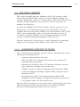
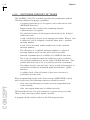
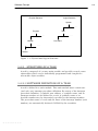
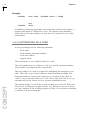
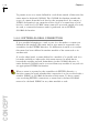
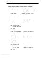
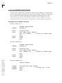
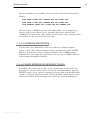
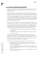
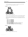
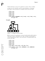
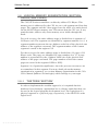
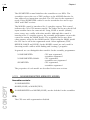
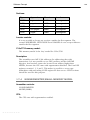
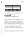
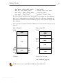

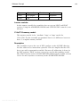
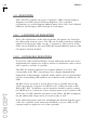
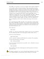
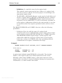
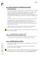
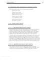
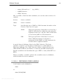
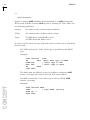
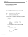
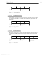
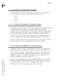
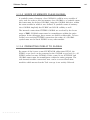


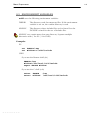

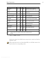


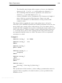
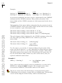
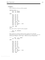
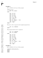
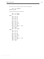
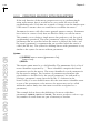

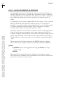
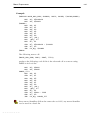
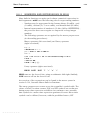
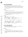
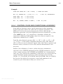
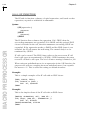
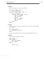
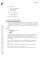

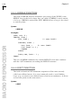
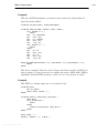
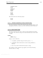
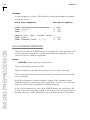

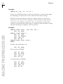
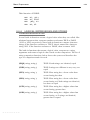
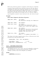
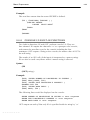
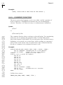
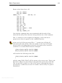
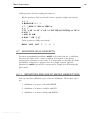
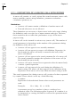
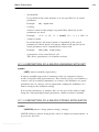
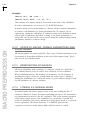
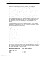
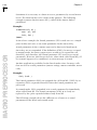
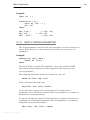
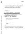
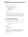
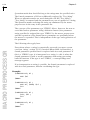
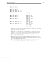
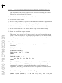


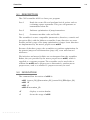
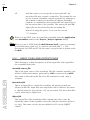
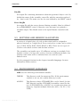


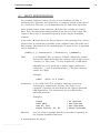

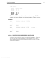
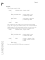
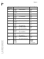
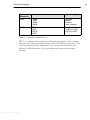
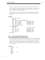


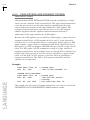


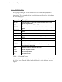
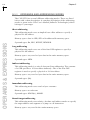
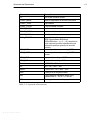
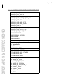
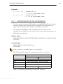
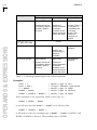
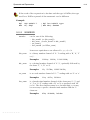
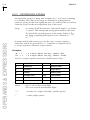
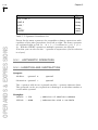
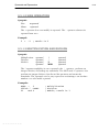
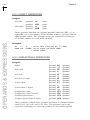
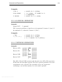
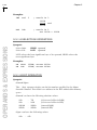
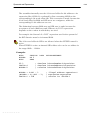
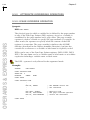
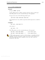
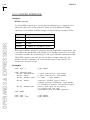
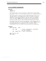
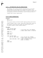
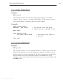
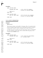
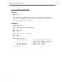
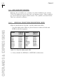
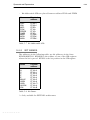


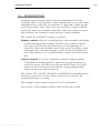
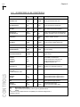
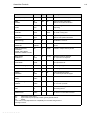
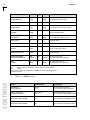
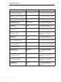
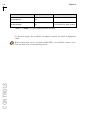


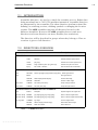
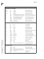

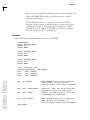
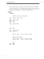
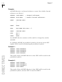
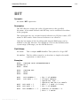
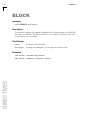
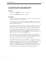
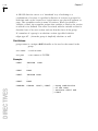
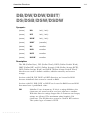
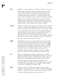
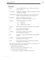


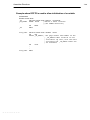
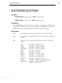
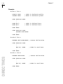
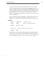
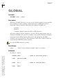
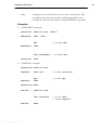
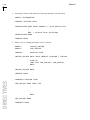

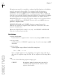
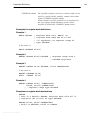
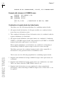
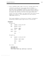
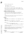
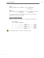
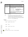
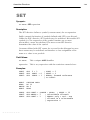
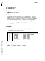
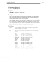


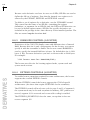


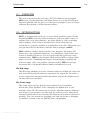
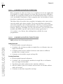
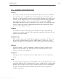
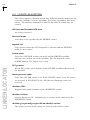
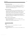
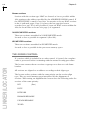
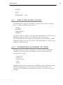
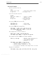
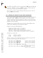
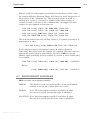
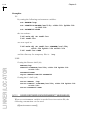
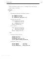
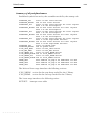
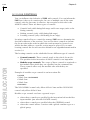
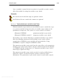
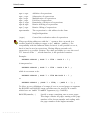
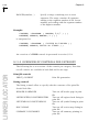
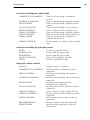
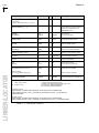
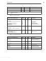
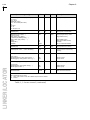
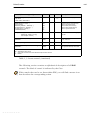
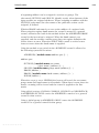
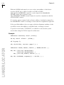


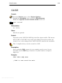

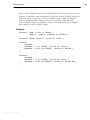
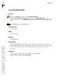
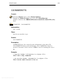
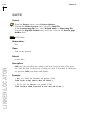


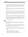
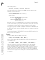

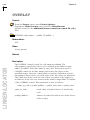

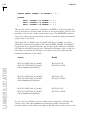


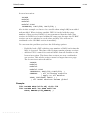
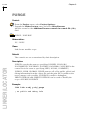
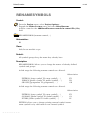
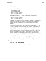

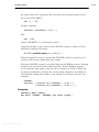
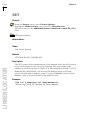


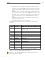
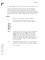
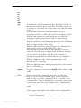
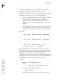
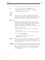
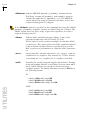


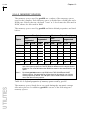
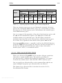
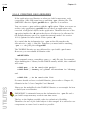

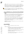

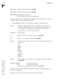
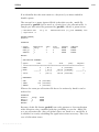
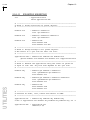
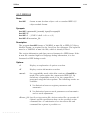

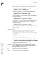
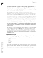
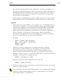
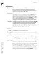
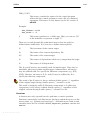
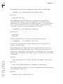
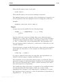
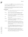


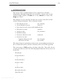
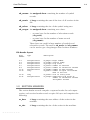
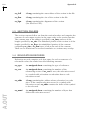
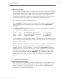
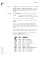
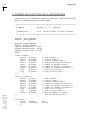
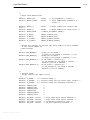
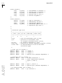
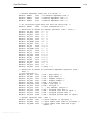
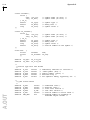
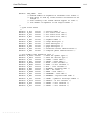
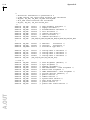
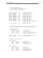
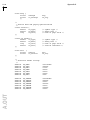
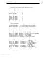


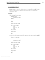
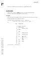
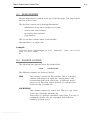
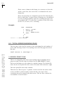


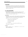
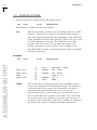
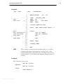
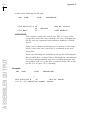
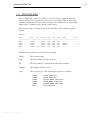
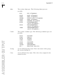
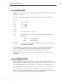
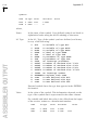
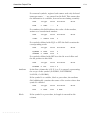


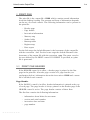
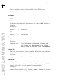
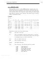
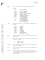
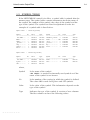
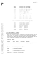
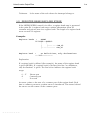
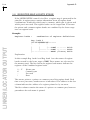
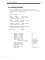
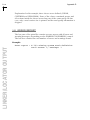


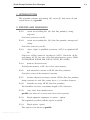
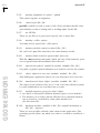
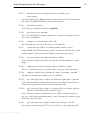
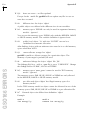


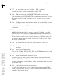
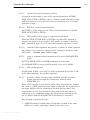
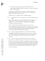
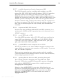
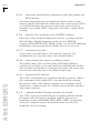
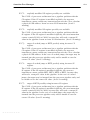
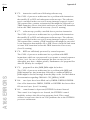
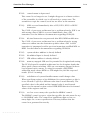

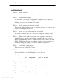
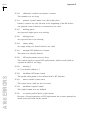
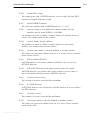
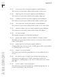
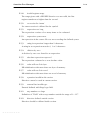

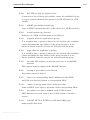
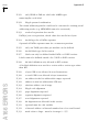
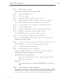
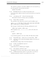
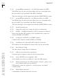

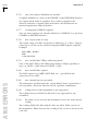
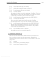


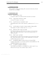
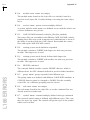
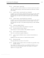
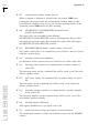
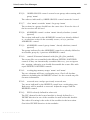
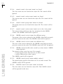
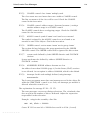
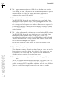
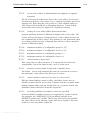
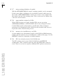
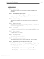
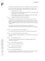
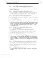
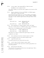
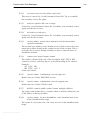
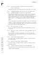
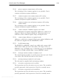

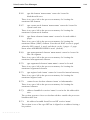


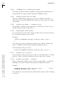
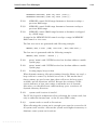
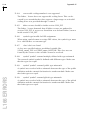
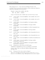
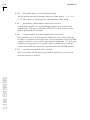
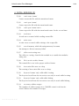
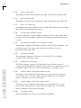
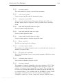
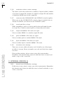


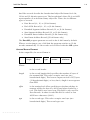
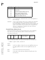
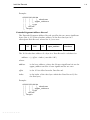
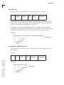
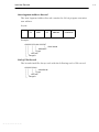


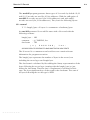

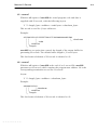
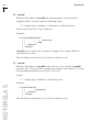


![[U4.43.03] Opérateur AFFE_MATERIAU](http://vs1.manualzilla.com/store/data/006352709_1-66280dcdd9d7ac1974f95651fec4b070-150x150.png)