1
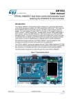
$MPTFE-PPQ4UFQQJOH4ZTUFN
¿.PUPS&ODPEFS%SJWF
¿$MPTFE-PPQ4ZTUFN
¿/P(BJO5VOJOH/P)VOUJOH
¿)JHI3FTPMVUJPO'BTU3FTQPOTF
ú
ú
ú
ú
$MPTFE-PPQ4UFQQJOH4ZTUFN
2
No Gain Tuning
Conventional servo systems, to ensure machine performance,
smoothness, positional error and low servo noise, require
the adjustment of its servo’s gains as an initial crucial
step. Even systems that employ auto-tuning require manual
tweaking after the system is installed, especially if more that
one axis are interdependent. Ezi-SERVO® employs the best
characteristics of stepper and closed loop motion controls
and algorithms to eliminate the need of tedious gain tuning
required for conventional closed loop servo systems. This
means that Ezi-SERVO® is optimized for the application and
ready to work right out of the box! The Ezi-SERVO® system
employs the unique characteristics of the closed loop stepping motor control, eliminating these cumbersome steps and
giving the engineer a high performance servo system without
wasting setup time. Ezi-SERVO® is especially well suited for
low stiffness loads (for example,
a belt and pulley system) that sometime require conventional servo
systems to inertia match
with the added expense
and bulk of a gearbox.
Ezi-SERVO® also performs
exceptionally, even
under heavy loads
and high speeds!
3
No Hunting
Traditional servo motor drives overshoot their position and try
to correct by overshooting the opposite direction, especially
in high gain applications. This is called null hunt and is especially prevalent in systems that the break away or static
friction is significantly higher than the running friction. The
cure is lowering the gain, which affects accuracy or using
Ezi-SERVO® Motion Control System! Ezi-SERVO® utilizes the
unique characteristics of stepping motors and locks itself
into the desired target position, eliminating Null Hunt. This
feature is especially useful in applications such as nanotech
manufacturing, semiconductor fabrication, vision systems and
ink jet printing in which system oscillation and vibration could
be a problem.
Complete stop
1
Closed Loop System
Ezi-SERVO® is an innovative closed loop stepping motor
and controller that utilizes a high-resolution motor mounted
encoder to constantly monitor the motor shaft position. The
encoder feedback feature allows the Ezi-SERVO® to update
the current motor shaft position information every 25 micro
seconds. This allows the Ezi-SERVO® drive to compensate
for the loss of position, ensuring accurate positioning. For
example, due to a sudden load change, a conventional stepper motor and drive could lose a step creating a positioning
error and a great deal of cost to the end user!
Hunting
2
4
Smooth and Accurate
Ezi-SERVO® is a high-precision servo drive, using a highresolution encoder with 32,000 pulses/revolution.
Unlike a conventional Microstep drive, the on-board high
performance DSP
(Digital Signal
Processor) performs
vector control and
filtering, producing
a smooth rotational
control with
minimum ripples.
5
3
High Torque
Compared with common step motors and drives, Ezi-SERVO®
motion control systems can maintain a high torque state over
relatively long period of time. This means that Ezi-SERVO
continuously operates without loss of position under 100% of
the load. Unlike conventional Microstep drives, Ezi-SERVO®
exploits continuous high-torque operation during high-speed
motion due to its innovative optimum current phase control.
Fast Response
Similar to conventional stepping motors, Ezi-SERVO® instantly
synchronizes with command pulses providing fast positional
response. Ezi-SERVO® is the optimum choice when zerospeed stability and rapid motions within a short distance
are required. Traditional servo motor systems have a natural
delay between the commanding input signals and the resultant motion because of the constant monitoring of the current
position, necessitating in a waiting time until it settles, called
settling time.
6
7
High Resolution
The unit of the position command can be divided precisely.
(Max. 20,000 pulses/revolution)
8
High Speed
The Ezi-SERVO® functions well at high speed without the
loss of Synchronism or positioning error. Ezi-SERVO®’s
ability of continuous monitoring of current position enables
the stepping motor to generate high-torque, even under a
100% load condition.
● Part Numbering
● Combination List of Ezi-SERVO-BT
Ezi-SERVO-BT-42S-A-□
Unit Part Number
Ezi-SERVO-BT-42S-A
Closed Loop
Stepping System Name
Ezi-SERVO-BT-42S-B
Motor Flange Size
Ezi-SERVO-BT-42M-B
42 : 42mm
56 : 56mm
60 : 60mm
Ezi-SERVO-BT-42M-A
Ezi-SERVO-BT-42L-A
Ezi-SERVO-BT-42L-B
Ezi-SERVO-BT-42XL-A
Ezi-SERVO-BT-42XL-B
Motor Length
S :
M:
L :
XL:
Single
Middle
Large
Extra Large
Encoder Resolution
A : 10,000/Rev.
B : 20,000/Rev.
Ezi-SERVO-BT-56S-A
Ezi-SERVO-BT-56S-B
Ezi-SERVO-BT-56M-A
Ezi-SERVO-BT-56M-B
Ezi-SERVO-BT-56L-A
Ezi-SERVO-BT-56L-B
Ezi-SERVO-BT-60S-A
Ezi-SERVO-BT-60S-B
Ezi-SERVO-BT-60M-A
Ezi-SERVO-BT-60M-B
User Code
Ezi-SERVO-BT-60L-A
Ezi-SERVO-BT-60L-B
● Advantages over Open-loop Control Stepping Drive
1. Reliable positioning without loss of synchronism.
2. Holding stable position and automatically recovering to the original position even after experiencing positioning error
due to external forces, such as mechanical vibration or vertical positional holding.
3. Ezi-SERVO® utilizes 100% of the full range of rated motor torque, contrary to a conventional open-loop stepping
driver that can use up to 50% of the rated motor torque due to the loss of synchronism.
4. Capability to operate at high speed due to load-dependant current control, open-loop stepper drivers use a constant
current control at all speed ranges without considering load variations.
● Advantages over Servo Motor Controller
1. No gain tuning (Automatic adjustment of gain in response to a load change.)
2. Maintains the stable holding position without oscillation after completing positioning.
3. Fast positioning due to the independent control by on-board DSP.
4. Continuous operation during rapid short-stroke movement due to instantaneous positioning.
4
● Specifications
Input Voltage
Control Method
24VDC ±10%
Closed loop control with 32bit DSP
Operating
Condition
Current Consumption Max 500mA (Except motor current)
Ambient
Temperature
Humidity
Vib. Resist.
In Use : 0~50℃
In Storage : -20~70℃
In Use : 35~85%
In Storage : 10~90%
0.5G
Rotation Speed 0~3000rpm
10,000/Rev. Encoder model : 500 1,000 1,600 2,000 3,600 5,000 6,400 7,200 10,000
Resolution(P/R) 20,000/Rev. Encoder model : 500 1,000 1,600 2,000 3,600 5,000 6,400 7,200 10,000 20,000
(Selectable with Rotary switch)
Function
Max. Input Pulse
500KHz (Duty 50%)
Frequency
Protection
Functions
Over current, Over speed, Position tracking error, Over load, Over temperature,
Over regenerated voltage, Motor connect error, Encoder connect error, Motor voltage error,
In-Position error, System error, ROM error, Position overflow error
In-Position Selection 0~F (Selectable with Rotary switch)
Position Gain Selection 0~F (Selectable with Rotary switch)
Pulse Input Method 1-Pulse / 2-Pulse (Selectable with DIP switch)
I/O Signals
Speed/Position
Pulse train input
Control Command
5
Input Signals
Output Signals
Position command pulse, Servo On/Off, Alarm reset (Photocoupler input)
In-Position, Alarm (Photocoupler output)
Encoder signal (A+, A-, B+, B-, Z+, Z-, 26C31 of Equivalent) (Line Driver output)
42
● Motor Specifications
M O D E L
DRIVE METHOD
NUMBER OF PHASES
VOLTAGE
CURRENT per PHASE
RESISTANCE per PHASE
INDUCTANCE per PHASE
HOLDING TORQUE
ROTOR INERTIA
WEIGHTS
LENGTH (L)
3mm
ALLOWABLE
8mm
OVERHUNG LOAD
(DISTANCE FROM
13mm
END OF SHAFT)
18mm
ALLOWABLE THRUST LOAD
INSULATION RESISTANCE
INSULATION CLASS
OPERATING TEMPERATURE
UNIT
Ezi-SERVO-BT Ezi-SERVO-BT Ezi-SERVO-BT Ezi-SERVO-BT
42S Series
42M Series
42L Series
42XL Series
------VDC
A
Ohm
mH
N·m
g·㎠
g
mm
N
N
MOhm
---℃
BI-POLAR
2
3.36
1.2
2.8
2.5
0.32
35
220
33
22
26
33
46
BI-POLAR
BI-POLAR
2
2
4.32
4.56
1.2
1.2
3.6
3.8
7.2
8
0.44
0.5
54
77
280
350
39
47
22
22
26
26
33
33
46
46
Lower than motor weight
100min. (at 500VDC)
CLASS B (130℃)
0 to 55
BI-POLAR
2
7.2
1.2
6
15.6
0.8
114
500
59
22
26
33
46
● Motor Dimension [mm] and Torque Characteristics
6
※Measured Condition
Motor Voltage = 24VDC
Motor Current = Rated Current (Refer to Motor Specification)
Drive = Ezi-SERVO-BT
● Motor Specifications
M O D E L
DRIVE METHOD
NUMBER OF PHASES
VOLTAGE
CURRENT per PHASE
RESISTANCE per PHASE
INDUCTANCE per PHASE
HOLDING TORQUE
ROTOR INERTIA
WEIGHTS
LENGTH (L)
3mm
ALLOWABLE
8mm
OVERHUNG LOAD
(DISTANCE FROM
13mm
END OF SHAFT)
18mm
ALLOWABLE THRUST LOAD
INSULATION RESISTANCE
INSULATION CLASS
OPERATING TEMPERATURE
UNIT
------VDC
A
Ohm
mH
N·m
g·㎠
g
mm
N
N
MOhm
---℃
56
Ezi-SERVO-BT
56S Series
Ezi-SERVO-BT
56M Series
Ezi-SERVO-BT
56L Series
BI-POLAR
2
1.56
3
0.52
1
0.64
120
500
46
52
65
85
123
BI-POLAR
2
2.1
3
0.54
2
1
200
700
54
52
65
85
123
Lower than motor weight
100min. (at 500VDC)
CLASS B (130℃)
0 to 55
BI-POLAR
2
2.7
3
0.9
3.8
2
480
1150
80
52
65
85
123
● Motor Dimension [mm] and Torque Characteristics
*
7
※Measured Condition
Input Voltage = 24VDC
Motor Current = Rated Current (Refer to Motor Specification)
Drive = Ezi-SERVO-BT
* : There are 2 kinds size of front shaft diameter for Ezi-SERVO-BT-56 series as Φ6.35 and Φ8.0.
● Motor Specifications
M O D E L
DRIVE METHOD
NUMBER OF PHASES
VOLTAGE
CURRENT per PHASE
RESISTANCE per PHASE
INDUCTANCE per PHASE
HOLDING TORQUE
ROTOR INERTIA
WEIGHTS
LENGTH (L)
3mm
ALLOWABLE
8mm
OVERHUNG LOAD
(DISTANCE FROM
13mm
END OF SHAFT)
18mm
ALLOWABLE THRUST LOAD
INSULATION RESISTANCE
INSULATION CLASS
OPERATING TEMPERATURE
UNIT
------VDC
A
Ohm
mH
N·m
g·㎠
g
mm
N
N
MOhm
---℃
60
Ezi-SERVO-BT
60S Series
Ezi-SERVO-BT
60M Series
Ezi-SERVO-BT
60L Series
BI-POLAR
2
1.52
4
0.38
0.64
0.88
140
600
46
70
87
114
165
BI-POLAR
2
1.56
4
0.39
1.2
1.28
320
900
56
70
87
114
165
Lower than motor weight
100min. (at 500VDC)
CLASS B (130℃)
0 to 55
BI-POLAR
2
2.6
4
0.65
2.4
2.4
800
1600
90
70
87
114
165
● Motor Dimension [mm] and Torque Characteristics
8
※Measured Condition
Input Voltage = 24VDC
Motor Current = Rated Current (Refer to Motor Specification)
Drive = Ezi-SERVO-BT
● Setting and Operating
Position Controller Gain(SW2)
Resolution setting(SW3)
In-Position value setting(SW4)
RS-232C connection(CN3)
Power connection(CN2)
Input/Output connection(CN1)
Pulse input selection switch(SW1)
Status Monitor LED
◆ Protection function and LED flash times
When Alarm occurs, can recognize main reason of alarming thru by LED flash times.
Times
1
2
3
Conditions
Over current
Over speed
Position tracking error
The current through power devices in inverter exceeds the limit value
Motor speed exceed 3,000rpm
Position error value is higher than 90˚ in motor run state
The motor is continuously operated more than 5 second under
Over load
a load exceeding the max. torque
Over temperature
Inside temperature of drive exceeds 55℃
Over regeneratived voltage Back-EMF more than 50V
Motor connect error
The power is ON without connection of the motor cable to drive
Encoder connect error
Cable connection error with Encoder connector in drive
Motor voltage error
Motor voltage is less than 20V
In-Position error
After operation is finished, a position error occurs
System error
Error occurs in drive system
ROM error
Error occurs in parameter storage device(ROM)
Position overflow error Position error value is higher than 90˚ in motor stop state
4
5
6
7
8
9
10
11
12
15
9
Protection
Alarm LED flash
(ex : Position tracking error)
1. Pulse input and motor direction selection switch(SW1)
Indication
Switch Name
Functions
2P/1P
Selecting pulse
input mode
Selectable 1-Pulse input mode or 2-Pulse input mode as Pulse input signal.
ON : 1-Pulse mode OFF : 2-Pulse mode ※Default : 2-Pulse mode
2. Resolution selection switch(SW3)
The Number of pulse per revolution.
Position
Pulse/Rotation
Position
0
1
2
3
4
500*1
500
1,000
1,600
2,000
5
6
7
8
9
*1 : Resolution value depend on encoder type.
*2 : Default = 10,000
Pulse/Rotation
3,600
5,000
6,400
7,200
10,000*2
3. Position Controller Gain Selection switch(SW2) 7. Input/Output signal(CN1)
The Position Controller Gain Switch allows for the correction of
the motor position deviation after stopping caused by load and
friction. Depending on the motor load, the user may have to select a different gain position to stabilize and to correct positional
error quickly.
To tune the controller
1. Set the switch to “0” position.
2. Start to rotate the switch until system becomes stable.
3. Rotate the switch +/- 1~2 position to reach better performance.
Position
Time Constant of the Proportional Gain 1
*
Integral part
0
1
2
*23
4
5
6
7
8
9
A
B
C
D
E
F
1
1
1
1
1
1
2
2
2
2
2
3
3
3
3
3
1
2
3
4
5
6
1
2
3
4
5
1
2
3
4
5
NO.
Function
I/O
1
2
3
4
5
6
7
8
9
10
11
12
13
14
15
16
17
18
19
20
CW+(Pulse+)
CW-(Pulse-)
CCW+(Dir+)
CCW-(Dir-)
A+
AB+
BZ+
ZAlarm
In-Position
Servo On/Off
Alarm Reset
NC
BRAKE+
BRAKESignal-GND
24VDC GND
24VDC
Input
Input
Input
Input
Output
Output
Output
Output
Output
Output
Output
Output
Input
Input
---Output
Output
Output
Input
Input
20
2
19
1
*1 : Value in the columns are in relative units.
They only show the parameter changes
depending on the switch’s position.
*2 : Default = 3
4. In-Position Value Setting switch(SW4)
● GUI(Graphic User Interface)
To select the output condition of In-Position signal. In-Position
output signal is generated when the pulse number of positional
error is lower than selected In-Position value set by this switch
after positioning command is executed.
Position
*10
1
2
3
4
5
6
7
In-Position Value[Pulse]
In-Position Value[Pulse]
Position
Fast Response
Accurate Response
0
1
2
3
4
5
6
7
8
9
A
B
C
D
E
F
0
1
2
3
4
5
6
7
*1 : Default = 0
※Please refer to User Manual for setup.
5. Power Connector(CN2)
NO.
Function
1
2
24VDC ±10%
GND
2 1
6. RS-232C Communication(CN3)
Communication Port to set parameter by computer. BaudRate is
115200bps. To set parameter, please use included GUI program.
NO.
Function
1
2
3
Rx
Tx
GND
1 2 3
10
● System Configuration
Type
Power Cable
Signal Cable
Standard Length
Max. Length
2m
20m
1. Cable Option
11
①Signal Cable
③RS-232C Cable
Available to connect between Control System and
Ezi-SERVO-BT.
Cable to connect Ezi-SERVO-BT series and computer.
Please use this cable to change parameter as like
resolution of Drive and Stop current.
Item
Length[m]
Remark
CSVB-S-□□□F
CSVB-S-□□□M
□□□
□□□
Normal Cable
Robot Cable
□ is for Cable Length. The unit is 1m and Max. 20m length.
②Power Cable
Available to connect between Power and
Ezi-SERVO-BT.
Item
Length[m]
Remark
CSVA-P-□□□F
CSVA-P-□□□M
□□□
□□□
Normal Cable
Robot Cable
□ is for Cable Length. The unit is 1m and Max. 20m length.
Item
Length[m]
Remark
CBTB-C-□□□F
□□□
Normal Cable
□ is for Cable Length. The unit is 1m and Max. 15m length.
2. Option
④FAS-UCR(USB to RS-232C Converter)
Item
Comm. Speed
Comm. Distance
Connector Type
IP Address
IRQ Number
Dimension
Weight
Power
Specification
115.2Kbps default
USB : Max. 5m
RS-232C : Max. 15m
USB : USB Standard
RS-232C : DB9 Femail
Automatic Setting
Automatic Setting
50X69X23mm
31g
USB self power
(No need External power)
USB Cable
Item
Length[m]
Remark
CGNR-U-002F
CGNR-U-003F
CGNR-U-005F
2
3
5
Normal Cable
3. Connector for Cabling
ITEM
Power Connector (CN2)
Signal Connector (CN1)
RS-232C Connetor (CN3)
Specification
Maker
Terminal Block
AKZ1550/2F-3.81
PTR
Housing
501646-2000
MOLEX
Terminal
501648-1000(AWG 26~28)
MOLEX
Housing
33507-0300
MOLEX
Terminal
50212-8100
MOLEX
※These connectors are serviced together with Ezi-SERVO-BT except when purchasing option cables.
※Above connector is the most suitable product for Ezi-SERVO-BT. Another equivalent connector can be used.
12
● External Wiring Diagram
13
● Control Signal input/output Description
1
Input signal
Input signals of the drive are all photocoupler protected. The signal shows the status of internal photocouplers
[ON: conduction], [OFF: Non-conduction], not displaying the voltage levels of the signal.
◆ Servo On/Off Input
This input can be used only to adjust the position by manually moving the motor shaft from the load-side. By setting the
signal [ON], the driver cuts off the power supply to the motor.
Then, one can manually adjust output position. When setting
the signal back to [OFF], the driver resumes the power to the
motor and recovers the holding torque. When driving a motor,
one needs to set the signal [OFF].
CW(Pin:1,2), CCW(Pin:3,4)
◆ CW, CCW Input
Alarm Reset (Pin:14)
Servo On/Off(Pin:13)
This signal can be used to receive a positioning pulse command
from a user host motion controller. The user can select 1-pulse
input mode or 2-pulse input mode (refer to switch No.1, SW1).
The input schematic of CW, CCW is designed for 5V TTL level.
When using 5V level as an input signal, the resistor Rx is not used
and connect to the driver directly.
When the level of input signal is more than 5V, Rx resistor is required. If the resistor is absent, the drive will be damaged!
If the input signal level is 12V, Rx value is 2.2Kohm and 24V, Rx
value is 4.7Kohm.
2
◆ Alarm Reset Input
When a protection mode has been activated, a signal to this
alarm reset input cancels the Alarm output.
※ By setting the alarm reset input signal [ON], cancel the Alarm output.
Before cancel the Alarm output, have to remove the source of alarm.
Output signals
Output signals from the driver are photocoupler protected: Alarm, In-Position and the Line Driver Outputs (encoder signal).
In the case of photocoupler outputs, the signal indicates the status of internal photocouplers [ON: conduction], [OFF: Nonconduction], not displaying the voltage levels of the signal.
◆ In-Position Output
In-Position signal is [ON] when positioning is completed. This
signal is [ON] when the motor position error is within the value
set by the switch SW4.
14
Alarm(Pin:11), In-Position(Pin:12)
Encoder signal
(Pin:5,6,7,8,9,10)
◆ Alarm Output
The Alarm output indicates [ON] when the driver is in a normal
operation. If a protection mode has been activated, it goes [OFF]. A
host controller needs to detect this signal and stop sending a motor
driving command. When the driver detects an abnormal operation
such as overload or over current of the motor, it sets the Alarm
output to [OFF], flashes the Alarm LED, disconnect the power to a
motor and stops the motor simultaneously.
[Caution] Only at the Alarm output port, the photocoupler isolation is in
reverse. When the driver is in normal operation the Alarm output
is [ON]. On the contrary when the driver is in abnormal operation
that start protection mode, the Alarm output is [OFF].
◆ Encoder signal Output
The encoder signal is a line driver output. This can be used to
confirm the stop position.
ⓒCopyright 2010 FASTECH Co,. Ltd.
All Rights Reserved. Oct 14, 2010 Rev.05