1
Insert to document GEK-64459D and GEK-64460A
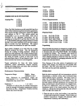
Breaker operation
This is an insert to the maintenance manuals for
AKR 30/50 (GEK 64459D) and AKR 75/100
(GEK64460A). The insert describes the operation of the
breaker with the newly introduced electronic closing
system.
For the AKR 30/50 insert to section 5 starting on
page 11.
For the AKR 75/100 insert to section 4 starting on
page 10
Replacement Parts
Replacement printed circuit board assembly for 48
VDC applications: #10060126G1
Replacement printed circuit board assembly for all
other voltage applications: #10060126G2
2/10/97
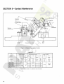
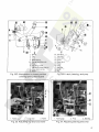
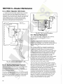
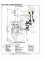
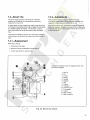
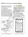
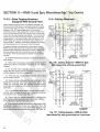
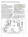
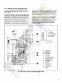
E.2 ELECTRICAL CLOSING
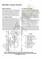
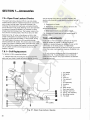
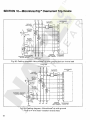
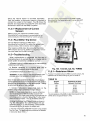
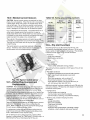
On electrically operated breakers the closing
springs are charged by a gear motor. With the springs
discharged, voltage applied to the control circuit will
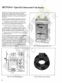
energize the motor through the "G" switch contacts - see
Fig. E1. The motor, through the gear reduction output
crank, compresses the closing spring until they are fully
charged. As this fUlly charged position is reached,
mechanically operated switches "F" and "G" reverse their
shown position, the "G" switch deenergizing the motor
and the "F" switch establishing a circuit to the One-Shot
electronic.
With the closing spring propped fUlly-charged, the
breaker is ready for closing. This may be accomplished
electrically by depressing the closing switch "PB" on the
breaker (if so equipped) or by a remote closing switch.
Operation of the closing switch energizes the One-Shot
electronic, witch in turn energizes the closing solenoid
"CC". This removes the prop, releasing the closing
springs to close the breaker.
As the One-Shot electronic is energized through a
closing contact, the "X" relay is energized as well. The
"X" relay will latch in and therefore prevent a second
closing operation on the breaker in the event it is tripped
open automatically. The closing signal must be released
and reapplied before a second closing operation can
occur.
The closing springs on the electrically operated breakers
can be manually charged.
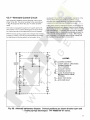
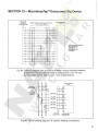
(X)
(+)
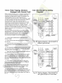
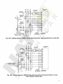
LEGEND
CC
F
G
L
M
PB
(Y)
(-)
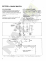
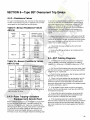
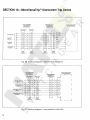
FIG.E1 - ELEMENTARY DIAGRAM FOR
ELECTRICALLY OPERATED DRAWOUT BREAKER.
CONTACT POSITIONS ARE SHOWN WITH BREAKER
OPEN AND CLOSING SPRINGS DISCHARGED. TYP #
183L712 &# 568B736 "E" SERIES
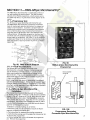
X
OS
CLOSING SOLENOID
CUTOFF SWITCH, CLOSED WHEN
CLOSING SPRING IS FULLY
CHARGED.
CUTOFF SWITCH. OPEN WHEN
CLOSING SPRING IS FULLY
CHARGED.
AUXILIARY SWITCH
CHARGING MOTOR
CLOSE PUSH-BUTTON ON BREAKER
ESCUTCHEON, OPTIONAL.
CONTROL RELAY
ONE-SHOT ELECTRONIC. PULSES
THE CLOSING SOLENOID FOR
250 MSEC.