1
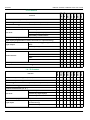
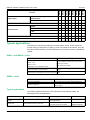
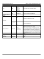
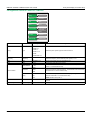
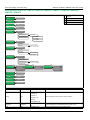
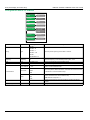
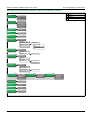
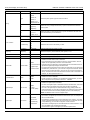
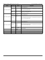
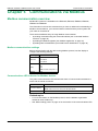
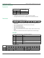
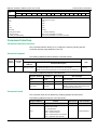
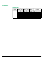
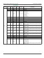
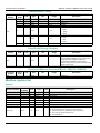
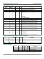
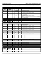
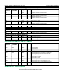
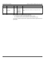
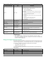
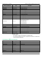
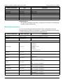
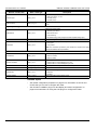
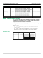
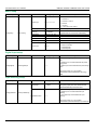
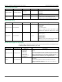
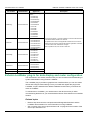
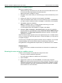
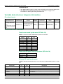
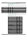
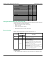
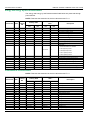
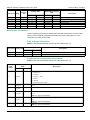
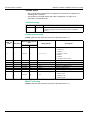
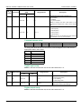
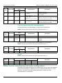
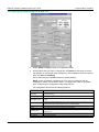
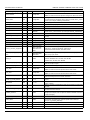
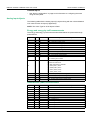
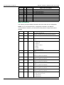
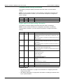
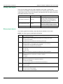
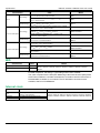
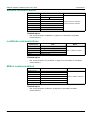
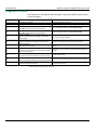
iEM3100 / iEM3200 / iEM3300 series user manual
Communications via M-Bus
Description
bin
CT Secondary
E010 1010
hex
2A
VT connection type
E010 1011
2B
Energy pulse duration
E010 1100
2C
Digital output association with active energy pulsing E010 1101
2D
Pulse weight
2E
E010 1110
Pulse constant
E010 1111
2F
Digital input association
E011 0000
30
Digital input status
E011 0010
32
Overload alarm setup
E011 0100
34
Pickup setpoint
E011 0101
35
Digital output association with overload alarm
E011 0110
36
Activated status
E011 0111
37
Acknowledgment
E011 1000
38
Date and time of last alarm
E011 1001
39
Value at last alarm
E011 1010
3A
Telegram information for data records
The following sections outline the telegram information used in data records. The tables
contain the following information (if applicable):
•
•
•
•
Data format in hex (for example, 16-bit integer)
Primary VIF in hex
Primary VIFE codes in bin and hex
Manufacturer-specific VIFE codes in bin and hex
Meter information
NOTE: E denotes the extension bit; the hex value assumes E = 0.
Primary VIF
Extension
Data format
bin
Description
hex
0D
E000 1010 0A
0D
E000 1100
0C
Manufacturer
18-bit ASCII = Schneider Electric
Model
Meter error codes:
0 = Code 101: EEPROM error
1 = Code 102: No calibration table
2 = Code 201: Mismatch between frequency settings and frequency
measurements
3 = Code 202: Mismatch between wiring settings and wiring inputs
03
E0001 0111 17
4 = Code 203: Phase sequence reversed
5 = Code 204: Total active energy negative due to incorrect voltage or
current connections
6 = Code 205: Date and time are reset due to a power failure
7 = Code 206: Pulse missing due to overspeed of energy pulse output
8 = Code 207: Abnormal internal clock function
9 = Internal data bus communications error
Related topics
•
DOCA0005EN-05
See “Troubleshooting” on page 93 for more information on the diagnostics codes.
67