1
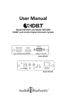
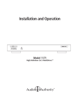
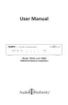
2800 SERIES
Models 2801, 2811
Table of Contents
WARNINGS . . . . . . . . . . . . . . . . . . . . . . 3
INTRODUCTION . . . . . . . . . . . . . . . . . . . 3
CHECKING PACKAGE CONTENTS . . . . . . . . . 3
SYSTEM FEATURES. . . . . . . . . . . . . . . . . 4
APPLICATIONS. . . . . . . . . . . . . . . . . . . . 5
HDMI EXTENSION. . . . . . . . . . . . . . . . . .
5
HDMI DISTRIBUTION NETWORK. . . . . . . . . .
6
TROUBLESHOOTING . . . . . . . . . . . . . . . . 8
SPECIFICATIONS. . . . . . . . . . . . . . . . . . 10
LIMITED WARRANTY . . . . . . . . . . . . . . . . 11
WARNINGS
• Read these instructions before installing or using this product.
• To reduce the risk of fire or electric shock, do not expose this unit to rain or
moisture.
• This product must be installed by qualified personnel.
• Do not open the cover—there are no user-serviceable parts inside.
• Do not expose this unit to excessive heat.
• Install only in dry, indoor locations.
• Clean the unit only with a dry or slightly dampened soft cloth.
LIABILITY STATEMENT
Every effort has been made to ensure that this product is free of defects.
Audio Authority® cannot be held liable for the use of this hardware or any direct
or indirect consequential damages arising from its use. It is the responsibility of
the user of the hardware to check that it is suitable for his/her requirements and
that it is installed correctly. All rights are reserved. No parts of this manual may
be reproduced or transmitted by any form or means electronic or mechanical,
including photocopying, recording or by any information storage or retrieval
system without the written consent of the publisher.
Audio Authority reserves the right to revise any of its hardware and software
following its policy to modify and/or improve its products where necessary or
desirable.
Audio Authority and the Double-A Symbol are registered trademarks of Audio
Authority Corp. Copyright April, 2010. HDMI, the HDMI Logo, and High-Definition
Multimedia Interface are trademarks or registered trademarks of HDMI Licensing
LLC in the United States and other countries. All other third party trademarks and
copyrights are recognized.
2
INTRODUCTION
Thank you for purchasing this 2800 Series HD-IP™ distribution system from
Audio Authority®. The 2800 Series transmits HDMI® signals from one source over
a dedicated Gigabit network via Cat 5e/6 cables to achieve distances many times
those possible using an HDMI cable. Ultra high speed GbE (Gigabit Ethernet)
preserves ultra high quality 720p or 1080p video content. This manual presents
one to one, and one to many configurations.
HDMI® TECHNOLOGY AND THE HD-IP ADVANTAGE
Standard HDMI® devices transmit video and audio using a signaling method
called TMDS (Transition Minimized Differential Signaling). TMDS was designed
for short cable runs, like those necessary to connect a cable box to an HDTV in
an entertainment center. Unfortunately, TMDS has some limitations. Very high
frequency signals like HDMI tend to “roll off” as cable runs get longer. Since
differential pairs are used for each of the three color channels and the separate
clock channel, differences in individual wire lengths inside HDMI cables can
cause timing errors and blank screens.
HD-IP technology utilizes Ethernet standards to overcome the inherent limitations
of TMDS. Enabling reliable cable runs up to 250 feet and farther, easy distribution
of signals, and robust signal integrity, transmitting HDMI signals over IP networks
redefines the possibilities for HDMI video distribution. Compliant with HDCP
2.0 specifications, this technology supports copy protection with 128-bit AES
encryption and overcomes traditional key verification limitations, enabling very
large system sizes while maintaining full HDCP compliance. Audio Authority’s
Gigabit infrastructure means that the picture quality is virtually indistinguishable
from the source, suitable for a wide range of applications.
CHECKING PACKAGE CONTENTS
Before connecting the 2800 system, please make certain the following items are
in the their respective shipping cartons.
2801 Transmitter
2811 Receiver
• 5V 2A power adapter
• 5V 2A power adapter
• Two mounting Plates
• Two mounting Plates
• Self adhesive rubber feet
• Self adhesive rubber feet
• Product manual
• Product manual
Note: Please retain the original packing material and invoice in case you need to return
the unit. If you find any items are missing, contact Audio Authority immediately. Have the
model number and invoice available for reference when you call.
3
SYSTEM FEATURES
• Supports 720p and 1080p and embedded digital audio (2-channel PCM)
• Gigabit Ethernet (GbE, 1000BASE-T) technology for excellent picture quality
• Uses off-the-shelf GbE network switches for distribution
• Requires only one UTP cable per position (Cat 5e or Cat 6)
• Quick synchronization means maximum up-time
• Basic installation is plug and play – no complex setup routines or programming
• Designed to function on a separate, dedicated Gigabit Ethernet network
• Cascading multiple network switches and cable runs allows maximum
distribution distances of 1000+ ft. (300m) when necessary
• HDMI version 1.3 and HDCP version 2.0 compliant
• IR can be transmitted over the UTP cable back to the source location
POWER
5V DC
ETHERNET
HDMI OUTPUT
IR OUT
HDMI INPUT
IR OUT
HDMI OUTPUT
IR OUT
HDMI INPUT
IR OUT
Transmitter – Model 2801
POWER
5V DC
ETHERNET
Receiver – Model 2811
IR IN
POWER
5V DC
ETHERNET
POWER
5V DC
ETHERNET
4
APPLICATIONS
HD-IP is designed to function as an HDMI extender (point to point), or as a
distribution system via a dedicated network (single source).
HDMI EXTENSION
SOURCE
Model 2801
HDMI
The example below depicts the HD-IP system
in a basic HDMI extension application.
NOTE: DIAGRAMS
DO NOT SHOW
POWER SUPPLY
CONNECTIONS
TV
Model 2811
HDMI
In extension applications (point to point), the transmitter may be connected
directly to the receiver, for distances up to 250 ft. (75m), using Cat 6 cable. Cat 5
cable may also be used, but range varies depending on the quality of the cable. A
GbE network switch can be added in a Cat 6 path to effectively double the range.
RX
TX
CAT 6 CABLE UP TO 250 FT.
In this configuration, HDMI cables connect the source and display equipment
to the respective 2801 Transmitter and 2811 Receiver. A Cat 5 or 6 UTP cable
connects the 2801 to the 2811. Properly terminated Cat 6 cables will result in
the longest possible range. Terminate the cables to either the EIA 568A or 568B
standard for best performance. Correct pairing is vital, and should always be
checked with a network cable tester. The DIP switches on the 2801 and 2811
should all be in the DOWN position.
USING THE IR PATHWAY
IR signals can be passed from a 2811 Receiver back to the 2801 Transmitter to
control the source equipment. Most 3rd party IR receivers are compatible with
the system when used with a connecting block. Be advised that environmental
conditions such as Plasma/LCD televisions, fluorescent lighting and sunlight
might adversely affect the performance of your IR receivers. 1.With power disconnected from the 2811 Receiver,
Tip =
Signal
Tip
= (+)
connect your IR receiver and its power supply to
Ring
=
Ground
a standard 12V IR connecting block. Connect a
= (–)
SleeveSleeve
= +12 Volts
MONO 3.5mm cable from the emitter output of the
connecting block to the 2811’s 3.5mm IR port. Pin out is shown.
IR
2.With power disconnected from the 2801
Transmitter, connect a standard IR emitter to the
2801’s IR 3.5mm IR port. Pin out is shown. CONNECTION
NOTE: The 2800 system may not be compatible with all IR equipment.
5
DISTRIBUTION NETWORK
In distribution network applications, a single transmitter (or multiple transmitters)
may be connected to several receivers, for distances up to 250 ft. (75m) using
Cat 6 cable. Cat 5 cable may also be used, but distances will vary depending on
the quality of the cable used. A Gigabit Ethernet (GbE) switch is used in the Cat 6
path to distribute the video signals.
SINGLE TRANSMITTER NETWORK
The 2800 system can distribute a single source signal to multiple displays on
the same network using a standard Gigabit Ethernet switch (GbE) – a managed
switch is not required. In this application, the number of displays is only limited by
the number of available ports on the GbE switch.
The example below depicts the 2800 system
in a single transmitter HDMI network application.
2801
TV
HDMI
HDMI
SINGLE SOURCE
GbE SWITCH
TX
CAT 5e/6
NOTE: DIAGRAMS
DO NOT SHOW
POWER SUPPLY
CONNECTIONS
2811
RX
2811 and TV
2811 and TV
GbE SWITCH
2811 and TV
2811 and TV
2811 and TV
CAT 5e/6
2811 and TV
2811 and TV
2811 and TV
GbE SWITCH
In this configuration, HDMI cables connect the source and display equipment to
the 2801 Transmitter and 2811 Receivers. Cat 5e/6 cables connect the 2801 and
2811s to the GbE switch. GbE switches may be cascaded to accommodate large
HDMI network systems or allow for future system expansion. Properly terminated
Cat 6 cables will generally provide better results at longer distances. All UTP
cables should be terminated to either the EIA 568A or 568B standard for best
performance. Correct pairing is essential, and should always be checked with a
network cable tester. The DIP switches on the 2801 and 2811s should all be in
the DOWN position.
USING THE IR PATHWAY
IR signals can be passed from 2811 Receivers back to the 2801 Transmitter to
control the source equipment. Most 3rd party IR receivers are compatible with
the system when used with a connecting block. Be advised that environmental
conditions such as Plasma/LCD televisions, fluorescent lighting and sunlight
might adversely affect the performance of your IR receivers and prevent proper
operation of IR control through the 2800 system. 6
1.With power disconnected from the 2811 Receiver,
Tip =
Signal
Tip
= (+)
connect your IR receiver and its power supply to
Ring
=
Ground
a standard 12V IR connecting block. Connect a
= (–)
SleeveSleeve
= +12 Volts
MONO 3.5mm cable from the emitter output of the
connecting block to the 2811’s 3.5mm IR port. Pin out is shown.
IR
2.With power disconnected from the 2801
Transmitter, connect a standard IR emitter to the
2801’s IR 3.5mm IR port. Pin out is shown. CONNECTION
NOTE: The 2800 system may not be compatible with all IR equipment.
7
TROUBLESHOOTING
• Poor image quality: For the best results, always use high quality 720p or
1080p content. Some sources, particularly cable and satellite providers,
transmit compressed video resulting in poor image quality. Consider the
source material when planning and troubleshooting your system. The 2800
Series does not require any adjustment.
• Intermittent signal dropout: make sure the 2800 Series is not connected
to any other devices, or sharing a network with other traffic, especially with
access to the internet. Make sure all 2801 transmitters are set to a unique
“channel” (see page 12). Also make sure no AC wiring is installed within two
feet of the 2800 Series network cables.
• No surround sound (multi-channel audio): this system does not support
multi-channel digital audio transmission; adjust the source to output 2-channel
PCM digital audio.
• No picture: perform the verifications below.
• Check the HDMI cables at input and output connections to see if any of the
connectors have become loose.
• Make certain 2801 and 2811 units are connected to live AC outlets and
check the power indicators on all units.
• Use a network cable tester to make certain your Cat 5e/6 cable is terminated
correctly and the RJ-45 connectors are securely attached to the cable at
both ends. Check for cable defects or damage.
• Connect the display device directly to the source using the HDMI cable
from the 2801 end, then test with the 2811 connection cable. If an image
is present under those circumstances then the display, the source, and the
HDMI cables can be eliminated as the cause of the problem.
• If the above circumstances do not produce a picture, test using a short,
known good HDMI cable, and set up the source to output a resolution that
the display can accept (720p or 1080p). If successful, connect the 2800
Series again, making sure the source resolution is the same as the test.
If you encounter difficulty, contact the Audio Authority Technical Service via email:
[email protected], or call 800-322-8346 or 859‑233-4599. 8
CONSIDERATIONS FOR GETTING THE BEST RESULTS
Many factors influence the quality and reliability of an HDMI® signal distribution
installation. The following are the main factors to consider, and basic precautions
that will ensure the best possible performance.
• Dedicated network. The 2800 Series is designed to operate on a dedicated
Gigabit Ethernet network, not to be combined with other network traffic
competing for access to the internet.
• Resolution tracking. The 2800 Series supports 720p and 1080p. If some TVs
in the network are not capable of accepting 1080p, the higher resolution sets
may not be shown to their best advantage. Set up the source to output the
best resolution that all TVs are capable of displaying, or use one source with
720p resolution output, and another with 1080p output (See page 7).
• Source resolution and video/sound quality. Sources, such as satellite
receivers or cable boxes, can output at low resolutions or deliver extremely
compressed video material, yielding poor results. Consider the source material
when planning and troubleshooting your system.
• Display devices. The perceived quality of the video image depends heavily
upon the type and quality of the TVs or projectors used. High quality displays
should be expected to produce a noticeably better image, given high quality
source material.
• Distance between the transmitter and the receiver. Long distances are
possible, but premium quality Cat 6 cables are necessary for the longest runs.
When necessary, insert a network switch to extend long cable runs.
• Source and TV connection cables. Use short, high quality HDMI cables.
Always use good strain relief methods to prevent cables from becoming loose
over time.
• Interference from nearby electrical devices can have an adverse effect
on signal quality. For example, older computer monitors often emit very high
electromagnetic fields that can interfere with the performance of nearby video
equipment.
9
SPECIFICATIONS
DIGITAL AUDIO/VIDEO I/O
2801 Transmitter
1x via HDMI connector – HDMI input
2811 Receiver
1x via HDMI connector – HDMI output
CAT 5E/6 CONNECTIONS I/O
2801 Transmitter
1x via RJ-45 – Cat 5e/6 output
2811 Receiver
1x via RJ-45 – Cat 5e/6 input
VIDEO PERFORMANCE
Minimum resolution
720p
Maximum resolution
1080p (1920x720, 1080p/60Hz)
TMDS clock speed (HDMI)
225MHz
Data bit rate (HDMI)
2.25Gbps
Maximum range
250 ft. (75m) direct connection
1000 ft. (300m) extended via three GbE switches
AUDIO PERFORMANCE
Digital Audio
2-channel PCM audio only
ENVIRONMENTAL
Operating Temperature
0° to +50° C (+32° to +122° F)
Operating Humidity
10% to 90%, Non-condensing
Storage Temperature
-10° to +70° C (12° to +158° F)
Storage Humidity
10% to 90%, non-condensing
REGULATORY APPROVALS
2801 and 2811
HDMI, HDCP, RoHS
Power Supply
UL, CUL, CE, PSE, GS, RoHS
NETWORK REQUIREMENTS
Cat 5, Cat 5e or Cat 6
Network grade, premium
Network Switch Compatibility
Standard or Managed Gigabit Ethernet 1000BASE-T
network switch depending on application
MECHANICAL
Product Weight (Net)
2801 / 2811: 2.25 lb. (1kg)
Dimensions: H-W-D inches (mm)
2801 and 2811: 1.25 x 6.35 x 4.5 (32x162x115)
ACCESSORIES INCLUDED
Power Adapter
5 VDC@2A 2801/2811
User Manual
Printed, 12 pages
WARRANTY
Limited Warranty: 1 year parts and labor
10
LIMITED WARRANTY
If any consumer product from Audio Authority® fails due to defects in materials or
workmanship within one year from the date of the original sale to the end-user, Audio
Authority guarantees that we will replace the defective product at no cost. Freight charges
for the replacement unit will be paid by Audio Authority (ground service only). A copy of
the invoice showing the item number and date of purchase (proof-of-purchase) must be
submitted with the defective unit to constitute a valid in-warranty claim.
Units that fail after the warranty period has expired may be returned to the factory for repair
at a nominal charge, if not damaged beyond the point of repair. All freight charges for
out-of-warranty returns for repair are the responsibility of the customer. Units returned for
repair must have a Return Authorization Number assigned by the factory.
This is a limited warranty and is not applicable for products which, in our opinion, have
been damaged, altered, abused, misused, or improperly installed. Audio Authority makes
no other warranties either expressed or implied, including limitation warranties as to
merchantability or fitness for a particular purpose. Additionally, there are no allowances or
credits available for service work or installation performed in the field by the end user.
REGULATORY COMPLIANCE
The 2801 and 2811 comply with HDMI® and HDCP rules and regulations. Power supplies
included have been tested for compliance with UL, CUL, CE, PSE, and GS rules and
guidelines.
11
2048 Mercer Road, Lexington, Kentucky 40511-1071
Phone: 859-233-4599 • Fax: 859-233-4510
Customer Toll-Free USA & Canada: 800-322-8346
www.audioauthority.com
752-603
20131001