1
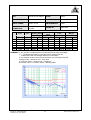
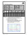
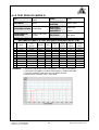
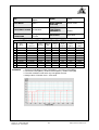
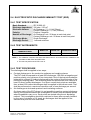
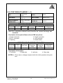
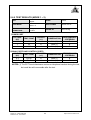
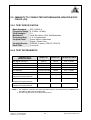
4
EMISSION TEST
4.1 CONDUCTED EMISSION MEASUREMENT
4.1.1 LIMITS OF CONDUCTED EMISSION MEASUREMENT
TEST STANDARD: EN55022
FREQUENCY (MHz)
0.15 - 0.5
0.50 - 5.0
5.0 - 30.0
NOTE:
Class A (dBuV)
Quasi-peak Average
79
66
73
60
73
60
Class B (dBuV)
Quasi-peak Average
66 - 56
56 - 46
56
46
60
50
(1) The lower limit shall apply at the transition frequencies.
(2) The limit decreases in line with the logarithm of the frequency in the range of 0.15 to
0.50 MHz.
(3) All emanations from a class A/B digital device or system, including any network of
conductors and apparatus connected thereto, shall not exceed the level of field
strengths specified above.
4.1.2 TEST INSTRUMENTS
DESCRIPTION &
MANUFACTURER
MODEL NO.
SERIAL NO.
CALIBRATED
UNTIL
ROHDE & SCHWARZ
Test Receiver
ESCS 30
847124/029
Dec. 14, 2006
Line-Impedance Stabilization
Network(for EUT)
ENV-216
100072
Oct. 05, 2006
KYORITSU LISN (for peripheral)
KNW-407
8/1395/12
Jul. 19, 2006
RF Cable (JETBAO)
RG233/U
Cable_CA_01
Jul. 19, 2006
Terminator(for KYORITSU)
50
1
Oct. 08, 2006
Software
Cond-V2e
NA
NA
NOTE: 1. The calibration interval of the above test instruments is 12 months and the calibrations are
traceable to NML/ROC and NIST/USA.
2. The test was performed in ADT Shielded Room No. A.
3. The VCCI Con A Registration No. is C-817.
Report No.: CE941006H04B
Reference No.: 941219H04
13
Report Format Version 2.0.4