1
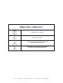
MANUALE DI INSTALLAZIONE, USO
E MANUTENZIONE
INSTALLATION, OPERATION &
MAINTENANCE MANUAL
UNITA’ VENTILANTI CASSONATE
FAN BOX UNITS
SERIE CTE – CTT
SERIES CTE - CTT
L.M.F. srl
via Paradiso 1/B
36040 Meledo di Sarego (Vi)
Tel. 0444 821279 r.a. Fax 0444 820323
SIMBOLOGIA / SYMBOLOGY
AVVERTENZA / ATTENTION
PERICOLO / DANGER
PERICOLO RISCHIO DI SCOSSE ELETTRICHE
HIGH RISK OF ELECTRIC SHOCK
ATTENZIONE SOLO PERSONALE AUTORIZZATO
ATTENTION AUTHORIZED PERSONNEL ONLY
L.M.F. srl
via Paradiso 1/B
36040 Meledo di Sarego (Vi)
Tel. 0444 821279 r.a. Fax 0444 820323
INSTALLATION & MAINTENANCE MANUAL
PAG.
3
INTRODUZIONE
INTRODUCTION
Gentile Cliente,
questa gamma di unità ventilanti è stata progettata
e realizzata per poter soddisfare le esigenze di
immissione/estrazione d’aria di piccoli e medi
impianti di ventilazione.
Essa è composta di due serie :
- CTE con ventilatore direttamente accoppiato
al motore elettrico, a singola o tripla velocità,
per portate d’aria da 250 a 8000 m3/h e
pressioni statiche fino a 500 Pa
- CTT con ventilatore accoppiato al motore
elettrico mediante cinghie e pulegge,
disponibile anche a doppia velocità, per
portate d’aria da 1500 a 16000 m3/h e
pressioni statiche fino a 700 Pa
Le elevate pressioni statiche utili permettono
l’applicazioni anche in impianti dotati di
canalizzazioni di lunga tratta.
Dear Customer,
this range of fan boxes has been designed and
manufactured to satisfy the air demand of small
and medium size ventilation plants.
L.M.F. srl
via Paradiso 1/B
It includes two types of units :
- CTE equipped with direct driven fan and
single-speed or three-speed electric motor to
cover 250 up to 8000 m3/h airflow rate range
and up to 500 Pa external static pressure
- CTT equipped with belt driven fan and singlespeed or two-speed electric motor to cover
1500 up to 16000 m3/h airflow rate range and
up to 700 Pa external static pressure
Because of high external static pressure, these
units are suitable to be installed in long air duct
plants also.
36040 Meledo di Sarego (Vi)
Tel. 0444 821279 r.a. Fax 0444 820323
MANUALE INSTALLAZIONE E MANUTENZIONE
INDICE
PAG.
4
INDEX
SEZIONE 1 – CARATTERISTICHE TECNICHE
1.1 Caratteristiche generali
1.2 Dimensioni d’ingombro
1.3 Dati tecnici
1.4 Prestazioni aerauliche
pag. 5
pag. 6
pag. 7
pag. 8
SECTION 1 – TECHNICAL FEATURES
1.1 General features
1.2 Unit dimensions
1.3 Unit technical data
1.4 Air performance
page 5
page 6
page 7
page 8
SEZIONE 2 – ACCESSORI
2.1 Accessori disponibili
pag. 12
SECTION 2 – ACCESSORIES
2.1 Available accessories
page 12
SEZIONE 3 – TRASPORTO
3.1 Imballaggio
3.2 Movimentazione e trasporto
3.3 Controllo al ricevimento
3.4 Stoccaggio
pag. 17
pag. 17
pag. 17
pag. 17
SECTION 3 – TRANSPORTATION
3.1 Packing
3.2 Transport and moving
3.3 Checking on arrival
3.4 Storage
page 17
page 17
page 17
page 17
SEZIONE 4 – INSTALLAZIONE E MESSA IN
SERVIZIO
4.1 Definizioni
pag. 18
4.2 Norme di sicurezza
pag. 18
4.3 Operazioni preliminari
pag. 19
4.4 Luogo di installazione
pag. 19
4.5 Collegamento ai canali
pag. 20
4.6 Collegamenti elettrici
pag. 20
SECTION 4 – INSTALLATION AND START-UP
4.1 Definitions
4.2 Safety regulations
4.3 Preliminary operations
4.4 Choice of installation site
4.5 Duct connection
4.6 Electrical connection
page 18
page 18
page 19
page 19
page 20
page 20
SEZIONE 5 – SCHEMI ELETTRICI
5.1 Collegamento diretto CTE 1-ph 1-vel.
5.2 Collegamento unità trifase (max 5,5 kW)
5.3 Collegamento unità trifase (oltre 5,5 kW)
5.4 Collegamento diretto CTT 2-vel.
5.5 Collegamento CTE 1-ph 1-vel. tramite RCS
5.6 Collegamento CTT 2-velocità tramite CDP
5.7 Collegamento CTE 1-ph 3-vel. tramite RCV
SECTION 5 – ELECTRICAL DIAGRAMS
5.1 1-ph 1-speed CTE unit direct connection
5.2 3-ph unit connection (up to 5,5 kW)
5.3 3-ph unit connection (over 5,5 kW)
5.4 2-speed CTT unit direct connection
5.5 1-ph 1-speed CTE unit connection by RCS
5.6 2-speed CTT unit connection by CDP
5.7 1-ph 3-speed CTE unit connection by RCV
page 21
page 21
page 22
page 22
page 23
page 24
page 24
SEZIONE
6
–
DELL’AVVIAMENTO
6.1 Controlli preliminari.
CONTROLLI
pag. 21
pag. 21
pag. 22
pag. 22
pag. 23
pag. 24
pag. 24
PRIMA
pag. 25
SECTION 6 – PRE-START-UP CHECKS
6.1 Pre-start-up checks
page 25
SEZIONE 7 – MANUTENZIONE ORDINARIA
7.1 Controlli mensili
pag. 26
7.2 Controlli annuali
pag. 26
SECTION 7 – ORDINARY MAINTENANCE
7.1 Monthly checks
7.2 Yearly checks
page 26
page 26
SEZIONE 8 – LOCALIZZAZIONE DEI GUASTI
8.1 Localizzazione dei guasti
pag. 28
SECTION 8 – FAULT FINDING
8.1 Fault finding
page 28
SEZIONE 9 – SMANTELLAMENTO
9.1 Smantellamento
SECTION 9 – DISMANTLEMENT
9.1 Dismantlement
page 28
L.M.F. srl
via Paradiso 1/B
pag. 28
36040 Meledo di Sarego (Vi)
Tel. 0444 821279 r.a. Fax 0444 820323
INSTALLATION & MAINTENANCE MANUAL
SEZIONE 1
TECNICHE
–
CARATTERISTICHE
PAG.
5
SECTION 1 – TECHNICAL FEATURES
1.1 CARATTERISTICHE GENERALI
1.1 GENERAL FEATURES
• Struttura portante e pannelli di chiusura in acciaio zincato
• Isolamento acustico in lastre adesive di poliestere in classe
1
• Ispezionabilità dell’unità attraverso un pannello laterale,
incernierato per la serie CTT, bloccato con chiusure a ¼ di
giro per la serie CTE
• Ventilatori centrifughi a pale avanti a doppia aspirazione a
velocità singola o multipla, staticamente e dinamicamente
bilanciati, accoppiati direttamente (serie CTE) o tramite
cinghie e pulegge (serie CTT) al motore elettrico; il gruppo
motoventilante è dotato di supporti antivibranti in gomma
per attenuare la trasmissione delle vibrazioni
• Elemento pressacavo installato sul pannello frontale per la
realizzazione delle connessioni elettriche al motore
• Frame and panels made from galvanized steel sheet metal
• Sound insulation by class 1 polyester adhesive sheets
• Unit inspection by one side panel, provided with hinges for
CTT series and with ¼ rotation locking system for CTE
series
• Single or multi-speed double inlet forward curved fans,
statically and dynamically balanced; direct driven fans for
CTE series and belt driven fans for CTT series; fan-motor
group mounted on rubber anti-vibrators
• Cable gland fitted on the unit front panel for the electric
connections to the motor
L.M.F. srl
via Paradiso 1/B
36040 Meledo di Sarego (Vi)
Tel. 0444 821279 r.a. Fax 0444 820323
MANUALE INSTALLAZIONE E MANUTENZIONE
1.2 DIMENSIONI D’INGOMBRO
MODELLO
MODEL
CTE
CTE
CTE
CTE
CTT
CTT
CTT
CTT
CTT
574-576
694-696
614-616
726
809
810
912
1115
1218
PAG.
6
1.2 UNIT DIMENSIONS
A (mm)
B (mm)
D (mm)
E (mm)
F (mm)
G (mm)
H (mm)
Peso
Weight (kg)
500
600
600
700
800
800
900
1100
1300
500
600
600
700
600
600
700
800
1100
111
149
93
115
125
69
91
103
214
218
272
299
351
272
299
351
414
478
171
179
208
234
203
232
258
283
408
129
146
129
147
146
130
148
160
271
242
308
342
406
308
340
405
480
558
25-30
35-40
40-45
60-70
60-65
65-70
70-80
100-120
170-180
L.M.F. srl
via Paradiso 1/B
36040 Meledo di Sarego (Vi)
Tel. 0444 821279 r.a. Fax 0444 820323
INSTALLATION & MAINTENANCE MANUAL
PAG.
7
1.3 UNIT TECHNICAL DATA
1.3 DATI TECNICI
Caratteristiche elettriche serie CTE / CTE series electrical specifications
MODELLO
MODEL
576
576V
574D
574DV
696
696V
694D
694DV
616
616V
614D
614V
726
726V
726T
Potenza motore
Motor power
W
62
147
147
147
147
245
300
420
245
245
373
420
736
736
1100
Assorbimento max
Max current
A
1,0
1,1
1,8
1,9
2,1
2,5
3,5
3,8
2,6
3,0
4,8
4,1
7,5
6,8
4,5
N° velocità
Fan speeds
1
3
1
3
1
3
1
3
1
3
1
3
1
3
1
Protezione
Protection
IP
20
32
20
20
20
20
20
20
20
20
20
20
20
20
20
Cl. isolamento
Temp. class
B
B
B
B
B
F
B
B
B
F
B
B
B
F
B
Alimentazione
Power supply
V
ph Hz
230
1
50
230
1
50
230
1
50
230
1
50
230
1
50
230
1
50
230
1
50
230
1
50
230
1
50
230
1
50
230
1
50
230
1
50
230
1
50
230
1
50
400
3
50
Caratteristiche elettriche serie CTT / CTT series electrical specifications
MODELLO
MODEL
809
810
912
1115
1218
MODELLO
MODEL
Potenza motore min/max
Min/Max motor power
kW
0,18/1,1
0,25/2,2
0,37/3,0
0,75/5,5
0,75/7,5
N° velocità
Fan speeds
1 (2)
1 (2)
1 (2)
1 (2)
1 (2)
Protezione
Protection
IP
55
55
55
55
55
Cl. isolamento
Temp. class
F
F
F
F
F
Alimentazione
Power supply
V
ph Hz
400
3
50
400
3
50
400
3
50
400
3
50
400
3
50
LIMITE DI ASSORBIMENTO VENTILATORI / FAN-MOTOR CURRENT LIMIT [A]
Motore installato / Fan-motor power
[kW] (*)
0,18
0,25
0,37
0,55
0,75
1,1
CTT 809
0,6
0,8
1,1
1,5
2,0
2,7
CTT 810
0,8
1,1
1,5
2,0
2,7
CTT 912
1,1
1,5
2,0
2,7
CTT 1115
2,0
2,7
CTT 1218
2,0
2,7
(*) Per versioni a doppia velocità (4/6 poli), potenza minima motore 0,37 kW
(*) For double speed version (4/6 pole type), min. motor power 0,37 kW
L.M.F. srl
via Paradiso 1/B
36040 Meledo di Sarego (Vi)
1,5
3,6
3,6
3,6
3,6
2,2
5,0
5,0
5,0
5,0
3,0
6,5
6,5
6,5
4,0
8,5
8,5
Tel. 0444 821279 r.a. Fax 0444 820323
5,5
11,5
11,5
7,5
15,4
MANUALE INSTALLAZIONE E MANUTENZIONE
PAG.
8
1.4 PRESTAZIONI AERAULICHE
1.4 AIR PERFORMANCE
I seguenti diagrammi riportano le curve caratteristiche delle
unità della serie CTE alle velocità disponibili e le pressioni
sonore a 1 metro [dB(A)].
The following curves are the air performances of CTE units,
size by size at the available fan speeds; moreover, sound
pressure levels [dB(A)] at 1 m are shown.
CTE 574 DV
CTE 574 D
320
59,6 dB(A)
280
240
Pressione statica / Static pressure (Pa)
60,1
200
160
60,6
120
80
40
280
61,6 dB(A)
240
200
59,7
160
57,5
80
61,8
40
51,4
0
1750
1500
1250
1000
750
Portata aria / Airflow rate (mc/h)
CTE 576 V
CTE 576
160
160
54,0
80
60
40
56,7
20
0
54,1 dB(A)
120
100
56,1
80
49,6
60
53,3
40
20
60,4
52,9
1000
750
500
250
0
1500
1250
1000
750
500
0
250
0
Portata aria / Airflow rate (mc/h)
Portata aria / Airflow rate (mc/h)
CTE 614 V
CTE 614 D
650
550
600
500
450
550
64,6 dB(A)
500
350
64,1
450
67,5 dB(A)
400
64,0
300
63,6
400
59,5
250
200
350
150
300
52,5
52,5
100
250
51,0
50
3250
3000
2750
2500
2250
2000
1750
1500
1250
1000
750
500
250
0
200
Portata aria / Airflow rate (mc/h)
L.M.F. srl
via Paradiso 1/B
36040 Meledo di Sarego (Vi)
0
44,0
P or t a t a a r i a / A i r f l o w r a t e
Tel. 0444 821279 r.a. Fax 0444 820323
( m c / h)
1750
100
140
1500
51,8 dB(A)
120
1250
140
Pressione statica / Static pressure ( Pa)
Pressione statica / Static pressure (Pa)
500
0
1750
1500
1250
1000
750
500
250
0
0
Portata aria / Airflow rate (mc/h)
Pressione static / Static pressure (Pa)
62,0
57,4
120
250
Pressione statica / Static pressure (Pa)
320
INSTALLATION & MAINTENANCE MANUAL
320
Pressione statica / Static pressure (Pa)
56,0 dB(A)
200
57,9
160
120
80
40
280
57,6 dB(A)
240
58,4
200
56,0
54,0
160
120
54,5
80
57,9
40
48,0
440
440
3000
2750
2500
2250
2000
1750
3000
2750
44,8
0
2750
2500
2250
2000
1750
1500
1250
0
1000
0
750
40
500
63,6
80
40
250
1500
120
2500
80
55,7
51,9
160
2250
120
200
2000
160
63,9
240
1750
200
280
1500
240
1250
63,7
280
63,4 dB(A)
60,1
320
1000
320
360
750
62,0
400
500
60,0 dB(A)
250
Pressione statica / Static pressure (Pa)
480
0
1250
CTE 694 DV
CTE 694 D
480
360
1000
Portata aria / Airflow rate (mc/h)
Portata aria / Airflow rate (mc/h)
400
750
0
3000
2750
2500
2250
2000
1750
1500
1250
1000
750
500
250
0
500
0
250
Portata aria / Airflow rate (mc/h)
Portata aria / Airflow rate (mc/h)
CTE 696 V
CTE 696
240
80
40
51,6
Portata aria / Airflow rate (mc/h)
L.M.F. srl
via Paradiso 1/B
36040 Meledo di Sarego (Vi)
Tel. 0444 821279 r.a. Fax 0444 820323
3000
2750
2500
0
2250
Portata aria / Airflow rate (mc/h)
63,6
56,9
2000
2500
2250
2000
1750
1500
1250
1000
750
500
250
0
0
54,6
1750
40
57,0
120
1500
80
61,1
160
1250
60,3
60,7 dB(A)
750
120
200
500
57,6
250
55,3 dB(A)
160
0
Pressione statica / Static pressure (Pa)
200
1000
Pressione statica / Static pressure (Pa)
240
0
Pressione statica / Static pressure (Pa)
9
CTE 616 V
CTE 616
280
Pressione statica / Static pressure (Pa)
PAG.
MANUALE INSTALLAZIONE E MANUTENZIONE
500
450
450
400
350
65,4 dB(A)
69,1
300
250
200
150
100
50
400
350
66,3 dB(A)
66,3
300
250
63,0
62,0
200
68,0
150
65,2
100
60,2
50
CTE 726 T
500
450
400
64,0 dB(A)
68,0
300
250
200
150
100
74,9
50
9000
8000
7000
6000
5000
4000
3000
2000
1000
0
0
Portata aria / Airflow rate (mc/h)
L.M.F. srl
via Paradiso 1/B
36040 Meledo di Sarego (Vi)
Tel. 0444 821279 r.a. Fax 0444 820323
6500
6000
5500
5000
4500
Portata aria / Airflow rate (mc/h)
Portata aria / Airflow rate (mc/h)
350
4000
3500
3000
2500
2000
1500
1000
500
6000
5500
5000
4500
4000
3500
3000
2500
2000
1500
1000
500
0
0
0
0
Pressione statica / Static pressure (Pa)
10
CTE 726 V
500
Pressione statica / Static pressure (Pa)
Pressione statica / Static pressure (Pa)
CTE 726
PAG.
INSTALLATION & MAINTENANCE MANUAL
La seguente tabella consente la rapida selezione delle unità
CTT in funzione della portata d’aria e prevalenza richieste;
essa permette, inoltre, di stabilire la potenza elettrica
installata (kW) e la pressione sonora a 1 metro dalla bocca
premente.
MODELLO
MODEL
CTT 809
CTT 810
CTT 912
CTT 1115
CTT 1218
Portata aria
Airflow rate
[mc/h]
1500
2000
2500
3000
2000
3000
4000
4000
5000
6000
7000
7000
8000
9000
10000
12000
9000
10000
12000
14000
16000
L.M.F. srl
PAG.
The following table is useful for a fast selection of CTT units
by the required airflow rate and static pressure; it shows,
moreover, the motor power (kW) for the required
performance and the sound pressure level at 1 m far from the
fan outlet.
Pressione statica / Static pressure
[Pa]
100
200
300
400
500
kW dBA kW dBA kW dBA kW dBA kW dBA
0,18 53 0,18 58 0,37 63
0,18 58 0,25 60 0,37 63 0,55 66 0,75 69
0,25 63 0,37 63 0,55 65 0,75 67 0,75 69
0,37 67 0,55 67 0,75 68 0,75 69
1,1
70
0,18 55 0,25 59 0,37 63
0,25 61 0,37 63 0,55 65 0,75 67
1,1
69
0,55 67 0,75 68
1,1
69
1,1
70
1,5
71
0,37 61 0,55 63 0,75 66
1,1
69
1,5
71
0,55 66 0,75 67
1,1
68
1,5
70
1,5
71
0,75 70
1,1
70
1,5
71
1,5
72
2,2
73
1,1
73
1,5
73
2,2
74
2,2
74
2,2
75
0,75 68
1,1
69
1,5
69
2,2
71
2,2
72
1,1
71
1,5
71
1,5
71
2,2
72
2,2
74
1,5
73
2,2
74
2,2
74
2,2
74
3,0
75
2,2
76
3,0
76
3,0
76
3,0
77
3,0
79
4,0
79
4,0
80
5,5
80
0,75 68
1,1
68
2,2
69
2,2
70
3,0
72
1,1
70
1,5
70
2,2
70
2,2
71
3,0
73
1,5
75
2,2
76
3,0
74
3,0
74
4,0
75
2,2
78
3,0
78
4,0
78
4,0
78
5.,5
78
3,0
81
4,0
81
4,0
81
5,5
81
5,5
81
via Paradiso 1/B
11
36040 Meledo di Sarego (Vi)
600
kW dBA
700
kW dBA
1,1
1,1
71
71
1,1
1,5
73
73
1,1
1,5
71
73
1,5
2,2
73
74
2,2
2,2
3,0
3,0
3,0
3,0
4,0
5,5
3,0
4,0
4,0
5,5
7,5
73
74
76
73
75
76
77
80
73
74
76
78
82
2,2
3,0
3,0
3,0
3,0
4,0
4,0
5,5
4,0
4,0
5,5
5,5
7,5
75
75
76
75
76
77
78
81
75
75
77
79
82
Tel. 0444 821279 r.a. Fax 0444 820323
MANUALE INSTALLAZIONE E MANUTENZIONE
PAG.
12
SEZIONE 2 – ACCESSORI
SECTION 2 – ACCESSORIES
2.1 ACCESSORI DISPONIBILI
2.1 AVAILABLE ACCESSORIES
Le serie CTE-CTT dispongono di una serie completa di
accessori da consentire un perfetto adattamento alla maggior
parte delle destinazioni d’uso e delle tipologie di impianto.
Per ciascun modello, possono essere selezionati i seguenti :
•
TP tettuccio parapioggia
•
CU cuffia di espulsione con rete antivolatile
•
PD piedi di appoggio
•
SG serranda di sovrappressione
•
RCS regolatore elettronico velocità (per motori
monofase versione a singola velocità)
•
RCV regolatore velocità a 3 posizioni (per motori
monofase a 3 velocità)
•
CDP regolatore velocità a 2 posizioni (per serie CTT a
doppia polarità)
CTE-CTT series can be provided with a complete series of
accessories to allow a perfect adaptation to the most of
compact installations.
For each model, the following accessories can be selected :
•
TP roof cover
•
CU casing with bird net
•
PD support legs
•
SG overpressure damper
•
RCS electronic speed regulator (for single phase
single speed motors)
•
RCV 3-speed selector (for single phase 3-speed
motors)
•
CDP 2-speed selector (for double speed CTT series)
L.M.F. srl
via Paradiso 1/B
36040 Meledo di Sarego (Vi)
Tel. 0444 821279 r.a. Fax 0444 820323
INSTALLATION & MAINTENANCE MANUAL
PAG.
13
2.1.1 TETTUCCIO PARAPIOGGIA TP
2.1.1 ROOF COVER TP
Costruito in lamiera zincata, viene utilizzato per fornire un
riparo all’unità ventilante quando la stessa è posta alle
intemperie.
Made from galvanized sheet metal, it is used to protect the
unit itself when mounted outdoors.
MODELLO/MODEL
500 - 600
700
800
900
1100
1200
DIMENSIONI / DIMENSIONS [mm]
650 x 650 x 25
800 x 800 x 25
900 x 700 x 25
1100 x 850 x 25
1200 x 1050 x 25
1400 x 1200 x 25
2.1.2 CUFFIA CON RETE ANTIVOLATILE CU
2.1.2 CASING WITH BIRD NET CU
Deve essere impiegata quando l’unità è posta all’esterno e
con premente non canalizzato; essa è realizzata in lamiera
zincata, con forma ed accorgimenti tali da non consentire
l’ingresso di acqua e/o corpi estranei.
It must be used when the unit is placed outdoors and with
not-ducted outlet; it is made from galvanized sheet metal and
designed in a way that it can’t receive water or other objects
inside.
MODELLO/MODEL
500
600 - 800
700 - 900
1100
1200
L.M.F. srl
A (mm)
310
310
410
410
510
via Paradiso 1/B
36040 Meledo di Sarego (Vi)
B (mm)
300
400
400
500
600
Tel. 0444 821279 r.a. Fax 0444 820323
C (mm)
250
250
320
320
410
MANUALE INSTALLAZIONE E MANUTENZIONE
PAG.
14
2.1.3 PIEDINI D’APPOGGIO PD
2.1.3 SUPPORT LEGS PD
Costruiti in lamiera zincata di adeguato spessore e dotati di
occhiello di sollevamento, vengono posti sotto l’unità e
consentono alla stessa di non appoggiare direttamente sul
pavimento.
Made from galvanized sheet metal of adequate thickness and
provided with a hole for the lifting, they are mounted under
the unit and allow it not to lay on the floor directly.
MODELLO/MODEL
500 – 600 – 700 – 800 - 900
1100 - 1200
A (mm)
110
250
B (mm)
100
100
2.1.4 SERRANDA DI SOVRAPPRESSIONE SG
2.1.4 OVERPRESSURE DAMPER SG
Installata sulla mandata dell’unità e realizzata in alluminio,
essa consente la chiusura automatica per gravità all’arresto
del ventilatore.
Installed on the fan outlet and made from aluminium, it
allows the automatic closing by gravity when fan stops.
MODELLO/MODEL
500
600 - 800
700 - 900
1100
1200
L.M.F. srl
via Paradiso 1/B
A (mm)
310
310
410
410
510
36040 Meledo di Sarego (Vi)
B (mm)
300
400
400
500
600
Tel. 0444 821279 r.a. Fax 0444 820323
INSTALLATION & MAINTENANCE MANUAL
2.1.5
REGOLATORE
VELOCITA’ RCS
ELETTRONICO
PAG.
15
2.1.5 ELECTRONIC SPEED CONTROLLER
RCS
E’ idoneo alla regolazione manuale della portata d’aria delle
unità serie CTE monofase a singola velocità, sul principio del
taglio di fase. A seconda della corrente assorbita dal motore è
possibile scegliere tra quattro modelli.
It is suitable for airflow rate adjustment or control for one
phase one-speed CTE units, by cutting phase. According to
the motor current, it allows to choose between four controller
sizes.
Installazione
Installation
1.
2.
3.
4.
1.
2.
3.
5.
Svitare le viti frontali
Togliere il coperchio
Fissare a muro la basetta con le viti fornite in dotazione
Eseguire i collegamenti secondo gli schemi riportati
nella sezione 5 e comunque forniti insieme
all’accessorio
Riposizionare e il coperchio e riavvitare le viti
Unscrew the front screw
Remove the cover
Fix the base on the wall by using the screws supplied
together
4. Carry out the electrical connections according to the
electrical wirings in section 5 and always supplied with
the RCS accessory
5. Replace the cover and tighten the screws
Modello / Model
Adottabile su CTE / Adoptable on CTE units
RCS 1,5
576
RCS 3
574D – 696 – 616
RCS 5
614D – 694D
RCS 7,5
726
Alimentazione 230 Vac 50/60 Hz; campo di regolazione da 40% a 100% Vmax
Power supply 230 Vac 50/60 Hz; control range 40% to 100% Vmax
L.M.F. srl
via Paradiso 1/B
36040 Meledo di Sarego (Vi)
Tel. 0444 821279 r.a. Fax 0444 820323
MANUALE INSTALLAZIONE E MANUTENZIONE
2.1.6 REGOLATORE
POSIZIONI RCV
VELOCITA’
A
3
PAG.
16
2.1.6 3-SPEED SELECTOR
RCV
E’ idoneo alla regolazione manuale della portata d’aria di una
qualsiasi delle unità serie CTE a tre velocità.
It is suitable for airflow rate adjustment or control for any 3speed CTE unit, by 3+1 position knob.
Installazione
1
Svitare la vite superiore, togliere il pomello rotante ed
aprire l’involucro
2. Eseguire i collegamenti secondo gli schemi riportati
nella sezione 5 e comunque forniti insieme
all’accessorio
3. Richiudere l’involucro e riposizionare il pomello
Installation
1. Unscrew the upper screw, remove the moving knob and
open the box
2. Carry out the electrical connections according to the
electrical wirings in section 5 and always supplied with
the RCV accessory
3. Close the box and replace the knob
2.1.7 REGOLATORE
POSIZIONI CDP
2.1.7 2-SPEED SELECTOR
CDP
VELOCITA’
A
2
E’ idoneo alla regolazione manuale della portata d’aria delle
unità serie CTT a doppia velocità (versioni a 4/6 poli). A
seconda della potenza installata è possibile scegliere tra due
modelli (09 – 20).
It is suitable for airflow rate adjustment or control for 2speed (4/6 pole motor version) CTT units, by 2+1 position
knob. According to the motor power, it allows to choose
between two controller sizes (09 – 20).
Installazione
1
Svitare le viti frontali e togliere il coperchio
2
Eseguire i collegamenti secondo gli schemi riportati
nella sezione 5 e comunque forniti insieme
all’accessorio
3
Riposizionare e il coperchio e riavvitare le viti
Installation
1 Unscrew the front screw and remove the cover
2
Carry out the electrical connections according to the
electrical wirings in section 5 and always supplied with
the CDP accessory
3
Replace the cover and tighten the screws
Modello / Model
CDP 09
CDP 20
Alimentazione 400 Vac 50/60 Hz
Power supply 400 Vac 50/60 Hz
L.M.F. srl
via Paradiso 1/B
per potenze installate fino a / for motor power up to [kW]
4
7,5
36040 Meledo di Sarego (Vi)
Tel. 0444 821279 r.a. Fax 0444 820323
INSTALLATION & MAINTENANCE MANUAL
PAG.
17
SEZIONE 3 – TRASPORTO
SECTION 3 – TRANSPORTATION
3.1 IMBALLAGGIO
3.1 PACKING
Le unità ventilanti e i loro accessori sono inseriti in scatole di
cartone che dovranno rimanere integre fino al momento del
montaggio.
I materiali che non sono stati installati per esigenze tecniche
vengono forniti imballati con involucro idoneo fissato
all'interno o esterno dell'unità stessa.
The fan box units and accessories are packed in cardboard
boxes. The packing must remain intact until mounting.
The material which has not been installed for technical
reasons is supplied packed with appropriate packaging fixed
to the inside or outside of the unit itself.
3.2 MOVIMENTAZIONE E TRASPORTO
3.2 TRANSPORT AND MOVING
Per la movimentazione utilizzare, in funzione del peso mezzi
adeguati come previsto dalla direttiva 89/391/CEE e
successive modifiche.
Il peso di ogni singola macchina è riportato sul seguente
manuale.
Evitare rotazioni senza controllo.
for moving use, according to weight, adequate means as
provided for the 89/391 CEE regulations and subsequent
modifications.
The weight of every single machine is given in the following
manual.
Avoid uncontrolled rotation.
3.3 CONTROLLO AL RICEVIMENTO
3.3 CHECKING ON ARRIVAL
Al ricevimento dell’unità Vi preghiamo di effettuare un
controllo di tutte le parti, al fine di verificare che il trasporto
non abbia causato danneggiamenti, i danni eventualmente
presenti devono essere comunicati al vettore, apponendo la
clausola di riserva nella bolla di accompagnamento,
specificandone il tipo di danno.
On arrival of the unit we recommend that all the parts are
checked, to make sure that no damages have accrued during
transport. Any damage must be communicated to the carrier,
by completing the clauses reserved on the transport
document, specifying the type of damage.
3.4 STOCCAGGIO
3.4 STORAGE
In caso di stoccaggio prolungato mantenere le macchine
protette dalla polvere e lontano da fonti di vibrazioni e di
calore.
If prolonged storage is necessary, protect the machine from
dust and keep it away from heat and vibration sources
La ditta costruttrice declina ogni responsabilità per
danneggiamenti dovuti a cattivo scarico o per
mancata protezione dagli agenti atmosferici.
The manufacturer will not be responsible for any damage
caused by bad unloading, loading or lack of protection from
environmental agents.
L.M.F. srl
via Paradiso 1/B
36040 Meledo di Sarego (Vi)
Tel. 0444 821279 r.a. Fax 0444 820323
MANUALE INSTALLAZIONE E MANUTENZIONE
PAG.
18
SEZIONE 4 – INSTALLAZIONE E
MESSA IN SERVIZIO
SECTION 4 – INSTALLATION AND START
UP
4.1 DEFINIZIONI
4.1 DEFINITIONS
UTENTE – L’utente è la persona, l'ente o la società, che ha
acquistato o affittato la macchina e che intende usarla per gli
scopi concepiti.
USER – The user is the person, the company or society who
has brought or rented the machine and intends to use it for its
designed purpose.
UTILIZZATORE / OPERATORE – L’utilizzatore o
operatore, è la persona fisica che è stata autorizzata
dall'utente a operare con la macchina.
USER / OPERATOR – The user or operator, is the physical
person who has been authorized by the user to operate in the
machine.
PERSONALE SPECIALIZZATO - Come tali, si intendono
quelle persone fisiche che hanno conseguito uno studio
specifico e che sono quindi in grado di riconoscere i pericoli
derivati dall'utilizzo di questa macchina e possono essere in
grado di evitarli.
SPECIALIZED PERSONNEL – This is intended as
physical persons who have a specific qualification and are
therefore able to recognize and avoid the dangers arising
from its use.
4.2 NORME DI SICUREZZA
4.2 SAFETY REGULATIONS
La Ditta Costruttrice declina qualsiasi responsabilità per
la mancata osservanza delle norme di sicurezza e di
prevenzione di seguito descritte.
Declina inoltre ogni responsabilità per danni causati da
un uso improprio delle unità e/o da modifiche eseguite
senza autorizzazione.
•
•
•
•
•
•
•
The manufacturer will not be responsible for any lack of
observance of safety regulations as describe in the
following. The manufacturer declines any responsibility
for any damage caused by improper use of the unit and/or
not authorised modifications.
L'installazione deve essere effettuata da
personale specializzato.
Nelle operazioni di installazione, usare un
abbigliamento idoneo e antinfortunistico, ad
esempio: occhiali, guanti, ecc. come indicato
da norma 686/89/CEE e successive.
Durante l’installazione operare in assoluta
sicurezza, ambiente pulito e libero da
impedimenti.
Rispettare le leggi in vigore nel Paese in cui
viene installata la macchina, relativamente
all'uso e allo smaltimento dell'imballo e dei
prodotti impiegati per la pulizia e la
manutenzione della macchina, nonché
osservare quanto raccomanda il produttore di
tali prodotti.
Prima di mettere in funzione l’unità
controllare la perfetta integrità dei vari
componenti e dell'intero impianto.
Evitare assolutamente di toccare le parti in
movimento o di interporsi tra le stesse.
Non procedere con i lavori di manutenzione
e di pulizia, se prima non è stata disinserita
la linea elettrica. Per i modelli a
trasmissione
e
necessario
inoltre
provvedere al isolamento del motore dal
ventilatore prima di ogni manutenzione.
L.M.F. srl
via Paradiso 1/B
36040 Meledo di Sarego (Vi)
•
•
•
•
•
•
•
The installation must be carried out by able and
qualified personnel.
During the installation, use protective clothing, for
example safety glasses, gloves etc. as described in
the 686/89/CEE and successive regulations.
Carry out the installation in safe conditions, clean
environments free from obstacles.
The laws in force, relative to the use and scrapping
of the packaging and the products used for
cleaning and machine maintenance, in the country
of machine installation and cause the indications
given by the product manufacturer must be
respected.
Before starting the machine check the integrity and
safety of the various components inside the
machine.
Avoid toughing the moving parts or parts located
between these parts.
Do not carry out any maintenance and cleaning
operation, if the machine is not disconnected to
the power supply. For transmission models it is
also necessary to disconnect the ventilator motor
before carrying out any maintenance.
Tel. 0444 821279 r.a. Fax 0444 820323
INSTALLATION & MAINTENANCE MANUAL
•
•
•
La manutenzione e la sostituzione delle parti
danneggiate o usurate deve essere effettuata
solamente da personale specializzato e seguendo le
indicazioni riportate in questo manuale.
In caso di smantellamento delle unità, attenersi alle
normative antinquinamento previste.
PAG.
19
The maintenance and replacement must be carried
out exclusively by qualified personnel and
following indication given in this manual
In case of unit dismantlement, follow the local
pollution legislation.
•
N.B. L’installatore e l’utilizzatore nell’uso dell’unità devono
tenere conto e porre rimedio a tutti gli altri tipi di rischio
connessi con l’impianto. Ad esempio rischi derivanti da
ingresso di corpi estranei, oppure rischi dovuti al
convogliamento di gas pericolosi infiammabili o tossici ad
alta temperatura.
N.B The installer and user of the unit must take into
consideration and guard against all the other types of
dangers connected with the system. For example dangers
arising for foreign objects entering the system or dangers
caused by a collection of dangerous inflammable or toxic
gases at high temperatures.
4.3 OPERAZIONI PRELIMINARI
4.3 PRELIMINARY OPERATIONS
•
•
•
•
•
Verificare la perfetta integrità dei vari componenti
dell'unità.
Controllare che nell’imballo ci siano contenuti gli
accessori per l'installazione, e la documentazione.
Trasportare la sezione imballata il più vicino
possibile al luogo di installazione.
Non sovrapporre attrezzi o pesi sull'unità imballata.
•
•
•
4.4 LUOGO D’INSTALLAZIONE
1.
2.
3.
Verify the perfect integrity of the various unit
components.
Check the packaging contains the installation
accessories and documents.
Carry the packet as close as possible to the place of
installation.
Do not place tools or weights on the packed unit.
4.4 CHOICE OF INSTALLATION SITE
•
Posizionare l'unità su di una struttura solida che
non causi vibrazioni e che sia in grado di
sopportare il peso della macchina.
Non posizionare l’unità in locali in cui sono
presenti gas infiammabili, sostanze acide,
aggressive e corrosive che possono danneggiare i
vari componenti in maniera irreparabile.
Prevedere uno spazio libero minimo come indicato
in figura al fine di rendere possibile l’installazione
e la manutenzione ordinaria e straordinaria.
Locate the unit on a solid structure which does not
cause vibrations and is able to support the weight
of the machine.
Do not locate the unit in a place where flammable
gasses, acid, aggressive or corrosive substances
are present which could damage the various
components in an irreparable way.
Leave a minimum free space, as shown in the
diagram, allowing installation and maintenance to
be carried out.
•
•
150
A
Modello / Model
500
600
700
800
900
1100
1200
A (mm)
500
600
700
800
900
500
550
L.M.F. srl
via Paradiso 1/B
36040 Meledo di Sarego (Vi)
Tel. 0444 821279 r.a. Fax 0444 820323
MANUALE INSTALLAZIONE E MANUTENZIONE
4.5 Collegamento ai canali
•
•
IMPORTANT: IT IS PROHIBITED TO OPERATE
THE UNIT IF THE FAN OUTLETS ARE NOT
DUCTED OR PROTECTED BY A SAFETY NET IN
COMPLIANCE REGULATIONS UNI 9219 AND
SUCCESSIVE.
•
I canali devono essere dimensionati in funzione
dell'impianto e delle caratteristiche aerauliche dei
ventilatori dell'unità. Un errato calcolo delle
canalizzazioni causa perdite di potenza o
l'intervento di eventuali dispositivi presenti
sull'impianto.
Per attenuare il livello di rumorosità si consiglia di
utilizzare canali coibentati.
Per evitare di trasmettere le eventuali vibrazioni
della macchina in ambiente, è consigliato interporre
un giunto antivibrante fra le bocche ventilanti e i
canali. Deve comunque essere garantita la
continuità elettrica fra canale e macchina tramite un
cavo di terra.
4.6 COLLEGAMENTI ELETTRICI
•
•
•
•
•
•
Before starting any operation make sure the
power supply line is disconnected
•
I collegamenti elettrici ai quadri di comando
devono essere effettuati da personale specializzato
secondo gli schemi forniti.
Assicurarsi che la tensione e la frequenza riportate
sulla targhetta corrispondano a quelle della linea
elettrica di allacciamento.
Eseguire il collegamento dell’unità e di tutti i suoi
accessori con cavi di sezione adeguata alla potenza
impegnata e nel rispetto delle normative locali. La loro
dimensione deve comunque essere tale da realizzare
una caduta di tensione in fase di avviamento inferiore
al 3% di quella nominale.
•
via Paradiso 1/B
The electrical connections to the control panel must
be carried out by qualified personnel according to
the supplied diagrams.
Make sure that the voltages and frequency shown
on the data plate correspond to those of the power
line
Carry out all unit connections using cables of adequate
dimensions for the power used in accordance with the
local laws in force. Their dimensions must be of such
dimensions to cause a phase voltage drop of less than
3% of the nominal voltage.
Per l’alimentazione generale dell'unità e degli
accessori non è consentito l’uso di adattatori, prese
multiple e/o prolunghe.
E’ dovere dell’installatore prevedere il
montaggio il più vicino possibile all’unità di un
sezionatore
dell’alimentazione
e
quanto
necessario per la protezione delle parti
elettriche.
Collegare l’unità ad una efficace presa di terra,
utilizzando l’apposita vite inserita nell’unità stessa.
L.M.F. srl
The ducts must be dimensioned according to the
system and air-hydraulic characteristics of the unit
fans. A miscalculation of ducts would cause loss of
power or the possible intervention of devices
located in the system.
In order to attenuate the noise level the use of air
cased ducts is recommended.
To avoid the transmission of possible vibrations
from the machine to the environment, it is
recommended to use an anti-vibration junction
between the ventilator funnel and the ducts. The
electrical connection between the duct and the
machine must be obtained by an earth wire.
4.6 ELECTRICAL CONNECTION
Prima di iniziare qualsiasi operazione
assicurarsi che la linea di alimentazione
generale sia sezionata.
•
20
4.5 DUCT CONNECTION
IMPORTANTE: SI FA DIVIETO DI METTERE IN
FUNZIONE LE UNITA' SE LE BOCCHE DEI
VENTILATORI NON SONO CANALIZZATE O
PROTETTE CON RETE ANTINFORTUNISTICA A
NORMA UNI 9219 E SUCCESSIVE.
•
PAG.
36040 Meledo di Sarego (Vi)
•
•
•
The use of adapters, multi-plugs and/or extension
cords is not permitted for unit main power supply.
It is the installer’s responsibility to install the unit
as close as possible to the power switch and when
necessary to install a protection for the electrical
parts.
Connect the unit to an efficient earth, using the
supplied screw inserted in the unit itself.
Tel. 0444 821279 r.a. Fax 0444 820323
INSTALLATION & MAINTENANCE MANUAL
PAG.
21
SEZIONE 5 – SCHEMI ELETTRICI
SECTION 5 – ELECTRICAL DIAGRAMS
5.1 Collegamento diretto CTE monofase a singola
velocità
5.1 Single-phase single-speed CTE unit direct
connection
Valido per CTE :
576, 574D, 696, 694D, 616, 614D, 726
Valid for CTE model :
576, 574D, 696, 694D, 616, 614D, 726
5.2 Collegamento unità trifase (fino a 5,5 kW)
5.2 Three-phase unit connection (up to 5,5 kW)
Valido per CTE 726 T e per CTT fino a 5,5 kW
Valid for CTE 726 T and CTT up to 5,5 kW motor power
L.M.F. srl
via Paradiso 1/B
36040 Meledo di Sarego (Vi)
Tel. 0444 821279 r.a. Fax 0444 820323
MANUALE INSTALLAZIONE E MANUTENZIONE
PAG.
22
5.3 Collegamento unità trifase (oltre 5,5 kW)
5.3 Three-phase unit connection (over 5,5 kW)
Valido per CTT oltre 5,5 kW
Valid for CTT over 5,5 kW motor power
5.4 Collegamento diretto CTT a doppia velocità
5.4 Double speed CTT unit direct connection
L.M.F. srl
via Paradiso 1/B
36040 Meledo di Sarego (Vi)
Tel. 0444 821279 r.a. Fax 0444 820323
INSTALLATION & MAINTENANCE MANUAL
PAG.
23
5.5 Collegamento CTE monofase a singola
velocità tramite RCS
5.5 Single-phase single-speed
connection by speed control RCS
Collegamento rapido
Fast connection
Collegamento consigliato
Suggested connection
L.M.F. srl
via Paradiso 1/B
36040 Meledo di Sarego (Vi)
Tel. 0444 821279 r.a. Fax 0444 820323
CTE
unit
MANUALE INSTALLAZIONE E MANUTENZIONE
5.6 Collegamento CTT a doppia velocità tramite
CDP
PAG.
24
5.6 Double speed CTT unit connection by speed
control CDP
TRIPHASE LINE
0
1
2
POLARITY SWITCH
WINDING DIAGRAM
CONNECTOR
5.7 Collegamento CTE monofase a tre velocità
tramite RCV
L.M.F. srl
via Paradiso 1/B
5.7 Single-phase three speed CTE unit connection
by speed control RCV
36040 Meledo di Sarego (Vi)
Tel. 0444 821279 r.a. Fax 0444 820323
INSTALLATION & MAINTENANCE MANUAL
PAG.
25
SEZIONE 6 – CONTROLLI PRIMA
DELL’AVVIAMENTO
SECTION 6 – PRE-START-UP CHECKS
6.1 CONTROLLI PRELIMINARI
6.1 PRE-START-UP CHECKS
Prima di avviare l’unità verificare quanto segue:
1. Collegamento dei canali;
2. Connessione del cavo di terra;
3. Serraggio di tutti i morsetti elettrici;
4. Verificare la lubrificazione delle parti rotanti;
5. Per i modelli a trasmissione verificare il corretto
tiraggio delle cinghie.
Per eseguire tale controllo fare come descritto qui
di seguito:
•
Misurare la distanza A fra i centri delle
pulegge;
•
Per ogni cinghia applicare una forza F
tale da garantire una freccia V pari a
1,5mm per ogni 100 mm di A
•
Misurare tale forza F e verificare che sia
compresa fra gli estremi consentiti
riportati in tabella.
Before starting the unit check the following:
1. Duct connection;
2. Earth cable connection;
3. All electrical connection have been tightened;
4. The lubrication of rotating parts;
5. For transmission model check correct belt
tightness.
This check is carried out as follows:
•
Measure the distance A between the two
pulley centres;
•
For every belt apply a force F in the
centre to obtain a give V equal to 1.5 mm
for every 100 mm of A
•
Measure this force F and verify that it
falls within limits shown in the table.
Sezione cinghia
Belt section
D. est. puleggia minore (mm)
D. est. small pulley (mm)
RPM puleggia minore
RPM small pulley
F min. (N)
F max. (N)
SPZ
50 – 90
100 – 150
1200 – 2000
900 – 1800
10
20
15
30
SPA
90 – 145
150 – 195
900 – 1800
600 – 1500
25
30
35
45
L.M.F. srl
via Paradiso 1/B
36040 Meledo di Sarego (Vi)
Tel. 0444 821279 r.a. Fax 0444 820323
MANUALE INSTALLAZIONE E MANUTENZIONE
SEZIONE 7
ORDINARIA
–
MANUTENZIONE
PAG.
26
SECTION 7 – ORDINARY MAINTENANCE
PRIMA
DI
INTRAPRENDERE
QUALSIASI
OPERAZIONE MANUTENTIVA ACCERTARSI
CHE LA MACCHINA NON SIA E NON POSSA
CASUALMENTE
O
ACCIDENTALMENTE
ESSERE ALIMENTATA ELETTRICAMENTE. E’
QUINDI
NECESSARIO
TOGLIERE
L’ALIMENTAZIONE ELETTRICA AD OGNI
MANUTENZIONE.
BEFORE CARRYING OUT ANY MAINTENANCE
OPERATION MAKE SURE THE MACHINE IS NOT
ONLY AT REST OR CAN BE ACCIDENTALLY
TURNED ON. THEREFORE IT IS NECESSARY TO
DISCONNECT THE POWER SUPPLY EVERY TIME
MAINTENANCE IS CARRIED OUT
È dovere del committente eseguire sull’unità tutte le
operazioni di manutenzione. Solo personale addetto,
precedentemente addestrato e qualificato, può eseguire le
operazioni di manutenzione.
Se l’unità deve essere smontata, proteggere le mani con dei
guanti da lavoro.
It is purchaser’s responsibility to carry out al unit
maintenance operations. Only suitable personnel, previously
trained and qualified may carry out maintenance operations.
If the unit has to be dismantled, protect hand with working
gloves.
7.1 CONTROLLI MENSILI
7.1 MONTHLY CHECKS
7.1.1 Verifica della girante
7.1.1 Impeller check
Accertarsi che la girante sia pulita. In caso contrario pulirla
mediante soffiaggio di aria compressa in modo da non
danneggiare la girante.
Check the impeller is clean. If this is not the case clean it
using compressed air in such a way not to damage the wheel.
7.1.2 Verifica dell’apparecchiatura elettrica
7.1.2 Electrical equipment check
Verificare tutta l’apparecchiatura elettrica ed in particolare il
perfetto serraggio delle connessioni elettriche
Check all the electrical apparatus and the tightness of
electrical connections in particular.
7.1.3 Verifica della tensione cinghia
7.1.3 Belt tightness check
(solo per CTT)
(only CTT models)
Verificare il corretto tiro cinghia seguendo la procedura
descritta nella sezione 6. Nel caso si rendesse necessario un
tensionamento agire sulla slitta porta motore.
Check correct belt tightness following the process described
in section 6. If tightening is required adjust the screws found
on the motor support slide.
7.2 CONTROLLI ANNUALI
7.2 YEARLY CHECKS
•
•
•
•
Verifica di tutta l’apparecchiatura elettrica ed in
particolare del serraggio delle connessioni elettriche.
Verifica del serraggio di tutti i bulloni, dadi e flange che
le vibrazioni avrebbero potuto allentare.
Verificare lo stato d’usura delle cinghie (se presenti),
che deve essere simmetrica ai due fianchi. Se si rende
necessaria la sostituzione di una sola cinghia sostituire
anche le altre contemporaneamente, utilizzando ricambi
aventi le stesse caratteristiche dell’originale.
L.M.F. srl
via Paradiso 1/B
•
•
36040 Meledo di Sarego (Vi)
Check all the electrical equipment, in particular the
connection tightness.
Check the tightness of all the nuts, bolts and flanges
which may have been loosened by vibrations.
Check belt wear (if present) the belt should be
symmetrical on both sides. If the substitution is
necessary of only one substitute the others at the same
time, using parts with the same characteristics as the
originals,
Tel. 0444 821279 r.a. Fax 0444 820323
INSTALLATION & MAINTENANCE MANUAL
PAG.
27
•
Verificare che l’allineamento fra le due pulegge (se
presenti) sia rimasto corretto ed eventualmente
correggerlo. Controllare l’usura e nel caso sostituirle con
tipo avente le stesse caratteristiche dell’originale.
Per la sostituzione togliere le due viti A evidenziate in
figura, quindi avvitare una nel foro B fino a sbloccare la
puleggia dall’albero. Sostituire quindi la puleggia
usurata con una nuova riavvitando le due viti
precedentemente tolte.
•
Check the alignment between the two pulleys (if present)
I correct and if necessary correct it. Check wear and if
necessary substitute it with one of the same
characteristics.
To carry out the substitution remove the two screws A
shown in the diagram, and then screw one into the hole
B until the pulley is unblocked from the axle. Substitute
the warm pulley with a new one a tighten the two
screws.
•
Verificare che il motore non presenti tracce di polvere,
sporcizia o altre impurità. Verificare periodicamente che
funzioni senza vibrazioni o rumori anomali, che
l’ingresso del circuito di ventilazione (se presente) non
sia ostruito con conseguente possibilità di
surriscaldamento degli avvolgimenti.
Verificare che la chiocciola del ventilatore sia libera da
sporcizia e qualunque corpo estraneo.
•
Check there are no traces of dust, dirt or other
impurities on the motor. Periodically check that it
operates without vibrations or abnormal noise, that the
ventilation circuits inlets (if present) are not obstructed,
causing consequently the possibility of motor winding
overheating.
Check that the fan scroll is free of dirt and foreign
bodies
•
L.M.F. srl
via Paradiso 1/B
•
36040 Meledo di Sarego (Vi)
Tel. 0444 821279 r.a. Fax 0444 820323
MANUALE INSTALLAZIONE E MANUTENZIONE
PAG.
SEZIONE 8 – LOCALIZZAZIONE DEI
GUASTI
SECTION 8 – FAULT FINDING
8.1 LOCALIZZAZIONE DEI GUASTI
8.1 FAULT FINDING
ANOMALIA
Portata aria
insufficiente
POSSIBILE CAUSA
•
•
•
Calo di prestazioni
dopo un periodo
•
soddisfacente di
•
funzionamento
Il motore non gira
•
•
•
•
Potenza assorbita
•
eccessiva
•
•
Rumorosità
meccanica
•
Perdite di carico superiori al previsto
Velocità di rotazione bassa
Senso di rotazione non corretto
FAULT
28
PROBABLE CAUSE
Too low airflow
rate
• Air pressure drop higher than expected
• Too low speed motor
• Sense of rotation inverted.
Canalizzazioni parzialmente ostruite
Cinghie allentate (solo per CTT)
A
drop
in
performance after
• Air duct partially obstructed
a
period
of
• Loosen belt (only for CTT series)
satisfactory
operation
Manca alimentazione elettrica
Girante bloccata
Collegamenti elettrici allentati.
The motor does
not turn
Perdite di carico inferiori al previsto
Velocità di rotazione troppo alta
Girante squilibrata a causa di usura o
depositi di polvere;
Strisciamento della girante sulla
coclea dovuto a deformazioni;
Avarie di cuscinetti dovuti allo
squilibrio della puleggia o dell’
eccessivo tiro cinghia o a difetti all’
origine del cuscinetto.
Too high
power
shaft
Mechanical noise
• Missing power supply
• Impeller blocked by foreign bodies
• Loose electrical connection.
• Air pressure drop lower than expected
• Too high speed motor
• Unbalanced wheel caused by wear or
dust deposits;
• Wheel
touching
caused
by
deformations;
• Warn bearings caused by unbalance
pulley or belt over-tightness or bearing
defect.
SEZIONE 9 – SMANTELLAMENTO
SECTION 9 – DISMANTLEMENT
9.1 SMANTELLAMENTO
9.1 DISMANTLEMENT
A fine utilizzo, le unità ventilanti andranno smaltite nel
rispetto delle normative vigenti nel paese d’installazione.
I materiali che compongono le unità sono
At the end of their lifetime, the fan box units must be
dismantled according to the regulation in force in the country
of installation.
The unit is composed of the following material:
•
Galvanized steel sheet metal
•
Copper
•
Polyester
•
Polyethylene
•
Plastic material
•
•
•
•
•
Lamiera zincata
Rame
Poliestere
Polietilene
Plastica
L.M.F. srl
via Paradiso 1/B
36040 Meledo di Sarego (Vi)
Tel. 0444 821279 r.a. Fax 0444 820323
INSTALLATION & MAINTENANCE MANUAL
L.M.F. srl
via Paradiso 1/B
36040 Meledo di Sarego (Vi)
PAG.
Tel. 0444 821279 r.a. Fax 0444 820323
29