1
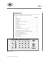
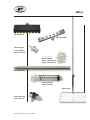
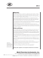
MPS-2
www.wpiinc.com
Multichannel Perfusion System
INSTRUCTION MANUAL
Serial No._____________________
100405
World Precision Instruments
MPS-2
Contents
Introduction........................................................................................ 1
Packing List........................................................................................ 2
General Warnings and Cautions......................................................... 4
Hardware Installation......................................................................... 4
MPS-2 Controller Operation................................................................ 6
START button.................................................................................................... 6
RESET button.................................................................................................... 6
MODE button.................................................................................................... 6
Manual Perfusion Mode.................................................................................... 6
Master Manual Perfusion Mode........................................................................ 7
On-line Perfusion Mode.................................................................................... 7
Off-line Perfusion Mode .................................................................................. 7
TTL Control Mode .......................................................................................... 7
Hardware Testing Procedure............................................................. 8
Software Installation and Operation.................................................. 9
Creating a New Perfusion Experiment.............................................................. 9
Saving Your Experimental Parameters........................................................... 12
Mode Selection............................................................................................... 12
Computer Perfusion Control Modes............................................................... 13
Cleaning............................................................................................ 14
Perfusion Trouble-shooting.............................................................. 15
Appendix........................................................................................... 16
Specifications................................................................................................. 16
Testing Drug Delivery..................................................................................... 16
Determining Flow Rate................................................................................... 17
Calculating Junction Volume.......................................................................... 18
Warranty............................................................................................ 19
Copyright © 2005 by World Precision Instruments, Inc. All rights reserved. No part of this publication
may be reproduced or translated into any language, in any form, without prior written permission of
World Precision Instruments, Inc.
World Precision Instruments
MPS-2
Introduction
The MPS-2 is a programmable 8-channel perfusion system designed for single
channel and whole-cell patch preparations. It offers the best combination of
performance and value. The MPS-2 incorporates the same high quality solenoid
valves found on similar but much more expensive systems. Unlike other perfusion
systems on the market, which often compromise performance to fit every possible
application, the MPS-2 is the only perfusion system designed and optimized
specifically for single-channel and whole-cell patch perfusion applications. The
MPS-2 is therefore the best perfusion system on the market for these specific
applications and is offered at a very attractive price.
The system can be controlled manually (i.e., via membrane switches on the
front panel) or through a PC. Two different manual control modes are offered.
One controls each channel independently and the other mode allows the user to
assign a master channel that will keep the system flowing when all other channels
are switched off. User-friendly timing software is included, and the programmed
perfusion sequence can be started by computer, a TTL trigger from an external
source such as a patch clamp amplifier, or manually by the user. The TTL control
mode that permits independent control of each valve by an external instrument or
data acquisition system.
The perfusion fluid flows through specially designed color-coded polyurethane
ribbon style tubing. The color-coding allows the user to easily trace each channel
for diagnostic or set up. The ribbon style of the tubing keeps the system very neat
and clean. Unlike PVC based tubing, polyurethane tubing contains no plasticizer,
which can cause contamination.
The most unique feature of the MPS-2 is its perfusion micro-manifold. Using the
latest microfluidic techniques, the injection molded micro-manifold provides the
least flow resistance and dead volume of any product on the market. The flow
channel inner diameter is approximately 1 mm, except for the last 5 mm before the
junction point. This design allows a fast flow rate without using a pressured system.
The maximum flow rates are 1 and 16 microliter per second for the 15 mm long
100 µm and 250 µm ID tips, respectively. Small channels and a unique design at
the merging point further reduce the chance of cross contamination. Dead volume
is less than 100 nL. The injection-molded micro-manifold is also designed as an
economical disposable item, eliminating problems of cross-contamination from
other experiments.
World Precision Instruments
MPS-2
Packing List
After unpacking, check the following items to make sure that all the perfusion
system parts have been received in a perfect condition.
Item
Quantities
MPS-2 Controller................................................................................. 1
Valve Console..................................................................................... 1
Syringe Holder.................................................................................... 1
Stand base and Stainless Steel Post.................................................. 1
Power Cord......................................................................................... 1
USB Cable.......................................................................................... 1
DB9-to-BNC 8-cable assembly.......................................................... 1
1 Amp Fuse......................................................................................... 2
10 mL Syringes................................................................................. 10
3-way Stopcock................................................................................ 10
Luer fitting with barb for 1/16” ID tubing........................................... 10
Color Coded Polyurethane Tubing Ribbon..................................... 5 ft.
Tubing for making micro-manifold cleaning adaptor.................... 3 in.
Micro-manifold Holding Rod............................................................... 1
Micro-manifold With 100 µm ID tip..................................................... 2
Micro-manifold With 250 µm ID tip..................................................... 2
User’s Manual..................................................................................... 1
Installation Software . ......................................................................... 1
MPS-2 controller
World Precision Instruments
MPS-2
Valve console
Syringe holders
Luer fitting for
1/16” ID tubing
(WPI #13156-100)
Micro-manifold
100 µm: (WPI #502110)
250 µm: (WPI #502125)
Manifold Holder
10 mL syringes
(WPI #3744-100)
Stand, post
3-way stopcock
(WPI #14057-10)
World Precision Instruments
MPS-2
General Warnings and Cautions
1.Read the user manual thoroughly before operating the MPS-2 multichannel perfusion system.
2. Before starting a formal experiment, perform several preliminary tests,
such as the drug interaction range test, to get familiar with this perfusion
system.
3.The 100 and 250 micron perfusion manifold tips are made of fine glass
capillary, which is subject to breakage and clogging. Handle the tip
carefully during the experiment.
4.Tubing must be removed gently so that the manifold is not damaged.
5. Any organic solvent, including alcohol, may damage the perfusion
manifold. If it is absolutely necessary to rinse the perfusion head with
alcohol, use ethyl alcohol only.
6. All the drug solutions should be filtered before use to prevent clogging of
the perfusion head.
7. After the experiment, the tubing system (especially the electromagnetic
valve, manifold and perfusion head) should be thoroughly washed with
fresh distilled water as soon as possible. Failure to do so may cause
damage to the system.
8.In case MPS-2 system does not work properly, stop the experiment
immediately. Switch off the power and go to the Troubleshooting section of
this manual.
Hardware Installation
1. Set the MPS-2 perfusion stand on a stable platform.
2.Insert the stainless steel post into the base and tighten the screw.
3.Loosen the screw on the back of the valve console and fix it onto the post.
Set the distance between the valve console center point and top of the
post to the desired height.
4. Fasten the syringe holder onto the post.
World Precision Instruments
MPS-2
5.Connect the valve console to the MPS-2 instrument with the cable
supplied.
6. Pull out of the plungers of the syringes and put the syringes into the
syringe holder.
7.Connect the 3-way stopcocks to the syringes.
8.Cut a 20 cm long section of the color-coded polyurethane tubing. Split it
to 8 individual tubes and put the luer fitting to one end. Connect the luer
fitting to the 3-way stopcock.
9.Connect the other ends of the eight tubes to the inputs of the valve
console.
10. Split one end of the long color-coded polyurethane tubing for about 15 cm.
Connect the splited end to the valve output port on the valve console.
11.Carefully connect the other ends of the polyurethane tubing to the micromanifold. In this step, the manifold should not be connected to the holding
rod. The female luer port may be damaged by the force applied to the
manifold when attaching the 8 ends of the tubing.
12.Connect the stainless holder rod to the micro-manifold. The end of the
holder rod is a male luer fitting. It can be pressed into the center hole of the
micro-manifold for a secure holding. Fix the holder to a micromanipulator.
We recommend WPI’s KITE-L for this purpose. It has sufficient precision
for the perfusion tip and an economical price. It has a left hand scale for
placing on the left side of the microscope, leaving the right side free for the
patch pipette.
13.Connect the MPS-2 to the computer’s USB port.
14.The DB9-to-BNC cable assembly connects to the control input port on the
back of the MPS-2.
World Precision Instruments
MPS-2
MPS-2 Controller Operation
The left section of
the MPS-2 front
panel contains the
“START”, “RESET”
and “MODE”
buttons, and three
functional indicator
LEDs:
START button
The button runs the perfusion process. In the “On-line” mode, it acts
as the
button and runs the experiment controlled by the perfusion
software. In “Off-line” mode, the “START” button will run the preset
perfusion parameters saved to the RAM of the control box from the computer.
RESET button
is the zero button for the micro-controller. It will stop any currently running
experiment, turn all channels off, and reset the mode to “Manual”. .
MODE button
rotates the perfusion mode between “Manual”,
“On-line”, “Off-line”, and “Master Manual”. Once
a mode is selected, the corresponding LED
will light up. In “Master Manual” mode, the “MANUAL”
LED blinks continuously. The operation of each mode is
described in the following sections.
World Precision Instruments
MPS-2
Manual Perfusion
Normal Mode
In this mode, the 8 channels are independently controlled by pressing the channel
buttons. When a channel is on, its LED lights up.
Master Channel Mode
This is just like the normal “Manual” mode except that only one channel can be
on at a time. If all other channels are turned off, channel 8 (the master channel)
automatically turns on. When this mode is first selected, it is in the inactive state in
which all channels are turned off. Press the channel 8 button to toggle between the
active and inactive state.
On-line Perfusion Mode
This is the computer software controlled mode. There are three ways to run
the perfusion experiment: by clicking the
(Run) button in the software, by
pressing the “START” button on the front panel, or by using the external triggered
TTL input. While an experiment is running from the computer, channels can also be
turned on and off by pressing the channel buttons.
Off-line Perfusion Mode
In this mode, the user can use “START” button or externally triggered TTL input
signal to start the perfusion program and perform the perfusion according to the
preset parameters saved in the control unit’s RAM from the computer. Note that
there is a delay of about 25 ms while the stored sequence is initialized. Perfusion
cannot be independently controlled with the channel buttons in this mode.
TTL Control Mode
Each channel is independently controlled by its own TTL input. The MPS-2 goes
into this mode when any one of the control inputs goes high (>2.0 V). While this
mode remains active, the “OFF-LINE” LED will blink continuously. The MODE
button is disabled, but RESET can still be used to close all open valves and
return to Manual mode. Press any of the Channel keys if the experiment has to be
manually halted. This will exit out of TTL Control mode and prevent it from going
back into that mode until RESET is pressed, or the instrument is turned off and on.
World Precision Instruments
MPS-2
Hardware Testing Procedure
In order to make sure the perfusion system works perfectly, the connection of
the tubing to all of the valves and connectors should be sealed tightly without
any leakage of the air pressure. In addition, there should not be any air bubbles
present inside the output of the tubes. Since the inner diameter of the tubing is so
small, if an air bubble is present inside the tubing the flow of solution will stop due
to blockage by air. Therefore, before the experiment, use the following procedure
(commonly referred to as priming) to check for air leakage and remove the bubbles
in the tubing:
1. Fill all the syringes with the distilled water and open the 3-way stopcock.
Check if there is any water leakage. If any, find out the proper reasons and
fix the leakage.
2.Turn on the power.
3.Turn on the first channel switch, until water droplets come out from the
micro-manifold tip.
4.During step 3, air bubbles might prevent the water droplets from coming
out of the tubing. To clear all air from the system, attach a syringe filled with
distilled water to the side port of the stopcock. Turn the stopcock knob so
that the syringe on the upper port is disconnected and push the air out
with the side port syringe. Repeat steps 3 and 4 for channels 2 to 8.
5.Carefully put on the micro-manifold. Turn on and off the channel switches
for channel 1 to 8, until the water droplets come out of the micro perfusion
head continuously
6.Determine the flow velocity at the micro perfusion head from each channel
by a stopwatch. Flow velocity for different channels should be about
the same. Otherwise, check the air leakage or residual bubbles in the
corresponding channel.
World Precision Instruments
MPS-2
Software Installation and Operation
System Requirements: Pentium II, Celeron or higher, or 100% supported CPU,
10Mb free hard drive space; CD-ROM or DVD-ROM driver.
Installation: Insert the CD into the CD-ROM. Run “Setup.exe” and the system will
automatically guide you through the installation procedure for the MPS-2 software.
The first time the MPS-2 is connected to the USB port of the computer, Windows
will automatically search for the driver for the new device. After the installation is
complete, you will see the MPS-2 listed in the Device Manager under “Universal
Serial Bus Controllers”.
Startup: The perfusion software can be found in the Start menu of Windows under
Programs\MPS-2. The software automatically connects to the MPS-2 on startup. If
the MPS-2 is plugged into the computer after the program has been loaded, press
the
button to establish a connection.
Creating a New Perfusion Experiment
The Experiment menu allows you to open a new or existing perfusion
experiment.
After clicking on “New Experiment”, two new windows will pop up to
allow the user to set the experimental parameters.
World Precision Instruments
MPS-2
Set the Experiment Time
The first step in creating a new experiment is to set the
(Total) Experiment Time.
The format is Hours:Minutes:Seconds:Milliseconds. If left
mouse key is held down over one of these fields, a double
arrow ( ) will appear and the value can be adjusted by
moving the mouse up or down. If you double click on a
field, the value can be entered directly with the keyboard.
Move to the next field by filling in both digits of the field or
by pressing the spacebar. Click Apply when all fields are set
to the desired values. The perfusion time below is set for 2
minutes.
Preset each channel’s perfusion time
Choose the desired channel by clicking on the box in front of
the channel name in the experiment window, or by clicking
on the channel number in the setup window. In this example,
we will be working with the 5th channel.
Press the Insert button on the bottom of the setup window to add a Start Time and
Stop Time. Click once on a start time or a stop time to select it. Once selected, the
values of its fields can be set the same way as the Experiment Time. If the “Time
Setup” option in the Mode Setup window (F3) is changed, then “Duration” will be
displayed instead of “Stop Time”.
World Precision Instruments
10
MPS-2
Press Insert again to add new rows. Once all times are entered for a channel,
click Apply to verify the changes. Otherwise, the new values will be lost when a
different channel is chosen or the Setup Window is closed.
The user can also set the perfusion time by holding the left mouse
key, moving to the right position and releasing the key. The precise
time at the mouse position is displayed at the right hand side of
the status bar at the bottom of the screen.
After the parameters have been successfully set, the program interface will be
shown as below. Follow the same procedure to finish the rest of the channel
programming.
World Precision Instruments
11
MPS-2
Saving Your Experimental Parameters
Select “Save As” in the Experiment menu. This will make a second window pop up.
Select the file name and saving folder to save the file. The user can also use the
system default file name,
which is made of 12 digital
numbers to indicate the
year, month, day, hour,
minute and second. In the
window below, the user
saved the file name at
3/22/2004 15:02:35.
Mode Selection
In order to change the operation mode or choose the serial port, click “Mode
Setup” in the Operation menu, press the F3 function key, or click the
button
in the Tool Box. A
window will pop up
as follows. Click on
the desired mode and
press OK to activate
it.
World Precision Instruments
12
MPS-2
“Manual Mode”, “On-line Mode”, “Off-line Mode”, and “Master Manual Mode” are
settings for the MPS-2 electronic unit. When a mode is chosen, the appropriate
LED will light up on its front panel. “Master Manual Mode” will make the “MANUAL”
LED blink continuously. The “Time Setup” option toggles the time entry mode of the
“Setup” window from Start Time / End Time to Start Time / Duration.
The modes can also be viewed and selected with the following
icons located on the Toolbar. From left to right, these icons
represent “Manual Mode”, “On-line Mode”, “Off-line Mode”, and “Master Manual
Mode”.
Computer Perfusion Control Modes
On-line Mode
In this mode, perfusion is controlled by the computer software in real time. “Run”,
“Pause”, and “Stop” can be controlled from the “Operation” menu, the Toolbar
icons
, or with the function keys (F8, F9, and F10 as shown on the
“Operation” menu).
Data Download Mode
The experimental procedure created with the software is downloaded into the RAM
of the MPS-2 control box when you press the button or select “Download” from the
Operation menu. The “On-line” LED on the MPS-2 control box will blink while the
program is being transferred.
World Precision Instruments
13
MPS-2
Cleaning
Clean the tubing system before and after each experiment. The residual drugs
will affect the accuracy of subsequent experiments. The electromagnetic valve
contains stainless steel components that are exposed to the perfusion solution.
Almost all of the perfusion solutions are electrolytes that can corrode stainless steel
with time. Therefore, it is very important to flush the valves with distilled water
and drain the water out afterwards. The protocols for cleaning are as follows:
1.Remove the perfusion micro-manifold from the holding rod.
2.Carefully remove each of the 8 pieces of tubing from the adaptors on the
back of the manifold. It is best to push them from their ends since pulling
them off off may damage the perfustion manifold. Pressurizing the tubing
may facilitate this procedure.
3.Turn on the control switches and discharge the drug solutions from all 8
tubing channels.
4. Keeping the switches open, fill each syringe with distilled water to wash
the tubing and valves. Repeat this step 2 to 3 times.
5. After the manifold is removed from the tubing (see step 2), press the
provided cleaning adaptor onto the manifold from the tip end. Connect it
to a syringe filled with filtered water and flush it. Note: Unfiltered water
could clog the manifold and permanently damage it. The manifold is made
of PMMA material. It can only be washed with water. Any organic solvent,
even alcohol, can permanently damage it. If alcohol must be used, only
use ethyl alcohol.
World Precision Instruments
14
MPS-2
Perfusion Trouble-shooting
If there is no perfusion, check the following to locate the problem:
1. You can tell if the perfusion controller is running a perfusion sequence
by looking at the lights above the numbered manual control buttons.
When a valve is being opened, the corresponding light should turn on.
If the perfusion controller won’t turn on at all, check the power cord
and the fuse in the back panel. If there is trouble communicating with
the computer in on-line mode, make sure the serial cable is tight and
try restarting both the instrument and the PC software.
2.The lights above each channel of the valve console turn on when the
valve is opened. In addition, there a soft click when a valve is turned
on or off. If the valve console is not responding, tighten the cable that
connects it to the perfusion controller.
3. Make sure the stopcock is in the correct position. The middle
pertrusion on the knob should be facing away from the syringe fluid
port on the side.
4. Visually check for air bubbles or obstructions in any segments of
tubing. Test the micro-manifold by connecting a syringe directly to one
of its input passages with a piece of tubing. If water flows through the
micro-manifold and valve console separately, try raising the syringe
holder or shortening the manifold output tubing.
5.The MPS-2 system is designed to work with aqueous solutions. Fluids
that are more viscous than water might not flow through the micromanifold.
World Precision Instruments
15
MPS-2
Appendix
Specifications
Base......................................................... White plastic over metal
Number of Perfusion Channels................ 8
I.D. of Micro-perfusion Head Tubing....... MP-1 100 µm; MP-2 250 µm
Dead Volume for Perfusion Head............ <100 nL
TTL Inputs................................................ High: > 2.0 V; Low: < 0.8 V
Packing Weight........................................ <8 kg
Packing Volume....................................... 680x210x170 mm
Testing Drug Delivery
The drug perfusion area of the MPS-2 series can cover the whole view field of a
200X microscope (objective 20X, eyepiece 10X). However, in order to perform
the experiments in an effective and reliable way, we suggest several preliminary
experiments as a control result. The following procedure uses patch clamp as an
example.
1.Clean the tubing system with distilled water. For details see Section 8.
2. Fill channel 1 with 150 mM filtered NaCl solution. Fill the other channels
with distilled water. Check up the system (bubble and flow velocity) as
previously described in Section 7.
3. Fill the culture dish with NaCl solution, and place it on the microscope
stage
4. Adjust the position of the perfusion head by micromanipulator, so that
the tip of the micro perfusion head is close to the bottom of the dish. The
access angle is about 35-45°.
5. Pull a 1 µm micropipette. Fill the pipette with 150 mM NaCl solution to
make it a microelectrode, and connect it to a patch clamp amplifier. Use
the electrode micromanipulator to position the tip of the electrode right in
front of the perfusion head at the bottom of the glass dish.
6. Apply a 5-10 mV voltage between the microelectrode and reference
electrode, and an electric current can be observed passing the electrode.
World Precision Instruments
16
MPS-2
Turning on any of the distilled water filled channels should cause a rapid
decrease of electric current to zero. Turning off the distilled water and
turning on channel 1 will bring the electric current back up to its original
level. Test the rest of the channels and the results should be the same.
7.If the electrode current does not reduce to zero, adjust the position and
direction of the perfusion head and electrode, and repeat step 6. After
several tests, you will get an idea about the right position and direction of
the perfusion head, cell, and electrode.
8. After the test, clean the entire tubing system.
9. For a formal experiment, the drug perfusion procedures are almost
the same as above, except that the NaCl solution is replaced by drug
solutions, and only the optimal positions for perfusion head, cell and
electrodes are used.
Determining Flow Rate
Theoretical Calculation
The relationship of flow rate to the height of the liquid column and inner diameter
of the capillary tubing can be accurately predicted with the Hagen-Poiseuille
equation.
F = C (d4 P V / L)
Where F is the flow rate in µL/min, P is the pressure in mm H2O, L is the length of
capillary tubing in mm, V is the viscosity of the perfusion media in cps, d is the
diameter of the capillary tubing in micrometers (µm), and C is a constant (1.3765
x10-8).
In most biological systems, the fluid has approximately the same density as
pure water, so P is equal to the height of the liquid column in mm. The viscosity
of most biological perfusion solutions can be considered as one. Since the flow
is proportional to the fourth power of the tubing diameter, the restriction of the
plastic tubing to the flow can be ignored. We only need to consider the diameters
and lengths of the quartz tubing, and the fluid passages leading up to the 8 to 1
junction. A good approximation of the resistance of the junction can be obtained
by removing the tubing from one of the 8 manifold inputs, and turning on one of the
other channels. Take the calculated flow resistance and divide it by two.
World Precision Instruments
17
MPS-2
Experimental Procedure
Place a dish filled with water on an analytical grade balance. Hang the micromanifold on the balance frame so that only the tip is touching the fluid in the dish.
Record the weight increase from the balance read out. Use distilled water so
that the specific gravity is easier to determine. Put the tip underneath the fluid
surface so that the surface tension will not affect the flow. It is a good idea to put
several small containers filled with water inside the analytical balance sample
compartment so that the humidity is high, thus reducing error due to evaporation of
the perfused water.
Our experiments with five different tubing sizes and different lengths have shown
that the error of using this equation to describe the flow is less than 5% (n=20).
Calculating Junction Volume
Set up the experiment for testing drug delivery (page 16). Use a patch clamp
amplifier with an analog output and control the MPS-2 with external TTL signals
(see “TTL Control Mode” on page 7). Simultaneously turn off the flow of KCl
solution and turn on a channel with distilled water. Record the electrical current
along with one of the TTL control signals on a chart recorder or other data
acquisition system. The response time of the system is determined by how long it
takes for the current to drop to zero once the distilled water is turned on.
Measure the length of the output tubing from the flat disk shaped surface of the
manifold body and add .5 mm to this value. If we have 100 micron tubing and the
length is 14.5 mm + 0.5 mm = 15 mm. The total volume of the tubing is Length × p
× r2 = 15 mm × 3.14159 × .052 = 0.118 mL.
Suppose the experimentally determined flow rate (see the experimental procedure
section of “Determining Flow Rate”) is 0.1 g/116 second × 1000 mL/g = 0.862
mL/second and the response time is 0.18 seconds. The total dead volume is 0.862
mL/second × 0.18 seconds = 0.155 mL. If we subtract the volume of the output
tubing we get 155 nL - 0.118 nL = 37 nL dead volume in the junction between the
eight fluid channels.
World Precision Instruments
18
MPS-2
Warranty
WPI (World Precision Instruments, Inc.) warrants to the original purchaser that this equipment, including its
components and parts, shall be free from defects in material and workmanship for a period of one year* from
the date of receipt. WPI’s obligation under this warranty shall be limited to repair or replacement, at WPI’s
option, of the equipment or defective components or parts upon receipt thereof f.o.b. WPI, Sarasota, Florida
U.S.A. Return of a repaired instrument shall be f.o.b. Sarasota.
The above warranty is contingent upon normal usage and does not cover products which have been
modified without WPI’s approval or which have been subjected to unusual physical or electrical stress or on
which the original identification marks have been removed or altered. The above warranty will not apply if
adjustment, repair or parts replacement is required because of accident, neglect, misuse, failure of electric
power, air conditioning, humidity control, or causes other than normal and ordinary usage.
To the extent that any of its equipment is furnished by a manufacturer other than WPI, the foregoing warranty
shall be applicable only to the extent of the warranty furnished by such other manufacturer. This warranty will
not apply to appearance terms, such as knobs, handles, dials or the like.
WPI makes no warranty of any kind, express or implied or statutory, including without limitation any
warranties of merchantability and/or fitness for a particular purpose. WPI shall not be liable for any damages,
whether direct, indirect, special or consequential arising from a failure of this product to operate in the manner
desired by the user. WPI shall not be liable for any damage to data or property that may be caused directly or
indirectly by use of this product.
Claims and Returns
• Inspect all shipments upon receipt. Missing cartons or obvious damage to cartons should be noted on the
delivery receipt before signing. Concealed loss or damage should be reported at once to the carrier and
an inspection requested. All claims for shortage or damage must be made within 10 days after receipt of
shipment. Claims for lost shipments must be made within 30 days of invoice or other notification of shipment.
Please save damaged or pilfered cartons until claim settles. In some instances, photographic documentation
may be required. Some items are time sensitive; WPI assumes no extended warranty or any liability for use
beyond the date specified on the container.
• WPI cannot be held responsible for items damaged in shipment en route to us. Please enclose merchandise
in its original shipping container to avoid damage from handling. We recommend that you insure merchandise
when shipping. The customer is responsible for paying shipping expenses including adequate insurance on
all items returned.
• Do not return any goods to WPI without obtaining prior approval and instructions (RMA#) from our returns
department. Goods returned unauthorized or by collect freight may be refused. The RMA# must be clearly
displayed on the outside of the box, or the package will not be accepted. Please contact the RMA department
for a request form.
• Goods returned for repair must be reasonably clean and free of hazardous materials.
* Electrodes,
batteries and other
consumable parts are
warranted for 30 days
only from the date on
which the customer
receives these items.
• A handling fee is charged for goods returned for exchange or credit. This fee may add up to 25% of the sale
price depending on the condition of the item. Goods ordered in error are also subject to the handling fee.
• Equipment which was built as a special order cannot be returned.
• Always refer to the RMA# when contacting WPI to obtain a status of your returned item.
• For any other issues regarding a claim or return, please contact the RMA department
Warning: This equipment is not designed or intended for use on humans.
World Precision Instruments, Inc.
International Trade Center, 175 Sarasota Center Blvd., Sarasota FL 34240-9258
Tel: 941-371-1003 • Fax: 941-377-5428 • E-mail: [email protected]
19
World
Precision
UK: Astonbury
Farm Business
Centre •Instruments
Aston, Stevenage, Hertfordshire SG2 7EG • Tel: 01438-880025 • Fax: 01438-880026 • E-mail: [email protected]
Germany: Liegnitzer Str. 15, D-10999 Berlin • Tel: 030-6188845 • Fax: 030-6188670 • E-mail: [email protected]