1
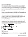
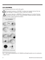
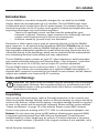
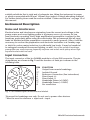
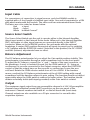
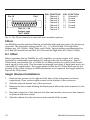
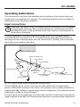
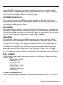
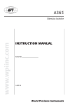
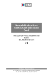
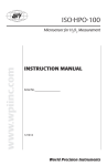
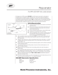
ISDB
www.wpiinc.com
ISO-DAM 8A and BRIDGE8
INSTRUCTION MANUAL
Serial No._____________________
030912
World Precision Instruments
BRIDGE8
ISDB
CONTENTS
BRIDGE8................................................................................................................................................. 1
Introduction..................................................................................................................................... 1
Unpacking................................................................................................................................... 2
Instrument Description................................................................................................................ 2
Operations........................................................................................................................................ 2
Positioning the Output to Zero............................................................................................ 3
Bridge Switch............................................................................................................................. 3
Transducer Calibration........................................................................................................... 4
Example....................................................................................................................................... 4
General Amplification............................................................................................................. 4
Specifications................................................................................................................................... 4
ISO-DAM8A............................................................................................................................................ 6
Introduction..................................................................................................................................... 7
Notes and Warnings............................................................................................................... 7
Unpacking................................................................................................................................... 7
Instrument Description................................................................................................................ 8
Noise and Interference........................................................................................................... 8
Input Connection...................................................................................................................... 8
Input Cable................................................................................................................................. 9
Source Select Switch................................................................................................................ 9
Balance Adjustment................................................................................................................ 9
Output.......................................................................................................................................... 9
Filters..........................................................................................................................................10
DC Offset...................................................................................................................................10
Single Channel Installation.................................................................................................10
Operating Instructions................................................................................................................11
Input Connections..................................................................................................................11
Output Connections..............................................................................................................12
Grounding.................................................................................................................................12
Shielding....................................................................................................................................12
Idle Settings..............................................................................................................................12
Control Adjustment...............................................................................................................12
Specifications.................................................................................................................................13
WARRANTY.........................................................................................................................................15
Claims and Returns.....................................................................................................................15
Repairs.............................................................................................................................................15
Copyright © 2012 by World Precision Instruments, Inc. All rights reserved. No part of this publication
may be reproduced or translated into any language, in any form, without prior written permission of
World Precision Instruments, Inc.
World Precision Instruments
iii
iv
World Precision Instruments
BRIDGE8
BRIDGE8
The following symbols are used in this guide:
This symbol indicates a CAUTION. Cautions warn against actions that can
cause damage to equipment. Please read these carefully.
This symbol indicates a WARNING. Warnings alert you to actions that can
cause personal injury or pose a physical threat. Please read these carefully.
NOTES and TIPS contain helpful information.
Fig. 1—Up to eight rackmountable ISO-DAM8A and Bridge8 modules can be combined in
a single chassis.
Introduction
Any combination of ISO-DAM8A or Bridge-8 modules may be combined in the same
instrument main frame. Bridge-8 includes a differential amplifier featuring high input
impedance, high common mode rejection of electrical interference and low current
leakage input terminals. Force, pressure, temperature, displacement, light and other
physical parameters are readily measured. Thermocouple wire transducers with cold
junction references for a wide range of temperature monitoring are also available.
World Precision Instruments
1
Each channel contains: a regulated DC power supply, 10V (+5 and –5V with respect
to signal ground) to provide DC power to transducers and a precision differential
amplifier with selectable voltage amplification and variable position adjustment control.
Each module includes a low pass filter with conditioner for strain gauges and other
transducers.
Unpacking
Upon receipt of this instrument, make a thorough inspection of the contents and
check for possible damage. Missing cartons or obvious damage to cartons should be
noted on the delivery receipt before signing. Concealed damage should be reported
at once to the carrier and an inspection requested. Please read the section entitled
“Claims and Returns” on page 15 of this manual. Please contact WPI Customer
Service if any parts are missing at 941.371.1003 or [email protected].
Returns: Do not return any goods to WPI without obtaining prior approval (RMA
# required) and instructions from WPI’s Returns Department. Goods returned
(unauthorized) by collect freight may be refused. If a return shipment is necessary,
use the original container, if possible. If the original container is not available, use a
suitable substitute that is rigid and of adequate size. Wrap the instrument in paper
or plastic surrounded with at least 100mm (four inches) of shock absorbing material.
For further details, please read the section entitled “Claims and Returns” on page
15 of this manual.
Instrument Description
Single Channel Installation
1. Remove two screws on the right and left sides of the instrument enclosure,
respectively. Then remove eight screws on the bottom of the enclosure.
2. Slide the internal chassis out of the enclosure.
3. Remove the two screws holding the blank panel where the new channel is to be
installed.
4. Plug the connector of this channel into the new module and then secure the
channel in position with two screws.
5. Slide the chassis into the enclosure and reinstall all screws.
Operations
Transducers are connected to Bridge-8 via the 8-pin transducer input connector on
the front panel. Spare 8-pin DIN plugs are provided with each instrument to allow
you to rewire the cables of other manufacturers’ transducers to connect to Bridge-8
modules (Fig. 2).
2
World Precision Instruments
BRIDGE8
+ O UT
-5V
2
4
+5V
1
NC
5
- O UT
3
8
NC
7
6
G ND
TRA NS DUCE R P L UG (S O L DE R S IDE)
S HIE L D
Fig. 2—Wiring schematic for the 8-pin DIN connection.
Positioning the Output to Zero
Insert the transducer plug into the panel transducer input connector. Switch the
Gain Select switch for the channel being used to x10 and set the Bridge switch
to Differential. Turn on the Power switch at the top of the panel. One or both of
the two red Offset Adjust indicator lamps will light if a transducer is plugged into
the appropriate connector on the front panel. Output coaxial connectors for all
channels are located on the rear panel of the instrument. If the – lamp is lit, the
output voltage level is minus. If the + lamp is lit, the output voltage level is positive.
To bring the output voltage level to nearly zero volts, adjust the Offset Adjust knob
above the Gain switch so that both lamps are lit together. A significant increase in
the sharpness or resolution of the zero adjustment may be achieved by increasing
the gain to x100.
Bridge Switch
Many transducers configured as Wheatstone bridges with four resistive elements will
directly access the differential amplifier, as represented in Fig. 3. When the Bridge
switch is in the Differential position, both inputs of the differential amplifier, inverting
and non-inverting, are connected to the signal terminals of the transducer bridge. In
single-ended operation, the inverting input of the differential amplifier is connected
to a variable reference potential leaving the non-inverting input available to the
signal source. In the Gnd (ground) position both the inverting and the non-inverting
inputs are connected to ground.
1
+ out
2
3
+5 v
+
- out
4
SHIELD
-5 v
Fig. 3—This transducer is configured as a Wheatstone bridge with four resistive elements.
World Precision Instruments
3
Transducer Calibration
Bridge-8 provides fixed and accurate decade amplification steps. Of most interest
to the user, however, may be the conversion factor from the physical variable—
grams, mm of Hg, mm of displacement—to output voltage. Since the transducer’s
conversion factor is often not exactly known and varies with the voltage applied to
the sensor (10 volts from Bridge-8), it is therefore necessary for the user to calibrate
the system using known forces, pressures or displacements to scale the output of
Bridge-8 quantitatively with the original physical parameter being measured.
Example
A typical pressure transducer is nominally rated at 5 microvolts out per volt of
excitation per mm of Hg. To compute the approximate output from Bridge-8 for this
transducer:
5 µV/V • 10 V • Amplification = 0utput µV per mm Hg
Thus, if we had selected x100 Amplification, the output per mm Hg would be
approximately 5 mV per mm Hg. Since the nominal rating of 5 µV per volt is usually
not exact, the user must, in the end, calibrate the transducer with a known hydrostatic
pressure to obtain an accurate conversion factor. (WPl’s model PM015 Pressure
Monitor/Calibrator is a suitable hydrostatic pressure calibration device.)
General Amplification
For transducer types other than resistive bridges, such as active transistor circuits,
magnetic, photocell or piezoelectric devices, the instrument’s differential amplifier
may still be used for signal amplification in differential and single-ended modes.
Note that pin 7, instrument ground, must be connected to the circuit ground of the
input source to achieve effective amplification. Careful shielding of signal generating
devices will result in lower noise “pickup” by the signal input wiring.
+5
-5
ext.
sig.
source
3
2
7
+
signal gnd
SHIELD
Fig. 4—
Specifications
Voltage Amplification ................................. x1, x10, x50, x100, x500, x1000 & adjustable
Input Impedance ..................................................................................................................... > 1012Ω
Input Leakage Current .................................................................................< 0.1pA at 25°C, typ.
4
World Precision Instruments
BRIDGE8
Voltage Offset Adjustment ............................................................. ± 50mV (low offset range),.
...............................................................................................................± 100mV (high offset range)
Amplifier Output Voltage ............................................................................ ± 5.0V (10mA, max.)
Transducer Excitation .....................................................................10V (± 5.0V) (100mA, max.)
Low Pass Filter Band (kHz) ..................................... 0.03, 0.1, 0.3, 1, 5, 10, and “wide band”
Enclosure Dimensions................................................................ 7 x 17 x 9.2˝ (18 x 43 x 23cm)
World Precision Instruments
5
ISO-DAM8A
The following symbols are used in this guide:
This symbol indicates a CAUTION. Cautions warn against actions that can
cause damage to equipment. Please read these carefully.
This symbol indicates a WARNING. Warnings alert you to actions that can
cause personal injury or pose a physical threat. Please read these carefully.
NOTES and TIPS contain helpful information.
Fig. 1—Up to eight rackmountable ISO-DAM8A and Bridge8 modules can be combined in
a single chassis.
6
World Precision Instruments
ISO-DAM8A
Introduction
The Iso-DAM8A is a modular bioamplifer designed for use with the Iso-DAM8
chassis, which can accommodate up to 8 modules. The Iso-DAM8A input stage
is differential and is isolated from the AC power system. For example, there is no
electrical connection to the AC power circuit ground. Isolated pre-amplification has
important advantages over non-isolated amplifiers:
• There is no significant current can flow from the preamplifier input
terminals to ground. Therefore, input connectors are intrinsically safe and
cannot cause electrical shock at the site of measurement.
• Problems caused by “ground loops” are eliminated.
Electrodes or other signal sources may be connected directly to the Iso-DAM8A
input connector, or an optional active headstage (WPI Part #74040) may be used.
The headstage connects to the Iso-DAM8A through a 5-foot cable. It contains a
high impedance differential amplifier in a small metal housing. Electrodes may be
connected directly to the headstage, which can be positioned at the measurement
site, minimizing electrical noise pickup and stray capacitance.
The Iso-DAM8A module contains an input DC offset adjustment, switch-selectable
gain, switch-selectable high pass and low pass filters, a line frequency “notch filter”
(which can be set to 50 or 60 Hz), and an output DC position adjustment.
The Iso-DAM8 chassis can be ordered for either 110-120VAC or 220-240VAC
operation. The chassis can accommodate up to eight Iso-DAM8A bioamplifiers. A
separate BNC connector is provided for the output of each channel, and all channel
outputs are available at a common DB-25 connector.
Notes and Warnings
CAUTION: The inputs to the Iso-DAM8A and the headstage can be damaged
by electrostatic discharge. We recommend that you momentarily touch the
Iso-DAM8A chassis or any grounded metal object before connecting wire or
electrodes to the inputs.
Unpacking
Upon receipt of this instrument, make a thorough inspection of the contents and
check for possible damage. Missing cartons or obvious damage to cartons should be
noted on the delivery receipt before signing. Concealed damage should be reported
at once to the carrier and an inspection requested. Please read the section entitled
“Claims and Returns” on page 15 of this manual. Please contact WPI Customer
Service if any parts are missing at 941.371.1003 or [email protected].
Returns: Do not return any goods to WPI without obtaining prior approval (RMA
# required) and instructions from WPI’s Returns Department. Goods returned
(unauthorized) by collect freight may be refused. If a return shipment is necessary,
use the original container, if possible. If the original container is not available, use a
World Precision Instruments
7
suitable substitute that is rigid and of adequate size. Wrap the instrument in paper
or plastic surrounded with at least 100mm (four inches) of shock absorbing material.
For further details, please read the section entitled “Claims and Returns” on page 15 of
this manual.
Instrument Description
Noise and Interference
Electrical noise and interference originating from the current and voltage in the
power mains and room lighting power is a primary source of concern for low
level bioelectric recording. Every high amplification preamplifier is subject to this
handicap, particularly when using microelectrodes. We recommend that all input
leads be shielded and the preparation connected to earth (ground). Often, it will be
necessary to enclose the preparation and electrode lead wires in a Faraday cage
or shield to reduce mains induction to sufficiently low levels. It may be beneficial
to extinguish overhead fluorescent lighting, as well. Use of the optional headstage
preamplifier can vastly improve frequency response and reduce noise pickup when highimpedance electrodes are used!
Input Connection
The input connector of the Iso-DAM8A module is a 8-pin DIN connector. The pin
designations are shown in Fig. 2 and the function of each pin is shown in the
following table.
PINFUNCTION
1
Output from remote headstage.
2** Isolated Ground
3
Reference Connection (See instructions)
4
Direct Input (+)
5
Direct Input (–)
6*
Headstage Power (+10VDC)
7*
Headstage Power (–10VDC)
8
No connection
Fig. 2—Iso-DAM8A input connections are labeled.
*Reserved for headstage use only. Do not use to power other devices.
**Must be used to reference + input and – input.
8
World Precision Instruments
ISO-DAM8A
Input Cable
For convenience of connection to signal sources, each Iso-DAM8A module is
supplied with a 5-foot length of shielded input cable. One end is terminated in a DIN
plug which mates with the module. The other end has unterminated tinned leads.
The wires are color-coded as shown below:
Red
+ Input
Black – Input
White Isolated Ground””
Source Select Switch
The Source Select Switch sets the unit to operate either in the Internal Amplifier
(direct input mode) or the External Probe mode. When set to the Internal Amplifier
(INT), electrodes or other signal sources are connected directly to the INPUT
connector. When set to the PROBE position, the unit works with the optional
headstage. A center GND position disconnects all inputs to permit you to establish
a DC baseline with the POSITION control. Note that in this position, the DC OFFSET
and BAL (balance) adjustments have no effect.
Balance Adjustment
The DC balance potentiometer let you adjust the Gain switch position stability. This
potentiometer is accessible through a small screwdriver hole on the front panel.
To adjust the DC balance, connect the “+” and “-” inputs of the input connector, or
the headstage, if used, to Isolated Ground. Set the GAIN switch to 10. Using an
oscilloscope or recorder connected to the Output connector, adjust the POSITION
control so that the output trace on the recorder or oscilloscope is near the zero
volt level. Rotate the GAIN selector switch from x10 to x10000. If the baseline
moves, readjust the DC Balance potentiometer at the x10000 setting with a small
screwdriver until the baseline returns its prior setting. The baseline should not deflect
appreciably when the GAIN switch is reduced to lower values. The baseline should
remain essentially stable (with input grounded) as the Gain switch is rotated.
Output
The maximum signal output from any preamplifier channel is ±10V. All preamplifier
channels have individual coaxial (BNC) connectors on the rear panel of the
instrument. Channel numbers start with #1 on the left hand side (front view).
Channel outputs are also available on a 25-pin connector for use with data
acquisition systems.
World Precision Instruments
9
Pin 13
Pin 1
Pins 14 ~ 25
(bottom row)
NOT USED
PINFUNCTION
1 Channel 1
2 Channel 2
3 Channel 3
4 Channel 4
5 Channel 5
6 Channel 6
7 Channel 7
PIN FUNCTION
8
Channel 8
9
Ground
10 Ground
11 Ground
12 Ground
13 Ground
Fig. 3—The 25-pin connector is used with data acquisition systems.
Filters
Iso-DAM8A provides selected filtering at both the high and low ends of its frequency
spectrum. The Low Filter settings are DC, 0.1, 1, 10 and 300Hz. The High Filter
settings are 100, 500Hz, 1kHz, 3kHz, and 10kHz. Typical settings recommended for
ECG and EEG would be Low Filter at 0.1Hz and the High Filter at 0.1kHz (100Hz).
DC Offset
When operating the Iso-DAM8A as a DC amplifier, you may require a DC offset
potential to compensate any existing DC voltage from the recording site. The DC
Offset knob can provide 0 to >100mV DC of either polarity to reduce (null) the net
input signal to zero volts. This becomes increasingly necessary if high gains are to be
used with DC amplification. The toggle switch below the DC Offset knob selects the
polarity of the offset voltage. If offset adjustment is not required, the toggle switch is
kept in the Off position.
Single Channel Installation
1. Remove two screws on the right and left sides of the instrument enclosure,
respectively. Then remove eight screws on the bottom of the enclosure.
2. Slide the internal chassis out of the enclosure.
3. Remove the two screws holding the blank panel where the new channel is to be
installed.
4. Plug the connector of this channel into the new module, and secure the channel
in position with two screws.
5. Slide the chassis into the enclosure and reinstall all the screws.
10
World Precision Instruments
ISO-DAM8A
Operating Instructions
The connection to and from the amplifier and the settings of the controls will vary
greatly from one application to another. The following guidelines may be helpful in
establishing initial operating conditions.
Input Connections
CAUTION: The inputs to the Iso-DAM8A and the headstage can be damaged
by electrostatic discharge. We recommend that you momentarily touch the
Iso-DAM8A chassis or any grounded metal object before connecting wire or
electrodes to the inputs.
It is very important to minimize input lead length, and use of shielded cable is
recommended for any leads over 2 or 3 inches (except grounding leads). Both the
inverting and non-inverting inputs must be connected. A “floating” (non-connected)
input will cause amplifier saturation.
DAM50, DAM60, DAM70
#3294 Grounding Clip
#5489 Probe
A
B
#2033 Adapter
Micromanipulator
#5469 Metal
Microelectrode
Adapter
Metal Microelectrode
(i.e., TM33B01)
Prep
EP2
Ag/AgCl Half Cell
Central Ground
Fig. 4—A typical single-ended configuration is shown here.
The Iso-DAM8A inputs can be connected in either differential or single-ended
modes. Differential connection can reduce noise pickup, and is usually preferable to
single-ended. Fig. 4 shows a typical single-ended configuration. The optional remote
headstage is shown in these examples.
The two inputs on the headstage are electrically identical, except that positive-going
signals applied to the RED non-inverting input produce a positive-going output from
World Precision Instruments
11
the Iso-DAM8A, whereas a positive-going signal applied to the BLACK inverting
input produces a negative-going output. The same holds true for the non-inverting
“+” input and inverting “–” input on the INPUT connector. Reversing the connections
from that shown simply results in an inverted signal.
Output Connections
The output from each Iso-DAM8A module is available on the rear panel from a
standard BNC connector or all channels are available at the 25-pin connector. See
Fig. 3 for pin designations. The Iso-DAM8A output is suitable for application to any
recording or data acquisition device.
Grounding
Proper grounding is critical to successful biological signal monitoring. The optimum
grounding configuration is the “single-point ground,” in which each component of a
monitoring setup is connected to a single point which is connected to earth or mains
ground. This grounding configuration is used in Fig. 3 and Fig. 4.
Shielding
The isolation feature of the Iso-DAM8A minimizes, but cannot eliminate, noise
pickup from electric distribution lines, fluorescent lights, computers, motors, radio
frequency transmitters, microwave ovens, etc. Use of shielded wires for input
connection is necessary if the subject is located more than a few inches from the
amplifier inputs. Even the use of shielded wires and proper grounding may be
insufficient in a high electrical noise environment, particularly if high impedance
electrodes are used, if the signal level is low (less than 100mV or so), or if high
frequency response is required. In these situations, the use of a metal shield, known
as a Faraday cage, which encloses the subject and the headstage may be necessary.
Idle Settings
If you are not certain what settings are required, the following settings are a good
starting point:
PROBE SELECT: GND
LOW FILTER: DC
DC OFFSET: OFF
GAIN: 10
HIGH FILTER: 10 kHZ
NOTCH FILTER: OFF
POSITION: Mid-range
POWER: OFF
Control Adjustment
After connecting inputs and outputs, the amplifier can be turned on. The POSITION
control may be used to establish a baseline setting on the recording device. It is
12
World Precision Instruments
ISO-DAM8A
normal to set this control so that the recording device indicates zero when the
PROBE SELECT is in the GND position. The PROBE SELECT switch should be set
appropriately for the setup.
• If the headstage is used, set the switch to PROBE.
• If direct connection is made to the Iso-DAM8A input, set the switch to INT.
The GAIN control should be set so that the desired signal produces a significant
(>30% of full scale or so) on the recording device. If the recording device has a gain
or sensitivity control, it is usually preferable to set the recording device to a low gain
and the Iso-DAM8A to a high gain.
The HIGH and LOW filters should be used to reject noise outside the signal
frequency range. If the signal is transient in nature and DC response is not required,
the LOW filter should be set to the highest setting that does not distort the signal.
The HIGH filter should be set to the lowest setting that does not distort the signal.
If line noise is a problem, the NOTCH FILTER may be set to 50 or 60Hz, as
appropriate for the power system. Use of the notch filter can severely distort some
signals.
If a large DC offset is present in the setup, the DC OFFSET control can be used to
cancel it. The setting of this control can be quite sensitive, especially at high gain
settings.
Specifications
This unit conforms to the following specifications:
Voltage Gain.........................................................................................x10, x100, x1000, x10,000
Input Impedance to Gnd, each input.............................. > 1012Ω DC, 5 picofarads (typical)
Input R, Between Inputs........................................................>1012Ω DC, 3 picofarads (typical)
Amp Noise, Input Shorted........................................................................< 0.2µV rms (1-100Hz),.
............................................................................................................................. < 1µV rms (1-10kHz)
Bandwidth..........................................................................................................................DC to 10kHz.
High Filter (Low Pass)....................................................................................... 0.1, 0.5, 1, 3, 10kHz
Low Filter (High Pass).............................................................................................0.1, 1, 10, 300Hz
Input Offset Voltage Adjust................................................................................................... ± 1VDC
Common Mode Rejection ...................................... > 100dB @ 50/60Hz with <10Ω source.
........................................................................................70dB typical with balanced 1MΩ source
Notch Filter Settings.................................................................................................50Hz, 60HZ, Off
Line Noise Rejection.................................................................................................................. >40dB
Output Voltage Swing............................................................................................ ±10V Maximum
Output Resistance..........................................................................................................................200Ω
Output Position Adjustment................................................................................................... ±1VDC
Power Source..........................................Power Adapter 110-120V/60Hz or 220-240/50Hz
Enclosure Dimensions.......................................................... 6.8 x 17 x 11.2˝ (17 x 43 x 28cm)
Shipping Weight ............................................................................................ 10–21 lb. (4.5–9.5kg)
World Precision Instruments
13
14
World Precision Instruments
ISO-DAM8A
WARRANTY
WPI (World Precision Instruments, Inc.) warrants to the original purchaser that this equipment,
including its components and parts, shall be free from defects in material and workmanship for a
period of one year* from the date of receipt. WPI’s obligation under this warranty shall be limited
to repair or replacement, at WPI’s option, of the equipment or defective components or parts upon
receipt thereof f.o.b. WPI, Sarasota, Florida U.S.A. Return of a repaired instrument shall be f.o.b.
Sarasota.
The above warranty is contingent upon normal usage and does not cover products which have been
modified without WPI’s approval or which have been subjected to unusual physical or electrical stress
or on which the original identification marks have been removed or altered. The above warranty will
not apply if adjustment, repair or parts replacement is required because of accident, neglect, misuse,
failure of electric power, air conditioning, humidity control, or causes other than normal and ordinary
usage.
To the extent that any of its equipment is furnished by a manufacturer other than WPI, the foregoing
warranty shall be applicable only to the extent of the warranty furnished by such other manufacturer.
This warranty will not apply to appearance terms, such as knobs, handles, dials or the like.
WPI makes no warranty of any kind, express or implied or statutory, including without limitation any
warranties of merchantability and/or fitness for a particular purpose. WPI shall not be liable for any
damages, whether direct, indirect, special or consequential arising from a failure of this product to
operate in the manner desired by the user. WPI shall not be liable for any damage to data or property
that may be caused directly or indirectly by use of this product.
Claims and Returns
Inspect all shipments upon receipt. Missing cartons or obvious damage to cartons should be noted
on the delivery receipt before signing. Concealed loss or damage should be reported at once to the
carrier and an inspection requested. All claims for shortage or damage must be made within ten
(10) days after receipt of shipment. Claims for lost shipments must be made within thirty (30) days
of receipt of invoice or other notification of shipment. Please save damaged or pilfered cartons until
claim is settled. In some instances, photographic documentation may be required. Some items are
time-sensitive; WPI assumes no extended warranty or any liability for use beyond the date specified
on the container
Do not return any goods to us without obtaining prior approval and instructions from our Returns
Department. Goods returned (unauthorized) by collect freight may be refused. Goods accepted for
restocking will be exchanged or credited to your WPI account. Goods returned which were ordered
by customers in error are subject to a 25% restocking charge. Equipment which was built as a special
order cannot be returned.
Repairs
Contact our Customer Service Department for assistance in the repair of apparatus. Do not return
goods until instructions have been received. Returned items must be securely packed to prevent
further damage in transit. The Customer is responsible for paying shipping expenses, including
adequate insurance on all items returned for repairs. Identification of the item(s) by model number,
name, as well as complete description of the difficulties experienced should be written on the repair
purchase order and on a tag attached to the item.
* Electrodes, batteries and other consumable parts are warranted for 30 days only from the date on which the
customer receives these items.
World Precision Instruments
15
World Precision Instruments, Inc.
USA
International Trade Center, 175 Sarasota Center Blvd., Sarasota FL 34240-9258
Tel: 941-371-1003 • Fax: 941-377-5428 • E-mail: [email protected]
UK
1 Hunting Gate, Hitchin, Hertfordshire SG4 0TJ
Tel: 44 (0)1462 424700 • Fax: 44 (0)1462 424701 • E-mail: [email protected]
Germany
Zossener Str. 55, 10961 Berlin
Tel: 030-6188845 • Fax: 030-6188670 • E-mail: [email protected]
China & Hong Kong
WPI Shanghai Trading Co., Ltd.
Rm 20a, No8 Dong Fang Rd., Lu Jia Zui Financial District, Shanghai PRC
Tel: +86 688 85517 • E-mail:[email protected]
Internet
www.wpiinc.com • store.wpiinc.com • www.wpichemistry.com
www.wpi-europe.com • www.wpiinc.cn
16
World Precision Instruments