1
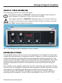
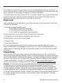
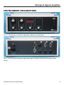
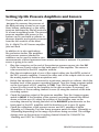
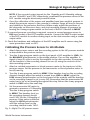
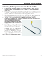
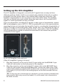
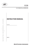
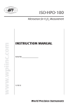
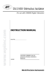
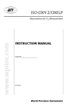
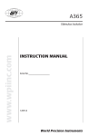
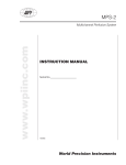
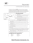
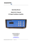
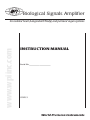
Biological Signals Amplifier
www.wpiinc.com
for isolated heart (Langendorff/Neely) and perfused organ systems
INSTRUCTION MANUAL
Serial No._____________________
070212
World Precision Instruments
Biological Signals Amplifier
CONTENTS
ABOUT THIS MANUAL...................................................................................................................... 1
INTRODUCTION .................................................................................................................................. 1
Parts List............................................................................................................................................ 2
Unpacking........................................................................................................................................ 2
INSTRUMENT DESCRIPTION........................................................................................................... 3
Setting Up HG Pressure Amplifiers and Sensors.................................................................. 4
Calibrating the Pressure Sensor to HG Module............................................................. 5
Setting up TH Thermometer Amplifier and Sensor............................................................ 6
Calibrating the Temperature Sensor to the TH Module.............................................. 7
Setting up the ECG Amplifier...................................................................................................... 8
WARRANTY.........................................................................................................................................11
Claims and Returns.....................................................................................................................11
Repairs.............................................................................................................................................11
Copyright © 2012 by World Precision Instruments, Inc. All rights reserved. No part of this publication
may be reproduced or translated into any language, in any form, without prior written permission of
World Precision Instruments, Inc.
World Precision Instruments
iii
iv
World Precision Instruments
Biological Signals Amplifier
ABOUT THIS MANUAL
The following symbols are used in this guide:
This symbol indicates a CAUTION. Cautions warn against actions that can
cause damage to equipment. Please read these carefully.
This symbol indicates a WARNING. Warnings alert you to actions that can
cause personal injury or pose a physical threat. Please read these carefully.
NOTES and TIPS contain helpful information.
Fig. 1—The Biological Signals Amplifier has four modules.
INTRODUCTION
This amplifier system and the sensors associated with it are designed to detect and
amplify perfusate pressures, temperature and ECG signals or surface potentials from
isolated perfused heart (Langendorff) and working heart (Neely) preparations. The
system can also be used to measure perfusion pressure and temperature from other
isolated organs, like kidney, liver and mesentery. In-vivo measurements of blood
pressures, temperature and ECG from animals can also be performed using this
system.
The modules in this amplifier system do not have selectable gain and filter controls,
because they are designed to work with data acquisition systems that have circuitry
and software for amplifying and filtering recorded data. If you require more
information about this amplifier and data recording systems that are capable of
working with this amplifier, contact WPI at [email protected] or 941.371.1003.
World Precision Instruments
1
The amplifier contains four modules: two for recording fluid pressures (perfusion or
aortic, pulse pressure or LVP), one for recording the temperature of the perfusate and
tissue, and one for recording ECG signals or surface potentials.
The main switch and fuses of the 220/110 V power supplies are located on the back
panel of each rack. Input and output sockets are also found on the back panels.
Operation switches and indicators are on the front panels.
Parts List
After unpacking, verify that there is no visible damage to the instrument. Verify that
all items are included:
(1) Biological Signal Amplifier with:
(2) HG AMP-02 pressure amplifiers
(1) TH AMP-06 temperature amplifier
(1) ECG AMP-03 biopotential signal amplifier
(2) Fluid pressure sensors with Canon (D-sub) 9-pin connectors
(1) Temperature sensor with microphone jack connector
(3) Microphone jack to BNC output cables
(1) Power cable
(1) Instruction Manual
ECG or biopotential electrode and lead cable are not included with this system.
Please contact WPI at [email protected] or 941.371.1003 to speak with one of our
representatives regarding the type of electrodes needed to record the biopotentials
of interest.
Unpacking
Upon receipt of this instrument, make a thorough inspection of the contents and
check for possible damage. Missing cartons or obvious damage to cartons should be
noted on the delivery receipt before signing. Concealed damage should be reported
at once to the carrier and an inspection requested. Please read the section entitled
“Claims and Returns” on page 11 of this manual. Please contact WPI Customer
Service if any parts are missing at 941.371.1003 or [email protected].
Returns: Do not return any goods to WPI without obtaining prior approval (RMA
# required) and instructions from WPI’s Returns Department. Goods returned
(unauthorized) by collect freight may be refused. If a return shipment is necessary,
use the original container, if possible. If the original container is not available, use a
suitable substitute that is rigid and of adequate size. Wrap the instrument in paper
or plastic surrounded with at least 100mm (four inches) of shock absorbing material.
For further details, please read the section entitled “Claims and Returns” on page
11 of this manual.
2
World Precision Instruments
Biological Signals Amplifier
INSTRUMENT DESCRIPTION
Fig. 2—The front panel has the operation switches and indicators.
Fig. 3—The back panel has the input and output sockets, along with the main power
switch.
World Precision Instruments
3
Setting Up HG Pressure Amplifiers and Sensors
The HG amplifier and its sensor are
designed to measure the pressure of
the fluid perfusing a heart or an organ
(liver, kidney, mesentery), or the aortic
pressure developed by the left ventricle
of a heart in working mode. The second
pressure amplifier and sensor in the
system can be used with a catheter to
measure diastolic and systolic pressures
from the left ventricle of the heart.
Fig. 4—(Right) The HG Pressure amplifier,
front and back.
In addition to in-vitro applications,
like perfusion studies, the amplifiers
and pressure sensors attached to
catheters can be used to make in-vivo
measurements of blood pressures from arteries and veins in animals. If a pressure
sensor is going to be used:
1. Plug the connector on the end of the perfusion pressure sensor into the IN1
9-pin Canon (D-sub) socket on the back panel of the amplifier. The sensor is
now connected to the HG1 amplifier module.
2. Plug the microphone jack of one of the output cables into the OUT1 socket of
the HG1 pressure amplifier. Connect the other end of the output cable to one of
the analog inputs of the data acquisition unit.
3. Before the transducer is connected to a perfusion cannula or catheter, check the
baseline level of the pressure recording channel. Turn the 4-way program switch
on the front panel of HG1 amplifier to GND. Turn ON the amplifier. A signal
of zero (0) volts is sent by the amplifier to the data recorder. If necessary, set
the baseline of the recording channel to zero (0) using the controls of the data
recording system.
4. Check the baseline output of the pressure amplifier. Turn the 4-way program
switch to MEAS. If the baseline of the pressure recording channel has shifted
above or below zero (0), adjust the position of the baseline seen on the
recording channel by turning the knob of the BALANCE potentiometer on the
front panel of the HG1 amplifier until the baseline is set to zero (0), again.
5. Check the calibration of the pressure sensor and HG1 amplifier at either
10mmHg or 100mmHg. Turn the 4-way program switch to either 10(mmHg) or
100(mmHg) depending on the range of pressures being recorded. The voltage
change seen on the pressure recording channel should be 100mVDC for
10mmHg and 1VDC for 100mmHG.
4
World Precision Instruments
Biological Signals Amplifier
NOTE: If the recorded output signals for the 10mmHg and 100mmHg settings
are not 100mVDC and 1VDC respectively, recalibrate the pressure sensor to the
HG1 module using the directions provided below.
6. Once the calibration of the sensor and amplifier have been verified, prepare to
attach the pressure sensor to the cannula or catheter. Purge all lines to remove
any bubbles in the perfusion fluid lines. When ready, adjust the positions of
the stopcocks on the sensor lines, and start recording changes in pressure by
turning the 4-way program switch on the front of the HG1 module to MEAS.
7. If a second pressure recording is required, connect a second pressure sensor to
IN2 input socket of the HG2 amplifier module. Connect the OUT2 output socket
of the HG2 module to another analog input on the data recorder using a similar
output cable.
8. Check the baselines and calibration of the HG2 amplifier and it sensor using the
same procedures used on HG1.
Calibrating the Pressure Sensor to HG Module
1. Attach the pressure sensor and the recording system to the HG pressure module
as described in the previous section.
2. Turn the 4-way program switch on the front panel of HG amplifier to GND. Set
the BALANCE potentiometer to the middle position. Turn on the amplifier. A
signal of zero (0) volts is sent by the amplifier to the data recorder. If necessary,
set the baseline of the recording channel to zero (0) using the controls of the
data recording system.
3. Attach a certified manometer or blood pressure meter to the input port of the
pressure sensor. Set the pressure in the manometer or blood pressure meter to
zero(0) mm Hg
4. Turn the 4-way program switch to MEAS. If the baseline level on the recording
channel changes when this switch is moved from GND to MEAS, adjust the
LOW trimmer-potentiometer on the front panel of the module until the baseline
on the recording channel is set to zero (00). Remember that the manometer/BP
meter has to be set at 0mmHg throughout this step. Return the 4-way program
switch to GND before the next step.
5. Set the manometer/BP meter to
generate a pressure of 100mmHg.
Turn the 4-way program switch
to MEAS. The baseline level on
the recording channel should
read 1VDC for the 100mmHg of
pressure. If the value is different,
adjust the HIGH potentiometer
until the voltage level on the
recording channel reads 1VDC.
Fig. 5—(Right) The HG pressure sensor.
World Precision Instruments
5
Setting up TH Thermometer Amplifier and Sensor
The TH amplifier and its sensor are designed to measure the temperature of the fluid
perfusing a heart or an organ (liver, kidney, mesentery) in order to determine the
temperature of the organ.
Fig. 6—The TH Temperature Amplifier, front and back.
If the temperature sensor is going to be used:
1. Plug the microphone jack on the end of the temperature sensor to the TH IN
socket on the back panel of the amplifier. The sensor is now connected to the
TH amplifier module.
2. Plug the microphone jack of one of the output cables into the TH OUT socket of
the TH pressure amplifier. Connect the other end of the output cable to one of
the analog inputs of the data acquisition unit.
3. Turn the 3-way program switch to GND. Place the temperature probe on or into
the area where the temperature needs to be measured. Turn on the amplifier
unit. The actual temperature of the area being monitored appears on the 3-digit
display on the front panel of the TH module.
4. Check the baseline level of the temperature recording channel. A signal of
zero (0) volts is sent by the amplifier to the data recorder. If necessary, set the
baseline of the recording channel to zero (0) using the controls of the data
recording system.
5. Turn the 3-way program switch to the 45ºC position. The voltage level on the
recording channel should change from 0 to 450mVDC corresponding to the
programmed 0-45ºC temperature range.
6. Turn the program switch to MEAS. The voltage level on the recording channel
should now correspond to the actual temperature at the location of the sensor.
6
World Precision Instruments
Biological Signals Amplifier
Calibrating the Temperature Sensor to the TH Module
1. In an insulated container, prepare 2–3L of water or fluid at about 20ºC. In a
second insulated container prepare 2–3L of water at a higher temperature,
about 40ºC.
2. Put a precision thermometer (0.1ºC) through the lid of each insulated container
so that the bulb of the thermometer is in the middle of the container. Leave an
opening on the lid of each container for the temperature sensor.
3. Place the temperature probe into the cooler fluid. Place the tip of the probe as
close to the bulb of the thermometer as possible without touching it.
4. Turn the 3-way program switch to the MEAS position. Wait until the
temperature reading on the TH module stabilizes. Then, read the temperature
on the thermometer. Set the 3-digit
display to the temperature of the
thermometer by adjusting the LOW
potentiometer on the front of the TH
module.
5. Repeat Steps 3 and 4 for the warmer
fluid in the other insulated container.
Since the temperature of the fluid
is warmer, adjust the 3-digit display
to read the temperature of the
warmer fluid by adjusting the HIGH
potentiometer. The TH module and
sensor is now set and calibrated for a
range of 20–45ºC.
Fig. 7—(Right) The TH temperature sensor.
World Precision Instruments
7
Setting up the ECG Amplifier
The ECG amplifier is designed to record the ECG signals from as many as three
different positions (leads I, II, III) on an animal using standard electrodes or surface
potentials from the muscle fibers of an isolated heart using wire electrodes. This
amplifier is appropriate for use on species in size from rats to dogs. The amplifier
also has an internal rate meter which allows the heart rate to be recorded as ECG
signals or surface potentials are also recorded.
If you are interested in recording ECG signals or other types of biopotentials, contact
WPI at [email protected] or 941.371.1003 to speak with one of our representatives
regarding the type of electrodes that would be best for recording the biopotentials of
interest. The type of electrodes (plate, pellet, needle, wire, etc.) determine the type of
lead wires needed to connect the electrodes to the input cable of the ECG amplifier,
and the preparation required to attach the electrodes to the animal and promote
conduction of the signal.
Fig. 8—ECG Amplifier, front and back.
If the ECG amplifier is going to be used:
1. Plug the connector on the end of the ECG input cable into the ECG-IN 15-pin
Canon (D-sub) socket on the back panel of the amplifier.
2. Plug the connector on the end of the ECG output cable to the ECG-OUT 9-pin
Canon (D-sub) socket below the ECG-IN socket. Connect the other ends of the
output cable, which are labeled with numbers that correspond to standard ECG
limb leads [I (1), II (2), III (3)] to the analog inputs on the data recorder that are
needed.
8
TIP: If only one pair of electrodes are needed to record a surface potential from
heart muscle, then only one of the leads (I, II, or III) needs to be connected to
the data recorder.
World Precision Instruments
Biological Signals Amplifier
3. Turn the 3-way program switch on the front panel of ECG amplifier to GND.
Turn on the amplifier. A signal of zero (0) volts is sent by the amplifier to the
data recorder. If necessary, set the baseline of the recording channel to zero (0)
using the controls of the data recording system.
4. Check the calibration of the recording channel. Turn the 3-way program
switch to 1mV. The signal on the recording channel should show a deflection
of 1mVDC, which is the nominal voltage used to calibrate ECG amplifiers. If
needed, use the unit conversion function of the data recording program to
make the 1mVDC signal from the ECG amplifier create a 1mv deflection on the
recording channel.
5. After the calibration check, turn the 3-way program switch to MEAS. Depending
on the sets of leads and electrodes that have been attached to the animal or
heart, ECG or biopotential signals should appear on the output device.
World Precision Instruments
9
10
World Precision Instruments
Biological Signals Amplifier
WARRANTY
WPI (World Precision Instruments, Inc.) warrants to the original purchaser that this equipment,
including its components and parts, shall be free from defects in material and workmanship for a
period of one year* from the date of receipt. WPI’s obligation under this warranty shall be limited
to repair or replacement, at WPI’s option, of the equipment or defective components or parts upon
receipt thereof f.o.b. WPI, Sarasota, Florida U.S.A. Return of a repaired instrument shall be f.o.b.
Sarasota.
The above warranty is contingent upon normal usage and does not cover products which have been
modified without WPI’s approval or which have been subjected to unusual physical or electrical stress
or on which the original identification marks have been removed or altered. The above warranty will
not apply if adjustment, repair or parts replacement is required because of accident, neglect, misuse,
failure of electric power, air conditioning, humidity control, or causes other than normal and ordinary
usage.
To the extent that any of its equipment is furnished by a manufacturer other than WPI, the foregoing
warranty shall be applicable only to the extent of the warranty furnished by such other manufacturer.
This warranty will not apply to appearance terms, such as knobs, handles, dials or the like.
WPI makes no warranty of any kind, express or implied or statutory, including without limitation any
warranties of merchantability and/or fitness for a particular purpose. WPI shall not be liable for any
damages, whether direct, indirect, special or consequential arising from a failure of this product to
operate in the manner desired by the user. WPI shall not be liable for any damage to data or property
that may be caused directly or indirectly by use of this product.
Claims and Returns
Inspect all shipments upon receipt. Missing cartons or obvious damage to cartons should be noted
on the delivery receipt before signing. Concealed loss or damage should be reported at once to the
carrier and an inspection requested. All claims for shortage or damage must be made within ten
(10) days after receipt of shipment. Claims for lost shipments must be made within thirty (30) days
of receipt of invoice or other notification of shipment. Please save damaged or pilfered cartons until
claim is settled. In some instances, photographic documentation may be required. Some items are
time-sensitive; WPI assumes no extended warranty or any liability for use beyond the date specified
on the container
Do not return any goods to us without obtaining prior approval and instructions from our Returns
Department. Goods returned (unauthorized) by collect freight may be refused. Goods accepted for
restocking will be exchanged or credited to your WPI account. Goods returned which were ordered
by customers in error are subject to a 25% restocking charge. Equipment which was built as a special
order cannot be returned.
Repairs
Contact our Customer Service Department for assistance in the repair of apparatus. Do not return
goods until instructions have been received. Returned items must be securely packed to prevent
further damage in transit. The Customer is responsible for paying shipping expenses, including
adequate insurance on all items returned for repairs. Identification of the item(s) by model number,
name, as well as complete description of the difficulties experienced should be written on the repair
purchase order and on a tag attached to the item.
* Electrodes, batteries and other consumable parts are warranted for 30 days only from the date on which the
customer receives these items.
World Precision Instruments
11
World Precision Instruments, Inc.
USA
International Trade Center, 175 Sarasota Center Blvd., Sarasota FL 34240-9258
Tel: 941-371-1003 • Fax: 941-377-5428 • E-mail: [email protected]
UK
1 Hunting Gate, Hitchin, Hertfordshire SG4 0TJ
Tel: 44 (0)1462 424700 • Fax: 44 (0)1462 424701 • E-mail: [email protected]
Germany
Zossener Str. 55, 10961 Berlin
Tel: 030-6188845 • Fax: 030-6188670 • E-mail: [email protected]
China & Hong Kong
WPI Shanghai Trading Co., Ltd.
Rm 20a, No8 Dong Fang Rd., Lu Jia Zui Financial District, Shanghai PRC
Tel: +86 688 85517 • E-mail:[email protected]
Internet
www.wpiinc.com • store.wpiinc.com • www.wpichemistry.com
www.wpi-europe.com • www.wpiinc.cn