1
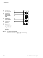
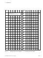
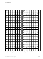
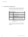
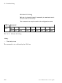
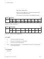
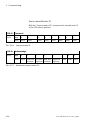
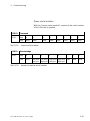
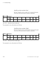
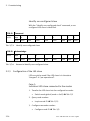
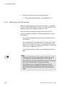
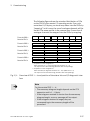
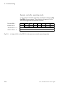
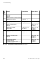
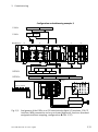
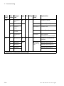
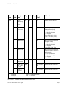
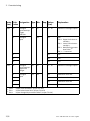
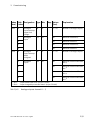
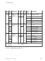
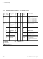
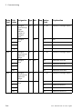
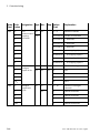
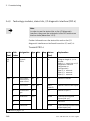
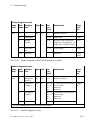
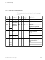
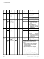
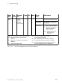
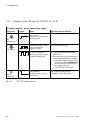
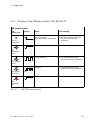
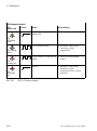
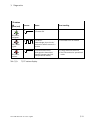
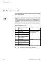
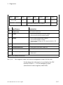
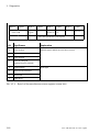
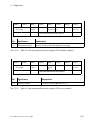
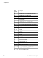
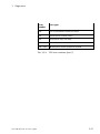
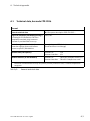
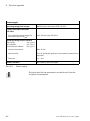
3. Diagnostics Byte 0 Byte 1 Error code Byte 2 Byte 3 Byte 4 Byte 5 Byte 6 Byte 7 Error re gister Status bits CPX module no. CPX error no. Reserved Additional error inf. Index 1001 Index 1002 (manufacturer status register) Bit Significance Explanation 0 Generic error Bit is set for each error 1 Current – Short circuit/overload in sensor supply – Short circuit/overload at the outputs 2 Voltage – UOUT (undervoltage at the outputs) – UVAL (undervoltage at valves) – Failure of load voltage at CPX output module or CPX input module 3 – – 4 Communication error – Node guard, heart beat, CAN error – – Manufacturer specific – Wire break – Other error 5…6 7 bold = Bit is used by CPX terminal Tab. 3/12: Error register (index 1001 with bit assignment as per CiA 301/401) Further diagnostic information is provided by the CPX terminal in bytes 3 ... 6 of the emergency object (manufacturer status register, index 1002). Festo P.BE-FB14-EN en 1411d English 3-17