1
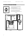
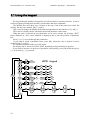
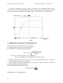
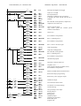
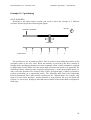
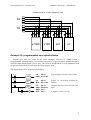
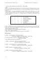
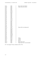
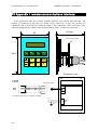
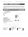
Parker Hannifin S.p.A. – Divisione S.B.C.
HPD25-67– High Power
User’s Manual
Pr19 calculation (peak current)
Pr19 MAX = Pr33 ⋅ 3
The maximum value must be no higher than three times the value of Pr33
Pr29 calculation (number of poles)
Use the following table for MB series motors
Flange ( mm )
105
145
205
Pr32 calculation (rated speed)
Pr29
8
8
8
If Pb 42.6=0
Pr32 = Vmax ⋅ 1.12
If Pb 42.6=1
Pr 32 =
where:
ω ⋅ VMAIN
VMOT
⋅ 8.3
ω is nominal motor speed in rad/sec
Vmain is HPD power supply in Vrms
Vmot is motor rated voltage in Vrms
Vmax is motor maximum used speed
Evaluation of Pr16 and Pr17 (speed regulator gain)
The default values of Pr16 and Pr17 have been chosen considering identical motor and
drive rated currents; if this is not the case correct the values of parameters Pr16 and Pr17
with the ratio of the motor rated current/drive rated current. Preventive execution of this
compensation will eliminate the risk of motor vibration at the first start-up.
6) Set the analogue reference signal to 0 V (terminals 1, 2 of board X2), and enable the
drive (24 V on terminal 11 of board X3 ).
7) The motor shaft must be stopped; when the analogue reference voltage is changed motor
speed should change proportionally. If this is not the case check your wiring.
8) Save your changes with b99.15.
The drive is preset with default values designed to meet the requirements of the majority of
applications. With the default values the pico-PLC in the drive runs the program described in
appendix G, so the following functions will be present on the input and output terminal
boards:
11
12
13
14
15
16
17
18
26
TERMINAL BOARD X2
real speed > Pr13
motor speed = reference (+/- 20 rpm)
real speed = 0
real speed > 0
motor thermal image active (i2t)
terminal A
terminal B
drive ready
(n.c. contact)
11
12
13
14
15
16
17
18
TERMINAL BOARD X3
drive enable
left limit-switch (n. c.)
right limit-switch (n. c.)
emergency stop (n. c.)
clockwise/counter-clockwise rotation
start / stop