1
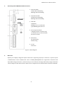
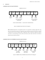
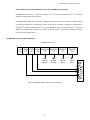
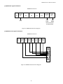
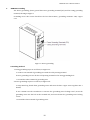
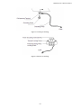
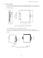
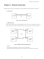
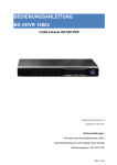
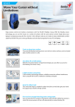
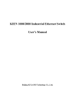
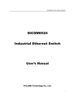
KOM200 User’s Manual 200911 KOM200 Industrial Serial to Fiber Media Converter User’s Manual KYLAND Technology Co., Ltd. 1 KOM200 User’s Manual 200911 Table of contents CHAPTER 1: PRODUCT OVERVIEW---------------- 3 CHAPTER 2: SPECIFICATIONS ---------------------- 4 CHAPTER 3: INSTALLATION ------------------------ 5 1. KOM200 SERIES LIST ----------------------------------------- 5 2. THE FRONT PANEL OF KOM200 MEDIA CONVERTER: -------- 6 3. FIBER PORT ---------------------------------------------------- 6 4. DATA PORTS --------------------------------------------------- 7 (1) KOM200-485/232L signals definition ------------ 7 (2) KOM200-485/232 and KOM200-485/232A signals definition (3) KOM200-232/422 signals definition ----------------- 8 (3) KOM200A signals definition ------------------------ 9 (4) KOM200-V.24 signals definition -------------------- 9 5. KOM200 GROUNDING -------------------------------------- 10 6. HARDWARE INSTALLATION ---------------------------------- 12 CHAPTER 4: NETWORK CONNECTION ----------- 13 2 7 KOM200 User’s Manual 200911 Chapter 1: Product Overview KOM200 serial to fiber media convertor allows RS232, RS485 and RS422 devices or networks to communicate over secure, noise immune, optically isolated, fiber optic cabling at extended distances as well convert RS232 to either RS485 or RS422 serial standards. It is industrial hardened and specially designed to operate reliably in electrically harsh and climatically demanding environments. KOM200 meets the requirements of the most strict international EMI and environmental standards for use in electric utility substations and factory floor applications. Its features are as below: 1. 1 x RS232 / 1 x V.24 / 1 x RS485/ 1x RS422 interface 2. Transparent Communication, plug & play 3. Special protection circuit for serial port, supports hot-swappable function 4. Integrated optical transceiver, reliable optical power output 5. Complete anti-electromagnetic interference, anti-earth loop interference, anti-thunder and lightning damage 6. DIN rail installation, rack bracket for rack mounting installation 7. Single fiber ring 3 KOM200 User’s Manual 200911 Chapter 2: Specifications 1. Bit Error Rate ≤10-10 2. Asynchronous rate 0 to 115.2Kbps (adaptive) 3. Electric characteristics Support RS232, RS422, RS485 standards; RS-485 port can be connected to 32-128 nodes with the transmission distance of 1200 meters 4. Physical interface 8 core terminal 5. Fiber transmission distance Multi-mode 2~5km, single-mode 40/80km 6. Fiber Connector FC/SC/ST 7. Power supply 24VDC (12~36VDC), 48VDC(36~72VDC), 110VDC (72~144VD), 110VAC/220VAC/220VDC (85~265VAC/120~370VDC) 8. Power consumption <3W 9. Relative humidity 0-95% (non-condensing) 10. Optical power output >-13dbm (single-mode system) >-20dbm (multi-mode system) 11. Receiving sensitivity <-28dbm (single-mode system) <-35dbm (multi-mode system) 12. Operating temperature -40℃~+85℃ 13. Storage temperature -40℃ ~+85℃ 14. Dimensions 36mm x 100mm x 75mm (W x H x D) 4 KOM200 User’s Manual 200911 Chapter 3: Installation 1. KOM200 series list Model Description KOM200-S-232/422 Single mode RS232/422 media converter ( 2-channel data, point to point) KOM200-M-232/422 Multi mode RS232/422 media converter ( 2-channel data, point to point) KOM200-S-485/232 Single mode RS485/232 media converter (3-channel data, point to point) KOM200-M-485/232 Multi mode RS485/232 media converter (3 -channel data, point to point) KOM200-S-485/232A Single mode RS485/232 media converter (The 2nd and 3rd channel multiplexing, point to point) KOM200-M-485/232A Multi mode RS485/232 media converter (The 2nd and 3rd channel multiplexing, point to point) KOM200-S-485/232L Single mode RS485/232 media converter (2-channel data, single fiber ring) KOM200-M-485/232L Multi mode RS485/232 media converter (2-channel data, single fiber ring) KOM200A-S-232 Single mode RS232 media converter (1-channel data, connected to RS232 fiber port) KOM200A-M-232 Multi mode RS232 media converter (1-channel data, connected to RS232 fiber port) KOM200-S-V.24 Single mode V.24 media converter KOM200-M-V.24 Multi mode V.24 media converter 5 KOM200 User’s Manual 200911 2. The front panel of KOM200 media converter: 1. Data Send LED: Off-No data transmitting Blinking-Data transmitting 2. Data Receive LED: Off-No data transmitting Blinking-Data transmitting 3. Run LED: ON-Master Blinking once a second-Slave Quick Blinking-Error Occurs 4. Power Input Terminal: V-Negative Power Connection (L) +V-Positive Power Connection (N) PG-Power Ground 5. Fiber Ports: TX-Transfering RX-Receiving 6. P1-P8: Data Ports Figure 1: Panel Diagram 3. Fiber Port Optical part employs integrated optical transceiver supporting FC/SC/ST connector. In point-to-point communication, 3-wire of RS232 and 7-wire of RS232/RS485/RS422 are supported to transmit serial data. While using the devices, connect the TX port of local device through multi mode/single mode fiber cable to RX port of the remote device. Please refer to chapter four for detail network connection methods. 6 KOM200 User’s Manual 200911 4. Data Ports (1) KOM200-485/232L signals definition KOM200 Data Ports GND P2 P1 Control Signal GND RS485- RS485+ P3 P4 User RS485- RXD1 P5 TXD1 P6 User RS485+ The Third Channel RS485 Data P1,P2 connected: Master; RXD0 P7 TXD0 P8 User TXD0 User RXD0 The First Channel RS232 Data P1,P2 are not connected: Slave Figure 2: KOM200-485/232L Interface Diagram Note: KOM200-485/232L is an upgraded model for the application requiring single fiber ring. Users can connect these units into a single fiber ring, and the data interface includes one channel of RS232 and one channel of RS485 without configuration. When composing a single fiber ring, the unit with its P1 and P2 being connected will be the Master, while others with their P1 and P2 not being connected will be the Slaves. (2) KOM200-485/232 and KOM200-485/232A signals definition KOM200 Data Ports P1 GND P2 RS485P3 RS485+ P4 GND User RS485- User RS485+ RXD1 P5 User TXD1 The third data RS485 TXD1 P6 RXD0 P7 User RXD1 User TXD0 The second data RS232 TXD0 P8 User RXD0 The first data RS232 Figure 3: KOM200-485/232 KOM200-485/232A Interface Diagram 7 KOM200 User’s Manual 200911 Notes: Differences between KOM200-485/232 and KOM200-485/232A: In KOM200-485/232, the 1st channel of RS232, the 2nd channel of RS232 and the 3rd channel of RS485 are independent to each other; In KOM200-485/232A, the 1st channel of RS232 is independent, the 2nd channel of RS232 and the 3rd channel of RS485 are multiplexing, which means the 2nd channel of RS232 can communicate with the 2nd channel of RS232 and 3rd channel of RS485 in another device, and the 3rd channel of RS485 can communicate with the 2nd channel of RS232 and the 3rd channel of RS485 in another device without configuration. (3) KOM200-232/422 signals definition KOM200 Data Ports LCS GND P1 P2 TXD P3 RXD RS422R+ RS422RP4 P5 P6 User RS422 Receive+ User RS422 Receive- RS422TP7 User RS422 Send- RS422T+ P8 User RS422 Send+ 8 6 7 8 9 1 2 3 4 5 Figure 4: KOM200-RS232/422 Interface Diagram KOM200 User’s Manual 200911 (3) KOM200A signals definition KOM200 Data Ports P1 GND P2 P3 P4 P5 P6 RXD0 P7 TXD0 P8 User User TXD0 RXD0 The first channel of RS232 Data GND Figure 5: KOM200A Interface Diagram (4) KOM200-V.24 signals definition KOM200 Data Ports LCS P1 GND DTR DSR RTS CTS TXD RXD P2 P3 P4 P7 P8 P5 P6 3 4 5 9 6 7 8 9 1 2 Figure 6: KOM200-V.24 Interface Diagram KOM200 User’s Manual 200911 5. KOM200 Grounding The device grounding: please ground the Power grounding terminal (PG) and the Casing grounding terminal, showing as Figure 7. Grounding wires: The section should not be less than 2.5mm2 , grounding resistance <5, copper core. Figure 7: Device grounding Grounding method: 1. Casing grounding steps are as follows, as Figure 8-a: a. Connect one terminal of grounding wire with the cold-pressing terminal b. Use a grounding screw to fix the cold-pressing terminal to the casing grounding hole c. Ground the other terminal of grounding wire 2. Power grounding steps are as follows, as Figure 8-b: a. Strip 5mm-long sheath from grounding wires and twist the bare copper wires together into a bundle; b. Use a 2.5mm one-slot screwdriver to unscrew the “grounding wires locking screw”, insert the grounding wires into the hole at the terminal tail, and screw down the “grounding wires locking screw”. c. Ground the other terminal of grounding wires 10 KOM200 User’s Manual 200911 Figure 8-a Casing Grounding Figure 8-b Power Grounding 11 KOM200 User’s Manual 200911 6. Hardware installation For most industrial applications, 35mm standard DIN-Rail installation is very convenient. The DIN-Rail connector has been fixed in the rear panel of KOM200. Figure 9 shows the dimension of DIN-rail installation. Figure 9 Dimension diagram of DIN-rail installation 1. Before installation, make sure that the DIN-Rail is fixed well; 2. Insert the bottom of KOM200 into the DIN-Rail slot, and turn the equipment as figure 10-a 3. As Figure 10-b, put the DIN-Rail into slot, and make sure the device is completely fixed on the DIN-Rail. DIN Rail DIN 35mm Rail 35mm Figure 10-a Figure 10-b Figure 10 Install KOM300 into Rail 12 KOM200 User’s Manual 200911 Chapter 4: Network Connection KOM200 support two types of networking, point to point and single fiber ring. The figures are as follows: 1. Point to Point Figure 11 Point to Point Diagram 2. Single Fiber Ring When composing a single fiber ring using KOM200, the device needs to be set as Master or Slave. If P1 and P2 are connected, the device is Master; If P1 and P2 are not connected, the device becomes Slave. Figure 12 KOM200 Single Fiber Ring Diagram Attention: 1) Do not place the equipments close to water sources or damp places; 2) Please keep optical fiber plugs and sockets clean. Please cover the interface when it’s not use. 13 KOM200 User’s Manual 200911 KYLAND Technology CO., LTD. Address: Chongxin Creative Building, Shixing East Street 18#, Shijingshan District, Beijing, China TEL: +86-10-88798888 FAX: +86-10-88796678 P.C: 100041 http://www.kyland.cn E-mail:[email protected] Version:V.3 July, 2009 No.:27030008-3.0 14