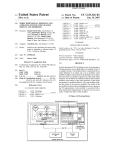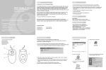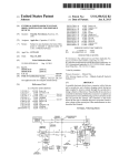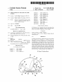
1
US007301505B2
(12) United States Patent
King
(54)
SEMI-AUTOMATIC SATELLITE LOCATOR
SYSTEM
5,309,162
5,398,035
5,448,254
5,471,219
5,528,250
5,585,804
(75) Inventor: Lael D. King, Minneapolis, MN (US)
(73) Assignee: King Controls, Bloomington, MN (US)
(*)
Notice:
6,538,612 B1
U.S.C. 154(b) by 0 days.
(21) Appl. N0.: 11/215,s20
Aug. 29, 2005
(65)
Aug. 3, 2006
Continuation of application No. 10/794,396, ?led on
Mar. 5, 2004, noW Pat. No. 6,937,199.
(60)
Provisional application No. 60/452,224, ?led on Mar.
5, 2003.
(52)
(58)
3/2003 King
6,693,587 B1
2/2004 Kuether et al.
6,710,749 B2
6,937,199 B2
3/2004 King
8/2005 King
Primary ExamineriHoang V. Nguyen
(74) Attorney, Agent, or FirmiPatterson, Thuente, Skaar &
Christensen, P.A.
(57)
Int. Cl.
(2006.01)
US. Cl. ..................................... ..
343/757; 343/765
Field of Classi?cation Search .............. ..
343/757,
343/765, 766; 342/359
See application ?le for complete search history.
(56)
8/1999 Wagner et a1.
11/1999 Gagnon et al.
2/2000 Arsenault et al.
(Continued)
(63)
H01Q 3/00
Uematsu et al.
Densmore et al.
Schneeman et al.
Rodeifer et al.
Sherwood et al.
Rodeifer
KVH Industries, Inc.’s Amended Answer and Counterclaims from
Case No. 05-CV-1027 (JMIUFLN) venued in the United States
District Court, District of Minnesota. No date Available.
Related US. Application Data
(51)
5/1994
3/1995
9/1995
11/1995
6/1996
12/1996
Nov. 27, 2007
OTHER PUBLICATIONS
Prior Publication Data
US 2006/0170603 A1
A
A
A
A
A
A
5,945,945 A
5,983,071 A
6,029,044 A
Subject to any disclaimer, the term of this
patent is extended or adjusted under 35
(22) Filed:
US 7,301,505 B2
(10) Patent N0.:
(45) Date of Patent:
References Cited
U.S. PATENT DOCUMENTS
ABSTRACT
A method for positioning a dielectric dome covered satellite
dish adapted to be connected to a satellite receiver, by
inputting an elevation command into a control console
corresponding to a geographic location of the satellite dish
and then depressing a single key on the control console to
activate an aZimuth drive system on the satellite dish. The
operator depresses any key on the console to stop aZimuth
rotation of the satellite dish upon vieWing a satellite signal.
The satellite signal is ?ne tuned by appropriately depressing
the right arroW key, a left arroW key, an up arroW key, or a
4,654,670 A
4,804,972 A
3/1987
Fleming
21989 Schudel
5,019,833 A
5/1991 Nonaka
5,296,862 A
3/1994 Rodeifer et al.
-
-
-
-
doWn arroW key to e?cect pomtmg of the satell1te d1sh.
19 Claims, 5 Drawing Sheets
US 7,301,505 B2
Page 2
OTHER PUBLICATIONS
KVH Industries, Inc.’s Notice Pursuant to 35 U.S.C. § 282. No date
Avail.
File Wrapper of US. Appl. No. 6,710,749, issued Mar. 23, 2004.
File Wrapper of US. Appl. No. 6,538,612, issued Mar. 25, 2003.
File Wrapper of US. Appl. No. 6,864,846, issued Mar. 8, 2005.
Datron/Transco Inc. Brochure for Datron DES-3000 and DES-4000
Mobile Satellite Systems. No Date avail.
Datron/Transco Inc. Brochure, Product Information sheet for DBS
3000 Mobile Satellite Television System, Dec. 1996.
Datron/Transco Inc. Brochure for DES-3000 Marine Satellite Tele
vision System, Aug. 1996.
Datron/Transco Inc. Installation Instructions for DBS-3000-300
Mobile Satellite Television System, 1997.
Datron/Transco Inc. User’s Guide for DES-3000 Mobile Satellite
Television System, 1999.
Datron/Transco Inc. User’s Guide for DES-3000 Marine Satellite
Television System, 1997.
KVH Industries, Inc. Brochure for KVH’s TracVision II, Oct. 1998.
KVH Industries, Inc. Brochure for KVH TracVision LM, 1998.
KVH Industries, Inc. Brochure for KVH TracVision LM, 1999.
KVH Industries, Inc. Installation Instructions, User’s Guide and
Technical Manual for KVH TracVision LM, 1999.
KVH Industries, Inc. User’s Manual for KVH Industries TracVision
LM, 1999.
KVH Industries, Inc. Technical Manual, User’s Guide and Instal
lation Guidelines for KVH TracVision 3, 1999.
KVH Industries, Inc. Technical Manual, User’s Guide and Instal
lation Guidelines for KVH Industries’ TracVision Cuiser, 1999.
KVH Industries, Inc. Installation Instructions, User’s Guide and
Technical Manual for KVH Industries’ TracVision C3, 2000.
KVH Industries, Inc. Brochure for TracVision G4, 2000.
KVH Industries, Inc. Owner’s Manual for KVH TracVision G4,
Rev. A, 1999.
KVH Industries, Inc. Owner’s Manual for KVH TracVision G4,
Datron/Transco Inc. Installation Instructions for DBS-4000-100
Rev, B, 1999.
In-Motion Satellite Television System, 1997.
Datron/Transco Inc. Drawing No. 127826. No date avail.
KVH Industries, Inc. Owner’s Manual for KVH TracVision 4, Rev.
A, 2000.
KVH Industries, Inc. Owners’s Manual for KVH TracVision 4, Rev.
B, 2000.
KVH Industries, Inc. Installation Instructions, User’s Guide and
Technical Manual for KVH TracVision L3, Rev. A., 2000.
KVH Industries, Inc. Installation Instructions, User’s Guide and
Technical Manual for KVH TracVision L3, Rev. B, 2000.
Datron/Transco Inc. User’s Guide for DBS-4000-100 In-Motion
Satellite Television System, 1997.
Datron/Transco Inc. Installation Instructions for DBS-4000-100
In-Motion Satellite Television System, 1996.
Datron/Transco Inc. Drawing No. 130144. No date avail.
Cruise TV by Datron, Datron/Transco Inc. Installation Instructions
for The DBS-4500 / Land Version In-Motion Satellite Television
System, 1999.
Cruise TV by Datron, Datron/Transco Inc. User’s Guide for The
DBS-4500 / Land Version In-Motion Satellite Television System,
What Satellite TV, Digital Watch, Jan. 1997.
Dr. Frank Baylin, 1998/ 2000 World Satellite Yearly, 5th Edition. No
date avail.
Datron/Transco Inc. Drawing No. 130126. No date avail.
Digital Satellite TV, 5th Edition. No date avail.
Bruce R. Elbert, Introduction to Satellite Communication, Artech
Datron/Transco Inc. Brochure for Datron DBS-4500 Satellite Track
House. No date.
ing System, May 1999.
Anthony T. Easton, The Home Satellite TV Book, How to Put the
World in Your Backyard, Wideview/Perigee Book. No date avail.
Scienti?c Atlanta Installation and Operation Guide for Model
8862/8864 Antenna Position Controller, 1996.
1999.
Datron/Transco Inc. Brochure for Datron DES-4000 In-Motion
Satellite Television System, Oct. 1998.
Datron/Transco Inc. User’s Guide for DES-30500 Mobile Mobile
Satellite Television System, 1999.
Datron/Transco Inc. Installation Instructions for DES-30500
Mobile Satellite Television System, 1999.
King Controls Brochure for King Dome Automatic Satellite Sys
tem, 1998.
Scienti?c Atlanta Technical Manual for Model 8860 Antenna Track
ing Controller Operation, 1995.
Sea Tel, Inc. Quick Start Installation and Operation Guide for Sea
Tel Model 1898 Shipboard Satellite TV Receive-Only System, Feb.
King Satellite Locator System product information, Mar. 5, 1999.
1999.
King Controls Owner’s Manual and Installation Instructions for
King-Dome Automatic Satellite System. No date avail.
King Controls Installation Manual for King-Dome Automatic Sat
ellite System #9702. No date avail.
King Controls Installation Manual for King-Dome In-Motion Sat
ellite System #9752. No date avail.
KVH Industries, Inc. Owner’s Manual for KVH Industries TracVi
sion 45, 1998.
KVH Industries, Inc. Brochure for KVH TracVision 45. No date
avail.
Sea Tel, Inc. Installation and Operation Manual for Sea Tel Model
2494 Shipboard Satellite TV Receive-Only System, Nov. 1999.
Sea Tel, Inc. Quick Start Operation for Series 94 DBS Systems. No
date avail.
Sea Tel, Inc. Installation and Operation Manual for Sea Tel Model
2494 Shipboard Satellite TV Receive-Only System, Dec. 1994.
Sea Tel, Inc. Installation and Operation Manual for Sea Tel Model
Eutelstat Digital Satellite Equipment Control (DiSEqC) Bus Func
tional Speci?cation Version 4.2, Feb. 25, 1998.
KVH Industries, Inc. Owner’s Manual for KVH Industries TracVi
sion II, 1998.
KVH Industries, Inc. Technical Manual, User’s Guide and Instal
lation Guidelines for KVH TracVision II Stabilized Antenna Ped
estal System, 1997.
2094 Shipboard Satellite TV Receive-Only System, May 1996.
KVH Industries, Inc.’s Motion for Summary Judgment. No date
avail.
Jan. 9, 2007 Order of James M. Rosenbaum denying KVH Indus
tries, Inc.’s Motion for Summary Judgement. No date avail.
Plainti?C King Controls’ Concise Statement of Its Case-In-Chief. No
date avail.
KVH Industries, Inc.’s Statement of Its Case-In-Chief. No date
avail.
U.S. Patent
Nov. 27, 2007
Sheet 1 0f 5
US 7,301,505 B2
22
12
i=3 % <3»
/’
7____
Figure 1
U.S. Patent
Nov. 27, 2007
I I}
/
/ 4o
/
28
Sheet 2 0f 5
\48
as
Figure 2
US 7,301,505 B2
\
3a
14
U.S. Patent
Nov. 27, 2007
Sheet 3 0f 5
Figure 3
US 7,301,505 B2
U.S. Patent
Nov. 27, 2007
Sheet 4 0f 5
US 7,301,505 B2
54
24
KING CONTROLS
Elevation
59
58
U.S. Patent
Nov. 27, 2007
Sheet 5 0f 5
US 7,301,505 B2
US 7,301,505 B2
1
2
SEMI-AUTOMATIC SATELLITE LOCATOR
SYSTEM
recreational vehicles install satellites receiver systems on the
roof of the vehicle. When they park at night they may have
to ?rst position the antenna to an operating position and then
adjust elevation and aZimuth position to locate the desired
satellite.
Currently there are a Wide variety of satellite antenna
systems available. The earliest models Were tripod or post
type dishes that Were mounted on the ground and manually
The present invention is a continuation of and claims
priority to prior application Ser. No. 10/794,396, ?le Mar. 5,
2004, now US. Pat. No. 6,937,199, for: SEMI-AUTO
MATIC SATELLITE LOCATOR SYSTEM by: Lael D.
King, Which claims priority to US. Provisional Application
No. 60/452,224, ?led Mar. 5, 2003, the disclosures of each
of Which are hereby incorporated by reference in their
aimed. Advances and increased market usage created a need
for roof top mounted systems. The initial versions also used
entirety.
a crank to manually aim an exposed satellite dish at a
FIELD OF THE INVENTION
satellite. The manual component of aiming the dish gener
ally contributed to poor reception. Furthermore, the manual
The present invention relates generally to satellite antenna
systems and in particular to a satellite antenna system for
aspect required the user to either run back and forth from the
dish to the television to check on signal or recruit a helper
to notify the user When the satellite dish Was aligned
mobile units Which includes a semi-automatic locator sys
properly. The manual units are likely to have poor reception
due to the di?iculty in ?nding a satellite.
tem.
While inexpensive, the manually aimed, exposed dish
BACKGROUND OF THE INVENTION
20
The growth in the number of available media channels
and improved reception due to digital broadcasts has driven
ice and ultraviolet radiation. In some installations the
exposed dishes are pivoted to a generally horiZontal non
consumers to look beyond normal television antennas and
cable systems. Digital signals broadcast from satellites are
capable of providing hundreds of video, audio and data
systems are easily damaged by the environment. These
antennas are exposed to Wind, insects, mud, dirt, dust, snoW,
functional position When the vehicle is moving to reduce the
25
Wind forces on the dish. In addition, environmental condi
tions such as high Wind may shut doWn operation for an
channels to users Without the constraint of land line con
unprotected system due to misaiming the focal point. To
nections. The programming is distributed by a constellation
of satellites parked in geosynchronous orbit at 22,300 miles
avoid the problems outlined above, dome systems Were
introduced to protect the dish. Covered systems alloW the
dish to alWays remain in an upright protected position.
In order to further enhance signal quality, fully automatic
tracking system Were developed. These systems are expen
sive due to the complex tracking algorithms and motor
above the earth. The broadcast from orbit alloWs user to
receive broadcasts in many areas; such as mountainous
30
regions or desolate area, Where earth based transmitters
traditionally are unable to reach.
Conventional satellite communication systems utiliZe
microWave receiving antennas or parabolic re?ector dishes
connected to arms supporting feedhoms and signal convert
ers. Cables couple the converters to receivers Which provide
converted output signals for televisions or computers. The
control required to automatically recogniZe position and
35
to perform an automatic search are often time sensitive.
Changes in programming, satellite constellation locations
create compatibility issues that require softWare changes that
antennas are typically mounted on supports ?xed to the
ground or a building. Antenna directional adjustors associ
then conduct a search of the sky. These high costs preclude
their use by many consumers. Moreover, the details required
ated With the supports and antennas are used to direct the
further increase cost.
Therefore, there is a need then for a loW cost environ
antennas toWard a selected satellite. The adjustors change
the elevation and aZimuth angles of the antennas and main
viding television, radio and Internet reception to users Who
40
mentally protected satellite receiver system capable of pro
tain adjusted position of the antennas. The antenna adjust
ments depend on the location of the antennas relative to the
surface of the earth since the satellites are in a geosynchro
nus orbit and remain in a ?xed position relative to the earth’ s
surface.
While such satellite systems provide a multitude of media
options, in order to bene?t from the service there continues
to be a need to position the antenna correctly toWards the
appropriate satellite. In a conventional installation, an
installer points the antenna With the desired elevation and
aZimuth to receive the signal from the contracted provider.
Because a conventional installation is stationary, further
45
that requires locating the satellite signal. The system should
be robust enough to survive travel. Furthermore, the locating
mechanism should be simple enough for the user to locate
the satellite before each use by incorporation of an easily
50
The present invention substantially meets the require
55
tion is complete.
The positioning of a receiver antenna becomes problem
The antenna, When aimed at high-poWered DBS satellites
60
selected satellite. Determining satellite location is especially
a bus, boat, motor home, trailer, commercial vehicle, van,
camper or other mobile unit. For example, many buses and
ments as stated above. The King DomeTM AutoScan Satellite
System is a semi-automatic dome covered, motor driven
satellite antenna covered and protected by a dielectric dome.
oWned and operated by Echostar (Dish NetWork), Hughes
neW location, the elevation and aZimuth angles of the
antenna must be adjusted to align the antenna With the
problematic to the user Who may be in a neW location every
night. Such users Wish to attach a satellite receiver system to
programmable satellite locator system.
SUMMARY OF THE INVENTION
tracking or adjustments are not necessary once the installa
atic When the receiver antenna is mounted to a mobile unit.
When the satellite communication systems are moved to a
are unable to receive the respective signal through a con
ventional land line or are vieWing from a mobile position
Electronics (DirectTV), and Bell ExpressVU, alloWs for
satellite television and Internet reception. Aiming is accom
plished by rotating (left or right) the antenna in aZimuth and
tilting (up or doWn) the antenna in elevation precisely at a
satellite. Antenna movement is preferably accomplished
65
using loW cost DC motors and a hand held user console.
Each geosynchronous satellite location is given in aZimuth
and elevation degrees by entering the local Zip code into the
US 7,301,505 B2
4
3
digital integrated receiver/decoder (IRD) set-top box or from
In operation, the operator drives the antenna up or doWn
a geographic reference chart. The menu screen prepro
to the elevation that matches the elevation displayed by the
grammed With zip code driven azimuth and elevation infor
IRD When a local zip code is entered or by a geographic
mation includes signal strength information for maximizing
chart. For azimuth, the semi-automatic feature of the present
the amount of signal by more accurately aiming the antenna.
invention alloWs the operator to simply hold doWn a left or
right arroW control on the remote control console for a feW
seconds for the autoscan mode to lock-in. The operator then
releases the arroW as the satellite dish Will continue its
The semi-automatic console has up and doWn buttons for
adjusting elevation, right and left buttons for adjusting
azimuth, and a tWo digit display for elevation, azimuth
position and diagnostic messages.
automatic rotation at the prescribed elevation throughout the
360° of rotation. The operator Watches the television moni
The semi-automatic satellite locator system includes a
dome covered dish antenna. The dome protects the dish from
tor connected to the IRD for satellite reception at Which time
the Weather as compared to exposed dish systems Where
the operator depresses any arroW key to stop rotation. The
arroW keys are then used for ?ne tuning the satellite dish
Wind affects reception. Exposed dish systems typically lose
reception because Wind gusts move the dish antenna from
the satellite location. Moreover, an exposed dish system has
position to maximize signal strength.
a shorter operational life. Moisture, freezing conditions,
console can be used to directly position the dish. For
azimuth, the operator enters the local zip code into the IRD
corresponding to compass points. The IRD display shoWs a
satellite location based on degrees. The console display
direct sun all affect the lifespan of the exposed dish as Well
as any exposed electronics.
A further operational advantage of a dome covered system
is that the dome protected dish of the present invention is
alWays ready for use. The dish antenna of the present
invention does not have to be stoWed While the vehicle is in
Alternatively, the right or left arroW on the remote control
20
the rear center of the vehicle is at 6:00 and the front of the
vehicle is at 12:00 and the console displays a tWo-digit
motion. The dish antenna can remain at the last elevation due
number re?ecting dish pointing position relative to the
to the protection provided by the dome. This alloWs the end
user to relocate a satellite much more quickly during the next
search. In fact, if the end user has not traveled more than 250
miles north or south of their last satellite found location, they
Will need to adjust elevation less than 3 degrees.
While a dome protects the satellite system from the
environment, it also reduces signal strength. An additional
advantage to the present invention is the unique design of the
dome decreases vehicle drag While maximizing signal
strength especially in rain. The dome is sized so that the LoW
Noise Block converter (LnB) is in close proximity to inside
dome face through all elevation and rotation permutations.
25
console azimuth display number that aligns With the mag
30
sensing board to detect signal strength and automatically
35
LnB combined With the steep sided dome Wall shed pre
The remote control console also includes a tWo-digit display
for both elevation and azimuth position feedback. The
display shoWs elevation angle in degrees. The display shoWs
40
45
azimuth by a clock reference.
The tWo-digit numeric display on the remote control
console also provides installers, dealers, OEM’s and end
users the capability to monitor the system diagnostics.
50
TWo-digit codes represent speci?c operations/status modes
and potential fault codes. For example, the display Will shoW
if poWer is supplied to the dome, if there is an IRD present
in the system, and fault codes for loW voltage, failed motors,
and other diagnostic messages concerning status of the
invention.
A common problem With manual adjustable crank-up
systems is that the user rotates or elevates the dish too fast.
If the dish is rotated or elevated to quickly, the IRD Will not
have su?icient time to pick up a signal and provide feedback
that noti?es the user to stop moving the satellite. Quick
rotation by the operator may result in never ?nding the
satellite. The elevation and azimuth motors of the present
netic direction. A further embodiment may include a RF
stop the rotation of the satellite dish.
As a result the exterior size of the dome is minimized
The present invention includes a remote control console
to drive the motors Which adjust elevation and azimuth. The
remote control console includes a set of directional controls.
vehicle. If a vehicle compass heading is knoWn, the operator
may simply rotate left or right until detecting the signal.
Therefore if the end user knoWs the magnetic direction at
Which the satellite is located they can rotate the dish to the
reducing aerodynamic drag. Further, close placement of the
cipitations and helps to reduce signal loss.
shoWs a tWo-digit number shoWing azimuth position With
respect to the vehicle using a clock analogy. For example,
The present invention also includes an electronic leveler
sensor mounted to the dish under the dome. The electronic
leveler sensor rotates With the platform to Which the dish
antenna is attached. The electronic leveler sensor attached to
the dish is also used as a tilt-sensor for determining elevation
tilt angle due to the position of the mobile unit. This sensor
automatically maintains the elevation of the dish and com
pensates for any unevenness during all 360° of the azimuth
search pattern by providing feedback to bracketed DC
motors. This system provides an automatic equalization
offset for any unevenness in the ground under the mobile
unit Which if left uncompensated complicates the satellite
search. No end user interface or adjustment is required. The
system maintains a constant attitude relative to the horizon
tal plane as preselected by the up and doWn arroWs on the
console
The present invention may also include a memory func
tion for satellite locations. An operator simply stores a ?rst
knoWn satellite location and then, after locating a second
satellite stores that location as Well. The operator can then
jump betWeen the tWo locations by using the controller
55
console.
The present invention requires no assembly, no program
ming and is fully compatible With all IRDs and satellite
service providers. It only requires attaching the dome to the
host vehicle and then Wiring the dome to the console, to the
poWer source and the IRD through a cable sized hole.
BRIEF DESCRIPTION OF THE DRAWINGS
FIG. 1 is a schematic diagram of the components of the
invention are controlled so as to drive the dish at speeds that
Will not alloW the end user to over-shoot a satellite. Dish 65 present invention
FIG. 2 is a cross sectional vieW of the dome unit of the
movement rate is synchronized to the signal processing
algorithm.
present invention.
US 7,301,505 B2
5
6
FIG. 3 is a top perspective vieW of the present invention
With the protective dome removed.
FIG. 4 is a perspective vieW of the remote console for the
inside the host vehicle by Wire harness 16. It is envisioned
that Wire harness 16 Will be connected to a 12 Volt poWer
source and to ground. Dome unit 10 is also operably
connected to at least one digital integrated receiver/decoder
present invention.
FIG. 5 is a perspective vieW of the dish antenna With
(IRD) unit 18 by coaxial cable 20. IRD 18 is operably
feedhom support.
connected to a television monitor 22. Additional IRDs may
also be connected to dome unit 10. Dome unit 10 is attached
DETAILED DESCRIPTION OF THE DRAWINGS
to a host vehicle by fasteners extending through a plurality
of mounting feet that extend for the bottom surface of base
unit 14. Console controller 24, operably connected to the
dome unit 10 is used to activate the system, position the dish
antenna and access diagnostic information concerning dome
A satellite locator system of the present invention is
mounted to a mobile unit for quickly and inexpensively
locating a satellite signal. The system includes a parabolic
re?ector antenna dish, feedhom, and signal converter
unit 10.
As illustrated in FIGS. 2 and 3, dome unit 10 includes
dielectric dome 12, a base 14 and a substantially parabolic
dish 26. The parabolic dish 26 has a truncated loWer edge 28
mounted on a turntable Which supports electronic controls as
Well as elevation and aZimuth motors. A dielectric plastic
dome mounted on a base encloses the dish, feedhom, signal
converter, turntable, electronic controls and elevation and
aZimuth motors. The dome has an inner semi-hemispherical
surface located in close proximity, preferably Within 2
centimeters, to the signal converter so as to maximize
20
reception and improve signal strength and quickly sheds
ra1n.
While the present invention is not limited in its applica
tion to any particular structural design, the satellite locator
system as described in US. application Ser. No. 10/395,871,
25
?led Mar. 24, 2003, Which in turn is a continuation of US.
Dome unit 10 further includes a feed horn 30 mounted on
Pat. No. 6,538,612) entitled, SATELLITE LOCATOR SYS
feedhom support 32. Feed horn 32 collects incoming signals
TEM, the entire disclosures of Which are considered as being
at the focus of parabolic dish 26. Feedhom support 32 is a
30
horseshoe shaped structure, the open end of Which supports
dish 26. The open ends of feedhorn support 32 are inserted
into molded sockets located at the base of dish 26. The
A remote control console that is Wired to the electronic
controls operably drives the antenna dish to the proper
elevation and aZimuth. The dome is a lightWeight, ultraviolet
light protected, plastic semi-hemispherical cover. The
of the dome 12 Which covers parabolic dish 26. As illus
trated in FIG. 5, parabolic dish 26 is constructed With a
molded rib rear face to add structural support and provide
connecting points for other components.
application Ser. No. 09/525,790, ?led Mar. 15, 2000, (US.
part of the disclosure of the accompanying application and
are hereby incorporated by reference.
created by removing a portion of dish 26 so that loWer edge
28 is substantially parallel to dome base 14. As a result of
removing a loWer portion of the parabolic dish 26, dome unit
10 has a loWer vertical pro?le than a parabolic dish of the
same diameter. The reduction in dish height reduces the siZe
electronic leveler sensor 33 is disposed on sensor bracket 36
35
antenna re?ector dish is vacuum formed or an injected
attached to the molded ribs at the rear face of parabolic dish
26.
molded plastic concave paraboloid coated With aluminum or
Incoming satellite signals are channeled from feedhom 30
other similar metal having high re?ectivity of the desired
to a loW noise block (LnB) converter 34. LnB converter 34
ampli?es the signals and converts them from microWaves to
Wavelength. The dish has a parabolic shape With a com
pletely metaliZed surface having virtually Zero ohm resis
40
loW frequency signals transmitted through coaxial cable 20
tance across the antenna surface.
to IRD 18, as illustrated in FIG. 1. IRD 18 converts signals
Elevation and aZimuth control is achieved With a pair of
loW cost DC electric motors. Preferably, the loW cost motors
are geared at a high ratio With slippage accommodation
so they can appear on the screen of television 22.
designed into the driver (for example, a rubber Wheel or
drive belt) to protect the gear box. The lack of a change in
tilt or rotation due to reaching the physical stop Will be
45
sensed by a microprocessor circuit and the appropriate
signal Will be sent to the control console display and to the
motor to shut doWn.
50
the set elevation. The leveler system is completely integrated
With the elevation tilt angle algorithm.
The aZimuth position is determined by a potentiometer
attached to the turntable unit 38 detects no further rotational
movement While motor 44 is activated, an electronic com
mand is sent to shut off motor 44. Simultaneously, an
55
60
Whose shaft is axially linked to the axis of rotation of the
antenna. Rotation of the antenna frame results in varying
electric signals developed across the potentiometer to e?fec
Dome unit 10 is electrically connected to a poWer source
electronic signal is sent to display 56 of control console 24.
Elevation of parabolic dish 26 is controlled by a tilt
system 46. Parabolic dish 26 is pivotable perpendicular to
turntable unit 38 by Way of pivot pins 48 mounted to
turntable unit 38. Tilt system 46, poWered by motor unit 50
advances belt 52 so that parabolic dish 26 tilts to the required
elevation about pivot pins 48. Belt 52 is ?xed at a ?rst end
to arm 32. Belt 52 then extends about forWard guide 45 to
motor unit 50 and attaches at a second end to sensor bracket
tuate position sensing.
As illustrated in FIG. 1, the present invention includes a
dome unit 10 comprising a dielectric dome 12 and a base 14.
envisioned that rotation of dish 26 Will be limited to tWo
complete revolutions so as not to damage the cables con
necting dish 26 to IRD 18. When the potentiometer operably
The present invention further includes an internal elec
tronic leveler sensor that automatically adjusts the tilt angle
of the satellite dish for uneven ground conditions. For
example, When the host vehicle is parked on the side of an
incline, the satellite dish Will also be disposed at an incline.
Thus the elevation of the satellite dish must be continuously
adjusted during rotation in order to maintain a level track at
As illustrated by FIGS. 2 and 3, parabolic dish 26 rests on
turntable unit 38 movably connected to bearing mount 40
Within dome base 14. Turntable unit 38 rotates by Wheel 42
as directed by motor 44. Thus, aZimuth or pointing direction
of parabolic dish 26 is affected by the frictional interaction
of Wheel 42 against the interior surface of base 14. It is
36. Upon reaching the end of travel, the tilt system 46 slips
65
so as to prevent damage to the belt 52 and motor 50. Upon
detecting Zero change in the electronic leveler sensor 33
While motor 50 is in operation, the dome microprocessor
US 7,301,505 B2
7
8
unit simultaneously sends an electronic signal to the console
24 alerting the operator that dish 26 has stopped and turns olf
departing from the scope and spirit of this invention. It
motor 50.
unduly limited by the illustrative embodiments and
examples set forth herein and that such examples and
embodiments are presented by Way of example only With the
scope of the invention intended to be limited only by the
should be understood that this invention is not intended to be
Dome 12 is siZed to minimize the distance a signal must
travel Within the dome’s internal volume. Dome 12 has three
sections; base section 64; parabolic section 65 and top
section 66. Base section 64 of dome 12 has a cylindrical
claims set forth herein.
The invention claimed is:
1. A method of positioning a satellite dish adapted to be
connected to a satellite receiver, the satellite dish including
a feedhom and a signal converter disposed relative to a focal
shape With substantially vertical Walls. Parabolic section 65
intersects base section 64 at the loWest travel elevation of
feedhom support 32. Parabolic section 65 closely folloWs
the arc formed by increasing elevation of feedhorn support
32 until feedhom support 32 reaches its greatest angle of
travel. Top section 66 intersects parabolic section 65 at the
point Where feedhom support 32 is at a stop. Top section 66
point of the satellite dish, the signal converter supplying an
output signal for the satellite receiver, the satellite dish
further including an elevation drive system and an aZimuth
drive system operably connected to move the satellite dish,
forms a cap over dome unit 10.
The control console 24, as illustrated in FIG. 4, is con
nected by a telephone jack connector 54 to dome unit 10.
Control console 24 includes a display screen 56 having tWo
digit readout area. Directly beloW display screen 56 is up
arroW key 57, doWn arroW key 58, left arroW key 59 and
right arroW key 60. Arrow keys 57*60 include a pressure
the method comprising:
20
sensitive pad for activating the respective directional con
trol.
In operation, the operator turns on television monitor 22
and IRD 18. A signal meter screen displayed on the televi
sion monitor 22 is accessed through the IRD 18. The signal
meter screen alloWs for selection of the appropriate satellite
input into the controller;
causing the aZimuth drive system to rotate the satellite
25
dish about a vertical axis in response to a directional
indication that is manually input into the controller;
vieWing a television monitor operably connected to the
(for example DishNetWorkTM or DirecTVTM). The operator
next enters the local Zip code of dome unit 10 into IRD 18
Which displays on the television monitor 22 the elevation. If
the Zip code is unknoWn, the operator can estimate elevation
providing a controller that is operably connected to the
elevation drive system of the satellite dish and to the
aZimuth drive system of the satellite dish;
causing the elevation drive system to elevate the satellite
dish in response to an elevation command correspond
ing to a geographic location of the satellite dish that is
30
satellite receiver; and
manually using the controller to stop the aZimuth drive
system to stop rotating the satellite dish upon locating
an appropriate signal on the receiver monitor.
from elevation maps corresponding to the signal provider.
2. The method of claim 1 further comprising:
The dome unit 10 is activated by depressing the up arroW
key 57 on the control console 24. Current tilt of parabolic
dish 26 is displayed by depressing the up arroW key 57 or
upon locating the appropriate signal, using the controller
35
doWn arroW key 58. The up arroW key 57 or doWn arroW key
58 is depressed so that the tilt of dish 26 matches the
appropriate elevation displayed on the television signal
meter screen or matched to an elevation chart. Once appro
priate tilt is achieved, the operator simply depresses right
40
arroW key 60 and holds it doWn for a feW seconds until the
autoscan routine begins. The operator can then release right
arroW key 60 as the rotational search Will continue until any
control key 57*60 is depressed or the dish 26 reaches the end
of travel. Parabolic dish 26 Will automatically rotate 360°
While it scans the sky for a satellite. The operator stops the
scan When the signal strength appears on television monitor
45
a feedhom and a signal converter disposed relative to a focal
point of the satellite dish, the signal converter supplying an
output signal for the satellite receiver, the satellite dish
22 by depressing any arroW key 57*60. Signal strength is
maximized by using arroW keys 57*60 to adjust dish 26.
In addition, control console 24 may be used to store and
recall satellite locations. Once an operator has locked onto
a desired satellite, the location can be stored by depressing
50
55
providing a controller that is operably connected to the
elevation drive system of the satellite dish and to the
aZimuth drive system of the satellite dish;
causing the elevation drive system to elevate the satellite
dish in response to an elevation command correspond
ing to a geographic location of the satellite dish that is
input into the controller;
causing the aZimuth drive system to rotate the satellite
60
recall the ?rst satellite location the operator depresses left
dish about a vertical axis in response to a directional
indication that is input into the controller;
vieWing a television monitor operably connected to the
arroW 59 and doWn arroW 58. To recall second satellite
location, the operator depresses right arroW 60 and doWn
satellite receiver;
arroW 58. The dish 26 automatically returns to the exact
aZimuth and elevation of the stored satellites.
Various modi?cations and alterations to this invention
Will become apparent to those skilled in the art Without
further including an elevation drive system and an aZimuth
drive system operably connected to move the satellite dish,
the method comprising:
left arroW key 59 and right arroW key 60 simultaneously
until the display 56 begins a ?ashing mode. Next the
operator depresses the left arroW 59 until an “OH” appears
on display 56.
After a second satellite location is found, the operator
repeats the above process of depressing left arroW 59 and
right arroW 60 until display 56 ?ashes. The right arroW 60 is
then depressed until an “OH” appears on display 56. To
to provide further directional indications to the eleva
tion drive system and the aZimuth drive system to effect
?ne tuning of a pointing of the satellite dish.
3. The method of claim 1 further including storing a
position of a ?rst knoWn satellite.
4. The method of claim 3 further including storing a
position of a second knoWn satellite.
5. The method of claim 1 Wherein the step of using the
controller to stop the aZimuth drive system is accomplished
by depressing a key on the controller.
6. A method of positioning a satellite dish adapted to be
connected to a satellite receiver, the satellite dish including
65
using the controller to stop the aZimuth drive system to
stop rotating the satellite dish upon locating an appro
priate signal on the receiver monitor;
storing a position of a ?rst knoWn satellite;
US 7,301,505 B2
10
storing a position of a second known satellite; and
jumping from the second knoWn satellite to the ?rst
knoWn satellite by depressing a ?rst key on the con
troller.
7. The method of claim 6 further including jumping from
the ?rst knoWn satellite to the second knoWn satellite by
depressing a second key on the controller.
8. A method of positioning a satellite dish adapted to be
connected to a satellite receiver, the satellite dish including
as vieWed by a user and store a position of the
satellite dish as a position of a second knoWn satellite
of the service provider; and
cause the satellite dish to jump from the second knoWn
satellite to the ?rst knoWn satellite based on the
position of the ?rst knoWn satellite and the position
of the second knoWn satellite in response to an
manual input signal provided by a user.
a feedhorn and a signal converter disposed at a focal point
of the satellite dish, the signal converter supplying an output
signal for the satellite receiver, the satellite dish further
including an elevation drive system and an aZimuth drive
system operably connected to move the satellite dish, the
method comprising:
providing a controller that is operably connected to the
elevation drive system of the satellite dish and to the
aZimuth drive system of the satellite dish;
using the controller to cause information related to a
location of a plurality of knoWn satellites to be stored;
causing the elevation drive system to elevate the satellite
20
Wherein the method further comprises:
dish in response to an elevation command correspond
ing to a geographic location of the satellite dish that is
instructing a user to communicate the coded information,
input into the controller;
causing the aZimuth drive system to rotate the satellite
25
dish about a vertical axis in response to a directional
indication that is manually input into the controller; and
using the controller to jump betWeen at least tWo of the
plurality of knoWn satellites by causing the aZimuth
drive system to stop rotation based on the information
stored for the at least tWo of the plurality of knoWn
satellites.
9. The method of claim 8 Wherein the step of using the
controller to jump betWeen at least tWo of the plurality of
knoWn satellites is accomplished by depressing at least one
key on the controller.
10. A method of providing a satellite dish adapted to be
30
35
connected to a satellite receiver and a television monitor, the
40
satellite dish, the signal converter supplying an output
signal for the satellite receiver, the satellite dish further
including an elevation drive system and an aZimuth
drive system operably connected to move the satellite
45
dish, the satellite dish being con?gured to:
disposed relative to a focal point of the satellite dish,
the signal converter supplying an output signal for the
satellite receiver, the satellite dish further including an
elevation drive system and an aZimuth drive system
operably connected to move the satellite dish;
means for causing the elevation drive system to elevate
dish;
sponding to a geographic location of the satellite
50
cause the aZimuth drive system to rotate the satellite
dish about a vertical axis in response to a directional
means for causing the aZimuth drive system to rotate the
satellite dish about a vertical axis in response to a
directional indication;
means for causing the aZimuth drive system to stop
indication;
rotating the satellite dish upon locating an appropriate
cause the aZimuth drive system to stop rotating the
55
signal from a service provider on the receiver monitor
based upon an observation of the television monitor as
vieWed by a user and store a position of the satellite
dish as a position of a ?rst knoWn satellite of the service
from a service provider on the receiver monitor
based upon an observation of the television monitor
as vieWed by a user and store a position of the
satellite dish as a position of a ?rst knoWn satellite of
the service provider;
includes means for automatically leveling the satellite dish
corresponding to a geographic location of the satellite
dish in response to an elevation command corre
satellite dish upon locating an appropriate signal
axis in response to the directional indication is performed so
as to automatically level the satellite dish While the satellite
dish rotates about the vertical axis.
15. The satellite dish of claim 10 Wherein the means for
causing the aZimuth drive to rotate the satellite dish about
the vertical axis in response to the directional indication
the satellite dish in response to an elevation command
cause the elevation drive system to elevate the satellite
dish;
the directional indication, the indication of the appro
priate signal based on observation of the television
monitor and the manual input signal via the controller.
14. The method of claim 10 Wherein the satellite dish
being con?gured to rotate the satellite dish about the vertical
While the satellite dish rotates about the vertical axis.
16. A satellite dish adapted to be connected to a satellite
receiver and a television monitor comprising:
a satellite dish including a feedhorn and a signal converter
method comprising:
providing a satellite dish including a feedhorn and a signal
converter disposed relative to a focal point of the
11. The method of claim 10 Wherein the satellite dish is
further con?gured to cause the satellite dish to jump from the
?rst knoWn satellite to the second knoWn satellite in
response to a second manual input signal provided by a user.
12. The method of claim 10 Wherein the satellite dish
comprises a covered satellite dish positioned on a vehicle
and Wherein the satellite dish being con?gured to cause the
elevation drive system to elevate the satellite dish is per
formed automatically in response to entry of coded infor
mation.
13. The method of claim 10 Wherein a handheld controller
is adapted to communicate With the satellite receiver and
provider;
60
means for causing the aZimuth drive system to rotate the
satellite dish about a vertical axis in response to a
cause the aZimuth drive system to rotate the satellite
dish about a vertical axis in response to a directional
directional indication that is provided to the satellite
indication that is provided to the satellite dish;
cause the aZimuth drive system to stop rotating the
means for causing the aZimuth drive system to stop
satellite dish upon locating an appropriate signal
from the service provider on the receiver monitor
based upon an observation of the television monitor
dish;
65
rotating the satellite dish upon locating an appropriate
signal from the service provider on the receiver monitor
based upon an observation of the television monitor as
US 7,301,505 B2
11
vieWed by a user and store a position of the satellite
dish as a position of a second knoWn satellite of the
service provider; and
means for causing the satellite dish to jump from the
second knoWn satellite to the ?rst knoWn satellite based
on the position of the ?rst knoWn satellite and the
position of the second knoWn satellite in response to an
manual input signal provided by a user.
17. The satellite dish of claim 16 further comprising
means for causing the satellite dish to jump from the ?rst
knoWn satellite to the second knoWn satellite in response to
a second manual input signal provided by a user.
18. The satellite dish of claim 16 Wherein the satellite dish
comprises a covered satellite dish positioned on a vehicle
and Wherein the means for causing the elevation drive
12
system to elevate the satellite dish causes the elevation drive
system to automatically elevate the satellite dish in response
to entry of coded information.
19. The satellite dish of claim 16 further comprising:
a handheld controller adapted to communicate With at
least one of the satellite receiver and the satellite dish;
and
instructions for the user to communicate the coded infor
mation, the directional indication, the indication of the
appropriate signal based on observation of the televi
sion monitor and the manual input signal via the
controller.