1
Chapter 3
Getting Started
3- Generating Tire Models
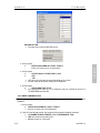
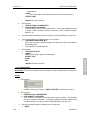
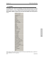
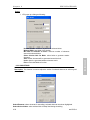
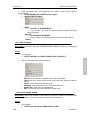
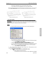
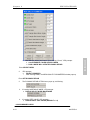
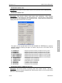
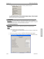
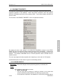
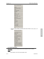
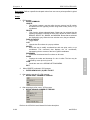
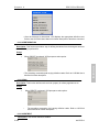
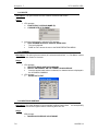
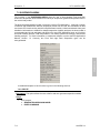
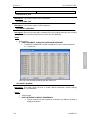
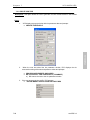
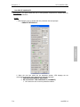
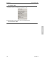
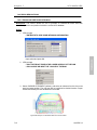
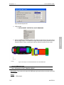
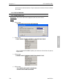
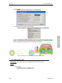
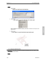
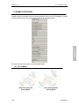
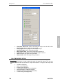
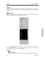
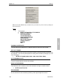
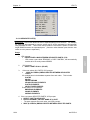
After entering the TIRE MENU, the user selects GENERATE and is offered the TIRE
PARAMETER dialogue box. Default values for tire geometry, mass and inflation pressure
are edited to the user's parameters.
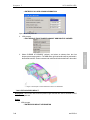
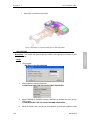
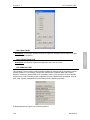
Once the tire geometry is defined, VPG prompts the user for the location of the tire. The
user may define the location of the tire through an X, Y, Z position, or by selecting an existing
node /point, or by selecting a location on an existing suspension system.
Tire modeling is discussed in Section 7.3. This topic is also described in the VPG/Structure
Tutorial.
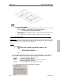
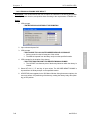
4- Auto-Generating a Road Surface
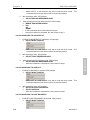
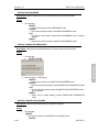
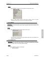
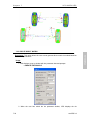
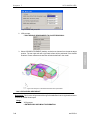
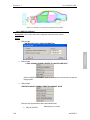
Next, contact between the road surface and the tires are determined using the
FIVE_NODES_TO_SURFACE interface type. The road is then constrained in the Y, Z, and
rotational directions using the material property assigned to the road. Next, a velocity is
assigned to the road using the BOUNDARY_PRESCRIBED_MOTION card.
Details on ROAD SURFACE libraries may be found in Chapter 7, Section 1.
5- Adding a Body Model
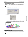
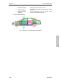
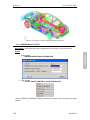
The body to chassis/suspension attachment process depends upon what type of body model
the user wishes to use for analysis (deformable or rigid).
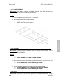
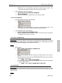
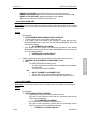
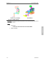
Rigid Body - The rigid body model is constrained to the rigid beams that define the body
attachment points on the suspension.
Deformable Body - The specific coordinates for the body attachment points must be entered
when the user defines the Extra Node Coordinates for the front/rear suspension models.
This ensures that the generated suspension would fit the specific body model. The user then
creates weld spiders between the mounts on the vehicle and the rigid body beams on the
suspension. Next the user defines the BODY_LOAD_DEFINITION_CARD to define the
gravity.
After defining the gravity, the user pre-loads the suspension using the ELEMENT
DEFINITION CARD.
6- Defining VPG Analysis Control Parameters
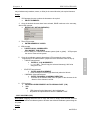
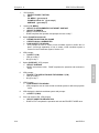
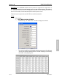
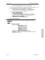
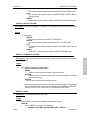
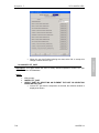
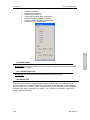
First, the CONTROL ENERGY and CONTROL TERMINATION cards must be defined.
Next, the output control interval data for the ASCII database must be determined. Then the
BINARY DATABASE cards must be edited to control the output interval of the results and
restarts.
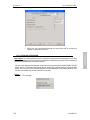
7- Analysis Submission
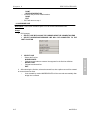
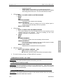
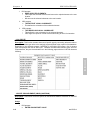
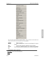
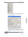
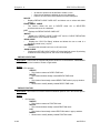
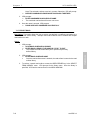
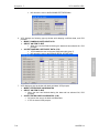
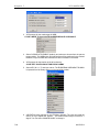
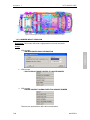
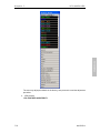
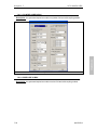
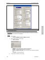
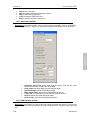
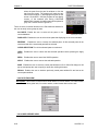
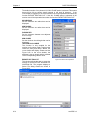
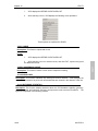
From the ANALYSIS menu, select DYNA INPUT FILE OPTIONS, edit the dialogue box, and
3-3
eta/VPG3.4
GETTING STARTED
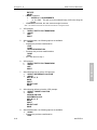
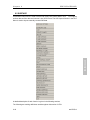
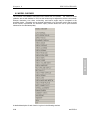
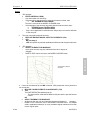
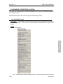
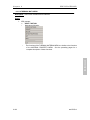
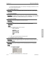
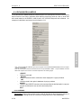
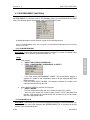
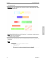
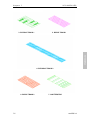
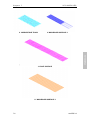
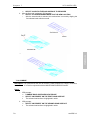
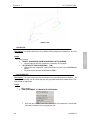
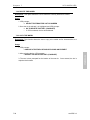
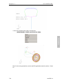
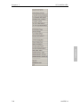
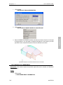
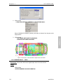
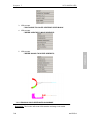
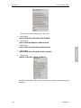
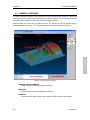
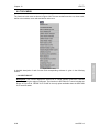
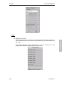
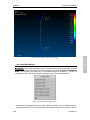
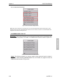
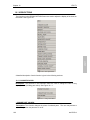
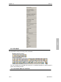
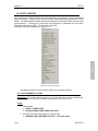
The user generates the desired road surface by selecting it from the ROAD SURFACE MENU.
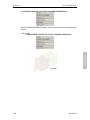
If the road surface is not in the correct position in relation to the suspension after generation,
the MOVE ROAD SURFACE command is used to position it.