1
eta/VPG
USER'S PROCESSOR
MANUAL
An LS-DYNA Based Full-Vehicle
Simulation Solution Package.
VPG Version: 1.1
Manual Release Date: June 15, 2000
FORWARD
The concepts, methods, and examples presented in this text are for illustrative and educational purposes only, and are not intended to be exhaustive or to apply to any particular
engineering problem or design.
This material is a compilation of data and figures from many sources.
Engineering Technology Associates, Inc. assumes no liability or responsibility to any person or company for direct or indirect damages resulting from the use of any information
contained herein.
Engineering Technology Associates, Inc.
1133 East Maple Road, Suite 200
Troy, MI 48083
Phone:
Support:
Fax:
(248) 729-3010
(800) ETA-3362
(248) 729-3020
Engineering Technology Associates, Inc., ETA, the ETA logo, and eta/VPG are the
registered trademarks of Engineering Technology Associates, Inc. All other trademarks
or names are the property of the respective owners.
Copyright 2000 Engineering Technology Associates, Inc. All rights reserved
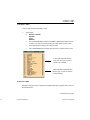
TABLE OF CONTENTS
INTRODUCTION ................................................................................................Section 1
Documentation .................................................................................. Section 1.1
eta/VPG History ................................................................................. Section 1.2
eta/VPG Methodology ....................................................................... Section 1.3
eta/VPG Software Package ................................................................. Section 1.4
eta/VPG Special Features ................................................................... Section 1.5
FEATURES AND FUNCTIONS OVERVIEW ................................................ Section 2
General ............................................................................................. Section 2.0
Pre Processor .................................................................................... Section 2.1
Post Processor .................................................................................. Section 2.2
Menu System .................................................................................... Section 2.3
Function Keys .................................................................................. Section 2.4
Display Window ............................................................................... Section 2.5
Mouse Functions .............................................................................. Section 2.6
Keyboard Entry ................................................................................ Section 2.7
Specifications ................................................................................... Section 2.8
Line Data .......................................................................................... Section 2.9
Conventions .................................................................................... Section 2.10
VPG File Menu .............................................................................. Section 2.11
Recommended Naming Convention .............................................. Section 2.12
LS-DYNA Cards ............................................................................ Section 2.13
Local Coordinate System ............................................................... Section 2.14
Entity Selction ................................................................................ Section 2.15
GETTING STARTED ....................................................................................... Section 3
Opening/Creating an eta/VPG Database File ..................................... Section 3.1
Setting Up a VPG Model .................................................................... Section 3.2
MAIN MENU .................................................................................................... Section 4
FILE MANAGER .............................................................................................. Section 5
PRE-PROCESSOR ............................................................................................ Section 6
LINE ................................................................................................. Section 6.1
SURFACE OPTIONS ...................................................................... Section 6.2
ELEMENT OPTIONS ..................................................................... Section 6.3
NODE OPTIONS ............................................................................. Section 6.4
MODEL CHECKER ........................................................................ Section 6.5
SET MENU (LS-DYNA) ................................................................. Section 6.6
SET MENU (NASTRAN)................................................................ Section 6.7
BOUNDARY CONDITIONS (LS-DYNA) ..................................... Section 6.8
BOUNDARY CONDITIONS (NASTRAN) ................................... Section 6.9
MATERIAL PROPERTY (LS-DYNA) ......................................... Section 6.10
MATERIAL PROPERTY (NASTRAN) ....................................... Section 6.11
ELEMENT PROPERTY ................................................................ Section 6.12
CONTACT INTERFACE .............................................................. Section 6.13
DYNA MISCELLANEOUS .......................................................... Section 6.14
SUPER ELEMENT ........................................................................ Section 6.15
VPG MODULES ............................................................................................... Section 7
ROAD MENU .................................................................................. Section 7.1
SUSPENSION MENU ..................................................................... Section 7.2
TIRE MODEL ................................................................................. Section 7.3
ANALYSIS EXECUTION ................................................................................ Section 8
RUN ANALYSIS ............................................................................. Section 8.1
RESTART ........................................................................................ Section 8.2
POST PROCESSING ........................................................................................ Section 9
FATIGUE ......................................................................................... Section 9.1
POST PROCESSING ....................................................................... Section 9.2
GRAPH ............................................................................................ Section 9.3
UTILITY.......................................................................................................... Section 10
VIEWING OPTIONS..................................................................... Section 10.1
VIEWING OPTIONS WINDOW .................................................. Section 10.2
PART CONTROL .......................................................................... Section 10.3
SETUP DEFAULTS ...................................................................... Section 10.4
UTILITY ........................................................................................ Section 10.5
DISPLAY PARAMETER OPTIONS WINDOW .......................... Section 10.6
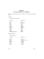
APPENDIX.......................................................................................................................
VPG Capabilities for F.E.A. Analysis Programs ............................................ A
VPG Hardware and Software Requirements .................................................... B
Supported IGES Entity Types .......................................................................... C
Converting RADIOSS to LS-DYNA .................................................................D
Converting LS-DYNA to RADIOSS ................................................................. E
Converting NASTRAN to LS-DYNA ............................................................... F
Converting LS-DYNA to NASTRAN ............................................................... G
Converting RADIOSS to NASTRAN ...............................................................H
Converting NASTRAN to RADIOSS ................................................................ I
Converting ADAMS to LS-DYNA .................................................................... J
VPG Menu ........................................................................................................K
FUNCTION INDEX ...........................................................................................................
Engineering Technology Associates, Inc.
Creation Date: December 15, 1998
Revision Level: 5
Revision Date: November 2, 2000
Approved by: Bruce Morse
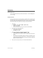
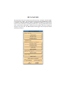
Introduction
1.1 DOCUMENTATION
The User’s Manual consists of two volumes of documentation for the eta/Virtual Proving
Ground (eta/VPG) software package; one for the Solver and one for the Processor. This
manual documents the pre- and post-processing portion of the eta/VPG integrated program
which was created to complete the following objectives:
1.
2.
3.
4.
To provide a general purpose pre- and post-processor for constructing FEA models and
reviewing analysis results.
To provide utility modules for meeting VPG specific application requirements such as a
tire model generator, a road surface library, a suspension model library, fatigue life
prediction program and FFT post-processor.
To allow the user to create and retain user-defined modules and libraries for road surfaces, material models, fatigue life prediction modules, control modules, etc.
To interface with the solver, a specialized, double precision, version of the LS/DYNA
Explicit and Implicit code.
Please reference the eta/VPG User’s Manual - Solver, an integral part of the User’s Manual,
for analysis related usage. The eta/VPG User’s Manual - Solver is a version of the LS/
DYNA User’s Manual Keyword Format (versions later than LS-940 Release).
The eta/VPG Applications Manual documents applications of the features and functions
included in the User’s Manual. Examples are provided to demonstrate the different techniques used in creating a VPG simulation. The Applications Manual also serves as a Training Manual for new users to gain experience with VPG techniques, methodology and code.
1.2 eta/VPG HISTORY
eta/VPG evolved in the mid 90’s with the advent of faster computers, cost effective hardware, advanced software technology, the ability to perform event-based simulations and the
need to overcome the limitations of existing CAE methodology. Conventional CAE techniques required smaller, specific analyses tailored to a specific task (such as NVH) and
fractured from the global analysis of the automotive system. The eta/VPG developers were
faced with the need for an integrated analysis that included both component level and full
vehicle applications with the ability to perform real-time simulations. The analysis would be
dynamic and nonlinear unlike the static, linear analysis techniques utilized by existing CAE
practices.
Introduction
Section 1 Page 7
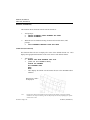
ETA first tested this concept on a simple mechanism simulating an engine connecting rod,
piston and crank shaft subsystem. The rigid body (piston and crankshaft) and flexible body
(connecting rod) were combined for stress and strain evaluation of the connecting rod during a combustion event.
The engine combustion event was simulated as a dynamic, nonlinear event in real time and
the results demonstrated that the motion and forces derived from the VPG simulation were
the same as the rigid body linkage motion simulation results produced from a conventional
rigid body linkage code. The benefit of obtaining realistic stress and strain results of the
connecting rod from VPG simulation, in an event based fashion, produced valuable analysis data that could not be generated in traditional FEA approaches.
Additional studies of chassis/suspension mechanisms and/or linkage subsystems using flexible body approaches were performed and the results proved that the time domain solution
was feasible. It also revealed that VPG’s great potential was yet to be developed.
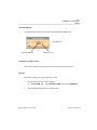
ETA engineers moved another step forward by simulating a rotating tire impact in a pothole
event. A tire model was developed to include the mass flow rate technique to account for
the tire air pressure variation in an impact condition. The simulation of the frictional contact of the tire model with the rigid road surface was extremely realistic and correlated with
existing tire data.
At the same time, Arthur Tang had an opportunity to view a video of MGA Proving Ground,
a full services vehicle proving ground located in Burlington, Wisconsin, owned and operated by MGA Research Corporation. He suggested that the road surface profiles could be
digitized from the proving ground construction drawings in a CAD surface format. FEA
mesh could be generated from the CAD surface data and produce a selection of generic
road profiles representing the characteristics of the proving ground testing conditions.
Arthur Tang presented his ideas to Dr. Pat Miller at MGA Research Corporation and obtained his approval to use the MGA Proving Ground Road Profile to try the VPG approach.
A tire model, including simulated tire pressure using the mass flow rate approach, was
placed on an MGA FEA road surface and rotated across a pothole impacting the front leap
of the pothole. The rotating motion of the tire matched existing event data; the virtual proving ground concept was established.
Since, 1995 ETA has moved VPG development work into high gear. Tim Palmer has led
ETA’s Applications Group in performing a number of serious full-vehicle VPG projects.
VPG work has been performed for, Ssangyang W1, Mack Truck Cab-in-White, Daewoo V100 and M-100, Chrysler CCV and Hyundai Precision SUV. ETA has also provided supSection 1 Page 8
Introduction
port to the Ford WIN126 pilot feasibility study project and the GM Small Car Division’s
effort to evaluate the VPG concept.
After two years of development and evaluation, it was confirmed that VPG technology could
produce repeatable, reliable and correlatable analysis results. The level of confidence from
users and correlation results lead to aggressive simulation use and requirements. As a result
of such requirements, the enhancement of eta/VPG’s current solver technology became necessary.
Dr. John Hallquist, at Livermore Software Technology Corporation (LSTC) accepted the
challenge of implementing various features and functions in LS/DYNA to meet VPG requirements.
In mid 1997, ETA and LSTC evaluated all the facts related to VPG technology and decided
to produce a software product, eta/VPG, coupling the existing LS/DYNA and eta/FEMB to
form a niche application code for VPG technology.
In January of 1998, eta/VPG version 1.0 was released to ETA’s Applications Group for use
in final feasibility studies and production projects supporting Chrysler’s CCV program, Ford’s
WIN126 program, and the GAZ 3111 program.
A VPG Users’ Meeting was called in March 1998 to collect and better understand user requirements. Based on the user input, development goals and key features and functions of
the code were finalized and eta/VPG Version 2.0 was ultimately released in August of 1998.
1.3 VPG METHODOLOGY
Virtual Proving Ground (VPG) is a general term used to reference a simulation methodology
using the tire and proving ground road surface approach. VPG technology is also referenced
as CAE Proving Ground, Analytical Proving Ground (by Ford users) and Virtual Road (by
Chrysler users).
The VPG method is a set of techniques used with an explicit, nonlinear, dynamic analysis
program which allows for the complete analysis of a mechanical system, including all joints,
bushings, material and geometric non-linearities using an event based analysis. The class of
problems targeted are those in which a mechanical system is to be analyzed in a dynamic
sense. In other words, when a mechanical system is in use, the displacement, forces, accelerations and stresses occur in real time. The VPG method allows for the calculation of all of
these quantities simultaneously, using a single analysis run.
Introduction
Section 1 Page 9
While VPG methodology was initially developed for full vehicle simulations based on a
proving ground durability cycle, the concept can also be applied to other dynamic mechanical systems.
1.4 eta/VPG SOFTWARE PACKAGE
eta/Virtual Proving Ground (eta/VPG) is a fully integrated, dynamic, nonlinear, finite
element software package used to create, analyze, edit and visualize dynamic nonlinear
engineering problems. The software includes an integrated preprocessor, post processor,
and solver. It is a complete CAE tool for applying theory and engineering principals
common in areas of mechanical and structural engineering. eta/VPG provides a single
package for use in analysis of multi-body dynamics problems, linear static, nonlinear static,
and dynamic nonlinear finite element analysis.
eta/VPG's strength lies in its ability to integrate problems that are treated as multi-discipline
by other software packages. eta/VPG allows the user to combine multi-body dynamics problems with structural finite element analysis problems, providing real time kinematics or dynamics, as well as the stress or strain response of the structure in real time.
eta/VPG consists of three primary modules, the Pre processor, Post Processor and Solver
modules. The Pre and Post Processor are general purpose, full feature and capability, and
contain a set of VPG utility modules for efficient model generation and analysis. The Solver
module is a double precision version of LS/DYNA, developed and marketed by Livermore
Software Technology Corporation (LSTC). LS/DYNA has both explicit and implicit solvers
that are seamlessly switched through a “restart function”.
eta/VPG’s multiple specialty features, designed specifically for full vehicle analysis, allow
for easy modeling, analysis and post processing of the results in a user-friendly environment.
Joints and bushings, finite element meshes, boundary conditions, materials, properties, suspension system components, tire and road surface libraries are all easily defined. The graphic
user interface allows for the generation of these models as well as the animation and evaluation of the analysis results.
1.5 eta/VPG SPECIAL FEATURES
eta/VPG was designed with unique features specifically for virtual proving ground simula-
Section 1 Page 10
Introduction
tions which do not exist in other general purpose pre- and post-processors. The development
of these features and functions was necessary to satisfy the following VPG requirements:
1.
2.
3.
4.
5.
Generation of complicated full vehicle/full system models and retention of complex nonlinear material properties, contact definitions, etc.
Generation and retention of user defined libraries and modules such as a tire library,
proving ground road surface library and driver control modules, etc.
Post-processing of huge amounts of analysis data (displacement, forces, acceleration,
stress and strain) derived from time domain solution of multiple events and the conversion from time domain results into frequency domain results (frequency, mode shape
and PSD, etc.).
Post-processing of stress and strain results of multiple events and the conducting fatigue
life prediction.
Development of chassis/suspension models and conducting of post-processing to evaluate the chassis/suspension design characteristics.
The key modules and libraries are briefly described below:
LS-DYNA 940 Interface Module
eta/VPG incorporates a complete, direct LS-DYNA 940 interface. eta/VPG reads and writes
all LS-DYNA 940 cards eliminating the need for text editing of the input deck. Create and
retain all material nonlinear properties, contact definition and loading conditions.
Tire Model Generator
eta/VPG’s tire model generator allows for easy construction of tire models. The tire model
generation tool employs specific tire geometry and inflation pressure to automatically
construct a three-dimensional finite element model. Tire models are used for both vehicle
durability and NVH applications.
Suspension Model Generator
eta/VPG's sophisticated suspension model generator automates the FEA modeling of the
most popular suspension types. Suspensions may be modeled using flexible, finite element
representations or rigid members. Material properties of the suspension component can be
specified using nonlinear stress-strain characteristics of the material. Included in eta/
Introduction
Section 1 Page 11
VPG’s suspension library are these suspension types:
MCPHERSON H-ARM
MCPHERSON A-ARM
SOLIDAXLE
FIVE LINK
QUADRA LINK
T RAILING ARM
HOTCHKISS
T WIST BEAM
HONDA 5-LINK
SHORT LONG ARM
Road Surface Library
eta/VPG’S road surfaces form a full vehicle durability evaluation platform ready for
kinematics and stress analyses of component, subsystem, and vehicular models. Road
surfaces are generated using any 3D data or selected from the VPG library, W hich contains
digitized models of MGA Proving Grounds such as:
POTHOLE TRACKS
ALTERNATE ROLL SURFACE
COBBLESTONE T RACKS
BODY TWIST LANE
R IPPLE TRACKS
WASHBOARDS
C HATTERSTRIP
P AVED SURFACE
Fatigue Analysis Program Module
eta/VPG’s built in post processor automatically performs fatigue life analysis prediction to
identify the key damage events and stress amplitudes. This data is then used to calculate
the percentage of fatigue life remaining at the completion of the durability cycle. eta/VPG
displays these results in easily read, combined fatigue life contour plots.
Signal Processing Module
eta/VPG performs full vehicle NVH studies on simulated proving ground surfaces. eta/
VPG automatically converts time domain analysis results into frequency-domain via FFT
(Fast Fourier Transform). eta/VPG determines both low and mid range frequencies up to
250Hz for operating mode shapes, frequencies, structural and airborne noise and frequency
responses such as idle shake, rough road, power train and wheel unbalance.
Section 1 Page 12
Introduction
Features and Functions Overview - Processor
2.0 GENERAL
The eta/VPG Processor has a complete graphic user interface that is operated on UNIX
based workstations (W/S) including IBM, HP, SUN, DEC-Alpha and SGI platforms using
various popular operating systems. The model generation, input file preparation, and
results processing activities are all done in a W/S environment. The solution, either explicit
or implicit, can be executed on both local W/S and/or remote server systems.
The graphic package requires PHIGS Library to operate. The program is organized as a
“tree structure” and operated and controlled by a MOTIF Graphic User Interface (GUI).
The operator can either activate the functions via mouse pick and/or key in the commands
via keyboard entry. The function keys are also available for the operator to quickly move
between main menus.
2.1 PRE PROCESSOR
eta/VPG’s extensive Preprocessing capabilities contain all the functions necessary for
expedient, high quality modeling. Users can read in data with VPG’s CAD interface, build
their model from scratch, read in an existing model, or a combination of the approaches.
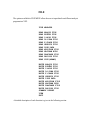
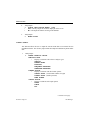
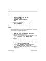
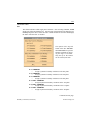
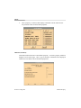
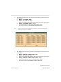
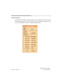
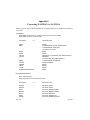
CAD Interface
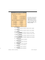
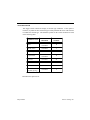
eta/VPG enables users to quickly read in geometry data in IGES format from any
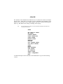
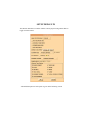
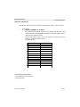
CAD system. Supported IGES entity types include:
Name
Type
Null Entity
Circular Arc Entity
Composite Curve Entity
Conic Arc Entity
Copious Data Entity
Plane Entity
Line Entity
Parametric Spline Curve Entity
Parametric Spline Surface Entity
Point Entity
Ruled Surface Entity
Surface of Revolution Entity
Tabulated Cylinder Entity
Transformation Matrix Entity
0
100
102
104
106
108
110
112
114
116
118
120
122
124
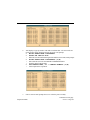
Continued on next page.
Features and Functions
Section 2 Page 13
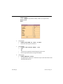
Rational B-Spline Curve Entity
Rational B-Spline Surface Entity
Offset Surface Entity
Boundary Entity
Curve on a Parametric Surface Entity
Bounded Surface Entity
Trimmed ( Parametric ) Surface Entity
Subfigure Definition Entity
Associativity Instance Entity
Property Entity
Singular Subfigure Instance Entity
126
128
140
141
142
143
144
308
402
406
408
For the German automotive industry, VDA file format is supported. Supported
VDA entity types include:
POINT
CIRCLE
CURVE
SURF
CONS
FACE
VPG also supports line/surface data from PDGS and CGS via an external
translator.
If CAD data is not available, eta/VPG has a complete geometry and surface
building capability, which acts as an integrated CAD data generator.
Extensive Model Building Functions
eta/VPG includes a comprehensive selection of functions for creating and
modifying line data and CAD surfaces. Element generation through 2-line, 4-line,
6-line and 8-line mesh creates beam, shell and solid elements.
-Comprehensive Model Modification Functions
-Full System Assembly
Automeshing
eta/VPG’s automeshing function easily eliminates 90% of the time required to
mesh trimmed and standard IGES surfaces. The automeshing function creates
quadrilateral elements with a minimum of triangular elements.
Section 2 Page 14
Continued on next page.
Features and Functions
Material/ Element Properties
eta/VPG supports all LS-DYNA material and element property cards. eta/VPG’s
ability to create and assign material and element properties directly on a displayed model greatly reduces the amount of editing required. Definition cards
appear at specific junctions in the session prompting the user for material/
element properties. Users also have the option to specify an analysis code
(NASTRAN, LS-DYNA) prior to assigning properties.
Contact Interface
eta/VPG seamlessly interfaces with LS-DYNA allowing the user to create and
assign impact, sliding, or automatic interfaces for VPG applications. eta/VPG
displays contact properties in easily read and modified CONTACT CARDS with
a high degree of speed and flexibility.
Boundary Conditions
eta/VPG’s BOUNDARY CONDITIONS menu allows the user to quickly create
and verify constraints and loads on VPG models.
Extensive Model Integrity Checking Functions
The functions in eta/VPG’s MODEL CHECKER menu quickly validate models
for element orientation, size, skew, connectivity, and interior angles. Model
validation default values are easily adjusted to suit the user’s needs.
Constraints
eta/VPG supports all LS-DYNA Constraint Cards for quick, easy definition and
manipulation of joints, welds, rivets, etc.
2.2 POST-PROCESSOR
VPG integrates a general purpose, full feature and capability post-processor for complete
post processing within the single-code, workstation environment. Analysis results are
seamlessly input from VPG’s double precision LS-DYNA solver to the post processor for
quick, easy interpretation of analysis results. Once entered, VPG’s full complement of
post processing functions allow the user to graphically display and manipulate solver code
result files with contour and deformation animation, contour plots and fills, and geometry
deformation.
Continued on next page.
Features and Functions
Section 2 Page 15
VPG’s post processing functions allow the user numerous ways of animating and viewing
the analysis results. The user has the options of animating select frames, viewing single
frames, altering the time step, rotating the model, or viewing only select parts, of the
model.
To utilize the post processing functions, users generate a result file with the suffix .pp (post
processing). The .pp file is generated by reading a result file into the post processor. The
post processing function automatically prompts the user for the result file when activated.
VPG post processes the following types of result data:
D3PLOT (d3plot01, etc.)
NASTRAN PUNCH (.pch)
DYNA DEFORMED GEOMETRY (.defgeo)
NASTRAN PACKED PUNCH (.pac)
HISTORY (.his)
Once the .pp file is created it is recommended that the user save it. It requires less space
than the analysis result file used to create it and can be used for all subsequent post
processing functions. It also requires significantly less time to load the .pp file. Once, the
.pp file is created, the file used to generate it can be deleted (in most cases).
FATIGUE
VPG allows the user to generate and post process fatigue result files from within
the VPG interface.
ANIMATE CONTOUR
This function is used to map the stresses, strains and strain energy of the model
across time. Animations can be edited to even, odd, or specified frames.
ANIMATE DEFORMATION
This command allows the user to animate displacements within the model in real
time. Animations can be edited to even, odd, or specified frames.
CONTOUR FILL
This function maps stresses, strains, and strain energy in the model for a single
step. It allows the user to view the contour values by superimposing a fill-color
contour image onto the model.
The values are displayed in a color legend in the upper right hand corner of the
screen.
Continued on next page.
Section 2 Page 16
Features and Functions
CONTOUR LINES
This function, similar to the CONTOUR FILL function, allows the user to check
the model’s contour values for a single step. A color, wire frame, contour-line
plot of the component result is superimposed onto the current model.
DEFORMED SHAPE
This command displays the displacement results of the model for a single step.
The undeformed model shape is displayed in white. The model can be animated
to show the transition between the undeformed and deformed model.
ELEMENT STRESS
This function displays the stress results of each individual element as opposed to
the contour plot functions which display the stress results in terms of the average
stress at each node. A color legend for the corresponding color values is displayed
in the upper right hand corner of the screen.
TIME HISTORY PLOT
eta/VPG's TIME HISTORY PLOT functions enable the user to visualize the
results of an analysis with XY plots. VPG offers a wide range of tools to
manipulate the information on the display screen with labels, colors, multiple
graphs, and a host of advanced filtering techniques e.g., FIR, Butterworth, SAE,
scaling, smoothing, and averaging.
FFT (FAST FOURIER TRANSFORM
The TIME <-->FREQUENCY function allows the user to convert time domain to
frequency domain response for signal processing analysis. The FFT equation is
used to convert time domain to frequency domain and frequency domain to time
domain for any graph plot.
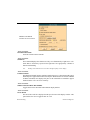
2.3 MENU SYSTEM
The program starts in the MAIN menu (see figure on page 20) and branches out into submenus. The user selects a sub-menu by mouse pick or keyboard entry. Descriptions for
these menu options are located in their respective sections.
FILE
Imports and exports data to and from VPG.
Continued on next page.
Features and Functions
Section 2 Page 17
PREPROCESSOR
LINE
SURFACE OPTIONS
ELEMENT OPTIONS
NODE OPTIONS
MODEL CHECKER
SET MENU
BOUNDARY CONDITIONS
MATERIAL PROPERTY
ELEMENT PROPERTY
CONTACT INTERFACE
DYNA MISCELLANEOUS
SUPER ELEMENT
ROAD MENU
SUSPENSION MENU
TIRE MODEL
ANALYSIS
FATIGUE
FFT
POST PROCESSING
GRAPH
RESTART
SESSION FILE
Contains a menu of preprocessing functions.
Creates and modifies line/surface data.
Creates and modifies surfaces in VPG.
Creates and modifies elements.
Creates, copies, transforms, and manipulates nodes.
Checks element criteria (warpage, boundary, aspect ratio, etc.).
Creates node and element sets for
superelement files and substructure files,
etc.
Creates and verifies constraints and loads
on a finite element model.
Creates and assigns material properties.
Creates and assigns element properties.
Creates and modifies sliding/rigidwall
interfaces for LS-DYNA.
Handles distinct LS-DYNA miscellaneous
data.
Assigns and modifies SUPERELEMENT ID
numbers (only for NASTRAN application).
Defines road surfaces.
Defines and auto-generates front and rear
automotive suspensions.
Defines and auto-generates tire models.
Analyzes proving ground events.
Analyzes element fatigue.
Provides signal processing.
Provides options for viewing the results of
an analysis.
Plots dynamic characteristics of the
structure vs. time, velocity, etc.
Restarts a current VPG session with a
current or another database.
Regains lost work (e.g., after a system
Continued on next page.
Section 2 Page 18
Features and Functions
VIEWING OPTIONS
EXIT PROGRAM
crash) lost during a VPG session.
Manipulates the display, position, and
perspective of a model.
Exits VPG.
2.4 FUNCTION KEYS
Function keys 1 through 8 direct the user to the most frequently used menus. The F1
(function key 1) is reserved for the Main Menu.
F1
F2
F3
F4
Main Menu
Element Option
File
Line
F5
F6
F7
F8
Model Checker
Node Options
Surface Options
Free Rotation
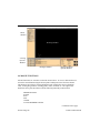
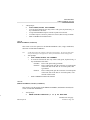
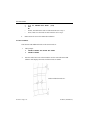
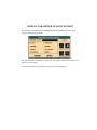
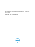
2.5 DISPLAY WINDOW
VPG breaks the screen into five distinct regions. The regions are used to receive input or
display messages for the user. The five regions are illustrated on the following page.
1. DRAWING WINDOW -- Models and definition cards are displayed in this
area.
2. VIEWING OPTIONS WINDOW-- This group of commands dynamically
manipulate the display, position, and perspective of a model.
3. MENU WINDOW -- Commands and command options are displayed in this
area. They can be accessed via the keyboard mouse.
4. DIALOGUE WINDOW -- VPG displays comments and messages to the user
and accepts keyboard entry commands in the dialogue window.
5. DISPLAY PARAMETER OPTIONS WINDOW -- These commands set the plot
options for the current model.
Continued on next page.
Features and Functions
Section 2 Page 19
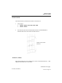
Menu
Window
Drawing Window
Viewing
Options
Window
Dialogue Window
Display Parameter
Options Window
2.6 MOUSE FUNCTIONS
All VPG functions are accessible via the left mouse button. To access a function the user
selects the desired button using the mouse pointer and depresses the left mouse button.
This button is also used for selecting definition cards, locating the cursor in definition
cards, creating drag windows, locating points, nodes, elements, etc. The right mouse
button activates a pull-down menu with the following commonly used functions:
FREE ROTATION
ZOOM
PAN
FILL
CLEAR
ACTIVE WINDOW ON/OFF
Continued on next page.
Section 2 Page 20
Features and Functions
VIRTUAL - X ROTATION
VIRTUAL - Y ROTATION
VIRTUAL - Z ROTATION
SCREEN ROTATIONS
FIXED VIEWS
NODE OPTIONS
ELEMENT OPTIONS
GEOMETRY BUILDER
2.7 KEYBOARD ENTRY
To increase speed and efficiency all VPG functions can also be accessed by keystroke
entry. Entering a one or two-letter combination followed by the return key activates each
command of the menu that the user presently has on the screen. For main menus, the letter
combination is the first two letters of a one word command or the first letter of each of the
first two words of a two or more word command. For example, the keystroke entry for the
command FREE ROTATION in the above menu would be “f”, “r” followed by the
RETURN key. As the user types the keys, the matching command will be highlighted.
For the ZOOM command, the keystroke entry would be “z”, “o” followed by the RETURN key. For control keys, the user need only type the first letter to access the function.
2.8 SPECIFICATIONS
The standard version of VPG has the following specifications for UNIX based workstations per database (VPG-Large is available to handle extra-large models):
150,000
200,000
4,000
125,000
125,000
1,000
1,000
Features and Functions
LINES
POINTS
SURFACES
-200,000 Edge Points (SURFACE)
-400,000 Control Points (SURFACE)
GRIDS
ELEMENTS
PROPERTIES
PIDS
Section 2 Page 21
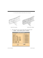
2.9 LINE DATA
VPG's built-in translator converts and filters line data from the following programs into a
neutral line format:
IGES (line and surface)
CGS (DES, INCA)
DXF file formats and
PDGS (standard format)
VDA file
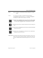
2.10 CONVENTIONS
This manual is designed to reduce the amount of reading material on the page and maintain
text clarity. Several fonts and symbols are implemented throughout the manual. An
example is given at the bottom of the page.
FIXED FONT
(ALL CAPS, BOLD)
This font indicates text found within VPG e.g., menu
names, subsections, commands, and options within
commands, etc.
Proportional Font
This font indicates explanatory text e.g., command
descriptions, notes, and section titles.
ALL CAPITALS
This font indicates a function, menu name, card,
command, etc. found in explanatory text.
>
The greater than symbol directs the user to read the
text displayed in VPG’s DIALOGUE WINDOW.
?
The question mark directs the user to select an option
that is listed in VPG’s MENU WINDOW.
•
The bullet signals a description of the previous
command or situation.
Section 2 Page 22
Features and Functions
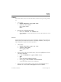
-CREATE
4 - PLATE ELEMENT
This section covers the options for the PLATE ELEMENT subsection of
CREATE ELEMENTS.
1.
VPG prompts:
>
PICK NODES/POINTS FOR ELEMENT
?
NODE
POINT
•
To create the elements the user may select a node, point, keyboard entry, or any combination of the three.
•
An element will be created after three or four nodes/points are
selected.
•
EXIT or ABORT will exit this function.
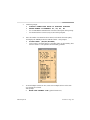
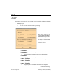
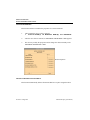
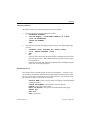
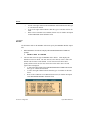
2.11 VPG FILE MENU
The VPG FILE MENU allows users to easily access files and directories. The DIRECTORIES and FILES windows are accompanied by scrollbars and the VPG FILE MENU
window is expandable for easy viewing of directories and files.
Features and Functions
Section 2 Page 23
All files listed in the FILES window are displayed from the current directory based on the
filter (filename extension such as .vpg). The current directory is listed at the bottom of the
DIRECTORIES window. The filter is set by changing the filter parameter in the FILTER
window and clicking the filter button. The SELECTION window allows the user to enter
the file name and directory manually.
2.12 RECOMMENDED NAMING CONVENTION (.his, .lin, .bin, etc.)
The protocol for naming files during a VPG session includes attaching suffixes to the file
names which specify the file types.
Examples of suffixes include:
1.
Section 2 Page 24
VPG database file name:
filename.vpg
Features and Functions
2.
3.
4.
5.
6.
7.
NASTRAN file name:
VPG line data file name:
VPG binary database file name:
VPG binary result file name:
LS-DYNA database:
LS-DYNA history result file:
filename.dat
filename.lin
filename.bin
filename.pp
filename.dyn
filename.his
Example: When reading in a line data file, VPG prompts for a line data file name (all file
names in that directory with the suffix .lin are listed in the options area). The user then
selects the appropriate file name. This practice makes the file name selection conve
nient and organizes the user's work directory.
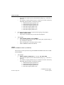
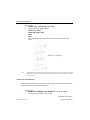
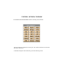
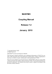
2.13 LS-DYNA CARDS
eta/VPG supports all LS-DYNA cards. As a result, card definition requires no text
editing. The cards are arranged as they are in the LS-DYNA manual. eta/VPG displays the
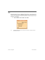
cards in the conveniently edited window seen on the opposite page and described below.
CARD SELECT BUTTON
The CARD SELECT BUTTON displays the number of definition cards and allows
the user to jump conveniently to the desired card. The card button is not an option
when only one card is needed to define the selected property or the number of cards
is dependent on user defined values.
CARD DESCRIPTION FIELD
The CARD DESCRIPTION FIELD allows the user to enter a name for the defined
properties.
EDITING FIELD
VPG's smart editing field only allows values within the specified range to be entered. If the value entered is beyond the LS-DYNA defined range VPG prompts the
user when the user tries to move to another field or card.
Features and Functions
Section 2 Page 25
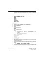
Card Title
Card Select Button.
Card Description
Field
Editing Field
Field Description
Editing Push
Button
FIELD DESCRIPTION
The field description indicates the value to be added to the editing field. If the field
description text is gray, it means that the value entered in that field is dependent on
another field which must be edited first.
EDITING PUSH BUTTON
An editing button forwards the user through a series of prompts, menus, or cards
which results in a valid value for the chosen field.
OK
Accepts and saves the defined card.
NEXT
Forwards the user to the next card.
PREVIOUS
Forwards the user to the previous card.
CANCEL
Exits without saving or defining the card.
ENTER
Pressing ENTER at any time during card definition accepts and saves the defined
card.
Features and Functions
Section 2 Page 26
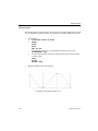
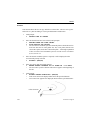
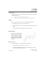
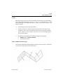
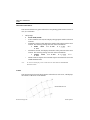
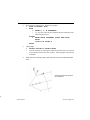
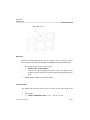
2.14 LOCAL COORDINATE SYSTEM
VPG refers to the local coordinate system to translate, rotate, mirror, copy, and generate
points, lines, or nodes. When such a function is selected, the program will automatically
prompt the user to generate a local system designated as the UVW coordinate frame.
Either one, two, or three reference points are required to establish a local coordinate
system. For a three point system, the first reference point defines the local origin. The
second reference, which extends from the first reference point, defines the direction of the
local U-axis. The third reference point defines the local UV plane. The local W-axis is
defined in the UV plane and is perpendicular to the U-axis. The local W-axis is then
defined according to the right hand rule perpendicular to the UV plane.
For the two reference point option, DONE should be selected after the second reference
point is defined. The local W-axis lies along the vector from the origin to the second
reference point; the V-axis lies in the VW plane; and the U-axis is defined by the right
hand rule.
note:
All rotational commands (generating arcs, copying with rotation, etc.) are executed about
the local W- or global Z-axis.
For a one reference point option, the user selects a point or node on the screen as the local
origin, then enters one of the X, Y, or Z options that are listed to define the local W along
one of the global axes.
note:
1.
Defining a local coordinate system with "one" reference point is described
in the following text and marked with “•.”
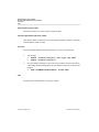
When creating a local coordinate system, VPG prompts:
>
CREATE LOCAL COORDINATES
PICK NODE/PT FOR ORIGIN
•
VPG prompts for a desired coordinate system (local or global) in the
options area.
?
ABORT
GLOBAL SYSTEM
KEY IN X, Y, Z
•
This signals the user to key in the origin of the local coordinate system.
>
ENTER X, Y, Z COORDINATES
Features and Functions
Section 2 Page 27
•
The user enters the values for the X, Y, and Z coordinates, e.g.,
100,0, and 0.
NODE
•
Default
POINT
SHOW LAST C.S.
•
Once the last coordinate system has been displayed, see step 3.
•
The user may select a node or a point, enter a coordinate by key
board, or use any combination of these options to create a local
coordinate system.
2.
Once a reference point has been selected, VPG prompts:
>
PICK NEXT POINT OR NODE
?
ABORT
DONE
•
After the user selects 2 reference points, VPG displays the coordinate system and continues to step 4.
KEY IN XYZ
•
The user may enter up to 3 reference points globally to define a
local coordinate system.
INCREMENTAL XYZ
•
The user may enter DX, DY, and DZ from the previous reference
point to define a local coordinate system.
NODE
•
The user may select up to 3 nodes to define a coordinate system.
POINT
•
The user may select up to 3 points to define a coordinate system.
REJECT LAST
•
This allows the user to deselect the last reference point during the
selection process.
X AS LOCAL W AXIS
•
This defines a local coordinate system that is parallel to the global
axis with the local W along the global X-axis and the local origin at
the first reference point.
Y AS LOCAL W AXIS
•
This defines a local coordinate system that is parallel to the global
axis with the local W along the global Y-axis and the local origin at
the first reference point.
Section 2 Page 28
Features and Functions
Z AS LOCAL W AXIS
•
This defines a local coordinate system parallel to the global axis
with the local W along the global Z-axis and the local origin at the
first reference point.
3.
Once the user defines the desired coordinate system, VPG displays it and
prompts:
>
ACCEPT ? (Y/N/A)
?
YES
•
VPG prompts for the next command.
NO
•
The user returns to step 1.
ABORT
•
The user returns to the menu.
2.15 ENTITY SELECTION
In certain commands such as COPY, DELETE, etc., VPG prompts the user to select
elements, nodes, lines, surfaces, etc. A list of options will appear in the MENU WINDOW. The default selection option is cursor pick at the entity. Other commonly used
selection options are described below:
WINDOW
A window (drag-window) is defined by clicking the left mouse button, dragging the
cursor diagonally across the screen until the desired entities are within the window
and then clicking the left mouse button a second time to complete the selection. If
an entity is partially outside the window, it will not be selected.
MULTI-PT REGION
A multi-point region (polygon) is defined by clicking the left mouse button in succession to enclose the desired polygon region. Click on the right mouse button to
reject the last defined point. Click on the middle button to complete the region.
Entities within this region will be selected. If part of an entity is outside of the
region, it will not be selected.
PART
The part names will be listed in the menu area. Pick the name from the part list or
pick an entity from the screen to select the part. Selected parts will be highlighted in
white in the MENU WINDOW. All entities in the part will be selected.
Features and Functions
Section 2 Page 29
REJECT
This option negates the last selection whether from single cursor pick or a group of
entities selected by any of the above options.
EXCLUDE ON/OFF
This option works like a toggle switch. If turned on, all the subsequent selected
entities will be removed from the previously selected list. The user may toggle this
option on and off during the course of the selection.
TYPE
This option is used to control the type of elements to be selected. If DONE is
selected immediately after selecting TYPE, all elements of this type will be selected. Otherwise, other options may be used to limit the selection of elements.
note:
The TYPE function is specific to the selection of elements.
SURFACE
This function is used to select elements created from a surface by the SURFACE
MESH command.
note:
Section 2 Page 30
The SURFACE function is specific to the selection of elements.
Features and Functions
Getting Started
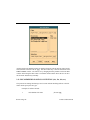
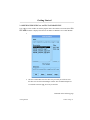
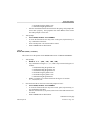
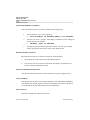
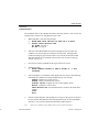
3.1 OPENING/CREATING an eta/VPG DATABASE FILE
Type ‘vpg’ in a Unix window to start the program. Once the windows are activated, the VPG
FILE MENU window is displayed for the user to OPEN or CREATE a new VPG database.
1.
2. The user would either select the name of a previously saved file or enter
the name of a new file in the Dialogue window. The recommended practice
is to add the extension .vpg to a newly created file.
Continued on the following page.
Getting Started
Section 3 Page 31
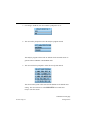
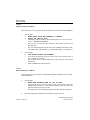
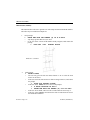
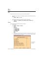
3. If creating a NEW file, the user would be prompted to do so:
4. The user will be prompted to select the analysis program desired:
The analysis program selected will set defaults for the eta/VPG session to
generate either LS/DYNA or NASTRAN cards.
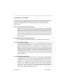
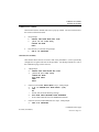
5. The user will also be prompted to select the Unit System desired:
The selected unit system will be stored in the database as the default value
setting. The user will now be in the MAIN MENU of eta/VPG and
ready to start the session.
Continued on next page.
Section 3 Page 32
Getting Started
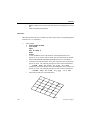
3.2 SETTING UP A VPG MODEL
Following is a general outline for setting up a VPG model. There are three unique modules
in the VPG pre-processor that allow the user to create a VPG model in an automated
procedure. A detailed description of each of these processes is available in the VPG
training manual.
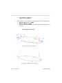
1- Auto-Generating a Front Suspension Model
The user begins by selecting a front suspension model from the SUSPENSION
MENU. The user determines the desired optional components such as stabilizers
and steering system types and enters the node coordinates for suspension geometry.
Next the user will be prompted to edit the default spring stiffness, damping coefficients, extra node coordinates, default mass, center of gravity and inertia moment.
Once the user has edited the default suspension values, the suspension will be displayed on screen.
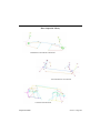
2- Auto-Generating a Rear Suspension Model
The rear suspension is generated in the same way that the front suspension is.
3- Auto-Generating Tire Models
After entering the TIRE MENU the user selects GENERATE and is offered the
TIRE PARAMETER dialogue box. Default values for tire geometry, mass and
inflation pressure are edited to the user's parameters. Once the tire geometry is
defined, VPG prompts the user for the location of the tire. The spindle of one of the
suspensions is selected and the tire is attached. The user then selects the other three
spindles in clockwise or counter-clockwise fashion and the remaining three tires are
generated and added to the model. Once the tires are defined, the user attaches them
to the suspension, defines airbags for tire pressure and defines the initial rotational
velocity of the tires.
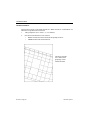
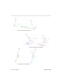
4- Auto-Generating a Road Surface
The user generates the desired road surface by selecting it from the ROAD SURFACE MENU. If the road surface is not in the correct position in relation to the
suspension after generation, the MOVE ROAD SURFACE command is used to
position it. Next, contact between the road surface and the tires is determined
using the FIVE_NODES_TO_SURFACE interface type. The road is then constrained in the Y, Z and rotational directions using material property assigned to
the road.
Next, a velocity is assigned to the road using the
BOUNDARY_PRESCRIBED_MOTION card.
Getting Started
Section 3 Page 33
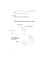
5- Reading the Simplified Body Model
The body to chassis/suspension attachment process depends upon what type of body
model the user wishes to use for analysis (deformable or rigid).
Rigid Body- The rigid body model is constrained to the rigid beams that define the
body attachment points on the suspension.
Deformable Body- The specific coordinates for the body attachments points must
be entered when the user defines the Extra Node Coordinates for the front/rear suspension models. This ensures that the generated suspension would fit the specific
body model. The user then creates weld spiders between the mounts on the vehicle
and the rigid body beams on the suspension.
Next the user defines the BODY_LOAD_DEFINITION_CARD to define the gravity.
After defining the gravity the user pre-loads the suspension using the ELEMENT
DEFINITION CARD.
6- Defining VPG Analysis Control Parameters
First, the CONTROL ENERGY and the CONTROL TERMINATION cards must
be defined. Next the output control interval data for the ASCII database must be
determined. Then the BINARY DATABASE cards must be edited to control the
output interval of the results and restarts.
7- Analysis Submission
From the ANALYSIS menu, select DYNA INPUT FILE OPTIONS, edit the dialogue box, and submit the analysis.
8- Displaying Results
When post-processing the analysis results, RESTART the eta/VPG session, and
CREATE A NEW FILE called ‘pp.vpg’- pp for post-processing.
Section 3 Page 34
Getting Started
Enter the POST PROCESSING menu and select D3PLOT (LS/DYNA result file).
Then select the analysis' ‘d3plot’ from the File Menu. Select LS/DYNA version
940. Select ALL AVAILABLE STEPS. Select ALL COMPONENTS
The results from each of the analysis steps will then be read into eta/VPG. A binary
result file will be created at this time (named ‘d3plot.pp’). Since the results are not
saved to the eta/VPG database, this binary file should be re-read into the postprocessing menu when the user wishes to view the results again. This file is read
much faster than the d3plot files.
The results are now ready to be post processed using a variety of features.
9- Graph Plotting
To graph the results, select GRAPH from the Main Menu. The user then has the
option of reading in a previously saved LS-DYNA ASCII graph file. When exiting
the GRAPH MENU, the user has an option to save the graphs in a binary file for
future processing. This file will be loaded mush faster than the LS-DYNA ASCII
files.
Continued on next page.
Getting Started
Section 3 Page 35
Section 3 Page 36
Getting Started
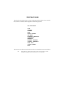
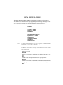
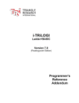
MAIN MENU
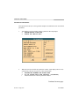
This is the first menu the user encounters when beginning a session with VPG. The initial
options unfold into an additional series of submenus. These submenus are documented in
the following sections.
MAIN MENU
FILE
PRE-PROCESSOR
ROAD
SUSPENSION
TIRE MODEL
ANALYSIS
FATIGUE
POST PROCESSING
GRAPH
RESTART
SESSION
VIEW
EXIT PROGRAM
Section 04 Page 38
Main Menu
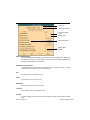
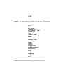
FILE
The options available in FILE MENU allow the user to input data from different analysis
programs into VPG.
FILE MANAGER
READ
READ
READ
READ
READ
READ
READ
READ
READ
READ
READ
READ
ABAQUS FILE
BINARY FILE
C-MOLD FILE
LS-DYNA FILE
F-CRASH FILE
GENESIS FILE
LINE DATA
MOLDFLOW FILE
NASTRAN BULK
PAMCRASH FILE
RADIOSS FILE
SUSP(ADAMS)
WRITE ABAQUS FILE
WRITE BINARY FILE
WRITE C-MOLD FILE
WRITE LS-DYNA FILE
WRITE F-CRASH FILE
WRITE GENESIS FILE
WRITE LINE DATA
WRITE MOLDFLOW FILE
WRITE NASTRAN BULK
WRITE PAMCRASH FILE
WRITE RADIOSS FILE
SUMMARY REPORT
VIEW
EXIT
A detailed description of each function is given in the following section.
READ ABAQUS FILE
READ BINARY FILE
READ ABAQUS FILE
VPG reads ABAQUS files directly with its built in translator. The VPG ABAQUS file
extension is .inp.
READ BINARY FILE
This function allows the user to read a VPG binary file (.bin) into VPG. The binary model
file contains only the finite element model data written by VPG. Any number of binary
files may be read in at any time during the VPG session. VPG allows the user to offset the
node/element numbers if the numbers have already been used in the database.
1.
VPG prompts:
>
READING VPG MODEL BINARY INPUT FILE
>
ENTER FILE NAME
•
The files with the suffix .bin will be listed in the VPG FILE MENU.
2.
If the file does not exist the prompt reads:
>
FILE DOES NOT EXIST
>
RE-ENTER OR STOP
3.
If the user is reading data into an existing model, VPG prompts:
>
OFFSET NODE AND ELEMENT NUMBERS? (Y/N)
•
YES renumbers the new data at the lowest available unused node/element
number.
•
NO compares the node/element numbers and ignores the duplicates--VPG
retains only the original nodes and elements (i.e., if the binary file contains all
duplicate node and element numbers, the new part will read in without the
presence of elements or nodes).
4.
VPG reads in the file and returns the user to the FILE MANAGER menu.
Section 4.1 Page 40
File Manager
READ C-MOLD FILE
READ LS-DYNA FILE
READ C-MOLD FILE
This function allows the user to read a C-MOLD (.fem) file directly into VPG.
1.
VPG prompts:
>
READING C-MOLD INPUT FILE
•
The files with the suffix .fem will be listed in the options area.
2.
After the user enters a filename, VPG prompts:
>
SI UNIT IS USED IN FEM FILE
>
SELECT UNIT TO BE USED IN VPG DATABASE
?
MM
CM
METER
IN
EXIT
•
This sets the measurement unit for the model.
3.
If the user is reading data into an existing model, VPG prompts:
>
OFFSET NODE AND ELEMENT NUMBERS? (Y/N)
•
YES renumbers the new data at the lowest available unused node/element
number.
•
NO compares the node/element numbers and ignores the duplicates--VPG
retains only the original nodes and elements (i.e., if the c-mold file has all
duplicate node and element numbers, the new part will read in without the
presence of elements or nodes).
4.
VPG reads in the file and returns the user to the FILE MANAGER menu.
READ LS-DYNA FILE
This function allows the user to read both keyword and non-keyword LS-DYNA (.dyn)
files directly into VPG. VPG supports versions 88 to 940 Keyword. Once the user has
entered the command, the files with the suffix .dyn will be listed in theVPG FILE MENU.
The user can then select the desired file.
File Manager
Section 4.1 Page 41
READ F-CRASH FILE
READ GENESIS FILE
READ LINE DATA FILE
READ MOLDFLOW FILE
READ F-CRASH FILE
This function allows users to read F-CRASH (.fcr) files directly into VPG. Once the user
has entered the command, the files with the suffix .fcr will be listed in the options area.
The user can then select the desired file.
READ GENESIS FILE
This function allows users to read GENESIS (.dat) files directly into VPG. Once the user
has entered the command, the files with the suffix .dat will be listed in the options area.
The user can then select the desired file.
READ LINE DATA FILE
This function allows users to read converted wireframe and IGES surface data into VPG.
In order to provide flexibility in accepting line data from different CAD systems, VPG
uses a neutral line data format to communicate with these CAD systems: IGES, PDGS
standard, CGS (INCA and DES), and DXF. Once the user has entered the command, the
files with the suffix .lin will be listed in the options area. The user can then select the
desired file.
note:
VPG MENU provides the necessary translators for the file types listed above. The
filter programs provided in the VPG MENU reduce the number of unnecessary
points in the CAD line data, combine duplicate lines, and join line segments into
continuous lines.
READ MOLDFLOW FILE
This function allows users to read MOLDFLOW data directly into VPG.
1.
VPG prompts:
>
READING MOLDFLOW INPUT FILE
>
ENTER THE ROOT NAME OF THE MOLDFLOW INPUT FILES
2.
After entering the root file name (assuming that the .mfl, .mod, and .tri
files are available) VPG displays the MOLDFLOW model.
3.
If the user is reading data into an existing model, VPG prompts:
Continued on next page.
Section 4.1 Page 42
File Manager
READ NASTRAN BULK
>
•
•
4.
OFFSET NODE AND ELEMENT NUMBERS? (Y/N)
YES renumbers the new data at the lowest available unused node/element
number.
NO compares the node/element numbers and ignores the duplicates--VPG retains only the original nodes and elements (i.e., if the MOLDFLOW file contains all duplicate node and element numbers, the new part will read in without
the presence of elements or nodes).
VPG reads in the file and returns the user to the FILE MANAGER menu.
READ NASTRAN BULK
VPG uses NASTRAN as a file translator so that the user may import and export models
and mesh. This function allows the user to read a NASTRAN bulk data file (.dat)
directly into VPG. All existing properties, materials, and subcases are retained.
1.
VPG displays the VPG FILE MENU and prompts:
>
DEFINE NASTRAN BULK DATA FILE
2.
VPG prompts:
>
SELECT PART CONTROL OPTION FOR CBARS
•
The files with the suffix .nas will be listed for you in the options area.
?
MAT1 ID
•
CBARS will be grouped by common MAT1 ID.
PBAR ID
•
CBARS will be grouped by common PBAR ID.
PART NAME
•
CBARS will be grouped by their individual part names.
3.
If the user is reading data into an existing model, VPG prompts:
>
OFFSET NODE AND ELEMENT NUMBERS? (Y/N)
•
YES renumbers the new data at the lowest available unused node/element
number.
•
NO compares the node/element numbers and ignores the duplicates--VPG
retains the only original nodes and elements (i.e., if the NASTRAN file contains all duplicate node and element numbers, the new part will read in without the presence of elements or nodes).
Continued on next page.
File Manager
Section 4.1 Page 43
READ PAMCRASH FILE
READ RADIOSS FILE
WRITE ABAQUS FILE
4.
VPG reads in the file and returns the user to the FILE MANAGER menu.
READ PAMCRASH FILE
This function allows the user to read a PAMCRASH (.pc) file directly into VPG. Once the
user has entered the command, the files with the suffix .pc will be listed in the options
area. The user can then select the desired file.
READ RADIOSS FILE
This function allows the user to read a RADIOSS data file directly into VPG. VPG can
read fixed format input files from RADIOSS Versions 2.1, 2.2, 2.3, 3.1, and 4.1 VPG can
write RADIOSS 4.1 fixed format input files. VPG supports all input cards of RADIOSS
4.1 fixed format. VPG contains options when reading RADIOSS input and output files.
These options relate to the translation of rigid bodies to VPG and the loading of model
information. RADIOSS requires two files to be loaded- one is the RADIOSS output file
(.out) which contains the rigid body information. The second is the RADIOSS input file
(.D00) which contains model information. If the user has both files, he should click YES
at the first prompt to read both the RADIOSS output and input files. If the user has only
the RADIOSS input file, the user should select NO.
1.
Begin with reading the RADIOSS output file (.out). This loads the rigid body
information. VPG will prompt:
>
ADJUST RIGID BODY PRIMARY NODES FROM RADIOSS
OUTPUT? (Y/N)
•
If YES is selected, the RIGID BODY information will be loaded with the
output file. The user can then load the RADIOSS input file (.D00).
•
If NO is selected, VPG will prompt:
>
ADJUST RIGID BODY PRIMARY NODES BY VPG? (Y/N)
•
YES will locate the RIGID bodies and recalculate the rigid body primary
node locations.
•
NO will finish the input sequence without modifying the model information.
VPG creates some default materials and element properties for elements that are lost
during the file reading. These are assigned to the part, DEFAU_#. VPG creates a node
set, element set, material set, property set, and interface (contact) set for boundary
conditions, interface, rigid walls, time history etc. VPG can read multiple RADIOSS
input files into the same database.
Section 4.1 Page 44
File Manager
READ SUSP (ADAMS)
WRITE BINARY FILE
READ SUSP (ADAMS)
Section J of the Appendix gives a complete description of converting ADAMS models to
VPG. Please refer to that section when converting an ADAMS suspension.
WRITE ABAQUS FILE
VPG displays the CONTROL PARAMETER PopUp window. Users may select the parameters with the mouse button and enter new values through the keyboard. (The parameters
are ABAQUS specific. Refer to the ABAQUS manual for more details.)
1.
VPG prompts:
>
ENTER FILE NAME OR "STOP" TO EXIT
•
Enter a file name (up to 24 characters). Using the .inp convention for
ABAQUS files is suggested.
2.
If the file name already exists, VPG prompts the following message:
>
FILENAME ALREADY EXISTS, O.K. TO OVERWRITE? (Y/N)
•
YES will overwrite the existing file.
•
NO will prompt for a file name.
3.
If materials and properties have already been defined, a "CONTROL PARAMETERS" window will be shown and VPG prompts:
>
DEFINE/MODIFY DATA
>
SELECT AN ITEM TO EDIT
•
EXIT sends user to step 6.
4.
If there are no materials or properties defined in the database, VPG prompts:
>
NO MATERIALS DEFINED IN DATABASE! SELECT OPTION
?
1 - SELECT GLOBAL DEFAULT
•
Defines one global material and one global property for the
database.
2 - DEFINE BY PARTS
•
Assigns materials and properties to each individual part.
3 - IGNORE DEFINITION
•
Ignores material and property definition.
4 - EXIT
File Manager
Section 4.1 Page 45
WRITE BINARY FILE
5.
VPG prompts:
>
OUTPUT ONLY ACTIVE PARTS? (Y/N)
•
YES will only output the active parts (parts that are turned ON).
•
NO will output all parts in the database.
6.
VPG prompts:
>
ENTER TITLE
•
The user can enter up to 60 characters.
WRITE BINARY FILE
This function allows the user to output a binary model file from current model data. The
binary model file may be used to combine finite element models from different VPG data
files. This function will output elements and nodes only.
1.
VPG prompts:
>
ENTER FILE NAME OR "STOP" TO EXIT
•
Enter a file name (up to 24 characters). Using the .bin convention for
BINARY files is suggested.
2.
If the file name already exists, the program will prompt the following message:
>
FILENAME ALREADY EXISTS, O.K. TO OVERWRITE? (Y/N)
•
YES will overwrite the existing file.
•
NO will prompt for a file name.
3.
VPG prompts:
>
OUTPUT ONLY ACTIVE PARTS? (Y/N)
•
YES will only output the elements displayed on the screen.
•
NO will output all elements existing in the database.
4.
VPG returns the user to the FILE MANAGER menu.
Section 4.1 Page 46
File Manager
WRITE C-MOLD FILE
WRITE C-MOLD FILE
This function allows the user to output a C-MOLD (.fem) file from current model data.
1.
VPG prompts:
>
WRITING C-MOLD INPUT FILE
SELECT UNIT CURRENTLY USED IN DATABASE
?
MM
CM
METER
IN
EXIT
2.
VPG echoes the user’s unit selection and prompts for the new file’s name:
>
SI UNIT WILL BE USED IN THE FEM FILE, SCALE FACTOR
= X.XXXXXX
>
ENTER FILE NAME OR “STOP” TO EXIT
3.
If there are no materials or properties defined in the database, VPG prompts:
>
NO PROPERTIES DEFINED IN DATABASE! SELECT OPTION
?
1 - SELECT GLOBAL DEFAULT
•
Defines one global material and one global property for the
database.
2 - DEFINE BY PARTS
•
Assigns materials and properties to each individual part.
3 - IGNORE DEFINITION
•
Ignores material and property definition.
4 - EXIT
4.
VPG prompts:
>
OUTPUT ONLY ACTIVE PARTS? (Y/N)
•
YES will only output the active parts (parts that are turned ON).
•
NO will output all parts in the database.
5.
VPG prompts:
>
ENTER TITLE
•
The user can enter up to 60 characters.
Continued on next page.
File Manager
Section 4.1 Page 47
WRITE LS-DYNA FILE
6.
If there are no model properties defined in the database, VPG prompts:
>
NO NODAL PROPERTIES DEFINED IN DATABASE
>
ENTER NEW PROPERTY NAME OR "EX" TO EXIT
•
A "NODAL PROPERTY" window appears after a name is selected, and VPG
prompts the user to modify data in the window.
•
EXIT ends this function and returns the user to the FILE MANAGER menu.
WRITE LS-DYNA FILE
This function allows the user to output a LS-DYNA data deck directly from the VPG
database.
1.
VPG prompts:
>
ENTER FILE NAME OR “STOP” TO EXIT
•
Enter a file name (up to 24 characters). The .dyn extension is suggested for
LS-DYNA files.
2.
If the file name already exists, the program will prompt the following message:
>
FILE NAME ALREADY EXISTS, O.K. TO OVERWRITE? (Y/N)
•
YES will overwrite the existing file.
•
NO will prompt for a file name.
3.
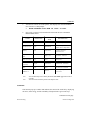
VPG displays the current unit system and prompts:
>
SELECT UNIT SYSTEM FOR OUTGOING DATA
1 - MM, TON, SEC, N
2 - MM, G, MSEC, N
3 - MM, KG, MSEC, KN
4 - M, KG, SEC, N
5 - ORIGINAL UNIT
4.
VPG prompts:
>
OUTPUT ONLY ACTIVE PARTS? (Y/N)
•
YES will only output the elements displayed on the screen.
•
NO will output all elements existing in the database.
Continued on next page.
Section 4.1 Page 48
File Manager
WRITE F-CRASH FILE
5.
VPG prompts:
>
ENTER TITLE
6.
After entering the title, VPG displays the CONTROL TERMINATION CARD if a
termination time has not been specified yet. Once the card is defined and the user
selects OK the DYNA deck is written.
note:
If the properties/materials are not assigned to the parts in the database, VPG prompts the
user to define the properties/materials by default, by global default, or by part.
WRITE F-CRASH FILE
This function allows the user to output a F-CRASH (.fcr) data deck directly from the VPG
database.
1.
VPG prompts:
>
ENTER FILE NAME OR “STOP” TO EXIT
•
Enter a file name (up to 24 characters).
2.
If the file name already exists, the program will prompt the following message:
>
FILENAME ALREADY EXISTS, O.K. TO OVERWRITE? (Y/N)
•
YES will overwrite the existing file.
•
NO will prompt for a file name.
3.
VPG prompts:
>
ENTER TITLE
4.
Parameter windows appear and VPG prompts:
>
DEFINE/MODIFY DATA
>
SELECT AN ITEM TO EDIT
Continued on next page.
File Manager
Section 4.1 Page 49
WRITE GENESIS FILE
WRITE LINE DATA FILE
5.
VPG prompts:
>
OUTPUT ONLY ACTIVE PARTS? (Y/N)
?
YES
•
Outputs parts currently turned on.
NO
•
Outputs entire database.
note:
If the properties/materials are not assigned to the parts in the database, VPG prompts the
user to define the properties/materials by default, by global default, or by part. Supported
properties are listed in Appendix D, VPG Capabilities for F.E.A. Programs.
WRITE GENESIS FILE
This function allows the user to output a GENESIS (.dat) data deck directly from the VPG
database.
WRITE LINE DATA FILE
This function allows the user to output a LINE/SURFACE DATA (.lin) data file directly
from the VPG database.
1.
VPG prompts:
>
ENTER FILE NAME OR "STOP" TO EXIT
•
Enter a file name (up to 24 characters). The .lin extension is suggested.
2.
If the file name already exists, the program will prompt the following message:
>
FILENAME ALREADY EXISTS, O.K. TO OVERWRITE? (Y/N)
?
YES
NO
•
YES will overwrite the existing file.
•
NO will prompt for a file name.
Continued on next page.
Section 4.1 Page 50
File Manager
WRITE MOLDFLOW FILE
3.
VPG prompts:
>
WRITE LINES/SURFACES ONLY IN ACTIVE PARTS? (Y/N)
?
YES
NO
•
YES will only output the lines/surfaces displayed on the screen.
•
NO will output all elements lines/surfaces in the database.
WRITE MOLDFLOW FILE
This function allows the user to output the current model data into an external file in
MOLDFLOW format.
note:
Node and element numbers must be in sequence to write a MOLDFLOW file. The user
may either renumber or compress nodes/elements (see NODE OPTIONS menu). If the
nodes are not in sequential order, VPG prompts:
>
>
RENUMBER NODE NUMBERS AND TRY AGAIN (or)
RENUMBER ELEMENT NUMBERS AND TRY AGAIN
1.
VPG prompts:
>
ENTER ROOT NAME FOR INPUT FILES OR STOP TO EXIT
•
VPG writes three files in accordance with the MOLDFLOW format (.mfl,
.nod, and .tri).
2.
If the file name already exists, the program will prompt the following message:
>
FILENAME ALREADY EXISTS, O.K. TO OVERWRITE? (Y/N)
•
YES will overwrite the existing file.
•
NO will prompt for a file name.
3.
After entering file name, VPG prompts:
>
SELECT UNIT CURRENTLY USED IN DATABASE
?
MM
CM
IN
Continued on next page.
File Manager
Section 4.1 Page 51
WRITE NASTRAN
4.
VPG prompts:
>
OUTPUT ONLY ACTIVE PARTS? (Y/N)
•
YES will only output the elements displayed on the screen.
•
NO will output all elements existing in the database.
5.
VPG prompts:
>
ENTER TITLE
WRITE NASTRAN
This function allows the user to output the current model data to an external file into
NASTRAN format. The user may output either the complete model data or partial model
data.
1.
VPG prompts:
>
ENTER CONTROLS OPTION
ANALYSIS TYPE
•
Displays a submenu with selective analysis types:
STATICS
NORMAL MODES
BUCKLING
FREQUENCY RESPONSE
TRANSIENT RESPONSE
FORMAT OPTION
•
Displays a submenu with file format options:
SINGLE FIELD (fixed format columns of eight)
DOUBLE FIELD (double precision)
FREE FORMAT
OUTPUT OPTION
•
Displays a submenu with ouput options:
PRINT
PUNCH
ALL
Continued on next page.
Section 4.1 Page 52
File Manager
PARAM CARDS
•
Displays the parameter modify window (see figure below).
WRITE FILE
EXIT
2.
VPG prompts:
>
ENTER FILE NAME OR "STOP" TO EXIT
•
Enter a file name (up to 24 characters).
3.
VPG prompts:
>
OUTPUT ONLY ACTIVE PARTS? (Y/N)
?
YES
NO
•
YES will only output the elements displayed on the screen.
•
NO will output all elements existing in the database.
4.
VPG prompts:
>
ENTER ANALYSIS TITLE
•
Any alphanumeric input up to 72 characters may be entered as the title of the
NASTRAN bulk data file.
File Manager
Section 4.1 Page 53
WRITE PAMCRASH FILE
WRITE PAMCRASH FILE
This function allows the user to output a PAMCRASH (.pc) data file directly from the VPG
database.
1.
2.
VPG prompts:
>
ENTER FILE NAME OR “STOP” TO EXIT
•
Enter a file name (up to 24 characters).
If the file name already exists, the program will prompt the following message:
>
FILENAME ALREADY EXISTS, O.K. TO OVERWRITE? (Y/N)
•
YES will overwrite the existing file.
•
NO will prompt for a file name.
3.
VPG prompts:
>
SELECT PAMCRASH VERSION:
?
1 - SEQUENTIAL
2 - FREE NUMBERING
>
DO YOU WANT TO USE KEYWORD INPUT(Y/N)
?
YES
NO
4.
VPG prompts:
>
OUTPUT ONLY ACTIVE PARTS? (Y/N)
?
YES
NO
5.
VPG prompts for optional keyword cards via pop ups.
6.
VPG prompts:
>
ENTER TITLE
•
The user enters an alpha-numeric title containing a maximum of 48 characters.
•
VPG returns the user to the FILE MANAGER menu.
note:
Section 4.1 Page 54
If the properties/materials are not assigned to the parts in the database, VPG prompts the
user to define the properties/materials by default, by global default, or by part. Supported
properties are listed in Appendix D, VPG Capabilities for F.E.A. Programs.
File Manager
WRITE RADIOSS FILE
WRITE RADIOSS FILE
This function allows the user to output a RADIOSS (.rad) data file directly from the VPG
database. When writing a RADIOSS input file, VPG creates default materials and element
properties for some elements. For specific translation properties, see the RADIOSS conversion tables, Appendix D, H.
1.
VPG prompts:
>
ENTER FILE NAME OR “STOP” TO EXIT
•
Enter a file name (up to 24 characters).
2.
If the file name already exists, the program will prompt the following message:
>
FILENAME ALREADY EXISTS, O.K. TO OVERWRITE? (Y/N)
•
YES will overwrite the existing file.
•
NO will prompt for a file name.
3.
VPG prompts:
>
SELECT RADIOSS VERSION
?
1 - VERSION 2.2
2 - VERSION 2.3
4.
VPG prompts:
>
ENTER TITLE
•
The user enters an alpha-numeric title containing a maximum of 48 characters.
•
VPG returns the user to the FILE MANAGER menu.
5.
VPG prompts:
>
OUTPUT ONLY ACTIVE PARTS? (Y/N)
•
YES outputs only the elements displayed on the screen.
•
NO outputs all of the existing elements in the database.
•
After entering the appropriate selection, the user returns to the FILE MANAGER menu.
note:
File Manager
If the properties/materials are not assigned to the parts in the database, VPG prompts the
user to define the properties/materials by default, by global default, or by part. Supported
properties are listed in Appendix D, VPG Capabilities for F.E.A. Programs.
Section 4.1 Page 55
SUMMARY REPORT
SUMMARY REPORT
This function allows the user to output a model summary with the following information:
1.
2
3.
the break down of node ranges by part
the break down of element ranges by part
the break down of part connectivity (part to part connections) by part.
The file is written in the working directory as an ASCII file.
Section 4.1 Page 56
File Manager
PRE PROCESSOR
The Pre Processor menu contains a series of submenus with the ability to create and edit
lines, surfaces, elements, material properties and element properties.
PRE PROCESSOR
LINE
SURFACE
ELEMENT
NODE
MODEL CHECKER
SET MENU
BOUNDARY CONDITION
CONSTRAINT
MATERIAL
ELEMENT PROPERTY
CONTACT INTERFACE
DYNA MISC
SUPER ELEMENT
EXIT
The Pre Processor submenus are described in their own individual sections which follow.
note:
DYNA MISC only appears when the analysis code is set to LS-DYNA. SUPER
ELEMENT only appears when the analysis code is set to NASTRAN.
Section 6 Page 58
Pre Processor
LINE
The functions of the LINE MENU are intended to create a new set of line data or modify
existing line data. VPG currently has a limitation of 150,000 lines or 200,000 points
per database. The following options are available in the LINE MENU:
LINE
ADD POINTS
GENERATE ARCS
ARC TANGENT 2 LINES
3 POINT ARC
COPY
COMBINE LINES
SPLINE CURVE
DELETE
EXTEND LINE
GENERATE LINES
IDENTIFY
MIRROR
OFFSET
PROJECT
RESPACE LINE
REVERSE DIRECTION
SCALE LINES
SECTION LINE
SHOW
SPLIT
TRANSFORM
VIEW
EXIT
A detailed description of each function is given in the following sections.
ADD POINTS
ADD POINTS
This function allows the user to add points to an existing line either randomly or between
two selected points.
VPG prompts:
>
SELECT LINE FOR ADDED POINTS
2.
VPG prompts:
>
SELECT POINT LOCATION ON LINE
•
The user may create new points by placing the cursor anywhere on the line
and pressing the left mouse button; or the user may select one the following
options:
BETWEEN 2 POINTS
•
This option allows the user to select 2 end points of a line
segment and
create a specified number of new points between the them (see
step 4).
CURSOR LOCATION
POINT
REJECT LAST
LINE
1.
3.
VPG prompts:
>
BETWEEN 2 POINTS
>
SELECT POINT 1 ON LINE
>
SELECT POINT 2 ON LINE
>
ENTER NUMBER OF POINTS TO BE ADDED
•
The user enters the desired number of points.
4.
EXIT or DONE returns the user to the LINE menu.
Circles indicate the locations where points
have been added.
Continued on next page.
Section 6.1 Page 60
Line
GENERATE ARCS
GENERATE ARCS
This function allows the user to generate arcs and circles either globally, locally or about
a selected node or point. The created arc will be included in the CURRENT PART (see
PART CONTROL MENU).
1.
VPG prompts:
>
CREATE LOCAL COORDINATES
>
PICK NODE/PT FOR ORIGIN
•
VPG is asking for a desired coordinate system (local or global) about which
to create the arc. VPG prompts the user to create a local system. A thorough
explanation of how to create a local coordinate system is covered in the Local
Coordinate System, Section 2.14.
note: Arcs and circles are generated about the local W-axis or global Z-axis.
2.
Once the desired coordinate system is acquired, it will be displayed on the screen
and the prompt will read:
>
ACCEPT? (Y/N/A)
3.
If accepted, VPG prompts:
>
ENTER RAD, TH1, TH2, INC
•
RAD = radius of arc.
•
TH1 = beginning point of arc or circle.
•
TH2 = ending point of arc or circle.
•
INC = angle increment between points (default is 5 degrees).
•
Any real value greater than zero is valid. i.e., 100,0,360,10 is a circle with a
radius of 100 units with an increment of 10 degrees between points.
An arc and a circle have been
generated with the same center.
4.
Line
VPG prompts:
>
SAME CENTER AND PLANE? (YES/NO/EXIT)
•
Do you want to create another circle/arc using the same center and plane?
•
YES returns the user to step 3.
NO returns the user to step 1.
EXIT exits the function.
Section 6.1 Page 61
ARC TANGENT 2 LINES
3 POINT ARC
ARC TANGENT 2 LINES
This command allows the user to create an arc tangent to 2 lines. The arc will be
included in the CURRENT PART (see PART CONTROL MENU). The two intersecting lines will be trimmed by the tangent arc.
VPG prompts for a line:
>
SELECT LINE 1
2.
VPG prompts for a second line:
>
SELECT INTERSECTING LINE
LINE
1.
Arc tangent to two lines.
3.
VPG prompts:
>
ENTER RADIUS OF ARC OR -1 TO EXIT
•
Any real value greater than zero is valid.
•
An arc tangent to the 2 lines is drawn. The lines need to be long enough to
make actual contact with the arc but do not need to intersect.
3 POINT ARC
This function allows the user to create an arc through 3 points/nodes that are not colinear. The created arc will be included in the current part.
1.
2.
VPG prompts:
>
PICK NEXT POINT OR NODE
•
This command will be prompted 3 times.
•
When 3 points or nodes are selected an arc will automatically be drawn.
EXIT will terminate this function.
Continued on next page.
Section 6.1 Page 62
Line
COPY
The circles represent the points through
which the arc is drawn.
point 3
point 2
point 1
COPY
This function allows the user to generate a set of duplicate lines. The user may then
simultaneously translate and/or rotate the copied lines.
1.
VPG prompts:
>
PICK LINE TO COPY
>
SELECT LINES
•
Select DONE once desired lines have been selected.
2.
VPG prompts:
>
CREATE LOCAL COORDINATES
>
PICK NODE/PT FOR ORIGIN
•
VPG is asking for a desired coordinate system (local or global). VPG prompts the
user to create a local system. A thorough explanation of how to create a local coordinate system is covered in Local Coordinate System, Section 3.5.
•
Once the desired coordinate system is acquired, it will be displayed on the screen.
3.
VPG prompts:
>
ACCEPT? (Y/N/A)
?
YES
•
If YES, then go to step 4.
Continued on next page.
Line
Section 6.1 Page 63
COMBINE LINES
NO
•
ABORT
•
If NO, then go to step 2.
If ABORT, then function is terminated.
VPG prompts:
>
ENTER NUMBER OF COPIES (positive integer)
5.
VPG prompts:
>
MOVE OR ROTATE (M/R)
?
MOVE
ROTATE
ABORT
•
If MOVE is entered,
>
ENTER U, V, W INCREMENTS
•
i.e., 0,0,1000 will copy the selected line(s) 1000 units along the
W-axis.
>
INCLUDE COPIED LINE IN ITS ORIGINAL PART (Y/
N)
•
Allows the user to specify the desired part.
•
If ROTATE is entered,
>
ENTER ANGLE INCREMENT (degrees)
•
i.e., 200 degrees.
>
INCLUDE COPIED LINE IN ITS ORIGINAL PART (Y/
N)
•
Allows the user to specify the desired part.
•
If ABORT is entered, then the function is terminated.
LINE
4.
COMBINE LINES
This function allows the user to combine multiple lines into a new single line with a new
line number. The original lines will be deleted after they are combined. The combined
line should be selected in a logical sequence to form the new line.
1.
VPG prompts:
>
PICK LINES TO COMBINE
2.
Once all the lines are selected, DONE or EXIT combines the lines and exits the
command.
Section 6.1 Page 64
Line
SPLINE CURVE
SPLINE CURVE
This function allows the user to draw a spline curve line through multiple points or nodes
or any combination of points or nodes. A minimum of 3 points or nodes are required.
1.
VPG prompts:
>
PICK NEXT POINT OR NODE
?
ABORT
DONE
EXIT
KEY IN XYZ
•
The user may enter up to 3 points globally to define a point or node.
INCREMENTAL XYZ
•
The user may enter DX, DY, DZ from the previous point selected to define
a point or node.
NODE
POINT
REJECT LAST
2.
DONE and EXIT will exit the function.
An example of a generated spline curve.
Line
Section 6.1 Page 65
DELETE
EXTEND LINE
GENERATE LINES
DELETE
This function allows the user to delete selected lines.
EXTEND LINE
This function allows the user to extend a line by a specified distance along the axis of
the line at either end of the line.
LINE
1.
VPG prompts:
>
SELECT LINE TO EXTEND
2.
VPG prompts:
>
SELECT END POINT TO EXTEND LINE
•
Select the desired end point of the line to extend.
3.
VPG prompts:
>
ENTER LENGTH TO BE EXTENDED
•
Input any real number.
4.
Selecting UNDO will undo the last extend operation.
GENERATE LINES
This function allows the user to draw a line between nodes or points via a combination
of keyboard and mouse selections. The created lines are incorporated into the CURRENT PART (or see PART CONTROL MENU).
1.
VPG prompts:
>
PICK NEXT POINT OR NODE
INCREMENTAL XYZ
•
The user may enter an additional DX, DY, DZ from the previous point or
node selected to continue drawing the line.
NODE
POINT
REJECT LAST
Continued on next page.
Section 6.1 Page 66
Line
IDENTIFY
•
•
DONE completes the creation of the line and starts the generation of a new
line.
EXIT will terminate this function.
IDENTIFY
This function allows the user to identify any node or point and its corresponding global
location in X, Y, Z coordinates.
1.
VPG prompts:
>
PICK NODES/POINTS
?
ALL NODES
EXIT
KEY IN NODE #
NODE
POINT
•
If ALL NODES is selected, the numbers of the displayed nodes will
appear on screen at their node locations (the first clear button in the DISPLAY PARAMETER OPTIONS WINDOW will remove the numbers )
•
If NODE is selected, the number of the node nearest the cursor location will
appear on screen. The following message will echo on the command line:
> NODE xxxx X= x.xxx Y= y.yyy Z= z.zzz
•
If POINT is selected, the number of the point nearest the cursor location will
appear on screen. The following message will echo on the command line:
> POINT xxxx X= x.xxx Y= y.yyy
Z= z.zzz
•
EXIT will send the user to the LINE menu.
932
763
890
Line
Section 6.1 Page 67
MIRROR
MIRROR
This function allows the user to reflect a copy of desired lines across a local or global
coordinate plane.
LINE
1.
VPG prompts:
>
CREATE LOCAL COORDINATES
>
PICK NODE/PT FOR ORIGIN
•
VPG is now asking for a coordinate system to mirror the lines. VPG prompts
the user to create a local system. A thorough explanation of how to create a
local coordinate system is covered in Local Coordinate System, Section 3.5.
2.
Once the desired coordinate system is acquired, it will be displayed on the
screen and the prompt will read:
>
ACCEPT? (Y/N/A)
3.
If the user selects YES, then VPG prompts:
>
PICK LINES TO MIRROR
>
SELECT LINES
>
PICK A LINE(L), ELEM(C),
>
OR PART NAME(P) OF A PART.
•
The user must now select a target part with which to mirror lines.
4.
Once desired lines have been selected, DONE or EXIT takes the user to the next
step.
5.
VPG prompts:
>
ENTER PLANE OF MIRROR (XY, YZ, XZ)
•
The user may now select a local plane of symmetry in which to mirror lines.
6.
VPG prompts:
>
MIRROR LINES TO ORIGINAL PART? (Y/N)
?
YES
NO
•
YES will place all selected lines into the ORIGINAL PART.
•
NO will place all selected lines into the current part.
Section 6.1 Page 68
Line
OFFSET
OFFSET
This function allows the user to copy and offset a selected line. The new line is generated in the u-v plane according to a user-specified distance and direction.
1.
VPG prompts:
>
SELECT LINE TO OFFSET
2.
Once the desired lines have been selected, VPG prompts:
>
DEFINE PLANE FOR LINE OFFSET
>
PICK NODE/PT FOR ORIGIN
•
The user enters a coordinate system to define the plane in which the line lies.
If the line does not lie in the global XY, XZ, or YZ plane, then the user
selects three points on the line to define the plane. A thorough explanation
of how to create a local coordinate system is covered in Local Coordinate
System, Section 3.5.
3.
Once the desired coordinate system is acquired, it will be displayed on the
screen and the prompt will read:
>
ACCEPT? (YES/NO)
4.
If the user selects YES, then VPG prompts:
>
ENTER OFFSET DISTANCE IN U-V PLANE OR -1 TO EXIT
•
The user enters a positive distance and an arrow appears at the beginning of
the line.
5.
VPG prompts:
>
ACCEPT OFFSET DIRECTION? (YES/NO)
•
YES creates a line in the displayed direction at the specified distance.
•
NO creates a line opposite the displayed direction at the specified distance.
w
u
v
Offset direction
z
y
x
Line
Section 6.1 Page 69
PROJECT
RESPACE LINE
PROJECT
This function projects lines and/or points onto selected surfaces.
VPG prompts:
>
SELECT SURFACES
2.
Once the desired surfaces are selected, click on DONE. VPG prompts the user
to create/choose a coordinate system.:
>
DEFINE PROJECTION VECTOR
>
PICK NODE/PT FOR ORIGIN
LINE
1.
3.
After accepting the coordinate system, VPG prompts:
>
SELECT ENTITY FOR PROJECTION:
4.
Based on the selected entity, lines/points are projected onto the surface. If the
point or points on the line do not intersect the surface along the global Z or W
vector, VPG displays a message:
>
NO PROJECTION FOUND FOR XXXX POINT.
RESPACE LINE
This function allows the user to respace the number of points on the selected line equidistantly.
1.
VPG prompts:
>
SELECT LINE FOR RESPACING POINTS
2.
Once the desired line is selected, VPG prompts:
>
ENTER NUMBER OF POINTS ON LINE OR E TO EXIT
•
Enter any integer greater than two. VPG includes the end points of the line
as part of the total count of points on the line.
3.
EXIT or DONE to exit this function.
Section 6.1 Page 70
Line
REVERSE DIRECTION
SCALE LINES
REVERSE DIRECTION
Each line has a direction defined from the starting point to the end point of the line. This
function allows the user to reverse the line direction. Arrowheads on the line (presented
during SHOW LINE, SPLIT, etc.) are identifiable points and also indicate the line direction.
1.
VPG prompts:
>
SELECT LINES
•
Once the line is selected the direction is automatically reversed.
SCALE LINES
This function allows the user to scale the selected lines or points with respect to any axis
(global or local) using magnification factors in the X, Y, or Z (U, V, or W) directions. A
scale factor greater than 1 will magnify the line, whereas a scale factor less than 1 will
reduce the line.
1.
VPG prompts:
>
PICK LINES TO SCALE
>
SELECT LINES
>
PICK A LINE(L), ELEM(C),
>
OR PART NAME(P) OF A PART
•
The user must now select a target part with which to scale lines.
•
Select DONE once the desired lines have been selected.
2.
VPG prompts:
>
CREATE LOCAL COORDINATES
>
PICK NODE/PT FOR ORIGIN
•
VPG asks for a coordinate system to scale the lines and prompts the user to
create a local system. A thorough explanation of how to create a local coordinate system is covered in Local Coordinate System, Section 3.5.
3.
Once the desired coordinate system is created, it will be displayed on the screen
and the user will be prompted to accept or decline the system. If the user
accepts, then VPG prompts:
Continued on next page.
Line
Section 6.1 Page 71
SECTION CUT
>
•
note:
ENTER X, Y, Z SCALE FACTORS
The user selects the desired scale factor.
The factors 1,-1,1 reflect the line size in the negative Y-direction (across the UV plane); the factors
0.5,0.5,0.5 reduce the lines by 0.5.
SECTION CUT
LINE
This function will generate line segments along a user defined UV plane at the intersection of selected lines intersecting the UV plane. The line section that is created will be
included in the CURRENT PART (see PART CONTROL MENU).
1.
VPG prompts:
>
CREATE LOCAL COORDINATES
>
PICK NODE/PT FOR ORIGIN
•
VPG is now asking for a coordinate system to create section lines. VPG
prompts the user to create a local system. A thorough explanation of how to
create a local coordinate system is covered in Local Coordinate System, Section 3.5.
2.
Once the desired coordinate system is acquired, it will be displayed on the
screen.
3.
If the user accepts the coordinate system, VPG prompts:
>
DISTANCE FROM PLANE, W=?
•
Users may now input a distance along the W-axis from origin of the selected
coordinate system.
•
Any real value is a valid response.
•
The section line will be created at the distance W in the UV plane.
Section 6.1 Page 72
Line
SHOW LINES
A section line is defined at a specific
distance from the user defined local
coordinate system.
4.
VPG prompts:
>
SELECT LINES
•
ABORT exits the function without creating a section line.
DONE will complete the section line and return the user to step 4.
EXIT completes the section line and exits this function.
SHOW LINES
The user may identify any existing line or line direction using this function. The selected line is highlighted (the starting point is labeled with a circle) and subsequent
points are represented with arrowheads oriented in the direction of the line.
The arrows indicate point
locations on the line and line
direction.
Line
Section 6.1 Page 73
SPLIT
TRANSFORM
SPLIT (LINE)
The user may split a line at a desired cursor location, at the nearest point, or at an
intersection with another line.
VPG prompts:
>
PICK LINE TO SPLIT
2.
VPG prompts:
>
PICK SPLIT LOCATION
?
ABORT
CURSOR LOCATION (anywhere the user clicks the mouse)
LINE
(the line will split at the location closest to the intersection of the
selected line)
POINT
(the line will split at the selected point closest to the selected line)
REJECT LAST
•
ABORT will exit this function.
LINE
1.
TRANSFORM
This function allows the user to translate or rotate the selected lines or points to a new
location.
1.
VPG prompts:
>
CREATE LOCAL COORDINATES
>
PICK NODE/PT FOR ORIGIN
•
VPG is asking for a desired coordinate system (local or global). VPG prompts
the user to create a local system. A thorough explanation of how to create a
local coordinate system is covered in Local Coordinate System, Section 3.5.
2.
Once the coordinate system is determined, VPG prompts:
?
MOVE
ROTATE
Continued on next page.
Section 6.1 Page 74
Line
•
>
•
•
ABORT
If MOVE is entered:
ENTER U, V, W INCREMENTS
i.e., 0,0,1000. This will move the selected line(s) 1000 units along the W-axis.
If ROTATE is selected, the user enters an angle increment. Note: all rotational
commands are about the local W-axis or the global Z-axis.
4.
VPG prompts:
>
SELECT ENTITY FOR TRANSFORM
?
POINT
LINE
ABORT
5.
If the user selects the point option to transform, the following options
are available:
?
AGAIN
•
Repeats the previous transformation.
DONE
EXIT
LINE
REVERSE OPERATION
•
Reverses the previous transformations.
6.
If the user selects a line option to transform, VPG prompts the user to select a
line or point.
7.
After selecting the line/point, done executes the transformation.
e.
Line
Section 6.1 Page 75
LINE
Section 6.1 Page 76
Line
SURFACE OPTIONS
Commands in this menu are used to create and modify cad surface data in VPG. VPG
imports surface data and line data and converts it into VPG format with a bulletin. The IGES
translator supports most IGES entities. Supported IGES entities are listed on page the following page.
SURFACE OPTIONS
BOUNDARY LINE
COPY
CREATE S-LINES
DELETE
2 LINE SURFACE
3 LINE SURFACE
4 LINE SURFACE
MIRROR
REVERSE NORMAL
RESPACE U-V LINE
SURFACE INTERSECT
U-V LINE ON/OFF
SCALE
SURF NORMAL ON/OFF
SPLIT
SECTION REVOLUTION
SHOW
SWEEP SURFACE
TRANSFORM
TRIM SURFACE
VIEW
EXIT
A detailed description of each function is given in the following sections.
note:
The following are working definitions used throughout this section of VPG:
!
!
!
Domain—The trimmed surface of the common region of the interior of the outer
boundary and the exterior of the inner boundaries as well as the boundary curves.
Outer Boundary—One boundary that is situated within the domain (the surface
that is to be trimmed). In particular, it describes the boundary curve of the
domain.
Inner Boundary—Any number of inner boundaries including zero. The set of
inner boundaries satisfies two criteria:
(a) The curves as well as their interiors are mutually disjointed.
(b) Each curve lies in the interior of the outer boundary.
SUPPORTED IGES ENTITY TYPES
VPG supports the following IGES entity types.
ENTITY NAME
TYPE
ENTITY NAME
TYPE
_________________________________________________________________________
Null
0
Tabulated Cylinder Entity
122
Circular Arc
100
Transformation Matrix
124
Composite Curve
102
Rational B-Spline Curve
126
Conic Arc
104
Rational B-Spline Surface
128
Copious Data
106
Offset Surface
140
Plane
108
Boundary
141
Line
110
Curve on a Parametric Surface
142
Parametric Spline Curve
112
Bounded Surface
143
Parametric Spline Surface
114
Trimmed (Parametric) Surface
144
Point
116
Subfigure Definition
308
Ruled Surface
118
Singular Subfigure Instance
408
Surface of Revolution
120
________________________________________________________________________
Section 6.2 Page 78
Surface Options
BOUNDARY LINE
COPY
BOUNDARY LINE
This function creates a line on the boundary of a selected surface.
1.
VPG prompts the user to select a surface on the screen.
>
SELECT SURFACE FOR BOUNDARY LINE
2.
VPG creates a boundary line around the selected surface and includes it in the
current part.
note:
The boundary line should be split if it is intended for use with line meshing.
COPY
This function copies selected surface(s) to a new location.
1.
VPG prompts the user to select surfaces to copy.
2.
VPG prompts the user to create a local coordinate system. The user also has the
option to select the global coordinate system. (Refer to Local Coordinate
System, Section 3.5 for a thorough explanation of this procedure.)
3.
Once the desired coordinate system has been defined, VPG prompts for the
number of copies.
4.
Once the number of copies has been entered, VPG prompts for the method of
copy.
>
MOVE OR ROTATE (M/R)
?
MOVE
>
ENTER U, V, W INCREMENTS
!
i.e., /0,0,1000/. This copies the surface(s) 1000 units along the
W-axis or global Z.
ROTATE
!
If ROTATE is selected, enter the angle increment (right-hand
rule) about
the W-axis. The remaining commands are the same as the
MOVE option.
ABORT
Continued on next page.
Surface Options
Section 6.2 Page 79
CREATE S-LINES
DELETE SURFACES
2 LINE SURFACE
3 LINE SURFACE
5.
VPG prompts:
>
INCLUDE COPIED SURFACE IN ITS ORIGINAL PART? (Y/N)
?
YES
NO
CREATE S-LINES
This function creates sectional line data on the selected surface.
1.
VPG prompts the user to select a surface on the screen.
2.
Once the surface is selected, VPG places edge numbers on the surface and
prompts the user to enter a number of section lines along edges 1 and 2.
3.
VPG creates a set of section lines along edges 1 and 2. These lines are included
in the current part.
DELETE SURFACES
This function deletes the selected surfaces from the database.
2 LINE SURFACE
This function creates a surface from two selected lines. The operation is similar to 2
LINE MESH for elements.
3 LINE SURFACE
This function creates a surface from three selected lines. The procedure is similar to 3
LINE MESH for elements.
note:
note:
Section 6.2 Page 80
Select lines in a clockwise or counterclockwise direction.
The direction of the surface normal dictates the direction of the plate element normals.
Surface Options
)
4 LINE SURFACE
MIRROR
REVERSE NORMAL
RESPACE UV LINES
4 LINE SURFACE
This function creates a surface from four selected lines. The procedure is similar to 4
LINE MESH for elements.
note:
note:
Select lines in a clockwise or counterclockwise direction.
The direction of the surface normal dictates the direction of the plate element normals.
MIRROR
Reflects a copy of desired surfaces across a local or global coordinate plane.
1.
FEMB prompts the user to select a surface on the screen.
2.
FEMB prompts the user to seelct a coordinate system followed by the plane of the
mirror.
3.
The user then has the option of putting the surface in a new part.
REVERSE NORMAL
This function reverses the normal direction of the surface. The surface
normal affects light source shading
on some workstations. REVERSE
NORMAL also controls the normal
direction of the plate elements during meshing.
RESPACE UV LINES
This function changes the UV line density of the selected surfaces.
1.
VPG prompts the user to select a surface on the screen.
2.
VPG labels the edge numbers on the surface and prompts the user to enter the
number of UV lines along edges 1 and 2.
Continued on next page.
Surface Options
Section 6.2 Page 81
SURFACE INTERSECT
UV LINE ON/OFF
3.
note:
VPG creates a set of UV lines along edges 1 and 2. These UV lines are included in
the current part.
This operation changes only the appearance of the selected surfaces. It does not change
the integrity of the surface.
SURFACE INTERSECT
This function creates a line at the intersection between two selected surfaces.
1.
VPG prompts the user to choose a surface.
>
SELECT THE FIRST SURFACE
2.
After selecting the first surface, VPG prompts the user for the second surface.
>
SELECT THE SECOND SURFACE
3.
After selecting the second surface, VPG automatically creates a line at the intersection of the two surfaces. The newly created line is included in the current
part.
UV LINE ON/OFF (toggle)
This function controls the on and off display of UV lines on a surface.
note:
Section 6.2 Page 82
Toggling the UV lines off has no effect on the outcome of meshing , trimming or splitting of
surfaces.
Surface Options
SCALE
SURF NORMAL ON/OFF
SCALE
This function allows the user to scale selected surfaces with respect to any axis (global or
local) using magnification factors in the X, Y, or Z (U, V, or W) directions. A scale
factor greater than 1 will magnify the surface, whereas a scale factor less than 1 will
reduce the surface.
1.
VPG prompts the user to select the surfaces.
2.
Once the surfaces have been selected, VPG prompts the user to create a local
coordinate system. The user also has the option to select the global coordinate
system. (Refer to Local Coordinate System, Section 3.5 for a thorough explanation of this procedure.)
3.
Once the desired coordinate system has been defined, VPG prompts:
>
ENTER X,Y,Z SCALE FACTORS
!
This scales the surface.
SURF NORMAL ON/OFF (toggle)
This function controls the on and off display of normal vectors on a surface. The normal
vector below is shown at the center of the surface.
Surface Options
Section 6.2 Page 83
SPLIT
SPLIT
This function allows the user to split selected surfaces in several different ways. All the
options for splitting surfaces are addressed below.
1.
VPG prompts for a surface.
2.
Upon selection of the surface, VPG prompts :
>
SELECT OPTION TO SPLIT (DEFAULT IS SECTION LINE)
!
User selects a displayed section line to split a surface.
?
LINEAR SEGMENTS
>
SELECT NEXT POINT FOR LINEAR SEGMENT
!
The user may pick up to 500 locations on the surface to complete
a piecewise linear curve.
RESPACE U-V LINES
>
ENTER THE NUMBERS OF UV LINES: N1, N2
!
N1 or N2 cannot be greater than 199.
!
The user may choose a desired section line, once the user selects
the section lines for N1, N2 .
SPLINE CURVE
>
SELECT NEXT POINT FOR SPLINE CURVE
!
The user may pick up to 500 locations on the surface in order to
complete a spline curve.
SURFACE INTERSECTION
>
SELECT THE SECOND SURFACE
!
Once the user selects the second surface, the first surface splits at
the intersection of the two surfaces. The user may split the
second surface at the same intersection.
U-V LINES
>
SELECT UV LINE TO SPLIT SURFACE
TWO POINTS ON BOUNDARY
>
SELECT FIRST POINT ON BOUNDARY
>
SELECT SECOND POINT ON BOUNDARY
!
VPG splits the surface once the user selects the second boundary
point.
EXIT
Section 6.2 Page 84
Surface Options
SECTION REVOLUTION
SHOW
SECTION REVOLUTION
This function creates a surface by rotating a selected section line (the generatrix) up to
360º about a vector (the axis of revolution).
1.
VPG prompts:
>
SELECT THE AXIS OF REVOLUTION
>
SELECT THE FIRST POINT
?
ABORT
LINE (TWO POINTS)
!
The user may select a line, defined by only two points, to be the
axis of revolution.
TWO POINTS
!
Default.
REJECT LAST POINT
UNDO
!
>
!
>
?
2.
The user has been prompted to select the first of two points required to define
the
axis of revolution. Once the first point has been selected, VPG prompts:
SELECT THE SECOND POINT FOR THE AXIS
The user selects the second point, then VPG displays a vector representing
the axis of revolution.
SELECT A LINE AS THE GENERATRIX OF REVOLUTION
LINE (default)
LINE SEGMENT (allows user to combine line segments into one line)
DONE
REJECT (rejects last selection)
VPG prompts:
>
ENTER START AND END ANGLE [DEFAULT: 0., 360.]
!
The user may enter a desired start angle and end angle to generate a surface or
press ENTER to generate a 360 degree angle.
SHOW
This function highlights the selected surface and UV lines in white color. Choosing
CLEAR in the VPG DISPLAY PARAMETER OPTIONS MODULE removes highlights.
Surface Options
Section 6.2 Page 85
SWEEP SURFACE
SWEEP SURFACE
This function allows the user to create a surface via the selection of a section line and a
direction line. The surface is generated along the length of the direction line.
direction
direction
pattern
pattern
1.
VPG prompts the user to select a sweep type:
>
SELECT SWEEP TYPE
NORMAL SWEEP
!
The section lines remain perpendicular to the line of direction.
RIGID SWEEP
!
The section lines remain parallel to the line of pattern.
2.
VPG prompts the user to select a surface.
>
SELECT A LINE FOR THE SWEEP PATTERN
!
The selected line will act as a constant cross section for the new surface.
3.
Once the line has been selected, VPG prompts:
>
SELECT A LINE FOR THE SWEEP DIRECTION
!
The new surface will generate along the selected line and the user will return
to step 2.
Section 6.2 Page 86
Surface Options
TRANSFORM
TRIM SURFACE
TRANSFORM
This function allows the user to move or rotate a selected surface either locally or globally.
1.
VPG prompts:
>
CREATE LOCAL COORDINATES
>
PICK NODE/PT FOR ORIGIN
VPG prompts the user to create a local coordinate system. The user also has the
option to select the global coordinate system. (Refer to Local Coordinate
System, Section 2.14 for a thorough explanation of this procedure.)
2.
Once the desired coordinate system has been defined, VPG prompts:
>
MOVE OR ROTATE (M/R)
?
MOVE
>
ENTER U, V, W INCREMENTS
•
i.e. /0,0,1000/. This will transform the selected surface(s) 1000
units
along the W-axis.
ROTATE
•
If ROTATE is entered, enter angle increment (right hand rule)
about the
W-axis. The remaining commands are the same as the MOVE
option.
ABORT
!
User will now be prompted to select the surface to be transformed.
3.
VPG prompts the user to select surfaces to transform. User also has the option to
select AGAIN or REVERSE to repeat the rotation or movement. Once the
desired surfaces are selected, enter DONE or EXIT to continue.
TRIM SURFACE
This function defines curves for trimming edges and/or cutting holes on the selected
surface. The defined curves may be poly-lines, b-spline lines, circles, piecewise linear
segments, or intersecting lines of two surfaces.
1.
VPG prompts for a surface:
>
SELECT SURFACE FOR TRIM OPERATION
Surface Options
Section 6.2 Page 87
CIRCLE
2.
Upon selection of the surface, VPG prompts:
>
SELECT POINT ON SURFACE FOR TRIM LINE
ABORT
CIRCLE
INTERSECTION LINE
OPEN CURVE
POINT
SPLINE CURVE
REJECT LAST POINT
DONE (CLOSED)
EXIT
This function cuts circles on a selected surface. The user defines the location of the
circle via mouse pick.
-TRIM SURFACE
CIRCLE
1.
VPG prompts:
>
SELECT THE CENTER OF THE CIRCLE
!
The user defines the center of the circle anywhere on the
surface.
>
SELECT A POINT ON THE CIRCLE
!
The user may select a second point on the surface to define the
radius of the circle. VPG proceeds to draw the circle.
2.
The user should then select exit. VPG prompts:
Continued on next page.
Section 6.2 Page 88
Surface Options
INTERSECTION LINE
>
?
SELECT A CLOSED CURVE AS OUTER BOUNDARY
ABORT
DONE
EXIT
SURFACE BOUNDARY
!
Selects the outer, closed, surface boundary.
CURVE ON SURFACE
!
The user may select an existing curve on the surface (open or
closed)
as the outer boundary of the trim operation.
REJECT LAST CURVE
!
Deselects the curve selected for the trim operation.
3.
VPG prompts:
>
SELECT CLOSED CURVE AS INNER BOUNDARY
?
ABORT
DONE
EXIT
NO INNER BOUNDARY
!
VPG trims the surface of the outer boundary.
CURVE ON SURFACE
!
The user may select an existing curve on the surface ( open or
closed )
as the inner boundary of the trim circle operation.
4.
VPG then prompts:
>
DELETE THE ORIGINAL SURFACE? (Y/N)
!
YES generates a trimmed surface.
NO generates a trimmed surface and retains a copy of the original
surface.
5.
The user is returned to step 1 of TRIM SURFACE command.
-TRIM SURFACE
INTERSECTION LINE
This function allows the user to trim away the intersection of two surfaces.
Continued on next page.
Surface Options
Section 6.2 Page 89
1.
VPG prompts:
>
SELECT SURFACE FOR TRIM OPERATION
note:
This surface is referred to as a "primary surface" in this section.
>
SELECT THE SECOND SURFACE
!
Once the user selects the second surface, VPG draws a boundary line between
the two intersecting surfaces.
note:
This surface is referred to as a "secondary surface" in this section.
2.
Once the second surface has been selected and the user enters EXIT, VPG
prompts:
>
SELECT A CLOSED CURVE AS OUTER BOUNDARY
?
ABORT
DONE
EXIT
SURFACE BOUNDARY
!
This creates the outer closed-surface boundary.
CURVE ON SURFACE
!
This locates an existing curve on the surface (open or closed) as
the outer boundary of the trim operation.
REJECT LAST CURVE
!
This rejects the last curve selected for the trim operation.
3.
VPG prompts:
>
SELECT CLOSED CURVE AS INNER BOUNDARY
!
This retains the surface between the outer boundary and the inner boundary
during the trim operation. The inner boundary can be a line segment, open
spline, closed spline, or circle.
?
ABORT
DONE
EXIT
NO INNER BOUNDARY
!
This trims the outside surface of the outer boundary.
CURVE ON SURFACE
!
The user may select an existing curve on the surface (open or
closed ) as the inner boundary of the trim operation.
REJECT LAST CURVE
!
This rejects the last curve selected for the trim operation.
Continued on next page.
Section 6.2 Page 90
Surface Options
OPEN CURVE
POINT
SPLINE CURVE
4.
VPG then prompts:
>
DELETE THE ORIGINAL SURFACE? (Y/N)
!
YES generates a trimmed surface.
NO generates a trimmed surface and retains the original surface.
5.
VPG returns the user to step 2 of the TRIM SURFACE command.
-TRIM SURFACE
OPEN CURVE
This function defines an open curve on a selected surface. After determining, the surface, type of curve, and points, this function connects the points leaving the curve open,
with the first and last point selected as the starting and ending points of the curve.
-TRIM SURFACE
POINT
POINT is the default option in the trim surface menu. Users may pick locations on the
surface defining piecewise linear segments for trim operations .
-TRIM SURFACE
SPLINE CURVE
This function cuts spline curves on a selected surface. The user defines the location of
the spline via mouse pick.
Continued on next page.
Surface Options
Section 6.2 Page 91
1.
VPG prompts:
>
SELECT NEXT POINT FOR SPLINE CURVE.
Ÿ
Once the user has selected the points for the curve, then enters DONE
(CLOSED) or DONE (OPEN) to complete the spline.
!
DONE (CLOSED) defines a closed spline curve passing through
all the points selected.
!
OPEN CURVE defines a spline curve passing through all the
points selected, with the first and last point selected as the
starting and ending
points of the curve. The user then selects exit twice.
2.
VPG prompts:
>
SELECT A CLOSED CURVE AS OUTER BOUNDARY
?
ABORT
DONE
EXIT
SURFACE BOUNDARY
!
Selects the outer closed surface boundary.
CURVE ON SURFACE
!
The user may select an existing curve on the surface (open or
closed) as the outer boundary of the trim operation.
REJECT LAST CURVE
3.
VPG prompts:
>
SELECT CLOSED CURVE AS INNER BOUNDARY
!
The surface between the outer boundary and the inner boundary will be retained during the trim operation. The inner boundary can be a line segment,
open spline, closed spline, or circle.
?
ABORT
DONE
EXIT
NO INNER BOUNDARY
!
The surface outside of the outer boundary will be trimmed.
CURVE ON SURFACE
!
The user may select an existing curve on the surface ( open or
closed ) as the inner boundary of the trim operation.
REJECT LAST CURVE
!
Deselects the curve selected for the trim operation.
Continued on next page.
Section 6.2 Page 92
Surface Options
REJECT LAST POINT
DONE (CLOSED)
4.
VPG then prompts:
>
DELETE THE ORIGINAL SURFACE? (Y/N)
!
YES generates a trimmed surface.
!
NO generates a trimmed surface and retains the original surface.
5.
The user is returned to step 2 of TRIM SURFACE command.
-TRIM SURFACE
REJECT LAST POINT
This function deselects points when defining a trim line.
-TRIM SURFACE
DONE (CLOSED)
This function defines a closed curve on a selected surface. After determining, the surface, type of curve, and points, this function connects the points closing the curve, with
the first and last points selected, linked.
Surface Options
Section 6.2 Page 93
Section 6.2 Page 94
Surface Options
ELEMENT OPTIONS
The ELEMENT OPTIONS menu contains the commands to create and modify elements,
and to instantly mesh IGES surfaces. The 2, 3, and 4 LINE MESH commands create plate
elements via line data selection, and the 6, 8, 9, and 12 LINE SOLID MESH commands
create solid elements via line data selection. Elements can be modified to suit a particular
model with the MODIFY, SPLIT, and COARSE ELEMENT commands.
VPG supports a wide range of element types for LS-DYNA and NASTRAN (refer to Appendix A VPG Capabilities for F.E.A. Programs). The commands in the ELEMENT OPTIONS menu are organized as follows:
ELEMENT OPTIONS
COARSE ELEMENT
CHANGE ID (NASTRAN only)
COPY
CREATE
DELETE
DRAG MESH
ELEMENT TYPE
IDENTIFY ELEMENT
ISO. SHELL FROM PLATE (NASTRAN ONLY)
LABEL
MIRROR
MODIFY
LINE MESH
RENUMBER
REVERSE NORMALS
SPLIT
SURFACE MESH
2 LINE MESH
3 LINE MESH
4 LINE MESH
6 LINE SOLID MESH
8 LINE SOLID MESH
9 LINE SOLID MESH
12 LINE SOLID MESH
TRANSFORM
ATTRIBUTE TABLE ON/OFF (LS-DYNA only)
VIEWING OPTIONS
COARSE ELEMENT
COARSE ELEMENT
This function coarsens 2 CQUAD4 elements or 2 TRIA elements or a combination of a
TRIA and a CQUAD4 into one element.
1.
VPG prompts the user to select 2, 3, or 4 elements:
2.
Once desired elements have been selected:
•
DONE coarsens the selected elements and prompts for more.
•
ABORT or EXIT will exit this function.
The larger elements
were created from
groupings of four
smaller elements.
Section 6.3 Page 96
Element Options
CHANGE ID
COPY
CHANGE ID
This function allows the user to change an existing element number. Parts do not need to
be ON or CURRENT.
1.
VPG prompts the user to select elements:
>
SELECT ELEMENT FOR NEW ELEMENT NUMBER
2.
Once the user selects a desired element, VPG prompts the user to enter the new
element number:
>
ENTER NEW EL. NO. FOR xxxx OR [CR] TO IGNORE
•
Where xxxx is the original element number.
3.
If the user enters a number that already exists, the prompt will read:
>
ELEMENT NUMBER yyyy ALREADY EXISTS, REQUEST DENIED
>
ENTER NEW EL. NO. FOR xxxx OR [CR] TO IGNORE
note:
This function only appears in NASTRAN analysis mode.
COPY
This function allows the user to generate a set of duplicate elements. The user may
simultaneously translate, rotate, or offset (in the normal direction) the copied elements.
1.
VPG prompts the user to select the elements to be copied:
>
SELECT ELEMENTS
2.
Once the desired elements have been selected, DONE or EXIT continues to the
next step where VPG prompts:
>
ENTER NUMBER OF COPIES
3.
Then VPG prompts:
>
ENTER COPY OPTION (M/R/N/MA)
?
MOVE
ROTATE
NORMAL OFFSET
MAPPING (LCS) (see next command description)
ABORT
Continued on next page.
Element Options
Section 6.3 Page 97
MAPPING (LCS)
4.
VPG prompts:
>
CREATE LOCAL COORDINATES
PICK NODE/PT FOR ORIGIN
•
VPG is asking for a desired coordinate system (local or global). VPG prompts
the user to create a local system. A thorough explanation of how to create a
local coordinate system is covered in Local Coordinate System, Section 3.5.
5.
Once the coordinate system is determined, VPG prompts the user to select
magnitudes for the transformation (respective to the selections made in step 4).
•
If MOVE was selected:
>
ENTER U, V, W, INCREMENTS
•
i.e., 0,0,1000. This will copy the selected element(s) 1000 units
along the Z-axis.
•
If ROTATE was selected:
>
ENTER ANGLE INCREMENT
•
Enter angle increment (right hand rule) about the W-axis.
•
If NORMAL offset was selected:
>
ENTER THICKNESS IN NORMAL DIRECTION
•
Thickness is the distance away from the plane of the elements in
the direction of the element’s normal.
6.
VPG prompts:
>
INCLUDE COPIED ELEMENTS IN ITS ORIGINAL PART? (Y/
N)
?
YES
NO
•
YES places all copied elements in their original part.
•
NO places all copied elements into the CURRENT PART.
-COPY
MAPPING (LCS)
Mapping allows the user to copy and move or simply move selected elements from one
user defined coordinate system to another user defined coordinate system along the UV
plane.
1.
VPG prompts:
>
KEEP SELECTED ELEMENTS?
Continued on next page.
Section 6.3 Page 98
Element Options
•
•
YES copies the selected elements and moves the copied elements to the new
location.
NO removes the selected elements to the new location.
2.
VPG prompts:
>
DEFINE FIRST LOCAL COORDINATE SYSTEM
•
This defines the orientation of the selected elements.
3.
VPG prompts:
>
DEFINE SECOND LOCAL COORDINATE SYSTEM
•
This defines the new orientation for the selected elements.
•
VPG aligns the copied or moved elements according to their UV orientation.
Coordinate system 1
Selected elements for
mapping function.
Coordinate system 2
The selected elements have
been copied and moved to
their new location.
Element Options
Section 6.3 Page 99
CREATE
CREATE
This function creates elements of specific type by connecting selected nodes or points.
The element type refers to the analysis program defined at the creation of the database.
Depending on the analysis program, NASTRAN or LS-DYNA, VPG offers a list of
element types and prompts the user to select one. Because the NASTRAN element types
are more comprehensive, they are documented first in the following pages with the LSDYNA elements following.
ELEMENT EQUIVALENCY TABLE
NASTRAN/ABAQUS
BEAM ELEMENT (CBAR)
RIGID LINK (RBE2)
PLOTEL ELEMENT
PLATE ELEMENT
SOLID ELEMENT
SPRING (CELAS2)
SPRING (CELAS1)
RIGID BAR (RBAR)
MASS (CONM2)
BEAM (CBEAM)
TRUSS ELEMENT
HOLLOW TUBE
ISOPARAMETRIC SHELL
RIGID BODY (RBE3)
SPOTWELD
Section 6.3 Page 100
LS-DYNA / nonlinear codes
CMOLD/MOLDFLOW
BEAM
NODAL RIGID BODY
THICK SHELL
PLATE
SOLID
SPRING/DAMPER
MASS
SEATBELT
SPOTWELD
JOINT
INERTIA
PART ELEMENT
CHANNEL
HOT RUNNER
COLD RUNNER
CONNECTOR
Element Options
BEAM ELEMENT (CBAR)
RIGID LINK (RBE2)
-CREATE
BEAM ELEMENT (CBAR) (NASTRAN)
This section covers the options for the BEAM ELEMENT subsection of CREATE ELEMENTS.
1.
VPG prompts:
>
PICK AN ELEM(C) OR PROPERTY NAME(P) OF A PROPERTY
2.
Once a beam property ID has been entered the prompt will read:
>
PICK NODES/POINTS FOR ELEMENT
•
To create the elements the user may select a node, point, keyboard entry or
any combination of the three.
3.
Once the desired nodes/points have been selected, VPG prompts:
>
PICK NODE/PT OR VECTOR FOR BEAM ORIENTATION
?
NODE
POINT
ORIENTATION VECTOR
•
Up to three values may be entered to define a vector in the bar local XY plane.
The local Y-axis of the bar will be plotted at the first node of the bar element as
it is generated.
4.
VPG prompts:
>
ENTER BEAM VECTOR
•
i.e., 0,0,1
-CREATE
RIGID LINK (RBE2) (NASTRAN)
This section covers the options for the RIGID LINK subsection of CREATE ELEMENTS.
1.
VPG prompts:
>
ENTER INDEPENDENT D.O.F. (degrees of freedom)
•
Any combination of integers 1, 2, 3, 4, 5 and 6 may be entered as degrees of
freedom.
•
Blanks or commas are not allowed between the degrees of freedom. i.e., 123456
= all D.O.F.
Continued on next page.
Element Options
Section 6.3 Page 101
PLOTEL ELEMENT
PLATE ELEMENT
2.
Next, VPG prompts for nodes/points for element:
>
PICK NODES/POINTS
>
AT INDEPENDENT NODE
•
To create the elements the user may select a node, point, keyboard entry or any
combination of the three.
3.
Once the desired node or point has been selected, VPG prompts:
>
AT DEPENDENT NODE
•
The user may select up to 200 dependent nodes.
4.
Once the user picks the dependent node(s), DONE registers the selection and
restarts the prompt cycle.
-CREATE
PLOTEL ELEMENT (NASTRAN)
This section covers the options for the PLOTEL ELEMENT subsection of CREATE
ELEMENTS. PLOTEL elements are used as the cross-section pattern for the DRAG
MESH operation.
1.
note:
VPG prompts:
>
PICK NODES/POINTS FOR ELEMENT
•
To create the elements the user may select a node, point, keyboard entry, or
any combination of the three.
•
An element will be created after two nodes/points are selected.
•
EXIT or ABORT will exit this function.
PLOTEL elements may be output to a NASTRAN bulk data file. They are ignored for other
analysis programs.
-CREATE
PLATE ELEMENT (NASTRAN)
This section covers the options for the PLATE ELEMENT (quadrilateral and triangular)
subsection of CREATE ELEMENTS.
Continued on next page.
Section 6.3 Page 102
Element Options
SOLID ELEMENT
SPRING ELEMENT (CELAS2)
1.
VPG prompts:
>
PICK NODES/POINTS FOR ELEMENT
•
To create the elements the user may select a node, point, keyboard entry, or
any combination of the three.
•
A CQUAD4 ELEMENT requires 4 nodes or points to be selected.
•
A CTRIA3 requires 3 nodes or points to be selected, then an entry of DONE.
•
EXIT or ABORT will exit this function.
-CREATE
SOLID ELEMENT (NASTRAN)
This section covers the options for the SOLID ELEMENT (cube, wedge, tetrahedron)
subsection of CREATE ELEMENTS.
note:
A solid element cannot be created in a part that has plate properties. The user must either create
a new part and assign it solid properties or make a part current that contains solid properties.
1.
VPG prompts:
>
PICK NODES/POINTS FOR ELEMENT
•
To create the elements the user may select a node, point, keyboard entry, or
any combination of the three:
CTETRA: Pick 4 node points and type DONE.
CPENTA: Pick 6 nodes/points (pick the second set of 3 nodes/points
in the same order as the first set of 3 nodes/points) and
type DONE.
CHEXA:
Pick 8 nodes/points (pick the second set of 4 nodes/points
in the same order as the first set of 4 nodes/points). The
element will be created.
•
EXIT or ABORT terminates this function.
-CREATE
SPRING ELEMENT (CELAS2) (NASTRAN)
This section covers the options for the SPRING ELEMENT (NASTRAN CELAS2) subsection of CREATE ELEMENTS.
1.
VPG prompts:
>
ENTER SPRING DIRECTION (1 to 6) AT EACH END
e.
Continued on next page.
Element Options
Section 6.3 Page 103
SPRING ELEMENT
•
•
Two entries are required, one for each end of the spring (e.g., 1,1) for the “x”
direction.
Any number of spring elements may be created for the same connectivity
depending upon the number of directions required.
1 - translational along the global X-axis
2 - translational along the global Y-axis
3 - translational along the global Z-axis
4 - rotational along the global X-axis
5 - rotational along the global Y-axis
6 - rotational along the global Z-axis
2.
Once the desired direction has been entered for the spring, VPG prompts:
>
ENTER SPRING RATE
•
Any positive real number may be entered for the spring rate.
3.
VPG prompts:
>
PICK NODES/POINTS FOR ELEMENT
•
To create the elements the user may select a node, point, keyboard entry, or
any combination of the three.
•
Select 2 nodes/points. The element will be created.
•
EXIT or ABORT terminates this function.
-CREATE
SPRING ELEMENT (CELAS 1) (NASTRAN)
This section covers the options for the general SPRING ELEMENT subsection of CREATE ELEMENT.
1.
VPG prompts:
>
ENTER SPRING DIRECTION (1 to 6) AT EACH END
•
Two entries are required, one for each end of the spring (e.g., 1,1) for the “x”
direction.
•
Any number of spring elements may be created for the same connectivity
depending upon the number of directions required.
1 - translational along the global X-axis
2 - translational along the global Y-axis
3 - translational along the global Z-axis
4 - rotational along the global X-axis
Continued on next page.
Section 6.3 Page 104
Element Options
RIGID BAR (RBAR)
•
2.
5 - rotational along the global Y-axis
6 - rotational along the global Z-axis
Once the desired direction has been entered for the spring, VPG prompts the
user to enter a property. If no properties exist in the database at the current
time VPG prompts to create one.
VPG prompts:
>
PICK NODES/POINTS FOR ELEMENT
•
To create the elements the user may select a node, point, keyboard entry or
any combination of the three.
•
Select 2 nodes/points. The element will be created.
•
EXIT or ABORT will exit this function.
-CREATE
RIGID BAR (RBAR) (NASTRAN)
This section covers the options for the RIGID BAR section of CREATE ELEMENT.
1.
VPG prompts:
>
ENTER D.O.F. (CNA, CNB, CMA, CMB)
•
Any combination of integers 1, 2, 3, 4, 5 and 6 may be entered as degrees of
freedom.
1 - translational along the global X-axis
2 - translational along the global Y-axis
3 - translational along the global Z-axis
4 - rotational along the global X-axis
5 - rotational along the global Y-axis
6 - rotational along the global Z-axis
•
Blanks or commas are not allowed between the degrees of freedom.
i.e., 123,456,456,345
2.
Once the desired D.O.F. has been entered the prompt will read :
>
PICK NODES/POINTS FOR ELEMENT
•
To create the elements the user may select a node, point, keyboard entry, or
any combination of the three.
•
Once the desired nodes (2) or points (2) have been selected the element will
be created.
•
EXIT or ABORT will exit this function.
Continued on next page.
Element Options
Section 6.3 Page 105
MASS (CONM2)
BEAM (CBEAM)
-CREATE
MASS (CONM2) (NASTRAN)
This subsection covers the options for the MASS subsection of CREATE ELEMENTS.
1.
VPG prompts:
>
ENTER MASS VALUE AND MOMENTS OF INERTIA
>
SELECT AN ITEM TO EDIT
•
VPG displays a pop up window with the following items: I11, I21, I22, I31, I32,
I33 etc. = MOMENT OF INERTIA
•
The user may enter only the mass if desired. The moment of inertia is an
optional entry.
•
The user should remember that the units of the CONM2’s should be consistent with the units of the database, e.g., DATABASE (MM.) = CONM2 (KG.)
2.
VPG prompts:
>
PICK NODES/POINTS FOR ELEMENT
•
To create the elements the user may select a node, point, keyboard entry or
any combination of the three.
•
The elements will be created simultaneously upon selection of the desired
node/points.
•
EXIT or ABORT will exit this function.
-CREATE
BEAM (CBEAM) (NASTRAN)
This subsection covers the options for the BEAM (NASTRAN CBEAM) section of CREATE ELEMENTS.
1.
VPG prompts:
>
ENTER NEW PROPERTY NAME OR "EX" TO EXIT
•
VPG prompts the user to enter a property name if no properties exist in the
database at the current time. Once a name is entered, a pop-up window will
appear with a list of properties to edit.
•
This PID will overwrite the PID assigned for the shell elements for this part.
2.
Once the beam property ID has been entered the prompt will read:
Continued on next page.
Section 6.3 Page 106
Element Options
TRUSS ELEMENT
>
•
PICK NODES/POINTS FOR ELEMENT
To create the elements the user may select a node, point, keyboard entry, or
any combination of the three.
3.
Once the desired nodes/points have been selected, VPG prompts:
>
PICK NODE/PT OR VECTOR FOR BEAM ORIENTATION
?
NODE
POINT
ORIENTATION VECTOR
•
Up to three values may be entered to define a vector normal to the beam local
X-Y plane.
4.
VPG prompts:
>
ENTER BEAM VECTOR
•
i.e., 0,0,1
-CREATE
TRUSS ELEMENT (NASTRAN)
This section covers the options for the TRUSS ELEMENT subsection of CREATE ELEMENTS.
1.
VPG prompts:
>
ENTER NEW PROPERTY NAME OR "EX" TO EXIT
•
VPG prompts the user to enter a property name if no properties exist in the
database at the current time. Once a name is entered, a pop-up window will
appear with a list of properties to edit.
2.
Once the property ID has been entered the prompt will read:
>
PICK NODES/POINTS FOR ELEMENT
•
To create the elements the user may select a node, point, keyboard entry, or
any combination of the three.
•
An element will be created after two nodes/points are selected.
•
EXIT or ABORT will exit this function.
ge.
Element Options
Section 6.3 Page 107
HOLLOW TUBE
ISOPARAMETRIC SHELL
RIGID BODY (RBE3)
-CREATE
HOLLOW TUBE (NASTRAN)
This section covers the options for the HOLLOW TUBE subsection of CREATE ELEMENTS.
1.
VPG prompts:
>
ENTER NEW PROPERTY NAME OR "EX" TO EXIT
•
VPG prompts the user to enter a property name if no properties exist in the
database at the current time. Once a name is entered, a pop-up window will
appear with a list of properties to edit.
2.
Once the property ID has been entered the prompt will read:
>
PICK NODES/POINTS FOR ELEMENT
•
To create the elements the user may select a node, point, keyboard entry, or
any combination of the three.
•
An element will be created after two nodes/points are selected.
•
EXIT or ABORT will exit this function.
-CREATE
ISOPARAMETRIC SHELL (NASTRAN)
This section covers the options for the ISOPARAMETRIC SHELL subsection of CREATE ELEMENTS.
1.
VPG prompts:
>
PICK NODES/POINTS FOR ELEMENT
•
Generating isoparametric tri or quad elements requires the user to select three
nodes/points per side (6).
-CREATE
RIGID BODY (RBE3) (NASTRAN)
This section covers the options for the RIGID BODY (RBE3) subsection of CREATE
ELEMENTS.
Continued on next page.
Section 6.3 Page 108
Element Options
SPOTWELD
1.
VPG prompts:
>
ENTER COMPONENTS OF MOTION (123 etc.)
•
Defines the degrees of freedom.
2.
VPG prompts:
>
PICK NODES/POINTS
>
AT REFERENCE NODE
3.
VPG prompts:
>
ENTER WEIGHTING FACTOR WT 1 (REAL) OR "O" TO END
>
ENTER COMPONENTS WITH WEIGHTING FACTOR (123 ETC.)
>
PICK NODES POINTS
>
FOR NODE WITH WEIGHTING FACTOR .100E+01
4.
Step three is repeated until the user selects DONE or ABORT.
-CREATE
SPOTWELD (NASTRAN)
This function allows the user to create local coordinate systems to be attached to the
RBAR or RBE2 elements for the application of weld study. Two options are provided.
The first option creates the RBAR and attaches the local coordinate systems at each
node automatically. The second option attaches the local coordinate system automatically to the existing RBAR elements.
1.
VPG prompts:
>
SELECT COORDINATE SYSTEM TYPE
RECTANGULAR
CYLINDRICAL
SPHERICAL
ABORT
2.
VPG prompts:
>
SELECT LOCAL AXIS ALONG RBAR/RBE2
U
V
W
ABORT
Continued on next page.
Element Options
Section 6.3 Page 109
NODAL RIGID BODY
THICK SHELL
3.
VPG prompts:
>
SELECT OPTION TO CREATE SPOTWELD
NODE/POINT
RBAR
EXIT
4.
VPG prompts:
>
SELECT NODE/POINT FOR INDEPENDENT NODE
•
This step is repeated once and the spotweld is defined.
•
Once the spotweld is defined its coordinate system is displayed.
-CREATE
NODAL RIGID BODY (LS-DYNA)
This function defines a NODAL RIGID BODY element between multiple nodes. The
first selected node serves as a reference point; all additional nodes are connected to this
first node (usually the center of the rigid body) for display purposes.
1.
VPG prompts:
>
SELECT FIRST NODE FOR RIGID BODY
•
The first node is selected.
•
Nodes can be selected by cursor pick, drag window, multi-point region or by
part.
>
SELECT NODES FOR RIGID BODY
•
The second and subsequent nodes are selected until the user selects DONE.
•
The rigid body is displayed with double lines and an "R" alongsided.
-CREATE
THICK SHELL (LS-DYNA)
This section covers the options for the THICK SHELL subsection of CREATE ELEMENTS.
note:
A solid element cannot be created in a part that has plate properties. The user must either create
a new part and assign it solid properties or make a part current that contains solid properties.
Section 6.3 Page 110
Element Options
SPRING/DAMPER
SEATBELT
1.
VPG prompts:
>
PICK NODES/POINTS FOR ELEMENT
•
To create the elements the user may select a node, point, keyboard entry, or
any combination of the three:
•
EXIT or ABORT terminates this function.
-CREATE
SPRING/DAMPER (LS-DYNA)
This function defines a spring/damper element between two nodes/points. It is recommended that the user select the ATTRIBUTE TABLE ON/OFF in the element options
menu prior to creating a spring/damper. This will pop-up the ELEMENT DISCRETE
CARD for user input.
1.
VPG prompts:
>
PICK NODES/POINTS FOR ELEMENT
•
This step is repeated once.
•
When the second node/point is defined, VPG displays the SPRING/DAMPER
element with a "D" next to it.
-CREATE
SEATBELT (LS-DYNA)
This function defines a seatbelt element between two nodes/points. Other seatbelt
functions such as ACCELEROMETER, RETRACTOR, SENSOR, etc. are located in
the DYNA MISCELLANEOUS menu.
Continued on next page.
Element Options
Section 6.3 Page 111
JOINT
1.
VPG prompts:
>
PICK NODES/POINTS FOR ELEMENT
•
This step is repeated once.
•
When the second node/point is defined, VPG displays the SEATBELT element
with an "S" next to it.
2.
Once the seatbelt elements have been created it is recommended that the user
enter the DYNA MISC. menu in the PRE PROCESSOR menu and select
SEATBELT to define the accelerometer, pretensioner, retractor, sensor and
slipring.
-CREATE
JOINT (LS-DYNA)
This function allows the user to create joints for DYNA analysis. All types of joints are
supported. The procedure to create joints has been simplified to create the coincident
nodes for the second rigid body. The program first prompts for the Relative Penalty
Stiffness (default=1.0). The program next prompts the user to select the first part (rigid
body with material type 20) for the joint. If no material is defined for the selected part,
the program prompts a warning message: "NO MATERIAL ASSIGNED TO SELECTED PART". The program then prompts the user to select necessary nodes in the
first rigid body to define the orientation of the joint. The requirements for each type of
joint are listed in the following table:
Continued on next page.
Section 6.3 Page 112
Element Options
JOINT TYPE
NUMBER OF
NODES
ORIENTATION
IDENTIFIER
SYMBOL
Spherical
1 (N1)
Center
SJ
Revolute
2 (N1,N3)
Axis of Rotation
RJ
Cylindrical
2 (N1,N3)
Axis of Cylinder
CJ
Planar
2 (N1,N2)
Normal of Plane
PJ
Universal
3 (N1,N3,N4)
Center, End Points of
the Perpendicular Axes
UJ
Translational
3 (N1,N3,N5)
Direction & Plane of
Translation
TJ
Locking
3 (N1,N3,N5)
Axis & Plane
LJ
The program then prompts the user to select the second part (rigid body with material
type 20) for the joint. All the required coincident nodes on the second part will be created
and added to the second rigid body as CONSTRAINED_EXTRA_NODES_NODEs.
Element Options
Section 6.3 Page 113
DELETE
DRAG MESH
DELETE
This function allows the user to delete elements using several different functions.
DRAG MESH
This function offers three methods to extrude elements from a cross-section of pattern
elements.
1.
VPG prompts:
>
SELECT DRAG MESH OPTION
?
ONE LINE DRAG
•
Allows user to drag 1D elements into 2D elements (beam to
plate) or 2D elements into 3D elements (plate to solid) along a
selected line.
NORMAL DRAG
•
Extrudes plate elements into solid elements normal to the
selected plate elements.
3 OR 4 LINE DRAG
•
Extrudes beam elements (to plate elements) or plate elements (to
solid elements) along 3 or 4 selected lines.
EXIT
The following sections cover the details for each command.
Section 6.3 Page 114
Element Options
1 - ONE LINE DRAG
2 - NORMAL DRAG
-DRAG MESH
ONE LINE DRAG
This section covers the options for the ONE LINE DRAG subsection of DRAG MESH.
This function extrudes the selected elements along the selected line to form the higher
order elements (i.e., 1D elements (PLOTEL, beams) are extruded to form plates and
plate elements are extruded to form solid elements).
1.
VPG prompts:
>
SELECT ELEMENTS
2.
Then VPG prompts:
>
SELECT CONTROL LINE FOR DRAG MESH
•
Number of points on the selected drag line dictates the number of sections
created.
•
Line direction must point in the direction of the intended mesh.
3.
Upon line selection, mesh is created. VPG prompts:
>
ACCEPT DRAG MESH? (Y/N)
-DRAG MESH
NORMAL DRAG
This section covers the options for the NORMAL DRAG subsection of DRAG MESH.
The normal drag function extrudes the selected plate elements in the normal direction to
create solid elements.
1.
VPG prompts:
>
SELECT ELEMENTS
2.
Then VPG prompts:
>
ENTER THICKNESS OF NORMAL DRAG
•
This is the total thickness of the drag operation.
>
ENTER NUMBER OF LAYERS THROUGH THICKNESS (DEFAULT
1)
•
This is the thickness of each layer of elements.
>
ACCEPT EXTRUDE MESH? (Y/N)
note:
Plate element normals should be consistent prior to the execution of NORMAL
DRAG.
Continued on next page.
Element Options
Section 6.3 Page 115
3 OR 4 LINE DRAG
-DRAG MESH
3 OR 4 LINE DRAG
This section describes the options for the 3 OR 4 LINE DRAG subsection of DRAG
MESH. The line drag commands extrude the selected plate elements to create solid
elements bounded by 3 or 4 lines in space.
1.
VPG prompts:
>
SELECT ELEMENTS
2.
VPG prompts:
>
SELECT 3 (THEN PRESS D) OR 4 CONTROL LINES
•
The user must select the 4 volume lines in clockwise or counterclockwise
order.
3.
Once the desired lines are selected, VPG prompts:
>
ENTER NUMBER OF LAYERS OF SOLID ELEMENTS
?
ACCEPT MESH? (Y/N)
•
Line direction is not important during 4 LINE DRAG but the lines should be of
reasonable length to form the desired shape. The control lines do not have to
pass through the nodes of the plate elements.
Section 6.3 Page 116
Element Options
ELEMENT TYPE
FIND
IDENTIFY ELEMENT
ELEMENT TYPE
Defines the 2D element type prior to utilizing the 2, 3, 4, LINE MESH or SURFACE
MESH.
1.
VPG prompts:
>
PLATE ELEMENT TYPE
?
QUADRILATERAL (default)
TRIANGULAR
ISO-PARAMETRIC (mid-side node)
8 NODE THICK SHELL (available only in LS-DYNA)
EXIT
IDENTIFY ELEMENTS
This function allows the user to identify an element and its nodes by cursor selection.
1.
VPG prompts:
>
SELECT ELEMENT BY CURSOR
•
VPG identifies the element's respective type, number, part and nodes. The
selected element will be highlighted, and element and node numbers will be
displayed in the dialogue window.
•
The user also has the optoin to key in the number of a desired element to
identify its location and characteristics.
•
It will also identify:
NAST RAN E LE ME NT TYP E
Element Options
DYNA EL EM ENT TYPE
CM O LD/M O LDF LO W
CB A R
BE A M
P L AT E
RB E 2
R I G ID E L
C O LD R U N N E R
P L O T EL
P L O T EL
HOT R UNNER
P L AT E
P L AT E
C O N N E C TO R
S O L ID
S O L ID
CE L A S2
SPRIN G
CE L A S1
S P O T W E LD
RB A R
M ASS
CT U B E
J O IN T
IS O - S H L
T -S H E L L
RB E 3
S E AT B ELT
Section 6.3 Page 117
ISO. SHELL FROM PLATE
LABEL
ISO. SHELL FROM PLATE
This command converts 3- to 4-node plates into a 6- to 8-node isoparametric shell.
1.
note:
VPG prompts:
>
SELECT ELEMENTS
•
Once the desired elements are selected, DONE or EXIT will execute the command.
This function only appears in NASTRAN analysis mode.
LABEL
This function toggles the element label on or off. When LABEL is executed and parts
are turned ON, the screen displays the elements and the element ID numbers in the
database.
1.
Depending on the current state of the toggle, VPG prompts either:
>
ELEMENT NUMBER WILL BE LABELED or
>
ELEMENT NUMBER WILL NOT BE LABELED
•
When ON, the element labels are superimposed on their respective elements.
The elements displayed with their element numbers.
Section 6.3 Page 118
Element Options
MIRROR
MIRROR
This function allows the user to reflect a copy of desired elements across a local or global
coordinate plane.
1.
VPG prompts:
>
SELECT ELEMENTS
2.
Once the desired elements have been selected, VPG prompts:
>
CREATE LOCAL COORDINATES
>
PICK NODE/PT FOR ORIGIN
•
VPG asks for a desired coordinate system (local or global). VPG prompts the
user to create a local system. A thorough explanation of how to create a local
coordinate system is covered in Local Coordinate System, Section 3.5.
3.
Once the desired coordinate system is acquired, it will be displayed on the screen
and the prompt will read:
>
ACCEPT? (Y/N/A)
•
If the user selects NO, VPG returns to step 3.
4.
If the user selects YES, VPG prompts:
>
ENTER PLANE OF MIRROR (XY, YZ, XZ)
?
LOCAL UV PLANE
LOCAL VW PLANE
LOCAL UW PLANE
5.
VPG prompts whether or not to keep the elements in their original parts:
>
INCLUDE MIRRORED ELEMENTS IN ITS ORIGINAL PART?
(Y/N/A)
?
YES
NO
•
YES will place all selected elements into their source part.
•
NO will place all selected elements into the CURRENT PART.
Continued on next page.
Element Options
Section 6.3 Page 119
MODIFY
LINE MESH
MODIFY
This function allows the user to simultaneously delete and recreate any displayed elements. The displayed elements that are to be modified DO NOT need to be in the CURRENT part mode. VPG will automatically identify the element type of the selected element and prompt the user to recreate it. If the user selects a plate element, the prompt will
read:
> MODIFYING PLATE ELEMENT
> PICK NODES/POINTS
Details are covered in CREATE ELEMENTS earlier in this section.
In LS-DYNA mode, MODIFY allows the user to edit element attributes (i.e. eid, pid, nid)
if the ATTRIBUTE TABLE ON / OFF function in the ELEMENT OPTIONS menu is on.
For further description, see the command ATTRIBUTE TABLE ON / OFF in this section.
note:
For one-dimensional elements (beams, bars, etc.), VPG displays the selected beam’s property ID
and allows the user to modify it and the beam's connectivity.
LINE MESH
This function allows the user to generate one dimensional elements along a selected line
automatically. The elements created will follow the direction of the selected line. The
node sequence of the element begins at the starting point of the selected line according to
the right hand rule. The created elements will be included in the CURRENT PART.
(The CURRENT PART should be verified before proceeding with this function.)
1.
VPG prompts:
>
SELECT ELEMENT TYPE
•
A list of available element types will be displayed.
2.
If an element type that requires a property is chosen, then VPG prompts:
>
PICK AN ELEM(C) OR PROPERTY NAME OF A PROPERTY
3.
VPG then prompts:
>
SELECT LINE FOR LINE MESH
Continued on next page.
Section 6.3 Page 120
Element Options
RENUMBER
4.
Once the line selection has been made, VPG prompts:
>
ENTER NUMBER OF ELEMENTS ON SELECTED LINE
•
Any integer greater than 1 is valid.
5.
VPG then prompts for the beam orientation:
>
PICK NODE/PT OR VECTOR FOR BEAM ORIENTATION
6.
VPG prompts:
>
ACCEPT MESH (YES/NO/REMESH)
?
YES
NO
REMESH
•
YES will accept mesh and prompt for more lines.
•
NO will not accept mesh or prompt for more lines.
7.
ABORT, DONE, or EXIT exits this function.
RENUMBER
This function allows the user to renumber all elements in the existing database with the
option of creating a summary table report of the element ranges between each part. The
user may renumber elements in sequence or by parts.
1.
2.
VPG prompts:
>
OUTPUT ELEMENT NUMBER SUMMARY TABLE (Y/N)?
?
YES
NO
•
YES will prompt:
>
ENTER FILE NAME
•
Enter a file name into which to place the summary report.
•
NO will go to step 2.
VPG prompts:
>
ENTER RENUMBERING OPTION:
?
EXIT
SEQUENCE
Continued on next page.
Element Options
Section 6.3 Page 121
REVERSE NORMALS
SPLIT
>
>
?
ENTER STARTING ELEMENT NUMBER (DEFAULT = 1)
PARTS
ASSIGN STARTING ELEMENT NUMBER FOR EACH
PART? (Y/N)
YES
>
ENTER STARTING ELEMENT NO. FOR PART
xxxx.
•
Once a number has been entered the prompt will read;
>
ELEMENT x TO xx ASSIGNED, NEXT ELEM.
NO.: yyyy
•
If “blank” or “zero” is entered, yyyy will be used as
the starting element number for the next part.
•
These prompts will continue for every part in the
database.
NO
>
ENTER STARTING ELEMENT NUMBER (any
positive integer)
>
ENTER ELEMENT INCREMENT BETWEEN
PARTS (1000)
•
Any positive integer may be entered.
REVERSE NORMALS
This function allows the user to reverse the element orientation (normal) for all elements
except CORD2R and CONM2.
1.
VPG prompts:
>
SELECT ELEMENTS
2.
Once desired elements have been selected, DONE or EXIT executes the command.
SPLIT
This function divides CQUAD4 and CTRI3 elements into 2 or 4 elements.
Continued on next page.
Section 6.3 Page 122
Element Options
SURFACE MESH
1.
VPG prompts:
>
SELECT OPTION FOR SPLIT ELEMENT
?
2 QUADS (splits a QUAD4 into two QUAD4s)
4 QUADS (splits a QUAD4 into four QUAD4s)
2 TRIAS (splits a QUAD4 into two TRIAS)
TRIA 2 TRIAS (splits a TRIA3 into two TRIA3s)
TRIA QUAD COMBINE (splits a QUAD into a QUAD and a TRIA)
TRIA 4 TRIAS (splits a TRIA into four TRIAs)
ARBITRARY LOCATION (user defines locators for splitting element)
EXIT
2.
VPG prompts:
>
SELECT ELEMENTS TO SPLIT
?
CURSOR LOCATION
DONE
EXIT
MULTI-POINT REGION
BY PART
REVERSE OPERATION
•
Reverses the split direction. This option does not apply to group
operations.
UNDO LAST
DRAG WINDOW
SURFACE MESH
This function allows the user to automatically mesh surface data. Currently VPG
automeshes using 2D elements (plate elements). Supported surface types are covered in
Pre Processor, Section 2.1, of this manual. The user has the option of automeshing by
selecting one surface, multiple surfaces, or all of the displayed surfaces.
1.
DISPLAYED SURFACES allows the user to automesh all surfaces at once. To
model one surface at a time (default), the user selects an individual surface with
the cursor and selects DONE. VPG prompts:
>
INCLUDE ELEMENTS IN THEIR ORIGINAL PART? (Y/N)
•
YES - VPG creates and stores the elements in the PID of the surface from which
they were created.
Continued on next page.
Element Options
Section 6.3 Page 123
•
NO - VPG creates and stores the elements in the current part.
Surfaces to be meshed.
2.
Surfaces after meshing.
After entering YES or NO, a pop-up window appears and VPG prompts:
>
DEFINE / MODIFY MESH QUALITY CRITERIA
Section 6.3 Page 124
Element Options
3.
VPG then prompts:
>
FINDING COMMON EDGE NODES OF SELECTED SURFACES
>
ENTER NUMBER OF ELEMENTS: N1, N2, N3, N4
•
See 2 LINE MESH command in this section for a description of this prompt.
•
If a trimmed surface is selected, only N1, N2 will be prompted.
4.
Once the number of elements has been entered, VPG checks the mesh quality
and displays the MESH QUALITY CHECK window. VPG prompts:
>
ACCEPT MESH? (YES/NO/RE-MESH)
•
VPG creates a mesh that merges coincident nodes on the boundary lines
between surfaces. VPG optimizes most boundary problems.
5.
To model multiple surfaces at once, users select multiple surfaces in the same
way elements are selected.
VPG prompts:
>
ENTER THE ELEMENT SIZE (global element size)
Element Options
Section 6.3 Page 125
2 LINE MESH
2 LINE MESH
This function generates elements between two selected lines. A rectangular pattern of
N1 by N2 quadrilateral elements will be generated where N1 is the number of elements
along the direction of the first selected line, and N2 is the number of elements between
the two lines. For transition mesh, it is possible to enter N3 and N4 parameters for the
mesh (each side may have a different number of elements e.g., 10, 5, 8, 7).
The nodes in the direction of N2 are generated by linear interpretation between the opposing nodes on the two lines. A row of N2 quadrilateral elements are generated first
from the starting end of line 1 to the starting end of line 2. The pattern will be repeated
N1 times along line 1. The node sequence starts at the beginning of line 1 and follows
the direction of line 1 with the right hand rule. The created elements are included in the
CURRENT PART. The CURRENT PART should be verified before proceeding with
this function.
1.
VPG prompts:
>
PICK LINE
•
LINE SEGMENT allows the user to combine a broken line while selecting
lines for the 2 LINE MESH function as in the COMBINE LINE function in
the LINE section. The user must select this option before selecting the desired lines for 2 LINE MESH.
•
The user may check the line(s) prior to executing this function by using
SHOW LINE in the LINE section.
2.
Once the user selects the desired lines the prompt will read:
>
ENTER NO. OF ELEMENTS ON EACH SIDE N1, N2, N3, N4
N1 - any positive integer, greater than one for the number of elements along the selected lines.
N2 - any positive integer, for the number of elements between the 2
lines.
N3 - (optional) an integer value for the side opposite N1 where N1 is
not greater than 2*N3 or N3 is not greater than 2*N1.
N4 - (optional) an integer value for the side opposite N2 where N2 is
not greater than 2*N4 or N4 is not greater than 2*N2.
•
i.e.,10,10 or 10,10,11,14 = ACCEPTABLE
•
i.e., 5,5,12,6 = NOT ACCEPTABLE
Continued on next page.
Section 6.3 Page 126
Element Options
3 LINE MESH
3.
Once the desired element N1, N2, N3, N4 is entered, VPG prompts:
>
ACCEPT MESH (YES/NO/REMESH)
?
YES
NO
REMESH
•
YES will accept the mesh and prompt for more lines.
•
NO will not accept mesh or prompt for more lines.
•
REMESH rejects the mesh and prompts for new N1, N2, N3, N4.
3 LINE MESH
This function generates elements in an area defined by 3 lines (line direction is not important). The lines defining the area do not have to intersect (an open area is possible).
Elements are included in the CURRENT PART. The CURRENT PART should be verified before proceeding with this function. Two mesh patterns are available for 3 line
mesh (triangular shape). VPG generates the triangular elements and allows the user to
position them on the model.
1.
VPG prompts:
>
SELECT 3 LINES
•
LINE SEGMENT allows the user to combine a broken line while selecting lines
for the 3 LINE MESH function as in the COMBINE LINE function in the LINE
section. The user must select this option before selecting the desired lines for
3 LINE MESH.
•
The user may check the line(s) prior to executing this function by using SHOW
LINE in the LINE section.
2.
Once the user selects the desired lines the prompt will read:
>
ENTER MESH TYPE: 1 OR 2?
?
1 - TRIANGLE AT CORNER
•
Triangles are concentrated in the vertex of the first two selected lines.
>
ENTER DIVISIONS N1, N2
2 - TRIANGLES ALONG EDGE
•
Triangles are concentrated along the third selected line.
>
ENTER NUMBER OF ELEMENTS ON EACH SIDE?
•
VPG accepts only one entry as each side has the same
number of elements.
Element Options
Section 6.3 Page 127
4 LINE MESH
4 LINE MESH
This function generates elements in an area defined by 4 selected lines. A rectangular
pattern of N1, N2, N3 by N4 quadrilateral elements will be generated where N1 is the
number of elements along the direction of the first selected line, and N2 is the number of
elements along the direction of the second selected line, etc. For a transition mesh, it is
possible to enter N3 and N4 parameters for the mesh (each side has a different number of
elements e.g., 10, 5, 8, 7).
The nodes in the direction of N2 are generated by linear interpretation between the opposing nodes on the two lines. A row of N2 quadrilateral elements is generated from the
starting end of line 1 to the starting end of line 2. This pattern is repeated N1 times along
line 1. The node sequence starts at the beginning of line 1 and follows the direction of
line 1 with the right hand rule. The created elements are included in the CURRENT
PART. The CURRENT PART should be verified before proceeding with this function.
1.
VPG prompts:
>
SELECT LINES
•
LINE SEGMENT allows the user to combine a broken line while selecting lines
for the 4 LINE MESH function as in the COMBINE LINE function in the LINE
section. The user must select this option before selecting the desired lines for
4 LINE MESH.
•
The user may check the line(s) prior to executing this function by using SHOW
LINE in the LINE section.
2.
Once the user selects the desired lines the prompt will read:
>
ENTER NO. OF ELEMENTS ON EACH SIDE N1, N2, N3, N4
N1 - any positive integer, greater than one for the number of elements
along the selected lines.
N2 - any positive integer, for the number of elements between the 2
lines.
N3 - (optional) an integer value for the side opposite N1 where N1 is
not greater than 2*N3 or N3 is not greater than 2*N1.
N4 - optional) an integer value for the side opposite N2 where N2 is
not greater than 2*N4 or N4 is not greater than 2*N2.
•
i.e.,10,10 or 10,10,11,14 = ACCEPTABLE
Continued on next page.
Section 6.3 Page 128
Element Options
6 LINE SOLID MESH
3.
Once the desired element N1, N2, N3, N4 is entered, VPG prompts:
>
ACCEPT MESH (YES/NO/REMESH)
•
YES will accept mesh and prompt for more lines.
•
NO will not accept mesh and prompt for more lines.
•
REMESH will not accept mesh and prompt for new N1, N2, N3, N4.
6 LINE SOLID MESH
This function is intended for automatic 6 or 8 node solid element generation in a volume. The volume is defined by top and bottom surfaces which are enclosed by 3 lines
each. The lines must previously be defined (line direction is not important). The lines
defining the area do not have to intersect (an open area is possible). The created elements will be included in the CURRENT PART. The CURRENT PART should be
verified before proceeding with this function.
1.
VPG prompts:
>
SELECT 3 LINES AT BOTTOM
•
LINE SEGMENT allows the user to combine a broken line while selecting lines
for the 6 LINE MESH function as in the COMBINE LINE function in the LINE
section. The user must select this option before selecting the desired lines for
6 LINE MESH.
•
The user may check the line(s) prior to executing this function by using SHOW
LINE in the LINE section.
2.
Once the user selects the desired lines the prompt will read:
>
SELECT 3 LINES AT TOP
•
Select the second set of three lines in the same order as the first set of three
lines.
3.
VPG prompts:
>
ENTER MESH TYPE: 1 OR
1.
> ENTER NUMBER
2.
> ENTER NUMBER
> ENTER NUMBER
FACES
4.
2 (1 or 2 will prompt;)
OF ELEMENTS N1 X N2 X N3
OF ELEMENTS ALONG THE FACE
OF ELEMENTS BETWEEN THE
Once N1, N2, and N3 have been entered, the prompt will read:
>
ACCEPT MESH (YES/NO/REMESH)
•
YES will accept mesh and prompt for more lines.
•
NO will not accept mesh and prompt for more lines.
•
REMESH will not accept mesh and prompt for new N1, N2, N3.
Element Options
Section 6.3 Page 129
8 LINE SOLID MESH
8 LINE SOLID MESH
This function is intended for automatic 8-node solid element generation in a volume.
The volume is defined by a top and bottom surface enclosed by 4 lines. Each line must
be defined beforehand (line direction is not important). The lines defining the area do
not have to intersect (an open area is possible). A row of N2 elements will be generated
from the starting end of line 1 along line 4 on the bottom surface. The pattern will be
repeated N1 times along line 1 on the bottom surface. The element pattern on the bottom
surface will be repeated N3 times toward the top surface. The node sequence starts at the
beginning of line 1 and follows the direction of line 1 using the right hand rule. The
created elements will be included in the CURRENT PART. The CURRENT PART
should be verified before proceeding with this function.
1.
VPG prompts:
>
SELECT LINES FOR BOTTOM
•
LINE SEGMENT allows the user to combine a broken line while selecting lines
for the 8 LINE SOLID function as in the COMBINE LINE function in the
GEOMETRY BUILDER menu. The user must select this option before selecting the desired lines for 8 LINE SOLID.
•
The user may check the line(s) prior to executing this function by using SHOW
LINE in GEOMETRY BUILDER.
2.
VPG prompts:
>
SELECT LINES FOR TOP
3.
Once the user selects the desired lines the prompt will read:
>
ENTER NO. OF ELEM. N1, N2, N3
N1 - any positive integer, greater than one for the number of elements
along the selected lines.
N2 - any positive integer, for the number of elements between the 2
lines.
N3 - any positive integer, for the number of elements between the
bottom and top surface.
4.
Once N1, N2, and N3 have been entered, the prompt will read:
>
ACCEPT MESH (YES/NO/REMESH)
•
YES will accept mesh and prompt for more lines.
•
NO will not accept mesh and prompt for more lines.
•
REMESH rejects the mesh and prompts for new N1, N2, N3.
Section 6.3 Page 130
Element Options
9 LINE SOLID MESH
12 LINE SOLID MESH
9 LINE SOLID MESH
This function allows the user to generate 6 or 8 node solid elements automatically in a
volume. The volume is defined by 9 lines--3 lines for the top surface, 3 lines for the
bottom surface (see 6 LINE MESH), and 3 lines connecting the top and bottom surfaces.
1.
VPG prompts:
>
SELECT 3 LINE AT BOTTOM
>
SELECT 3 LINE AT TOP
>
SELECT 3 LINES ON THE SIDE, STARTING BETWEEN LINE
1 & 3
•
9 LINE MESH is similar to 6 LINE MESH with the exception of 3 connecting
lines.
•
Line direction (clockwise or counter clockwise) for all line selections should
be consistent.
2.
See 6 LINE MESH for further details and the prompt descriptions.
12 LINE SOLID MESH
This function allows the user to generate 8 node solid elements automatically in a volume. The volume is defined by 12 lines--4 lines for the top surface, 4 lines for the
bottom surface (see 8 LINE MESH), and 4 lines for connecting the top and bottom
surfaces.
1.
VPG prompts:
>
SELECT 4 LINES AT BOTTOM
>
SELECT 4 LINES AT TOP
>
SELECT 4 LINES ON THE SIDE, STARTING BETWEEN LINE
1 & 4
•
12 LINE MESH is similar to 8 LINE MESH with the exception of 4 connecting
lines.
•
The user should maintain the consistent direction (clockwise, counter clockwise) for all line selections.
2.
See section 8 LINE MESH for further details and prompt descriptions.
Element Options
Section 6.3 Page 131
TRANSFORM
ATTRIBUTE TABLE ON/OFF
TRANSFORM
This function allows the user to transform selected elements by move, rotate, mapping
(LCS) and normal offset. The normal offset option only applies to plate elements. It
should be noted that the normal of the plate elements should be consistent for a proper
normal offset.
1.
FEMB first prompts the user to select the desired elements.
2.
FEMB then prompts the user to select the desired transformation:
MOVE moves the selected elements to a new location according to the distance
entered along the selected axis.
ROTATE rotates the selected elements to an angle increment (right-hand rule).
NORMAL OFFSET moves the selected plate elements in the normal direction by
the specified thickness.
3.
FEMB prompts for a desired coordinate system (local or global) (this step is not
required for NORMAL OFFSET). A thorough explanation of how to create a local
coordinate system is covered in Local Coordinate System, Section 2.14.
4.
FEMB prompts for the transformation value.
5.
The elements are transformed.
6.
FEMB prompts the user to select one of the following options:
AGAIN performs the same transformation again with the same specifications.
NEW TRANSFORM begins another transformation operation.
REVERSE rejects the previous transformation.
EXIT exits the function.
ATTRIBUTE TABLE ON/OFF
This function, available only in LS-DYNA mode, allows the user to add additional properties to elements that VPG does not prompt for when the elements are created (thickness, additional nodes, etc.) The ATTRIBUTE TABLE supports BEAM, DISCRETE,
MASS, SEATBELT, SHELL, TSHELL and solid elements. It does not support JOINT,
NODAL RIGID BODY, PLOTEL, and SPOT WELD elements.
Section 6.3 Page 132
Element Options
NODE OPTIONS
The functions in the NODE OPTIONS menu relate to the two types of nodes that are defined
in the VPG program. The first type are referenced nodes (connected by elements). The
second type, the unreferenced nodes (not connected by any element), are represented with
asterisks (*). Useful applications in this section include: moving nodes (node to node or
node to point), checking for and merging common or coincident nodes, and transforming or
rotating nodes.
NODE OPTIONS
NODE BETWEEN PT/NODE
CHECK DUPLICATE ID
CHANGE ID
COINCIDENT CHECK
COPY
COMPACT NODE ID
CREATE
DELETE UNREF. NODES
DISTANCE
IDENTIFY NODE/POINT
LABEL
MOVE NODE TO PT/NODE
PART CONNECTION
PROJECT
RENUMBER
SCALE
TRANSFORM
VIEW
EXIT
A detailed description of each function is given in the following section.
NODES BETWEEN PT/NODES
NODES BETWEEN PT/NODES
This command generates nodes that are spaced equally between two existing selected
nodes or points. The new nodes are displayed as unreferenced (free) nodes and are
labeled with asterisks (*).
SURFSURF
1.
VPG prompts for each point/node:
>
SELECT NODE/POINT 1
NODE
POINT
REJECT LAST
EXIT
•
Returns the user to the NODE OPTIONS menu.
•
The user can select the node nearest the cursor by pressing the left mouse
button instead of typing the letter (N).
•
And then>
SELECT NODE/POINT 2
2.
VPG prompts:
>
ENTER NUMBER OF NODES BETWEEN TWO POINTS
•
Any integer, one or greater, is valid.
3.
The user has the option to enter EXIT to terminate.
Asterisks represent unreferenced nodes that have
been created between two existing nodes.
Section 6.4 Page 134
Node Options
CHECK DUPLICATE ID
CHANGE ID
CHECK DUPLICATE ID
This function renumbers any duplicate node numbers found in the VPG database. Users
are unable to create duplicate nodes numbers from within the program, however, users
may import files containing duplicate nodes from other programs. VPG will renumber the
duplicates according to the value of the “maximum node number + 1."
1.
If any duplicate nodes are found, the following messages echo on screen and in
the VPG.msg user files located in the work directory:
>
CHECKING xxxx NODES FOR DUPLICATE NODES
>
DUPLICATE NODE xxxx CHANGED TO yyyy
>
xxxx DUPLICATE NODES FOUND
•
If no duplicate nodes are found, the following messages echo on screen and in
the VPG.msg user files located in the work directory:
>
CHECKING xxxx NODES FOR DUPLICATE NODES
>
NO DUPLICATE NODE FOUND
CHANGE ID
This function changes the numbers of the existing nodes. The parts do not need to be on
or current during this procedure.
1.
VPG prompts:
>
SELECT NODE FOR NEW NODE NUMBER
•
The user can select the node nearest the cursor by pressing the left mouse
button instead of typing the letter “N” or entering the keyboard option.
2.
After selecting a node, the user is prompted for a new node number:
>
ENTER NEW NODE NO. FOR XXXX OR [CR] FOR UNCHANGE
•
Any unused positive integer is a valid entry. If the entered number is already
being used, the following prompt will appear.
>
NODE NUMBER xxxx ALREADY EXISTS, REQUEST DENIED
>
ENTER NEW NODE NO. FOR XXXX OR [CR] FOR UNCHANGE
Node Options
Section 6.4 Page 135
COINCIDENT CHECK
COINCIDENT CHECK
This option checks for coincident nodes that may be in the displayed or other part(s) of
the model. Coincident nodes are defined as having distance between each other that is
less than or equal to a specified tolerance. The VPG default tolerance, which is the lowest
tolerance VPG allows, is 0.01 units. The user may increase the default tolerance as
SURFSURF
necessary.
The COINCIDENT NODE CHECK merges two nodes in a coincident node group into one
node and retains the lower node number (i.e., VPG combines two nodes that share the
same location and renumbers the new node with the lower grid number). VPG designates
the higher grid number as "unreferenced."
1.
VPG prompts:
>
ENTER TOL (DEFAULT=0.01)
•
Any positive real number is a valid entry.
2.
After entering a tolerance, VPG prompts the user to select the nodes to be
checked:
>
SELECT OPTION FOR COINCIDENT NODE CHECK
?
ALL NODES IN MODEL
DISPLAYED NODES
SELECTED NODE
EXIT
•
Exits the user to the NODE OPTIONS menu without executing COINCIDENT
NODE.
•
After selecting one of the previous options, or if no coincident nodes are
found, the user returns to the NODE OPTIONS menu.
•
If coincident nodes are found, VPG prompts:
>
XXXX
COINCIDENT NODES FOUND
>
MERGE COINCIDENT NODES (Y/N)
•
YES merges the coincident nodes.
•
NO returns the user to the NODE OPTIONS menu.
•
Coincident nodes become unreferenced nodes and are represented by asterisks (*).
•
Some or all of the unreferenced nodes may be deleted using the DELETE
UNREFERENCED NODE option.
•
VPG will not merge nodes belonging to the same element (i.e. zero length
elements with unique node numbers will not be merged, avoiding the degeneration the element).
Section 6.4 Page 136
Node Options
COPY
COPY
This function generates a new set of unreferenced nodes at a user-specified location from
either referenced or unreferenced nodes.
1.
VPG prompts:
>
SELECT NODES
•
Once the nodes have been selected, DONE or EXIT concludes this step.
2.
VPG prompts:
>
CREATE LOCAL COORDINATES
>
PICK NODE/PT FOR ORIGIN
•
VPG prompts the user to create a local coordinate system. A thorough explanation of how to create a local coordinate system is covered in Local Coordinate System, Section 3.5.
3.
Once the desired coordinate system is acquired, it will be displayed on the screen
and the prompt will read:
>
ACCEPT? (YES/NO)
•
If YES, the user goes to step 4. If NO, the user returns to step 2.
4.
If the user selects YES, VPG prompts for the number of copies and the type of
transformation:
>
NUMBER OF COPIES (positive integer)
>
MOVE OR ROTATE? (M/R)
?
MOVE
>
ENTER U, V, W INCREMENTS
•
e.g. 0,0,1000. This entry will copy the selected node(s) 1000 units
along the W-axis.
ROTATE
>
ENTER ANGLE INCREMENT
•
Enter the angle increment (right hand rule) for local W or global Z.
ABORT
Node Options
Section 6.4 Page 137
COMPACT NODE ID
CREATE
COMPACT NODE ID
This function allows the user to DELETE either ALL or SELECTED unreferenced nodes in
the database and RENUMBER the remaining nodes.
1.
VPG prompts:
>
DELETE ALL OR SURFSURF
SELECT FREE NODES? (A/S/E)
?
ALL FREE NODES
•
Deletes all unreferenced nodes and continues with step 2.
SELECT FREE NODES
•
The user may now select individual or grouped nodes.
•
After making the node selection, the user exits this section by pressing DONE
or EXIT.
•
If any of the selected nodes are referenced nodes, the following message will
echo:
>
CANNOT DELETE NODE
xxxx, IT IS NOT UNREF.
•
EXIT will delete any unreferenced nodes.
2.
VPG prompts:
>
ENTER STARTING NODE NUMBER
•
Users enter the number at which they want the existing nodes to br renumbered from.
CREATE (NODE)
This function generates UNREFERENCED NODES on points or at a global location.
1.
VPG prompts:
>
DEFINE NODE LOCATIONS FROM POINTS
2.
The user may now select node locations by:
KEY IN X, Y, Z
POINT
UNDO LAST
•
By selecting DONE, the user will conclude the CREATE NODE option and
return to the NODE OPTIONS menu.
Section 6.4 Page 138
Node Options
DELETE UNREF. NODES
DISTANCE
DELETE UNREF. NODES
This function allows the user to DELETE either ALL or SELECTED unreferenced nodes in
a database. The unreferenced nodes are labeled with asterisks (*).
1.
VPG prompts:
>
DELETE ALL OR SELECT FREE NODES? (A/SF/E)
?
ALL FREE NODES
•
Deletes all unreferenced nodes.
SELECT FREE NODES
•
The user may now select individual or grouped nodes.
•
Select DONE or EXIT after selecting nodes.
•
If any of the selected nodes are referenced nodes, VPG displays the message:
>
CANNOT DELETE NODE xxxx, IT IS NOT UNREF.
•
EXIT will delete any unreferenced nodes. When unreferenced nodes are
deleted, VPG will echo the following message:
>
xxxx UNREFERENCED NODES DELETED
DISTANCE
This function calculates the distance between two points, two nodes, or a node and
point.
1.
Node Options
VPG prompts:
>
SELECT TWO POINTS/NODES
•
The overall distance and the global DX, DY, DZ components will be displayed
at the
prompt area of the screen.
•
The user enters ABORT, DONE, or EXIT.
Section 6.4 Page 139
IDENTIFY NODE/POINT
LABEL
IDENTIFY NODE/POINT
This function identifies any point/node and its corresponding global location in terms of
its X, Y, Z coordinates.
1.
note:
SURFSURF
VPG prompts:
>
PICK NODE/POINT
•
If ALL NODES is selected, VPG displays the appropriate numbers at the node
locations.
•
If NODES is selected, VPG displays the number of the node nearest the cursor
location. The following message will echo on the command line:
>
NODE
xxxx
X = x.xxx
Y = y.yyy
Z =
z.zzz
•
If POINT is selected, VPG displays the number of the point nearest the cursor
location. The following message will echo on the command line:
>
POINT
xxxx
X = x.xxx
Y = y.yyy
Z =
z.zzz
•
DONE or EXIT completes the command sequence and returns the user to the
NODE OPTIONS menu.
To clear the label display, select CLEAR from the VPG DISPLAY PARAMETER
OPTIONS module.
LABEL
This function toggles the node labels ON/OFF. When the user selects LA, VPG displays
the numbers of the nodes in the database.
Node labels are on.
Section 6.4 Page 140
Node Options
MOVE NODE TO PT/NODE
MOVE NODE TO PT/NODE
This function moves referenced or unreferenced nodes to any location on the display
screen.
1.
VPG prompts:
>
SELECT NODE TO MOVE
•
UNDO LAST is a valid selection only after a node has been moved. This
command returns the last node moved to its previous position.
•
If a coincident node is encountered, skip to step 3 and then to step 2.
2.
After selecting a node, VPG prompts for a new location for the nodes:
>
PICK NEW LOCATION
•
The user may move to an existing poin/node by mouse or keyboard entry.
•
DONE returns the user to step 1.
•
ABORT exits this function and returns the user to the NODE OPTIONS menu.
3.
If multiple or coincident nodes are found near the cursor, VPG prompts:
>
COINCIDENT NODES FOUND
>
SELECT ELEMENT FOR NODE
•
If an ELEMENT center is selected by the CURSOR and it is unconnected to
the target node, VPG prompts:
>
SELECTED NODE IS NOT CONNECTED TO DUPL.
NODE
>
SELECT ELEMENT FOR NODE
•
After this command is completed, the user returns to step 1.
Node Options
Section 6.4 Page 141
PART CONNECTION
PROJECT
PART CONNECTION
This function determines the names and identification numbers (PID) of all of the parts
that share the selected node. The message is displayed in the VPG prompt area of the
screen and the nodes are highlighted with a small white circle.
1.
SURFSURF
VPG prompts:
>
SELECT NODE TO SHOW PART CONNECTION
?
DONE
KEY IN NODE NUMBER
NODE
•
Once a node is selected, the part connection is listed
and the user returns to step 1.
•
If the user selects a node number by KEYBOARD ENTRY that does not exist
in the database, VPG prompts:
>
NODE xxxx IS NOT IN DATABASE
•
If the user selects a node number by KEYBOARD ENTRY that is not connected to a part, VPG prompts:
>
NODE xxxx IS NOT CONNECTED TO ANY PART
PROJECT
This function projects a node or group of nodes onto a plane, surface(s), or mesh. The
nodes may be referenced or unreferenced (referenced would then project the finite element mesh).
1.
2.
VPG prompts:
>
SELECT PROJECT
?
EXIT
F.E. MESH
PLANE IN LOCAL
SURFACE
OPTION
(go to step 2)
UV
(go to step 3)
(go to step 5)
Option (F):
>
SELECT PLATE ELEMENTS FOR TARGET SURFACE
>
SELECT ELEMENTS
Continued on next page.
Section 6.4 Page 142
Node Options
•
•
ABORT exits without action.
DONE completes the operation and prompts the user to step 7.
3.
Option (P)
>
P - PLANE IN LOCAL UV
>
DEFINE PROJECTION (UV) PLANE
>
CREATE LOCAL COORDINATES
>
PICK NODE/PT FOR ORIGIN
•
VPG prompts the user to create a local coordinate system to define the UV
plane. A thorough explanation of how to create a local coordinate system is
covered in Local Coordinate System, Section 3.5.
4.
VPG prompts:
>
PROJECT NODES ALONG W-AXIS? (Y/N)
•
YES go to step 9
•
NO go to step 7
5.
Option (S)
>
ON SURFACE
6.
VPG prompts:
>
SELECT SURFACE
•
ABORT exits without action. DONE completes the operation and continues
to step 7.
7.
VPG Prompts:
>
PICK NODE/PT FOR ORIGIN
•
VPG prompts the user to create a local coordinate system to define the projection vector. A thorough explanation of how to create a local coordinate
system is covered in Local Coordinate System, Section 3.5.
8.
VPG displays the desired coordinate system and prompts:
>
ACCEPT (Y/N/A)
9.
If the user selects YES, VPG prompts:
>
SELECT NODE FOR PROJECTION
•
ABORT exits without action. DONE or EXIT completes the operation and
exits the PROJECT NODE menu.
age.
Continued on next page.
Node Options
Section 6.4 Page 143
RENUMBER NODES
SURFSURF
Elements to be projected onto the curved
surface using PROJECT NODE.
Curved surface with projection of elements.
RENUMBER NODES
Renumbers all nodes in the existing database. There is also an option of creating a
summary table report of the node ranges between each part. The user may renumber
nodes by sequence or parts.
1.
VPG prompts:
>
OUTPUT NODE NUMBER SUMMARY TABLES (Y/N)?
?
YES (see step 2)
NO (skip to step 4)
2.
If the user selects YES, VPG writes directly to the file vpg.ntb
3.
If the file name has already been used, VPG prompts:
>
FILE ALREADY EXISTS, O.K. TO OVERWRITE? (Y/N)
•
If YES, the file will be overwritten. If NO, VPG returns to step 2 and prompts for
a file name again.
Continued on next page.
Section 6.4 Page 144
Node Options
SCALE
4.
VPG prompts for a starting node number after selecting the file name:
>
ASSIGN STARTING NODE NO. FOR EACH PART? (Y/N)
?
YES
>
ENTER STARTING NODE NO. FOR PART “ xxxx”
•
Once a number has been entered the prompt will read:
>
NODE x TO xx ASSIGNED, NEXT NODE NO.:
xxxx
>
ENTER STARTING NODE NUMBER FOR PART “ xxxx
“
•
These prompts will continue for every part in the database.
•
If the user enters a STARTING NUMBER that already exists, VPG
gives the message that the location has already been assigned
and returns the user to the beginning of this step.
>
RENUMBER SUMMARY IS WRITTEN ON FILE *.ntb
•
Zero (0) will assign (MAX NODE NO. + 1).
NO
>
ENTER STARTING NODE NUMBER, -1 TO EXIT
•
Any positive integer or zero will default to one (1).
>
RENUMBER SUMMARY IS WRITTEN ON FILE *.ntb
5.
VPG prompts for the increment between node numbers:
>
ENTER NODE NUMBER INC. BETWEEN PARTS:
>
0 - DEFAULT TO 1000, -1 NO GAP BETWEEN PARTS
•
Any integer may be entered.
SCALE
This section applies a scale factor to any or all X, Y, and Z components for some or all
nodes in a global or local direction. The scale factor may be positive or negative (change
the sign on any or all of the X, Y, Z components). The parts will be magnified if the scale
factor is greater than 1 and reduced if the scale factor is less than 1. The user may reflect
and/or enlarge or reduce a part without retaining a copy of the original grids/elements.
Continued on next page.
Node Options
Section 6.4 Page 145
TRANSFORM
1.
VPG prompts:
>
SELECT NODES
•
Once the user selects the desired nodes and clicks DONE, VPG prompts:
>
CREATE LOCAL COORDINATES
>
PICK NODE/PT FOR ORIGIN
•
VPG prompts the user to create a local coordinate system. A thorough explaSURFSURF
nation of how to create
a local coordinate system is covered in the Local
Coordinate System, Section 3.5.
2.
Once the desired coordinate system is acquired, it will be displayed on the screen
and the prompt will read:
>
ENTER X, Y, Z SCALE FACTORS
•
All real numbers are valid. ZEROS or BLANKS will default to ( +1 ).
EXAMPLES:
•
1, -1, 1 will reflect the selected nodes across the XZ plane (Ydirection). All Y components will be multiplied by ( -1 ).
•
-2, 1, 0.5 will magnify the X components by two times their size
and reflect the nodes across the YZ plane (X-direction). These
coordinates will not affect the Y components, but they will shrink
the Z-components by half their size and reflect the nodes on the
original side of the XY plane.
•
EXIT returns the user to the NODE OPTIONS menu.
TRANSFORM
This function translates or rotates the selected nodes to new locations.
1.
VPG prompts:
>
CREATE LOCAL COORDINATES
>
PICK NODE/PT FOR ORIGIN
•
VPG prompts the user to create a local coordinate system. A thorough explanation of how to create a local coordinate system is covered in Local Coordinate System, Section 3.5.
•
Once the desired coordinate system is acquired, it will be displayed on the
screen and the prompt will read:
>
ACCEPT? (Y/N/A)
Continued on next page.
Section 6.4 Page 146
Node Options
2.
If NO, the user returns to step 1. If YES, VPG prompts:
>
MOVE OR ROTATE? (M/R)
?
MOVE
>
ENTER U, V, W INCREMENTS
•
e.g., 0,0,1000. This will move/transform the selected node(s) 1000
units along the W-axis.
ROTATE
>
ENTER ANGLE INCREMENT (RIGHT HAND RULE)
ABOUT
LOCAL W OR GLOBAL Z.
ABORT
3.
VPG prompts:
>
SELECT OPTIONS TO SELECT NODES
•
After the function for selecting the nodes and the nodes have been chosen,
VPG translates them to their new location. Selecting again will repeat the
translation.
4.
EXIT ends this command sequence and returns the user to the NODE OPTIONS
menu.
Entering AGAIN will repeat the
last translation.
ge.
Node Options
Section 6.4 Page 147
SURFSURF
Section 6.4 Page 148
Node Options
MODEL CHECKER
The functions in the MODEL CHECKER menu validate the VPG models. The values for
model validation are set with defaults in VPG, but the values may be adjusted to suit the
user’s needs. Element orientation, size, skew, connectivity, and interior angles may be
compared to the specified criteria. Elements can be checked individually or for the entire model. After a model check function is performed an interactive inquiry function
allows the user to pick individual elements for the calculated quality.
MODEL CHECKER
AUTO NORMAL
AUTO ORIENT SOLID
ASPECT RATIO
BOUNDARY DISPLAY
CHECK ANGLE
CHECK OVERLAP
CHECK JACOBIAN
CHECK NORMAL
CHECK RIGID LINK
CHECK SIZE
CHECK TAPER
CHECK WARPAGE
FEATURE LINE DISPLAY
SECTION CUT
CHECK FREE SURFACE
CHECK SPRING
VIEW
EXIT
A detailed description of each function is given in the following sections.
AUTO NORMAL
AUTO ORIENT SOLID
AUTO NORMAL
This function sets the direction of the displayed plate element normals to a selected
reference plate element.
1.
VPG prompts:
>
SELECT PART FOR AUTO NORMAL
?
ALL ACTIVE PARTS
CURSOR PICK PART (DEFAULT)
EXIT
2.
User will be prompted to select a part or an element for a reference normal. The
selected elements will display their current normal direction. VPG prompts:
>
IS NORMAL DIRECTION ACCEPTABLE? (Y/N)
?
YES
•
All selected element normals will be made consistent with a
referenced element normal. If normals need to be reversed for
some elements VPG displays:
>
NORMALS REVERSED FOR XXXX ELEMENTS
>
PRESS LEFT MOUSE BUTTON TO CONTINUE
>
NORMALS REVERSED
NO
•
All displayed element normals will be reversed according to the
referenced element normal.
note:
Selecting one part at a time is recommended. Parts that branch off or that are separated do not
always get adjusted properly.
AUTO ORIENT SOLID
This function adjusts the display of the solid elements to a positive volume.
1.
AUTO ORIENT SOLID
•
When the user selects AUTO ORIENT SOLID, no selection options are
provided. The program automatically adjusts the display of solid element
normals to a positive volume.
•
If elements are reversed, the following message will be returned:
> ORIENTATION REVERSED FOR xxxx ELEMENTS
Continued on next page.
Section 6.5 Page 150
Model Checker
CHECK ASPECT RATIO
•
note:
The elements that are reversed will highlight as they are checked off. The
user is returned to the MODEL CHECKER menu.
If no elements are reversed, the following message will be returned:
> ALL SOLID ELEMENTS PASS CHECK
No changes occur and the user is returned to the MODEL CHECKER menu.
The user may reverse the element normals by executing the REVERSE NORMAL command in
the ELEMENT OPTIONS menu.
ASPECT RATIO
This function allows the user to check the aspect ratio of the displayed plate and solid
elements. The aspect ratio is the ratio of the longest side to the shortest side of an element. In VPG, the default aspect ratio is 8.0 to 1.0, but the user may adjust it as necessary.
1.
VPG prompts:
>
ENTER ASPECT RATIO (DEFAULT = 8.0)
•
Users may accept the default value of 8.0 by pressing the [Enter] key, or they
may enter any real number that is a valid value for the aspect ratio.
•
VPG runs a check on the values for the aspect ratio. Any elements that exceed
the desired aspect ratio are highlighted. The messages echoed to the command line are:
>
xxxx ELEMENTS FAILED CHECK or
>
ALL ELEMENTS PASS CHECK
2.
The following message will be displayed for the failed elements:
>
INCLUDE FAILED ELEMENTS IN A NEW PART? (Y/N)
?
YES
>
ENTER NAME OF NEW PART
•
The failed elements will be removed from their original parts and
added to the NEW PART.
•
The new part will be ON and CURRENT.
NO
•
VPG prompts the user to check individual element for aspect ratio
via cursor pick. Select EXIT to exit the function.
Model Checker
Section 6.5 Page 151
BOUNDARY DISPLAY
BOUNDARY DISPLAY
This function checks the continuity of the free edges in a group of elements. All free
edges will be highlighted with a boundary display.
1.
VPG prompts:
>
CHECK SINGLE OR MULTIPLE SURFACE? (S/M)
SINGLE SURFACE
•
Checks the continuity of the displayed elements and highlights all
of the single free edges of the displayed model.
MULTIPLE SURFACE
•
Checks the continuity of the displayed elements. It also highlights
the non-intersecting free edges of the multiple surfaces unless the
intersection of the multiple surfaces are not connected properly.
2.
VPG prompts:
>
GENERATE PLOTEL ELEMENTS FOR FREE EDGES? (Y/N)
?
YES
NO (returns user to MODEL CHECKER menu)
3.
If the user selects YES, VPG prompts:
>
INCLUDE PLOTEL ELEMENTS IN A NEW PART? (Y/N)
?
YES
NO
4.
If the user includes the elements in a new part, VPG prompts:
>
ENTER NAME OF NEW PART
•
The user enters the name of the new part. After entering the name of the part,
VPG prompts the user to enter a material and property for the new part. When
finished, VPG will both add plotels to the part and make the part current.
•
The boundary will remain highlighted until the user selects CLEAR.
note:
VPG will display the boundary of the outer most edges of a solid-element structure. Users
should also use the CHECK FREE SURFACE command for solid-element structures that is
described in this section.
Single Surface Boundary Check
Section 6.5 Page 152
Multiple Surfaces Boundary Check.
Model Checker
CHECK ANGLE
CHECK ANGLE
This function checks the minimum values of the interior angles for shell and solid elements. VPG checks and highlights any interior angles that are less than the default
values. Users have the option to adjust the default values as necessary.
1.
VPG prompts:
>
ENTER INTERIOR ANGLE (DEFAULT = 30 DEGREES)
•
If the elements pass the interior angle check, VPG echoes the following message and returns the user to the MODEL CHECKER menu:
>
ALL ELEMENTS PASS CHECK!
•
If any of the elements fail the model check, VPG displays the following message with the option to create a new part.
>
xxxx ELEMENTS FAILED CHECK
2.
If the elements fail the model check, VPG prompts the user to place these
elements into a new part:
>
INCLUDE FAILED ELEMENTS IN A NEW PART? (Y/N)
?
YES
>
ENTER NAME OF NEW PART
•
The failed elements will be removed from their original part and
added to the NEW PART. The new part will be ON and CURRENT.
NO
•
VPG prompts the user to check individual elements for interior
angle via cursor pick. Select EXIT to exit this function.
The highlighted elements have
failedthe interior angle check.
Model Checker
Section 6.5 Page 153
CHECK OVERLAP
CHECK JACOBIAN
CHECK OVERLAP
This function checks the elements for duplicate nodal connectivity. All element types
are checked.
1.
CHECK OVERLAP ELEM
•
If no overlapping elements are found in the displayed elements, the following
message is echoed and the user is returned to the MODEL CHECKER menu:
>
NO OVERLAP ELEMENT IN DISPLAYED ELEMENTS
•
If duplicate elements are found in the displayed elements, the following message will be echoed:
>
xxxx OVERLAP ELEMENTS FOUND
and VPG will continue with the option of adding these elements to a new
part.
2.
VPG prompts:
>
INCLUDE DUPLICATE ELEMENTS IN A NEW PART? (Y/N)
?
YES
>
ENTER NAME OF NEW PART
•
The duplicate elements will be removed from their original parts
and added to the NEW PART.
•
The user will be prompted to enter a new material and property
for the part.
•
The new part will be ON and CURRENT.
NO
•
The user will exit to the MODEL CHECKER menu.
CHECK JACOBIAN
This function allows the user to check for element distortion, against the element's ideal
shape, which is given a jacobian value of 1.0. The more an element is warped the closer
it approaches a zero jacobian value. Elements that fail the jacobian check are highlighted and the user has the option of putting them in a separate part.
Continued on next page.
Section 6.5 Page 154
Model Checker
CHECK NORMAL
CHECK RIGID LINK
1.
VPG prompts:
>
ENTER THE CRITERION FOR JACOBIAN CHECK (DEFAULT
.7)
2.
VPG prompts:
>
XXXX ELEMENTS FAILED CHECK
>
INCLUDE FAILED ELEMENTS IN NEW PART? (Y/N)
3.
If yes, VPG prompts the user to select a name, material, and property.
4.
If no, VPG prompts the user to check individual elements for JAcobian value via
cursor pick. Select EXIT to exit the function.
CHECK NORMAL
This function draws a white boundary line between the opposing normals of the displayed plate elements.
1.
CHECK PLATE NORMAL
•
VPG will highlight the boundary between the elements that have opposing
normal orientations. Afterwards VPG echoes the message:
>
PLATE NORMAL CHECK COMPLETED
•
The boundary will highlight when three or more plate elements connect at a
common edge.
•
PLATE NORMAL in the SETUP MENU will display the element normals.
CHECK RIGID LINK
This function checks the connectivity and length of all rigid elements, RBE2 and RBAR.
Rigid bodies that exceed the length criteria of the user or that are loose, zero-length,
double dependent, cyclic, or redundant are highlighted.
Continued on next page.
ge.
Model Checker
Section 6.5 Page 155
CHECK SIZE
1.
VPG prompts:
>
FIND RIGID LINKS LONGER THAN CERTAIN LENGTH? (Y/N)
?
YES
>
ENTER LENGTH CRITERIA
•
Any real number greater than zero.
NO
2.
The user has the option to place failed elements into new parts. If the user opts to
place the failed elements into a new part, VPG will generate the following part
names:
r.xlong
•
Checks for RBE2s that fail length check.
r.duplic
•
Checks for degenerate RBE2s.
r.cyclic
•
r.double
•
r.loose
•
•
Checks for two RBE2s sharing the same two nodes in an
independent/dependent node loop.
Checks for RBE2s with double dependent nodes.
Checks for loose connections.
The user returns to the MODEL CHECKER menu
CHECK SIZE
This function checks the minimum length of the edges of plate, solid, or beam
elements. VPG highlights any elements with dimensions that are shorter than the userdefined length criteria.
Continued on next page.
Section 6.5 Page 156
Model Checker
1.
VPG prompts:
>
ENTER LENGTH CRITERIA
•
A valid response is any real number greater than zero.
•
If the length of the of the edges of the elements is greater than the userdefined length criteria, then VPG echoes the message:
>
ALL ELEMENTS PASS CHECK!
•
If the length of the edges of the elements is less than the user-defined length,
then VPG echoes one of the following messages:
>
ELEMENT xxxx FAILED CHECK or
>
xxxx ELEMENTS FAILED CHECK
2.
If failed elements exist, then VPG prompts the user to place them into a part:
>
INCLUDE FAILED ELEMENTS IN A NEW PART? (Y/N)
?
YES
>
ENTER NAME OF NEW PART
•
The failed elements are removed from the original parts and added
to the NEW PART.
•
The new part is ON and CURRENT.
•
The user may be prompted to enter the material and element
properties that are undefined in the part.
N - NO
>
SELECT ELEMENT FOR ELEMENT SIZE
•
The user can cursor check individual elements for their size.
•
DONE or EXIT returns the user to the MODEL CHECKER menu.
Highlighted elements
failed the element size
check.
Model Checker
Section 6.5 Page 157
CHECK TAPER
CHECK WARPAGE
CHECK TAPER
This function allows the user to check the length to width ratio of elements.
1.
VPG prompts:
>
ENTER THE CRITERION FOR TAPER (DEFAULT 0.5)
2.
VPG prompts:
>
XXXX ELEMENTS FAILED CHECK
>
INCLUDE ELEMENTS IN A NEW PART? (Y/N)
•
If yes, VPG prompts for a name, material and property for the new part.
3.
VPG allows the user to check individual elements for taper value via cursor pick.
CHECK WARPAGE
This function highlights any warpage in the plate or solid elements. The user has the
option to split the plate elements into triangular elements. All elements that fail may be
added to a new part.
1.
VPG prompts:
>
ENTER CRITERIA (5 DEG)
•
Any real number is a valid entry.
•
If the warpage of the elements is less than the entered criteria, then:
>
ALL ELEMENTS PASS CHECK!
And the user is returned to the MODEL CHECKER menu.
>
ELEMENTS xxxx FAILED CHECK
>
xxxx ELEMENTS FAILED CHECK
•
Step 3 is not applicable for solid elements, skip to step 4 to enter the name of
the new part.
2.
The user may replace warped elements:
>
REPLACE WARPED QUADS WITH TRI. ELEMENTS? (Y/N)
?
YES
NO (see step 4)
•
Y will replace any warped quadrilateral elements with triangular elements.
Continued on next page.
Section 6.5 Page 158
Model Checker
3.
VPG prompts:
>
SELECT ELEMENT FOR WARPAGE
•
At this point the user can cursor pick individual elements for degree of warpage.
•
DONE or EXIT returns the user to the MODEL CHECKER menu.
An example of warped
elements.
ck.
4.
Model Checker
If some of the elements fail, and no is entered, VPG prompts the user to place
them into a new part:
>
INCLUDE FAILED ELEMENTS IN A NEW PART? (Y/N)
?
YES
If the elements are added to a new part, VPG asks for a part name:
>
ENTER NAME OF NEW PART
•
Enter a name for the new part. The plates and/or solids will be added to
this part and the part will become current. The user will exit to the
MODEL CHECKER menu.
NO
>
SELECT ELEMENT FOR WARPAGE
•
At this point the user can cursor pick individual elements for degree of
warpage.
•
DONE or EXIT returns the user to the MODEL CHECKER menu. The
warped solids, quadrilateral elements, or newly created triangular elements will remain in their original parts.
Section 6.5 Page 159
FEATURE LINE DISPLAY
SECTION CUT
FEATURE LINE DISPLAY
This function allows the user to check the angle between plate or solid elements based on
a user specified angle criteria. The user can also automatically generate plotel elements at
these locations to display the structures main features.
1.
VPG prompts:
>
ENTER FEATURE LINE ANGLE CRITERION (DEFAULT: 20DEG)
2.
VPG prompts:
>
CHECKING FEATURE LINES
>
GENERATE PLOTEL ELEMENTS FOR FEATURE LINES? (Y/N)
•
NO returns the user to the model checker menu.
•
YES prompts the following:
3.
VPG prompts:
>
INCLUDE PLOTEL ELEMENTS IN A NEW PART? (Y/N)
•
NO - The plotel elements will be included in the current part.
•
YES - VPG prompts for a part name.
SECTION CUT
This function cuts through the plate and solid elements at a UV-plane that the user defines and creates plotel elements at that plane.
1.
VPG prompts:
>
CREATE LOCAL COORDINATES
>
PICK NODE/PT FOR ORIGIN
•
VPG is now asking for a coordinate system to create section plotels. VPG
prompts the user to create a local system. A thorough explanation of how to
create a local coordinate system is covered in Local Coordinate System, Section 3.5.
2.
Once the desired coordinate system is acquired, it will be displayed on the screen
and the prompt will read:
>
ACCEPT? (Y/N/A)
?
YES
Continued on next page.
Section 6.5 Page 160
Model Checker
CHECK FREE SURFACE
>
•
•
•
ENTER DISTANCE OF SECTION PLANE FROM W = 0
Any real value is a valid response.
User may now input a distance along the W-axis from the selected origin of the
coordinate.
The cross section of plotels will be created at the distance W in the UVplane.
NO
•
Returns to step 1.
ABORT
EG)
3.
VPG prompts:
>
INCLUDE PLOTEL ELEMENTS IN A NEW PART? (Y/N)
?
YES
NO
•
I f no is selected, plotel elements will be added to the current part and the user
will exit to the MODEL CHECKER menu.
4.
If elements are added to a new part, VPG asks for a part name:
>
ENTER NAME OF NEW PART
•
After entering the name of the part, the user will be prompted to enter a new
material and property for the part.
•
The plotel elements will be included in the new part.
•
The new part will be ON and CURRENT.
CHECK FREE SURFACE
This function checks the continuity of the solid elements. A free surface is the face of a
solid element that is occupied by one solid element. VPG will replot the solid elements
on screen displaying only the free surfaces. Any unexpected quad or tri surface indicates
potential errors in the solid element connectivity.
1.
CHECK FREE SURFACE
•
The following five messages will appear in the command line area of the screen:
>
XXXX SURFACE FOUND
>
CHECKING FOR FREE SURFACES
>
XXXX SURFACES CHECKED
>
CONSTRUCTING FREE SURFACES
>
xxxx FREE SURFACES FOUND
Continued on next page.
Model Checker
Section 6.5 Page 161
CHECK SPRING
•
The user is now placed in a FREE SURFACE sub-menu.
2.
FREE SURFACE
•
The following are brief descriptions of the options for the FREE SURFACE
sub-menu:
DISTANCE BETWEEN PT/NODE
•
This measures the distance between the points and
nodes.
IDENTIFY ELEMENT
•
This identifies the element numbers of the plate
elements that represent the free surfaces in the FREE
SURFACE sub-menu. Each plate element ID is
identical to the solid element ID (i.e., one solid element
with the ID xyz will have the plate elements that
correspond with ID xyz).
IDENTIFY NODE
•
Identifies the nodes in the solid elements and acquires
the node numbers and the X, Y, Z global coordinates.
CREATE ELEMENTS
•
Creates plate elements on the free surfaces of the
displayed solids. The plate elements will reside on the
screen in the current part at the time of creation.
•
In order to for the user to identify any unwanted free
surfaces, VPG creates plate elements that carry element/
node numbers from a parent solid element. If these
plate elements are used in a model, they should be
renumbered with the RENUMBER ELEMENT and
RENUMBER NODE commands in the ELEMENT
OPTIONS and NODE OPTIONS menus respectively.
3.
EXIT FREE SURFACES returns the user to the MODEL CHECKER menu.
CHECK SPRING
This function checks spring elements for unconnected ends. If unconnected elements
are found, a mass value can be entered to create mass elements at the free ends automatically.
Section 6.5 Page 162
Model Checker
SET MENU (LS-DYNA)
The functions in the SET MENU create sets that facilitate the organization of data specification and output control data.
The following options are available in the SET MENU when the analysis code is set to LSDYNA:
BEAM
DISCRETE
NODE
PART
SEGMENT
SHELL
SOLID
THICK SHELL
EXIT
note:
when the analysis code is set to NASTRAN see section 6.7.
Each option contains a similar submenu with the following options for manipulating the
output control of their respective set groups:
ANNOTATE
CREATE
CURRENT
DELETE
ERASE EMPTY SETS
ERASE UNREF. SETS
INCLUDE (ELEMENTS/NODES/PARTS...)
LIST
REMOVE (ELEMENTS/NODES/PARTS...)
REVIEW LIST
SHOW SET
SET ON/OFF (PART)
VIEW
EXIT
A detailed description of each function is given in the following sections.
ANNOTATE
CREATE
ANNOTATE
This function allows the user to add notes to a selected set.
1.
VPG prompts:
>
SELECT SET FROM (type) SET LIST
?
[List of all sets]
CURSOR AT (element/node/part)
EXIT
2.
After selecting a set VPG prompts:
>
SET X IS SELECTED
>
ENTER CARD DESCRIPTION (70 CHAR. MAX)
•
Once the note is entered the user is returned to step 1.
CREATE
This function allows the user to generate sets with unique ID numbers. The respective
element/node/part may be included in multiple sets.
1.
VPG prompts:
>
ENTER NEW (type) SET NUMBER (X) OR E TO EXIT
•
Any integer greater than zero (0) is valid.
•
If the user enters a set ID number already assigned, VPG returns the prompt:
>
(type) SET
xxxx ALREADY EXISTS
2.
VPG prompts:
>
SELECT (element/node/part)
•
The user may press the left most mouse button or "N" to select the element
nearest to the cursor.
•
If the user selects the same element/node/part twice while creating a the set,
VPG returns the prompt:
>
(type) xxxx ALREADY PICKED
•
If the user selects DONE/EXIT, VPG saves the set and prompts:
>
X (type) INCLUDED IN (type) SET X
•
If the user selects ABORT, VPG deletes the node set and returns the user to
the SET submenu.
Section 6.6 Page 164
Set Menu (LS-DYNA)
CURRENT
DELETE
CURRENT
This function allows the user to select the current set from a list of previously defined
sets.
1.
VPG prompts:
>
SELECT SET FROM (type) SET LIST
?
[List of all sets]
ALL (type) SETS
EXIT
2.
Once the set(s) is selected, VPG prompts:
>
SET X IS FLAGGED AS CURRENT SET
•
The selected set is current and listed in the lower right hand corner of the
display window.
DELETE
This function allows the user to remove sets by ID number. Clicking on the set name also
indicates where the set has been used such as in boundary conditions. (VPG is specifically configured to recognize sets for this procedure.)
1.
VPG prompts:
>
SELECT SET FROM (type) SET LIST
?
[List of all sets]
ALL (type) SETS
EXIT
2.
If the user selects ALL (type) SETS in step 2, the sets are highlighted in red in the
VPG MENU WINDOW.
>
O.K. TO DELETE ALL (type) SETS? (Y/N)
?
YES
NO
•
If YES, VPG issues the following message:
>
ALL (type) SETS DELETED FROM DATABASE
•
If NO, VPG returns the user to the set submenu.
3.
If the user selects an individual set in step 1, the set will be highlighted in red.
When the user exits the submenu all highlighted sets will be deleted.
Set Menu (LS-DYNA)
Section 6.6 Page 165
ERASE EMPTY SETS (NODE)
ERASE UNREFERENCED SETS (NODE)
INCLUDE
LIST
ERASE EMPTY SETS (NODE)
This function deletes sets with no nodes assigned to them.
ERASE UNREFERENCED SETS (NODE)
This function deletes sets that have not been assigned boundary conditions, constraint,
initial conditions, loads or contact.
INCLUDE
This function adds additional elements/nodes/parts to a previously defined set.
1.
VPG prompts:
>
SELECT (element/node/part) FOR (type) SET XXXX
>
SELECT (element/node/part)
2.
Once the elements/nodes/parts have been selected and the user has exited the IN
- INCLUDE submenu VPG displays the new additions with their set number and
prompts:
>
XXXX (ELEMENTS/NODES/PARTS) IN SET XXXX
LIST
This function lists the defined sets in a pop-up window.
Section 6.6 Page 166
Set Menu (LS-DYNA)
REMOVE
REVIEW LIST
SHOW SET
REMOVE
This function deletes elements/nodes/parts from a previously defined set.
1.
VPG prompts:
>
SELECT (element/node/part) FROM (type) SET XXXX
>
SELECT (element/node/part)
2.
Once the elements/nodes/parts have been selected and the user has exited the REMOVE submenu, VPG removes the elements/nodes/part from their set.
REVIEW LIST
This function displays the defined sets in the MENU WINDOW. When a set is selected
the elements/nodes/parts of that set are displayed in the CONTENTS OF SET window.
SHOW SET
This function allows the user to display all or some of the defined sets. VPG displays an
ID number next to each element/node/part.
1.
note:
VPG prompts:
>
SELECT SET FROM (type) SET LIST
?
[List of all sets]
ALL (type) SETS
EXIT
•
VPG displays all node sets and returns the user to the set submenu.
Because more than one set ID number may be assigned to each element/node/part, viewing all
of the ID numbers at once may be confusing. The user may clarify the screen by displaying one
specific set at a time.
Set Menu (LS-DYNA)
Section 6.6 Page 167
SET ON/OFF (PART)
SET ON/OFF (PART)
This function allows the user to turn on and off parts included in a selected part set. It
allows for convenient organization of parts in a complicated model and manipulation of
large numbers of parts in sub-assemblage level.
Section 6.6 Page 168
Set Menu (LS-DYNA)
SET MENU (NASTRAN)
The functions in the SET MENU create node and element sets that facilitate the organization
of output control data.
The following three options are available in the SET menu when the analysis code is set
to NASTRAN in the SETUP MENU:
NODE SET
ELEMENT SET
PART SET
EXIT
note:
If the analysis code is set to LS-DYNA see section 6.6.
Each option contains a similar submenu with the following options for manipulating the
output control of their respective set groups:
CREATE
CURRENT
DELETE
INCLUDE (NODES/ELEMENTS/PARTS)
REMOVE (NODES/ELEMENTS/PARTS)
SHOW SET
SET ON/OFF (PART)
VIEW
EXIT
A detailed description of each function is given in the following sections.
CREATE SET (NODES)
CREATE SET (NODES)
This function allows the user to generate sets with unique node and element ID numbers.
The nodes may be included in multiple sets.
1.
VPG prompts:
>
ENTER NEW NODE SET NUMBER (X) OR E TO EXIT
•
Any integer greater than zero (0) is valid.
•
If the user enters a node set ID number already assigned, VPG returns the
prompt:
>
NODE SET xxxx ALREADY EXISTS
Node set 1 is created.
2.
VPG prompts:
>
SELECT NODES
•
The user may press the left most mouse button or "N" to select the node
nearest to the cursor.
•
If the user selects the same node twice while creating a node set, VPG returns
the prompt:
>
NODE xxxx ALREADY PICKED
•
If the user enters DONE, VPG saves the set and prompts:
>
X NODES INCLUDED IN SET X
>
ENTER NEW NODE SET NUMBER (X) OR E TO EXIT
•
If the user selects EXIT, VPG saves the set and returns the user to step 2 .
•
If the user selects ABORT, VPG deletes the node set and returns the user to
the NODE SET submenu.
Section 6.7 Page 170
Set Menu (NASTRAN)
CURRENT SET (NODES)
DELETE SET (NODES)
CURRENT SET (NODES)
This function lists the defined node sets in a pop-up window. The user can then select
the current set from those listed.
1.
VPG prompts:
>
SELECT SET FROM NODE SET LIST
?
[List of all node sets]
CURSOR AT NODE
EXIT
2.
Once the set(s) is selected, VPG prompts:
>
SET X IS SELECTED
DELETE SET (NODES)
This function allows the user to remove node sets by ID number. (VPG is specifically
configured to recognize node sets for this procedure. For deleting element sets, refer to
the command on page 9 of this section.)
1.
VPG prompts:
>
SELECT SET FROM NODE SET LIST
?
[List of all node sets]
CURSOR AT NODE
ALL NODE SETS
UNDO
EXIT
2.
If the user selects ALL NODE SETS in step 2, VPG prompts:
>
O.K. TO DELETE ALL NODE SETS? (Y/N)
?
YES
NO
•
If YES, VPG issues the following message:
>
ALL NODE SETS DELETED FROM DATABASE
•
If NO, VPG returns the user to the NODE SET submenu.
3.
If the user selects an individual node set in step 1, VPG prompts:
>
SET X IS SELECTED
Continued on next page.
Set Menu (NASTRAN)
Section 6.7 Page 171
INCLUDE NODES
>
?
•
•
4.
O.K. TO DELETE ALL SETS? (Y/N)
YES
NO
If YES, VPG deletes the node set and returns the user to step 1.
If NO, VPG saves the node set and returns the user to step 1.
EXIT returns the user to the NODE SET submenu.
INCLUDE NODES
This function adds additional nodes to the current node set.
1.
VPG prompts:
>
SELECT NODES FOR NODE SET XXXX
>
SELECT NODES
2.
Once the nodes have been selected and the user has exited the INCLUDE
submenu VPG displays the nodes with their node set number
Nodes included in node set 1.
Section 6.7 Page 172
Set Menu (NASTRAN)
REMOVE NODES
SHOW SET (NODES)
REMOVE NODES
This function deletes selected nodes from the current node set.
1.
VPG prompts:
>
SELECT NODES FOR NODE SET XXXX
>
SELECT NODES
2.
Once the nodes have been selected and the user has exited the REMOVE
submenu VPG removes the nodes from their node set.
Nodes removed from
node set 1.
SHOW SET (NODES)
This function allows the user to display all or some of the defined node sets. VPG
displays an ID number next to each node.
Continued on next page.
Set Menu (NASTRAN)
Section 6.7 Page 173
CREATE SET (ELEMENTS)
1.
VPG prompts:
>
SELECT SET FROM NODE SET LIST
?
[List of all node sets]
CURSOR AT NODE
SELECTED NODE SETS
UNDO
EXIT
•
VPG displays all node sets and returns the user to the NODE SET submenu.
Node set 1 is displayed.
note:
Because more than one node set ID number may be assigned to each node, viewing all of the ID
numbers at once may be confusing. The user may clarify the screen by displaying one specific
node set at a time.
CREATE SET (ELEMENTS)
This function allows the user to generate sets with unique element and node ID numbers.
The elements may be included in multiple sets.
1.
VPG prompts:
>
ENTER NEW ELEMENT SET NUMBER(X) OR E TO EXIT
•
Any integer greater than zero (0) is valid.
Continued on next page.
Section 6.7 Page 174
Set Menu (NASTRAN)
•
If the user enters an element set ID number already assigned, VPG returns the
prompt:
>
NODE SET
xxxx ALREADY EXISTS
2.
After the user enters an element set ID number, VPG prompts:
>
SELECT ELEMENT SET TYPE
BEAM
SHELL
SOLID
DISCRETE
THICK SHELL
EXIT
3.
VPG prompts:
>
SELECT
>
SELECT
?
ABORT
CURSOR
DONE
EXIT
KEY IN
PART
>
•
•
•
(TYPE) ELEMENTS FOR ELEMENT SET X
ELEMENTS
LOCATION
ELEM RANGE
PICK A LINE (L), ELEM (C), OR PART NAME (P) OF
A PART
•
The user must select a target part:
MULTI-POINT REGION
REJECT LAST
SURFACE
ELEMENT TYPE
DRAG WINDOW
EXCLUDE ON/OFF
The user may press the left most mouse button or type a "C" to select the
element nearest the cursor.
If the user selects the same element twice while creating a set, VPG returns the
prompt:
>
ELEMENT xxxx ALREADY PICKED
If the user selects DONE, VPG saves the set, returns the user to step 2 and
prompts:
>
X ELEMENTS INCLUDED IN ELEM SET X
Continued on next page.
Set Menu (NASTRAN)
Section 6.7 Page 175
CURRENT SET (ELEMENTS)
DELETE SET (ELEMENTS)
•
•
If the user selects EXIT, VPG saves the set and returns the user to step 2 .
If the user selects ABORT, VPG deletes the set and forwards the user to the
ELEMENT SET submenu.
note: Users may not assign the same ID numbers to both node sets and element
sets.
Element sets 2 and 4 are created.
CURRENT SET (ELEMENTS)
This function lists the defined element sets in a pop-up window. The user can then
select the current set from those listed.
1.
VPG prompts:
>
SELECT SET FROM ELEMENT SET LIST
?
[List of all element sets]
CURSOR AT ELEMENT
EXIT
2.
Once the set(s) is selected, VPG prompts:
>
SET X IS SELECTED
DELETE SET (ELEMENTS)
This function allows the user to remove element sets by ID number. (VPG is specifically
configured to recognize element sets for this procedure. For deleting element nodes,
refer to the command on page 3 of this section.)
Continued on next page.
Section 6.7 Page 176
Set Menu (NASTRAN)
INCLUDE (ELEMENTS)
1.
VPG prompts:
>
SELECT SET FROM ELEMENT SET LIST
?
[List of all element sets]
CURSOR AT ELEMENT
ALL ELEMENT SETS
UNDO
EXIT
2.
If the user selects ALL ELEMENT SETS in step 1, VPG prompts:
>
O.K. TO DELETE ALL ELEMENT SETS? (Y/N)
?
YES
NO
•
If YES, VPG issues the following message:
>
ALL ELEMENT SETS DELETED FROM DATABASE
•
If NO, VPG returns the user to the ELEMENT SET submenu.
3.
If the user selects an individual element set in step 1, VPG prompts:
>
O.K. TO DELETE ELEMENT SET xxxx?
?
YES
NO
•
If the user selects YES, VPG deletes the element set and returns the user to
step 1.
•
If the user selects NO, VPG retains the element set and returns the user to
step 1.
4.
EXIT returns the user to the ELEMENT SET submenu.
INCLUDE (ELEMENTS)
This function adds additional elements to the current element set.
1.
VPG prompts:
>
SELECT (ELEMENT TYPE) ELEMENTS FOR ELEMENT SET XXXX
>
SELECT ELEMENTS
2.
When the user has finished selecting elements and exited the menu, VPG
prompts:
>
xxxx ELEMENTS SELECTED
•
The selected elements are added to the set and numbered accordingly.
ge.
Set Menu (NASTRAN)
Section 6.7 Page 177
REMOVE (ELEMENTS)
SHOW SET (ELEMENTS)
REMOVE (ELEMENTS)
This function deletes elements from the current element set.
1.
VPG prompts:
>
SELECT ELEMENTS FROM ELEMENT SET XXXX
>
SELECT ELEMENTS
2.
When the user has finished selecting elements and exited the menu, VPG
prompts:
>
xxxx ELEMENTS REMOVED FROM SET XXXX
SHOW SET (ELEMENTS)
This function allows the user to display all or some of the defined element sets. VPG
displays the appropriate ID numbers on the screen next to each defined element.
1.
VPG prompts:
>
SELECT SET FROM ELEMENT SET LIST
?
[List of all element sets]
CURSOR AT ELEMENT
ALL ELEMENT SETS
UNDO
EXIT
•
VPG displays all element sets and returns the user to the ELEMENT SET
submenu.
Element sets 2 and 4
are displayed.
note:
Because more than one ID number may be assigned to each element, viewing all of the ID
numbers at once may be confusing. The user may clarify the screen by displaying one specific
element set at a time.
Section 6.7 Page 178
Set Menu (NASTRAN)
CREATE SET (PARTS)
CURRENT SET (PARTS)
CREATE SET (PARTS)
This function allows the user to generate part sets with unique element and node ID
numbers. The parts may be included in multiple sets.
1.
VPG prompts:
>
ENTER NEW PART SET NUMBER(X) OR E TO EXIT
•
Any integer greater than zero (0) is valid.
2
VPG prompts:
>
PICK AN ELEMENT OR PART NAME OF A PART
[list of all parts]
•
The user may press the left most mouse button or type a "C" to select the
element nearest the cursor.
3.
VPG prompts:
>
PART XXXX IS SELECTED
>
PICK AN ELEMENT OR PART NAME OF A PART
[list of all parts]
4.
When the user is finished and selects EXIT, VPG prompts:
>
X PARTS INCLUDED IN PART SET X
•
VPG returns to step 2.
CURRENT SET (PARTS)
This function lists the defined part sets in a pop-up window. The user can then select the
current set from those listed.
1.
VPG prompts:
>
SELECT SET FROM PART SET LIST
?
[List of all part sets]
ALL PART SETS
EXIT
2.
Once the set(s) is selected, VPG prompts:
>
SET X IS SELECTED
Set Menu (NASTRAN)
Section 6.7 Page 179
DELETE SET (PARTS)
INCLUDE (PARTS)
DELETE SET (PARTS)
This function allows the user to remove part sets by ID number. (VPG is specifically
configured to recognize part sets for this procedure. For deleting part nodes, refer to the
command REMOVE NODES earlier in this section.)
1.
VPG prompts:
>
SELECT SET FROM PART SET LIST
?
[List of all PART sets]
CURSOR AT ELEMENT
EXIT
2.
If the user selects ALL PART SETS in step 2, VPG prompts:
>
O.K. TO DELETE ALL PART SETS? (Y/N)
?
YES
NO
•
If YES, VPG issues the following message:
>
ALL PART SETS DELETED FROM DATABASE
•
If NO, VPG returns the user to the PART SET submenu.
3.
If the user selects an individual element set in step 2, VPG prompts:
>
O.K. TO DELETE PART SET xxxx?
?
YES
NO
•
If the user selects YES, VPG deletes the element set and returns the user to step
1.
•
If the user selects NO, VPG retains the element set and returns the user to step
1.
4.
EXIT returns the user to the PART SET submenu.
INCLUDE (PARTS)
This function adds additional parts to the current part set.
Continued on next page.
Section 6.7 Page 180
Set Menu (NASTRAN)
REMOVE (PARTS)
SHOW SET (PARTS)
1.
VPG prompts:
>
SELECT PARTS FOR PART SET XXXX
>
PICK AN ELEMENT OR PART NAME OF A PART
2.
Once the user has selected a part, VPG prompts:
>
PART XXXX IS SELECTED
•
The user is returned to step 1 until EXIT is selected.
REMOVE (PARTS)
This function deletes parts from a previously defined part set.
1.
VPG prompts:
>
SELECT PARTS FOR PART SET XXXX
>
PICK AN ELEMENT OR PART NAME OF A PART
2.
When the user has finished selecting elements and exited the menu VPG removes
the selected parts from the set.
SHOW SET (PARTS)
This function allows the user to display all or some of the defined part sets. VPG displays the appropriate ID numbers on the screen next to each defined part.
1.
note:
VPG prompts:
>
SELECT SET FROM PART SET LIST
?
[List of all part sets]
CURSOR AT ELEMENT
EXIT
•
VPG displays the selected part sets and returns the user to the PART SET
submenu.
Because more than one ID number may be assigned to each element, viewing all of the ID
numbers at once may be confusing. The user may clarify the screen by displaying one specific
element set at a time.
Set Menu (NASTRAN)
Section 6.7 Page 181
SET ON/OFF (PART)
This function allows the user to turn on and off parts included in a selected part set. It
allows for convenient organization of parts in a complicated model and manipulation of
large numbers of parts in sub-assemblage level.
Section 6.7 Page 182
Set Menu (NASTRAN)
BOUNDARY CONDITIONS (LS-DYNA)
The functions of the BOUNDARY CONDITIONS MENU create and verify constraints and
loads on finite element models. The functions in the BOUNDARY CONDITIONS MENU are
organized as follows:
B.C., CONSTRAINTS, LOADS
BOUNDARY CARDS
CONSTRAINT CARDS
INIT. COND. CARDS
LOAD CARDS
EXIT
A detailed description of each function is given in the following sections.
note: If the selected analysis code is NASTRAN a separate menu with different options will
appear. See Section 6.9 BOUNDARY CONDITIONS (LS-DYNA).
BOUNDARY CARDS
CONVECTION
BOUNDARY CARDS
The BOUNDARY CARDS functions create and verify constraints and loads on finite element
models. The functions in the BOUNDARY CARDS MENU are organized as follows:
1.
VPG prompts:
>
SELECT OPTION
CONVECTION
CYCLIC
FLUX
NON-REFLECTING
NON-REFLECTING2D
PRESCRIBED MOTION
PRESSURE OUTFLOW
RADIATION
SLIDING PLANE
SPC
SYMMETRY FAILURE
TEMEPRATURE
EXIT
note:
All of these options share this standard submenu. The submenu yields varying ways to
access and create definition cards for the above BOUNDARY CARDS.
>
!
!
!
!
CREATE
Defines a new card.
DELETE
Deletes a selected card or cards from those displayed in a pop-up window.
LIST
Lists the cards in the option's database via pop-up window.
MODIFY
Similar to the CREATE command this command lists the defined cards in a
pop-up window and allows the user to select and modify them.
EXIT
-BOUNDARY CARDS
CONVECTION
This function defines convection boundary conditions for a thermal or coupled thermal/
structural analysis.
Continued on next page.
Section 6.8 Page 184
Boundary Conditions (LS-DYNA)
CYCLIC
FLUX
NON-REFLECTING
NON-REFLECTING2
Refer to the LS-DYNA User's Manual (Section 3.1) for further description.
-BOUNDARY CARDS
CYCLIC
These boundary conditions can be used to model a segment of an object that has rotational symmetry such as an impeller. The segment boundaries may be curved or planar.
Refer to the LS-DYNA User's Manual (Section 3.4) for further description.
-BOUNDARY CARDS
FLUX
This function defines flux boundary conditions for a thermal or coupled thermal/structural analysis.
Refer to the LS-DYNA User's Manual (Section 3.6) for further description.
-BOUNDARY CARDS
NON-REFLECTING
This function defines a non-reflecting boundary. The option applies to continuum domains modeled with solid elements, as indefinite domains are usually not modeled. For
geomechanical problems this option is important for limiting the size of the models.
Refer to the LS-DYNA User's Manual (Section 3.9) for further description.
-BOUNDARY CARDS
NON-REFLECTING2D
Refer to the LS-DYNA User's Manual (Section 3.11) for further description.
This function defines a non-reflecting boundary. The option applies to continuum domains modeled with two dimensional solid elements in the xy plane, as indefinite domains
are usually not modelled. For geomechanical problems this option is important for limiting
the size of the models.
ge.
Boundary Conditions (LS-DYNA)
Section 6.8 Page 185
PRESCRIBED MOTION
PRESSURE OUTFLOW
RADIATION
SLIDING PLANE
-BOUNDARY CARDS
PRESCRIBED MOTION
This function defines an imposed nodal motion (velocity, acceleration, or displacement)
on a node or a set of nodes. Also, velocities and displacements can be imposed on rigid
bodies. If the local option is active, the motion is prescribed with respect to the local
coordinate system for the rigid body.
Refer to the LS-DYNA User's Manual (Section 4) for further description.
-BOUNDARY CARDS
PRESSURE OUTFLOW
This function defines pressure outflow boundary conditions. These boundary conditions are attached to solid elements using the eulerian ambient formulation and defined to
be pressure outflow ambient elements.
Refer to the LS-DYNA User's Manual (Section 3.17) for further description.
-BOUNDARY CARDS
RADIATION
This function defines radiation boundary conditions for a thermal or coupled thermal/
structural analysis.
The preceding commands yield varying definition cards. Refer to the LS-DYNA User's
Manual (Section 3.19) for further description.
-BOUNDARY CARDS
SLIDING PLANE
This function defines a sliding symmetry plane. The option applies to continuum domains modeled with solid elements.
Refer to the LS-DYNA User's Manual (Section 3.21) for further description.
Section 6.8 Page 186
Boundary Conditions (LS-DYNA)
SPC
-BOUNDARY CARDS
SPC
This function defines nodal single point constraints. After selecting CREATE, FEMB
displays the following dialogue box. Once the DOF is determined in the dialogue box,
FEMB prompts the user to select the nodes. DONE finishes the selection and displays
the nodes with their SPC set number.
The options in the top and
botom of the SPC DEGREE
OF FREEDOM box represent
alternate methods for defining the degree of freedom.
Only the top or the bottom
can be selected; not both.
X-Y SYMMETRY
•
Assigns symmetric boundary conditions to the XY plane.
Y-Z SYMMETRY
•
Assigns symmetric boundary conditions to the YZ plane.
X-Z SYMMETRY
•
Assigns symmetric boundary conditions to the XZ plane.
X-Y ANTI-SYMMETRY
•
Assigns asymmetric boundary conditions to the XY plane.
Y-Z ANTI-SYMMETRY
•
Assigns asymmetric boundary conditions to the YZ plane.
X-Z ANTI-SYMMETRY
•
Assigns asymmetric boundary conditions to the XZ plane.
Continued on next page.
Boundary Conditions (LS-DYNA)
Section 6.8 Page 187
SYMMETRY FAILURE
CONSTRAINT CARDS
X - TRANSLATION
•
X-translation will be constrained.
Y - TRANSLATION
•
Y-translation will be constrained.
Z - TRANSLATION
•
Z-translation will be constrained.
X - ROTATION
•
X-rotation will be constrained.
Y - ROTATION
•
Y-rotation will be constrained.
Z - ROTATION
•
Z-rotation will be constrained.
-BOUNDARY CARDS
SYMMETRY FAILURE
This function defines a symmetry plane with a failure criterion. This option applies to
continuum domains modeled with solid elements.
Refer to the LS-DYNA User's Manual (Section 3.24) for further description.
CONSTRAINT CARDS
The functions in the CONSTRAINT CARDS menu provide a means of constraining the
degrees of freedom in model parts.
EXTRA NODES
GENERALIZED WELD
JOINT
JOINT STIFFNESS
LINEAR
LAGRANGE IN SOLID
NODAL RIGID BODY
NODE SET
RIGID BODIES
SHELL TO SOLID
SPOTWELD
TIE-BREAK
TIED NODES W/FAILURE
EXIT
Section 6.8 Page 188
Boundary Conditions (LS-DYNA)
EXTRA NODES
GENERALIZED WELD
note:
All of these options share this standard submenu. Only the CREATE command differs
with respect to each function and will be explained in the following pages.
!
!
!
!
CREATE
Defines a new card.
DELETE
Deletes a selected card or cards from those displayed in a pop-up window.
LIST
Lists the cards in the option's database via pop-up window.
MODIFY
Similar to the CREATE command this command lists the defined cards in a
pop-up window and allows the user to select and modify them.
EXIT
-CONSTRAINT CARDS
EXTRA NODES
This function defines extra nodes for a rigid body.
1.
When CREATE is selected, VPG prompts:
>
SELECT OPTION
BY NODE
BY SET
!
The preceding commands yield varying definition cards. Refer to the LSDYNA User's Manual (Section 4.2) for further description.
-CONSTRAINT CARDS
GENERALIZED WELD
This function defines spot and fillet welds. Coincident nodes are permitted if the local
coordinate ID is defined. For the spot weld a local coordinate ID is not required if the
nodes are offset. Failures can include both the plastic and brittle failures. These can be
used either independently of together. Failure occurs when either criteria is met. The
welds may undergo large rotations since the equations of rigid body mechanics are used
to update their motion.
Boundary Conditions (LS-DYNA)
Section 6.8 Page 189
JOINT STIFFNESS
1.
When CREATE is selected, VPG prompts:
>
SELECT OPTION
BUTTWELD
COMBINED WELD
CROSS FILLET WELD
FILLET WELD
SPOTWELD
EXIT
!
The preceding commands yield varying definition cards. Refer to the LSDYNA User's Manual (Section 4.4) for further description.
-CONSTRAINT CARDS
JOINT STIFFNESS
This function defines joint stiffness for joints defined by the previous option.
1.
When CREATE is selected, VPG prompts:
>
SELECT OPTION
FLEXION-TORSION
GENERALIZED
!
The preceding commands yield varying definition cards. Refer to the LSDYNA User's Manual (Section 4.23) for further description.
Continued on next page.
Section 6.8 Page 190
Boundary Conditions (LS-DYNA)
LINEAR
LAGRANGE IN SOLID
NODAL RIGID BODY
-CONSTRAINT CARDS
LINEAR
This function defines linear constraint equations between displacements/rotations, which
can be defined in local/global coordinate systems.
1.
When CREATE is selected, VPG displays one definition card. Refer to the LSDYNA User's Manual (Section 4.35) for further description.
-CONSTRAINT CARDS
LAGRANGE IN SOLID
This function couples Lagrangian mesh shells, solids or beams to the material points of a
Eulerain flow (master). This option may also be used to model rebar in concrete or tire
cords in rubber. The slave part or slave part set is coupled to the master part or master
part set.
1
When CREATE is selected, VPG displays one definition card. Refer to the LSDYNA User's Manual (Section 4.34) for further description.
-CONSTRAINT CARDS
NODAL RIGID BODY
This function defines a nodal rigid body. This is a rigid body which consists of the
defined nodes. If the INERTIA option is not used, then the inertia tensor is computed
form the nodal masses. Arbitrary motion of this rigid body is allowed. If the INERTIA
option is used, constant translational and rotational velocities can be defined in a global
or local coordinate system.
Continued on next page.
Boundary Conditions (LS-DYNA)
Section 6.8 Page 191
NODE SET
RIGID BODIES
SHELL TO SOLID
1
When CREATE is selected, VPG prompts:
>
SELECT OPTION
BY NODE
BY SET
!
The preceding commands yield varying definition cards. Refer to the LSDYNA User's Manual (Section 4.39) for further description.
-CONSTRAINT CARDS
NODE SET
This function defines nodal constraint sets for translational motion in global coordinates.
No rotational coupling.
1
When CREATE is selected, VPG displays one definition card. Refer to the LSDYNA User's Manual (Section 4.44) for further description.
-CONSTRAINT CARDS
RIGID BODIES
This function merges two rigid bodies. One rigid body, the slave rigid body, is merged to
the other one called the master rigid body.
1.
When CREATE is selected, VPG displays one definition card. Refer to the LSDYNA User's Manual (Section 4.46) for further description.
-CONSTRAINT CARDS
SHELL TO SOLID
This function defines a tie between a shell edge and solid elements. Nodal rigid bodies
can perform the same function and may also be used.
1.
When CREATE is selected, VPG displays one definition card. Refer to the LSDYNA User's Manual (Section 4.53) for further description.
Section 6.8 Page 192
Boundary Conditions (LS-DYNA)
SPOTWELD
TIE-BREAK
TIED NODES W/FAIL
-CONSTRAINT CARDS
SPOTWELD
This function defines massless spot welds between noncontiguous nodal pairs. A rigid
beam is assumed between the nodal pairs; thus, nodal rotations and displacements are
coupled. The spot welds must be connected to nodes having rotary inertias, i.e., beams
or shell. Note that shell elements do not have rotary stiffness in the normal direction and,
therefore, this component will not be transmitted. Spotwelded nodes must not have the
same coordinates.
1.
When CREATE is selected, VPG displays one definition card. Refer to the LSDYNA User's Manual (Section 4.55) for further description.
-CONSTRAINT CARDS
TIE-BREAK
This function defines a tied shell edge interface that can release locally as a function of
plastic strain of the shells surrounding the interface nodes. A rather ductile failure is
achieved.
1.
When CREATE is selected, VPG displays one definition card. Refer to the LSDYNA User's Manual (Section 4.58) for further description.
-CONSTRAINT CARDS
TIED NODES W/FAIL
This function defines a tied node set with the failure based on plastic strain. The nodes
must be coincident.
1.
When CREATE is selected, VPG displays one definition card. Refer to the LSDYNA User's Manual (Section 4.60) for further description.
Boundary Conditions (LS-DYNA)
Section 6.8 Page 193
INIT. COND. CARDS
DETONATION
INIT. COND. CARDS
Initial condition cards provide a way of initializing velocities and detonation points.
1.
VPG prompts:
>
SELECT OPTION
DETONATION
MOMENTUM
STRESS
TEMPERATURE
VELOCITY
VOID
EXIT
note:
All of these options share this standard submenu. Only the CREATE command differs
with respect to each function and will be explained in the following pages.
!
!
!
!
CREATE
Defines a new card.
DELETE
Deletes a selected card or cards from those displayed in a pop-up window.
LIST
Lists the cards in the option's database via pop-up window.
MODIFY
Similar to the CREATE command this command lists the defined cards in a
pop-up window and allows the user to select and modify them.
EXIT
-INIT. COND. CARDS
DETONATION
This card defines points to initiate the location of high explosive detonations in part ID's
which use material type 8.
Refer to the LS-DYNA User's Manual (Section 15.2) for further description.
Section 6.8 Page 194
Boundary Conditions (LS-DYNA)
MOMENTUM
STRESS
TEMPERATURE
VELOCITY
-INIT. COND. CARDS
MOMENTUM
This card defines initial momentum to be deposited in solid elements.
Refer to the LS-DYNA User's Manual (Section 15.6) for further description.
-INIT. COND. CARDS
STRESS
This card defines initial stress and plastic strains in the Hughes-Liu beam elements.
Refer to the LS-DYNA User's Manual (Sections 15.8, 15.10, 15.12) for further description.
-INIT. COND. CARDS
TEMPERATURE
This card defines initial nodal point temperatures using nodal set ID's or node numbers.
These initial temperatures are used in a thermal only analysis or a coupled thermal/ structural analysis.
Refer to the LS-DYNA User's Manual (Section 15.14) for further description.
-INIT. COND. CARDS
VELOCITY
This card defines initial nodal point translational velocities using nodal set ID's. This may
also be used for sets in which some nodes have other velocities.
Refer to the LS-DYNA User's Manual (Section 15.15, 15.17, 15.18) for further description.
Boundary Conditions (LS-DYNA)
Section 6.8 Page 195
VOID
LOAD CARDS
-INIT. COND. CARDS
VOID
This card defines initial voided part set ID's or part numbers.
Refer to the LS-DYNA User's Manual (Section 15.20) for further description.
LOAD CARDS
The LOAD CARD submenu contains cards that define applied forces.
1.
VPG prompts:
>
SELECT OPTION
BEAM
BODY
BRODE (explosive)
DENSITY
HEAT GENERATION
NODE
RIGID BODY
SEGMENT PRESSURE
PLATE PRESSURE
SUPERPLASTIC FORM
SUBSEA
THERMAL
EXIT
note:
All of these options share this standard submenu. Only the CREATE command differs
with respect to each function and will be explained in the following pages.
!
!
!
!
Section 6.8 Page 196
CREATE
Defines a new card.
DELETE
Deletes a selected card or cards from those displayed in a pop-up window.
LIST
Lists the cards in the option's database via pop-up window.
MODIFY
Similar to the CREATE command this command lists the defined cards in a
pop-up window and allows the user to select and modify them.
EXIT
Boundary Conditions (LS-DYNA)
BEAM
BODY
BRODE
DENSITY
-LOAD CARDS
BEAM
This card defines a distributed traction load along any local axis of beam or set of beams.
Refer to the LS-DYNA User's Manual (Section 18.2) for further description.
-LOAD CARDS
BODY
This card defines body force loads due to a prescribed base acceleration or angular
velocity using global axes directions.
Refer to the LS-DYNA User's Manual (Section 18.4, 18.8) for further description.
-LOAD CARDS
BRODE
This card defines pressure loads due to explosion.
Refer to the LS-DYNA User's Manual (Section 18.11) for further description.
-LOAD CARDS
DENSITY
This card defines density versus depth for gravity loading.
Refer to the LS-DYNA User's Manual (Section 18.13) for further description.
Boundary Conditions (LS-DYNA)
Section 6.8 Page 197
HEAT GENERATION
NODE
RIGID BODY
SEGMENT PRESSURE
-LOAD CARDS
HEAT GENERATION
This card defines solid elements or solid element sets with heat generation.
Refer to the LS-DYNA User's Manual (Section 18.14) for further description.
-LOAD CARDS
NODE
This card defines a concentrated nodal force to a node or a set of nodes.
Refer to the LS-DYNA User's Manual (Section 18.15) for further description.
-LOAD CARDS
RIGID BODY
This card applies a concentrated nodal force to a rigid body. The force is applied at the
center of mass or a moment is applied around a global axis.
Refer to the LS-DYNA User's Manual (Section 18.18) for further description.
-LOAD CARDS
SEGMENT PRESSURE
This card defines a distributed pressure load over one triangular or quadrilateral segment
defined by four nodes.
Refer to the LS-DYNA User's Manual (Section 18.20) for further description.
Section 6.8 Page 198
Boundary Conditions (LS-DYNA)
SHELL PRESSURE
SUPER PLASTIC FORMING
SUB-SEA
THERMAL
-LOAD CARDS
SHELL PRESSURE
This card defines a distributed pressure load over one shell element or shell element set.
Refer to the LS-DYNA User's Manual (Section 18.24) for further description.
-LOAD CARDS
SUPER PLASTIC FORMING
This card is used to perform superplastic forming analyses. This option can be applied to
both solid and shell elements.
Refer to the LS-DYNA User's Manual (Section 18.30) for further description.
-LOAD CARDS
SUB-SEA
This card defines the effects of the primary explosion and the subsequent bubble
oscillations.
Refer to the LS-DYNA User's Manual (Section 18.26) for further description.
-LOAD CARDS
THERMAL
This card defines nodal temperatures that thermally load the structure.
Refer to the LS-DYNA User's Manual (Section 18.33) for further description.
Boundary Conditions (LS-DYNA)
Section 6.8 Page 199
Section 6.8 Page 200
Boundary Conditions (LS-DYNA)
BOUNDARY CONDITIONS (NASTRAN)
The functions of the BOUNDARY CONDITIONS MENU create and verify constraints and
loads on finite element models. The functions in the BOUNDARY CONDITIONS MENU
are organized as follows:
BOUNDARY CONDITIONS
CREATE SUBCASE
DELETE SUBCASE
SHOW SUBCASE
MODIFY SUBCASE
LOADING
SPC
INITIAL VELOCITY
EXIT
A detailed description of each function is given in the following sections.
note:
If the selected analysis code is LS-DYNA a separate menu with different options
will appear. See Section 6.8 BOUNDARY CONDITIONS (LS-DYNA).
CREATE SUBCASE
DELETE SUBCASE
CREATE SUBCASE
This function incorporates load sets and SPC sets into a subcase. The user may use any
combination of load sets and SPC sets in each subcase.
1.
VPG prompts the user to enter a series of identifiers:
>
ENTER SUBCASE NUMBER (XXXX) OR -1 TO EXIT
•
The subcase number defaults to the next available set number in sequence.
>
ENTER TITLE FOR THIS SUBCASE
•
The user enters the name of the subcase.
>
DEFINE SPC SET FOR SUBCASE XXXX
>
SELECT SPC SET
•
The user can choose from a list of all available SPC sets. If there are no SPC sets
defined in the database, then VPG will enter the CREATE SPC SET menu and
prompt the user to define the SPC set.
2.
VPG prompts:
>
SELECT LOAD SET
•
See CREATE LOAD SET later in this section.
•
See DEFINE FORCE later in this section.
•
See DEFINE PRESSURE later in this section.
DELETE SUBCASE
This function deletes selected subcases from the VPG database.
1.
VPG prompts:
>
SELECT SUBCASE
•
All available subcases are listed in the options area.
2.
Before deleting the subcase, VPG checks by prompting:
>
SPC SET xxxx AND LOAD SET xxxx IN SUBCASE xxxx
>
OK TO DELETE SUBCASE xxxx (Y/N)
3.
The subcases are deleted (or not deleted) depending on the user’s response.
note:
DELETE SUBCASE does not delete the SPC and Load sets from the subcase.
Section 6.9 Page 202
Boundary Conditions (NASTRAN)
SHOW SUBCASE
MODIFY SUBCASE
LOADING OPTIONS
SHOW SUBCASE
This function displays the SPC and Load sets in the selected subcases in the VPG database.
1.
VPG prompts:
>
SELECT SUBCASE
•
All available subcases are listed in the options area.
MODIFY SUBCASE
This function modifies selected subcases in the VPG database.
1.
VPG prompts:
>
SELECT SUBCASE
•
All available subcases are listed in the options area.
2.
Once the user selects a subcase to modify, VPG prompts to select/create a new
SPC/Load set number. Directions are given in CREATE SUBCASE and are
covered in the previous pages.
LOADING
This menu lists the options to configure and modify load sets in the VPG database.
1.
VPG displays the following list of commands in the options area:
NEW SET
CURRENT SET
CLEAR FORCE
CLEAR PRESSURE
DELETE SET
DEFINE FORCE
DEFINE PRESSURE
LIST FORCE
LIST PRESSURE
REMOVE FORCE
Continued on next page.
Boundary Conditions (NASTRAN)
Section 6.9 Page 203
NEW SET
REMOVE PRESSURE
SHOW FORCE
SHOW PRESSURE
SHOW SPC
VIEW
EXIT
2.
Each of these commands are described as subsections in the following pages.
-LOADING OPTIONS
NEW SET
This function defines a new load set. The load set may be used in the subcase definition.
1.
NEW SET
>
ENTER LOAD SET NUMBER (=XXXX) OR -1 TO EXIT
•
The user may enter an integer as the load set number. If a load set with the
entered number exists, the user is prompted to enter a different integer.
2.
VPG prompts:
>
ENTER NODAL FORCE (FX, FY, FZ, MX, MY, MZ) OR E TO
EXIT
•
Real numbers or integers are acceptable.
>
DEFINE FORCE LOCATION
SELECT NODES
•
Nodes may be selected one at a time with the left mouse button.
•
EXIT or DONE will exit the user to the ENTER NODAL FORCE FX, FY, FZ,
MX, MY, MZ prompt (step 2). To exit nodal force definitions, enter E for EXIT.
3.
VPG prompts:
>
ENTER ELEMENT PRESSURE LOAD OR E TO EXIT
•
This command allows the user to apply pressure loads to the element centers
in the VPG model. Distributed element pressure loads are applied normal to
the element surface. Positive pressure loads are in the same direction as the
positive element normal according to the right hand rule. Negative pressure
loads are in the opposite direction of the positive element normal.
Continued on next page.
Section 6.9 Page 204
Boundary Conditions (NASTRAN)
CURRENT LOAD SET
4.
VPG prompts:
>
SELECT ELEMENT FOR PRESSURE LOAD
>
SELECT ELEMENTS
•
The left mouse button may be used to select one element at a time.
•
DONE returns to step 3.
•
EXIT exits the command.
•
ABORT exits the user to the LOADING OPTIONS submenu and disregards
previous selections.
Forces applied to nodes and pressures applied to
elements.
- LOADING OPTIONS
CURRENT SET
This function makes the desired load set current. The load set may consist of nodal force/
moment and pressure loads.
1.
VPG prompts:
>
SELECT CURRENT LOAD SET
•
The user can choose from a list of all available load sets.
ge.
Boundary Conditions (NASTRAN)
Section 6.9 Page 205
CLEAR FORCE
CLEAR PRESSURE
DELETE LOAD SET
-LOADING OPTIONS
CLEAR FORCE
This function deletes all NODAL FORCES in the current load set.
1.
VPG prompts:
>
O.K. TO REMOVE ALL FORCES? (Y/N)
?
YES
NO
•
YES will delete the FORCES on all grids in the current load set. If there is no
data in the load set, VPG will prompt:
>
NO FORCE NOR MOMENT EXISTS IN THIS LOAD SET
O.K. TO DELETE THIS LOAD SET? (Y/N)
-LOADING OPTIONS
CLEAR PRESSURE
This function deletes all PRESSURE LOADS in the current load set.
1.
VPG prompts:
>
O.K. TO REMOVE ALL PRESSURE LOADS? (Y/N)
?
YES
NO
•
YES will delete the PRESSURE LOADS on all elements in the current load set.
2.
If there is no data in the load set, VPG will prompt:
>
NO FORCE NOR MOMENT EXISTS IN THIS LOAD SET
O.K. TO DELETE THIS LOAD SET? (Y/N)
-LOADING OPTIONS
DELETE SET
This function deletes the selected load set.
1.
VPG prompts:
>
SELECT LOAD SET
•
Available load sets are displayed in the options area.
Continued on next page.
Section 6.9 Page 206
Boundary Conditions (NASTRAN)
DEFINE FORCE
DEFINE PRESSURE
LIST FORCE
2.
VPG prompts:
>
O.K. TO DELETE LOAD SET? (Y/N)
•
YES deletes load set.
•
NO aborts operation.
•
If the load set does not contain any loads, VPG prompts:
>
NO LOAD SPECIFIED IN LOAD SET xxxx
-LOADING OPTIONS
DEFINE FORCE
This function defines forces and moments on the displayed model in the current load set.
1.
VPG prompts:
>
ENTER NODAL FORCE (FX, FY, FZ, MX, MY, MZ) OR E TO EXIT
•
The details of this procedure are covered in CREATE LOAD SET.
-LOADING OPTIONS
DEFINE PRESSURE
This function defines pressure on selected elements in the current load set.
1.
VPG prompts:
>
ENTER ELEMENT PRESSURE LOAD OR E TO EXIT
•
The details of this procedure are covered in CREATE LOAD SET.
-LOADING OPTIONS
LIST FORCE
This function displays the applied forces and lists node numbers and respective loads in
the command area of the screen.
Continued on next page.
Boundary Conditions (NASTRAN)
Section 6.9 Page 207
LIST PRESSURE
1.
VPG prompts:
>
SELECT NODE FOR FORCE
?
ALL NODES
•
All nodes with applied forces will have arrowheads displayed, but no specific
load magnitudes will be listed.
DONE
EXIT
NODE
•
Pressing the left mouse button or typing N will list the applied force of the grid
nearest to the cursor.
•
If no FORCES or MOMENTS are applied at the selected grid, VPG will display
the message:
>
NO LOAD SPECIFIED AT SELECTED NODE
and remain in the LIST FORCE option.
•
EXIT or DONE will exit to the LOADING OPTIONS menu.
Forces applied to nodes and
pressures applied to elements.
-LOADING OPTIONS
LIST PRESSURE
This function displays the pressure loads and respective element numbers in the command area of the screen.
1.
VPG prompts:
>
SELECT ELEMENT FOR PRESSURE LOAD
?
CURSOR LOCATION
Continued on next page.
Section 6.9 Page 208
Boundary Conditions (NASTRAN)
REMOVE FORCE
•
>
•
•
>
DONE
EXIT
If no pressure is applied at the selected element, VPG will display the message:
NO PRESSURE DEFINED AT SELECTED ELEMENT
and remain in the LIST option.
EXIT or DONE returns to the LOADING OPTIONS menu.
If the selected element has a pressure load, VPG prompts:
PRESSURE LOAD AT EL. xxxx = xxxx.xx
Forces applied to nodes and pressures
applied to elements.
-LOADING OPTIONS
REMOVE FORCE
This function removes nodal forces from selected grids in the current load set.
1.
VPG prompts:
>
REMOVE NODAL FORCE
SELECT NODES
•
The left mouse button may be used to remove selected nodal forces one at a
time.
•
When a nodal force is removed, the node is highlighted by a small circle.
•
If a node is selected twice, the following message appears:
>
NODE xxxx ALREADY PICKED
•
EXIT or DONE returns the user to the REMOVE FORCE, SELECT NODES
prompt (step 2).
•
ABORT returns the user to the REMOVE FORCE submenu without deleting
the selected nodal forces.
Boundary Conditions (NASTRAN)
Section 6.9 Page 209
REMOVE PRESSURE
SHOW FORCE
SHOW PRESSURE
-LOADING OPTIONS
REMOVE PRESSURE
This function removes pressure loads from selected elements in the current load set.
1.
VPG prompts:
>
REMOVE PRESSURE LOAD
>
SELECT ELEMENTS
•
When a pressure load is removed, the element is highlighted and the arrow is
removed.
•
If an element is selected more than once, the following message appears:
>
EL xxxx ALREADY PICKED
>
SELECT ELEMENTS
•
EXIT or DONE will exit the user to the LOADING OPTIONS submenu.
•
ABORT will exit the user to the LOADING OPTIONS submenu without removing any of the selected pressure loads.
-LOADING OPTIONS
SHOW FORCE (toggle)
The SHOW FORCE function is a toggle switch that displays the forces (single arrowhead)
and moments (double arrowhead) in the current load set.
>
or
>
FORCE WILL BE DISPLAYED (default)
FORCE WILL NOT BE DISPLAYED
-LOADING OPTIONS
SHOW PRESSURE (toggle)
The SHOW PRESSURE function is a toggle switch that displays the pressure points in
the current load set.
>
or
>
Section 6.9 Page 210
PRESSURE WILL BE DISPLAYED (default)
PRESSURE WILL NOT BE DISPLAYED
Boundary Conditions (NASTRAN)
SHOW SPC
SPC OPTIONS
-LOADING OPTIONS
SHOW SPC (toggle)
The SHOW SPC function is a toggle switch that displays the SPC’s on the screen in the
current load set. (The default status for LOADING OPTIONS is OFF.)
>
or
>
SPC WILL BE DISPLAYED
SPC WILL NOT BE DISPLAYED
Constraints on individual
nodes are displayed.
SPC
This function allows the user to create and/or modify the SPC (single point constraint)
options that constrain nodes in six degrees of freedom.
1.
VPG displays a list of additional commands in the options area:
NEW SET
CURRENT SET
CLEAR SPC
DELETE SPC
DEFINE DOF
REMOVE SPC
LIST SPC
SHOW SPC
SHOW FORCE
VIEW
EXIT
2.
Each of these commands is described in the following pages.
Boundary Conditions (NASTRAN)
Section 6.9 Page 211
NEW SET
- SPC OPTIONS
NEW SET
This function creates a new SPC set. The SPC set may be used later for SPC set definition.
1.
FEMB prompts:
>
ENTER SPC SET NUMBER (=XXXX) OR -1 TO EXIT
•
The user must enter an integer before proceeding.
The options in the top and
botom of the SPC DEGREE OF
FREEDOM box represent alternate methods for defining
the degree of freedom. Only
the top or the bottom can be
selected; not both.
X-Y SYMMETRY
•
Assigns symmetric boundary conditions to the XY plane.
Y-Z SYMMETRY
•
Assigns symmetric boundary conditions to the YZ plane.
X-Z SYMMETRY
•
Assigns symmetric boundary conditions to the XZ plane.
X-Y ANTI-SYMMETRY
•
Assigns asymmetric boundary conditions to the XY plane.
Y-Z ANTI-SYMMETRY
•
Assigns asymmetric boundary conditions to the YZ plane.
X-Z ANTI-SYMMETRY
•
Assigns asymmetric boundary conditions to the XZ plane.
Continued on next page.
Section 6.9 Page 212
Boundary Conditions (NASTRAN)
CURRENT SPC SET
X - TRANSLATION
•
X-translation will be constrained.
Y - TRANSLATION
•
Y-translation will be constrained.
Z - TRANSLATION
•
Z-translation will be constrained.
X - ROTATION
•
X-rotation will be constrained.
Y - ROTATION
•
Y-rotation will be constrained.
Z - ROTATION
•
Z-rotation will be constrained.
2.
VPG prompts the user to select constrained nodes:
>
D.O.F. xxxx IS FIXED
>
SELECT NODES
•
Nodes may be selected one at a time with the left mouse button.
•
EXIT or DONE will exit the user to the ENTER SPC SET NUMBER prompt
(step 1).
•
ABORT will exit the user to the SPC OPTIONS menu without constraining any
of the selected grids.
Constraints on individual nodes
are displayed.
- SPC OPTIONS
CURRENT SET
This command allows the user to make the selected SPC set active.
1.
VPG prompts:
>
SELECT CURRENT SPC SET
•
The user can choose from a list of all available SPC sets.
Boundary Conditions (NASTRAN)
Section 6.9 Page 213
CLEAR SPC
DELETE SET
DEFINE DOF
- SPC OPTIONS
CLEAR SPC
This function deletes all of the constraints in the current SPC set.
1.
VPG prompts:
>
O.K. TO CLEAR ALL SPC IN THIS SPC SET? (Y/N)
•
YES clears all SPC's in the set.
•
NO aborts operation.
2.
If YES is selected, VPG prompts:
>
ALL SPC HAVE BEEN REMOVED
- SPC OPTIONS
DELETE SET
This function deletes the selected SPC set.
1.
VPG prompts:
>
SELECT SPC SET
•
All available SPC sets are displayed for selection in the options area.
2.
After a SPC set has been selected for deletion, VPG prompts:
>
O.K. TO DELETE SPC SET xxxx (Y/N)
•
YES deletes the SPC set and VPG prompts:
>
SPC SET xxxx HAS BEEN DELETED
•
NO aborts the command.
- SPC OPTIONS
DEFINE DOF
This function defines SPC’s in the current SPC set. After selecting DEFINE , VPG displays
the following dialogue box. Once the DOF is determined in the dialogue box, VPG prompts
the user to select the nodes. DONE finishes the selection and displays the nodes with
their SPC set number.
Continued on next page.
Section 6.9 Page 214
Boundary Conditions (NASTRAN)
ge.
The options in the top and
botom of the SPC DEGREE OF
FREEDOM box represent alternate methods for defining
the degree of freedom. Only
the top or the bottom can be
selected; not both.
X-Y SYMMETRY
•
Assigns symmetric boundary conditions to the XY plane.
Y-Z SYMMETRY
•
Assigns symmetric boundary conditions to the YZ plane.
X-Z SYMMETRY
•
Assigns symmetric boundary conditions to the XZ plane.
X-Y ANTI-SYMMETRY
•
Assigns asymmetric boundary conditions to the XY plane.
Y-Z ANTI-SYMMETRY
•
Assigns asymmetric boundary conditions to the YZ plane.
X-Z ANTI-SYMMETRY
•
Assigns asymmetric boundary conditions to the XZ plane.
X - TRANSLATION
•
X-translation will be constrained.
Y - TRANSLATION
•
Y-translation will be constrained.
Z - TRANSLATION
•
Z-translation will be constrained.
X - ROTATION
•
X-rotation will be constrained.
Y - ROTATION
•
Y-rotation will be constrained.
Z - ROTATION
•
Z-rotation will be constrained.
Boundary Conditions (NASTRAN)
Section 6.9 Page 215
REMOVE SPC
LIST SPC
- SPC OPTIONS
REMOVE SPC
This function removes constraints (deletes SPC’s) from selected grids/nodes in the current or selected SPC set.
1.
VPG prompts:
>
RELEASE SPC
SELECT NODES
•
EXIT or DONE will return the user to the RELEASE SPC (step 2).
•
ABORT will return the user to the SPC OPTIONS menu without releasing any
of the selected grids.
- SPC OPTIONS
LIST SPC
This function displays the DOF (degrees of freedom) of the selected grids on the
screen.
1.
VPG prompts:
>
SELECT NODE FOR SPC LIST
?
ALL NODES
•
All nodes with SPC's will be displayed with the appropriate DOF.
DONE
EXIT
NODE
•
If no DOF are constrained on the selected grid, VPG will display the message:
>
NO SPC SPECIFIED AT SELECTED NODE
and remain in the LIST SPC option.
•
EXIT or DONE will exit this option.
The degrees of freedom for the nodes
are displayed.
Section 6.9 Page 216
Boundary Conditions (NASTRAN)
SHOW SPC
SHOW FORCE
INITIAL VELOCITY
- SPC OPTIONS
SHOW SPC (toggle)
This function is a toggle switch that displays the SPC’s in the current SPC set.
>
or
>
SPC WILL BE DISPLAYED (default)
SPC WILL NOT BE DISPLAYED
- SPC OPTIONS
SHOW FORCE (toggle)
The SHOW FORCE function is a toggle switch that displays the forces (single arrowhead)
and moments (double arrowhead) in the current load set. The default for the SPC options
may be turned off and restored with this command.
>
or
>
FORCE/PRESSURE WILL BE DISPLAYED
FORCE/PRESSURE WILL NOT BE DISPLAYED
INITIAL VELOCITY
This function allows the user to define and assign both linear and angular velocities to
selected nodes.
1.
VPG displays a list of additional commands in the options area:
CLEAR INITIAL VEL.
DEFINE INITIAL VEL.
LIST INITIAL VEL.
REMOVE INITIAL VEL.
SHOW INITIAL VEL.
SHOW SPC
VIEW
EXIT
2.
Each of these commands is described in the following pages.
Boundary Conditions (NASTRAN)
Section 6.9 Page 217
CLEAR INITIAL VELOCITY
DEFINE INITIAL VELOCITY
LIST INITIAL VELOCITY
- INITIAL VELOCITY
CLEAR INITIAL VELOCITY
This function enables the user to remove all initial velocities from the database.
1.
VPG prompts:
>
O.K. TO REMOVE ALL INITIAL VELOCITY? (Y/N)
•
YES clears all initial velocities in the set.
•
NO aborts operation.
- INITIAL VELOCITY
DEFINE INITIAL VELOCITY
This function enables the user to define and assign initial velocity to the displayed model.
1.
VPG prompts:
>
ENTER INITIAL VELOCITY (VX, VY, VZ, RX, RY, RZ) OR
E TO EXIT
>
DEFINE LOCATION FOR INITIAL VELOCITY
>
SELECT NODES
2.
Selecting DONE or EXIT executes this command.
- INITIAL VELOCITY
LIST INITIAL VELOCITY
The selected initial velocities of the nodes are listed in the prompt area .
1.
VPG prompts:
>
SELECT NODE FOR INITIAL VELOCITY
?
ALL NODES
•
All nodes with an initial velocity are highlighted with an arrow.
DONE
EXIT
NODE
•
EXIT or DONE terminates this option.
Section 6.9 Page 218
Boundary Conditions (NASTRAN)
REMOVE INITIAL VELOCITY
SHOW INITIAL VELOCITY
SHOW SPC
- INITIAL VELOCITY
REMOVE INITIAL VELOCITY
This function enables the user to remove the initial velocity from selected nodes.
1.
VPG prompts:
>
SELECT NODES
2.
DONE or EXIT executes the command.
- INITIAL VELOCITY
SHOW INITIAL VELOCITY (toggle)
This function is a toggle switch that displays the initial velocities on the screen.
INITIAL VELOCITY WILL BE DISPLAYED (default)
>
or
>
INITIAL VELOCITY WILL NOT BE DISPLAYED
- INITIAL VELOCITY
SHOW SPC (toggle)
The SHOW SPC function is a toggle switch that displays SPC’s on the screen in the
current SPC set.
>
or
>
SPC WILL BE DISPLAYED (default)
SPC WILL NOT BE DISPLAYED
Boundary Conditions (NASTRAN)
Section 6.9 Page 219
Section 6.9 Page 220
Boundary Conditions (NASTRAN)
MATERIAL PROPERTY (LS-DYNA)
The functions in the MATERIAL PROPERTY MENU are designed to define and modify
the material properties in the database. Parts are displayed according to the color of their
material definition. Parts without material definition are displayed in white.
The functions in this menu are organized as follows:
MATERIAL PROPERTY
ASSIGN MATERIAL
CHANGE COLOR
COPY
CREATE
DELETE
DEFINE PROPERTIES
ERASE UNREF. MAT.
LIST
MATERIAL COLOR ON/OFF
ON/OFF
READ MATERIALS
WRITE MATERIALS
THERMAL MATL MENU
VIEW
EXIT
By switching solver code settings in the ANALYSIS PROGRAM command in the SETUP
menu, the user can assign and create materials that are solver-code specific. The user may
assign and create materials at the beginning or at the end of a VPG session.
A detailed description of each function is given in the following sections.
note:
If the analysis code is set to NASTRAN, see section 6.11.
ASSIGN MATERIAL
CHANGE COLOR
ASSIGN MATERIAL
This function assigns materials to selected parts.
1.
If no materials are present in the database, VPG gives the message, “NO
MATERIALS DEFINED IN DATABASE” and returns to the command
prompt.
2.
Otherwise, VPG prompts the user to select a material:
>
SELECT MATERIAL
>
PICK AN ELEM(C) OR PROPERTY NAME(P) OF A MATERIAL
?
CURSOR AT ELEMENT
EXIT
PROPERTY NAME
UNDO SELECTION
•
Users may select an existing material by entering one by name or by picking
an element on the screen that is assigned to the desired material (default).
3.
After the user selects the materials, VPG prompts the user to assign parts to the
material.
4.
The material will be assigned to the selected elements of the parts. The selected
parts will be shown in the material color after the user exits this command.
CHANGE COLOR
This function changes the color of a selected material.
1.
The color bar is displayed on the right edge of the graphic area.
2.
VPG prompts the user to select a material:
>
SELECT MATERIAL TO CHANGE COLOR
>
PICK AN ELEM(C) OR PROPERTY NAME(P) OF A MATERIAL
?
CURSOR AT ELEMENT
MATERIAL NAME
Continued on next page.
Section 6.10 Page 222
Material Property (LS-DYNA)
COPY
CREATE
DELETE
UNDO SELECTION
EXIT
3.
VPG prompts the user to select a color from the color bar.
4.
The color of the material changes to the user-selected color from the color bar.
COPY
This function duplicates the properties from one material onto another material.
1.
VPG displays the material card list and prompts:
>
SELECT CARD TO COPY
2.
Once the user selects a card to copy VPG copies the material and prompts:
>
MATERIAL ID [x] DUPLICATED FROM MATERIAL ID [x]
CREATE
This function creates a new material.
1.
After selecting create, VPG offers the folllowing material categories:
STRUCTURAL
DAMPER/SPRING
2.
Selecting either category yields an LS-DYNA material card list. When the
desired material is selected from the list, VPG displays its definition card(s).
The user can then edit the material card for desired properties.
DELETE MATERIALS
This function deletes the user-selected materials from the database. VPG displays the
material card list. Selected materials are marked with an asterisk. When the user exits
the material card list, the selected material are deleted.
ge.
Material Property (LS-DYNA)
Section 6.10 Page 223
DEFINE PROPERTIES
ERASE UNREFERENCED MATERIAL
DEFINE PROPERTIES
This function defines or modifies the properties of a selected material.
1.
VPG prompts the user to select a material.
>
PICK AN ELEM(C) OR MATERIAL NAME(M) OF A MATERIAL
2.
After the user selects a material, its MATERIAL DEFINITION CARD appears.
3.
The user may modify the properties and/or change the values manually in the
MATERIAL DEFINITION CARD.
Define Properties
ERASE UNREFERENCED MATERIAL
This function automatically deletes all materials that have no parts assigned to them.
Section 6.10 Page 224
Material Property (LS-DYNA)
LIST
MATERIAL COLOR ON/OFF
ON/OFF
LIST MATERIALS
This function lists the defined materials in the MATERIAL CARD LIST.
List Materials
Structural Material
Material Type 1
MATERIAL COLOR ON/OFF
This function toggles the display of parts between the material and part color.
ON/OFF
This function toggles the selected material on or off.
1.
VPG prompts the user to select a material.
>
PICK ELEM (C), OR PROPERTY NAME (P) OF A MATERIAL
2.
The selected material and parts are turned on/off.
Material Property (LS-DYNA)
Section 6.10 Page 225
RENUMBER
THERMAL MATERIAL MENU
RENUMBER
This function allows the user to assign a a new material ID (MID) number to a material
type .
THERMAL MATERIAL MENU
This function creates thermal materials.
1.
VPG prompts:
>
SELECT OPTION
ASSIGN MATERIAL
CREATE
DELETE
DEFINE PROPERTIES
LIST
VIEW
•
The functions of the THERMAL MATERIAL MENU are similar to the functions of the MATERIAL PROPERTY MENU. See the preceding pages for a
complete description of these functions.
Section 6.10 Page 226
Material Property (LS-DYNA)
MATERIAL PROPERTY (NASTRAN)
The functions in the MATERIAL PROPERTY MENU are designed to define and modify
the material properties in the database. Parts are displayed according to the color of their
material definition. Parts without material definition are displayed in white.
The functions in this menu are organized as follows:
MATERIAL PROPERTY
ASSIGN MATERIAL
CHANGE COLOR
COPY
CREATE
DELETE
DEFINE PROPERTIES
LIST
MATERIAL PART COLOR
ON/OFF
RENAME
READ MATERIALS
RENUMBER ID
SHOW STRAIN-STRESS
WRITE MATERIALS
VIEW
EXIT
By switching solver code settings in the ANALYSIS PROGRAM command in the SETUP
menu, the user can assign and create materials that are solver-code specific. The user may
assign and create materials at the beginning or at the end of a VPG session.
A detailed description of each function is given in the following sections.
ASSIGN MATERIAL
CHANGE COLOR
ASSIGN MATERIAL
This function assigns materials to selected parts.
1.
If no materials are present in the database, VPG gives the message, “NO
MATERIALS DEFINED IN DATABASE” and returns to the command prompt.
2.
Otherwise, VPG prompts the user to select a material:
>
SELECT MATERIAL
>
PICK AN ELEM(C) OR MATERIAL NAME(M) OF A MATERIAL
?
CURSOR AT ELEMENT
MATERIAL NAME
UNDO SELECTION
EXIT
•
Users may select an existing material by entering one by name or by picking
an element on the screen that is assigned to the desired material (default).
3.
After the user selects the materials, VPG prompts the user to assign parts to the
material.
4.
The material will be assigned to the selected elements of the parts. The
selected parts will be shown in the material color after the user exits this
command.
CHANGE COLOR
This function changes the color of a selected material.
1.
The color bar is displayed on the right edge of the graphic area.
2.
VPG prompts the user to select a material:
>
SELECT MATERIAL TO CHANGE COLOR
>
PICK AN ELEM(C) OR MATERIAL NAME(M) OF A MATERIAL
?
CURSOR AT ELEMENT
MATERIAL NAME
UNDO SELECTION
EXIT
Continued on next page.
Section 6.11 Page 228
Material Property (NASTRAN)
COPY
CREATE
3.
VPG prompts the user to select a color from the color bar.
4.
The color of the material changes to the user-selected color from the color bar.
COPY
This function duplicates the properties from one material onto another material.
1.
VPG prompts the user for the name of the target material.
>
SELECT NAME OF MATERIAL TO BE DUPLICATED
>
PICK AN ELEM(C) OR MATERIAL NAME(M) OF A MATERIAL
2.
Once the user selects the material, VPG prompts:
>
MATERIAL [displayed material name] IS SELECTED
>
ENTER NAME OF DUPLICATE MATERIAL
•
The user enters the name of the duplicate material.
3.
If the name already exists, VPG prompts:
>
XXXX ALREADY EXISTS, OK TO COPY PROPERTIES TO? (Y/N)
•
YES - Material is copied as indicated.
•
NO - Returns to the MATERIAL MENU.
CREATE
This function creates a new material.
1.
VPG prompts for the new material name.
>
ENTER NAME OF NEW MATERIAL OR “EX” TO EXIT
•
VPG runs a check for the name in the database. If the name already exists,
VPG prompts for a different name.
2.
After entering the material name, a pop-up window appears with the material
types. The list of the material types depends on the analysis program (e.g.,
NASTRAN, LS-DYNA) defined in the SETUP menu.
3.
Once the user has chosen a material type, a Pop Up window appears with the
material's properties. VPG prompts:
>
DEFINE/MODIFY DATA
•
The displayed property table allows the user to insert values for the material's
properties.
L
ge.
Material Property (NASTRAN)
Section 6.11 Page 229
DELETE
DEFINE PROPERTIES
DELETE MATERIALS
This function deletes the user-selected materials from the database.
1.
VPG prompts the user for the name of the target material.
>
DE-DELETE MATERIALS
>
PICK AN ELEM (C), OR MATERIAL NAME(M) OF A MAT
2.
The user selects the material to be deleted. The elements that are assigned with
that material turn gray, and VPG prompts:
>
MATERIAL [name] ASSIGNED TO XXXX PARTS
>
OK TO DELETE MATERIAL [name] ?
?
YES
NO
•
If the user enters YES, VPG deletes the material and changes the color of the
part from gray to white. The white indicates that the part does not have any
material properties assigned to it.
•
If the user enters NO, VPG retains the material and displays the parts in the
color of the original material.
DEFINE PROPERTIES
This function defines or modifies the properties of a selected material.
1.
VPG prompts the user to select a material.
>
PICK AN ELEM(C) OR MATERIAL NAME(M) OF A MATERIAL
2.
After the user selects a material, the MATERIAL DEFINITION window appears
and a prompt reads:
>
DEFINE/MODIFY DATA
3.
VPG displays the properties and the type of material that the user has defined in a
table. The user may modify the properties and/or change the values manually in
the window.
Continued on next page.
Section 6.11 Page 230
Material Property (NASTRAN)
LIST
MATERIAL PART COLOR
Define Properties
LIST MATERIALS
This function lists the defined materials in the MATERIAL LIST.
MATERIAL PART COLOR
This function toggles the display of parts between the material and part color.
Material Property (NASTRAN)
Section 6.11 Page 231
ON/OFF
RENAME
READ MATERIALS
ON/OFF
This function toggles the selected material on or off.
1.
VPG prompts the user to select a material.
>
PICK ELEM (C), OR MATERIAL NAME (M) OF A MATERIAL
2.
The selected material and parts are turned on/off.
RENAME
This function renames the selected material.
1.
VPG prompts the user to select a material.
>
SELECT MATERIAL TO RENAME
>
PICK AN ELEM(C) OR MATERIAL NAME(M) OF A MATERIAL
2.
The user selects a material to be renamed, then VPG prompts:
>
MATERIAL [name] IS SELECTED
>
ENTER NEW NAME OR “EX” TO EXIT
3.
VPG prompts the user to enter a new material name. If the name exists in the
database, VPG prompts for a different name.
READ MATERIALS
This function reads materials from the material library.
Section 6.11 Page 232
Material Property (NASTRAN)
RENUMBER ID
SHOW STRAIN-STRESS
RENUMBER ID
This function renumbers the material ID for the selected material or all materials.
1.
VPG prompts for the option:
>
RENUMBER MID
>
SELECTED MATERIAL OR ALL? (S/A)
?
SELECT MATERIAL
ALL MATERIALS
EXIT
2.
If the user enters SELECT MATERIAL, VPG prompts:
>
PICK AN ELEM(C) OR MATERIAL NAME(M) OF A MATERIAL
3.
After the user enters the material, VPG prompts for a new ID.
>
MATERIAL XXXX IS SELECTED.
>
ENTER MID [number] FOR MAT [name]
4.
If the user selects ALL MATERIALS, VPG prompts for a new ID for each
material. The following prompt will be repeated for each material in the database.
>
ENTER MID [number] FOR MAT [name] OR E TO EXIT
•
If the user enters nothing, VPG defaults to the original values.
SHOW STRAIN-STRESS
This function plots the strain-stress curve for the selected materials.
1.
VPG prompts the user to select material(s):
>
SELECT MATERIAL FOR STRAIN-STRESS CURVE
>
PICK AN ELEM(C) OR MATERIAL NAME(M) OF A MATERIAL
•
Exit takes the user to step four once a material is selected.
2.
The user selects materials for plotting. If the user selects a rigid material, VPG
issues the warning message:
NO STRAIN-STRESS CURVE FOR RIGID MATERIAL
Continued on next page.
Material Property (NASTRAN)
Section 6.11 Page 233
WRITE MATERIAL
3.
The strain-stress curves are plotted in the graphic area for the selected materials.
The editing functions are listed in the command area. Upon selection of the
desired materials, the user chooses one of the following options.
?
DEFINE LOCATION
•
The user may define a stress-strain curve location by drag
window.
FULL SCREEN
•
The stress-strain curve occupies the entire window.
EXIT
4.
VPG prompts:
?
GRAPH LOCATION
CURVE OPERATIONS
CLEAR SCREEN
DELETE CURVES
HARDCOPY
OPTIONS
QUERY
RANGE
SAVE CURVES
EXIT
•
For a description of these commands, see the TIME HISTORY section of the
manual.
5.
Once the user exits this function, the original structure display will resume in the
graphic area.
WRITE MATERIAL
After creating a material this function assigns it to a user-defined material library.
Section 6.11 Page 234
Material Property (NASTRAN)
ELEMENT PROPERTY
The functions in the ELEMENT PROPERTY MENU are designed to define and modify the
element properties (physical) in the database. When using these commands, parts with
property definition are displayed according to their property colors. Parts without property
definition are shown in white.
The functions in the ELEMENT PROPERTY MENU are organized as follows:
ELEMENT PROPERTY
ASSIGN PROPERTY/SECTION
CHANGE COLOR
COPY
CREATE
DELETE
DEFINE PROPERTY/SECTION
LIST
ON/OFF
PROPERTY/SECTION PART COLOR
RENAME
RENUMBER ID
VIEW
EXIT
By toggling the solver code settings in the ANALYSIS PROGRAM command in the SETUP
window, the user can assign and create properties that are solver-code specific. However,
the element property menu and its functions will change slightly between NASTRAN and
LS-DYNA analysis. For example, NASTRAN refers to element properties where LSDYNA refers to element sections.
The user may assign and create materials at the beginning or at the end of a VPG session.
A detailed description of each function is given in the following sections.
ASSIGN PROPERTY
CHANGE COLOR
COPY
ASSIGN PROPERTY
This function assigns element properties (physical) to selected parts.
1.
VPG prompts the user to select a property:
>
PICK AN ELEM(C) OR PROPERTY NAME(P) OF A PROPERTY
•
The user may select a property by picking an element on the screen that
contains a desired property (default) or by selecting a property name
•
If no properties are present in the database, the user will be prompted with the
message, “NO PROPERTIES DEFINED IN DATABASE” and the command
prompt will return.
2.
VPG prompts the user to designate a part(s) to accept the selected property.
>
SELECT PART TO ASSIGN PROPERTY
>
PICK AN ELEMENT OR A PART NAME OF A PART
3.
The property will be assigned to the elements in the selected parts. After the user
exits, the selected parts will be shown in the property color.
CHANGE COLOR
This function changes the color of a selected property.
1.
The color bar is displayed at the right edge of the graphic area.
2.
VPG prompts the user to select a property.
>
SELECT PROPERTY TO CHANGE COLOR
>
PICK AN ELEM(C) OR PROPERTY NAME(P) OF A PROPERTY
3.
After the user selects a property, the prompt reads:
>
PROPERTY [name] IS SELECTED
SELECT COLOR FROM COLOR BAR OR EXIT
4.
The new color is assigned to the selected property.
COPY (NASTRAN)
This function copies the properties from one element to another.
Continued on next page.
Section 6.12 Page 236
Element Property
COPY
CREATE
1.
VPG prompts the user to select a property.
>
SELECT NAME OF PROPERTY TO BE DUPLICATED
>
PICK AN ELEM(C) OR PROPERTY NAME(P) OF A PROPERTY
2.
After the user selects the desired property to copy, VPG prompts:
>
PROPERTY [name] IS SELECTED
>
ENTER NAME OF DUPLICATE PROPERTY
3.
Once the name is entered, VPG assigns the copied property to it and prompts:
>
PROPERTY [name] DUPLICATED FROM PROPERTY [name]
COPY (LS-DYNA)
This function copies the properties from one element to another.
1.
VPG displays the SECTION CARD LIST and prompts the user to select a
section:
>
SELECT CARD TO COPY
2.
After the user selects the desired section to copy, VPG prompts:
>
SECTION ID [x] DUPLICATED FROM SECTION ID [x]
CREATE (NASTRAN)
This function allows the user to create/define a property.
1.
VPG prompts for the new property name.
>
ENTER NAME OF NEW PROPERTY OR “EX” TO EXIT
•
VPG checks the database for the name of the property. If the name already
exists, VPG prompts the user to enter a different name.
2.
After the user enters the appropriate property name, VPG displays a list property
types and prompts:
>
SELECT PROPERTY TYPE
Continued on next page.
ge.
Element Property
Section 6.12 Page 237
CREATE
3.
Once a property is selected, VPG displays a definition card in which the user
may insert the values for the element properties.
CREATE (LS-DYNA)
This function allows the user to create/define a property. To create a property, VPG first
displays a list of section types. Once a type is selected, its definition card is displayed
and the user can edit the card for the desired properties.
Section 6.12 Page 238
Element Property
DELETE
DELETE (NASTRAN)
This function deletes selected element properties from the database.
1.
VPG prompts the user for the target property name.
>
DE-DELETE PROPERTY
>
PICK AN ELEM(C), OR PROPERTY NAME(P) OF A PROP.
[LIST OF PROPERTIES]
?
CURSOR AT ELEMENT
EXIT
2.
After the part is selected, VPG displays the part in gray. The following message
is issued:
>
PROPERTY [name] ASSIGNED TO [number] PARTS
>
OK TO DELETE PROPERTY [name] ?
?
YES
NO
•
If the user enters YES, VPG deletes the property and changes the color of the
part from gray to white. White indicates that the part does not have properties assigned to it.
•
If the user enters NO, VPG retains the original property and displays the part
in the color of the original property.
DELETE (LS-DYNA)
This function deletes selected element sections from the database. Sections are displayed in the section card list. Selecting a section places and asterisk by its name. When
the user exits the menu, all asterisked sections will be deleted. The following menu
options allow the user to select the desired sections:
SECTION NAME (select section by name; also displays section information
in dialogue window)
CURSOR AT ELEMENT (select section by element - default)
WINDOW (select part by drag window)
MULTI PT REGION (select part by user defined multi point region)
SELECT ALL
UNDO ALL
UNDO (rejects last)
Element Property
Section 6.12 Page 239
DEFINE PROPERTIES
DEFINE SECTION
ERASE UNREFERENCED SECTION
LIST
DEFINE PROPERTIES (NASTRAN)
This function allows the user to define or modify the selected property.
1.
VPG prompts the user to select a property.
>
PICK AN ELEM(C) OR PROPERTY NAME(P) OF A PROPERTY
2.
After the user selects a property, VPG displays a definition card for editing the
element property and prompts:
>
PROPERTY [name] IS SELECTED
3.
VPG displays the user-defined properties in a table. The user may manually
modify the properties and/or their values in the definition card.
DEFINE SECTION (LS-DYNA)
This function allows the user to define or modify the selected property.
1.
VPG displays the section card list with all defined properties.
2.
Once the user selects a section to be redefined, VPG displays its definition card.
The user can then redefined that section.
ERASE UNREFERENCED SECTION
This function automatically deletes all sections that have no parts assigned to them.
LIST (NASTRAN)
This function lists the names of the element properties in the VPG MENU WINDOW.
VPG displays the element properties in their corresponding colors when the properties
are turned ON and in white when the properties are turned OFF.
LIST (LS-DYNA)
This function displays the VPG section card list.
Section 6.12 Page 240
Element Property
ON/OFF
PROPERTY/PART COLOR
RENAME
ON/OFF
This function turns off the selected property and its parts.
1.
VPG prompts the user to select a property.
>
PICK AN ELEM (C) OR PROPERTY NAME(P) OF A PROPERTY
CURSOR AT ELEMENT
ALL PROPERTIES
UNDO
EXIT
2.
VPG turns off the selected property and its parts.
PROPERTY/PART COLOR (toggle)
This function toggles the display of the part between its property and part color.
RENAME
This function renames the selected property.
1.
VPG prompts the user to select a property:
>
SELECT PROPERTY TO RENAME
>
PICK AN ELEM(C) OR PROPERTY NAME(P) OF A PROPERTY
2.
After the user selects the property to be renamed, VPG prompts:
>
PROPERTY [name] IS SELECTED
>
ENTER NEW NAME OR “EX” TO EXIT
3.
VPG prompts the user to enter a name for the new property. If the name already
exists in the database, then VPG will prompt the user to choose a different name.
Element Property
Section 6.12 Page 241
RENUMBER ID
RENUMBER PRID (Property ID)
This function renumbers the ID for a selected property or for all properties.
1.
VPG prompts:
>
RENUMBER PRID
>
SELECTED PROPERTY OR ALL? (S/A)
?
SELECT PROPERTY
ALL PROPERTIES
EXIT
2.
If the user enters SELECT PROPERTY, VPG prompts:
>
ENTER PART NAME OR EXIT
>
PICK AN ELEM(C) OR PROPERTY NAME(P) OF A PROPERTY
3.
After the user selects a property, VPG prompts for a new property ID.
>
ENTER PRID (= [number]) FOR PROP [name]
4.
If the user selects ALL PROPERTIES, VPG will prompt for a new ID for each
property. The following prompt will be repeated for each property in the
database:
>
ENTER PRID [number] FOR PROP. [name]
•
If the user does not enter a number, VPG retains the original values as a
default.
Section 6.12 Page 242
Element Property
CONTACT INTERFACE
The functions in the CONTACT INTERFACE MENU define and modify contact
interface data (sliding and stonewall) for transient nonlinear analysis codes. The functions are organized as follows:
CONTACT DEFINITION
COPY
CREATE
DELETE
MODIFY
LIST
SHOW
EXIT
Once the CONTACT INTERFACE MENU is selected, the active (ON) interfaces are
displayed with the active parts. The master segments are drawn as interior outlines of the
elements where the segments are defined. The letter “M” is labeled in the middle of the
master segments. Likewise, the slave segments are labeled with the letter “S.” The
stonewalls are drawn as rectangular shapes and the slave nodes are labeled with small
color- filled squares. The segments, slave nodes, and stonewalls are plotted in the
interface color. The segment letters for master and slave may be turned OFF by setting
the control button SEGMENT SYMBOL in SETUP dialog box.
A detailed description of each function is given in the following sections.
note:
Contact interface definition is not required for a NASTRAN analysis.
COPY
CREATE
DELETE
COPY
This function allows the user to copy previously defined interfaces.
1.
VPG displays the CONTACT CARD LIST which lists the defined interfaces and
prompts:
>
SELECT CARD TO COPY
2.
Upon selecting an interface card from the menu, VPG prompts:
>
CONTACT ID XXXXXXX DUPLICATED FROM CONTACT ID
XXXXXXX
CREATE
This function allows the user to define new interfaces.
1.
VPG prompts:
>
SELECT CONTACT OPTION
?
ENTITY
INTERIOR
1 DIMENSIONAL
2 DIMENSIONAL
3 DIMENSIONAL
RIGID WALL
EXIT
•
VPG supports all contact types in LS-DYNA. If general 3D contact type is
selected, the program will display all six cards required to define contact.
The following notes apply to card 2.
Continued on
next page.
Section 6.13 Page 244
Contact Interface
MODIFY
LIST
SHOW
•
•
•
Unnecessary data fields are in gray and unselectable.
Default Slave and Master segment type is Segment Set (0). The user needs
to define the segment type before defining the Slave and Master Set ID.
If the Segment Type is modified, the corresponding Segment Set ID needs
to be redefined.
DELETE
This function deletes previously defined interfaces.
1.
VPG prompts:
>
SELECT CARD TO DELETE
•
VPG displays the defined interfaces in the CONTACT CARD LIST with the
options:
>
•
SELECT ALL
ABORT
UNDO
EXIT
Cursor pick marks the selected interfaces with an asterisk. Exiting
the CONTACT CARD LIST will delete all asterisked interfaces.
MODIFY
This function allows the user to redefine interface properties. Upon selection of the
MODIFY command, the CONTACT CARD LIST is displayed with a list of the interfaces. An interface is selected by cursor pick and its definition card is then displayed for
the user to modify.
LIST
This function lists the defined interfaces in the CONTACT CARD LIST.
Contact Interface
Section 6.13 Page 245
SHOW
This function allows the user to highlight defined interfaces. Upon selection of the
SHOW command, the CONTACT CARD LIST is displayed. When the desired interface is
selected it will be highlighted in the DRAWING WINDOW. If the desired interface cannot
be displayed. VPG prompts:
>
THIS CONTACT TYPE CANNOT BE SHOWN
note:
The displayed contact may be erased by clicking the CLEAR button in the DISPLAY PARAMETER OPTIONS WINDOW.
Section 6.13 Page 246
Contact Interface
DYNA MISCELLANEOUS
The DYNA MISCELLANEOUS MENU contains distinct LS-DYNA specific functions.
VPG defines these functions in two ways; graphically when defining such things as a box
or vector and with cards based on the definition cards found in the LS-DYNA Keyword
User's Manual. An example of a definition card can be found in Section 2.13.
AIRBAGS
ALE
CONTROL CARDS
DAMPING CARDS
DATABASE
DEFINE
DEFORMABLE TO RIGID
EQUATION OF STATE
HOURGLASS
INTERFACE CARDS
SEATBELT
TERMINATION
note:
The DYNA MISCELLANEOUS option does not appear in the PRE PROCESSING
MENU when the analysis code is NASTRAN.
note:
All of these options share this standard submenu except CONTROL CARDS. Only
the CREATE command differs with respect to each function and will be explained
in the following pages.
!
!
!
!
CREATE
Defines a new card.
DELETE
Deletes a selected card or cards from those displayed in a pop-up window.
LIST
Lists the cards in the option's database via pop-up window.
MODIFY
Similar to the CREATE command this command lists the defined cards
in a pop-up window and allows the user to select and modify them.
EXIT
AIRBAGS
ALE
AIRBAGS
This function provides various cards for defining the thermodynamic behavior of gas
flow into an airbag as well as a reference configuration for the fully inflated bag.
1.
When CREATE is selected, VPG prompts:
>
SELECT OPTION
ADIABATIC
HYBRID
HYBRID JETTING
LINEAR FLUID
LOAD CURVE
SIMPLE AIRBAG
SIMPLE PRESS. -VOL
WANG-NEFSKE
WANG-HEFSKE JET
W-N MULTI JET
BAG INTERACTION
REFERENCE GEOMETRY
EXIT
!
The preceding commands yield varying definition cards. Refer to the LSDYNA Keyword User's Manual (Section 1) for further description.
ALE
This function sets the default control parameters for Arbitrary Lagrange-Eulerian and
Eulerian calculations.
1.
When CREATE is selected, VPG prompts:
>
SELECT OPTION
MULTI-MAT'L PART
MULTI-MAT'L SET
SMOOTHING
!
The preceding commands yield varying definition cards. Refer to the LSDYNA User's Manual (Section 6.8) for further description.
Section 6.14 Page 248
Dyna Miscellaneous
ous
CONTROL CARDS
DAMPING CARDS
CONTROL CARDS
Control cards are optional default settings.
1.
VPG prompts:
>
SELECT OPTION
DEFINE
LIST
REMOVE
•
The command DEFINE reveals the CONTROL CARD LIST and allows the user
to define new control cards and modify previously defined control cards
•
The command LIST displays the control card list.
•
The command REMOVE switches cards from active (YES) to inactive (NO).
A YES in the right column indicates that this type of control
card has been defined.
A NO in the right column indicates
that this type of control card has
not been defined.
DAMPING CARDS
Damping cards define mass weighted nodal damping that applies globally to the nodes of
deformable bodies.
Continued on next page.
Dyna Miscellaneous
Section 6.14 Page 249
DATABASE
1.
When CREATE is selected, VPG prompts:
>
SELECT OPTION
GLOBAL
PART MASS
PART STIFFNESS
!
The preceding commands yield varying definition cards. Refer to the LSDYNA User's Manual (Section 7) for further description.
DATABASE
Database definition cards are used to obtain output result files.
1.
VPG prompts:
>
SELECT DATABASE TYPE
ASCII
BINARY
CROSS SECTION
EXTENT
HISTORY
NODAL FORCE GR
SPRING FORWARD
SUPER PLASTIC FORMING
TRACER
EXIT
note:
All these commands have the same following submenu except BINARY:
!
Section 6.14 Page 250
CREATE
DELETE
LIST
MODIFY
EXIT
Refer to page 1 of this section for a description of these commands.
Dyna Miscellaneous
ous
ASCII
-DATABASE
ASCII
The definition cards in the ASCII subsection specify the ASCII database output files.
1.
When DEFINE is selected, VPG prompts:
>
SELECT OPTION
2.
The user then selects the type of ASCII card to define. VPG displays the
definition card to be edited. The time interval, once entered, will be used as the
default value for future cards defined. To edit the time interval for subsequently defined cards the user must click once on the card to turn it on and
again to have it displayed.
Dyna Miscellaneous
Section 6.14 Page 251
BINARY
!
!
!
A YES in the right column of the DATABASE ASCII indicates that this type
of card has been defined.
A NO in the right column indicates that this type of card has not been defined.
Refer to the LS-DYNA User's Manual (Section 8.4) for further description
of the DATABASE ASCII definition cards.
-DATABASE
BINARY
The definition cards in the BINARY subsection specify the BINARY database output
files.
1.
When DEFINE is selected VPG displays the DATABASE BINARY CARD and
prompts:
>
SELECT CARD TO DEFINE
2.
The user then selects the type of BINARY card to define. VPG displays the
definition card to be edited. The time interval, once entered, will be used as the
default value for future cards defined. To edit the time interval for subsequently defined cards the user must click once on the card to turn it on and
again to have it displayed.
!
A YES in the right column of the DATABASE BINARY CARD indicates that
this type of card has been defined.
!
A NO in the right column indicates that this type of card has not been defined.
!
Refer to the LS-DYNA User's Manual (Section 8.4) for further description
of the DATABASE BINARY definition cards.
Section 6.14 Page 252
Dyna Miscellaneous
ous
CROSS SECTION
-DATABASE
CROSS SECTION
The definition cards in the CROSS SECTION subsection define a cross section for
resultant forces written to an ASCII Section Force file.
1.
When CREATE is selected, VPG prompts:
>
ENTER NEW CROSS SECTION ID XXXX OR E TO EXIT
>
SELECT CROSS SECTION TYPE
BY PLANE (see step 2)
BY SET (see step 6)
2.
If the user selects BY PLANE, VPG will first prompt for a part set (if the user
wants the cross section only for certain parts of the model). Entering EXIT
(without selecting any part set) will create a cross section for the entire model.
VPG then prompts for a coordinate system for the cross section (see Getting
Started, Section 3.5)
3.
Next, the user will be prompted for the origin of the cross section.
4
VPG then prompts:
>
ENTER LENGTH L(ALONG U) AND M (ALONG V). 0 FOR
INFINITE
5.
After entering the U,V increments, VPG displays the cross section. The following
commands are available for creating and altering new cross sections:
CREATE (defines a new cross section)
DELETE (deletes a defined cross section)
DISPLAY ON/OFF (toggles the cross section display on/off)
MODIFY (redefines a cross section)
SHOW SECTION CUT (lists the defined cross sections in the VPG menu
window)
VIEW
EXIT
6.
If the user selects BY SET, VPG prompts for a set type. If the type of set selected
has not yet been defined theuser will be prompted to create one (see SET MENU,
Section 6.5, 6.6) Once the set has been determined, follow steps 2-5.
note:
Refer to the LS-DYNA User's Manual (Section 8.6) for further description.
Dyna Miscellaneous
Section 6.14 Page 253
EXTENT
HISTORY
-DATABASE
EXTENT
The definition cards in the BINARY subsection specify the BINARY database output
files.
1.
VPG prompts:
>
SELECT OPTION
CREATE
DELETE
LIST
MODIFY
EXIT
!
Refer to page 1 of this section for a description of these commands.
2.
When CREATE is selected, VPG prompts:
>
SELECT OPTION
AVS
BINARY
MOVIE
MPGS
SSSTAT
EXIT
When the option is selected, VPG displays one definition card. Refer to the LSDYNA User's Manual (Section 8.23) for further description.
3.
-DATABASE
HISTORY
The definition cards in the BINARY subsection specify which nodes or elements are
output into the binary history file.
1.
When CREATE is selected, VPG prompts:
>
SELECT OPTION
BEAM
BEAM SET
NODE
NODE SET
Continued on next page.
Section 6.14 Page 254
Dyna Miscellaneous
ous
NODAL FORCE GROUP
SPRING FORWARD
!
PLATE
PLATE SET
SOLID
SOLID SET
TSHELL
TSHELL SET
EXIT
The preceding commands yield varying definition cards. Refer to the LSDYNA User's Manual (Section 8.19) for further description.
-DATABASE
NODAL FORCE GROUP
The definition cards in the BINARY subsection specify a nodal force group for output
into ASCII files.
1.
When CREATE is selected, VPG displays one definition card. Refer to the LSDYNA User's Manual (Section 8.20) for further description.
-DATABASE
SPRING FORWARD
The definition card in the SPRING FORWARD subsection creates a spring forward nodal force file.
1.
When CREATE is selected, VPG displays one definition card. Refer to the LSDYNA User's Manual (Section 8.21) for further description.
Dyna Miscellaneous
Section 6.14 Page 255
SUPERPLASTIC FORMING
TRACER
DEFINE CARDS
-DATABASE
SUPERPLASTIC FORMING
The definition card in the SUPERPLASTIC FORMING subsection specifies the output
intervals to the superplastic forming output files.
1.
When DEFINE is selected, VPG displays one definition card. Refer to the LSDYNA User's Manual (Section 8.22) for further description.
-DATABASE
TRACER
The definition card in the TRACER subsection allows the user to create tracer particles
which will save a history of either a material point or a spatial point into an ASCII file;
TRHST.
1.
When DEFINE is selected, VPG displays one definition card. Refer to the LSDYNA User's Manual (Section 8.23) for further description.
DEFINE CARDS
The DEFINE definition cards allow the user to define boxes, coordinate systems, load
curves, tables, and orientation vectors for various uses.
1.
note:
VPG prompts:
>
SELECT
BOX
COORD.
CURVE
SPRING
REMOVE
VECTOR
EXIT
DATABASE TYPE
SYSTEM
ORIENTATION
TABLE
All these commands have the same following submenu except BOX
CREATE
DELETE
Continued on next page.
Section 6.14 Page 256
Dyna Miscellaneous
ge.
ous
BOX
!
LIST
MODIFY
EXIT
Refer to page 1 of this section for a description of these commands.
-DEFINE CARDS
BOX
Defines a specific box shaped volume from two corner points specified in global coordinates.
1.
VPG prompts:
>
SELECT OPTION
CREATE
!
This function creates a new box after the user enters a box ID number
and defines the two opposing corners using either nodes, points or xyz
coordinates.
DELETE
!
This function deletes selected boxes. Boxes can be selected via the
following commands: CURSOR AT BOX, KEY IN BOX ID, MULTIPOINT REGION, SELECT ALL BOXES, and WINDOW. Boxes that are
selected are displayed in gray. When the user exits the menu, they are
deleted.
DISPLAY BOX ON/OFF
!
Toggle switch.
LIST BOXES
!
Lists the box ID numbers in a pop-up window.
MODIFY BOX
•
Allows the user to modify a selected box with new point, node, or XYZ
coordinates. This command also displays the U, L coordinates repre
senting the two corners of the box in global coordinates.
SHOW CONTENT
!
Displays the nodes and elements of a box in white. The box may be
selected by cursor pick or by box ID.
VIEWING OPTIONS
!
Sends the user to the VIEWING OPTIONS MENU.
EXIT
2.
When CREATE is selected, VPG displays one definition card. Refer to the LSDYNA User's Manual (Section 9.2) for further description.
Dyna Miscellaneous
Section 6.14 Page 257
CURVE
COORDINATE SYSTEM
-DEFINE CARDS
COORDINATE SYSTEM
This function allows the user to define a local coordinate system using nodes, points, or
vectors.
1.
When CREATE is selected, VPG prompts:
>
SELECT OPTION
NODES
!
Defines a local coordinate system using three nodes.
SYSTEM
!
Defines a local coordinate system from a previously defined
coordinate system or key entry.
VECTOR
!
Uses a vector to define the coordinate system.
!
When using the MODIFY function to modify a coordinate system, VPG displays the CSYS DEFINITION CARD after the DEFINE COORDINATE CARD
LIST allowing the user to key in the exact XYZ coordinates of the system.
-DEFINE CARDS
CURVE
This function defines a load curve.
1.
When curve is selected VPG displays the following options:
CREATE
!
When CREATE is selected, VPG prompts:
>
ENTER DATA (TIME & VALUE) FOR POINT 1 OR END
!
At least two points must be defined to create a curve.
!
Once the two points are defined, the curve is displayed.
!
Refer to the LS-DYNA User's Manual (Section 9.7) for further
description.
DELETE
!
Displays CURVE CARD LIST and allows user to select and delete curves.
LIST
!
Displays CURVE CARD LIST.
MODIFY
!
Displays the CURVE CARD LIST and then the CURVE DEFINITION CARD
once a curve has been selected.
Section 6.14 Page 258
Dyna Miscellaneous
ous
SPRING ORIENTATION
READ CURVE
!
Displays the VPG FILE MENU window and allows the user to read in a previously saved curve (.cur) file.
SHOW CURVE
!
Displays the DEFINE CURVE CARD LIST with all defined curves. By selecting a listed curve and exiting the list the curve will be displayed.
-DEFINE CARDS
SPRING ORIENTATION
The definition card in the SPRING ORIENTATION subsection defines orientation vectors
for discrete springs and dampers.
1.
When CREATE is selected, VPG prompts:
>
ENTER NEW VECTOR ID. (X) OR E TO EXIT
2.
Once the vector ID has been established, VPG prompts:
>
SELECT SPRING ORIENTATION OPTION
ALONG VECTOR
VECTOR NORMAL PLANE
ALONG 2 NODES
2 NODE NORMAL PLANE
EXIT
!
After defining the vector it is displayed with its vector number in the display
window.
note:
Refer to the LS-DYNA User's Manual (Section 9.12) for further description.
Dyna Miscellaneous
Section 6.14 Page 259
VECTOR
-DEFINE CARDS
VECTOR
This function defines a vector using the coordinates of two nodes or points
1.
When CREATE is selected, VPG prompts:
>
ENTER NEW VECTOR ID. (X) OR E TO EXIT
2.
Once the vector ID has been established, VPG prompts:
>
DEFINE TAIL OF VECTOR
!
Nodes, points or XYZ coordinates can be used to define the vector tail.
3.
VPG prompts:
>
DEFINE HEAD OF VECTOR
!
After defining the vector head the vector is displayed with its vector number
in the display window.
note:
Refer to the LS-DYNA User's Manual (Section 9.16) for further description.
Section 6.14 Page 260
Dyna Miscellaneous
ous
DEFORMABLE TO RIGID
EQUATION OF STATE
DEFORMABLE TO RIGID
The definition cards of DEFORMABLE TO RIGID specify properties of deformable parts.
Deformable parts may be switched to rigid at the start of a calculation using the DEFORM
TO RIGID card. Part switching may be specified on a restart or it may be performed
automatically using the AUTOMATIC card. And the INERTIA card sets inertial properties for deformable parts that will be switched to rigid.
1.
When CREATE is selected, VPG prompts:
>
SELECT OPTION
DEFORM TO RIGID
AUTOMATIC
INERTIA
EXIT
!
The preceding commands yield varying definition cards. Refer to LS-DYNA
User's Manual (Section 10) for further description.
EQUATION OF STATE
The definition cards of EQUATION OF STATE specify element properties.
1.
When CREATE is selected, VPG prompts:
>
SELECT OPTION
LINEAR POLYNOMIAL
JWL
SACK TUESDAY
GRUNEISEN
RATIO POLYNOMIAL
POLY W/ENRGY LEAK
IGNITION & GROWTH
TABULATED COMPACTION
TABULATED
PROPELLANT DEFLAG
PORE COLLAPSE
EXIT
!
The preceding commands yield varying definition cards. Refer to LS-DYNA
User's Manual (Section 12) for further description.
Dyna Miscellaneous
Section 6.14 Page 261
HOURGLASS CARD
INTERFACE
HOURGLASS CARD
This function allows the user to define hourglass and bulk viscosity properties.
1.
When CREATE is selected, VPG displays one definition card. Refer to the LSDYNA User's Manual (Section 13) for further description.
INTERFACE CARDS
This function defines interfaces for linking calculations.
1.
When CREATE is selected, VPG prompts:
>
SELECT OPTION
COMPONENT NODE
COMPONENT SEGMENT
DISCRETE NODE LINK
DISCRETE SET LINK
LINK SEGMENT
LINK EDGE
JOY
SPRINGBACK
EXIT
•
All the preceding commands yield varying definition cards except for
SPRINGBACK. Refer to the LS-DYNA User's Manual (Section 17) for further
description of the above commands.
Continued on next page.
Section 6.14 Page 262
Dyna Miscellaneous
SEATBELT
2.
Upon selecting SPRINGBACK, VPG displays a pop up window with the following selections:
<NONE>
NIKE3D
DYNA3D
NASTRAN
EXIT
3.
After entering the analysis type, VPG displays a second pop-up window with the
selections:
<NONE>
THICKNESS
NO THICKNESS
EXIT
!
Once the thickness is determined, VPG displays the appropriate definition
card. Refer to the LS-DYNA User's Manual (Section 17) for further description
of the above command.
SEATBELT
This function defines a seatbelt.
1.
When SEATBELT is selected, VPG prompts the following card options:
>
SELECT OPTION
ACCELEROMETER
PRETENSIONER
RETRACTOR
SENSOR
SLIPRING
!
Each of these seatbelt functions yield various definition cards. For further
description of these cards refer to the LS-DYNA User's Manual, Section 11.
e.
ous
Dyna Miscellaneous
Section 6.14 Page 263
TERMINATION
TERMINATION
This function defines the analysis termination point in reference to a particular node or
body. The nodal stop condition works on the global coordinate position, while the body
stop condition works on the relative global translation.
1.
When CREATE is selected, VPG prompts:
>
!
Section 6.14 Page 264
SELECT OPTION
BODY
NODE
The preceding commands yield varying definition cards. Refer to the LSDYNA User's Manual (Section 25) for further description.
Dyna Miscellaneous
SUPERELEMENT
The functions in the SUPERELEMENT (S.E.) menu allow the user to assign and modify
SUPERELEMENT I.D. numbers within a VPG database (field 9 of a NASTRAN bulk
data GRID card). The following options are available in the SUPERELEMENT menu.
SUPERELEMENT
ASSIGN RESIDUAL
ASSIGN S.E. ID
CHANGE S.E. ID
IDENTIFY NODE/POINT
IDENTIFY S.E. ID
VIEW
EXIT
A detailed description of each function is given in the following sections.
note:
The SUPERELEMENT option does not appear in the PRE PROCESSING MENU when
the analysis code is LS-DYNA.
ASSIGN RESIDUAL
ASSIGN SUPERELEMENT I.D.
CHANGE SUPERELEMENT I.D.
ASSIGN RESIDUAL
This function allows the user to assign a residual I.D. number to selected nodes displayed in the VPG database (SUPERELEMENT I.D. = 0).
1.
VPG prompts:
>
SELECT AN OPTION FOR RESIDUAL:
?
INDEPENDENT NODES
DEPENDENT NODES
SELECT NODES
EXIT
•
If the user selects INDEPENDENT NODES, VPG automatically assigns a residual I.D. number to the independent nodes of all the displayed RBE2 and
RBAR elements.
•
If the user enters SELECT NODES, VPG assigns a residual I.D. number to the
nodes that are specified by the user.
2.
When SELECT NODES is entered, VPG prompts:
>
SELECT NODES
•
The user specifies the nodes that are to receive a residual I.D. number.
•
Once the user selects the residual nodes, DONE or EXIT terminates this function. VPG denotes the residual nodes with a small zero (0) on the screen
above the appropriate nodes.
ASSIGN SUPERELEMENT I.D.
This function is a one-command operation that assigns a SUPERELEMENT I.D. to all
nodes in the entire VPG database (the SUPERELEMENT I.D. is the same as the PID
number of the corresponding part).
CHANGE SUPERELEMENT I.D.
This function allows the user to change or assign a SUPERELEMENT I.D. to selected
nodes.
1.
VPG prompts:
Continued on next page.
Section 6.15 Page 266
Superelement
IDENTIFY NODE/POINT
IDENTIFY SUPERELEMENT I.D.
>
•
ENTER NEW SUPEREL. I.D. OR 0(ZERO) TO EXIT
The user may now enter the desired SUPERELEMENT I.D.
2.
VPG prompts:
>
NEW S.E. ID DOES NOT EXIST, O.K. TO CONTINUE (Y/N)
•
YES will prompt step 3.
•
NO will exit this function.
3.
VPG prompts:
>
SELECT NODES FOR NEW S.E. ID
•
Once the user selects the S.E. nodes, DONE or EXIT terminates this function.
VPG displays the new S.E. ID numbers on the screen above the appropriate
nodes.
IDENTIFY NODE/POINT
This function identifies any point/node and its corresponding global location within the
X, Y, Z coordinates.
1.
VPG prompts:
>
PICK NODES/POINTS
•
If the user selects ALL NODES, VPG displays the numbers of the nodes at
their node locations and returns the user to the NODE OPTIONS menu.
•
If the user selects NODE, VPG displays the number of the node nearest to the
cursor and echoes the following message on the command line:
>
NODE
xxxx
X = x.xxx
Y = y.yyy
Z =
z.zzz
•
If the user selects POINT, VPG displays the number of the point that is nearest
to the cursor and echoes the following message on the command line:
>
POINT
xxxx
X = x.xxx
Y = y.yyy
Z =
z.zzz
•
DONE or EXIT returns the user to the SUPERELEMENT OPTIONS menu.
IDENTIFY SUPERELEMENT I.D.
This function allows the user to identify the SUPERELEMENT I.D. number of a selected node(s).
Continued on next page.
Superelement
Section 6.15 Page 267
1.
VPG prompts:
>
SELECT NODES/POINTS
•
ALL NODES displays the SUPERELEMENT ID numbers of the nodes.
•
The user may select nodes randomly with the cursor to display the node and
SUPERELEMENT I.D. numbers.
•
DONE or EXIT return the user to the SUPERELEMENT OPTIONS menu.
Section 6.15 Page 268
Superelement
VPG MODULES
VPG MODULES include the following sections: ROAD MENU, SUSPENSION MENU,
and TIRE MODEL. The functions in these menus allow the user to quickly and easily
construct components required for proving ground simulations.
Section 7 Page 270
VPG Modules
ROAD DEFINITION
The ROAD DEFINITION menu allows the user to define and save road surfaces. Models
may be created using the modeling functions available in eta/VPG, imported using VPG's
IGES translator or selected from VPG's library of road surfaces.
VPG's library currently consists of 11 models. The road surfaces included in this library are
digitized models of roads found on the MGA Research, Burlington WI proving ground
facility, and make up the majority of the 20,000 mile General Durability Test (see the eta/
VPG Applications Manual, Section 1.5).
By default, the road surfaces are defined as rigid bodies with nominal mass. At the user’s
discretion, the road surface may be modeled using deformable material definitions.
The following functions are included in VPG's ROAD DEFINITION menu:
ROAD DEFINITION
CREATE ROAD SURFACE
DELETE
MOVE ROAD SURFACE
SHOW ROAD SURFACE
COMBINE
SAVE
SELECT FROM LIBRARY
SUMMARY
EXIT
A detailed description of each function is given in the following sections.
CREATE ROAD SURFACE
DELETE
MOVE ROAD SURFACE
CREATE ROAD SURFACE
This option allows the user to defined a road surface by selecting an existing F.E. model.
1.
VPG prompts:
>
ENTER NEW ROAD SURFACE NAME OR "STOP" TO EXIT
2.
Once a name has been entered, VPG prompts:
>
ONLY PLATE ELEMENTS ARE ALLOWED IN ROAD SURFACE
DELETE
This option allows the user to delete a defined road surface.
1.
VPG prompts:
>
PICK ELEM (C) OR ROAD NAME (R)
?
CURSOR PICK AT ELEMENT
DONE
EXIT
ROAD NAME
2.
Once the road surface is selected, VPG prompts:
>
XXXX ELEMENTS IN PART XXXX OF ROAD XXXX
•
The road is deleted.
•
DONE or EXIT returns the user to the ROAD DEFINITION MENU.
MOVE ROAD SURFACE
This option allows the user to translate a defined road surface. It is used, primarily, to
move two road surfaces together, before combining them into one.
VPG prompts:
>
MOVE ROAD SURFACE IN DATABASE
>
SELECT A NODE IN THE ROAD SURFACE TO BE MOVED
ROAD
1.
Section 7.1 Page 272
Road Definition
SHOW ROAD SURFACE
2.
After the first node is selected, VPG prompts:
>
SELECT A CORRESPONDING NODE FOR THE NEW LOCATION
•
After the second node is selected, the road surface is moved by aligning the first selected node with the second.
SHOW ROAD SURFACE
This option allows the user to highlight a selected road surface.
Road Definition
Section 7.1 Page 273
COMBINE
SAVE
COMBINE
This options allows the user to combine 2 road surfaces into a single, continuous road
surface. It is used in conjunction with the MOVE ROAD SURFACE function.
1.
VPG prompts:
>
COMBINE ROAD SURFACES IN DATABASE
>
SELECT AN ELEMENT ON THE FIRST ROAD SURFACE
•
The selected road surface is highlighted in white.
2.
VPG prompts:
>
SELECT AN ELEMENT ON THE SECOND ROAD SURFACE
•
The selected road surface is highlighted in white.
note:
The selected surfaces must be in contact otherwise VPG will prompt:
>
BEFORE COMBINING PLEASE MOVE TWO ROADS TOGETHER
3.
VPG prompts:
>
ENTER COMBINED ROAD SURFACE NAME
•
The combined road surface will have a new name.
4.
Once the name is entered, VPG prompts:
>
ROAD SURFACES COMBINED SUCCESSFULLY
SAVE
This option allows the user to save a user defined or modified road surface to a user
defined road surface library. Multiple road surface libraries can be created with multiple
road surfaces in each.
VPG prompts:
>
SAVE ROAD SURFACE IN LIBRARY
>
ENTER ROAD LIBRARY FILE NAME OR "STOP" TO EXIT
•
This creates the road surface library file or specifies a previously defined
library.
ROAD
1.
Continued on next page.
Section 7.1 Page 274
Road Definition
SELECT FROM LIBRARY
2.
VPG prompts:
>
ENTER ROAD SURFACE NAME
•
Once the road surface name is entered the road surface is saved to the road
surface library.
3.
To retrieve a saved road surface, access the USER DEFINED key in the
SELECT FROM LIBRARY menu. VPG prompts for the library name. Once
the library is specified, VPG lists the road surfaces in the MENU WINDOW.
SELECT FROM LIBRARY
This option allows the user to read a Road Surface from the library, into the VPG database.
1.
VPG prompts:
>
SELECT ROAD SURFACE FROM LIBRARY
>
ENTER COMMAND
?
USER DEFINED
•
Prompts the user for a previously defined road surface library
name and allows the user to select saved road surfaces from that
library.
BODY TWIST LANE
ALTERNATE SURFACE
POTHOLE1 TRACK
Road Surface Library Models
POTHHOLE2 TRACK
RIPPLE1 TRACK
RIPPLE2 TRACK
CHATTERSTRIP
COBBLESTONE TRACK
WASHBOARD1 SURFACE
PAVE SURFACE
WASHBOARD2 SURFACE
EXIT
•
The desired road surface is displayed on the screen.
Continued on next page.
ge.
Road Definition
Section 7.1 Page 275
ROAD
Section 7.1 Page 276
Road Definition
Road Definition
Section 7.1 Page 277
SUMMARY
SUMMARY
This option gives a summary of a selected road surface, i.e.. Part Name, number of parts,
PID, and number of elements.
1.
ROAD
2.
VPG prompts:
>
SELECTED ROAD SURFACE SUMMARY
>
SELECT AN ELEMENT ON THE TARGET ROAD SURFACE
•
Once the desired road surface is selected, its characteristics are displayed in
the VPG MENU WINDOW.
VPG prompts:
>
ENTER CR TO EXIT
Section 7.1 Page 278
Road Definition
SUSPENSION MENU
The functions in the SUSPENSION MENU allow the user to auto-generate Front and Rear
Automotive Suspension beam models from a library of suspension types and easily attach
them to the vehicle body model.
The beam chassis/suspension model is commonly used in VPG applications. Although a
number of different and detailed finite element suspension models can be used, the simulations will take much longer CPU time than they would for simplified beam models. Unless
stress/strain history and distribution information are needed for chassis/suspension durability analyses, the beam model is recommended and is both adequate and efficient for most
VPG applications such as full vehicle structural durability analysis, road load prediction,
full vehicle system NVH analysis, and rideand handling analysis. For more information on
suspension definition see the eta/VPG Applications Manual, Section 1.3.
Currently 2 Front and 6 Rear Suspension types can be auto-generated.
SUSPENSION MENU
CREATE
DELETE
MOVE
EXIT
A detailed description of each function is given in the following sections.
CREATE
CREATE
This option allows the user to define and auto-generate suspension models.
1.
VPG prompts:
>
GENERATE SUSPENSION MODEL
>
ENTER COMMAND
?
FRONT SUSPENSION
1 SHORT LONG ARM
2 MCPHERSON A-ARM
REAR SUSPENSION
3 MCPHERSON H-ARM
4 SOLID AXLE
5 5-LINK
6 QUADRA LINK
7 TRAILING ARM
8 HOTCHKISS
9 TWIST BEAM
10 HONDA 5-LINK
EX-EXIT
2.
Depending on the suspension type, VPG will display one or both of the following two tables. The first table displays suspension specific options such as
stabilizers, springs, and attachments, and is only necesary for some suspension
types. VPG prompts:
>
MODIFY SUSPENSION OPTIONS
•
When the user has finished altering the data and has selected OK, VPG forwards the user to the next suspension table on the following page.
SUSPEN
Continued on next page.
Section 7.2 Page 280
Suspension Menu
3.
VPG prompts:
>
MODIFY GEOMETRY DATA
•
When the user has finished altering the data and has selected OK, VPG prompts:
>
ACCEPT THESE GEOMETRY DATA? (Y/N)
•
YES forwards the user to the next suspension table (step 4).
•
NO returns the user to the SUSPENSION GEOMETRY table.
Continued on next page.
Suspension Menu
Section 7.2 Page 281
4.
note:
If the user selects cancel at any time during the suspsension creation process the process is
ended and the suspension is not defined.
VPG displays the following pop-up window with damping coefficient data, and
VPG prompts:
>
MODIFY DAMPING COEFFICIENT DATA
>
SELECT AN ITEM TO EDIT
•
When the user has finished altering the data and has selected OK, VPG prompts:
>
ACCEPT DAMPING COEFFICIENT DATA? (Y/N)
•
YES forwards the user to the next suspension table (step 6).
•
NO returns the user to the DAMPING COEFFICIENT table.
SUSPEN
5.
VPG displays the following pop-up window with suspension stiffness data, and
VPG prompts:
>
MODIFY STIFFNESS DATA
>
SELECT AN ITEM TO EDIT
•
When the user has finished altering the data and has selected OK, VPG prompts:
>
ACCEPT STIFFNESS DATA? (Y/N)
•
YES forwards the user to the next suspension table (step 5).
•
NO returns the user to the SUSPENSION STIFFNESS table.
Continued on next page.
Section 7.2 Page 282
Suspension Menu
6.
VPG displays a pop-up window with node coordinate data. The extra nodes are
used to define spring, damping and axle direction. VPG prompts:
>
MODIFY EXTRA NODE COORDINATES
>
SELECT AN ITEM TO EDIT
•
When the user has finished altering the data and has selected OK, VPG prompts:
>
ACCEPT EXTRA NODE COORDINATES? (Y/N)
•
NO returns the user to the extra NODE COORDINATES table.
•
If YES is entered VPG prompts:
>
USE DEFAULT MASS, CG. & INERTIA MOMENT? (Y/N)
•
YES completes the suspension.
7.
If NO is entered VPG prompts the user to select the parts to modify:
Continued on next page.
Suspension Menu
Section 7.2 Page 283
>
8.
PICK PARTS TO MODIFY
[list of all parts]
Once the parts are selected and the user has exited the list VPG prompts the user:
>
MODIFY MASS A CG. CENTER
>
MODIFY INERTIA MOMENT
•
VPG displays a pop-up window with the parts' properties allowing the user to
alter them.
Front Suspension Library
SUSPEN
SHORT-LONG A-ARM SUSPENSION
MCPHERSON A-ARM FRONT SUSPENSION
Section 7.2 Page 284
Suspension Menu
Rear Suspension Library
MCPHERSON H-ARM REAR SUSPENSION
TWIST BEAM REAR SUSPENSION
5 -LINK REAR SUSPENSION
Suspension Menu
Section 7.2 Page 285
QUADRA LINK REAR SUSPENSION
SUSPEN
TRAILING ARM REAR SUSPENSION
HOTCHKISS REAR SUSPENSION
Section 7.2 Page 286
Suspension Menu
DELETE
MOVE
DELETE
This option allows the user to delete defined suspension models from the VPG database.
1.
VPG prompts:
>
PICK AN ELEMENT TO DELETE SUSPENSION
•
Once an element from the suspension is selected, VPG prompts:
>
OK TO DELETE THIS SUSPENSION? (Y/N)
•
YES deletes the suspension model and returns the user to the SUSPENSION
MENU.
•
NO returns the user to the SUSPENSION MENU.
MOVE
This option allows the user to translate auto-generated suspension models. Its purpose
is to allow the user to quickly align the auto-generated suspension model with the F.E.
body model for attachment.
1.
VPG prompts:
>
PICK AN ELEMENT TO TRANSLATE SUSPENSION
?
PICK TWO NODES
INCREMENTAL XYZ
UNDO LAST
EXIT
•
Once the two locations have been determined the suspension is moved
with the second coordinate now occupying the first.
Suspension Menu
Section 7.2 Page 287
SUSPEN
Section 7.2 Page 288
Suspension Menu
TIRE MENU
The tire model is one of the most important components in a VPG analysis. Although
modern pneumatic tires have very complex structures, the VPG/tire model concentrates
only on the most important global mechanical properties of the tire. These properties ensure the proper transfer of forces and displacements from the tire/road contact interface to
the vehicle chassis/suspension and body structure.
A key advantage of this tire model is its simplicity, giving CPU economy. The tire has the
ability to interact with three dimensional road surfaces in a manner consistent with actual
tires. This allows for the prediction of lateral and longitudinal force within the vehicle
suspension with greater accuracy.
VPG's tire generator creates tires with the following characteristics and properties:
The tire tread and chafer are Mooney-Rivlin type rubber materials, modeled with eightnode solid elements. The tire top ply and side wall are modeled as shell elements with
elastic material. The wheel is made of rigid shell elements. A “bottom-up stopper”, made
of a layer of elastic shell elements, is connected to the rim. A contact interface is defined
between this layer and the tire top-ply. Once the tire deformation is large enough, this
interface will provide extra stiffness to the tire. The stopper’s height and material property
can be adjusted to achieve the required secondary stiffness.
Tire inflation pressure is defined according to the formula: pV/T = constant where p is
pressure; V is the volume confined within the top ply, side wall, and the wheel hub; and T is
a temperature assumed to be constant during the simulated testing process.
The finished VPG/tire model contains a total of 2441 nodes and 2264 elements (including
1304 shell elements and 960 solid elements).
The TIRE MENU allows the user to auto-generate tire models with user defined characteristics.
TIRE MENU
GENERATE TIRE MODEL
DELETE TIRE MODEL
COPY TIRE MODEL
EXIT
A detailed description of each function is given in the following sections.
GENERATE TIRE MODEL
GENERATE TIRE MODEL
This option allows the user to auto-generate multiple tire models based on user defined
parameters.
1.
VPG displays a pop-up window with tire parameter data and prompts:
>
DEFINE/MODIFY TIRE DATA
>
SELECT AN ITEM TO EDIT
2.
When the user has exited the tire parameter window, VPG displays the tire crosssection along with mass and pressure values and prompts:
>
PROCESSING ELEMENT AND NODAL DATA
>
DO YOU ACCEPT THIS TIRE PROFILE? (Y/N/ABORT)
•
YES returns the user to the tire parameter window.
Continued on next page.
Section 7.3 Page 290
Tire Menu
3.
If the user accepts the tire profile, VPG prompts:
>
DEFINE WHEEL CENTER LOCATION FOR TIRES
4.
Once the tire location is defined, VPG displays the tire material
density and tire model:
>
THE MATERIAL XXXXXXX DENSITY IS XXXXXXXX
note:
Tire Menu
for tire tuning procedures see the eta/VPG applications manual sections 1.6 and 2.4
Section 7.3 Page 291
DELETE TIRE MODEL
COPY TIRE MODEL
DELETE TIRE MODEL
This option allows the user to delete the currently defined tire models.
1.
VPG prompts:
>
DELETE TIRE BY ELEMENT PICK
2.
Once the tire is selected, it is highlighted and VPG prompts:
>
DO YOU WANT TO DELETE THIS TIRE? (Y/N/ABORT)
•
If YES is selected, the tire will be deleted.
COPY TIRE MODEL
This function allows the user to copy a tire model and its characteristics to a specific
location.
1.
VPG prompts:
>
CHOOSE A TIRE FOR COPYING BY PICKING AN ELEMENT
2.
After selecting the tire, VPG prompts:
>
DO YOU WANT TO CHOOSE THIS TIRE? (Y/N/ABORT)
3.
The user is then prompted for the location of the new tire. Once entered, the tire
is copied to that location.
Section 7.3 Page 292
Tire Menu
ANALYSIS EXECUTION
VPG allows the user to submit an analysis for execution directly from the VPG interface
using the functions found in the RUN ANALYSIS menu. If running an analysis from
outside the VPG processor, the user should refer to the introduction of the LS-DYNA
Keyword User's Manual.
Section 8.0 Page 294
Analysis Execution
RUN ANALYSIS
This option allows the user to interactively run the VPG solver, LS-DYNA, from the Graphical User Interface window. The option buttons in the ANALYSIS SUBMISSION window
(CONTROL CARD, BOUNDARY CARDS, CONSTRAINT CARDS, etc.) provide access
to the neccessary functions for completing a DYNA deck. The toggle button at the bottom
of the window, RUN ANALYSIS, submits the job for analysis and writes an input file
when the user selects OK. The WRITE INPUT FILE toggle writes an input file without
submitting an analysis.
RUN
RUN
The DYNA INPUT FILE OPTIONS button displays a window ( see figure below) allowing the
user to set the analysis unit for the job, the input file name, the analysis title, then engineer's
name submitting the analysis, the project name and the parts to be included.
Section 8.1 Page 296
Run Analysis
RESTART
The RESTART function in the main menu allows the user to switch from the current VPG
database to a different VPG database in either the same directory (default) or in a user
specified directory. Before restarting with a new database, VPG reminds the user if the
current database has been modified and allows the user the option to save the database
before restarting.
R.S.
Section 8.2 Page 298
Restart
POST PROCESSING
VPG's post processing functions include a fatigue analysis program, a signal processing program, and a wide variety of functions which allow the user to graphically display and manipulate solver code result files and visualize the results of an analysis with XY plots.
Section 9 Page 300
Post Processing
FATIGUE EVALUATION
VPG's fatigue evaluation program evaluates fatigue life for both LS-DYNA and
NASTRAN analysis. Before executing a fatigue analysis, the FATIGUE OPTION
function should be accessed to control the input data for the analysis. Due to the lengthy
run time of fatigue analyses, VPG allows the user to return to modeling while the job is
running.
To access the fatigue analysis result file (lifecyc.pac), the user should first read in the
original model file using either the READ DYNA or READ NASTRAN BULK functions
( depending on the analysis type) in the FILE MANAGER menu. The user should then
enter the POST PROCESSING menu and load the lifecyc.pac file via the LOAD
RESULT FILE window.
Once the lifecyc.pac file is loaded the CONTOUR FILL function is used to post process
the results. There is only one step available when post processing a fatigue result file.
The variables displayed in the SELECT VARIABLE window such as MAX VON
MISES, SIGYY, SIGXX, have no bearing on the interpretation of the result file. All
variables display the same. The default color setting for the CONTOUR FILL function
sets blue at the minimum end of the scale and red at the maximum. For this reason
reversing the color mode using the REVERSE CONTOUR in DISPLAY OPTIONS is
more meaningful for reading the fatigue data (red=weakest, blue=strongest).
The FATIGUE menu consists of two options:
FATIGUE OPTION
EXECUTE FATIGUE
These functions are described in detail on the following pages.
FATIGUE OPTION
The FATIGUE CONTROL window determines the unit, analysis type and type of material used in the model for the fatigue evaluation. The user should set the fatigue control
to the correct parameters before executing the fatigue analysis.
Continued on next page.
Section 9.1 Page 302
Fatigue Evaluation
EXECUTE FATIGUE
The EXECUTE FATIGUE function allows the user to submit the fatigue analysis and
return to VPG to continue modeling. After analysis submission VPG prompts:
>
•
FATIGUE ANALYSIS RUNNING IN THE BACKGROUND
When fatigue analysis is complete, a packed NASTRAN result file is written
(lifecyc.pac) for post processing.
Continued on next page.
.
Fatigue Evaluation
Section 9.1 Page 303
Section 9.1 Page 304
Fatigue Evaluation
POST PROCESSING
The functions in the POST PROCESSING menu allow the user to graphically display and
manipulate solver code result files with contour and deformation animation, contour
plots, and geometry deformation.
POST PROCESSING MENU
ANIMATE CONTOUR
ANIMATE DEFORMATION
CONTOUR FILL
CONTOUR LINES
DEFORMED SHAPE
ELEMENT STRESS
READ RESULT FILE
SUMMARY
VIEW
EXIT
A detailed description for each function is given in the following sections.
When entering the POST PROCESSING menu, if the database is empty, VPG automatically prompts the user to read a binary (.pp) or an LS-DYNA plot file (d3plot) into the
database. If a d3plot file is selected, the user is prompted to select the LS-DYNA
version that created the file.
note:
It is recommended an empty database be used to post-process the .pp and d3plot files
since these files already contain the undeformed model.
POST
ANIMATE CONTOUR
ANIMATE DEFORMATION
ANIMATE CONTOUR
The functions in this section animate transient analysis stress contours in real time.
1.
•
POST
•
VPG displays the SELECT STEP/VARIABLE window.
•
A variable must be selected to animate.
Selecting OK forwards the user to the CONTOUR ANIMATION submenu (see PREANIMATION this section).
Selecting ANIMATE begins the animation and displays the STATIC ANIMATION
submenu (see POST ANIMATION this section).
ANIMATE DEFORMATION
This function animates the displacement of transient and static analysis in real time.
Transient animation occurs automatically, whereas non-transient (static, linear punch
file) animation requires the user to specify some parameters.
1.
VPG displays the SELECT STEP window (see ANIMATE CONTOUR).
•
Selecting OK forwards the user to the DEFORMED SHAPE submenu (see
Continued on next page.
Section 9.2 Page 306
Post Processing
CONTOUR FILL
CONTOUR LINES
PRE-ANIMATION this section).
Selecting ANIMATE begins the animation and displays the STATIC ANIMATION submenu (see POST ANIMATION this section).
•
CONTOUR FILL
This function superimposes a fill-color contour image onto the current model. The color
legend, located in the upper right hand corner of the screen, displays the corresponding
contour values. The location of the highest contour values on the model is labeled with
an asterisk (*), and the lowest location is labeled with a zero (0).
1.
note:
VPG displays the SELECT STEP/VARIABLE window (see ANIMATE CONTOUR).
•
Selecting OK or PLOT plots the step and forwards the user to the CONTOUR
PLOT submenu (see POST ANIMATION this section).
If the result is based on the elements (not nodes), the contour plot may not show the absolute
maximum and miminum value of the result. The reason is that the contour value at each node is
obtained by averaging the centroidal result from the elements connecting to the node. In this
case, the ELEMENT STRESS function will show the absolute results from the analysis.
CONTOUR LINES
This function superimposes a color, wire-frame, contour-line plot of the component result onto the current model. The color legend, located in the upper right hand corner of
the screen, displays the corresponding contour values. The location of the highest contour value in the model is labeled with an asterisk (*), and the lowest location is labeled
with a zero (0).
1.
Post Processing
VPG displays the SELECT STEP/VARIABLE window (see ANIMATE CONTOUR).
•
Selecting OK or PLOT plots the step and forwards the user to the CONTOUR
PLOT submenu (see POST ANIMATION this section).
Section 9.2 Page 307
DEFORMED SHAPE
ELEMENT STRESS
READ RESULT FILE
DEFORMED SHAPE
This function displays the displacement results of the analyzed model. The undeformed
shape is displayed in white by default (see UNDEFORMED ON/OFF for more details).
1.
VPG displays the SELECT STEP/VARIABLE window (see ANIMATE CONTOUR).
•
Selecting OK or PLOT plots the step and forwards the user to the DEFORMED
SHAPE submenu (see POST ANIMATION this section).
ELEMENT STRESS
This function displays the stress results of each individual element as opposed to the
contour plots which display the stress results in terms of the average stress at each node.
1.
VPG displays the SELECT STEP/VARIABLE window (see ANIMATE CONTOUR).
•
Selecting OK or PLOT plots the step and forwards the user to the CONTOUR
PLOT submenu (see POST ANIMATION this section).
READ RESULT FILE
This function reads and processes result files from a variety of different analysis codes.
VPG prompts the user to pick a file type. The five available types are:
>
ENTER RESULT FILE TYPE
?
NASTRAN PUNCH
PACKED NASTRAN
HISTORY
D3PLOT
.PP FILE
DYNA/DEFGEO FILE
FFT CURVE FILE
NODOUT TO .PP FILE
2.
The five options describe distinct file types. (The following chart lists the
software that produces each of the files.)
POST
1.
Continued on next page.
Section 9.2 Page 308
Post Processing
SUMMARY
3.
After the user selects one of the options, VPG displays the VPG FILE MENU
(See section 2.11) and prompts:
>
ENTER DATABASE FILE NAME OR "STOP" TO EXIT
4.
Once a file is selected, VPG loads the file and returns the user to the POST
PROCESSING menu.
NAM E
EXTENSION
SOFTW ARE
TYPE
DESCRIPTION
Nastran Punch
*.pch
NASTRAN
NASTRAN punch file
Packed Nastran
*.pac
NASTRAN
NASTRAN punch file
without stress components
History
*.his
LS-DYNA
Transient A nalysis
Animation File
d3plot, etc.
LS-DYNA Transient
Dyna3d Plot
File
Post Processing
*.pp
VPG
Binary File
Deformed
Geometry
defgeo
LS-DYNA
Deformation Animation
FFT
*.fre
VPG
Fast Fourier Transform
DYNA
Time Frequ ency Domain
Conversion
DYNA
NODOUT
note:
note:
VPG automatically creates a Binary Result file (filename.pp) from the ASCII
result file.
VPG also reads LS-DYNA plot files with adaptive mesh.
SUMMARY
This function pops up a window that indicates the status of the result file by displaying
the stress, strain energy, and the availability of displacement at given time steps.
Continued on next page.
Post Processing
Section 9.2 Page 309
This window
displays the status of
the result file.
PRE-ANIMATION
The following functions are found in the CONTOUR ANIMATION and DEFORMED
SHAPE submenus. Following is a general description of these commands.
CONTOUR MODE
DISPLAY OPTIONS
SELECT STEP/COMP.(VAR.)
LIST DISPLACEMENT
LIST CONTOUR VALUE
SECTION CUT
ANIMATE
EXIT
POST
CONTOUR MODE
The options in the CONTOUR MODE setting select the STRESS/STRAIN/STRAIN
ENERGY/DISPLACEMENT component for the animation.
DISPLAY OPTIONS
The DISPLAY OPTIONS function displays a pop-up window allowing the user to set
the viewing parameters for the animation.
Continued on next page.
Section 9.2 Page 310
Post Processing
DISPLAY OPTIONS
window for stress contour.
-DISPLAY OPTIONS
ELEMENT OUTLINE
Turns the element outline ON/OFF.
-DISPLAY OPTIONS
SHADING
This command displays the elements as if they were illuminated by a light source. Elements that are not directly exposed to the light source are appropriately “shaded” to
imitate actual shading.
note:
Shading with continuous stress levels offers the highest quality of color display.
-DISPLAY OPTIONS
DEPTH CUEING
The DEPTH CUEING function simulates depth perspective, a phenomenon that causes
distant objects to appear dimmer than closer objects. When the user activates the DEPTH
CUEING command, VPG displays the parts of the model that are intended to appear
farther from the viewer at a lower intensity.
-DISPLAY OPTIONS
SHOW CONTOUR MAX/ MIN MARKS
Toggles between the maximum and minimum display markers.
-DISPLAY OPTIONS
PLOT TITLE
The title of the result file is displayed in the top left corner of the display window. This
option allows the user to toggle the title on or off.
Post Processing
Section 9.2 Page 311
-DISPLAY OPTIONS
REVERSE CONTOUR COLOR
Reverses the contour color scale.
-DISPLAY OPTIONS
CONTOUR COLOR
CHANGE allows the user to arbitrarily select and change colors for the color bar. RESET returns the contour color bar to its original setting.
-DISPLAY OPTIONS
CONTOUR BAR ORIENTATION
Allows the user to set the CONTOUR COLOR BAR orientation either vertically or horizontally on the screen.
-DISPLAY OPTIONS
CONTOUR LEVEL
Allows the user to set the color scheme (RG, RGB, RGBM, GRAYSCALE and CONTINUOUS) and the number of colors/shades used from 10 to continuous (256).
-DISPLAY OPTIONS
REFERENCE NODE
Allows the user to select a node to reference for displacement and the axes to be displayed.
-DISPLAY OPTIONS
CONTOUR RANGE
Displays two slide bars to set the lower and upper contour range.
POST
-DISPLAY OPTIONS
DEFORMATION SCALE FACTOR
This command adjusts the default scale factor of the deformed shape plot. The default
scale is the maximum deflection scaled to 7.5% of the largest dimension of the screen
size. For transient type animation, the time scale (1.00) is used as default. VPG still
allows the user to adjust the scale factors of either the deformed shape plot or the
deformed shape animation.
LIST DISPLACEMENT
This function lists displacement values for selected nodes in the X, Y, and Z planes.
Section 9.2 Page 312
Post Processing
LIST CONTOUR VALUE
This function lists the contour values of selected elements or nodes.
SELECT STEP/COMP. (/VAR.)
The SELECT STEP/COMP. function displays the SELECT STEP VARIABLE window
allowing the user to set the number of steps in the animation. See ANIMATE CONTOUR of this section for a picture of this window and the specific components to be
displayed.
SECTION CUT
This function cuts a plane to expose the inside of the model during the animation operation. The cutting plane defined is the UV plane.
1.
VPG prompts:
>
CREATE LOCAL COORDINATES
>
PICK NODE/PT FOR ORIGIN
•
VPG is now asking for a coordinate system to create section lines. VPG prompts
the user to create a local system. A thorough explanation of how to create a
local coordinate system is covered in Local Coordinate System, Section 3.5.
2.
Once the desired coordinate system is acquired, it will be displayed on the
screen.
3.
If the user accepts the coordinate system, VPG prompts:
>
DISTANCE FROM PLANE, W=?
•
Users may now input a distance along the W-axis from origin of the selected
coordinate system.
•
Any real value is a valid response.
•
The section line will be created at the distance W in the UV plane.
4.
VPG prompts:
>
CHANGE SECTION OPTIONS
FIXED/MOVE SECTION (toggle)
•
This command defines a fixed or moving section plane with
respect to the model.
Continued on next page.
Post Processing
Section 9.2 Page 313
NEGATIVE W-AXIS
•
The section cut will display the model on the negative w-axis.
POSITIVE W-AXIS
•
The section cut will display the model on the positive w-axis.
RE-SCALE CONTOUR LINES
•
The default uses the original max. and min. values for contour.
SECTION CUT ONLY
•
Displays just the cross section for animating.
SECTION PLUS CURVE
EXIT
POST ANIMATION
The following functions are found in the STATIC ANIMATION, DEFORMED SHAPE,
and CONTOUR PLOT submenus. Following is a general description of these commands.
POST
DISPLAY OPTIONS
ELEMENT OUTLINE ON/OFF
INDIVIDUAL FRAME
FASTER SPEED
SLOWER SPEED
MOVE LIGHT SOURCE
PART ON/OFF
RECALL LAST VIEW
SAVE MPEG
EXIT
DISPLAY OPTIONS
The DISPLAY OPTIONS function displays a pop-up window allowing the user to set
the viewing parameters for the animation.
Section 9.2 Page 314
Post Processing
Display options window
for deformed shape plot
ELEMENT OUTLINE ON/OFF
Allows the user to toggle off the white outline of the displayed elements.
INDIVIDUAL FRAME
This offers the user a submenu to select a specific frame of animation to view or inquire
on nodes elements, particular stress, strain or displacement at that particular time step.
SELECT STEP/COMP.
The SELECT STEP/COMP. function displays the SELECT STEP VARIABLE window
allowing the user to set the number of steps and desired component in the animation.
See ANIMATE CONTOUR of this section for a picture of this window.
FASTER SPEED
This function allows the user to increase the animation speed after using the SLOWER
SPEED command. Faster is the default setting.
Post Processing
Section 9.2 Page 315
SLOWER SPEED
This function allows the user to decrease the animation speed.
MOVE LIGHT SOURCE
This function allows the user to change the direction of the light source when the model
is shaded.
PART ON/OFF
This function allows the user to turn different parts in the model on and off. The part
names are displayed in the VPG MENU WINDOW. Selected parts are highlighted in
white, when the user exits the window the selected parts will no longer be displayed.
SAVE MPEG
POST
This function prompts VPG to generate an MPEG (.mpg) file of the animation.
Section 9.2 Page 316
Post Processing
GRAPH
The functions in the GRAPH menu enable the user to visualize the results of an analysis
with XY plots. VPG offers a wide range of tools to manipulate the information on the
display screen with labels, colors, multiple graphs, and a host of advanced filtering techniques e.g., FIR, Butterworth, scaling, smoothing, and averaging.
note:
VPG automatically forwards the user into the READ DATABASE command before
executing these functions.
GRAPH
ADD CURVE TO GRAPH
ADD MODEL
CLEANUP MEMORY
CURVE OPERATIONS
CLEAR SCREEN
DELETE CURVES
HARDCOPY
OPTIONS
PLOT CURRENT GRAPH
PLOT MULTI GRAPHS
QUERY
RANGE
READ DATABASE
SAVE CURVES
SET DEFAULTS
SELECT GRAPH
TIME<-->FREQUENCY
EXIT
A detailed description of the commands in the GRAPH menu is given in the following
sections.
ADD CURVE TO GRAPH
ADD CURVE TO GRAPH
This function plots a selected curve in a selected graph.
1.
VPG prompts:
>
SELECT A GRAPH
?
[list of graphs]
CURRENT GRAPH
2.
VPG prompts:
>
SELECT CURVES FROM MENU TO ADD TO CURRENT GRAPH
?
[list of curves]
UNDO
ABORT
DONE
•
The user may select a graph from the menu or pick a graph through the multiple
graph function.
3.
After the user selects the graph, the ADD CURVES MENU lists the curves that
are not present in the selected graph. The user can add multiple curves to the
active graph.
note:
Each curve may be active in only one graph at a time. To display a curve more than once in a
single session, the user must enter CURVE OPERATIONS and select the COPY CURVES
command in order to retain the two identical curves in resident memory.
Section 9.3 Page 318
Graph
CLEANUP MEMORY
CURVE OPERATIONS
CLEANUP MEMORY
This function removes all information regarding the graphs from the screen and memory.
This is useful if the user wants to generate a new set of graphs without exiting the GRAPH
menu. Exiting the GRAPH menu automatically eliminates the information stored in
memory.
1.
VPG prompts:
>
CLEANUP MEMORY & SCREEN (YES/NO)?
?
YES
NO
2.
If the user selects YES, then VPG removes all graph data from memory. Otherwise, VPG returns the user to the GRAPH menu.
CURVE OPERATIONS
This function activates the CURVE OPERATIONS tools for manipulating plots.
note:
1.
The user may select multiple curves via the menu or mouse.
VPG displays:
?
+ (add)
- (subtract)
* (multiply)
/ (divide)
•
These first four options manipulate the Y-axis values. If
the curves have different domains, VPG automatically
extends the domains.
NEGATE
•
This multiplies the Y-axis values by -1 (negative one).
COPY CURVE
•
This duplicates a selected curve.
DIFFERENTIATE
•
This superimposes the derivative of the curve on the graph
(plots the value of the slope of the curve’s tangent).
Continued on next page.
Graph
Section 9.3 Page 319
INTEGRATE
•
This superimposes the integral of the curve on the graph (plots the
value of the area under the curve from start to x).
TRANSLATE
•
This moves curves right/left (positive and negative X) and up/down
(positive and negative Y).
•
The user selects a curve with the mouse.
>
ENTER X TRANSLATION OR RETURN NOT TO TRANSLATE X
>
ENTER Y TRANSLATION OR RETURN NOT TO TRANSLATE Y
•
VPG displays translated curves.
SWITCH AXIS
•
Switches the XY-axis for the selected curves.
>
SELECT A CURVE (LEFT: SELECT, MIDDLE: DESELECT,
RIGHT: DONE)
?
SELECT CURVES
[LIST OF CURVES]
UNDO
ABORT
DONE
•
The user selects the curves, then enters DONE to execute the command.
SCALE
•
>
>
•
This command scales the values of the curves. The user may select the
curves from the menu or pick multiple curves with the mouse.
ENTER X SCALE FACTOR, OR RETURN TO KEEP X SCALE
ENTER Y SCALE FACTOR OR RETURN TO KEEP Y SCALE
After the user enters the Y scale, VPG displays the changes.
SMOOTH
•
?
VPG displays the SMOOTH CURVES menu:
AVERAGING
•
This command averages the value of a point with a number of
surrounding points (user definable). This “smooths” the curve.
>
SELECT CURVES TO BE AVERAGED
>
SELECT A CURVE (LEFT: SELECT, MIDDLE: DESELECT, RIGHT: DONE)
•
After the user picks a displayed curve from the menu or by
Continued on next page.
Section 9.3 Page 320
Graph
>
•
note:
mouse, VPG prompts:
ENTER # OF POINTS TO EACH SIDE (1-20) OR 0 TO
EXIT.
After the user enters the appropriate coefficient, VPG displays the
averaged curve.
The selection of 5 averages the current point with the 5 points before and after the
current point (11 points together).
FIR FILTER
•
VPG prompts the user to enter a series of parameters:
>
SELECT CURVES TO BE FILTERED
•
After the user picks a displayed curve from the menu or by mouse,
VPG prompts:
>
ENTER PASSBAND FREQUENCY (0.0+ TO xxxx Hz)
<DEFAULT = xxxx>
•
The maximum passband frequency is determined through the
equation:
Passbanduser = (Total Number of Points on Graph / Time
Duration)
The default value is 10% of the number, xxxx, entered above.
>
ENTER STOPBAND FREQUENCY XXXX (THE NUMBER JUST
ENTERED ABOVE) TO XXXX HZ: <DEFAULT = xxxx>
•
Stopband frequency is formulated:
Stopband = Passbanduser + (Passband max - Passbanduser ) The
default value depends on the Passbanduser .
>
•
>
•
•
•
•
•
ENTER MAXIMUM PASSBAND RIPPLE (0.0+ TO 1.0dB): <DEFAULT = 0.1>
Passband ripple value is between 0.0 and 1.0 dB.
ENTER MINIMUM STOPBAND ATTENUATION (1.0+ dB):
< DEFAULT = 10.0>
Stopband attenuation must be greater than 1.0 dB.
The stopband frequency and maximum passband ripple should not
be too close to either the given low- or high-end limits.
Attenuation factors commonly range between 10 and 50.
It is recommended that the user choose a passband frequency that
is approximately 5 to 20% of the number, xxxx, entered above. Too
small a number will cause a computational error and too large a
number will cause the program to stall.
The stopband frequency and maximum passband ripple should not
Continued on next page.
Graph
Section 9.3 Page 321
•
be too close to either the given low- or high-end limits.
Attenuation factors commonly range between 10 and 50.
BUTTERWORTH FILTER
•
VPG prompts the user to enter a series of parameters:
>
SELECT CURVES TO BE FILTERED
•
The user may pick any displayed curve by mouse, then VPG
prompts:
>
ENTER PASSBAND FREQUENCY (0.0+ TO xxxx Hz)
<DEFAULT = xxxx>
•
The maximum passband frequency is determined through the
equation:
Passbanduser = (Total Number of Points on Graph / Time Duration) The default value is 10% of the passband frequency.
>
ENTER STOPBAND FREQUENCY XXXX (THE NUMBER JUST
ENTERED ABOVE) TO XXXX HZ: <DEFAULT = xxxx>
•
Stopband frequency is formulated:
Stopband = Passbanduser + (Passbandmax -Passbanduser)
The default value depends on the Passbanduser .
>
•
>
•
•
•
•
ENTER MAXIMUM PASSBAND RIPPLE (0.0+ TO 1.0dB): <DEFAULT = 0.1>
Passband ripple value is between 0.0 and 1.0 dB.
ENTER MINIMUM STOPBAND ATTENUATION (1.0+ dB):
< DEFAULT = 10.0>
Stopband attenuation must be greater than 1.0 dB.
It is recommended that the user choose a passband frequency that
is approximately 5 to 20% of the number, xxxx, entered above. Too
small a number will cause a computational error and too large a
number will cause the program to stall.
The stopband frequency and maximum passband ripple should not
be too close to either the given low- or high-end limits.
Attenuation factors commonly range between 10 and 50.
SAE FILTER
•
VPG prompts the user to enter a series of parameters:
>
SELECT CURVES TO BE FILTERED
•
The user may pick any displayed curve via the menu or mouse, then
VPG prompts:
>
ENTER CUTOFF FREQUENCY (0.0+ TO xxxx Hz) <DEContinued on next page.
Section 9.3 Page 322
Graph
•
>
•
FAULT = xxxx>
The maximum passband frequency is determined through the
equation:
Passbanduser = (Total Number of Points on Graph / Time
Duration) The default value is 10% of the number, xxxx,
entered above.
ENTER STOPBAND FREQUENCY XXXX (THE NUMBER JUST
ENTERED ABOVE) TO XXXX HZ: <DEFAULT = xxxx>
Stopband frequency is formulated:
Stopband = Passband user + (Passbandmax-Passband user)
The default value depends on the Passbanduser .
>
•
>
•
•
•
•
ENTER MAXIMUM PASSBAND RIPPLE (0.0+ TO 1.0dB): <DEFAULT = 0.1>
Passband ripple value is between 0.0 and 1.0 dB.
ENTER MINIMUM STOPBAND ATTENUATION (1.0+ dB):
< DEFAULT = 10.0>
Stopband attenuation must be greater than 1.0 dB.
It is recommended that the user choose a passband frequency of
about 5 to 20% of the number, xxxx, entered above. Too small a
number will cause a computational error and too large a number
will cause the program to stall.
The stopband frequency and maximum passband ripple should not
be too close to either the given low- or high-end limits.
Attenuation factors commonly range between 10 to 50.
CROSS PLOT
•
This command plots curves against curves. For example, if f(t), a(t), and d(t)
are time history components for force, acceleration, and displacement, then,
f(t) and a(t) against d(t) will generate two curves that relate force and acceleration to displacement.
RESULTANT
•
This command derives a curve from selected curves according to the following
calculations:
y(t) = [x(t)] +[x (t)] +[x! (t)] +...
EXTERNAL
•
The user may execute the external command to manipulate the XY curves.
Continued on next page.
Graph
Section 9.3 Page 323
CLEAR SCREEN
DELETE CURVES
•
The user picks a curve(s) from the display and enters a user command. (This
command may be generated from a C or FORTRAN program, a shell script,
or a UNIX program.) VPG gives two arguments (input and output file name)
to the user command. The user command is designed to read the input file,
manipulate it, and insert its result into an output file. The file names are:
/tmp/vpg_ext_command_input_curves;
/tmp/vpg_ext_command_output_curves.
Both files use the list-directed format for VPG.
DONE
•
The user may select DONE to execute the command.
CLEAR SCREEN
This function removes objects from the display area.
1.
VPG prompts:
?
CLEAR CURVES
CLEAR MODEL
CLEAR ETA LABEL
CLEAR PART LABEL
CLEAR ALL
EXIT
2.
CLEAR SCREEN is handy if the user wants to remove items from the screen for
hardcopy. This command may also be used to remove a model from a graph.
DELETE CURVES
This function removes curves from the active graph.
1.
VPG prompts:
>
SELECT A CURVE (LEFT: SELECT, MIDDLE: DESELECT,
RIGHT: DONE)
?
[list of curves]
UNDO
ABORT
DONE
2.
VPG deletes the selected curves.
Section 9.3 Page 324
Graph
HARDCOPY
OPTIONS
AXIS OPTIONS
HARDCOPY
This function sends a postscript image of the display area to the local printer. The
postscript driver must be initialized with the VPG variables before printing. The variables are contained in the .VPGHardcopyDefault file and installed in the $VPG_PATH
directory. To obtain a copy, contact VPG technical support at ETA.
1.
VPG prompts:
<list of all curves>
TOP BOTTOM
•
Allows the user to print two selected graphs in a vertical orientation.
LEFT RIGHT
•
Allows the user to print two selected graphs in a horizontal orientation.
4 GRAPHS
•
Prints four selected graphs.
EXIT
OPTIONS
The OPTIONS commands allow the user to manipulate the following display settings
for graphs: axis, curve, grid, label, and legend.
-OPTIONS
AXIS OPTIONS
1.
Graph
VPG Prompts:
>
ENTER COMMAND
?
AXIS COLOR
•
This command changes the text color of an axis. VPG
prompts the user to select a new color from the color bar.
AXIS TEXT
•
This command changes the text label of an axis. VPG
prompts the user for a new label (a carriage return maintains the current
label).
>
ENTER TEXT FOR THE X LABEL
>
ENTER TEXT FOR THE Y LABEL
DONE
•
This command returns the user to the parent menu.
Section 9.3 Page 325
CURVE OPTIONS
-OPTIONS
CURVE OPTIONS
CURVE OPTIONS
•
VPG displays the CURVE OPTION menu and prompts:
>
ENTER COMMAND?
CURVE COLOR
•
This changes the color of both the curve and its name.
VPG displays the color bar from which the user
selects a new color.
CURVE NAME
•
VPG displays the old name and prompts the user to
enter a new name:
>
OLD NAME: [old name]
>
ENTER NEW NAME
•
VPG displays the new name after the user exits the
command.
CURVE MARKER
•
Displays user defined curve markers evenly across the
length of the curve.
CURVE PATTERN
•
This changes the line style for the selected curve.
>
SELECT TYPE FROM THE MENU
?
1 - SOLID LINE
2 - DASHED LINE
3 - DOTTED LINE
4 - DOTTED DASHED LINE
5 - ABORT
note:
DOTTED DASHED is not available on all
platforms. When this pattern is unavailable, VPG
uses the solid pattern as a default.
CURVE SIZE
•
Changes the thickness of the displayed line (or dot
pattern) on the graph.
•
This command is not available on all platforms
(specifically HP).
DONE
•
This returns the user to the parent menu.
Section 9.3 Page 326
Graph
GRAPH
GRID OPTIONS
-OPTIONS
GRAPH
GRAPH
>
?
>
?
SELECT A GRAPH
[list of graph names]
CG - CURRENT GRAPH
ENTER COMMANDCHANGE BORDER COLOR
•
This changes the border color of the graph with a new
color that the user selects from the color bar.
BORDER ON/OFF
•
This toggles the border display of a graph on and off.
The default setting for this function is ON.
NAME
•
VPG displays the original name and prompts:
>
ENTER NEW NAME
NAME COLOR
•
This changes the color of the graph name with a new
color that the user selects from the color bar.
NAME LOCATION
•
Defines the graph name location.
NAME SIZE
•
Allows the user to set the graph name size.
DONE
•
This returns the user to the parent menu.
-OPTIONS
GRID OPTIONS
GRID OPTIONS
>
SELECT A GRAPH
?
[list of graph names]
CURRENT GRAPH
>
ENTER COMMAND?
GRID COLOR
Continued on next page.
Graph
Section 9.3 Page 327
•
This replaces the color of the grid with a new color that the
user chooses from the color bar. If the user changes the
grid color while the grid is off, the axes and the labels
change color too.
ON/OFF
•
This toggles the grid display of the graph on and off. The
default setting for this command is OFF.
PATTERN
•
This changes the line style for the selected grid.
>
SELECT PATTERN
?
1 - SOLID LINE
2 - DASHED LINE
3 - DOTTED LINE
4 - DOTTED DASHED LINE
5 - ABORT
note:
DOTTED DASHED is not available on all platforms.
SIZE
•
This changes the grid spacing on the active graph.
>
ENTER SIZE ( 0.100 - 2.000) OR 0 TO
EXIT
SCALE
>
ENTER COMMAND?
N - NONE USES LOG SCALE
X - X USES LOG SCALE
Y - Y USES LOG SCALE
B - BOTH USE LOG SCALE
X FORMAT
•
Sets grid scale to user specified x format.
Y FORMAT
•
Sets grid scale to user specified y format.
DONE
•
This returns the user to the parent menu.
Continues on following page.
Section 9.3 Page 328
Graph
LABEL OPTIONS
-OPTIONS
LABEL OPTIONS
LABEL OPTIONS
> ENTER COMMAND?
ADD LABEL
•
This adds a label to the active graph.
>
ENTER CHARACTER SIZE (0.0 - 10.0)
<1.0>
>
ENTER TEXT FOR THE LABEL
>
PICK LOCATION FOR THE LABEL
note:
The selection point is the center of the label.
COLOR
•
This changes the color of a label with a new color that
the user chooses from the color bar.
LOCATION
>
PICK LABEL
•
The user selects a label for relocation.
SIZE
•
The user enters the new size of the label.
>
ENTER SIZE (0.00 - 10.000) OR 0 TO
EXIT
TEXT
>
PICK LABEL
•
The user selects a label for renaming and enters the
new text.
>
ENTER TEXT FOR THE LABEL
DELETE
>
PICK LABEL
•
The user selects a label to delete, then VPG prompts:
?
UN - UNDO
AB - ABORT
DO - DONE
DONE
•
This returns the user to the parent menu.
Graph
Section 9.3 Page 329
LEGEND
-OPTIONS
LEGEND
LEGEND
>
?
•
>
?
SELECT A GRAPH
[list of graph names]
CURRENT GRAPH
The user may select a graph via the menu or mouse (while in
multi-graph mode).
ENTER COMMANDON/OFF
•
This toggles the legend of the graph on and off. The
default for this function is ON.
LOCATION
•
VPG displays the CHANGE LEGEND LOCATION
menu:
?
UPPER LEFT
UPPER RIGHT
LOWER LEFT
LOWER RIGHT
DONE
•
The user selects the new location from the menu
options. To exit this function, the user selects DONE.
PATTERN ON/OFF
•
This toggles the line pattern on and off in the legend
of the graph. The default for this command is ON.
BORDER ON/OFF
•
This toggles the border of the legend on and off in the
graph. The default for this command is ON.
DONE
•
This returns the user to the parent menu.
PLOT CURRENT GRAPH
This function scales the current graph to fill the display area.
Section 9.3 Page 330
Graph
PLOT MULTI GRAPHS
PLOT MULTI GRAPHS
This function displays multiple graphs on screen.
1.
VPG prompts:
>
ENTER COMMAND?
2 TOP BOTTOM
•
The graphs are plotted as two horizontal tiles.
>
SELECT GRAPHS
?
[list of available graphs]
UNDO
ABORT
DONE
2 LEFT RIGHT
•
The graphs are plotted as two vertical tiles.
>
SELECT GRAPHS
?
[list of available graphs]
UNDO
ABORT
DONE
4 GRAPHS
•
The graphs are plotted as four square tiles (2 by 2).
>
Select graphs
?
[list of available graphs]
UNDO
ABORT
DONE
Two graphs are displayed on screen
in the 2 LEFT RIGHT format.
Continued on next page.
Graph
Section 9.3 Page 331
16 GRAPHS
•
The graphs are plotted in a 16-square tile display (4 by 4).
>
SELECT GRAPHS
?
[list of available graphs]
UNDO
ABORT
DONE
ARBITRARY
•
The user determines the graph size by positioning the cursor on screen
and dragging it downward and to the right with the mouse until the
desired area is reached.
>
SELECT GRAPHS
•
VPG displays all files in memory.
?
[list of available graphs]
UNDO
ABORT
DONE
>
DEFINE WINDOW
•
The user determines the size and location of the window via the
mouse.
FIXED SIZE
•
This command is similar to the arbitrary format used to define a
window except that the same size format duplicates the first window
for each subsequent graph. Users simply position the cursor and press
the mouse button in the upper left corner of the area where they wish
to display a new graph.
>
SELECT GRAPHS
?
[list of available graphs]
UNDO
ABORT
DONE
>
DEFINE WINDOW
•
The user determines the size and location of the window via the
mouse.
>
SELECT GRAPHS
•
The user displays the next graph by locating the upper left corner of its
window via the mouse.
DONE
Section 9.3 Page 332
Graph
QUERY
QUERY
This command displays user information about a graph, a curve or a point.
1.
Graph
VPG Prompts:
?
GRAPH
>
SELECT A GRAPH
?
[list of graph names]
CURRENT GRAPH
•
The user may choose from the menu or pick from the graphics
area if in multi-graph mode.
•
VPG displays the name of the graph and the number of curves in
the graph.
>
name: [graphname] # of curves: [xxxx]
CURVE
>
SELECT A GRAPH
?
[list of graph names]
CURRENT GRAPH
•
The user may choose from the menu or pick from the graphics
area if in multi-graph mode.
•
VPG displays the name of the curve, the number of points on the
curve, the X range, and the Y range.
>
NAME:[filename] # of Pt: [xxxx] [xxxx]<=
x <= [xxxx] [xxxx]<= y <= [xxxx]
•
The user chooses another curve and VPG changes the statistics
in the display menu.
POINT
•
The user selects a point on a curve and VPG returns the X, Y
coordinates of the point.
>
x: [xxxx] y: [xxxx]
?
DONE
DONE
Section 9.3 Page 333
RANGE
READ DATABASE
RANGE
This function zooms in on a specific section of the graph.
1.
VPG prompts:
>
ENTER XMIN, XMAX
>
ENTER YMIN, YMAX
•
After the user enters the Y values, VPG updates the display to reflect the
zoom.
•
RANGE is a toggle switch. The first toggle initiates the zoom, and the second
turns off the zoom and returns the display to the original view.
READ DATABASE
This command downloads a variety of database files.
note:
The READ DATABASE command requires several levels of submenus.
1.
VPG prompts the user to select a display method for the XY Plot:
>
SELECT GRAPH TYPE TO PLOT
?
NEW GRAPH
•
This creates new graph.
CURRENT GRAPH
•
This utilizes a current working graph (if it exists).
SELECT GRAPH
•
This selects an existing graph to hold the new curves.
NO GRAPH
•
This keeps the curve information in memory without displaying
it.
2.
Depending on which option the user selects, VPG displays a series of menu
options. These options are described in the following pages.
Continued on next page.
Section 9.3 Page 334
Graph
NEW GRAPH
-READ DATABASE
NEW GRAPH
The functions in the NEW GRAPH submenu create a new graph.
Graph
1.
VPG prompts:
>
ENTER DATABASE TYPE:
?
NODAL POINT DATA
GLOBAL DATA
MATERIAL ENERGIES
RESULTANT INTERFACE FORCE
DISCRETE ELEMENT
RIGID WALL FORCE
CROSS SECTION FORCE
AIRBAG STATISTICS
INTERFACE ENERGIES
RIGID BODY DATA
JOINT FORCE
BRICK ELEMENT DATA
BEAM ELEMENT DATA
SHELL ELEMENT STRAIN
SHELL ELEMENT STRESS
NODAL FORCE
TAURUS DATABASE
LIST DIRECTED
COLUMN DIRECTED
EXIT
2.
Depending on which option the user selects, VPG displays a series of menu
options. These options are described in the following pages.
Section 9.3 Page 335
NODAL POINT DATA
-READ DATABASE
- NEW GRAPH
NODAL POINT DATA
This function plots nodal point data from the <nodout> file.
1.
VPG displays the VPG FILE MENU window and prompts for a <nodout> file.
2.
VPG displays the SELECT NODES menu and prompts:
>
SELECT A NODE (LEFT: SELECT, MIDDLE: DESELECT,
RIGHT: DONE)
?
<list of all nodes>
UNDO
ABORT
DONE
•
The user has the option of selecting nodes on the model by mouse pick or
from the list of nodes in the VPG MENU window.,
•
The user can select multiple nodes on the model. If the node is not in the
database, VPG displays:
>
INVALID NODE
and waits for the user to enter a different selection.
3.
After selecting done, VPG displays the NODAL GRAPH menu.
?
X DISP. VS. TIME
Y DISP. VS. TIME
Z DISP. VS. TIME
X VELO VS. TIME
Y VELO VS. TIME
Z VELO VS. TIME
X ACC VS. TIME
Y ACC VS. TIME
Z ACC VS. TIME
UNDO
ABORT
DONE
•
Once the type of graph is selected, it is displayed in the menu window.
Section 9.3 Page 336
Graph
GLOBAL DATA
-READ DATABASE
-NEW GRAPH
GLOBAL DATA
This function plots the global time history data.
le.
1.
VPG displays the VPG file menu and prompts:
>
ENTER VPG GRAPH FILE NAME
2.
Once the file has been entered, VPG displays the GLOBAL TIME HISTORY
menu and prompts:
>
SELECT VARIABLES
?
TIME STEP
KINETIC ENERGY
INTERNAL ENERGY
SPRING & DAMPER ENERGY
HOURGLASS ENERGY
SYSTEM DAMPING ENERGY
SLIDING INTERFACE ENERGY
EXTERNAL WORK
TOTAL ENERGY
TOTAL ENERGY/INITIAL ENERGY
GLOBAL X VELOCITY
GLOBAL Y VELOCITY
GLOBAL Z VELOCITY
UNDO
ABORT
DONE
•
This menu is dependent on the glstat file. In most cases, the options are a
subset of the above list.
•
The user may select multiple plot types in this menu.
•
After the user selects DONE, VPG displays the curves and returns the user to
the TIME HISTORY PLOT menu.
Continued on next page.
Graph
Section 9.3 Page 337
MATERIAL ENERGIES
-READ DATABASE
-NEW GRAPH
MATERIAL ENERGIES
This function plots material time history data.
1.
VPG displays the VPG file menu and prompts:
>
ENTER VPG GRAPH FILE NAME
•
VPG displays the SELECT MAT menu and prompts:
>
SELECT MAT:
?
[displays available materials]
UNDO
ABORT
DONE
2.
VPG displays the MATERIAL TIME HISTORY menu:
?
INTERNAL ENERGY
KINETIC ENERGY
X MOMENT
Y MOMENT
Z MOMENT
X VEL. RIGID BODY
Y VEL. RIGID BODY
Z VEL. RIGID BODY
UNDO
ABORT
DONE
3.
After the user selects DONE, VPG displays the curves and returns to the GRAPH
menu.
Section 9.3 Page 338
Graph
RESULTANT INTERFACE FORCE
DISCRETE ELEMENT
-READ DATABASE
-NEW GRAPH
RESULTANT INTERFACE FORCE
This function plots resultant interface time history data.
1.
VPG displays the VPG file menu and prompts:
>
ENTER VPG GRAPH FILE NAME
•
VPG displays the SELECT INTERFACE menu and prompts:
>
SELECT interface:
?
[lists available slave and master numbers]
UNDO
ABORT
DONE
2.
After the user selects DONE, VPG displays the RESULTANT INTERFACE
FORCE menu and prompts:
>
SELECT TYPE OF TIME HISTORY PLOT
?
X
Y
Z
UNDO
ABORT
DONE
3.
After the user selects DONE, VPG displays the curves and returns to the TIME
HISTORY menu.
-READ DATABASE
-NEW GRAPH
DISCRETE ELEMENT
This function plots discrete element time history data.
1.
VPG displays the VPG file menu and prompts:
>
ENTER VPG GRAPH FILE NAME
•
VPG displays the SELECT SPRING/DAMPER menu and prompts:
>
SELECT Spring/Damper:
Continued on next page.
Graph
Section 9.3 Page 339
RIGID WALL FORCE
?
[lists available spring/damper Element numbers]
UNDO
ABORT
DONE
2.
After the user selects DONE, VPG displays the DISC. ELEM. TIME HISTORY
menu:
?
X FORCE
Y FORCE
Z FORCE
RESULTANT FORCE
UNDO
ABORT
DONE
3.
After the user selects DONE, VPG displays the curves and returns to the GRAPH
menu.
-READ DATABASE
-NEW GRAPH
RIGID WALL FORCE
This function plots rigid wall time history data.
1.
VPG displays the VPG file menu and prompts:
>
ENTER VPG GRAPH FILE NAME
•
VPG displays the SELECT WALLS menu and prompts:
>
SELECT WALLS
?
UNDO
ABORT
DONE
•
VPG displays the wall numbers that are in the database.
2.
After the user selects DONE, VPG displays the RIGID WALL TIME HISTORY
menu, and prompts:
>
SELECT TYPE OF TIME HISTORY PLOT
?
NORMAL FORCE
X FORCE
Continued on next page.
Section 9.3 Page 340
Graph
CROSS SECTION FORCE
Y FORCE
Z FORCE
UNDO
ABORT
DONE
3.
After the user selects DONE, VPG displays the curves and returns to the GRAPH
menu.
-READ DATABASE
-NEW GRAPH
CROSS SECTION FORCE
This function plots the cross section time history data.
Graph
1.
VPG displays the VPG file menu and prompts:
>
ENTER VPG GRAPH FILE NAME
•
VPG displays the SELECT SECTIONS menu and prompts:
>
SELECT SECTIONS:
?
[displays available section numbers]
UNDO
ABORT
DONE
2.
After the user selects DONE, VPG displays the CROSS SEC. TIME HISTORY
menu and prompts:
>
SELECT TYPE OF TIME HISTORY PLOT
?
X FORCE
Y FORCE
Z FORCE
TOTAL FORCE
X MOMENT
Y MOMENT
Z MOMENT
TOTAL MOMENT
X CENTROID
Y CENTROID
Z CENTROID
AREA
Continued on next page.
Section 9.3 Page 341
AIRBAG STATISTICS
UNDO
ABORT
DONE
3.
After the user selects DONE, VPG displays the curves and returns to the GRAPH
menu.
-READ DATABASE
-NEW GRAPH
AIRBAG STATISTICS
This function plots the airbag time history data.
1.
VPG displays the VPG file menu and prompts:
>
ENTER VPG GRAPH FILE NAME
•
VPG displays the SELECT AIRBAG menu and prompts:
>
SELECT AIRBAGS:
?
[displays available Airbag numbers and]
UNDO
ABORT
DONE
2.
After the user selects DONE, VPG displays the AIR BAG TIME HISTORY
menu:
?
AIR BAG TIME HIS.
VOLUME
PRESSURE
INTERNAL ENERGY
DM/DT IN (change in mass/change in time)
DENSITY
DM/DT OUT (change in mass/change in time)
TOTAL MASS
GAS TEMPERATURE
UNDO
ABORT
DONE
3.
After the user selects DONE, VPG displays the curves and returns to the GRAPH
menu.
Section 9.3 Page 342
Graph
INTERFACE ENERGIES
RIGID BODY DATA
-READ DATABASE
-NEW GRAPH
INTERFACE ENERGIES
This function plots the interface time history data.
1.
VPG displays the VPG file menu and prompts:
>
ENTER VPG GRAPH FILE NAME
•
VPG displays the SELECT INTERFACE menu and prompts:
>
SELECT INTERFACE ENERGIES:
?
<list of all slaves>
<list of all masters>
TOTAL SLAVE SIDE
TOTAL MASTER SIDE
TOTAL ENERGY
UNDO
ABORT
DONE
•
VPG displays the Slave and Master energies available in the database.
2.
After the user selects DONE, VPG displays the curves and returns to the
GRAPH menu.
-READ DATABASE
-NEW GRAPH
RIGID BODY DATA
This function plots the rigid body time history data.
1.
2.
VPG displays the VPG file menu and prompts:
>
ENTER VPG GRAPH FILE NAME
•
VPG displays the SELECT RIGID BODY MENU and prompts:
>
SELECT Rigid body:
?
[displays available rigid body numbers]
UNDO
ABORT
DONE
After the user selects DONE, VPG displays the RIGID BODY TIME HISTORY
menu:
Continued on next page.
Graph
Section 9.3 Page 343
JOINT FORCE
?
3.
RIGID BODY TIME HIS.
X DISPLACEMENT
Y DISPLACEMENT
Z DISPLACEMENT
X ROTATION
Y ROTATION
Z ROTATION
X VELOCITY
Y VELOCITY
Z VELOCITY
XRVELOCITY
YRVELOCITY
ZRVELOCITY
X ACCELERATION
Y ACCELERATION
Z ACCELERATION
XRACCELERATION
YRACCELERATION
ZRACCELERATION
UNDO
ABORT
DONE
After the user selects DONE, VPG displays the curves and returns to the
GRAPH menu.
-READ DATABASE
-NEW GRAPH
JOINT FORCE
This function plots the joint force time history data.
1.
VPG displays the VPG file menu and prompts:
>
ENTER VPG GRAPH FILE NAME
2.
Once the file has been entered, VPG displays the SELECT JOINT FORCE menu
in the VPG menu window.
>
SELECT FORCE DATA
<list of forces>
UNDO
ABORT
DONE
Section 9.3 Page 344
Graph
BRICK ELEMENT DATA
3.
After selecting the forces, VPG prompts:
>
SELECT TYPE OF TIME HISTORY PLOT
X FORCE
Y FORCE
Z FORCE
X MOMENT
Y MOMENT
Z MOMENT
RESULTANT FORCE
RESULTANT MOVEMENT
UNDO
ABORT DONE
•
Once the plot type is selected, VPG plots the graph.
-READ DATABASE
-NEW GRAPH
BRICK ELEMENT DATA
This function plots the brick element time history data.
1.
VPG displays the VPG file menu and prompts:
>
ENTER VPG GRAPH FILE NAME
2.
Once the file has been entered, VPG displays the SELECT ELEMENT DATA
menu in the VPG menu window.
<list of elements>
UNDO
ABORT
DONE
3.
Graph
After selecting the elements, VPG prompts:
>
SELECT TYPE OF TIME HISTORY PLOT
AXIAL
SHEAR
SHEAR T
MOMENT S
MOMENT T
TORSION
UNDO
ABORT DONE
•
Once the plot type is selected, VPG plots the graph.
Section 9.3 Page 345
BEAM ELEMENT DATA
SHELL ELEMENT STRAIN
-READ DATABASE
-NEW GRAPH
BEAM ELEMENT DATA
This function plots the beam element time history data.
1.
VPG displays the VPG file menu and prompts:
>
ENTER VPG GRAPH FILE NAME
2.
Once the file has been entered, VPG displays the SELECT ELEMENT DATA
menu in the VPG menu window.
>
SELECT ELEMENT DATA
<list of elements>
UNDO
ABORT
DONE
3.
After selecting the elements, VPG prompts:
>
SELECT TYPE OF TIME HISTORY PLOT
AXIAL
SHEAR
SHEAR T
MOMENT S
MOMENT T
TORSION
UNDO
ABORT DONE
•
Once the plot type is selected, VPG plots the graph.
-READ DATABASE
-NEW GRAPH
SHELL ELEMENT STRAIN
This function plots the shell element strain time history data.
1.
VPG displays the VPG file menu and prompts:
>
ENTER VPG GRAPH FILE NAME
2.
Once the file has been entered, VPG displays the SELECT ELEMENT DATA
menu in the VPG menu window.
>
SELECT ELEMENT DATA
Continued on next page.
Section 9.3 Page 346
Graph
SHELL ELEMENT STRESS
<list of elements>
UNDO
ABORT
DONE
3.
After selecting the elements, VPG prompts:
>
SELECT TYPE OF TIME HISTORY PLOT
AXIAL
SHEAR
SHEAR T
MOMENT S
MOMENT T
TORSION
UNDO
ABORT DONE
•
Once the plot type is selected, VPG plots the graph.
-READ DATABASE
-NEW GRAPH
SHELL ELEMENT STRESS
This function plots the shell element stress time history data.
1.
VPG displays the VPG file menu and prompts:
>
ENTER VPG GRAPH FILE NAME
2.
Once the file has been entered, VPG displays the SELECT ELEMENT DATA
menu in the VPG menu window.
>
SELECT ELEMENT DATA
<list of elements>
UNDO
ABORT
DONE
3.
After selecting the elements, VPG prompts:
>
SELECT TYPE OF TIME HISTORY PLOT
AXIAL
SHEAR
SHEAR T
MOMENT S
Continued on next page.
Graph
Section 9.3 Page 347
NODAL FORCE
TAURUS DATABASE
•
MOMENT T
TORSION
UNDO
ABORT DONE
Once the plot type is selected, VPG plots the graph.
-READ DATABASE
-NEW GRAPH
NODAL FORCE
This function plots the nodal force time history data.
1.
VPG displays the VPG file menu and prompts:
>
ENTER VPG GRAPH FILE NAME
2.
Once the file has been entered, VPG displays the SELECT FORCE menu in the
VPG menu window.
>
SELECT FORCE DATA
<list of forces>
UNDO
ABORT
DONE
3.
After selecting the elements, VPG prompts:
>
SELECT TYPE OF TIME HISTORY PLOT
AXIAL
SHEAR
SHEAR T
MOMENT S
MOMENT T
TORSION
UNDO
ABORT DONE
•
Once the plot type is selected, VPG plots the graph.
-READ DATABASE
-NEW GRAPH
TAURUS DATABASE
Currently not supported.
Section 9.3 Page 348
Graph
LIST DIRECTED
-READ DATABASE
-NEW GRAPH
LIST DIRECTED
This function creates a graph in a list directed (neutral) format according to user specifications.
note:
The graphs in the GRAPH menu are automatically saved in the list
directed format.
1.
VPG displays a list of files ending with the extension (.lst). The user may select
files from the menu by mouse or keyboard. UNIX commands are also available
as outlined in the manual.
2.
After the user selects a file, VPG returns to the TIME HISTORY PLOT menu.
List Directed Format
RECORD 1
RECORD 2
RECORD 3
:N
:N1 ‘TITLE’
:XDATA1
YDATA1
.
.
.
RECORD 2 + N1
RECORD 3 + N1
RECORD 4 + N1
:NDATAN1
YDATAN1
:N2 ‘TITLE FOR CURVE2’
:XDATA1 YDATA1
.
.
.
etc.
Where:
N
N1
N2
TITLE
Graph
=
=
=
=
NUMBER OF CURVES
NUMBER OF POINTS ON THE FIRST CURVE
NUMBER OF POINTS ON THE SECOND CURVE
TITLE WITH A MAXIMUM OF 20 CHARACTERS
Section 9.3 Page 349
COLUMN DIRECTED
CURRENT GRAPH
-READ DATABASE
-NEW GRAPH
COLUMN DIRECTED
This function creates a graph in column directed (neutral) format according to user specifications. Column directed format allows the user to plot multiple sets of Y data for the
same X data (i.e. material energy vs. time for three different parts).
1.
VPG displays a list of all files ending with the extension (.col) in the options
area. The user may select files from the menu by mouse or keyboard.
2.
After the user selects a file, VPG returns to the TIME HISTORY PLOT menu.
Column Directed Format
REC1
:N
REC2
:NP
REC3
:’TITLE 1’
.
.
.
REC2+N
:’TITLE N’
REC3+N
:X Y1 Y2 Y3 ...YN
.
.
.
REC2+N+NP
:XNP Y1NP Y2NP Y3NP ...YNNP
Where:
N
= NUMBER OF CURVES OR Y COLUMNS
NP
= NUMBER OF POINTS IN CURVES
TITLE
= TITLE WITH A MAXIMUM OF 20 CHARACTERS.
-READ DATABASE
CURRENT GRAPH
This function creates an additional curve(s) in the current graph.
Continued on next page.
Section 9.3 Page 350
Graph
SELECT GRAPH
NO GRAPH
1.
CURRENT GRAPH
>
ENTER DATABASE TYPE
?
ASCII DYNA3D DATABASE
EXIT
2.
These commands are described under the heading, TIME HISTORY PLOTS, in
the ASCII DYNA3D DATABASE and VPG CURVE FILES sections of the
User's Manual.
-READ DATABASE
SELECT GRAPH
This function creates a new graph and places it in a selected graph.
1.
VPG lists available graphs in the menu area. Once the desired graph has been
selected, VPG prompts:
>
ENTER DATABASE TYPE
?
ASCII DYNA3D DATABASE
EXIT
2.
These commands are described under the heading, TIME HISTORY PLOTS, in
the ASCII DYNA3D DATABASE and VPG CURVE FILES sections of the
User's Manual.
-READ DATABASE
NO GRAPH
This function saves the database in memory without displaying the curves.
Graph
1.
NO GRAPH
>
ENTER DATABASE TYPE
?
ASCII DYNA3D DATABASE
EXIT
2.
These commands are described under the heading, TIME HISTORY PLOTS, in
the ASCII DYNA3D DATABASE and VPG CURVE FILES sections of the
User's Manual.
Section 9.3 Page 351
SAVE CURVES
SET DEFAULTS
SAVE CURVES
This function saves changes in curves that the user may recall at a later time. The curves
are saved in list directed format. (List and Column directed format are covered in the
XY Plot section of the manual.)
1
VPG Prompts:
>
SELECT AND SAVE CURVES
?
UNDO
ABORT
DONE
>
ENTER FILE NAME:
•
If the filename already exists, VPG asks if the user wants to
overwrite it.
CURVES IN ONE GRAPH
>
LIST OF GRAPHS
?
CURRENT GRAPH
EXIT
>
ENTER FILE NAME
•
If the filename already exists, VPG asks if the user wants to
overwrite it.
CURVES IN CURRENT GRAPH
>
ENTER FILE NAME:
•
If the filename already exists, VPG asks if the user wants to
overwrite it.
ALL CURVES
>
ENTER FILE NAME:
•
If the filename already exists, VPG asks if the user wants to
overwrite it.
DONE
SET DEFAULTS
This function sets default values for graphs and curves. The default values take effect
for newly-loaded databases.
Section 9.3 Page 352
Graph
SELECT GRAPH
SELECT GRAPH
This function selects a current graph from the database. VPG displays a menu of the
graphs that are in the memory. The user selects graphs from this menu as necessary.
TIME <-->FREQUENCY
The TIME <-->FREQUENCY function allows the user to convert time domain to frequency domain response for signal processing analysis. The equations used to convert
time domain to frequency domain and frequency domain to time domain are represented
here where w=frequency and t=time:
A TIME <-->FREQUENCY (.fre) file is created by converting a curve file to the .fre
format using the FAST FOURIER TRANSFORM equation. The .fre file is a two or
three column format file with the first column representing frequency, the second column representing amplitude or power spectrum density and the third optional column,
phase angle data.
Graph
1.
If the user has not yet read a graph into the database, GRAPH is selected from the
MAIN MENU. (If the user already has a graph displayed, skip to step 5).
2.
The VPG FILE MENU is displayed and VPG prompts for a file name.
3.
Select CREATE NEW FILE from the VPG FILE MENU. VPG displays a
window for the curve.
4.
Select READ DATABASE from the GRAPH menu. Once a database has been
read and displayed in the graph window the TIME<-->FREQUENCY function
can be utilized. The TIME<-->FREQUENCY function can be used with any
type of graph data.
Section 9.3 Page 353
5.
After selecting the TIME<-->FREQUENCY function to translate time to frequency, VPG prompts:
>
CHANGE TO FREQUENCY DOMAIN
>
DO YOU WANT DATA WINDOWING FUNCTION (Y/N)?
•
YES causes the curves to be smoother.
>
DO YOU WANT TO OUTPUT PSD OR AMPLITUDE (P/A)?
•
This defines the second column in the output file. PSD is the power spectrum
density.
Section 9.3 Page 354
Graph
UTILITY
UTILITY includes the following sections: VIEWING OPTIONS, VIEWING OPTIONS
WINDOW, PART CONTROL, SETUP, UTILITY, and DISPLAY PARAMETER OPTIONS WINDOW. The functions in these sections allow the user to alter the model's
display, define the model's parameters, and define the model's part makeup.
Section 10 Page 356
Utility
VIEWING OPTIONS
The functions in the VIEWING OPTIONS menu are used to adjust the display of the items
on the screen.
VIEWING OPTIONS MENU
CHANGE COLORS
FILL COLOR ON/OFF
FILL HIDE PLOT
MAGNIFY WINDOW
REPEAT
REVERSE ROTATION
RECALL VIEW
SAVE VIEW
VIEWPORTS ON/OFF
SCREEN AXES ROT.
VIRTUAL AXES ROT.
DEFINE TITLE
CURSOR ZOOM
TRUE VIEW
DEPTH CUEING
FLIP NORMALS
HIDDEN SURFACE REM.
TRANSP. MODE ON/OFF
MOVE LIGHT SOURCE
ACTIVE WINDOW
EXIT
A detailed description of each function is given in the following sections.
CHANGE COLORS
CHANGE PART COLORS
CHANGE COLORS
This function restores the color bar to its original default values. The RESET COLOR
MAP may be viewed through the PLOT COLOR BAR command.
1.
CHANGE COLORS
•
The functions in this submenu allow the user to change the color of any
displayed item (including part colors). A full description of each option is
given below.
CHANGE PART COLORS
CHANGE COLOR MAP
RESET COLOR MAP
PART COLORS ON/OFF
FILL COLOR ON/OFF
COLOR BAR
EXIT
-CHANGE COLORS
CHANGE PART COLORS
This function changes the colors of selected parts. The user may activate a color change
when the parts are on or off.
1.
VPG prompts:
>
SELECT PART TO CHANGE COLOR
>
PICK A LINE (L) AN ELEM (C) OR PART NAME (P) OF A
PART
•
The user selects a part as follows:
A. by placing the cursor on a displayed part line and typing the
letter (L).
B. by placing the cursor on a displayed part element and pressing
the left mouse button.
•
VPG displays the part list from which the user may select any part.
2.
Once the user selects a part, VPG prompts:
>
SELECT COLOR FROM COLOR BAR OR EXIT
•
VPG displays the color bar on the right edge of the screen. The user may
select a desired color via the mouse.
3.
EXIT terminates this command.
Section 10.1 Page 358
Viewing Options
CHANGE COLOR MAP
RESET COLOR MAP
PART COLORS ON/OFF
FILL COLOR ON/OFF
-CHANGE COLORS
CHANGE COLOR MAP
This function changes the default colors of the COLOR BAR.
1.
VPG prompts:
>
SELECT COLOR FROM COLOR BAR OR EXIT
2.
Once the user selects a color with the left mouse button, VPG prompts:
>
ORIGINAL RGB VALUES: rrr ggg bbb
>
ENTER NEW RGB VALUES ( 0 - 255 )
•
i.e., 255,0,0 for RED; 0,255,0 for GREEN; 0,0,255 for BLUE.
•
note: “,” (commas) are required.
-CHANGE COLORS
RESET COLOR MAP
The functions in this menu allow the user to change the color of any displayed item (including
part colors) in the VPG window.
-CHANGE COLORS
PART COLORS ON/OFF (toggle)
This function changes each element type into a separate and uniform color (e.g., quadrilateral elements turn blue; triangular elements turn red; 8-node cube elements turn green;
6-node wedge elements turn magenta; and 4-node tetrahedron elements turn light magenta). This function activates the color changes when selected once, and restores the
original colors when selected twice.
-CHANGE COLORS
FILL COLOR ON/OFF (toggle)
The FILL COLOR ON/OFF function fills the displayed elements with a designated color
when selected once, and returns the elements to their original color when selected again.
This function, when used alone, is unable to accurately represent the depth perspective of
a model. The parts may appear to warp or penetrate each other. However, the FILL
COLOR command displays an accurate 3D perspective of the parts when used in conjunction with the HIDDEN SURFACE REMOVAL option that is described later in this section.
Viewing Options
Section 10.1 Page 359
COLOR BAR
FILL COLOR ON/OFF
FILL HIDE PLOT
MAGNIFY WINDOW
-CHANGE COLORS
COLOR BAR
Once the user executes this command, VPG displays the color bar and the assigned colors
and numbers on the right edge of the screen. VPG removes the color bar when the user
activates the REDRAW or CLEAR command.
FILL COLOR ON/OFF (toggle)
For a complete description of this function see FILL COLOR under CHANGE COLORS
above.
FILL HIDE PLOT (toggle)
This function creates a hidden surface plot which displays the model in a realistic view.
note:
HIDDEN SURFACE REMOVAL ON (located in the VIEWING OPTIONS menu) must be
displayed at the bottom of the screen for FILL HIDE to work properly.
note:
FILL HIDE PLOT is usually used in conjunction with the FILL COLOR ON/OFF
command.
MAGNIFY WINDOW
This function magnifies an object in the display area.
1.
VPG prompts:
>
ENTER MAGNIFICATION
•
The user may enter any positive number as the magnification factor. If the
number is greater than 1, it will cause the size of the object in the display area
to be enlarged. If the number is less than 1, it will cause the size of the object
in the display area to be reduced, e.g., an entry of 5 will enlarge the picture,
whereas an entry of .5 will reduce the picture.
Section 10.1 Page 360
Viewing Options
w.
REPEAT ROTATION
REVERSE ROTATION
RECALL VIEW
SAVE VIEW
REPEAT
This function is used in conjunction with the SCREEN AXES ROTATION and the VIRTUAL AXES ROTATION commands to repeat the degree of rotation and to replot the
geometry of a part. The user may repeat this command as many times as desired.
REVERSE ROTATION
This function works in conjunction with SCREEN AXES ROTATION and VIRTUAL
AXES ROTATION to reverse the degree of rotation and to replot the geometry of a part.
The user may repeat this command as many times as desired.
RECALL VIEW
This function allows the user to recall any previously saved view. VPG contains the
following predefined views.
1. TOP VIEW
2. SIDE VIEW
3. REAR VIEW
4. ISOMETRIC VIEW (60 DEGREE ISOMETRIC)
When the user selects any of the above views, VPG re-scales the displayed part accordingly.
SAVE VIEW
This function allows the user to save and store a desired view in the current VPG database.
1.
VPG prompts:
>
ENTER VIEW TITLE (UP TO 18 CHARACTERS)
•
The user enters a title for the desired view. RECALL VIEW lists the new view
and its corresponding view number. The program allows the user to save up to
six new views plus the four views that are predefined (a total of 10 views).
Continued on next page.
Viewing Options
Section 10.1 Page 361
VIEW PORTS ON/OFF
SCREEN AXES ROTATION
2.
If the user exceeds the total number of views allowed, the prompt at the bottom of
the screen will read:
>
SELECT VIEW TO OVERWRITE (5 to 10)
?
THE LIST OF YOUR SAVED VIEWS WILL BE LISTED IN THE
OPTIONS AREA.
•
The user may select a view to overwrite and repeat step 1.
VIEW PORTS ON/OFF
This function allows the user to view an object using the four predefined views available
in the split-screen display mode. 1 - corresponds to the default view; 2 - corresponds to
the TOP VIEW (X-Y PLANE) and the SIDE VIEW (X-Z PLANE); and 4 - corresponds to
the TOP VIEW (X-Y PLANE), the SIDE VIEW (X-Z PLANE), the ISOMETRIC VIEW and
the REAR VIEW (Y-Z PLANE). Once the user executes the above option, the displayed
model will automatically re-scale itself to fill the split-screen display.
SCREEN AXES ROTATION
This function allows the user to rotate an object in the display area according to an angle
specified via the keyboard. The screen axes are fixed at all times and are defined as
follows:
1.
Screen X - axis is the direction from the left to right of the terminal screen.
2.
Screen Y - axis is the direction from the bottom to the top of the terminal
screen.
3.
Screen Z - axis is the direction from the screen to the user.
The user defines the rotation by entering the angle of a particular axis. The angle is
defined as positive if the rotation corresponds to a counterclockwise direction (i.e., follows the right hand rule).
1.
note:
VPG prompts:
>
ENTER 3 ANGLES TO ROTATE
•
The user may now enter the desired X, Y, Z angles of rotation.
The functions REPEAT ROTATION and REVERSE ROTATION are especially useful
after executing the above command.
Section 10.1 Page 362
Viewing Options
VIRTUAL AXES ROTATION
DEFINE TITLE
VIRTUAL AXES ROTATION
This function allows the user to rotate an object about the global (or virtual) X, Y, and Z
axes according to an angle specified via the keyboard.
1.
VPG prompts:
>
ENTER 3 ANGLES TO ROTATE
•
The user enters the desired global X, Y, Z angles of rotation.
note:
The functions REPEAT ROTATION and REVERSE ROTATION are especially useful
after executing the above command.
DEFINE TITLE
This function allows the user to enter a title or a text on the display screen.
1.
VPG prompts:
>
INPUT CHARACTER SIZE (1.0 - 10.0)
2.
Once the user selects the text size, VPG prompts:
>
DEFINE TITLE STARTING LOCATION
?
ABORT
CURSOR LOCATION
DONE
EXIT
UNDO LAST
•
The user places the text by positioning the cursor at the desired location and
clicking the left mouse button.
3.
VPG prompts:
>
ENTER TITLE
•
The user types in the text for the title and presses enter. The text appears at
the previously selected location.
Viewing Options
Section 10.1 Page 363
CURSOR ZOOM
TRUE VIEW
CURSOR ZOOM
This function allows the user to zoom in on any displayed part.
1.
VPG prompts:
>
DEFINE ZOOM WINDOW
•
The user defines the upper left corner of the zoom window by positioning the
cursor on the display screen. The user then presses the left mouse button
and drags the cursor diagonally down the screen until the desired window
size is reached. The user clicks the mouse once to activate the window
(highlighted in white).
2.
VPG prompts:
>
ACCEPT ZOOM WINDOW? (YES/NO/ABORT)
?
YES
NO
ABORT
•
YES rescales the part to accommodate the zoom window.
•
NO prompts the user to define a new zoom window.
•
ABORT exits the zoom option.
TRUE VIEW
This function allows the user to display an object in true view, i.e, the normal view of the
local W-axis as projected onto the local UV plane.
1.
VPG prompts:
>
CREATE LOCAL COORDINATES
>
PICK NODE/POINT FOR ORIGIN
•
VPG asks for a desired coordinate system (local or global).
2.
VPG displays the coordinates on screen and prompts:
>
ACCEPT? (Y/N/A)
•
NO returns the user to step 2.
•
YES continues this command to step 4.
•
ABORT
VPG prompts:
>
KEEP ANY GLOBAL AXIS VERTICAL? (Y/N)
?
YES
3.
Continued on next page.
Section 10.1 Page 364
Viewing Options
>
•
ENTER THE VERTICAL GLOBAL AXIS (x,y,z)
The user may select an axis to be displayed from the bottom to the
top of the screen. The object remains in its true view if this option
is selected.
•
NO displays the object in its true view (perpendicular to the Waxis).
This option displays the desired geometry in its true view
according to the global X, Y, Z coordinates or to the Z-axis
(displayed vertically).
NO
•
4.
VPG prompts:
>
DO YOU WISH TO MAP ANY LINE ON TO THE X-Y PLANE?
?
YES
NO (exits the TRUE VIEW function)
5.
If the user selects YES, then VPG prompts:
>
SELECT LINES
?
ABORT
DONE
EXIT
KEYBOARD ENTRY
LINE
PART
>
SELECT TARGET PART, PICK A LINE (L) AN ELEM
(C)
>
OR PART NAME (P) OF A PART.
•
The user selects a target part as follows:
A. by placing the cursor on a displayed part line and typing the
letter (L).
B. by placing the cursor on a displayed element and pressing
the left mouse button.
MULTI-POINT REGION
REJECT LAST
WINDOW SELECT
6.
Selecting DONE copies the selected lines along the XY plane in true view .
Viewing Options
Section 10.1 Page 365
DEPTH CUEING
FLIP NORMALS
HIDDEN SURFACE REMOVAL
TRANSPARENCY MODE ON/OFF
DEPTH CUEING (toggle)
The DEPTH CUEING function simulates depth perspective, a phenomenon that causes
distant objects to appear dimmer than closer objects. When the user activates the DEPTH
CUEING command, VPG displays the parts of the model that are intended to appear farther
from the viewer at a lower intensity.
FLIP NORMALS
The FLIP NORMAL command allows the user to reverse or “flip” the element normals
during the SHADING process. Elements have a front and a back face. During the shading
process, some elements may appear to be unshaded or black in color. This occurs because
the element normal is in the reverse direction of the elements that reflect color. When the
FLIP NORMAL command is executed, the elements that are unshaded become shaded.
note:
The FLIP NORMALS command is for display purposes only. The elements that have been
reversed return to their normal configuration once the user exits the FLIP NORMALS
command.
HIDDEN SURFACE REMOVAL (toggle)
This function improves the integrity of the 3D simulation of a model. The user may toggle
the hidden lines on and off while using the SHADING and FILL HIDE PLOT commands.
This effect creates opaque elements that prevent objects in the background from showing through objects in the foreground.
1.
note:
VPG prompts:
>
HIDDEN SURFACE REMOVAL ON or
>
HIDDEN SURFACE REMOVAL OFF
When checking for penetration, make sure the flag HIDDEN SURFACE REMOVAL=ON
appears along the bottom of the display area.
TRANSPARENCY MODE ON/OFF (toggle)
This function toggles the transparency mode on or off during shading.
1.
VPG prompts:
>
TRANSPARENCY MODE ON or
>
TRANSPARENCY MODE OFF
Section 10.1 Page 366
Viewing Options
MOVE LIGHT SOURCE
ACTIVE WINDOW
DIAGONAL NODE/POINTS
MOVE LIGHT SOURCE
VPG uses two types of light sources: ambient light and directional light.
Ambient light comes from all directions and illuminates objects, regardless of their position or orientation, with the same intensity.
Directional light comes from a specific direction. It flows uniformly and maintains a
consistent intensity. It has a directional vector that determines the face on which an
object receives light.
The MOVE LIGHT SOURCE command positions a directional vector at two points that
are perpendicular to an object. The right and left arrow keys move the light source in the
positive and negative X-direction, while the up and down arrow keys move the light
source in the positive and negative Y-direction.
ACTIVE WINDOW
This command allows the user to isolate a portion of the displayed geometry/model for
more detailed viewing or editing. The user defines the region by dragging a window over
the desired area or by specifying the volume of space via the keyboard with X,Y,Z coordinates or two diagonal points/nodes. VPG displays the elements, lines, and surfaces within
the window (volume in space) as active. Other objects on screen remain masked and
inactive.
note:
1.
An ACTIVE WINDOW may be defined at any time within any menu of VPG by clicking
the right mouse button.
VPG prompts:
>
SELECT OPTION FOR ACTIVE WINDOW
?
DIAGONAL NODE/PTS
KEY IN XYZ RANGE
ACTIVE WINDOW OFF
SCALE ACTIVE WINDOW
DRAG WINDOW
EXIT
-ACTIVE WINDOW
DIAGONAL NODE/POINTS
The user selects two nodes/points in a diagonal fashion to define the active widow.
Viewing Options
Section 10.1 Page 367
KEY IN XYZ RANGE
ACTIVE WINDOW IS OFF
SCALE ACTIVE WINDOW
DRAG WINDOW
-ACTIVE WINDOW
KEY IN XYZ RANGE
The user defines the size (volume) of the active window by entering its global
coordinates via the keyboard. The user may also expand an existing active window
by modifying any or all of its coordinates.
>
ENTER XYZ RANGE (XMIN, XMAX, YMIN, YMAX, ZMIN,
ZMAX)
-ACTIVE WINDOW
ACTIVE WINDOW IS OFF
•
Turns off or deactivates the current active window.
-ACTIVE WINDOW
SCALE ACTIVE WINDOW
•
>
This allows the user to scale the current active window to a larger or smaller
window.
ENTER SCALE FACTOR
-ACTIVE WINDOW
DRAG WINDOW
The user defines the active window by selecting a two-region diagonal on screen.
Section 10.1 Page 368
Viewing Options
VIEWING OPTIONS WINDOW
The VIEWING OPTIONS WINDOW contains commonly used commands.
The user initiates the commands via mouse pick. The window remains active in the lower
left corner of the screen.
A detailed description of each function is given in the following section.
PART
SAVE
STAT
PART (CONTROL)
This command sends the user to the PART CONTROL menu. For a description of the
commands in the PART CONTROL menu refer to PART CONTROL, Section 10.3.
SAVE (DATABASE)
This command saves and stores all changes to the VPG database (It is recommended that
the user save often to avoid the risk of losing work due to system failures, power surges,
etc.).
1.
VPG prompts:
>
FILENAME WRITTEN ON DATE & TIME
>
CREATE A NEW FILE? (YES/NO/ABORT)
?
YES
NO
ABORT
•
YES prompts for a new file name. Once the user enters a new name, the
program updates the current file and saves the copy under the new name. The
user is automatically relocated to the new file.
•
NO updates and saves the current file.
•
ABORT exits the function without saving the file.
DATABASE (STAT)ISTICS
This function displays statistics about the VPG database regarding geometry, models,
materials, and interfaces. The figures are displayed in the following window:
Section 10.2 Page 370
Viewing Options Window
ACTWIN
SETUP
SX
UTILITY MENU
ACTWIN (ACTIVE WINDOW)
The ACTWIN command allows the user to designate a smaller active viewing window.
The command clears everything not captured in the user defined window allowing the
user to focus on specific parts of the model. The window is manipulated via the following
commands:
DIAGONAL NODE/PTS
KEY IN XYZ RANGE
OFF
SCALE ACTIVE WINDOW
DRAG WINDOW
EXIT
Clicking on the ACTWIN button after the new window has been defined will turn the
window off.
SETUP
This command sends the user to the SETUP menu. For a description of the commands in
the SETUP menu refer to SETUP, Section 10.4.
UTIL(ITY MENU)
This command sends the user to the UTILITY menu. For a description of the commands
in the UTILITY menu refer to UTILITY, Section 10.5.
SX - DYNAMIC SCREEN X ROTATION
This shortcut rotates the model about screen X, where the X-axis is parallel to the horizontal edge of the screen. When the user selects this command, VPG displays a ruler bar on
the right side of the screen. Moving the cursor up or down causes the model to rotate; tick
marks represent 20-degree rotation increments. Clicking the left mouse button stops the
rotation.
Viewing Options Window
Section 10.2 Page 371
SY
SZ
VX
VY
SY - DYNAMIC SCREEN Y ROTATION
This shortcut rotates the model about screen Y, where the Y-axis is parallel to the vertical
edge of the screen. When the user selects this command, VPG displays a ruler bar on the
right side of the screen. Moving the cursor up or down causes the model to rotate; tick
marks represent 20-degree rotation increments. Clicking the left mouse button stops the
rotation.
SZ - DYNAMIC SCREEN Z ROTATION
This command rotates the model about screen Z, where the Z-axis is perpendicular to the
plane of the screen. When the user selects this command, VPG displays a ruler bar on the
right side of the screen. Moving the cursor up or down causes the model to rotate; tick
marks represent 20-degree rotation increments. Clicking the left mouse button stops the
rotation.
VX - DYNAMIC VIRTUAL X ROTATION
This command rotates the model about the global X (the X-axis is as displayed in the
coordinate system at the lower left side of the screen). When the user selects this command, VPG displays a ruler bar on the right side of the screen. Moving the cursor up or
down causes the model to rotate; tick marks represent 20-degree rotation increments.
Clicking the left mouse button stops the rotation.
VY - DYNAMIC VIRTUAL Y ROTATION
This command rotates the model about the global Y (the Y-axis is as displayed in the
coordinate system in the lower left hand corner of the screen). When the user selects this
command, VPG displays a ruler bar on the right hand side of the screen. Moving the
cursor up or down causes the model to rotate; tick marks represent 20-degree rotation
increments. Clicking the left mouse button stops the rotation.
Section 10.2 Page 372
Viewing Options Window
VZ
TOP / SIDE / REAR
FREEROT
ISO
VZ - DYNAMIC VIRTUAL Z ROTATION
This command rotates the model about the global Z (the Z-axis is as displayed in the
coordinate system in the lower left corner of the screen). When the user selects this
command, VPG displays a ruler bar on the right side of the screen. Moving the cursor up
or down causes the model to rotate; tick marks represent 20-degree rotation increments.
Clicking the left mouse button stops the rotation.
TOP
This command automatically displays the model from the TOP or XY-plane.
SIDE
This command automatically displays the model from the SIDE or XZ-plane.
REAR
This command automatically displays the model from the REAR or YZ-plane.
FREROT (FREEHAND ROTATION)
The Freehand Rotation (FREROT) command is a combination of SX and SY. Moving the
mouse up/down manipulates SX. Moving the mouse left/right manipulates SY. Moving
the mouse diagonally combines the movements of both commands. Clicking the left
mouse button stops the rotation.
ISOMETRIC
This command automatically displays the model form the ISOMETRIC point of view.
Viewing Options Window
Section 10.2 Page 373
PAN
FILL
ZOOM
PRINT
PAN
This command translates the model by following the movement of the cursor. If the cursor
is moved off the screen, the cursor reappears at the center of the screen. Clicking the left
mouse button stops the pan.
FILL
This command rescales the model to include all entities belonging to parts that are currently turned on. FILL automatically zooms in or out until the model fits the viewing area
of the screen.
ZOOM
The Dynamic Zoom (ZO) command displays a cross-hair at the center of the screen and
prompts the user to locate a reference point from which to zoom (pick a center). VPG
centers the model at that point. The user moves the mouse up or down to zoom in or out
respectively.
note:
The Cursor Zoom is available in the VIEWING OPTIONS menu.
PRINT
This shortcut creates a Postscript file of the display area and sends the file to the printer
(default). Prior to printing, the Postscript driver must be initialized to accommodate the
VPG software.
note:
The user can change the Printing Defaults in the SETUP/HARDCOPY DEFAULT menu.
Section 10.2 Page 374
Viewing Options Window
PART CONTROL
The functions of the PART CONTROL menu are intended for organizing line, surface,
and element data in a structure. A PART is a set of lines, surfaces, and/or elements
grouped under a PART NAME. The PART NAME is defined as a label of alpha or
numeric data that consists of no more than eight characters. Presently up to 1000 parts
may be defined in a database. Each part has a unique Part Identification (PID). The
functions in the PART CONTROL menu are organized as follows:
PART CONTROL
ADD ELEMENTS TO PART
ADD LINES TO PART
ADD SURFS TO PART
CONNECTING ELEMENTS
CONNECTING NODES
CHANGE PART COLOR
CREATE
CURRENT
DELETE
KEEP PART
LIST
MASS CALCULATION
ON/OFF
PART COLOR ON/OFF
PART SUMMARY
SEPARATE PARTS
TRANSPARENT MODE
VIEW
MODIFY
EXIT
A detailed description of each function is given in the following sections.
ADD ELEMENTS TO PART
ADD LINES TO PART
ADD ELEMENTS TO PART
This function allows the user to copy elements from one part to another part. The part to
which the elements are added does not have to be current or on.
1.
VPG prompts:
>
SELECT TARGET PART
>
PICK A LINE (L) AN ELEM (C) OR PART NAME (P) OF A
PART.
2.
Once the user selects the target part, VPG prompts:
>
ELEMENTS WILL BE ADDED TO PART xxxx [part name].
>
SELECT ELEMENTS
3.
The user selects the desired elements, then enters DONE to exit the menu.
ADD LINES TO PART
This function allows the user to copy lines from one part to another part. The part to
which the lines are added does not have to be current or on.
1.
VPG prompts:
>
SELECT TARGET PART
>
PICK A LINE (L), AN ELEM (C), OR PART NAME (P) OF
A PART.
2.
Once the user selects the target part, VPG prompts:
>
LINES WILL BE ADDED TO PART xxxx (part name).
>
SELECT LINES
3.
The user selects the desired lines, then enters DONE to exit the menu.
Section 10.3 Page 376
Part Control
ADD SURFACES TO PART
CHANGE PART COLORS
CONNECTING ELEMENTS
ADD SURFACES TO PART
This function allows the user to copy surfaces from one part to another part. The part to
which the surfaces are added does not have to be current or on.
1.
VPG prompts:
>
SELECT TARGET PART
>
PICK A LINE (L), AN ELEM (C), OR PART NAME (P) OF
A PART.
2.
Once the user selects the target parts, VPG prompts:
>
SURFACES WILL BE ADDED TO PART xxxx [part name].
>
SELECT SURFACES
3.
The user selects the desired surfaces, then enters DONE to exit the menu.
CONNECTING ELEMENTS
This function is used to determine element connectivity from one part in the model to
another.
1.
VPG prompts:
>
SELECT PART FOR CONNECTING ELEMENTS
>
PICK AN ELEMENT OR A PART NAME OF A PART
<part list>
CURSOR AT ELEMENT
CURSOR AT LINE
CURSOR AT SURFACE
CURRENT PART
UNDO EXIT
2.
After selecting the desired part, VPG prompts:
>
PART XXXXX IS SELECTED
>
XXXX ELEMENTS FROM XXX PARTS CONNECTED TO XXXX
>
PICK AN ELEMENT, OR PART NAME TO TURN ON
<connected part list>
ALL CONNECTED PARTS
SELECT BY ELEMENT
Continued on next page.
Part Control
Section 10.3 Page 377
CONNECTING NODES
•
3.
UNDO LAST EXIT
The connecting elements are highlighted.
Once the part is selected VPG prompts:
>
PART XXXX IS TURNED ON
>
PICK AN ELEMENT OR PART NAME TO TURN ON
•
This step is repeated until the user selects exit.
CONNECTING NODES
This function is used to determine node connectivity from one part in the model to another.
1.
VPG prompts:
>
SELECT PART FOR CONNECTING ELEMENTS
>
PICK AN ELEMENT OR A PART NAME OF A PART
<part list>
CURSOR AT ELEMENT
CURSOR AT LINE
CURSOR AT SURFACE
CURRENT PART
UNDO EXIT
2.
After selecting the desired part, VPG prompts:
>
PART XXXXX IS SELECTED
>
XXXX ELEMENTS FROM XXX PARTS CONNECTED TO XXXX
>
PICK AN ELEMENT, OR PART NAME TO TURN ON
<connected part list>
ALL CONNECTED PARTS
SELECT BY ELEMENT
UNDO LAST EXIT
•
The connecting nodes are highlighted.
3.
Once the part is selected VPG prompts:
>
PART XXXX IS TURNED ON
>
PICK AN ELEMENT OR PART NAME TO TURN ON
•
This step is repeated until the user selects exit.
Section 10.3 Page 378
Part Control
CHANGE PART COLORS
CREATE
CHANGE PART COLORS
This function allows the user to change the color of a part.
1.
VPG prompts:
>
SELECT PART TO CHANGE COLOR
>
PICK A LINE (L), AN ELEM (C), OR PART NAME (P) OF
A PART.
2.
Once the user selects the target part, VPG prompts:
>
PART xxxx (part name) IS SELECTED
>
SELECT COLOR FROM COLOR BAR OR EXIT
•
The user selects the desired color from the color bar.
CREATE
This function creates a new part in the VPG database. The user must name the new part
with any combination of up to eight, alphanumeric characters.
1.
VPG displays the PART DEFINITION window:
Continued on next page.
Part Control
Section 10.3 Page 379
CURRENT
DELETE
2.
The user edits the window to create the part. If SECID, MID, EOSID, HGID, or
TMID is selected the user is prompted to create or edit another window for these
properties before retuning to the PART DEFINITION window. OK completes
the part and returns the user to the PART CONTROL menu.
note:
The new part is displayed as current.
note:
The materials and properties of a new part do not have to be defined at the time the part is
created. The user may enter OK to bypass step 2, and enter the part's materials and properties at
another time.
CURRENT
This function changes the current part. All lines, surfaces, and elements that the user
creates are automatically included in the current part. The name of the current part is
displayed in its part color in the lower right corner of the screen.
1.
VPG prompts:
>
SELECT NEW CURRENT PART
>
PICK A LINE (L), ELEM (C), OR PART NAME (P) OF A
PART.
•
The user selects a target part to make current.
•
Once the user selects the target part, VPG makes the part current and displays
the part name in the lower right hand corner of the screen.
•
The user can also access the current part function by clicking on the current
part name displayed in the DISPLAY PARAMETER OPTIONS WINDOW.
DELETE
This function allows the user to delete a part with its associated surfaces, lines, and
elements. The nodes of a part that are selected for deletion become unreferenced and
appear as white asterisks ("*") on the screen.
note:
1.
Before proceeding further with model generation, the user must ensure that
the deleted part is no longer current.
VPG prompts:
>
PICK A LINE (L), AN ELEM (C), OR PART NAME (P) OF
A PART
•
The user selects a target part .
Section 10.3 Page 380
Part Control
KEEP PART
MASS CALCULATION
2.
Once the user selects the target, VPG prompts:
>
XXXX LINES, XXXX SURFACES AND XXXX ELEMENTS IN
PART YYYY.
>
O.K. TO DELETE PART YYYY?
?
YES
NO
•
YES deletes the selected part and its lines, surfaces, and elements.
•
NO deselects the part.
KEEP PART
This function retains the ON status of the selected part(s), and turns OFF the deselected
parts. The program automatically re-scales the selected part(s) to fill the screen.
1.
VPG prompts:
>
SELECT PART TO KEEP
>
PICK AN ELEMENT, OR PART NAME OF A PART.
•
The user selects a target part(s).
•
VPG highlights the selected line(s) or element(s).
2.
Once the user selects the desired part(s), VPG prompts:
>
PART xxxx (part name) IS SELECTED
3.
EXIT terminates this function after replotting and re-scaling the selected parts.
MASS CALCULATION
This function determines the mass of a part, group of parts or entire model.
1.
VPG prompts:
>
ENTER OUTPUT FILE NAME OR [CR] FOR DEFAULT OR
"STOP" FOR QUIT
2.
Once the file name is entered VPG prompts:
>
ENTER COMMAND
ALL PARTS
Part Control
Section 10.3 Page 381
LIST
ON/OFF
PART COLORS ON/OFF
SELECT PART
EXIT
3.
VPG displays the SUMMARY OF MASCAL window with the part(s) properties
and displays in the dialogue window the part(s) density.
LIST
This function lists the part names with the corresponding PID numbers and ON/OFF
status. Parts that are currently ON are listed in their part color. Parts that are currently
OFF are listed in white.
ON/OFF
This function toggles selected parts ON and OFF. The following options are given as a
submenu:
1.
VPG prompts:
>
PICK AN ELEMENT, OR PART NAME OF A PART.
PART NAME (clicking on the listed parts will turn them on/off)
CURSOR AT ELEMENT (select part by element - default)
CURSOR AT LINE (select part by line)
CURSOR AT SURFACE (select part by surface)
INVERSE ON/OFF (all on parts off and all off parts on)
ON ALL PARTS (all parts are turned on)
OFF ALL PARTS (all parts are turned off)
PART SETS ON/OFF (turns parts on/off by their assigned set)
MULTI PT REGION (select part by user defined multi point region)
WINDOW (select part by drag window)
UNDO (rejects last)
PART COLORS ON/OFF (toggle)
This function changes each element type into a separate and uniform color (i.e., quadrilateral elements turn blue; triangular elements turn red; 8-node cube elements turn green;
6-node wedge elements turn magenta; and 4-node tetrahedron elements turn light magenta). This function activates the color changes when selected once, and restores the
original colors when selected again.
Section 10.3 Page 382
Part Control
PART SUMMARY
SEPARATE PART(S)
PART SUMMARY
This function displays statistics regarding the geometry, model, material, and interface
information of the selected parts. The figures are displayed in the options area.
1.
note:
2.
VPG prompts:
>
SELECT PART FOR SUMMARY
>
PICK AN ELEMENT, OR PART NAME OF A PART.
DRAG WINDOW and MULTI-POINT REGION are not valid selections for this command.
The following is an example of the statistics display for selected parts:
NO. OF ELEMENTS
QUAD ELEMENTS
TRI ELEMENTS
MINIMUM ELEM. NO.
MAXIMUM ELEM. NO.
MIN NODE NO.
MAX NODE NO.
MATERIAL:
EL. PROPERTY:
INTERFACE:
108
82
26
1472
1579
1378
2249
NONE
NONE
NONE
SEPARATE PART(S)
This function allows the user to separate part(s) from a structure. For example, two parts
that are connected by common nodes may be quickly separated (or disconnected) using
SEPARATE PART. This function also provides the user with the option to create zero
length RBARS between the separated parts. (Common nodes between parts become
new nodes once the parts are separated.)
1.
VPG prompts:
>
CREATE RIGID LINKS BETWEEN SEPARATED PARTS? (Y/N)
•
YES creates a part called ZEROBAR, in PART CONTROL, that automatically
contains all of the newly-created RBARS.
Continued on next page.
Part Control
Section 10.3 Page 383
TRANSPARENT MODE
2.
VPG prompts:
>
SELECT PART OR ALL? (SP/A/E)
3.
If the user selects ALL PARTS, VPG prompts:
>
XXXX (# of RBE2s) RBE2S CREATED BETWEEN SEPARATED
PARTS
All modeled parts in the database separate from each other. This includes:
PLATES
SOLIDS
CBARS/CBEAMS
CELAS1/CELAS2 ELEMENTS
PLOTEL ELEMENTS
CROD/CTUBE ELEMENTS
These entities do not separate:
RBE2/RBAR ELEMENTS
CONM2 ELEMENTS
CORD2R ELEMENTS
4.
If the user enters SELECTED PARTS, VPG prompts:
>
SELECT PART TO SEPARATE
>
PICK AN ELEMENT, OR PART NAME OF A PART.
•
The parts separate from each other, and VPG prompts:
>
XXXX (# of RBE2s) RBE2S CREATED BETWEEN
SELECTED PARTS.
TRANSPARENT MODE
This function makes selected parts transparent during the shading operation.
1.
VPG prompts:
>
PICK A LINE (L), ELEM (C), OR PART NAME (P) OF A
PART
2.
The user makes the appropriate selection, then enters DONE to exit the menu.
note:
The user may adjust the degree of transparency in the SETUP menu (refer to Section 10.4).
Section 10.3 Page 384
Part Control
MODIFY
Allows user to change a selected parts attributes such as thickness, material etc.
Part Control
Section 10.3 Page 385
Section 10.3 Page 386
Part Control
SETUP DEFAULTS
The SETUP DEFAULTS window contains various preprocessing utilities that are
toggle-switch activated.
A detailed description of each option is given in the following section.
ANALYSIS PROGRAM
AUTO SEGMENT END
CONTROL POINT MESH
ANALYSIS PROGRAM
This option adjusts the property and material data to match the selected parameters of the
solver. The default solver code for VPG is LS-DYNA.
NASTRAN
DYNA3D (default)
•
note:
MATERIAL PROPERTY and ELEMENT PROPERTY menus change according to the analysis program.
VPG is unable to convert existing properties into the selected solver format.
AUTO SEGMENT END (toggle)
This option allows the user to designate the end points of line segments to serve as
control points.
note:
This function is used in conjunction with CONTROL POINT MESH. VPG prompts the user to
select control points on lines that are joined through the line segment option.
CONTROL POINT MESH (toggle)
This function pre-selects the points on a line for the desired node locations associated
with the 2L, 3L, 4L, 6S, 8S, 9S, and 12S mesh programs.
Section 10.4 Page 388
Setup Defaults
CORNER BIAS MESH
EDGE BIAS MESH
CHANGE COLOR MAP
ELEMENT SIZE
CORNER BIAS MESH (toggle)
This option allows the user to enter an element bias factor (0.625 to 1.6) relative to the
selected corner of the line data that is to be modeled. This function multiplies each adjacent element that is created from the selected corner by the bias factor.
note:
A bias factor greater than 1.0 generates proportionately larger elements from the selected corner.
A bias factor less than 1.0 generates proportionately smaller elements from the selected corner.
note:
This function may be used with only the 2L, 3L, 4L, 6S, 8S , 9S, and 12S functions.
EDGE BIAS MESH (toggle)
This option allows the user to enter an element bias factor (0.625 to 1.6) relative to the
selected edge of the line data that is to be modeled. This function multiplies each
adjacent element that is created from the selected edge by the bias factor.
note:
A bias factor greater than 1.0 generates proportionately larger elements from the selected
edge. A bias factor less than 1.0 generates proportionately smaller elements from the selected
edge.
note:
This function may be used with only the 2L, 3L, 4L, 6S, 8S , 9S, and 12S functions.
CHANGE COLOR MAP
This function allows the user to change the default colors of the COLOR BAR for plotting of part color or contour color.
ELEMENT SIZE
This function allows the user to preset a default element size before generating the 2
LINE, 3 LINE, 4 LINE, or SURFACE mesh.
Setup Defaults
Section 10.4 Page 389
FREE ROTATION
SHADING OPTIONS
TRANSPARENCY FACTOR
ELEMENT TYPE DISPLAY
FREE ROTATION
This function allows the user to set the FREE ROTATION function to an arbitrary
rotation. The ARBITRARY setting allows the user to return to the model's initial orientation by returning the mouse pointer to the center of the screen (where it started). The
default setting for this function is XY rotation. The FREE ROTATION command is a
combination of SX and SY. Moving the mouse up/down manipulates SX. Moving the
mouse left/right manipulates SY. Moving the mouse diagonally combines the movements of both commands. Clicking the left mouse button stops the rotation.
SHADING OPTIONS
This function offers the following 3 options for shading a part or a model:
GOURAUD SHADING (smooth shading)
FLAT SHADING NO EDGE
FLAT SHADING W/EDGE
Gouraud shading is the default setting for VPG.
TRANSPARENCY FACTOR
This function sets a degree of transparency for the shading option. Factors closer to 0.0
(zero) increase opacity, while factors closer to 1.0 (one) decrease opacity.
ELEMENT TYPE DISPLAY
The toggle switches in the ELEMENT TYPE DISPLAY determine what element types
will be shown in the drawing window. The default setting for all the switches is ON.
Section 10.4 Page 390
Setup Defaults
TYPE IDENTIFIER
This toggle switch controls the display of element type identifiers. If the option is
turned on, a symbol for the 1-D element types will be plotted at the center of the element
to indicate the element type. The identifier symbols for the various elements are listed
in the following table:
ELEMENT TYPE
ANALYSIS
PROGRAM
IDENTIFIER
SYMBOL
Beam
LS-DYNA &
NASTRAN
B
CROD (Truss)
NASTRAN
T
CTUBE (Pipe)
NASTRAN
P
Rigid Element
LS-DYNA &
NASTRAN
R
Spotweld
LS-DYNA
W
Discrete
LS-DYNA
D
Seatbelt
LS-DYNA
S
CELAS1 &
CELAS2 (Spring)
NASTRAN
S
Default for this option is off.
Setup Defaults
Section 10.4 Page 391
Section 10.4 Page 392
Setup Defaults
UTILITY MENU
The commands in the UTILITY menu make up VPG’s “tool kit.” Many of these commands
are also located in other menus.
UTILITY MENU
ANGLE
COORDINATE SYSTEM
DRAW ARROW
DISTANCE
DEFINE TITLE
IDENTIFY NODE/POINT
IDENTIFY ELEMENT
LOAD CURVE
SHOW LINES
HARDCOPY DEFAULTS
EXIT
A detailed description of each function is given in the following sections.
ANGLE
COORDINATE SYSTEM
ANGLE
The ANGLE command measures the angle between three selected points and/or nodes.
VPG calculates the measurements of four angles for this command. The first is the “true”
angle--the angle in the plane of the selected points. The remaining three angles are
measured from the TOP, SIDE, and REAR views of the model.
1.
VPG prompts:
>
SELECT VERTEX
2.
VPG prompts:
>
SELECT 2 POINTS/NODES
3.
VPG displays angle information:
>
ANGLE= XX.XX, TOP: XX.XX, SIDE: XX.XX, REAR: XX.XX
4.
DONE or EXIT returns the user to the UTILITY menu.
COORDINATE SYSTEM
The functions in this menu create and modify local coordinate systems.
note:
The COORDINATE SYSTEM command requires several submenus. To help guide the
user, each submenu is described in the following subsections.
1.
VPG prompts:
>
ENTER COMMAND
?
CREATE
DELETE
MODIFY
CURRENT
DISPLAY ON/OFF
EXIT
2.
After the user enters the appropriate system, VPG lists the options specific to
that system.
Section 10.5 Page 394
Utility
CREATE
- COORDINATE SYSTEM
CREATE
This function creates local coordinate systems. The CS command is used in conjunction
with the ASSIGN COORDINATE SYSTEM TO NODE command .
1.
VPG prompts:
>
SELECT LOCAL SYSTEM TYPE
NODES
SYSTEM
VECTOR
2.
VPG prompts the user to create a local system. A thorough explanation of how to
create a local coordinate system is covered in Getting Started, Section 3.5.
3.
After the user enters one of the options above, the local coordinate system
appears on screen with its C.S. number.
Depiction of two
different coordinate
systems.
Utility
Section 10.5 Page 395
DELETE
MODIFY
- COORDINATE SYSTEM
DELETE
This function deletes local coordinate system sets from the database.
1.
VPG displays the DEFINE COORDINATE CARD LIST and prompts:
>
SELECT CARD TO DELETE
2.
EXIT deletes the selected coordinate system from the database and resets the
nodes to the global system.
note:
To remove the local systems/definitions from individual nodes, the user must reassign the
nodes to the global coordinate system (refer to ASSIGN COORDINATE SYSTEM on
page 3 of this section).
- COORDINATE SYSTEM
MODIFY
This function modifies the definition of an existing local coordinate system.
1.
VPG displays the define coordinate card list and prompts:
>
EXIT TO CONTINUE
2.
After selecting the coordinate system, VPG displays the CSYS DEFINITION
CARD which allows the user to select and edit the coordinate systems data.
3.
Once the user accepts the modified card, the new local system appears on the
screen. All local systems belonging to the modified coordinate system automatically adjust to match the labeled coordinate system.
Section 10.5 Page 396
Utility
DISPLAY ON/OFF
CURRENT
DRAW ARROW
- COORDINATE SYSTEM
CURRENT
This function switches the current coordinate system form local to global.
- COORDINATE SYSTEM
DISPLAY ON/OFF
This function toggles the local coordinate systems on or off.
DRAW ARROW
This function allows the user to draw arrows about a specific image on the display screen.
note: This command is used in conjunction with DEFINE TITLE.
1.
VPG prompts:
>
PICK THE TAIL LOCATION FOR THE ARROW
?
CURSOR LOCATION
EXIT
UNDO LAST
2.
After the user selects the location of the tail, VPG prompts for the location of the
head.
>
PICK THE HEAD LOCATION FOR THE ARROW
?
CURSOR LOCATION
EXIT
UNDO LAST
3.
After the user defines the location of the head, VPG draws the arrow and returns
to step 2.
Continued on next page.
Utility
Section 10.5 Page 397
DISTANCE
DEFINE TITLE
DISTANCE
This function calculates the distance between 2 points, 2 nodes, or a node and a point.
This command is also listed in the ELEMENT OPTIONS and NODE OPTIONS menus.
1.
VPG prompts the user to select a node or point:
>
SELECT TWO POINTS/NODES
•
After the user selects the appropriate points or nodes, VPG displays in the
prompt area of the screen the vector distance and the DX, DY, and DZ components.
2.
ABORT, DONE, or EXIT terminates this function.
DEFINE TITLE
This function allows the user to enter a title or a text at any location on the display screen.
1.
VPG prompts:
>
INPUT CHARACTER SIZE (1.0 - 10.0) <1.0>
Section 10.5 Page 398
Utility
DEFINE TITLE
IDENTIFY NODES/POINTS
2.
After the user selects a font size, VPG prompts:
>
DEFINE TITLE STARTING LOCATION
•
The user defines the location of the text by positioning the cursor at the
desired point on the screen and clicking the left mouse button.
3.
VPG prompts:
>
ENTER TITLE
•
The user types in the text and presses the enter key. VPG displays the text at
the selected location.
BUMPER1
IDENTIFY NODES/POINTS
This function identifies any node and its corresponding global location in X, Y, Z coordinates.
1.
Utility
VPG prompts:
>
PICK NODES/POINTS
•
If the user selects ALL NODES, VPG displays the numbers of the nodes at
their corresponding node locations. The user returns to the UTILITY menu.
•
If the user selects NODE, VPG displays the number of the node that is closest
in proximity to the cursor. VPG issues the following message on the command
line:
>
NODE
xxxx
X = x.xxx
Y = y.yyy
Z =
z.zzz
•
If the user selects POINT, VPG displays the number of the point that is closest
in proximity to the cursor. VPG issues the following message on the command
line:
>
POINT
xxxx
X = x.xxx
Y = y.yyy
Z =
z.zzz
•
DONE or EXIT returns the user to the UTILITY MENU.
Section 10.5 Page 399
IDENTIFY ELEMENTS
IDENTIFY ELEMENTS
This function allows the user to identify an element and its nodes by cursor selection.
1.
VPG prompts:
>
SELECT ELEMENT BY CURSOR
•
VPG identifies the element's respective type, number, part and nodes. The
selected element will be highlighted, and element and node numbers will be
displayed in the dialogue window.
•
The user also has the optoin to key in the number of a desired element to
identify its location and characteristics.
•
It will also identify:
N AST R AN E L E M E N T TYP E
D YN A EL E M EN T TYP E
C B AR
B E AM
RBE2
R IG ID E L
PL O T E L
PL O T E L
PL AT E
PL AT E
SO L ID
SO L ID
C E L A S2
SP RI NG
C E L A S1
SP OT W E L D
R B AR
M AS S
C T UB E
JO IN T
IS O- SH L
T -S HE L L
RBE3
SE AT BE LT
IDENTIFY ELEMENTS displays
element numbers and corresponding node numbers.
Section 10.5 Page 400
Utility
LOAD CURVE
CREATE
LOAD CURVE
n.
This function defines and modifies the load curves for a nonlinear analysis.
The LOAD CURVE command requires several levels of submenus. Each command level is
fully explained in their respective sections of the User's Manual.
1.
VPG prompts:
>
ENTER COMMAND
?
CREATE
DELETE
LIST
MODIFY
READ CURVE
SHOW CURVE
EXIT
2.
After the user selects a command, VPG lists a set of options specific to that
command.
- LOAD CURVE
CREATE
This function allows the user to create load curves.
Utility
1.
VPG displays the CURVE DEFINITION CARD allowing the user to define the load
curve.
>
ENTER LOAD CURVE NUMBER ( xxxx) OR -1 TO EXIT
>
ENTER CURVE NAME (UP TO 8 CHARACTERS)
•
VPG recommends using the extension .lcr for this command.
2.
VPG prompts:
>
ENTER DATA (TIME & VALUE) FOR POINT XXXX OR END
•
Where XXXX is the point number and the input format is TIME, VALUE.
3.
VPG displays the curve operations:
?
CHANGE GRAPH LOCATION
Continued on next page.
Section 10.5 Page 401
DELETE
LIST
MODIFY
•
CURVE OPERATIONS
CLEAR SCREEN
DELETE CURVES
HARDCOPY
OPTIONS
QUERY
RANGE
SAVE CURVES
EXIT
These options are explained in GRAPH, Section 8.4.
- LOAD CURVE
DELETE
This function allows the user to delete load curves.
1.
VPG displays the DEFINE CURVE CARD LIST, and prompts:
>
SELECT CARD TO DELETE
2.
EXIT deletes the selected load curves from the database.
- LOAD CURVE
LIST
This function lists the available load curves in the DEFINE CURVE CARD LIST.
- LOAD CURVE
MODIFY
This function allows the user to quickly modify points on a defined curve.
1.
VPG lists the curves in the DEFINE CURVE CARD LIST, and prompts:
>
SELECT CURVE FROM CURVE LIST
2.
After selecting the curve, the CURVES DEFINITION CARD appears allowing the
user to edit the curve data.
Section 10.5 Page 402
Utility
READ CURVE
- LOAD CURVE
READ CURVE
This function imports existing curve data into the VPG database.
1.
VPG displays the VPG FILE MENU allowing the user to enter the curve (.cur) file.
2.
Once the curve file is selected and the data is read in, VPG displays the DEFINE
CURVE CARD LIST. The user has the choice of selecting the curves before they
are plotted.
note:
The load curve database format is shown below. ALL text must be entered with CAPITAL
letters.
LOAD CURVE FILE FORMAT
line 1:
line 2:
line 3:
line 4:
line 5:
line n:
line n+1:
line n+2:
line n+3:
last line:
$ VPG LOAD CURVE (Header line)
CURVE, CURVE ID, TYPE, CURVE TITLE (A5, I5, I5, 1X, A8)
X1, Y1 (2F10.4)
X2, Y2 (2F10.4)
X3, Y3 (2F10.4)
etc.
CURVE, CURVE ID, TYPE, CURVE TITLE (Repeat a new curve)
X1, Y1 (2F10.4)
X2, Y2 (2F10.4)
X3, Y3 (2F10.4)
etc.
END (A3) (Terminate Input)
Where:
CURVE:
CURVE ID:
TYPE:
CURVE TITLE:
X1, Y1:
X2, Y2:
END:
Header (Required).
Load Curve Number
Curve Type (0- Transient Analysis; 1- Stress Initialization)
Curve’s Title (User Defined)
Curve Point 1
Curve Point 2
Header (Required)
Continued on next page.
Utility
Section 10.5 Page 403
SHOW CURVE
The following is an example of the LOAD CURVE file:
$ VPG LOAD CURVE
CURVE
2
0 CURVE
0.0000
0.0000
1.0000
1.5000
2.0000
-0.0000
3.0000
0.5000
4.0000
-1.5000
CURVE
4
0 CURVE
0.0000
2.0000
6.0000
-3.5000
7.0000
1.5000
8.0000
2.0000
END
2
4
- LOAD CURVE
SHOW CURVE
This function displays load curves.
1.
VPG displays the DEFINE CURVE CARD LIST.
2.
After selecting a curve, VPG displays the following curve operations:
?
CURVE OPERATIONS
CLEAR SCREEN
DELETE
HARDCOPY
OPTIONS
QUERY
RANGE
SAVE
EXIT
•
These options are explained in GRAPH, Section 8.4.
Section 10.5 Page 404
Utility
SHOW LINES
STATISTICS
SHOW LINES
This function identifies any existing line and its direction. VPG highlights the selected
line and marks its points with arrowheads that are oriented in the direction of the line.
Utility
Section 10.5 Page 405
Section 10.5 Page 406
Utility
DISPLAY PARAMETER OPTIONS WINDOW
The functions of the DISPLAY PARAMETER OPTIONS WINDOW control various
aspects of the model's appearance.
The user initiates the commands via mouse pick. The window remains active in the lower
right corner of the screen.
A detailed description of each function is given in the following pages.
DISPLAY PARAMETER OPTIONS
LINES
Turns plot lines on/off.
SHRINK
This function reduces the size of all elements by 20 percent. SHRINK is also
useful for locating any missing elements in a shell or solid structure.
ORIEN.
This function displays element orientation. Beam element orientation is
shown by drawing a vector at the first node of the beam toward the element
local Y-axis. Shell orientation is shown by drawing an arrow from the first
node of an element toward the second node of an element. Solid element
orientation is shown by drawing an arrow from the bottom surface toward
the top surface. This display is useful for picturing the beam orientation and
the normal direction of the shell elements (the normal of the shell follows the
right hand rule from the first node to the second node).
note:
The clarity of the element orientation display improves when the
SHRINK ELEM ON/OFF command is activated.
FILLHIDE
This function creates a hidden surface plot for all of the displayed elements,
which provides the user with a realistic view of the model.
SURFACES
Turns highlighted surfaces on/off.
NORMAL
This function displays the orientation of an element with an arrow that is at
the centroid of the element and that is perpendicular to the surface of the
element. For a solid element, the arrow points toward the bottom surface of
the element.
SHADE
This command displays the elements as if they were illuminated by a light
source. Elements that are not directly exposed to the light source are appropriately “shaded” to imitate actual shading.
FILL COLOR
The FILLCOLOR option fills the displayed elements with a designated part
color.
REDRAW
VPG is currently designed to update the screen after each command. Occasionally, the use of specific commands requires that images be updated with
an additional step (e.g., when the user operates the dynamic zoom at the
same time that the element normals are displayed, he or she must activate
the REDRAW command to resize the arrows that represent the element
normals).
Section 10.6 Page 408
Display Parameter Options
DISPLAY PARAMETER OPTIONS
RESET
CLEAR
Returns the DISPLAY PARAMETER OPTIONS WINDOW to its default
settings.
The clear buttons in the DISPLAY PARAMETER OPTIONS WINDOW
clear highlighted elements, nodes, lines, etc. The buttons are highlighted
and tooltips are available when the functions are selectable.
This function removes highlights from the screen such as those that are made
with the commands SHOW LINE, BOUNDARY CHECK, ID ELEMENTS,
etc. Entities that are highlighted remain so until this button is activated.
This function removes the active window and returns the user to the display window.
This function removes the highlights from nodes after the CONNECTING NODES
function has been used.
This function removes the highlights from elements after the CONNECTING
ELEMENTS function has been used.
CURRENT PART The current part name window not only lists the current part, it also serves as
a short cut to execute the current part command. Clicking on this window will
execute the CURRENT PART command allowing the user to set a new current
part.
Display Parameter Options
Section 10.6 Page 409
DISPLAY PARAMETER OPTIONS
DISP.
Section 10.6 Page 410
Display Parameter Options
dix
Appendix A
VPG Capabilities for F.E.A. Analysis Programs
NASTRAN
LS-DYNA
Y
Y
Y
Y
N/A
Y
Y
Y
Y
Y
N/A
N/A
Y
N/A
Y
Y
Y
Y
Y
Y
Y
Y
Y
N
Y
All
Y
N
N/A
Y
Y
N/A
Y
Y
Y
Y
Y
Y
Y
Y
N/A
N/A
N/A
N/A
Y
Y
Y
Y
ELEMENT TYPE
Beam
Truss
Circular Tube
PLOTEL
Runner (Hot, Cold)
Plate (Quad., Tri.)
Iso-parametric Shell
(Quad8, Tria6)
Solid (Cube, Wedge, Tetra)
Concentrated Mass
Spring
Rigid Link
MATERIAL
Elastic
Non-linear (number of
types)
BOUNDARY CONDITION
SPC
MPC
Polymer Entrance
LOADING
Nodal Force
Nodal Moment
Pressure Load
Initial Velocity
CONTACT INTERFACE
Sliding Interface
Stonewall
Master/Slave Segment
Slave Node
Continued on next page.
Appendix
Page 411
NASTRAN
L S -D Y N A
Y
Y
Y
Y
Y
Y
LO A D C U RV E
L o ad C u rve
N /A
Y
P O S T P R O C E S S IN G
D e f o rm e d S h a p e
M o d e S h a p e P lo t
C o n to u r L i n e /F i ll P l o t
S tr e s s C o n t o u r
S tr a in C o n t o u r
D e f o r m e d C o n to u r
S tr a in E n e r g y C o n to u r
D e f o r m e d A n im a ti o n
M o d e S h a p e A n i m a t io n
F req ue nc y R esp on se
S tr e s s C o n t o u r A n im a ti o n
D e f o r m - C o n to u r A n im a ti o n
F o r m i n g L i m it D i a g r a m
M o l d F i ll in g A n im a ti o n
Y
Y
Y
Y
Y
Y
Y
Y
Y
Y
Y
Y
N /A
N /A
Y
Y
Y
Y
Y
Y
Y
Y
N /A
N /A
Y
Y
Y
N /A
Y
Y
Y
Y
Y
Y
N /A
Y
Y
Y
L O C A L C O O R D IN AT E S
R e c t a n g u la r
C y l in d r i c a l
S p h e ri c a l
X -Y P L O T
T i m e H is t o r y ( D i s p la c e m e n t ,
S tr e s s , E n e r g y )
X - Y P l o t B e t w e e n V a r i a b le s
F req ue nc y R esp on se C urv e
C u r v e O p e r a ti o n ( A d d ,
s u b t r a c t , e tc .)
C u r v e F il te r
Page 412
Appendix
dix
Appendix B
VPG Hardware and Software Requirements
PLATFORM
OS
VERSION
GRAPHICS BOARD
MINIMUM
MEMORY
GRAPHIC
LIBRARY
HP
HP-UX
9.01+
Minimum CRX 8 Plane
128MB
PHIGS
IBM
AIX
3.2+
Minimum 24 plane graphics
128MB
PHIGS
SGI
IRIX
5.3+
All graphhics boards supported
128MB
N/A
SUN
SOLARIS
2.3+
MinimumGX+
128MB
PHIGS
OSF1
V3.0
Minimum PXG+
128MB
PHIGS
OSF1
V4.0
Minimum PXG+
128MB
PHIGS
DEC
Appendix
Page 413
Appendix C
Supported IGES Entity Types
NAME
Null Entity
Circular Arc Entity
Composit Curve Entity
Conic Arc Entity
Copious Data Entity
Plane Entity
Line Entity
Parametric Spline Curve Entity
Parametric Spline Surface Entity
Point Entity
Ruled Surface Entity
Surface of Revolution Entity
Tabulated Cylinder Entity
Transformation Matrix Entity
Rational B-Spline Curve Entity
Rational B-Spline Surface Entity
Offset Surface Entity
Boundary Entity
Curve on a Parametric Surface Entity
Bounded Surface Entity
Trimmed (Parametric) Surface Entity
Subfigure Definition Entity
Associativity Instance Entity
Property Entity
Singular Subfigure Instance Entity
Page 414
TYPE
0
100
102
104
106
108
110
112
114
116
118
120
122
124
126
128
140
141
142
143
144
308
402
406
408
Appendix
dix
Appendix D
Converting RADIOSS to LS-DYNA
Element, property and condition equivalancies are displayed below for RADIOSS to LS-DYNA
conversion.
A.
ELEMENT:
RADIOSS(V3.1) ===>
LS-DYNA(V940)
BEAM
TRUSS
SOLID
SHELL
SPRING
MASS
JOINT
RIGID BODY
SPOTWELD
BEAM
BEAM
SOLID
SHELL
DISCRETE (lost the third node.)
MASS
CONSTRAINED_NODAL_RIGID_BODY
CONSTRAINED_NODAL_RIGID_BODY
CONSTRAINED_SPOTWELD
B. ELEMENT PROPERTY:
Delete VOID, RIVET, AIRBAG property.
Put spring stiffness into DYNA3D’s material.
RADIOSS(V3.1) ===>
LS-DYNA(V940)
1 -SHELL
2 -TRUSS
3 -BEAM
4 -SPRING
6 -ORTHOTROPIC SOLID
8 -GENERAL SPRING
9 -ORTHOTROPIC SHELL
10-COMP. SHELL
11-COMP. SHELL
12-3-NODES SPRING
13-BEAM TYPE SPRING
14-GENERAL SOLID
SECTION_SHELL
SECTION_BEAM(truss)
SECTION_BEAM(resultant)
SECTION_DISCRETE
SECTION_SOLID
SECTION_DISCRETE
SECTION_SHELL
SECTION_SHELL
SECTION_SHELL
SECTION_DISCRETE
SECTION_DISCRETE
SECTION_SOLID
Appendix
Page 415
C. MATERIAL PROPERTY:
RADIOSS(V3.1) ===>
LS-DYNA(V940)
0 -VOID
1 -MAT_ELASTIC
1 -ELASTIC
1 -MAT_ELASTIC
2 -ELASTIC_PLASTIC
12-MAT_ISOTROPIC_ELASTIC_PLASTIC
3 -ELASTIC_PLASTIC_HYDRODYNAMIC
10-MAT_ELASTIC_PLASTIC_HYDRO
4 -JOHNSON_COOK
15-MAT_JOHNSON_COOK
6 -HYDRODYNAMIC_VISCOUS
9 -MAT_NULL
10-ELASTIC_PLASTIC_DP
78-MAT_SOIL_CONCRETE
14-ELASTIC_PLASTIC_ORTHOTROPIC
2 -MAT_ORTHOTROPIC_ELASTIC
19-ELASTIC_ORTHOTROPIC
2 -MAT_ORTHOTROPIC_ELASTIC
21-ELASTIC_PLASTIC_DP
78-MAT_SOIL_CONCRETE
22-ELASTIC_PLASTIC
81-MAT_PLASTICITY_WITH_DAMAGE
23-ELASTIC_PLASTIC
81-MAT_PLASTICITY_WITH_DAMAGE
24-ELASTIC_PLASTIC_BRITTLE
16-MAT_PSEUDO_TENSOR
25-ELASTIC_PLASTIC_ORTHOTROPIC
2 -MAT_ORTHOTROPIC_ELASTIC
27-ELASTIC_PLASTIC_BRITTLE 81-MAT_PLASTICITY_WITH_DAMAGE
28-ORTHOTROPIC
2 -MAT_ORTHOTROPIC_ELASTIC
32-ELASTIC_PLASTIC_ORTHOTROPIC
3 -MAT_PLASTIC_KINEMATIC
33-VISCOPLASTIC
53-MAT_CLOSED_CELL_FOAM
34-VISCOELASTIC
61-MAT_KELVIN-MAXWELL_VISCOELASTIC
35-VISCOELASTIC
76-MAT_GENERAL_VISCOELASTIC
36-ELASTIC_PLASTIC
24-MAT_PIECEWISE_LINEAR_PLASTICITY
38-VISCOELASTIC
76-MAT_GENERAL_VISCOELASTIC
D. BOUNDARY AND LOAD CONDITION:
RADIOSS(V3.1) ===>
LS-DYNA(V940)
SPC
CONCENTRATED LOAD
PRESSURE LOAD
INITIAL VELOCITY
FIXED VELOCITY
BOUNDARY_SPC_SET
LOAD_NODE_SET
LOAD_SEGMENT_SET
INITIAL_VELOCITY
BOUNDARY_PRESCRIBED_MOTION_SET
Page 416
Appendix
dix
E. CONTACT AND RIGIDWALL:
Delete interface type 4, including 0 slave id.
Convert slave/master shell material/property set into segment set.
RADIOSS(V3.1) ===>
LS-DYNA(V940)
2 -TIED
3 -SLIDE/VOID
4 -SLIDE/VOID
5 -SLIDE/VOID
6 -SLIDE/VOID
7 -SLIDE/VOID
8 -SLIDE
10-TIED/VOID
RIGIDWALL
CONTACT_TIED_SURFACE_TO_SURFACE
CONTACT_SURFACE_TO_SURFACE
CONTACT_SINGLE_SURFACE
CONTACT_ONE_WAY_SURFACE_TO_SURFACE
CONTACT_RIGID_BODY_TWO_WAY_TO_RIGID_BODY
CONTACT_SURFACE_TO_SURFACE
CONTACT_DRAWBEAD
CONTACT_TIED_SURFACE_TO_SURFACE
RIGIDWALL_GEOMETRIC
F. OTHERS:
Delete TRUSS SET, MAT SET, PROP SET.
Delete ACCELEROMETER, MONITORED VOLUME, SECTIONS,SENSOR, CONTROL
CARDS.
RADIOSS(V3.1) ===>
LS-DYNA(V940)
FUNCTION
SKEW(moving)
SKEW(fixed)
DEFINE_CURVE
DEFINE_COORDINATE_NODES
DEFINE_COORDINATE_VECTOR
Appendix
Page 417
Appendix E
Converting LS-DYNA to RADIOSS
Element, property and condition equivalancies are displayed below for LS-DYNA to RADIOSS
conversion.
A. ELEMENT:
Delete SEATBELT elements, INERTIA elements.
LS-DYNA(V940)
===>
BEAM
SOLID
SHELL
T-SHELL
DISCRETE
MASS
JOINT
CONSTRAINED_NODAL_RIGID_BODY
CONSTRAINED_NODE_SET
CONSTRAINED_SPOTWELD
RADIOSS(V3.1)
BEAM
SOLID
SHELL
SOLID
SPRING (lost the VID.)
MASS
JOINT
RIGID BODY
RIGID BODY
SPOTWELD
B. ELEMENT PROPERTY:
Delete SEATBELT section.
Put spring stiffness into RADIOSS’s element property.
LS-DYNA(V940)
===>
SECTION_BEAM(integrated)
SECTION_BEAM(resultant)
SECTION_BEAM(discrete)
SECTION_BEAM(truss)
SECTION_BEAM(spotweld)
SECTION_DISCRETE
SECTION_SHELL
SECTION_SOLID
SECTION_SOLID_ALE
SECTION_TSHELL
Page 418
RADIOSS(V3.1)
3 -BEAM
3 -BEAM
3 -BEAM
3 -BEAM
3 -BEAM
4 -SPRING
1 -SHELL
14-GENERAL SOLID
14-GENERAL SOLID
14-GENERAL SOLID
Appendix
dix
C. MATERIAL PROPERTY:
LS-DYNA(V940)
===>
RADIOSS(V3.1)
1 -MAT_ELASTIC
1 -ELASTIC
1 -MAT_ELASTIC_FLUID
1 -ELASTIC
2 -MAT_ORTHOTROPIC_ELASTIC
14-ELASTIC_PLASTIC_ORTHOTROPIC
2 -MAT_ANISOTROPIC_ELASTIC
1 -ELASTIC
3 -MAT_PLASTIC_KINEMATIC
32-ELASTIC_PLASTIC_ORTHOTROPIC
4 -MAT_ELASTIC_PLASTIC_THERMAL
2 -ELASTIC_PLASTIC
5 -MAT_SOIL_AND_FOAM
33-VISCOPLASTIC
6 -MAT_VISCOELASTIC
34-VISCOELASTIC
7 -MAT_BLATZ-KO_RUBBER
1 -ELASTIC
8 -MAT_HIGH_EXPLOSIVE_BURN
1 -ELASTIC
9 -MAT_NULL
6 -HYDRODYNAMIC_VISCOUS
10-MAT_ELASTIC_PLASTIC_HYDRO
3 -ELASTIC_PLASTIC_HYDRODYNAMIC
11-MAT_STEINBERG
1 -ELASTIC
12-MAT_ISOTROPIC_ELASTIC_PLASTIC
2 -ELASTIC_PLASTIC
13-MAT_ISOTROPIC_ELASTIC_FAILURE
2 -ELASTIC_PLASTIC
14-MAT_SOIL_AND_FOAM_FAILURE
33-VISCOPLASTIC
15-MAT_JOHNSON_COOK
4 -JOHNSON_COOK
16-MAT_PSEUDO_TENSOR
24-ELASTIC_PLASTIC_BRITTLE
17-MAT_ORIENTED_CRACK
2 -ELASTIC_PLASTIC
18-MAT_POWER_LAW_PLASTICITY
2 -ELASTIC_PLASTIC
19-MAT_STRAIN_RATE_DEPENDENT_PLASTICITY
2 -ELASTIC_PLASTIC
20-MAT_RIGID
1 -ELASTIC
21-MAT_ORTHOTROPIC_THERMAL
14-ELASTIC_PLASTIC_ORTHOTROPIC
22-MAT_COMPOSITE_DAMAGE
14-ELASTIC_PLASTIC_ORTHOTROPIC
23-MAT_TEMPERATURE_DEPENDENT_ORTHOTROPIC
14-ELASTIC_PLASTIC_ORTHOTROPIC
24-MAT_PIECEWISE_LINEAR_PLASTICITY 36-ELASTIC_PLASTIC
25-MAT_GEOLOGICAL_CAP_MODEL
24-ELASTIC_PLASTIC_BRITTLE
26-MAT_HONEYCOMB
2 -ELASTIC_PLASTIC
27-MAT_MOONEY-RIVLIN_RUBBER
1 -ELASTIC
28-MAT_RESULTANT_PLASTICITY
2 -ELASTIC_PLASTIC
29-MAT_FORCE_LIMITED
2 -ELASTIC_PLASTIC
Appendix
Page 419
30-MAT_CLOSED_FORM_SHELL_PLASTICITY
2 -ELASTIC_PLASTIC
31-MAT_FRAZER_NASH_RUBBER_MODEL 1 -ELASTIC
32-MAT_LAMINATED_GLASS
2 -ELASTIC_PLASTIC
33-MAT_BARLAT_ANISOTROPIC_PLASTICITY
2 -ELASTIC_PLASTIC
34-MAT_FABRIC
14-ELASTIC_PLASTIC_ORTHOTROPIC
35-MAT_PLASTIC_GREEN-NAGHDI_RATE 32-ELASTIC_PLASTIC_ORTHOTROPIC
36-MAT_3-PARAMETER_BARLAT
2 -ELASTIC_PLASTIC
37-MAT_TRANSVERSELY_ANISOTROPIC_ELASTIC_PLASTIC
2 -ELASTIC_PLASTIC
38-MAT_BLATZ-KO_FOAM
33-VISCOPLASTIC
39-MAT_FLD_TRANSVERSELY_ANISOTROPIC
2 -ELASTIC_PLASTIC
40-MAT_NONLINEAR_ORTHOTROPIC
14-ELASTIC_PLASTIC_ORTHOTROPIC
41-MAT_USER_DEFINED_MATERIAL_MODELS
1 -ELASTIC
51-MAT_BAMMAN
2 -ELASTIC_PLASTIC
52-MAT_BAMMAN_DAMAGE
2 -ELASTIC_PLASTIC
53-MAT_CLOSED_CELL_FOAM
33-VISCOPLASTIC
54-MAT_ENHANCED_COMPOSITE_DAMAGE
14-ELASTIC_PLASTIC_ORTHOTROPIC
57-MAT_LOW_DENSITY_FOAM
33-VISCOPLASTIC
59-MAT_COMPOSITE_FAILURE_SHELL_MODEL
14-ELASTIC_PLASTIC_ORTHOTROPIC
59-MAT_COMPOSITE_FAILURE_SOLID_MODEL
14-ELASTIC_PLASTIC_ORTHOTROPIC
60-MAT_ELASTIC_WITH_VISCOSITY
1 -ELASTIC
61-MAT_KELVIN-MAXWELL_VISCOELASTIC
34-VISCOELASTIC
62-MAT_VISCOUS_FOAM
33-VISCOPLASTIC
63-MAT_CRUSHABLE_FOAM
33-VISCOPLASTIC
64-MAT_RATE_SENSITIVE_POWERLAW_PLASTICITY
2 -ELASTIC_PLASTIC
65-MAT_MODIFIED_ZERILLI_ARMSTRONG 2 -ELASTIC_PLASTIC
66-MAT_LINEAR_ELASTIC_DISCRETE_BEAM
1 -ELASTIC
Page 420
Appendix
dix
67-MAT_NONLINEAR_ELASTIC_DISCRETE_BEAM
1 -ELASTIC
68-MAT_NONLINEAR_PLASTIC_DISCRETE_BEAM
2 -ELASTIC_PLASTIC
69-MAT_SID_DAMPER_DISCRETE_BEAM 1 -ELASTIC
70-MAT_HYDRAULIC_GAS_DAMPER_DISCRETE_BEAM
1 -ELASTIC
71-MAT_CABLE_DISCRETE_BEAM
1 -ELASTIC
72-MAT_CONCRETE_DAMAGE
24-ELASTIC_PLASTIC_BRITTLE
73-MAT_LOW_DENSITY_VISCOUS_FOAM 33-VISCOPLASTIC
75-MAT_BILKHU/DUBOIS_FOAM
33-VISCOPLASTIC
76-MAT_GENERAL_VISCOELASTIC
35-VISCOELASTIC
77-MAT_HYPERELASTIC_RUBBER
1 -ELASTIC
77-MAT_OGDEN_RUBBER
1 -ELASTIC
78-MAT_SOIL_CONCRETE
10-ELASTIC_PLASTIC_DP
79-MAT_HYSTERETIC_SOIL
24-ELASTIC_PLASTIC_BRITTLE
81-MAT_PLASTICITY_WITH_DAMAGE
22-ELASTIC_PLASTIC
83-MAT_FU_CHANG_FOAM
33-VISCOPLASTIC
86-MAT_ORTHOTROPIC_VISCOELASTIC
14-ELASTIC_PLASTIC_ORTHOTROPIC
87-MAT_CELLULAR_RUBBER
1 -ELASTIC
88-MAT_MTS
1 -ELASTIC
90-MAT_ACOUSTIC
1 -ELASTIC
96-MAT_BRITTLE_DAMAGE
24-ELASTIC_PLASTIC_BRITTLE
100-MAT_SPOTWELD
1 -ELASTIC
103-MAT_ANISOTROPIC_VISCOPLASTIC
33-VISCOPLASTIC
126-MAT_MODIFIED_HONEYCOMB
2 -ELASTIC_PLASTIC
OTHER MATERIAL
1 -ELASTIC
D. BOUNDARY AND LOAD CONDITION:
LS-DYNA(V940)
===>
BOUNDARY_SPC_NODE
BOUNDARY_SPC_SET
INITIAL_VELOCITY
INITIAL_VELOCITY_NODE
INITIAL_VELOCITY_GENERATION
Appendix
RADIOSS(V3.1)
SPC
SPC
INITIAL VELOCITY
INITIAL VELOCITY
INITIAL VELOCITY
Page 421
LOAD_NODE_POINT
CONCENTRATED LOAD
(delete it, when DOF is equal to 4 or 8)
LOAD_NODE_SET
CONCENTRATED LOAD
(delete it, when DOF is equal to 4 or 8)
LOAD_SEGMENT
PRESSURE LOAD
LOAD_SEGMENT_SET
PRESSURE LOAD
LOAD_SHELL_ELEMENT
PRESSURE LOAD
LOAD_SHELL_SET
PRESSURE LOAD
BOUNDARY_PRESCRIBED_MOTION_NODE(velocity)
FIXED VELOCITY
BOUNDARY_PRESCRIBED_MOTION_RIGID(velocity)
FIXED VELOCITY
BOUNDARY_PRESCRIBED_MOTION_RIGID_LOCAL(velocity) FIXED VELOCITY
BOUNDARY_PRESCRIBED_MOTION_SET(velocity)
FIXED VELOCITY
E. CONTACT AND RIGIDWALL:
Delete CONTACT_ENTITY, CONTACT_INTERIOR, CONTACT_1D,
CONTACT_2D_AUTOMATIC, CONTACT_2D_PENALTY,
CONTACT_2D_PENALTY_FRICTION, CONTACT_2D_SINGLE_SURFACE,
CONTACT_2D_SLIDING_ONLY, CONTACT_2D_SLIDING_VOIDS,
CONTACT_2D_TIED_SLIDING.
Convert slave type 2,3,5,6 into segment set.
Convert master type 2,3 into segment set.
LS-DYNA(V940)
===>
RADIOSS(V3.1)
CONTACT_AIRBAG_SINGLE_SURFACE
4 -SLIDE/VOID
CONTACT_AUTOMATIC_GENERAL
3 -SLIDE/VOID
CONTACT_AUTOMATIC_NODES_TO_SURFACE
7 -SLIDE/VOID
CONTACT_AUTOMATIC_ONE_WAY_SURFACE_TO_SURFACE 5 -SLIDE/VOID
CONTACT_AUTOMATIC_SINGLE_SURFACE
4 -SLIDE/VOID
CONTACT_AUTOMATIC_SURFACE_TO_SURFACE
3 -SLIDE/VOID
CONTACT_CONSTRAINT_NODES_TO_SURFACE
7 -SLIDE/VOID
CONTACT_CONSTRAINT_SURFACE_TO_SURFACE
7 -SLIDE/VOID
CONTACT_DRAWBEAD
8 -SLIDE
CONTACT_ERODING_NODES_TO_SURFACE
7 -SLIDE/VOID
CONTACT_ERODING_SINGLE_SURFACE
4 -SLIDE/VOID
CONTACT_ERODING_SURFACE_TO_SURFACE
7 -SLIDE/VOID
Page 422
Appendix
dix
CONTACT_FORCE_TRANSDUCER_PENALTY
CONTACT_FORCE_TRANSDUCER_CONSTRAINT
CONTACT_FORMING_NODES_TO_SURFACE
CONTACT_FORMING_ONE_WAY_SURFACE_TO_SURFACE
CONTACT_FORMING_SURFACE_TO_SURFACE
CONTACT_NODES_TO_SURFACE
CONTACT_ONE_WAY_SURFACE_TO_SURFACE
CONTACT_RIGID_NODES_TO_RIGID_BODY
CONTACT_RIGID_BODY_ONE_WAY_TO_RIGID_BODY
CONTACT_RIGID_BODY_TWO_WAY_TO_RIGID_BODY
CONTACT_SINGLE_EDGE
CONTACT_SINGLE_SURFACE
CONTACT_SLIDING_ONLY
CONTACT_SLIDING_ONLY_PENALTY
CONTACT_SURFACE_TO_SURFACE
CONTACT_TIEBREAK_NODES_TO_SURFACE
CONTACT_TIEBREAK_SURFACE_TO_SURFACE
CONTACT_TIED_NODES_TO_SURFACE
CONTACT_TIED_SHELL_EDGE_TO_SURFACE
CONTACT_TIED_SURFACE_TO_SURFACE
RIGIDWALL
7 -SLIDE/VOID
7 -SLIDE/VOID
7 -SLIDE/VOID
5 -SLIDE/VOID
3 -SLIDE/VOID
7 -SLIDE/VOID
5 -SLIDE/VOID
7 -SLIDE/VOID
6 -SLIDE/VOID
6 -SLIDE/VOID
7 -SLIDE/VOID
4 -SLIDE/VOID
3 -SLIDE/VOID
3 -SLIDE/VOID
3 -SLIDE/VOID
7 -SLIDE/VOID
7 -SLIDE/VOID
7 -SLIDE/VOID
7 -SLIDE/VOID
2 -TIED
RIGIDWALL
F. OTHERS:
Delete T-SHELL SET.
Delete all others which can’t be converted.
LS-DYNA(V940)
===>
DEFINE_COORDINATE_NODES
DEFINE_COORDINATE_SYSTEM
DEFINE_COORDINATE_VECTOR
DEFINE_CURVE
Appendix
RADIOSS(V3.1)
SKEW_MOV
SKEW_MOV
SKEW_FIX
FUNCTION
Page 423
Appendix F
Converting NASTRAN to LS-DYNA
Element, property and condition equivalancies are displayed below for NASTRAN to LS-DYNA
conversion.
A. ELEMENT:
When RBE2 elements share a common node, merge them into one RBE2.
Delete RBE3 elements, CGAP elements.
NASTRAN
===>
CBAR
RBE2
SHELL
SOLID
CELAS2
CELAS1
RBAR
CONM2
CBEAM
CROD
CTUBE
ISOPARAMETRIC SHELL
LS-DYNA(V940)
BEAM
CONSTRAINED_NODAL_RIGID_BODY,
CONSTRAINED_NODE_SET
(according to it’s DOF)
SHELL
SOLID
DISCRETE (create DEFINE_SD_ORIENTATION)
DISCRETE
(create DEFINE_SD_ORIENTATION)
CONSTRAINED_SPOTWELD
MASS & INERTIA
BEAM
BEAM
BEAM
SHELL
B. ELEMENT PROPERTY:
Delete PGAP property.
Put spring stiffness into LS-DYNA’s material.
NASTRAN
PSHELL
PSOLID
PBAR
PBEAM
PELAS
PROD
PTUBE
Page 424
===>
LS-DYNA(V940)
SECTION_SHELL
SECTION_SOLID
SECTION_BEAM(resultant)
SECTION_BEAM(resultant)
SECTION_DISCRETE
SECTION_BEAM(truss)
SECTION_BEAM(integrated)
Appendix
dix
C. MATERIAL PROPERTY:
NASTRAN
===>
MAT1
LS-DYNA(V940)
1 -MAT_ELASTIC
D. BOUNDARY AND LOAD CONDITIONS:
NASTRAN
===>
SPC
NODE FORCE
SHELL PRESSURE
INITIAL VELOCITY
LS-DYNA(V940)
BOUNDARY_SPC_SET
LOAD_NODE_SET
LOAD_SHELL_SET
INITIAL_VELOCITY
E. OTHERS:
Convert NODE SET, ELEMENT SET.
NASTRAN
===>
LOAD CURVE
LOCAL COORDINATE
Appendix
LS-DYNA(V940)
DEFINE_CURVE
DEFINE_COORDINATE_SYSTEM
Page 425
Appendix G
Converting LS-DYNA to NASTRAN
Element, property and condition equivalancies are displayed below for LS-DYNA to NASTRAN
conversion.
A. ELEMENT:
Delete SEATBELT elements, JOINT elements.
LS-DYNA(V940)
===>
BEAM
CONSTRAINED_NODAL_RIGID_BODY
T-SHELL
SHELL
SOLID
DISCRETE
MASS
CONSTRAINED_SPOTWELD
INERTIA
CONSTRAINED_NODE_SET
NASTRAN
CBAR, CBEAM, CROD, CTUBE
(according to it’s element property)
RBE2
SOLID
SHELL
SOLID
CELAS1 (create local coordinate)
CONM2
RBAR
CONM2
RBE2
B. ELEMENT PROPERTY:
Delete SEATBELT section.
Put spring stiffness into element properties.
LS-DYNA(V940)
===>
SECTION_BEAM(integrated)
SECTION_BEAM(resultant)
SECTION_BEAM(discrete)
SECTION_BEAM(truss)
SECTION_BEAM(spotweld)
SECTION_DISCRETE
SECTION_SHELL
Page 426
NASTRAN
PBAR, PTUBE
(according to it’s ELFORM and CST)
PBAR
PBAR
PROD
PBAR
PELAS
PSHELL
Appendix
dix
SECTION_SOLID
SECTION_SOLID_ALE
SECTION_TSHELL
PSOLID
PSOLID
PSOLID
C. MATERIAL PROPERTY:
All materials convert into MAT1.
D. BOUNDARY AND LOAD CONDITION:
LS-DYNA(V940)
===>
BOUNDARY_SPC_NODE
BOUNDARY_SPC_SET
INITIAL_VELOCITY
INITIAL_VELOCITY_NODE
INITIAL_VELOCITY_GENERATION
LOAD_NODE_POINT
LOAD_NODE_SET
LOAD_SHELL_ELEMENT
LOAD_SHELL_SET
NASTRAN
SPC
SPC
INITIAL VELOCITY
INITIAL VELOCITY
INITIAL VELOCITY
NODE FORCE
NODE FORCE
SHELL PRESSURE
SHELL PRESSURE
E. OTHERS:
Convert NODE SET, ELEMENT SET.
Delete all others which can’t be converted.
LS-DYNA(V940)
===>
DEFINE_COORDINATE_NODES
DEFINE_COORDINATE_SYSTEM
DEFINE_COORDINATE_VECTOR
DEFINE_CURVE
Appendix
NASTRAN
LOCAL COORDINATE
LOCAL COORDINATE
LOCAL COORDINATE
LOAD CURVE
Page 427
Appendix H
Converting RADIOSS to NASTRAN
Element, property and condition equivalancies are displayed below for RADIOSS to NASTRAN
conversion.
A. ELEMENT:
RADIOSS(V3.1)
===>
BEAM
TRUSS
SOLID
SHELL
SPRING
MASS
JOINT
RIGID BODY
SPOTWELD
NASTRAN
CBAR
CROD
SOLID
SHELL
CELAS1 (lost the third node.)
CONM2
RBE2
RBE2
RBAR
B. ELEMENT PROPERTY:
Delete VOID, RIVET, AIRBAG property.
RADIOSS(V3.1)
1 -SHELL
2 -TRUSS
3 -BEAM
4 -SPRING
6 -ORTHOTROPIC SOLID
8 -GENERAL SPRING
9 -ORTHOTROPIC SHELL
10-COMP. SHELL
11-COMP. SHELL
12-3-NODES SPRING
13-BEAM TYPE SPRING
14-GENERAL SOLID
Page 428
===>
NASTRAN
PSHELL
PROD
PBAR
PELAS
PSOLID
PELAS
PSHELL
PSHELL
PSHELL
PELAS
PELAS
PSOLID
Appendix
dix
C. MATERIAL PROPERTY:
All materials convert into MAT1.
D. BOUNDARY AND LOAD CONDITION:
Delete PRESSURE LOAD.
RADIOSS(V3.1)
===>
SPC
CONCENTRATED LOAD
INITIAL VELOCITY
NASTRAN
SPC
NODE FORCE
INITIAL VELOCITY
E. OTHERS:
Delete NODE SET, SHELL SET, BEAM SET, SOLID SET, SPRING SET, TRUSS SET.
Delete all others which can’t be converted.
RADIOSS(V3.1)
FUNCTION
SKEW(moving)
SKEW(fixed)
Appendix
===>
NASTRAN
LOAD CURVE
LOCAL COORDINATE
LOCAL COORDINATE
Page 429
Appendix I
Converting NASTRAN to RADIOSS
Element, property and condition equivalancies are displayed below for NASTRAN to RADIOSS
conversion.
A. ELEMENT:
Delete RBE3 element, CGAP element.
NASTRAN
===>
CBAR
RBE2
SHELL
SOLID
CELAS2
CELAS1
RBAR
CONM2
CBEAM
CROD
CTUBE
ISOPARAMETRIC SHELL
RADIOSS(V3.1)
BEAM
RIGID BODY
SHELL
SOLID
SPRING
SPRING
SPOTWELD
MASS
BEAM
TRUSS
BEAM
SHELL
B. ELEMENT PROPERTY:
Delete PGAP property.
NASTRAN
PSHELL
PSOLID
PBAR
PBEAM
PELAS
PROD
PTUBE
Page 430
===>
RADIOSS(V3.1)
1 -SHELL
14-GENERAL_SOLID
3 -BEAM
3 -BEAM
4 -SPRING
2 -TRUSS
3 -BEAM
Appendix
dix
C. MATERIAL PROPERTY:
NASTRAN
===>
RADIOSS(V3.1)
MAT1
1 -ELASTIC
D. BOUNDARY AND LOAD CONDITIONS:
NASTRAN
===>
SPC
NODE FORCE
SHELL PRESSURE
INITIAL VELOCITY
RADIOSS(V3.1)
SPC
CONCENTRATED LOAD
PRESSURE LOAD
INITIAL_VELOCITY
E. OTHERS:
Delete NODE SET, ELEMENT SET.
NASTRAN
===>
LOAD CURVE
LOCAL COORDINATE
Appendix
RADIOSS(V3.1)
FUNCTION
SKEW_MOV
Page 431
Appendix J
Converting ADAMS to LS-DYNA
A typical ADAMS model is generated with markers and parts. The markers generally locate
important hard points, bushing seats and mechanism connections. Parts ususally represent rigid
body entities, which are connected by different joints, deformable beams, and discrete springs/
dampers.
VPG’s ADAMS interface converts all markers to nodes, and all parts to the PART_INERTIA keyword card with mass-inertia property defined in the part LPRF. Bushings and springs/dampers are
transferred as linear/nonlinear discrete elements. If it is a nonlinear discrete property, LS-DYNA
uses the “load curve” function to define its characteristics.
The following subsections explain the process and capabilities of converting an ADAMS model to
VPG.
A GENERAL DESCRIPTION OF ADAMS MODELING
Model Build:
" Define markers; a marker is a position with three-dimensional orientation.
" Define Parts with mass and inertia properties.
" Construct constrained joints, connecting beams and bushings.
" Apply proper input forces to the model.
" 95% of ADAMS models are built with rigid body parts with concern about the dynamic
performance of those parts.
System Elements:
" System elements describe model subsystems that have dynamics of their own.
" System elements contain state variables, differential equations, linear state equations,
transfer functions, user-defined subroutines and general state equations.
Data Elements:
" Array defines a list of input values, variables, or initial conditions.
" Curve defines a three-dimensional parametric curve.
" Spline defines discrete data for interpolation
Page 432
Appendix
dix
Tire:
" Four tire types:
*Fiala
*UA
*Smithers
*Delft
" Inputs to calculate tire forces:
*Mass
*Slip Angle
*Longitudinal slip ratio
*Vertical stiffness
*Rolling resistance
* Radius
*Friction coefficient with/without sliding
" Tire analysis outputs:
*Contact patch
*Forces at contact patch
*Lateral slip angle, slip ratio, inclination angle and normal deflection
*Friction ellipse properties
Validate
" Study the degree-of-freedom of the whole model.
" Import test data to compare with ADAMS/View Data
Refine
" Define design variables and parameterize the critical point locations.
" Calculate sensitivity of each design variable.
" Find the static equilibrium position
Optimize
" Adjust design variables to minimize or maximize a particular aspect of the model’s performance.
" Ensure to improve the objective as much as possible without violating all constraints.
" Evaluate the model and reduce variations between runs.
Animate & Output
" Dynamic, Static, Assemble and Linearized simulations
" An assemble simulation attempts to correct any broken joints.
Appendix
Page 433
"
Output predefined disp., vel., acc. and forces; user-defined measures
and requests
CAPABILITY OF READING ADAMS TO VPG
Units:
" ADAMS:
" VPG/Pre-Processing:
" VPG/Solver-DYNA:
Graphics:
" ADAMS:
" VPG/Pre-Processing:
" VPG/Solver-DYNA:
Marker:
" ADAMS:
" VPG/Pre-Processing:
" VPG/Solver-DYNA:
Part:
" ADAMS:
"
VPG/Pre-Processing:
"
VPG/Solver-DYNA:
Joints:
" ADAMS:
"
VPG/Pre-Processing:
"
VPG/Solver-DYNA:
Page 434
Force, Mass, Length, Time
Five options
Three basic unit sets:
M, Sec, Kg, N; MM, Sec, Ton, N; MM, Msec, Kg, KN
Outline, Box, Circle, Arc, Cylinder
Point, Line, Surface
N/A
Position with orientation
Node with a local coordinate system
*NODE, and *CONSTRAINED_NODAL_RIGID_BODY
contains unreferenced nodes.
Mass, CG, Inertia Tensor, Initial transnational/rotational
velocity
Create a part with inertia properties defined in part local
coordinate system and assigned a rigid material property
*PART_INERTIA with IRCS=1
Revolute, Cylindrical, Fixed, Hooke, Planar, Universal, Screw,
Transnational, Rack-and-Pinion
To meet Dyna joint initial position coincidence requirement,
additional nodes are created along relative marker orientation
CONSTRAINED_JOINT_options
Appendix
dix
Bushing:
" ADAMS:
" VPG/Pre-Processing:
"
VPG/Solver-DYNA:
Springdamper:
" ADAMS:
" VPG/Pre-Processing:
"
VPG/Solver-DYNA:
Beam:
" ADAMS:
" VPG/Pre-Processing:
section
" VPG/Solver-DYNA:
Spline:
" ADAMS:
" VPG/Pre-Processing:
" VPG/Solver-DYNA:
Appendix
Linear stiffness and damping
3 translational springs plus
3 rotational springs plus
3 translational dampers plus
3 rotational dampers
12 *ELEMENT_DISCRETE
12 *SECTION_DISCRETE
12 *MAT_options
A rotational or translational springdamper
1 translational spring plus
1 rotational spring plus
1 translational damper plus
1 rotational damper
4 *ELEMENT_DISCRETE
4 *SECTION_DISCRETE
4 *MAT_options
A massless Beam with a uniform cross section
A beam element with flexible material and integration cross
1 *ELEMENT_BEAM
1 *SECTION_BEAM
1 *MAT_ELASTIC
Two-dimensional discrete data
A load Curve
*DEFINE_CURVE
Page 435
CONVERTING AN ADAMS SUSPENSION TO VPG
In the following example, an ADAMS suspension is converted to VPG. The vehicle front suspension is a short-long arm mechanism. Almost all beam parts are rigid except the stabilizer bar, which
connects to the lower control arm with a vertical link. Cylindrical joints exist between the knuckles
and the wheel half shaft to constrain revolution motion.
The rear suspension, using leaf springs, is called a Hotchkiss mechanism. This leaf spring model is
a basic kinematic model combined of several pivoting rigid beams. The vertical stiffness of the leaf
springs is taken into account through a spring element connecting the upper pivoting beams to the
lower ones. A torsional leaf spring is introduced to constrain a rotational degree of freedom
between these lower pivoting beams.
An FEA tire model is constructed using the VPG software and applied to this example model.
Basically, the tire model is a combination of plies, treads, sidewall and chafer, which are assigned
different material properties. The tire also includes an airbag model to account for internal air
pressure.
Conversion:
(1) The units conversion statement is read, and the user is offered four units (force, length,
mass and time) to consider in correspondence with VPG database units.
(2) ADAMS graphic elements (outline, box, circle, arc, and cylinder) are converted to VPG
geometric items.
(3) The ADAMS' part card is converted to the LS-DYNA card, *PART_INERTIA, with massinertia property defined in the part LPRF.
(4) All markers are transferred to the global coordinate system *NODE in LS-DYNA. The
option of a local coordinate system is provided to refer to the original marker direction if necessary.
(5) The ADAMS beam card is changed to the LS-DYNA equivalent *ELEMENT_BEAM. The
beam cross section property is stored in *SECTION_BEAM. A default *MAT_ELASTIC material
property is assigned to the above beam element.
(6) All joints are translated as *CONSTRAINED_JOINT_option. Additional nodes are
Page 436
Appendix
dix
generated in the marker LPRF coordinate system to meet the LS-DYNA joint initial position
coincidence requirement.
(7) SPRINGDAMPER is defined as *ELEMENT_DISCRETE with stiffness and damping
properties stored in *MAT_SPRING_ELASTIC or *MAT_DAMPING_VISCOUS.
(8) There are two ways to convert the ADAMS’ bushing. In the first, a bushing is treated as
a nonlinear beam element. The beam direction is given in its section property with a system
coordinate defined. In the second, the bushing is split into three translational springs, three
rotational springs, three translational dampers and three rotational dampers as needed. Load
curves should be made for these nonlinear material properties.
(9) The spline statement is specified as *DEFINE_CURVE in LS-DYNA.
(10) Unreferenced markers are connected by rigid body beams or constrained nodal rigid
bodies to their original parts. Otherwise, these markers become unreferenced nodes in VPG.
To offer a general idea of VPG efficiency, the converted model has 10371 nodes and 9526
elements, including rigid body representations of the body and chassis/suspension model and
complete finite element tire models (4 tires-2150 elements per tire).
To simulate 1 second, it takes approximately 50 hours CPU time on a UNIX based workstation.
CPU time distribution is:
Initialization
Element processing
Binary databases
ASCII database
Contact algorithm
Contact entities
Rigid bodies
Appendix
0.44
85.66
0.04
0.07
12.38
0.00
1.42
Page 437
Page 438
Appendix
Appendix K
VPG Menu
The VPG menu lists the following programs and translators:
VPG Version 2.0
VPG Version 2.0 Large
VPG Server Communications
PDGS, CGS & CHRYSLER vendor file to VPG line data
Beam Section Calculation program
DYNA3D post file to VPG history file
VPG line data to PDGS standard tape format
VPG line data to IGES format
VPG line data to DXF format
Transfer NASTRAN punch from local to global
Pack NASTRAN punch file
Re-arrange NASTRAN punch file from S. E. ANALYSIS
Re-arrange NASTRAN punch file from Frequency Response
Analysis
Re-arrange NASTRAN punch file from Transient Analysis
PATRAN Neutral File to VPG Model Binary File
IDEAS Universal File to VPG Model Binary File
VPG Database File to PATRAN Neutral File
VPG Database File to IDEAS Universal File
These programs and translators are described in the following pages.
VPG
VPG
VPG SERVER COMMUNICATIONS
PDGS, CGS & CHRYSLER VENDOR FILE TO VPG LINE DATA
VPG
VPG supports 250,000 elements.
VPG LARGE
VPG large supports 500,000 elements.
VPG SERVER COMMUNICATIONS
This program contains utilities pertaining to VPG licenses in use on a server. For more
information regarding this program, consult the VPG installation guide.
PDGS, CGS & CHRYSLER VENDOR FILE TO VPG LINE DATA
This program converts and filters the line data from PDGS, CGS, or Chrysler Vendor
File format into VPG Neutral Line Data.
1.
VPG prompts:
>
INPUT LINE DATA TYPE: (0,1,2,3,4)
?
0. QUIT
1. PDGS
2. CGS
3. CHRYSLER VENDOR FILE
4. VPG LINE DATA
•
If the user selects the CGS format above, VPG prompts:
>
ENTER CGS DATA FORMAT:
?
0 = QUIT
1 = INCA FORMAT
2 = DES FORMAT
•
An error will occur after step 7 if an incorrect data type is specified.
Continued on next page.
Page 440
Appendix
ix
2.
VPG prompts:
>
ENTER THE [line data type] LINE DATA FILE NAME, or
“STOP” TO RETURN TO THE MENU:
3.
VPG prompts:
>
FILTER OUT UNNECESSARY POINTS? (Y/N)
•
YES decreases file size and continues with step 5.
•
NO jumps to step 6.
4.
VPG prompts for filter parameters:
>
DEFAULT PARAMETERS FOR FILTERING POINTS ARE:
>
DISTANCE < 5 PERCENT OF THE MODEL SIZE
ANGLE BETWEEN LINE SEGMENTS < 11.25 DEGREE
DO YOU WANT TO CHANGE THESE CRITERIA? (Y/N)
•
YES prompts:
>
ENTER PERCENT OF MODEL SIZE BETWEEN
POINTS
>
ENTER ANGLE BETWEEN LINE SEGMENTS IN
DEGREE
•
NO keeps the default values.
5.
VPG prompts:
>
ENTER THE NETURAL LINE DATA FILE NAME OR “STOP”
•
If the file name exists, VPG prompts the user to overwrite it or
to select a new name.
6.
VPG displays:
>
START READING [LINE DATA TYPE] LINE DATA
+
XXXX RECORDS READ
FILTERING LINE DATA (SEE STEP 4)
XXXXX POINTS REDUCED TO
XXXXX POINTS
NEUTRAL LINE DATA FILE CREATED ===>>> FILENAME.LIN
CONVERSION AND FILTER COMPLETE
NORMAL TERMINATION.
..APPLICATION DONE..
Appendix
Page 441
BEAM SECTION CALCULATION PROGRAM
BEAM SECTION CALCULATION PROGRAM
This program calculates the thin wall cross-section properties of beams. The calculated
properties include cross-sectional area, polar moment of inertia, moment of inertia about
two local axes, torsional constant, centroid location, and principle angle. Cross sections
may be open or closed. The input data may be entered from the user terminal or from an
external file. The calculated properties may be output to the user terminal as well as to an
external file. The input data is described below.
notes:
ISECT:
TYPE:
IPTN:
YN, ZN:
TN:
1.
2.
3.
4.
Section number (integer)
Section type (open or closed)
Point number (integer). Points must be in ascending order. Enter IPT
= 0 (zero) to end a section.
Y and Z coordinate of point N (real numbers). Any coordinate system
may be used for Y and Z. The location of points should be at the
centerline of the thickness of the segment. Segment length must not be
zero.
Thickness of the segment between point N and N+1 (real number).
Value must be positive.
VPG prompts:
>
Input data from an external file? (y/n)
•
If yes:
>
Enter Beam Section Data File name or STOP
VPG prompts:
>
Output properties to external file?(y/n)
•
If yes:
>
Enter output file name
VPG prompts:
>
Enter section number & type (open/close)
>
For example: 10,open
VPG prompts:
>
Enter ipt, y, z, t
>
End section input with ipt = 0
Continued on next page.
Page 442
Appendix
5.
6.
ge.
ix
VPG displays:
>
Processing Beam Section
>
Hit [CR] key to continue
OPEN
SECTION
XX
AREA
X.XXXXE+XX
IYC
X.XXXXE+XX
IZC
X.XXXXE+XX
IYZ
X.XXXXE+XX
J
X.XXXXE+XX
IYP
X.XXXXE+XX
IZP
X.XXXXE+XX
YBAR
X.XXXXE+XX
ZBAR
X.XXXXE+XX
ANGLE
X.XXXXE+XX
XX
VPG prompts:
>
DO YOU WANT TO TERMINATE? (y/n)
•
If NO, VPG jumps to step 3.
•
If YES, the program terminates.
•
The output file created by the beam section program contains the following
information:
BEAM CROSS - SECTION DATA
BEAM CROSS SECTION NO. XX **(open or closed) SECTION**
XX SEGMENTS IY
IZ
IT
XX
X.XXXXE+XX X.XXXXE+XX
X.XXXXE+XX
Continues on following page.
Appendix
Page 443
DYNA3D POST FILE TO VPG HISTORY FILE
XX
X.XXXXE+XX X.XXXXE+XX
X.XXXXE+XX
XX
X.XXXXE+XX X.XXXXE+XX
X.XXXXE+XX
XX
X.XXXXE+XX X.XXXXE+XX
X.XXXXE+XX
CALCULATED PROPERTIES
AREA
IY(USER) IZ(USER)
IYZ(USER)
J
X.XXXXXE+XX X.XXXXXE+XX X.XXXXXE+XX X.XXXXXE+XXX
X.XXXXXE+XX
IYP
IZP
YBAR
ZBAR
ANGLE
X.XXXXXE+XX X.XXXXXE+XX X.XXXXXE+XX X.XXXXXE+XX
X.XXXXXE+XX
DYNA3D POST FILE TO VPG HISTORY FILE
This program translates DYNA-3D state files into NASTRAN format such that VPG
can plot deformed shapes and stress-contours. This program can either generate deformed geometry plots along with stress and strain at any or all time increments or it
can process displacement and stress/strain animation. Input to the program is DYNA3D state output file called D3PLOT for UNIX.
The program generates deformed geometry files DG____NN, where NN = 00,01,...,200
and the blanks are replaced by first four characters of the input file. Only one stress
output file ____.str and one strain output file ____.stn are created in which the blanks
are replaced by the first 4 characters of the input file with subcases 1,2,3,.,200.
DG____01 contains the undeformed geometry, while ____.ani contains the displacement & stress/strain animation data. D3PL.GLVB contains the global variable information. It is advised to read DG____01 as a NASTRAN file to create initial geometry
in a new database. This avoids any errors due to internal renumbering by DYNA.
1.
VPG prompts:
>
ENTER THE ROOT PLOT FILE NAME OR QUIT
(DEFAULT = D3PLOT)
•
VPG displays a list of all plot files found.
Continues on following page.
Page 444
Appendix
ix
2.
VPG prompts:
>
SELECT POST-PROCESSING OPTION
?
QUIT
ANIMATION (DEFAULT)
INDIVIDUAL STATES
•
If animation is selected, VPG jumps to step 5.
3.
VPG prompts:
>
INDIVIDUAL STATES WILL BE PROCESSED
>
ENTER STRESS/STRAIN FILE FORMAT
?
QUIT
STANDARD PUNCH
PACKED PUNCH (DEFAULT)
•
VPG jumps to step 7.
4.
VPG prompts:
>
ANIMATION WILL BE PROCESSED
>
SELECT ONE OF THE FOLL. OPTIONS FOR ANIM.
?
QUIT
DISPLACEMENT ONLY (DEFAULT)
MENU TO SELECT STRESSES, STRAINS & ENERGY
•
If displacement only is selected, VPG jumps to step 7.
5.
VPG prompts:
>
DISPLACEMENT AND STRESS WILL BE PROCESSED
>
SELECT UP TO SIX OF THE FOLLOWING OPTIONS FOR
ANIMATION
(MID-SURFACE)
(BOTTOM-SURFACE)
(TOP-SURFACE)
—————————————— ——————1.sigma-xx
8.sigma-xx
15.sigma-xx
2.sigma-yy
9.sigma-yy
16.sigma-yy
3.sigma-zz
10.sigma-zz
17.sigma-zz
4.sigma-xy
11.sigma-xy
18.sigma-xy
5.sigma-yz
12.sigma-yz
19.sigma-yz
6.sigma-zx
13.sigma-zx
20.sigma-zx
7.plastic strain
14.plastic strain
21.plastic
strain
Continues on following page.
Appendix
Page 445
•
•
22.Thickness
23.Internal energy
24.Max. Vonmises stresses
25.Normal Strain
The options must be separated by commas or spaces.
VPG displays the options selected:
>
XX XX
XX
0
0
0
6.
VPG displays:
>
STATE & TIME INFORMATION OBTAINED FROM THE DATABASE
TOTAL NUMBER OF STATES FOUND
=
XX
TIME INTERVAL BETWEEN EACH STATE DUMP =
XXX.XXXX
PLOT FILE=d3plot STATE NO.1 AT TIME =0.0000000E+00
PLOT FILE=d3plot STATE NO.2 AT TIME =X.XXXXXXXE+XX
PLOT FILE=d3plot01 STATE NO.3 AT TIME =
X.XXXXXXXE+XX
7.
VPG prompts:
>
SELECT STATE POST PROCESSING OPTION
?
QUIT
ALL
SELECTIVE (DEFAULT)
•
If all is selected, VPG jumps to step 12.
8.
VPG prompts:
>
YOU WILL BE ABLE TO SELECT THE STATES YOU WOULD
LIKE TO BE PROCESSED
>
TO SELECT STATES CHOOSE ONE OF THE FOLLOWING
?
QUIT
FIXED INCREMENT (DEFAULT)
RANDOM
•
If random is selected, VPG jumps to step 11.
9.
VPG prompts:
>
THE INCREMENT BETWEEN FILES WILL BE FIXED
>
ENTER STATE INCREMENT FOR POST-PROCESSING THIS
OPTION WILL OUTPUT ALL THE STATES STARTING WITH
Continues on following page.
Page 446
Appendix
ix
•
STATE 1 AND INCREMENTING THE NEXT OUTPUT BY THE
STATE INCREMENT. TYPE 0 TO QUIT
The selected states are displayed on screen:
>
TIMETAB=
XX
TIMETAB=
XX
TIMETAB=
XX
•
VPG jumps to step 12.
10.
VPG prompts:
>
THE INCREMENT BETWEEN FILES WILL BE USER DEFINED
>
ENTER STATE NUMBERS FOR POST-PROCESSING. STATE
SHOULD BE ONE INTEGER VALUE IN EACH LINE. TYPE
“END” TO FINISH STATE TABLE OR STOP TO QUIT
11.
VPG displays:
>
Title from result file
CODE IDENTIFICATION
( ICODE )=
PROBLEM DIMENSION
( NDIM )=
# OF NODES
( NUMNP )=
# OF 8 NODE ELEMENTS
( NEL8 )=
# OF 8 NODE SHELL ELEMENTS ( NELT )=
# OF 2 NODE ELEMENTS
( NEL2 )=
# OF 4 NODE ELEMENTS
( NEL4 )=
# OF GLOBAL VARIABLE
( NGLBV )=
# OF VARIABLE 3D-ELM
( NV3D )=
# OF VARIABLE 3D-SHELL ELM. ( NV3DT )=
# OF VARIABLE 2D-ELM
( NV2D )=
# OF VARIABLE 1D-ELM
( NV1D )=
# OF MATERIAL 3D-ELM
( NUMAT8)=
# OF MATERIAL 3D-SHELL ELM. (NUMMATT)=
# OF MATERIAL 2D-ELM
( NUMAT4)=
# OF MATERIAL 1D-ELM
( NUMAT2)=
# OF INTEG. POINTS FOR SHELL( MAXINT)=
# TEMPERATURE FLAG
(
IT )=
# GEOMETRY
FLAG
(
IU )=
# VELOCITY
FLAG
(
IV )=
# ACCELERATION FLAG
(
IA )=
XXXX
XXXX
XXXX
XXXX
XXXX
XXXX
XXXX
XXXX
XXXX
XXXX
XXXX
XXXX
XXXX
XXXX
XXXX
XXXX
XXXX
XXXX
XXXX
XXXX
XXXX
Continues on following page.
Appendix
Page 447
VPG LINE DATA TO PDGS STANDARD TAPE FORMAT
# OF AD VARB FOR NEL8
( NEIPH )=
XXXX
# OF AD VARB FOR NEL4
( NEIPS )=
XXXX
ARBITRARY NUMBERING STORAGE ( NARBS )=
XXXX
READING GEOMETRIC DATA ...
READING STATE DATA ...
!!! PROCESSING STATE AT TIME=
X.XXXXXXXE+XX
PROCESSING FILE d3plot01
!!! PROCESSING STATE AT TIME=
X.XXXXXXXE+XX
***** PROCESSING COMPLETED *****
Normal termination.
..Application done..
VPG LINE DATA TO PDGS STANDARD TAPE FORMAT
This translator converts VPG line data into PDGS format data.
1.
VPG prompts:
>
ENTER THE VPG LINE DATA FILE NAME
•
VPG displays:
VPG LINE DATA FILE NAME ====>> filename.lin
2.
VPG prompts:
>
ENTER THE OUTPUT PDGS FILE NAME
•
If the file name exists, VPG prompts to overwrite it or to select a new file
name.
3.
VPG prompts:
>
ENTER TITLE FOR PDGS FILE (UP TO 24 CHARACTERS)
•
This option creates a title within the PDGS file.
4.
VPG displays:
>
PDGS FILE HAS BEEN WRITTEN
..Application done..
Page 448
Appendix
ix
VPG LINE DATA TO IGES FORMAT
VPG LINE DATA TO IGES FORMAT
This translator converts VPG line data into IGES line data format.
1.
2.
3.
4.
5.
6.
7.
Appendix
VPG prompts:
>
ENTER THE INPUT VPG LINE DATA FILE NAME
•
VPG displays:
VPG LINE DATA FILE NAME ====>> filename.lin
•
The default output filename uses the same filename with the extension .igs.
•
If the file name exists, VPG prompts to overwrite file or select new file name.
•
VPG displays:
OUTPUT IGES FILE NAME ========>> filename.igs
VPG prompts:
>
ENTER TITLE FOR IGES FILE (UP TO 24 CHARACTERS)
•
Creates title within IGES file.
VPG prompts:
>
ENTER THE RATIO OF MODEL SPACE TO REAL WORLD SPACE
(DEFAULT 1.0)
VPG prompts:
>
ENTER THE MEASURING UNIT USED IN THE FILE:
1.
INCHES
2.
MILLIMETERS
3.
FEET
4.
METERS
5.
CENTIMETERS
6.
OTHER
VPG prompts:
>
ENTER NAME OF AUTHOR (UP TO 24 CHARACTERS)
VPG prompts:
>
ENTER AUTHOR’S ORGANIZATION (UP TO 50 CHARACTERS)
VPG displays:
>
PROCESSING VPG DATA
XXX VPG RECORDS READ
Successfully completed processing
The VPG data has been translated to the following
IGES data :
TYPE XXX :
XXX RECORDS
..Application done..
Page 449
VPG LINE DATA TO DXF FORMAT
TRANSFER NASTRAN PUNCH FROM LOCAL TO GLOBAL
VPG LINE DATA TO DXF FORMAT
This translator converts VPG line data into DXF format.
1.
VPG prompts:
>
ENTER THE VPG LINE DATA FILE NAME
•
VPG displays:
VPG LINE DATA FILE NAME ====>> filename.lin
2.
VPG prompts:
>
ENTER THE OUTPUT DXF FILE NAME
•
If the file name exists, VPG prompts to overwrite file or select new file name.
•
VPG displays:
OUTPUT DXF FILE NAME ========>> filename.dxf
3.
VPG displays:
>
DXF FILE HAS BEEN WRITTEN
..Application done..
TRANSFER NASTRAN PUNCH FROM LOCAL TO GLOBAL
This program transforms displacement vectors from a local coordinate system into a
global coordinate system in a NASTRAN punch file. The program writes a new punch
file for post processing. If the stress/strain results are included in the original punch file,
they will be included in the new punch file. The corresponding NASTRAN bulk data
file is required to provide the local coordinates data.
note:
Only the displacements for the nodes in the bulk data file will be included
in the new punch file. The list file trans.msg will contain messages related
to the coordinate transformation.
1.
VPG prompts:
>
ENTER THE NASTRAN PUNCH FILE NAME OR STOP
•
VPG displays:
NASTRAN PUNCH FILE ========>> filename.pch
2.
VPG prompts:
>
IS THE NASTRAN PUNCH FILE PACKED? (Y/N)
Continues on following page.
Page 450
Appendix
PACK NASTRAN PUNCH FILE
3.
VPG prompts:
>
ENTER THE NASTRAN BULK DATA FILE NAME OR STOP TO
EXIT
•
VPG displays:
NASTRAN BULK DATA FILE ====>> filename.nas
4.
VPG prompts:
>
ENTER THE TRANSFORMED PUNCH FILE NAME OR STOP TO
EXIT
•
VPG displays:
TRANSFORMED PUNCH FILE ====>> filename.pch
5.
VPG displays:
>
Reading and sorting bulk data
Reading coordinate frames
ame.
ix
PACK NASTRAN PUNCH FILE
This program packs the nodal displacement, mode shapes, and element stresses from a
NASTRAN punch file, and writes the packed output onto another file.
1.
VPG prompts:
>
ENTER NASTRAN PUNCH FILE NAME OR STOP
2.
VPG prompts:
>
ENTER PACKED STRESS FILE NAME OR STOP
3.
VPG displays:
>
PROCESSING SUBCASE X
PROCESSING SUBCASE X
NUMBER OF DISPLACEMENT COMPACTED XXXX
NUMBER OF PLATE ELEMENT STRESS COMPACTED XXXX
..Application done..
Appendix
Page 451
RE-ARRANGE NASTRAN PUNCH FILE FROM S. E. ANALYSIS
RE-ARANGE NASTRAN PUNCH FILE FROM FREQUENCY RESPONSE ANALYSIS
RE-ARRANGE NASTRAN PUNCH FILE FROM S. E. ANALYSIS
This option regroups elements from super-element collectors by subcase.
1.
VPG prompts:
>
ENTER NASTRAN PUNCH FILE NAME FROM SUPER ELEMENT
RUN OR STOP
2.
VPG prompts:
>
ENTER RE-ARRANGED PUNCH FILE NAME OR STOP
3.
VPG displays:
>
PROCESSING DISPLACEMENT SUBCASE
PROCESSING STRESS/STRAIN SUBCASE
PROCESSING DISPLACEMENT SUBCASE
PROCESSING STRESS/STRAIN SUBCASE
PROCESSING DISPLACEMENT SUBCASE
PROCESSING STRESS/STRAIN SUBCASE
WRITING NEW NASTRAN PUNCH FILE
..Application done..
XX
XX
XX
XX
XX
XX
RE-ARANGE NASTRAN PUNCH FILE FROM FREQUENCY RESPONSE ANALYSIS
This program re-arranges displacement and stresses in a punch file generated from a
NASTRAN frequency-response analysis.
1.
VPG prompts:
>
ENTER NASTRAN PUNCH FILE NAME FROM FREQUENCY RESPONSE OR STOP
2.
VPG prompts:
>
CREATE X-Y PLOT FILE INSTEAD OF NEW PUNCH FILE?
(Y/N)
3.
If Yes is selected,
VPG prompts:
>
ENTER NASTRAN TYPE
Continues on following page.
Page 452
Appendix
ix
0
1
2
3
4.
-
ABORT
MSC?NASTRAN
CSA/NASTRAN
UAI/NASTRAN
After the NASTRAN type is selected, VPG displays:
>
EXECUTE VPG PROGRAM WITH THE FOLLOWING
TH - TIME HISTORY PLOT
NG - NEW GRAPH
FC - VPG CURVE LINE
2 - COLUMN DIRECTED
SELECT X-Y PLOT FILE NAME
RD - READ DATABASE
NG - NEW GRAPH
FC - VPG CURVE FILES
SELECT X-Y PLOT FILE NAME
… Application done …
5.
If NO is selected after step 3,
VPG prompts:
>
ENTER RE-ARRANGE PUNCH FILE NAME OR STOP
6.
After the punch file name is entered,
VPG prompts:
>
ENTER NASTRAN TYPE.
0 - ABORT
1 - MSC?NASTRAN
2 - CSA/NASTRAN
3 - UAI/NASTRAN
7.
After the NASTRAN type is entered,
VPG Prompts:
>
PROCESS DISPLACEMENT OR STRESS RESULT (D/S)
8.
Displacement or stress results will be processed as indicated by the user.
Appendix
Page 453
REARRANGE NASTRAN PUNCH FILE FROM TRANSIENT ANALYSIS
REARRANGE NASTRAN PUNCH FILE FROM TRANSIENT ANALYSIS
This program re-arranges displacement and stresses in a punch file generated from
NASTRAN transient analysis.
1.
VPG prompts:
>
ENTER NASTRAN PUNCH FILE NAME FROM TRANSIENT ANALYSIS OR STOP TO EXIT
2.
VPG prompts:
>
CREATE AN ANIMATION PUNCH FILE INSTEAD OF PUNCH
FILE?(Y/N)
3.
If Yes is selected,
VPG prompts:
>
ENTER VPG HISTORY FILE NAME OR STOP TO EXIT
4.
After a file name is entered:
VPG prompts:
>
ENTER NASTRAN BULK DATA FILE NAME OR STOP TO EXIT
5.
After a file name is entered,
VPG prompts:
>
ENTER THE SCALE FACTOR FOR THE DISPLACEMENT
6.
After the scale factor is entered,
VPG displays:
READING NODAL DATA
xxxx GRIDS PROCESSED
WRITING VPG HISTORY FILE
… Application done …
7.
If NO is entered after step 3
VPG prompts:
>
ENTER RE-ARRANGED PUNCH FILE NAME OR STOP
8.
VPG displays:
WRITING NEW NASTRAN PUNCH FILE
…
Application done …
Page 454
Appendix
ix
PATRAN NEUTRAL FILE TO VPG MODEL BINARY FILE
IDEAS UNIVERSAL FILE TO VPG MODEL BINARY FILE
PATRAN NEUTRAL FILE TO VPG MODEL BINARY FILE
This translator converts PATRAN neutral files into VPG database files.
1.
VPG prompts:
>
PLEASE ENTER PATRAN NEUTRAL FILE NAME
THE NETRUAL FILE TYPE MUST BE TEXT FORMAT
(MAXINUM 20 CHARACTERS)
stop to QUIT
2.
VPG prompts:
>
PLEASE ENTER VPG DATABASE FILE NAME
(MAXINUM 20 CHARACTERS)
stop to QUIT
•
If the file name exists, VPG prompts to overwrite file or select new file name.
3.
VPG displays:
>
TOTAL RECORD NUMBER IS
..Application done..
XXXX
IDEAS UNIVERSAL FILE TO VPG MODEL BINARY FILE
This translator converts I-DEAS Universal Files into VPG Database files.
1.
VPG prompts:
>
ENTER I-DEAS UNIVERSAL FILE NAME
(MAXINUM 24 CHARACTERS OR STOP TO QUIT)
2.
VPG prompts:
>
ENTER VPG DATABASE FILE NAME
(MAXINUM 24 CHARACTERS OR STOP TO QUIT)
•
If the file name exists, VPG prompts to overwrite file or select new file
name.
3.
VPG displays:
Appendix
Page 455
VPG DATABASE FILE TO PATRAN NEUTRAL FILE
VPG DATABASE FILE TO IDEAS UNIVERSAL FILE
>
************************************************
*
SUMMARY OF THE MODEL
*
*
-----------—————————————
*
*
TOTAL NUMBER OF PART
:
XXX
*
*
TOTAL NUMBER OF NODE
:
XXX
*
*
TOTAL NUMBER OF ELEMENT
:
XXX
*
*
*
* CHECK FILE ideasfmb.msg FOR ERROR MESSAGES *
*
*
************************************************
..Application done..
VPG DATABASE FILE TO PATRAN NEUTRAL FILE
This translator converts VPG database files into PATRAN Neutral Files.
1.
VPG prompts:
>
PLEASE ENTER VPG DATABASE
(MAXINUM 20 CHARACTERS)
FILE NAME
stop TO QUIT
2.
VPG prompts:
>
PLEASE ENTER PATRAN NEUTRAL FILE NAME
(MAXINUM 20 CHARACTERS)
stop TO QUIT
•
If the file name exists, VPG prompts to overwrite file or select new file
name.
3.
VPG displays:
>
..Application done..
VPG DATABASE FILE TO IDEAS UNIVERSAL FILE
This translator converts VPG database files into I-DEAS Universal Files.
1.
VPG Database File to IDEAS Universal File
Continued on next page.
Page 456
Appendix
ix
2.
VPG prompts:
>
ENTER VPG DATABASE FILE NAME
(MAXINUM 24 CHARACTERS OR “STOP” TO QUIT
3.
VPG prompts:
>
ENTER I-DEAS UNIVERSAL FILE NAME
(MAXINUM 24 CHARACTERS OR “STOP” TO QUIT
•
If the file name exists, VPG prompts to overwrite file or select new file
name.
4.
VPG displays:
>
** PLEASE CHECK FILE : fmbunv.msg **
..Application done..
•
Appendix
File contains any error messages.
Page 457
Page 458
Appendix
Function Index
Symbols
12 LINE SOLID MESH 121
2 LINE MESH 116
2 LINE SURFACE 70
3 LINE MESH 117
3 LINE SURFACE 70
3 POINT ARC 52
4 LINE MESH 118
4 LINE SURFACE 71
6 LINE SOLID MESH 119
8 LINE SOLID MESH 120
9 LINE SOLID MESH 121
A
ACTIVE WINDOW 357
ACTIVE WINDOW - ACTIVE WINDOW IS OFF 358
ACTIVE WINDOW - DIAGONAL NODE/POINTS 357
ACTIVE WINDOW - DRAG WINDOW 358
ACTIVE WINDOW - KEY IN XYZ RANGE 358
ACTIVE WINDOW - SCALE ACTIVE WINDOW 358
ACTWIN (ACTIVE WINDOW) 361
ADD CURVE TO GRAPH 308
ADD ELEMENTS TO PART 366
ADD LINES TO PART 366
ADD POINTS 50
ADD SURFACES TO PART 367
AIRBAGS 238
ALE 238
ANALYSIS PROGRAM 378
ANGLE 384
ANIMATE CONTOUR 296
ANIMATE DEFORMATION 296
ANNOTATE 154
ARC TANGENT 2 LINES 52
ASCII 241
ASPECT RATIO 141
ASSIGN MATERIAL 212, 218
ASSIGN PROPERTY 226
ASSIGN RESIDUAL 256
ASSIGN SUPERELEMENT I.D. 256
ATTRIBUTE TABLE ON/OFF 122
AUTO NORMAL 140
AUTO ORIENT SOLID 140
AUTO SEGMENT END 378
B
BINARY 242
BOUNDARY CARDS 174
BOUNDARY CARDS - CONVECTION 174
BOUNDARY CARDS - CYCLIC 175
BOUNDARY CARDS - FLUX 175
BOUNDARY CARDS - NON-REFLECTING 175
BOUNDARY CARDS - NON-REFLECTING2D 175
BOUNDARY CARDS - PRESCRIBED MOTION 176
BOUNDARY CARDS - PRESSURE OUTFLOW 176
BOUNDARY CARDS - RADIATION 176
BOUNDARY CARDS - SLIDING PLANE 176
BOUNDARY CARDS - SPC 177
BOUNDARY CARDS - SYMMETRY FAILURE 178
BOUNDARY DISPLAY 142
BOUNDARY LINE 69
BOX 247
BUTTERWORTH FILTER 312
C
CHANGE COLOR 226
CHANGE COLOR - MATERIAL 212, 218
CHANGE COLOR MAP 379
CHANGE COLORS 348
CHANGE COLORS - CHANGE COLOR MAP 349
CHANGE COLORS - CHANGE PART COLORS 348
CHANGE COLORS - COLOR BAR 350
CHANGE COLORS - FILL COLOR ON/OFF 349
CHANGE COLORS - PART COLORS ON/OFF 349
Page 460
Index
dex
CHANGE COLORS - RESET COLOR MAP 349
CHANGE ID 87, 125
CHANGE PART COLORS 369
CHANGE SUPERELEMENT I.D. 256
CHECK ANGLE 143
CHECK DUPLICATE ID 125
CHECK FREE SURFACE 151
CHECK JACOBIAN 144
CHECK NORMAL 145
CHECK OVERLAP 144
CHECK RIGID LINK 145
CHECK SIZE 146
CHECK SPRING 152
CHECK TAPER 148
CHECK WARPAGE 148
CLEANUP MEMORY 309
CLEAR 399
CLEAR SCREEN 314
COARSE ELEMENT 86
COINCIDENT CHECK 126
COMBINE 264
COMBINE LINES 54
COMPACT NODE ID 128
CONNECTING ELEMENTS 367
CONNECTING NODES 368
CONSTRAINT CARDS 178 - 183
CONTOUR FILL 297
CONTOUR LINES 297
CONTOUR MODE 300
CONTROL CARDS 239
CONTROL POINT MESH 378
COORDINATE SYSTEM 248, 384
COORDINATE SYSTEM - CREATE 385
COORDINATE SYSTEM - CURRENT 387
COORDINATE SYSTEM - DELETE 386
COORDINATE SYSTEM - DISPLAY ON/OFF 387
COORDINATE SYSTEM - MODIFY 386
COPY - LINE 53
COPY - SURFACE 69
COPY - ELEMENT 87
Index
Page 461
COPY - NODE 127
COPY - MATERIAL PROPERTY (LS-DYNA) 213
COPY - MATERIAL PROPERTY (NASTRAN) 219
COPY - CONTACT INTERFACE 234
COPY - ELEMENT PROPERTIES (NASTRAN) 226
COPY - ELEMENT PROPERTIES (LS-DYNA) 227
COPY TIRE MODEL 282
CORNER BIAS MESH 379
CREATE - ELEMENT 90
CREATE - SET MENU 154
CREATE - MATERIAL PROPERTY (LS-DYNA) 213
CREATE - MATERIAL PROPERTY (NASTRAN) 219
CREATE - CONTACT INTERFACE 234
CREATE - SUSPENSION 270
CREATE - PART CONTROL 369
CREATE - ELEMENT PROPERTIES (LS-DYNA) 228
CREATE - ELEMENT PORPERTIES (NASTRAN) 227
CREATE (NODE) 128
CREATE ROAD SURFACE 262
CREATE S-LINES 70
CREATE SET (ELEMENTS) 164
CREATE SET (NODES) 160
CREATE SET (PARTS) 169
CREATE SUBCASE 192
CROSS PLOT 313
CROSS SECTION 243
CURRENT PART 399
CURRENT 155, 370
CURRENT SET (ELEMENTS) 166
CURRENT SET (NODES) 161
CURRENT SET (PARTS) 169
CURSOR ZOOM 354
CURVE 248
CURVE OPERATIONS 309
D
DAMPING CARDS 239
DATABASE (STAT)ISTICS 360
DATABASE 240
DATABASE - ASCII 241
Page 462
Index
dex
DATABASE - CROSS SECTION 243
DATABASE - HISTORY 244
DATABASE - SPRING FORWARD 245
DATABASE - TRACER 246
DATABASE - EXTENT 244
DATABASE - BINARY 242
DATABASE - NODAL FORCE GROUP 245
DATABASE - SUPERPLASTIC FORMING 246
DEFINE CARDS 246
DEFINE CARDS - BOX 247
DEFINE CARDS - COORDINATE SYSTEM 248
DEFINE CARDS - VECTOR 250
DEFINE CARDS - CURVE 248
DEFINE CARDS - SPRING ORIENTATION 249
DEFINE PROPERTIES 214, 220
DEFINE PROPERTIES (NASTRAN) 230
DEFINE SECTION (LS-DYNA) 230
DEFINE TITLE 353, 388
DEFORMABLE TO RIGID 251
DEFORMED SHAPE 298
DELETE - LINE 56
DELETE - ELEMENT 104
DELETE - SET MENU (LS-DYNA) 155
DELETE - CONTACT INTERFACE 234
DELETE - ROAD SURFACE 262
DELETE - SUSPENSION 277
DELETE - PART 370
DELETE - ELEMENT PROPERTIES (LS-DYNA) 229
DELETE - ELEMENT PROPERTIES (NASTRAN) 229
DELETE CURVES 314
DELETE MATERIALS 213, 220
DELETE SET (ELEMENTS) 166
DELETE SET (NODES) 161
DELETE SET (PARTS) 170
DELETE SUBCASE 192
DELETE SURFACES 70
DELETE TIRE MODEL 282
DELETE UNREF. NODES 129
DEPTH CUEING 356
Index
Page 463
DISPLAY OPTIONS 300, 301, 304
DISTANCE 129, 388
DRAG MESH 104
DRAG MESH1 - ONE LINE DRAG 105
DRAG MESH2 - NORMAL DRAG 105
DRAG MESH3 OR 4 LINE DRAG 106
DRAW ARROW 387
DYNAMIC SCREEN X ROTATION 361
DYNAMIC SCREEN Y ROTATION 362
DYNAMIC SCREEN Z ROTATION 362
DYNAMIC VIRTUAL X ROTATION 362
DYNAMIC VIRTUAL Y ROTATION 362
DYNAMIC VIRTUAL Z ROTATION 363
E
EDGE BIAS MESH 379
ELEMENT SIZE 379
ELEMENT STRESS 298
ELEMENT TYPE 107
ELEMENT TYPE DISPLAY 380
EQUATION OF STATE 251
ERASE EMPTY SETS (NODE) 156
ERASE UNREF. SETS (NODE) 156
ERASE UNREFERENCED MATERIAL 214
ERASE UNREFERENCED SECTION 230
EXECUTE FATIGUE 293
EXTEND LINE 56
EXTENT 244
EXTERNAL 313
EXTRA NODES 179
F
FASTER SPEED 305
FATIGUE OPTION 292
FEATURE LINE DISPLAY 150
FILL 364
FILL COLOR 398
FILL COLOR ON/OFF 350
FILL HIDE PLOT 350
Page 464
Index
dex
FILLHIDE 398
FIR FILTER 311
FLIP NORMALS 356
FREE ROTATION 380
G
GENERALIZED WELD 179
GENERATE ARCS 51
GENERATE LINES 56
GENERATE TIRE MODEL 280
H
HARDCOPY 315
HIDDEN SURFACE REMOVAL 356
HISTORY 244
HOURGLASS CARD 252
I
IDENTIFY 57
IDENTIFY ELEMENTS 107, 390
IDENTIFY NODE/POINT 130, 257
IDENTIFY NODES/POINTS 389
IDENTIFY SUPERELEMENT I.D. 257
INCLUDE 156
INCLUDE (ELEMENTS) 167
INCLUDE (PARTS) 170
INCLUDE NODES 162
INDIVIDUAL FRAME 305
INIT. COND. CARDS 184
INIT. COND. CARDS - DETONATION 184
INIT. COND. CARDS - MOMENTUM 185
INIT. COND. CARDS - STRESS 185
INIT. COND. CARDS - TEMPERATURE 185
INIT. COND. CARDS - VELOCITY 185
INIT. COND. CARDS - VOID 186
INITIAL VELOCITY 207
INITIAL VELOCITY - CLEAR INITIAL VELOCITY 208
INITIAL VELOCITY - DEFINE INITIAL VELOCITY 208
INITIAL VELOCITY - LIST INITIAL VELOCITY 208
Index
Page 465
INITIAL VELOCITY - REMOVE INITIAL VELOCITY 209
INITIAL VELOCITY - SHOW INITIAL VELOCITY 209
INITIAL VELOCITY - SHOW SPC 209
INTEGRATE 310
INTERFACE CARDS 252
ISO. SHELL FROM PLATE 108
ISOMETRIC 363
J
JOINT 102
JOINT STIFFNESS 180
K
KEEP PART 371
L
LABEL 108, 130
LAGRANGE IN SOLID 181
LINE MESH 110
LINEAR 181
LINES 398
LIST - SET 156
LIST - CONTACT CARDS 235
LIST - PART 372
LIST - ELEMENT PROPERTIES (LS-DYNA) 230
LIST - ELEMENT PROPERTIES (NASTRAN) 230
LIST CONTOUR VALUE 303
LIST DISPLACEMENT 302
LIST MATERIALS 215, 221
LOAD CARDS 186
LOAD CARDS - BEAM 187
LOAD CARDS - BODY 187
LOAD CARDS - BRODE 187
LOAD CARDS - DENSITY 187
LOAD CARDS - HEAT GENERATION 188
LOAD CARDS - NODE 188
LOAD CARDS - RIGID BODY 188
LOAD CARDS - SEGMENT PRESSURE 188
LOAD CARDS - SHELL PRESSURE 189
Page 466
Index
dex
LOAD CARDS - SUB-SEA 189
LOAD CARDS - SUPER PLASTIC FORMING 189
LOAD CARDS - THERMAL 189
LOAD CURVE 391
LOAD CURVE - CREATE 391
LOAD CURVE - DELETE 392
LOAD CURVE - LIST 392
LOAD CURVE - MODIFY 392
LOAD CURVE - READ CURVE 393
LOAD CURVE - SHOW CURVE 394
LOADING 193
LOADING OPTIONS - CLEAR FORCE 196
LOADING OPTIONS - CLEAR PRESSURE 196
LOADING OPTIONS - CURRENT SET 195
LOADING OPTIONS - DEFINE FORCE 197
LOADING OPTIONS - DEFINE PRESSURE 197
LOADING OPTIONS - DELETE SET 196
LOADING OPTIONS - LIST FORCE 197
LOADING OPTIONS - LIST PRESSURE 198
LOADING OPTIONS - NEW SET 194
LOADING OPTIONS - REMOVE FORCE 199
LOADING OPTIONS - REMOVE PRESSURE 200
LOADING OPTIONS - SHOW FORCE 200
LOADING OPTIONS - SHOW PRESSURE 200
LOADING OPTIONS - SHOW SPC 201
M
MAGNIFY WINDOW 350
MAPPING (LCS) 88
MASS CALCULATION 371
MATERIAL COLOR ON/OFF 215
MATERIAL PART COLOR 221
MIRROR 58, 109
MODIFY - ELEMENT 110
MODIFY - CONTACT INTERFACE 235
MODIFY - PART 375
MODIFY SUBCASE 193
MOVE 277
MOVE LIGHT SOURCE 357
Index
Page 467
MOVE NODE TO PT/NODE 131
MOVE ROAD SURFACE 262
N
NODAL FORCE GROUP 245
NODAL RIGID BODY 100, 181
NODAL VALUE CURVE 306
NODE SET 182, 183
NODES BETWEEN PT/NODES 124
NORMAL 398
O
OFFSET 59
ON/OFF - MATERIAL (LS-DYNA) 215
ON/OFF - MATERIAL (NASTRAN) 222
ON/OFF - ELEMENT PROPERTY 231
ON/OFF - PART 372
OPTIONS 315
OPTIONS - AXIS OPTIONS 315
OPTIONS - CURVE OPTIONS 316
OPTIONS - GRAPH 317
OPTIONS - GRID OPTIONS 317
OPTIONS - LABEL OPTIONS 319
OPTIONS - LEGEND 320
ORIEN. 398
P
PAN 364
PART (control) 360
PART CONNECTION 132
PART ON/OFF 306
PART SUMMARY 373
PLOT MULTI GRAPHS 320, 321
PLOTEL ELEMENT 23
PRINT 364
PROJECT 60, 132
PROPERTY/PART COLOR 231
Page 468
Index
dex
Q
QUERY 323
R
RANGE 324
READ ABAQUS FILE 40
READ BINARY FILE 40
READ DATABASE 324
READ DATABASE - NEW GRAPH - NODAL POINT DATA 326
READ DATABASE - NEW GRAPH - AIRBAG STATISTICS 332
READ DATABASE - NEW GRAPH - BEAM ELEMENT DATA 336
READ DATABASE - NEW GRAPH - BRICK ELEMENT DATA 335
READ DATABASE - NEW GRAPH - COLUMN DIRECTED 340
READ DATABASE - NEW GRAPH - CROSS SECTION FORCE 331
READ DATABASE - NEW GRAPH - DISCRETE ELEMENT 329
READ DATABASE - NEW GRAPH - GLOBAL DATA 327
READ DATABASE - NEW GRAPH - INTERFACE ENERGIES 333
READ DATABASE - NEW GRAPH - JOINT FORCE 334
READ DATABASE - NEW GRAPH - LIST DIRECTED 339
READ DATABASE - NEW GRAPH - MATERIAL ENERGIES 328
READ DATABASE - NEW GRAPH - NODAL FORCE 338
READ DATABASE - NEW GRAPH - RESULTANT INTERFACE FORCE 329
READ DATABASE - NEW GRAPH - RIGID BODY DATA 333
READ DATABASE - NEW GRAPH - RIGID WALL FORCE 330
READ DATABASE - NEW GRAPH - SHELL ELEMENT STRAIN 336
READ DATABASE - NEW GRAPH - SHELL ELEMENT STRESS 337
READ DATABASE - NEW GRAPH - TAURUS DATABASE 338
READ DATABASE - CURRENT GRAPH 340
READ DATABASE - NEW GRAPH 325
READ DATABASE - NO GRAPH 341
READ DATABASE - SELECT GRAPH 341
READ F-CRASH FILE 41
READ LINE DATA FILE 41
READ LS-DYNA FILE 41
READ MATERIALS 222
READ NASTRAN BULK 41
READ PAMCRASH FILE 42
READ RADIOSS FILE 42
Index
Page 469
READ RESULT FILE 298
REAR 363
RECALL VIEW 351
REDRAW 398
REMOVE 157
REMOVE (ELEMENTS) 168
REMOVE (PARTS) 171
REMOVE NODES 163
RENAME 222, 231
RENUMBER 111
RENUMBER ID 223
RENUMBER NODES 134
RENUMBER PRID (Property ID) 232
REPEAT 351
REROT (FREEHAND ROTATION) 363
RESPACE LINE 60
RESPACE UV LINES 71
RESTART 287
RESULTANT 313
REVERSE DIRECTION 61
REVERSE NORMAL 71
REVERSE NORMALS 112
REVERSE ROTATION 351
REVIEW LIST 157
RIGID BODIES 182
RUN ANALYSIS 285
S
SAE FILTER 312
SAVE 264
SAVE (database) 360
SAVE CURVES 342
SAVE MPEG 306
SAVE VIEW 351
SCALE 73, 135, 310
SCALE LINES 61
SCREEN AXES ROTATION 352
SEATBELT 101, 253
SECTION CUT 62, 150, 303
Page 470
Index
dex
SECTION REVOLUTION 75
SELECT FROM LIBRARY 265
SELECT GRAPH 343
SELECT STEP/COMP. 305
SELECT STEP/COMP. (/VAR.) 303
SEPARATE PART(S) 373
SET DEFAULTS 342
SETUP 361
SHADE 398
SHADING OPTIONS 380
SHELL TO SOLID 182
SHOW - SURFACE 75
SHOW - INTERFACE 236
SHOW LINES 63, 395
SHOW ROAD SURFACE 263
SHOW SET 157
SHOW SET (ELEMENTS) 168
SHOW SET (NODES) 163
SHOW SET (PARTS) 171
SHOW STRAIN-STRESS 223
SHOW SUBCASE 193
SHRINK 398
SIDE 363
SLOWER SPEED 306
SMOOTH 310
SPC 201
SPC OPTIONS - CLEAR SPC 204
SPC OPTIONS - NEW SET 202
SPC OPTIONS - CURRENT SET 203
SPC OPTIONS - DEFINE DOF 204
SPC OPTIONS - DELETE SET 204
SPC OPTIONS - LIST SPC 206
SPC OPTIONS - REMOVE SPC 206
SPC OPTIONS - SHOW FORCE 207
SPC OPTIONS - SHOW SPC 207
SPLINE CURVE 55
SPLIT - SURFACE 74
Index
Page 471
SPLIT - ELEMENT 112
SPLIT (LINE) 64
SPOTWELD 183
SPRING FORWARD 245
SPRING ORIENTATION 249
SPRING/DAMPER 101
SUMMARY 268, 299
SUMMARY REPORT 46
SUPERPLASTIC FORMING 246
SURF NORMAL ON/OFF 73
SURFACE INTERSECT 72
SURFACE MESH 113
SURFACES 398
SWEEP SURFACE 76
SWITCH AXIS 310
T
TERMINATION 254
THERMAL MATERIAL MENU 216
THICK SHELL 100
TIE-BREAK 183
TIED NODES W/FAIL 183
TOP 363
TRACER 246
TRANSFORM - LINES 64
TRANSFORM - SURFACE 77
TRANSFORM - NODE 136
TRANSLATE 310
TRANSPARENCY FACTOR 380
TRANSPARENCY MODE ON/OFF 356
TRANSPARENT MODE 374
TRIM SURFACE 77
TRIM SURFACE - CIRCLE 78
TRIM SURFACE - DONE (CLOSED) 83
TRIM SURFACE - INTERSECTION LINE 79
TRIM SURFACE - OPEN CURVE 81
TRIM SURFACE - POINT 81
TRIM SURFACE - REJECT LAST POINT 83
TRIM SURFACE - SPLINE CURVE 81
Page 472
Index
dex
TRUE VIEW 354
U
UTIL(ITY MENU) 361
UV LINE ON/OFF 72
V
VIEW PORTS ON/OFF 352
VIRTUAL AXES ROTATION 353
W
WRITE BINARY FILE 42
WRITE LINE DATA FILE 44
WRITE LS-DYNA FILE 43
WRITE MATERIAL 224
WRITE NASTRAN 45
Z
ZOOM 364
Index
Page 473
Page 474
Index