1
eta/VPG
TM
User’s Manual
A Mechanical System
Simulation Software
eta/VPG Version: 3.0
TM
Manual Release Date: November 4, 2004
FOREWARD
The concepts, methods, and examples presented in this text are for illustrative
and educational purposes only and are not intended to be exhaustive or to
apply to any particular engineering problem or design.
This material is a compilation of data and figures from many sources.
Engineering Technology Associates, Inc. assumes no liability or responsibility
to any person or company for direct or indirect damages resulting from the use
of any information contained herein.
Engineering Technology Associates, Inc.
1133 East Maple Road, Suite 200
Troy, MI
48083
Phone:(248) 729-3010
Support:(800) ETA-3362
Fax:(248) 729-3020
Engineering Technology Associates, Inc., ETA, the ETA logo, and eta/VPG are the registered
trademarks of Engineering Technology Associates, Inc. All other trademarks or names are
the property of their respective owners.
Copyright 2004 Engineering Technology Associates, Inc. All rights reserved
i
TABLE OF CONTENTS
CHAPT ER 1: INT RODUCT ION
DOCUMENTATION
Section 1.1
eta/VPG History
Section 1.2
eta/VPG Methodology
Section 1.3
eta/VPG Software Package
Section 1.4
eta/VPG Special Features
Section 1.5
CHAPT ER 2: FEAT URES AND FUNCT IONS OVERVIEW
General
Section 2.1
Pre Processor
Section 2.2
Post Processor
Section 2.3
Menu System
Section 2.4
Function Keys
Section 2.5
Display Window
Section 2.6
Icon Bar
Section 2.7
Mouse Functions
Section 2.8
Keyboard Entry
Section 2.9
Specifications
Section 2.10
Line Data
Section 2.11
Conventions
Section 2.12
VPG File Menu
Section 2.13
Recommended Naming Convention
Section 2.14
LS-DYNA Cards
Section 2.15
Local Coordinate System
Section 2.16
Entity Selection
Section 2.17
CHAPT ER 3: GET T ING ST ART ED
Opening/Creating an eta/VPG Database File
Section 3.1
Setting Up a VPG Model
Section 3.2
CHAPT ER 4: M AIN M ENU
File
Section 4.1
ii
Parts
Section 4.2
Pre
Section 4.3
Road
Section 4.4
Suspension
Section 4.5
Tire
Section 4.6
Safety
Section 4.7
Analysis
Section 4.8
Fatigue
Section 4.9
Post
Section 4.10
Graph
Section 4.11
Utilities
Section 4.12
View
Section 4.13
Help
Section 4.14
CHAPT ER 5: FILE M ANAGER
New
Section 5.1
Open
Section 5.2
Restart
Section 5.3
Save
Section 5.4
Save As
Section 5.5
Import
Section 5.6
Export
Section 5.7
Print
Section 5.8
Print Setup
Section 5.9
Exit
Section 5.10
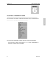
CHAPT ER 6: PRE-PROCESSOR
Line
Section 6.1
Surface Options
Section 6.2
Element Options
Section 6.3
Node Options
Section 6.4
Model Checker
Section 6.5
Set Menu (LS-DYNA)
Section 6.6
Set Menu (NASTRAN)
Section 6.7
Boundary Conditions (LS-DYNA)
Section 6.8
Boundary Conditions (NASTRAN)
Section 6.9
Material Property (LS-DYNA)
Section 6.10
Material Property (NASTRAN)
Section 6.11
Element Property
Section 6.12
iii
Contact Interface
Section 6.13
Dyna Miscellaneous
Section 6.14
Super Element (NASTRAN)
Section 6.15
Mass Menu (LS-DYNA)
Section 6.16
Assembly (LS-DYNA)
Section 6.17
Mass Menu (NASTRAN)
Section 6.18
Assembly (NASTRAN)
Section 6.19
CHAPT ER 7: VPG M ODULES
Road Menu
Section 7.1
Suspension Menu
Section 7.2
Tire Model
Section 7.3
Safety Module
Section 7.4
CHAPT ER 8: ANALYSIS
Analysis
Section 8.1
Control Cards (LS-DYNA)
Section 8.2
Database Cards
Section 8.3
Gravity Load
Section 8.4
Boundary Cards
Section 8.5
Constraint Cards
Section 8.6
Load Cards
Section 8.7
Initial Velocity
Section 8.8
Define Contacts
Section 8.9
Define Curve
Section 8.10
Dyna Input File Options
Section 8.11
Run Analysis
Section 8.12
Write Input File
Section 8.13
CHAPT ER 9: POST PROCESSING
Introduction
Section 9.1
General Overview
Section 9.2
File Manager
Section 9.3
Icon Bar
Section 9.4
File Format
Section 9.5
Configuration File
Section 9.6
File Menu
Section 9.7
Edit Menu
Section 9.8
iv
Tool Menu
Section 9.9
Option Menu
Section 9.10
Post Process
Section 9.11
Graph
Section 9.12
CHAPT ER 10: UT ILIT Y
Viewing Options
Section 10.1
Icon Bar
Section 10.2
Part Control
Section 10.3
Utility
Section 10.4
Display Options
Section 10.5
APPENDICES
APPENDIX A: VPG Capabilities for F.E.A. Analysis Programs
APPENDIX B: VPG Hardware and Software Requirements
APPENDIX C: Supported IGES Entity Types
APPENDIX D: Converting RADIOSS to LS-DYNA
APPENDIX E: Converting LS-DYNA to RADIOSS
APPENDIX F: Converting NASTRAN to LS-DYNA
APPENDIX G: Converting LS-DYNA to NASTRAN
APPENDIX H: Converting RADIOSS to NASTRAN
APPENDIX I: Converting NASTRAN to RADIOSS
APPENDIX J: Converting ADAMS to LS-DYNA
APPENDIX K: VPG Menu
INDEX
v
Chapter 1
Introduction
1
Chapter 1: Introduction
1.1 Documentation
The eta/VPG Documentation consists of Manuals and Tutorials. This manual serves as the
primary description of all eta/VPG functions and provides the user with a description of each of
these functions and the necessary mechanics of how to use them. The Tutorials demonstrate
how to implement the various functions in eta/VPG for use in specific finite element modeling
applications.
This documentation was created to complete the following objectives:
1. Provide a description of general-purpose pre- and post-processor functions for constructing
FEA models and reviewing analysis results.
2. Provide descriptions of the usage of utility modules for meeting VPG-specific application
requirements. Examples of this are tire model generation, road surface library usage,
suspension template usage, fatigue life prediction calculation, and signal processing.
3. Describe methods to interface with external data; reading and writing files to various MCAE
solvers and accepting data from commercial CAD software.
Accompanying this manual is a set of Tutorials specifically designed to introduce modeling and
application topics to the user. The Tutorials provide examples to demonstrate the different
techniques used in creating a VPG simulation and how to use various modeling functions. The
Tutorials also serve as a training guide for new users to gain experience with VPG techniques,
methodology, and software.
In addition to the eta/VPG Manuals and Tutorials, the solver-related features pertaining to
eta/VPG’s dynamic simulations can be found in the LS-DYNA User’s Manual. The LS-DYNA
User’s Manual is the documentation for the LS-DYNA software, developed by Livermore
Software Technology Corporation (www.lstc.com).
1-1
eta/VPG3.0
INTRODUCTION
Chapter
Introduction
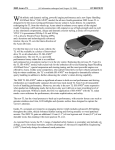
1.2 The History of eta/VPG
The eta/VPG software has its origins in the automotive CAE community, where the need for
efficient finite element modeling tools emerged in the mid to late 1980’s. These tools were
needed to address the drive for shortened vehicle development schedules and the desire to
implement CAE simulations in the design process.
ETA had been an early innovator in the area of finite element pre & post processing, developing
and commercializing the eta/FEMB software in the mid-80’s. This software met the needs of the
automotive CAE engineers and was quickly adopted to help the transformation of the
automotive CAE community.
As the need for more complex simulations arose, there was a simultaneous increase in
low-cost, high-speed computing capacity. This provided the opportunity to create system-level
simulations of events, mimicking the test process more accurately. Prior to this time,
conventional CAE techniques consisted of smaller, specific analyses tailored to a specific task
(such as NVH), separate from the global system-level analysis of the automobile.
The eta/VPG developers were faced with the need for an integrated analysis that included both
component-level and full vehicle applications with the ability to perform real-time simulations.
The analysis would be dynamic and nonlinear -- unlike the static, linear analysis techniques
utilized by the then-current CAE practices.
ETA first tested this concept on simple mechanisms, simulating mechanical systems such as
engine/connecting
rod/piston/crankshaft
systems
and
suspension
mechanisms.
The
mechanisms were simulated as a dynamic, nonlinear system in real-time events. The results
demonstrated that the motion and forces derived from the VPG simulation were the same as
the rigid body linkage motion simulation results produced from conventional multibody
dynamics software. However, when implementing flexible bodies (FE), the benefit of obtaining
realistic stress and strain results of flexible components from the VPG simulation in an
event-based fashion produced valuable analysis data that could not be generated in traditional
FEA approaches.
ETA engineers moved another step forward by simulating a rotating tire impact in a pothole
event. A tire model was developed to include a control volume technique to simulate the tire air
pressure behavior under an impact condition. The simulation of the frictional contact of the tire
model with the rigid road surface was extremely realistic and correlated with existing tire data.
To complete the system-level simulation, the need for dynamic test-based boundary conditions
1-2
eta/VPG3.0
INTRODUCTION
Chapter 1
Chapter 1
Introduction
was necessary. ETA therefore formed an agreement with MGA Research Corporation to model
road surface profiles that could be digitized from the proving ground construction drawings in a
CAD surface format. FEA mesh could be generated from the CAD surface data and produced a
selection of specific road profiles representing the characteristics of the proving ground testing
conditions.
After years of development and evaluation, it has been confirmed that VPG technology
produces repeatable, reliable, and correlated analysis results. The level of confidence from
users and correlation results has lead to aggressive simulation use and a broad application
scope.
Dr. John Hallquist, at Livermore Software Technology Corporation (LSTC) has been
instrumental in the development of the VPG application technology by implementing various
features and functions of LS-DYNA to meet VPG requirements. This partnership with LSTC has
allowed the VPG methodology to grow in scope of application and reliability.
The release of VPG 1.0 in 1998 was an effort to address the specific needs of system modeling
by combining the tools created for tire modeling and suspension modeling with the finite element
meshing and associated tools found within the eta/FEMB product.
As usage progressed and the needs of users expanded, fatigue analysis software was
embedded into VPG, as were the signal processing tools used in NVH post processing.
The dual nature of many of the models created in VPG and the desire to construct one model for
use in several types of simulations drove the development of the VPG/Safety module. This
module was incorporated into eta/VPG version 2.0, which was released in 2002.
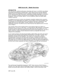
1.3 VPG Methodology for Event Simulations
Virtual Proving Ground (VPG) is a general term used to reference a simulation methodology
using the tire and proving ground road surface approach.
The VPG method is a set of techniques used with an explicit, nonlinear, dynamic analysis
program, which allows for the complete analysis of a mechanical system, including all joints,
bushings, materials, and geometric non-linearities using an event-based analysis. The class of
problems targeted is those in which a mechanical system is to be analyzed in a dynamic sense.
In other words, when a mechanical system is in use, the displacements, forces, accelerations,
and stresses occur in real-time. The VPG method allows for the calculation of all of these
quantities simultaneously, using a single analysis run.
1-3
eta/VPG3.0
INTRODUCTION
the company’s vehicle proving ground facility located in Burlington, Wisconsin. ETA created
Chapter 1
Introduction
ground durability cycle, the concept can also be applied to other dynamic mechanical systems.
1.4 eta/VPG Software Package
eta/Virtual Proving Ground (eta/VPG) is a fully integrated, dynamic, nonlinear, finite element
software package used to create, analyze, edit, and visualize dynamic, nonlinear engineering
problems. The software includes an integrated preprocessor, post processor, and solver.
VPG is a complete CAE software toolset for applying theory and engineering principles
common in areas of mechanical and structural engineering.
eta/VPG provides a single
package for use in analysis of multi-body dynamics problems, linear static, nonlinear static, and
dynamic nonlinear finite element analysis.
eta/VPG's strength lies in its ability to integrate problems that are treated as multidisciplinary by
other software packages. eta/VPG allows the user to combine multi-body dynamics problems
with structural finite element analysis problems, providing real-time kinematics or dynamics as
well as the stress or strain response of the structure in real time.
eta/VPG consists of three primary modules, the VPG/PrePost module, the VPG/Structure
Module and the VPG/Safety Module. Each module may operate independently, and usage is
controlled via licensing options.
VPG/PrePost is a general-purpose, full-featured modeling software for the construction and
results display of finite element models. This module allows users to import CAD data,
construct CAD data, import existing FE models, and construct the geometry and mesh required
for finite element analysis. All boundary conditions and material properties may also be created
in this module. Output of the model in various finite element solver formats is available.
VPG/Structure contains many special features designed specifically for system level or full
vehicle analysis. These features allow for easy modeling of joints and bushings, finite element
meshes, boundary conditions, materials, properties, suspension system components, tire
models, and road surface models.
VPG/Safety was introduced in release 2.0 of eta/VPG. This module is targeted at LS-DYNA
users who wish to construct vehicle impact and occupant safety simulations. This module is
based on two integral sub-components: a crash tool library and the test procedures associated
with a specific governmental regulation. The Crash Tool Library contains the dummy or barrier
needed to perform a specific analysis. For instance, a European Side Impact test requires an
EEC Side Impact Barrier and a EUROSID dummy model. These are combined with the testing
1-4
eta/VPG3.0
INTRODUCTION
While VPG methodology was initially developed for full vehicle simulations based on a proving
Chapter 1
Introduction
procedure (vehicle velocity, etc.) and measurement criteria to establish a process. VPG/Safety
insurance institute test procedures are contained within VPG/Safety.
1.5 eta/VPG Special Features
eta/VPG was initially designed with unique features specifically for virtual proving ground
simulations. These features are not found in competing general purpose pre- and
post-processors. The development of these features and functions was necessary to satisfy the
following VPG requirements:
1. Generation of complicated full vehicle/full system models and retention of complex
non-linear material properties, contact definitions, etc.
2. Generation and retention of user-defined libraries and modules such as a tire library, proving
ground road surface libraries, etc.
3. Post-processing of potentially large amounts of analysis data (displacement, forces,
acceleration, stress, and strain) derived from time domain solution of multiple events and the
conversion from time domain results into frequency domain results (frequency, mode shape
and PSD, etc.).
4. Post-processing of stress and strain results of multiple events and conducting the fatigue life
prediction.
5. Modeling and set-up of vehicle impact analyses using FMVSS, ECE, and Insurance Institute
standard testing procedures.
The key features are briefly described below. A more detailed explanation of these features is
found in Chapter 7.
LS-DYNA 970 Interface Module
eta/VPG incorporates a complete, direct LS-DYNA version 970 interface. eta/VPG reads and
writes all LS-DYNA 970 cards, eliminating the need for text editing of the input deck. It creates
and retains all material nonlinear properties, contact definitions, and loading conditions.
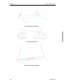
Tire Model Generator
eta/VPG's tire model generator allows for easy construction of tire models. The tire model
generation tool employs specific tire geometry and inflation pressure to automatically construct
a three-dimensional finite element model. Tire models are used for both vehicle durability and
1-5
eta/VPG3.0
INTRODUCTION
follows that process to set up the simulation model. A total of 21 different governmental or
Chapter 1
Introduction
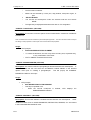
Specialized tire models are available for users requiring detailed models of tires. These models
are suitable for use in detailed, tire-focused analyses and require detailed material information.
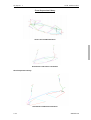
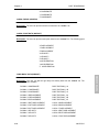
Suspension Model Generator
eta/VPG's sophisticated suspension model generator automates the FEA modeling of the most
popular suspension types.
Suspensions may be modeled using flexible, finite element
representations or rigid members. Material properties of the suspension component can be
specified using the nonlinear stress-strain characteristics of the material. Included in eta/
VPG's suspension libraries are these suspension types:
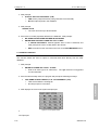
•
MCPHERSON H-ARM
•
TRAILING ARM
•
MCPHERSON A-ARM
•
HOTCHKISS
•
SOLIDAXLE
•
TWIST BEAM
•
FIVE LINK
•
HONDA 5-LINK
•
QUADRA LINK
•
SHORT LONG ARM
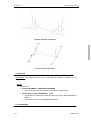
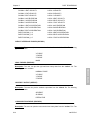
Road Surface Library
eta/VPG'S road surfaces form a full vehicle durability evaluation platform ready for kinematics
and stress analyses of component, subsystem, and vehicular models. Road surfaces are
generated using any 3D data or selected from the VPG library. The Library contains digitized
models of the following MGA Proving Ground road surfaces:
POTHOLE TRACKS
RIPPLE TRACKS
ALTERNATE ROLL SURFACE
WASHBOARDS
COBBLESTONE TRACKS
CHATTERSTRIP
BODY TWIST LANE
PAVE SURFACE
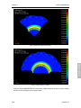
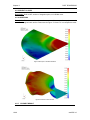
Fatigue Analysis Program Module
eta/VPG's built in fatigue post processor automatically performs a fatigue life analysis
prediction to identify the key damage events and stress amplitudes. This data is then used to
1-6
eta/VPG3.0
INTRODUCTION
NVH applications.
Chapter 1
Introduction
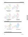
calculate the percentage of fatigue life remaining at the completion of the durability cycle.
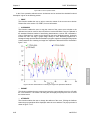
Signal Processing Module
eta/VPG performs full vehicle NVH studies on simulated proving ground surfaces. eta/VPG
automatically converts time-domain analysis results into frequency-domain via FFT (Fast
Fourier Transform). eta/VPG determines both low and mid range frequencies up to 250Hz for
operating mode shapes, frequencies, structural and airborne noise, and frequency responses
such as idle shake, rough road, power train, and wheel imbalance.
1-7
eta/VPG3.0
INTRODUCTION
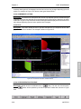
eta/VPG displays these results in easily read, combined fatigue life contour plots.
Chapter 2
An Overview of eta/VPG Features
2
Chapter
This chapter provides an overview of the main features of eta/VPG. Detailed descriptions of the use
of these features are provided in subsequent chapters.
2.1 GENERAL
The eta/VPG Processor has a complete graphical user interface that is operated on Windows
(Windows NT and above) and UNIX/Linux-based workstations including IBM, HP, SUN, and SGI
operating systems. The model generation, input file preparation, and results processing activities
are all performed in an identical environment. The solution can be executed on both local and/or
remote server systems.
2.2 PRE PROCESSOR
eta/VPG's extensive Preprocessing capabilities contain all of the functions necessary for
expedient, high quality finite element modeling. Users can read in data with VPG's CAD interface,
build their model from scratch, read in an existing model, or a combination of the approaches.
CAD Interface
eta/VPG enables users to read in CAD geometry data from the following CAD systems:
Catia Version 4
Catia Version 5
Unigraphics version 18
Unigraphics NX
Parasolid
STEP
IGES
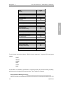
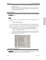
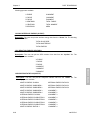
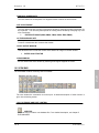
The IGES interface reads files generated from any CAD system. Supported IGES entity types
include:
2-1
eta/VPG3.0
FEATURES
Chapter 2: An Overview of eta/VPG Features
An Overview of eta/VPG Features
Name
Null Entity
Type
0
Circular Arc Entity
100
Composite Curve Entity
102
Conic Arc Entity
104
Copious Data Entity
106
Plane Entity
108
Line Entity
110
Parametric Spline Curve Entity
112
Parametric Spline Surface Entity
114
Point Entity
116
Ruled Surface Entity
118
Surface of Revolution Entity
120
Tabulated Cylinder Entity
122
Transformation Matrix Entity
124
Rational B-Spline Curve Entity
126
Rational B-Spline Surface Entity
128
Offset Surface Entity
149
Boundary Entity
141
Curve on a Parametric Surface Entity
142
Bounded Surface Entity
143
Trimmed (Parametric) Surface Entity
144
Subfigure Definition Entity
308
Associativity Instance Entity
402
Property Entity
406
Singular Subfigure Instance Entity
408
FEATURES
Chapter 2
For the German automotive industry, VDA file format is supported. Supported VDA entity types
include:
POINT
CIRCLE
CURVE
SURF
CONS
FACE
If CAD data is not available, eta/VPG has a complete geometry and surface building capability,
which acts as an integrated CAD data generator. This is detailed in Chapter 6.
Extensive Model Building Functions
eta/VPG includes a comprehensive selection of functions for creating and modifying line data
2-2
eta/VPG3.0
Chapter 2
An Overview of eta/VPG Features
and CAD surfaces. In addition to automeshing functions, element generation through 2-line,
4-line, 6-line and 8-line mesh creates beam, shell, and solid elements.
Comprehensive Model Modification Functions
All aspects of the model may be modified using the pre-processing menus. All defined material,
elements, nodes, contacts and analysis parameters may be modified, deleted, copied, etc., as
required by the user.
Full System Assembly
This includes part replacement and connectivity attributes of the model.
Automeshing
eta/VPG's automeshing function easily eliminates 90% of the time required to mesh trimmed
and standard surfaces. The automeshing function creates quadrilateral elements with a
minimum of triangular elements.
Various automeshing algorithms are available, including Triangular Meshing, Paving Mesh and
Topology Automeshing.
Material/ Element Properties
eta/VPG supports all LS-DYNA and NASTRAN material and element property cards.
eta/VPG's ability to create and assign material and element properties directly on a displayed
model greatly reduces the amount of editing required. Definition cards appear at specific
junctions in the session prompting the user for material/element properties.
Users also have the option to specify the analysis software (NASTRAN, LS-DYNA, RADIOSS,
PAMCRASH) prior to assigning properties.
Contact Interface
eta/VPG seamlessly interfaces with LS-DYNA, allowing the user to create and assign impact,
sliding, or automatic interfaces for VPG applications. eta/VPG displays contact properties in
easily read and modified CONTACT CARDS with a high degree of speed and flexibility.
Boundary Conditions
eta/VPG's BOUNDARY CONDITIONS menu allows the user to quickly create and verify
constraints and loads on VPG models.
Model Integrity Checking Functions
The functions in eta/VPG's MODEL CHECKER menu quickly validate models for element
orientation, size, skew, connectivity, and interior angles. Model validation default values are
2-3
eta/VPG3.0
FEATURES
The ASSEMBLY menu allows users to create assemblies which may be modified as a group.
Chapter 2
An Overview of eta/VPG Features
easily adjusted to suit the user's needs.
Constraints
eta/VPG supports all LS-DYNA Constraint Cards for quick, easy definition and manipulation of
joints, welds, rivets, etc.
2.3 POST-PROCESSOR
eta/VPG integrates a general-purpose, complete post-processor for data post processing of
Analysis results are seamlessly input from VPG's double precision
LS-DYNA solver to the post processor for quick, easy interpretation of analysis results. Once
entered, VPG's full complement of post processing functions allow the user to graphically display
and manipulate simulation result files with contour and deformation animation, contour plots and
fills, and geometry deformation.
VPG's post-processing functions allow the user numerous ways of animating and viewing the
analysis results. The user has the options of animating select frames, viewing single frames,
altering the time step, rotating the model, or viewing only select parts of the model.
The post processing function automatically prompts the user for the result file when activated.
VPG post processes the following types of result data:
D3PLOT (d3plot01, etc.)
DYNA DEFORMED GEOMETRY (.defgeo)
HISTORY (.his)
NASTRAN PUNCH (.pch)
NASTRAN OUTPUT2 (.op2)
NASTRAN PACKED PUNCH (.pac)
VPG provides an option to create a more compact post-processing file. This binary file, called a
“pp” file due to its extension “ *.pp ”, is created after reading the result file into eta/VPG. Once
the .pp file is created, the user may read this file to save both disk storage space and time when
reloading the analysis results. The .pp file requires less space than the analysis result file used to
create it and can be used for all subsequent post processing functions.
It also requires
significantly less time to load the .pp file.
Fatigue
VPG allows the user to generate and post process fatigue result files from within the VPG
Interface.
2-4
eta/VPG3.0
FEATURES
analysis result files.
Chapter 2
An Overview of eta/VPG Features
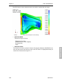
ANIMATE CONTOUR
This function is used to map the stresses, strains, and strain energy of the model across time.
Animations can be edited to even, odd, or specified frames.
ANIMATE DEFORMATION
This command allows the user to animate displacements within the model in real time.
Animations can be edited to even, odd, or specified frames.
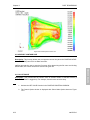
CONTOUR FILL
the user to view the contour values by superimposing a fill-color contour image onto the model.
The values are displayed in a color legend in the upper right hand corner of the screen.
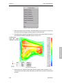
CONTOUR LINES
This function, similar to the CONTOUR FILL function, allows the user to check the model's
contour values for a single step. A color, wire frame, contour-line plot of the component result
is superimposed onto the current model.
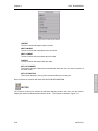
DEFORMED SHAPE
This command displays the displacement results of the model for a single step. The
undeformed model shape is displayed in white. The model can be animated to show the
transition between the undeformed and deformed model.
Element Stress
This function displays the stress results of each individual element as opposed to the contour
plot functions, which display the stress results in terms of the average stress at each node. A
color legend for the corresponding color values is displayed in the upper right hand corner of the
screen.
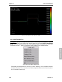
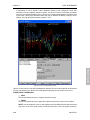
Time History Plot
eta/VPG's TIME HISTORY PLOT functions enable the user to visualize the results of an
analysis with XY plots. VPG offers a wide range of tools to manipulate the information on the
display screen with labels, colors, multiple graphs, and a host of advanced filtering techniques
e.g., FIR, Butterworth, SAE, scaling, smoothing, and averaging.
FFT (Fast Fourier Transform)
The TIME <--> FREQUENCY function allows the user to convert time domain to frequency
domain response for signal processing analysis. The FFT equation is used to convert time
domain to frequency domain and frequency domain to time domain for any graph plot.
2-5
eta/VPG3.0
FEATURES
This function maps stresses, strains, and strain energy in the model for a single step. It allows
Chapter 2
An Overview of eta/VPG Features
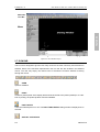
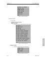
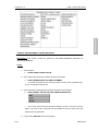
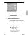
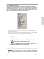
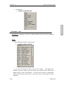
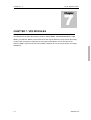
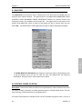
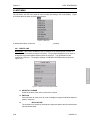
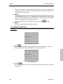
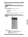
2.4 MENU SYSTEM
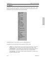
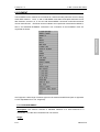
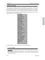
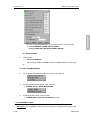
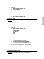
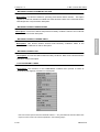
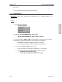
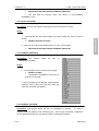
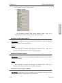
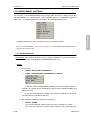
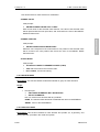
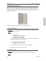
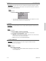
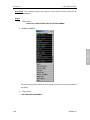
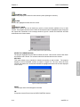
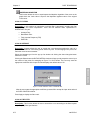
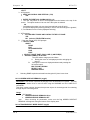
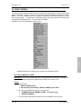
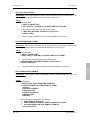
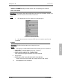
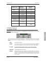
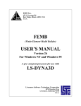
The program starts in the MAIN menu (see figure 2.3.1) and branches out into submenus. The
user selects a sub-menu by mouse pick or keyboard entry. Descriptions for these menu options
are located in their respective sections.
FEATURES
Figure 2.3.1 Main Menu
2-6
eta/VPG3.0
An Overview of eta/VPG Features
FILE
Imports and exports data to and from VPG.
PART
Creation, display control and manipulation of part entities.
PRE
Contains a menu of preprocessing functions.
LINE
Creates and modifies line/surface data.
SURFACE OPTIONS
Creates and modifies surfaces in VPG.
ELEMENT OPTIONS
Creates and modifies elements.
NODE OPTIONS
Creates, copies, transforms, and manipulates nodes.
MODEL CHECKER
Checks element criteria (warpage, boundary, aspect ratio,
etc.).
SET MENU
Creates node and element sets for Super element files
substructure files, etc.
BOUNDARY CONDITIONS
Creates and verifies constraints and loads on a finite
MATERIAL
Creates and assigns material properties.
ELEMENT PROPERTY
Creates and assigns element properties.
CONTACT INTERFACE
Creates and modifies sliding/rigid wall interfaces for
element model.
LS-DYNA.
DYNA MISCELLANEOUS
Handles distinct LS-DYNA miscellaneous data.
NASTRAN
Handles distinct NASTRAN miscellaneous data.
MISCELLANEOUS
SUPER ELEMENT
Assigns and modifies SUPER ELEMENT ID numbers
(only for NASTRAN application).
2-7
MASS MENU
Creates and modifies MASS.
ASSEMBLY
Arrange and assemble parts’ or part sets’ connections.
eta/VPG3.0
FEATURES
Chapter 2
Chapter 2
An Overview of eta/VPG Features
ROAD MENU
Defines road surfaces.
SUSPENSION MENU
Defines and auto-generates front and rear automotive
TIRE MODEL
Defines and auto-generates tire models.
SAFETY
Analyzes vehicle impact and occupants’ safety.
ANALYSIS
Analyzes proving ground events.
FATIGUE
Analyzes element fatigue.
POST
Provides options for viewing the results of an analysis.
GRAPH
Plots dynamic characteristics of the structure vs. time,
velocity, etc.
UTILITIES
Provides a series of VPG “tool kit” functions.
VIEWING OPTIONS
Manipulates the display, position, and perspective of the
model.
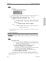
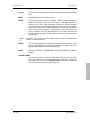
2.5 FUNCTION KEYS
Function keys 1 through 8 act as shortcuts the most frequently used menus.
The F1
(Function key 1) is reserved for the Main Menu.
F1
Main Menu
Model Checker
F2
Element Options
F6
Node Options
F3
File Open
F7
Surface Options
F4
Line
F8
Pre-Processor
F5
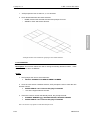
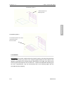
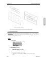
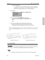
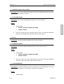
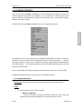
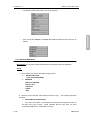
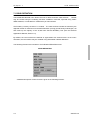
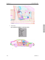
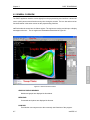
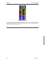
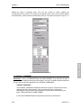
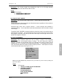
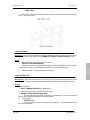
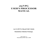
2.6 DISPLAY WINDOW
VPG breaks the screen into six distinct regions. The regions are used to receive input or
display messages for the user. The six regions are illustrated on the following page. See
Figure 2.5.1.
1. DRAWING WINDOW -- Models and definition cards are displayed in this area.
2. MENU BAR – The groups of menus containing all eta/VPG modules.
3. ICON BAR-- This group of commands dynamically manipulates the display,
position, and perspective of a model.
4. MENU -- Commands and the Command’s Options are displayed in this area. They
can be accessed via the keyboard mouse.
5. DIALOGUE WINDOW -- VPG displays comments and messages to the user
and accepts keyboard entry commands in the dialogue window.
6. DISPLAY PARAMETER OPTIONS WINDOW -- These commands set the plot
options for the current model.
2-8
eta/VPG3.0
FEATURES
suspensions.
Chapter 2
An Overview of eta/VPG Features
Menu Bar
Icon Bar
FEATURES
Menu
Dialogue Window
Display
Figure 2.5.1 VPG Window Layout
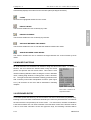
2.7 ICON BAR
The icon bar is designed to give the user easy access to the most commonly used functions in
eta/Post. Some of the functions represented in the icon bar are also located in the different
menus. The user may simply click these icons to activate the functions instead of clicking
through the menus.
OPEN
Opens a database.
PRINT
Creates a postscript file of the display area and sends the file to the printer (default) or to a file.
Prior to printing, the postscript driver must be initialized.
PART ON/OFF
Turns the selected parts on or off. The PART TURN ON/OFF dialog window is displayed once
selected.
VIRTUAL X ROTATION
2-9
eta/VPG3.0
Chapter 2
An Overview of eta/VPG Features
The displayed model will dynamically rotate about the global X-axis when the cursor is moved
up or down.
VIRTUAL Y ROTATION
The displayed model will dynamically rotate about the global Y-axis when the cursor is moved
up or down.
The displayed model will dynamically rotate about the global Z-axis when the cursor is moved
up or down.
SCREEN X ROTATION
The displayed model will dynamically rotate about the screen X-axis when the cursor is moved
up or down.
SCREEN Y ROTATION
The displayed model will dynamically rotate about the screen Y-axis when the cursor is moved
up or down.
SCREEN Z ROTATION
The displayed model will dynamically rotate about the screen Z-axis when the cursor is moved
up or down.
Note:
Screen axis rotation uses the display screen as a plane of rotation. The screen
X-axis is horizontal. The screen Y-axis vertical and screen Z-axis is perpendicular to
screen X and Y.
FREE ROTATION
This function is a combination of SX and SY. Moving the mouse up/down manipulates SX.
Moving the mouse left/right manipulates SY. Moving the mouse diagonally combines the
movements of both commands. Clicking the left mouse button stops the rotation. This function
can also be activated by pressing Control and Left mouse button, and exits by releasing left
mouse button.
PAN
This command enables the user to translate the model by following the movement of the cursor.
If the cursor is moved off the screen, the cursor reappears at the center of the screen. Clicking
2-10
eta/VPG3.0
FEATURES
VIRTUAL Z ROTATION
Chapter 2
An Overview of eta/VPG Features
the left mouse button stops the pan. This function can also be activated by pressing Control and
Middle mouse button, and exits by releasing Middle mouse button.
CURSOR ZOOM
The user picks a point about which to zoom. The model is centered about this point and the
user may move the cursor up or down to zoom in or out. This function can also be activated by
pressing Control and Right mouse button, and exits by releasing Right mouse button.
If the cursor is moved off the screen in functions ROTATE, PAN or CURSOR ROOM,
the cursor re-appears the opposite of the screen automatically.
WINDOW ZOOM
The user defines the corners of the zoom window by positioning the cursor on the display
screen. The user presses the left mouse button and drags the cursor diagonally down until the
desired window size is reached. After releasing the left button, the section included in the
window is displayed in full screen.
FREE HAND ZOOM
The user defines a free region by pressing the left mouse button and dragging the cursor on the
display screen. Release the left button, and the section included the region is displayed in full
screen.
FILL
Rescales the model to include all entities belonging to parts that are currently turned on. FILL
automatically zooms in or out until the model fits the viewing area of the screen.
TOP VIEW
Automatically displays the model from the TOP or in the XY-plane.
SIDE VIEW
Automatically displays the model from the SIDE or in the XZ-plane.
REAR VIEW
Automatically displays the model from the REAR or in the YZ-plane.
ISOMETRIC VIEW
2-11
eta/VPG3.0
FEATURES
Note:
Chapter 2
An Overview of eta/VPG Features
Automatically displays the model from the isometric plane (60-degree isometric).
CLEAR
Removes the highlighted entities from the screen.
IDENTIFY NODE
FEATURES
This function enables the user to identify any node.
IDENDFIY ELEMENT
This function enables the user to identify any element.
DISTANCE BETWEEN TWO NODES
This function enables the user to calculate the distance between two nodes.
ANGLE BETWEEN THREE NODES
This function enables the user to measure the angle between two vectors formed by three
nodes.
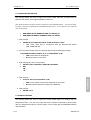
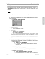
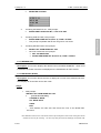
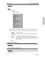
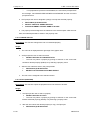
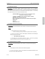
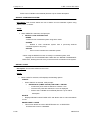
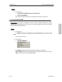
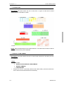
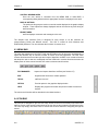
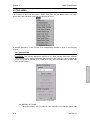
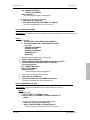
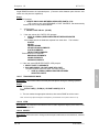
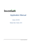
2.8 MOUSE FUNCTIONS
All VPG functions are accessible via selection using the left mouse button. To access a
function, the user selects the desired button using the mouse
pointer and presses the left mouse button. This button is also
used for selecting definition cards, locating the cursor in definition
cards, creating drag windows, locating points, nodes, elements,
etc. The right mouse button activates a floating, pull-down menu
with commonly used model manipulation functions (See Figure
2.6.1). All functions on the menu will be described in following
chapters.
Figure 2.6.1 Floating Pull
Down Menu accessed via
Right Mouse Button
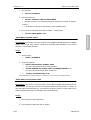
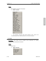
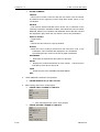
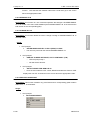
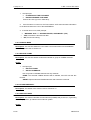
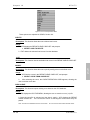
2.9 KEYBOARD ENTRY
To increase speed and efficiency, all VPG functions can also be accessed by keyboard entry.
Entering a one or two-letter combination followed by the return key activates each command of
the menu that the user presently has on the screen. For main menus, the letter combination
is the first two letters of a one-word command or the first letter of each of the first two words of
a two or more word command. As the user types the keys, the matching command will be
2-12
eta/VPG3.0
Chapter 2
An Overview of eta/VPG Features
highlighted. For example, the keystroke entry for the command ELEMENT OPTIONS/
SURFACE MESH in the above menu would be "s", "m" followed by the RETURN key. For the
ELEMENT OPTIONS/ MODIFY command, the keystroke entry would be "m", "o" followed by
the RETURN key. For control keys, the user need only type the first letter to access the
function.
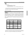
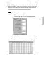
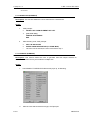
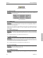
2.10 SPECIFICATIONS
The standard version of VPG has the following specifications for model databases:
Maximum Count
LINES
FEATURES
Entity
150,000
POINTS
1,500,000
SURFACES
32,000
2,500,000 Edge Points
400,000 Control Points
GRIDS
ELEMENTS
125,000
1,000,000
PROPERTIES
1,000
PIDS
1,000
2.11 LINE DATA
VPG's built-in translator converts and filters line data from the following programs into a neutral
line format:
IGES (lines and surfaces)
DXF file formats
VDA file
There are additional external translators to support CAD files generated from the following
programs:
CATIA4
CATIA5
STEP
Unigraphics versions 18 and NX
2.12 CONVENTIONS
This manual is designed to reduce the amount of reading material on the page and maintain
text clarity.
Several fonts and symbols are implemented throughout the manual. An
example is given at the bottom of the page.
2-13
eta/VPG3.0
Chapter 2
An Overview of eta/VPG Features
FIXED FONT
-This font indicates text found within VPG e.g., menu
(ALL CAPS, BOLD)
- Names, subsections, commands, and options within commands,
etc.
Proportional Font - This font indicates explanatory text e.g., command descriptions,
notes, and section titles.
ALL CAPITALS
- This font indicates a function, menu name, card, command, etc.
found in explanatory text.
>
- The greater than symbol directs the user to read the text displayed in VPG's
DIALOGUE WINDOW.
- The question mark directs the user to select an option that is listed in VPG's
MENU WINDOW.
•
- The bullet signals a description of the previous command or situation.
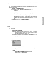
-CREATE
4 - PLATE ELEMENT
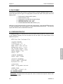
This section covers the options for the PLATE ELEMENT subsection of
CREATE ELEMENTS.
1.VPG prompts:
>
PICK NODES/POINTS FOR ELEMENT
?
NODE
POINT
•
To create the elements, the user may select a node, point, keyboard
entry, or any combination of the three.
•
•
An element will be created after three or four nodes/points are selected.
EXIT or ABORT will exit this function.
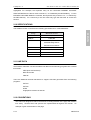
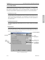
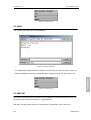
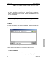
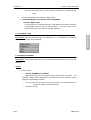
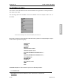
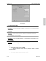
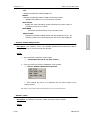
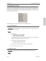
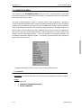
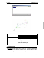
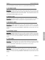
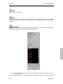
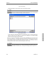
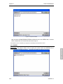
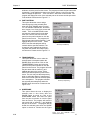
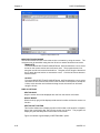
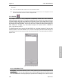
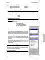
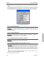
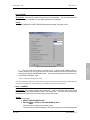
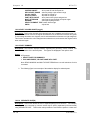
2.13 VPG OPEN FILE WINDOW
The VPG OPEN FILE WINDOW allows users to access files and directories. The
DIRECTORIES and FILES windows are accompanied. VPG OPEN FILE WINDOW is a
convenient tool for viewing of directories and files.
2-14
eta/VPG3.0
FEATURES
?
An Overview of eta/VPG Features
FEATURES
Chapter 2
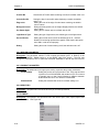
Figure 2.12.1 Open File Window
All files listed in the OPEN FILE window are displayed from the current directory based on a
filter (filename extension such as .vpg). The current directory is listed at the top of the LOOK
IN drop-down menu. Changing the filter parameter in the File Type drop-down menu sets the
file type filter. The FILE NAME window allows the user to enter the file name and directory
manually.
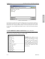
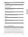
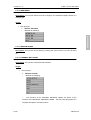
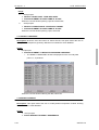
2.14 RECOMMENDED NAMING CONVENTION (.his, .lin, .bin, etc.)
The protocol for naming files during a VPG session includes attaching suffixes to the file
names that specify the file types. Examples of suffixes include:
Example: When reading in a line
data file, VPG prompts for a line data
file name (all file Names in that
directory with the suffix .lin are listed in
the options area).
The user then
selects the appropriate file name. This
practice makes the file name selection
convenient and organizes the user's
work directory.
2-15
eta/VPG3.0
Chapter 2
An Overview of eta/VPG Features
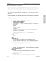
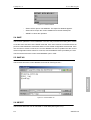
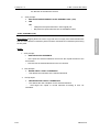
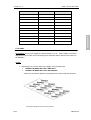
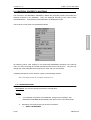
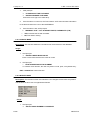
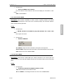
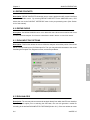
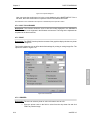
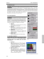
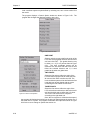
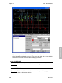
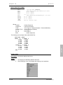
2.15 LS-DYNA CARDS
eta/VPG supports all LS-DYNA input data from versions 970 and earlier.
As a result, models
generated using eta/VPG require no external editing to complete the file for execution. The
input “cards” are arranged as they are in the LS-DYNA manual.
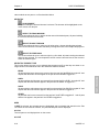
eta/VPG displays the
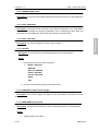
necessary input parameters in windows as shown in Figure 2.14.1 and as described below.
CARD SELECT BUTTON
to jump conveniently to the desired card. The card button is not an option when only one
card is needed to define the selected property or the number of cards is dependent on
user-defined values.
CARD DESCRIPTION FIELD
The CARD DESCRIPTION FIELD allows the user to enter a name for the defined
properties.
EDITING FIELDS
VPG's smart editing field only allows values within the specified range to be entered. If
the value entered is beyond the LS-DYNA defined range VPG prompts the user when the
user tries to move to another field or card.
Card Select Button
Card Title
.
Card
Description
Editing Field
Field
Description
Field Editing
Push Button
Figure 2.14.1 Card Definition Window
2-16
eta/VPG3.0
FEATURES
The CARD SELECT BUTTON displays the number of definition cards and allows the user
Chapter 2
An Overview of eta/VPG Features
FIELD DESCRIPTION
The field description indicates the value to be added to the editing field.
If the field
description text is gray, it indicates that the value entered in that field is dependent on
another field that must be edited first.
EDITING PUSH BUTTON
An editing button forwards the user through a series of prompts, menus, or cards that
FEATURES
results in a valid value for the chosen field.
OK
Accepts and saves the defined input data.
NEXT
Forwards the user to the next input data window for this entity.
PREVIOUS
Forwards the user to the previous input window for this entity.
CANCEL
Exits without saving or defining the data.
ENTER
Pressing ENTER at any time during input data definition accepts and saves the defined
data.
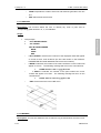
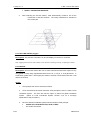
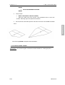
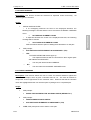
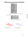
2.16 LOCAL COORDINATE SYSTEM
VPG refers to the local coordinate system to translate, rotate, mirror, copy, and generate
points, lines, and nodes.
When such a function is selected, the program will automatically
prompt the user to generate a local system designated as the UVW coordinate frame. One,
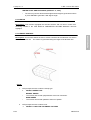
two, or three reference points are required to establish a local coordinate system.
For a three-point system, the first reference point defines the local origin. The second
reference, which extends from the first reference point, defines the direction of the local U-axis.
The third reference point defines the local UV plane. The local W-axis is defined in the UV
plane and is perpendicular to the U-axis. The local W-axis is then defined according to the
2-17
eta/VPG3.0
Chapter 2
An Overview of eta/VPG Features
right hand rule perpendicular to the UV plane.
For the two-point option, DONE should be selected after the second reference point is
defined. The local W-axis lies along the vector from the origin to the second reference
point, the V-axis lies in the VW plane, and the U-axis is defined by the right hand rule.
Note:
All rotational commands (generating arcs, copying with rotation, etc.) are executed about the local W- or
global Z-axis.
local origin then enters one of the X, Y, or Z options that are listed to define the local W
along one of the global axes.
1.When creating a local coordinate system, VPG prompts:
>
CREATE LOCAL COORDINATES
PICK NODE/PT FOR ORIGIN
•
VPG prompts for a desired coordinate system (local or global) in the
options area.
?
ABORT
GLOBAL SYSTEM
KEY IN X, Y, Z
•
This signals the user to key in the origin of the local coordinate system.
>
ENTER X, Y, Z COORDINATES
•
The user enters the values for the X, Y, and Z coordinates, e.g.,
100,0, and 0.
NODE
•
Default
POINT
SHOW LAST C.S.
•
Once the last coordinate system has been displayed, see step 3.
•
The user may select a node or a point, enter a coordinate by keyboard, or
use any combination of these options to create a local coordinate system.
2.Once a reference point has been selected, VPG prompts:
>
PICK NEXT POINT OR NODE
?
ABORT
DONE
•
After the user selects 2 reference points, VPG displays the coordinate
system and continues to step 3.
KEY IN XYZ
•
The user may enter up to 3 reference points globally to define a
local coordinate system.
INCREMENTAL XYZ
•
2-18
The user may enter DX, DY, and DZ from the previous reference
eta/VPG3.0
FEATURES
For the one reference point option, the user selects a point or node on the screen as the
Chapter 2
An Overview of eta/VPG Features
point to define a local coordinate system.
NODE
•
The user may select up to 3 nodes to define a coordinate system.
POINT
•
The user may select up to 3 points to define a coordinate system.
REJECT LAST
•
This allows the user to deselect the last reference point during the
selection process.
X AS LOCAL W AXIS
This defines a local coordinate system that is parallel to the global axis with
the local W along the global X-axis and the local origin at the first reference
point.
Y AS LOCAL W AXIS
•
This defines a local coordinate system that is parallel to the global axis with
the local W along the global Y-axis and the local origin at the first reference
point.
Z AS LOCAL W AXIS
•
This defines a local coordinate system parallel to the global axis with the
local W along the global Z-axis and the local origin at the first reference
point.
3. Once the user defines the desired coordinate system, VPG displays it and
prompts:
>
ACCEPT? (Y/N/A)
?
YES
•
VPG prompts for the next command.
NO
•
The user returns to step 1.
ABORT
•
The user returns to the menu.
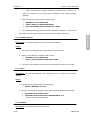
2.17 ENTITY SELECTION
In certain commands such as COPY, DELETE, etc., VPG prompts the user to select elements,
nodes, lines, surfaces, etc. A list of options will appear in the MENU WINDOW. The default selection option is cursor pick at the entity. Other commonly used
selection options are described below:
WINDOW
A window (drag-window) is defined by clicking the left mouse button, dragging the cursor
diagonally across the screen until the desired entities are within the window, and releasing
the left mouse button to complete the selection. If an entity is partially outside the window,
it will not be selected.
2-19
eta/VPG3.0
FEATURES
•
Chapter 2
An Overview of eta/VPG Features
MULTI-PT REGION
A multi-point region (polygon) is defined by clicking the left mouse button in succession to
enclose the desired polygon region. Click on the right mouse button to reject the last
defined point. Click on the middle button to complete the region. Entities within this region
will be selected. If part of an entity is outside of the region, it will not be selected.
PART
The part names will be listed in the menu area. Pick the name from the part list or pick an
MENU WINDOW. All entities in the part will be selected.
REJECT LAST
This option negates the last selection whether from single cursor pick or a group of entities
selected by any of the above options.
EXCLUDE ON/OFF
This option works like a toggle switch. If turned on, all the subsequent selected entities will
be removed from the previously selected list. The user may toggle this option on and off
during the course of the selection.
TYPE
This option is used to control the type of elements to be selected. If DONE is selected
immediately after selecting TYPE, all elements of this type will be selected. Otherwise,
other options may be used to limit the selection of elements.
Note: The TYPE function is specific to the selection of elements.
SURFACE
This function is used to select elements created from a surface by the SURFACE MESH
command.
Note: The SURFACE function is specific to the selection of elements.
2-20
eta/VPG3.0
FEATURES
entity from the screen to select the part. Selected parts will be highlighted in white in the
Chapter 3
G e t t i n g Sta r t e d
3
Chapter
Chapter 3: Getting Started
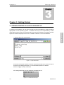
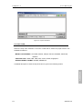
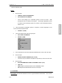
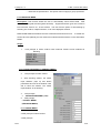
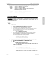
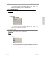
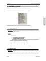
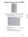
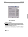
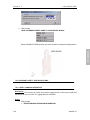
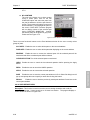
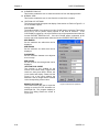
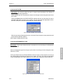
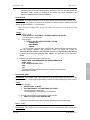
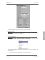
3.1 OPENING/CREATING AN eta/VPG DATABASE FILE
To start the VPG software, the user must execute the VPG executable file, using the method
clicking the shortcut to the VPG executable file. Once the VPG software is activated, the VPG
Open File window is displayed for the user to OPEN or CREATE a new VPG database.
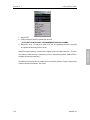
1. See the Open File window below.
Figure 3.1.1 Open File Window
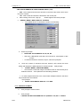
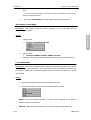
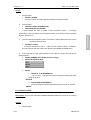
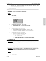
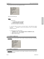
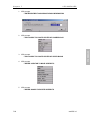
2.The user would either select the name of a previously saved file or enter the name of
a new file in the Dialogue window. The recommended practice is to add the
extension .vpg to a newly created file.
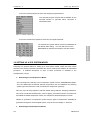
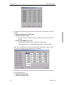
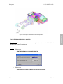
3.If creating a NEW file, the user would be prompted to do so:
Figure 3.1.2 Create New File Prompt
3-7
eta/VPG3.0
GETTING STARTED
appropriate for their operating system. In Windows this may be accomplished by double
Chapter 3
G e t t i n g Sta r t e d
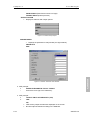
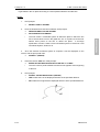
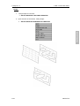
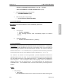
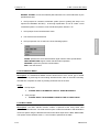
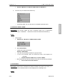
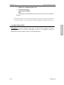
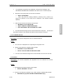
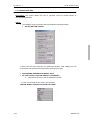
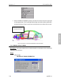
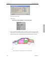
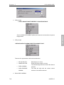
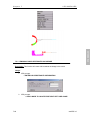
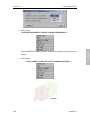
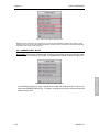
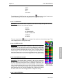
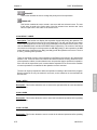
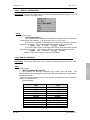
4.The user will be prompted to select the analysis program desired:
The analysis program selected will set defaults for the
eta/VPG session to generate either LS-DYNA or
NASTRAN cards.
Figure 3.1.3 Select Analysis Type
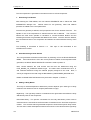
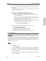
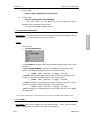
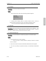
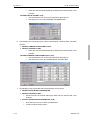
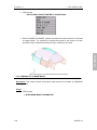
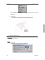
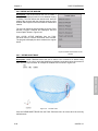
5.The user will also be prompted to select the Unit System desired:
the default value setting. The user will now be in the
MAIN MENU of eta/VPG and ready to start the session.
Figure 3.1.4 Unit System
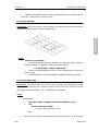
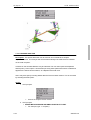
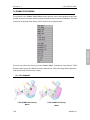
3.2 SETTING UP A VPG SYSTEM MODEL
Following is a general outline for setting up a VPG system model. There are three unique
modules in the VPG pre-processor that allow the user to create a VPG model in an automated
procedure.
A detailed description of each of these processes is available in the
VPG/Structure Tutorial.
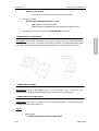
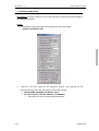
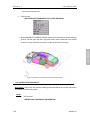
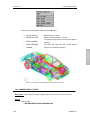
1- Generating a Front Suspension Model
The user begins by selecting a front suspension model from the SUSPENSION MENU.
The user determines the desired optional components such as stabilizers and steering
system types and enters the node coordinates for suspension geometry.
Next, the user will be prompted to edit the default spring stiffness, damping coefficients,
extra node coordinates, default mass, center of gravity, and inertia moment. Once the user
has edited the default suspension values, the suspension will be displayed on screen.
Details on generation of suspension models and the types of suspensions available for
generation through the VPG template system, may be found in Chapter 7, Section 2.
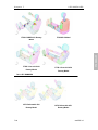
2- Generating a Rear Suspension Model
3-8
eta/VPG3.0
GETTING STARTED
The selected unit system will be stored in the database as
Chapter 3
G e t t i n g Sta r t e d
The rear suspension is generated in the same manner as a front suspension.
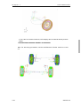
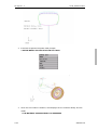
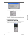
3- Generating Tire Models
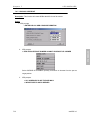
After entering the TIRE MENU, the user selects GENERATE and is offered the TIRE
PARAMETER dialogue box.
Default values for tire geometry, mass and inflation
pressure are edited to the user's parameters.
Once the tire geometry is defined, VPG prompts the user for the location of the tire. The
spindle of one of the suspensions is selected and the tire is attached.
The user then
selects the other three spindles in clockwise or counter-clockwise fashion and the
remaining three tires are generated and added to the model. Once the tires are defined,
the user attaches them to the suspension and defines the initial rotational velocity of the
Tire modeling is discussed in Section 7.3.
This topic is also described in the
VPG/Structure Tutorial.
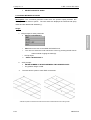
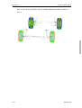
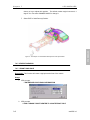
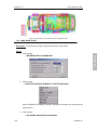
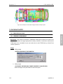
4- Auto-Generating a Road Surface
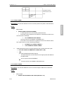
The user generates the desired road surface by selecting it from the ROAD SURFACE
MENU. If the road surface is not in the correct position in relation to the suspension after
generation, the MOVE ROAD SURFACE command is used to position it.
Next, contact between the road surface and the tires are determined using the
FIVE_NODES_TO_SURFACE interface type. The road is then constrained in the Y, Z,
and rotational directions using the material property assigned to the road.
Next, a
velocity is assigned to the road using the BOUNDARY_PRESCRIBED_MOTION card.
Details on ROAD SURFACE libraries may be found in Chapter 7, Section 1.
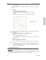
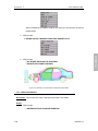
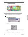
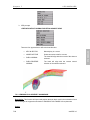
5- Adding a Body Model
The body to chassis/suspension attachment process depends upon what type of body
model the user wishes to use for analysis (deformable or rigid).
Rigid Body - The rigid body model is constrained to the rigid beams that define the body
attachment points on the suspension.
Deformable Body - The specific coordinates for the body attachment points must be
entered when the user defines the Extra Node Coordinates for the front/rear suspension
models. This ensures that the generated suspension would fit the specific body model.
The user then creates weld spiders between the mounts on the vehicle and the rigid body
3-9
eta/VPG3.0
GETTING STARTED
tires.
Chapter 3
G e t t i n g Sta r t e d
beams on the suspension. Next the user defines the BODY_LOAD_DEFINITION_CARD
to define the gravity.
After defining the gravity, the user pre-loads the suspension using the ELEMENT
DEFINITION CARD.
6- Defining VPG Analysis Control Parameters
First, the CONTROL ENERGY and CONTROL TERMINATION cards must be defined.
Next, the output control interval data for the ASCII database must be determined. Then
the BINARY DATABASE cards must be edited to control the output interval of the results
and restarts.
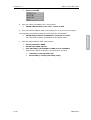
From the ANALYSIS menu, select DYNA INPUT FILE OPTIONS, edit the dialogue box, and
submit the analysis. For additional information, please see Section 8.11.
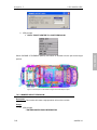
8- Displaying Results
Enter the POST PROCESSING menu and select D3PLOT (LS-DYNA result file). Then
select the analysis' 'd3plot' from the File Menu. Select LS-DYNA version 970. Select
ALL AVAILABLE STEPS. Select ALL COMPONENTS.
The results from each of the analysis steps will then be read into eta/VPG. A binary result
file will be created at this time (named 'd3plot.pp'). Since the results are not saved to the
eta/VPG database, this binary file should be reread into the post-processing menu when
the user wishes to view the results again. This file is read much faster than the d3plot files.
The results are now ready to be post processed using a variety of features.
9- Graph Plotting
To graph the results, select GRAPH from the Main Menu. The user then has the option
of reading in a previously saved LS-DYNA ASCII graph file. When exiting the GRAPH
MENU, the user has an option to save the graphs in a binary file for future processing.
This file will be loaded mush faster than the LS-DYNA ASCII files.
3-10
eta/VPG3.0
GETTING STARTED
7- Analysis Submission
Chapter 4
Main Menu
4
Chapter
Chapter 4: Main Menu
This is the first menu bar the user encounters when beginning a session with VPG. The initial
options unfold into an additional series of submenus. These submenus are documented in
the following sections.
Menus are selected by mouse pick and contain all eta/VPG functions. Each of these menus
may be accessed through the Function Keys.
The FILE menu allows for the import and export of data into and out of the eta/VPG database.
This data may be in the form of finite element data, CAD files, or a combination of the two.
The FILE menu also allows users to SAVE databases. It is important to know that eta/VPG
does not automatically save the user’s data. The user must execute the SAVE command to
write the database changes to the file.
The FILE menu provides functions for RESTART , IMPORT and EXPORT functions.
4.2 PARTS
Models constructed in eta/VPG are organized into PARTS. These Parts may contain lines,
surfaces, and/or elements. Parts may contain only one type of entity or may contain any
combination of entity types. Parts may be created from the PART menu.
All data that is created in eta/VPG, such as elements, lines, or surfaces, is created in the
CURRENT PART. The current part may be selected or changed from the PART menu. Once
selected, all data created is placed in this part.
Parts may be turned on and off for display purposes from the PART menu.
4-1
eta/VPG 3.0
MAIN MENU
4.1 FILE
Chapter 4
Main Menu
4.3 PRE
The PRE menu is the main Preprocessing menu. In this menu, the user will find all of the
necessary modeling functions to create elements, nodes, materials, contacts, element
properties, and boundary conditions.
4.4 ROAD
The ROAD Menu allows users to select and place a road surface model in their VPG model.
This menu is only available if the user is in LS-DYNA mode (see UTILITIES menu, SETUP
command).
4.5 SUSPENSION
The SUSPENSION menu allows users to create suspension system models from predefined
templates. This menu is available only in LS-DYNA mode (see UTILITIES menu). Typical
automotive suspension types are predefined, and users may input their data into the desired
suspension template. VPG will then construct an LS-DYNA-based model using appropriate
entities for the various model components.
4.6 TIRE
Chapter 7. This menu is available only in LS-DYNA mode (see UTILITIES menu).
4.7 SAFETY
This menu accesses the VPG/Safety Module. Access to this menu is available only in
LS-DYNA mode (see UTILITIES menu).
4.8 ANALYSIS
The ANALYSIS menu allows users to define all parameters necessary to execute an analysis.
Many non-graphical parameters are required to carry out an analysis. For instance, LS-DYNA
models require a termination time and require a definition of output frequency for the model
results. VPG allows users to access all CONTROL CARDS and DATABASE parameters
available in LS-DYNA. Similar capabilities are available for NASTRAN, RADIOSS and
PAMCRASH model databases.
4.9 FATIGUE
The FATIGUE menu allows users to post process stress data calculate fatigue damage for
LS-DYNA or NASTRAN data. This menu allows users to calculate and display the results of
4-2
eta/VPG 3.0
MAIN MENU
VPG contains tools to generate parametric tire models. These tire models are described in
Chapter 4
Main Menu
this fatigue calculation. Additional information may be found in Chapter 7.
4.10 POST
The POST menu launches the ETA Postprocessor application. By selecting this menu option,
the current database is stored in a temporary location and closed. The Post Processor
application is then opened. Once the Postprocessor application is closed, the temporary
database is then restored.
4.11 GRAPH
Certain analysis result data may be displayed in a graphical format using curves. The plotting
and control of these graphs is accessed through this menu selection.
4.12 UTILITIES
The UTILITIES menu allows users to perform various modeling and display functions. As an
example, the user may add Arrows or Comments on the screen for additional information
when creating JPEG or GIF image files.
An important feature of the UTILITIES menu is the SETUP command. This command allows
the user to specify display and model database characteristics. From this menu the user may
On the SETUP menu, the user may specify the analysis program for the current database.
This function defines the menus that will be displayed, as well as the content of those menus.
As an example, when the NASTRAN option is selected for this command, the menus will then
contain the material types, element types, and boundary conditions that pertain to NASTRAN
models. All analysis parameters will also be specified in a manner consistent with NASTRAN.
If the user selects LS-DYNA, similarly, all menus, material models, contact types, and element
types will be consistent with LS-DYNA models.
4.13 VIEW
This menu allows users to manipulate the model in the Display Window. Views may be saved
and recalled by the user.
4.14 HELP
The HELP menu allow user to identify the build date and version of the VPG software. The
HELP menu provides access to the on-line version of this documentation, in a searchable
format. Contains online help and access to these Manuals.
4-3
eta/VPG 3.0
MAIN MENU
specify the model type and global parameters to be applied to the model.
Chapter 5
File Manager
5
Chapter
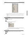
Chapter 5: File Manager
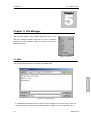
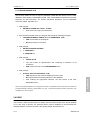
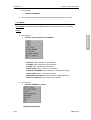
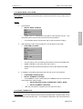
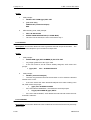
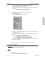
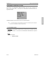
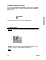
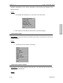
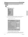
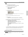
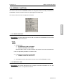
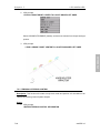
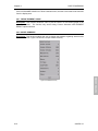
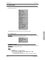
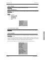
The options available in FILE MENU allow the user to input
data from different analysis programs into VPG. A detailed
description of each function in the FILE menu is given in the
following sections.
Figure 5.1 File Menu
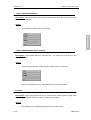
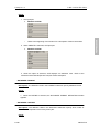
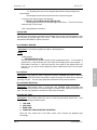
5.1 NEW
FILE MANAGER
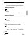
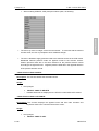
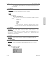
This function allows the user to create a new database file.
Figure 5.1.1 New File Window
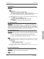
If a database file already has been opened in VPG and has not been saved yet, there is a
warning message for saving the opened file before creating a new one. See Figure 5.1.2.
5-1
eta/VPG 3.0
Chapter 5
File Manager
Figure 5.1.2 Save Prompt
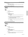
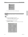
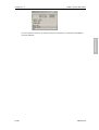
5.2 OPEN
This function allows the user to open databases.
Figure 5.2.1 Open File Window
If a database file already has been opened in VPG and has not been saved yet, there is a
FILE MANAGER
warning message for saving the opened file before opening another one. See Figure 5.2.2.
Figure 5.2.2 Save Prompt
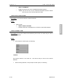
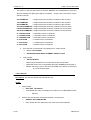
5.3 RESTART
This function allows the user to restart the current database from the last saved point. VPG will
prompt the user to save the current file. See Figure 5.2.2.
After that, VPG will prompt the user to restart from a new database or the current one.
5-2
eta/VPG 3.0
Chapter 5
File Manager
Figure 5.3.1 Restart Database
-
Select YES to open a new database. The Open File Window appears.
-
Select NO to reopen the current database from the last saved point
-
ABORT to cancel the operation
5.4 SAVE
This function updates the current database. The User may overwrite the existing file or create
a new file at the execution of the SAVE command. If the user chooses to overwrite the file all
previous mode data will be overwritten and the current model configuration will be saved. If the
user chooses to create a new file, the current database will not be updated and the current
model configuration will be written to a new file, with the database name provided by the user.
This file now becomes the current model database open in VPG.
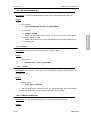
5.5 SAVE AS
FILE MANAGER
This function saves the current database as a new file. See Figure 5.5.1
Figure 5.5.1 Save Database As
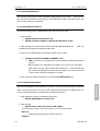
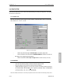
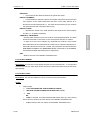
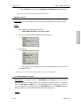
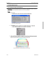
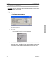
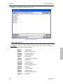
5.6 IMPORT
This function allows the user to read CAD or model data (See Figure 5.6.1).
5-3
eta/VPG 3.0
Chapter 5
File Manager
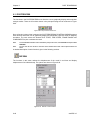
Figure 5.6.1 Import File Window
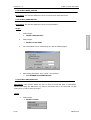
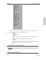
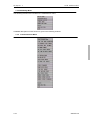
5.6.1 FILE TYPE
Select the drop down selection in the FILE TYPE field to select the proper format. The
available formats are:
MODEL DATA FORMAT: LS-DYNA, Nastran, Abaqus, Genesis, Moldflow, PamCrash,
Radioss
CAD DATA FILE: IGES, LINE, VDA, DXF, CATIA, STEP, Unigraphics
SPECIAL MODEL FORMAT: ADAMS, ADAMS-Pre
FILE MANAGER
A detailed description of each file import function is given in the following section
5-4
eta/VPG 3.0
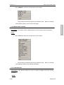
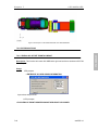
Chapter 5
File Manager
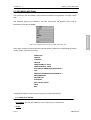
Figure 5.6.2 File Format
5.6.1.1 READ CAD DATA
A series of functions in this menu allows the user to read converted wireframe and surface
data into VPG. The supported file formats include:
IGES (*.igs, *.iges), VPG (*.lin), VDA (*.vda), DXF (*.dxf), CATIA4 (*.model), CATIA5
(*.catpart), STEP (*stp,*.step), and UG (*.prt)
In order to provide flexibility in accepting line data from different CAD systems, VPG uses a
neutral line data format to communicate with these CAD systems: IGES, PDGS standard,
CGS (INCA and DES), DXF, etc. Once the user has entered the command, the files with the
appropriate suffix will be listed in the options area. The user can then select the desired
5.6.1.2 READ ABAQUS FILE
VPG reads ABAQUS files directly with its built in translator. The VPG ABAQUS file
extension is .inp.
5.6.1.3 READ DYNA FILE
This function allows the user to read both keyword and non-keyword LS-DYNA (.dyn) files
directly into VPG. VPG supports versions 88 to 970 Keyword. Once the user has entered
the command, the files with the suffix .dyn will be listed in the VPG FILE WINDOW. The
user can then select the desired file.
5-5
eta/VPG 3.0
FILE MANAGER
file.
Chapter 5
File Manager
5.6.1.4 READ GENESIS FILE
This function allows users to read GENESIS (.dat) files directly into VPG.
Once the user
has entered the command, the files with the suffix .dat will be listed in the options area. The
user can then select the desired file.
5.6.1.5 READ MOLDFLOW FILE
This function allows users to read MOLDFLOW data directly into VPG.
1. VPG prompts:
>
READING MOLDFLOW INPUT FILE
>
ENTER THE ROOT NAME OF THE MOLDFLOW INPUT FILES
2. After entering the root file name (assuming that the .mfl, .mod, and .tri
files are
available) VPG displays the MOLDFLOW model.
3. If the user is reading data into an existing model, VPG prompts:
>
OFFSET NODE AND ELEMENT NUMBERS. (Y/N)
•
YES renumbers the new data at the lowest available unused node/element
number.
•
NO compares the node/element numbers and ignores the duplicates -VPG retains only the original nodes and elements (i.e., if the MOLDFLOW
file contains all duplicate node and element numbers, the new part will read
in with out the presence of elements or nodes).
4. VPG reads in the file and returns the user to the FILE MANAGER menu.
VPG uses NASTRAN as a file translator so that the user may import and export models and
mesh. This function allows the user to read a NASTRAN bulk data file (.dat) directly into
VPG. All existing properties, materials, and subcases are retained.
1. VPG displays the VPG FILE MENU and prompts:
>
DEFINE NASTRAN BULK DATA FILE
2. VPG prompts:
>
SELECT PART CONTROL OPTION FOR CBARS
The files with the suffix .nas will be listed for you in the options area.
MAT1 ID
•
CBARS will be grouped by common MAT1 ID.
PBAR ID
5-6
eta/VPG 3.0
FILE MANAGER
5.6.1.6 READ NASTRAN BULK
Chapter 5
File Manager
•
CBARS will be grouped by common PBAR ID.
PART NAME
•
CBARS will be grouped by their individual part names.
3. If the user is reading data into an existing model, VPG prompts:
>
OFFSET NODE AND ELEMENT NUMBERS. (Y/N)
•
YES renumbers the new data at the lowest available unused node/element
number.
•
NO compares the node/element numbers and ignores the duplicates—VPG
retains the only original nodes and elements (i.e., if the NASTRAN file
contains all duplicate node and element numbers, the new part will read in
without the presence of elements or nodes).
4. VPG reads in the file and returns the user to the FILE MANAGER menu.
5.6.1.7 READ PAMCRASH FILE
This function allows the user to read a PAMCRASH (.pc) file directly into VPG. Once the
user has entered the command, the files with the suffix .pc will be listed in the options area.
The user may then select the desired file.
5.6.1.8 READ RADIOSS FILE
This function allows the user to read a RADIOSS data file directly into VPG. VPG can read
fixed format input files from RADIOSS Versions 2.1, 2.2, 2.3, 3.1, and 4.1. VPG can write
RADIOSS 4.1 fixed format input files. VPG supports all input cards of RADIOSS 4.1 fixed
format. VPG contains options when reading RADIOSS input and output files. These options
relate to the translation of rigid bodies to VPG and the loading of model information.
RADIOSS requires two files to be loaded- one is the RADIOSS output file (.out), which
contains model information. If the user has both files, he should click YES at the first
prompt to read both the RADIOSS output and input files.
If the user has only the
RADIOSS input file, the user should select NO.
1. Begin with reading the RADIOSS output file (.out). This loads the rigid body
information. VPG will prompt:
>
ADJUST RIGID BODY PRIMARY NODES FROM RADIOSS
OUTPUT. (Y/N)
•
If YES is selected, the RIGID BODY information will be loaded with the
output file. The user can then load the RADIOSS input file (.D00).
•
If NO is selected, VPG will prompt:
>ADJUST RIGID BODY PRIMARY NODES BY VPG. (Y/N)
5-7
eta/VPG 3.0
FILE MANAGER
contains the rigid body information. The second is the RADIOSS input file (.D00), which
Chapter 5
File Manager
•
YES will locate the RIGID bodies and recalculate the rigid body primary
node locations.
•
NO will finish the input sequence without modifying the model information.
VPG creates some default materials and element properties for elements that are lost
during the file reading. These are assigned to the part DEFAU_#.
VPG creates a node
set, element set, material set, property set, and interface (contact) set for boundary
conditions, interface, rigid walls, time history etc. VPG can read multiple RADIOSS input
files into the same database.
5.6.1.9 READ SUSP (ADAMS)
Section J of the Appendix gives a complete description of converting ADAMS models to
VPG. Please refer to that section when converting an ADAMS suspension.
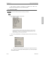
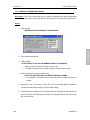
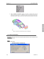
5.7 EXPORT
This function allows the user to output from the current database. The options are similar to the
FILE MANAGER
options mentioned above. See Figure 5.7.1.
Figure 5.7.1 Export file Window
A detailed description of each file export function is given in the following section
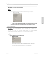
5.7.1 WRITE ABAQUS FILE
VPG displays the CONTROL PARAMETER window. Users may select the parameters
with the mouse button and enter new values through the keyboard. (The parameters are
5-8
eta/VPG 3.0
Chapter 5
File Manager
ABAQUS specific. Refer to the ABAQUS manual for more details.)
1. VPG prompts:
>
ENTER FILE NAME OR "STOP" TO EXIT
•
Enter a file name (up to 24 characters). Using the .inp convention for
ABAQUS files is suggested.
2. If the file name already exists, VPG prompts the following message:
>FILENAME ALREADY EXISTS, O.K. TO OVERWRITE. (Y/N)
•
YES will overwrite the existing file.
•
NO will prompt for a file name.
3. If materials and properties have already been defined, a "CONTROL PARAMETERS" window will be shown and VPG prompts:
>
DEFINE/MODIFY DATA
>
SELECT AN ITEM TO EDIT
•
EXIT sends user to step 6.
4. If there are no materials or properties defined in the database, VPG prompts:
>
NO MATERIALS DEFINED IN DATABASE! SELECT OPTION
?
1 - SELECT GLOBAL DEFAULT
•
Defines one global material and one global property for the database.
2 - DEFINE BY PARTS
•
Assigns materials and properties to each individual part.
3 - IGNORE DEFINITION
•
Ignores material and property definition.
4 - EXIT
>
OUTPUT ONLY ACTIVE PARTS. (Y/N)
•
YES will only output the active parts (parts that are turned ON).
•
NO will output all parts in the database.
FILE MANAGER
5. VPG prompts:
6. VPG prompts:
>
ENTER TITLE
•
The user can enter up to 60 characters.
5.7.2 WRITE BINARY FILE
This function allows the user to output a binary model file from current model data. The
binary model file may be used to combine finite element models from different VPG data
files. This function will output elements and nodes only.
5-9
eta/VPG 3.0
Chapter 5
File Manager
1. VPG prompts:
>
ENTER FILE NAME OR "STOP" TO EXIT
•
Enter a file name (up to 24 characters). Using the .bin convention for
BINARY files is suggested.
2. If the file name already exists, the program will prompt the following message:
>
FILENAME ALREADY EXISTS, O.K. TO OVERWRITE. (Y/N)
•
YES will overwrite the existing file.
•
NO will prompt for a file name.
3. VPG prompts:
>
OUTPUT ONLY ACTIVE PARTS. (Y/N)
•
YES will only output the elements displayed on the screen.
•
NO will output all elements existing in the database.
4. VPG returns the user to the FILE MANAGER menu.
5.7.3 WRITE C-MOLD FILE
This function allows the user to output a C-MOLD (.fem) file from current model data.
1. VPG prompts:
>
WRITING C-MOLD INPUT FILE
SELECT UNIT CURRENTLY USED IN DATABASE
•
MM
CM
METER
IN
EXIT
>
SI UNIT WILL BE USED IN THE FEM FILE, SCALE FACTOR =
X.XXXXXX
>
ENTER FILE NAME OR "STOP" TO EXIT
3. If there are no materials or properties defined in the database, VPG prompts:
>NO PROPERTIES DEFINED IN DATABASE! SELECT OPTION
?
1 - SELECT GLOBAL DEFAULT
•
Defines one global material and one global property for the database.
2 - DEFINE BY PARTS
•
Assigns materials and properties to each individual part.
3 - IGNORE DEFINITION
•
Ignores material and property definition.
4 - EXIT
5-10
eta/VPG 3.0
FILE MANAGER
2. VPG echoes the user's unit selection and prompts for the new file's name:
Chapter 5
File Manager
4. VPG prompts:
>
OUTPUT ONLY ACTIVE PARTS. (Y/N)
•
YES will only output the active parts (parts that are turned ON).
•
NO will output all parts in the database.
5. VPG prompts:
>ENTER TITLE
•
The user can enter up to 60 characters.
6. If there are no model properties defined in the database, VPG prompts:
>
NO NODAL PROPERTIES DEFINED IN DATABASE
>
ENTER NEW PROPERTY NAME OR "EX" TO EXIT
•
A "NODAL PROPERTY" window appears after a name is selected, and
VPG prompts the user to modify data in the window.
•
EXIT ends this function and returns the user to the FILE MANAGER menu.
5.7.4 WRITE DYNA FILE
This function allows the user to output an LS-DYNA data deck directly from the VPG
database.
1. VPG prompts:
>
ENTER FILE NAME OR "STOP" TO EXIT
•
Enter a file name (up to 24 characters). The .dyn extension is suggested
for LS-DYNA files.
2. If the file name already exists, the program will prompt the following message:
FILE NAME ALREADY EXISTS, O.K. TO OVERWRITE. (Y/N)
•
YES will overwrite the existing file.
•
NO will prompt for a file name.
FILE MANAGER
>
3. VPG displays the current unit system and prompts:
4
Figure 5.7.2 Unit System Menu
.
VPG prompts:
5-11
eta/VPG 3.0
Chapter 5
>
File Manager
OUTPUT ONLY ACTIVE PARTS. (Y/N)
•
YES will only output the elements displayed on the screen.
•
NO will output all elements existing in the database.
5. VPG prompts:
>
ENTER TITLE
6. After entering the title, VPG displays the CONTROL TERMINATION CARD if a
termination time has not been specified yet. Once the card is defined and the user
selects OK, the DYNA deck is written.
Note: If the properties/materials are not assigned to the parts in the database, VPG prompts the user to
define the properties/materials by default, by global default, or by part.
5.7.5 WRITE GENESIS FILE
This function allows the user to output a GENESIS (.dat) data deck directly from the VPG
database.
5.7.6 WRITE LINE DATA FILE
This function allows the user to output a LINE/SURFACE DATA (.lin) data file directly from
the VPG database.
1. VPG prompts:
ENTER FILE NAME OR "STOP" TO EXIT
•
Enter a file name (up to 24 characters). The .lin extension is suggested.
2. If the file name already exists, the program will prompt the following message:
>
FILENAME ALREADY EXISTS, O.K. TO OVERWRITE. (Y/N)
?
YES
NO
•
YES will overwrite the existing file.
•
NO will prompt for a file name.
3. VPG prompts:
>
WRITE LINES/SURFACES ONLY IN ACTIVE PARTS. (Y/N)
?
YES
NO
5-12
•
YES will only output the lines/surfaces displayed on the screen.
•
NO will output all elements’ lines/surfaces in the database.
eta/VPG 3.0
FILE MANAGER
>
Chapter 5
File Manager
5.7.7 WRITE MOLDFLOW FILE
This function allows the user to output the current model data into an external file in
MOLDFLOW format. VPG supports Moldflow version 5.1.
Note: Node and element numbers must be in sequence to write a MOLDFLOW file. The user may either
renumber or compress nodes/elements (see NODE OPTIONS menu). If the nodes are not in sequential
order, VPG prompts:
>
RENUMBER NODE NUMBERS AND TRY AGAIN (or)
>
RENUMBER ELEMENT NUMBERS AND TRY AGAIN
1. VPG prompts:
>
ENTER ROOT NAME FOR INPUT FILES OR STOP TO EXIT
•
VPG writes three files in accordance with the MOLDFLOW format
(.mfl, .mod, and .tri).
2. If the file name already exists, the program will prompt the following message:
>FILENAME ALREADY EXISTS, O.K. TO OVERWRITE. (Y/N)
•
YES will overwrite the existing file.
•
NO will prompt for a file name.
3. After entering file name, VPG prompts:
>
SELECT UNIT CURRENTLY USED IN DATABASE
?
MM
CM
IN
>
FILE MANAGER
4. VPG prompts:
OUTPUT ONLY ACTIVE PARTS. (Y/N)
•
YES will only output the elements displayed on the screen.
•
NO will output all elements existing in the database.
5. VPG prompts:
>
ENTER TITLE
5.7.8 WRITE NASTRAN
This function allows the user to output the current model data to an external file into
NASTRAN format. The user may output either the complete model data or partial model
data. For detailed descriptions of these options, users should refer to NASTRAN software
documentation.
5-13
eta/VPG 3.0
Chapter 5
File Manager
Figure 5.7.3 Nastran File Options
Detailed description:
1. VPG Prompts:
>
ENTER CONTROLS OPTION
ANALYSIS TYPE
Displays a submenu with NASTRAN analysis types:
FILE MANAGER
•
Figure 5.7.4 Nastran analysis type
FORMAT OPTION
•
Displays a submenu with file format options:
Figure 5.7.5 Nastran Format Option
5-14
eta/VPG 3.0
Chapter 5
File Manager
SINGLE FIELD (fixed format columns of eight)
DOUBLE FIELD (double precision)
OUTPUT OPTION
•
Displays a submenu with output options:
Figure 5.7.6 Nastran Output Option
PARAM CARDS
•
Displays the parameter modify window (see figure below).
WRITE FILE
FILE MANAGER
EXIT
Figure 5.7.7 Nastran Parameter Card Window
2. VPG prompts:
>
ENTER FILE NAME OR "STOP" TO EXIT
•
Enter a file name (up to 24 characters).
3. VPG prompts:
>
OUTPUT ONLY ACTIVE PARTS. (Y/N)
?
YES
NO
5-15
•
YES will only output the elements displayed on the screen.
•
NO will output all elements existing in the database.
eta/VPG 3.0
Chapter 5
File Manager
4. VPG prompts:
>
ENTER ANALYSIS TITLE
•
Any alphanumeric input up to 72 characters may be entered as the title of
the NASTRAN bulk data file.
5.7.9 WRITE PAMCRASH FILE
This function allows the user to output a PAMCRASH (.pc) data file directly from the VPG
database.
1. VPG prompts:
>
ENTER FILE NAME OR "STOP" TO EXIT
•
Enter a file name (up to 24 characters).
2. If the file name already exists, the program will prompt the following message:
>
FILENAME ALREADY EXISTS, O.K. TO OVERWRITE. (Y/N)
•
YES will overwrite the existing file.
•
NO will prompt for a file name.
3. VPG prompts:
>
SELECT PAMCRASH VERSION:
?
1 - SEQUENTIAL
2 - FREE NUMBERING
>
DO YOU WANT TO USE KEYWORD INPUT (Y/N)
?
YES / NO
>
OUTPUT ONLY ACTIVE PARTS. (Y/N)
?
YES / NO
5. VPG prompts for optional keyword cards via pop ups.
6. VPG prompts:
>
ENTER TITLE
•
The user enters an alphanumeric title containing a maximum of 48
characters.
•
VPG returns the user to the FILE MANAGER menu.
Note: If the properties/materials are not assigned to the parts in the database, VPG prompts the user to define the
properties/materials by default, by global default, or by part. Supported properties are listed in Appendix A, VPG
Capabilities for F.E.A. Programs.
5-16
eta/VPG 3.0
FILE MANAGER
4. VPG prompts:
Chapter 5
File Manager
5.7.10 WRITE RADIOSS FILE
This function allows the user to output a RADIOSS (.rad) data file directly from the VPG
database. When writing a RADIOSS input file, VPG creates default materials and element
properties for some elements. For specific translation properties, see the RADIOSS
conversion tables, Appendix D, H.
1. VPG prompts:
>
ENTER FILE NAME OR "STOP" TO EXIT
•
Enter a file name (up to 24 characters).
2. If the file name already exists, the program will prompt the following message:
>
FILENAME ALREADY EXISTS, O.K. TO OVERWRITE. (Y/N)
•
YES will overwrite the existing file.
•
NO will prompt for a file name.
3. VPG prompts:
>
SELECT RADIOSS VERSION
?
1 - VERSION 2.2
2 - VERSION 2.3
4. VPG prompts:
>
ENTER TITLE
•
The user enters an alphanumeric title containing a maximum of 48
characters.
•
VPG returns the user to the FILE MANAGER menu.
5. VPG prompts:
OUTPUT ONLY ACTIVE PARTS. (Y/N)
•
YES outputs only the elements displayed on the screen.
•
NO outputs all of the existing elements in the database.
•
After entering the appropriate selection, the user returns to the FILE
MANAGER menu.
Note: If the properties/materials are not assigned to the parts in the database, VPG prompts the user to define the
properties/materials by default, by global default, or by part. Supported properties are listed in Appendix A, VPG
Capabilities for F.E.A. Programs.
5.8 PRINT
This function creates a postscript file of display area and sends the file to the printer (default)
or to a file. Prior to printing, the postscript driver must be initialized to accommodate the
eta/VPG software. The user can define the printing default. See Section 5.9.
5-17
eta/VPG 3.0
FILE MANAGER
>
Chapter 5
File Manager
5.9 PRINT SETUP
This function allows the user to define the default setting for printing of image files. The options
are shown in Figure 5.9.1.
5.9.1 PAPER CUT
The user can specify a given paper size and margin. Standard paper sizes are supported,
such as 8.5”x11”, 11”x17”, A4, etc.
-
Select drop list at the right of PAPER CUT to choose a paper size.
-
Enter a number in the field beside PAPER MARGIN to define the shorter of
the paper’s two margins (top and bottom).
Select the button beside Paper Length Unit to choose a unit (in or mm).
-
5.9.2 PRINTER
-
The user can select a printer or select a format to print to a file
-
Enter the printer name in field or select from the list below
-
If Print To File is toggled on, the user can choose a format by selecting the drop
list beside Print File Format. VPG supports postscript (PS), encapsulated
postscript (EPS), .GIF, and .JPG file formats.
Note: When PRINT is selected, the user will be prompted enter a file name instead of the File being directly sent to
5-18
eta/VPG 3.0
FILE MANAGER
Figure 5.9.1 Printer Setup
Chapter 5
File Manager
the printer
5.9.3 ORIENTATION
This function sets the page orientation as landscape or portrait.
5.9.4 COLOR TYPE
Select the drop list beside Color Type to select a color type.
5.9.5 POSTSCRIPT
There are two levels. Level 2 is the default setting. Level 1 should be selected when using
an older model PostScript printer.
5.9.6 RUN LENGTH ENCODE
This option reduces the Postscript file size. Usually the reductions are dramatic (for PS
Level 1, this is automatically turned off).
5.9.7 ASCII85 ENCODE
This option reduces the Postscript file size. Usually the reductions are dramatic (for PS
Level 1, this is automatically turned off).
5.9.8 BINDING OPTION
This function leaves binding space along the top or left margins of the print and selects
non-Binding space.
This function reverses the black and white colors image in some cases. This feature affects
only the background of the image.
5.9.10 BOUNDING BOX
This function draws a line frame around picture’s border.
5.9.11 TIME STAMP
This function prints the current time at the lower right corner of the picture file.
5-19
eta/VPG 3.0
FILE MANAGER
5.9.9 REVERSE VIDEO
Chapter 5
File Manager
5.9.12 FILE NAME
This function prints the file name at the lower right corner of the picture.
5.9.13 eta/VPG
This function prints eta/VPG logo at the lower left corner of the picture.
5.9.14 SELECT REGION
This function allows the user to define a graphic region by using a drawing window. Only the
graphics within the region will be written to the graphics file. If the option is off (default), the
complete graphics region will be saved to the output file.
Note: The user will be prompted to define the region (drag window) after PRINT is selected
5.9.15 NO.OF COPIES
This function allows the user to print multiple copies.
5.9.16 SETUP SAVE/LOAD
Default page settings may be used, saved, and selected by the user. All parameters are
defined in the HARDCOPYDEFAULT file in the VPG installation directory.
5.9.16.1 LOAD SYSTEM DEFAULT
This function will load the system defaults that are saved in a VPG Hardcopy Default file
located in the VPG executable directory.
This function will load the user-defined defaults that have been saved in a HardcopyDefault
file located in the user’s home directory.
5.9.16.3 SAVE AS DEFAULT
This function saves user-modified hardcopy options to a HardcopyDefault file located in the
user’s Home directory.
5.10 EXIT
This function allows the user to exit the program. VPG will prompt to save current database.
5-20
eta/VPG 3.0
FILE MANAGER
5.9.16.2 LOAD USER DEFAULT
Chapter 6
PRE-PROCESSOR
6
Chapter
The Pre Processor menu contains a series of submenus with the ability to create and edit lines,
surfaces, elements, material properties, and element properties.
The Pre Processor submenus are described in their own individual sections that follow.
Note: DYNA MISC only appears when the analysis code is set to LS-DYNA. SUPERELEMENT only
appears when the analysis code is set to NASTRAN.
6-1
eta/VPG3.0
PRE-PROCESSOR
CHAPTER 6: PRE PROCESSOR
Chapter 6
PRE-PROCESSOR
6.1 LINE
The functions of the LINE MENU are intended to create a new set of line data or to modify
existing line data. VPG currently has a limitation of 150,000 lines or 200,000 points per
PRE-PROCESSOR
database. The following options are available in the LINE MENU:
Each option is selectable by using the left mouse button to select the menu item or by typing
the first two letters of each command in the prompt in the VPG Message Window. A detailed
description of each function is given in the following sections.
6.1.1 ADD POINTS
Description: This function allows the user to add points to an existing line either randomly or
between two selected points.
Usage:
1.
VPG prompts:
>
2.
VPG prompts:
>
6-2
SELECT LINE FOR ADDED POINTS
SELECT POINT LOCATION ON LINE
eta/VPG3.0
Chapter 6
PRE-PROCESSOR
•
The user may create new points by placing the cursor anywhere on the line
and pressing the left mouse button, or the user may select one the following
options:
BETWEEN 2 POINTS
•
This option allows the user to select 2 end points of a line
segment and create a specified number of new points between the them
(see step 3).
CURSOR LOCATION
POINT
REJECT LAST
VPG prompts:
>
BETWEEN 2 POINTS
>
SELECT POINT 1 ON LINE
>
SELECT POINT 2 ON LINE
>
ENTER NUMBER OF POINTS TO BE ADDED
•
4.
PRE-PROCESSOR
3.
The user enters the desired number of points.
EXIT or DONE returns the user to the LINE menu.
Circles indicate the locations where points have been added.
6.1.2 GENERATE ARCS
Description: This function allows the user to generate arcs and circles either globally, locally,
or about a selected node or point. The created arc will be included in the CURRENT PART
(see PART CONTROL MENU).
Usage:
1.
6-3
VPG prompts:
>
CREATE LOCAL COORDINATES
>
PICK NODE/PT FOR ORIGIN
eta/VPG3.0
Chapter 6
PRE-PROCESSOR
•
VPG is asking for a desired coordinate system (local or global) about which
to create the arc. VPG prompts the user to create a local system. A thorough
explanation of how to create a local coordinate system is covered in the Local
Coordinate System, Section 2.15.
Note: Arcs and circles are generated about the local W-axis or global Z-axis.
2.
Once the desired coordinate system is acquired, it will be displayed on the
screen and the prompt will read:
>
If accepted, VPG prompts:
PRE-PROCESSOR
3.
ACCEPT? (Y/N/A)
>
ENTER RAD, TH1, TH2, INC
•
RAD = radius of arc.
•
TH1 = beginning point of arc or circle.
•
TH2 = ending point of arc or circle.
•
INC = angle increment between points (default is 5 degrees).
•
Any real value greater than zero is valid. i.e., 100,0,360,10 is a circle with a
radius of 100 units with an increment of 10 degrees between points.
An arc and a circle have been generated with the same center.
4.VPG prompts:
>
SAME CENTER AND PLANE? (YES/NO/EXIT)
•
Do you want to create another circle/arc using the same center and plane.
•
YES returns the user to step 3.
NO returns the user to step 1.
EXIT exits the function.
6.1.3 ARC TANGENT 2 LINES
6-4
eta/VPG3.0
Chapter 6
PRE-PROCESSOR
Description: This command allows the user to create an arc tangent to 2 lines. The arc
will be included in the CURRENT PART (see PART CONTROL MENU). The tangent arc
will trim the two intersecting lines.
Usage:
PRE-PROCESSOR
Arc tangent to two lines.
1.
VPG prompts for a line:
>
2.
VPG prompts for a second line:
>
3.
SELECT LINE 1
SELECT INTERSECTING LINE
VPG prompts:
>
ENTER RADIUS OF ARC OR -1 TO EXIT
•
Any real value greater than zero is valid.
•
An arc tangent to the 2 lines is drawn. The lines need to be long enough to
make actual contact with the arc but do not need to intersect.
6.1.4 3 POINT ARC
Description: This function allows the user to create an arc through 3 points/nodes that are
not collinear. The created arc will be included in the current part.
Usage:
1.
VPG prompts:
>
2.
6-5
PICK NEXT POINT OR NODE
•
This command will be prompted 3 times.
•
When 3 points or nodes are selected an arc will automatically be drawn.
EXIT will terminate this function.
eta/VPG3.0
PRE-PROCESSOR
PRE-PROCESSOR
Chapter 6
The asterisks represent the points through which the arc is drawn.
6.1.5 COPY
Description: This function allows the user to generate a set of duplicate lines. The user
may then simultaneously translate and/or rotate the copied lines.
Usage:
1.
2.
VPG prompts:
>
PICK LINE TO COPY
>
SELECT LINES
•
Select DONE once the desired lines have been selected.
VPG prompts:
>
CREATE LOCAL COORDINATES
>
PICK NODE/PT FOR ORIGIN
•
VPG is asking for a desired coordinate system (local or global). VPG
prompts the user to create a local system. A thorough explanation of how
to create a local coordinate system is covered in Local Coordinate System,
Section 2.15.
•
Once the desired coordinate system is acquired, it will be displayed on the
screen.
3.
VPG prompts:
>
6-6
ACCEPT? (Y/N/A)
eta/VPG3.0
Chapter 6
PRE-PROCESSOR
?
YES / NO
• If YES, then go to step 4.
• If NO, then go to step 2.
ABORT
• If ABORT is selected, then the function is terminated.
VPG prompts:
>
5.
ENTER NUMBER OF COPIES (positive integer)
VPG prompts:
>
MOVE OR ROTATE (M/R)
• MOVE / ROTATE/ ABORT
•
If MOVE is entered,
>
ENTER U, V, W INCREMENTS
•
i.e., 0,0,1000 will copy the selected line(s) 1000 units along the
W-axis.
•
•
>
INCLUDE COPIED LINE IN ITS ORIGINAL PART (Y/N)
•
Allow the user to specify the desired part.
If ROTATE is entered,
>
ENTER ANGLE INCREMENT (degrees)
•
i.e., 200 degrees.
>
INCLUDE COPIED LINE IN ITS ORIGINAL PART (Y/N)
•
Allow the user to specify the desired part.
If ABORT is entered, then the function is terminated.
6.1.6 COMBINE LINES
Description: This function allows the user to combine multiple lines into a new single line
with a new line number. The original lines will be deleted after they are combined. The
combined line should be selected in a logical sequence to form the new line.
Usage:
1.
VPG prompts:
>
2.
PICK LINES TO COMBINE
Once all the lines are selected, DONE or EXIT combines the lines and exits the
command.
6-7
eta/VPG3.0
PRE-PROCESSOR
4.
Chapter 6
PRE-PROCESSOR
6.1.7 SPLINE CURVE
Description: This function allows the user to draw a spline curve line through multiple
points or nodes or any combination of points or nodes. A minimum of 3 Points or Nodes is
required for use of this function.
Usage:
VPG prompts:
>
PICK NEXT POINT OR NODE
?
ABORT
DONE
EXIT
KEY IN XYZ
•
The user may enter up to 3 points globally to define a point or node.
INCREMENTAL XYZ
•
The user may enter DX, DY, DZ from the previous point selected to define
a point or node.
NODE
POINT
REJECT LAST
2.
DONE and EXIT will exit the function.
An example of a generated spline curve.
6.1.8 DELETE
Description: This function allows the user to delete selected lines. Lines may be selected
by individual cursor selections, by dragging a window, by entering line numbers or by
muti-point region selections.
Usage:
6-8
eta/VPG3.0
PRE-PROCESSOR
1.
Chapter 6
1.
PRE-PROCESSOR
VPG prompts:
>
PICK LINE TO DELETE
>
SELECT LINES
•
Select DONE once the desired lines have been selected.
6.1.9 EXTEND LINE
Description: This function allows the user to extend a line by a specified distance along the
axis of the line at either end of the line.
1.
VPG prompts:
>
2.
3.
4.
PRE-PROCESSOR
Usage:
SELECT LINE TO EXTEND
VPG prompts:
>
SELECT END POINT TO EXTEND LINE
•
Select the desired end point of the line to extend.
VPG prompts:
>
ENTER LENGTH TO BE EXTENDED
•
Input any real number.
Selecting UNDO will undo the last extend operation.
6.1.10 GENERATE LINES
Description: This function allows the user to draw a line between nodes or points via a
combination of keyboard and mouse selections. The created lines are incorporated into
the CURRENT PART (or see PART CONTROL MENU).
Usage:
1.
VPG prompts:
>
PICK NEXT POINT OR NODE
INCREMENTAL XYZ
•
The user may enter an additional DX, DY, DZ from the previous point or
node selected to continue drawing the line.
KEY IN XYZ
•
The user may enter up to 3 points globally to define a point or node.
NODE
POINT
REJECT LAST
6-9
eta/VPG3.0
Chapter 6
PRE-PROCESSOR
•
DONE completes the creation of the line and starts the generation of a new
line.
•
EXIT will terminate this function.
6.1.11 IDENTIFY
Description: This function allows the user to identify any node or point and its
corresponding global location in X, Y, Z coordinates.
Usage:
VPG prompts:
>
PICK NODES/POINTS
?
ALL NODES
PRE-PROCESSOR
1.
KEY IN NODE NUMBER
NODE
POINT
EXIT
•
If ALL NODES is selected, the numbers of the displayed nodes will appear
on screen at their node locations (the first clear button in the DISPLAY
PARAMETER OPTIONS WINDOW will remove the numbers)
•
If NODE is selected, the number of the node nearest the cursor location will
appear on screen. The following message will echo on the command line:
>
•
NODE xxxx X= x.xxx Y= y.yyy Z= z.zzz
If POINT is selected, the number of the point nearest the cursor
location will appear on screen. The following message will echo on the
command line:
>
•
POINT xxxx X= x.xxx Y= y.yyy Z= z.zzz
EXIT will send the user to the LINE menu.
6.1.12 MIRROR
Description: This function allows the user to reflect a copy of desired lines across a local or
6-10
eta/VPG3.0
Chapter 6
PRE-PROCESSOR
global coordinate plane.
Usage:
1.
VPG prompts:
>
CREATE LOCAL COORDINATES
>
PICK NODE/PT FOR ORIGIN
•
VPG is now asking for a coordinate system to mirror the lines.
VPG
prompts the user to create a local system. A thorough explanation of how
Section 2.15.
2.
Once the desired coordinate system is acquired, it will be displayed on the
screen and the prompt will read:
>
3.
ACCEPT? (Y/N/A)
If the user selects YES, then VPG prompts:
>
PICK LINES TO MIRROR
>
SELECT LINES
4.
Once desired lines have been selected, DONE takes the user to the next step.
5.
VPG prompts:
6.
>
ENTER PLANE OF MIRROR (XY, YZ, XZ)
•
The user may now select a local plane of symmetry in which to mirror lines.
VPG prompts:
>
INCLUDE MIRRORED LINES IN ORIGINAL PART? (Y/N)
?
YES / NO
•
YES will place all selected lines into the ORIGINAL PART.
•
NO will place all selected lines into the current part.
6.1.13 OFFSET
Description: This function allows the user to copy and offset a selected line. The new line
6-11
eta/VPG3.0
PRE-PROCESSOR
to create a local coordinate system is covered in Local Coordinate System,
Chapter 6
PRE-PROCESSOR
is generated in the UV plane according to a user-specified distance and direction.
Usage:
VPG prompts:
>
2.
SELECT LINE TO OFFSET
Once the desired lines have been selected, VPG prompts:
>
DEFINE PLANE FOR LINE OFFSET
>
PICK NODE/PT FOR ORIGIN
•
The user enters a coordinate system to define the plane in which the line
lies. If the line does not lie in the global XY, XZ, or YZ plane, then the user
selects three points on the line to define the plane.
A thorough
explanation of how to create a local coordinate system is covered in Local
Coordinate System, Section 2.15.
3.
Once the desired coordinate system is acquired, it will be displayed on the
screen, and the prompt will read:
>
4.
ACCEPT? (YES/NO)
If the user selects YES, then VPG prompts:
>
ENTER OFFSET DISTANCE IN UV PLANE OR -1 TO EXIT
•
The user enters a positive distance and an arrow appears at the beginning
of the line.
5.
VPG prompts:
>
6-12
ACCEPT OFFSET DIRECTION? (YES/NO)
•
YES creates a line in the displayed direction at the specified distance.
•
NO creates a line opposite the displayed direction at the specified distance.
eta/VPG3.0
PRE-PROCESSOR
1.
Chapter 6
PRE-PROCESSOR
PRE-PROCESSOR
6.1.14 PROJECT
Description: This function projects lines and/or points onto selected surfaces.
Usage:
1.
VPG prompts:
>
2.
SELECT SURFACE
Once the desired surfaces are selected, click on DONE. VPG prompts the user
to create/choose a coordinate system.
3.
>
DEFINE PROJECTION VECTOR
>
PICK NODE/PT FOR ORIGIN
After accepting the coordinate system, VPG prompts:
>
4.
SELECT ENTITY FOR PROJECTION:
Based on the selected entity, lines/points are projected onto the surface. If the
point or points on the line do not intersect the surface along the global Z or W vector,
VPG displays a message:
>
NO PROJECTION FOUND FOR XXXX POINT.
6.1.15 RESPACE LINE
Description: This function allows the user to respace the number of points on the selected
line equidistantly.
Usage:
1.
VPG prompts:
>
2.
6-13
SELECT LINE FOR RESPACING POINTS
Once the desired line is selected, VPG prompts:
eta/VPG3.0
Chapter 6
PRE-PROCESSOR
>
ENTER NUMBER OF POINTS ON LINE OR E TO EXIT
•
Enter any integer greater than two. VPG includes the endpoints of the line
as part of the total count of points on the line.
3.
EXIT or DONE to exit this function.
6.1.16 REVERSE DIRECTION
Description: Each line has a direction defined from the starting point to the end point of the
line. This function allows the user to reverse the line direction. Arrowheads on the line
(presented during SHOW LINE, SPLIT, etc.) are identifiable points and also indicate the
PRE-PROCESSOR
line direction.
Usage:
1.
VPG prompts:
>
•
SELECT LINES
Once the line is selected, the direction is automatically reversed.
6.1.17 SCALE FACTOR
Description: This function allows the user to scale the selected lines or points with respect
to any axis (global or local) using magnification factors in the X, Y, or Z (U, V, or W)
directions. Entering a scale factor greater than 1 will magnify the line, whereas a scale
factor less than 1 will reduce the length of the line.
Usage:
1.
2.
VPG prompts:
>
PICK LINES TO SCALE
>
SELECT LINES
•
Select DONE once the desired lines have been selected.
VPG prompts:
>
6-14
CREATE LOCAL COORDINATES
eta/VPG3.0
Chapter 6
PRE-PROCESSOR
>
PICK NODE/PT FOR ORIGIN
•
VPG asks for a coordinate system to scale the lines and prompts the user to
create a local system. A thorough explanation of how to create a local
coordinate system is covered in Local Coordinate System, Section 2.15.
3.
Once the desired coordinate system is created, it will be displayed on the screen
and the user will be prompted to accept or decline the system. If the user accepts,
>
ENTER X, Y, Z SCALE FACTORS
•
The user selects the desired scale factors.
Example: The factors 1,-1,1 reflect the line size in the negative Y-direction (across
the UV plane); the factors 0.5,0.5,0.5 reduce the lines by 0.5.
6.1.18 SECTION CUT
Description: This function will generate line segments along a user-defined UV plane at
the intersection of selected lines intersecting the UV plane. The line section that is created
will be included in the CURRENT PART (see PART CONTROL MENU).
Usage:
1.
VPG prompts:
>
CREATE LOCAL COORDINATES
>
PICK NODE/PT FOR ORIGIN
•
VPG is now asking for a coordinate system to create section lines. VPG
prompts the user to create a local system. A thorough explanation of how to
create a local coordinate system is covered in Local Coordinate System, Section
2.15.
2.
Once the desired coordinate system is acquired, it will be displayed on the
screen.
3.
If the user accepts the coordinate system, VPG prompts:
>
DISTANCE FROM PLANE, W=?
•
Users may now input a distance along the W-axis from origin of the
selected coordinate system.
•
Any real value is a valid response.
•
The section line will be created at the distance W in the UV plane.
A section line is defined at a specific distance from the user defined local coordinate system.
6-15
eta/VPG3.0
PRE-PROCESSOR
then VPG prompts:
Chapter 6
VPG prompts:
>
SELECT LINES
•
ABORT exits the function without creating a section line.
PRE-PROCESSOR
4.
PRE-PROCESSOR
DONE will complete the section line and return the user to step 4.
EXIT completes the section line and exits this function.
6.1.19 SHOW
Description: The user may identify any existing line or line direction using this function.
The selected line is highlighted (the starting point is labeled with a circle) and subsequent
points are represented with arrowheads oriented in the direction of the line.
The arrows indicate point locations on the line and line direction.
6.1.20 SPLIT (LINE)
Description: The user may split a line at a desired cursor location, at the nearest point, or
at an intersection with another line.
Usage:
1.
VPG prompts:
>
6-16
PICK LINE TO SPLIT
eta/VPG3.0
Chapter 6
2.
PRE-PROCESSOR
VPG prompts:
>
PICK SPLIT LOCATION
?
ABORT
CURSOR LOCATION (anywhere the user clicks the mouse)
LINE
(The line will split at the location closest to the intersection of the
selected line.)
POINT
(The line will split at the selected point closest to the selected line.)
•
ABORT will exit this function.
6.1.21 TRANSFORM
Description: This function allows the user to translate or rotate the selected lines or points
to a new location.
Usage:
1. VPG prompts:
>
CREATE LOCAL COORDINATES
>
PICK NODE/PT FOR ORIGIN
•
VPG is asking for a desired coordinate system (local or global).
VPG
prompts the user to create a local system. A thorough explanation of how to
create a local coordinate system is covered in Local Coordinate System,
Section 2.15.
2.
Once the coordinate system is determined, VPG prompts:
?
MOVE
ROTATE
ABORT
•
If MOVE is entered:
>
ENTER U, V, W INCREMENTS
• i.e., 0,0,1000. This will move the selected line(s) 1000 units along
the W-axis.
•
If ROTATE is selected, the user enters an angle increment.
Note: All rotational commands are about the local W-axis or the global Z-axis.
3.
VPG prompts:
>
SELECT ENTITY FOR TRANSFORM
?
ABORT
LINE
6-17
eta/VPG3.0
PRE-PROCESSOR
REJECT LAST
Chapter 6
PRE-PROCESSOR
POINT
4.
If the user selects the point option to transform, the following options are
available:
?
AGAIN
•
Repeats the previous transformation.
LINE
POINT
REVERSE OPERATION
•
Reverses the previous transformations.
EXIT
5.
If the user selects a line option to transform, VPG prompts the user to select a
line or point.
6.
6-18
After selecting the line/point, DONE executes the transformation.
eta/VPG3.0
PRE-PROCESSOR
DONE
Chapter 6
PRE-PROCESSOR
6.2 SURFACE
Commands in this menu are used to create and modify CAD surface data in VPG.
VPG
imports surface data and line data and converts it into VPG format. The CAD Import function in
PRE-PROCESSOR
the FILE Menu is used to import externally created CAD data.
A detailed description of each function is given in the following sections.
The following are working definitions used throughout this section of VPG:
• Domain: The trimmed surface of the common region of the interior of the outer
boundary and the exterior of the inner boundaries as well as the boundary curves.
• Outer Boundary: One boundary that is situated within the domain (the surface that
is to be trimmed). In particular, it describes the boundary curve of the domain.
• Inner Boundary: Any number of inner boundaries including zero. The set of inner
boundaries satisfies two criteria:
6-19
eta/VPG3.0
Chapter 6
PRE-PROCESSOR
(a) The curves as well as their interiors are mutually disjointed.
(b) Each curve lies in the interior of the outer boundary.
6.2.1 BOUNDARY LINE
Description: This function creates a line on the boundary of a selected surface.
Usage:
1.
VPG prompts the user to select a surface on the screen.
2. VPG creates a boundary line around the selected surface and includes it in the
current part.
Note: The boundary line should be split if it is intended for use with line meshing.
6.2.2 COPY
Description: This function copies selected surface(s) to a new location.
Usage:
1.VPG prompts the user to select surfaces to copy.
2.VPG prompts the user to create a local coordinate system. The user also has the
option to select the global coordinate system. (Refer to Local Coordinate System,
Section 2.15 for a thorough explanation of this procedure.)
3.Once the desired coordinate system has been defined, VPG prompts for the number
of copies.
4.Once the number of copies has been entered, VPG prompts for the method of copy.
> MOVE OR ROTATE (M/R)
•
MOVE
> ENTER U, V, W INCREMENTS
•
i.e., /0,0,1000/. This copies the surface(s) 1000 units along the
W-axis or global Z.
ROTATE
•
If ROTATE is selected, enter the angle increment (right-hand rule)
about the W-axis.
The remaining commands are the same as the
MOVE option.
ABORT
6-20
eta/VPG3.0
PRE-PROCESSOR
> SELECT SURFACE FOR BOUNDARY LINE
Chapter 6
5.
PRE-PROCESSOR
VPG prompts:
> INCLUDE COPIED SURFACE IN ITS ORIGINAL PART. (Y/N)
? YES
NO
6.2.3 CREATE S-LINES
Description: This function creates sectional line data on the selected surface.
1.
VPG prompts the user to select a surface on the screen.
2.
Once the surface is selected, VPG places edge numbers on the surface and prompts
the user to enter a number of section lines along edges 1 and 2.
3.
VPG creates a set of section lines along edges 1 and 2. These lines are included in
the current part.
6.2.4 DELETE
Description: This function deletes the selected surfaces from the database.
Usage:
1.
VPG prompts the user to select a surface on the screen.
2.
The user may select surfaces by part (list or screen pick) or by selecting displayed
surfaces using the mouse
3.
Surfaces will be highlighted as they are selected
4.
Surfaces may be de-selected by selecting REJECT LAST from the menu
5.
The surface are deleted from the database when the EXIT command is executed
6.2.5 2 LINE SURFACE
Description: This function generates surfaces between two selected lines.
The
orientation of the surface is independent of the direction of the lines. The created surface
are included in the CURRENT PART. The CURRENT PART should be verified before
proceeding with this function.
Usage:
1. VPG prompts:
>
PICK LINE
• LINE SEGMENT allows the user to combine a broken line while selecting lines
6-21
eta/VPG3.0
PRE-PROCESSOR
Usage:
Chapter 6
PRE-PROCESSOR
for the 2 LINE SURFACE function as in the COMBINE LINE function in the LINE
section. The user must select this option before selecting the desired lines for
2 LINE SURFACE.
•The user may check the line(s) prior to executing this function by using
SHOW LINE in the LINE section.
2. Once the lines have been selected and a surface is created, VPG prompts:
>
ACCEPT SURFACE (YES/NO/ABORT)
•
YES will accept the surface and prompt for more lines to create additional
•
NO will not accept the surface and prompt for more lines.
•
ABORT rejects the surface and exits the command.
6.2.6 3 LINE SURFACE
Description: This function generates a surface in an area defined by 3 lines (line direction is
not important). The lines defining the area do not have to intersect (an open area is
possible). The new surface is included in the CURRENT PART. The CURRENT PART
should be verified before proceeding with this function.
Usage:
1. VPG prompts:
>
SELECT 3 LINES
• LINE SEGMENT allows the user to combine a broken line while selecting
lines for the 3 LINE SURFACE function as in the COMBINE LINE function in the
LINE section. The user must select this option before selecting the desired
lines for 3 LINE SURFACE.
•The user may check the line(s) prior to executing this function by using SHOW
LINE in the LINE section.
Note: Select lines in a clockwise or counterclockwise direction.
Note: The direction of the surface normal dictates the direction of the plate element normals.
6.2.7 4 LINE SURFACE
Description: This function generates a surface in an area defined by 4 selected lines.
The created surface is included in the CURRENT PART. The CURRENT PART should be
verified before proceeding with this function.
Usage:
1. VPG prompts:
6-22
eta/VPG3.0
PRE-PROCESSOR
surfaces
Chapter 6
PRE-PROCESSOR
>
SELECT LINES
•
LINE SEGMENT allows the user to combine a broken line while selecting
lines for the 4 LINE SURFACE function as in the COMBINE LINE function in the
LINE section. The user must select this option before selecting the desired
lines for 4 LINE MESH.
•
The user may check the line(s) prior to executing this function by using
SHOW LINE in the LINE section.
2. Once the desired element N1, N2, N3, N4 is entered, VPG prompts:
ACCEPT SURFACE (YES/NO/ABORT)
•
YES will accept mesh and prompt for more lines.
•
NO will not accept mesh and prompt for more lines.
•
ABORT rejects the surface and exits the command.
PRE-PROCESSOR
>
Note: Select lines in a clockwise or counterclockwise direction.
Note: The direction of the surface normal dictates the direction of the plate element normals.
6.2.8 MIRROR
Description: Reflects a copy of desired surfaces across a local or global coordinate plane.
Usage:
1. VPG prompts the user to select a surface on the screen.
2. VPG prompts the user to select a coordinate system followed by the plane of the
mirror. The user may create a local coordinate system using any method available in
VPG (see section 2.14 for a description of Local Coordinate System creation).
3. The user then has the option of putting the surface in a new part.
6.2.9 REMOVE HOLES
Description: This function allows the user to remove holes on the selected surface.
Usage:
1.
VPG prompts the user to select surface for remove holes.
2. VPG prompts the user to select mode to remove holes on surface.
6-23
eta/VPG3.0
Chapter 6
3.
PRE-PROCESSOR
When selecting mode INNER HOLES, VPG prompts the user to
select hole on surface to remove.
4.
After selecting the hole, click EXIT, and the hole on surface is removed.
PRE-PROCESSOR
6.2.10 REVERSE NORMAL
Description: This function reverses the normal direction of the surface. The
surface normal affects light source shading on some workstations. REVERSE
NORMAL also controls the normal direction of the plate elements during
meshing.
6.2.11 RESPACE UV LINE
Description: This function changes the UV line density of the selected surfaces.
Usage:
1.
VPG prompts the user to select a surface on the screen.
2.
VPG labels the edge numbers on the surface and prompts the user to enter the
number of UV lines along edges 1 and 2.
3.
VPG creates a set of UV lines along edges 1 and 2. These UV lines are
included in the current part.
Note: This operation changes only the appearance of the selected surfaces. It does
not change the integrity of the surface.
6.2.12 SURFACE INTERSECT
Description: This function creates a line at the intersection between two selected surfaces.
Usage:
1.
VPG prompts the user to choose a surface.
> SELECT THE FIRST SURFACE
2.
6-24
After selecting the first surface, VPG prompts the user for the second surface.
eta/VPG3.0
Chapter 6
PRE-PROCESSOR
> SELECT THE SECOND SURFACE
3.
After selecting the second surface, VPG automatically creates a line at the
intersection of the two surfaces. The newly created line is included in
PRE-PROCESSOR
the current part.
6.2.13 UV LINE ON/OFF (toggle)
Description: This function controls the on and off display of UV lines on a surface.
Note: Toggling the UV lines off has no effect on the outcome of meshing, trimming, or splitting of surfaces.
6.2.14 SCALE
Description: This function allows the user to scale selected surfaces with respect to any
axis (global or local) using magnification factors in the X, Y, or Z (U, V, or W) directions. A
scale factor greater than 1 will magnify the surface, whereas a scale factor less than 1 will
reduce the surface.
Usage:
1.
VPG prompts the user to select the surfaces.
2.
Once the surfaces have been selected, VPG prompts the user to create a local
coordinate system. The user also has the option to select the global coordinate
system.
(Refer to Local Coordinate System, Section 2.15, for a thorough
explanation of this procedure.)
3.
Once the desired coordinate system has been defined, VPG prompts:
>
•
6-25
ENTER X,Y,Z SCALE FACTOR, OR E TO EXIT
This scales the surface.
eta/VPG3.0
Chapter 6
PRE-PROCESSOR
6.2.15 SURF NORMAL ON/OFF (toggle)
Description: This function controls the on and off display of normal vectors on a surface.
PRE-PROCESSOR
The normal vector below is shown at the center of the surface.
6.2.16 SPLIT
Description: This function allows the user to split selected surfaces in several different
ways. All the options for splitting surfaces are addressed below.
Usage:
1.
VPG prompts to select surface.
2.
Upon selection of the surface, VPG prompts:
>
SELECT OPTION TO SPLIT (DEFAULT IS SECTION LINE)
•
User selects a displayed section line to split a surface.
•
LINEAR SEGMENTS
>
•
SELECT NEXT POINT FOR LINEAR SEGMENT
The user may pick up to 500 locations on the surface to complete a
piecewise linear curve.
RESPACE UV LINES
>
ENTER THE NUMBERS OF UV LINES: N1, N2
•
N1 and N2 cannot be greater than 199.
•
The user may choose a desired section line once the user selects
the section lines for N1 and N2.
SPLINE CURVE
>
•
SELECT NEXT POINT FOR SPLINE CURVE
The user may pick up to 500 locations on the surface in order to
complete a spline curve.
SURFACE INTERSECTION
>
6-26
SELECT THE SECOND SURFACE
eta/VPG3.0
Chapter 6
PRE-PROCESSOR
•
Once the user selects the second surface, the first surface splits at
the intersection of the two surfaces. The user may split the second
surface at the same intersection.
TWO POINTS ON BOUNDARY
>
SELECT FIRST POINT ON BOUNDARY
>
SELECT SECOND POINT ON BOUNDARY
• VPG splits the surface once the user selects the second boundary
point.
UV LINES
>
SELECT UV LINE TO SPLIT SURFACE
6.2.17 SECTION REVOLUTION
Description: This function creates a surface by rotating a selected section line (the
generatrix) up to 360º about a vector (the axis of revolution).
Usage:
1.
VPG prompts:
> SELECT THE AXIS OF REVOLUTION
>
SELECT THE FIRST POINT FOR THE AXIS
?
ABORT
LINE (TWO POINTS)
•
The user may select a line, defined by only two points, to be the
axis of revolution.
TWO POINTS
•
Default.
REJECT LAST POINT
UNDO
EXIT
•
The user has been prompted to select the first of two points required to
define the axis of revolution. Once the first point has been selected, VPG
prompts:
> SELECT THE SECOND POINT FOR THE AXIS
•
The user selects the second point, then VPG displays a vector
representing the axis of revolution.
> SELECT A LINE AS THE GENERATRIX OF REVOLUTION
?
LINE (default)
SEGMENT (allows user to combine line segments into one line)
REJECT (rejects last selection)
DONE
2.
6-27
VPG prompts:
eta/VPG3.0
PRE-PROCESSOR
EXIT
Chapter 6
PRE-PROCESSOR
>ENTER START AND END ANGLE [DEFAULT: 0., 360.]
•
The user may enter a desired start angle and end angle to generate a surface
or press ENTER to generate a 360 degree angle.
6.2.18 SHOW
Description: This function highlights the selected surface and UV lines in white color.
Choosing CLEAR in the VPG DISPLAY PARAMETER OPTIONS MODULE removes
highlights.
Description: This function allows the user to create a surface via the selection of a section
line and a direction line. The surface is generated along the length of the direction line.
Usage:
1.
VPG prompts the user to select a sweep type:
>
SELECT SWEEP TYPE
NORMAL SWEEP
•
The section lines remain perpendicular to the line of direction.
RIGID SWEEP
•
2.
VPG prompts the user to select a line.
>
6-28
The section lines remain parallel to the line of pattern.
SELECT A LINE FOR THE SWEEP PATTERN
eta/VPG3.0
PRE-PROCESSOR
6.2.19 SWEEP SURFACE
Chapter 6
PRE-PROCESSOR
•
3.
The selected line will act as a constant cross section for the new surface.
Once the line has been selected, VPG prompts:
>
SELECT A LINE FOR THE SWEEP DIRECTION
•
The new surface will generate along the selected line and the user will
return to step 2.
6.2.20 TRANSFORM
Description: This function allows the user to move or rotate a selected surface either
PRE-PROCESSOR
locally or globally.
Usage:
1. VPG prompts:
>CREATE LOCAL COORDINATES
>PICK NODE/PT FOR ORIGIN
VPG prompts the user to create a local coordinate system. The user also has
the option to select the global coordinate system. (Refer to Local Coordinate
System, Section 2.15, for a thorough explanation of this procedure.)
2. Once the desired coordinate system has been defined, VPG prompts:
>MOVE OR ROTATE (M/R)
?
MOVE
>
•
ENTER U, V, W INCREMENTS
i.e. /0,0,1000/. This will transform the selected surface(s) 1000
units along the W-axis.
ROTATE
•
If ROTATE is entered, enter angle increment (right hand rule) about
the W-axis. The remaining commands are the same as the MOVE
option.
ABORT
•
User will now be prompted to select the surface to be transformed.
3. VPG prompts the user to select surfaces to transform. The user also has the
option to select AGAIN or REVERSE to repeat the rotation or movement. Once the
desired surfaces are selected, enter DONE to continue.
6.2.21 TRIM SURFACE
Description: This function defines curves for trimming edges and/or cutting holes on the
selected surface. The defined curves may be poly-lines, b-spline lines, circles, piecewise
linear segments, or intersecting lines of two surfaces.
6-29
eta/VPG3.0
Chapter 6
PRE-PROCESSOR
Usage:
1.
VPG prompts for a surface:
> SELECT SURFACE FOR TRIM OPERATION
2. Upon selection of the surface, VPG prompts:
SELECT POINT ON SURFACE FOR TRIM LINE
PRE-PROCESSOR
>
6-30
eta/VPG3.0
Chapter 6
PRE-PROCESSOR
-TRIM SURFACE: CIRCLE
Description: This function cuts circles on a selected surface.
The user defines the
location of the circle via mouse pick.
Usage:
VPG prompts:
>
SELECT THE CENTER OF THE CIRCLE
•
>
The user defines the center of the circle anywhere on the surface.
SELECT A POINT ON THE CIRCLE
•
The user may select a second point on the surface to define the radius
of the circle. VPG proceeds to draw the circle.
2.
The user should then select exit. VPG prompts:
> SELECT A CLOSED CURVE AS OUTER BOUNDARY
? ABORT
SURFACE BOUNDARY
•
Selects the outer, closed, surface boundary.
CURVE ON SURFACE
•
The user may select an existing curve on the surface (open or closed)
as the outer boundary of the trim operation.
REJECT LAST CURVE
•
Deselects the curve selected for the trim operation.
DONE
EXIT
3. VPG prompts:
>
SELECT CLOSED CURVE AS INNER BOUNDARY
?
ABORT
CURVE ON SURFACE
•
The user may select an existing curve on the surface (open or closed)
as the inner boundary of the trim circle operation.
NO INNER BOUNDARY
• VPG trims the surface of the outer boundary.
REJECT LAST CURVE
DONE
EXIT
4.
VPG then prompts:
>
DELETE THE ORIGINAL SURFACE. (Y/N)
•
YES generates a trimmed surface.
NO generates a trimmed surface and retains a copy of the original
surface.
6-31
eta/VPG3.0
PRE-PROCESSOR
1.
Chapter 6
5.
PRE-PROCESSOR
The user is returned to step 1 of TRIM SURFACE command.
-TRIM SURFACE: INTERSECTION LINE
Description: This function allows the user to trim away the intersection of two surfaces.
Usage:
1.
VPG prompts:
Note: This surface is referred to as a "primary surface" in this section.
> SELECT THE SECOND SURFACE
• Once the user selects the second surface, VPG draws a boundary line between
the two intersecting surfaces.
Note: This surface is referred to as a "secondary surface" in this section.
2.
Once the second surface has been selected and the user enters EXIT, VPG
prompts:
> SELECT A CLOSED CURVE AS OUTER BOUNDARY
? ABORT
DONE
EXIT
SURFACE BOUNDARY
•
This creates the outer closed-surface boundary.
CURVE ON SURFACE
•
This locates an existing curve on the surface (open or closed) as the
outer boundary of the trim operation.
REJECT LAST CURVE
•
3.
This rejects the last curve selected for the trim operation.
VPG prompts:
>
•
SELECT CLOSED CURVE AS INNER BOUNDARY
This retains the surface between the outer boundary and the inner boundary
during the trim operation. The inner boundary can be a line segment, open
spline, closed spline, or circle.
•
ABORT
DONE
EXIT
NO INNER BOUNDARY
•
This trims the outside surface of the outer boundary.
CURVE ON SURFACE
•
The user may select an existing curve on the surface (open or closed)
as the inner boundary of the trim operation.
6-32
eta/VPG3.0
PRE-PROCESSOR
> SELECT SURFACE FOR TRIM OPERATION
Chapter 6
PRE-PROCESSOR
REJECT LAST CURVE
•
4.
This rejects the last curve selected for the trim operation.
VPG then prompts:
>
DELETE THE ORIGINAL SURFACE. (Y/N)
•
YES generates a trimmed surface.
NO generates a trimmed surface and retains the original surface.
5.
VPG returns the user to step 2 of the TRIM SURFACE command.
Description: This function defines an open curve on a selected surface. After determining
the surface, type of curve, and points, this function connects the points leaving the curve
open, with the first and last point selected as the starting and ending points of the curve.
-TRIM SURFACE: POINT
Description: POINT is the default option in the trim surface menu.
Users may pick
locations on the surface defining piecewise linear segments for trim operations.
-TRIM SURFACE: SPLINE CURVE
Description: This function cuts spline curves on a selected surface. The user defines the
location of the spline via mouse pick.
Usage:
1.
VPG prompts:
>
6-33
SELECT NEXT POINT FOR SPLINE CURVE.
eta/VPG3.0
PRE-PROCESSOR
-TRIM SURFACE: OPEN CURVE
Chapter 6
PRE-PROCESSOR
•
Once the user has selected the points for the curve, then enters DONE
(CLOSED), or enters OPEN CURVE to complete the spline.
•
DONE (CLOSED) defines a closed spline curve passing through
all the points selected.
•
OPEN CURVE defines a spline curve passing through all the
points selected, with the first and last point selected as the
starting and ending points of the curve. The user then selects exit
twice.
VPG prompts:
>
SELECT A CLOSED CURVE AS OUTER BOUNDARY
•
ABORT
PRE-PROCESSOR
2.
DONE
EXIT
SURFACE BOUNDARY
•
Selects the outer closed surface boundary.
CURVE ON SURFACE
•
The user may select an existing curve on the surface (open or
closed) as the outer boundary of the trim operation.
REJECT LAST CURVE
3. VPG prompts:
>
SELECT CLOSED CURVE AS INNER BOUNDARY
•
The surface between the outer boundary and the inner boundary will be
retained during the trim operation. The inner boundary can be a line segment,
open spline, closed spline, or circle.
?
ABORT
DONE
EXIT
NO INNER BOUNDARY
•
The surface outside of the outer boundary will be trimmed.
CURVE ON SURFACE
•
The user may select an existing curve on the surface (open or
closed) as the inner boundary of the trim operation.
REJECT LAST CURVE
•
Deselects the curve selected for the trim operation.
4. VPG then prompts:
>
DELETE THE ORIGINAL SURFACE. (Y/N)
•
YES generates a trimmed surface.
•
NO generates a trimmed surface and retains the original surface.
5. The user is returned to step 2 of TRIM SURFACE command.
6-34
eta/VPG3.0
Chapter 6
PRE-PROCESSOR
-TRIM SURFACE: REJECT LAST POINT
Description: This function deselects points when defining a trim line.
-TRIM SURFACE: DONE (CLOSED)
Description: This function defines a closed curve on a selected surface. After determining
the surface, type of curve, and points, this function connects the points, closing the curve
6.2.22 UNTRIM SURFACE
Description: This function removes all holes on the selected surface. Once the surface is
selected, all holes on the surface are removed.
Usage:
1.
VPG prompts to select surface.
2.
Once the surface is selected, VPG prompts:
>
•
KEEP THE TRIM LINES?
YES
NO
•
If there is no hole on selected surface, VPG prompts:
>
SURFACE # IS UNTRIM SURFACE
6.2.23 SURFACE SEPARATION
Description: This function separates the surfaces of a solid geometry into upper and lower
surfaces, and places them in new parts.
Usage:
1. VPG prompts:
> SELECT THICKNESS INPUT METHOD
2. Once selecting thickness input method, middle surface is done.
6-35
eta/VPG3.0
PRE-PROCESSOR
with the first and last points selected linked.
Chapter 6
PRE-PROCESSOR
6.2.24 SECTION CUT
Description: This function creates a cross section which may be saved as a geometric line
entity.
Usage:
1.
VPG prompts:
> CREATE LOCAL COORDINATES
> PICK NODE/PT FOR ORIGIN
VPG prompts the user to create a local coordinate system. The user also has the
option to select the global coordinate system. (Refer to Local Coordinate System, Section
2.
PRE-PROCESSOR
2.15, for a thorough explanation of this procedure.)
Once the desired coordinate system has been defined, VPG prompts:
> ENTER PLANE TO CUT SURFACE (UV, VW, UW)
? UV PLANE
VW PLANE
UW PLANE
6-36
eta/VPG3.0
Chapter 6
PRE-PROCESSOR
6.3 ELEMENT
The ELEMENT menu contains the commands to create and modify elements and to instantly
mesh IGES surfaces. The 2, 3, and 4 LINE MESH commands create plate elements via line
data selection, and the 6, 8, 9, and 12 LINE SOLID MESH commands create solid elements
via line data selection. Elements can be modified to suit a particular model with the MODIFY,
SPLIT, and COARSE ELEMENT commands. The commands in the ELEMENT menu are
PRE-PROCESSOR
organized as follows:
VPG supports a wide range of element types for LS-DYNA and NASTRAN (refer to Appendix
A: VPG Capabilities for F.E.A. Programs).
6.3.1 COARSE ELEMENT
Description: This function coarsens 2 CQUAD4 elements or 2 TRIA elements or a
combination of a TRIA and a CQUAD4 into one element.
Usage:
6-37
eta/VPG3.0
Chapter 6
PRE-PROCESSOR
1. VPG prompts the user to select 2, 3, or 4 elements:
2. Once desired elements have been selected:
DONE coarsens the selected elements and prompts for more.
•
ABORT or EXIT will exit this function.
PRE-PROCESSOR
•
The larger elements were created from groupings of four smaller elements.
6.3.2 CHANGE ID
Description: This function allows the user to change an existing element number. Parts
do not need to be ON or CURRENT.
Usage:
1. VPG prompts the user to select elements:
>
SELECT ELEMENT FOR NEW ELEMENT NUMBER
2. Once the user selects a desired element, VPG prompts the user to enter the new
element number:
>
•
ENTER NEW EL. NO. FOR xxxx OR [CR] TO IGNORE
xxxx is the original element number.
3. If the user enters a number that already exists, the prompt will read:
>
ELEMENT NUMBER yyyy ALREADY EXISTS, REQUEST DENIED
>
ENTER NEW EL. NO. FOR xxxx OR [CR] TO IGNORE
Note: This function only appears in NASTRAN analysis mode.
6-38
eta/VPG3.0
Chapter 6
PRE-PROCESSOR
6.3.3 COPY
Description: This function allows the user to generate a set of duplicate elements. The
user may simultaneously translate, rotate, or offset (in the normal direction) the copied
elements.
Usage:
1. VPG prompts the user to select the elements to be copied:
SELECT ELEMENTS
2. Once the desired elements have been selected, DONE continues to the next step,
where VPG prompts:
>
ENTER COPY OPTION (M/R/N/P/A)
3. Then VPG prompts:
>
ENTER NUMBER OF COPIES
4. VPG prompts:
>
CREATE LOCAL COORDINATES
PICK NODE/PT FOR ORIGIN
•
VPG is asking for a desired coordinate system (local or global).
VPG
prompts the user to create a local system. A thorough explanation of how to
create a local coordinate system is covered in Local Coordinate System, Section
2.15.
5.
Once the coordinate system is determined, VPG prompts the user to select
magnitudes for the transformation (respective to the selections made in step 4).
•
If MOVE was selected:
>
•
ENTER U, V, W, INCREMENTS
i.e., 0,0,1000. This will copy the selected element(s) 1000 units
along the Z-axis.
•
If ROTATE was selected:
>
•
•
Enter the angle increment (right hand rule) about the W-axis.
If NORMAL offset was selected:
>
•
6-39
ENTER ANGLE INCREMENT
ENTER THICKNESS IN NORMAL DIRECTION
Thickness is the distance away from the plane of the elements in
eta/VPG3.0
PRE-PROCESSOR
>
Chapter 6
PRE-PROCESSOR
the direction of the element's normal.
6.
VPG prompts:
>
INCLUDE COPIED ELEMENTS IN ITS ORIGINAL PART. (Y/N)
?
YES
NO
•
YES places all copied elements in their original part.
•
NO places all copied elements into the CURRENT PART.
Description: Mapping allows the user to copy and move or simply move selected elements
from one user-defined coordinate system to another user-defined coordinate system along
the UV plane.
Usage:
1. VPG prompts:
>
KEEP SELECTED ELEMENTS.
•
YES copies the selected elements and moves the copied elements to the
new location.
•
NO removes the selected elements to the new location.
2. VPG prompts:
>
•
DEFINE FIRST LOCAL COORDINATE
This defines the orientation of the selected elements.
3. VPG prompts:
>
•
•
DEFINE SECOND LOCAL COORDINATE
This defines the new orientation for the selected elements.
VPG aligns the copied or moved elements according to their UV
orientation.
6-40
eta/VPG3.0
PRE-PROCESSOR
-COPY: MAPPING (LCS)
Chapter 6
PRE-PROCESSOR
Coordinate system 1
Selected elements for
PRE-PROCESSOR
mapping function.
Coordinate system 2
The selected elements have been
copied and moved to
their new location.
6.3.4 CREATE
Description: This function creates elements of specific type by connecting selected nodes
or points. The element type refers to the analysis program defined at the creation of the
database. Depending on the analysis program, NASTRAN or LS-DYNA, VPG offers a list of
element types and prompts the user to select one. Because the NASTRAN element types
are more comprehensive, they are documented first in the following pages with the
LS-DYNA elements following.
6-41
eta/VPG3.0
PRE-PROCESSOR
PRE-PROCESSOR
Chapter 6
-CREATE: BEAM ELEMENT (CBAR) (NASTRAN)
Description: This section covers the options for the BEAM ELEMENT subsection of
CREATE ELEMENTS.
Usage:
1. VPG prompts:
>
ENTER CBAR OFFSET VALUE
2. Once offset value has been entered, the prompt will read:
>
•
PICK NODES/POINTS FOR CBAR ELEMENT
To create the elements, the user may select a node, point, keyboard entry,
or any combination of the three.
3. Once the desired nodes/points have been selected, VPG prompts:
>
•
PICK NODE/PT OR VECTOR FOR CBAR ORIENTATION
Up to three values may be entered to define a vector in the bar’s local XY
plane. The local Y-axis of the bar will be plotted at the first node of the bar
element as it is generated.
4. If user enters VECTOR, then VPG prompts:
6-42
eta/VPG3.0
Chapter 6
PRE-PROCESSOR
>
ENTER CBAR VECTOR
•
i.e., 0,0,1
-CREATE: RIGID LINK (RBE2) (NASTRAN)
Description: This section covers the options for the RIGID LINK subsection of CREATE
ELEMENTS.
Usage:
VPG prompts:
>
•
ENTER DEPENDENT D.O.F. (DEFAULT 123456 OR –1 TO EXIT)
Any combination of integers 1, 2, 3, 4, 5 and 6 may be entered as degrees
of freedom.
•
Blanks or commas are not allowed between the degrees of freedom.
i.e., 123456 = all D.O.F.
2. Next, VPG prompts for nodes/points for element:
>
PICK NODES/POINTS
>
AT INDEPENDENT NODE
•
To create the elements, the user may select a node, point, keyboard entry,
or any combination of the three.
3. Once the desired node or point has been selected, VPG prompts:
>
•
AT DEPENDENT NODE
The user may select up to 200 dependent nodes.
4. Once the user picks the dependent node(s), DONE registers the selection and
restarts the prompt cycle.
-CREATE: PLOTEL ELEMENT (NASTRAN)
Description: This section covers the options for the PLOTEL ELEMENT subsection of
CREATE ELEMENTS. PLOTEL elements are used as the cross-section pattern for the
DRAG MESH operation.
Usage:
1. VPG prompts:
>
•
PICK NODES/POINTS FOR ELEMENT
To create the elements, the user may select a node, point, keyboard entry, or
any combination of the three.
6-43
•
An element will be created after two nodes/points are selected.
•
EXIT or ABORT will exit this function.
eta/VPG3.0
PRE-PROCESSOR
1.
Chapter 6
PRE-PROCESSOR
Note: PLOTEL elements may be output to a NASTRAN bulk data file. They are
ignored for other analysis programs.
-CREATE: PLATE ELEMENT (NASTRAN)
Description: This section covers the options for the PLATE ELEMENT (quadrilateral and
triangular) subsection of CREATE ELEMENTS.
1. VPG prompts:
>
PICK NODES/POINTS FOR ELEMENT
•
To create the elements, the user may select a node, point, keyboard entry,
or any combination of the three.
•
A CQUAD4 ELEMENT requires 4 nodes or points to be selected.
•
A CTRIA3 requires 3 nodes or points to be selected, then an entry of DONE.
•
EXIT or ABORT will exit this function.
-CREATE: SOLID ELEMENT (NASTRAN)
Description: This section covers the options for the SOLID ELEMENT (cube, wedge,
tetrahedron) subsection of CREATE ELEMENTS.
Usage:
Note: A solid element cannot be created in a part that has plate properties. The user
must either create a new part and assign it solid properties or make a part current
that contains solid properties.
1. VPG prompts:
>
•
PICK NODES/POINTS FOR SOLID ELEMENT
To create the elements, the user may select a node, point, keyboard entry, or
any combination of the three:
CTETRA: Pick 4 nodes/points and type DONE.
CPENTA: Pick 6 nodes/points (pick the second set of 3 nodes/points
in the same order as the first set of 3 nodes/points) and type DONE.
CHEXA:
Pick 8 nodes/points (pick the second set of 4 nodes/points in
the same order as the first set of 4 nodes/points). The element will
be created.
•
6-44
EXIT or ABORT terminates this function.
eta/VPG3.0
PRE-PROCESSOR
Usage:
Chapter 6
PRE-PROCESSOR
-CREATE: SPRING ELEMENT (CELAS2) (NASTRAN)
Description: This section covers the options for the SPRING ELEMENT (NASTRAN
CELAS2) sub-section of CREATE ELEMENTS.
Usage:
1. VPG prompts:
>
ENTER SPRING DIRECTION (1 to 6) AT EACH END
•
Two entries are required, one for each end of the spring (e.g., 1,1) for the "x"
•
Any number of spring elements may be created for the same connectivity
depending upon the number of directions required.
1 - translational along the global X-axis
2 - translational along the global Y-axis
3 - translational along the global Z-axis
4 - rotational along the global X-axis
5 - rotational along the global Y-axis
6 - rotational along the global Z-axis
2. Once the desired direction has been entered for the spring, VPG prompts:
>
ENTER SPRING RATE
•
3.
Any positive real number may be entered for the spring rate.
VPG prompts:
>
PICK NODES/POINTS FOR ELEMENT
•
To create the elements, the user may select a node, point, keyboard entry, or
any combination of the three.
•
Select 2 nodes/points. The element will be created.
•
EXIT or ABORT terminates this function.
-CREATE: SPRING ELEMENT (CELAS 1) (NASTRAN)
Description: This section covers the options for the general SPRING ELEMENT
subsection of CREATE ELEMENTS.
Usage:
1. VPG prompts:
>
ENTER SPRING DIRECTION (1 to 6) AT EACH END
•
Two entries are required, one for each end of the spring (e.g., 1,1) for the "x"
direction.
•
Any number of spring elements may be created for the same connectivity
depending upon the number of directions required.
6-45
eta/VPG3.0
PRE-PROCESSOR
direction.
Chapter 6
PRE-PROCESSOR
1 - translational along the global X-axis
2 - translational along the global Y-axis
3 - translational along the global Z-axis
4 - rotational along the global X-axis
5 - rotational along the global Y-axis
6 - rotational along the global Z-axis
•
Once the desired direction has been entered for the spring, VPG prompts
the user to enter a property.
If no properties exist in the
database at the current time VPG prompts to create one.
>
•
PICK NODES/POINTS FOR CELAS1 ELEMENT
To create the elements, the user may select a node, point, keyboard entry,
or any combination of the three.
•
Select 2 nodes/points. The element will be created.
•
EXIT or ABORT will exit this function.
-CREATE: RIGID BAR (RBAR) (NASTRAN)
Description: This section covers the options for the RIGID BAR section of CREATE
ELEMENTS.
Usage:
1. VPG prompts:
>
•
ENTER D.O.F. (CNA, CNB, CMA, CMB)
Any combination of integers 1, 2, 3, 4, 5 and 6 may be entered as degrees of
freedom.
1 - translational along the global X-axis
2 - translational along the global Y-axis
3 - translational along the global Z-axis
4 - rotational along the global X-axis
5 - rotational along the global Y-axis
6 - rotational along the global Z-axis
•
Blanks or commas are not allowed between the degrees of freedom, i.e.
123,456,456,345
2. Once the desired D.O.F. has been entered the prompt will read:
>
•
PICK NODES/POINTS FOR ELEMENT
To create the elements, the user may select a node, point, keyboard entry,
or any combination of the three.
•
Once the desired nodes (2) or points (2) have been selected, the element
will be created.
•
6-46
EXIT or ABORT will exit this function.
eta/VPG3.0
PRE-PROCESSOR
2. VPG prompts:
Chapter 6
PRE-PROCESSOR
-CREATE: MASS (CONM2) (NASTRAN)
Description: This subsection covers the options for the MASS subsection of CREATE
ELEMENTS.
Usage:
VPG prompts:
>
DEFINE CONM2 ELEMENT COORDINATE SYSTEM
2. VPG prompts:
>
•
ENTER MASS VALUE AND MOMENTS OF INERTIA
VPG displays a pop up window with the following items: I11, I21, I22, I31, I32, I33 etc.
= MOMENT OF INERTIA
•
The user may enter only the mass if desired. The moment of inertia is an
optional entry.
•
The user should remember that the units of the CONM2's should be consistent with the
units of the database, e.g., DATABASE (MM.) = CONM2 (KG.)
3. VPG prompts:
>
•
PICK NODES/POINTS FOR ELEMENT
To create the elements, the user may select a node, point, keyboard entry,
or any combination of the three.
•
The elements will be created simultaneously upon selection of the desired
nodes/points.
•
EXIT or ABORT will exit this function.
-CREATE: BEAM (CBEAM) (NASTRAN)
Description: This subsection covers the options for the BEAM (NASTRAN CBEAM)
section of CREATE ELEMENTS.
Usage:
1. VPG prompts:
>
•
ENTER CBEAM OFFSET VALUE
VPG displays a pop up window of CBEAM OFFSET VALUE
2. Once the beam offset value has been entered the prompt will read:
> PICK NODES/POINTS FOR CBEAM ELEMENT
•
To create the elements, the user may select a node, point, keyboard entry, or
any combination of the three.
6-47
eta/VPG3.0
PRE-PROCESSOR
1.
Chapter 6
PRE-PROCESSOR
3. Once the desired nodes/points have been selected, VPG prompts:
>
PICK NODE/PT OR VECTOR FOR CBEAM ORIENTATION
•
Up to three values may be entered to define a vector normal to the beam’s
local XY plane.
4. When user enters VECTOR, VPG prompts:
>
ENTER CBEAM VECTOR
i.e., 0,0,1
-CREATE: TRUSS ELEMENT (NASTRAN)
Description: This section covers the options for the TRUSS ELEMENT subsection of
CREATE ELEMENTS.
Usage:
1. VPG prompts:
>
ENTER NEW PROPERTY NAME OR "EX" TO EXIT
• VPG prompts the user to enter a property name if no properties exist in the
database at the current time. Once a name is entered, a pop-up window will
appear with a list of properties to edit.
2. Once the property ID has been entered the prompt will read:
>
PICK NODES/POINTS FOR ELEMENT
• To create the elements, the user may select a node, point, keyboard entry, or
any combination of the three.
•
An element will be created after two nodes/points are selected.
•
EXIT or ABORT will exit this function.
-CREATE: HOLLOW TUBE (NASTRAN)
Description: This section covers the options for the HOLLOW TUBE subsection of
CREATE ELEMENTS.
Usage:
1. VPG prompts:
>
•
ENTER NEW PROPERTY NAME OR "EX" TO EXIT
VPG prompts the user to enter a property name if no properties exist in the
database at the current time. Once a name is entered, a pop-up
window will appear with a list of properties to edit.
6-48
eta/VPG3.0
PRE-PROCESSOR
•
Chapter 6
PRE-PROCESSOR
2. Once the property ID has been entered the prompt will read:
>
•
PICK NODES/POINTS FOR ELEMENT
To create the elements, the user may select a node, point, keyboard entry,
or any combination of the three.
•
An element will be created after two nodes/points are selected.
•
EXIT or ABORT will exit this function.
-CREATE: ISOPARAMETRIC SHELL(NASTRAN)
Description: This section covers the options for the ISOPARAMETRIC SHELL subsection
PRE-PROCESSOR
of CREATE ELEMENTS.
Usage:
1. VPG prompts:
>
PICK NODES/POINTS FOR ELEMENT
• Generating isoparametric tri or quad elements require the user to select three
nodes/points per side (6).
-CREATE: RIGID BODY (RBE3) (NASTRAN)
Description: This section covers the options for the RIGID BODY (RBE3) subsection of
CREATE ELEMENTS.
Usage:
1. VPG prompts:
>
•
ENTER COMPONENT NUMBERS (DEFAULT 123456 OR –1 TO EXIT)
Defines the degrees of freedom.
2. VPG prompts:
>
SELECT REFERENCE NODE FOR RBE3
3. VPG prompts:
>
ENTER WEIGHTING FACTOR WT 1 (REAL) OR "0" TO END
>
ENTER COMPONENT WITH WEIGHTING FACTOR (DEFAULT 123)
>
FOR NODE WITH WEIGHTING FACTOR .100E+01
>
SELECT INDEPENDENT NODES
4. Step 3 is repeated until the user selects DONE or ABORT.
-CREATE: SPOTWELD (NASTRAN)
6-49
eta/VPG3.0
Chapter 6
PRE-PROCESSOR
Description: This function allows the user to create local coordinate systems to be
attached to the RBAR or RBE2 elements for the application of weld study. Two options
are provided. The first option creates the RBAR and attaches the local coordinate systems
at each node automatically. The second option attaches the local coordinate system
automatically to the existing RBAR elements.
Usage:
1. VPG prompts:
SELECT COORDINATE SYSTEM TYPE
PRE-PROCESSOR
>
2. VPG prompts:
>
SELECT LOCAL AXIS ALONG RBAR/RBE2
3. VPG prompts:
>
SELECT OPTION TO CREATE SPOTWELD
4. VPG prompts:
>
SELECT NODE/POINT FOR INDEPENDENT NODE
•
This step is repeated once, and the SPOTWELD is defined.
•
Once the SPOTWELD is defined, its coordinate system is displayed.
-CREATE: NODAL RIGID BODY (LS-DYNA)
Description: This function defines a NODAL RIGID BODY element between multiple
nodes. The first selected node serves as a reference point; all additional nodes are
connected to this first node (usually the center of the rigid body) for display purposes.
Usage:
1. VPG prompts:
>
6-50
SELECT THE FIRST NODE FOR RIGID BODY
eta/VPG3.0
Chapter 6
PRE-PROCESSOR
•
The first node is selected.
•
Nodes can be selected by cursor pick, drag window, multi-point region, or
part.
>
SELECT NODES
•
The second and subsequent nodes are selected until the user selects
DONE.
•
The rigid body is displayed with double lines with an "R" alongside it.
-CREATE: THICK SHELL (LS-DYNA)
ELEMENTS.
Note: A solid element cannot be created in a part that has plate properties. The user must either create a new part
and assign it solid properties or make a part current that contains solid properties.
Usage:
1. VPG prompts:
>
•
PICK NODES/POINTS FOR ELEMENT
To create the elements, the user may select a node, point, keyboard entry,
or any combination of the three:
•
EXIT or ABORT terminates this function.
-CREATE: SPRING/DAMPER (LS-DYNA)
Description: This function defines a spring/damper element between two nodes/points.
It
is recommended that the user select the ATTRIBUTE TABLE ON/OFF in the element
options menu prior to creating a spring/damper.
This will pop-up the ELEMENT
DISCRETE CARD for user input.
Usage:
1. VPG prompts:
>
•
•
PICK NODES/POINTS FOR ELEMENT
This step is repeated once.
When
the
second
node/point
is
defined,
VPG
displays
the
SPRING/DAMPER element.
-CREATE: SEATBELT (LS-DYNA)
Description: This function defines a seatbelt element between two nodes/points.
Other
seatbelt functions such as ACCELEROMETER, RETRACTOR, SENSOR, etc. are located
in the DYNA MISCELLANEOUS menu.
6-51
eta/VPG3.0
PRE-PROCESSOR
Description: This section covers the options for the THICK SHELL subsection of CREATE
Chapter 6
PRE-PROCESSOR
Usage:
1. VPG prompts:
>
PICK NODES/POINTS FOR ELEMENT
•
This step is repeated once.
•
When the second node/point is defined, VPG displays the SEATBELT element.
2. Once the seatbelt elements have been created it is recommended that the user enter
the DYNA MISC. menu in the PRE PROCESSOR menu and select SEATBELT to define
-CREATE: JOINT (LS-DYNA)
Description: This function allows the user to create joints for DYNA analysis. All types of
joints are supported. The procedure to create joints has been simplified to create the
coincident nodes for the second rigid body. The program first prompts for the Relative
Penalty Stiffness (default=1.0). The program next prompts the user to select the first part
(rigid body with material type 20) for the joint. If no material is defined for the selected part,
the program prompts a warning message: "NO MATERIAL ASSIGNED TO SELECTED
PART". The program then prompts the user to select necessary nodes in the first rigid body
to define the orientation of the joint. The requirements for each type of joint are listed in the
following table:
NUMBER OF
JOINT
NODES
ORIENTATION
TYPE
IDENTIFIER
SYMBOL
Spherical
1 (N1)
Center
SJ
Revolute
2 (N1,N3)
Axis of Rotation
RJ
Cylindrical
2 (N1,N3)
Axis of Cylinder
CJ
Planar
2 (N1,N2)
Normal of Plane
PJ
Universal
3 (N1,N3,N4)
Center,
UJ
End Points of the
Perpendicular Axes
Translational
3 (N1,N3,N5)
Direction & Plane of
TJ
Translation
Locking
3 (N1,N3,N5)
Axis & Plane
LJ
The program then prompts the user to select the second part (rigid body with material type
20) for the joint. All the required coincident nodes on the second part will be created and
added to the second rigid body as CONSTRAINED_EXTRA_NODES_NODES.
6-52
eta/VPG3.0
PRE-PROCESSOR
the accelerometer, pretensioner, retractor, sensor, and slipring.
Chapter 6
PRE-PROCESSOR
-CREATE: PLOTEL ELEMENT (LS-DYNA)
Description: This section covers the options for the PLOTEL ELEMENT subsection of
CREATE ELEMENTS.
Usage:
1. VPG prompts:
•
PICK NODES/POINTS FOR ELEMENT
This step is repeated until user enters ABORT or EXIT.
-CREATE: INERTIA (LS-DYNA)
Description: This section covers the options for the INERTIA subsection of CREATE
ELEMENTS.
Usage:
1. VPG prompts to define local coordinates
2. After local coordinates are defined, VPG prompts:
>
ENTER MASS INERTIA: Ixx, Ixy, Ixz, Iyy, Iyz & Izz
3. VPG prompts:
>
PICK NODES/POINTS FOR ELEMENT
-CREATE: CONST. NODE SET (LS-DYNA)
Description: This section covers the options for the CONST. NODE SET subsection of
CREATE ELEMENTS.
Usage:
1. VPG prompts:
>
ENTER APPLICABLE DOF: 1 TO 7, TYPE 0 TO EXIT
2. VPG prompts:
>
SELECT THE FIRST NODE FOR CONST. NODE SET
3. VPG prompts:
6-53
eta/VPG3.0
PRE-PROCESSOR
>
Chapter 6
PRE-PROCESSOR
>
SELECT NODES
-CREATE: CONST. INTERPOLATION (LS-DYNA)
Description: This section covers the options for the CONST. INTERPOLATION
subsection of CREATE ELEMENTS.
Usage:
1. VPG prompts:
>
ENTER COMPONENT NUMBERS (DEFAULT 123456 OR –1 TO
•
PRE-PROCESSOR
EXIT)
Defines the degrees of freedom.
2. VPG prompts:
>
SELECT REFERENCE NODE FOR CONST. INTERPOLATION
3. VPG prompts:
>
ENTER WEIGHTING FACTOR WT 1 (REAL) OR "0" TO END
>
ENTER COMPONENT WITH WEIGHTING FACTOR (DEFAULT
123)
>
SELECT INDEPENDENT NODES FOR CONST. INTERPOLATION
4. Step 3 is repeated until the user selects DONE or ABORT.
-CREATE: ALDS (LS-DYNA)
Description: This section covers the options for the ALDS subsection of CREATE
ELEMENTS.
-CREATE: MAT100 SPOTWELD (LS-DYNA)
Description: This section covers the options for the MAT100 SPOTWELD subsection of
CREATE ELEMENTS.
6.3.5 DELETE
Description: This function allows the user to delete elements using several different
functions.
6-54
eta/VPG3.0
Chapter 6
PRE-PROCESSOR
6.3.6 DRAG MESH
Description: This function offers five methods to extrude elements from a cross-section of
pattern elements. See the following figure for the five methods:
PRE-PROCESSOR
Usage:
1. VPG prompts:
>
SELECT DRAG MESH OPTION
?
ONE LINE DRAG
• Allows user to drag 1D elements into 2D elements (beam to plate) or
2D elements into 3D elements (plate to solid) along a selected line.
NORMAL DRAG
• Extrudes plate elements into solid elements normal to the selected
plate elements.
ROTATIONAL DRAG
• Extrudes beam elements (to plate elements) or plate elements (to solid
elements) along the axis of rotation.
TRANSLATIONAL DRAG
• Extrudes beam elements (to plate elements) or plate elements (to solid
elements) along W-axis.
3 OR 4 LINE DRAG
• Extrudes beam elements (to plate elements) or plate elements (to solid
elements) along 3 or 4 selected lines.
EXIT
The following sections cover the details for each command.
-DRAG MESH: ONE LINE DRAG
Description: This section covers the options for the ONE LINE DRAG subsection of DRAG
MESH. This function extrudes the selected elements along the selected line to form the
higher order elements (i.e., 1D elements <PLOTEL, beams> are extruded to form plates,
and plate elements are extruded to form solid elements).
Usage:
6-55
eta/VPG3.0
Chapter 6
PRE-PROCESSOR
1. VPG prompts:
>
SELECT ELEMENTS
2. Then VPG prompts:
>
•
SELECT CONTROL LINE FOR DRAG MESH
Number of points on the selected drag line dictates the number of sections
created.
•
Line direction must point in the direction of the intended mesh.
3. Once the line is selected, the mesh is created. VPG prompts:
ACCEPT DRAG MESH? (Y/N)
-DRAG MESH: NORMAL DRAG
Description: This section covers the options for the NORMAL DRAG subsection of DRAG
MESH. The normal drag function extrudes the selected plate elements in the normal
direction to create solid elements.
Usage:
1. VPG prompts:
>
SELECT ELEMENTS
2. Then VPG prompts:
>
•
>
•
>
ENTER THICKNESS OF NORMAL DRAG
This is the total thickness of the drag operation.
ENTER NUMBER OF LAYERS THRU THICKNESS (DEFAULT: 1)
This is the thickness of each layer of elements.
ACCEPT EXTRUDE MESH? (Y/N)
Note: Plate element normals should be consistent prior to the execution of NORMAL DRAG.
-DRAG MESH: ROTATIONAL DRAG
Description: This section covers the options for the ROTATIONAL DRAG subsection of
DRAG MESH. This function extrudes the selected elements along the axis of rotation to
form the higher order elements (i.e., 1D elements <PLOTEL, beams> are extruded to form
plates, and plate elements are extruded to form solid elements).
Usage:
1. VPG prompts to select elements.
2. VPG prompts to define the axis of rotation.
6-56
eta/VPG3.0
PRE-PROCESSOR
>
Chapter 6
PRE-PROCESSOR
3. VPG prompts:
>
ENTER ROTATION ANGLE ABOUT W-AXIS OR 0 TO EXIT
4. VPG prompts:
>
ENTER NUMBER OF LAYERS ABOUT W-AXIS OR 0 TO EXIT
5. Once the number of layers is entered, the mesh is created. VPG prompts:
>
ACCEPT MESH? (YES/NO/REMESH)
Description: This section covers the options for the TRANSLATIONAL DRAG subsection
of DRAG MESH. This function extrudes the selected elements along the W-axis to form the
higher order elements (i.e., 1D elements <PLOTEL, beams> are extruded to form plates,
and plate elements are extruded to form solid elements).
Usage:
1. VPG prompts to select elements.
2. VPG prompts to create local coordinates.
3. Once local coordinates are defined, VPG prompts:
>
ENTER DRAG DISTANCE ALONG W-AXIS OR 0 TO EXIT
4. Then VPG prompts:
>
ENTER NUMBER OF LAYERS ABOUT W-AXIS OR 0 TO EXIT
5. Once the number of layers is entered, the mesh is created. VPG prompts:
>
ACCEPT MESH? (YES/NO/REMESH)
-DRAG MESH: 3 OR 4 LINE DRAG
Description: This section describes the options for the 3 OR 4 LINE DRAG subsection of
DRAG MESH. The line drag commands extrude the selected plate elements to create solid
elements bounded by 3 or 4 lines in space.
Usage:
1. VPG prompts:
>
SELECT ELEMENTS
2. VPG prompts:
>
6-57
SELECT 3 (THEN PRESS D) OR 4 CONTROL LINES
eta/VPG3.0
PRE-PROCESSOR
-DRAG MESH: TRANSLATIONAL DRAG
Chapter 6
PRE-PROCESSOR
•
The user must select the 4 volume lines in clockwise or counterclockwise
order.
3.
Once the desired lines are selected, VPG prompts:
>
ENTER NUMBER OF LAYERS OF SOLID ELEMENTS
? ACCEPT MESH. (Y/N)
• Line direction is not important during 4 LINE DRAG, but the lines should be
of reasonable length to form the desired shape. The control lines do not
have to pass through the nodes of the plate elements.
Description: Defines element type prior to utilizing the 2, 3, 4 LINE MESH or SURFACE
MESH. Element types are as following:
6.3.8 IDENTIFY ELEMENT
Description: This function allows the user to identify an element and its nodes by cursor
selection.
Usage:
1. VPG prompts:
>
•
SELECT ELEMENT BY CURSOR
VPG identifies the element's respective type, number, part, and nodes. The
selected element will be highlighted, and element and node numbers will be
displayed in the dialogue window.
•
The user also has the option to key in the number of a desired element to
identify its location and characteristics.
•
6-58
It will also identify:
eta/VPG3.0
PRE-PROCESSOR
6.3.7 ELEMENT TYPE
Chapter 6
PRE-PROCESSOR
DYNA ELEMENT TYPE
CMOLD/MOLDFLOW
CBAR
BEAM
PLATE
RBE2
RIGID EL
COLD RUNNER
PLOTEL
PLOTEL
HOT RUNNER
PLATE
PLATE
CONNECTOR
SOLID
SOLID
CELAS2
SPRING
CELAS1
SPOTWELD
RBAR
MASS
CTUBE
JOINT
ISO-SHL
T-SHELL
RBE3
SEATBELT
PRE-PROCESSOR
NASTRAN ELEMENT TYPE
6.3.9 LABEL
Description: This function toggles the element label on or off. When LABEL is executed
and parts are turned ON, the screen displays the elements and the element ID numbers in
the database.
Usage:
1. Depending on the current state of the toggle, VPG prompts either:
>
ELEMENT NUMBER WILL BE LABELED or
>
ELEMENT NUMBER WILL NOT BE LABELED
• When ON, the element labels are superimposed on their respective elements.
The elements displayed with their element numbers.
6-59
eta/VPG3.0
Chapter 6
PRE-PROCESSOR
6.3.10 MIRROR
Description: This function allows the user to reflect a copy of desired elements across a
local or global coordinate plane.
Usage:
1. VPG prompts:
SELECT ELEMENTS
2. Once the desired elements have been selected, VPG prompts:
>
CREATE LOCAL COORDINATES
>
PICK NODE/PT FOR ORIGIN
•
VPG asks for a desired coordinate system (local or global). VPG prompts
the user to create a local system. A thorough explanation of
how to create a local coordinate system is covered in Local
Coordinate System, Section 2.15.
3. Once the desired coordinate system is acquired, it will be displayed on the screen,
and the prompt will read:
>
•
ACCEPT. (Y/N/A)
If the user selects NO, VPG returns to step 2.
4. If the user selects YES, VPG prompts:
>
ENTER PLANE OF MIRROR (XY, YZ, XZ)
5. VPG prompts whether or not to keep the elements in their original parts:
>
INCLUDE MIRRORED ELEMENTS IN ITS ORIGINAL PART?
(Y/N/A)
?
YES/ NO
•
YES will place all selected elements into their source part.
•
NO will place all selected elements into the CURRENT PART.
6.3.11 MODIFY
Description: This function allows the user to simultaneously delete and recreate any
displayed elements. The displayed elements that are to be modified DO NOT need to be
in the CURRENT part. VPG will automatically identify the element type of the selected
element and prompt the user to recreate it.
6-60
eta/VPG3.0
PRE-PROCESSOR
>
Chapter 6
PRE-PROCESSOR
Details are covered in CREATE ELEMENTS earlier in this section.
In LS-DYNA mode, MODIFY allows the user to edit element attributes (i.e. eid, pid, nid), if
the ATTRIBUTE TABLE ON / OFF function in the ELEMENT OPTIONS menu is on. For
further description, see the command ATTRIBUTE TABLE ON / OFF in this section.
Note: For one-dimensional elements (beams, bars, etc.), VPG displays the selected beam's property ID and allows
the user to modify it and the beam's connectivity.
Description: This function allows the user to generate one-dimensional elements along a
selected line automatically. The elements created will follow the direction of the selected
line. The node sequence of the element begins at the starting point of the selected line
according to the right hand rule. The created elements will be included in the CURRENT
PART. (The CURRENT PART should be verified before proceeding with this function.)
Usage:
1. VPG prompts:
>
•
2.
SELECT ELEMENT TYPE
A list of available element types will be displayed, as following:
VPG then prompts:
>
SELECT LINE FOR LINE MESH
3. Once the line selection has been made, VPG prompts:
>
•
ENTER NUMBER OF ELEMENTS ON SELECTED LINE
Any integer greater than 1 is valid.
4. VPG then prompts for the beam orientation:
>
PICK NODE/PT OR VECTOR FOR BEAM/GAP ORIENTATION
5. VPG prompts:
>
ACCEPT MESH (YES/NO)
? YES/NO
•
YES will accept mesh and prompt for more lines.
•
NO will not accept mesh and prompt for more lines.
6. ABORT, DONE, or EXIT exits this function.
6-61
eta/VPG3.0
PRE-PROCESSOR
6.3.12 LINE MESH
Chapter 6
PRE-PROCESSOR
6.3.13 RENUMBER
Description: This function allows the user to renumber all elements in the existing
database with the option of creating a summary table report of the element ranges between
each part. The user may renumber elements in sequence or by parts.
Usage:
1. VPG prompts:
ENTER RENUMBERING OPTION:
PRE-PROCESSOR
>
2. When user enters SEQUENCE, VPG prompts:
>
ENTER STARTING ELEMENT NUMBER (DEFAULT = 1)
3. When user enters ALL PARTS, VPG prompts:
>
ASSIGN STARTING ELEMENT NUMBER FOR EACH PART? (Y/N)
? YES
>
ENTER STARTING ELEMENT NO. FOR PART: xxxx.
•
Once a number has been entered, the prompt will read;
>
ELEMENT x TO xx ASSIGNED, NEXT ELEM NO.: yyyy
•
If "blank" or "zero" is entered, yyyy will be used as the starting element
number for the next part.
•
These prompts will continue for every part in the database.
NO
>
ENTER STARTING ELEMENT NUMBER (any positive integer)
>
ENTER ELEMENT INCREMENT BETWEEN PARTS (1000)
•
Any positive integer may be entered.
4. When user enters MULTIPLE PARTS, VPG prompts:
>
PICK AN ELEMENT OR PART NAME OF A PART
>
ENTER STARTING ELEMENT NUMBER FOR CHOSEN PARTS:
6.3.14 REVERSE NORMAL
Description: This function allows the user to reverse the element orientation (normal) for all
elements except CORD2R and CONM2.
Usage:
6-62
eta/VPG3.0
Chapter 6
PRE-PROCESSOR
1. VPG prompts:
>
SELECT ELEMENTS
2. Once desired elements have been selected, DONE executes the command.
6.3.15 SPLIT
Description: This function divides CQUAD4 and CTRI3 elements into 2 or 4 elements.
Usage:
>
PRE-PROCESSOR
1. VPG prompts:
SELECT OPTION FOR SPLIT ELEMENT
“2 QUADS” splits a QUAD4 into two QUAD4s.
“4 QUADS” splits a QUAD4 into four QUAD4s.
“2 TRIAS” splits a QUAD4 into two TRIAs.
“TRIA 2 TRIAS” splits a TRIA3 into two TRIA3s.
“TRIA QUAD COMBINE” splits a QUAD into a QUAD and a TRIA.
“TRIA 4 TRIAS” splits a TRIA into four TRIAs.
“ARBITRARY LOCATION” defines locators for splitting elements.
“SOLID TO 8 SOLIDS” splits a SOLID into 8 SOLIDs.
2. VPG prompts:
>
SELECT ELEMENT TO SPLIT
REVERSE OPERATION
6-63
eta/VPG3.0
Chapter 6
PRE-PROCESSOR
• Reverses the split direction. This option does not apply to group operations.
6.3.16 SURFACE MESH
Description: This function allows the user to automatically mesh surface data.
VPG
automeshes using 2D elements (plate elements). Supported surface types are covered in
Pre Processor, Section 2.1, of this manual. The user has the option of automeshing by
selecting one surface, multiple surfaces, or all of the displayed surfaces.
DISPLAYED SURFACES allows the user to automesh all surfaces at once. To model one
DONE.
Usage:
1.
VPG prompts to select surface mesh methods. Surface mesh methods as
following:
Enter TOPOLOGY MESH and VARIABLE MESH
2.
VPG prompts to select surface.
3.
After selecting surface, the “Mesh
Input Window” pops up and allows
parameters to be set in the window. Click
OK to close the window. The “Mesh
Input Window” is as following:
4.
>
5.
VPG prompts:
CONTINUE MESHING? (Y/N)
VPG prompts:
> ACCEPT MESH?
(YES/NO/RE-MESH)
Enter PAVING MESH
2.VPG prompts to select surface.
3.VPG prompts:
6-64
eta/VPG3.0
PRE-PROCESSOR
surface at a time (default), the user selects an individual surface with the cursor and selects
Chapter 6
PRE-PROCESSOR
>INCLUDE ELEMENTS IN THEIR ORIGINAL PART? (Y/N)
• YES - VPG creates and stores the elements in the PID of the surface from which
they were created.
•
NO - VPG creates and stores the elements in the current part.
4.
After entering YES or NO, a pop-up
>
window appears and VPG prompts:
DEFINE / MODIFY MESH QUALITY CRITERIA
The “MESH QUALITY CRITERIA” window is as following:
PRE-PROCESSOR
•
5. VPG then prompts:
>
•
ENTER NO. OF ELEMENTS: N1, N2, N3, N4
See the 2 LINE MESH command in this section for a description of this
prompt.
•
6.
If a trimmed surface is selected, only N1, N2 will be prompted.
Once the number of elements has been entered, VPG checks the mesh
quality and displays the MESH QUALITY CHECK window. VPG prompts:
>
•
ACCEPT MESH? (YES/NO/RE-MESH)
VPG creates a mesh that merges coincident nodes on the boundary lines
between surfaces. VPG optimizes most boundary problems.
7. To mesh multiple surfaces at once, users select multiple surfaces in the same
way and elements are selected.
VPG prompts:
>
ENTER THE ELEMENT SIZE OR –1 TO EXIT
Enter TRIANGULAR MESH
2.
VPG prompts to select surface.
3.
VPG prompts:
> ENTER THE BDY GAP/OVERLAP TOL (DEFAULT 2.5) OR –1 TO EXIT
6-65
eta/VPG3.0
Chapter 6
PRE-PROCESSOR
> ENTER THE ELEMENT SIZE (DEFAULT 15.0) OR –1 TO EXIT
> INCLUDE ELEMENTS IN THEIR ORIGINAL PART? (Y/N)
4.
After entering YES or NO, VPG prompts:
>
5.
CONTINUE MESHING? (Y/N)
After entering YES, VPG prompts:
>
ACCEPT MESH? (YES/NO/RE-MESH)
6.3.17 AUTO REPAIR
PRE-PROCESSOR
Description: This function allows the user to automatically repair mesh.
Usage:
1.
VPG prompts:
>
•
SELECT ELEMENTS
After selecting elements, VPG automatically repairs the selected
elements.
2.
Then VPG prompts:
>
ACCEPT REPAIRING RESULT? (YES/NO)
6.3.18 2 LINE MESH
Description: This function generates elements between two selected lines. A rectangular
pattern of N1 by N2 quadrilateral elements will be generated, where N1 is the number of
elements along the direction of the first selected line, and N2 is the number of elements
between the two lines. For a transition mesh, it is possible to enter N3 and N4 parameters
for the mesh (each side may have a different number of elements e.g., 10, 5, 8, 7).
The nodes in the direction of N2 are generated by linear interpretation between the
opposing nodes on the two lines. A row of N2 quadrilateral elements is generated first
from the starting end of line 1 to the starting end of line 2. The pattern will be repeated N1
times along line 1. The node sequence starts at the beginning of line 1 and follows the
direction of line 1 with the right hand rule. The created elements are included in the
CURRENT PART. The CURRENT PART should be verified before proceeding with this
function.
Usage:
1. VPG prompts:
>
PICK LINE
• LINE SEGMENT allows the user to combine a broken line while selecting lines
6-66
eta/VPG3.0
Chapter 6
PRE-PROCESSOR
for the 2 LINE MESH function as in the COMBINE LINE function in the LINE
section. The user must select this option before selecting the desired lines for
2 LINE MESH.
•The user may check the line(s) prior to executing this function by using
SHOW LINE in the LINE section.
2. Once the user selects the desired lines, the prompt will read:
>
ENTER NO. OF ELEMENTS ON EACH SIDE: N1, N2, N3, N4
N1 - Any positive integer greater than one for the number of elements
along the selected lines.
N3 -(optional) an integer value for the side opposite N1 where N1 is not
greater than 2*N3 and N3 is not greater than 2*N1.
N4 -(optional) an integer value for the side opposite N2 where N2 is not
greater than 2*N4 and N4 is not greater than 2*N2.
•
i.e.,10,10 or 10,10,11,14 = ACCEPTABLE
•
i.e., 5,5,12,6 = NOT ACCEPTABLE
3. Once the desired element N1, N2, N3, N4 is entered, VPG prompts:
>
ACCEPT MESH (YES/NO/REMESH)
•
YES will accept the mesh and prompt for more lines.
•
NO will not accept mesh and prompt for more lines.
•
REMESH rejects the mesh and prompts for new N1, N2, N3, N4.
6.3.19 3 LINE MESH
Description: This function generates elements in an area defined by 3 lines (line direction is
not important). The lines defining the area do not have to intersect (an open area is
possible). Elements are included in the CURRENT PART. The CURRENT PART should
be verified before proceeding with this function. Two mesh patterns are available for 3 Line
Mesh (triangular shape). VPG generates the triangular elements and allows the user to
position them on the model.
Usage:
1. VPG prompts:
>
SELECT 3 LINES
• LINE SEGMENT allows the user to combine a broken line while selecting
lines for the 3 LINE MESH function as in the COMBINE LINE function in the
LINE section. The user must select this option before selecting the desired
lines for 3 LINE MESH.
•The user may check the line(s) prior to executing this function by using SHOW
LINE in the LINE section.
6-67
eta/VPG3.0
PRE-PROCESSOR
N2 - Any positive integer for the number of elements between the 2 lines.
Chapter 6
PRE-PROCESSOR
2. Once the user selects the desired lines, the prompt will read:
>
ENTER MESH TYPE: 1 OR 2
•
1-TRIA. AT CORNER
•
Triangles are concentrated in the vertex of the first two selected lines.
> ENTER NUMBER OF ELEMENTS: N1, N2, N3
•
Triangles are concentrated along the third selected line.
> ENTER NUMBER OF ELEMENTS: N1, N2, N3
•
VPG accepts only one entry, as each side has the same number of
elements.
6.3.20 4 LINE MESH
Description: This function generates elements in an area defined by 4 selected lines. A
rectangular pattern of N1, N2, N3 by N4 quadrilateral elements will be generated, where N1
is the number of elements along the direction of the first selected line, and N2 is the number
of elements along the direction of the second selected line, etc. For a transition mesh, it is
possible to enter N3 and N4 parameters for the mesh (each side has a different number of
elements e.g., 10, 5, 8, 7).
The nodes in the direction of N2 are generated by linear interpretation between the opposing
nodes on the two lines. A row of N2 quadrilateral elements is generated from the starting
end of line 1 to the starting end of line 2. This pattern is repeated N1 times along line 1.
The node sequence starts at the beginning of line 1 and follows the direction of line 1 with
the right hand rule. The created elements are included in the CURRENT PART. The
CURRENT PART should be verified before proceeding with this function.
Usage:
1. VPG prompts:
>
SELECT LINES
•
LINE SEGMENT allows the user to combine a broken line while selecting
lines for the 4 LINE MESH function as in the COMBINE LINE function in the
LINE section. The user must select this option before selecting the desired
lines for 4 LINE MESH.
•
The user may check the line(s) prior to executing this function by using
SHOW LINE in the LINE section.
2. Once the user selects the desired lines, the prompt will read:
>
ENTER NO. OF ELEMENTS: N1, N2, N3, N4
N1 - Any positive integer greater than one for the number of elements
6-68
eta/VPG3.0
PRE-PROCESSOR
•
2-TRIA. ALONG EDGE
Chapter 6
PRE-PROCESSOR
along the selected lines.
N2 - Any positive integer for the number of elements between the 2
lines.
N3 -(optional) an integer value for the side opposite N1 where N1 is not
greater than 2*N3 and N3 is not greater than 2*N1.
N4 -(optional) an integer value for the side opposite N2 where N2 is not
greater than 2*N4 and N4 is not greater than 2*N2.
•
i.e.,10,10 or 10,10,11,14 = ACCEPTABLE
3. Once the desired element N1, N2, N3, N4 is entered, VPG prompts:
ACCEPT MESH (YES/NO/REMESH)
•
YES will accept mesh and prompt for more lines.
•
NO will not accept mesh and prompt for more lines.
•
REMESH will not accept mesh and prompt for new N1, N2, N3, N4.
PRE-PROCESSOR
>
6.3.21 SOLID MESH
-SOLID MESH: 6 LINE SOLID MESH
Description: This function is intended for automatic 6 or 8 node solid element generation in
a volume. The volume is defined by top and bottom surfaces, which are enclosed by 3 lines
each. The lines must previously be defined (line direction is not important). The lines
defining the area do not have to intersect (an open area is possible).
The created
elements will be included in the CURRENT PART. The CURRENT PART should be
verified before proceeding with this function.
Usage:
1. VPG prompts:
>
•
SELECT 3 LINES AT BOTTOM
LINE SEGMENT allows the user to combine a broken line while selecting
lines for the 6 LINE MESH function as in the COMBINE LINE function in the LINE
section. The user must select this option before selecting the desired lines for 6
LINE MESH.
•
The user may check the line(s) prior to executing this function by using SHOW
LINE in the LINE section.
2. Once the user selects the desired lines, the prompt will read:
>
•
SELECT 3 LINES AT TOP
Select the second set of three lines in the same order as the first set of three
lines.
3. VPG prompts:
6-69
eta/VPG3.0
Chapter 6
PRE-PROCESSOR
>
ENTER MESH TYPE: 1 OR 2
1.
>
ENTER NO. OF ELEMENTS: N1 X N2 X N3
2.
>
ENTER NO. OF ELEMENTS ON ALONG THE FACE EDGE
>
ENTER NO. OF ELEMENTS BETWEEN THE FACES
4. Once N1, N2, and N3 have been entered, the prompt will read:
ACCEPT MESH (YES/NO/REMESH)
•
YES will accept mesh and prompt for more lines.
•
NO will not accept mesh and prompt for more lines.
•
REMESH will not accept mesh and prompt for new N1, N2, N3.
-SOLID MESH: 8 LINE SOLID MESH
Description: This function is intended for automatic 8-node solid element generation in a
volume. The volume is defined by a top and bottom surface enclosed by 4 lines. Each line
must be defined beforehand (line direction is not important). The lines defining the area do
not have to intersect (an open area is possible). A row of N2 elements will be generated
from the starting end of line 1 along line 4 on the bottom surface. The pattern will be
repeated N1 times along line 1 on the bottom surface. The element pattern on the bottom
surface will be repeated N3 times toward the top surface. The node sequence starts at the
beginning of line 1 and follows the direction of line 1 using the right hand rule. The created
elements will be included in the CURRENT PART. The CURRENT PART should be
verified before proceeding with this function.
Usage:
1. VPG prompts:
>
•
SELECT LINES FOR BOTTOM
LINE SEGMENT allows the user to combine a broken line while selecting
lines for the 8 LINE SOLID function as in the COMBINE LINE function in the LINE
menu. The user must select this option before selecting the desired lines for 8
LINE SOLID.
•
The user may check the line(s) prior to executing this function by using
SHOW LINE in the LINE menu.
2. VPG prompts:
>
SELECT LINES FOR TOP
3. Once the user selects the desired lines, the prompt will read:
>
ENTER NO. OF ELEM. N1, N2, N3
N1 - any positive integer greater than one for the number of elements
along the selected lines.
6-70
eta/VPG3.0
PRE-PROCESSOR
>
Chapter 6
PRE-PROCESSOR
N2 - any positive integer for the number of elements between the 2
lines.
N3 - any positive integer for the number of elements between the
bottom and top surface.
4. Once N1, N2, and N3 have been entered, the prompt will read:
ACCEPT MESH (YES/NO/REMESH)
•
YES will accept mesh and prompt for more lines.
•
NO will not accept mesh and prompt for more lines.
•
REMESH rejects the mesh and prompts for new N1, N2, N3.
-SOLID MESH: 9 LINE SOLID MESH
Description: This function allows the user to generate 6 or 8 node solid elements
automatically in a volume. The volume is defined by 9 lines: 3 lines for the top surface, 3
lines for the bottom surface (see 6 LINE MESH), and 3 lines connecting the top and bottom
surfaces.
Usage:
1. VPG prompts:
>
SELECT 3 LINES AT BOTTOM
>
SELECT 3 LINES AT TOP
>
SELECT 3 LINES ON THE SIDE, STARTING BETWEEN LINE 1 & 3
• 9 LINE MESH is similar to 6 LINE MESH with the exception of 3 connecting
lines.
• Line direction (clockwise or counter clockwise) for all line selections should be
consistent.
2. See 6 LINE MESH for further details and the prompt descriptions.
-SOLID MESH: 12 LINE SOLID MESH
Description: This function allows the user to generate 8 node solid elements automatically
in a volume. The volume is defined by 12 lines --4 lines for the top surface, 4 lines for the
bottom surface (see 8 LINE MESH), and 4 lines for connecting the top and bottom surfaces.
Usage:
1. VPG prompts:
>
SELECT 4 LINES AT BOTTOM
>
SELECT 4 LINES AT TOP
>
SELECT 4 LINES ON THE SIDE, STARTING BETWEEN LINE 1 & 4
• 12 LINE MESH is similar to 8 LINE MESH with the exception of 4 connecting
6-71
eta/VPG3.0
PRE-PROCESSOR
>
Chapter 6
PRE-PROCESSOR
lines.
• The user should maintain the consistent direction (clockwise, counter clockwise) for all line selections.
2.
See section 8 LINE MESH for further details and prompt descriptions.
-SOLID MESH: TETRA MESH
Description: This function allows the user to generate 4 or 10 node solid elements
automatically in a volume.
PRE-PROCESSOR
Usage:
1. VPG prompts:
>
SELECT TETRA MESH OPTION
2. VPG prompts:
>
PICK AN ELEMENT OR PART NAME OF A PART
• After parts are selected, VPG automatically generates 4/10 nodes tetra mesh.
6.3.22 TRANSFORM
Description: This function allows the user to transform selected elements by move, rotate,
mapping (LCS), and normal offset. The normal offset option only applies to plate elements.
It should be noted that the normal of the plate elements should be consistent for a proper
normal offset.
Usage:
1. VPG first prompts the user to select the desired elements.
2. VPG then prompts the user to select the desired transformation:
MOVE: moves the selected elements to a new location according to the distance
entered along the selected axis.
ROTATE: rotates the selected elements to an angle increment (right-hand rule).
6-72
eta/VPG3.0
Chapter 6
PRE-PROCESSOR
NORMAL OFFSET: moves the selected plate elements in the normal direction by the
specified thickness.
3. VPG prompts for a desired coordinate system (local or global) (this step is not
required for NORMAL OFFSET). A thorough explanation of how to create a local
coordinate system is covered in Local Coordinate System, Section 2.15.
4. VPG prompts for the transformation value.
PRE-PROCESSOR
5. The elements are transformed.
6. VPG prompts the user to select one of the following options:
7.
AGAIN: performs the same transformation again with the same specifications.
NEW TRANSFORM: begins another transformation operation.
REVERSE: rejects the previous transformation.
EXIT: exits the function.
6.3.23 COMPLETE MESH
Description: The COMPLETE MESH function allows users to fill in a hole, gap or similar
void in a mesh by selecting the surrounding elements and a node on the hole’s boundary.
VPG will then complete the mesh by creating shell elements in the hole.
Usage:
1. VPG prompts:
>
PLEASE SELECT ELEMENTS FOR FILL INNER BOUNDARY
2. VPG prompts:
>
PLEASE SELECT A BOUNDARY NODE ON THE CLOSED CURVE
6.3.24 BALL MESH
Description: The BALL MESH function creates a spherical mesh using either solid
elements or shell elements. The solid element option creates a hexahedron and tetrahedron
mesh of a sphere using the diameter and mesh size values input into the BALL MESH table.
The sphere will be centered at the X, Y and Z location specified in the table.
6-73
eta/VPG3.0
Chapter 6
PRE-PROCESSOR
If the Surface Mesh option is selected, a shell mesh will be created using the center,
diameter and mesh size parameters specified.
Usage:
1. The following window pops up. The user defines parameters in the window and
PRE-PROCESSOR
clicks “Mesh”.
6.3.25 MIDDLE ELEMENT
Description: This function
Usage:
1.
VPG prompts to select middle element options.
6.3.26 ATTRIBUTE TABLE ON/OFF
Description: This function, available only in LS-DYNA mode, allows the user to add
additional properties to elements that VPG does not prompt for when the elements are
created (thickness, additional nodes, etc.)
The ATTRIBUTE TABLE supports BEAM,
DISCRETE, MASS, SEATBELT, SHELL, TSHELL, and solid elements. It does not support
JOINT, NODAL RIGID BODY, PLOTEL, and SPOTWELD elements.
6-74
eta/VPG3.0
Chapter 6
PRE-PROCESSOR
6.4 NODE OPTIONS
The functions in the NODE OPTIONS menu relate to the two types of nodes that are defined in
the VPG program. The first type is the referenced node (connected to elements).
The
second type, the unreferenced node (not connected to any element), is represented with an
asterisk (*). Useful applications in this section include: moving nodes (node to node or node
to point), checking for and merging common or coincident nodes, and transforming or rotating
PRE-PROCESSOR
nodes.
A detailed description of each function is given in the following section.
6.4.1 ALIGN NODES
Description: This function allows users to align the selected nodes along the selected lines.
Usage:
1. VPG prompts:
>
SELECT A LINE TO ALIGN NODES
2. After selecting a line, VPG prompts:
6-75
eta/VPG3.0
Chapter 6
PRE-PROCESSOR
>
SELECT NODES TO ALIGN
6.4.2 NODES BETWEEN PT/NODE
Description: This command generates nodes that are spaced equally between two
existing selected nodes or points. The new nodes are displayed as unreferenced (free)
nodes and are labeled with asterisks (*).
Usage:
1. VPG prompts for each point/node:
SELECT NODE/POINT 1
PRE-PROCESSOR
>
•
EXIT returns the user to the NODE OPTIONS menu.
•
The user can select the node nearest the cursor by pressing the left mouse
button instead of typing the letter (N).
• VPG prompts:
>
2.
3.
SELECT NODE/POINT 2
VPG prompts:
>
ENTER NUMBER OF NODES BETWEEN TWO NODES/POINTS
•
Any positive integer is valid.
The user has the option to enter EXIT to terminate.
Asterisks represent unreferenced nodes that have been created between two existing nodes.
6-76
eta/VPG3.0
Chapter 6
PRE-PROCESSOR
6.4.3 CHECK DUPLICATE ID
Description: This function renumbers any duplicate node numbers found in the VPG
database. Users are unable to create duplicate node numbers from within the program.
However, users may import files containing duplicate nodes from other programs. VPG will
renumber the duplicates according to the value of the "maximum node number + 1."
Usage:
1. If any duplicate nodes are found, the following messages echo on screen and in
>
CHECKING xxxx NODES FOR DUPLICATE NODES
>
DUPLICATE NODE xxxx CHANGED TO yyyy
>
xxxx DUPLICATE NODES FOUND
If no duplicate nodes are found, the following messages echo on screen and in
the VPG.msg user files located in the work directory:
>
CHECKING xxxx NODES FOR DUPLICATE NODES
!
NO DUPLICATE NODE FOUND
6.4.4 CHANGE ID
Description: This function changes the numbers of the existing nodes.
The parts
containing these nodes do not need to be on or current during this procedure.
Usage:
1.
VPG prompts:
>
SELECT NODE FOR NEW NODE NUMBER
•
The user can select the node nearest the cursor by pressing the left mouse
button instead of typing the letter "N" or entering the keyboard option.
2.
After selecting a node, the user is prompted for a new node number:
>
ENTER NEW NODE NO. FOR XXXX OR [CR] FOR UNCHANGE
•
Any unused positive integer is a valid entry. If the entered number is
already being used, the following prompt will appear.
>
NODE NUMBER xxxx ALREADY EXISTS, REQUEST DENIED
>
ENTER NEW NODE NO. FOR XXXX OR [CR] FOR UNCHANGE
6.4.5 COINCIDENT CHECK
Description: This option checks for coincident nodes that may be in the displayed or other
part(s) of the model. Coincident nodes are defined as having distance between each other
that is less than or equal to a specified tolerance. The VPG default tolerance, which is the
6-77
eta/VPG3.0
PRE-PROCESSOR
the VPG.msg user files located in the work directory:
Chapter 6
PRE-PROCESSOR
lowest tolerance VPG allows, is 0.01 units. The user may increase the default tolerance as
necessary.
The COINCIDENT NODE CHECK merges two nodes in a coincident node group into one
node and retains the lower node number (i.e., VPG combines two nodes that share the
same location and renumbers the new node with the lower grid number). VPG designates
the higher grid number as unreferenced.
Usage:
VPG prompts:
>
ENTER TOL (DEFAULT=0.01)
•
2.
Any positive real number is a valid entry.
After entering a tolerance, VPG prompts the user to select the nodes to be
checked:
>
•
SELECT OPTION FOR COINCIDENT NODE CHECK
EXIT Exits the user to the NODE OPTIONS menu without executing
COINCIDENT NODE CHECK.
•
After selecting one of the previous options, or if no coincident nodes are
found, the user returns to the NODE OPTIONS menu.
•
If coincident nodes are found, VPG prompts:
>
>
•
•
•
XXXX
COINCIDENT NODES FOUND
MERGE COINCIDENT NODES? (Y/N)
YES merges the coincident nodes.
NO returns the user to the NODE OPTIONS menu.
Coincident nodes become unreferenced nodes and are represented by
asterisks(*).
•
Some or all of the unreferenced nodes may be deleted using the DELETE
UNREFERENCED NODE option.
•
VPG will not merge nodes belonging to the same element (i.e. zero length
elements with unique node numbers will not be merged, avoiding the
degeneration of the element).
6.4.6 COPY
Description: This function generates a new set of unreferenced nodes at a user-specified
location from either referenced or unreferenced nodes.
6-78
eta/VPG3.0
PRE-PROCESSOR
1.
Chapter 6
PRE-PROCESSOR
Usage:
1.
2.
VPG prompts:
>
SELECT NODES
•
Once the nodes have been selected, DONE concludes this step.
VPG prompts:
>
CREATE LOCAL COORDINATES
>
PICK NODE/PT FOR ORIGIN
• VPG prompts the user to create a local coordinate system.
A thorough
System, Section 2.15.
3.
Once the desired coordinate system is acquired, it will be displayed on the screen
and the prompt will read:
>
ACCEPT? (Y/N/A)
• If YES, the user goes to step 4. If NO, the user returns to step 2. If ABORT,
the user exits the function COPY and returns to the NODE OPTIONS menu.
4.
If the user selects YES, VPG prompts for the number of copies and the type of
transformation:
>
ENTER NUMBER OF COPIES (positive integer)
>
MOVE OR ROTATE (M/R)
?
MOVE
>
ENTER U, V, W INCREMENTS
•
e.g. 0,0,1000. This entry will copy the selected node(s) 1000 units
along the W-axis.
ROTATE
>
ENTER ANGLE INCREMENT
•
Enter the angle increment (right hand rule) for local W or global Z.
ABORT
6.4.7 CREATE (NODE)
Description: This function generates UNREFERENCED NODES on points or by entering
the coordinates.
Usage:
1.
6-79
VPG prompts:
eta/VPG3.0
PRE-PROCESSOR
explanation of how to create a local coordinate system is covered in Local Coordinate
Chapter 6
PRE-PROCESSOR
>
The user may now select node locations by:
•
By selecting EXIT, the user will return to the NODE OPTIONS menu.
6.4.8 DELETE UNREF. NODES
Description: This function allows the user to DELETE either ALL or SELECTED
unreferenced nodes in a database. Unreferenced nodes are labeled with asterisks (*).
Usage:
1.
VPG prompts:
>
DELETE ALL OR SELECT FREE NODES? (A/S/E)
?
ALL FREE NODES
•
Deletes all unreferenced nodes.
SELECT FREE NODE
•
The user may now select individual or grouped nodes.
•
If any of the selected nodes are referenced nodes, VPG displays the
message:
>
•
CANNOT DELETE NODE xxxx, IT IS NOT UNREF.
When unreferenced nodes are deleted, VPG will echo the following message:
>
xxxx unreferenced nodes deleted
6.4.9 DISTANCE
Description: This function calculates the distance between two points, two nodes, or a
node and point. The calculated distance will be displayed in the Message area.
Usage:
6-80
eta/VPG3.0
PRE-PROCESSOR
2.
SELECT METHOD TO CREATE NODE (POINT IS DEFAULT)
Chapter 6
1.
VPG prompts:
>
2.
PRE-PROCESSOR
SELECT FIRST NODE/POINT FOR DISTANCE
VPG prompts:
>
•
SELECT A NODE/POINT FOR DISTANCE
The overall distance and the global DX, DY, DZ components will be
displayed at the prompt area of the screen.
•
The user enters ABORT, DONE, or EXIT.
Description: This function identifies any point/node and its corresponding global location in
terms of its X, Y, Z coordinates and node or point number.
Usage:
1.
VPG prompts:
>
PICK NODES/POINTS
• If ALL NODES is selected, VPG displays the appropriate numbers at the node
locations.
• If KEY IN NODE NUMBER is selected, VPG displays the appropriate node
location. The following message will echo on the command line:
>
NODE
xxxx
X = x.xxx
Y = y.yyy
Z = z.zzz
• If NODE is selected, VPG displays the number of the node nearest the cursor
location. The following message will echo on the command line:
>
NODE
xxxx
X = x.xxx
Y = y.yyy
Z = z.zzz
• If POINT is selected, VPG displays the number of the point nearest the cursor
location. The following message will echo on the command line:
>
POINT
xxxx
X = x.xxx
Y = y.yyy
Z = z.zzz
• EXIT completes the command sequence and returns the user to the NODE
OPTIONS menu.
Note: To clear the label display, select CLEAR from the VPG DISPLAY PARAMETER OPTIONS module.
6.4.11 LABEL
Description: This function toggles the node labels ON/OFF.
When the user selects
LABEL, VPG displays the numbers of the nodes in the database.
6-81
eta/VPG3.0
PRE-PROCESSOR
6.4.10 IDENTIFY NODE/POINT
Chapter 6
PRE-PROCESSOR
6.4.12 MOVE NODE TO PT/NODE
Description: This function moves referenced or unreferenced nodes to any location on the
display screen.
Usage:
VPG prompts:
>
SELECT NODE TO MOVE
•
UNDO LAST is a valid selection only after a node has been moved. This
command returns the last node moved to its previous position.
•
2.
If a coincident node is encountered, skip to step 3 and then to step 2.
After selecting a node, VPG prompts for a new location for the nodes:
>
PICK NEW LOCATION
•
The user may move to an existing point/node by mouse or keyboard entry.
•
DONE or REJECT LAST returns the user to step 1.
•
ABORT exits this function and returns the user to the NODE OPTIONS
menu.
3.
If multiple or coincident nodes are found near the cursor, VPG prompts:
>
COINCIDENT NODES FOUND
>
SELECT ELEMENT FOR NODE
•
If an ELEMENT center is selected by the CURSOR and it is unconnected
to the target node, VPG prompts:
•
>
SELECTED NODE IS NOT CONNECTED TO DUPL. NODE
>
SELECT ELEMENT FOR NODE
After this command is completed, the user returns to step 1.
6.4.13 PART CONNECTION
Description: This function determines the names and identification numbers (PID) of all of
the parts that share the selected node. The message is displayed in the VPG prompt area
6-82
eta/VPG3.0
PRE-PROCESSOR
1.
Chapter 6
PRE-PROCESSOR
of the screen and the nodes are highlighted with small, white circles.
Usage:
1.
VPG prompts:
>
•
SELECT NODE TO SHOW PART CONNECTION
Once a node is selected, the part connection is listed, and the user returns to
•
If the user selects a node number by KEYBOARD ENTRY that does not exist
in the database, VPG prompts:
>
•
NODE xxxx IS NOT IN DATABASE
If the user selects a node number by KEYBOARD ENTRY that is not
connected to a part, VPG prompts:
>
NODE xxxx IS NOT CONNECTED TO ANY PART
6.4.14 PROJECT
Description: This function projects a node or group of nodes onto a plane, surface(s), or
mesh. The nodes may be referenced or unreferenced (referenced nodes would then
project the finite element mesh).
Usage:
1.
VPG prompts:
>
?
SELECT PROJECT OPTION
EXIT
F.E. MESH (go to step 2)
PLANE IN LOCAL UV (go to step 3)
SURFACE (go to step 5)
2.
3.
Option (F.E. MESH):
SELECT PLATE ELEMENTS FOR TARGET SURFACE
>
SELECT ELEMENTS
•
ABORT exits without action.
•
DONE completes the operation and prompts the user to step 7.
Option (PLANE IN LOCAL UV)
>
DEFINE PROJECTION (UV) PLANE
>
CREATE LOCAL COORDINATES
>
PICK NODE/PT FOR ORIGIN
•
6-83
>
VPG prompts the user to create a local coordinate system to define the UV
eta/VPG3.0
PRE-PROCESSOR
step 1.
Chapter 6
PRE-PROCESSOR
plane. A thorough explanation of how to create a local coordinate system is
covered in Local Coordinate System, Section 2.15.
4.
VPG prompts:
>
PROJECT NODES ALONG W-AXIS? (Y/N)
•
YES go to step 9
•
5.
NO go to step 7
Option (SURFACE), VPG prompts:
>
SELECT SURFACE
• ABORT exits without action. DONE completes the operation and continues
6.
VPG prompts:
>
PROJECT TO SURFACE ALONG THE NORMAL? (Y/N)
•
YES go to step 9
•
7.
PRE-PROCESSOR
to step 6.
NO go to step 7
VPG Prompts:
>
PICK NODE/PT FOR ORIGIN
•
VPG prompts the user to create a local coordinate system to define the
projection vector. A thorough explanation of how to create a local coordinate
system is covered in Local Coordinate System, Section 2.15.
8.
VPG displays the desired coordinate system and prompts:
>
9.
If the user selects YES, VPG prompts:
>
•
6-84
ACCEPT (Y/N/A)
SELECT NODE FOR PROJECTION
DONE or EXIT completes the operation and exits the PROJECT NODE menu.
eta/VPG3.0
PRE-PROCESSOR
PRE-PROCESSOR
Chapter 6
Surface with projection of elements.
Elements to be projected onto the surface using PROJECT NODE.
6.4.15 RENUMBER NODES
Description: Renumbers all nodes in the existing database. There is also an option of
creating a summary table report of the node ranges between each part. The user may
renumber nodes by sequence or parts.
Usage:
1.
VPG prompts:
>
2.
6-85
ENTER RENUMBERING OPTION:
ALL PARTS go to step 4.
3.
MULTIPLE PARTS go to step 5.
4.
VPG prompts for a starting node number:
>
ASSIGN STARTING NODE NUMBER FOR EACH PART? (Y/N)
•
YES
eta/VPG3.0
Chapter 6
PRE-PROCESSOR
>
•
ENTER STARTING NODE NUMBER FOR PART "xxxx"
Once a number has been entered the prompt will read:
>
NODE x TO xx ASSIGNED, NEXT NODE NO.: xxxx
>
ENTER STARTING NODE NUMBER FOR PART "xxxx"
•
These prompts will continue for every part in the database.
•
If the user enters a STARTING NUMBER that already exists, VPG
gives the message that the location has already been assigned and
returns the user to the beginning of this step.
5.
RENUMBER SUMMARY IS WRITTEN ON FILE *.ntb
•
Zero (0) will assign (MAX NODE NO. + 1).
>
ENTER STARTING NODE NUMBER, -1 TO EXIT
•
Once a number has been entered, the prompt will read:
>
ENTER NODE NUMBER INC. BETWEEN PARTS:
>
0 – DEFAULT TO 1000, -1 – NO GAP BETWEEN PARTS
•
Any integer may be entered.
>
RENUMBER SUMMARY IS WRITTEN ON FILE *.ntb
NO
PRE-PROCESSOR
•
>
VPG prompts:
>
PICK AN ELEMENT OR PART NAME OF A PART
•
After parts are selected, VPG prompts:
>
ENTER STARTING NODE NUMBER FOR CHOSEN PART:
•
Any integer may be entered.
6.4.16 SCALE
Description: This section applies a scale factor to any or all X, Y, and Z components for
some or all nodes in a global or local direction. The scale factor may be positive or
negative (change the sign on any or all of the X, Y, Z components). The parts will be
magnified if the scale factor is greater than 1 and reduced if the scale factor is less than 1.
The user may reflect and/or enlarge or reduce a part without retaining a copy of the original
grids/elements.
Usage:
1.
VPG prompts:
>
•
SELECT NODES
•
Once the user selects the desired nodes and clicks DONE, VPG prompts:
>
CREATE LOCAL COORDINATES
>
PICK NODE/PT FOR ORIGIN
VPG prompts the user to create a local coordinate system. A thorough
explanation of how to create a local coordinate system is covered in Local Coordinate
System, Section 2.15.
6-86
eta/VPG3.0
Chapter 6
2.
PRE-PROCESSOR
Once the desired coordinate system is acquired, it will be displayed on the screen
and the prompt will read:
>
ENTER X, Y, Z SCALE FACTORS
• All real numbers are valid. ZEROS or BLANKS will default to ( +1 ).
EXAMPLES:
•
1, -1, 1 will reflect the selected nodes across the XZ plane
(Y-direction). All Y components will be multiplied by ( -1 ).
•
-2, 1, 0.5 will magnify the X components by two times their size and
reflect the nodes across the YZ plane (X-direction). These coordinates
by half their size and reflect the nodes on the original side of the XY
plane.
•
DONE returns the user to the NODE OPTIONS menu.
6.4.17 TRANSFORM
Description: This function translates or rotates the selected nodes to new locations.
Usage:
1.
VPG prompts:
>
CREATE LOCAL COORDINATES
>
PICK NODE/PT FOR ORIGIN
•
VPG prompts the user to create a local coordinate system. A thorough
explanation of how to create a local coordinate system is covered
in Local Coordinate System, Section 2.15.
•
Once the desired coordinate system is acquired, it will be displayed on the
screen and the prompt will read:
>
2.
ACCEPT? (Y/N/A)
If NO, the user returns to step 1. If YES, VPG prompts:
>
SELECT OPTION (M/R/L)
?
MOVE
>
•
ENTER U, V, W INCREMENTS
e.g., 0,0,1000. This will move/transform the selected node(s) 1000
units along the W-axis.
ROTATE
>
ENTER ANGLE INCREMENT (RIGHT HAND RULE)
ABOUT LOCAL W OR GLOBAL Z
6-87
eta/VPG3.0
PRE-PROCESSOR
will not affect the Y components, but they will shrink the Z-components
Chapter 6
PRE-PROCESSOR
RADIAL
>
ENTER INCREMENTAL RADIUS
ABORT
3.
VPG prompts:
>
SELECT OPTIONS TO SELECT NODES
•
After the nodes have been chosen, VPG translates them to their new
location. Selecting again will repeat the translation.
4.
EXIT ends this command sequence and returns the user to the NODE OPTIONS
PRE-PROCESSOR
menu.
Note: Entering AGAIN will repeat the last translation.
6.4.18 ON/OFF UNREF. NODES
Description: This function toggles unreferenced nodes ON/OFF for viewing purposes.
6-88
eta/VPG3.0
Chapter 6
PRE-PROCESSOR
6.5 MODEL CHECKER
The functions in the MODEL CHECKER menu validate the VPG models. The values for
model validation are set with defaults in VPG, but the values may be adjusted to suit the user's
needs. Element orientation, size, skew, connectivity, and interior angles may be compared to
the specified criteria. Elements can be checked individually or for the entire model. After a
model check function is performed, an interactive inquiry function allows the user to pick
PRE-PROCESSOR
individual elements for the calculated quality.
A detailed description of each function is given in the following sections.
6.5.1 AUTO NORMAL
Description: This function sets the direction of the displayed plate element normals to a
selected reference plate element. The element normal is calculated by using a right hand
rule as applied to the element numbering (node 1, node 2, node 3, etc.) to establish the
direction of the normal.
6-89
eta/VPG3.0
Chapter 6
PRE-PROCESSOR
Usage:
1.
VPG prompts:
>
2.
SELECT PART FOR AUTO NORMAL
User will be prompted to select a part or an element for a reference normal. The
>
IS NORMAL DIRECTION ACCEPTABLE? (Y/N)
?
YES
•
All selected element normals will be made consistent with a
referenced element normal. If normals are reversed for some elements
VPG displays:
>
NORMAL REVERSED FOR XXXX ELEMENTS
NO
•
All displayed element normals will be reversed according to the
referenced element normal.
Note: Selecting one part at a time is recommended. Parts that branch off or are separated do not always
get adjusted properly.
6.5.2 AUTO ORIENT SOLID
Description: This function identifies, displays, and adjusts any solid elements (hexa or
tetra) which, due to element connectivity, have a non-positive volume to a positive volume.
Usage:
1.
AUTO ORIENT SOLID
•
When the user selects AUTO ORIENT SOLID, no selection options are
provided. The program automatically adjusts the display of solid
element normals to a positive volume.
•
If elements are reversed, the following message will be returned:
> ORIENTATION REVERSED FOR xxxx ELEMENTS
The elements that are reversed will highlight as they are checked off.
The user is returned to the MODEL CHECKER menu.
•
If no elements are reversed, the following message will be returned:
!
ALL SOLID ELEMENTS PASS CHECK
No changes occur, and the user is returned to the MODEL CHECKER menu.
Note: The user may reverse the element normals by executing the REVERSE NORMAL command in the
ELEMENT OPTIONS menu.
6-90
eta/VPG3.0
PRE-PROCESSOR
selected elements will display their current normal direction. VPG prompts:
Chapter 6
PRE-PROCESSOR
6.5.3 ASPECT RATIO
Description: This function allows the user to check the aspect ratio of the displayed plate
and solid elements. The aspect ratio is the ratio of the longest side to the shortest side of
an element. In VPG, the default aspect ratio is 8.0 to 1.0, but the user may adjust it as
necessary.
Usage:
VPG prompts:
>
ENTER ASPECT RATIO (DEFAULT = 8.0)
• Users may accept the default value of 8.0 by pressing the [Enter] key, or they
may enter any real number that is a valid value for the aspect ratio.
• VPG runs a check on the values for the aspect ratio. Any elements that
exceed the desired aspect ratio are highlighted. The messages echoed to the
command line are:
2.
>
xxx ELEMENTS FAILED CHECK or
>
ALL ELEMENTS PASS CHECK
The following message will be displayed for the failed elements:
>
INCLUDE FAILED ELEMENTS IN A NEW PART? (Y/N)
?
YES
The PART DEFINITION window pops up.
•
The failed elements will be removed from their original parts and
added to the NEW PART.
•
The new part will be ON and CURRENT.
NO
•
VPG prompts the user to check the individual elements for aspect
ratio via cursor pick. Select EXIT to exit the function.
6.5.4 BOUNDARY DISPLAY
Description: This function checks the continuity of the free edges in a group of elements.
All free edges will be highlighted with a boundary display.
Usage:
1.
VPG prompts:
>
CHECK SINGLE OR MULTIPLE SURFACE? (S/M)
SINGLE SURFACE
•
Checks the continuity of the displayed elements and highlights all of
the single free edges of the displayed model.
6-91
eta/VPG3.0
PRE-PROCESSOR
1.
Chapter 6
PRE-PROCESSOR
MULTIPLE SURFACE
•
Checks the continuity of the displayed elements. It also highlights the
non-intersecting free edges of the multiple surfaces unless the
intersection of the multiple surfaces is not connected properly.
2.
VPG prompts:
>
If the user selects PLOTEL ELEMENTS, VPG prompts:
>
INCLUDE PLOTEL ELEMENTS IN A NEW PART? (Y/N)
?
YES
PRE-PROCESSOR
3.
GENERATE PLOTEL ELEMENTS FOR FREE EDGES?
NO
4.
If the user selects YES, the PART DEFINITION window pops up.
• VPG will both add plotels to the part and make the part current.
• The boundary will remain highlighted until the user selects CLEAR.
Note: VPG will display the boundary of the outer most edges of a solid-element structure. Users should
also use the CHECK FREE SURFACE command for solid element structures that are described in this
section.
Single Surface Boundary Check
Multiple Surfaces Boundary Check
6.5.5 CHECK ANGLE
Description: This function checks the minimum values of the interior angles for shell and
solid elements. VPG checks and highlights any interior angles that are less than the
default values. Users have the option to adjust the default values as desired.
Usage:
1.
6-92
The ANGLE CHECK window pops up and the user sees the following figure.
eta/VPG3.0
•
•
PRE-PROCESSOR
Once parameters are defined, click “Check”.
If the elements pass the interior angle check, VPG echoes the following
message:
>
•
ALL ELEMENTS PASS CHECK!
If any of the elements fail the model check, VPG displays the following
message with the option to create a new part.
>
xxxx ELEMENTS FAILED CHECK
2. If the elements fail the model check, after clicking “Exit”, VPG prompts the user to
place these elements into a new part:
>
?
INCLUDE FAILED ELEMENTS IN A NEW PART? (Y/N)
YES
The PART DEFINITION window pops up.
•
The failed elements will be removed from their original part and
added to the NEW PART. The new part will be ON and CURRENT.
NO
•
VPG prompts the user to check individual elements for interior
angle via cursor pick. Select EXIT to exit this function.
The highlighted elements have failed the interior
angle check.
6-93
eta/VPG3.0
PRE-PROCESSOR
Chapter 6
Chapter 6
PRE-PROCESSOR
6.5.6 CHECK OVERLAP
Description: This function checks the elements for duplicate nodal connectivity.
All
element types are checked.
Usage:
1.
CHECK OVERLAP ELEM
•
If no overlapping elements are found in the displayed elements, the
following message is echoed and the user is returned to the MODEL CHECKER
>
•
NO OVERLAP ELEMENT FOUND
If duplicate elements are found in the displayed elements, the following
message will be echoed:
>
xxxx OVERLAP ELEMENTS FOUND
VPG will continue with the option of adding these elements to a new part.
2.
VPG prompts:
>
INCLUDE DUPLICATE ELEMENTS IN A NEW PART? (Y/N)
•
YES
The PART DEFINITION window pops up.
•
The duplicate elements will be removed from their original parts
and added to the NEW PART.
•
•
The new part will be ON and CURRENT.
NO
•
The user will exit to the MODEL CHECKER menu.
6.5.7 CHECK JACOBIAN
Description: This function allows the user to check for element distortion against the
element's ideal shape, which is given a Jacobian value of 1.0. The more an element is
warped the closer it approaches a zero Jacobian value. Elements that fail the Jacobian
check are highlighted and the user has the option of putting them in a separate part.
Usage:
1.
VPG prompts:
>
2.
3.
6-94
ENTER THE CRITERION FOR JACOBIAN CHECK (DEFAULT 0.7)
VPG prompts:
>
XXXX ELEMENTS FAILED CHECK
>
INCLUDE FAILED ELEMENTS IN A NEW PART? (Y/N)
If YES, VPG prompts the user to define a new part.
eta/VPG3.0
PRE-PROCESSOR
menu:
Chapter 6
4.
PRE-PROCESSOR
If NO, VPG prompts the user to check individual elements for Jacobian value via
cursor pick. Select EXIT to exit the function.
6.5.8 CHECK NORMAL
Description: This function draws a white boundary line between the opposing normals of
PRE-PROCESSOR
the displayed plate elements. See the following figure.
Usage:
1.
CHECK PLATE NORMAL
•
VPG will highlight the boundary between the elements that have opposing
normal orientations. Afterwards, VPG echoes the message:
> PLATE NORMAL CHECK COMPLETED
•
The boundary will highlight when three or more plate elements connect at a
common edge.
•
PLATE NORMAL in the SETUP MENU will display the element normals.
6.5.9 CHECK RIGID LINK
Description: This function checks the connectivity and length of all rigid elements, RBE2
and RBAR. Rigid bodies that exceed the length criteria of the user or that are loose,
zero-length, double dependent, cyclic, or redundant are highlighted.
Usage:
1. VPG prompts:
>
FIND RIGID LINKS LONGER THAN CERTAIN LENGTH? (Y/N)
?
YES
> ENTER LENGTH CRITERIA
•
Any real number greater than zero.
NO
2.
6-95
The user has the option to place failed elements into new parts. If the user opts
eta/VPG3.0
Chapter 6
PRE-PROCESSOR
to place the failed elements into a new part, VPG will generate the following part names:
r.xlong
• Checks for RBE2s that fail length check.
r.duplic
• Checks for degenerate RBE2s.
r.cyclic
• Checks for two RBE2s sharing the same two nodes in an
independent/dependent node loop.
r.double
• Checks for RBE2s with double dependent nodes.
r.loose
• Checks for loose connections.
The user returns to the MODEL CHECKER menu
Description: This function checks the minimum length of the edges of plate, solid, or beam
elements. VPG highlights any elements with dimensions that are shorter than the
user-defined length criteria.
Usage:
1.
VPG prompts:
>
ENTER MINIMUM AND MAXIMUM LENGTH CRITERIA
•
A valid response is any real number greater than zero.
•
If the length of the of the edges of the elements is greater than the userdefined MINIMUM and is less than the user-defined MAXIMUM,
then VPG echoes the message:
>
•
ALL ELEMENTS PASS CHECK!
If the length of the of the edges of the elements is less than the userdefined MINIMUM or is greater than the user-defined MAXIMUM,
then VPG echoes one of the following messages:
2.
>
ELEMENT xxxx FAILED CHECK or
>
xxxx ELEMENTS FAILED CHECK
If failed elements exist, then VPG prompts the user to place them into a part:
>
INCLUDE FAILED ELEMENTS IN A NEW PART? (Y/N)
•
YES
The PART DEFINITION window pops up.
•
The failed elements are removed from the original parts and
added to the NEW PART.
•
The new part is ON and CURRENT
>
SELECT ELEMENT FOR ELEMENT SIZE
•
The user can cursor check individual elements for their size.
•
DONE or EXIT returns the user to the MODEL CHECKER menu.
NO
6-96
eta/VPG3.0
PRE-PROCESSOR
6.5.10 CHECK ELEM. SIZE
Chapter 6
PRE-PROCESSOR
Highlighted elements
failed the element size
check.
6.5.11 CHECK SKEW
PRE-PROCESSOR
Description: This function allows the user to check any skew in the plate or solid elements.
Usage:
1.
VPG prompts:
>
ENTER SKEW CRITERIA (DEGREE)
•
A valid response is any real number greater than zero.
•
If the skew of the elements is less than the user-defined criteria, then
VPG echoes the message:
>
ALL ELEMENTS PASS CHECK!
The user returns to the MODEL CHECKER menu.
•
If the skew of some elements is greater than the user-defined criteria,
then VPG echoes one of the following messages:
2.
>
ELEMENT xxxx FAILED CHECK or
>
xxxx ELEMENTS FAILED CHECK
If failed elements exist, then VPG prompts the user to place them into a part:
>
•
INCLUDE FAILED ELEMENTS IN A NEW PART? (Y/N)
YES
The PART DEFINITION window pops up.
•
The failed elements are removed from the original parts and added to
the NEW PART.
•
The new part is ON and CURRENT
NO
•
The user returns to the MODEL CHECKER menu.
6.5.12 CHECK TAPER
Description: This function allows the user to check the length to width ratio of elements.
Usage:
1.
VPG prompts:
>
6-97
ENTER THE CRITERION FOR TAPER (DEFAULT 0.5)
eta/VPG3.0
Chapter 6
2.
3.
PRE-PROCESSOR
VPG prompts:
>
XXXX ELEMENTS FAILED CHECK
>
INCLUDE FAILED ELEMENTS IN A NEW PART? (Y/N)
•
If yes, VPG prompts the user to define a new part.
VPG allows the user to check individual elements for taper value via cursor pick.
Description: This function checks the shape of tetrahedral elements with respect to the
deviation from a perfect pyramid shape.
Volume Skew is defined as the percentage of the volume of a tetrahedral element contains
versus a sphere, containing the 4 nodes of that element.
Volume Skew = (Volume of Sphere - Volume of Tetrahedron) / (Volume of Sphere)
A perfect pyramid would have a volume skew value of
6.5.14 CHECK WARPAGE
Description: This function highlights any warpage in the plate or solid elements. The user
has the option to split the plate elements into triangular elements. All elements that fail
may be added to a new part. The user may specify warpage criteria for the check function.
Usage:
1.
VPG prompts:
>
ENTER CRITERIA (5 DEG)
•
Any real number is a valid entry.
•
If the warpage of the elements is less than the entered criteria, then:
>
ALL ELEMENTS PASS CHECK!
The user is returned to the MODEL CHECKER menu.
•
•
If the warpage of the elements is greater than the entered criteria, then:
>
ELEMENTS xxxx FAILED CHECK
>
xxxx ELEMENTS FAILED CHECK
Step 3 is not applicable for solid elements. Skip to step 4 to enter the
definition of the new part.
2.
6-98
The user may replace warped elements:
>
REPLACE WARPED QUADS. WITH TRI. ELEMENTS? (Y/N)
?
YES
eta/VPG3.0
PRE-PROCESSOR
6.5.13 CHECK VOLUME SKEW
Chapter 6
PRE-PROCESSOR
NO (see step 4)
•
YES will replace any warped quadrilateral elements with triangular
elements.
3.
VPG prompts:
>
SELECT ELEMENT FOR WARPAGE
•
At this point the user may pick individual elements for degree of
warpage.
DONE or EXIT returns the user to the MODEL CHECKER menu.
An example of warped
elements.
4. If some of the elements fail, and NO is entered, VPG prompts the user to place
them into a new part:
>
INCLUDE FAILED ELEMENTS IN A NEW PART? (Y/N)
?
YES
The PART DEFINITION window pops up.
•
The plates and/or solids will be added to this part and the part will
become current.
NO
>
SELECT ELEMENT FOR WARPAGE
•
At this point the user may pick individual elements for degree of
warpage.
•
DONE or EXIT returns the user to the MODEL CHECKER menu. The
warped solids, quadrilateral elements, or newly created triangular elements
will remain in their original parts.
6.5.15 FEATURE LINE DISPLAY
Description: This function allows the user to check the angle between plate and solid
elements based on user specified angle criteria. The user can also automatically generate
plotel elements at these locations to display the structures’ main features.
6-99
eta/VPG3.0
PRE-PROCESSOR
•
Chapter 6
PRE-PROCESSOR
Usage:
VPG prompts:
>
2.
3.
ENTER FEATURE LINE ANGLE CRITERION (DEFAULT: 20 DEG)
VPG prompts:
>
GENERATE PLOTEL ELEMENTS OR LINES FOR FEATURE LINES?
•
EXIT returns the user to the model checker menu.
•
PLOTEL (or LINE SEGMENTS) prompts the following:
VPG prompts:
>
INCLUDE PLOTEL ELEMENTS (or LINE SEGMENTS) IN A NEW
PART? (Y/N)
•
NO - Plotel elements (or Line segments) will be included in the current part.
•
YES - VPG prompts for a new part.
6.5.16 SECTION CUT
Description: This function cuts through the plate and solid elements at a UV-plane that the
user defines and creates plotel elements at that plane.
Usage:
1.
VPG prompts:
>
CREATE LOCAL COORDINATES
>
PICK NODE/PT FOR ORIGIN
•
VPG is now asking for a coordinate system to create section plotels. VPG
prompts the user to create a local system. A thorough explanation of how to
create a local coordinate system is covered in Local Coordinate System,
Section 2.15.
2.
Once the desired coordinate system is acquired, it will be displayed on the
screen and the prompt will read:
>
ACCEPT? (Y/N/A)
?
YES
> ENTER DISTANCE OF SECTION PLANE FROM W = 0
•
Any real value is a valid response.
•
User may now input a distance along the W-axis from the selected
origin of the coordinate.
•
6-100
The cross section of plotels will be created at the distance W in the
eta/VPG3.0
PRE-PROCESSOR
1.
Chapter 6
PRE-PROCESSOR
UV-plane.
NO
•
Returns to step 1.
ABORT
3.
VPG prompts:
>
?
INCLUDE PLOTEL ELEMENTS IN A NEW PART? (Y/N)
YES
NO
•
If NO is selected, plotel elements will be added to the current part, and the
PRE-PROCESSOR
user will return to the MODEL CHECKER menu.
4. If YES is selected, the PART DEFINITION window pops up.
•
The plotel elements will be included in the new part.
•
The new part will be ON and CURRENT.
6.5.17 CHECK FREE SURFACE
Description: This function checks the continuity of the solid elements. A free surface is
the face of a solid element that is occupied by one solid element. VPG will replot the solid
elements on screen displaying only the free surfaces. Any unexpected quad or tri surface
indicates potential errors in the solid element connectivity.
Usage:
1.
CHECK FREE SURFACE
•
The following five messages will appear in the command line area of the
screen:
>
XXXX SURFACES FOUND
>
CHECKING FOR FREE SURFACES
>
XXXX SURFACES CHECKED
>
CONTRUCTING FREE SURFACES
>
xxxx FREE SURFACES FOUND
•
The user is now placed in a FREE SURFACE sub-menu.
2.
FREE SURFACE
•
The following are brief descriptions of the options for the FREE SURFACE
sub-menu:
6-101
eta/VPG3.0
Chapter 6
PRE-PROCESSOR
DISTANCE
•
This measures the distance between the points and nodes.
IDENTIFY ELEMENT
•
This identifies the element numbers of the plate elements that represent the
free surfaces in the FREE SURFACE sub-menu. Each plate element ID is
identical to the solid element ID (i.e., one solid element with the ID xyz will have
the plate elements that correspond with ID xyz).
IDENTIFY NODE
•
Identifies the nodes in the solid elements and acquires the node numbers
CREATE EL. FROM SURF
• Creates plate elements on the free surfaces of the displayed solids. The plate
elements will reside on the screen in the current part at the time of creation.
• In order to for the user to identify any unwanted free surfaces, VPG creates
plate elements that carry element/node numbers from a parent solid element. If
these plate elements are used in a model, they should be renumbered with the
RENUMBER ELEMENT and RENUMBER NODE commands in the ELEMENT
OPTIONS and NODE OPTIONS menus, respectively.
EXIT
• Returns the user to the MODEL CHECKER menu.
6.5.18 CHECK SPRING
Description: This function checks spring elements for unconnected ends. If unconnected
elements are found, a mass value can be entered to create mass elements at the free ends
automatically.
6.5.19 CHECK JOINT
Description: This function allows the user to check for loose joint elements.
Usage:
1.
VPG prompts:
>
xxxx UNCONNECTED JOINT ELEMENTS FOUND
>
INCLUDE FAILED ELEMENTS IN A NEW PART? (Y/N)
?
YES
NO
•
If YES is selected, the PART DEFINITION window pops up. After clicking
OK to close the window, the user returns to the MODEL CHECKER menu.
•
6-102
If NO is selected, the user returns to the MODEL CHECKER menu.
eta/VPG3.0
PRE-PROCESSOR
and the X, Y, Z global coordinates.
Chapter 6
PRE-PROCESSOR
6.5.20 CHECK MASS_INERTIA
Description: This function allows the user to check for loose mass and inertia.
6.5.21 CHECK PENETRATION
Description: This function allows the user to check penetration.
Usage:
VPG prompts:
>
2.
VPG prompts:
>
3.
4.
SELECT MASTER PART
PRE-PROCESSOR
1.
SELECT SLAVE PART
The “Penetration Check” window pops up. See the following figure.
After setting parameters, click “Check”, VPG prompts:
>
xxxx ELEMENTS BE PENETRATED
6.5.22 CHECK UNCONNECTED
Description: This function allows the user to check unconnected parts or assemblies.
Unconnected parts are defined as any shell or solid mesh that is not connected via rigid
elements or a node-to-node connection.
Usage:
1.
VPG prompts:
> SELECT OPTION
6-103
eta/VPG3.0
Chapter 6
2.
PRE-PROCESSOR
•
EXIT returns the user to the model checker menu.
•
CHECK PART (or CHECK ASSEMBLY) prompts the following:
VPG prompts:
> xxxx PARTS UNCONNECTED
> UNCONNECTED PARTS TURN ON
> CONNECTED PARTS TURN OFF
The user returns to the MODEL CHECKER menu.
6.5.23 NORMAL ALIGNMENT
PRE-PROCESSOR
Description: This function allows the user to check normal alignment.
Usage:
1.
VPG prompts:
> SELECT THE TYPE OF ELEMENTS
2.
•
EXIT returns the user to the model checker menu.
•
RIGID LINK (or SPRING ELEMENT) prompts the following:
VPG prompts:
> ENTER TOLERANCE ANGLE (DEFAULT IS 8.0 DEGREES)
•
Any real number is a valid entry.
•
If there are no failed elements, VPG prompts:
> ALL ELEMENTS PASS CHECK!
•
If there are failed elements, VPG prompts:
> xxxx ELEMENTS FAILED CHECK
>
ADJUST THE NORMAL FOR RIGID LINK (SPRING ELEMENTS)
AUTOMATICALLY? (Y/N)
? YES
NO
•
If NO is selected, VPG prompts:
> INCLUDE FAILED ELEMENTS IN A NEW PART? (Y/N)
? YES
NO
6.5.24 ENHANCE MESH
Description: The ENHANCE MESH function allows the user to correct modeling errors
by evaluating and repairing several quality parameters simultaneously. The ENHANCE
6-104
eta/VPG3.0
Chapter 6
PRE-PROCESSOR
MESH function may be applied to complete models, parts, or selected elements.
The mesh quality parameters that can be repaired automatically using ENHANCE MESH
are
•
Warpage
•
Taper
•
Aspect Ratio
•
Interior Angles
•
Jacobian
be used to attempt to improve the mesh quality.
The ENHANCE MESH function uses an iterative approach to satisfy as many of the mesh
quality parameters as possible. The convergence is controlled by the TOLERANCE value, and
the number of iterations used to attempt to improve the mesh quality is the ITERATIONS
parameter.
When the ENHANCE MESH function is executed, VPG will display a number at each element
centroid, identifying the parameter(s) that have failed for that element. For instance, a value of
1,2,4 displayed at the element would indicate that the element has failed the warpage, taper,
and interior angle criteria.
By selecting the FIXED BOUNDARY option, the outer boundaries of the model will not be
modified during the mesh repair operations.
Usage:
1.
VPG prompts:
> SEARCHING FEATURE LINES…
•
EXIT returns the user to the model checker menu.
Enter CHECK AND REPAIR
2. The MESH QUALITY PARAMETERS window appears,
6-105
eta/VPG3.0
PRE-PROCESSOR
The user may specify the criteria that will be used to evaluate the model and will subsequently
PRE-PROCESSOR
•
The user may define parameters. Upon clicking “Check,” VPG prompts:
>
xxxx ELEMENTS FAILED XXXXXX CHECK
> PICK A NODE WILL INITIATE DYNAMIC REPAIR
Enter SELECT MESH
2.
VPG prompts:
>
SELECT ELEMENTS
•
After entering DONE, the MESH QUALITY PARAMETERS window pops
up.
Enter SET DYNAMIC REPAIR
2.
3.
The DYNAMIC REPAIR OPTION menu pops up, as following:
If entering NODE MOVE MODE, VPG prompts:
> PLEASE SELECT NODE MOVE MODE
4.
If entering STEP VALUE, VPG prompts:
> PLEASE INPUT STEP VALUE (DEFAULT = 1.0)
6.5.25 SUMMARY CHECK
Description: The SUMMARY CHECK function performs a comprehensive model check
6-106
eta/VPG3.0
PRE-PROCESSOR
Chapter 6
Chapter 6
PRE-PROCESSOR
on the current elements in the model database, using user-specified parameters. The
results of the SUMMARY CHECK function are displayed as a table of model quality
parameters by parts as a percentage of elements passing each modeling criteria value.
This data may be exported into an ASCII file for model documentation.
Usage:
1.
VPG prompts:
>
INPUT MESH CHECK CATEGORY
PRE-PROCESSOR
Simultaneously, the “Mesh Check” window is displayed, as follows:
• The user may modify any of the model checking parameters in the table and
selects OK
A MESH CHECK REPORT window is displayed, summarizing the model mesh
quality by parts.
6-107
eta/VPG3.0
Chapter 6
PRE-PROCESSOR
6.6 SET MENU (LS-DYNA)
The functions in the SET MENU create sets that facilitate the organization of data specification
and output control data.
The following options are available in the SET MENU when the analysis code is set to
PRE-PROCESSOR
LS-DYNA:
Note: When the analysis code is set to NASTRAN, see section 6.7.
Each option contains a similar submenu with the following options for manipulating the output
control of their respective set groups:
ANNOTATE
CREATE
CURRENT
DELETE
REMOVE EMPTY SETS
REMOVE UNREF. SETS
INCLUDE (ELEMENTS/NODES/PARTS...)
LIST
REMOVE (ELEMENTS/NODES/PARTS...)
RENUMBER SET
REVIEW LIST
SHOW SET
SET ON/OFF (PART)
VIEW
EXIT
A detailed description of each function is given in the following sections.
6.6.1 ANNOTATE
Description: This function allows the user to add notes to a selected set.
6-108
eta/VPG3.0
Chapter 6
PRE-PROCESSOR
Usage:
1.
VPG prompts:
>
SELECT SET FROM (type) SET LIST
?
[List of all sets]
CURSOR AT (element/node/part)
EXIT
After selecting a set, VPG prompts:
>
SET X IS SELECTED
>
ENTER CARD DESCRIPTION (70 CHAR. MAX.)
•
Once the note is entered, the user is returned to step 1.
6.6.2 CREATE
Description: This function allows the user to generate sets with unique ID numbers. The
respective element/node/part may be included in multiple sets.
Usage:
1.
VPG prompts:
>
ENTER NEW (type) SET NUMBER (X) OR E TO EXIT
•
Any integer greater than zero (0) is valid.
•
If the user enters a set ID number already assigned, VPG returns the
prompt:
> (type) SET
2.
xxxx ALREADY EXISTS
VPG prompts:
>
SELECT (element/node/part)
•
The user may press the left most mouse button or "N" to select the element
nearest to the cursor.
•
If the user selects the same element/node/part twice while creating a the
set, VPG returns the prompt:
>
•
If the user selects DONE/EXIT, VPG saves the set and prompts:
>
•
(type) xxxx ALREADY PICKED
X (type) INCLUDED IN (type) SET X
If the user selects ABORT, VPG deletes the node set and returns the user
to the SET submenu.
6.6.3 CURRENT
Description: This function allows the user to select the current set from a list of previously
defined sets.
6-109
eta/VPG3.0
PRE-PROCESSOR
2.
Chapter 6
PRE-PROCESSOR
Usage:
1.
VPG prompts:
>
SELECT SET FROM (type) SET LIST
?
[List of all sets]
CURSOR AT (element/node/part)
EXIT
Once the set(s) is selected, VPG prompts:
>
SET X FLAGGED AS CURRENT SET.
•
The selected set is current.
6.6.4 DELETE
Description: This function allows the user to remove sets by ID number. Selecting the set
name also indicates where the set has been used such as in boundary conditions. (VPG is
specifically configured to recognize sets for this procedure.)
Usage:
1. VPG prompts:
>
SELECT SET FROM (type) SET LIST
•
[List of all sets]
CURSOR AT (element/node/part)
ALL (type) SETS
EXIT
2.
If the user selects ALL (type) SETS in step 2, the sets are highlighted in red in the
VPG MENU WINDOW.
>
OK TO DELETE ALL (type) SETS? (Y/N)
?
YES
NO
•
If YES, VPG issues the following message:
>
•
3.
ALL (type) SETS DELETED FROM DATABASE.
If NO, VPG returns the user to the set submenu.
If the user selects an individual set in step 1, the set will be highlighted in red.
When the user exits the submenu, all highlighted sets will be deleted.
6.6.5 REMOVE EMPTY SETS (NODE)
Description: This function deletes sets with no nodes assigned to them.
6-110
eta/VPG3.0
PRE-PROCESSOR
2.
Chapter 6
PRE-PROCESSOR
6.6.6 REMOVE UNREF. SETS (NODE)
Description: This function deletes sets that have not been assigned boundary conditions,
constraints, initial conditions, loads, or contacts.
6.6.7 INCLUDE
Description: This function adds additional elements/nodes/parts to the current set.
1.
2.
VPG prompts:
>
SELECT (element/node/part) FOR (type) SET XXXX
>
SELECT (element/node/part)
Once the elements/nodes/parts have been selected and the user has exited the
INCLUDE submenu, VPG displays the new additions with their set number and
prompts:
>
XXXX (ELEMENTS/NODES/PARTS) IN SET XXXX
6.6.8 LIST
Description: This function displays a list of the defined sets in the model database.
6.6.9 REMOVE
Description: This function removes elements/nodes/parts from the current set.
Usage:
1.
2.
VPG prompts:
>
SELECT (element/node/part) FROM (type) SET XXXX
>
SELECT (element/node/part)
Once the elements/nodes/parts have been selected and the user has exited the
REMOVE submenu, VPG removes the elements/nodes/part from their set.
6.6.10 RENUMBER SET
Description: This function allows the user to renumber any of the defined sets. This may
be performed on a single set or an all sets contained in the database.
Usage:
6-111
eta/VPG3.0
PRE-PROCESSOR
Usage:
Chapter 6
VPG prompts:
>
2.
If entering AUTOMATIC ALL, VPG prompts:
>
3.
4.
SELECTED OPTIONS
ENTER FIRST (type) ID & INC., TYPE 0 TO EXIT
If entering ONE BY ONE, VPG prompts:
>
ENTER NEW (type) SET ID (OLD= X), TYPE 0 TO EXIT
•
This prompt is repeated until all sets are given a new set ID.
PRE-PROCESSOR
1.
PRE-PROCESSOR
If entering SELECT ONE, VPG prompts:
>
SELECT SET FROM (type) SET LIST
•
Once set is selected, VPG prompts:
>
SET X IS SELECTED
>
ENTER NEW (type) SET ID (OLD= X), TYPE 0 TO EXIT
6.6.11 REVIEW LIST
Description: This function displays the defined sets in the MENU WINDOW. When a set
is selected, the elements/nodes/parts of that set are displayed in the CONTENTS OF SET
window.
6.6.12 SHOW SET
Description: This function allows the user to display all or some of the defined sets. VPG
displays an ID number next to each element/node/part.
Usage:
1.
VPG prompts:
>
SELECT SET FROM (type) SET LIST
?
[List of all sets]
CURSOR AT (element/node/part)
ALL (type) SETS
EXIT
•
Note:
VPG displays all node sets and returns the user to the set submenu.
Because more than one set ID number may be assigned to each element/node/part, viewing all of
the ID numbers at once may be confusing. The user may clarify the screen by displaying one specific set
6-112
eta/VPG3.0
Chapter 6
PRE-PROCESSOR
at a time.
6.6.13 SET ON/OFF (PART)
Description: This function allows the user to turn on and off parts included in a selected
part set.
It allows for convenient organization of parts in a complicated model and
PRE-PROCESSOR
manipulation of large numbers of parts in a sub-assembly level.
6-113
eta/VPG3.0
Chapter 6
PRE-PROCESSOR
6.7 SET MENU (NASTRAN)
The functions in the SET MENU create sets that facilitate the organization of output control
data.
The following options are available in the SET menu when the analysis code is set to
PRE-PROCESSOR
NASTRAN in the SETUP MENU:
Note: If the analysis code is set to LS-DYNA, see section 6.6.
Each option contains a similar submenu with the following options for manipulating the output
control of their respective set groups:
ANNOTATE
CREATE
CURRENT
DELETE
REMOVE EMPTY SETS
REMOVE UNREF. SETS
INCLUDE (ELEMENTS/NODES/PARTS...)
LIST
REMOVE (ELEMENTS/NODES/PARTS...)
RENUMBER SET
REVIEW LIST
SHOW SET
SET ON/OFF (PART)
VIEW
EXIT
A detailed description of each function is given in the following sections.
6.7.1 ANNOTATE (NODE)
Description: This function allows the user to add notes to a selected set.
Usage:
6-114
eta/VPG3.0
Chapter 6
1.
PRE-PROCESSOR
VPG prompts:
>
SELECT SET FROM NODE SET LIST
?
[List of all sets]
CURSOR AT NODE
EXIT
After selecting a set, VPG prompts:
>
SET X IS SELECTED
>
ENTER CARD DESCRIPTION (70 CHAR. MAX.)
•
Once the note is entered, the user is returned to step 1.
6.7.2 CREATE (NODE)
Description: This function allows the user to generate sets with unique node and element
ID numbers. The nodes may be included in multiple sets.
Usage:
1.
VPG prompts:
>
ENTER NEW NODE SET NUMBER (X) OR E TO EXIT
•
Any integer greater than zero (0) is valid.
•
If the user enters a node set ID number already assigned, VPG returns the
prompt:
> NODE SET xxxx ALREADY EXISTS
2.
VPG prompts:
>
SELECT NODES
•
The user may press the left most mouse button or "N" to select the node
nearest to the cursor.
•
If the user selects the same node twice while creating a node set, VPG
returns the prompt:
>
•
If the user enters DONE, VPG saves the set and prompts:
>
•
NODE xxxx ALREADY PICKED
X NODES INCLUDED IN NODE SET X
If the user selects ABORT, VPG deletes the node set and returns the user
to the NODE SET submenu.
6.7.3 CURRENT (NODE)
Description: This function lists the defined node sets in a pop-up window. The user can
then select the current set from those listed.
6-115
eta/VPG3.0
PRE-PROCESSOR
2.
Chapter 6
PRE-PROCESSOR
Usage:
1.
VPG prompts:
>
SELECT SET FROM NODE SET LIST
?
[List of all node sets]
CURSOR AT NODE
EXIT
Once the set(s) is selected, VPG prompts:
>
SET X IS SELECTED
>
SET X FLAGGED AS CURRENT SET.
6.7.4 DELETE (NODE)
Description: This function allows the user to remove node sets by ID number. (VPG is
specifically configured to recognize node sets for this procedure. For deleting element
sets, refer to the command in section 6.7.16.)
Usage:
1.
VPG prompts:
>
SELECT SET FROM NODE SET LIST
?
[List of all node sets]
CURSOR AT NODE
ALL NODE SETS
UNDO
EXIT
2.
If the user selects ALL NODE SETS in step 2, VPG prompts:
>
OK TO DELETE ALL NODE SETS? (Y/N)
?
YES
NO
3.
•
If YES, VPG issues the following message:
>
ALL NODE SETS DELETED FROM DATABASE.
•
If NO, VPG returns the user to the NODE SET submenu.
If the user selects an individual node set in step 1, VPG prompts:
>
4.
SET X IS SELECTED
EXIT returns the user to the NODE SET submenu.
6.7.5 REMOVE EMPTY SETS (NODE)
Description: This function deletes sets with no nodes assigned to them.
6-116
eta/VPG3.0
PRE-PROCESSOR
2.
Chapter 6
PRE-PROCESSOR
6.7.6 REMOVE UNREF. SETS (NODE)
Description: This function deletes sets that have not been assigned boundary conditions,
constraints, initial conditions, or loads.
6.7.7 INCLUDE NODES
Description: This function adds additional nodes to the current node set.
1.
2.
VPG prompts:
>
SELECT NODES FOR NODE SET XXXX
>
SELECT NODES
Once the nodes have been selected and the user has exited the INCLUDE
submenu, VPG displays the nodes with their node set number
6.7.8 LIST
Description: This function lists the defined sets in a pop-up window.
6.7.9 REMOVE NODES
Description: This function deletes selected nodes from the current node set.
Usage:
1.
2.
VPG prompts:
>
SELECT NODES FOR NODE SET XXXX
>
SELECT NODES
Once the nodes have been selected and the user has exited the REMOVE
submenu, VPG removes the nodes from their node set.
6.7.10 RENUMBER SET
Description: This function allows the user to renumber any of the defined sets. This may
be performed on a single set, or an all sets contained in the database.
Usage:
1.
6-117
VPG prompts:
eta/VPG3.0
PRE-PROCESSOR
Usage:
Chapter 6
PRE-PROCESSOR
>
2.
SELECTED OPTIONS
If entering AUTOMATIC ALL, VPG prompts:
>
If entering ONE BY ONE, VPG prompts:
4.
>
ENTER NEW NODE SET ID (OLD= X), TYPE 0 TO EXIT
•
This prompt is repeated until all sets are given a new set ID.
PRE-PROCESSOR
3.
ENTER FIRST NODE ID & INC., TYPE 0 TO EXIT
If entering SELECT ONE, VPG prompts:
>
SELECT SET FROM NODE SET LIST
•
Once set is selected, VPG prompts:
>
SET X IS SELECTED
>
ENTER NEW NODE SET ID (OLD= X), TYPE 0 TO EXIT
6.7.11 REVIEW LIST
Description: This function displays the defined sets in the MENU WINDOW. When a set
is selected, the nodes of that set are displayed in the CONTENTS OF SET window.
6.7.12 SHOW SET (NODE)
Description: This function allows the user to display all or some of the defined node sets.
VPG displays an ID number next to each node.
Usage:
1.
VPG prompts:
>SELECT SET FROM NODE SET LIST
?
[List of all node sets]
CURSOR AT NODE
ALL NODE SETS
UNDO
EXIT
•
VPG displays all node sets and returns the user to the NODE SET
sub-menu.
Note: Because more than one node set ID number may be assigned to each node, viewing all of the ID
numbers at once may be confusing. The user may clarify the screen by displaying one specific node
6-118
eta/VPG3.0
Chapter 6
PRE-PROCESSOR
set at a time.
6.7.13 ANNOTATE (ELEMENT)
Description: This function allows the user to add notes to a selected set.
Usage:
1.
VPG prompts:
>
SELECT SET FROM ELEMENT SET LIST
?
[List of all sets]
PRE-PROCESSOR
CURSOR AT ELEMENT
EXIT
2.
After selecting a set, VPG prompts:
>
SET X IS SELECTED
>
ENTER CARD DESCRIPTION (70 CHAR. MAX.)
•
Once the note is entered, the user is returned to step 1.
6.7.14 CREATE (ELEMENT)
Description: This function allows the user to generate sets with unique element ID
numbers. The elements may be included in multiple sets.
Usage:
1.
2.
6-119
The ELEMENT TYPE SELECTION window pops up, as following:
After the user selects element set type, VPG prompts:
eta/VPG3.0
Chapter 6
PRE-PROCESSOR
>
ENTER NEW ELEMENT SET NUMBER (X) OR E TO EXIT
•
Any integer greater than zero (0) is valid.
• If the user enters an element set ID number already assigned, VPG returns
the prompt:
>
After the user enters an element set ID number, VPG prompts:
>
SELECT ELEMENTS
•
Select elements by the following methods:
PRE-PROCESSOR
3.
ELEMENT SET xxxx ALREADY EXISTS.
• The user may press the left mouse button or type "C" to select the element
nearest to the cursor.
• If the user selects the same element twice while creating a set, VPG returns
the prompt:
>
•
If the user selects DONE, VPG saves the set and prompts:
>
•
ELEMENT xxxx ALREADY PICKED
X ELEMENTS INCLUDED IN ELEMENT SET X
If the user selects ABORT, VPG deletes the set and forwards the user to
the ELEMENT SET submenu.
Note: Users may not assign the same ID numbers to both node sets and element sets.
6.7.15 CURRENT (ELEMENT)
Description: This function lists the defined element sets in a pop-up window. The user
can then select the current set from those listed.
Usage:
1.
VPG prompts:
>
6-120
SELECT SET FROM ELEMENT SET LIST
eta/VPG3.0
Chapter 6
PRE-PROCESSOR
?
[List of all element sets]
CURSOR AT ELEMENT
EXIT
2.
Once the set is selected, VPG prompts:
>
SET X IS SELECTED
>
ELEMENT SET X FLAGGED AS CURRENT SET.
6.7.16 DELETE (ELEMENT)
specifically configured to recognize element sets for this procedure. For deleting element
nodes, refer to the command in section 6.7.4.)
Usage:
1.
VPG prompts:
>
?
SELECT SET FROM ELEMENT SET LIST
[List of all element sets]
CURSOR AT ELEMENT
ALL ELEMENT SETS
UNDO
EXIT
2.
If the user selects ALL ELEMENT SETS in step 1, VPG prompts:
>
OK TO DELETE ALL ELEMENT SETS. (Y/N)
?
YES
NO
•
If YES, VPG issues the following message:
>
•
3.
ALL ELEMENT SETS DELETED FROM DATABASE
If NO, VPG returns the user to the ELEMENT SET submenu.
If the user selects an individual element set in step 1, VPG prompts:
>
SET X IS SELECTED
•
If the user selects EXIT, VPG deletes the element set.
•
After again selecting EXIT, the user returns to the ELEMENT SET
menu.
6.7.17 INCLUDE ELEMENTS
Description: This function adds additional elements to the current element set.
Usage:
6-121
eta/VPG3.0
PRE-PROCESSOR
Description: This function allows the user to remove element sets by ID number. (VPG is
Chapter 6
1.
2.
PRE-PROCESSOR
VPG prompts:
>
SELECT ELEMENTS FOR ELEMENT SET XXXX
>
SELECT ELEMENTS
When the user has finished selecting elements and exited the menu, VPG
prompts:
>
xxxx ELEMENTS IN SET XXXX
•
The selected elements are added to the set and numbered accordingly.
6.7.18 LIST
PRE-PROCESSOR
Description: This function lists the defined sets in a pop-up window.
6.7.19 REMOVE ELEMENTS
Description: This function deletes elements from the current element set.
Usage:
1.
2.
VPG prompts:
>
SELECT ELEMENTS FROM ELEMENT SET XXXX
>
SELECT ELEMENTS
When the user has finished selecting elements and has exited the menu, VPG
prompts:
>
xxxx ELEMENTS REMOVED FROM SET XXXX
6.7.20 REVIEW LIST
Description: This function displays the defined sets in the MENU WINDOW. When a set
is selected, the elements of that set are displayed in the CONTENTS OF SET window.
6.7.21 SHOW SET (ELEMENT)
Description: This function allows the user to display all or some of the defined element
sets.
VPG displays the appropriate ID numbers on the screen next to each defined
element.
Usage:
1.
VPG prompts:
>
SELECT SET FROM ELEMENT SET LIST
?
[List of all element sets]
CURSOR AT ELEMENT
6-122
eta/VPG3.0
Chapter 6
PRE-PROCESSOR
ALL ELEMENT SETS
UNDO
EXIT
•
VPG displays all element sets and returns the user to the ELEMENT SET
submenu.
Note: Because more than one ID number may be assigned to each element, viewing all of the ID
numbers at once may be confusing. The user may clarify the screen by displaying one specific element
set at a time.
PRE-PROCESSOR
6.7.22 ANNOTATE (PART)
Description: This function allows the user to add notes to a selected set.
Usage:
1.
VPG prompts:
>
?
SELECT SET FROM PART SET LIST
[List of all sets]
CURSOR AT ELEMENT
EXIT
2.
After selecting a set, VPG prompts:
>
SET X IS SELECTED
>
ENTER CARD DESCRIPTION (70 CHAR. MAX.)
•
Once the note is entered, the user is returned to step 1.
6.7.23 CREATE (PART)
Description: This function allows the user to generate part sets with unique element and
node ID numbers. The parts may be included in multiple sets.
Usage:
1.
VPG prompts:
>
ENTER NEW PART SET NUMBER (X) OR E TO EXIT
•
Any integer greater than zero (0) is valid.
2. VPG prompts:
>
PICK AN ELEMENT OR PART NAME OF A PART
[list of all parts]
•
The user may press the left mouse button or type "C" to select the element
nearest to the cursor.
6-123
eta/VPG3.0
Chapter 6
PRE-PROCESSOR
3. VPG prompts:
>
PART XXXX IS SELECTED
>
PICK AN ELEMENT OR PART NAME OF A PART
[list of all parts]
4. When the user finishes and selects EXIT, VPG prompts:
>
X PARTS INCLUDED IN PART SET X
•
VPG returns to the PART SET menu.
Description: This function lists the defined part sets in a pop-up window. The user can
then select the current set from those listed.
Usage:
1.
VPG prompts:
>
SELECT SET FROM PART SET LIST
?
[List of all part sets]
CURSOR AT ELEMENT
EXIT
2.
Once the set is selected, VPG prompts:
>
>
SET X IS SELECTED
CURRENT PART SET IS X
6.7.25 DELETE (PART)
Description: This function allows the user to remove part sets by ID number. (VPG is
specifically configured to recognize part sets for this procedure. For deleting part nodes,
refer to the command DELETE (NODE) earlier in this section.)
Usage:
1. VPG prompts:
>
SELECT SET FROM PART SET LIST
?
[List of all PART sets]
CURSOR AT ELEMENT
ALL PART SETS
EXIT
2.
6-124
If the user selects ALL PART SETS in step 1, VPG prompts:
>
OK TO DELETE ALL PART SETS. (Y/N)
?
YES
eta/VPG3.0
PRE-PROCESSOR
6.7.24 CURRENT (PART)
Chapter 6
PRE-PROCESSOR
NO
•
If YES, VPG issues the following message:
>
•
3.
ALL PART SETS DELETED FROM DATABASE
If NO, VPG returns the user to the PART SET submenu.
If the user selects an individual part set in step 1, VPG prompts:
>
OK TO DELETE PART SET xxxx?
?
YES
NO
•
If the user selects YES, VPG deletes the part set and returns the user to step
•
4.
If the user selects NO, VPG retains the part set and returns the user to step 1.
EXIT returns the user to the PART SET submenu.
6.7.26 INCLUDE PARTS
Description: This function adds additional parts to the current part set.
Usage:
1. VPG prompts:
> SELECT PARTS FOR PART SET XXXX
> PICK AN ELEMENT OR PART NAME OF A PART
2. Once the user has selected a part, VPG prompts:
> PART XXXX IS SELECTED
•
The user is returned to step 1 until EXIT is selected.
6.7.27 LIST
Description: This function lists the defined sets in a pop-up window.
6.7.28 REMOVE PARTS
Description: This function deletes parts from the current part set.
Usage:
1. VPG prompts:
> SELECT PARTS FROM PART SET XXXX
> PICK AN ELEMENT OR PART NAME OF A PART
6-125
eta/VPG3.0
PRE-PROCESSOR
1.
Chapter 6
PRE-PROCESSOR
2. When the user has finished selecting parts and has exited the menu, VPG
removes the selected parts from the set.
6.7.29 RENUMBER SET
Description: This function renumbers the defined sets.
Usage:
1.
VPG prompts:
SELECTED OPTIONS
PRE-PROCESSOR
>
2.
If entering AUTOMATIC ALL, VPG prompts:
>
3.
4.
ENTER FIRST PART ID & INC., TYPE 0 TO EXIT
If entering ONE BY ONE, VPG prompts:
>
ENTER NEW PART SET ID (OLD= X), TYPE 0 TO EXIT
•
This prompt is repeated until all sets are entered new set ID.
If entering SELECT ONE, VPG prompts:
>
SELECT SET FROM PART SET LIST
•
Once set is selected, VPG prompts:
>
SET X IS SELECTED
>
ENTER NEW PART SET ID (OLD= X), TYPE 0 TO EXIT
6.7.30 REVIEW LIST
Description: This function displays the defined sets in the MENU WINDOW. When a set
is selected, the parts of that set are displayed in the CONTENTS OF SET window.
6.7.31 SHOW SET (PARTS)
Description: This function allows the user to display all or some of the defined part sets.
VPG displays the appropriate ID numbers on the screen next to each defined part.
Usage:
1.
6-126
VPG prompts:
eta/VPG3.0
Chapter 6
PRE-PROCESSOR
>
SELECT SET FROM PART SET LIST
?
[List of all part sets]
CURSOR AT ELEMENT
EXIT
•
VPG displays the selected part sets and returns the user to the PART SET
submenu.
Note: Because more than one ID number may be assigned to each part, viewing all of the ID numbers at
6.7.32 SET ON/OFF (PART)
Description: This function allows the user to turn on and off parts included in a selected
part set.
It allows for convenient organization of parts in a complicated model and
manipulation of large numbers of parts in a sub-assembly level.
6-127
eta/VPG3.0
PRE-PROCESSOR
once may be confusing. The user may clarify the screen by displaying one specific part set at a time.
Chapter 6
PRE-PROCESSOR
6.8 BOUNDARY CONDITIONS (LS-DYNA)
The functions of the BOUNDARY CONDITIONS MENU create and verify constraints and
loads on finite element models. The functions in the BOUNDARY CONDITIONS MENU are
A detailed description of each function is given in the following sections.
Note:
If the selected analysis code is NASTRAN, a separate menu with different options will appear.
See Section 6.9 BOUNDARY CONDITIONS (NASTRAN).
6.8.1 BOUNDARY CARDS
Description: The BOUNDARY CARDS functions create and verify constraints and loads
on finite element models. The functions in the BOUNDARY CARDS MENU are organized
as follows.
Usage:
1. VPG prompts:
>
6-128
SELECT OPTION
eta/VPG3.0
PRE-PROCESSOR
organized as follows:
PRE-PROCESSOR
PRE-PROCESSOR
Chapter 6
Note: All of these options share this standard submenu. The submenu yields varying ways to
access and create definition cards for the above BOUNDARY CARDS.
>
CREATE
•
Defines a new card.
DELETE
•
Deletes a selected card or cards from those displayed in a pop-up window.
LIST
•
Lists the cards in the option's database via pop-up window.
MODIFY
•
Similar to the CREATE command, this command lists the defined cards in a
pop-up window and allows the user to select and modify them.
EXIT
-BOUNDARY CARDS: ACOUSTIC COUPLING
Description: This function defines acoustic coupling boundary conditions for a thermal or
coupled thermal/structural analysis.
Refer to the LS-DYNA User's Manual for further
description.
-BOUNDARY CARDS: AMBIENT EOS
6-129
eta/VPG3.0
Chapter 6
PRE-PROCESSOR
Description: This function defines ambient Equation of State boundary conditions for a
thermal or coupled thermal/structural analysis. Refer to the LS-DYNA User's Manual for
further description.
-BOUNDARY CARDS: CONVECTION
Description: This function defines convection boundary conditions for a thermal or
coupled thermal/structural analysis. Refer to the LS-DYNA User's Manual (Section 3.1)
for further description.
Description: These boundary conditions can be used to model a segment of an object
that has rotational symmetry, such as an impeller. The segment boundaries may be
curved or planar. Refer to the LS-DYNA User's Manual (Section 3.4) for further
description.
-BOUNDARY CARDS: ELEMENT METHOD
Description: This function defines element method boundary conditions. Refer to the
LS-DYNA User's Manual for further description.
-BOUNDARY CARDS: FLUX
Description: This function defines flux boundary conditions for a thermal or coupled
thermal/structural analysis. Refer to the LS-DYNA User's Manual (Section 3.6) for further
description.
-BOUNDARY CARDS: MCOL
Description: This function defines MCOL boundary conditions. Refer to the LS-DYNA
User's Manual for further description.
-BOUNDARY CARDS: NON-REFLECTING
Description: This function defines a non-reflecting boundary.
The option applies to
continuum domains modeled with solid elements, as indefinite domains are usually not
modeled. For geomechanical problems, this option is important for limiting the size of the
models. Refer to the LS-DYNA User's Manual (Section 3.9) for further description.
-BOUNDARY CARDS: NON-REFLECTING2D
Description: This function defines a non-reflecting boundary.
The option applies to
continuum domains modeled with two-dimensional solid elements in the XY plane, as
6-130
eta/VPG3.0
PRE-PROCESSOR
-BOUNDARY CARDS: CYCLIC
Chapter 6
PRE-PROCESSOR
indefinite domains are usually not modeled. For geomechanical problems, this option is
important for limiting the size of the models.
Refer to the LS-DYNA User's Manual
(Section 3.11) for further description.
-BOUNDARY CARDS: OUTFLOW CFD
Description: This function defines outflow CFD boundary conditions. Refer to the
LS-DYNA User's Manual for further description.
Description: This function defines prescribed CFD boundary conditions. Refer to the
LS-DYNA User's Manual for further description.
-BOUNDARY CARDS: PRESCRIBED MOTION
Description: This function defines an imposed nodal motion (velocity, acceleration, or
displacement) on a node or a set of nodes. Also, velocities and displacements can be
imposed on rigid bodies. If the local option is active, the motion is prescribed with respect
to the local coordinate system for the rigid body. Refer to the LS-DYNA User's Manual
(Section 4) for further description.
-BOUNDARY CARDS: PRESSURE CFD SET
Description: This function defines pressure CFD set boundary conditions. Refer to the
LS-DYNA User's Manual for further description.
-BOUNDARY CARDS: PRESSURE OUTFLOW
Description: This function defines pressure outflow boundary conditions.
These
boundary conditions are attached to solid elements using the Eulerian ambient formulation
and defined to be pressure outflow ambient elements. Refer to the LS-DYNA User's
Manual (Section 3.17) for further description.
-BOUNDARY CARDS: RADIATION
Description: This function defines radiation boundary conditions for a thermal or coupled
thermal/structural analysis. The preceding commands yield varying definition cards. Refer
to the LS-DYNA User's Manual (Section 3.19) for further description.
-BOUNDARY CARDS: SLIDING PLANE
Description: This function defines a sliding symmetry plane.
The option applies to
continuum domains modeled with solid elements. Refer to the LS-DYNA User's Manual
6-131
eta/VPG3.0
PRE-PROCESSOR
-BOUNDARY CARDS: PRESCRIBED CFD
Chapter 6
PRE-PROCESSOR
(Section 3.21) for further description.
-BOUNDARY CARDS: SPC
Description: This function defines nodal single point constraints.
After selecting
CREATE/NODE, VPG displays the following dialogue box. Once the DOF is determined
in the dialogue box, VPG prompts the user to select the nodes.
DONE finishes the
PRE-PROCESSOR
selection and displays the nodes with their SPC set number.
The options in the top and bottom of the SPC DEGREE OF FREEDOM box represent
alternate methods for defining the degree of freedom. Only the top or the bottom can be
selected, not both.
X-Y SYMMETRY
• Assigns symmetric boundary conditions to the XY plane.
Y-Z SYMMETRY
• Assigns symmetric boundary conditions to the YZ plane.
X-Z SYMMETRY
• Assigns symmetric boundary conditions to the XZ plane.
X-Y ANTI-SYMMETRY
• Assigns asymmetric boundary conditions to the XY plane.
Y-Z ANTI-SYMMETRY
•.Assigns asymmetric boundary conditions to the YZ plane.
X-Z ANTI-SYMMETRY
• Assigns asymmetric boundary conditions to the XZ plane.
X – TRANSLATION
• X-translation will be constrained.
Y – TRANSLATION
• Y-translation will be constrained.
Z – TRANSLATION
• Z-translation will be constrained.
X – ROTATION
• X-rotation will be constrained.
Y – ROTATION
• Y-rotation will be constrained.
Z – ROTATION
• Z-rotation will be constrained.
6-132
eta/VPG3.0
Chapter 6
PRE-PROCESSOR
-BOUNDARY CARDS: SYMMETRY FAILURE
Description: This function defines a symmetry plane with a failure criterion. This option
applies to continuum domains modeled with solid elements. Refer to the LS-DYNA User's
Manual (Section 3.24) for further description.
-BOUNDARY CARDS: TEMPERATURE
Description: This function defines temperature boundary conditions. Refer to the LS-DYNA
-BOUNDARY CARDS: THERMAL WELD
Description: This function defines thermal weld boundary conditions. Refer to the
LS-DYNA User's Manual for further description.
-BOUNDARY CARDS: USA
Description: This function defines USA boundary conditions. Refer to the LS-DYNA User's
Manual for further description.
6.8.2 CONSTRAINT CARDS
Description: The functions in the CONSTRAINT CARDS menu provide a means of
constraining the degrees of freedom in model parts.
Note: All of these options share this standard submenu. Only the CREATE command differs with
respect to each function and will be explained in the following pages.
6-133
eta/VPG3.0
PRE-PROCESSOR
User's Manual for further description.
Chapter 6
PRE-PROCESSOR
CREATE
•
Defines a new card.
DELETE
•
Deletes a selected card or cards from those displayed in a
pop-up window.
LIST
•
Lists the cards in the option's database via pop-up window.
MODIFY
•
Similar to the CREATE command, this command lists the
defined cards in a pop-up window and allows the user to select and
modify them.
EXIT
`Description: This function defines adaptivity.
Usage:
1.
When CREATE is selected the CONSTRAINED ADAPTIVITY DEFINITION
window pops up.
•
The preceding commands yield varying definition cards. Refer to the LS-DYNA
User's Manual for further description.
-CONSTRAINT CARDS: EXTRA NODES
Description: This function defines extra nodes for a rigid body
Usage:
1. When CREATE is selected, VPG prompts:
>
SELECT OPTION
NODE
SET
•
The preceding commands yield varying definition cards. Refer to the LS-DYNA
User's Manual (Section 4.2) for further description.
-CONSTRAINT CARDS: GENERALIZED WELD
Description: This function defines spot and fillet welds. Coincident nodes are permitted if
the local coordinate ID is defined. For the SPOTWELD, a local coordinate ID is not
required if the nodes are offset. Failures can include both the plastic and brittle failures.
These can be used either independently or together. Failure occurs when either criterion
is met.
The welds may undergo large rotations since the equations of rigid body
mechanics are used to update their motion.
Usage:
6-134
eta/VPG3.0
PRE-PROCESSOR
-CONSTRAINT CARDS: ADAPTIVITY
Chapter 6
PRE-PROCESSOR
1. When CREATE is selected, VPG prompts:
SELECT OPTION
•
The preceding commands yield varying definition cards.
Refer to the
LS-DYNA User's Manual (Section 4.4) for further description.
-CONSTRAINT CARDS: GLOBAL
Description: This function defines global constraints.
Usage:
1. When CREATE is selected, the CONSTRAINED GLOBAL DEFINITION window
pops up.
•
The preceding commands yield varying definition cards. Refer to the LS-DYNA
User's Manual for further description.
-CONSTRAINT CARDS: JOINT STIFFNESS
Description: This function defines joint stiffness for joints defined by the previous option.
Usage:
1. When CREATE is selected, VPG prompts:
>
SELECT OPTION
•
The preceding commands yield varying definition cards.
Refer to the
LS-DYNA User's Manual (Section 4.23) for further description.
-CONSTRAINT CARDS: LINEAR
6-135
eta/VPG3.0
PRE-PROCESSOR
>
Chapter 6
Description:
PRE-PROCESSOR
This
function
defines
linear
constraint
equations
between
displacements/rotations, which can be defined in local/global coordinate systems.
Usage:
1. When CREATE is selected, VPG displays one definition card. Refer to the
LS-DYNA User's Manual (Section 4.35) for further description.
-CONSTRAINT CARDS: LAGRANGIAN SOLID
material points of a Eulerain flow (master). This option may also be used to model rebar in
concrete or tire cords in rubber. The slave part or slave part set is coupled to the master
part or master part set.
Usage:
1. When CREATE is selected, VPG displays one definition card. Refer to the
LS-DYNA User's Manual (Section 4.34) for further description.
-CONSTRAINT CARDS: POINTS
Description: This function defines constrained points.
Usage:
1. When CREATE is selected, VPG displays one definition card. Refer to the
LS-DYNA User's Manual for further description.
-CONSTRAINT CARDS: RIGID BODIES
Description: This function merges two rigid bodies. One rigid body, the slave rigid body,
is merged to the other one, called the master rigid body.
Usage:
1. When CREATE is selected, VPG displays one definition card.
Refer to the
LS-DYNA User's Manual (Section 4.46) for further description.
-CONSTRAINT CARDS: RIGID BODY STOPPERS
Description: This function defines constrained rigid body stoppers.
Usage:
1. When CREATE is selected, VPG displays one definition card.
6-136
Refer to the
eta/VPG3.0
PRE-PROCESSOR
Description: This function couples Lagrangian mesh shells, solids or beams to the
Chapter 6
PRE-PROCESSOR
LS-DYNA User's Manual for further description.
-CONSTRAINT CARDS: RIVET
Description: This function defines constrained rivets.
Usage:
1. When CREATE is selected, VPG displays one definition card.
Refer to the
-CONSTRAINT CARDS: SHELL TO SOLID
Description: This function defines a tie between a shell edge and solid elements. Nodal
rigid bodies can perform the same function and may also be used.
`Usage:
1. When CREATE is selected, VPG displays one definition card.
Refer to the
LS-DYNA User's Manual (Section 4.53) for further description.
-CONSTRAINT CARDS: TIE-BREAK
Description: This function defines a tied shell edge interface that can release locally as a
function of plastic strain of the shells surrounding the interface nodes. A rather ductile
failure is achieved.
Usage:
1. When CREATE is selected, VPG displays one definition card. Refer to the
LS-DYNA User's Manual (Section 4.58) for further description.
-CONSTRAINT CARDS: TIED NODES W/FAIL
Description: This function defines a tied node set with the failure based on plastic strain.
The nodes must be coincident.
Usage:
1. When CREATE is selected, VPG displays one definition card. Refer to the
LS-DYNA User's Manual (Section 4.60) for further description.
6.8.3 INIT. COND. CARDS
6-137
eta/VPG3.0
PRE-PROCESSOR
LS-DYNA User's Manual for further description.
Chapter 6
PRE-PROCESSOR
Description: Initial condition cards provide a way of initializing velocities and detonation
points.
Usage:
1. VPG prompts:
SELECT OPTION
PRE-PROCESSOR
>
Note: All of these options share this standard submenu. Only the CREATE command
differs with respect to each function and will be explained in the following pages.
CREATE
• Defines a new card.
DELETE
• Deletes a selected card or cards from those displayed in a
pop-up window.
LIST
• Lists the cards in the option's database via pop-up window.
MODIFY
• Similar to the CREATE command, this command lists the
defined cards in a pop-up window and allows the user to select
and modify them.
EXIT
-INIT. COND. CARDS: CFD
Description: This card defines initial CFD. Refer to the LS-DYNA User's Manual for
further description.
-INIT. COND. CARDS: DETONATION
Description: This card defines points to initiate the location of high explosive detonations
in part IDs that use material type 8. Refer to the LS-DYNA User's Manual (Section 15.2) for
further description.
6-138
eta/VPG3.0
Chapter 6
PRE-PROCESSOR
-INIT. COND. CARDS: FOAM-REF-GEO
Description: This card defines initial foam reference geometry. Refer to the LS-DYNA
User's Manual for further description.
-INIT. COND. CARDS: MOMENTUM
Description: This card defines initial momentum to be deposited in solid elements. Refer to
-INIT. COND. CARDS: STRAIN
Description: This card defines initial strain. Refer to the LS-DYNA User's Manual for
further description.
-INIT. COND. CARDS: STRESS
Description: This card defines initial stress and plastic strains in the Hughes-Liu beam
elements. Refer to the LS-DYNA User's Manual (Sections 15.8, 15.10, 15.12) for further
description.
-INIT. COND. CARDS: TEMPERATURE
Description: This card defines initial nodal point temperatures using nodal set ID's or node
numbers. These initial temperatures are used in a thermal-only analysis or a coupled
thermal/ structural analysis. Refer to the LS-DYNA User's Manual (Section 15.14) for
further description.
-INIT. COND. CARDS: VEHICLE-KINEMATICS
Description: This card defines initial vehicle kinematics. Refer to the LS-DYNA User's
Manual for further description.
-INIT. COND. CARDS: VELOCITY
Description: This card defines initial nodal point translational velocities using nodal set
ID's. This may also be used for sets in which some nodes have other velocities. Refer to
the LS-DYNA User's Manual (Section 15.15, 15.17, 15.18) for further description.
-INIT. COND. CARDS: VOID
Description: This card defines initial voided part set ID's or part numbers. Refer to the
LS-DYNA User's Manual (Section 15.20) for further description.
6-139
eta/VPG3.0
PRE-PROCESSOR
the LS-DYNA User's Manual (Section 15.6) for further description.
Chapter 6
PRE-PROCESSOR
-INIT. COND. CARDS: VOLUME-FRACTION
Description: This card defines initial volume fraction.
Refer to the LS-DYNA User's
Manual for further description.
6.8.4 LOAD CARDS
Description: The LOAD CARD submenu contains cards that define applied forces.
PRE-PROCESSOR
Usage:
1. VPG prompts:
>
SELECT OPTION
Note: All of these options share this standard submenu. Only the CREATE command differs with respect
to each function and will be explained in the following pages.
CREATE
• Defines a new card.
DELETE
• Deletes a selected card or cards from those displayed in a
pop-up window.
LIST
• Lists the cards in the option's database via pop-up window.
MODIFY
• Similar to the CREATE command, this command lists the
defined cards in a pop-up window and allows the user to
select and modify them.
EXIT
-LOAD CARDS: BEAM
6-140
eta/VPG3.0
Chapter 6
PRE-PROCESSOR
Description: This card defines a distributed traction load along any local axis, beam, or set
of beams. Refer to the LS-DYNA User's Manual (Section 18.2) for further description.
-LOAD CARDS: BLAST
Description: This card defines a blast load. Refer to the LS-DYNA User's Manual for
further description.
-LOAD CARDS: BODY
angular velocity using global axes directions. Refer to the LS-DYNA User's Manual (Section
18.4, 18.8) for further description.
-LOAD CARDS: BRODE
Description: This card defines pressure loads due to explosion. Refer to the LS-DYNA
User's Manual (Section 18.11) for further description.
-LOAD CARDS: DENSITY
Description: This card defines density versus depth for gravity loading. Refer to the
LS-DYNA User's Manual (Section 18.13) for further description.
-LOAD CARDS: HEAT GENERATION
Description: This card defines solid elements or solid element sets with heat generation.
Refer to the LS-DYNA User's Manual (Section 18.14) for further description.
-LOAD CARDS: MASK
Description: This card defines mask load. Refer to the LS-DYNA User's Manual for further
description.
-LOAD CARDS: NODE
Description: This card defines a concentrated nodal force to a node or a set of nodes.
Refer to the LS-DYNA User's Manual (Section 18.15) for further description.
-LOAD CARDS: RIGID BODY
Description: This card applies a concentrated nodal force to a rigid body.
The force is
applied at the center of mass, or a moment is applied around a global axis. Refer to the
LS-DYNA User's Manual (Section 18.18) for further description.
6-141
eta/VPG3.0
PRE-PROCESSOR
Description: This card defines body force loads due to a prescribed base acceleration or
Chapter 6
PRE-PROCESSOR
-LOAD CARDS: SEGMENT PRESSURE
Description: This card defines a distributed pressure load over one triangular or
quadrilateral segment defined by four nodes. Refer to the LS-DYNA User's Manual
(Section 18.20) for further description.
-LOAD CARDS: PLATE PRESSURE
Description: This card defines a distributed pressure load over one shell element or shell
-LOAD CARDS: SUPERPLASTIC FORM
Description: This card is used to perform superplastic forming analyses.
This option can
be applied to both solid and shell elements. Refer to the LS-DYNA User's Manual (Section
18.30) for further description.
-LOAD CARDS: SUB-SEA
Description: This card defines the effects of the primary explosion and the subsequent
bubble oscillations. Refer to the LS-DYNA User's Manual (Section 18.26) for further
description.
-LOAD CARDS: THERMAL
Description: This card defines nodal temperatures that thermally load the structure. Refer
to the LS-DYNA User's Manual (Section 18.33) for further description.
6-142
eta/VPG3.0
PRE-PROCESSOR
element set. Refer to the LS-DYNA User's Manual (Section 18.24) for further description.
Chapter 6
PRE-PROCESSOR
6.9 BOUNDARY CONDITIONS (NASTRAN)
The functions of the BOUNDARY CONDITIONS MENU create and verify constraints and
loads on finite element models. The functions in the BOUNDARY CONDITIONS MENU are
organized as follows:
BOUNDARY CONDITIONS
SUBCASE CONTROL
LOAD
SPC
MPC
EXIT
A detailed description of each function is given in the following sections.
Note: If the selected analysis code is LS-DYNA, a separate menu with different options will appear. See
Section 6.8 BOUNDARY CONDITIONS (LS-DYNA).
6.9.1 SUBCASE CONTROL
Description: This function allows users to create and manipulate NASTRAN subcases.
Specific descriptions of each of the commands are provided in the following sections.
Usage:
1. VPG prompts:
>
SELECT OPTION
-SUBCASE CONTROL: CREATE SUBCASE
Description: This function incorporates load sets and SPC sets into a subcase. The user
may use any combination of load sets and SPC sets in each subcase.
Usage:
1. The NASTRAN SUBCASE DEFINITION window pops up and VPG prompts the
user to enter a series of identifiers.
6-143
eta/VPG3.0
PRE-PROCESSOR
INITIAL VELOCITY
Chapter 6
PRE-PROCESSOR
•
The subcase number defaults to the next available set number in sequence.
•
The user enters the name of the subcase.
•
The user can choose from a list of all available SPC sets. If there are no
SPC sets defined in the database, then VPG will enter the CREATE SPC SET
menu and prompt the user to define the SPC set.
-SUBCASE CONTROL: DELETE SUBCASE
Description: This function deletes selected subcases from the VPG database.
1. VPG prompts:
>
SELECT SUBCASE CARD TO DELETE
•
All available subcases are listed in the SUBCASE CARD LIST window.
Note: DELETE SUBCASE does not delete the SPC and Load sets in the subcase.
-SUBCASE CONTROL: SHOW SUBCASE
Description: This function displays the SPC and Load sets in the selected subcases in the
VPG database.
Usage:
1. VPG prompts:
> SELECT SUBCASE CARD TO SHOW
• All available subcases are listed in the SUBCASE CARD LIST window.
-SUBCASE CONTROL: MODIFY SUBCASE
Description: This function modifies selected subcases in the VPG database.
Usage:
1. VPG prompts:
> SELECT SUBCASE CARD TO MODIFY
• All available subcases are listed in the SUBCASE CARD LIST window.
2.
Once the user selects a subcase to modify, the NASTRAN SUBCASE
DEFINITION window pops up.
6.9.2 LOAD
Description: This menu lists the options to configure and modify load sets in the VPG
6-144
eta/VPG3.0
PRE-PROCESSOR
Usage:
Chapter 6
PRE-PROCESSOR
database. Descriptions of the various commands in this function are provided in the
following sections.
Usage:
PRE-PROCESSOR
1. VPG displays the following list of commands in the options area:
2. These options are described as subsections in the following pages.
-LOAD: STATIC LOAD
Description: This function defines and modifies static loads. The loads may be used in the
subcase definition.
Usage:
1. VPG prompts to select option, as following:
-LOAD: STATIC LOAD: CREATE
Description: This function defines a new load set. The load set may be used in the
subcase definition.
Usage:
6-145
eta/VPG3.0
Chapter 6
PRE-PROCESSOR
•
The user may enter an integer as the load set number. If a load set with the entered
number exists, the user is prompted to enter a different integer.
•
The user is allowed to apply pressure loads to the element centers in the VPG model.
Distributed element pressure loads are applied normal to the element surface.
Positive pressure loads are in the same direction as the positive element normal
according to the right hand rule. Negative pressure loads are in the opposite direction
of the positive element normal.
-LOAD: STATIC LOAD: DELETE
Description: This function deletes the selected load set.
Usage:
1. VPG prompts:
>
•
SELECT CARD TO DELETE
Available load sets are displayed in the STATIC LOAD CARD LIST window.
-LOAD: STATIC LOAD: LIST FORCE
Description: This function displays the applied forces and lists node numbers and
respective loads in the command area of the screen.
Usage:
1. VPG prompts:
>
6-146
SELECT CARD TO LIST
eta/VPG3.0
PRE-PROCESSOR
1. When entering CREATE, VPG prompts to select option, as following:
Chapter 6
PRE-PROCESSOR
2. VPG prompts:
>
SELECT NODE FOR FORCE
ALL NODES
•
All nodes with applied forces will have arrowheads displayed, but no specific
load magnitudes will be listed.
NODE
EXIT
•
Pressing the left mouse button or typing N will list the applied force of the
grid nearest to the cursor.
•
If no FORCES or MOMENTS are applied at the selected grid, VPG will
>
PRE-PROCESSOR
display the message:
NO LOAD SPECIFIED AT SELECTED NODE
and remain in the LIST FORCE option.
•
EXIT will exit the function LIST FORCE.
-LOAD: STATIC LOAD: LIST PRESSURE
Description: This function displays the pressure loads and respective element numbers in
the command area of the screen.
Usage:
1. VPG prompts:
>
SELECT CARD TO LIST
2. VPG prompts:
>
SELECT ELEMENT FOR PRESSURE LOAD
CURSOR LOCATION
EXIT
•
If no pressure is applied at the selected element, VPG will display the
message:
>
NO PRESSURE DEFINED AT SELECTED ELEMENT
and remain in the LIST PRESSURE option.
•
EXIT will exit the function LIST PRESSURE.
•
If the selected element has a pressure load, VPG prompts:
>
PRESSURE LOAD AT EL. xxxx = xxxx.xx
-LOAD: STATIC LOAD: MODIFY
Description: This function modifies the selected load set.
Usage:
6-147
eta/VPG3.0
Chapter 6
PRE-PROCESSOR
1. VPG prompts:
>
SELECT CARD TO MODIFY
•
Available load sets are displayed in the STATIC LOAD CARD LIST window.
-LOAD: STATIC LOAD: REMOVE FORCE
Description: This function removes nodal forces from selected grids in the current load
set.
Usage:
VPG prompts:
>
2.
PRE-PROCESSOR
1.
SELECT CARD TO LIST
VPG prompts:
>
REMOVE NODAL FORCE
SELECT NODES
•
The left mouse button may be used to remove selected nodal forces one at
•
When a nodal force is removed, the node is highlighted by a small circle.
•
If a node is selected twice, the following message appears:
a time.
>
•
NODE xxxx ALREADY PICKED
DONE removes the selected nodal forces and exits the function REMOVE
FORCE.
•
ABORT exits the function REMOVE FORCE without deleting the selected
nodal forces.
-LOAD: STATIC LOAD: REMOVE PRESSURE
Description: This function removes pressure loads from selected elements in the current
load set.
Usage:
1. VPG prompts:
>
SELECT CARD TO LIST
2. VPG prompts:
>
REMOVE PRESSURE LOAD
>
SELECT ELEMENTS
•
When a pressure load is removed, the element is highlighted and the arrow
is removed.
•
>
6-148
If an element is selected more than once, the following message appears:
ELEMENT xxxx ALREADY PICKED
eta/VPG3.0
Chapter 6
PRE-PROCESSOR
>
SELECT ELEMENTS
•
DONE will exit the user to the LOADING OPTIONS submenu.
•
ABORT will exit the user to the LOADING OPTIONS submenu without
removing any of the selected pressure loads.
-LOAD: STATIC LOAD: SHOW
Description: This function shows the selected load set.
1. VPG prompts:
>
•
SELECT CARD TO SHOW
Available load sets are displayed in the STATIC LOAD CARD window.
-LOAD: DYNAMIC LOAD
Description: This function defines and modifies dynamic loads. The loads may be used in
the subcase definition.
Usage:
1. VPG prompts to select option, as following:
CREATE
This function defines a new load set. The load set may be used in the subcase
definition.
1. When entering CREATE, VPG prompts to select option, as following:
6-149
eta/VPG3.0
PRE-PROCESSOR
Usage:
Chapter 6
The functions DELETE, LIST, and MODIFY refer to “STATIC LOAD”.
-LOAD: NONLINEAR LOAD
Description: This function defines and modifies nonlinear loads. The loads may be used in
the subcase definition.
Usage:
1. VPG prompts to select option, as following:
CREATE
This function defines a new load set. The load set may be used in the subcase
definition.
1. When entering CREATE, VPG prompts to select option, as following:
•
6-150
The functions DELETE, LIST and MODIFY refer to “STATIC LOAD”.
eta/VPG3.0
PRE-PROCESSOR
•
PRE-PROCESSOR
Chapter 6
PRE-PROCESSOR
-LOAD: TEMPERATURE FIELD
Description: This function defines and modifies temperature fields. The fields may be used
in the subcase definition.
Usage:
PRE-PROCESSOR
1. VPG prompts to select option, as following:
-LOAD: TEMPERATURE FIELD: CREATE
Description: This function defines a new load set. The load set may be used in the
subcase definition.
Usage:
1. When entering CREATE, VPG prompts to select option, as following:
•
The functions DELETE, LIST, and MODIFY refer to “STATIC LOAD”.
6.9.3 SPC
Description: This function allows the user to create and/or modify the SPC (single point
constraint) options that constrain nodes in six degrees of freedom.
Usage:
1. VPG displays a list of additional commands in the options area:
6-151
eta/VPG3.0
PRE-PROCESSOR
2. Each of these commands is described in the following pages.
-SPC: CREATE
Description: This function creates a new SPC set. The SPC set may be used later for
subcase definition.
Usage:
1. When the user enters CREATE/SPC, VPG prompts:
>
•
ENTER SPC SET NUMBER (= XXXX) OR -1 TO EXIT
The user must enter an integer before proceeding.
2. After the user enters SPC set number, VPG prompts:
>
DEFINE D.O.F. FOR SPC
Simultaneously, the SPC DEGREE OF FREEDOM box pops up and as following:
6-152
eta/VPG3.0
PRE-PROCESSOR
Chapter 6
Chapter 6
PRE-PROCESSOR
The options in the top and bottom of the SPC DEGREE OF FREEDOM box represent
alternate methods for defining the degree of freedom. Only the top or the bottom can be
selected, not both.
X-Y SYMMETRY
• Assigns symmetric boundary conditions to the XY plane.
Y-Z SYMMETRY
• Assigns symmetric boundary conditions to the YZ plane.
X-Z SYMMETRY
• Assigns symmetric boundary conditions to the XZ plane.
X-Y ANTI-SYMMETRY • Assigns asymmetric boundary conditions to the XY plane.
Y-Z ANTI-SYMMETRY • Assigns asymmetric boundary conditions to the YZ plane.
X – TRANSLATION
• X-translation will be constrained.
Y – TRANSLATION
• Y-translation will be constrained.
Z – TRANSLATION
• Z-translation will be constrained.
X – ROTATION
• X-rotation will be constrained.
Y – ROTATION
• Y-rotation will be constrained.
Z – ROTATION
• Z-rotation will be constrained.
PRE-PROCESSOR
X-Z ANTI-SYMMETRY • Assigns asymmetric boundary conditions to the XZ plane.
2. Once the DOF is determined in the dialogue box, VPG prompts:
>
D.O.F. xxxx IS FIXED
>
ENTER ENFORCED DISPLACEMENT, DEFAULT IS 0.0
3. VPG prompts:
>
SELECT NODES
•
Nodes may be selected one at a time with the left mouse button.
•
DONE will exit the user to the ENTER SPC SET NUMBER prompt (step 1).
•
ABORT will exit the user to the SPC OPTIONS menu without constraining
any of the selected grids.
- SPC: DELETE
Description: This function deletes the selected SPC set.
Usage:
1. VPG prompts:
>
•
PICK ‘SPC’ TO DELETE
All available SPC sets are displayed for selection in the BOUNDARY SPC
SET box.
2. When a SPC set has been selected for deletion, VPG prompts:
>
•
6-153
ONE SPC SET IS SELECTED
EXIT deletes the SPC set and the user exits the function DELETE.
eta/VPG3.0
Chapter 6
PRE-PROCESSOR
- SPC: INCLUDE NODES IN SET
Description: This function adds additional nodes into the selected boundary SPC set.
Usage:
1. VPG prompts:
>
PICK A BOUNDARY SPC SET TO ADD NODES
>
SELECT NODES
•
DONE will add nodes into the SPC set, and the user exits the function
INCLUDE NODES IN SET.
•
ABORT will exit the function INCLUDE NODES IN SET without adding any of
the selected grids.
- SPC: LIST SET
Description: This function lists the defined sets in a pop-up window.
Usage:
1. VPG prompts:
> LIST SET ONLY, EXIT TO CONTINUE
- SPC: MODIFY
Description: This function allows the user to simultaneously delete and recreate any
boundary SPC set.
Usage:
1. VPG prompts:
>
PICK ‘SPC’ TO MODIFY
2. After the user selects a boundary SPC set, the BOUNDARY SPC DEFINITION
window pops up and the user may modify parameters in the window.
- SPC: REMOVE NODES IN SET
Description: This function deletes nodes from the selected boundary SPC set.
Usage:
6-154
eta/VPG3.0
PRE-PROCESSOR
2. VPG prompts:
Chapter 6
PRE-PROCESSOR
1. VPG prompts:
>
PICK A BOUNDARY SPC SET TO REMOVE NODES
2. VPG prompts:
>
•
SELECT NODES
DONE will release nodes from the SPC set, and the user exits the function
REMOVE NODES IN SET.
•
ABORT will exit the function REMOVE NODES IN SET without releasing
any of the selected grids.
Description: This function allows the user to display all or some of the defined SPC sets.
VPG displays D.O.F. next to each node.
Usage:
1.
VPG prompts:
>
PICK ‘SPC’ TO SHOW
?
[List of all SPC sets]
CURSOR AT NODE
WINDOW
MULTI-PT REGION
SELECT ALL
UNDO ALL
EXIT
6.9.4 INITIAL VELOCITY
Description: This function allows the user to define and assign both linear and angular
velocities to selected nodes.
Usage:
1. VPG displays a list of additional commands in the options area:
2. Each of these commands is described in the following pages.
6-155
eta/VPG3.0
PRE-PROCESSOR
- SPC: SHOW
Chapter 6
PRE-PROCESSOR
- INITIAL VELOCITY: CREATE
Description: This function enables the user to define and assign initial velocity to the
displayed model.
Usage:
1. After the user enters CREATE, the BOUNDARY BTIC DEFINITION window pops
- INITIAL VELOCITY: DELETE
Description: This function enables the user to remove the selected initial velocities from
the database.
Usage:
1. VPG prompts:
>
SELECT CARD TO DELETE
•
All available initial velocities are listed in the TIC CARD LIST box.
- INITIAL VELOCITY: LIST
Description: This function lists the defined initial velocities in a pop-up window.
Usage:
1. VPG prompts:
> LIST SET ONLY, EXIT TO CONTINUE
- INITIAL VELOCITY: MODIFY
Description: This function allows the user to simultaneously delete and recreate any initial
velocity.
Usage:
1. VPG prompts:
>
2.
SELECT CARD TO MODIFY
After the user selects an initial velocity, the BOUNDARY BTIC DEFINITION
window pops up, and the user can modify parameters in the window.
6-156
eta/VPG3.0
PRE-PROCESSOR
up, and the user sets parameters in the window.
Chapter 6
PRE-PROCESSOR
- INITIAL VELOCITY: SHOW
Description: This function allows the user to display all or some of the defined initial
velocities. VPG displays the initial velocities on the screen.
Usage:
1.
VPG prompts:
>
SELECT CARD TO SHOW
?
[List of all initial velocities]
SELECT ALL
PRE-PROCESSOR
ABORT
UNDO
EXIT
•
All available initial velocities are listed in the TIC CARD LIST box.
6.9.5 MPC
Description: This function allows the user to create and/or modify the MPC.
Usage:
1. VPG displays a list of additional commands in the options area:
2. Each of these commands is described in the following pages.
- MPC: CREATE
Description: This function allows the user to create the MPC.
Usage:
1. When the user enters CREATE, VPG prompts to select option, as following:
6-157
eta/VPG3.0
Chapter 6
•
PRE-PROCESSOR
After the user enters MPC or MPCADD, the BOUNDARY MPC DEFINITION
window pops up, and the user can set parameters in the window.
- MPC: DELETE
Description: This function enables the user to remove the selected MPC cards from the
PRE-PROCESSOR
database.
Usage:
1. VPG prompts:
>
SELECT CARD TO DELETE
•
All available MPC cards are listed in the MPC CARD LIST box.
- MPC: LIST
Description: This function lists the defined MPC cards in a pop-up window.
Usage:
1. VPG prompts:
> LIST SET ONLY, EXIT TO CONTINUE
- MPC: MODIFY
Description: This function allows the user to simultaneously delete and recreate any MPC
card.
Usage:
1. VPG prompts:
>
SELECT CARD TO MODIFY
2. After the user selects an MPC card, the BOUNDARY MPC DEFINITION window
pops up, and the user can modify parameters in the window.
6-158
eta/VPG3.0
Chapter 6
PRE-PROCESSOR
6.10 MATERIAL PROPERTY (LS-DYNA)
The functions in the MATERIAL PROPERTY MENU are designed to define and modify the
material properties in the database.
Parts are displayed according to the color of their
material definition. Parts without material definition are displayed in white.
PRE-PROCESSOR
The functions in this menu are organized as follows:
By switching solver code settings in the ANALYSIS PROGRAM command in the SETUP menu,
the user can assign and create materials that are solver-code specific. The user may assign
and create materials at the beginning or at the end of a VPG session.
A detailed description of each function is given in the following sections.
Note: If the analysis code is set to NASTRAN, see section 6.11.
6.10.1 ADD EROSION
Description: This function creates and adds the erosion to selected materials and modifies
the erosion.
6.10.2 ASSIGN MATERIAL
Description: This function assigns materials to selected parts.
Usage:
6-159
eta/VPG3.0
Chapter 6
1.
PRE-PROCESSOR
If no materials are present in the database, VPG gives the message, "NO
MATERIALS DEFINED IN DATABASE" and returns to the command prompt.
2. Otherwise, VPG prompts the user to select a material:
>
•
SELECT A MATERIAL
Users may select an existing material by entering one by name or by
picking an element on the screen that is assigned to the desired material
(default).
>
MATERIAL ID (X) IS SELECTED
>
SELECT PARTS TO ASSIGN MATERIAL
>
PICK AN ELEMENT OR PART NAME OF A PART
4. The material will be assigned to the selected elements of the parts. The selected
parts will be shown in the material color after the user exits this command.
6.10.3 CHANGE COLOR
Description: This function changes the color of a selected material.
Usage:
1. The color bar is displayed on the right edge of the graphic area.
2. After the user selects the material, VPG prompts:
>
MATERIAL ID (X) IS SELECTED
>
SELECT COLOR FROM COLOR BAR OR EXIT
3. The color of the material changes to the user-selected color from the color bar.
6.10.4 COPY
Description: This function duplicates the properties from one material onto another
material.
Usage:
1. VPG displays the material card list and prompts:
>
SELECT MATERIAL TO COPY
2. Once the user selects a material to copy, VPG copies the material and prompts:
>
6-160
MATERIAL ID [xx] DUPLICATED FROM MATERIAL ID [x]
eta/VPG3.0
PRE-PROCESSOR
3. After the user selects the material, VPG prompts:
Chapter 6
PRE-PROCESSOR
6.10.5 CREATE
Description: This function creates a new material.
Usage:
2.
Selecting either category yields an LS-DYNA material card list.
When the
desired material is selected from the list, VPG displays its definition card(s).
The user can then edit the material card for the desired properties.
6.10.6 DELETE
Description: This function deletes the user-selected materials from the database. VPG
displays the material card list. Selected materials are marked with an asterisk. When the
user exits the material card list, the selected materials are deleted.
6.10.7 DEFINE PROPERTIES
Description: This function defines or modifies the properties of a selected material.
Usage:
1. VPG prompts the user to select a material.
•
Users may select an existing material by picking an element or material
name of a material.
2. After the user selects a material, its MATERIAL DEFINITION window appears.
3. The user may modify the properties manually in the MATERIAL DEFINITION
window.
6-161
eta/VPG3.0
PRE-PROCESSOR
1. After selecting create, VPG offers the following material categories:
PRE-PROCESSOR
PRE-PROCESSOR
Chapter 6
Define Properties
6.10.8 ERASE UNREF. MATL
Description: This function automatically deletes all materials that have no parts assigned
to them.
6.10.9 LIST
Description: This function lists the defined materials in the MATERIAL CARD LIST.
6.10.10 MATERIAL COLOR ON/OFF
Description: This function toggles the display of parts between the material and part color.
6.10.11 ON/OFF
Description: This function toggles the selected material ON/OFF.
Usage:
1. VPG prompts the user to select a material.
•
Users may select an existing material by picking an element or material
name of a material.
2. The selected material and parts are turned ON/OFF.
6-162
eta/VPG3.0
Chapter 6
PRE-PROCESSOR
6.10.12 RENUMBER
Description: This function allows the user to assign a new material ID (MID) number to a
material type.
Usage:
>
SELECT OPTIONS
•
Methods as following:
PRE-PROCESSOR
1. VPG prompts:
6.10.13 SHOW BUSHING
Description: This function shows bushing. Clicking the “Clear screen” icon turns bushing
off.
6.10.14 THERMAL MATL MENU
Description: This function creates thermal materials.
Usage:
1. VPG prompts:
>
SELECT OPTION
•
Methods as following:
•
The functions of the THERMAL MATERIAL MENU are similar to the
functions of the MATERIAL PROPERTY MENU. See the preceding pages for a
complete description of these functions.
6-163
eta/VPG3.0
Chapter 6
PRE-PROCESSOR
6.11 MATERIAL PROPERTY (NASTRAN)
The functions in the MATERIAL PROPERTY MENU are designed to define and modify the
material properties in the database.
Parts are displayed according to the color of their
material definition. Parts without material definition are displayed in white.
PRE-PROCESSOR
The functions in this menu are organized as follows:
By switching solver code settings in the ANALYSIS PROGRAM command in the SETUP
menu, the user can assign and create materials that are solver-code specific. The user may
assign and create materials at the beginning or at the end of a VPG session.
A detailed description of each function is given in the following sections.
Note: If the analysis code is set to LS-DYNA, see section 6.10.
6.11.1 ASSIGN MATERIAL
Description: This function assigns materials to selected parts.
Usage:
1.
If no materials are present in the database, VPG gives the message, "NO
MATERIALS DEFINED IN DATABASE" and returns to the command prompt.
2. Otherwise, VPG prompts the user to select a material:
>
6-164
SELECT A MATERIAL
eta/VPG3.0
Chapter 6
PRE-PROCESSOR
•
Users may select an existing material by entering one by name or by
picking an element on the screen that is assigned to the desired material
(default).
3. After the user selects the material, VPG prompts:
>
MATERIAL ID (X) IS SELECTED
>
SELECT PARTS TO ASSIGN MATERIAL
>
PICK AN ELEMENT OR PART NAME OF A PART
4. The material will be assigned to the selected elements of the parts. The selected
PRE-PROCESSOR
parts will be shown in the material color after the user exits this command.
6.11.2 CHANGE COLOR
Description: This function changes the color of a selected material.
Usage:
1. The color bar is displayed on the right edge of the graphic area.
2. After the user selects the material, VPG prompts:
>
MATERIAL ID (X) IS SELECTED
>
SELECT COLOR FROM COLOR BAR OR EXIT
3. The color of the material changes to the user-selected color from the color bar.
6.11.3 COPY
Description: This function duplicates the properties from one material onto another
material.
Usage:
1. VPG displays the material card list and prompts:
>
SELECT MATERIAL TO COPY
2. Once the user selects a material to copy, VPG copies the material and prompts:
>
MATERIAL ID (X) IS SELECTED
>
MATERIAL ID XX DUPLICATED FROM MATERIAL ID X
•
The user exits the function COPY.
6.11.4 CREATE
Description: This function creates a new material.
6-165
eta/VPG3.0
Chapter 6
PRE-PROCESSOR
Usage:
1.
A pop-up window appears with the material types. The list of the material types
depends on the analysis program (e.g., NASTRAN, LS-DYNA) defined in the SETUP
menu.
2.
Once the user has chosen a material type, a pop-up window appears with the
material's properties.
•The displayed property table allows the user to insert values for the material's
PRE-PROCESSOR
properties
6.11.5 DELETE
Description: This function deletes the user-selected materials from the database.
Usage:
1. VPG prompts the user for the name of the target material.
>
SELECT MATERIAL
>
PICK AN ELEM (C), OR MATERIAL NAME (M) OF A MATL
2. The user selects the material to be deleted. The elements that are assigned with
that material turn gray, and VPG prompts:
>
MATERIAL ID X IS SELECTED
•
If the user enters EXIT, VPG deletes the material and changes the color of
the part from gray to white. The white indicates that the part does not have any
material properties assigned to it. VPG returns to step 1.
6.11.6 DEFINE PROPERTIES
Description: This function defines or modifies the properties of a selected material.
Usage:
1. VPG prompts the user to select a material.
>
•
SELECT A MATERIAL
The user selects a material by picking an element (C) or material name (M)
of a material.
2. After the user selects a material, the MATERIAL DEFINITION window appears
and a prompt reads:
>
6-166
MATERIAL ID (X) IS SELECTED
eta/VPG3.0
Chapter 6
PRE-PROCESSOR
3. VPG displays the properties and the type of material that the user has defined in a
PRE-PROCESSOR
table. The user may modify the properties in the window.
Define Properties
6.11.7 ERASE UNREF. MATL
Description: This function automatically deletes all materials that have no parts assigned to
them.
6.11.8 LIST MATERIALS
Description: This function lists the defined materials in the MATERIAL LIST.
6.11.9 MATERIAL COLOR ON/OFF
Description: This function toggles the display of parts between the material and part color.
6.11.10 ON/OFF
Description: This function toggles the selected material on or off.
Usage:
1. VPG prompts the user to select material.
>
•
6-167
SELECT MATERIAL
The user selects a material by picking an element (C) or material name (M)
eta/VPG3.0
Chapter 6
PRE-PROCESSOR
of a material.
2. The selected material and parts are turned on/off.
6.11.11 RENUMBER ID
Description: This function renumbers the material ID for the selected material or all
materials.
Usage:
>
PRE-PROCESSOR
1. VPG prompts for the option:
SELECT OPTIONS
2. If the user enters AUTOMATIC ALL, VPG prompts:
>
ENTER FIRST MATERIAL ID. & INC., TYPE 0 TO EXIT
3. If the user selects ONE BY ONE, VPG prompts for a new ID for each material.
The following prompt will be repeated for each material in the database.
>
ENTER MID [number] FOR MAT [name] OR E TO EXIT
•
If the user enters nothing, VPG defaults to the original values.
4. If the user enters SELECT ONE, VPG prompts:
6-168
>
PICK AN ELEM(C) OR MATERIAL NAME (M) OF A MATERIAL
•
After the user selects the material, VPG prompts for a new ID.
>
MATERIAL [name] IS SELECTED
>
ENTER MID [= number] FOR MATERIAL [name]
eta/VPG3.0
Chapter 6
PRE-PROCESSOR
6.12 ELEMENT PROPERTY
The functions in the ELEMENT PROPERTY menu are designed to define and modify the
element properties (physical) in the database. When using these commands, parts with
property definition are displayed according to their property colors. Parts without property
definition are shown in white.
PRE-PROCESSOR
The functions in the ELEMENT PROPERTY menu are organized as follows:
By toggling the solver code settings in the ANALYSIS PROGRAM command in the SETUP
window, the user can assign and create properties that are solver-code specific.
However,
the element property menu and its functions will change slightly between NASTRAN and
LS-DYNA analysis.
For example, NASTRAN refers to element properties where LS-DYNA
refers to element sections.
The user may assign and create properties at the beginning or at the end of a VPG session.
A detailed description of each function is given in the following sections.
6.12.1 ASSIGN PROPERTY
Description: This function assigns element properties (physical) to selected parts.
Usage:
1. VPG prompts the user to select a section:
> SELECT A SECTION
•
The user may select a property by picking an element on the screen that
contains a desired property (default) or by selecting a property name
6-169
eta/VPG3.0
Chapter 6
PRE-PROCESSOR
•
If no properties are present in the database, the user will be prompted with
the message, "NO PROPERTIES DEFINED IN DATABASE" and the command
prompt will return.
2. VPG prompts the user to designate a part(s) to accept the selected property.
>
SECTION ID (X) IS SELECTED
>
SELECT PARTS TO ASSIGN SECTION
>
PICK AN ELEMENT OR PART NAME OF A PART
3. The property will be assigned to the elements in the selected parts. After the user
PRE-PROCESSOR
exits, the selected parts will be shown in the property color.
6.12.2 CHANGE COLOR
Description: This function changes the color of a selected property.
Usage:
1. The color bar is displayed at the right edge of the graphic area.
2. VPG prompts the user to select a section.
>
SELECT SECTION TO CHANGE COLOR
•
The user may select a property by picking an element on the screen that
contains a desired property (default) or by selecting a property name
3. After the user selects a section, the prompt reads:
>
SECTION ID (X) IS SELECTED
>
SELECT COLOR FROM COLOR BAR OR EXIT
4. The new color is assigned to the selected section.
6.12.3 COPY (NASTRAN)
Description: This function copies the properties from one element to another.
Usage:
1. VPG prompts the user to select a property.
>
SELECT SECTION TO COPY
•
The user may select a property by picking an element on the screen that
contains a desired property (default) or by selecting a property name
2. After the user selects the desired property to copy, VPG prompts:
>
6-170
SECTION ID (X) IS SELECTED
eta/VPG3.0
Chapter 6
PRE-PROCESSOR
>
SECTION ID (XX) DUPLICATED FROM SECTION ID (X)
•
The user exits the function COPY and returns to the ELEMENT
PROPERTY menu.
6.12.4 COPY (LS-DYNA)
Description: This function copies the properties from one element to another.
Usage:
1.
VPG displays the SECTION CARD LIST and prompts the user to select a
>
PRE-PROCESSOR
section:
SELECT SECTION TO COPY
2. After the user selects the desired section to copy, VPG prompts:
>
SECTION ID (XX) DUPLICATED FROM SECTION ID (X)
6.12.5 CREATE (NASTRAN)
Description:
This
function
allows
the
user
to
create/define a property.
Usage:
1. VPG prompts the user to select property type.
>
SELECT OPTION
•
The SELECT PROPERTY TYPE menu is
as shown on the right:
2. Once a property type is selected, VPG displays a
definition card in which the user may insert the
values for the element properties.
6.12.6 CREATE (LS-DYNA)
Description: This function allows the user to create/define a property.
To create a
property, VPG first displays a list of section types. Once a type is selected, its definition
card is displayed and the user can edit the card for the desired properties.
6-171
eta/VPG3.0
Chapter 6
PRE-PROCESSOR
•
If the user enters BEAMS, the BEAM SECTION OPTIONS a menu pops up, as
follows:
6.12.7 DELETE (NASTRAN)
Description: This function deletes selected element properties from the database.
Usage:
1. VPG prompts the user for the target property name.
>
SELECT SECTION
[LIST OF PROPERTIES]
?
WINDOW
MULTI-PT REGION
SELECT ALL
UNDO ALL
UNDO
EXIT
2. After the part is selected, VPG displays the part in gray. The following message
is issued:
>
SECTION ID X IS SELECTED
•
If the user enters EXIT, VPG deletes the property and changes the color of
the part from gray to white.
White indicates that the part does not have
properties assigned to it. VPG returns to step 1.
6-172
eta/VPG3.0
PRE-PROCESSOR
• The SELECT SECTION TYPE menu is as following:
Chapter 6
PRE-PROCESSOR
6.12.8 DELETE (LS-DYNA)
Description: This function deletes selected element sections from the database.
Sections are displayed in the section card list. Selecting a section places an asterisk by its
name. When the user exits the menu, all asterisked sections will be deleted. The following
menu options allow the user to select the desired sections:
SECTION NAME (select section by name; also displays section
Information in dialogue window)
WINDOW (select part by drag window)
MULTI PT REGION (select part by user defined multi point region)
SELECT ALL
UNDO ALL
UNDO (rejects last)
6.12.9 DEFINE PROPERTIES (NASTRAN)
Description: This function allows the user to define or modify the selected property.
Usage:
1. VPG prompts the user to select a property.
•
Select a property by picking an element or property name of a property.
2. After the user selects a property, VPG displays a definition card for editing the
element property and prompts:
>
SECTION ID (X) IS SELECTED
3. VPG displays the user-defined properties in a table. The user may manually
modify the properties and/or their values in the definition card.
6.12.10 DEFINE SECTION (LS-DYNA)
Description: This function allows the user to define or modify the selected property.
Usage:
1. VPG displays the section card list with all defined properties.
2. Once the user selects a section to be redefined, VPG displays its definition card.
The user can then redefine that section.
6-173
eta/VPG3.0
PRE-PROCESSOR
CURSOR AT ELEMENT (select section by element - default)
Chapter 6
PRE-PROCESSOR
6.12.11 ERASE UNREF. SECT
Description: This function automatically deletes all sections that have no parts assigned to
them.
6.12.12 LIST (NASTRAN)
Description: This function lists the names of the element properties in the VPG MENU
WINDOW. VPG displays the element properties in their corresponding colors when the
properties are turned ON and in white when the properties are turned OFF.
PRE-PROCESSOR
6.12.13 LIST (LS-DYNA)
Description: This function displays the VPG section card list.
6.12.14 ON/OFF
Description: This function turns the selected property and its parts ON/OFF.
Usage:
1. VPG prompts the user to select a property.
>
SELECT SECTION
WINDOW
MULTI-PT REGION
ON ALL SECTION
OFF ALL SECTION
UNDO
EXIT
2. VPG turns the selected property and its parts on/off.
6.12.15 PROPERTY/PART COLOR (toggle)
Description: This function toggles the display of the part between its property and part
color.
6.12.16 RENUMBER (Property ID)
Description: This function renumbers the ID for a selected property or for all properties.
Usage:
1. VPG prompts for the option:
6-174
eta/VPG3.0
Chapter 6
PRE-PROCESSOR
>
SELECT OPTIONS
2. If the user enters AUTOMATIC ALL, VPG prompts:
>
ENTER FIRST PROPERTY ID. & INC., TYPE 0 TO EXIT
3. If the user selects ONE BY ONE, VPG prompts for a new ID for each property.
>
ENTER PRID [number] FOR PROPERTY [name] OR E TO EXIT
•
If the user enters nothing, VPG defaults to the original values.
PRE-PROCESSOR
The following prompt will be repeated for each property in the database.
4. If the user enters SELECT ONE, VPG prompts:
6-175
>
SELECT PROPERTY NAME
>
ENTER PART NAME OR EXIT
>
PICK AN ELEM(C) OR PROPERTY NAME (P) OF A PROPERTY
•
After the user selects the property, VPG prompts for a new ID.
>
PROPERTY [name] IS SELECTED
>
ENTER PRID [= number] FOR PROP [name]
eta/VPG3.0
Chapter 6
PRE-PROCESSOR
6.13 CONTACT INTERFACE
The functions in the CONTACT INTERFACE MENU define and modify contact interface data
(sliding and stonewall) for transient nonlinear analysis codes. The functions are organized as
PRE-PROCESSOR
follows:
Once the CONTACT INTERFACE MENU is selected, the active (ON) interfaces are displayed
with the active parts. The master segments are drawn as interior outlines of the elements
where the segments are defined. The letter "M" is labeled in the middle of the master
segments. Likewise, the slave segments are labeled with the letter "S." The stonewalls are
drawn as rectangular shapes, and the slave nodes are labeled with small color-filled squares.
The segments, slave nodes, and stonewalls are plotted in the interface color. The segment
letters for master and slave may be turned OFF by setting the control button SEGMENT
SYMBOL in the SETUP dialog box.
A detailed description of each function is given in the following sections.
Note: Contact interface definition is implemented for a LS-DYNA, RADIOSS, or PAM CRASH analysis only.
6.13.1 COPY
Description: This function allows the user to copy previously defined interfaces.
Usage:
1. VPG displays the CONTACT CARD LIST, which lists the defined interfaces and
prompts:
>
SELECT CARD TO COPY
2. Upon selecting an interface card from the menu, VPG prompts:
>
6-176
CONTACT ID XX DUPLICATED FROM CONTACT ID X
eta/VPG3.0
Chapter 6
PRE-PROCESSOR
6.13.2 CREATE
Description: This function allows the user to define new interfaces.
Usage:
1. VPG prompts:
SELECT CONTACT OPTION
PRE-PROCESSOR
>
•
VPG supports all contact types in LS-DYNA. If general 3D contact type is
selected, the program will display all six cards required to define contact.
The following notes apply to card 2.
•
•
Unnecessary data fields are in gray and unselectable.
Default Slave and Master segment type is Segment Set (0). The user
needs to define the segment type before defining the Slave and Master Set ID.
6-177
eta/VPG3.0
Chapter 6
PRE-PROCESSOR
•
If the Segment Type is modified, the corresponding Segment Set ID needs
to be redefined.
6.13.3 DELETE
Description: This function deletes previously defined interfaces.
Usage:
1. VPG prompts:
SELECT CARD TO DELETE
•
VPG displays the defined interfaces in the CONTACT CARD LIST with the
options:
>
SELECT ALL
ABORT
UNDO
EXIT
•
Cursor pick marks the selected interfaces with an asterisk.
Exiting the CONTACT CARD LIST will delete all asterisked interfaces.
6.13.4 MODIFY
Description: This function allows the user to redefine interface properties.
Upon
selection of the MODIFY command, the CONTACT CARD LIST is displayed with a list of
the interfaces.
An interface is selected by cursor pick and its definition card is then
displayed for the user to modify.
6.13.5 LIST
Description: This function lists the defined interfaces in the CONTACT CARD LIST.
6.13.6 RENUMBER
Description: This function renumbers the ID for a selected contact or for all contacts.
Usage:
1. VPG prompts for the option:
>
6-178
SELECT OPTIONS
eta/VPG3.0
PRE-PROCESSOR
>
Chapter 6
PRE-PROCESSOR
2. If the user enters AUTOMATIC ALL, VPG prompts:
>
ENTER FIRST CONTACT ID. & INC., TYPE 0 TO EXIT
3. If the user selects ONE BY ONE, VPG prompts for a new ID for each contact. The
following prompt will be repeated for each contact in the database.
>
ENTER NEW CONTACT ID (OLD= X), TYPE 0 TO EXIT
•
If the user enters nothing, VPG defaults to the original values.
>
SELECT ONE CONTACT
•
Once the user selects one contact card, VPG prompts:
>
ENTER NEW CONTACT ID (OLD= X), TYPE 0 TO EXIT
6.13.7 REVERSE NORMAL
Description: This function allows the user to reverse the contact orientation (normal) for all
contacts.
Usage:
1. The CONTACT CARD LIST pops up and simultaneously VPG prompts:
>
PICK CONTACT TO REVERSE NORMAL
•
Once the user selects one contact card, VPG prompts:
!
PICK CONTACT PORTION TO REVERSE NORMAL
2. After the user selects MASTER (or SLAVE), VPG prompts:
>
SELECT ELEMENTS
6.13.8 SHOW
Description: This function allows the user to highlight defined interfaces. Upon selection
of the SHOW command, the CONTACT CARD LIST is displayed. When the desired
interface is selected, it will be highlighted in the DRAWING WINDOW.
Usage:
VPG prompts:
6-179
>
THIS CONTACT TYPE CANNOT BE SHOWN
•
The CONTACT CARD LIST is as following:
eta/VPG3.0
PRE-PROCESSOR
4. If the user enters SELECT ONE, VPG prompts:
Chapter 6
PRE-PROCESSOR
Note: The displayed contact may be erased by clicking the CLEAR button in the DISPLAY PARAMETER
PRE-PROCESSOR
OPTIONS WINDOW.
6-180
eta/VPG3.0
Chapter 6
PRE-PROCESSOR
6.14 DYNA MISCELLANEOUS
The DYNA MISCELLANEOUS MENU contains distinct LS-DYNA-specific functions. VPG
defines these functions in two ways; graphically when defining such things such as a box or
vector and with cards based on the definition cards found in the LS-DYNA Keyword User's
PRE-PROCESSOR
Manual. An example of a definition card can be found in Section 2.13.
Note: The DYNA MISCELLANEOUS option does not appear in the PRE PROCESSING MENU when the
analysis software is NASTRAN.
Note: All of these options share this standard submenu except CONTROL CARDS. Only the CREATE
command differs with respect to each function and will be explained in the following pages.
CREATE
•
Defines a new card.
DELETE
•
Deletes a selected card or cards from those displayed in a pop-up window.
LIST
•
Lists the cards in the option's database via pop-up window.
MODIFY
•
Similar to the CREATE command, this command lists the defined cards in a
pop-up window and allows the user to select and modify them.
EXIT
6.14.1 AIRBAGS
Description: This function provides various cards for defining the thermodynamic
behavior of gas flow into an airbag as well as a reference configuration for the fully inflated
bag.
6-181
eta/VPG3.0
Chapter 6
PRE-PROCESSOR
Usage:
1. When CREATE is selected, VPG prompts:
SELECT OPTION
•
The preceding commands yield varying definition cards.
PRE-PROCESSOR
>
Refer to the
LS-DYNA Keyword User's Manual (Section 1) for further description.
6.14.2 ALE
Description: This function sets the default control parameters for Arbitrary
Lagrange-Eulerian and Eulerian calculations.
Usage:
1. VPG prompts:
>
6-182
SELECT OPTION
eta/VPG3.0
Chapter 6
PRE-PROCESSOR
•
The preceding commands yield varying definition cards.
Refer to the
LS-DYNA User's Manual (Section 6.8) for further description.
6.14.3 COMPONENT GEBOD
Description: This function sets the default control parameters for component gebod.
Usage:
1. VPG prompts:
SELECT OPTION
•
The preceding commands yield varying definition cards.
PRE-PROCESSOR
>
Refer to the
LS-DYNA User's Manual for further description.
6.14.4 CONTROL CARDS
Description: Control cards are optional default settings.
Usage:
1. VPG prompts:
>
•
SELECT OPTION
The command DEFINE reveals the CONTROL CARD list and allows the
user to define new control cards and modify previously defined control cards.
•The command LIST displays the CONTROL CARD list.
•The command REMOVE switches cards from active (YES) to inactive (NO).
6-183
eta/VPG3.0
PRE-PROCESSOR
• A YES in the right column indicates that this type of control card has been
defined.
• A NO in the right column indicates that this type of control card has not been
defined.
6.14.5 DAMPING CARDS
Description: Damping cards define mass weighted nodal damping that applies globally
to the nodes of deformable bodies.
Usage:
1. When CREATE is selected, VPG prompts:
>
•
SELECT OPTION
The preceding commands yield varying definition cards. Refer to the
LS-DYNA User's Manual (Section 7) for further description.
6.14.6 DATABASE
Description: Database definition cards are used to obtain output result files.
Usage:
6-184
eta/VPG3.0
PRE-PROCESSOR
Chapter 6
Chapter 6
PRE-PROCESSOR
1. VPG prompts:
SELECT DATABASE TYPE
PRE-PROCESSOR
>
-DATABASE: ASCII
Description: The definition cards in the ASCII subsection specify the ASCII database
output files.
Usage:
1. When DEFINE is selected, VPG prompts:
>
2.
SELECT CARD TO DEFINE
The user then selects the type of ASCII card to define.
VPG displays the
definition card to be edited. The time interval, once entered, will be used as the
default value for future cards defined. To edit the time interval for subsequently
defined cards the user must click once on the card to turn it on and again to have it
displayed.
6-185
eta/VPG3.0
Chapter 6
PRE-PROCESSOR
•
A YES in the right column of the DATABASE ASCII indicates that this type of
card has been defined.
•
A NO in the right column indicates that this type of card has not been defined.
•
Refer to the LS-DYNA User's Manual (Section 8.4) for further description of
the DATABASE ASCII definition cards.
-DATABASE: BINARY
Description: The definition cards in the BINARY subsection specify the BINARY
Usage:
1. When DEFINE is selected, VPG displays the DATABASE BINARY CARD and
prompts:
>
SELECT CARD TO DEFINE
2. The user then selects the type of BINARY card to define. VPG displays the
definition card to be edited. The time interval, once entered, will be used as the default
value for future cards defined. To edit the time interval for subsequently defined cards,
the user must click once on the card to turn it on and again to have it displayed.
•
A YES in the right column of the DATABASE BINARY CARD indicates that
this type of card has been defined.
•
A NO in the right column indicates that this type of card has not been defined.
•
Refer to the LS-DYNA User's Manual (Section 8.4) for further description of
the DATABASE BINARY definition cards.
-DATABASE: CROSS SECTION
Description: The definition cards in the CROSS SECTION subsection define a cross
section for resultant forces written to an ASCII Section Force file.
6-186
eta/VPG3.0
PRE-PROCESSOR
database output files.
Chapter 6
PRE-PROCESSOR
Usage:
1. When CREATE is selected, VPG prompts:
>
ENTER NEW CROSS SECTION ID (X) OR E TO EXIT
2. After entering new cross section ID, VPG prompts:
>
SELECT CROSS SECTION TYPE
PLANE (see step 3)
SET (see step 7)
>
SELECT PART SET
•
VPG then prompts for a coordinate system for the cross section (see
Coordinate System, Section 2.15)
4. Next, the user will be prompted for the origin of the cross section.
5. VPG then prompts:
>
ENTER LENGTH L (ALONG U) AND M (ALONG V), 0 FOR INFINITE
6. After entering the U, V increments, VPG displays the cross section. The following
commands are available for creating and altering new cross sections:
CREATE (defines a new cross section)
DELETE (deletes a defined cross section)
DISPLAY ON/OFF (toggles the cross section display on/off)
MODIFY (redefines a cross section)
SHOW SECTION CUT (lists the defined cross sections in the VPG
menu window)
VIEW
EXIT
7. If the user selects SET, VPG prompts for a set type. If the type of set selected
has not yet been defined, the user will be prompted to create one (see SET MENU,
Section 6.6, 6.7). Once the set has been determined, VPG returns to step 1.
Note: Refer to the LS-DYNA User's Manual (Section 8.6) for further description.
-DATABASE: EXTENT OUTPUT
Description: The definition cards in the EXTENT OUTPUT subsection specify the
BINARY database output files.
6-187
eta/VPG3.0
PRE-PROCESSOR
3. If the user selects PLANE, VPG will first prompt for a part set.
Chapter 6
PRE-PROCESSOR
Usage:
>
SELECT OPTION
•
Refer to the beginning of this section for a description of these commands.
2. When CREATE is selected, VPG prompts:
>
SELECT OPTION
3. When the option is selected, VPG displays one definition card. Refer to the
LS-DYNA User's Manual (Section 8.23) for further description.
-DATABASE: FORMAT
Description: The definition cards in the FORMAT subsection specify database format.
Usage:
1. When the DEFINE is selected, the DATABASE FORMAT DEFINITION window
appears.
-DATABASE: HISTORY
Description: The definition cards in the HISTORY subsection specify which nodes or
elements are outputted into the binary history file.
Usage:
6-188
eta/VPG3.0
PRE-PROCESSOR
1. VPG prompts:
Chapter 6
PRE-PROCESSOR
1. When CREATE is selected, VPG prompts:
SELECT OPTION
PRE-PROCESSOR
>
•
The preceding commands yield varying definition cards.
Refer to the
LS-DYNA User's Manual (Section 8.19) for further description.
-DATABASE: NODAL FORCE GROUP
Description: The definition cards in the NODAL FORCE GROUP subsection specify a
nodal force group for output into ASCII files.
Usage:
1.
When CREATE is selected, VPG displays one definition card.
Refer to the
LS-DYNA User's Manual (Section 8.20) for further description.
-DATABASE: SPRING FORWARD
Description: The definition card in the SPRING FORWARD subsection creates a spring
forward nodal force file.
Usage:
1.
When CREATE is selected, VPG displays one definition card.
Refer to the
LS-DYNA User's Manual (Section 8.21) for further description.
-DATABASE: SUPER PLASTIC FORMING
Description: The definition card in the SUPER PLASTIC FORMING subsection specifies
the output intervals to the superplastic forming output files.
6-189
eta/VPG3.0
Chapter 6
PRE-PROCESSOR
Usage:
1. When DEFINE is selected, VPG displays one definition card. Refer to the LSDYNA User's Manual (Section 8.22) for further description.
-DATABASE: TRACER
Description: The definition card in the TRACER subsection allows the user to create
tracer particles which will save a history of either a material point or a spatial point into an
Usage:
1. When DEFINE is selected, VPG displays one definition card. Refer to the LSDYNA User's Manual (Section 8.23) for further description.
6.14.7 DEFINE
Description: The DEFINE definition cards allow the user to define boxes, coordinate
systems, load curves, tables, and orientation vectors for various uses.
Usage:
1. VPG prompts:
>
SELECT OPTION
-DEFINE: BOX
Description: Defines a specific box shaped volume from two corner points specified in
global coordinates.
Usage:
1. VPG prompts:
6-190
eta/VPG3.0
PRE-PROCESSOR
ASCII file; TRHST.
Chapter 6
PRE-PROCESSOR
>
ENTER COMMAND
CREATE
• This function creates a new box after the user enters a box ID number
and defines the two opposing corners using either nodes, points, or xyz
coordinates.
DELETE
• This function deletes selected boxes. Boxes can be selected via the
following commands: CURSOR AT BOX, KEY IN BOX ID, MULTI-POINT
REGION, SELECT ALL BOXES, and WINDOW. Boxes that are selected
are displayed in gray. When the user exits the menu, they are deleted.
• Toggle switch.
LIST
• Lists the box ID numbers in a pop-up window.
MODIFY
• Allows the user to modify a selected box with new point, node, or xyz
coordinates. This command also displays the UL coordinates
representing the two corners of the box in global coordinates.
RENUMBER
•
Renumber the selected box ID numbers or all boxes.
SHOW
•
Displays the nodes and elements of a box in white. The box may be
selected by cursor pick or by box ID.
VIEW
•
Sends the user to the VIEWING OPTIONS MENU.
EXIT
2.
When CREATE is selected, VPG prompts:
>
ENTER NEW BOX ID. (X) OR E TO EXIT
3. After entering new box ID, VPG prompts:
>
DEFINE FIRST CORNER OF THE BOX
4. After selecting the first corner, VPG prompts:
>
6-191
DEFINE SECOND CORNER OF THE BOX
eta/VPG3.0
PRE-PROCESSOR
DISPLAY ON/OFF
Chapter 6
PRE-PROCESSOR
Refer to the LS-DYNA User's Manual (Section 9.2) for further description.
-DEFINE: COORDINATE SYSTEM
Description: This function allows the user to define a local coordinate system using
nodes, points, or vectors.
Usage:
>
SELECT LOCAL SYSTEM TYPE
NODES
• Defines a local coordinate system using three nodes.
SYSTEM
•
Defines a local coordinate system from a previously defined
coordinate system or key entry.
VECTOR
•
Uses a vector to define the coordinate system.
• When using the MODIFY function to modify a coordinate system, VPG
displays the CSYS DEFINITION CARD after the DEFINE COORDINATE
CARD LIST, allowing the user to key in the exact XYZ coordinates of the system.
-DEFINE: CURVE
Description: This function defines a load curve.
Usage:
1. When CURVE is selected, VPG displays the following options:
CREATE
•
When CREATE is selected, VPG prompts:
>
ENTER DATA (TIME & VALUE) FOR POINT 1 OR END
•
At least two points must be defined to create a curve.
•
Once the two points are defined, the curve is displayed.
•
Refer to the LS-DYNA User's Manual (Section 9.7) for further
description.
DELETE
•
Displays DEFINE CURVE CARD LIST and allows user to select and delete
curves.
ERASE UNREF. CURVE
•
This function allows the user to DELETE either ALL or SELECTED
unreferenced curves in a database.
6-192
eta/VPG3.0
PRE-PROCESSOR
1. When CREATE is selected, VPG prompts:
Chapter 6
PRE-PROCESSOR
LIST
• Displays the DEFINE CURVE CARD LIST.
MODIFY
• Displays the DEFINE CURVE CARD LIST and the CURVE
DEFINITION CARD once a curve has been selected.
READ CURVE
•
Displays the “VPG File Dialog” window and allows the user to read in a
previously saved curve (.cur) file.
RENUMBER
•
Renumber the selected load curve or all load curves.
•
Displays the DEFINE CURVE CARD LIST with all defined curves. By
selecting a listed curve and exiting the list, the curve will be displayed.
-DEFINE: SPRING ORIENTATION
Description: The definition card in the SPRING ORIENTATION subsection defines
orientation vectors for discrete springs and dampers.
Usage:
1. When CREATE is selected, VPG prompts:
>
ENTER NEW VECTOR ID. (X) OR E TO EXIT
2. Once the vector ID has been established, VPG prompts:
>
•
SELECT SPRING ORIENTATION OPTION
After defining the vector, it is displayed with its vector number in the
display window.
Note: Refer to the LS-DYNA User's Manual (Section 9.12) for further description.
-DEFINE: TABLE
Description: The definition card in the TABLE subsection defines a table.
Usage:
6-193
eta/VPG3.0
PRE-PROCESSOR
SHOW CURVE
Chapter 6
PRE-PROCESSOR
1. When CREATE is selected, the TERMINATION DEFINITION window appears.
Note: Refer to the LS-DYNA User's Manual for further description.
-DEFINE: VECTOR
Description: This function defines a vector using the coordinates of two nodes or points
Usage:
1. When CREATE is selected, VPG prompts:
ENTER NEW VECTOR ID. (X) OR E TO EXIT
PRE-PROCESSOR
>
2. Once the vector ID has been established, VPG prompts:
>
DEFINE TAIL OF VECTOR
3. VPG prompts:
>
DEFINE HEAD OF VECTOR
•
After defining the vector head, the vector is displayed with its vector number in
the display window.
Note: Refer to the LS-DYNA User's Manual (Section 9.16) for further description.
6.14.8 DEFORMABLE TO RIGID
Description: The definition cards of DEFORMABLE TO RIGID specify properties of
deformable parts. Deformable parts may be switched to rigid at the start of a calculation
using the DEFORM TO RIGID card.
Part switching may be specified on a restart or it
may be performed automatically using the AUTOMATIC card. The INERTIA card sets
inertial properties for deformable parts that will be switched to rigid.
Usage:
6-194
eta/VPG3.0
Chapter 6
PRE-PROCESSOR
1. When CREATE is selected, VPG prompts to select option.
•
The preceding commands yield varying definition cards. Refer to LS-DYNA
6.14.9 EQUATION OF STATE
Description: The definition cards of EQUATION OF STATE specify element properties.
Usage:
1. When CREATE is selected, VPG prompts to select option.
•
The preceding commands yield varying definition cards. Refer to LS-DYNA
User's Manual (Section 12) for further description.
6.14.10 HOURGLASS
Description: This function allows the user to define hourglass and bulk viscosity
properties.
Usage:
6-195
eta/VPG3.0
PRE-PROCESSOR
User's Manual (Section 10) for further description.
Chapter 6
1.
PRE-PROCESSOR
When CREATE is selected, VPG displays one definition card.
Refer to the
LS-DYNA User's Manual (Section 13) for further description.
6.14.11 INTERFACE CARDS
Description: This function defines interfaces for linking calculations.
Usage:
1. When CREATE is selected, VPG prompts:
SELECT OPTION
•
All of the preceding commands yield varying definition cards except for
PRE-PROCESSOR
>
SPRINGBACK. Refer to the LS-DYNA User's Manual (Section 17) for
further description of the above commands.
2. Upon selecting SPRINGBACK, VPG displays a pop-up window with the following
selections:
•
Once the thickness is determined, VPG displays the appropriate definition
card. Refer to the LS-DYNA User's Manual (Section 17) for further description
of the above command.
6-196
eta/VPG3.0
Chapter 6
PRE-PROCESSOR
6.14.12 SEATBELT
Description: This function defines a seatbelt.
Usage:
1. When SEATBELT is selected, VPG prompts the following card options:
SELECT OPTION
PRE-PROCESSOR
>
•
Each of these seatbelt functions yields various definition cards. For further
description of these cards, refer to the LS-DYNA User's Manual, Section 11.
6.14.13 TERMINATION
Description: This function defines the analysis termination point in reference to a
particular node or body.
The nodal stop condition works on the global coordinate
position, while the body stop condition works on the relative global translation.
Usage:
1. When CREATE is selected, VPG prompts:
>
SELECT OPTION
•
The preceding commands yield varying definition cards. Refer to the
LS-DYNA User's Manual (Section 25) for further description.
6-197
eta/VPG3.0
Chapter 6
PRE-PROCESSOR
6.15 SUPERELEMENT (NASTRAN)
The functions in the SUPERELEMENT (S.E.) menu allow the user to assign and modify
SUPERELEMENT I.D. numbers within a VPG database (field 9 of a NASTRAN bulk data
A detailed description of each function is given in the following sections.
Note: The SUPERELEMENT option does not appear in the PRE PROCESSING MENU when the
analysis software is LS-DYNA.
6.15.1 ASSIGN RESIDUAL
Description: This function allows the user to assign a residual I.D. number to selected
nodes displayed in the VPG database (SUPERELEMENT I.D. = 0).
Usage:
1. VPG prompts:
>
SELECT AN OPTION FOR RESIDUAL:
>
E-EXIT, I-INDEPENDENT, D-DEPENDENT, S-SELECT
•
If the user selects INDEPENDENT NODES, VPG automatically assigns a
residual I.D. number to the independent nodes of all the displayed RBE2 and
RBAR elements.
•
If the user enters SELECT NODES, VPG assigns a residual I.D. number to
the nodes that are specified by the user.
2. When SELECT NODES is entered, VPG prompts:
>
6-198
SELECT NODES
•
The user specifies the nodes that are to receive a residual I.D. number.
•
Once the user selects the residual nodes, DONE or EXIT terminates this
eta/VPG3.0
PRE-PROCESSOR
GRID card). The following options are available in the SUPERELEMENT menu.
Chapter 6
PRE-PROCESSOR
function. VPG denotes the residual nodes with a small zero (0) on the screen
above the appropriate nodes.
6.15.2 ASSIGN S.E. ID
Description: This function is a one-command operation that assigns a SUPERELEMENT
I.D. to all nodes in the entire VPG database (the SUPERELEMENT I.D. is the same as the
PID number of the corresponding part).
Description: This function allows the user to change or assign a SUPERELEMENT I.D. to
selected nodes.
Usage:
1. VPG prompts:
>
•
ENTER NEW SUPER EL. I.D OR 0 (ZERO) TO EXIT
The user may now enter the desired SUPERELEMENT I.D.
2. VPG prompts:
>
NEW S.E. ID DOES NOT EXIST, OK TO CONTINUE? (Y/N)
•
YES will prompt step 3.
•
NO will exit this function.
3. VPG prompts:
>
•
SELECT NODES FOR NEW S.E. ID
Once the user selects the S.E. nodes, DONE terminates this function. VPG
displays the new S.E. ID numbers on the screen above the appropriate nodes.
6.15.4 IDENTIFY NODE/POINT
Description: This function identifies any point/node and its corresponding global location
within the X, Y, Z coordinates.
Usage:
1. VPG prompts:
>
6-199
PICK NODES/POINTS
eta/VPG3.0
PRE-PROCESSOR
6.15.3 CHANGE S.E. ID
Chapter 6
PRE-PROCESSOR
•
If the user selects ALL NODES, VPG displays the numbers of the nodes at
their node locations and returns the user to the NODE OPTIONS menu.
•
If the user selects KEY IN NODE NUMBER, VPG displays the
corresponding node and echoes the following message on the command line:
>
•
NODE
xxxx
X = x.xxx
Y = y.yyy
Z = z.zzz
If the user selects NODE, VPG displays the number of the node nearest to
the cursor and echoes the following message on the command line:
>
•
NODE
xxxx
X = x.xxx
Y = y.yyy
Z = z.zzz
If the user selects POINT, VPG displays the number of the point that is nearest
>
•
POINT
xxxx
X = x.xxx
Y = y.yyy
Z = z.zzz
EXIT returns the user to the SUPERELEMENT OPTIONS menu.
6.15.5 IDENTIFY S.E. ID
Description: This function allows the user to identify the SUPERELEMENT I.D. number of a
selected node(s).
Usage:
1. VPG prompts:
>
SELECT NODES/POINTS
•
ALL NODES displays the SUPERELEMENT ID numbers of the nodes.
•
The user may select nodes randomly with the cursor to display the node and
SUPERELEMENT I.D. numbers.
•
6-200
EXIT returns the user to the SUPERELEMENT OPTIONS menu.
eta/VPG3.0
PRE-PROCESSOR
to the cursor and echoes the following message on the command line:
Chapter 6
PRE-PROCESSOR
6.16 MASS MENU (LS-DYNA)
The functions of the MASS MENU are designed to add and modify mass properties in the
database. It is necessary sometimes to add masses to represent nonstructural components or
to modify masses to change the center of the gravity of the whole body. The functions in this
PRE-PROCESSOR
menu are organized as follows:
A detailed description of each function is given in the following sections.
6.16.1 READ FROM FILE
Description: This option allows the user to add mass elements to the database from a file
that stores the mass information.
Usage:
1. VPG prompts:
>
PLEASE INPUT THE FILE NAME
>
ENTER DATABASE FILE NAME
The files with the suffix .xml will be listed in the window. The user would select
the name of a previously saved file or cancel to exit.
2.
If the file does not exist, the prompt reads:
>
3.
CANNOT OPEN THE INPUT FILE
VPG reads in the file and returns the user to the MASS MENU.
Note: All mass elements appear as small circles.
6.16.2 WRITE TO FILE
Description: This function allows the user to output all mass information to a file.
Usage:
6-201
eta/VPG3.0
Chapter 6
1.
PRE-PROCESSOR
VPG prompts:
>
PLEASE INPUT THE FILE NAME
>
ENTER DATABASE FILE NAME
Enter a file name (up to 24 characters).
2.
If the file name is a new one, VPG will create it. VPG writes all mass information
to the file and returns the user to the MASS MENU.
If the file name is old, VPG prompts:
>
WARNING: FILE “*.xml” ALREADY EXISTS, OVERWRITE? (Y/N)
>
YES, Overwrite the file with new data.
>
NO, Exit and do nothing.
6.16.3 CREATE MASS
Description: This function allows the user add a new mass element to the database.
Usage:
1. VPG prompts:
>
ENTER LUMPED MASS VALUE
Enter a mass value that the user wants to create.
2. VPG prompts:
>
PICK NODES/POINTS FOR ELEMENT
To create a mass element, the user may select a node, point, or keyboard entry.
EXIT or ABORT will exit this function.
6.16.4 MODIFY MASS
Description: The functions of this menu allow the user change the mass value and position.
The functions in this menu are organized as follows:
Usage:
1. VPG prompts:
>
6-202
SELECT MASS ELEMENT FOR MODIFY
eta/VPG3.0
PRE-PROCESSOR
3.
Chapter 6
PRE-PROCESSOR
User should select a mass element for modification.
CHANGE VALUE
VPG prompts:
>
ENTER ELEMENT VALUE OR 0 TO EXIT
Enter a new value for the selected mass element. The value of the selected mass
will be replaced with the new input value, and VPG returns the user to the MODIFY
CHANGE POSITION
VPG prompts:
>
SELECT NEW POSITION NODE/POINT
Selects a new node/point for the mass element. The position of the selected mass
will be moved to the new position and returns the user to the MODIFY MASS
OPTION menu.
ATTACH MASS
VPG prompts:
>
ATTACH ALL MASS TO NEAREST NODES? (Y/N/A)
>
YES, Attach all mass to the nearest nodes.
>
No and Abort, exit and do nothing.
6.16.5 DELETE MASS
Description: This function deletes a selected individual or group of mass elements.
Usage:
1. VPG prompts:
>
ONLY MASS ELEMENTS WILL BE DELETED
>
SELECT ELEMENTS
User can select mass elements with any methods.
DONE, The selected mass elements are deleted and return to MASS MENU.
ABORT, return to the MASS MENU.
6.16.6 IDENTIFY MASS
Description: This function identifies a mass element and provide X,Y, Z geometry, and
mass properties, provided in the model unit system.
6-203
eta/VPG3.0
PRE-PROCESSOR
MASS OPTION menu.
Chapter 6
PRE-PROCESSOR
Usage:
1. VPG prompts:
>
ONLY MASS ELEMENTS WILL BE SELECTED
>
SELECT ELEMENTS
User selects a mass element and it will display information of this mass.
6.16.7 CALCULATE MASS
properties for selected parts. Parts must have a material property and thickness defined,
with a material density specified.
Usage:
1. VPG prompts:
> ENTER OUTPUT FILE NAME OR [CR] FOR DEFAULT OR “STOP” FOR
QUIT
User inputs a file name:
2. VPG prompts:
>
ENTER COMMAND
ALL PARTS: Output all mass information of all parts to the input file.
SELECT PART: Output the mass information of the selected part to the input file.
EXIT: Returns the user to the MASS MENU.
6-204
eta/VPG3.0
PRE-PROCESSOR
Description: This function calculates a mass, center of gravity location and inertia
Chapter 6
PRE-PROCESSOR
6.17 ASSEMBLY (LS-DYNA)
The functions of the ASSEMBLY AUTO menu are designed to add and modify connections in
the database. It also includes functions for replacing parts and part sets.
PRE-PROCESSOR
The functions in this menu are organized as follows:
A detailed description of each function is given in the following sections.
6.17.1 READ FROM FILE
Description: This option allows the user to add connections to the database from a file that
stores the connection information.
Usage:
1. VPG prompts:
>
PLEASE INPUT THE FILE NAME
>
ENTER DATABASE FILE NAME
The files with the suffix .xml will be listed in the window. The user would select
the name of a previously saved file or cancel to exit.
2. If the file does not exist the prompt reads:
>
CANNOT OPEN THE INPUT FILE
3. VPG reads in the file and returns the user to the ASSEMBLY AUTO menu.
6.17.2 WRITE TO FILE
Description: The function allows the user to output connection information to a file. The
output format is a simple .xml file, which contains the mass location and properties. This file
may be generated outside VPG and imported to create the necessary masses within VPG.
6-205
eta/VPG3.0
Chapter 6
PRE-PROCESSOR
The functions in this menu are organized as follows:
PRE-PROCESSOR
Select one connection type.
Usage:
1. VPG prompts:
>
PLEASE INPUT THE FILE NAME
>
ENTER DATABASE FILE NAME
Enter a file name (up to 24 characters).
2.
If the file name is a new one, VPG will create it. VPG writes the chosen
connection
information to the file and returns the user to the WRITE
CONNECTION menu.
3. If the file name is old, VPG prompts:
>
WARNING: FILE “*.xml” ALREADY EXISTS, OVERWRITE? (Y/N)
>
YES, Overwrite the file with new data.
>
NO, Exit and do nothing.
6.17.3 CREATE CONNECTION
Description: This function allows the user to create connections of five types, as following:
6.17.4 MODIFY CONNECTION
Description: This function allows the user to modify connections. Choose one type of them
and select a connection.
6-206
eta/VPG3.0
Chapter 6
PRE-PROCESSOR
Usage:
1. After entering MODIFY CONNECTION, VPG prompts:
ENTER COMMAND
6.17.5 DELETE CONNECTION
Description: This function allows the user delete connections of the five types. Choose one
type of them and select a connection.
Usage:
DONE, The selected connections would be deleted from the database.
ABORT, Do nothing and exit.
6.17.6 REPLACE PART
Description: This function allows the user to select a new part to replace an old part and
move the connections from the old part to the new part.
Usage:
1. VPG prompts:
>
PICK AN ELEMENT OR PART NAME OF A PART
Select a part to be replaced by choosing its name or an element of it.
2. VPG prompts:
>
SELECT THIS PART AS TARGET? (Y/N)
YES, The selected part will be replaced.
3. VPG prompts:
>
PICK AN ELEMENT OR PART NAME OF A PART
Select a new part by choosing its name or an element of it to replace the part that
has been selected.
6-207
eta/VPG3.0
PRE-PROCESSOR
>
Chapter 6
PRE-PROCESSOR
4. VPG prompts:
>
Select the replace connection type
>
SELECT OPTION
Select a kind of connection type or all types to be replaced.
5. VPG prompts:
>
PLEASE INPUT THE TOLERANCE VALUE (mm)-
Key in a tolerance value between the old part and the new part
6. VPG prompts:
REPLACE TARGET PART BY THIS PICKED PART? (Y/N)
YES, The selected connection type was moved from the first selected part to the
second selected part.
NO, will exit this function.
6.17.7 REPLACE PART SET
Description: This function allows the user to select a part set to replace an old part set and
move the connections from the old part set to the new part set.
Usage:
1. VPG prompts:
>
REPLACE PART SET
>
SELECTED THE PART SET AS TARGET
>
SELECT SET FROM PART SET LIST
Select a part set to be replaced from the part set list.
2. VPG prompts:
>
SELECT THIS PART SET AS TARGET? (Y/N)
YES, The selected part set will be replaced.
3. VPG prompts:
>
SELECTED THE PART SET TO REPLACE JUST PART SET
>
SELECT SET FROM PART SET LIST
Select another part set from the part set list to replace the part set that has been
selected.
4. VPG prompts:
>
Select the replace connection type
>
SELECT OPTION
Select a kind of connection type or all types to be replaced.
5. VPG prompts:
6-208
eta/VPG3.0
PRE-PROCESSOR
>
Chapter 6
PRE-PROCESSOR
>
PLEASE INPUT THE TOLERANCE VALUE (mm)-
Key in a tolerance value between the old parts and the new parts
6. VPG prompts:
>
REPLACE TARGET PART SET BY THIS PICKED ONE? (Y/N)
YES, The selected connection type was moved from the first selected part set to
the second selected part set.
NO, will exit this function.
Description: This function allows the user to select a new part to replace an old part, move
all connections from the old part to the new part, and delete the old part.
Usage:
1. VPG prompts:
>
REPLACE PART
>
PICK AN ELEMENT OR PART NAME OF A PART
Select a part to be replaced by choosing its name or an element of it.
2. VPG prompts:
>
SELECT THIS PART AS TARGET? (Y/N)
YES, The selected part will be replaced.
3. VPG prompts:
>
PICK AN ELEMENT OR PART NAME OF A PART
Select a new part by choosing its name or an element of it to replace the part that
has been selected.
4. VPG prompts:
>
PLEASE INPUT THE TOLENCE VALUE (mm)-
Key in a tolerance value between the old part and the new part
5. VPG prompts:
>
REPLACE TARGET PART BY THIS PICKED PART? (Y/N)
YES, All connections were moved from the first selected part to the second
selected part, and the first selected part was deleted from the database.
NO, will exit this function.
6.17.9 DELETE/REP PART SET
Description: This function allows the user to select a part set to replace an old part set,
move the connections from the old part set to the new part set, and delete the old part set.
6-209
eta/VPG3.0
PRE-PROCESSOR
6.17.8 DELETE/REPLACE PART
Chapter 6
PRE-PROCESSOR
Usage:
1. VPG prompts:
>
REPLACE PART SET
>
SELECTED THE PART SET AS TARGET
>
SELECT SET FROM PART SET LIST
Select a part set to be replaced from the part set list.
2. VPG prompts:
SELECT THIS PART SET AS TARGET? (Y/N)
YES, The selected part set will be replaced.
3. VPG prompt:
>
SELECTED THE PART SET TO REPLACE JUST PART SET
>
SELECT SET FROM PART SET LIST
Select another part set from the part set list to replace the part set that has been
selected.
4. VPG prompts:
>
PLEASE INPUT THE TOLERANCE VALUE (mm)-
Key in a tolerance value between the old parts and the new parts
5. VPG prompts:
>
REPLACE TARGET PART SET BY THIS PICKED ONE? (Y/N)
YES, All connections were moved from the first selected part set to the second
selected part set, and the first selected part set was deleted from the database.
NO, will exit this function.
6-210
eta/VPG3.0
PRE-PROCESSOR
>
Chapter 6
PRE-PROCESSOR
6.18 MASS MENU (NASTRAN)
The functions of the MASS MENU are designed to add and modify mass properties in the
database. It is necessary sometimes to add masses represent nonstructural components or to
modify masses to change the center of the gravity of the whole body. The functions in this menu
PRE-PROCESSOR
are organized as follows:
A detailed description of each function is given in the following sections.
6.18.1 READ FROM FILE
Description: This option allows the user to add mass elements to the database from a file
that stores the mass information.
Usage:
1.
VPG prompts:
>
PLEASE INPUT THE FILE NAME
>
ENTER DATABASE FILE NAME
The files with the suffix .xml will be listed in the window. The user would select the
name of a previously saved file or cancel to exit.
2. If the file does not exist the prompt reads:
>
CANNOT OPEN THE INPUT FILE
3. VPG reads in the file and returns the user to the MASS MENU.
Notes: All mass elements appear as small circles.
6.18.2 WRITE TO FILE
Description: This function allows the user to output all mass information to a file.
Usage:
6-211
eta/VPG3.0
Chapter 6
PRE-PROCESSOR
1. VPG prompts:
>
PLEASE INPUT THE FILE NAME
>
ENTER DATABASE FILE NAME
Enter a file name (up to 24 characters).
2.
If the file name is a new one, VPG will create it. VPG writes all mass information
to the file and returns the user to the MASS MENU.
3. If the file name is old, VPG prompts:
WARNING: FILE “**” ALREADY EXISTS, OVERWRITE? (Y/N)
>
YES, Overwrite the file with new data.
>
NO, Exit and do nothing.
6.18.3 CREATE MASS
Description: This function allows the user create a new mass element to the database.
For details, please refer to Section 6.3.
6.18.4 DELETE CONM2
Description: This function deletes a selected individual or group of CONM2 elements.
Usage:
1. VPG prompts:
>
DELETE CONM2
>
SELECT ELEMENTS
User may select a CONM2 element with any methods.
DONE: The selected CONM2 element will be deleted, and VPG will exit this
function.
ABORT: Rejects selected CONM2 elements and exists the command.
6.18.5 CONM2 PROPERTY
Description: The details of this function refer to Section 6.12.
6.18.6 IDENTIFY MASS
Description: This function identifies a mass element (CONM2) and provide X,Y, Z geometry,
and mass properties, provided in the model unit system.
Usage:
6-212
eta/VPG3.0
PRE-PROCESSOR
>
Chapter 6
PRE-PROCESSOR
1. VPG prompts:
>
SELECT ELEMENT BY CURSOR
The user selects a mass element, and VPG will display the information of this
mass.
EXIT to MASS MENU.
6.18.7 CALCULATE MASS
Description: This function calculates a mass, center of gravity location and inertia
properties for selected parts. Parts must have a material property and thickness defined,
Usage:
1. VPG prompts:
> ENTER OUTPUT FILE NAME OR [CR] FOR DEFAULT OR “STOP” FOR
QUIT
User inputs a file name.
2. VPG prompts:
>
ENTER COMMAND
ALL PARTS: Output all mass information of all parts to the input file.
SELECT PART: Output the mass information of the selected part to the input file.
EXIT: Returns the user to MASS MENU.
6.18.8 ATTACH MASS
Description: This function creates RBE (ALL DOFs) elements in the current part and
attaches them from the selected CONM2 elements to the nearest nodes in the surrounding
parts.
Usage:
1. VPG prompts:
>
ATTACH ALL MASS TO NEAREST NODES? (Y/N/A)
YES, Attach all mass to the nearest nodes.
NO and ABORT, do nothing and return the user to the CONM2 MENU.
6-213
eta/VPG3.0
PRE-PROCESSOR
with a material density specified.
PRE-PROCESSOR
PRE-PROCESSOR
Chapter 6
6-214
eta/VPG3.0
Chapter 6
PRE-PROCESSOR
6.19 ASSEMBLY (NASTRAN)
The functions of the AUTO ASSEMBLY MENU are designed to add and modify connections in
the database. It also includes functions for replacing parts and part sets.
PRE-PROCESSOR
The functions in this menu are organized as follows:
6.19.1 READ FROM FILE
Description: This option allows the user to add connections to the database from a file that
stores the connection information.
Usage:
1. VPG prompts:
>
PLEASE INPUT THE FILE NAME
>
ENTER DATABASE FILE NAME
The files with the suffix .xml will be listed in the window. The user would select the
name of a previously saved file or cancel to exit.
2. If the file does not exist the prompt reads:
>
CANNOT OPEN THE INPUT FILE
3. VPG reads in the file and returns the user to the AUTO ASSEMBLY menu.
6.19.2 WRITE TO FILE
Description: The function allows the user to output connection information to a file. The
functions in this menu are organized as follows:
6-215
eta/VPG3.0
Chapter 6
PRE-PROCESSOR
The user selects one kind of connection.
1. VPG prompts:
>
PLEASE INPUT THE FILE NAME
>
ENTER DATABASE FILE NAME
Enter a file name (up to 24 characters).
2.
If the file name is a new one, VPG will create it. VPG writes the chosen
connection information to the file and returns the user to the WRITE CONNECTION
menu.
3. If the file name is old, VPG prompts:
>
WARNING: FILE “**” ALREADY EXISTS, OVERWRITE? (Y/N)
>
YES, Overwrite the file with new data.
>
NO, Exit and do nothing.
6.19.3 CREATE CONNECTION
Description: This function allows the user to create connections of five types. The details of
this function refer to section 6.16.3.
6.19.4 DELETE CONNECTION
Description: This function allows the user to delete connections of the five types. Choose
one ype of them and select a connection.
Usage:
DONE, The selected connections would de deleted from the database.
ABORT, DO nothing and exit.
6.19.5 REPLACE PART
Description: This function allows the user to select a new part to replace an old part and
move the connections from the old part to the new part.
6-216
eta/VPG3.0
PRE-PROCESSOR
Usage:
Chapter 6
PRE-PROCESSOR
Usage:
1. VPG prompts:
>
REPLACE PART
>
PICK AN ELEMENT OR PART NAME OF A PART
Select a part to be replaced by choosing its name or an element of it.
2. VPG prompts:
>
SELECT THIS PART AS TARGET? (Y/N)
3. VPG prompt:
>
PICK AN ELEMENT OR PART NAME OF A PART
Select a new part by choosing its name or an element of it to replace the part that
has been selected.
4. VPG prompts:
>
Select the replace connection type
>
SELECT OPTION
Select a kind of connection type or all types to be replaced.
5. VPG prompts:
>
PLEASE INPUT THE TOLERANCE VALUE (mm)-
Key in a tolerance value between the old part and the new part
6. VPG prompts:
>
REPLACE TARGET PART BY THIS PICKED PART? (Y/N)
YES, The selected connection type was moved from the first selected part to the
second selected part.
NO, will exit this function.
6.19.6 REPLACE PART SET
Description: This function allows the user to select a part set to replace an old part set and
move the connections from the old part set to the new part set.
Usage:
1. VPG prompts:
>
REPLACE PART SET
>
SELECTED THE PART SET AS TARGET
>
SELECT SET FROM PART SET LIST
Select a part set to be replaced from the part set list.
6-217
eta/VPG3.0
PRE-PROCESSOR
YES, The selected part will be replaced.
Chapter 6
PRE-PROCESSOR
2. VPG prompts:
>
SELECT THIS PART SET AS TARGET? (Y/N)
YES, The selected part set will be replaced.
3. VPG prompt:
>
SELECTED THE PART SET TO REPLACE JUST PART SET
>
SELECT SET FROM PART SET LIST
Select another part set from the part set list to replace the part set that has been
selected.
>
Select the replace connection type
>
SELECT OPTION
PRE-PROCESSOR
4. VPG prompts:
Select a connection type or all types to be replaced.
5. VPG prompts:
>
PLEASE INPUT THE TOLERANCE VALUE (mm)-
Key in a tolerance value between the old parts and the new parts
6. VPG prompts:
>
REPLACE TARGET PART SET BY THIS PICKED ONE? (Y/N)
YES, The selected connection type was moved from the first selected part set to the
second selected part set.
NO, will exit this function.
6.19.7 REMOVE-REPLACE PART
Description: This function allows the user to select a new part to replace an old part, move
all connections to from the old part to the new part, and delete the old part.
Usage:
1. VPG prompts:
>
REPLACE PART
>
PICK AN ELEMENT OR PART NAME OF A PART
Select a part to be replaced by choosing its name or an element of it.
2. VPG prompts:
>
SELECT THIS PART AS TARGET? (Y/N)
YES, The selected part will be replaced.
3. VPG prompt:
>
6-218
PICK AN ELEMENT OR PART NAME OF A PART
eta/VPG3.0
Chapter 6
PRE-PROCESSOR
Select a new part by choosing its name or an element of it to replace the part that has
been selected.
4. VPG prompts:
>
PLEASE INPUT THE TOLERANCE VALUE (mm)-
Key in a tolerance value between the old part and the new part
5. VPG prompts:
>
REPLACE TARGET PART BY THIS PICKED PART? (Y/N)
YES, All connections were moved from the first selected part to the second selected
NO, will exit this function.
6.19.8 REPLACE PART SET
Description: This function allows the user to select a part set to replace an old part set,
move the connections from the old part set to the new part set, and delete the old part set.
Usage:
1. VPG prompts:
>
REPLACE PART SET
>
SELECTED THE PART SET AS TARGET
>
SELECT SET FROM PART SET LIST
Select a part set to be replaced from the part set list.
2. VPG prompts:
>
SELECT THIS PART SET AS TARGET? (Y/N)
YES, The selected part set will be replaced.
3. VPG prompts:
>
SELECTED THE PART SET TO REPLACE JUST PART SET
>
SELECT SET FROM PART SET LIST
Select another part set from the part set list to replace the part set that has been
selected.
4. VPG prompts:
>
PLEASE INPUT THE TOLERANCE VALUE (mm)-
Key in a tolerance value between the old parts and the new parts
5. VPG prompts:
>
REPLACE TARGET PART SET BY THIS PICKED ONE? (Y/N)
YES, All connections were moved from the first selected part set to the second
selected part set, and the first selected part set was deleted from database.
6-219
eta/VPG3.0
PRE-PROCESSOR
part, and the first selected part was deleted from the database.
Chapter 6
PRE-PROCESSOR
PRE-PROCESSOR
NO, will exit this function.
6-220
eta/VPG3.0
Chapter 7
VPG MODULES
7
Chapter
CHAPTER 7: VPG MODULES
VPG MODULES includes the following sections: ROAD MENU, SUSPENSION MENU, TIRE
MENU, and SAFETY MENU. The functions in these menus allow the user to quickly and easily
construct the components required for proving ground simulations, and in the case of the
SAFETY MENU, import tools and set boundary conditions for use in vehicle impact and safety
simulations.
7-1
eta/VPG 3.0
Chapter 7
VPG MODULES
7.1 ROAD DEFINITION
The ROAD DEFINITION menu allows the user to define and save road surfaces.
Models
may be created using the modeling functions available in eta/VPG, imported using VPG's
IGES translator, or selected from VPG's library of road surfaces.
VPG's library currently consists of 11 models. The road surfaces included in this library are
digitized models of roads found on the MGA Research proving ground facility in Burlington, WI
and make up the majority of the 20,000 mile General Durability Test (see the eta/VPG
Applications Manual, Section 1.5).
By default, the road surfaces are defined as rigid bodies with nominal mass. At the user's
discretion, the road surface may be modeled using deformable material definitions.
The following functions are included in VPG's ROAD DEFINITION menu:
ROAD DEFINITION
A detailed description of each function is given in the following sections.
7-2
eta/VPG 3.0
Chapter 7
VPG MODULES
7.1.1 SHOW ROAD
Description: This option allows the user to look at the 11 types of roads and find which
road(s) the user would want to create.
Usage: Select SHOW ROAD from the VPG Road Menu. The road surface models contained
in the VPG Road Library will be displayed.
7.1.2 SELECT FROM LIBRARY
Description: This option allows the user to read a Road Surface from the library into the
VPG database.
Usage:
1. VPG prompts:
•
>
SELECT ROAD SURFACE FROM LIBRARY
>
ENTER COMMAND
•
USER DEFINED
Prompts the user for a previously defined road surface library name and allows the
user to select saved road surfaces from that library.
7-3
eta/VPG 3.0
Chapter 7
VPG MODULES
•
When one type of road surface library is selected, VPG prompts:
>SELECT C.S TYPE
•
1. BODY TWIST LANE
7-4
The desired road surface is displayed on the screen.
2. ALTERNATE SURFACE
eta/VPG 3.0
Chapter 7
3. POTHOLE TRACK 1
VPG MODULES
5. RIPPLE TRACK 1
4. POTHHOLE TRACK 2
6. RIPPLE TRACK 2
7-5
7. CHATTERSTRIP
eta/VPG 3.0
Chapter 7
VPG MODULES
8. COBBLESTONE TRACK
9. WASHBOARD SURFACE 2
10. PAVE SURFACE
11. WASHBOARD SURFACE 2
7-6
eta/VPG 3.0
Chapter 7
VPG MODULES
7.1.3 DELETE
Description: This option allows the user to delete a defined road surface.
Usage:
1. VPG prompts:
>PICK ELEM (C) OR ROAD NAME (R)
>CURSOR PICK AT ELEMENT
2. Once the road surface is selected, VPG prompts:
>XXXX ELEMENTS IN PART XXXX OF ROAD XXXX
•
The road is deleted.
•
DONE or EXIT returns the user to the ROAD DEFINITION MENU.
7.1.4 SUMMARY
Description: This option gives a summary of a selected road surface, i.e.. Part Name,
number of parts, PID, and number of elements.
Usage:
1. VPG prompts:
>SELECTED ROAD SURFACE SUMMARY
>SELECT AN ELEMENT ON THE TARGET ROAD SURFACE
•
Once the desired road surface is selected, its characteristics are displayed in
the VPG MENU WINDOW.
2. VPG prompts:
>ENTER CR TO EXIT
7.1.5 MOVE ROAD SURFACE
Description: This option allows the user to translate a defined road surface. It is used
primarily to move two road surfaces together before combining them into one.
7-7
eta/VPG 3.0
Chapter 7
VPG MODULES
Usage:
1. VPG prompts:
>MOVE ROAD SURFACE IN DATABASE
>SELECT A NODE IN THE ROAD SURFACE TO BE MOVED
2. After the first node is selected, VPG prompts:
>SELECT A CORRESPONDING NODE FOR THE NEW LOCATION
After the second node is selected, the road surface is moved by aligning the
first selected node with the second.
7.1.6 COMBINE
Description: This option allows the user to combine 2 road surfaces into a single,
continuous road surface.
It is used in conjunction with the MOVE ROAD SURFACE
function.
Usage:
1. VPG prompts:
7-8
eta/VPG 3.0
Chapter 7
VPG MODULES
>COMBINE ROAD SURFACES IN DATABASE
>SELECT AN ELEMENT ON THE FIRST ROAD SURFACE
•
The selected road surface is highlighted in white.
2. VPG prompts:
>SELECT AN ELEMENT ON THE SECOND ROAD SURFACE
•
The selected road surface is highlighted in white.
Note: The selected surfaces must be in contact. Otherwise, VPG will
prompt:
>BEFORE COMBINING PLEASE MOVE TWO ROADS TOGETHER
3. VPG prompts:
>ENTER COMBINED ROAD SURFACE NAME
•
The combined road surface will have a new name.
4. Once the name is entered, VPG prompts:
>ROAD SURFACES COMBINED SUCCESSFULLY
7.1.7 EXPORT ROAD
Description: This option allows the user to save a user-defined or modified road surface to
a user-defined road surface library. Multiple road surface libraries can be created with
multiple road surfaces in each.
Usage:
1. VPG prompts:
>SAVE ROAD SURFACE IN LIBRARY
>ENTER ROAD LIBRARY FILE NAME OR "STOP" TO EXIT
•
This creates the road surface library file or specifies a
previously defined library.
2. VPG prompts:
>ENTER ROAD SURFACE NAME
•
Once the road surface name is entered, the road surface is saved to the
road surface library.
3. To retrieve a saved road surface, access the USER DEFINED key in the
SELECT FROM LIBRARY menu. VPG prompts for the library name. Once
the library is specified, VPG lists the road surfaces in the MENU WINDOW.
7-9
eta/VPG 3.0
Chapter 7
VPG MODULES
7.2 SUSPENSION MENU
The functions in the SUSPENSION MENU allow the user to auto-generate Front and Rear
Automotive Suspension beam models from a library of suspension types and easily attach
them to the vehicle body model.
The beam chassis/suspension model is commonly used in VPG applications. Although a
number of different and detailed finite element suspension models can be used, the simulations
will take much more CPU time than they would for simplified beam models. Unless stress/strain
history and distribution information are needed for chassis/suspension durability analyses, the
beam model is recommended and is both adequate and efficient for most VPG applications
such as full vehicle structural durability analysis, road load prediction, full vehicle system NVH
analysis, and ride and handling analysis. For more information on suspension definition, see
the eta/VPG Applications Manual, Section 1.3. Currently, two Front and six Rear Suspension
types can be auto-generated.
A detailed description of each function is given in the following sections.
7.2.1 CREATE
Description: This option allows the user to define and auto-generate suspension models.
Usage:
1. VPG prompts:
> GENERATE SUSPENSION MODEL
> ENTER COMMAND
7-10
eta/VPG 3.0
Chapter 7
2.
VPG MODULES
Depending on the suspension type, VPG will display one or both of the following two
tables. The first table displays suspension specific options such as stabilizers, springs,
and attachments, and is only necessary for some suspension types. VPG prompts:
> MODIFY SUSPENSION OPTIONS
•
When the user has finished altering the data and has selected OK, VPG
forwards the user to the next suspension table on the following page.
3.
VPG prompts:
> MODIFY GEOMETRY DATA
•
When the user has finished altering the data and has selected OK, VPG
prompts:
> ACCEPT THESE GEOMETRY DATA. (Y/N)
7-11
•
YES forwards the user to the next suspension table (step 4).
•
NO returns the user to the SUSPENSION GEOMETRY table.
eta/VPG 3.0
Chapter 7
VPG MODULES
4. VPG displays the following pop-up window with suspension stiffness data, and VPG
prompts:
> MODIFY BUSHING STIFFNESS DATA
> SELECT AN ITEM TO EDIT
•
When the user has finished altering the data and has selected OK, VPG
prompts:
> ACCEPT STIFFNESS DATA. (Y/N)
•
YES forwards the user to the next suspension table (step 5).
•
NO returns the user to the SUSPENSION BUSHING STIFFNESS table.
Note: If the user selects cancel at any time during the suspension creation process,
the process is ended, and the suspension is not defined.
5. VPG displays the following pop-up window with spring damper rebound initial offset
data, and VPG prompts:
> MODIFY INITIAL OFFSET
> SELECT AN ITEM TO EDIT
7-12
eta/VPG 3.0
Chapter 7
VPG MODULES
•
When the user has finished altering the data and has selected OK, VPG
prompts:
>ACCEPT INITIAL OFFSET. (Y/N)
•
YES forwards the user to the next suspension table (step 6).
•
NO returns the user to the BUSHING STIFFNESS table.
6. VPG displays the following pop-up window with damping coefficient data, and VPG
prompts:
> MODIFY DAMPING COEFFICIENT DATA
> SELECT AN ITEM TO EDIT
•
When the user has finished altering the data and has selected OK, VPG
prompts:
>ACCEPT DAMPING COEFFICIENT DATA. (Y/N)
•
YES forwards the user to the next suspension table (step 7).
•
NO returns the user to the SPRING INITIAL OFFSET table.
7. VPG displays a pop-up window with bush axial data. VPG prompts:
> MODIFY EXTRA NODE COORDINATES
> SELECT AN ITEM TO EDIT
•
When the user has finished altering the data and has selected OK, VPG
prompts:
> ACCEPT EXTRA NODE COORDINATES. (Y/N)
7-13
•
NO returns the user to the bush axial data table.
•
If YES is entered VPG prompts:
eta/VPG 3.0
Chapter 7
VPG MODULES
> USE DEFAULT MASS, CG. & INERTIA MOMENT. (Y/N)
•
YES completes the suspension.
8. If NO is entered VPG prompts the user to select the parts to modify:
>PICK PARTS TO MODIFY
Once the parts are selected and the user has exited the list, VPG prompts the user:
> MODIFY MASS A CG. CENTER
> MODIFY INERTIA MOMENT
•
VPG displays a pop-up window with the parts' properties, allowing the user
to alter them.
7-14
eta/VPG 3.0
Chapter 7
VPG MODULES
Front Suspension Library
SHORT-LONG A-ARM SUSPENSION
MCPHERSON H-ARM FRONT SUSPENSION
Rear Suspension Library
MCPHERSON H-ARM REAR SUSPENSION
7-15
eta/VPG 3.0
Chapter 7
VPG MODULES
TWIST BEAM REAR SUSPENSION
5 -LINK REAR SUSPENSION
QUADRA LINK REAR SUSPENSION
7-16
eta/VPG 3.0
Chapter 7
VPG MODULES
TRAILING ARM REAR SUSPENSION
HOTCHKISS REAR SUSPENSION
7.2.2 DELETE
Description: This option allows the user to delete defined suspension models from the
VPG database.
Usage:
1. VPG prompts:
> PICK AN ELEMENT TO DELETE SUSPENSION
•
Once an element from the suspension is selected, VPG prompts:
> OK TO DELETE THIS SUSPENSION. (Y/N)
•
YES deletes the suspension model and returns the user to the SUSPENSION
MENU.
•
NO returns the user to the SUSPENSION MENU.
7.2.3 TRANSLATE
7-17
eta/VPG 3.0
Chapter 7
VPG MODULES
Description: This option allows the user to translate auto-generated suspension models.
Its purpose is to allow the user to quickly align the auto-generated suspension model with
the F.E. body model for attachment.
Usage:
1. VPG prompts:
> PICK AN ELEMENT TO TRANSLATE SUSPENSION
•
Once the two locations have been determined, the suspension is moved
with the second coordinate now occupying the first.
7.2.4 MODIFY
Description: This option allows the user to modify defined suspension models from the
VPG database.
Usage:
1. VPG prompts:
> PICK AN ELEMENT TO MODIFY SUSPENSION
•
Once an element from the suspension is selected, VPG prompts:
> OK TO MODIFY THIS SUSPENSION. (Y/N)
•
YES Modify, step by step, the suspension model like in the create method.
The user returns to the SUSPENSION MENU.
•
NO Returns the user to the SUSPENSION MENU.
7.2.5 READ ADAMS PRE
Description: This option allows the user to read in 10 types of Adams Pre format
suspension files to the VPG database.
Usage:
1. VPG prompts:
> READ ADAMS_PRE MENU
•
The READ ADAMS_PRE FILE MENU window is displayed for user to OPEN
a .fst/.rst database file.
7-18
eta/VPG 3.0
Chapter 7
VPG MODULES
> READ IN AN ADAMS-PRE SUSPENSION FILE
ADAMS-PRE SUSPENSION TYPES SUPPORTED ARE:
FRONT SUSPENSION
SLA Front Suspension
McPherson Strut Front Suspension
SLA Multilink Front Suspension
REAR SUSPENSION
Hotchkiss Rear Suspension
Trailing Arm Sla Independent Rear Suspension
3 Link Suspension
4 Link Suspension
Mazda J56a_Rear Suspension
Quad-Link Uca Rear Suspension
Quad-Link Struct Rear Suspension
7.2.6 REPLACE PART
Description: This option allows the user to replace parts. This is useful for replacing rigid
components with shell or solid mesh component models. Through this REPLACE PART
command, existing part connections are retained and applied to the new part.
7-19
eta/VPG 3.0
Chapter 7
VPG MODULES
Usage:
1.
VPG prompts:
> SELECT TARGET PART TO BE REPLACED.
> PICK AN ELEMENT OR PART NAME OF A PART
When the user has finished picking a part and selects OK,
2.
VPG prompts:
> SELECT FLEXIBLE PARTS TO REPLACE TARGET
> PICK AN ELEMENT OR PART NAME OF A PART
When the user has finished picking a part, select OK.
7.2.7 MODIFY HARDPOINT
Description: When the user has read in an Adams Pre file, this option allows the user to
modify defined suspension geometry definitions from within the VPG database.
Usage:
1. VPG prompts:
> PICK AN ELEMENT TO MODIFY SUSPENSION HARDPOINT
•
The MODIFY HARDPOINT window is displayed for user to modify hard
point X, Y, Z positions.
When the user has finished altering the data, select OK.
7.2.8 MODIFY BUSHING
Description: This option allows the user to modify defined suspension models’ bushing
definition from the VPG database.
Usage:
1. VPG prompts:
> PICK A BUSHING TO MODIFY SUSPENSION
7-20
eta/VPG 3.0
Chapter 7
VPG MODULES
•
Once a bushing from the suspension is selected, the definition window is
displayed as shown.
•
When the user has finished altering the data, select OK to accept this
change or select cancel to quit.
7.2.9 VISUALIZE SUSPENSION
Description: This option allows the user to visualize a suspension and change part color.
VPG will create temporary surfaces that can be shaded for visualization purposes. These
temporary surfaces are deleted upon exiting this function.
The user may change the suspension component colors by selecting CHANGE PART
COLOR from the menu. The user then selects the part to modify from a screen selection or
from the part listing. The new color is then selected from the color bar displayed in the
Display Window. This function is terminated by selecting the EXIT command.
Usage:
1. VPG prompts:
7-21
eta/VPG 3.0
Chapter 7
VPG MODULES
7.2.10 LOADING ANALYSIS
Description: This option allows the user to write out an LS-DYNA file to analyze
suspension motion. This analysis will execute automatically if the VPG Solver is installed
on the local computer.
In-Phase or Out-of-Phase Motions may be selected. The user then inputs the amplitude
and frequency of the inputs. A sinusoidal input using these parameters will be created and
applied to the wheel center locations, as a displacement load curve.
Users may also specify a testing-based data file for time-based motions. This is accessed
by selecting the RSP option.
Usage:
1. VPG prompts:
•
Choose an analysis motion method.
2. VPG prompts:
> ENTER MOTION PERIOD AND AMPLITUDE OR E TO EXIT
•
7-22
For example, type: .1 30 (enter)
eta/VPG 3.0
Chapter 7
VPG MODULES
3. The DYNA INPUT FILE OPTIONS button displays a window allowing the user to
set the analysis unit for the job, the input file name, the analysis title, and the
engineer’s name before submitting the analysis.
7-23
eta/VPG 3.0
Chapter 7
VPG MODULES
7.3 TIRE MENU
The tire model is one of the most important components in a VPG analysis. Although modern
pneumatic tires have very complex structures, the VPG/tire model concentrates only on the
most important global mechanical properties of the tire. These properties ensure the proper
transfer of forces and displacements from the tire/road contact interface to the vehicle
chassis/suspension and body structure.
A key advantage of this tire model is its simplicity, giving CPU economy. The tire has the
ability to interact with three dimensional road surfaces in a manner consistent with actual tires.
This allows for the prediction of lateral and longitudinal force within the vehicle suspension with
greater accuracy.
VPG's tire generator creates tires with the following characteristics and properties:
The tire’s tread and chafer are Mooney-Rivlin type rubber materials modeled with eight-node
solid elements. The tire’s top ply and sidewall are modeled as shell elements with elastic
material. The wheel is made of rigid shell elements.
Tire inflation pressure is defined according to the formula:
pV/T = constant where p is
pressure; V is the volume confined within the top ply, side wall, and the wheel hub; and T is a
temperature assumed to be constant during the simulated testing process.
The finished VPG/Tire model contains a total of 2441 nodes and 2264 elements (including
1304 shell elements and 960 solid elements).
The TIRE MENU allows the user to generate tire models with user-defined characteristics.
A detailed description of each function is given in the following sections.
7-24
eta/VPG 3.0
Chapter 7
VPG MODULES
7.3.1 CREATE VPG TIRE
Description: This option allows the user to generate VPG tire models based on
user-defined parameters.
Usage:
1. VPG displays a pop-up window with tire parameter data and prompts:
!
SELECT AN ITEM TO EDIT
2. When the user has exited the tire parameter window, VPG displays the tire
cross-section along with mass and pressure values and prompts:
> PROCESSING ELEMENT AND NODAL DATA
> DO YOU ACCEPT THIS TIRE PROFILE. (Y/N/ABORT)
a. YES returns the user to the tire parameter window.
3. If the user accepts the tire profile, VPG prompts:
>DEFINE WHEEL CENTER LOCATION FOR TIRES
7-25
eta/VPG 3.0
Chapter 7
VPG MODULES
4. Once the tire location is defined, VPG displays the tire material density and tire
model:
>THE MATERIAL XXXXXXX DENSITY IS XXXXXXXX
Note: For tire tuning procedures, see the VPG/Structure Tutorial. sections 1.6 and
2.4
7-26
eta/VPG 3.0
Chapter 7
VPG MODULES
7.3.2 DELETE TIRE MODEL
Description: This option allows the user to delete the currently defined tire models.
Usage:
i.
VPG prompts:
> DELETE TIRE BY ELEMENT PICK
ii.
Once the tire is selected, it is highlighted and VPG prompts:
> DO YOU WANT TO DELETE THIS TIRE. (Y/N/ABORT)
1.
If YES is selected, the tire will be deleted.
7.3.3 COPY TIRE MODEL
Description: This function allows the user to copy a tire model and its characteristics to a
specific location.
Usage:
1. VPG prompts:
> CHOOSE A TIRE FOR COPYING BY PICKING AN ELEMENT
2. After selecting the tire, VPG prompts:
> DO YOU WANT TO CHOOSE THIS TIRE. (Y/N/ABORT)
3. The user is then prompted for the location of the new tire. Once entered, the tire is
copied to that location.
7-27
eta/VPG 3.0
Chapter 7
VPG MODULES
7.3.4 CREATE COMPOSITE
Description: This option allows the user to auto-generate composite tire models based on
user-defined parameters.
Usage:
1. VPG displays a pop-up window with tire parameter data and prompts:
> SELECT AN ITEM TO EDIT
2.
When the user has exited the tire parameter window, VPG displays the tire
cross-section along with mass and pressure values and prompts:
> PROCESSING ELEMENT AND NODAL DATA
> DO YOU ACCEPT THIS TIRE PROFILE. (Y/N/ABORT)
•
7-28
YES returns the user to the tire parameter window.
eta/VPG 3.0
Chapter 7
VPG MODULES
3. If the user accepts the tire profile, VPG prompts:
> DEFINE WHEEL CENTER LOCATION FOR TIRES
4. Once the tire location is defined, VPG displays the tire material density and tire
model:
> THE MATERIAL XXXXXXX DENSITY IS XXXXXXXX
7-29
eta/VPG 3.0
Chapter 7
VPG MODULES
Note: For tire tuning procedures, see the eta/VPG applications manual, sections 1.6
and 2.4
7-30
eta/VPG 3.0
Chapter 7
VPG MODULES
7.4 Introduction to VPG/Safety
The automotive industry is legally required to design vehicles to meet the Federal Motor Vehicle
Safety Standards (FMVSS) or ECE/EEC Homogenous Regulations and/or Corporate/Industry
Standards. Various experimental and simulation approaches have been adopted to achieve
these requirements.
The most commonly performed vehicle crashworthiness and occupant safety simulations are
somewhat "standardized" and various groups using different pre-/post-processors have
established what are known as "best practice" procedures.
ETA's consulting group has been performing simulations on vehicle development programs for
over a decade and developed the crash tools and simulation technology to meet customer
requirements throughout the process.
The VPG/Safety Module is organized into three (3) components:
1. Crash Tool Library: consists of all necessary crash tool models, dummy models,
barrier models, impactors, etc.
2. Vehicle Crashworthiness Processes: includes FMVSS, ECE/EEC, and Industry
Standards.
3. Occupant Safety Processes: includes FMVSS, ECE/EEC, and Industry Standards.
Details of these components and their capabilities are documented in the following sections.
Notice to Users:
While the following sections of this manual have been created using the publicly available
information for each of the tests and test simulations described in this manual, the user should
exercise caution when performing these analyses.
Current testing methods and governmental regulations should be studied and compared to the
testing and analysis methods described here so that a fully accurate study can be performed.
The writers of this document and the authors of the VPG/Safety software strongly recommend
that all users take the initiative to study the testing procedure and the related analysis
procedures and take any necessary measures to assure the accuracy of the simulations
created using VPG/Safety.
7-31
eta/VPG 3.0
Chapter 7
VPG MODULES
7.4.1 General Processing Procedure
The crash/safety simulations documented herein have similar requirements and setup
procedures.
They generally require a structure assembly, (either a full vehicle or a
component of the vehicle), and at least one crash tool model (dummy, barrier, rigid wall etc.).
During the simulation, either a structure moves at a particular speed into a crash tool or a
crash tool impacts the structure. The displacement of the structure, the acceleration (or
deceleration) pulse, the G-forces on the dummy models, and certain specified results are
then post-processed and compared with the performance criteria and legislated
requirements.
Therefore, the "canned simulations" have a general processing procedure. From case to
case, the user will see variations in the components and setup procedure. However, the
general process remains the same.
The user first establishes a validated structure model that includes proper mesh, material
properties, contact definitions, and correct connectivity to satisfy the given modeling
guidelines.
The structure model is then placed in simulation position; most model positions are
equivalent to the vehicle design coordinate system. However, some are defined in an
alternative "testing fixture" coordinate system.
The crash tool model is then placed in a particular location and in a certain direction. In
most cases, the crash tool model position is given. Occasionally, users will have to define
the location and direction if there is no default standard. In occupant safety cases, the
dummy models are placed on the seat at the H-point or a test fixture position.
The prescribed impact velocity and direction are given as default values according to
legislated criteria. The user is able to alter these values according to individual case test
requirements.
The simulation results have to be output according to their case requirements. Therefore,
the nodes, contact surfaces, and sections are defined either automatically or by user-defined
node set, segment set, and section during the setup process. The output request and the
frequency (sampling rate) are also defined for post-processing purposes.
Legislated criteria, such as HIC, TTI, and Femur Load are calculated in addition to the crash
pulse, impact force, and contact force and can then be post-processed.
All simulations have more than one possible setup process. The VPG/Safety module offers
the user great flexibility in the various utility routines to perform the simulations. This manual
documents one recommended processing approach for each case to demonstrate the
program's capability and to allow less experienced users to adopt a consistent methodology.
Each “Usage” contains a documented, proven procedure for setting-up the case, submitting
the analysis, and post-processing the results. The approach is technically sound and will
provide correct simulation results. Therefore, it is highly recommended that new users run
their simulations according to this step-by-step manual at least once before developing their
own procedure using the various utility features and functions.
7.4.2 Crash Tool Library
ETA has developed and maintained a set of crash tool models for the cases presented in this
manual for consulting projects over the last decade. This set of crash tool models is included
as part of the software license agreement and should not be used with other
pre-/post-processors.
The crash module allows users the flexibility to store their own crash tool models in a
7-32
eta/VPG 3.0
Chapter 7
VPG MODULES
customized library for easy access or to save them in ASCII format for private use.
ETA can demonstrate First Technology Safety System (FTSS) dummy models for use with
the module including Hybrid III 50% Male, 95% Male, 5% Female, and various Child Dummy
models. However, these dummy models are distributed by FTSS and are not part of the
eta/VPG license agreement.
ETA offers a set of "generic" FEA (Flexible Body and/or Rigid Body) dummy models that are
tuned to test simulation results. Although the material properties, joint rates, and
construction are not fully validated, they are still complete models developed and used in
crash simulation studies.
ETA fully supports and maintains the FTSS (if properly licensed) and "generic" dummy
models as part of the VPG/Safety licensing agreement.
A set of barrier models is included. These are also "generic" models developed by ETA and
tuned to test results.
The Crash Tool Library is in ASCII format so that the LS-DYNA input file of each model is
stored and can be modified and updated in the library per user criteria.
The user can also display models in the library to see a general description of the models
and examine their characteristics using the VPG/Safety module. The crash tool models'
material properties, contact definitions, node sets, segment sets, section sets, and other
default definitions are automatically loaded as part of the input file and monitored throughout
the crash safety/simulation procedure.
Pictures and a brief description of the crash tool models included in the VPG/Safety modules
are documented in the following sections and are also included in the Step-by-Step
simulation procedure when applicable.
The details, development process, and validation data are available upon request.
7-33
eta/VPG 3.0
Chapter 7
VPG MODULES
7.4.3 VPG/Safety Menu
The following functions are included in the VPG/SAFETY menu:
A detailed description of each function is given in the following sections.
7.4.4 Crashworthiness Menu
7-34
eta/VPG 3.0
Chapter 7
VPG MODULES
7.4.5 FMVSS REGULATIONS
7.4.5.1 FMVSS214b SIDE DOOR INTRUSION
Description: This function allows the user to generate an FMVSS214b Static Side Door
Intrusion impact ram and position it within the current VPG database.
Usage:
1. VPG prompts:
> ENTER STATIC SIDE DOOR INTRUSION INFORMATION
Input values and press OK.
2. VPG prompts:
> PICK THE FRONT EDGE IN THE LOWER SURFACE OF THE RAM
> PICK A NODE OR INPUT THE Y VALUE OF THE RAM
3. Select CURSOR AT ELEMENT (default), and select an element from the door
outer panel as target position. The rigid ram will be positioned to desired location.
Proper contact and velocity will also be defined in the model.
Figure 1 An Example of a Generated Side Door Intrusion Model
7-35
eta/VPG 3.0
Chapter 7
VPG MODULES
7.4.5.2 FMVSS214 DYNAMIC SIDE IMPACT
Description: This function allows the user to import the FMVSS214 US Moving Deformable
Barrier (MDB) and dummies, and position these according to the requirements of FMVSS 214.
Usage:
1. VPG prompts:
VPG MODULES
> ENTER FMVSS214 SIDE IMPACT INFORMATION
2. Input values and press OK.
3. VPG prompts:
> PICK A NODE TO CALCULATE BARRIER/VEHICLE CLEARANCE
•
Select a node from the left-most part of the vehicle.
•
The MDB is imported from the library and put on the specified location.
4. VPG prompts for the location of the dummy.
> PICK TEST POINT/H-POINT FOR DRIVER FMVSS214 DUMMY.
•
The H-POINT is a reference point of the dummy based on which the dummy is
located.
5. Select KEY IN X, Y, Z and key in 1408, -370, 277. The US SIDE IMPACT DUMMY is
imported from the library and put on the specified location.
6. A ROTATION menu appears in the VPG Menu Window. Using these menu options, the
user may perform 2-D positioning of the dummy, rotating the dummy body, tibia (lower
leg) or foot position.
7-36
eta/VPG 3.0
Chapter 7
VPG MODULES
7. Select EXIT.
8. VPG prompts the location of passenger dummy:
> PICK TEST POINT/H-POINT FOR PASSENGER FMVSS214 DUMMY.
9. Select KEY IN X, Y, Z and key in 2350, -370, 330. The passenger dummy is imported
Similar to the driver dummy, a rotation menu appears in the VPG Menu Window. The user
can rotate the whole dummy or just the leg or foot to adjust their positions. Select EXIT to
complete the dummy positioning.
The MDB and dummies will be positioned in the desired locations. Proper contacts and
velocities will also be defined in the model.
7-37
eta/VPG 3.0
VPG MODULES
and positioned according to the H-point.
Chapter 7
VPG MODULES
7.4.5.3 FMVSS208 RIGID WALL 0/30 DEG
Description: This function allows users to create rigid walls to simulate the FMVSS208 0
Degree or 30 Degree Frontal Impact.
Usage:
1. VPG prompts:
> ENTER RIGID WALL CRASH INFORMATION
2. VPG prompts:
> PICK VEHICLE FRONT BUMPER TO LOCATE RIGID WALL
7-38
eta/VPG 3.0
VPG MODULES
Figure 2 An Example of a Generated Dynamic Side Impact Model
Chapter 7
VPG MODULES
3. Select CURSOR AT ELEMENT (default), and select an element from the bumper part
as the target position. The Frontal rigid wall and rigid road surface will be positioned in
the desired locations. Proper contacts and velocities will also be defined in the model.
Barrier and Ground Planes
VPG MODULES
positioned with vehicle
Figure 3 An Example of a Generated FMVSS208 Frontal Impact Model
7.4.5.4 FMVSS 216 ROOF CRUSH
Description: This function allows users to create and position a rigid plate used to simulate the
FMVSS216 roof crush test.
Usage:
1. VPG prompts:
> ENTER ROOF CRASH INFORMATION
7-39
eta/VPG 3.0
Chapter 7
VPG MODULES
2. VPG prompts:
> PICK A CRASH TARGET CENTER TO LOCATE ROOF
3. Select CURSOR AT ELEMENT (default), and select an element from the roof rail part
as target position. The rigid plate is imported and placed in the location you have
VPG MODULES
specified. Proper contacts and velocity will also be defined in the model.
Figure 4 An Example of a Generated FMVSS216 Roof Crush Model
7.4.5.5 FMVSS301 FLAT REAR IMPACT
Description: This function imports and positions rigid walls used to simulate an FMVSS301
Rear Impact test.
Usage:
1. VPG prompts:
> ENTER REAR IMPACT INFORMATION
7-40
eta/VPG 3.0
Chapter 7
VPG MODULES
Input values and press OK.
2. VPG prompts:
VPG MODULES
>PICK VEHICLE REAR BUMPER TO LOCATE RIGID WALL
3. Select CURSOR AT ELEMENT (default), and select an element from the part as the
target position. The rear rigid wall and a rigid road surface will be positioned in the
desired locations. Proper contacts and velocities will also be defined in the model.
Figure 5 An Example of a Generated FMVSS301 Flat Rear Impact Model
7-41
eta/VPG 3.0
Chapter 7
VPG MODULES
7.4.5.6 FMVSS301 70% REAR IMPACT
Description: This function will generate a Moving Deformable Barrier and a rigid road surface
to simulate FMVSS301 70% rear impact.
Usage:
1. VPG prompts:
VPG MODULES
> ENTER REAR MDB INFORMATION
Input values and press OK.
2. VPG prompts:
> PICK A TARGET CENTER TO LOCATE REAR MDB
.
3. Select CURSOR AT ELEMENT (default), and select an element from the rear bumper
part as target position. The MDB and a rigid road surface will be positioned in the
desired locations. Proper contacts and velocities will also be defined in the model.
7-42
eta/VPG 3.0
Chapter 7
VPG MODULES
Figure 6 An Example of a Generated FMVSS301 70% Rear MDB Model
7.4.6.1 ECE 94 40% OFFSET FRONTAL IMPACT
Description: This function will create 40% ODB and a rigid road surface to simulate an ECE 94
Frontal Impact.
Usage:
1. VPG prompts:
> ENTER ECE 40% ODB CRASH INFORMATION
Input values and press OK.
1. VPG prompts:
> PICK VEHICLE FRONT BUMPER AGAINST ODB RIGHT-UP CORNER
7-43
eta/VPG 3.0
VPG MODULES
7.4.6 ECE REGULATIONS
Chapter 7
VPG MODULES
2. Select CURSOR AT ELEMENT (default), and select an element from the front
bumper part as target position. The ODB and a rigid road surface will be positioned in
VPG MODULES
the desired locations. Proper contacts and velocities will also be defined in the model.
Figure 7 An Example of a Generated ECE 94 40% Front ODB Model
7.4.6.2 ECE 33/34 REAR IMPACT
Description: This function will create and position rigid walls that are used to simulate an ECE
33/34 Rear Impact test.
Usage:
1. VPG prompts:
> ENTER REAR IMPACT INFORMATION
7-44
eta/VPG 3.0
Chapter 7
VPG MODULES
Input values and press OK.
2. VPG prompts:
> PICK VEHICLE REAR BUMPER TO LOCATE RIGID WALL
3. Select CURSOR AT ELEMENT (default), and select an element from the part as target
position. The rear rigid wall and a rigid road surface will be positioned in the desired
VPG MODULES
locations. Proper contacts and velocities will also be defined in the model.
Figure 8 An Example of a Generated ECE33/34 Rear Impact Model
7.4.6.3 ECE 95 EURO SIDE IMPACT
Description: This function will generate a Moving Deformable Barrier and a rigid road surface
to simulate an ECE95 Side Impact.
Usage:
1. VPG prompts:
> ENTER ECE95 SIDE IMPACT INFORMATION
7-45
eta/VPG 3.0
Chapter 7
VPG MODULES
2. VPG prompts for the crash target for MDB:
3. Select CURSOR AT ELEMENT (default), and select an element from the part as
target position. The MDB and a rigid road surface will be positioned in the desired
locations. Proper contacts and velocities will also be defined in the model.
4. VPG prompts for the location of the driver dummy:
>PICK TEST POINT/H-POINT FOR ECE95 DUMMY
5. Select KEY IN X, Y, Z and type in 1408, -370, 277. The EUROPEAN SIDE IMPACT
DUMMY is imported from the library and put on the specified location.
6. A ROTATION menu appears in the VPG Menu Window. The user can rotate the
7-46
eta/VPG 3.0
VPG MODULES
> PICK A NODE TO CALCULATE BARRIER/VEHICLE CLEARANCE
Chapter 7
VPG MODULES
dummy or leg to adjust their position. The default rotation angle increment is 1
degree. You can select CHANGE ANGLE to change it.
VPG MODULES
7. Select EXIT to finish Dummy Position.
Figure 9 An Example of a Generated ECE95 Dynamic Side Impact Model
7.4.7 OTHER STANDARDS
7.4.7.1 FRONT RIGID POLE
Description: This function will create a rigid pole at the front of the vehicle.
Usage:
1. VPG prompts:
> ENTER RIGID POLE CRASH INFORMATION
2. VPG prompts:
> PICK A CRASH TARGET CENTER TO LOCATE FRONT POLE
7-47
eta/VPG 3.0
Chapter 7
VPG MODULES
Select CURSOR AT ELEMENT (default), and select an element from the part as
target position.
3. VPG prompts:
VPG MODULES
> DEFINE CONTACT NORMAIL DIRECTION AGAINST POLE
4. VPG prompts:
> ALL NODES ARE SLAVE TO RIGID WALL
> INFINITE SIZE PLANE IS DEFINED
Figure 10 An Example of a Generated Front Rigid Pole Impact Model
7.4.7.2 SIDE POLE IMPACT
Description: This function will create a rigid pole at the side of the vehicle.
Usage:
1. VPG prompts:
> ENTER SIDE POLE CRASH INFORMATION
7-48
eta/VPG 3.0
Chapter 7
VPG MODULES
2. VPG prompts:
> PICK A CRASH TARGET CENTER TO LOCATE SIDE POLE
VPG MODULES
Select CURSOR AT ELEMENT (default), and select an element from the part as
target position.
3. VPG prompts:
> DEFINE CONTACT NORMAL DIRECTION AGAINST POLE
There are four approaches to define the head direction:
•
KEY IN VECTOR
Manually key in a vector.
•
NODES VECTOR
Select two nodes to define a vector.
•
SHELL NORMAL
•
SHELL REVERSE
The head will align with the reverse normal
NORMAL
direction of the element selected.
The head will align with the normal of the element
selected.
4. Select SHELL NORMAL.
7-49
eta/VPG 3.0
Chapter 7
VPG MODULES
VPG MODULES
Figure 11 An Example of a Generated Side Pole Impact Model
7-50
eta/VPG 3.0
Chapter 7
VPG MODULES
7.4.7.3 IIHS 40% ODB FRONT
Description: This function will create ODB at the 40% front of the vehicle.
Usage:
1. VPG prompts:
> ENTER IIHS 40% ODB CRASH INFORMATION
> PICK VEHICLE FRONT BUMPER AGAINST ODB RIGHT-UP CORNER
Select CURSOR AT ELEMENT (default), and select an element from the part as
target position.
3. VPG prompts:
> ALL NODES ARE SLAVE TO RIGID WALL
> INFINITE SIZE PLANE IS DEFINED
7-51
eta/VPG 3.0
VPG MODULES
2. VPG prompts:
Chapter 7
VPG MODULES
Figure 12 An Example of a Generated IIHS 40% ODB Impact Model
7.4.7.4 AMS, RIGID 15 DEG
Description: This function will create a rigid wall at the front of the vehicle.
Usage:
VPG MODULES
1. VPG prompts:
> ENTER AMS WALL INFORMATION
2. VPG prompts:
> PICK VEHICLE FRONT BUMPER TO LOCATE RIGID WALL
Select CURSOR AT ELEMENT (default), and select an element from the part as the
target position.
3. VPG prompts:
> ALL NODES ARE SLAVE TO RIGID WALL
7-52
eta/VPG 3.0
Chapter 7
VPG MODULES
> INFINITE SIZE PLANE IS DEFINED
Figure 13 An Example of a Generated AMS 15 Degree Offset Crash Model
7.4.7.4 BUMPER IMPACT – 0 DEG
VPG MODULES
Description: This function will create a rigid bumper at the front of the vehicle.
Usage:
1. VPG prompts:
> ENTER BUMPER CRASH INFORMATION
2. VPG prompts:
> PICK A CRASH TARGET CENTER TO LOCATE BUMPER
Select CURSOR AT ELEMENT (default), and select an element from the part as target
position.
3. VPG prompts:
> DEFINE CONTACT NORMAL DIRECTION AGAINST BUMPER
7-53
eta/VPG 3.0
Chapter 7
VPG MODULES
There are four approaches to define the head direction:
•
KEY IN VECTOR
Manually key in a vector.
•
NODES VECTOR
Select two nodes to define a vector.
•
SHELL NORMAL
•
SHELL REVERSE
The head will align with the reverse normal
NORMAL
direction of the element selected.
The head will align with the normal of the element
VPG MODULES
selected.
Figure 14 An Example of a Generated Rigid Wall Bumper Impact Model
7.4.7.5 BUMPER IMPACT-OFFSET
Description: This function will create a rigid pendulum in the front or rear of the vehicle.
Usage:
1. VPG prompts:
> ENTER BUMPER CRASH INFORMATION
7-54
eta/VPG 3.0
Chapter 7
VPG MODULES
2. VPG prompts:
Select CURSOR AT ELEMENT (default), and select an element from the part as the target
position.
Figure 15 An Example of a Generated 0 Degree Pendulum Bumper Impact
7.4.7.6 BUMPER IMPACT-PENDULUM
Description: This function will create a rigid pendulum in front of the vehicle.
Usage:
1. VPG prompts:
> ENTER BUMPER CRASH INFORMATION
7-55
eta/VPG 3.0
VPG MODULES
> PICK A TARGET CENTER TO LOCATE PENDULUM
Chapter 7
VPG MODULES
2. VPG prompts:
VPG MODULES
> PICK A CRASH TARGET CENTER TO LOCATE BUMPER
3. VPG prompts:
> DEFINE CONTACT NORMAL DIRECTION AGAINST BUMPER
There are four approaches to define the normal direction:
7-56
•
KEY IN VECTOR
Manually key in a vector.
•
NODES VECTOR
Select two nodes to define a vector.
•
SHELL NORMAL
•
SHELL REVERSE
The head will align with the reverse normal
NORMAL
direction of the element selected.
The head will align with the normal of the element
selected.
eta/VPG 3.0
Chapter 7
VPG MODULES
Figure 16 An Example of a Generated 30 Degree Pendulum Bumper Impact
7.5 OCCUPANT SAFETY
7.5.1.1 FMVSS201 HEAD IMPACT
Description: This function will position a FMVSS201 Head Impact Head Form model in the
VPG model database and apply appropriate boundary conditions. It should be noted that the
FTSS Head Form is available only to users who have a valid FTSS Dummy or Head Form
License Agreement.
Usage:
1. VPG prompts:
> ENTER HEAD IMPACT INFORMATION
2. VPG prompts:
> PICK MOST OUTSIDE SKIN TARGET CENTER TO LOCATE HEAD
Define the target on the pillar where the head will impact.
7-57
eta/VPG 3.0
VPG MODULES
7.5.1 FMVSS REGULATIONS
Chapter 7
VPG MODULES
3. VPG prompts:
> DEFINE CONTACT NORMAL DIRCETION AGAINST HEAD
•
KEY IN VECTOR
Manually key in a vector.
•
NODES VECTOR
Select two nodes to define a vector.
•
SHELL NORMAL
•
SHELL REVERSE
The head will align with the reverse normal
NORMAL
direction of the element selected.
The head will align with the normal of the element
selected.
7.5.1.2 FMVSS207/210 SEATBELT ANCHORAGE
Description: This function will import and position the body block used in the evaluation of seat
belt anchorages to support the simulation of FMVSS 207 and FMVSS 210 requirements.
Usage:
7-58
eta/VPG 3.0
VPG MODULES
There are four approaches to define the head direction:
Chapter 7
VPG MODULES
1. VPG prompts:
> ENTER SEATBELT ANCHORAGE CRASH INFORMATION
2. VPG prompts:
VPG MODULES
> PICK A NODE TO LOCATE CENTER OF LOWER BLOCK
3. VPG prompts:
> PICK A NODE TO LOCATE CENTER OF UPPER BLOCK
4. VPG prompts:
> DEFINE A VECTOR TO MOVE SEATBELTS
5. VPG prompts:
> DEFINE AN AXIS TO ROTATE SEATBELTS
7-59
eta/VPG 3.0
VPG MODULES
VPG MODULES
Chapter 7
7.5.1.3 FMVSS225 CHILD RESTRAINTS ANCHORAGE
Description: This function will create child restraints anchorage in the model.
Usage:
1. VPG prompts:
> ENTER CHILD RESTRAINTS INFORMATION
2. VPG prompts:
> PICK A NODE TO LOCATE FIRST SEAT LEFT SIDE CLAMP
7-60
eta/VPG 3.0
Chapter 7
VPG MODULES
Select CURSOR AT ELEMENT (default), and select an element from the part as the
target position.
3. VPG prompts:
VPG MODULES
> PICK A NODE TO LOCATE FIRST SEAT RIGHT SIDE CLAMP
7.5.1.4 FMVSS208 KNEE BOLSTER
Description: This function will create knee impactors and position them in the model in order to
conduct a knee bolster analysis.
Usage:
1. VPG prompts:
> ENTER KNEE BOLSTER CRASH INFORMATION
7-61
eta/VPG 3.0
Chapter 7
VPG MODULES
2. VPG prompts:
> PICK A CRASH TARGET CENTER TO LOCATE DRIVER LEFT KNEE
Select CURSOR AT ELEMENT (default), and select an element from the part as target
position.
3. VPG prompts:
VPG MODULES
> PICK A CRASH TARGET CENTER TO LOCATE PASSAGER LEFT KNEE
7.5.1.5 FMVSS203 STEERING CONTROL
Description: This function will create a body block model and position it for simulation of an
FMVSS 203 Steering Control System analysis.
Usage:
1. VPG prompts:
>ENTER STEERING CONTROL INFORMATION
7-62
eta/VPG 3.0
Chapter 7
VPG MODULES
2. VPG prompts:
>PICK A STEERING WHEEL NODE TO LOCATE BODY BLOCK
VPG MODULES
Select CURSOR AT NODE (default), and select a node from the part as target position.
7.5.2 OCCUPANT SAFETY- ECE REGULATIONS
7.5.2.1 ECE17 LUGGAGE INTRUSTION
Description: This function will import and position luggage blocks of the proper weight and
dimensions for use in an ECE 17 Luggage Intrusion simulation.
Usage:
1. VPG prompts:
!
7-63
ENTER LUGGAGE INTRUSION INFORMATION
eta/VPG 3.0
Chapter 7
VPG MODULES
2. VPG prompts:
Select CURSOR AT ELEMENT (default), and select an element from the part as target
position.
3. VPG prompts:
> PICK A TARGET CENTER TO LOCATE LUGGAGE VERTICALLY
7-64
eta/VPG 3.0
VPG MODULES
> PICK SEAT REAR-END TO LOCATE LUGGAGE HORIZONTALLY.
Chapter 7
VPG MODULES
7.6 DUMMY POSITIONING
The functions in the DUMMY POSITIONING menu allow the user to auto-generate dummy and
seatbelt models from a library of dummy types and position them in the current database. The data
VPG MODULES
required for positioning of the dummy is the H-Point of the occupant position.
The user may select any dummy from the DUMMY MENU. It should be noted that the FTSS
Dummy models require an additional license obtained from First Technology Safety Systems in
order to access the FTSS Dummy models.
7.6.1 FTSS DUMMIES
7-65
FTSS HYBRID 50% Dummy
FTSS HYBRID 5% Dummy
Model
Model
eta/VPG 3.0
Chapter 7
VPG MODULES
FTSS HYBRID 95% Dummy
FTSS SID II Model
FTSS 3 Year-old Child
Dummy Model
VPG MODULES
Model
FTSS 6 Year-old Child
Dummy Model
7.6.2 LSTC DUMMIES
7-66
LSTC Deformable 50%
LSTC Deformable 95%
Dummy Model
Dummy Model
eta/VPG 3.0
VPG MODULES
LSTC Deformable 5%
LSTC Rigid 5%
Dummy Model
Dummy Model
LSTC Deformable 50%
LSTC Rigid 95%
Dummy Model
Dummy Model
VPG MODULES
Chapter 7
7.6.3 ETA DUMMIES
ETA ECE SIDE Model
ETA US SIDE Model
7.6.4 CREATE DUMMY MODELS
7-67
eta/VPG 3.0
Chapter 7
VPG MODULES
Description: This command imports and positions a finite element dummy model into the
current model database.
Usage:
1. VPG prompts:
> PICK TEST POINT/H-POINT FOR THE FTSS50 DUMMY
VPG MODULES
2. DUMMY ASSEMBY:
The user may adjust part altitude in the dummy, then press exit to end the adjustment
procedure.
3. VPG prompts:
> DO YOU NEED A SEATBELT?
7-68
eta/VPG 3.0
Chapter 7
VPG MODULES
The user can choose a seatbelt type in this menu.
4. VPG prompts:
>PICK A NODE ON OUTBOARD UPPER ANCHOR
5. VPG prompts:
>PICK A NODE ON INBOARD LOWER ANCHOR
VPG MODULES
6. VPG prompts:
>PICK A NODE ON OUTBOARD LOWER ANCHOR
7. VPG prompts:
>PICK A NODE ON OUTBOARD LAP BELT ANCHOR
8. VPG prompts:
>DEFINE A VECTOR TO MOVE SEATBELTS
Use KEY IN VECTOR to define a vector, then move the upper or lower seatbelt to the
right place.
7-69
eta/VPG 3.0
VPG MODULES
VPG MODULES
Chapter 7
9. VPG prompts:
>PICK A SEATBELT ELEMENT TO START PULL/PUSH
7-70
eta/VPG 3.0
Chapter 7
VPG MODULES
7.7 DELETE MODEL
Description: This option allows the user to delete the currently defined crash models. Any tool
available in the Crash Tool Library may be deleted. In the case where a dummy model and barrier
model have been created using the same process, the DELETE function will delete both the
dummy model and the barrier.
Usage:
1. VPG prompts:
>DELETE
2. Once the crash model is selected, it is highlighted. VPG prompts:
>DO YOU WANT TO DELETE CRASH MODEL. (Y/N)
If YES is selected, the model will be deleted.
VPG MODULES
•
7-71
eta/VPG 3.0
Chapter 8
ANALYSIS EXECUTION
8
Chapter
CHAPTER 8: ANALYSIS EXECUTION
VPG allows the user to submit an analysis for execution directly from the VPG interface using
the functions found in the ANALYSIS menu.
The ANALYSIS Menu also contains functions which create the necessary Control Cards and
Analysis Parameters to specify a complete analysis model file. The ANALYSIS Menu allows
users to define what type of analysis results will be generated from the analysis through the
definition of DATABASE cards.
VPG provides a command to write and execute the analysis model from the ANALYSIS menu,
ANALYSIS
or alternately the option to export a file for later execution.
8-1
eta/VPG 3.0
Chapter 8
ANALYSIS EXECUTION
8.1 ANALYSIS
The ANALYSIS menu allows the user to interactively run the VPG solver (LS-DYNA) from the
Graphical User Interface window. The option buttons in the ANALYSIS SUBMISSION window
(CONTROL CARD, BOUNDARY CARDS, CONSTRAINT CARDS, etc.) provide access to the
necessary functions for completing a DYNA input file. The toggle button at the bottom of the
window, RUN ANALYSIS, writes an input file and submits the job for analysis when the user
ANALYSIS
selects OK. The WRITE INPUT FILE toggle writes an input file without submitting an analysis.
Figure 8.1 Analysis Submission Menu
The DYNA INPUT FILE OPTIONS button displays a window (see Figure 8.2) allowing the user
to set the analysis unit for the job, the input file name, the analysis title, the engineer's
identification, the project name, and the parts to be included.
8.2 CONTROL CARDS (LS-DYNA)
Description: Control Cards define simulation control parameters for various entities in the model.
The values of these parameters are initially defined using the LS-DYNA default values. The user
may modify any of these parameters to acceptable values.
All Control Cards defined in LS-DYNA version 970 are accessible through this menu. The use of
8-2
eta/VPG 3.0
Chapter 8
ANALYSIS EXECUTION
the Control Card Menu is described in Section 6.14.4 (DYNA MISCELLANEOUS MENU).
8.3 DATABASE CARDS
Description: LS-DYNA models may produce various results data used for the study of the
simulation and to assess the quality of the analysis. VPG allows users to define both the ASCII
and BINARY databases that may be output from LS-DYNA. This is described in Section 6.14.6
(DYNA MISCELLANEOUS MENU) of this manual.
8.4 GRAVITY LOAD
Description: By selecting the GRAVITY LOAD option, VPG will automatically create a GRAVITY
card with the appropriate acceleration of gravity for the unit system selected for the model.
8.5 BOUNDARY CARDS
Description: Boundary Cards allow the user to define boundary conditions on the model.
Selecting BOUNDARY CARDS on the ANALYSIS menu directs the user to the BOUNDARY
CARDS menu in the pre-processing BOUNDARY CONDITIONS menu (See Section 6.8 of this
manual).
8.6 CONSTRAINT CARDS
Selecting CONSTRAINT CARDS on the ANALYSIS menu directs the user to the CONSTRAINT
CARDS menu in the pre-processing BOUNDARY CONDITIONS menu (See Section 6.8 of this
manual).
8.7 LOAD CARDS
Description: Load Cards allow the user to define loading conditions on the model. Selecting
LOAD CARDS on the ANALYSIS menu directs the user to the LOAD CARDS menu in the
pre-processing BOUNDARY CONDITIONS menu (See Section 6.8 of this manual).
8.8 INITIAL VELOCITY
Description: Selecting INITIAL VELOCITY allows the user to define initial conditions on the
model. Selecting INITIAL VELOCITY on the ANALYSIS menu directs the user to the INIT. COND.
CARDS menu in the pre-processing BOUNDARY CONDITIONS menu (See Section 6.8 of this
manual).
8-3
eta/VPG 3.0
ANALYSIS
Description: Constraint Cards allow the user to define constraint conditions on the model.
Chapter 8
ANALYSIS EXECUTION
8.9 DEFINE CONTACTS
Description: DEFINE CONTACTS allows the user to create, apply and modify contact interfaces
within an LS-DYNA model. By selecting DEFINE CONTACTS on the ANALYSIS menu, VPG
directs the user to the CONTACT INTERFACE menu in the pre-processing menu (See Section
6.13 of this manual).
8.10 DEFINE CURVE
Description: The DEFINE CURVE function on the ANALYSIS menu allows users to define load curves
for use in LS-DYNA analyses. This function is described in detail in Section 10.4.8 of this manual.
8.11 DYNA INPUT FILE OPTIONS
Description: This function allows the user to define the analysis unit and the portion of the model
that is to be exported into an LS-DYNA input file. The user may also add comments to the model
ANALYSIS
describing the Analysis Title, Engineer’s name, and the Project Name.
Figure 8.2 Write DYNA Input File Window
8.12 RUN ANALYSIS
Description: The user may elect to execute the analysis directly from within the VPG user interface.
By selecting this option prior to selecting the OK button, the user will generate a model file
according to the defined DYNA INPUT FILE OPTIONS (Section 8.11). If the user wishes to create
8-4
eta/VPG 3.0
Chapter 8
ANALYSIS EXECUTION
an LS-DYNA input file for later execution, the WRITE INPUT FILE option should be selected.
The user must have LS-DYNA and a valid license for this option to execute properly.
An execution window will be opened and an interactive LS-DYNA analysis will be started. This will
not affect the operation of VPG.
8.13 WRITE INPUT FILE
Description: The WRITE INPUT FILE option allows the user to write an LS-DYNA input file to be
executed at a later time outside of VPG. If the user wishes to automatically execute the simulation
ANALYSIS
from within VPG, the RUN ANALYSIS option should be selected prior to selecting the OK button.
8-5
eta/VPG 3.0
Chapter 9
POST PROCESSING
9
Chapter
Chapter 9: Post Processing
9.1 INTRODUCTION
The POST function in VPG is a general post-processor for all ETA software, including DYNAFORM,
VPG, and FEMB. POST is an independent application module that is started when the user selects
POST from the main menu.
The POST module quickly post-processes result data of finite element analyses, including the
real-time animation of stresses, strain, energy, displacements, and time history curves. Its fully
POST-PROCESSING
POST-PROCESSING
dynamic allocation of memory optimizes system resources, allowing for unlimited model sizes.
9-6
eta/VPG 3.0
Chapter 9
POST PROCESSING
9.2 GENERAL OVERVIEW
The POST application interface varies slightly from the preprocessing user interface. It allows the
user to quickly access most functions at any time during the session. The icon bar and menu bar
functions behave in the same manner as the preprocessing functions.
eta/Post breaks the screen into six distinct regions. The regions are used to provide input or display
POST-PROCESSING
POST-PROCESSING
messages to the user. The six regions are illustrated and described in Figure 9.1.
Figure 9.1 eta/Post interface window
GRAPHIC DISPLAY WINDOW
Models and graphs are displayed in this window.
MENU BAR
Commands and options are displayed in this area.
ICON BAR
Provides the user easy access to the commonly used functions of the program.
9-7
eta/VPG 3.0
Chapter 9
POST PROCESSING
CONTROL WINDOW AREA
Once the user selects a command from the MENU BAR or ICON BAR, a
corresponding dialog window with the appropriate functions is displayed in this area.
DISPLAY OPTIONS
The options in this group are used to control the model displayed in the graphic display
window. These options are always displayed and can be used at any time during an
eta/Post session.
PROMPT AREA
eta/Post displays comments and messages to the user.
The Graphic User Interface (GUI) is designed for easy access to all the functions for
post-processing DYNA and Nastran results. This GUI is unified for both Windows and
UNIX/LINUX platforms. The user activates the functions via mouse click.
9.3 MENU BAR
The menu bar contains the FILE, EDIT, TOOL and OPTION menus. All the menus are designed in a
logical and efficient way to minimize number of mouse clicks and operations. The FILE menu
contains functions that control the input and output of data files, the EDIT menu contains functions
that allow the user to alter the model/graph and the VIEW menu contains functions that alter the
display. Each of these menus branches into various submenus and functions.
Imports and exports data from eta/Post (see Section 9.7)
EDIT
Organizes the functions for model operation.
TOOLS
eta/Post's "tool kit."
OPTION
Provide options in the graphics display window.
HELP
Displays the program information and phone number for technical
support.
The menus and functions will be described in the related sections.
9.4 ICON BAR
The icon bar is designed to give the user easy access to the most commonly used functions in
eta/Post. Some of the functions represented in the icon bar are also located in the different menus.
The user may simply click these icons to activate the functions instead of navigating through the
menus.
9-8
eta/VPG 3.0
POST-PROCESSING
FILE MANAGER
Chapter 9
POST PROCESSING
OPEN
Opens a result or model file.
PRINT
Creates a postscript file of the display area and sends it to the printer (default) or writes the image to
a file. Prior to printing, the printer must be initialized to accommodate the print out from eta/Post
software.
POST-PROCESSING
PART ON/OFF
This function enables the user to turn the selected part(s) on/off. Once the function is selected, the
PART ON/OFF dialog window is displayed shown as Figure 9.2.
Figure 9.2 PART ON/OFF Window
Note: When PART ON/OFF dialog window is displayed, only VIEW OPREATION functions are enabled to use, other
functions are disabled.
User can select part to turn on or off by picking the part name in the part list. There are several
9-9
eta/VPG 3.0
Chapter 9
POST PROCESSING
other methods to turn part on or off as described below.
SELECT BY
PICK ELEMENT
The part including the selected element is selected. The element will be highlighted as the
cursor moves over the part.
SELECT BY DRAG WINDOW
This function allows the user to drag a window around the desired parts, All parts including
the selected elements are selected.
SELECT BY MULTI-REGION
This function allows the user to select a multi-point region, all parts including the selected
elements are selected. Points are selected by clicking the mouse in the Graphic Display area.
SELECT BY FREE HAND
This function allows the user to select a region by a free hand, all parts including the selected
elements are selected. The user depresses the left mouse button and moves the mouse to
select the desired region.
SELECT BY ELEMENT TYPE
This function allows the user to turn selected element types on/off so that they are shown or no
longer shown in the window list and in the GRAPHIC DISPLAY window.
SHELL
All parts with the shell element are removed from the part list if the SHELL is toggled off. And
all parts with the shell element appear in the part list if the SHELL is toggled on.
SOLID
All parts with the solid element are removed from the part list if the SOLID is toggled off. And
all parts with the solid element appear in the part list if the SOLID is toggled on.
OTHER
All parts with the line are removed from the part list if the OTHER is toggled off. And all parts
with the line appear in the part list if the OTHER is toggled on.
KEEP
If KEEP is selected, the selected parts are highlighted and are labeled with asterisk on the Part
List. When the user exits the function, only the selected parts remain displayed.
ALL ON
Turns all parts on and displays them on the screen.
ALL OFF
9-10
eta/VPG 3.0
POST-PROCESSING
BEAM
All parts with the beam element are removed from the part list if the BEAM is toggled off. And
all parts with the beam element appear in the part list if the BEAM is toggled on.
Chapter 9
POST PROCESSING
Turns all parts off from the GRAPHICS DISPLAY.
REVERSE
This function reverses the current on and off status of the parts in the model. The program
updates the model display accordingly.
UNDO
Undo the last operation or part selection in Part ON/OFF function.
REDO
Redo the last operation in the part ON/OFF function.
EXIT
Closes the PART ON/OFF dialog window and exits the function.
VIRTUAL X ROTATION
The displayed model will dynamically rotate about the global X-axis when the cursor is moved up or
down.
VIRTUAL Y ROTATION
The displayed model will dynamically rotate about the global Y-axis when the cursor is moved up or
down.
SCREEN X ROTATION
The displayed model will dynamically rotate about the screen X-axis when the cursor is moved up
or down. The screen X-axis is the horizontal axis located at the center of the graphics display
window.
SCREEN Y ROTATION
The displayed model will dynamically rotate about the screen Y-axis when the cursor is moved up
or down. The screen Y-axis is the vertical axis located at the center of the graphics display
window.
SCREEN Z ROTATION
The displayed model will dynamically rotate about the screen Z-axis when the cursor is moved up
or down. The screen Z-axis is the normal direction of the screen, located at the center of the
graphics display window.
FREE ROTATION
This function is a combination of Screen X and Screen Y rotation. Moving the mouse up/down
manipulates Screen X rotation. Moving the mouse left/right manipulates Screen Y rotation. Moving
9-11
eta/VPG 3.0
POST-PROCESSING
VIRTUAL Z ROTATION
The displayed model will dynamically rotate about the global Z-axis when the cursor is moved up or
down.
Chapter 9
POST PROCESSING
the mouse diagonally combines the rotations of both directions. Click the left mouse button to stop
the rotation. The user may activate this function by pressing Control and left mouse button while
moving the mouse. Release the mouse button to stop the rotation.
PAN
This command enables the user to translate the model on the screen by following the movement of
the cursor. If the cursor is moved off the graphics display window, the cursor reappears at the
opposite edge of the window to continue the operation. Click the left mouse button to stop the pan
operation. The user may activate this function by pressing Control and Middle mouse button while
moving the mouse. Release the mouse button to exit the function.
CURSOR ZOOM
The user picks a point about which to zoom. The model is centered about this point and the user
may move the cursor up to zoom in or down to zoom out. The user may activate this function by
pressing Control and right mouse button while moving the mouse. Release the mouse button to exit
the function.
Note:
If the cursor is moved off the graphics display window in functions ROTATE, PAN or CURSOR ROOM, the
cursor re-appears at the opposite of the window automatically to continue the operation.
FREE HAND ZOOM
The user defines a free region by pressing the left mouse button and dragging the cursor on the
display screen to define the region. Releases the left button, the area included the region will be
displayed in full screen.
FILL
Rescale the model to include all entities that are currently displayed. FILL automatically zooms in or
out until the model fits the viewing area of the screen.
TOP VIEW
Automatically displays the model from the TOP or in the XY-plane.
Y-Z VIEW
Automatically displays the model from the RIGHT or in the YZ-plane.
X-Z VIEW
Automatically displays the model from the LEFT or in the XZ-plane.
9-12
eta/VPG 3.0
POST-PROCESSING
WINDOW ZOOM
The user defines the corners of the zoom window by positioning the cursor on the display screen.
The user presses and holds the left mouse button and drags the cursor diagonally until the desired
window size is reached. Releases the left button, the area included in the window will be displayed
in full screen.
Chapter 9
POST PROCESSING
ISOMETRIC VIEW
Automatically displays the model from the isometric plane (60-degree isometric).
CLEAR
Remove the highlighted entities from the screen.
IDENTIFY NODE
This function enables the user to identify any node by cursor selection (default) or key in node
number. The program labels the node number of the selected node is highlighted on the screen and
the outputs the coordinates in the message window. Figure 9.3 shows the CONTROL OPTION
window when the function starts.
Figure 9.3 Identify Node Control Option Window
KEY IN ID
This option allows user to identify the element by entering a node number. The program
displays a DATA CONTORL window as shown in Figure 9.4. The user enters the node
number and selects OK. The desired node will be highlighted and the node number displayed
on the screen.
Figure 9.4. Data Control Window
RESET
The last input element ID will appear in the field.
OK
Accept the element ID and close the DATA CONTROL window.
9-13
eta/VPG 3.0
POST-PROCESSING
SELECT BY CURSOR (Default)
The program highlights the node that is nearest the cursor. Click the left mouse button when
the desired node is traced. The selected node will be labeled with the node number.
Chapter 9
POST PROCESSING
CANCEL
Close the DATA CONTROL window and exits KEY IN mode.
IDENDTIY ELEMENT
This function enables the user to identify any element, its part and its nodes by cursor selection
(default) or key in ID number. The program will highlight the selected element with the element
number on the screen and also display the element connectivity in the message window. The
operation of this function is same as the IDENTIFY NODE function.
DISTANCE BETWEEN TWO NODES
This function calculates the distance between two nodes selected by cursor pick or key in node
number. The program displays a CONTROL OPTION window as shown as Figure 1.5.
The operation on SEELECT BY CURSOR and KEY IN ID is same as in IDENTIFY NODE function.
REJECT LAST allows user to reject the last selected node. Once two nodes are selected, the
program labels the distance and X, Y, Z components between the selected nodes on the screen
and also outputs the information in the message window.
ANGLE BETWEEN THREE NODES
This function measures the angle between two vectors formed by three nodes. The first selected
node defines the vertex of the angle. The program displays a CONTROL OPTION window that
is common with the one in DISTANCE BETWEEN TWO NODES function. Once three nodes are
selected, the program labels the angle at the vertex node and outputs the information in the
message window.
9.4.1 POSTPROCESSING ICONS
The functions in the POSTPROCESS icon bar allow the user to access the functions to process
the result files. There are two kinds of icon on the eta/Post, one is global icons, which control part
on/off, views, and dynamic rotation. The seond group of icons controls the type of post
processing to be performed; deformed shape, stress, vector plots of graphing. Each of thse are
described in the following sections of this chapter.
9-14
eta/VPG 3.0
POST-PROCESSING
Figure 9.5. Measure distance Control Option window
Chapter 9
POST PROCESSING
Figure 9.6 Post Processing Icons
9.4.2 DISPLAY OPTIONS
Description: The DISPLAY OPTIONS window displays the current part and contains the
following commonly used functions.
Figure 9.7 Display Options
9.4.2.1 SHADE (toggle)
Description: This command displays the elements as if they were illuminated by a light source.
Elements that are not directly exposed to the light source are appropriately “shaded” to
simulate the actual shading effect.
Eta/Post uses two methods for object shading: flat and smooth. Flat shading shades each
polygon upon the intensity of the light over a series of polygons making the elements appear
flat and angled.
9.4.2.2 SMOOTH SHADE (toggle)
Note: The SMOOTH SHADE option is only available when the SHADE option is on.
9.4.2.3 GRAY COLOR (toggle)
Description: This function can only be used in SHADE mode. If the function is toggled on, the
model will be plotted in gray color during deformed plot or animation deformation and the parts
without stress/strain during contour plot or animation. If the parts are defined with material color
in Part Attribute function, they will be shaded in the material color.
Note: The GRAY COLOR option is only available when the SHADE option is on.
9.4.2.4 FILL COLOR (toggle)
Description: This function toggles on/off the model in FILL COLOR mode. FILL COLOR fills the
displayed elements with their designated part color.
9.4.2.5 ELEMENT EDGE (toggle)
Description: This function can only be used in FILL COLOR mode. The outline of the elements
9-15
eta/VPG 3.0
POST-PROCESSING
Description: This function uses the Gourand shading method to make the model appears
more smoothly. The feature angles between adjacent elements are smoothed by this shading
method.
Chapter 9
POST PROCESSING
is plotted in white when the options is toggled on. The model can be displayed without the
outline by toggling off the option.
Note:
The ELEMENT EDGE is only available when the FILL COLOR or SHADE option is on.
9.4.2.6 SHRINK (toggle)
Description: SHRINK creates a plot with elements reduced in size by 20 percent. This option
allows the user to toggle the function on/off.
9.4.2.7 HIDDEN SURFACE
Description: This function toggles on/off the model in HIDDEN SURFACE mode. HIDDEN
SURFACE hides the elements behind the elements viewed from the user’s point of view.
9.4.2.8 PLATE NORMAL (toggle)
Description: This function toggles plate normal on and off. The plate normal is shown with a
vector drawn at the center of element and along the element’s normal direction.
9.4.2.9 BACKGROUND (toggle)
Description: If this function is toggled on, the background color is set to white. Otherwise,
default background color is black.
9.4.3 PRIORITY OF FUNCTIONS
Control Window has the lowest priority. The user is enabled to access other functions when
Control window is opened. Only functions in Edit menu, Tool menu and Display Option are
allowed to be used during animation.
9.4.4 CONTROL WINDOW AND CONTROL OPTION WINDOW
Description: eta/Post incorporates two types of window, FUNCTION DIALOG WINDOW and
CONTROL WINDOW. At the bottom of the FUNCTION DIALOG WINDOW there are buttons to
execute, reject, reset the data or close the window. The functions of these buttons are listed
below.
APPLY
CANCEL
EXIT
OK
UNDO
RESET
REJECT
9-16
Executes the current function.
Rejects the current operation.
Exits the current window
Accepts the data in the dialog box and forwards the user to the next step.
Rejects the last step of the operation.
Restores the original set.
Rejects the previous selection.
eta/VPG 3.0
POST-PROCESSING
Description: The functions in eta/Post are prioritized. Functions in Display Options can be
accessed to at any time. The functions in Edit and Tool menu have the highest priority. If any of
these functions is started, all other functions in eta/POST are disabled.
Chapter 9
POST PROCESSING
9.5 FILE FORMAT
The protocol for naming files during an eta/Post session includes attaching suffixes to the file
names that specify the file types. The appropriate file names are listed in the option area of the
display screen.
1.
2.
3.
4.
5.
6.
DYNA result file (d3plot, d3drif, dynain)
DYNA model file (*.dyn)
DYNA result file of eigenvalue analysis (d3eigv)
NASTRAN results file (*.pch, *.op2)
NASTRAN model file (*.nas, *.dat)
DYNAFORM/VPG/FEMB LINE DATA file (*.lin)
eta/Post can open DYNA result files to process the results directly. After the NASTRAN result file
is loaded, the program will require loading the corresponding NASTRAN model file. The user may
import LINE DATA, DYNA or NASTRAN model files.
9.6 CONFIGURATION FILE
POST-PROCESSING
The etapost.config file or initialization file controls the default setting of eta/Post. This file is located
in the installation directory and can be edited via the text editor. The normal content of the
etapost.config file is:
9.6.1 GRAPHIC ENGINE
Description: The parameters in this group are used to customize the OpenGL behavior with
various graphics cards.
9-17
eta/VPG 3.0
Chapter 9
POST PROCESSING
Z buffer Bit
Sets the bits of Z buffer when rendering a model, the default value is 16
Color buffer Bit
Xor Plotter Styler
Setting the bits of color buffer when displaying a model, the default
value is 16
Setting the color of the edge of model when rendering, the default
colour is white.
Setting the background color of Graphic Display Window, the default
color is black.
Setting the Xor Plotter style, the default style is GDI.
Light Source Type
Setting the type of light source, the default type is local light source.
Second Render
Setting the second render on/off, the default type is off. NVIDIA
Quadro FX series high performance graphic cards require this option
set to ON in order to work properly.
Debug
Setting the mode of version debug on/off, the default mode is off.
Edge color
Background color
9.6.2 WINDOW PARAMETER
Description: The parameter LAYOUT TYPE controls the location (LEFT or RIGHT) of the
CONTROL WINDOW. Default setting is on the RIGHT side of the screen. The user may
change the parameter to LEFT to place the CONTROL WINODW on the left side of the screen.
9.6.3 PRODUCT PARAMETER
Product Name
Setting the product of Pre-Processor of eta. There are two kinks
of product, one is DYNAFORM, and another is VPG. The content
of function icons in the Control Window is different between
DYNAFORM and VPG. The default is DYNAFORM.
Extended GUI
Setting the extended GUI on/off, the default setting is on.
9.6.4 DIRECTORY
Description: This parameter records the directory of the latest opened file.
9.7 FILE MENU
Description: The options in this pull-down menu are used to open, save, import, export, and
print related files. See Figure 9.8.
9-18
eta/VPG 3.0
POST-PROCESSING
Description: The parameters in this group are used to customize the product parameters.
Chapter 9
POST PROCESSING
Figure 9.8 The File Menu
A detailed description of each function is given in the following sections.
9.7.1 OPEN
Description: This function displays the Open File dialog and allows the user to read result file
or model file into eta/Post. The open file dialog is shown in Figure 9.9.
To open result file or model data, select File Type that will be read in. Locate the desired file
using the browser and click OPEN. The model win be displayed in the Graphic Display
Window and will be ready for post processing.
Eta/Post 1.0 supports LS-DYNA d3plot, d3eigv and d3drif, NASTRAN punch and output2 result
files for post processing. The program will display the Select File window again for the user to
select a Nastran model file after the Nastran result file is loaded. It is necessary to select a
matching Nastran model in order to post-processing the result correctly.
9.7.2 IMPORT
Description: This function allows the user to import DYNAFORM/VPG/FEMB Line Data file for
SKID MARK and BLANK OUTLINE functions. The Import File dialog is shown in Figure 9.10.
9-19
eta/VPG 3.0
POST-PROCESSING
Figure 9.9 Select File window
Chapter 9
POST PROCESSING
Figure 9.10 Import File window
User can select a DYNAFORM/VPG/FEMB Line Data file, then click OPEN button, or double
click the desired file icon from the file name list to import it.
Note: IMPORT function is disabled until a d3plot file or NASTRAN punch/output2 file is read in.
Description: This function allows user to export the current model as NASTRAN file or
DYNAFORM/VPG/FEMB line data file. The Export File dialog is shown in Figure 9.11.
9-20
eta/VPG 3.0
POST-PROCESSING
9.7.3 EXPORT
Chapter 9
POST PROCESSING
Figure 9.11 Export file dialog box
User can export the model turned on in the current database as the NASTRAN FILE. Give a
file name, then click SAVE button to export the model in the selected file format.
Note: EXPORT function is disabled until a d3plot file or NASTRAN punch/output2 file is read in.
9.7.4 COPY TO CLIPBOARD
Description: This function allows the user to save the model displayed in the GRAPHICS
DISPLAY window to the clipboard in the Windows environment. The image in the clipboard can
be pasted to the document files.
9.7.5 PRINT
Description: The PRINT function prints the contents of the graphics display window to a printer
or saves it to a image file.
POST-PROCESSING
This function allows the user to define the default settings for printing or saving image files. The
options are shown in Figure 9.12.
Figure 9.12 Print Window
9.7.5.1 PRINTER
Description: The user can select a printer or select a format to save to a file.
•
9-21
Enter the printer name in the field or select from the drop down list and click
PRINT to print the image.
eta/VPG 3.0
Chapter 9
POST PROCESSING
•
If PRINT TO FILE option is selected, the user can choose a format by selecting
the options in the drop down list in FORMAT window. DYNAFORM supports
Postscript (PS), Encapsulated Postscript (EPS), GIF and JPEG file formats.
Note:
9.7.5.2
When PRINT TO FILE is selected, the program will prompt the user to enter a filename to
save the current display to a file of the specified format.
PAPER
Description: The user can specify the paper size and/or margin for the image print out.
•
Select the button at the top left to choose a paper size.
Note:
The supported sizes are: LETTER - 8.5x11 inches; A4 - 8.26x11.69; and B5 - 7.17x10.13.
Users can also specify a paper size for a specific paper by entering size in the width and
height field.
•
Enter a number in the field next to MARGIN to define the margin of the shorter
edge of the paper. The program automatically determines the margin of the
longer edge in order to maintain the original aspect ratio of the picture. This
feature can also be used to scale the picture.
•
Select the drop down option next to UNIT to choose the unit (inch or mm) used for
paper size and margin.
9.7.5.3 ORIENTATION
9.7.5.4
OPTION
Description: These options are for defining printer output and layout on the paper.
PRINT BACKGROUND
If this function is toggled on, the background color of the screen will be included in the print
out. If this function is toggled off, there will be no background color on the print out.
BOUNDING BOX
This function draws a line frame around the picture’s border.
PRINT TIME STAMP
This function prints the current time at the lower right corner of the picture.
PRINT FILE NAME
This function prints the file name at the lower left corner of the picture.
PRINT ETA LOGO
This function prints eta/VPG at the lower right corner of the picture.
PRINT GRAPHIC DESCRIPTION
9-22
eta/VPG 3.0
POST-PROCESSING
Description: This function defines the image orientation as landscape or portrait on the printed
copy.
Chapter 9
POST PROCESSING
If the function is toggled on, the field below the toggle switch is enabled to use. User can
enter a string of characters to describe the current image to be printed on the print out.
9.7.5.5 NUMBER OF COPIES
Description: This function allows the user to print multiple copies to the printer. It has no
effect on the PRINT TO FILE option.
9.7.5.6 PRINT
Description: This function will send the model to a selected printer or prompt the user to enter
a file name to save the file.
9.7.5.7
CANCEL
Description: This function allows user to exit the function, and reject any selections made.
9.7.6 QUIT (ALT+Q)
POST-PROCESSING
Description: Selection of this option ends the current eta/Post session and returns back to
eta/VPG pre processing environment. If the user is executing eta/Post from a stand-alone
mode, this option terminates the eta/Post software.
9-23
eta/VPG 3.0
Chapter 9
POST PROCESSING
9.8 EDIT MENU
The functions in the Edit menu allow the user to modify the setting of the model display. Figure
9.13 shows the drop down list of the Edit functions.
Figure 9.13 Edit menu
A detailed description of each function is given in the following sections.
9.8.1 CREATE LINE
POST-PROCESSING
Description: This function enables the user to create a line by selecting a set of nodes. In
eta/Post a line is formed by a sequence of points. The program displays the line by a set of
straight-line segments between adjacent points in sequence. The generated lines are
included in a new part. The program displays a CONTROL OPTION window as shown as
Figure 9.14.
Figure 9.14 Create Line Control Option window
9-24
#
SELECT BY CURSOR
Select the location of the node, a point will be created.
#
END PICK
Click this button to create a line by a set of straight-line segments between adjacent
points in sequence.
#
ENCLOSE LINE
The created line is closed by a straight-line segment between the first selected and
the last selected point.
eta/VPG 3.0
Chapter 9
POST PROCESSING
#
REJECT LAST
The last selected node is rejected.
#
REJECT ALL
All selected nodes are rejected.
#
EXIT
Exit the function.
9.8.2 DELETE LINE
Description: This function enables the user to delete the selected line(s).
9.8.4 LABEL/ARROW
9-25
#
DISPLAY LABEL/ARROW
Controls the Label/Arrow display in the
graphic display window. Default is toggled
on.
#
ARROW
This function enables the user to select two
points by cursor to draw an arrow in the
graphic display window. The name of the
arrow will be listed in the Label/Arrow control
window. The first location is the tail of the
arrow and the second location is the arrow
head.
#
TEXT
This function allows the user to add a text
label in the graphic display area. Enter a
string of characters in the field above the
TEXT button. Press the TEXT button then
click a location on the screen. The program
will add the text label at the clicked location.
Figure 9.15 Label and Arrow Control
Option Window
#
DELETE
Delete an arrow or a text label.
The
program will highlight the arrow or text label on the screen as the user selects an
arrow or text label in the list. Click DELETE button to delete the highlighted arrow
or text label. The user may combine the Shift or Cntrl key and mouse click for
multiple selections.
#
EXIT
Exit the function.
eta/VPG 3.0
POST-PROCESSING
Description: LABEL allows the user to enter a title or text label at any location in the graphic
display window. ARROW allows the user to draw arrows at any location in the display window.
The program displays a control window as shown in Figure 9.15.
Chapter 9
POST PROCESSING
9.8.5 ROTATE LIGHT
Description: eta/Post uses two light sources directed from the specific locations from the model.
This function allows the user to rotate the light sources along the screen X Y axes. The function
only works when the SHADE option is turned on. The program displays the light source 1 and
2 and their lighting directions when the function starts. The user uses the mouse to move the
light sources on the screen. The lighting effect is updated as the user moves the mouse.
Press the left mouse button to exit the function. The user may activate this function by pressing
the SHIFT and LEFT mouse button simultaneously.
Release the mouse button to exit the function.
9.8.6 LIGHT PROPERTY
Description: The light property allows the user to adjust
the brightness and shininess of the part by adjusting the
setting of Ambient, Diffuse and Specular light. The LIGHT
PROPERTY only is operational when the SHADE option is
turned on. The user may click and drag the slider in each
light property to adjust the light property. Slide to the right
results in more brightness or reflection of the display.
#
#
#
AMBIENT
Ambient light is a uniform light source coming
from all directions to the part.
DIFFUSE
Diffuse light is a parallel light source coming
from the light source direction. This light is
reflected evenly from the part surface.
SPECULAR
Specular light is similar to the diffuse light
except the light is reflected sharply in a
particular direction.
RESET LIGHT
Reset the light property to the default setting.
9.8.7 MATERIAL PROPERTY
eta/Post allows the user to modify different material
properties for rendering the part. The material property
only takes effect in the SHADE mode with GRAY
COLOR option.
#
#
Figure 9.16 Light Property Control Option
Window
MATERIAL
User may select the material from the
Material drop down list.
The available
materials are: aluminum, steel, copper, iron,
silver, bronze and rubber. User may assign
a material to selected parts by using the
PART ATTRIBUTE function.
MATERIAL COLOR
The program provides adjustment for
AMBIENT, DIFFUSE and SPECULAR color
by clicking the color box next to the property
type.
The program displays a control
window as shown in Figure 4.5.2
Figure 9.17 Light Adjustment Control Window
9-26
eta/VPG 3.0
POST-PROCESSING
#
Chapter 9
POST PROCESSING
The user may click and drag the marker in the color map window to change the color
of the selected material. The program updates the model display with the new
material color in the graphic display window. It also shows the new material color in
the color box on the low left side of the control window. The user can compare the
new material color with the original color on the right. The user may also click and
drag the slider in the vertical bar to adjust the brightness of the selected material.
The RBG values of the material color are shown in the column on the right side of the
control window. The user may change these values to change the material color.
The user may choose any of the four scales to show the RGB values: Byte, RGB,
Hex or HSV. When the desirable color is obtained, click OK to accept the color and
exit the control window. Otherwise, click CANCEL to reject the color and exit the
control window.
#
SHININESS
The user may click and drag the slider to
adjust the shininess of the selected
material.
#
RESET MATERIAL
Resets the material color to the default
setting.
•
EXIT
Close the light property control window and
exit the function.
Figure 9.18 Color Map Control
9.8.8 COLOR MAP
The user may select any color to modify by clicking on
a color block in the color palette. The program will
display a change part color control window as shown
in Figure 9.20
The procedure of changing Part Color is same as in
Change Material Color that has been described in
Section 4.6.
Figure 9.19 Part Color Control
9.8.9 PART ATTRIBUTES
Description: The functions in PART ATTRIBUTES
control window allow the user to customize the display
characteristics for selected parts in the model. There
are fives options. The default PART ATTRIBUTES
control window is shown in Figure 9.19.
#
PART COLOR
The user may change part color from the
color list. Click on the PART COLOR
option and select the parts from the part list
Figure 4.7.1 Part Attributes
control window (Part Color)
9-27
eta/VPG 3.0
POST-PROCESSING
Description: Eta-Post uses 14 different colors to
distinguish parts in the model. This function enables
the user to modify any part color from default setting.
The program displays the COLOR MAP control
window as shown in Figure 9.19
Chapter 9
POST PROCESSING
window or click the part from the screen. The program will mark the part name with
an asterisk (*) and highlight the parts on the screen. Select a color from the color
table to change the part color. Then click APPLY below the control window. The
program will change the color of the selected part on the screen and the part name
in the window. Please see the Figure 4.7.1.
#
#
9-28
PART MATERIAL
This option allows the user to assign
material property to the selected parts
when the GRAY SHADE option is turned
on. The available materials are: aluminum,
steel, copper, iron, Gold, silver, bronze and
rubber. Click on the MATERIAL button
and select a material type from the draw
down list. Then the user can select the
parts from the part list window or click the
parts from the screen. The program will
mark the part name with an asterisk (*) and
highlight the part on the screen. Clicks
APPLY and the selected parts will be
endued with the specified material. The
changes of part’s material can be show
only when the SHADE and GRAY option
are turned on. Please see the Figure 4.7.2.
TRANSPARENCY
This option allows the user to make the
selected parts in transparent when the
SHADE option is turned on. Click on the
TRANSPARENCY button and select the
parts from the part list window or click the
parts from the screen. The program will mark
the part name with an asterisk (*) and
highlight the part on the screen. Clicks
APPLY and the transparency slider will be
active. The user may use the transparency
slider to adjust the degree of transparency.
Slide to the left will make the selected parts
more transparent. The program will show
the selected parts transparent when the
SHADE option is turned on. Please see the
Figure 4.7.3.
Figure 4.7.2 Part Attribute Control
Window (Part Material)
Figure 4.7.3 Part Attributes control
window (Transparency)
WIREFRAME
This option allows the user to display the
selected parts in wire frame when the
SHADE option is turned on. Click on the
WIREFRAME button and select the parts
from the part list window or click the parts
from the screen. The program will mark the
part name with an asterisk (*) and highlight
the part on the screen. The program will not
shade the selected parts when the SHADE
option is turned on. Please see the Figure
Figure 4.7.4 Part Attributes
window (Wire Frame)
control
eta/VPG 3.0
POST-PROCESSING
#
Chapter 9
POST PROCESSING
4.7.4.
#
NO CONTOUR
The user may choose not to show contour
result in select parts. Click on the NO
CONTOUR option and select the parts from
the part list window or click the part from the
screen. The program will mark the part name
with an asterisk (*) and highlight the parts on
the screen. Clicks APPLY and the program
will not display contour of the selected part
during CONTOUR ANIMATION. Instead,
the selects parts will be plotted in gray color.
Please see the Figure 4.7.5.
Figure 4.7.5 Part Attributes control window (No Contour)
There are some functional buttons on the Part Attributes window for the user to easily select
groups of parts.
ALL PARTS Enable the user to select all the parts on the current database.
DISPLAYED Enable the user to select all the parts that displaying on the current window.
REVERSE
Enable the user to reverse the selected parts. All the selected parts will be
unselected and all the unselected parts will be selected.
CLEAR SELECTION Turn all the selected parts to unselected.
UNDO
button.
Enable the user to cancel the last selected operation before pressing the Apply
REDO
Enable the user to cancel the UNDO operation.
SAVE
Enable the user to save the current part attributes in file. A Select file dialog box will
pop up and prompt the user to specify a name after clicking this button.
RECALL
Enable the user to load the previously saved parts attribute file and set as the
current parts attribute.
9.8.12 USER DEFINED VIEW
Description: This function is used to save the current viewing orientation and recall the
previously saved view. User may save up to 10 views in a session. The program displays a
control window as shown in Figure 9.25
9-29
eta/VPG 3.0
POST-PROCESSING
APPLY Enable the user to execute the selected operation.
Chapter 9
POST PROCESSING
Figure 9.25 User View control window
#
SAVE VIEW
Save the current viewing orientation. The program assigns a default view name as
shown in Figure 9.26. User may enter any view name in the VIEW NAME field.
Click OK to save the current viewing orientation, or click CANCEL to abort the save
operation.
Figure 9.26 View Name control window
# DELETE
Delete the previously saved viewing orientation. Click a VIEW NAME in the view list and then
click DELETE to delete the saved view.
# EXIT
Closes the SAVE VIEW control window and exits the function.
9.8.13 BACKGROUND COLOR
Description: This function allows the user to select a color from color palette as the
background color in the graphic display window. Once the function is selected, the program
displays a color palette as shown in Figure 9.27.
9-30
eta/VPG 3.0
POST-PROCESSING
# RECALL VIEW
Recall the previously saved viewing orientation. Click a VIEW NAME in the view list and then
click RECALL. The program will display the model according to the viewing orientation saved
under the selected VIEW NAME.
Chapter 9
POST PROCESSING
Figure 9.27 Background Color Palette
POST-PROCESSING
The user may select any color in the palette as the background color. The program will change the
background color immediately and exit the function as the color is selected. Press the ESC key to
exit the function without selecting any color.
9-31
eta/VPG 3.0
Chapter 9
POST PROCESSING
9.9 TOOL MENU
The functions in this menu are shown in Figure 9.28. The user can define section cut, mirror
result, define active window, trace node and define node curve.
Figure 9.28 Tool Menu
A detailed description of each function and corresponding submenu is given in the following
section.
9.9.1 SECTION CUT
POST-PROCESSING
Description: This function displays the section cut of a finite element model with a defined
plane intersecting the edges of elements. The functions in SECTION CUT control window are
shown in Figure 9.29. DEFINE CUT PLANE is the only option available when the SECTION
CUT functions starts.
Figure 9.29 Section Cut Operation
#
9-32
DEFINE CUT PLANE
The section plane is the U-V plane of a user defined local coordinate system. The
eta/VPG 3.0
Chapter 9
POST PROCESSING
local coordinate system maybe defined by selecting one, two or three nodes from
the model.
The program displays a Control Option window as shown in Figure 9.30. The
program also changes the displayed model to gray color.
ONE POINT
Select a node by cursor to define the origin of the
LCS, then select a global direction as the local W
axis and click EXIT. The global direction may
be either + or – X (Y or Z) axis as listed in Figure
9.31. The local coordinate system will be
defined at the first node with the local W axes
follow the selected direction and U, V axes
parallel to the other two global axes.
TWO POINTS
Select the first node to define the origin of the
LCS and select second node to define the local
W-axis and click EXIT to define the LCS. The
local coordinate system will be defined at the first
node with local w-axis aligned with the vector
connecting the first and the second node.
THREE POINTS
Select the first node to define the origin of the
LCS, select the second node to define the local U
axis and the third node to define the U-V plane.
Figure 9.31 Section Cut Operation
The local V and W axis will be computed
according to the right hand rule.
Once the local system is defined and accepted,
the program will display the section lines in part color that represent the section cut of
the model in the u-v plane. The program will activate other options as shown in Figure
9.32 for the user to change or operate the section cut.
9-33
eta/VPG 3.0
POST-PROCESSING
Figure 9.30 Define Cut Plane
Chapter 9
POST PROCESSING
#
CLEAR SECTION CUT
This function enables the user to erase the section cut from the display window.
#
NORMAL VIEW
This function enables the user to view from the normal of the cut plane.
#
SECTION CUT OPTIONS
This function controls the export and display of the section cut. Refer to Figure 5.1.4
for the available options.
CUT PLANE
The default number of cut planes is 20 if ALL PLANE option is selected. This means
there will be 20 cut planes equally spaced in the local W direction. If the
CUR.PLANE is toggled on, the current section cut will be exported when select the
function EXPORT SECTION CUT. If the ALL PLANE option is selected, all 20
section cuts will be exported when select the function EXPORT SECTION CUT.
MAX RADIUS
Set the maximum arc radius that can be
displayed.
MIN RADIUS
Set the minimum arc radius that can be
displayed.
MIN CHORD
Set the minimum chord length that can be
displayed.
SECTION PLUS CURVE
This function is only enabled for the
section cut of contour mode. Toggle on the
check box, then press APPLY button, the
curve window will display. Please see the
Figure 5.1.6. In the curve window, the
abscissa is the arc length and the ordinate
is the corresponding contour value.
EXPORT SECTION CUT
This function allows the user to export the
section cut as the PLOTEL elements to a
NASTRAN file. The program displays a
Select File dialog window as shown in
Figure 9.33.
9-34
Figure 9.32 Section Cut Operations
eta/VPG 3.0
POST-PROCESSING
RADIUS DEV.
Set the tolerance between two adjacent
arcs to merge.
Chapter 9
POST PROCESSING
Figure 9.33 Export Nastran File
ROTATE
First select MOVE SECTION BY MOUSE button. eta/Post allows the user to select
two nodes on the current section as the U-Axis. Exit the Control Option to accept the
U-Axis, at this time the user is allowed to drag mouse, the section cut will rotate
along the U-Axis.
DISPLAY OPTIONS
SECTION ONLY
Only the section line will be displayed after exit from the section cut function.
WHOLE MODEL
Whole model (in grey) will be displayed with section line after exit from the section cut
function.
SECTION CUT PORTION
This function allows user to display a portion of the model on the positive or negative
side of the local W-axis after exit from the section cut function. The program will
display only the selected portion of the model on the screen.
Figure 9.34 shows a typical display of SECTION ONLY option.
9-35
eta/VPG 3.0
POST-PROCESSING
MOVE SECTION BY MOUSE
This function allows the user to move the section cut location by using the mouse. The
movement may be translation along the local W axis or rotation about the local w axis.
TRANSLATE
First select MOVE SECTION BY MOUSE button. eta/Post allows the user to select
a node on the current section as the reference node. The program draws a line
along the local W axis as the directional line. Drag the mouse along the directional
line to obtain the new section cut nearest the cursor. Click the left mouse button to
exit the function.
Chapter 9
POST PROCESSING
Figure 9.34 An Example for SECTION CUT display
9.9.2 CONSTRAIN MOTION
POST-PROCESSING
Description: This function enables the user to define a reference point for animation. The user
may select any node in the model as the reference point by the function SELECT REFERENCE
NODE. The user may also select any or all translation degree of freedom (X, Y and Z) to
constrain the motion. Figure 9.35 shows the dialog window of the Constraint Motion.
Figure 9.35 Constraint Motion Dialog Window
Disregarding the displacement of the node, it will be stationary in the constrained direction
during the animation. The rest of the model will be displaced relative to the reference point in
the un-constrained direction(s).
9-36
eta/VPG 3.0
Chapter 9
POST PROCESSING
Figure 9.36 Constraint Motion Dialog Window
Note: When Axis is selected as the constraint axis, the function will be labeled with asterisk. When toggle on Show
Reference Node, the function will be labeled with asterisk, and when animate, the reference node will be labeled with
highlighted circle. Please see the Figure 9.36.
9.9.3 MIRROR RESULT BY XYZ
Figure 9.37 Mirror Result Control Option Window
The following example is to mirror a quarter of the model and result as shown in Figure 9.38.
When select MIRROR RESULT BY YZ PLANE, the program mirrors the model and result as
shown in Figure 9.39.
9-37
eta/VPG 3.0
POST-PROCESSING
Description: This function allows the user to select a mirror plane to mirror the analysis result.
There are three mirror planes: XY PLANE, YZ PLANE and ZX PLANE as shown in Figure 9.37.
Chapter 9
POST PROCESSING
POST-PROCESSING
Figure 9.38 Example of Mirror Function Input
Figure 9.39 Mirror Results by YZ Plane
Press the CLEAN MIRROR RESULT on the Control Option Window, the mirror result is missing
and the model is displayed as the original status.
9-38
eta/VPG 3.0
Chapter 9
POST PROCESSING
9.9.4 DEFINE ACTIVE WINDOW
Description: This function allows the user to isolate a
portion of the displayed model for more detailed viewing
or editing. The user defines the desired area. eta/Post
displays the elements with the analysis result as active
window. Other objects on the screen will be masked and
inactive.
The user can define the Active Window by Cursor, Drag
Window, Polygon Freehand and Displayed. See the
Control Option shown in Figure 9.40.
Click CLEAR ACTIVE WINDOW from the TOOL
Pull-down menu to remove the defined active window.
The program will display the whole model as the original
status.
Figure 9.40 Define Active Window Control
Window
9.9.5 DEFINE NODE TRACE
POST-PROCESSING
Description: NODE TRACING allows the user to select a set of nodes to be traced during
animation. A trace is a line or track that identifies the path that a node takes during its movement
from one time step to another. An example of the Node Trace is show in Figure 9.41.
Figure 9.41. The Node Trace
Click the CLEAR NODE TRACE from the TOOL Pull-down menu to remove all of the currently
defined traces.
9-39
eta/VPG 3.0
Chapter 9
POST PROCESSING
9.9.6 DEFINE NODE CURVE
Description: This function allows the user to plot the result in a time history graph of the
selected nodes. The function only works during Contour Animation. The user should start a
contour animation of a selected result component before using this function. The program
displays a dialog window as shown in Figure 9.42.
Figure 9.42 Select Nodes Control Option
POST-PROCESSING
The procedure of selecting nodes is common with other functions described in previous
sections. After selecting desired nodes, exit the function, the node curve result is shown as in
Figure 9.43.
Figure 9.43 Node Curve Result
9-40
eta/VPG 3.0
Chapter 9
POST PROCESSING
Click CLEAR NODE CURVE from TOOL Pull-down menu, the node curve result will be removed
from the display area.
9.9.7 DEFINE ELEMENT CURVE
Description: This function allows the user to plot the result in a time history graph of the
selected elements. The function only works during Contour Animation with ELEMENT
RESULT options selected.
9.9.8 MODEL SUMMARY
POST-PROCESSING
Description: This function enables the user to display the statistics regarding elements and
nodes in the model. Figure 9.44 shows a sample model summary.
Figure 9.44 Model Summary
9-41
eta/VPG 3.0
Chapter 9
POST PROCESSING
9.10 OPTION MENU
The functions in this menu are shown in Figure 9.45. The user can customize the appearance in
the graphic display window.
Figure 9.45 Tool Menu
A detailed description of each option is given in the following section.
9.10.1 AXIS (toggle)
Description: The XYZ coordinate system is displayed in the lower left corner of the display
window. This option allows the user to toggle the axes on/off.
9.10.2 TITLE (toggle)
Description: The title of the result file is displayed in the upper left corner of the display window.
This option allows the user to toggle the title on/off.
9.10.3 LOGO (toggle)
Description: This function toggles the logo (ETA/POST) at the lower left corner of screen on
and off.
9.10.4 NORMAL COLOR (toggle)
Description: This option allows the user to display the part color on positive side and gray color
on the negative side of the finite element model when PLATE NORMAL option is selected in the
DISPLAY OPTIONS window. This option is essential for the user to visually check the part for
reversed normal of the finite element mesh. Figure 9.46 shows a part displayed with NORMAL
COLOR and PLATE NORMAL option.
10-42
eta/VPG 3.0
Chapter 9
POST PROCESSING
Figure 9.46 Typical display with Normal Color and Plate Normal option
9.10.5 ELEMENT ORIENTATION (toggle)
POST-PROCESSING
Description: This option shows a vector from the first node to the second node of each plate
element. It allows the user to visualize the direction of the element location U axis and local Z
axis (according to the right hand rule). It is useful to check the orientation of the composite
material. Figure 9.47 shows a typical display of a part with ELEMENT ORIENTATION option.
Figure 9.47 Typical display with Element Orientation option
9-43
eta/VPG 3.0
Chapter 9
POST PROCESSING
9.11 POSTPROCESS
The functions in the POSTPROCESS menu allow the user to graphically display and manipulate
analysis results. There are 4 functions shown in the post-processing tool bar as shown in Figure
9.48.
Figure 9.48 Post-process functional icons.
Once a function in the tool bar is selected, the POST-PROCESSING CONTROL WINDOW appears.
Each function allows the user to graphically display and manipulate a specific result for stamping
simulation. The user selects the desired PLOT STATE, TIME STEPS, FRAME RANGE and
COMPONENTS to plot or animate the result.
Note:
To load LS-DYNA result files and to activate the post process menu, see FILE/OPEN in Chapter 3 FILE
MANAGER.
Note:
The user will not have access to have the control window when other control option windows are
active.
A detailed description of each function is given in the following sections.
DEFORM
POST-PROCESSING
The functions in this menu animate the displacement of the model in real time and display
displacement of an individual step. The options are shown in Figure 9.49.
Figure 9.49 Deform control window
9-44
eta/VPG 3.0
Chapter 9
POST PROCESSING
-DEFORM OPERATIONS
#
#
SHOW UNDEFORM SHAPE
This function enables user to toggle the undeformed geometry of the model on/off.
The deformed shape plot is displayed in its original colour. The plot of the
undeformed shape is displayed in white over the deformed shape.
SCALE FACTOR
This command adjusts the default scale factor of the deformed shape plot. The
default is 1.
It scales plot components to a user-defined value allowing the user to magnify or
minimize their visual display. For example, if the plot state is set to deformation, the
user could magnify the deformation by a factor of ten to see small deformation not
readily visible during animation.
-FRAME OPERATIONS
Description: This function allows user to select desired frame(s) to plot (single frame) or
animate (more than one frame) deformation shown as Figure 9.50. There are 6 options shown as
Figure 9.51.
9-45
Figure 9.51 Frames Options
Figure 9.52 Frame Range
#
FRAMES
The FRAMES window allows the user to select individual frame(s) for the plot or
animation. The frames selected are highlighted in blue. When frames are selected in
other options, the corresponding frames are highlighted in the FRAME window.
#
SINGLE FRAME
This function allows user to pick single one frame, and eta/Post plots the deformation
simultaneously.
#
ALL FRAMES
Once All Frames is picked, all frames in the list window are selected prepared for
animation.
#
EVEN FRAMES
Once Even Frames is picked, even frames in the list window are selected prepared
for animation.
#
ODD FRAMES
Once Odd Frames is picked, odd frames in the list window are selected prepared for
animation.
#
SELECT FRAMES
eta/VPG 3.0
POST-PROCESSING
Figure 9.50 Frames Operations
Chapter 9
POST PROCESSING
Once Select Frames is picked, eta/Post allows user to select more than frames
prepared for animation. Left mouse button picking works with CTRL and SHIFT, user
could select any desired frames.
#
RANGE
The RANGE window allows the user multiple options for determining the frames to be
animated shown as Figure 7.1.4. The RANGE option allows the user to input a select
range of frames and the increment they will be run at. The input field for the RANGE
option is not accessible until the option is selected.
After inputs desired values, clicks ENTER to make the PLAY
#
enabled.
RESET
This function clears all previously selected frames.
9.11.3 ANIMATION OPERATIONS
Description: This function allows the user to animate the selected frames shown as Figure
9.52
Figure 9.52 Animation Control Panel
PLAY
eta/Post stars to animate the selected frames. When click the PLAY icon, the other
three icons, PAUSE, STOP and EXPORT are active as Figure 9.53.
POST-PROCESSING
#
Figure 9.53 Play Status
#
9-46
PAUSE
Pause the animation. In this mode, the four other functions are enabled to use shown
as Figure 9.54.
eta/VPG 3.0
Chapter 9
POST PROCESSING
Figure 9.54 Pause Status
FIRST FRAME
PREVIOUS FRAME
NEXT FRAME
LAST FRAME
#
display the first frame
display the previous frame
display the next frame
display the end frame
STOP
Stop the animation.
#
#
WRITE AVI AND E3D
This function creates a .avi file or a .e3d file from current animation. An AVI file is a
Microsoft multimedia file that provides a means to store a series of images for
animation. An E3D file is an ETA 3D player file that provides a means to store the file
for true 3D demo by eta/3D Player.
Eta/Post outputs AVI or E3D files during the animation process only.
To output an AVI file, first animate the result. During Animation, click the WRITE AVI
icon. Eta/Post displays the WRITE FILE window for the user to choose a name and
location for the AVI file.
After entering the name and location of the file (SAVE button) in the WRITE FILE
window, eta/Post displays the SELECT COMPRESSION FORMAT for the user to
select the compression type and quality.
Once the compression type and quality are determined, OK accepts and creates the
file.
FRAME NUMBER
After pause the animation, this function allows the user to drag the slider to the
desired frame and the frame will be plotted automatically.
When play animation, the frame number is changed automatically according with the
animation.
FRAMES/SECOND
This function allows user to adjust the speed at which the animation is running by
altering the number of frames per second. The number of frames is dragged to the
desired position. To reduce the animation speed, the user must select a value lower
than the current frame rate. Once the frame rate is selected, eta/Post will continue to
use that rate until it is reset or the eta/Post session is ended.
CONTOUR
The functions in this menu animate the transient analysis results in real time, and are used to
9-47
eta/VPG 3.0
POST-PROCESSING
#
Chapter 9
POST PROCESSING
POST-PROCESSING
display the results of individual steps. The color bar, located on screen, displays the
corresponding contour values. The location of the highest contour value on the model is labeled
with an asterisk (*) and the lowest is labeled with a zero (0). The options are shown in Figure 7.2.1
Figure 9.55 Animate Contour control window
9.11.4 SELECT COMPONENT
Description: There are STRESS/STRAIN and DISPLACEMENT. They determine the type of
contour variable displayed during the plot/animation. The type of variable selected determines
the type of plot component displayed in the CURRENT COMPONENT
CURRENT COMPONET
The CURRENT COMPONET WINDOW determines the type of component that will be
displayed during the plot/animation. Only one component may be selected per
plot/animation. The component types displayed in the window are determined by the
types, STRESS/STRAIN or DISPALCEMENT.
If select the STRESS/STRAIN, the supported components are listed below:
9-48
eta/VPG 3.0
Chapter 9
POST PROCESSING
EPSON_YY
SIGMA_XX
EPSON_ZZ
SIGMA_YY
EPSON_XY
SIGMA_ZZ
EPSON_YZ
SIGMA_XY
EPSON_ZX
SIGMA_YZ
ENERGY
SIGMA_ZX
MAX_VONMISES
BEND_MONMENT_MXX
MEAN_STRESS
BEND_MONMENT_MYY
PRIN_STRESS1
BEND_MONMENT_MZZ
PRIN_STRESS2
SHEAR_RES_QXX
PRIN_STRESS3
SHEAR_RES_QYY
MAX_SHEAR_STRESS
NORMAL_RES_NXX
PRIN_STRAIN1
NORMAL_RES_NYY
PRIN_STRAIN2
NORMAL_RES_NXY
THINNING
THICKNESS
NORM_STRAIN
EPSON_XX
If select the DISPALCEMENT, the supported components are listed below:
POST-PROCESSING
DISPLACEMENT_X
DISPLACEMENT_Y
DISPLACEMENT_Z
DISPLACEMENT_TOTAL
9-49
eta/VPG 3.0
Chapter 9
POST PROCESSING
9.11.5 SELECT A LAYER
Description: Refer to NIP, number of integration point, in LS-DYNA menu.
9.11.6 UNDEFORM
Description: This function allows the resultant contour of the current frame projects on the
undeformed, original blank surface. Please see the Figure 7.2.2 and 7.2.3 to compare the result.
Figure 9.56 Project on Undeformed Blank
Figure 9.56 Current Frame Contour
9.11.7 ELEMENT RESULT
10-48
eta/VPG 3.0
Chapter 9
POST PROCESSING
Description: This function determines whether the CONTOUR will be based on elements or
nodes.
9.11.8 CONTOUR SETTING
Description: This function will start the Contour Bar Options Control Window shown as Figure
7.2.5. There are several options.
•
REVERSE CONTOUR BAR
This function allows the user to reverse the colour of contour bar for the contour plot.
The result of the reverse contour bar is show in Figure 7.2.4.
POST-PROCESSING
Figure 9.57 The Reverse contour Bar result.
Figure 9.58 Contour Setting box.
•
RESET CONTOUR RANGE
This function resets the contour value range to the default maximum/minimum values.
If the value is more than the maximum, the contour is displayed in dark colour of the top
bar, and if the value is less than the minimum value, the contour is displayed in dark
color of the bottom bar. Please see the Figure 7.2.6
Note: Contour Range is only accessible after plotting. Once the user has made a plot and selected SET
CONTOUR RANGE, the lower range and upper range are entered via the DAPT INPUT field.
9-49
eta/VPG3.0
Chapter 9
POST PROCESSING
The APPLY button is then selected and the model will be re-plotted with new range.
Figure 9.59 An Example for Contour Range
•
CONTOUR MODE
There are four types of colour.
•
9-50
CONTOUR LEVEL
The contour level can be set from 2-20 levels. The program defaults to CONTINUE. If the
user sets the contour level with any value 2-20, the contour is displayed discretely as
contour line. Please see the Figure 7.2.7.
eta/VPG3.0
POST-PROCESSING
RGB (red, green, blue)
RGBM (red, green, blue, magenta)
RG (red, green)
GRAY
Chapter 9
POST PROCESSING
Figure 9.60 An Example for Contour Line
9.11.9 EXPORT CONTOUR LINE
Description: This function allows user to export the contour line (when the CONTOUR LEVEL
is not CONTINUE) into VPG Line Data format file.
9.11.10 LIST VALUE
Description: This function lists the contour value of selected nodes or selected element (if
ELEMENT RESULT is toggled on). For example, list node value as below step:
1. Activate the LIST VALUE function in the CONTOUR CONTROL WINDOW.
2. The Control Option window is displayed with Select Node Option shown as Figure
7.2.8.
9-51
eta/VPG3.0
POST-PROCESSING
eta/Post prompts the user to enter the file name. After determining the file name and clicking
SAVE button, the contour lines will be saved in the given file.
Chapter 9
POST PROCESSING
Figure 9.61 Select Node Control Option
3. Select the desired node to be listed. The default setting is by mouse pick. The user can
also select nodes by dragging window, polygon or free hand region.
POST-PROCESSING
4. Once the node is selected, the highest three nodes are listed at the down left corner of
the GRAPHICS DISPLAY WINDOW shown as Figure 7.2.9.
Figure 9.62 List Node Value
5. At the same time, another Control Option Window appears shown as Figure 7.2.10.
The functions control the number and position of nodes listed, and which nodes should
be listed.
9-52
eta/VPG3.0
Chapter 9
POST PROCESSING
Figure 9.63 List Value Control Option
HIGHEST
The set of nodes with highest value are listed.
NEXT HIGHEST
The set of nodes with next highest value are listed.
NEXT LOWEST
The set of nodes with next lowest value are listed.
LOWEST
The set of nodes with lowest value are listed.
SET LIST NUMBER
The function prompts a data control window that allows the user to enter the number of
the listed nodes.
POST-PROCESSING
SET LIST POSTION
This function allows the user to place the list window by the cursor pick.
Other functions are common with those the SECTION DEFORMATION.
VECTOR
The functions in this menu animate the transient analysis results in real time, and are used to
display the results of individual steps with the vector. The options are shown in Figure 7.3.1.
9-53
eta/VPG3.0
POST PROCESSING
Figure 9.64 Vector Operation control window
9.11.11 SELECT COMPONENT
Description: There are four types of component,
ACCELERATION, STRESS and STRAIN in the function.
DISPLACEMENT,
VELOCITY,
When select DISPLACEMENT, VELOCITY or ACCELERATION, the CURRENT LAYER is
disabled, and the CURREN COMPONENT is enabled used. The user can select any of them or
any combination of them.
When select STRESS or STRAIN, the CURRENT LAYER is enabled and the CURRENT
COMPONENT is disabled. There are MIDDL, TOP and BOTTOM available in the CURRENT
LAYER.
9.11.12 BY ELEMENT SIZE AND SCALE FACTOR
Description: This function is used to alter the size of the vector. BY ELEMENT SIZE means
the vector size is based on the element size.
SCALE FACTOR allows the user to enter a percentage of the maximum magnitude contained t
9-54
eta/VPG3.0
POST-PROCESSING
Chapter 9
Chapter 9
POST PROCESSING
he model.
Note:
When BY ELEMENT SIZE is toggled on, the SCAL FACTOR is disabled.
Note:
Reset Contour Range is in the VECTOR. The value more than the maximum, the vector is displayed in red and
the value less than the minimum, the vector is displayed in blue.
9.12 GRAPH
The GRAPH function is a more independent comparatively module than other functions of
eta/Post-Processor listed above. This function enables the user to visualize time history result from
LS-DYNA analysis with graph format. Moreover, the GRAPH function offers a wide range of tools to
help the user better understand and convey the results. Features include the ability to manipulate
the display area’s settings (labels, colours, etc) and a host of advanced filtering techniques (FIR,
SAE, Butterworth, averaging, etc.). The detailed description of available function in GRAPH is
given in the following sections.
POST-PROCESSING
The GRAPH function can be active by click the GRAPH icon on toolbar in despite of if the user have
loaded a model file to current database or not. Then the result file load control window will pop up
on the right of screen for the user to load the time history result file. The control window is shown in
Figure.7.14.1.
Figure 9.65 The Initial Graph Window
9.12.1 LOAD RESULT FILE
Description: The function allows the user to read result files form LS-DYNA analysis into the
current database. The user has the ability to input LS-DYNA ASCII, State and Time data formats.
Click the Load button and the program pops up the Select File dialog box for user to select a
9-55
eta/VPG3.0
Chapter 9
POST PROCESSING
database file. The figure is shown in Figure 7.14.2.
Figure 9.65 Select File dialog box.
- D3PLOT GRAPH DATA
9-56
ABSTAT
Airbag statistics
BNDOUT
Boundary nodal forces
DEFGEO
Deformed geometry
DEFORC
Discrete elements
ELOUT
Element data
GCEOUT
Contact element resultants
GLSTAT
Global data
JNTFORC
Joint force file
MATSUM
Material energies
NCFORC
Contact interface forces
NODFOR
Nodal force
NODOUT
Nodal point data
RBDOUT
Rigid body data
RCFORC
Resultant interface forces
RWFORC
Wall forces
POST-PROCESSING
Description: There are some kinds of D3plot graph data format supported by
eta/Post-Processor. Those file formats including:
eta/VPG3.0
Chapter 9
POST PROCESSING
SBTOUT
Seatbelt output
SECFORC
Cross section forces
SLEOUT
Sliding interface energy
SPCFORC
Single point constraint (SPC) reaction forces
SSSTAT
Subsystem statistics
SWFORC
Spotweld rivet forces
TPRINT
Temperature output
- AIRBAG STATISTICS (ABSTAT)
Description: The user can plot airbag statistic data from the “abstat” file. The following types
are available:
VOLUME
PRESSURE
INTERNAL ENERGY
DM/DT IN
GENSITY
DM/DT OUT
TOTAL MASS
GAS TEMPERATURE
Description: The user can plot boundary nodal force time history data from the “bndout” file.
The following types are available:
XFORCE
YFORCE
ZFORCE
ENERGY
-DEFORMED GEOMETRY (DEFGEO)
Description: The user can plot the deformed geometry data from the “defgeo” file.
-DISCRETE ELEMENTS (DEFORC)
Description: This user can plot the discrete element time history data from the “deforc” file. The
9-57
eta/VPG3.0
POST-PROCESSING
-BOUNDARY NODAL FORCES (BNDOUT)
Chapter 9
POST PROCESSING
following types are available:
X-FORCE (MOMENT)
X-FORCE (MOMENT)
X-FORCE (MOMENT)
RESULTANT FORCE (MOMENT)
-ELEMENT DATA (ELOUT)
Description: The user can plot element force data from the “elout” file.
-CONTACT ELEMENT RESULTANTS (GCEOUT)
Description: The user can plot contact element resultant data from the “gceout” file. The
following types are available:
XFORCE
YFORCE
ZFORCE
FORCE MAGITUDE
X MOMENT
Y MOMENT
Z MOMENT
-GLOBAL DATA (GLSTAT)
Description: The user can plot the global time history data from the “glstat” file. The following
types are available:
TIME STEP
TOTAL ENERGY
TOTAL/INITIAL ENERGY
ENERGY RATIO
KINETIC ENERGY/ERODED KINETIC ENERGY
INTERNAL ENERGY/ERODED INTERNAL ENERGY
SPRING & DAMPER EMERGY
HOURGLASS ENERGY
SYSTEM DAMPING ENERGY
SLIDING INTERFACE ENERGY
EXTERNAL WORK
9-58
eta/VPG3.0
POST-PROCESSING
MOMENT MAGNITUDE
Chapter 9
POST PROCESSING
TIME PER ZONE CYCLE
NUMBER OF SHELL ELEMENT
STEP SIZE
GLOBAL X VELOCITY
GLOBAL Y VELOCITY
GLOBAL Z VELOCITY
-JOINT FORCE FILE (JNTFORC)
Description: The user can plot the joint force data from the “jntforc” file. The following types
are available:
X_FORCE
Y_FORCE
Z_FORCE
X_MOMENT
Y_MOMENT
Z_MOMENT
RESULTANT_FORCE
RESULATANT_MOMENT
-MATERIAL ENERGIES (MATSUM)
POST-PROCESSING
Description: The user can plot the material energy time history data from the “matsum” file.
The following types are available:
INTERNAL ENERGY
KINETIC ENERGY
X MOMENT
Y MOMENT
Z MOMENT
X RIGID BODY VELOCITY
Y RIGID BODY VELOCITY
Z RIGID BODY VELOCITY
-CONTACT INTERFACE FORCES (NCFORC)
Description: The user can plot the contact interface force data from the “ncforc” file. The
following types are available:
X FORCE
Y FOECE
Z FORCE
PRESSURE
9-59
eta/VPG3.0
Chapter 9
POST PROCESSING
X COORDINATE
Y COORDINATE
Z COORDINATE
-NODAL FORCE (NODFOR)
Description: The user can plot the nodal force data from the “nodfor” file.
-NODAL POINT DATA (NODOUT)
Description: The user can plot the nodal point data from the “nodout” file. The following types
are available:
X DISPLACEMENT
Y DISPLACEMENT
Z DISPLACEMENT
X VELOCITY
Y VELOCITY
Z VELOCITY
X ACCELERATION
Y ACCELERATION
-RIGID BODY DATA (RBDOUT)
Description: The user can plot the rigid body time history data from the “rbdout” file. The
following types are available:
9-60
GLOBAL X COORDINATE
DVECTOR ROW_2-A
GLOBAL Y COORDINATE
DVECTOR ROW_2-B
GLOBAL Z COORDINATE
DVECTOR ROW_2-C
GLOBAL X DISPLACEMENT
DVECTOR ROW_3-A
GLOBAL Y DISPLACEMENT
DVECTOR ROW_3-B
GLOBAL Z DISPLACEMENT
DVECTOR ROW_3-C
GLOBAL X ROT DISPLACEMENT
LOCAL A DISPLACEMENT
GLOBAL Y ROT DISPLACEMENT
LOCAL B DISPLACEMENT
GLOBAL Z ROT DISPLACEMENT
LOCAL C DISPLACEMENT
GLOBAL X VELOCITY
LOCAL A ROT DISPLACEMENT
GLOBAL Y VELOCITY
LOCAL B ROT DISPLACEMENT
GLOBAL Z VELOCITY
LOCAL C ROT DISPLACEMENT
eta/VPG3.0
POST-PROCESSING
Z ACCELERATION
Chapter 9
POST PROCESSING
GLOBAL X ROT VELOCITY
LOCAL A VELOCITY
GLOBAL Y ROT VELOCITY
LOCAL B VELOCITY
GLOBAL Z ROT VELOCITY
LOCAL C VELOCITY
GLOBAL X ACCELERATION
LOCAL A ROT VELOCITY
GLOBAL Y ACCELERATION
LOCAL B ROT VELOCITY
GLOBAL Z ACCELERATION
LOCAL C ROT VELOCITY
GLOBAL X ROT ACCELERATION
LOCAL A ACCELERATION
GLOBAL Y ROT ACCELERATION
LOCAL B ACCELERATION
GLOBAL Z ROT ACCELERATION
LOCAL C ACCELERATION
DVECTOR ROW_1-A
LOCAL A ROT ACCELERATION
DVECTOR ROW_1-B
LOCAL B ROT ACCELERATION
DVECTOR ROW_1-C
LOCAL C ROT ACCELERATION
-RESULT INTERFACE FORCES (RCFORC)
Description: The user can plot the resultant interface data from the “rcforc” file. The following
types are available:
X FORCE
Y FORCE
Z FORCE
MASS
Description: The user can plot the rigid wall time history data from the “rwforc” file. The
following types are available:
NORMAL FORCE
X FORCE
Y FORCE
Z FORCE
-SEATBELT OUTPUT (SBTOUT)
Description: The user can plot the seatbelt output data from the “sbtout” file. The following
types are available:
SEATBELT
SLIPRING
RETRACTOR
-CROSS SECTION FORCE (SECFORC)
Description: The user can plot the cross section time history data from the “secforc” file. The
9-61
eta/VPG3.0
POST-PROCESSING
-WALL FORCES (RWFORC)
Chapter 9
POST PROCESSING
following types are available:
X FORCE
X MOMENT
Y FORCE
Y MOMENT
Z FORCE
Z MOMENT
X CENTROID
TOTAL FORCE
Y CENTROID
TOTAL MOMENT
Z CENTROID
AREA
-SLIDING INTERFACE ENERGY (SLEOUT)
Description: The user can plot the interface energy data from the “sleout” file. The following
types are available:
TOTAL SLAVE SIDE
TOTAL MASTER SILE
TOTAL ENERGY
-SPC REACTION FORCES (SPCFORC)
Description: The user can plot the SPC reaction force data from the “spcforc” file. The
following types are available:
X FORCE
Y FORCE
Z FORCE
Y MOMENT
Z MOMENT
-SUBSYSTEM STATISTICS (SSSTAT)
Description: The user can plot the subsystem statistic data from the “ssstat” file. The
following types are available:
9-62
KINETIC ENERGY GLOGAL
INTERNAL ENERGY RATIOS 2
KINETIC ENERGY SUBSYSEM 1
INTERNAL ENERGY RATIOS 3
KINETIC ENERGY SUBSYSEM 2
INTERNAL ENERGY RATIOS 4
KINETIC ENERGY SUBSYSEM 3
X MOMENT 1
KINETIC ENERGY SUBSYSEM 4
X MOMENT 2
INTERNAL ENERGY GLOBAL
X MOMENT 3
INTERNAL ENERGY SUBSYSTEM 1
X MOMENT 4
INTERNAL ENERGY SUBSYSTEM 2
Y MOMENT 1
INTERNAL ENERGY SUBSYSTEM 3
Y MOMENT 2
INTERNAL ENERGY SUBSYSTEM 4
Y MOMENT 3
KINETIC ENERGY RATIOS 1
Y MOMENT 4
eta/VPG3.0
POST-PROCESSING
X MOMENT
Chapter 9
POST PROCESSING
KINETIC ENERGY RATIOS 2
Z MOMENT 1
KINETIC ENERGY RATIOS 3
Z MOMENT 2
KINETIC ENERGY RATIOS 4
Z MOMENT 3
INTERNAL ENERGY RATIOS 1
Z MOMENT 4
-SPOTWELD RIVET FORCES (SWFORC)
Description: The user can plot the spotweld rivet force data from the “swforc” file. The
following types are available:
AXIAL
SHEAR
-TEMPERATURE OUTPUT (TPRINT)
Description: The user can plot the temperature output data from the “tprint” file. The
following types are available:
HEAT GENERATION
TOTAL HEAT GENERATION
CHANGE INTERNAL ENERGY
INTERNAL ENERGY
NOTE: The available data type depends on the data file.
POST-PROCESSING
We can select a file for the Select File dialog box and click
Open to load the desired database to the Post-Processor.
There are many different kinds of result files from LS-DYNA
analysis that can be read in and the numbers of files which are
depend on the type of analysis and the setting in preprocessor
are not the same every time. Moreover, the user can load
several files in the current database though repeating the
operation above. The Graph control windows will pop up as
Figure 9.66.
window in the Figure14.3. The number of List Boxes is not the
same every time and depends on the result file type. The
detailed description about those functions is given in the
following section.
9.12.2 RESULT FILE LIST BOX
Description: The Result File list box displays the name of result
files which have been loaded in the current database. The user
can select the desired name listing in the result file list box and
from which to retrieve the intend data.
9.12.3 TYPE LIST BOX
Description: The items list the Type list box depends upon the
result file selected on the Result file list box and only the actual
9-63
Figure 9.66 Grapheta/VPG3.0
Control Window
Chapter 9
POST PROCESSING
contained data types will be displayed and the list box item may change depending upon the
project. For example in Figure 14.3, there are two types N/A and Wall-1.
9.12.4 COMPONENT LIST BOX
Description: The items list on Component box are not only depends upon the selected file type
on Result file list box also depends upon the selected type on type list box. Moreover, the same
as the item on type list only the actual contained data types will be displayed and the list box item
may change depending upon the items specified in the analysis.
9.12.5 PLOT
POST-PROCESSING
Description: This button allows the user to plot the selected item on Component list box with
graph in current Curve window. The example is shown on Figure 9.67.
Figure 9.67 The eta/Post-Processor Interface Window.
9.12.6 CURVE OPERATION TOOLBAR
Description: Below each curve window there is a
and the
9.68.
9-64
button. The user can click this button
button will be replaced by the Curve Operation Toolbar that is shown in Figure
eta/VPG3.0
Chapter 9
POST PROCESSING
Figure 9.68 The Curve operation toolbar.
In the Curve operation toolbar there are six buttons can be used and the detailed functional
description is given in the following section.
•
PRINT
This function enables the user to print or save the content of the current curve window.
Please refer to the section 3.5, PRINT, for more information.
•
CLIPBOARD
POST-PROCESSING
This function enables the user to copy the content of the current curve window to the
clipboard and can be used for other text edit tool such as MS-Word. Copy to Clipboard is
the standard Windows method of transferring data between a source and a destination.
Copy to Clipboard is a system service shared by the entire Windows session. Using this
function the user can copy a graph image directly to other Microsoft programs as a
bitmapped image provided that the destination program supports a bitmapped image paste.
A demonstration as to inserting an image form clipboard to Microsoft Word is illustrated in
figure 7.14.6.
Figure 9.69 The demonstration on inserting an image form clipboard to MS-Word
•
EXPORT
This function enables the user to export and save the current window curves in a file with
the .CUR extension. The Select File dialog box will display and prompt the user to select
the desired name.
•
ATTRIBUTE
This function enables the user to change the attribute of the curve. Clicking the Attribute
button the pop up window will be displayed under the curve window. The pop up window is
shown in figure 7.14.7.
9-65
eta/VPG3.0
POST PROCESSING
Figure 9.70 The Graphing Attribute menu.
There are many options for the user to change the attribute of the selected curve. On the
left of the patulous window the names of current curve are listed and the user should to
selected an intend name of curve firstly for changing the attribute.
9.12.6.1 CURVE NAME
Description: This function offers an option for the user to change the name of the curve.
9.12.6.2 CURVE STYLE
Description: This function offers an option for the user to change the displaying type of curve.
There are four kinds of display type available.
9-66
eta/VPG3.0
POST-PROCESSING
Chapter 9
Chapter 9
POST PROCESSING
SOLID
DASH
DOT
DASH DOT
button on the right of the text box to
The default type is SOLID and the user can press the
select a desired type. Then click the Apply button to change the setting.
9.12.6.3 CURVE MARK
Description: This function offers an option for the user to change the type of curve mark.
There are six kinds of curve mark type available.
ROUND
SQUARE
UP TRIANGULAR
DOWN TRIANGULAR
DIAMOND
NO MARK
button on the right of the text box to select a desired type. Then
The user can press the
click the Apply button to change the setting.
9.12.6.4 CURVE COLOUR
POST-PROCESSING
Description: This function offers an option for the user to change the
colour of curve. The colour of the current curve is displaying on the button.
The user can click this button and the colour panel will pop up and prompt
the user to select the desired colour for the curve. The colour panel is
shown in figure 7.14.8. If don’t want to change the colour after the colour
panel have popped up, the user can click anywhere else on the screen to
cancel the colour select. Then click the Apply button to change the setting.
9.12.6.5 BACKGROUND COLOR
Description: This function offers an option for the user to change the
background colour of the curve window. The default background colour of
the curve window is black and the colour is displaying on the button. The
user can click this button and the colour panel will pop up and prompt the
user to select the desired colour for the curve. The colour panel is shown
in figure 14.8. If don’t want to change the colour after the colour panel
have popped up, the user can click anywhere else on the screen to cancel
the colour select. Then click the Apply button to change the setting.
Figure 9.71 The
Curve Color Palette
9.12.6.7 AXIS OPERATION
9-67
eta/VPG3.0
Chapter 9
POST PROCESSING
Description: Those functions on Axis Operation enable the user to modify the attribute of the
axis of coordinate including Log X, Log Y, Grid displaying and change the high of Y axis.
9.12.6.8 LOG X and LOG Y (toggle)
Description: This function enables the user to change the X and Y coordinate values to
logarithmic values.
9.12.6.9 GRID
Description: This function enables the user to display grid on the curve. Please refer to the
Figure 7.14.7.
9.12.6.10 AXIS HEIGHT
Description: This function enables the user to specify the height of y axis on the curve window
through clicking with left mouse on the area of positive orientation of y axis. The user can re-click
the Modify button to cancel this operation.
9.12.6.11 X TITLE
9.12.6.12 Y TITLE
Description: This function offers an option for the user to change the title of Y-axis (vertical).
The Y title will be displayed under the Y axis.
9.12.6.13 MIN. MAX
Description: This function offers an option for the user to change the range of axis of
coordination.
9.12.6.14 NEW VALUE
Description: This function allows the user to modify the y value of selected point. Clicking a
point on a curve with left mouse a cross is displaying on the selected point and the x and y
value of coordinate of the point is displaying on the corresponding text boxes. The X text box is
inactive and can’t be modified. The Y text box is active and the user can modify the value on it.
9.12.6.15 OPERATION
Description: This OPERATION allows the user to modify selected curve. There are 23 kinds
9-68
eta/VPG3.0
POST-PROCESSING
Description: This function offers an option for the user to change the title of X axis (horizontal).
The x title will be displayed under the X axis.
Chapter 9
POST PROCESSING
POST-PROCESSING
of operations on curve objects. These operations belong to two categories: curve data
operation such as integration, different, square, root and so on and curve object operations
such as Copy, Delete and Paste. One or more curves must be selected before modify the data
of the curve. Clicking the Operation button the pop up window will display under the curve
window. The pop up window is shown in figure 7.14.9.
Figure 9.72 The Curve Operation Window
There is a curve list box on the left of the Operation window. The curve names are list on this list box.
The user can select one or several curve name(s) through press the left mouse and move it.
CURVE OBJECT OPERATION
• COPY
This function allows the user to copy the selected curve(s).
• PASTE
This function allows the user to paste the copied curve(s) to the current curve window.
NOTE: we can’t paste the curve to other software such as MS-Word since the format that
copy from curve is the inner format of eta/Post-Processor. If the user wants to paste to
9-69
eta/VPG3.0
Chapter 9
POST PROCESSING
other software, using the Clipboard function is available way.
• DELETE
This function allows the user to delete the selected curve(s) from the current curve window.
9.12.6.16 CURVE DATA OPERATION
CURVE OPTION
The Curve Options includes 9 kinds of operation for the curve data.
NEGATIVE
This function allows the user to change the Y-axis value of selected curves through
multiplying -1.
SCALE
This function allows the user superimposes the scale curve that scales the Y-axis value of
selected curves through multiplying a given Y scale factor.
INTEGRATIE
This function allows the user to superimpose the integral of the curve on the graph which
the Y-axis value is equal to the area under the selected curve from start point to the
current X point.
This function allows the user to superimpose the derivation of the curve on the graph
which the Y-axis value is equal to the slope of the curve’s tangent on corresponding X
point.
SQUARE
This function allows the user to superimpose the square of the curve on the graph which
the Y-axis value is equal to the original Y-axis value multiplying by itself.
ROOT
The function allows the user to superimpose the root of the curve on the graph which the
Y-axis value is equal to the root of the absolute value of the original Y-axis value.
RECIPROCAL
This function allows the user to superimpose the reciprocal value of the curve on the
graph which the Y-axis value is equal to the reciprocal value of the original Y-axis value.
LOGARITHM
This function allows the user to superimpose the logarithm of the curve on the graph
which the Y-axis value is equal to the logarithm value of the original Y-axis value.
9-70
eta/VPG3.0
POST-PROCESSING
DIFFERENTIAL
Chapter 9
POST PROCESSING
NAPIERIAN LOGARITHM
This function allows the user to superimpose the Napierian logarithm of the curve on the
graph which the Y-axis value is equal to the Napierian logarithm value of the original
Y-axis value.
9.12.6.17 FILTERS
Description: In this section an introduction on digital filter is presented, including the filter
design, usage and result interpretation. There are four different filters implemented in
OPERATION. They are:
•
Average Filter
•
Butterworth Filter
•
Finite Impulse Response (FIR)
•
SAE Filter
9.12.6.18 AVERAGE
Description: Average allows the user to smooth the curve through averaging the value of a
point with a number of surrounding points defined by user. This averaging of the points can
make the curve become smoother.
Select the Average type from the pop up list window via clicking the down triangular button
below the FILTER.
POST-PROCESSING
Clicking the Select button the DATA CONTROL windows will pop up and prompt the user to input
the number of the points for averaging as Figure 7.14.10 is shown. The user may enter the
appropriate coefficient in the input box which displays the default value of 10.
Figure 9.73 DATA CONTROL window of AVERAGE filter
After the user enters the appropriate coefficient, presses OK to accept the input value and exit
the DATA CONTROL window.
Press Apply to display the filter result.
9.12.6.19 FIR FILTER
Description: This function allows the user to smooth the curve according to the finite impulse
response (FIR) filter specifications.
9-71
eta/VPG3.0
Chapter 9
POST PROCESSING
Select the FIR type from the pop up list window via clicking the down triangular button below the
FILTER.
Clicking the Select button the DATA CONTROL windows will pop up and prompt the user to input
the corresponding parameters as Figure 7.14.11 shown. The user may enter the appropriate
coefficient parameters in the DATA CONTROL windows which displays the default values for:
Figure 9.74 DATA CONTROL of FIR filter
9.12.6.20 PASSBAND FREQUENCY
Description: The maximum passband frequency is determined through the equation:
Passbanduser = (Total Number of Points on Graph/Time Duration). The default value is 10% of
the passband frequency.
Description: Stopband frequency is formulated Stopband = Passbanduser + (Passbanmax Passbanduser). The default value depends on the Passbanduser.
9.12.6.22 MAXIMUM PASSBAND RIPPLE (MAX PASSBRIPP)
Description: Passband ripple value is between 0.0 and 1.0 dB.
9.12.6.23 MINIMUM STOPBAND ATTENUATION (MIN.ATT.1.0+ DB)
Description: Stopband attenuation must be greater than 1.0 dB. The stopband frequency and
maximum passband ripple should not be too close to either the given low- or high-end limits.
Attenuation factors commonly range between 10 and 50. It is recommended that the user
choose a passhand frequency that is approximately 5 to 20% of the number. Too small a
number will cause a computational error and too large a number will cause the program to
stall.
After the user enters the appropriate parameters, clicks the OK and accept the input
parameters and exit the DATA CONTROL window.
Select Apply to display the filter result.
9-72
eta/VPG3.0
POST-PROCESSING
9.12.6.21 STOPBAND FREQUENCY
Chapter 9
POST PROCESSING
9.12.6.24 SAE FILTER
Description: This function allows the user to smooth curves according to the Society of
Automotive (SAE) filter specification.
Select the SAE type from the pop-up list window via clicking the down triangular button below
the FILTER.
Clicking the Select button the DATA CONTROL windows will pop up and prompt the user to
input the Cutoff value as Figure 7.14.12 shown. The user may enter the appropriate value in
the DATA CONTROL windows which displays the default values for:
Figure 9.75 DATA CONTROL window for SAE Filter
After the user enters the appropriate value, clicks the OK and accept the input parameters and
exit the DATA CONTROL window.
Select Apply to display the filter result.
9.12.6.25 BUTTERWORTH FILTER
Select the Butterworth type from the pop-up list window via clicking the down triangular button
below the FILTER.
Clicking the Select button the DATA CONTROL windows will pop up and prompt the user to input
the corresponding parameters as Figure 7.14.13 shown. The user may enter the appropriate
coefficient parameters in the DATA CONTROL windows which displays the default values for:
Figure 9.76 DATA CONTROL window for Butterworth Filter
9-73
eta/VPG3.0
POST-PROCESSING
Description: This function allows the user to smooth the curves according to the Butterworth
filter specifications.
Chapter 9
POST PROCESSING
9.12.6.26 PASSBAND FREQUENCY
Description: The maximum passband frequency is determined through the equation:
Passbanduser = (Total Number of Points on Graph/Time Duration). The default value is 10% of
the passband frequency.
9.12.6.27 STOPBAND FREQUENCY
Description: Stopband frequency is formulated Stopband = Passbanduser + (Passbanmax Passbanduser). The default value depends on the Passbanduser.
9.12.6.28 MAXIMUM PASSBAND RIPPLE (MAX PASSBRIPP)
Description: Passband ripple value is between 0.0 and 1.0 dB.
9.12.6.29 MINIMUM STOPBAND ATTENUATION (MIN.ATT.1.0+ DB)
Description: Stopband attenuation must be greater than 1.0 dB. The stopband frequency and
maximum passband ripple should not be too close to either the given low- or high-end limits.
Attenuation factors commonly range between 10 and 50. It is recommended that the user
choose a passhand frequency that is approximately 5 to 20% of the number. Too small a number
will cause a computational error and too large a number will cause the program to stall.
After the user enters the appropriate parameters, clicks the OK and accept the input parameters
and exit the DATA CONTROL window.
9.12.7 COMPUTATION
Description: This function allows the user to create a new curve through the algebraic
operation of several selected curves including Add, Subtract, Multiply, Divide and so on.
ADD
This function enables two or more curves are selected and added to each other.
SUBTRACT
This function enables two or more curves are selected and subtracted form each other.
MULTIPLY
This function enables two or more curves are selected and multiplied.
DIVIDE
This function enables two or more curves are selected and the values are divided to from
a quotient curve.
9-74
eta/VPG3.0
POST-PROCESSING
Press Apply to display the filter result.
Chapter 9
POST PROCESSING
BRACKET
This function enables the user to change the priority level of an expression.
TRANSLATE
This function enables the user to create a new curve with two selected curves. The new
X-axis value is equal to the Y-axis value of the first selected curve and the new Y-axis
value is equal to the Y-axis value of the second curve.
9.12.8 RESULT CURVE
Description: This function can display the expression dynamically during the operation. For
example, if the user want to square a curve and integrate it. The user can click the curve name
on the name list window, the name of the curve will display on the Result Curve text box. Then
click the SQUARE button and the INTEGRATE button respectively. The content of the Result
curve text box will change to such expression as C27: Sq (): Int (). In this expression, the C27
means the name of selected curve. Sq ( ) and Int ( ) mean the operation to this curve. There is
a colon (:) following each operation.
The user can input by keyboard to define the operation according to the format of the program.
But this method is not very convenient for new user, so this method is not recommended for
the new user.
9.12.8.1 APPLY
Description: This function allows the user to execute the operation after the user has selected
some operation.
9.12.8.2 UNDO
Description: This function allows the user to cancel the last selected operation before pressing
the Apply button.
9.12.8.3 CLEAR
Description: This function allows the user to cancel all the selected operation before pressing
the Apply button.
9-75
eta/VPG3.0
POST-PROCESSING
There are two kinds of colour of the expression in the Result curve text box. One is black and
another is red. Those two kinds colour denote two different kinds of meaning. When the colour
of the expression is black, it means that the user can press the Apply to perform this operation.
If the colour of the expression is red, it means that the expression is not correct or the condition
of current operation is not satisfied so the operation can’t be executed.
Chapter 9
POST PROCESSING
NOTE: During the operation for curves, some curve data operations require the sample frequency and
intervals are the same, e.g. binary arithmetic operation. Some other unary operations require a minimum
number of samples e.g. Differentiation, Integration etc. If the user used these operations without respecting
these requirements, an error message box will be popped up.
There are four digital filters as discussed earlier in Graph. All the filters have default parameters
for convenience. There are two classes of digital filter, non-recursive and recursive. Butterworth
filter is the lowpass recursive filter and the FIR and average filter are non-recursive filters. The
computation requirement for the FIR filters are lower than that for Butterworth. However the
Butterworth gives more power and less signal loss.
9.12.9 NEW GRAPH
Description: This function allows the user to create the new graph on a new curve window and
set as the current window. By default the new graph is plot on the current curve window if the
user press Apply.
NOTE: Prior to opening multiple graph files, the user should open a NEW CURVE WINDOW for
each graph. This will prevent the graphs from merging into a previously opened graph, unless it
is needed.
9.12.10 SAVE
Description: This function allows the user to save all the graphs in current curve window.
9.12.11 NEW GRAPH
Description: This function allows the user to create a new blank graph window and this graph
window is defaulted as the current window. The user can display the desired graph in this
window. Furthermore, the user can paste a graph to the new graph from an existent graph.
9.12.12 EXIT
Description: This button allows the user to exit the Graph operation.
9-76
eta/VPG3.0
POST-PROCESSING
This function allows the user to close the pop-up window.
Chapter 10
UTILITY
10
Chapter
CHAPTER 10: UTILITY
UTILITY
UTILITY includes the following sections: VIEWING OPTIONS, ICON BAR FUNCTIONS,
PART CONTROL, UTILITY, and DISPLAY PARAMETER OPTIONS WINDOW. The functions
in these sections allow the user to alter the model's display, define the model's parameters,
and define the model's part makeup.
10-1
eta/VPG 3.0
Chapter 10
UTILITY
10.1 VIEW OPTIONS
The functions in the VIEWING OPTIONS menu are used to adjust the display of the items on
the screen. See Figure 10.1.
Figure 10.1 View Option Menu
10.1.1 CHANGE COLORS
Description: The functions in this submenu allow the user to change the color of any
displayed item (including part colors). See Figure 10.1.1.
Figure10.1.1 Change Color Menu
-CHANGE PART COLORS
Description: This function changes the colors of selected parts. The user may activate a
color change when the parts are on or off.
Usage:
1. VPG prompts:
> SELECT PART TO CHANGE COLOR
> PICK A LINE (L) AN ELEM (C) OR PART NAME (P) OF A PART
The user selects a part as follows:
A. By placing the cursor on a displayed part line and typing the letter (L).
10-2
eta/VPG3.0
UTILITY
A detailed description of each function is given in the following sections.
Chapter 10
UTILITY
B. By placing the cursor on a displayed part element and pressing the left
mouse button.
VPG displays the part list from which the user may select any part.
2. Once the user selects a part, VPG prompts:
> SELECT COLOR FROM COLOR BAR OR EXIT
VPG displays the color bar on the right edge of the screen. The user may select
a desired color via the mouse.
3. EXIT terminates this command.
- COLOR BAR
Once the user executes this command, VPG displays the color bar and the assigned colors
and numbers on the right edge of the screen. VPG removes the color bar when the user
activates the REDRAW or CLEAR command.
10.1.2 MAGNIFY WINDOW
Description: This function magnifies an object in the display area.
Usage:
1.VPG prompts:
> ENTER MAGNIFICATION
The user may enter any positive number as the magnification factor. If the number is
greater than 1, it will cause the size of the object in the display area to be enlarged. If
the number is less than 1, it will cause the size of the object in the display area to be
reduced, e.g., an entry of 5 will enlarge the picture, whereas an entry of .5 will reduce
the picture.
Description: This function is used in conjunction with the SCREEN AXES ROTATION and
the VIRTUAL AXES ROTATION commands to repeat the degree of rotation and to replot the
geometry of a part. The user may repeat this command as many times as desired.
10.1.4 REVERSE ROTATION
Description: This function works in conjunction with SCREEN AXES ROTATION and
VIRTUAL AXES ROTATION to reverse the degree of rotation and to replot the geometry of a
part. The user may repeat this command as many times as desired.
10.1.5 RECALL VIEW
Description: This function allows the user to recall any previously saved view.
contains the following predefined views.
1.
2.
3.
4.
VPG
TOP VIEW
SIDE VIEW
REAR VIEW
ISOMETRIC VIEW (60 DEGREE ISOMETRIC)
When the user selects any of the above views, VPG re-scales the displayed part
accordingly.
10-3
eta/VPG3.0
UTILITY
10.1.3 REPEAT
Chapter 10
UTILITY
10.1.6 SAVE VIEW
Description: This function allows the user to save and store a desired view in the current
VPG database.
Usage:
1. VPG prompts:
> ENTER VIEW TITLE (UP TO 18 CHARACTERS)
The user enters a title for the desired view. RECALL VIEW lists the new
view and its corresponding view number. The program allows the user to save up
to six new views plus the four views that are predefined (a total of 10 views).
2.
If the user exceeds the total number of views allowed, the prompt at the bottom of
the screen will read:
>
SELECT VIEW TO OVERWRITE (5 to 10)
THE LIST OF YOUR SAVED VIEWS WILL BE LISTED IN THE
OPTIONS AREA.
·
The user may select a view to overwrite and repeat step 1.
10.1.7 VIEW PORTS ON/OFF
Description: This function allows the user to view an object using the four predefined views
available in the split-screen display mode. 1 - corresponds to the default view; 2 corresponds to the TOP VIEW (X-Y PLANE) and the SIDE VIEW (X-Z PLANE); and 4 corresponds to the TOP VIEW (X-YPLANE), the SIDE VIEW(X-ZPLANE), the ISOMETRIC
VIEW and the REAR VIEW (Y-Z PLANE). Once the user executes the above option, the
displayed model will automatically rescale itself to fill the split-screen display.
Description: This function allows the user to rotate an object in the display area according to
an angle specified via the keyboard. The screen axes are fixed at all times and are defined
as follows:
1. Screen X - axis is the direction from the left to right of the terminal screen.
2. Screen Y - axis is the direction from the bottom to the top of the terminal screen.
3. Screen Z - axis is the direction from the screen to the user.
Usage:
The user defines the rotation by entering the angle of a particular axis. The angle is
defined as positive if the rotation corresponds to a counterclockwise direction (i.e., follows
the right hand rule).
1. VPG prompts:
> ENTER 3 ANGLES TO ROTATE
· The user may now enter the desired X, Y, Z angles of rotation.
Note: The functions REPEAT ROTATION and REVERSE ROTATION are especially useful after executing the
above command.
10.1.9 VIRTUAL AXES ROTATION
Description: This function allows the user to rotate an object about the global (or virtual) X-,
Y-, and Z-axes according to an angle specified via the keyboard.
Usage:
1. VPG prompts:
10-4
eta/VPG3.0
UTILITY
10.1.8 SCREEN AXES ROTATION
Chapter 10
>
UTILITY
ENTER 3 ANGLES TO ROTATE
The user enters the desired global X, Y, Z angles of rotation.
Note: The functions REPEAT ROTATION and REVERSE ROTATION are especially useful after executing the
above command.
10.1.10 DEFINE TITLE
Description: This function allows the user to enter a title or a text label on the display screen.
Usage:
1. VPG prompts:
>
INPUT CHARACTER SIZE (1.0 - 10.0)
2. Once the user selects the text size, VPG prompts:
> DEFINE TITLE STARTING LOCATION
ABORT
CURSOR LOCATION
DONE
EXIT
UNDO LAST
The user places the text by positioning the cursor at the desired location and
clicking the left mouse button.
3. VPG prompts:
> ENTER TITLE
The user types in the text for the title and presses enter. The text appears at the
previously selected location.
10.1.11 CURSOR ZOOM
Usage:
1. VPG prompts:
>
DEFINE ZOOM WINDOW
The user defines the upper left corner of the zoom window by positioning the cursor on the
display screen. The user then presses the left mouse button and drags the cursor diagonally
down the screen until the desired window size is reached. The user clicks the mouse once to
activate the window (highlighted in white).
10.1.12 TRUE VIEW
Description: This function allows the user to display an object in true view, or the normal
view of the local W-axis as projected onto the local UV plane.
Usage:
1. VPG prompts:
> CREATE LOCAL COORDINATES
> PICK NODE/POINT FOR ORIGIN
VPG asks for a desired coordinate system (local or global).
2. VPG displays the coordinates on screen and prompts:
> ACCEPT. (Y/N/A)
NO returns the user to step 1.
YES continues this command to step 3.
10-5
eta/VPG3.0
UTILITY
Description: This function allows the user to zoom in on any displayed area in the Display
Window by dynamically defining a window about a region of the screen.
Chapter 10
UTILITY
ABORT
3. VPG prompts:
> KEEP ANY GLOBAL AXIS VERTICAL. (Y/N)
?
YES
4. VPG prompts:
> DO YOU WISH TO MAP ANY LINE ON TO THE X-Y PLANE.
YES
NO (exits the TRUE VIEW function)
5. If the user selects YES, VPG prompts:
> SELECT LINES
ABORT
DONE
EXIT
KEYBOARD ENTRY
LINE
PART
> SELECT TARGET PART, PICK A LINE (L) AN ELEM(C)
> OR PART NAME (P) OF A PART.
The user selects a target part as follows:
A. Placing the cursor on a displayed part line and typing the
letter (L).
B.
Placing the cursor on a displayed element and pressing the
left mouse button.
MULTI-POINT REGION
REJECT LAST
WINDOW SELECT
6.
Selecting DONE copies the selected lines along the XY plane in true view.
10.1.13 HIDDEN SURFACE REMOVAL (toggle)
Description: This function improves the integrity of the 3D simulation of a model. The user
may toggle the hidden lines on and off while using the SHADING and FILL HIDE PLOT
commands.
This effect creates opaque elements that prevent objects in the background from showing
through objects in the foreground.
Usage:
1. VPG prompts:
> HIDDEN SURFACE REMOVAL ON or
> HIDDEN SURFACE REMOVAL OFF
note:
When checking for penetration, make sure the flag HIDDEN SURFACE
REMOVAL=ON appears along the bottom of the display area.
10.1.14 TRANSPARENCY MODE ON/OFF (toggle)
10-6
eta/VPG3.0
UTILITY
> ENTER THE VERTICAL GLOBAL AXIS (x,y,z)
> The user may select an axis to be displayed from the bottom to the top of the
screen. The object remains in its true view if this option is selected.
No
. NO displays the object in its true view (perpendicular to the W-axis).
This option displays the desired geometry in its true view according to the global X,
Y, Z coordinates or to the Z-axis (displayed vertically).
Chapter 10
UTILITY
Description: This function toggles the transparency mode on or off during shading.
Transparency factors are defined in the SETUP menu.
Usage:
1. VPG prompts:
> TRANSPARENCY MODE ON or
> TRANSPARENCY MODE OFF
10.1.15 MOVE LIGHT SOURCE
Description: VPG uses two types of light sources: ambient light and directional light.
Ambient light comes from all directions and illuminates objects regardless of their position or
orientation with the same intensity.
Directional light comes from a specific direction. It flows uniformly and maintains a
consistent intensity. It has a directional vector that determines the face on which an object
receives light.
The MOVE LIGHT SOURCE command positions a directional vector at two points that are
perpendicular to an object. The right and left arrow keys move the light source in the positive
and negative X-direction, while the up and down arrow keys move the light source in the
positive and negative Y-direction.
10.1.16 ACTIVE WINDOW
UTILITY
Description: This command allows the user to isolate a portion of the displayed
geometry/model for more detailed viewing or editing. The user defines the region by
dragging a window over the desired area or by specifying the volume of space via the
keyboard with X,Y,Z coordinates or two diagonal points/nodes. VPG displays the elements,
lines, and surfaces within the window (volume in space) as active. Other objects on screen
remain masked and inactive. See Figure 10.1.16
Figure 10.1.16 Active Window Menu
Note: An ACTIVE WINDOW may be defined at any time within any menu of VPG by clicking the
right mouse button.
Usage:
1.
10-7
VPG prompts:
> SELECT OPTION FOR ACTIVE WINDOW
? DIAGONAL NODE/PTS
KEY IN XYZ RANGE
ACTIVE WINDOW OFF
SCALE ACTIVE WINDOW
DRAG WINDOW
EXIT
eta/VPG3.0
Chapter 10
UTILITY
-DIAGONAL NODE/POINTS
The user selects two nodes/points in a diagonal fashion to define the active widow.
-KEY IN XYZ RANGE
The user defines the size (volume) of the active window by entering its global coordinates via
the keyboard. The user may also expand an existing active window by modifying any or all
of its coordinates.
>
ENTER XYZ RANGE (XMIN, XMAX, YMIN, YMAX, ZMIN, ZMAX)
-ACTIVE WINDOW IS OFF
Turns off or deactivates the current active window.
-SCALE ACTIVE WINDOW
This allows the user to scale the current active window to a larger or smaller window.
>
ENTER SCALE FACTOR
-DRAG WINDOW
The user defines the active window by selecting a two-region diagonal on screen.
10.2 ICON BAR
The ICON BAR contains commonly used commands.
UTILITY
Database and Part control
Viewing manipulation
The user initiates the commands via mouse pick. A detailed description of each function is
given in the following section.
10.2.1 DATABASE AND PART CONTROL
NEW FILE
Allows the user to create a new database file. For a detailed description, see chapter 5
FILE MANAGER.
10-8
eta/VPG3.0
Chapter 10
UTILITY
OPEN FILE
Allows the user to open a database file. For a detailed description, see chapter 5 FILE
MANAGER.
SAVE FILE
Allows the user to save a database file. For a detailed description, see chapter 5
FILE MANAGER.
PRINT
Allows the user to create a postscript file of display area and send the file to the printer (default)
or to a file. Prior to printing, the postscript driver must be initialized to accommodate the
eta/VPG software.
Note: The user can change the Printing Defaults in the SETUP/HARDCOPY DEFAULT menu.
PART ON/OFF
Allows the user to turn selected parts on or off. The PART TURN ON/OFF dialog window is
displayed once the icon is selected. For a description of the command PART ON/OFF, refer to
PARTS/PART ON|OFF in Section 10.3.
SX - SCREEN X ROTATION
This shortcut rotates the model about the screen X-axis, where the X-axis is parallel to the
horizontal edge of the screen. When the user selects this command, VPG displays a ruler
bar on the right side of the screen. Moving the cursor up or down causes the model to rotate;
tick marks represent 20-degree rotation increments. Clicking the left mouse button stops the
rotation.
SY - SCREEN Y ROTATION
This shortcut rotates the model about the screen Y-axis, where the Y-axis is parallel to the
vertical edge of the screen. When the user selects this command, VPG displays a ruler bar
on the right side of the screen. Moving the cursor up or down causes the model to rotate; tick
marks represent 20-degree rotation increments. Clicking the left mouse button stops the
rotation.
SZ - SCREEN Z ROTATION
This command rotates the model about the screen Z-axis, where the Z-axis is perpendicular
to the plane of the screen. When the user selects this command, VPG displays a ruler bar on
the right side of the screen. Moving the cursor up or down causes the model to rotate; tick
marks represent 20-degree rotation increments. Clicking the left mouse button stops the
rotation.
10-9
eta/VPG3.0
UTILITY
10.2.2 VIEWING MANIPULATION
Chapter 10
UTILITY
VX - VIRTUAL X ROTATION
This command rotates the model about the global X (the X-axis is as displayed in the
coordinate system at the lower left side of the screen). When the user selects this command,
VPG displays a ruler bar on the right side of the screen. Moving the cursor up or down
causes the model to rotate; tick marks represent 20-degree rotation increments. Clicking the
left mouse button stops the rotation.
VY - VIRTUAL Y ROTATION
This command rotates the model about the global Y (the Y-axis is as displayed in the
coordinate system in the lower left hand corner of the screen). When the user selects this
command, VPG displays a ruler bar on the right hand side of the screen. Moving the cursor
up or down causes the model to rotate; tick marks represent 20-degree rotation increments.
Clicking the left mouse button stops the rotation.
VZ - VIRTUAL Z ROTATION
This command rotates the model about the global Z (the Z-axis is as displayed in the
coordinate system in the lower left corner of the screen). When the user selects this
command, VPG displays a ruler bar on the right side of the screen. Moving the cursor up or
down causes the model to rotate; tick marks represent 20-degree rotation increments.
Clicking the left mouse button stops the rotation.
TOP VIEW
This command automatically displays the model from the TOP or XY-plane.
UTILITY
SIDE VIEW
This command automatically displays the model from the SIDE or XZ-plane.
REAR VIEW
This command automatically displays the model from the REAR or YZ-plane.
ISOMETRIC VIEW
This command automatically displays the model form the ISOMETRIC (60 Degree Isometric)
point of view.
FREE ROTATION
The Freehand Rotation (FREROT) command is a combination of SX and SY. Moving the
mouse up/down manipulates SX. Moving the mouse left/right manipulates SY. Moving the
mouse diagonally combines the movements of both commands. Clicking the left mouse
button stops the rotation. This function can also be activated by pressing Control and the left
mouse button.
PAN
This command translates the model by following the movement of the cursor. If the cursor is
moved off the screen, the cursor reappears at the center of the screen. Clicking the left
10-10
eta/VPG3.0
Chapter 10
UTILITY
mouse button stops the pan. This function can also be activated by pressing Control and the
middle mouse button.
CURSOR ZOOM
The user picks a point about which to zoom. The model is centered about this point and the
User may move the cursor up or down to zoom in and out. This function can also be activated
by pressing Control and the right mouse button.
WINDOW ZOOM
The user defines the corners of the zoom window by positioning the cursor on the display
screen. The user presses the left mouse button and drags the mouse diagonally down until
the desired window size is reached. Release the left button. The section included in the
window is displayed in full screen.
FREE HAND ZOOM
The user defines the area of zoom window by clicking and holding the left mouse button in the
display area and drawing a circle around the interested area. When the left button is released,
the area that had been circled is displayed full-screen.
ACTIVE WINDOW
This command allows the user to isolate a portion of the displayed geometry/model for more
detailed viewing or editing. For a detailed description, see section 10.1.16 VIEW/ACTIVE
WINDOW.
REDRAW
VPG is currently designed to update the screen after each command. Occasionally, the use
of specific commands requires that images be updated with an additional step
(e.g., when the user operates the dynamic zoom at the same time that the element normals
are displayed, he or she must activate the REDRAW command to resize the arrows that
represent the element normals).
CLEAR
Allows the user to remove the highlighted entities from the screen such as those that are
made with the commands SHOW LINE, BOUNDARY CHECK, ID ELEMENT, DEFINE TITLE,
etc.
1 0 - 11
eta/VPG3.0
UTILITY
FILL
This command rescales the model to include all entities belonging to parts that are currently
turned on. FILL automatically zooms in or out until the model fits the viewing area of the
screen.
Chapter 10
UTILITY
10.3 PART CONTROL
UTILITY
The functions of the PART CONTROL menu are intended for organizing line, surface, and element
data in a structure. A PART is a set of lines, surfaces, and/or elements grouped under a PART
NAME. The PART NAME is defined as a label of alphanumeric data that consists of no more
than eight characters. Presently up to 1000 parts may be defined in a database. Each part has
a unique Part Identification (PID). The functions in the PART
CONTROL menu are organized as in Figure 10.3.1:
Figure10.3.1 Part Control Menu
A detailed description of each function is given in the following sections.
10.3.1 ADD ELEMENTS TO PART
Description: This function allows the user to copy elements from one part to another part.
The part to which the elements are added does not have to be current or on.
Usage:
1. VPG prompts:
> SELECT TARGET PART
> PICK A LINE (L) AN ELEM (C) OR PART NAME (P) OF A PART.
2. Once the user selects the target part, VPG prompts:
> ELEMENTS WILL BE ADDED TO PART xxxx [part name].
> SELECT ELEMENTS
3. The user selects the desired elements, then enters DONE to exit the menu.
10-12
eta/VPG3.0
Chapter 10
UTILITY
10.3.2 ADD LINES TO PART
Description: This function allows the user to copy lines from one part to another part. The
part to which the lines are added does not have to be current or on.
Usage:
1. VPG prompts:
> SELECT TARGET PART
> PICK A LINE (L), AN ELEM (C), OR PART NAME (P) OF A PART.
2.
3.
Once the user selects the target part, VPG prompts:
> LINES WILL BE ADDED TO PART xxxx (part name).
> SELECT LINES
The user selects the desired lines, then enters DONE to exit the menu.
10.3.3 ADD SURFACES TO PART
Description: This function allows the user to copy surfaces from one part to another part.
The part to which the surfaces are added does not have to be current or on.
Usage:
1. VPG prompts:
> SELECT TARGET PART
> PICK A LINE (L), AN ELEM (C), OR PART NAME (P) OF A PART.
2. Once the user selects the target parts, VPG prompts:
> SURFACES WILL BE ADDED TO PART xxxx [part name].
> SELECT SURFACES
The user selects the desired surfaces, then enters DONE to exit the menu.
UTILITY
3.
10.3.4 CONNECTING ELEMENTS
Description: This function is used to determine element connectivity from one part in the
model to another.
Usage:
1. VPG prompts:
> SELECT PART FOR CONNECTING ELEMENTS
> PICK AN ELEMENT OR A PART NAME OF A PART
<part list>
CURSOR AT ELEMENT
CURSOR AT LINE
CURSOR AT SURFACE
CURRENT PART
UNDO EXIT
2. After selecting the desired part, VPG prompts:
> PART XXXXX IS SELECTED
> XXXX ELEMENTS FROM XXX PARTS CONNECTED TO XXXX
> PICK AN ELEMENT OR PART NAME TO TURN ON
<connected part list>
10-13
eta/VPG3.0
Chapter 10
UTILITY
ALL CONNECTED PARTS
SELECT BY ELEMENT
UNDO LAST EXIT
The connecting elements are highlighted.
3. Once the part is selected, VPG prompts:
> PART XXXX IS TURNED ON
> PICK AN ELEMENT OR PART NAME TO TURN ON
This step is repeated until the user selects exit.
10.3.5 CONNECTING NODES
Description: This function is used to determine node connectivity from one part in the model
to another.
2.
>
>
>
After selecting the desired part, VPG prompts:
PART XXXXX IS SELECTED
XXXX ELEMENTS FROM XXX PARTS CONNECTED TO XXXX
PICK AN ELEMENT, OR PART NAME TO TURN ON
<connected part list>
ALL CONNECTED PARTS
SELECT BY ELEMENT
UNDO LAST EXIT
The connecting nodes are highlighted.
3.
>
>
Once the part is selected, VPG prompts:
PART XXXX IS TURNED ON
PICK AN ELEMENT OR PART NAME TO TURN ON
This step is repeated until the user selects exit.
UTILITY
Usage:
1. VPG prompts:
> SELECT PART FOR CONNECTING ELEMENTS
> PICK AN ELEMENT OR A PART NAME OF A PART
<part list>
CURSOR AT ELEMENT
CURSOR AT LINE
CURSOR AT SURFACE
CURRENT PART
UNDO EXIT
10.3.6 CHANGE PART COLORS
Description: This function allows the user to change the color of a part.
Usage:
1. VPG prompts:
> SELECT PART TO CHANGE COLOR
> PICK A LINE (L), AN ELEM (C), OR PART NAME (P) OF
A PART.
2.
10-14
Once the user selects the target part, VPG prompts:
> PART xxxx (part name) IS SELECTED
> SELECT COLOR FROM COLOR BAR OR EXIT
The user selects the desired color from the color bar.
eta/VPG3.0
Chapter 10
UTILITY
10.3.7 CREATE
Description: This function creates a new part in the VPG database. The user must name the
new part with any combination of up to eight alphanumeric characters.
Usage:
1.VPG displays the PART DEFINITION window as below. See figure 10.3.2.
2.
The user edits the window to create the part. If SECID, MID, EOSID, HGID, or
TMID is selected, the user is prompted to edit another window for these properties before
retuning to the PART DEFINITION window. OK completes the part and returns the user
to the PART CONTROL menu.
Note: The new part is displayed as current.
Note: The materials and properties of a new part do not have to be defined at the time the part is created. The user
may enter OK to bypass step 2 and enter the part's materials and properties at another time.
10.3.8 CURRENT
Description: This function changes the current part. All lines, surfaces, and elements that
the user creates are automatically included in the current part. The name of the current part
is displayed in its part color in the lower right corner of the screen.
Usage:
1. VPG prompts:
> SELECT NEW CURRENT PART
> PICK A LINE (L), ELEM (C), OR PART NAME (P) OF A
PART.
The user selects a target part to make current.
Once the user selects the target part, VPG makes the part current and displays the
10-15
eta/VPG3.0
UTILITY
Figure 10.3.2 Part Definition Window
Chapter 10
UTILITY
part name in the lower right hand corner of the screen. The user can also access the
CURRENT PART function by clicking on the current part name displayed in the
DISPLAY PARAMETER OPTIONS WINDOW.
10.3.9 DELETE
Description: This function allows the user to delete a part with its associated surfaces, lines,
and elements. The nodes of a part that are selected for deletion become unreferenced and
appear as white asterisks ("*") on the screen.
Note: If deleting the CURRENT PART, the user must select a new current part in order to continue model
generation.
Usage:
1. VPG prompts:
> PICK A LINE (L), AN ELEM (C), OR PART NAME (P) OF A PART
The user selects a target part.
2. VPG prompts:
! SELECT DELETE SELECTED PART OPTION
PARTS ONLY
PART/NODES
ABORT
The user selects a deletion option. PARTS ONLY deletes the part(s) selected along
with any element definition and geometric entities. All nodes will remain as
UNREFERENCED NODES. PARTS/NODES will delete the UNREFERENCED NODES
in addition to element and geometry data. ABORT will return the user to the PART
MENU
UTILITY
2. Once the user selects the option, VPG prompts:
> XXXX LINES, XXXX SURFACES AND XXXX ELEMENTS IN
PART YYYY.
> O.K. TO DELETE PART YYYY.
YES
NO
YES deletes the selected part and its lines, surfaces, and elements.
NO deselects the part.
10.3.10 KEEP PART
Description: This function retains the ON status of the selected part(s), and turns OFF the
deselected parts. The program automatically re-scales the selected part(s) to fill the screen.
Usage:
1. VPG prompts:
> SELECT PART TO KEEP
> PICK AN ELEMENT, OR PART NAME OF A PART.
The user selects a target part.
VPG highlights the selected line(s) or element(s).
2. Once the user selects the desired part(s), VPG prompts:
> PART xxxx (part name) IS SELECTED
3. EXIT terminates this function after replotting and rescaling the selected parts.
10.3.11 LIST
Description: This function lists the part names with the corresponding PID numbers and
10-16
eta/VPG3.0
Chapter 10
UTILITY
ON/OFF status. Parts that are currently ON are listed in their part color. Parts that are
currently OFF are listed in white.
10.3.12 MASS CALCULATION
Description: This function determines the mass of a part, a group of parts, or the entire
model.
Usage:
1. VPG prompts:
> ENTER OUTPUT FILE NAME OR [CR] FOR DEFAULT OR
"STOP" FOR QUIT
2. Once the file name is entered VPG prompts:
> ENTER COMMAND
ALL PARTS
SELECT PART
EXIT
3. VPG displays the SUMMARY OF MASCAL window with the part(s) properties
and displays in the dialogue window the part(s) density.
10.3.13 ON/OFF
UTILITY
Description: This function toggles selected parts ON and OFF. The following options are
given as a submenu. See Figure 10.3.3.
Figure 10.3.3 Part On/Off Menu
Usage:
1.
VPG prompts:
>
PICK AN ELEMENT, OR PART NAME OF A PART.
PART NAME
- clicking on the listed parts will turn them on/off
CURSOR AT ELEMENT -select part by element - DEFAULT
CURSOR AT LINE
-select part by line
CURSOR AT SURFACE -select part by surface
10-17
eta/VPG3.0
Chapter 10
UTILITY
INVERSE ON/OFF
-all on parts off and all off parts on
KEY IN PART RANGE -select by assign a part number range
ON ALL PARTS
-all parts are turned on
OFF ALL PARTS
-all parts are turned off
PART SETS ON/OFF
-turns parts on/off by their assigned set
MULTI PT REGION
-select part by user defined multi point region
WINDOW
-select part by drag window
SELECT ELEMENT TYPE -select element type
UNDO
-rejects last
10.3.14 PART COLORS ON/OFF (toggle)
Description: This function changes each element type into a separate and uniform color (i.e.,
quadrilateral elements turn blue, triangular elements turn red, 8-node cube elements turn green,
6-node wedge elements turn magenta, and 4-node tetrahedron elements turn light magenta).
This function activates the color changes when selected once, and restores the original colors
when selected again.
10.3.15 PART SUMMARY
Description: This function displays statistics regarding the geometry, model, material, and
interface information of the selected parts. The figures are displayed in the options area.
Usage:
1. VPG prompts:
> SELECT PART FOR SUMMARY
> PICK AN ELEMENT, OR PART NAME OF A PART.
2. The following figure is an example of the statistics display for selected parts:
Figure 10.3.3 Part Summary Window
10.3.16 SEPARATE PART(S)
Description: This function allows the user to separate part(s) from a structure. For example,
two parts that are connected by common nodes may be quickly separated (or disconnected)
using SEPARATE PART. This function also provides the user with the option to create zero
10-18
eta/VPG3.0
UTILITY
Note: DRAG WINDOW and MULTI-POINT REGION are not valid selections for this
command.
Chapter 10
UTILITY
length RBARS between the separated parts. (Common nodes between parts become new
nodes once the parts are separated.)
Usage:
1.VPG prompts:
> CREATE RIGID LINKS BETWEEN SEPARATED PARTS. (Y/N)
YES creates a part called ZEROBAR, in PART CONTROL, that automatically
contains all of the newly-created RBARS.
2.
3.
VPG prompts:
> SELECT PART OR ALL. (SP/A/E)
If the user selects ALL PARTS, VPG prompts:
> XXXX (# of RBE2s) RBE2S CREATED BETWEEN SEPARATED
PARTS
All modeled parts in the database separate from each other. This includes:
PLATES
SOLIDS
CBARS/CBEAMS
CELAS1/CELAS2 ELEMENTS
PLOTEL ELEMENTS
CROD/CTUBE ELEMENTS
These entities do not separate:
RBE2/RBAR ELEMENTS
CONM2 ELEMENTS
CORD2R ELEMENTS
10.3.17 TRANSPARENT MODE
Description: This function makes selected parts transparent during the shading operation.
Usage:
1. VPG prompts:
>
PICK A LINE (L), ELEM (C), OR PART NAME (P) OF A
PART
2. The user makes the appropriate selection, then enters DONE to exit the menu.
Note: The user may adjust the degree of transparency in the SETUP menu (refer to Section 10.4).
10.3.18 VIEW
Description: The functions in the VIEW menu are used to adjust the display of the items on the
screen. See section 10.1.
10.3.19 MODIFY
Description: Allows the user to change a selected part’s attributes such as thickness, material,
etc.
10-19
eta/VPG3.0
UTILITY
4. If the user enters SELECTED PARTS, VPG prompts:
> SELECT PART TO SEPARATE
> PICK AN ELEMENT, OR PART NAME OF A PART.
The parts separate from each other, and VPG prompts:
> XXXX (# of RBE2s) RBE2S CREATED BETWEEN
SELECTED PARTS.
Chapter 10
UTILITY
10.3.20 RENAME
Description: Allows the user to change a selected part’s name.
10.3.20 RENUMBER PID
Description: This function allows the user to renumber all parts’ PID in the existing database.
See Figure 10.3.20.
Usage:
1.VPG prompts:
>
SELECT OPTION
? AUTOMATIC ALL
ONE BY ONE
SELECT ONE
EXIT
Figure 10.3.20 Renumber Part ID
10.3.21 DELETE EMPTY PARTS
Description: This function allows the user to delete parts that contain no lines, surfaces, or
elements.
Description: This function allows the user to calculate and apply a nodal thickness value for
each part of the model.
The calculation of the thickness is made via a “one-step” metalforming analysis. As the part is
selected, a background process calculates the nodal thickness values based on material
properties, the shape of the component, and the initial component thickness.
Note: This process is available only on HP-UX operating systems and requires an additional license key.
10-20
eta/VPG3.0
UTILITY
10.3.22 THICKNESS
Chapter 10
UTILITY
Figure 10.3.22 Thickness Menu
10.3.23 CHECK CONTINUITY
Description: In order for the thickness to be calculated in a component, the part must be
continuous. That is, there must be no voids or breaks in the mesh. The CHECK CONTINUITY
command performs a “Boundary Check” to identify any mesh discontinuities.
10.3.24 AUTO NORMAL
Description: The calculation method used to create nodal thicknesses requires that all
elements be consistent with respect to normals. This requires element connectivities to be
defined in a consistent manner. This function allows users to check the connectivity definitions
for the components and reverse any elements that are inconsistent.
10.3.25 CALCULATE
Description: This function executes a background process that uses component geometry,
material, and thickness to calculate a nodal thickness and residual strain value.
10.3.26 READ DYNAIN
Description: This function allows users to read a DYNAIN file from a previously executed
LS-DYNA metalforming analysis.
10.3.27 SHOW THICKNESS
Description: This function allows the user to visualize the calculated thickness values via color
fringe plots. The thickness value shown on the fringe plot will correspond to the color bar and
legend shown on the right side of the display area.
Description: This function allows the user to remove previously defined thickness values
obtained from a thickness calculation. The user must then recreate a shell section or material
thickness using the appropriate modeling parameter.
10.3.29 SHOW STRAIN
Description: This function allows the user to visualize the calculated residual strain values via
color fringe plots. The strain value shown on the fringe plot will correspond to the color bar and
legend shown on the right side of the display area.
10.3.30 REMOVE STRAIN
Description: This function allows the user to remove previously defined thickness values
obtained from a thickness calculation.
10.4 UTILITY MENU
The commands in the UTILITY menu make up VPG's "tool kit." Many of these commands are
also located in other menus as well.
10-21
eta/VPG3.0
UTILITY
10.3.28 REMOVE THICKNESS
Chapter 10
UTILITY
Figure 10.4 Utilities Menu
A detailed description of each function is given in the following sections
10.4.1 ANGLE
Description: The ANGLE command measures the angle between three selected points and/or
nodes. VPG calculates the measurements of four angles for this command. The first is the
"true" angle -- the angle in the plane of the selected points. The remaining three angles are
measured from the TOP, SIDE, and REAR views of the model.
Usage:
1. VPG prompts:
> SELECT VERTEX
UTILITY
2. VPG prompts:
> SELECT 2 POINTS/NODES
3. VPG displays angle information:
> ANGLE= XX.XX, TOP: XX.XX, SIDE: XX.XX, REAR: XX.XX
4. DONE or EXIT returns the user to the UTILITY menu.
10.4.2 COORDINATE SYSTEM
Description: The functions in this menu create and modify local coordinate systems.
Note: The COORDINATE SYSTEM command requires several submenus. To help guide the user, each submenu
is described in the following subsections.
Usage:
1. VPG prompts:
>
ENTER COMMAND
10-22
eta/VPG3.0
Chapter 10
UTILITY
10.4.2 Coordinate System Menu
2. After the user enters the appropriate system, VPG lists the options specific to that
system.
-CREATE
Description: This function creates local coordinate systems. The CS command is used in
conjunction with the ASSIGN COORDINATE SYSTEM TO NODE command.
Usage:
1. VPG prompts:
> SELECT LOCAL SYSTEM TYPE
NODES
SYSTEM
VECTOR
3.
After the user enters one of the options above, the local coordinate system appears
on screen with its C.S. number.
-DELETE
Description: This function deletes local coordinate system sets from the database.
Usage:
1. VPG displays the DEFINE COORDINATE CARD LIST and prompts:
> SELECT CARD TO DELETE
2.
EXIT deletes the selected coordinate system from the database and resets the
nodes to the global system.
Note: To remove the local systems/definitions from individual nodes, the user must reassign the nodes to the
global coordinate system (refer to ASSIGN COORDINATE SYSTEM on page 3 of this section).
-ERASE UNREF. LOCAL
Description: This function allows the user to delete any local coordinate systems not
referenced by any entity in the model.
-MODIFY
10-23
eta/VPG3.0
UTILITY
2. VPG prompts the user to create a local system. A thorough explanation of how to
create a local coordinate system is covered in Local Coordinate System, Section 2.15.
Chapter 10
UTILITY
Description: This function modifies the definition of an existing local coordinate system.
Usage:
1. VPG displays the define coordinate card list and prompts:
> EXIT TO CONTINUE
2. After selecting the coordinate system, VPG displays the CSYS DEFINITION CARD,
which allows the user to select and edit the coordinate systems data.
3. Once the user accepts the modified card, the new local system appears on the screen.
All local systems belonging to the modified coordinate system automatically adjust to match
the labeled coordinate system.
-CURRENT
Description: This function switches the current coordinate system from local to global.
-DISPLAY ON/OFF
Description: This function toggles the display of local coordinate systems on or off.
-RENUMBER
Description: This function changes the ID of selected local coordinate systems. The user may
select individual local coordinates, or may renumber all, or a portion of the local coordinate
systems in the model database.
Description: This function allows the user to change the origin of coordinate systems.
10.4.3 DRAW ARROW
Description: This function allows the user to draw arrows about a specific image on the display
screen. Arrows created using this function may be removed from the display by selecting the
CLEAR function from the icon bar.
Usage:
Note: This command is used in conjunction with DEFINE TITLE.
1. VPG prompts:
> PICK THE TAIL LOCATION FOR THE ARROW
? CURSOR LOCATION
EXIT
UNDO LAST
2. After the user selects the location of the tail, VPG prompts for the location of the
head.
>
PICK THE HEAD LOCATION FOR THE ARROW
?
CURSOR LOCATION
EXIT
10-24
eta/VPG3.0
UTILITY
-TRANSFORM
Chapter 10
UTILITY
UNDO LAST
3. After the user defines the location of the head, VPG draws the arrow and returns to
step 1. See figure 10.4.3.
Figure10.4.3 Draw Arrow
10.4.4 DISTANCE
Usage:
1. VPG prompts the user to select a node or point:
>
SELECT TWO POINTS/NODES
After the user selects the appropriate points or nodes, VPG displays in the prompt
area of the screen the vector distance and the DX, DY, and DZ components.
2.
ABORT, DONE, or EXIT terminates this function.
10.4.5 DEFINE TITLE
Description: This function allows the user to enter a title or text label at any location on the
display screen. The title may be removed by selecting the CLEAR function from the icon bar.
Usage:
1. VPG prompts:
> INPUT CHARACTER SIZE (1.0 - 10.0) <1.0>
2. After the user selects a font size, VPG prompts:
> DEFINE TITLE STARTING LOCATION
The user defines the location of the text by positioning the cursor at the desired
point on the screen and clicking the left mouse button.
3. VPG prompts:
> ENTER TITLE
The user types in the text and presses the enter key. VPG displays the text at
the selected location.
10-25
eta/VPG3.0
UTILITY
Description: This function calculates the distance between 2 points, 2 nodes, or a node and a
point. This command is also listed in the ELEMENT OPTIONS and NODE OPTIONS menus.
Chapter 10
UTILITY
10.4.6 IDENTIFY NODES/POINTS
Description: This function identifies any node and its corresponding global location in X, Y, Z
coordinates. For options, see Figure 10.4.6.
Figure 10.4.6 Identify Option Menu
Usage:
1. VPG prompts:
>
PICK NODES/POINTS
If the user selects ALL NODES, VPG displays the numbers of the nodes at their
corresponding node locations. The user returns to the UTILITY menu.
If the user selects NODE, VPG displays the number of the node that is closest in
proximity to the cursor. VPG issues the following message on the command line:
> NODE xxxx X = x.xxx Y = y.yyy Z =z.zzz
If the user selects POINT, VPG displays the number of the point that is closest
in proximity to the cursor. VPG issues the following message on the command line:
> POINT xxxx X = x.xxx Y = y.yyy Z =z.zzz
DONE or EXIT returns the user to the UTILITY MENU.
10.4.7 IDENTIFY ELEMENTS
Usage:
1.VPG prompts:
>
SELECT ELEMENT BY CURSOR
VPG identifies the element's respective type, number, part and nodes. The
selected element will be highlighted, and element and node numbers will be displayed in
the dialogue window.
The user also has the option to key in the number of a desired element to identify its
location and characteristics.
It will also identify:
NASTRAN ELEMENT
TYPE
CBAR
RBE2
PLOTEL
PLATE
SOLID
CELAS2
CELAS1
RBAR
CTUBE
ISO-SHL
RBE3
10-26
LS-DYNA ELEMENT
TYPE
BEAM
RIGID EL
PLOTEL
PLATE
SOLID
SPRING
SPOTWELD
MASS
JOINT
T-SHELL
SEATBELT
eta/VPG3.0
UTILITY
Description: This function allows the user to identify an element and its nodes by cursor
selection.
Chapter 10
UTILITY
IDENTIFY ELEMENTS displays element numbers and corresponding node numbers.
10.4.8 LOAD CURVE
Description: This function defines and modifies the load curves for a nonlinear analysis. The
LOAD CURVE command requires several levels of submenus.
Usage:
1.
VPG displays the Load Curve option menu as below figure
Figure 10.4.8.1 Load Curve Option Menu
2. After the user selects a command, VPG lists a set of options specific to that
command.
-CREATE
Usage:
1.
VPG displays the CURVE DEFINITION CARD, allowing the user to define the
load curve.
> ENTER LOAD CURVE NUMBER (xxxx) OR -1 TO EXIT
> ENTER CURVE NAME (UP TO 8 CHARACTERS)
VPG recommends using the extension .lcr for this command.
2.
VPG prompts:
> ENTER DATA (TIME & VALUE) FOR POINT XXXX OR END
Where XXXX is the point number and the input format is TIME, VALUE.
3.
10-27
VPG displays the curve operations:
eta/VPG3.0
UTILITY
Description: This function allows the user to create load curves.
Chapter 10
UTILITY
Figure 10.4.8.2 Curves Operations Menu
These options are explained in GRAPH, Section 8.4.
-DELETE
Description: This function allows the user to delete load curves.
Usage:
1. VPG displays the DEFINE CURVE CARD LIST and prompts:
> SELECT CARD TO DELETE
2. EXIT deletes the selected load curves from the database.
-LIST
Description: This function lists the available load curves in the DEFINE CURVE CARD LIST.
Description: This function allows the user to quickly modify points on a defined curve.
Usage:
1. VPG lists the curves in the DEFINE CURVE CARD LIST, and prompts:
> SELECT CURVE FROM CURVE LIST
2.
After selecting the curve, the CURVE DEFINITION CARD appears, allowing the
user to edit the curve data.
-READ CURVE
Description: This function imports existing curve data into the VPG database.
Usage:
1. VPG displays the VPG FILE MENU, allowing the user to enter the curve (.cur) file.
2. Once the curve file is selected and the data is read in, VPG displays the DEFINE
CURVE CARD LIST. The user has the choice of selecting the curves before they are
plotted.
Note: The load curve database format is shown below. ALL text must be entered with CAPITAL letters.
10-28
eta/VPG3.0
UTILITY
-MODIFY
Chapter 10
UTILITY
LOAD CURVE FILE FORMAT
line 1:
line 2:
line 3:
line 4:
line 5:
$ VPG LOAD CURVE (Header line)
CURVE,CURVE ID,TYPE,CURVE TITLE(A5,I5,I5,1X,A8)
X1, Y1 (2F10.4)
X2, Y2 (2F10.4)
X3, Y3 (2F10.4)
etc.
line n:
line n+1:
line n+2:
line n+3:
etc.
last line:
Where:
CURVE:
CURVE ID:
TYPE:
CURVE TITLE:
X1, Y1:
X2, Y2:
END:
CURVE,CURVEID,TYPE,CURVETITLE(Repeat a new curve)
X1, Y1 (2F10.4)
X2, Y2 (2F10.4)
X3, Y3 (2F10.4)
END (A3) (Terminate Input)
Header (Required).
Load Curve Number
Curve Type (0- Transient Analysis; 1- Stress Initialization)
Curve's Title (User Defined)
Curve Point 1
Curve Point 2
Header (Required)
The following is an example of the LOAD CURVE file:
UTILITY
$VPG LOAD CURVE
CURVE
2
0 CURVE 2
0.0000
0.0000
1.0000
1.5000
2.0000
-0.0000
3.0000
0.5000
4.0000
-1.5000
CURVE 4
0 CURVE 4
0.0000
2.0000
6.0000
-3.5000
7.0000
1.5000
8.0000
2.0000
END
-SHOW CURVE
Description: This function displays load curves.
Usage:
1.
2.
10-29
VPG displays the DEFINE CURVE CARD LIST.
After selecting a curve, VPG displays the following curve operations:
eta/VPG3.0
Chapter 10
UTILITY
These options are explained in GRAPH, Section 8.4.
10.4.9 SHOW LINES
Description: This function identifies any existing line and its direction. VPG highlights the
selected line and marks its points with arrowheads that are oriented in the direction of the line.
10.4.10 DATABASE (STAT)ISTICS
UTILITY
Description: This function displays statistics about the VPG database regarding geometry,
models, materials, and interfaces. The figures are displayed in the following window:
Figure 10.4.10 Database Statistics Window
10.4.11 HARDCOPY DEFAULTS
Description: This function allows the user to define the default settings for printing or saving
image files. Refer the detailed descriptions in section 5.9.
10.4.12 SETUP DEFAULTS
Description: The SETUP DEFAULTS window contains various preprocessing utilities that are
toggle switch activated. See the figure below.
10-30
eta/VPG3.0
Chapter 10
UTILITY
Figure 10.4.12 Setup Defaults Menu
A detailed description of each option is given in the following section
Description: Allow the user to change Menu position to left or right or right hand side of the
display window, based on the user’s preference.
-ANALYSIS PROGRAM
Description: This option adjusts the property and material data to match the selected
parameters of the solver. The default solver code for VPG is DYNA.
The MATERIAL PROPERTY and ELEMENT PROPERTY menus change according to the
analysis program.
Note: VPG is unable to convert existing properties into the selected solver format.
10-31
eta/VPG3.0
UTILITY
-MENU POSTITION
Chapter 10
UTILITY
-AUTO SEGMENT END (toggle)
Description: This option allows the user to designate the end points of line segments to
serve as control points.
Note: This function is used in conjunction with CONTROL POINT MESH. VPG prompts the user to select
control points on lines that are joined through the line segment option.
-CONTROL POINT MESH (toggle)
Description: This function pre-selects the points on a line for the desired node locations
associated with the 2L, 3L, 4L, 6S, 8S, 9S, and 12S mesh programs.
-FLANGE MESH (toggle)
Description: This option turns on the ability of the automeshing routines to support a flange
mesh option. The Flange Mesh option allows users to identify flange areas of spotwelded
assemblies and requires that either 2 or 3 elements be placed on the width of the flange.
-CORNER BIAS MESH (toggle)
Description: This option allows the user to enter an element bias factor (0.625 to 1.6) relative
to the selected corner of the line data that is to be modeled. This function multiplies each
adjacent element that is created from the selected corner by the bias factor.
Note: A bias factor greater than 1.0 generates proportionately larger elements from the selected corner. A bias
factor less than 1.0 generates proportionately smaller elements from the selected corner.
Note: This function may be used with only the 2L, 3L, 4L, 6S, 8S, 9S, and 12S functions.
Description: This option allows the user to enter an element bias factor (0.625 to 1.6) relative
to the selected edge of the line data that is to be modeled. This function multiplies each
adjacent element that is created from the selected edge by the bias factor.
Note: A bias factor greater than 1.0 generates proportionately larger elements from the selected edge. A bias
factor less than 1.0 generates proportionately smaller elements from the selected edge.
Note: This function may be used with only the 2L, 3L, 4L, 6S, 8S , 9S, and 12S functions.
-CHANGE COLOR MAP
Description: This function allows the user to change the default colors of the COLOR BAR
for plotting of part color or contour color.
-ELEMENT SIZE
Description: This function allows the user to preset a default element size before generating
the 2 LINE, 3 LINE, 4 LINE, or SURFACE mesh.
-SHADING OPTIONS
Description: This function offers the following 3 options for shading a part or a model:
10-32
eta/VPG3.0
UTILITY
-EDGE BIAS MESH (toggle)
Chapter 10
UTILITY
Options are:
GOURAUD SHADING (smooth shading)
FLAT SHADING NO EDGE
FLAT SHADING W/EDGE
Gouraud shading is the default setting for VPG. Flat Shading W/Edge displays the
element outline in a shaded display.
-TRANSPARENCY FACTOR
Description: This function sets a degree of transparency for the shading option. Factors
closer to 0.0 (zero) increase opacity, while factors closer to 1.0 (one) decrease opacity.
-AUTOMATIC BACKUP (toggle)
Description: VPG will automatically create a backup database for the current VPG database.
This parameter controls the frequency of this back-up process. The default for this parameter
is OFF.
The back-up database is stored in the file named “*.*.bak”, where * is the name of the current
database.
In the event of a software failure or database corruption, this file may be renamed or copied
and then reopened in VPG.
-FILL HIDE METHOD
-ELEMENT TYPE DISPLAY
Description: The toggle switches in the ELEMENT TYPE DISPLAY determine what element
types will be shown in the drawing window. The default setting for all the switches is ON.
-TYPE IDENTIFIER
Description: This toggle switch controls the display of element type identifiers. If the option is
turned on, a symbol for the 1-D element types will be plotted at the center of the element to
indicate the element type. The identifier symbols for the various elements are listed in the
following table:
10-33
eta/VPG3.0
UTILITY
Description: VPG provides two methods of FILLHIDE (a hidden surface plot for all of the
displayed elements): STENCIL BUFFER and POLYGON OFFSET. Various graphics cards
may provide an improved display appearance by using either method. It is known that on SGI
IRIX workstations, specifying the STENCIL BUFFER option may result in improved graphic
display performance.
Chapter 10
UTILITY
ELEMENT TYPE
ANALYSIS
PROGRAM
CROD (Truss)
LS-DYNA &
NASTRAN
NASTRAN
CTUBE (Pipe)
NASTRAN
Beam
IDENTIFIER
SYMBOL
B
T
P
LS-DYNA &
NASTRAN
LS-DYNA
LS-DYNA
LS-DYNA
W
D
S
NASTRAN
S
Mass
LS-DYNA
NASTRAN
M
Joint
LS-DYNA
SPJ
RVJ
Rigid Element
Spotweld
Discrete
Seatbelt
CELAS1 &
CELAS2(Spring)
R
The default for this option is off.
10.5 DISPLAY OPTIONS
UTILITY
Description: The functions of the DISPLAY PARAMETER OPTIONS WINDOW control various
aspects of the model's appearance.
The user initiates the commands via mouse pick. The window remains active in the lower
right corner of the screen. A detailed description of each function is given in the following
pages.
10-34
LINES
Turns plot lines on/off.
SHRINK
This function reduces the size of all elements by 20 percent. SHRINK is
also useful for locating any missing elements in a shell or solid structure.
FILLHIDE
This function creates a hidden surface plot for all of the displayed
elements, which provides the user with a realistic view of the model.
SURFACES
Turns highlighted surfaces on/off.
NORMAL
This function displays the orientation of an element with an arrow that is at
the centroid of the element and that is perpendicular to the surface of the
element. For a solid element, the arrow points toward the bottom surface
of the element.
eta/VPG3.0
Chapter 10
UTILITY
COLOR
The FILLCOLOR option fills the displayed elements with a designated part
color.
ELEM
The ELEM option turns elements on/off.
ORIEN.
This function displays element orientation. Beam element orientation is
shown by drawing a vector at the first node of the beam toward the
element local Y-axis. Shell orientation is shown by drawing an arrow
from the first node of an element toward the second node of an element.
Solid element orientation is shown by drawing an arrow from the bottom
surface toward the top surface. This display is useful for picturing the
beam orientation and the normal direction of the shell elements (the
normal of the shell follows the right hand rule from the first node to the
second node).
Note:
The clarity of the element orientation display improves when the SHRINK ELEM
ON/OFF command is activated.
SHADE
This command displays the elements as if they were illuminated by a light
source. Elements that are not directly exposed to the light source are
appropriately "shaded" to imitate actual shading.
RESET
Returns the DISPLAY PARAMETER OPTIONS WINDOW to its default
settings.
UTILITY
CURRENT PART
The current part name window not only lists the current part, but it also
serves as a shortcut to execute the current part command. Clicking on
this window will execute the CURRENT PART command, allowing the
user to set a new current part. See section 10.3.
10-35
eta/VPG3.0