1
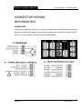
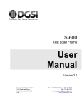
E-405
Smart Digital Indicator
User
Manual
Version 1.0
Durham Geo Slope Indicator
2175 West Park Court
Stone Mountain, GA 30087
USA
Phone: 800-837-0864 or +1.770.465.7557
Fax: 770.465.7447
e-mail: [email protected]
www.DurhamGeo.com
Disclaimer
Durham Geo-Enterprises, Inc. (including all affiliates to include its trade name of
DGSI) makes no representations or warranties with respect to the contents
hereof and specifically disclaim any implied warranties of merchantability or
fitness for any particular purpose. Durham Geo Slope Indicator reserves the right
to revise this publication and to make changes from time to time in its content
without obligations to notify any person or organization of such revision or
changes.
IMPORTANT
Before beginning installation procedures, these Installation and Operating Instructions
should be studied carefully. The installation and operation should also be in
accordance with local regulations and accepted codes of good practice.
Information Record
Model #:
_E-405______
Serial #: ______________
Sold By: ___________________
Date Purchased: _____________
The serial number for the unit is listed on the side of the pump head. You will
need this number if you call DGSI for service or support.
Version 1.0_
Page 2 of 23
Table of Contents
RECEIVING & UNPACKING........................................................................................................................ 4
SAFETY CONSIDERATIONS ...................................................................................................................... 4
CONNECTOR WIRING INFORMATION ...................................................................................................... 5
FRONT PANEL SETUP KEYS..................................................................................................................... 6
ENABLING & LOCKING OUT MENU ITEMS.............................................................................................. 8
READING COORDINATES OF 2 POINTS SCALING METHOD ............................................................... 9
DC VOLTS, AMPS, PROCESS, STRAIN .................................................................................................. 11
DUAL RELAY OUTPUT OPTION .............................................................................................................. 15
SERIAL COMMUNICATIONS OPTIONS................................................................................................... 17
EXCITATION OUTPUTS & POWER SUPPLY .......................................................................................... 20
METER CALIBRATION & SPECIFICATIONS........................................................................................... 21
Version 1.0_
Page 3 of 23
DIGITAL PANEL METER
R E C E I V I N G
&
U N P A C K I N G
RECEIVING & UNPACKING
Your meter was carefully tested and inspected prior to shipment. Should the meter be damaged
in shipment, notify the freight carrier immediately. In the event the meter is not configured as
ordered or the unit is inoperable, return it to the place of purchase for repair or replacement.
Please include a detailed description of the problem.
SAFETY CONSIDERATIONS
Warning: Use of this equipment in a manner other than specified may impair the
protection of the device and subject the user to a hazard. Visually inspect the unit for signs of
damage. If the unit is damaged, do not attempt to operate.
Caution:
•
This unit must be powered with AC (mains) from 95-240 Vac ±10% (90-300 Vdc) with the
high voltage power supply option, or 10-34 Vac ±10% (10-48 Vdc) with the low voltage
power supply option. Verify that the proper power option is installed for the power to be
used. This meter has no AC (mains) switch. It will be in operation as soon as power is
connected.
•
The 95-240 Vac (95-300 Vdc) mains connector (P1 Pins 1-3) is colored Green to
differentiate it from other input and output connectors. The 10-34 Vac (10-48 Vdc) mains
connector is colored Black.
•
Do not make signal wiring changes or connections when power is applied to the instrument.
Make signal connections before power is applied. If reconnection is required, disconnect the
AC (mains) power before such wiring is attempted.
•
To prevent electrical or fire hazard, do not expose the instrument to excessive moisture.
•
Do not operate the instrument in the presence of flammable gases or fumes; such an
environment constitutes a definite safety hazard. This meter is designed to be mounted in a
metal panel.
Symbols used
Caution (refer to accompanying
documents)
Earth (ground) terminal.
Caution, risk of electric shock.
Both direct
current.
and
alternating
Equipment protected throughout by double
insulation or reinforced insulation.
Version 1.0_
Page 4 of 23
R E C E I V I N G
DIGITAL PANEL METER
&
U N P A C K I N G
CONNECTOR WIRING
INFORMATION
CONNECTORS
Connectors for signal and power are U/L rated screw-clamp terminal blocks that plug into mating
jacks on the printed circuit board. Communication connectors are a single RJ11 plug for RS232,
dual RJ11 plugs for RS485, dual RJ45 plugs for RS485 Modbus.
P5 -
P2 -
Version 1.0_
Page 5 of 23
DIGITAL PANEL METER
F R O N T
P A N E L
S E T U P
K E Y S
FRONT PANEL SETUP KEYS
Meter Front Panel
There are four front panel keys, which change function for the Run Mode and Menu Mode,
effectively becoming eight keys. The keys are labeled with alphanumeric captions (MENU,
right arrow,
PEAK, RESET, ALARMS) for the Run Mode and with symbols (
right triangle, up triangle,
left arrow) for the Menu Mode.
FRONT PANEL LOCKOUT
The Menu Mode will not work with most meters as received from the factory, since all menu
items have been disabled in the software. Items under Loc 1, Loc 2 and Loc 3 then need to
be set to "0" via the front panel for these menu items to be unlocked See page 8. The
paragraphs below assume that all menu items have been unlocked.
MENU MODE KEY ACTION
In the Menu Mode, pressing a key momentarily advances to the next menu item. Holding
down a key automatically advances through multiple menu items for fast menu navigation.
KEYS IN RUN MODE
MENU Key. Pressing MENU from the Run Mode enters the Menu Mode.
Pressing MENU repeatedly will step the meter through the various menu items (if
these have not been locked out) and then back to the Run Mode.
PEAK Key. Pressing PEAK normally causes the peak value of the input signal
to be displayed. The peak display then blinks to differentiate it from the normal
present value display. Pressing PEAK again will return the display to the present value.
RESET Key. Pressing RESET with PEAK resets peak values. Pressing RESET
with ALARMS resets latched alarms. Pressing RESET with MENU performs a
meter reset (same as power on).
ALARMS Key. Pressing ALARMS once displays the setpoint for Alarm 1.
Pressing it again displays the setpoint for Alarm 2. Pressing it again returns to
the present value.
Version 1.0_
Page 6 of 23
DIGITAL PANEL METER
F R O N T
P A N E L
S E T U P
K E Y S
KEYS IN MENU MODE
Right Arrow Key (MENU). Pressing
steps the meter through all menu items that
have been enabled and then back to the Run Mode. With the DC signal
conditioner board and no option boards, available menu items are _InPut,
SEtuP, ConFG, _FiLtr, dEc.Pt, SCALE, OFFst, Loc 1, Loc 2, Loc 3. If a change has
been made to a menu item, that change is saved to non-volatile memory when the
key is pressed next, and StoreE is displayed briefly.
Right Triangle Key (Digit Select).
• Pressing
from the InPut menu brings up all meter functions available with the
meter's signal conditioner. For the DC signal conditioner, these are _dC U, _dC A
and _rAtio.
• Pressing
from the SEtuP, ConfFG, FiLtr, SCALE, OFFSt, Loc 1, Loc 2 or Loc 3
menus items sequentially selects digit positions 1 - 5, as indicated by a flashing digit:
00000, 00000, 00000, 00000, 00000.
from the dEC.Pt menu item sequentially selects decimal point positions,
• Pressing
which will flash: d.dddd dd.ddd ddd.dd dddd.d ddddd. .ddddd.
Up Triangle Key (Value Select). Pressing for a flashing item (digit position or
decimal point position) will increment that item. Pressing MENU will save any
changes.
Left Arrow Key (Reverse Menu). Pressing
has the same effect as the
MENU key, except that menu items are brought up in reverse order.
Version 1.0_
Page 7 of 23
DIGITAL PANEL METER
E N A B L I N G
&
L O C K I N G
O U T
M E N U
I T E M S
ENABLING & LOCKING OUT
MENU ITEMS
For security reasons and ease of meter operation, any and all menu items may be disabled or
"locked out" so that they are no longer directly accessible from the front panel. Each function to
be disabled is set to "1" in menu items Loc 1, Loc 2 or Loc 3, and each function to be enabled is
set to "0."
SETTING SOFTWARE LOCKOUTS
When setting up the meter, it may be necessary to enable specific menu items by setting the
corresponding lockout digit to 0. Be sure to reset the lockout digit to "1" if you do not want the
menu item to be changed by an operator.
Loc 1 Loc 2 Loc 3
MENU key until Loc 1, Loc 2 or Loc 3 is
Press the
displayed, as desired.
11111
Press
to display the lockout status, consisting of 1’s
and 0’s. The left digit will flash. Press
again to step to
the next digit, which will flash.
00000
12345
Press
to set the flashing digit to "0" to enable the
menu item or to "1" to disable. Press MENU to enter. See
the table to the right for list of menu items that can be
enabled or disabled.
Enabled or Disabled
Menu Items
Loc 1
1 - Input type selection.
2 - Meter setup, configuration
& decimal pt.
3 - Filter selection.
4 - Scale or Lo, Hi input.
5 - Offset or Lo, Hi reading
Loc 2
2 - Alarm setup.
3 - Alarm setpoint value
programming.
4 - Analog output scaling.
5 - Serial interface setup.
Loc 3
2 - View peak value
3 - View alarm setpoints
4 - Reset (peak & latched
alarms)
5 - Reset (meter reset)
Version 1.0_
Page 8 of 23
DIGITAL PANEL METER
R E A D I N G
C O O R D I N A T E S O F 2 P O I N T S
S C A L I N G M E T H O D
READING COORDINATES OF
2 POINTS SCALING METHOD
When the reading coordinates of 2 points* scaling method has been selected under SEtuP,
(see page 12) the four menu items below will appear ahead of all other menu items when the
MENU
or
key is first pressed from the run mode.
This scaling method applies a straight line fit between two points, which are determined from
actual transducer signals and the desired corresponding meter readings. A low signal, such
as the output of a pressure transducer at zero pressure, and high signal, such as the output
of the same transducer at a known high pressure, are applied to the meter. The desired
corresponding low and high readings are then entered from the front panel. The meter then
applies straight line fit between the high and low calibration points. This scaling method has
the advantage of calibrating the transducer and meter as a system. The actual voltage or
current at either point does not need to be known.
The programming example below is for a process meter used with a 4-20 mA pressure
transducer for 0 to 100 psi. Decimal points are set separately using the dEC.Pt menu.
Press Menu Select
Key
Lo In Apply low signal input
(e.g., transducer output for 0
psi).
Hi In Apply high signal input
(e.g., transducer output for
known 100.00 psi source).
Press Digit Select
Key
_40.21 Press to display
reading at low signal input
(e.g., 4.021 mA).
200.94 Press to display
reading at high signal input
(e.g., 20.094 mA).
Press Value Select
Key
_40.21 Press
reading.
to store low
200.94 Press
reading.
to store high
Lo rd
Mode to enter desired low
reading (e.g., 0.00).
000.00 000.00 000.00
000.00 000.00 Select digit
to flash.
100.00 Select -9 thru 9 for
flashing first digit, 0 thru 9 for
other flashing digits.
Hi rd
Mode to enter desired high
reading (e.g., 100.00).
000.00 000.00 000.00
000.00 000.00 Select digit
to flash.
100.00 Select -9 thru 9 for
flashing first digit, 0 thru 9 for
other flashing digits.
Version 1.0_
Page 9 of 23
DIGITAL PANEL METER
R E A D I N G
C O O R D I N A T E S O F 2 P O I N T S
S C A L I N G M E T H O D
Scaling method “Scale and Offset” if selected under SEtuP (see page 12)
SCALE
Scale factor*
0.0000 0.0000 0.0000
0.0000 0.0000 0.0000
Select digit to flash.
Select -9 thru 9 for flashing first digit, 0 thru 9
for other flashing digits. Select decimal point
location when decimal point is flashing.
OFFst
Offset value*
0.0000 0.0000 0.0000
0.0000 0.0000
SELECT DIGIT
TO FLASH.
Select -9 thru 9 for flashing first digit, 0 thru 9
for other flashing digits. Decimal point
location is selected by dEC.Pt.
Scaling method “Coordinates of 2 points” if selected under SEtuP
Lo In.
Low signal input.
Version 1.0_
0.0000 0.0000 0.0000
0.0000 0.0000
Select digit to flash.
Select -9 thru 9 for flashing first digit, 0 thru 9
for other flashing digits. Decimal point is set
by input range chosen.
Page 10 of 23
D C
DIGITAL PANEL METER
V O L T S ,
A M P S ,
P R O C E S S ,
S T R A I N
DC VOLTS, AMPS, PROCESS, STRAIN
The DC Volts, Amps, Process and Strain meters utilize the DC signal conditioner board, which
needs to be configured via jumpers for the desired voltage or current range. All signal ranges
are factory calibrated with calibration factors stored in EEPROM. The meter software recognizes
the board and will bring up the appropriate menu items for it; however, it does not recognize the
jumper settings. Please see further manual sections for setup of the following: relay output (15),
analog output (16), communication I/O (17), parallel BCD output (18), and transducer excitation
output (19).
Voltage Ranges
FS Input
±200.00 mV
±2.0000 V
±20.000 V
±200.00 V
±300V (UL)
±600V (not UL)
E1
E2
E3
B
A
A
B
B
B
B
f
f
h
h
g
g
b
a
b
a
a
a
A
h
Current Ranges
FS Input
±2.0000 mA
±20.000 mA
±200.00 mA
±5.000 A
a
E1
E2
E3
A
A
A
A
e, g
d, g
c, g
a, b, g
b
b
b
b
g
f
e
E1
E3 E2
b
c
b
d
a
1. Use 5 mm (0.2") jumpers for locations designated by a capital letter.
2. Use 2.5 mm (0.1") jumpers for locations designated by a lower case letter.
3. Store spare jumpers on an unused jumper post not associated a capital letter.
SCALE & OFFSET SETUP
For DC voltmeters & ammeters, a scale factor of 1 and an offset of 0 are used for direct
readings in (milli)volts or (milli)amperes. Decimal point selection does not affect the displayed
digits. For example, 0-20V or 0-20 mA signals can both be displayed as 0-20000. A full scale of
20000 may be displayed as 20.000 mA or 20000 µA. Use with a current shunt will require a
scale factor to be set. For example, for a 500-100 (500A, 100 mV) shunt, divide 5000 (the
desired full scale display with 0.1A resolution) by 10000 (displayed value with 100 mV when the
scale factor is 1.0) for a scale factor of 0.5.
Version 1.0_
Page 11 of 23
DIGITAL PANEL METER
D C
V O L T S ,
A M P S ,
P R O C E S S ,
S T R A I N
For process & strain meters, scaling is normally set up from the front panel using the
and
keys, but can also be set up via RS232/485 using special PC-compatible setup software
(available at no charge). The meter allows three scaling methods to be selected: 1) Scale and
offset*, 2) Coordinates of 2 points*, and 3) Reading coordinates of 2 points*. Only menu items
applicable to the selected method will be presented. Please see the Glossary for an explanation
of items marked by an *.
KEYSTOKES FOR SETUP
If the MENU
key does not work, see page 8 “Enabling & Locking Out Menu Items.”
Press Menu
Select Key
_InPut
Selection of signal
input type & range
SEtuP
Meter Setup
Version 1.0_
Press Digit
Select Key
Press Value Select
Key
_dC U
DC Volts
__0.2U __2.0U _20.0U 200.0U 660.0U
0.2, 2, 20, 200, 660V FS
_dC A
DC Amps
__2.0a _20.0a _200.0a _5.0a
0.2, 20, 200 mA, 5A FS.
_rAtio
Strain gauge & ratio
__0.2U __2.0U _20.0U
0.2, 2, 20V FS.
00_00
Display selection with
scale factor of 1.
0
1
2
3
00 _00
Power line frequency
0 Noise minimized for 60 Hz
1 Noise minimized for 50 Hz
00_ 00
Scaling method
0 Scale and offset method*
1 Coordinates of 2 points method*
2 Reading coordinates of 2 points method*
4-1/2 digits (±20,000)
Remote display* (±99,999)
4-1/2 digits, counts by 10 (±20,000)
3-1/2 digits (±2,000)
Page 12 of 23
DIGITAL PANEL METER
00_00
Operation of control
inputs 1 & 2:
True = logic 1 (0V or
tied to digital ground)
False = 0 (5V or open)
Press Menu
Select Key
ConFG
Meter Configuration
Version 1.0_
D C
V O L T S ,
A M P S ,
P R O C E S S ,
S T R A I N
1 = Reset*, 2 = Meter Hold*
1 = Function Reset*, 2 = Peak*or Valley*
1 = Hold*, 2 = Peak or Valley Display
1 = Hold*, 2 = Tare*
1 = Peak or Valley Display, 2 = Tare*
1 = Tare*, 2 = Reset*
1 = 1, 2 = 1, decimal point = XXXXX
1 = 0, 2 = 1, decimal point = XXXX.X
1 = 1, 2 = 0, decimal point = XXX.XX
1 = 0, 2 = 0, decimal point = XX.XXX
7 1 = 1, 2 = 1, decimal point = XXXX.X
1 = 0, 2 = 1, decimal point = XXX.XX
1 = 1, 2 = 0, decimal point = XX.XXX
A = 0, 2 = 0, decimal point = X.XXX.X
8 1 = Function Reset*, 2 = Display Blank*
9 1 = Hold*, 2 = Display Blank
A 1 = Peak or Valley, 2 = Display Blank*
B 1 = Tare*, 2 = Display Blank*
C 1 = Valley Display, 2 = Peak Display
D 1 = Tare*, 2 = Reset Tare to Zero
Both inputs 1 and 2 set to 1 for selections
2, 4, A, C = Function Reset*
Both inputs 1 and 2 set to 1 for selections
0, 1, 3, 5, 8, 9, B, D = Meter Reset*
0
1
2
3
4
5
6
Press Digit
Select Key
Press Value Select
Key
000 _0
Operation as a rate of
change meter*.
Extended meter* only.
0
1
2
3
4
5
6
Not rate of change
Rate x 0.1
Rate x 1
Rate x 10
Rate x 100
Rate x 1000
Rate x 10000
_0 _ _0
Operation of front
panel PEAK button and
rear connector for
Peak or Valley Display
0 Peak Display*. Also selects “Peak” in
“Peak or Valley” at connector above.
1 Valley Display*. Also selects “Valley” in
“Peak or Valley” at connector above.
2 Peak* (1st push), Valley* (2nd push)
3 Front panel Tare*
000 _ 0
Auto-tare
0 Meter comes up in normal run mode.
1 Meter comes up in auto-tare* mode
000 _ 0
Nonlinear input scaling
Extended meter* only.
0 Linear input
1 Custom curve linearization
Page 13 of 23
DIGITAL PANEL METER
FiLtr
Filtering
dEc.Pt
Dec. point selection
D C
V O L T S ,
A M P S ,
P R O C E S S ,
S T R A I N
00000
Alarm filtering
0 Unfiltered output
1 Filtered output
00000
Peak & Valley filtering
0 Unfiltered Peak* & Valley*
1 Filtered Peak* & Valley*
00000
Display filtering
0 Display batch average every 16 readings
1 Display filtered signal
00000 Adaptive filter
threshold
0 Low adaptive filter threshold level
1 High adaptive filter threshold level
00000
Input signal filtering.
Can be applied to display, setpoint, analog
output, data output.
0
1
2
3
4
5
6
7
8
9
A
d.dddd
Decimal point flashes.
d.dddd dd.ddd ddd.dd dddd.d ddddd.
Autofilter*
Batch average, 16 readings
Moving average*, 0.08 sec.
Moving average*, 0.15 sec.
Moving average*, 0.3 sec.
Moving average*, 0.6 sec.
Moving average*, 1.2 sec.
Moving average*, 2.4 sec.
Moving average*, 4.8 sec.
Moving average*, 9.6 sec.
Unfiltered
.ddddd Press
to shift the decimal point.
Option board dependent menu items
ALSEt. dEU1H dEU2H dEU1b dEU2b
Menu items related to alarm setup These will only appear if a relay board is detected. If so,
please see page 16.
SEr 1. SEr 2. SEr 3. SEr 4.
MENU ITEMS RELATED TO SERIAL COMMUNICATIONS.
THESE WILL ONLY APPEAR IF AN RS232 OR RS485 I/O
BOARD IS DETECTED. IF SO, SEE PAGE 19.
*
See Glossary for explanation of item.
Version 1.0_
Page 14 of 23
D U A L
DIGITAL PANEL METER
R E L A Y
O U T P U T
O P T I O N
DUAL RELAY OUTPUT OPTION
An optional dual contact relay board or dual solid state relay board may be may be installed in
the meter main board at plug position P12, adjacent to the power supply board. Once installed,
the relay board is recognized by the software, which will bring up the appropriate menu items.
These menu items will not be brought up if a relay board is not installed. Both relay boards offer
a choice of operating modes: latched* or non-latched*, hysteresis band*, deviation band*,
actuation based on the filtered or unfiltered signal, and selectable number of readings in alarm
zone to cause an alarm. Please see the Glossary at the end of this manual for an explanation of
terms marked by an *.
KEYSTROKES FOR VIEWING & CHANGING SETPOINTS
It is not necessary to enter the setup menu to view or change setpoints. This allows the meter to
continue conversions and provide outputs when setpoints are displayed. After pressing
(Alarms),
you have 30 seconds to enter a change, or the meter reverts to normal display.
Press Alarms
Key
Press Digit
Select Key
Press Value Select
Key
300.24
PRESS
(ALARMS) TO
DISPLAY ALARM
1 SETPOINT.
_200.00
Current setpoint 1 value blinks,
and Alarm 1 LED indicator lights.
Press to select a digit, which
will blink.
_295.00
To change setpoint 1 value,
press
to change selected
blinking digits.
395.00
PRESS
(ALARMS) TO
DISPLAY ALARM
2 SETPOINT.
_395.00
Current setpoint 2 value blinks,
and Alarm 2 LED indicator lights.
Press to select a digit, which
will blink.
_305.00
To change setpoint 2 value,
press
to change selected
blinking digits.
300.24 Press
Version 1.0_
(Alarms) again. The meter will reset and display the current reading.
Page 15 of 23
D U A L
DIGITAL PANEL METER
R E L A Y
O U T P U T
O P T I O N
KEYSTROKES FOR SETUP
If the MENU
key does not work, see page 8 “Enabling & Locking Out Menu Items.”
Press Menu
Select Key
ALSEt
ALARM
SETUP.
PRESS
UNTIL ALSET
IS
DISPLAYED
(WITH RELAY
BOARD).
Press Menu
Select Key
ALSEt
ALARM
SETUP.
(continued)
Press Digit
Select Key
Press Value Select
Key
00000
Relay state when alarm
is active.
0
1
2
3
Relay 1 on
Relay 1 off
Relay 1 on
Relay 1 off
00000
Alarm latching* or nonlatching* (auto reset).
0
1
2
3
Alarm 1 auto reset Alarm 2 auto reset
Alarm 1 latching
Alarm 2 auto reset
Alarm 1 auto reset Alarm 2 latching
Alarm 1 latching
Alarm 2 latching
Press Digit
Select Key
Relay 2 on
Relay 2 on
Relay 2 off
Relay 2 off
Press Value Select
Key
00000
ALARM
OPERATES AT
AND ABOVE
SETPOINT
(ACTIVE HIGH)
OR AT AND
BELOW
SETPOINT
(ACTIVE LOW).
0
1
2
3
4
5
6
7
8
AL1 active high
AL1 active low
AL1 disabled
AL1 active high
AL1 active low
AL1 disabled
AL1 active high
AL1 active low
AL1 disabled
AL2 active high
AL2 active high
AL2 active high
AL2 active low
AL2 active low
AL2 active low
AL2 disabled
AL2 disabled
AL2 disabled
00000
Hysteresis mode* or
band deviation mode*
0 AL1 band deviation
AL2 band
deviation
1 AL1 hysteresis
AL2 band
deviation
2 AL1 band deviation
AL2 hysteresis
3 AL1 hysteresis
AL2 hysteresis
4 No deviation or hysteresis in menu.
00000
Number of readings in
alarm zone to cause an
alarm.
0
1
2
3
4
5
6
7
After 1 reading
After 2 readings
After 4 readings
After 8 readings
After 16 readings
After 32 readings
After 64 readings
After 128 readings
* See Glossary for explanation of item.
Version 1.0_
Page 16 of 23
DIGITAL PANEL METER
S E R I A L
C O M M U N I C A T I O N S
O P T I O N S
SERIAL COMMUNICATIONS OPTIONS
An optional serial communications board (RS232, RS485 or RS485-Modbus) may be connected
to the meter main board at plug position P13 (middle position). Once installed, this board is
recognized by the meter, which will bring up the appropriate serial communication menu items.
These items will not be brought up if a communication board is not installed.
The RS485 and RS485-Modbus boards are electrically equivalent, but have a slightly different
physical layout. The RS485 version uses two RJ11 connectors, while the RS485-Modbus
version uses two RJ45 connectors for compliance with the Modbus standard. Both boards
feature dual connectors, which are wired in parallel to allow daisy chaining of addressable
meters with no need for a communications hub. All three boards are compatible with the same
serial three communication protocols, which are selectable under meter setup: Custom ASCII*,
Modbus* RTU, and Modbus* ASCII. Digital addressing of multiple meters on the same serial
communication line requires RS485 or RS485-Modbus boards.
BOARD SETUP VIA JUMPERS
RS232 Board
g - Normal operation.
h - Slave display operation to RS232 output of
another meter.
J - Pull-up resistor on RTS line.
Note: The board is shipped standard with jumpers
g and j installed.
RS485 and RS485-Modbus Boards
Full Duplex Operation
b & e - These bias jumpers should be installed on 1
(and only 1) meter.
a & d - installed on last meter in line with long cable
runs.
Half Duplex Operation
b & e - bias jumpers installed on 1 board.
c & f - installed for half duplex operation.
a - installed on last meter in line with long cable runs.
Note: The boards are shipped standard with no
jumpers installed.
Version 1.0_
Page 17 of 23
S E R I A L
DIGITAL PANEL METER
C O M M U N I C A T I O N S
O P T I O N S
KEYSTROKES FOR SETUP
If the MENU
key does not work, see page 8 “Enabling & Locking Out Menu Items.”
Press Menu
Select Key
.SEr 1.
FIXED
PARAMETERS:
NO PARITY
8 DATA BITS
1 STOP BIT
Press Digit Select
Key
__000
OUTPUT
FILTERING
0 Send unfiltered signal
1 Send filtered signal
__000U
Baud rate
0
1
2
3
4
5
6
300 baud
600 baud
1200 baud
2400 baud
4800 baud
9600 baud
19200 baud
0
1
2
3
4
5
6
7
8
9
60 Hz
Line frequency
0.28 sec
0.57 sec
1.1 sec
2.3 sec
4.5 sec
9.1 sec
18.1 sec
36.6 sec
72.5 sec
__000U
OUTPUT UPDATE
RATE
.SEr 2.
Serial Setup 2
.SEr 3.
Serial Setup 3
Version 1.0_
Press Value Select
Key
50 Hz
Line frequency
0.34 sec
0.68 sec
1.4 sec
2.7 sec
5.4 sec
10.9 sec
21.8 sec
43.5 sec
97 sec
_0000U
Line feed
0 No line feed after carriage return
1 Line feed after carriage
return
_0000U
Alarm data with readings
0 No alarm data
1 Alarm data with reading
_0000U
Control of data output
0 Continuous data output
1 Data output on ASCII command
only
_0000U
Meter address with
Custom ASCII protocol*
Select 0 thru F for addresses 1 thru
15.
Select 0. thru F. (with decimal point)
for addresses 16 thru 31.
00000U
Half or full duplex
0 Full duplex
1 Half duplex
00000U
Special start & stop char.
0 Standard continuous mode
1 Special start & stop characters
Page 18 of 23
S E R I A L
DIGITAL PANEL METER
Press Menu
Select Key
.SEr 3.
Serial Setup 3
(continued)
SEr 4.
Serial Setup 4
_Addr
Modbus Address
C O M M U N I C A T I O N S
00000U
RTS mode
0 Normal RTS
1 Single transmission
00000U
Termination characters
0 Only at end of all items
1 At end of each item
Press Digit Select
Key
O P T I O N S
Press Value Select
Key
00000U
DATA SENT IN
CONTINUOUS
MODE
0
1
2
3
4
5
Reading
Peak
Valley
Reading + peak
Reading + valley
Reading + peak + valley
__000U
Modbus* ASCII gap
timeout
0
1
2
3
1 sec
3 sec
5 sec
10 sec
__000U
Serial protocol
0 Custom ASCII*
1 Modbus* RTU
2 Modbus* ASCII
__000U
PARITY
0 None
1 Odd
2 Even
__000 __000 __000
Select digit to flash.
__158
Select 0 through 9 for flashing digit.
Address range is 1 to 247.
* See Glossary for explanation of item.
Version 1.0_
Page 19 of 23
DIGITAL PANEL METER
E X C I T A T I O N
O U T P U T S
&
P O W E R
S U P P L Y
EXCITATION OUTPUTS & POWER SUPPLY
Three isolated transducer excitation output levels are available from the power supply board.
These are selectable via jumpers b, c, d, e, f in the upper right of the board, as illustrated.
In addition, the board provides three jumper positions for special features. The same jumper
locations apply to the universal power supply (95-240 Vac ±10% and 95-300 Vdc ±10%) and
to the low voltage power supply (10-34 Vac & 10-48 Vdc).
Excitation output
Jumper locations
5 Vdc ±5%, 100 mA max
b, d, e
10 Vdc ±5%, 120 mA max
b, d, f
24 Vdc ±5%, 50 mA max
c
SELECTION OF OTHER JUMPERS
Jumper a
Jumper g
Jumper h
Version 1.0_
-
Front panel menu lockout, locked when installed. See page 8)
Provides +5V power output at P1-4 when installed.
Connects "Control Input 2" to P1-4 when installed.
Page 20 of 23
DIGITAL PANEL METER
M E T E R
C A L I B R A T I O N
&
S P E C I F I C A T I O N S
METER CALIBRATION & SPECIFICATIONS
All analog input and analog output ranges of the meter have been digitally calibrated at the
factory prior to shipment using calibration equipment certified to NIST standards. Calibration
constants are stored digitally in non-volatile memory in EEPROM on the signal conditioner
board and analog output board. As a result, these boards may be mixed and interchanged
without requiring meter recalibration. Digital calibration eliminates much of circuitry that would
be associated with analog calibration, providing superior long term accuracy and stability.
If recalibration is required, the meter may be returned to the factory or to any authorized
distributor.
BASIC METER
Display
Type...................................... 5 LED, 7-segment, 14.2mm (.56") high digits & 3 LED indicators
Color ......................................................................................................................Red or green
Range ...................................................................... -99999 to +99999 and -99990 to +99990
A to D Conversion
Technique (Pat.5,262,780) ........................................................................Concurrent SlopeTM
Read Rate .................................................................60/s for 60 Hz NMR, 50/s for 50 Hz NMR
Output Update Rate....................................................................... 56/s at 60 Hz, 47/s at 50 Hz
Display Update Rate....................................................................... 3.5/s at 60 Hz, 3/s at 50 Hz
Noise Rejection
CMV from DC to 60 Hz..................................................................................Withstand 250Vac
Dielectric strength......................................................... 3.5 kV ac for 5 sec, 2.3 kV ac for 1 min
CMR from DC to 60 Hz................................................................................................... 130 dB
NMR at 50/60 Hz ................................................................ 90 dB with minimum digital filtering
Control Inputs (CMOS/TTL levels, logic 1 = tied to digital ground, logic 0 = open)
/ Hold input ............................................................................Logic 1 holds display and outputs
/ Peak input.....................................................................................Logic 1 displays peak value
/ Tare input ........................................................................... Logic 1 offsets input value to zero
/ Reset input .......................................................................... Logic 1 resets all meter functions
/ Function Reset input................................................... Logic 1 resets peak values and alarms
/ Decimal Point input....................... Overrides internal DP selections and controls DP position
Version 1.0_
Page 21 of 23
M E T E R
DIGITAL PANEL METER
C A L I B R A T I O N
&
S P E C I F I C A T I O N S
Accuracy
Load Cell Input
Input Range
Resolution
Output
Zero
Range
Output
Span
Range
20.000 mV 1 µV
50.000 mV 2.5 µV -99999
to 0 to ±99,999
100.00 mV 5 µV
250.00 mV 12.5 µV 99999
500.00 mV 25 µV
Error at 25°C
0.01%
of FS
±1 Ct
Ratio
Current Range
Resolution
200.00 mV
2.0000 V
20.000 V
10 µV
100 µV
1 mV
Input
Ohms
1 GΩ
1 GΩ
1 MΩ
Error at
25°C
0.01%
of FS
±2 Cts
Span Tempco ...........................................................................................0.003% of reading/°C
.................................................................................. 0.0015% of reading/°C for load cell meter
Zero Tempco .............................................................................................................. 0.2 µV/°C
Reference Junction Accuracy .......................................................................1°C, 10°C to 40°C
POWER REQUIREMENTS
Input Voltage rating (standard) .................................... 95-240V ac ±10% or 90-300V dc ±10%
Input Voltage rating (low voltage option) ..............................................10-34V ac or 10-48V dc
Power Line Frequency.................................................................................... DC and 47-63 Hz
Power Consumption, Max ..............................................................................................5 Watts
EXCITATION OUTPUTS
Voltage & Current Levels (jumper selectable) .................................... 5V dc ±5%, 100 mA max
.......................................................................................................... 10V dc ±5%, 120 mA max
........................................................................................................... 24V dc ± 5%, 40 mA max
Excitation Output Ripple .......................................................................................100 mVp max
Isolation from power and outputs ..................................................................................250 Vac
Insulation dielectric strength to power and outputs ...... 3.5 kV ac for 5 sec, 2.3 kV ac for 1 min
Isolation to signal common ..............................................................................................50V dc
Version 1.0_
Page 22 of 23
DIGITAL PANEL METER
M E T E R
C A L I B R A T I O N
&
S P E C I F I C A T I O N S
DUAL RELAY OPTION
Power to Relay Option...................................................................................Powered by meter
Setpoint Setup .........................................................Via front panel pushbuttons or RS232/485
Update Rate .................................................................................. 56/s at 60 Hz, 47/s at 50 Hz
Response to input signal (min) ....................................................................Display update rate
Input Signal (selectable) ..........................................................Filtered or unfiltered input signal
Actuation Modes (selectable) ........Above or below setpoint, latching or non-latching, disabled
Output Time Delay (selectable) ...................................................................... 1 to 128 readings
Front Panel Enable / Lockout Modes (selectable)..................1) Display and change setpoints
......................................................................................2) Display but do not change setpoints
.................................................................................... 3) Neither display nor change setpoints
Alarm Status Indication.................................................................................... 2 red LED lamps
Status Indication Setup (selectable) ........................ Lit when output is ON or OFF, or disabled
Contact Relay Output:
AC Rating ............................................................................................................8A @ 240V ac
DC Rating ..............................................................................................................8A @ 24V dc
Isolation rating between signal common and contacts ..................................................250V ac
Insulation dielectric strength between signal common and contacts..........................................
...................................................................................... 3.5 kV ac for 5 sec, 2.3 kV ac for 1 min
Solid State Relay Output:
AC Rating ........................................................120 mA @ 125V ac, 24 ohms series resistance
DC Rating ..........................................................240 mA @ 150V dc, 6 ohms series resistance
Isolation rating between signal common and contacts ..................................................250V ac
Insulation dielectric strength between signal common and contacts..........................................
...................................................................................... 3.5 kV ac for 5 sec, 2.3 kV ac for 1 min
SERIAL INTERFACE OPTION (RS232, RS485, RS485-Modbus boards)
Power to Interface Option..............................................................................Powered by meter
RS485 Wiring ................................................................................................. Half or full duplex
Baud Rates...............................................................300, 600, 1200, 2400, 4800, 9600, 19200
Serial Protocols ...........................Custom ASCII*, Modbus* RTU, Modbus* ASCII (selectable)
Signal Levels ...................................................................... Meet RS232 and RS485 standards
Connectors .................. Single RJ11 (RS232), two RJ11 (RS485), two RJ45 (RS485-Modbus)
Isolation rating between signal common and serial I/O .................................................250V ac
Insulation dielectric strength between signal common and serial I/O.........................................
...................................................................................... 3.5 kV ac for 5 sec, 2.3 kV ac for 1 min
ENVIRONMENTAL
Operating Temperature ...........................................................................................0°C to 55°C
Storage Temperature .......................................................................................... -40°C to 85°C
Relative Humidity.........................................................95% from 0°C to 40°C, non-condensing
Case ........................................................................ NEMA-4X from front when panel mounted
Shock..............................................................................10 G at 1 kHz, applied in X, Y, Z axes
Vibration ...............................................15 Hz to 150 Hz, 1 mm to 2 mm amplitude, 20 G max.
Version 1.0_
Page 23 of 23