1
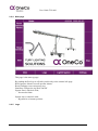
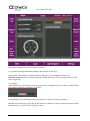
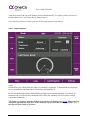
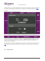
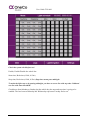
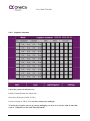
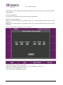
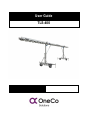
User Guide
TLS-400
User Guide TLS-400
Table of contents
1
General ..................................................................................................................... 3
1.1 Secure the rig ................................................................................................ 3
1.2 Connecting power ......................................................................................... 3
2
Operating the system ............................................................................................. 4
2.1 Daily use on/off ............................................................................................. 4
2.2 Operator screen ............................................................................................ 4
2.2.1
2.2.2
2.2.3
2.2.4
2.2.5
2.2.6
2.2.7
2.2.8
2.2.9
2.3
2.4
2.5
Physical Buttons ............................................................................................... 5
Menu................................................................................................................... 5
Alarm page......................................................................................................... 6
Main page........................................................................................................... 8
Legs.................................................................................................................... 8
Light/Irrigation ................................................................................................. 10
Light schedule ................................................................................................. 11
Irrigation schedule .......................................................................................... 13
Settings ............................................................................................................ 14
Emergency stop .......................................................................................... 16
Buzzer and blitz ........................................................................................... 16
Quick operating procedure ........................................................................ 16
3
Troubleshooting .................................................................................................... 16
4
Contact information .............................................................................................. 18
Side 2 av 18
User Guide TLS-400
1
General
This user guide describes how to operate the light rig. If something not described in this user
guide happens, contact your manufacturer immediately.
This system is not constructed to be driven high frequency up and down.
If there is too much wind the rig will lower itself down without any warning!
1.1
Secure the rig
1. Place the rig on a flat surface
2. Establish outriggers
3. Make sure the wind sensor is intact.
4. Turn the boom section extensions (if desired).
1.2
Connecting power
1. Connect 400V 63A ( L1, L2, L3, N, PE) on each socket on leg 1.
2. Strain relief both cables.
Side 3 av 18
User Guide TLS-400
2
Operating the system
This chapter will describe how to operate the system.
2.1
Daily use on/off
After connecting the power the buzzer and the blitz will be activated. This is because the emergency stop function needs to be reset!
Mode On procedure;
1. Ensure that the emergency stop button is not activated 2.3.
2. Push the emergency reset button at main page. The buzzer and the blitz will be deactivated.
3. Ensure that there are no alarms on the alarm banner.
4. Push system start button on the main page 2.2.4.
5. Ensure that mode in the screen heading changes to Mode: On 2.2.4.
Mode Off procedure;
If emergency stop has been activated the rig enters off mode automatically!
1. Lower the rig to the bottom position
2. Push the system off button on the main page 2.2.4.
2.2
Operator screen
This chapter describes how to use the operator screen.
Side 4 av 18
User Guide TLS-400
2.2.1
Physical Buttons
Each button beside the screen represent the action described in the nearby text. This changes
from page to page.
– “PREV” allows you to enter previous page.
+ “NEXT” allows you to enter next page (if prev has been used).
HOME opens Main page.
ALARM open alarms page.
2.2.2
Menu
This is the general heading.
This represents real time and date. (hh:mm:ss yyyy-mm-dd)
The system clock is very important because off the weekly timer function!!
Side 5 av 18
User Guide TLS-400
This is the alarm banner. This shows you the latest alarm.
This is located leftside of Mode.
This indicates light rig is moving/moving soon or emergency stop is released.
This indicates the mode of the rig. Off/On
The “Legs” text indicate which page you’re on.
This allows you to navigate to your desired destination.
2.2.3
Alarm page
Colors code alarms:
Active background/foreground: Red/Black
Inactive background/foreground: Black/Red
Acknowledge background/foreground: Orange/Black
Colors code warnings:
Active background/foreground: Yellow/Black
Inactive background/foreground: Black/Yellow
Acknowledge background/foreground: Orange/Black
Side 6 av 18
User Guide TLS-400
Active: Not acknowledge active alarm
Acknowledge: Acknowledge active alarm
Inactive: Not acknowledge inactive alarm
Returns to previous page.
Acknowledge selected alarm.
Increases text size.
Shows object info, if any.
Scrolls one page up.
Scrolls one page down.
Jumos to info block conntected to the alarm.
This shows which collation you have, and allows you to sort alarms by pushing alarms or warnings.
Side 7 av 18
User Guide TLS-400
2.2.4
Main page
This page is the start-up page.
By pushing the RA logo it will take you directly to the contact info page.
Rest Operator Alarms reset all operator alarms.
Reset EmStopp resets emergenzy stop.
Start/Stop Changes the rig mode On/Off.
System start is interlock with;
- No encoder faults
System stop is interlock with;
- Rig must be at bottom position.
2.2.5
Legs
Side 8 av 18
User Guide TLS-400
Wind sensor indicates wind in real-time (0-50m/s).
Leg positions and leg indication simulates the position off the legs.
Some alarms will make the rig stop and the Emergency lowering button can be used.
Hold the button for 5 sec to release the brake for the desired leg. The rig will then lower itself
down by gravity.
Leg control:
Auto/Manual up raises the rig to the top position (See settings) but first you have to confirm that
the outriggers and the wind sensor is in place.
By pushing auto up/ hold manual up, the rig will rise until it reaches top position.
Manual down lowers the rig as long as the button is pushed. For safety reasons you have to hold
the button for 5 sec before the rig starts to move.
Side 9 av 18
User Guide TLS-400
Auto down lowers the rig to the bottom position automatically. For safety reasons you have to
hold the button for 5 sec before the rig starts to move.
If the rig rises or lowers in auto, you can use the stop button to stop the rig.
2.2.6
Light/Irrigation
Light:
Status shows you which mode the light is in, manual or automatic. Command shows which status is commanded, and status shows which state the lights are at.
In auto mode the light will be controlled by the light sensor and the schedule (if enabled). In
manual mode, you choose the commands off to 100% the schedule will work on the chosen
command (if enabled).
The lights are equipped with time delay between modes. Se Settings page 2.2.9. When entering
100%from off mode the light start at 50% and after the decided time it switch on 100%. It’s
the opposite from 100% to off mode.
Side 10 av 18
User Guide TLS-400
Schedule allows you to enable and disable the weekly timer schedule, the result is the output off
the schedule. By pushing the schedule button it navigates you to the light-schedule page 2.2.7
Irrigation:
To enter Irrigation push the Irrigation button.
Status/control allows you to enable the irrigation system if the schedule is disabled. When enabling the irrigation system manually, there will be a 1 minute delay before it starts. The Time
on desires how long the irrigations system shall be enabled. If the schedule is enabled it overrides the operator command.
Schedule allows you to enable and disable the weekly timer schedule, the result is the output off
the schedule. By pushing the schedule button it navigates you to the irrigation-schedule page
2.2.8
2.2.7
Light schedule
Side 11 av 18
User Guide TLS-400
Check the system clock before use!
Enable; Enable/Disable the whole line.
Start time; Real-time (0-24h, 0-59m)
Stop time; Real-time (0-24h, 0-59m) Stop time cannot pass midnight.
To make the light stay on by passing midnight, you have to set on line with stop time 24.00 and
one line with start time 00.00.
Checkboxes from Monday to Sunday decides which day the start and stop time is going to be
enabled. The box between Monday and Wednesday represents Tuesday and so on.
Side 12 av 18
User Guide TLS-400
2.2.8
Irrigation schedule
Check the system clock before use!
Enable; Enable/Disable the whole line.
Start time; Real-time (0-24h, 0-59m)
On time; Period (0-24h, 0-59m) on time cannot pass midnight.
To make the irrigation stay on by passing midnight, you have to set on line with on time that
ends at 24.00 and one line with start time 00.00.
Side 13 av 18
User Guide TLS-400
Checkboxes from Monday to Sunday decides which day the start and stop time is going to be
enabled. The box between Monday and Wednesday represents Tuesday and so on.
2.2.9
Settings
This is the operator settings, to change any parameters you have to be loged in ass operator. If
you forget to log out, you wil be auto loged off after 10 minutes.
Light settings:
Mode 50/100 delay: Delay from off mode to 100% light and conversely. The light will be set at
50% at the decided time.
Auto mode light settings [µmol]: (0-2500)
Low limit: If the light gets under this, the lights will be set at 100%.
High limit: If the light gets over this, the lights will be set off.
In between low and high limit the lights will be set at 50%.
Hysteresis: how much the light needs to go under/over the high/low limit to reset itself. By pushing the “?” button, you will get information on how it works.
Side 14 av 18
User Guide TLS-400
Limit delay [m]: How long time in minutes the light needs to be under/over the limit before the
light changes.
Encoder settings [m]:
Top position: Top position of the rig according to leg position.
Run-time counter lights [h]:
Boom 1; Total; total runtime. Trip; Runtime since reset. The reset button allows you to reset the
trip meter.
Boom 2; Total; total runtime. Trip; Runtime since reset. The reset button allows you to reset the
trip meter.
Set Time Date button, navigates you in to this site;
This allows you to set the system clock.
(Hour: 0-23, Minute 0-59, Second 0-59, Year 0-99, Month 1-12, Day 1-31)
Error occurs if the combination is wrong.
This clock is for controlling the system.
Side 15 av 18
User Guide TLS-400
2.3
Emergency stop
Emergency stop buttons are located on the pannel! Emergency stop buttons are designed to be
used in emergency ONLY!
When connecting the power, you have to push the emergenzy reset button on main page to be
able to enter on mode.
Emergency stop procedure;
1. Emergency occurs.
2. Push the emergency button.
3. The unit will stop immediately and enter off mode.
4. Remove the emergency.
5. Turn the emergency button to the right to release it.
6. Push the emergency reset button on main page.
7. Push system start button on the operator screen 2.2.4.
8. System is ready to be set in action again.
2.4
Buzzer and blitz
Buzzer and blitz is indicating a moving action. When lowering the unit the buzzer and the blitz
will be activated in 5 seconds before the action take place.
2.5
Quick operating procedure
1. Secure the rig 1.1.
2. Connect the power 1.2.
3. Push the reset emergency button 2.3.
4. Push system start 2.2.4.
5. Control the light and the irrigation 2.2.6.
6. Push auto up button on Legs page 2.2.5.
7. Confirm that the outriggers and the wind sensor are in place 2.2.5.
8. Push auto down to lower the rig 2.2.5.
9. Push system stop 2.2.4.
10. Disconnect the power.
3
Troubleshooting
IF ANY ALARM APPEARS; LOWER THE RIG ALL THE WAY DOWN BEFORE ANY
ACTIONS ARE TAKEN!
To be able to reset any alarm that concerning the legs, the rig have to be at bottom position.
Side 16 av 18
User Guide TLS-400
The rig have an work level between 2.64m up to 4.40m. If under any circumstances the rig is
outside this range by more than 0.01m, contact manufacturer!
Alarm text:
Emergency stop activated
Wind sensor HH alarm
Wind sensor fault
Q10 Motor 1 tripped
Q11 Motor 2 tripped
Motor 1 starter error
Motor 2 starter error
Leg 1 encoder error
Leg 2 encoder error
Leg 1 High deviation
Leg 2 High deviation
Light sensor fault
Leg 1 Low deviation
Leg 2 Low deviation
Leg 1 wrong direction
Leg 2 wrong direction
F13 Phase guard fuse
Action:
Remove the emergency, releasethe button by
turning it to the right. Push the reset button.
Push “System start”.
Wait until the wind decreases.
Check that the plug underneath the sensor is in
place. Contact manufacturer.
Open the cabinet on-top of the rig. Locate
component –Q10 Push the switch to on. If this
alarm appears again, contact manufacturer.
Open the cabinet on-top of the rig. Locate
component –Q11 Push the switch to on. If this
alarm appears again, contact manufacturer.
Reset alarm then try again. If it appears again,
contact manufacturer.
Reset alarm then try again. If it appears again,
contact manufacturer.
Contact manufacturer.
Contact manufacturer.
Contact manufacturer.
Contact manufacturer.
Reset alarm then try again. If it appears again,
contact manufacturer.
Contact manufacturer.
Contact manufacturer.
Contact manufacturer.
Contact manufacturer.
Open the cabinet and reset Fuse F13, if it appears again, contact manufacturer.
Side 17 av 18
User Guide TLS-400
4
Contact information
Turf Lightning Solutions
+47 51819750
+47 94532161
+47 94532165
www.ra-tls.com
Side 18 av 18