1
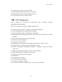
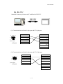
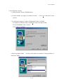
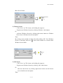
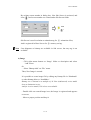
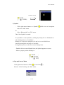
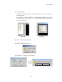
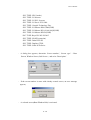
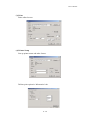
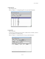
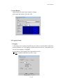
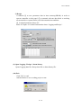
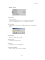
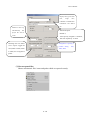
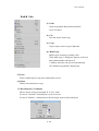
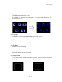
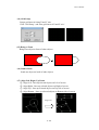
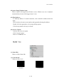
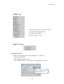
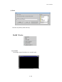
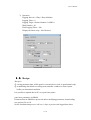
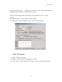
User’s Manual
Chapter1
1 . Introduction
[feature]
1.1
1 Distinctions
(1) Variable Display Devices
High-Resolution, High-Brightness Color
TFT(12.1”, 10.4”, 5.5”), STN Mono LCD(5.7”, Black & White, Blue)
STN Color LCD(5.7”, 7.5”, 10.4”)
(2) High speed 32bit RISC CPU(ARM processor)
(3) Front Water & Dust Proof : IP65F
(4) Ultra Slim Design for Panel Mounting
(5) Serial Communication Port and Parallel Print Port
(6) Resistive Matrix/Analog Touch Key
(7) Flash Memory for Screen Saving(Max. 4M)
(8) High speed graphic Controller
(9) Downloadable Operating System Software and Character Font Data
(10) Graphics and Tags for Dynamic User Interface
(11) Various Language Support such as Korean, Chinese, English, Japanese, etc
(12) Many Kinds of Controller Communication Drivers
(13) Windows-Based HMI System Design Software Tool
(14) Controller Communication Diagnosis Mode : Protocol Analyzer Function
(15) Recipe Function for Data or Parameter Batch Input
(16) Data Logging
1-1
User’s Manual
(17) Usable inner memory of System buffer
(18) Direct/Indirect addressing to PLC or controller
(19) Upload function( Screen/Logging/Recipe data )
(20) All windows fonts are usable to input
1.2
2 S/W’s Distinctions
This is software for drawing and transmission, and is software performs
programming and debugging.
This S/W is designed to operate on IBM compatible PC
(1)
(2)
(3)
(4)
Windows based Software : Windows 95/98/Me/NT/2000/XP
Project Management for Integrated Environment
Object Oriented Graphics and Dynamic Tags Editor
Downloadable Operating System Software and Character Font Data for System
Upgrade
(5) Easy to use Graphic Object and Tag Tool Bar
(6) Viewable Screen Thumbnail
(7) Automatic Screen Saving
(8) Enlargement of Screen for Detail Graphic Design (100%, 200%, 300%)
(9) Printing Tag List as Microsoft Excel Worksheet format
(10) Screen Components Information Windows : Diagrams, Tags and Selected
objects List
(11) Internal Communication Memory Area : System Buffers
(12) Direct/Indirect Device Memory Assignment
(13) System Components Library Support
(14) Simulation
(15) Transparent text support
(16) Transparent bitmap support
(17) All fonts of Windows support
(18) About movement & resizing, Usage of Arrow keys is possible
1-2
User’s Manual
[Screen shot of S/W]
1.3
3 Connection to Panel
After completion of programming, click ‘Transmit’. All composed screen files are
compiled into one file and saved.
It transmits compiled file through RS-232C
port.
1-3
User’s Manual
1.3
3.1
1RS-232C
Standard Connector pin between PC and Panel is RS-232C
(1) Connection between Panel’s 6pin port and PC’s 9pin port
1
5
6
3
4
1
2
[rear view
of Panel]
1
CD
2
RD
2
RD
3
SG
3
SD
4
4
5
5
SG
6
DSR
7
RTS
8
CTS
6
SD
9
(2) Connection between Panel’s 6pin port and PC’s 25pin port
1
6
5
3
4
2
1
[rear view
of Panel]
1
2
RD
2
SD
3
SG
3
RD
4
4
5
5
6
SD
6
7
8
20
1-4
SG
User’s Manual
Chapter2
2 . Installation
Requirements to install software are as follows
Item
Operational Standards
Above IBM PC AT Compatible
Recommended above Celeron 233
Above 64Mbyte,
Recommended above 128Mbyte
One 3.5 inch drive
Recommended above 40Mbyte
-Not the total size of Hard Disk
More than one Serial Communication port
(For data communication)
Above SVGA(800*600) 16bit colors
Recommended above 1024*768
Windows compatible Keyboard
Windows compatible Mouse
Windows compatible Printer
Above Windows 95/98/Me/NT/2k/XP
PC
Memory
FDD
HDD
Serial Port
Graphic Adapter
and Monitor
Key board
Mouse
Printer
Recommended O.S Environment
Note : S/W may not operate under non-standard environment which is different with
above specified ‘Operational Standard’
2.1
1 Contents of Package
- Touch Panel
- User’s Manual
- Install CD
* Communication cable is ‘Option’
2.2
2 Installation
Installation process is same with Windows 95/98/Me/NT 4.0/2000/XP
To install this S/W, run ‘Install CD’ on Windows.
Installation CD has self-extraction setup file(“*VxxxEng.exe”. This could be changed
2-1
User’s Manual
by new upgrade version)
(1) Insert Insstall CD into CD-ROM Drive.
(2) Asked whether you agree on ‘software License’.
process.
Click ‘Yes’ and move to next
(3) A dialog box appears, it shows ‘Destination Folder’ to install.
To install in a different folder, click Browse and select other folder.
To stop installation, click ‘Cancel’.
Click ‘Next’ to continue.
(4) Select program folder. You may select other one from the ‘Existing Folders’ or
make new folder.
2-2
User’s Manual
(5) It starts copying files from CD to computer.
(6) Click ‘Finish’ to finish installation.
(7) After completion of installation, The program group and icon are created on
program group.
(8) Browsing the installed folder, The folders(OS, Demo, Bitmap, lib-xxx6, libxxx3, lib-xxxC) can be seen. OS folder has the firmware of most proper version.
Demo folder has demo project files by model. Lib-xxxx folders have libraries for
model. Bitmap folder has bitmap files used in touch or lamp tag.
2-3
User’s Manual
Chapter3
3 . Basic Directions
Click ‘Start’ button on active desktop.
Select ‘Program’ menu and run this software.
It is easy to click icon on active desktop.
3.1
1 Basic Functions
‘Screen Edit, Message Edit, Alarm Edit, Simulation, etc’ are available simultaneously in
main program.
Project file consists of ‘Screen data, Message data, Alarm data, Image data, Logging &
Recipe data’ and project file is saved as just one file.
* Communication Function between PC and Panel
- O/S Program download
- Font Download
- Project file transmission
- Upload(Screen, Logging 1 & 2, Recipe, Alarm history)
- Simulation
3.2
2 Menu
Tool Bar
Menu Bar before ‘Project file’ is not
activated
Tool Bar
Information Window
Project Window
Status Bar
3-1
User’s Manual
Project window appears on left, and information window on right.
On ‘Project’ menu,
- click ‘ Open Project’ to open composed project
- or click ‘New Project’ to create new project,
and then all menu are activated.
This picture shows when new project file is created.
(1) Project window
Project Window has ‘Base screen, Window screen, Sub-screen, Message, Alarm,
Image, Symbol’ folders by tree view. Whenever new item is created, the icon is
added to the relevant folder.
1) Base screen
- Click ‘New’ on ‘File’ menu, and a dialog box appears.
- Click ‘Base’ radio button and register New Base Screen.
Or
- Click right mouse button on ‘Base’ screen icon or Base screen
description on Project Window Screen, it comes to same result.
Then,
By writing screen number in dialog box and pushing ‘OK’, New Base
Screen is activated, and icon ( ) and screen number are created under
3-2
User’s Manual
Base Screen folder.
2) Window Screen
- Click ‘New’ on ‘File’ menu, and a dialog box appears.
- Register new Window Screen by clicking ‘Window’ radio button
Or
- Add new Window Screen by clicking right mouse button on Window
Screen icon or Window Screen description.
Then
By writing screen number in dialog box and pushing ‘OK’, New Window
Screen is activated, and icon ( ) and screen number are created under
Window Screen folder.
1
3) Sub Screen
- Click ‘New’ on ‘File’ menu, and a dialog box appears.
- Register new Window Screen by clicking ‘Sub’ radio button
Or
- Add new Sub Screen by clicking right mouse button on Sub Screen
icon or Sub Screen description.
Then
3-3
User’s Manual
By writing screen number in dialog box, New Sub Screen is activated, and
icon ( ) and screen number are created under Sub Screen folder.
Sub
1
Sub Screen is used in relation to animation tag for ① animation effect,
And is registered in Base Screen for ② memory saving.
Note : Just diagrams or bitmap are available in Sub screen, but any tag is not
available.
4) Image
- Click right mouse button on ‘Image’ folder or description and select
‘Add’ menu.
Or
- Select ‘Bitmap-Add’ on ‘File’ menu.
Then, New Image is created.
It is possible to create image file by editing any bitmap file in ‘Paintbrush’
or other bitmap editor or ‘IconMaker’.
Bitmap size is limited as a multiple of 16. But A(Advanced) series model
have no limitation in size.
And for A series model, 256 colors are available.
- Double-click on created Image icon, the Image is registered and appears
on screen,
- Move to proper position and drop it.
3-4
User’s Manual
On Double-clicking
5) Symbol
-
Click right mouse button on ‘Symbol’(
)folder icon or description
and select ‘Add’ menu.
Or
- Select ‘Bitmap-Add’ on ‘File’ menu.
Then, New Symbol is created.
It is possible to create Symbol by editing any bitmap file in ‘Paintbrush’ or
other bitmap editor or ‘Icon Maker’.
Bitmap size is limited as multiple of 16 and can’t exceed 96*96 size.
And only mono(black and white) is available.
Saving bitmap file, save the file as mono bitmap form.
- Double-click on created Symbol icon, the Symbol appears on screen,
- Move to proper position and drop it.
6) Pop up(Context) Menu
Click right mouse button on folder(
) or sub-item(
It shows ‘Allow Docking’ & ‘ Hide’ menu.
3-5
)
User’s Manual
① Allow Docking
- Checked : Project Window or Information Window can be attached to
the main frame
- Not checked : Project Window or Information Window can not be
attached to the main frame. So it allows float Project Window or
Information Window.
[Docking]
[Floating]
② Hide : Hides Project Window
③ Delete : Deletes the Screen.
④ Renumber : Changes screen number.
Yes
3-6
No
User’s Manual
⑤ Modify Description : Modifies or changes description.
(2) Information Window
Information Window shows the list of Diagrams, Tags which are registered on
the active Screen. And it is possible to select any object in Information
Window. Click any object, the object’s state turn into selection mode, that is,
the object’s edge turns white point.
Information Window consists of 3 tabs, ‘Diagram’, ‘Tag’, ‘Selected’
1) Diagram : Shows created diagrams as like Images, Symbols, other diagrams
on the current screen.
2) Tag : Shows created tags on the current screen.
3) Selected : Shows selected object(s) on the current screen.
1)
3)
2)
3-7
User’s Manual
3.3
3 Tool Bar
Tool bars and the description ;
Tool
Description
New Project
Delete File
Open Project
Save Project
Print Project
S/W’s Information
Move left 1 dot
Move right 1 dot
Move up 1 dot
Move down 1 dot
Snap to Grid
Toggle Grid
Grid Setup
Re-draw
Cut
Copy
Paste
Multi Copy
Delete Object
Group
Release Group
Align Left
Align Right
Align Top
Align Bottom
Bring to Front
Send to Back
Find Address
ExGraph2 Tag
Find an address
Tool
Description
Numeric Tag
Touch Tag
Lamp Tag
Clock Tag
Character Tag
Message Tag
Alarm Tag
Key-indication Tag
Bar Graph Tag
Trend Graph Tag
Communication Tag
Window Tag
Calculation Tag
Symbol Tag
ExNumeric Tag
ExMessage Tag
ExString Tag
Select mode
Draw Line
Draw Rectangle
Draw Circle
Draw Ellipse
Draw Arc/Pie/Chord
Fill Color
Draw Poly-line/Polygon
Draw Scale
Edit Text
Transfer Project File
X-Y chart Tag
Lock/Unlock
* Tool bar will increase according to addition of function.
3-8
User’s Manual
3.4
4 Menu
3.4
4.1
1File
File menu,
- Initial-run state : When no screen is activated
-
When at least one screen is already activated
3-9
User’s Manual
(1) New
Creates new screen - Base Screen, Window Screen , Sub Screen.
- Click ‘New’, then a dialog box appears,
- Click ‘Next’
-
Determine the type of main unit, Controller type, Station Number, and
Communication Option type of controller.
- Click ‘Finish’ to confirm or ‘Cancel’ to cancel.
3-10
User’s Manual
[ Controller Type ]
-PLC TYPE: LG:GM(LINK)
-PLC TYPE: LG:Master-K [80,200,300,1000]S(LINK)
-PLC TYPE: Melsec UC24(LINK)
-PLC TYPE: Melsec C24(LINK)
-PLC TYPE: LG:GM(LOADER)
-PLC TYPE: LG:Master-K [80,200,300,1000]S(LOADER)
-PLC TYPE: LG:Master-K [10,30,60,100]S(LOADER)
-PLC TYPE: LG:Master-K [10]S1(LOADER)
-PLC TYPE: LG:Master-K [60,200]H(LOADER)
-PLC TYPE: OMRON(SYSMAC-C)
-PLC TYPE: Fuji:MICREX-F(LINK)
-PLC TYPE: Melsec M2N,M3N(LOADER)
-PLC TYPE: Melsec M2A,M3A(LOADER)
-PLC TYPE: Melsec M2U,M3U(LOADER)
-PLC TYPE: Melsec AnS,AOJ2H(LOADER)
-PLC TYPE: Melsec MOJ2(LOADER)
-PLC TYPE: Melsec QnA(LOADER)
-PLC TYPE: Melsec FX(LOADER)
-PLC TYPE: Modicon(MODBUS)
-PLC TYPE: Melsec FX(LINK)
-PLC TYPE: AB SLC500[5/30,04] (loader)
-PLC TYPE: AB PLC-5 (loader)
-PLC TYPE: Siemens S5-3964R (link)
-PLC TYPE: Siemens S7-MPI (loader)
-PLC TYPE: GE Fanuc 90-30[SNP-X, SNP] (loader)
-PLC TYPE: Yaskawa Progic-8 (loader)
-PLC TYPE: Yaskawa MP-920
-PLC TYPE: Yaskawa CP-9200SH(CP-217)
-PLC TYPE: RTU AE5000(RTU)
-PLC TYPE: Compumotor SX Indexer/Driver
-PLC TYPE: Toshiba PROSEC-T
-PLC TYPE: Fara-N (link)
-PLC TYPE: Fara-N70/700 pro (link)
-PLC TYPE: Fara-N (loader)
3-11
User’s Manual
-PLC TYPE: SPC (loader)
-PLC TYPE: LG Inverter
-PLC TYPE: LG PLC, Inverter
-PLC TYPE: LG Servo FCS-5000
-PLC TYPE: Compile Technology Tiny
-PLC TYPE: LG:Master-K500,1000(LINK)
-PLC TYPE: LG:Master-K[10,30,60,100]S(LINK)
-PLC TYPE: LG:Master-K10S1(LINK)
-PLC TYPE: Koyo DL-205/305/405
-PLC TYPE: SLAVE(extension)
-PLC TYPE: Delta DVP-ES
-PLC TYPE: Dupline GTI50
-PLC TYPE: SAIA PCD Series
- A dialog box appears, determine ‘Screen number’, ‘Screen type’ – Base
Screen, Window Screen, Sub Screen -, and write ‘Description’
-
If the screen number is same with already created screen, an error message
appears,
- A selected screen(Base/Window/Sub) is activated.
3-12
User’s Manual
Window frame
Base/Sub
* Base Screen :
- Creates base screen which would be main screen in Panel.
* Window Screen :
- Creates pop-up window which would be used in Panel.
- Edits screen and registers ‘Window Tag’ in Base screen in Panel.
- Should edit screen within white-dotted line area, which the area will be real
size of pop-up window in Panel’s screen. So, tags out of this white-dotted
area are not available.
- Adjust the white-dotted line area at a moderate size(Or use ‘Auto-sizing win
frame’ function).
- Window Screen is to activate pop-up some window by touching, or by
certain determined condition
* Sub Screen :
- Creates pop-up screen which has diagrams or images except tags.
- Creates animation effect by displaying several Sub Screens continuously
(2) Delete
Deletes ‘Base / Window / Sub Screen’ which is already created.
3-13
User’s Manual
(3) Print
Prints edited screen.
(4) Printer Setup
Sets up printer name and other factors.
Defines print option in ‘Information’ tab.
3-14
User’s Manual
(5) Message File
Edits ‘Message File’.
Refer to Chapter 6, ‘ Creating Message File’ for more detail information.
(6) Alarm File
Edits ‘Alarm File’.
It looks same with Message File, but there is another factor, bit address, which is
used on condition of occurring Alarm.
Refer to Chapter 6, ‘Creating Alarm File’ for more detail information.
3-15
User’s Manual
(7) Open Bitmap
Opens bitmap file and creates Symbol or Image.
Select path and number, and click ‘OK’
(8) Logging, Recipe
1) Logging
A function to save external controller device’s data or system buffer’s data inner
memory(SRAM) on fixed logging condition and time interval. Individually you
can use from logging1 to logging8.
It is possible to print logging data or upload them to PC.
Note : Should assign memory before setup.
Ok
Cancel
3-16
User’s Manual
2) Recipe
A function ① to save parameter data in inner memory(SRAM) in order to
operate controller or this panel ② to transmit relevant data block to working
area(controller or system buffer) on fixed transmission condition .
③ to upload parameter data to PC
Refer to Chapter 4. for detail information about ‘Logging and Recipe’.
(9) Open Logging / Recipe / Alarm history
Opens Logging data file, Recipe data file or alarm history file.
(10) Exit
Click ‘Exit’ to end.
Asked whether to save working project or not.
3-17
User’s Manual
3.4
4.2
2 Project
(1) New Project
Creates new project.
To create another new project file, save current project file on editing.
Process to create New Project is same with Chapter 3.4.1 (1)‘New’
(2) Close Project
Saves and closes edited project file. Without saving project, below dialog box
appears.
(3) Open Project
Opens a file which is already saved.
(4) Save Project
Saves edited current Project File
(5) Save as…
Saves Project File as different file name.
(6) Project Information
Shows the Project File’s information as follows,
3-18
User’s Manual
Displays the type of main
unit,
target
PLC,
redundant communication
information and Station
No.
Whenever times up,
Automatically
this
Advanced option.
project file will be
Default is,
saved.
‘Write priority is highest’ is uncheck,
‘Bit write separately’ is check.
Checking this box makes
Enlargement of printing is
screen capture toggle the
possible among
color(white to black, black
100%, 200%.
to white) for saving Ink of
printer.
(7) Recent opened files
Shows maximum 4 files’ name and paths which are opened recently.
3-19
50%,
User’s Manual
3.4
4.3
3 Edit
(1) Undo
Cancels operation that performed before
(up to 10 times)
(2) Cut
Cuts the object-item or tag.
(3) Copy
Copies object-item or tag to clipboard.
(4) Multi Copy
Multi-copies as many as setting value.
Click multi-copy, a dialog box appears, write row
and column number and interval.
* Address increases one by one automatically
(For Numeric tag and Key display tag).
(5) Paste
Pastes copied object or tag from clipboard to screen.
(6) Delete
Deletes selected object or tag.
(7) Movement by Coordinates
Moves object as long as assigned X, Y axis’ value.
In case of ‘Absolute’, datum point is (0,0) of screen.
In case of ‘Relative’, datum point is the left-upper point of selected object.
3-20
User’s Manual
(8) Group
Groups the selected objects or tags.
It is possible ⓐ to group with some items, ⓑ to group with other group, ⓒ
to edit any group. etc
(9) Ungroup
Ungroups the selected group into sub group or single objects.
(10) Edit Property
Changes selected object’s color and pattern.
(11) Re-draw
Re-draws screen on editing.
(12) Select All
Selects all objects and tags on screen.
(13) Snap to Grid
Click ‘Snap to Grid’ and drag the object by mouse, selected object or tag moves
grid by grid. Or not, selected object or tag moves freely.
3-21
User’s Manual
(14) Grid Setup
Setups grid interval along X and Y axis.
Click ‘Grid Setup’, and write grid interval X and Y axis’.
(15) Bring to Front
Brings one object to front of other objects.
(16) Send to Back
Sends one object to back of other objects
(17) Align Left, Right, Up, Down
ⓐ Align Left : lines up selected objects on Left of screen
ⓑ Align Right : lines up selected objects on Right of screen
ⓒ Align Top : lines up selected objects on Top side of screen
ⓓ Align Bottom : lines up selected objects on Bottom side of screen
Align Left
3-22
User’s Manual
(18) Auto-Sizing Window frame
When a object is diverged from Window screen, Window area size is adjusted
automatically on basis of the biggest object’s size.
(19) Find Address
- To find any address of external controller, write controller’s address and click
‘Find’
- The list shows relevant screen number and tag number having the address.
- Double click the tag number, relevant tag dialog appears.
- Click the tag number, the tag is selected.
(20) Screen Capture
- Activate any screen to capture
- Click ‘Screen Capture’
- Paste on ‘PaintBrush’ etc
3.4
4.4
4 View
(1) Status Bar
Shows or hides Status Bar
(2) Grid On/Off
Shows or hides Grid
Checked
Unchecked
3-23
User’s Manual
(3) Name On/Off
Shows or hides tag’s name
Checked
Unchecked
zType of tag name
1) ID : Identical No. such like T0002
2) Addr. : Address of PLC such like D0002
3) Desc. : Comments input by user
(4) Tag List
Arranges used tags on current screen in such a way that it is easy to choose and
modify any tag.
-
Print : Prints current page
Modify : Modifies selected tag by clicking a row and edits properties on
dialog box.
Convert into Excel : Converts all of tag list into Excel file format
(5) Thumbnail
Shows all screens simply on one screen.
Select one screen and click ‘Open’, the screen is activated.
3-24
User’s Manual
(6) Screen Zoom (100%, 200%, 300%)
Magnifies screen 100%, 200%, 300%.
(7) Toolbar Manager
① Toolbar : Select any Toolbar to show or hide.
② Extended : Enables to change Toolbar’s style
3.4
4.5
5 Draw
Draws lines or diagrams.
It is easier to use toolbars.
Refer to Chapter 5. ‘ Drawing’
3-25
User’s Manual
3.4
4.6
6 Tag
Selects tags and edits screen by use of tags
to communicate with controller.
It is easier to use toolbar.
Refer to Chapter 7. ‘Tag’
3.4
4.7
7 Library
(1) Register Library
Registers any grouped objects -Tags, Diagrams – as a library.
- Group selected objects
- Click ‘Register Library’ menu
- Write ‘Library Number’, ‘Group Name’, ‘Description’ and ‘Path’.
Button, Lamp, Tenkey,
Pad, Bar, User etc
3-26
User’s Manual
- Click ‘OK’
(2) Open Library
Opens registered Library.
- Click ‘Open Library’ menu. Library table appears.
- Select ‘Type’ of Library, each type’s libraries are listed.
- Choose one of them to load on screen.
Double click on any library
or click ‘Load’
Then, the selected library is registered on screen
- To delete any library, select one and click ‘Delete’
- To view real size on screen, click ‘Real View’
- PgUp/PgDown : Moves to previous page or to next page
- View All :
Click right mouse button on any library.
Click ‘View All’
It shows full shape of selected library
Enables to register
grouped object
as new library
3-27
User’s Manual
(3) Path
Searches any library folder directly
3.4
4.8
8 Window
(1) Cascade
Rearranges opened windows in a cascade style.
3-28
User’s Manual
(2) Tile
Rearranges opened windows in a tile style.
(3) Close all
Closes all opened windows.
(4) Project Window
Shows or hides ‘Project Window’
(5) Information Window
Shows or hides ‘Information Window’
(6) Current opened screens
Lists screens which are opened currently.
3.4
4.9
9 Transmission
(1) Transfer
Transfers programmed project file in PC to panel.
After saving the project, ‘Transfer’ menu is available.
Transmission of screens, logging, parameters, alarms, upload information etc
together to panel(main body).
Refer to Chapter 9, ‘Download & Upload’
3-29
User’s Manual
(2) O/S, Font Transmit
Transfers O/S, Font from PC to panel(main body).
3.4
4.10
10 Simulation
By use of PC, simulates external device’s operation after transmission project
file to main unit.
Refer to Chapter 8, ‘Simulation’ for detail information.
3.4
4.11
11 Help
(1) Topics
Shows detail description about directions of S/W.
(2) About …
Shows information of S/W– Version and etc –
3-30
User’s Manual
Chapter4
4 . Logging & Recipe
4.1
1Memory Assignment
Before setting Logging and Recipe, assign memory,
ⓐ Determine what to use among ‘logging 1’, ‘logging2’, … ‘logging8’ and ‘recipe’
ⓑ Assign Memory for each items.
Without assignment memory, next error message appears,
OK
4.2
2 Logging
‘Logging’ is to save external device’s data or inner data of main body semi-permanently
in SRAM at regular time-interval or event.
At the same time, logging time(YY/MM/DD/hh/mm) is also saved.
Logged data can be uploaded to PC anytime.
Logged data is preserved unless user downloads new project file, or O.S data.
On the condition that panel(Main body)’s power is off over 1 days, to preserve the
logged data, there should be backup battery. When power is off over 1days without
4-1
User’s Manual
backup battery, logged data and special buffer related to logging may be deleted.
4.3
3 Logging Conditions
After assignment memory, select ‘Logging 1’
OK
Cancel
4.3
3.1
1 General
(1) Bit (condition)
1) On : As device’s address changes from ‘off’ to ‘On’ , it starts logging.
2) Off : As address changes from ‘on’ to ‘Off’ , it starts logging.
3) Reverse : As address value reverse – ‘from On to Off’ or ‘from Off
to On’, it starts logging.
(2) Word (condition)
Starts logging when device’s value is within determined range.
If address value is out of the range and back to the range, it restarts logging.
If both range is same(namely Min. and Max. is same value), the only equivalent
condition makes starting of logging.
(3) Time (condition)
Starts logging on every setting day/time (hour/minute)
4-2
User’s Manual
4.3
3.2
2 Operation
OK
Cancel
(1) Logging Interval : Determine logging time interval.
(2) Logging Times : Determine number of times of logging
For example, to log from 8:00 in the morning with 1hour interval till 17:00 of
the same day,
Logging interval is ‘0 Day 1 Hour 0 Minute’ and Logging times is ‘10’.
Caution : On time condition, please set ‘Logging Times’ as more than 2.
(3) Logging Target : Determine external device’s station number, address or inner
system buffer, and word number to be logged at one time
(4) Total Logging Times : Determine total number of logging.
Total Logging Times is multiple of ‘Logging Times’.
Total logging memory is not permitted to excess assigned memory volume of
Chap. 4.1
Total Logging memory = (Total Logging Times+1) X (Word Number+4)
[ ‘4’ is to save logging time and ‘1’ is for inner usage ]
As total logging memory exceed assigned memory, next error message appears,
4-3
User’s Manual
OK
(5) Display the latest at top
- Checked : The last logged data is displayed on the top line.
- Not Checked : The last logged data is displayed on the bottom line
Note 1 : Power Failure
When power failure occurs under logging…
ⓐ Logging 10 times from 8:00 AM everyday with 1 hour period, the power is
off at 10:15 and then power is on again at 10:45.
: It logs at 8:00, 9:00, 10:00, 11:00, ….,17:00 normally. Because logging
isn’t occurred during power off, from 10:15 to 10:45.
ⓑ The next day, the power is off from 11:45 to 12:15
: It logs at 8:00, 9:00, 10:00, 11:00, 13:00,…..,17:00, skipping 12:00.
Because power is off at 12:00. So, it logs 9 times, and the last logging is
‘Null’. [* ‘Null’ data has no logging time.]
ⓒ The third day, the power is on at 7:30, and off from 15:30 till next morning
7:00
: 8 loggings occur, the last two loggings are ‘Null’.
Because it logs at 8:00, 9:00,….,15:00.
ⓓ The fourth day, the power restarts at 8:30, this day has no logging.
Because power is off at start time. That is, when power is off at the time of
start condition, it is impossible to check start condition.
4-4
User’s Manual
Note 2 : Special Buffer connected with data logging
** _LOGED_ONE_1 : Logging #1, … , _LOGED_ONE_8 : Logging #8
ⓐ _LOGED_ONE_1 (one logging completed)
: As Logging #1 completes logging one time, buffer’s value becomes ‘1’
ⓑ _LOGED_ALL_1 (All logging completed)
: As Logging #1 completes all of loggings, buffer’s value becomes ‘1’
ⓒ _LOGED_CUR_BL_1 (Current Logged block number)
: Shows current logged block number of Logging #1
ⓓ _LOGED_ALL_CLR_1 (Clear all logged data)
: If buffer’s value is not ‘0’, it clears all logged data of Logging #1 and
restarts logging. After clears logged data, Firmware changes this special
buffer’s value to ‘0’
Logging #1 and Logging #2 … Logging #8 operate independently each other,
It means they do not affect each other.
4.4
4 Examples of Logging
(1) Example 1 : On ‘Bit’ condition
Let’s log 20words from MW0010, 10 times, total 100 times, with 1hour interval.
And displays the last logging data on the first line
1) Assign Memory for logging 1 : 32768words
Should be minimum (100+1)*(20+4) = 2424 words or higher.
4-5
User’s Manual
2) General
Start Condition : Bit
Station Number : 0
Address : MW0000’s 0 bit(LSB : least significant bit)
Logging Condition : ‘On’ trigger
0
OK
Cancel
3) Operation
Logging Interval : 0 Day 1 Hour 0 Minute
Logging Times : 10
Logging Target : Station Number 0’s MW0010
Word Number : 20
Total Logging Times : 100 times
Display the latest at top : Checked
OK
Cancel
4-6
User’s Manual
(2) Example 2 : On ‘Time’ condition
Let’s log 20words from MW0010 of ‘0’ station, 8 times from 8:00 AM
everyday with 60 minutes period for 30days totally.
And display logging data in logged order.
1) Assign Memory for logging 2 : 32768 words
Should be minimum (240+1)*(20+4)=5784 words or higher.
2) General
Start Condition : Time
Start Period : Month, 0 Day / 8 Hour / 0 Minute
Hour
OK
Minute
Cancel
4-7
User’s Manual
3) Operation
Logging Interval : 0 Day 1 Hour 0 Minute
Logging Times : 8
Logging Target : Station Number 0’s MW10
Word Number : 20
Total Logging Times : 240
Display the latest at top : Not Checked
OK
Cancel
4.5
5 Recipe
Recipe is
ⓐ saving parameter data, which panel or external device need, in panel(main body).
ⓑ transmitting data block to working area(controller’s address or inner system
buffer) on determined condition.
It is possible to upload data to PC or to print into printer.
panel uses parameters in SRAM.
Parameter data in SRAM are preserved unless modifying parameters, downloading
new project file or O.S.
On the condition that power is off over 1 days, to preserve the logged data, there
4-8
User’s Manual
should be backup battery.
When power is off over 1 days without backup battery,
logged data and related special buffer may be deleted.
Likewise with logging, total word number is not permitted to exceed ‘Assign
memory’
Total Word Number = Word Number * Block number
As total memory exceed assigned memory, an error message appears.
4.5
5.1
1 Parameter
(1) Block : Write block number
(2) Words / 1 block : Write word number per 1 block
(3) Click ‘Apply’, blocks and words are formed as many as determined numbers.
4-9
User’s Manual
4.5
5.2
2 Transmission Condition
(1) Bit
From ‘0’bit of selected word(only word addr. possible) address, parameter
transmission condition bit and block number make a one-to-one correspondence.
As bit value changes from ‘0’ to ‘1’, the corresponding block’s data are
transmitted to working area. For example, bit ‘0’ is changed from ‘0’ to ‘1’,
block #1’s data are transmitted to working area. As same manner, bit ‘1’ is
triggered from ‘0’ to ‘1’, block #2’s data are moved to working area.
Caution :
In case that block number is not 16’s multiple, should pay attention.
For example, if block number is 10, bit ‘10’~ ‘15’ are not used(0~9bit used).
But, never use address bit, ‘10’ ~ ‘15’.
(2) Variable
The value of selected word address becomes block’s number directly.
If the value of address is ‘5’, block #5’s data are transmitted to working area.
And if the value of address is ‘0’ or exceed ‘total block number’, the value is
ignored. For example, when total block number is 10, if address value is ‘0’ or
‘11’ or ‘23’ etc, no block data are transmitted.
(3) Target Address
Determine station number and working area address which parameter data are
transmitted to.
(4) Table : Column is word and row is block.
(5) Print parameters : Prints current parameter table.
(6) Open parameter that was uploaded : After uploading recipe(parameter move),
parameter file(*.RCP) is created. This function make that file(*.RCP) opened in
order to use pre-described parameter.
4-10
User’s Manual
Note : Special Buffer connected with parameter transmission(Recipe)
ⓐ _PARM_DEFAUL-LD (parameter default load)
: If value is not ‘0’, parameter table in flash memory is loaded to SRAM
memory.
After completion of loading, clears buffer to ‘0’.
It is useful to initialize parameters that was described in S/W. Because
‘_PARM_RESTORE’ or ‘_PARM_SAVE’ is able to change the value of
parameter in SRAM.
ⓑ _PARM_RESTORE (parameter restore)
: If value is not ‘0’, current values of working area are restored in
memory(SRAM) just before new parameter is loaded to the working area.
This special buffer is used to save and reuse current parameter data later.
That is, when the parameter in working area is more useful than that of
SRAM, it is useful.
This buffer is not cleared automatically. Then if value is not ‘0’,
restoration proceeds until value of this buffer goes to ‘0’.
ⓒ _PARM_CUR_BLOCK (current block number ) – Read Only
: This special buffer always has current block number on working.
ⓓ _PARM_SAVE (parameter default load) :
: If value is not ‘0’, current values of working area are restored in
memory(SRAM) just before new parameter is loaded to the working area.
This special buffer is used to save and reuse current parameter data later.
After one restoration, clears buffer to ‘0’ automatically.
4.6
6 Example of Recipe
To set ‘Recipe’,
- Assign memory sufficiently
- Set parameter table as 10 blocks and 4 words
- Set transmission condition as ‘Variable’ with ‘MW0’condition address
- Set working area address on device as ‘MW0010’ of station number ‘2’
- Write parameter data
4-11
User’s Manual
Total word = 10*4
-
Block Number : 10
Word / 1 block : 4
Transmission Condition : Variable
Transmission Condition Address : MW0
Target address : station 2, MW10
Parameter table : as follows
4-12