1
EuroSim Mk5.3
Software User’s Manual
National
Aerospace
Laboratory NLR
iss: 6 rev: 3
SUM
NLR-EFO-SUM-2
Summary
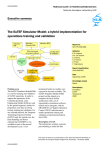
EuroSim Mk5.3 is an engineering simulator framework to support the quick development of hard realtime simulators. EuroSim provides a reconfigurable real-time execution environment with the possibility
of man-in-the-loop and/or hardware-in-the-loop additions. Extensive Graphical User Interfaces assist
the user in constructing, using and analysing real-time simulations, resolving the user from the specialist
software engineering knowledge required to built hard real-time systems.
EuroSim has been developed initially to support the verification of space (sub) systems defined by ESA
programmes of various scales. It’s heritage lies in the development of the European Robotic Arm(ERA)
project where EuroSim was essential in the development and verification of the large symmetrical arm
that can move accross the International Space Station. Up to today, EuroSim installations are still used
around the world to support ERA’s mission preparation, verification and training. After initial development and application for ERA, EuroSim has been succesfully used in the development, verification
and training of the Autonomous Transfer Vehicle (ATV) with multiple installations worldwide. Other
space programs where EuroSim has been applied since are Galileo, Herschel & Planck, Gaia to name a
few major missions. Currently EuroSim has made its way in to other domains as well, with application
in the F-35 Lightning-II Embedded Training program and simulations in support of road tunnel system
verification.
This document contains both the User Guide as well as the Reference Guide documentation and consists
of five volumes. The User Guide volume provides overview and insight in the toolchain as well as introduction and guidance on the development and usage of real-time simulators. This User Guide volume is
recommended reading material for new users of EuroSim. The four Reference Guide volumes provide
in detail information on the GUIs, modelling languages, scripting languages and interface capabilities of
EuroSim. Experienced users will find these Refence volumes more usefull.
Facility administrators are advised to read [OM14], the EuroSim Owner’s Manual. More files and documents that contain information related to EuroSim can be found in the bibliography.
c Copyright Airbus Defence and Space
All rights reserved. Disclosure to third parties of this document or any part thereof, or the use of any
information contained therein for purposes other than provided for by this document, is not permitted,
except with the prior and express written permission of Airbus Defence and Space, PO Box 32070, 2303
DB, Leiden, The Netherlands.
ii
c Airbus Defence and Space
SUM
NLR-EFO-SUM-2
iss: 6 rev: 3
Table of Contents
c Airbus Defence and Space
iii
SUM
NLR-EFO-SUM-2
iss: 6 rev: 3
Table of Contents
v
I
User Guide
1
1
Introduction
1.1 Purpose . . . . . . . .
1.2 Scope . . . . . . . . .
1.3 Where to start . . . . .
1.4 Document conventions
2
3
.
.
.
.
.
.
.
.
.
.
.
.
.
.
.
.
.
.
.
.
.
.
.
.
.
.
.
.
.
.
.
.
.
.
.
.
.
.
.
.
.
.
.
.
.
.
.
.
.
.
.
.
.
.
.
.
.
.
.
.
.
.
.
.
.
.
.
.
.
.
.
.
.
.
.
.
.
.
.
.
.
.
.
.
.
.
.
.
.
.
.
.
.
.
.
.
.
.
.
.
.
.
.
.
.
.
.
.
.
.
.
.
.
.
.
.
3
3
3
4
4
Concepts
2.1 EuroSim simulation lifecycle . . . .
2.2 Simulator elements . . . . . . . . .
2.2.1 Model . . . . . . . . . . . .
2.2.2 Data dictionary . . . . . . .
2.2.3 Schedule . . . . . . . . . .
2.2.4 Simulator . . . . . . . . . .
2.2.5 Scenario . . . . . . . . . . .
2.2.6 Simulation . . . . . . . . .
2.2.7 Test Results . . . . . . . . .
2.2.8 Project . . . . . . . . . . .
2.3 Services and tools . . . . . . . . . .
2.3.1 Project Manager . . . . . .
2.3.2 Model Editor . . . . . . . .
2.3.3 Schedule Editor . . . . . . .
2.3.4 Simulation Controller . . .
2.3.5 Test Analyzer . . . . . . . .
2.4 Application Programmers Interface .
2.5 Version management . . . . . . . .
.
.
.
.
.
.
.
.
.
.
.
.
.
.
.
.
.
.
.
.
.
.
.
.
.
.
.
.
.
.
.
.
.
.
.
.
.
.
.
.
.
.
.
.
.
.
.
.
.
.
.
.
.
.
.
.
.
.
.
.
.
.
.
.
.
.
.
.
.
.
.
.
.
.
.
.
.
.
.
.
.
.
.
.
.
.
.
.
.
.
.
.
.
.
.
.
.
.
.
.
.
.
.
.
.
.
.
.
.
.
.
.
.
.
.
.
.
.
.
.
.
.
.
.
.
.
.
.
.
.
.
.
.
.
.
.
.
.
.
.
.
.
.
.
.
.
.
.
.
.
.
.
.
.
.
.
.
.
.
.
.
.
.
.
.
.
.
.
.
.
.
.
.
.
.
.
.
.
.
.
.
.
.
.
.
.
.
.
.
.
.
.
.
.
.
.
.
.
.
.
.
.
.
.
.
.
.
.
.
.
.
.
.
.
.
.
.
.
.
.
.
.
.
.
.
.
.
.
.
.
.
.
.
.
.
.
.
.
.
.
.
.
.
.
.
.
.
.
.
.
.
.
.
.
.
.
.
.
.
.
.
.
.
.
.
.
.
.
.
.
.
.
.
.
.
.
.
.
.
.
.
.
.
.
.
.
.
.
.
.
.
.
.
.
.
.
.
.
.
.
.
.
.
.
.
.
.
.
.
.
.
.
.
.
.
.
.
.
.
.
.
.
.
.
.
.
.
.
.
.
.
.
.
.
.
.
.
.
.
.
.
.
.
.
.
.
.
.
.
.
.
.
.
.
.
.
.
.
.
.
.
.
.
.
.
.
.
.
.
.
.
.
.
.
.
.
.
.
.
.
.
.
.
.
.
.
.
.
.
.
.
.
.
.
.
.
.
.
.
.
.
.
.
.
.
.
.
.
.
.
.
.
.
.
.
.
.
.
.
.
.
.
.
.
.
.
.
.
.
.
.
.
.
.
.
.
.
.
.
.
.
.
.
.
.
.
.
.
.
.
.
.
.
.
.
.
.
.
.
.
.
.
.
.
.
.
.
.
.
.
.
.
.
.
.
.
.
.
.
.
.
.
.
.
.
.
.
.
.
.
.
.
.
.
.
.
.
.
.
.
.
.
.
.
5
5
6
7
7
7
7
8
8
8
8
9
9
9
10
10
10
10
12
.
.
.
.
.
.
.
.
.
.
.
.
.
.
.
.
.
.
.
.
.
.
13
13
13
13
13
14
14
14
15
16
17
19
21
22
22
23
24
24
24
25
26
28
28
.
.
.
.
.
.
.
.
.
.
.
.
.
.
.
.
.
.
.
.
.
.
.
.
Tutorial
3.1 The case study . . . . . . . . . . . . .
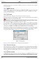
3.2 Starting EuroSim . . . . . . . . . . .
3.2.1 Linux . . . . . . . . . . . . .
3.2.2 Windows . . . . . . . . . . .
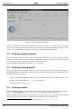
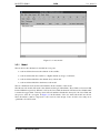
3.3 Creating a project yourself . . . . . .
3.4 Creating a shared project . . . . . . .
3.5 Creating a model . . . . . . . . . . .
3.5.1 Model . . . . . . . . . . . . .
3.5.2 Adding the sub-models . . . .
3.5.3 Adding the source code . . . .
3.5.4 Adding the API headers . . .
3.6 Building the simulator . . . . . . . .
3.7 Creating the schedule . . . . . . . . .
3.7.1 Initializing schedule . . . . .
3.7.2 Executing schedule . . . . . .
3.7.3 Closing the Schedule Editor .
3.8 Creating a simulation definition . . . .
3.8.1 Creating a graphical monitor .
3.8.2 Creating an intervening action
3.8.3 Creating a recorder . . . . . .
3.9 Executing a simulation run . . . . . .
3.10 Analyzing the simulation results . . .
c Airbus Defence and Space
.
.
.
.
.
.
.
.
.
.
.
.
.
.
.
.
.
.
.
.
.
.
.
.
.
.
.
.
.
.
.
.
.
.
.
.
.
.
.
.
.
.
.
.
.
.
.
.
.
.
.
.
.
.
.
.
.
.
.
.
.
.
.
.
.
.
.
.
.
.
.
.
.
.
.
.
.
.
.
.
.
.
.
.
.
.
.
.
.
.
.
.
.
.
.
.
.
.
.
.
.
.
.
.
.
.
.
.
.
.
.
.
.
.
.
.
.
.
.
.
.
.
.
.
.
.
.
.
.
.
.
.
.
.
.
.
.
.
.
.
.
.
.
.
.
.
.
.
.
.
.
.
.
.
.
.
.
.
.
.
.
.
.
.
.
.
.
.
.
.
.
.
.
.
.
.
.
.
.
.
.
.
.
.
.
.
.
.
.
.
.
.
.
.
.
.
.
.
.
.
.
.
.
.
.
.
.
.
.
.
.
.
.
.
.
.
.
.
.
.
.
.
.
.
.
.
.
.
.
.
.
.
.
.
.
.
.
.
.
.
.
.
.
.
.
.
.
.
.
.
.
.
.
.
.
.
.
.
.
.
.
.
.
.
.
.
.
.
.
.
.
.
.
.
.
.
.
.
.
.
.
.
.
.
.
.
.
.
.
.
.
.
.
.
.
.
.
.
.
.
.
.
.
.
.
.
.
.
.
.
.
.
.
.
.
.
.
.
.
.
.
.
.
.
.
.
.
.
.
.
.
.
.
.
.
.
.
.
.
.
.
.
.
.
.
.
.
.
.
.
.
.
.
.
.
.
.
.
.
.
.
.
.
.
.
.
.
.
.
.
.
.
.
.
.
.
.
.
.
.
.
.
.
.
.
.
.
.
.
.
.
.
.
.
.
.
.
.
.
.
.
.
.
.
.
.
.
.
.
.
.
.
.
.
.
.
.
.
.
.
.
.
.
.
.
.
.
.
.
.
.
.
.
.
.
.
.
.
.
.
.
.
.
.
.
.
.
.
.
.
.
.
.
.
.
.
.
.
.
.
.
.
.
.
.
.
.
.
.
.
.
.
.
.
.
.
.
.
.
.
.
.
.
.
.
.
.
.
.
.
.
.
.
.
.
.
.
.
.
.
.
.
.
.
.
.
.
.
.
.
.
.
.
.
.
.
.
.
.
.
.
.
.
.
.
.
.
.
.
.
.
.
.
.
.
.
.
.
.
.
.
.
.
.
.
.
.
.
.
.
.
.
.
.
.
.
.
.
.
.
.
.
.
.
.
.
.
.
.
.
.
.
v
SUM
iss: 6 rev: 3
4
II
5
6
7
vi
NLR-EFO-SUM-2
3.11 Concluding remarks . . . . . . . . . . . . . . . . . . . . . . . . . . . . . . . . . . . . .
30
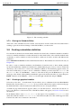
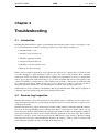
Troubleshooting
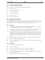
4.1 Introduction . . . . . . . . . . . .
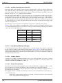
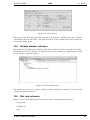
4.2 Daemon Log Inspection . . . . . .
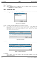
4.3 Core file analysis . . . . . . . . .
4.4 Symbolic Debugging . . . . . . .
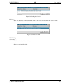
4.5 Scheduler Debugging . . . . . . .
4.6 Tuning Memory options . . . . .
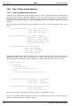
4.7 Tuning Simulator Startup time-out
4.8 Execution Timing analysis . . . .
4.9 Profiling . . . . . . . . . . . . . .
4.10 Coverage analysis . . . . . . . .
31
31
31
32
32
34
34
34
35
35
36
.
.
.
.
.
.
.
.
.
.
.
.
.
.
.
.
.
.
.
.
.
.
.
.
.
.
.
.
.
.
.
.
.
.
.
.
.
.
.
.
.
.
.
.
.
.
.
.
.
.
.
.
.
.
.
.
.
.
.
.
.
.
.
.
.
.
.
.
.
.
.
.
.
.
.
.
.
.
.
.
.
.
.
.
.
.
.
.
.
.
.
.
.
.
.
.
.
.
.
.
.
.
.
.
.
.
.
.
.
.
.
.
.
.
.
.
.
.
.
.
.
.
.
.
.
.
.
.
.
.
.
.
.
.
.
.
.
.
.
.
.
.
.
.
.
.
.
.
.
.
.
.
.
.
.
.
.
.
.
.
.
.
.
.
.
.
.
.
.
.
.
.
.
.
.
.
.
.
.
.
.
.
.
.
.
.
.
.
.
.
.
.
.
.
.
.
.
.
.
.
.
.
.
.
.
.
.
.
.
.
.
.
.
.
.
.
.
.
.
.
.
.
.
.
.
.
.
.
.
.
.
.
.
.
.
.
.
.
.
.
.
.
.
.
.
.
.
.
.
.
.
.
.
.
.
.
.
.
.
.
.
.
.
.
.
.
.
.
.
.
.
.
.
.
.
.
.
.
.
.
.
.
.
.
.
.
.
.
.
.
GUI Reference Guide
Common GUI reference
5.1 GUI conventions in EuroSim
5.2 Mouse buttons . . . . . . . .
5.3 Keyboard shortcuts . . . . .
5.4 Common dialog buttons . . .
5.5 Common toolbar buttons . .
5.6 Common menu items . . . .
5.6.1 File menu . . . . . .
5.6.2 Edit menu . . . . . .
5.6.3 Tools menu . . . . .
5.6.4 Tools:Version menu
5.6.5 Help menu . . . . .
39
.
.
.
.
.
.
.
.
.
.
.
.
.
.
.
.
.
.
.
.
.
.
.
.
.
.
.
.
.
.
.
.
.
.
.
.
.
.
.
.
.
.
.
.
.
.
.
.
.
.
.
.
.
.
.
.
.
.
.
.
.
.
.
.
.
.
.
.
.
.
.
.
.
.
.
.
.
.
.
.
.
.
.
.
.
.
.
.
.
.
.
.
.
.
.
.
.
.
.
.
.
.
.
.
.
.
.
.
.
.
.
.
.
.
.
.
.
.
.
.
.
.
.
.
.
.
.
.
.
.
.
.
.
.
.
.
.
.
.
.
.
.
.
.
.
.
.
.
.
.
.
.
.
.
.
.
.
.
.
.
.
.
.
.
.
.
.
.
.
.
.
.
.
.
.
.
.
.
.
.
.
.
.
.
.
.
.
.
.
.
.
.
.
.
.
.
.
.
.
.
.
.
.
.
.
.
.
.
.
.
.
.
.
.
.
.
.
.
.
.
.
.
.
.
.
.
.
.
.
.
.
.
.
.
.
.
.
.
.
.
.
.
.
.
.
.
.
.
.
.
.
.
.
.
.
.
.
.
.
.
.
.
.
.
.
.
.
.
.
.
.
.
.
.
.
.
.
.
.
.
.
.
.
.
.
.
.
.
.
.
.
.
.
.
.
.
.
.
.
.
.
.
.
.
.
.
.
.
41
41
41
42
42
43
43
43
43
44
44
45
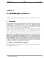
Project Manager reference
6.1 Introduction . . . . . . . . . . . . . .
6.2 Starting the EuroSim Project Manager
6.3 Views in the Project Manager . . . . .
6.4 Menu items . . . . . . . . . . . . . .
6.4.1 File menu . . . . . . . . . . .
6.4.2 Edit menu . . . . . . . . . . .
6.4.3 Insert menu . . . . . . . . . .
6.4.4 Tools menu . . . . . . . . . .
6.4.5 Help menu . . . . . . . . . .
.
.
.
.
.
.
.
.
.
.
.
.
.
.
.
.
.
.
.
.
.
.
.
.
.
.
.
.
.
.
.
.
.
.
.
.
.
.
.
.
.
.
.
.
.
.
.
.
.
.
.
.
.
.
.
.
.
.
.
.
.
.
.
.
.
.
.
.
.
.
.
.
.
.
.
.
.
.
.
.
.
.
.
.
.
.
.
.
.
.
.
.
.
.
.
.
.
.
.
.
.
.
.
.
.
.
.
.
.
.
.
.
.
.
.
.
.
.
.
.
.
.
.
.
.
.
.
.
.
.
.
.
.
.
.
.
.
.
.
.
.
.
.
.
.
.
.
.
.
.
.
.
.
.
.
.
.
.
.
.
.
.
.
.
.
.
.
.
.
.
.
.
.
.
.
.
.
.
.
.
.
.
.
.
.
.
.
.
.
.
.
.
.
.
.
.
.
.
.
.
.
.
.
.
.
.
.
.
.
.
.
.
.
.
.
.
.
.
.
.
.
.
.
.
.
.
.
.
.
.
.
.
.
.
.
.
.
.
.
.
.
.
.
47
47
47
48
49
49
49
50
51
52
.
.
.
.
.
.
.
.
.
.
.
.
53
53
53
54
54
55
55
55
55
55
56
56
58
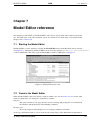
Model Editor reference
7.1 Starting the Model Editor . .
7.2 Views in the Model Editor .
7.2.1 The toolbar . . . . .
7.2.2 The tab pane . . . .
7.2.3 The message pane .
7.2.4 The status bar . . . .
7.3 Objects in the Model Editor .
7.3.1 Root node . . . . . .
7.3.2 Org node . . . . . .
7.3.3 lib node . . . . . . .
7.3.4 File node . . . . . .
7.3.5 Entry nodes . . . . .
.
.
.
.
.
.
.
.
.
.
.
.
.
.
.
.
.
.
.
.
.
.
.
.
.
.
.
.
.
.
.
.
.
.
.
.
.
.
.
.
.
.
.
.
.
.
.
.
.
.
.
.
.
.
.
.
.
.
.
.
.
.
.
.
.
.
.
.
.
.
.
.
.
.
.
.
.
.
.
.
.
.
.
.
.
.
.
.
.
.
.
.
.
.
.
.
.
.
.
.
.
.
.
.
.
.
.
.
.
.
.
.
.
.
.
.
.
.
.
.
.
.
.
.
.
.
.
.
.
.
.
.
.
.
.
.
.
.
.
.
.
.
.
.
.
.
.
.
.
.
.
.
.
.
.
.
.
.
.
.
.
.
.
.
.
.
.
.
.
.
.
.
.
.
.
.
.
.
.
.
.
.
.
.
.
.
.
.
.
.
.
.
.
.
.
.
.
.
.
.
.
.
.
.
.
.
.
.
.
.
.
.
.
.
.
.
.
.
.
.
.
.
.
.
.
.
.
.
.
.
.
.
.
.
.
.
.
.
.
.
.
.
.
.
.
.
.
.
.
.
.
.
.
.
.
.
.
.
.
.
.
.
.
.
.
.
.
.
.
.
.
.
.
.
.
.
.
.
.
.
.
.
.
.
.
.
.
.
.
.
.
.
.
.
.
.
.
.
.
.
.
.
.
.
.
.
.
.
.
.
.
.
.
.
.
.
.
.
.
.
.
.
.
.
.
.
.
.
.
.
.
.
.
.
.
.
.
.
.
.
.
.
.
.
.
.
.
.
.
.
.
.
.
.
.
.
.
.
.
.
.
.
.
.
.
.
.
.
.
.
.
.
.
.
.
.
.
.
.
.
.
.
.
.
.
.
.
.
.
.
.
.
.
.
.
.
.
.
.
.
.
.
.
.
.
.
.
.
.
.
.
.
.
.
.
.
c Airbus Defence and Space
SUM
NLR-EFO-SUM-2
7.4
7.5
7.6
7.7
8
9
7.3.6 Variable nodes . . . . . . . . . . . . .
7.3.7 Object node . . . . . . . . . . . . . . .
7.3.8 Model node . . . . . . . . . . . . . . .
7.3.9 Device node . . . . . . . . . . . . . .
7.3.10 Port node . . . . . . . . . . . . . . . .
7.3.11 Channel node . . . . . . . . . . . . . .
7.3.12 Sequence node . . . . . . . . . . . . .
API Selection . . . . . . . . . . . . . . . . . .
7.4.1 Selecting API Variables and Entrypoints
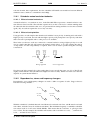
7.4.2 Selection within a sub-model . . . . . .
7.4.3 Selection from two or more sub-models
Menu items . . . . . . . . . . . . . . . . . . .
7.5.1 File menu . . . . . . . . . . . . . . . .
7.5.2 Edit menu . . . . . . . . . . . . . . . .
7.5.3 View menu . . . . . . . . . . . . . . .
7.5.4 Insert menu . . . . . . . . . . . . . . .
7.5.5 API menu . . . . . . . . . . . . . . . .
7.5.6 Tools menu . . . . . . . . . . . . . . .
7.5.7 Tools:SMP2 Tools menu . . . . . . . .
Environment editor and viewer . . . . . . . . .
7.6.1 The environment viewer . . . . . . . .
7.6.2 The environment editor . . . . . . . . .
Configuring File Associations . . . . . . . . .
Model Description Editor reference
8.1 Introduction . . . . . . . . . . . . . . .
8.2 Starting the Model Description Editor .
8.3 Views in the Model Description Editor .
8.4 Objects in the Model Description Editor
8.4.1 Root node . . . . . . . . . . . .
8.4.2 Model node . . . . . . . . . . .
8.4.3 Entry point node . . . . . . . .
8.4.4 Inputs and Outputs group nodes
8.4.5 Input and output nodes . . . . .
8.5 Menu items . . . . . . . . . . . . . . .
8.5.1 File menu . . . . . . . . . . . .
8.5.2 Edit menu . . . . . . . . . . . .
8.5.3 Insert menu . . . . . . . . . . .
8.5.4 Tools menu . . . . . . . . . . .
iss: 6 rev: 3
.
.
.
.
.
.
.
.
.
.
.
.
.
.
.
.
.
.
.
.
.
.
.
.
.
.
.
.
.
.
.
.
.
.
.
.
.
.
.
.
.
.
.
.
.
.
.
.
.
.
.
.
.
.
.
.
.
.
.
.
.
.
.
.
.
.
.
.
.
.
.
.
.
.
.
.
.
.
.
.
.
.
.
.
.
.
.
.
.
.
.
.
.
.
.
.
.
.
.
.
.
.
.
.
.
.
.
.
.
.
.
.
.
.
.
.
.
.
.
.
.
.
.
.
.
.
.
.
.
.
.
.
.
.
.
.
.
.
.
.
.
.
.
.
.
.
.
.
.
.
.
.
.
.
.
.
.
.
.
.
.
.
.
.
.
.
.
.
.
.
.
.
.
.
.
.
.
.
.
.
.
.
.
.
.
.
.
.
.
.
.
.
.
.
.
.
.
.
.
.
.
.
.
.
.
.
.
.
.
.
.
.
.
.
.
.
.
.
.
.
.
.
.
.
.
.
.
.
.
.
.
.
.
.
.
.
.
.
.
.
.
.
.
.
.
.
.
.
.
.
.
.
.
.
.
.
.
.
.
.
.
.
.
.
.
.
.
.
.
.
.
.
.
.
.
.
.
.
.
.
.
.
.
.
.
.
.
.
.
.
.
.
.
.
.
.
.
.
.
.
.
.
.
.
.
.
.
.
.
.
.
.
.
.
.
.
.
.
.
.
.
.
.
.
.
.
.
.
.
.
.
.
.
.
.
.
.
.
.
.
.
.
.
.
.
.
.
.
.
.
.
.
.
.
.
.
.
.
.
.
.
.
.
.
.
.
.
.
.
.
.
.
.
.
.
.
.
.
.
.
.
.
.
.
.
.
.
.
.
.
.
.
.
.
.
.
.
.
.
.
.
.
.
.
.
.
.
.
.
.
.
.
.
.
.
.
.
.
.
.
.
.
.
.
.
.
.
.
.
.
.
.
.
.
.
.
.
.
.
.
.
.
.
.
.
.
.
.
.
.
.
.
.
.
.
.
.
.
.
.
.
.
.
.
.
.
.
.
.
.
.
.
.
.
.
.
.
.
.
.
.
.
.
.
.
.
.
.
.
.
.
.
.
.
.
.
.
.
.
.
.
.
.
.
.
.
58
60
61
61
61
61
61
61
61
61
62
62
62
62
63
63
64
65
68
69
69
70
70
.
.
.
.
.
.
.
.
.
.
.
.
.
.
.
.
.
.
.
.
.
.
.
.
.
.
.
.
.
.
.
.
.
.
.
.
.
.
.
.
.
.
.
.
.
.
.
.
.
.
.
.
.
.
.
.
.
.
.
.
.
.
.
.
.
.
.
.
.
.
.
.
.
.
.
.
.
.
.
.
.
.
.
.
.
.
.
.
.
.
.
.
.
.
.
.
.
.
.
.
.
.
.
.
.
.
.
.
.
.
.
.
.
.
.
.
.
.
.
.
.
.
.
.
.
.
.
.
.
.
.
.
.
.
.
.
.
.
.
.
.
.
.
.
.
.
.
.
.
.
.
.
.
.
.
.
.
.
.
.
.
.
.
.
.
.
.
.
.
.
.
.
.
.
.
.
.
.
.
.
.
.
.
.
.
.
.
.
.
.
.
.
.
.
.
.
.
.
.
.
.
.
.
.
.
.
.
.
.
.
.
.
.
.
.
.
.
.
.
.
.
.
.
.
.
.
.
.
.
.
.
.
.
.
.
.
.
.
.
.
.
.
.
.
.
.
.
.
.
.
.
.
.
.
.
.
.
.
.
.
.
.
.
.
.
.
.
.
.
.
.
.
.
.
.
.
.
.
.
.
.
.
.
.
.
.
.
.
.
.
.
.
.
.
.
.
.
.
.
.
.
.
.
.
.
.
.
.
.
.
.
.
.
.
.
.
.
.
.
.
.
.
.
.
.
.
.
.
.
.
.
.
.
.
.
.
.
.
.
.
.
.
.
.
.
.
.
.
.
.
.
.
.
.
.
.
.
.
.
.
.
.
.
.
71
71
72
73
74
74
75
75
75
75
75
75
75
76
76
Parameter Exchange Editor reference
9.1 Introduction . . . . . . . . . . . . . . . .
9.2 Starting the Parameter Exchange Editor .
9.3 Views in the Parameter Exchange Editor .
9.3.1 Source view . . . . . . . . . . . .
9.3.2 Destination view . . . . . . . . .
9.3.3 Calibration view . . . . . . . . .
9.3.4 Exchange view . . . . . . . . . .
9.4 Objects in the Parameter Exchange Editor
9.4.1 Exchange group node . . . . . . .
9.4.2 Exchange parameter node . . . .
9.5 Menu items . . . . . . . . . . . . . . . .
9.5.1 File menu . . . . . . . . . . . . .
9.5.2 Edit menu . . . . . . . . . . . . .
.
.
.
.
.
.
.
.
.
.
.
.
.
.
.
.
.
.
.
.
.
.
.
.
.
.
.
.
.
.
.
.
.
.
.
.
.
.
.
.
.
.
.
.
.
.
.
.
.
.
.
.
.
.
.
.
.
.
.
.
.
.
.
.
.
.
.
.
.
.
.
.
.
.
.
.
.
.
.
.
.
.
.
.
.
.
.
.
.
.
.
.
.
.
.
.
.
.
.
.
.
.
.
.
.
.
.
.
.
.
.
.
.
.
.
.
.
.
.
.
.
.
.
.
.
.
.
.
.
.
.
.
.
.
.
.
.
.
.
.
.
.
.
.
.
.
.
.
.
.
.
.
.
.
.
.
.
.
.
.
.
.
.
.
.
.
.
.
.
.
.
.
.
.
.
.
.
.
.
.
.
.
.
.
.
.
.
.
.
.
.
.
.
.
.
.
.
.
.
.
.
.
.
.
.
.
.
.
.
.
.
.
.
.
.
.
.
.
.
.
.
.
.
.
.
.
.
.
.
.
.
.
.
.
.
.
.
.
.
.
.
.
.
.
.
.
.
.
.
.
.
.
.
.
.
.
.
.
.
.
.
.
.
.
.
.
.
.
.
.
.
.
.
.
.
.
.
.
.
.
.
.
.
.
.
.
.
.
.
.
.
.
.
.
.
.
.
.
.
.
.
.
.
.
.
.
.
.
.
.
.
.
.
.
.
.
.
.
.
.
.
.
.
.
.
77
77
78
79
79
79
80
80
80
80
80
81
81
81
c Airbus Defence and Space
vii
SUM
iss: 6 rev: 3
9.5.3
9.5.4
Insert menu . . . . . . . . . . . . . . . . . . . . . . . . . . . . . . . . . . . . .
Tools menu . . . . . . . . . . . . . . . . . . . . . . . . . . . . . . . . . . . . .
10 Calibration Editor reference
10.1 Introduction . . . . . . . . . .
10.2 Starting the Calibration Editor
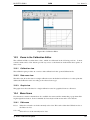
10.3 Views in the Calibration Editor
10.3.1 Calibration view . . .
10.3.2 Data rows view . . . .
10.3.3 Graph view . . . . . .
10.4 Menu Items . . . . . . . . . .
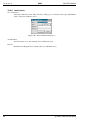
10.4.1 Edit menu . . . . . . .
10.4.2 Insert menu . . . . . .
viii
NLR-EFO-SUM-2
81
81
.
.
.
.
.
.
.
.
.
.
.
.
.
.
.
.
.
.
.
.
.
.
.
.
.
.
.
.
.
.
.
.
.
.
.
.
.
.
.
.
.
.
.
.
.
.
.
.
.
.
.
.
.
.
.
.
.
.
.
.
.
.
.
.
.
.
.
.
.
.
.
.
.
.
.
.
.
.
.
.
.
.
.
.
.
.
.
.
.
.
.
.
.
.
.
.
.
.
.
.
.
.
.
.
.
.
.
.
83
83
84
85
85
85
85
85
85
86
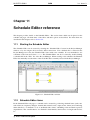
11 Schedule Editor reference
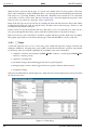
11.1 Starting the Schedule Editor . . . . . . . . . . . . . . . . . . . . .
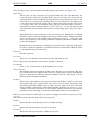
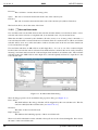
11.2 Schedule Editor items . . . . . . . . . . . . . . . . . . . . . . . . .
11.2.1 Tasks . . . . . . . . . . . . . . . . . . . . . . . . . . . . .
11.2.2 Non real-time tasks . . . . . . . . . . . . . . . . . . . . . .
11.2.3 Mutual exclusions . . . . . . . . . . . . . . . . . . . . . .
11.2.4 Frequency changers . . . . . . . . . . . . . . . . . . . . .
11.2.5 Internal and External events . . . . . . . . . . . . . . . . .
11.2.6 Output events . . . . . . . . . . . . . . . . . . . . . . . . .
11.2.7 Timers . . . . . . . . . . . . . . . . . . . . . . . . . . . .
11.2.8 Flows . . . . . . . . . . . . . . . . . . . . . . . . . . . . .
11.3 Menu options . . . . . . . . . . . . . . . . . . . . . . . . . . . . .
11.3.1 File menu . . . . . . . . . . . . . . . . . . . . . . . . . . .
11.3.2 Edit menu . . . . . . . . . . . . . . . . . . . . . . . . . . .
11.3.3 View menu . . . . . . . . . . . . . . . . . . . . . . . . . .
11.3.4 Insert menu . . . . . . . . . . . . . . . . . . . . . . . . . .
11.3.5 Tools menu . . . . . . . . . . . . . . . . . . . . . . . . . .
11.4 Advanced Scheduler topics . . . . . . . . . . . . . . . . . . . . . .
11.4.1 Scheduler mutual exclusion behavior . . . . . . . . . . . .
11.4.2 Dependencies, stores and frequency changers . . . . . . . .
11.4.3 Frequency changers and mutual exclusive execution of tasks
11.4.4 Timing the output frequency of a frequency changer . . . .
11.4.5 Example of using an output connector for I/O . . . . . . . .
11.4.6 State transitions . . . . . . . . . . . . . . . . . . . . . . . .
11.4.7 Offsets . . . . . . . . . . . . . . . . . . . . . . . . . . . .
11.4.8 Scheduling the action manager (ACTION MGR) . . . . . .
11.4.9 Clock types . . . . . . . . . . . . . . . . . . . . . . . . . .
.
.
.
.
.
.
.
.
.
.
.
.
.
.
.
.
.
.
.
.
.
.
.
.
.
.
.
.
.
.
.
.
.
.
.
.
.
.
.
.
.
.
.
.
.
.
.
.
.
.
.
.
.
.
.
.
.
.
.
.
.
.
.
.
.
.
.
.
.
.
.
.
.
.
.
.
.
.
.
.
.
.
.
.
.
.
.
.
.
.
.
.
.
.
.
.
.
.
.
.
.
.
.
.
.
.
.
.
.
.
.
.
.
.
.
.
.
.
.
.
.
.
.
.
.
.
.
.
.
.
.
.
.
.
.
.
.
.
.
.
.
.
.
.
.
.
.
.
.
.
.
.
.
.
.
.
.
.
.
.
.
.
.
.
.
.
.
.
.
.
.
.
.
.
.
.
.
.
.
.
.
.
.
.
.
.
.
.
.
.
.
.
.
.
.
.
.
.
.
.
.
.
.
.
.
.
.
.
.
.
.
.
.
.
.
.
.
.
.
.
.
.
.
.
.
.
.
.
.
.
.
.
.
.
.
.
.
.
.
.
.
.
.
.
.
.
.
.
.
.
.
.
.
.
.
.
.
.
.
.
.
.
.
.
.
.
.
.
.
.
.
.
.
.
.
.
.
.
.
.
.
.
.
.
.
.
87
87
87
88
90
91
91
92
92
92
93
93
93
93
93
94
95
98
99
99
100
101
102
103
103
104
104
12 Simulation Controller reference
12.1 Starting the Simulation Controller . . .
12.2 Input Files of the Simulation Controller
12.2.1 Initial Condition . . . . . . . .
12.2.2 Script Action . . . . . . . . . .
12.2.3 Stimulus Action . . . . . . . .
12.2.4 Recorder Action . . . . . . . .
12.2.5 Monitors . . . . . . . . . . . .
12.3 Windows of the Simulation Controller .
12.3.1 The toolbar . . . . . . . . . . .
12.3.2 The tab pane . . . . . . . . . .
12.3.3 The message pane . . . . . . .
.
.
.
.
.
.
.
.
.
.
.
.
.
.
.
.
.
.
.
.
.
.
.
.
.
.
.
.
.
.
.
.
.
.
.
.
.
.
.
.
.
.
.
.
.
.
.
.
.
.
.
.
.
.
.
.
.
.
.
.
.
.
.
.
.
.
.
.
.
.
.
.
.
.
.
.
.
.
.
.
.
.
.
.
.
.
.
.
.
.
.
.
.
.
.
.
.
.
.
.
.
.
.
.
.
.
.
.
.
.
.
.
.
.
.
.
.
.
.
.
.
107
107
107
108
109
110
110
110
111
111
112
112
.
.
.
.
.
.
.
.
.
.
.
.
.
.
.
.
.
.
.
.
.
.
.
.
.
.
.
.
.
.
.
.
.
.
.
.
.
.
.
.
.
.
.
.
.
.
.
.
.
.
.
.
.
.
.
.
.
.
.
.
.
.
.
.
.
.
.
.
.
.
.
.
.
.
.
.
.
.
.
.
.
.
.
.
.
.
.
.
.
.
.
.
.
.
.
.
.
.
.
.
.
.
.
.
.
.
.
.
.
.
.
.
.
.
.
.
.
.
.
.
.
.
.
.
.
.
.
.
.
.
.
.
.
.
.
.
.
.
.
.
.
.
.
.
.
.
.
.
.
.
.
.
.
.
.
.
.
.
.
.
.
.
.
.
.
.
.
.
.
.
.
.
.
.
.
.
.
.
.
.
.
.
.
.
.
.
.
.
.
.
.
.
.
.
.
.
.
.
.
.
.
.
.
.
.
.
.
.
.
.
.
.
.
.
.
.
.
.
.
.
.
.
.
.
.
.
.
.
.
.
.
.
.
.
.
.
.
.
.
.
.
.
.
.
.
.
.
.
.
.
.
.
.
.
.
.
.
.
.
.
.
.
.
.
.
.
.
.
.
.
.
.
.
.
.
.
.
.
.
.
.
.
.
.
.
.
.
.
.
.
.
.
.
.
.
.
.
.
.
.
.
.
.
.
.
.
.
.
.
.
.
.
.
.
.
.
.
.
.
.
.
.
.
.
.
.
.
.
.
.
.
.
.
.
.
.
c Airbus Defence and Space
NLR-EFO-SUM-2
SUM
iss: 6 rev: 3
12.3.4 The status bar . . . . . . . . . . .
12.4 Output files of the Simulation Controller .
12.5 Dictionary Browser . . . . . . . . . . . .
12.6 Menu Items . . . . . . . . . . . . . . . .
12.6.1 Edit menu . . . . . . . . . . . . .
12.6.2 View menu . . . . . . . . . . . .
12.6.3 Insert menu . . . . . . . . . . . .
12.6.4 Server menu . . . . . . . . . . .
12.6.5 Control menu . . . . . . . . . . .
12.6.6 Tools menu . . . . . . . . . . . .
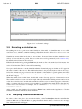
12.7 Input Files tab page . . . . . . . . . . . .
12.7.1 Menu items . . . . . . . . . . . .
12.7.2 Context menus . . . . . . . . . .
12.7.3 Data Dictionary Aliases . . . . .
12.7.4 Initial Condition Editor . . . . . .
12.8 Schedule tab page . . . . . . . . . . . . .
12.8.1 Debugging Concepts . . . . . . .
12.8.2 Debug Control objects . . . . . .
12.8.3 Menu items . . . . . . . . . . . .
12.8.4 External debugging facilities . . .
12.8.5 Timing analysis . . . . . . . . . .
12.9 API tab page . . . . . . . . . . . . . . .
12.10Scenario tab page . . . . . . . . . . . . .
12.10.1 Menu items . . . . . . . . . . . .
12.10.2 Context menus . . . . . . . . . .
12.10.3 Action Editor . . . . . . . . . . .
12.11MMI tab page . . . . . . . . . . . . . . .
12.11.1 Menu items . . . . . . . . . . . .
12.11.2 Context menus . . . . . . . . . .
12.11.3 Action Button Editor . . . . . . .
12.11.4 Monitor Editor . . . . . . . . . .
12.11.5 User-Defined Monitors (Plugins) .
12.12Message tab pane . . . . . . . . . . . . .
12.12.1 Editing message tab properties . .
12.12.2 Menu Items . . . . . . . . . . . .
12.12.3 Context menus . . . . . . . . . .
12.12.4 User defined message types . . .
.
.
.
.
.
.
.
.
.
.
.
.
.
.
.
.
.
.
.
.
.
.
.
.
.
.
.
.
.
.
.
.
.
.
.
.
.
.
.
.
.
.
.
.
.
.
.
.
.
.
.
.
.
.
.
.
.
.
.
.
.
.
.
.
.
.
.
.
.
.
.
.
.
.
.
.
.
.
.
.
.
.
.
.
.
.
.
.
.
.
.
.
.
.
.
.
.
.
.
.
.
.
.
.
.
.
.
.
.
.
.
.
.
.
.
.
.
.
.
.
.
.
.
.
.
.
.
.
.
.
.
.
.
.
.
.
.
.
.
.
.
.
.
.
.
.
.
.
.
.
.
.
.
.
.
.
.
.
.
.
.
.
.
.
.
.
.
.
.
.
.
.
.
.
.
.
.
.
.
.
.
.
.
.
.
.
.
.
.
.
.
.
.
.
.
.
.
.
.
.
.
.
.
.
.
.
.
.
.
.
.
.
.
.
.
.
.
.
.
.
.
.
.
.
.
.
.
.
.
.
.
.
.
.
.
.
.
.
.
.
.
.
.
.
.
.
.
.
.
.
.
.
.
.
.
.
.
.
.
.
.
.
.
.
.
.
.
.
.
.
.
.
.
.
.
.
.
.
.
.
.
.
.
.
.
.
.
.
.
.
.
.
.
.
.
.
.
.
.
.
.
.
.
.
.
.
.
.
.
.
.
.
.
.
.
.
.
.
.
.
.
.
.
.
.
.
.
.
.
.
.
.
.
.
.
.
.
.
.
.
.
.
.
.
.
.
.
.
.
.
.
.
.
.
.
.
.
.
.
.
.
.
.
.
.
.
.
.
.
.
.
.
.
.
.
.
.
.
.
.
.
.
.
.
.
.
.
.
.
.
.
.
.
.
.
.
.
.
.
.
.
.
.
.
.
.
.
.
.
.
.
.
.
.
.
.
.
.
.
.
.
.
.
.
.
.
.
.
.
.
.
.
.
.
.
.
.
.
.
.
.
.
.
.
.
.
.
.
.
.
.
.
.
.
.
.
.
.
.
.
.
.
.
.
.
.
.
.
.
.
.
.
.
.
.
.
.
.
.
.
.
.
.
.
.
.
.
.
.
.
.
.
.
.
.
.
.
.
.
.
.
.
.
.
.
.
.
.
.
.
.
.
.
.
.
.
.
.
.
.
.
.
.
.
.
.
.
.
.
.
.
.
.
.
.
.
.
.
.
.
.
.
.
.
.
.
.
.
.
.
.
.
.
.
.
.
.
.
.
.
.
.
.
.
.
.
.
.
.
.
.
.
.
.
.
.
.
.
.
.
.
.
.
.
.
.
.
.
.
.
.
.
.
.
.
.
.
.
.
.
.
.
.
.
.
.
.
.
.
.
.
.
.
.
.
.
.
.
.
.
.
.
.
.
.
.
.
.
.
.
.
.
.
.
.
.
.
.
.
.
.
.
.
.
.
.
.
.
.
.
.
.
.
.
.
.
.
.
.
.
.
.
.
.
.
.
.
.
.
.
.
.
.
.
.
.
.
.
.
.
.
.
.
.
.
.
.
.
.
.
.
.
.
.
.
.
.
.
.
.
.
.
.
.
.
.
.
.
.
.
.
.
.
.
.
.
.
.
.
.
.
.
.
.
.
.
.
.
.
.
.
.
.
.
.
.
.
.
.
.
.
.
.
.
.
.
.
.
.
.
.
.
.
.
.
.
.
.
.
.
.
.
.
.
.
.
.
.
.
.
.
.
.
.
.
.
.
.
.
.
.
.
.
.
.
.
.
.
.
.
.
.
.
.
.
.
.
.
.
.
.
.
.
.
.
.
.
.
.
.
.
.
.
.
.
.
.
.
.
.
.
.
.
.
.
.
.
.
.
.
.
.
.
.
.
.
.
.
.
.
.
.
.
.
.
.
.
.
.
.
.
.
.
.
.
.
.
.
.
.
.
.
.
.
.
.
.
.
.
.
.
.
.
.
.
.
.
.
.
.
.
.
.
.
.
.
.
.
.
.
.
.
.
.
.
.
.
.
.
.
.
.
.
.
.
.
.
.
.
.
.
.
.
.
.
.
.
.
.
.
.
.
.
.
.
113
113
114
114
114
115
115
117
118
120
123
123
124
125
125
126
127
127
128
128
129
131
131
133
135
136
141
142
142
143
144
146
148
149
149
149
150
13 Test Analyzer reference
13.1 Starting the Test Analyzer . . . . . . . .
13.2 Using the Test Analyzer . . . . . . . . . .
13.3 Test Analyzer main window . . . . . . .
13.3.1 Opening a plot file . . . . . . . .
13.3.2 Importing old plot definition files
13.3.3 Selecting the test results file . . .
13.3.4 Using recorder files . . . . . . . .
13.3.5 Creating a new plot . . . . . . . .
13.3.6 Changing a plot . . . . . . . . . .
13.3.7 Showing and printing plots . . . .
13.4 Plot properties reference . . . . . . . . .
13.4.1 General plot properties . . . . . .
13.4.2 Curve editor reference . . . . . .
13.4.3 Axes properties . . . . . . . . . .
.
.
.
.
.
.
.
.
.
.
.
.
.
.
.
.
.
.
.
.
.
.
.
.
.
.
.
.
.
.
.
.
.
.
.
.
.
.
.
.
.
.
.
.
.
.
.
.
.
.
.
.
.
.
.
.
.
.
.
.
.
.
.
.
.
.
.
.
.
.
.
.
.
.
.
.
.
.
.
.
.
.
.
.
.
.
.
.
.
.
.
.
.
.
.
.
.
.
.
.
.
.
.
.
.
.
.
.
.
.
.
.
.
.
.
.
.
.
.
.
.
.
.
.
.
.
.
.
.
.
.
.
.
.
.
.
.
.
.
.
.
.
.
.
.
.
.
.
.
.
.
.
.
.
.
.
.
.
.
.
.
.
.
.
.
.
.
.
.
.
.
.
.
.
.
.
.
.
.
.
.
.
.
.
.
.
.
.
.
.
.
.
.
.
.
.
.
.
.
.
.
.
.
.
.
.
.
.
.
.
.
.
.
.
.
.
.
.
.
.
.
.
.
.
.
.
.
.
.
.
.
.
.
.
.
.
.
.
.
.
.
.
.
.
.
.
.
.
.
.
.
.
.
.
.
.
.
.
.
.
.
.
.
.
.
.
.
.
.
.
.
.
.
.
.
.
.
.
.
.
.
.
.
.
.
.
.
.
.
.
.
.
.
.
.
.
.
.
.
.
.
.
.
.
.
.
.
.
.
.
.
.
.
.
.
.
.
.
.
.
.
.
.
.
.
.
.
.
.
.
.
.
.
.
.
.
.
.
.
.
.
.
.
.
.
.
.
.
.
.
151
151
151
151
152
153
153
153
153
154
154
154
155
155
156
c Airbus Defence and Space
ix
SUM
iss: 6 rev: 3
NLR-EFO-SUM-2
13.5 Variable browser reference . . . . . . . . . . . . . . . .
13.6 Plot view reference . . . . . . . . . . . . . . . . . . . .
13.7 Menu items reference . . . . . . . . . . . . . . . . . . .
13.7.1 File menu . . . . . . . . . . . . . . . . . . . . .
13.7.2 Edit menu . . . . . . . . . . . . . . . . . . . . .
13.7.3 View menu . . . . . . . . . . . . . . . . . . . .
13.7.4 Plot menu . . . . . . . . . . . . . . . . . . . . .
13.7.5 Curve menu . . . . . . . . . . . . . . . . . . . .
13.7.6 Tools menu . . . . . . . . . . . . . . . . . . . .
13.7.7 Help menu . . . . . . . . . . . . . . . . . . . .
13.8 Toolbar reference . . . . . . . . . . . . . . . . . . . . .
13.9 Using User Defined Functions . . . . . . . . . . . . . .
13.9.1 The function editor . . . . . . . . . . . . . . . .
13.9.2 Format and Validation . . . . . . . . . . . . . .
13.10PV-WAVE interface . . . . . . . . . . . . . . . . . . . .
13.10.1 PV-WAVE Operators and Functions . . . . . . .
13.10.2 PV-WAVE Variables . . . . . . . . . . . . . . .
13.10.3 Accessing recorded data . . . . . . . . . . . . .
13.10.4 Examples of using PV-WAVE commands directly
13.10.5 User defined functions . . . . . . . . . . . . . .
13.10.6 PV-WAVE help . . . . . . . . . . . . . . . . . .
13.10.7 The PV-WAVE process . . . . . . . . . . . . .
13.11gnuplot interface . . . . . . . . . . . . . . . . . . . . .
13.11.1 gnuplot operators and functions . . . . . . . . .
13.11.2 Accessing recorded data . . . . . . . . . . . . .
13.11.3 gnuplot help . . . . . . . . . . . . . . . . . . .
III
x
.
.
.
.
.
.
.
.
.
.
.
.
.
.
.
.
.
.
.
.
.
.
.
.
.
.
.
.
.
.
.
.
.
.
.
.
.
.
.
.
.
.
.
.
.
.
.
.
.
.
.
.
.
.
.
.
.
.
.
.
.
.
.
.
.
.
.
.
.
.
.
.
.
.
.
.
.
.
.
.
.
.
.
.
.
.
.
.
.
.
.
.
.
.
.
.
.
.
.
.
.
.
.
.
.
.
.
.
.
.
.
.
.
.
.
.
.
.
.
.
.
.
.
.
.
.
.
.
.
.
.
.
.
.
.
.
.
.
.
.
.
.
.
.
.
.
.
.
.
.
.
.
.
.
.
.
.
.
.
.
.
.
.
.
.
.
.
.
.
.
.
.
.
.
.
.
.
.
.
.
.
.
.
.
.
.
.
.
.
.
.
.
.
.
.
.
.
.
.
.
.
.
.
.
.
.
.
.
.
.
.
.
.
.
.
.
.
.
.
.
.
.
.
.
.
.
.
.
.
.
.
.
.
.
.
.
.
.
.
.
.
.
.
.
.
.
.
.
.
.
.
.
.
.
.
.
.
.
.
.
.
.
.
.
.
.
.
.
.
.
.
.
.
.
.
.
.
.
.
.
.
.
.
.
.
.
.
.
.
.
.
.
.
.
.
.
.
.
.
.
.
.
.
.
.
.
.
.
.
.
.
.
.
.
.
.
.
.
.
.
.
.
.
.
.
.
.
.
.
.
.
.
.
.
.
.
.
.
.
.
.
.
.
.
.
.
.
.
.
.
.
.
.
.
.
.
.
.
.
.
.
.
.
.
.
.
.
.
.
.
.
.
.
.
.
.
.
.
.
.
.
.
.
.
.
.
.
.
.
.
.
.
.
.
.
.
.
.
.
.
.
.
.
.
.
.
.
.
.
.
.
.
.
.
.
.
.
.
.
.
.
.
.
.
.
.
.
.
.
.
.
.
.
.
.
.
.
.
.
.
.
157
157
158
158
159
159
159
160
160
160
160
160
161
161
162
162
163
163
163
165
165
165
165
165
166
166
Modelling Reference Guide
167
14 C, Fortran, Ada interface reference
14.1 Introduction . . . . . . . . . . .
14.2 Setup procedure . . . . . . . . .
14.3 Publication interface . . . . . .
14.3.1 API Header . . . . . . .
14.3.2 Publication functions . .
14.4 Service interface . . . . . . . .
14.4.1 Usage in C . . . . . . .
14.4.2 Usage in Fortran . . . .
14.4.3 Usage in Ada-95 . . . .
14.4.4 Description of functions
14.5 Limitations . . . . . . . . . . .
14.5.1 Generial limitations . . .
14.5.2 C limitations . . . . . .
14.5.3 Fortran limitations . . .
14.5.4 Ada-95 limitations . . .
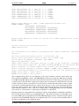
14.6 Example API header . . . . . .
14.6.1 C Example . . . . . . .
14.6.2 Ada-95 Example . . . .
169
169
169
170
170
171
172
172
175
176
179
184
184
185
185
185
186
186
187
.
.
.
.
.
.
.
.
.
.
.
.
.
.
.
.
.
.
.
.
.
.
.
.
.
.
.
.
.
.
.
.
.
.
.
.
.
.
.
.
.
.
.
.
.
.
.
.
.
.
.
.
.
.
.
.
.
.
.
.
.
.
.
.
.
.
.
.
.
.
.
.
.
.
.
.
.
.
.
.
.
.
.
.
.
.
.
.
.
.
.
.
.
.
.
.
.
.
.
.
.
.
.
.
.
.
.
.
.
.
.
.
.
.
.
.
.
.
.
.
.
.
.
.
.
.
.
.
.
.
.
.
.
.
.
.
.
.
.
.
.
.
.
.
.
.
.
.
.
.
.
.
.
.
.
.
.
.
.
.
.
.
.
.
.
.
.
.
.
.
.
.
.
.
.
.
.
.
.
.
.
.
.
.
.
.
.
.
.
.
.
.
.
.
.
.
.
.
.
.
.
.
.
.
.
.
.
.
.
.
.
.
.
.
.
.
.
.
.
.
.
.
.
.
.
.
.
.
.
.
.
.
.
.
.
.
.
.
.
.
.
.
.
.
.
.
.
.
.
.
.
.
.
.
.
.
.
.
.
.
.
.
.
.
.
.
.
.
.
.
.
.
.
.
.
.
.
.
.
.
.
.
.
.
.
.
.
.
.
.
.
.
.
.
.
.
.
.
.
.
.
.
.
.
.
.
.
.
.
.
.
.
.
.
.
.
.
.
.
.
.
.
.
.
.
.
.
.
.
.
.
.
.
.
.
.
.
.
.
.
.
.
.
.
.
.
.
.
.
.
.
.
.
.
.
.
.
.
.
.
.
.
.
.
.
.
.
.
.
.
.
.
.
.
.
.
.
.
.
.
.
.
.
.
.
.
.
.
.
.
.
.
.
.
.
.
.
.
.
.
.
.
.
.
.
.
.
.
.
.
.
.
.
.
.
.
.
.
.
.
.
.
.
.
.
.
.
.
.
.
.
.
.
.
.
.
.
.
.
.
.
.
.
.
.
.
.
.
.
.
.
.
.
.
.
.
.
.
.
.
.
.
.
.
.
.
.
.
.
.
.
.
.
.
.
.
.
.
.
.
.
.
.
.
.
.
.
.
.
.
.
.
.
.
.
.
.
.
.
.
.
.
.
.
.
.
.
.
.
.
.
.
.
.
.
.
.
.
.
.
.
.
.
.
.
.
.
.
.
.
.
.
.
.
.
.
.
.
.
.
c Airbus Defence and Space
SUM
NLR-EFO-SUM-2
iss: 6 rev: 3
15 C++ interface reference
15.1 Introduction . . . . . . . . . . . . . . . . . . . .
15.2 Setup procedure . . . . . . . . . . . . . . . . . .
15.3 Publication interface . . . . . . . . . . . . . . .
15.3.1 Standard publication interface . . . . . .
15.3.2 Adding publication details . . . . . . . .
15.3.3 Typed publication . . . . . . . . . . . . .
15.3.4 Publication configuration and debugging
15.4 Service interface . . . . . . . . . . . . . . . . .
15.5 Supported data types . . . . . . . . . . . . . . .
15.5.1 Basic types and arrays . . . . . . . . . .
15.5.2 Container Types . . . . . . . . . . . . .
15.6 Simulator Integration interface . . . . . . . . . .
15.7 Error Injection interface . . . . . . . . . . . . . .
15.8 UML support . . . . . . . . . . . . . . . . . . .
15.8.1 Overview . . . . . . . . . . . . . . . . .
15.8.2 Architecture and Transformation . . . . .
15.8.3 Design and Generation . . . . . . . . . .
15.8.4 Simulator Building . . . . . . . . . . . .
15.8.5 Resources . . . . . . . . . . . . . . . . .
15.9 Tips, Tricks and Guidelines . . . . . . . . . . . .
15.9.1 Low level publication interface . . . . . .
15.9.2 Portability . . . . . . . . . . . . . . . . .
15.9.3 Stubbing . . . . . . . . . . . . . . . . .
15.9.4 Usage of Eclipse . . . . . . . . . . . . .
.
.
.
.
.
.
.
.
.
.
.
.
.
.
.
.
.
.
.
.
.
.
.
.
16 Simulation Model Portability 2 reference
16.1 SMP2 tools in the EuroSim Environment . . . . . .
16.2 Using SMP2 in the EuroSim Environment . . . . .
16.2.1 The Model Editor’s SMP2 import facilities
16.2.2 The SMP2 schedule import facilities . . . .
16.2.3 The Simulation Controller and SMP2 . . .
17 Java interface reference
17.1 Introduction . . . . .
17.2 Setup procedure . . .
17.3 Publication interface
17.4 Service interface . .
17.5 Supported data types
.
.
.
.
.
.
.
.
.
.
.
.
.
.
.
.
.
.
.
.
.
.
.
.
.
.
.
.
.
.
.
.
.
.
.
.
.
.
.
.
.
.
.
.
.
.
.
.
.
.
.
.
.
.
.
.
.
.
.
.
.
.
.
.
.
18 Simulator Integration Support library reference
18.1 Introduction . . . . . . . . . . . . . . . . . .
18.2 Files . . . . . . . . . . . . . . . . . . . . . .
18.3 Use case example . . . . . . . . . . . . . . .
18.3.1 Model files . . . . . . . . . . . . . .
18.3.2 Model Description file . . . . . . . .
18.3.3 Parameter Exchange file . . . . . . .
18.3.4 Specifying the schedule . . . . . . .
18.3.5 Concluding remarks . . . . . . . . .
18.4 Initial values . . . . . . . . . . . . . . . . . .
18.5 Build process . . . . . . . . . . . . . . . . .
c Airbus Defence and Space
.
.
.
.
.
.
.
.
.
.
.
.
.
.
.
.
.
.
.
.
.
.
.
.
.
.
.
.
.
.
.
.
.
.
.
.
.
.
.
.
.
.
.
.
.
.
.
.
.
.
.
.
.
.
.
.
.
.
.
.
.
.
.
.
.
.
.
.
.
.
.
.
.
.
.
.
.
.
.
.
.
.
.
.
.
.
.
.
.
.
.
.
.
.
.
.
.
.
.
.
.
.
.
.
.
.
.
.
.
.
.
.
.
.
.
.
.
.
.
.
.
.
.
.
.
.
.
.
.
.
.
.
.
.
.
.
.
.
.
.
.
.
.
.
.
.
.
.
.
.
.
.
.
.
.
.
.
.
.
.
.
.
.
.
.
.
.
.
.
.
.
.
.
.
.
.
.
.
.
.
.
.
.
.
.
.
.
.
.
.
.
.
.
.
.
.
.
.
.
.
.
.
.
.
.
.
.
.
.
.
.
.
.
.
.
.
.
.
.
.
.
.
.
.
.
.
.
.
.
.
.
.
.
.
.
.
.
.
.
.
.
.
.
.
.
.
.
.
.
.
.
.
.
.
.
.
.
.
.
.
.
.
.
.
.
.
.
.
.
.
.
.
.
.
.
.
.
.
.
.
.
.
.
.
.
.
.
.
.
.
.
.
.
.
.
.
.
.
.
.
.
.
.
.
.
.
.
.
.
.
.
.
.
.
.
.
.
.
.
.
.
.
.
.
.
.
.
.
.
.
.
.
.
.
.
.
.
.
.
.
.
.
.
.
.
.
.
.
.
.
.
.
.
.
.
.
.
.
.
.
.
.
.
.
.
.
.
.
.
.
.
.
.
.
.
.
.
.
.
.
.
.
.
.
.
.
.
.
.
.
.
.
.
.
.
.
.
.
.
.
.
.
.
.
.
.
.
.
.
.
.
.
.
.
.
.
.
.
.
.
.
.
.
.
.
.
.
.
.
.
.
.
.
.
.
.
.
.
.
.
.
.
.
.
.
.
.
.
.
.
.
.
.
.
.
.
.
.
.
.
.
.
.
.
.
.
.
.
.
.
.
.
.
.
.
.
.
.
.
.
.
.
.
.
.
.
.
.
.
.
.
.
.
.
.
.
.
.
.
.
.
.
.
.
.
.
.
.
.
.
.
.
.
.
.
.
.
.
.
.
.
.
.
.
.
.
.
.
.
.
.
.
.
.
.
.
.
.
.
.
.
.
.
.
.
.
.
.
.
.
.
.
.
.
.
.
.
.
.
.
.
.
.
.
.
.
.
.
.
.
.
.
.
.
.
.
.
.
.
.
.
.
.
.
.
.
.
.
.
.
.
.
.
.
.
.
.
.
.
.
.
.
.
.
.
.
.
.
.
.
.
.
.
.
.
.
.
.
.
.
.
.
.
.
.
.
.
.
.
.
.
.
.
.
.
.
.
.
.
.
.
.
.
.
.
.
.
.
.
.
.
.
.
.
.
.
.
.
.
.
.
.
.
.
.
.
.
.
.
.
.
.
.
.
.
.
.
.
.
.
.
.
.
.
.
.
.
.
.
.
.
.
.
.
.
.
.
.
.
.
.
.
.
.
.
.
.
.
.
.
.
.
.
.
.
.
.
.
.
.
.
.
.
.
.
.
.
.
.
.
.
.
.
.
.
.
.
.
.
.
.
.
.
.
.
.
.
.
.
.
.
.
.
.
.
.
.
.
.
.
.
.
.
.
.
.
.
.
.
.
.
.
.
.
.
.
.
.
.
.
.
.
.
.
.
.
.
.
.
.
.
.
.
.
.
.
.
.
.
.
.
.
.
.
.
.
.
.
.
.
.
.
.
.
.
.
.
.
.
.
.
.
.
.
.
.
.
.
.
.
.
.
.
.
.
.
.
.
.
.
.
.
.
.
.
.
.
.
.
.
.
.
.
.
.
.
.
.
.
.
.
.
.
.
.
.
.
.
.
.
.
.
.
.
.
.
.
.
.
.
.
.
.
.
.
.
.
.
.
.
.
.
.
.
.
.
.
.
.
.
.
.
.
.
.
191
191
192
194
194
196
197
198
199
200
200
201
203
206
208
208
209
210
212
213
214
214
215
216
216
.
.
.
.
.
219
219
220
221
225
226
.
.
.
.
.
227
227
227
228
229
231
.
.
.
.
.
.
.
.
.
.
235
235
235
235
235
236
237
238
240
240
241
xi
SUM
iss: 6 rev: 3
NLR-EFO-SUM-2
19 Error Injection library reference
19.1 Introduction . . . . . . . . . . . . . . . . . . . .
19.2 Defining the error injection function . . . . . . .
19.3 Defining the variables affected by error injection .
19.4 Build process . . . . . . . . . . . . . . . . . . .
.
.
.
.
.
.
.
.
.
.
.
.
.
.
.
.
.
.
.
.
.
.
.
.
.
.
.
.
.
.
.
.
.
.
.
.
.
.
.
.
.
.
.
.
.
.
.
.
.
.
.
.
.
.
.
.
.
.
.
.
.
.
.
.
.
.
.
.
.
.
.
.
.
.
.
.
.
.
.
.
.
.
.
.
243
243
243
245
246
20 Calibration Library reference
247
20.1 Introduction . . . . . . . . . . . . . . . . . . . . . . . . . . . . . . . . . . . . . . . . . 247
20.2 Application Programmers Interface . . . . . . . . . . . . . . . . . . . . . . . . . . . . . 247
IV
xii
Scripting Reference Guide
249
21 Mission Definition Language reference
21.1 MDL primer . . . . . . . . . . . . . . . . . . . . . . . . .
21.2 MDL constants, types, variables, operators and expressions
21.3 Control Flow . . . . . . . . . . . . . . . . . . . . . . . .
21.4 Functions . . . . . . . . . . . . . . . . . . . . . . . . . .
21.5 Input/Output and Simulator Control . . . . . . . . . . . .
21.6 MDL Built-in functions and commands . . . . . . . . . .
21.7 MDL syntax . . . . . . . . . . . . . . . . . . . . . . . . .
.
.
.
.
.
.
.
.
.
.
.
.
.
.
.
.
.
.
.
.
.
.
.
.
.
.
.
.
.
.
.
.
.
.
.
.
.
.
.
.
.
.
.
.
.
.
.
.
.
.
.
.
.
.
.
.
.
.
.
.
.
.
.
.
.
.
.
.
.
.
.
.
.
.
.
.
.
.
.
.
.
.
.
.
.
.
.
.
.
.
.
.
.
.
.
.
.
.
.
.
.
.
.
.
.
.
.
.
.
.
.
.
251
251
253
254
255
256
257
262
22 Perl batch reference
22.1 Introduction . . . . . . . . . . . . . . .
22.2 Conversion utility for event-probe users
22.3 Starting the interactive batch shell . . .
22.4 Batch utility modules . . . . . . . . . .
22.4.1 EuroSim::Session module . . .
22.4.2 EuroSim::SimDef module . . .
22.4.3 EuroSim::MDL module . . . .
22.4.4 EuroSim::Dict module . . . . .
22.4.5 EuroSim::InitCond module . . .
22.4.6 EuroSim::Link module . . . . .
22.4.7 EuroSim::Conn module . . . .
22.5 Extending the batch utility . . . . . . .
22.6 Example . . . . . . . . . . . . . . . . .
22.7 Useful command line utilities . . . . . .
22.7.1 efoList . . . . . . . . . . . . .
22.7.2 efoKill . . . . . . . . . . . . .
.
.
.
.
.
.
.
.
.
.
.
.
.
.
.
.
.
.
.
.
.
.
.
.
.
.
.
.
.
.
.
.
.
.
.
.
.
.
.
.
.
.
.
.
.
.
.
.
.
.
.
.
.
.
.
.
.
.
.
.
.
.
.
.
.
.
.
.
.
.
.
.
.
.
.
.
.
.
.
.
.
.
.
.
.
.
.
.
.
.
.
.
.
.
.
.
.
.
.
.
.
.
.
.
.
.
.
.
.
.
.
.
.
.
.
.
.
.
.
.
.
.
.
.
.
.
.
.
.
.
.
.
.
.
.
.
.
.
.
.
.
.
.
.
.
.
.
.
.
.
.
.
.
.
.
.
.
.
.
.
.
.
.
.
.
.
.
.
.
.
.
.
.
.
.
.
.
.
.
.
.
.
.
.
.
.
.
.
.
.
.
.
.
.
.
.
.
.
.
.
.
.
.
.
.
.
.
.
.
.
.
.
.
.
.
.
.
.
.
.
.
.
.
.
.
.
.
.
.
.
.
.
.
.
.
.
.
.
.
.
.
.
.
.
.
.
.
.
.
.
.
.
.
.
.
.
.
.
.
.
.
.
.
.
.
.
.
.
.
.
.
.
.
.
.
.
.
.
.
.
.
.
.
.
.
.
.
.
.
.
.
.
.
.
.
.
.
.
.
.
.
.
.
.
.
.
.
.
.
.
.
.
.
.
.
.
.
.
.
.
.
.
.
.
.
.
.
.
.
.
.
.
.
.
.
.
.
.
.
.
.
.
.
.
.
.
.
.
.
.
.
.
.
.
.
.
.
.
.
.
.
.
.
.
.
.
.
.
.
.
.
.
.
.
.
.
.
.
.
.
.
.
.
.
.
.
.
.
.
.
.
.
.
.
.
.
.
.
.
.
.
.
.
.
.
.
.
.
.
.
.
.
.
.
.
.
271
271
271
271
272
272
276
276
277
277
277
278
278
278
280
280
280
23 Java batch reference
23.1 Introduction . . . . . . . . .
23.2 Session class . . . . . . . .
23.2.1 Monitoring variables
23.2.2 Modifying variables
23.2.3 Method reference . .
23.3 EventHandler class . . . . .
23.3.1 Method reference . .
23.4 eurosim class . . . . . . . .
23.4.1 Method reference . .
23.5 EventInfo class . . . . . . .
23.5.1 Method reference . .
23.6 WhereInfo class . . . . . . .
23.6.1 Method reference . .
.
.
.
.
.
.
.
.
.
.
.
.
.
.
.
.
.
.
.
.
.
.
.
.
.
.
.
.
.
.
.
.
.
.
.
.
.
.
.
.
.
.
.
.
.
.
.
.
.
.
.
.
.
.
.
.
.
.
.
.
.
.
.
.
.
.
.
.
.
.
.
.
.
.
.
.
.
.
.
.
.
.
.
.
.
.
.
.
.
.
.
.
.
.
.
.
.
.
.
.
.
.
.
.
.
.
.
.
.
.
.
.
.
.
.
.
.
.
.
.
.
.
.
.
.
.
.
.
.
.
.
.
.
.
.
.
.
.
.
.
.
.
.
.
.
.
.
.
.
.
.
.
.
.
.
.
.
.
.
.
.
.
.
.
.
.
.
.
.
.
.
.
.
.
.
.
.
.
.
.
.
.
.
.
.
.
.
.
.
.
.
.
.
.
.
.
.
.
.
.
.
.
.
.
.
.
.
.
.
.
.
.
.
.
.
.
.
.
.
.
.
.
.
.
.
.
.
.
.
.
.
.
.
.
.
.
.
.
.
.
.
.
.
.
.
.
.
.
.
.
.
.
.
.
.
.
.
.
.
.
.
.
.
.
.
.
.
.
.
.
.
.
.
.
.
.
.
.
.
.
.
.
.
.
.
.
.
.
.
.
.
.
.
.
.
.
.
.
.
.
.
.
.
.
.
.
.
.
.
.
.
.
.
.
.
.
.
.
.
.
.
.
.
.
.
.
.
.
.
.
.
.
.
.
.
.
.
.
281
281
281
282
282
282
305
306
316
316
317
317
318
318
.
.
.
.
.
.
.
.
.
.
.
.
.
.
.
.
.
.
.
.
.
.
.
.
.
.
.
.
.
.
.
.
.
.
.
.
.
.
.
.
.
.
.
.
.
.
.
.
.
.
.
.
.
.
.
.
.
.
.
.
.
.
.
.
.
.
.
.
.
.
.
.
.
.
.
.
.
.
c Airbus Defence and Space
SUM
NLR-EFO-SUM-2
23.7 EntryInfo class . . . . .
23.7.1 Method reference
23.8 TaskInfo class . . . . . .
23.8.1 Method reference
23.9 EventTypeInfo class . . .
23.9.1 Method reference
23.10SessionInfo class . . . .
23.10.1 Method reference
23.11TmTcLink class . . . . .
23.11.1 Constructors . .
23.11.2 Method reference
23.12InitCond class . . . . . .
23.12.1 Constructors . .
23.12.2 Method reference
23.13ExtSimView class . . . .
23.13.1 Constructors . .
23.13.2 Method reference
23.14ExtSimVar class . . . . .
23.14.1 Method reference
23.15ExtSimVar* classes . . .
23.15.1 Constructors . .
23.15.2 Method reference
.
.
.
.
.
.
.
.
.
.
.
.
.
.
.
.
.
.
.
.
.
.
.
.
.
.
.
.
.
.
.
.
.
.
.
.
.
.
.
.
.
.
.
.
.
.
.
.
.
.
.
.
.
.
.
.
.
.
.
.
.
.
.
.
.
.
.
.
.
.
.
.
.
.
.
.
.
.
.
.
.
.
.
.
.
.
.
.
.
.
.
.
.
.
.
.
.
.
.
.
.
.
.
.
.
.
.
.
.
.
.
.
.
.
.
.
.
.
.
.
.
.
.
.
.
.
.
.
.
.
.
.
.
.
.
.
.
.
.
.
.
.
.
.
.
.
.
.
.
.
.
.
.
.
.
.
.
.
.
.
.
.
.
.
.
.
.
.
.
.
.
.
.
.
.
.
.
.
.
.
.
.
.
.
.
.
.
.
.
.
.
.
.
.
.
.
.
.
.
.
.
.
.
.
.
.
.
.
.
.
.
.
.
.
.
.
.
.
.
.
.
.
.
.
.
.
.
.
.
.
.
.
.
.
.
.
.
.
.
.
.
.
.
.
.
.
.
.
.
.
.
.
.
.
.
.
.
.
.
.
.
.
.
.
.
.
.
.
.
.
.
.
.
.
.
.
.
.
.
.
.
.
.
.
.
.
.
.
.
.
.
.
.
.
.
.
.
.
.
.
.
.
.
.
.
.
.
.
.
.
.
.
.
.
.
.
.
.
.
.
.
.
.
.
.
.
.
.
.
.
.
.
.
.
.
.
.
.
.
.
.
.
.
.
.
.
.
.
.
.
.
.
.
.
.
.
.
.
.
.
.
.
.
.
.
.
.
.
.
.
.
.
.
.
.
.
.
.
.
.
.
.
.
.
.
.
.
.
.
.
.
.
.
.
.
.
.
.
.
.
.
.
.
.
.
.
.
.
.
.
.
.
.
.
.
.
.
.
.
.
.
.
.
.
.
.
.
.
.
.
.
.
.
.
.
.
.
.
.
.
.
.
.
.
.
.
.
.
.
.
.
.
.
.
.
.
.
.
.
.
.
.
.
.
.
.
.
.
.
.
.
.
.
.
.
.
.
.
.
.
.
.
.
.
.
.
.
.
.
.
.
.
.
.
.
.
.
.
.
.
.
.
.
.
.
.
.
.
.
.
.
.
.
.
.
.
.
.
.
.
.
.
.
.
.
.
.
.
.
.
.
.
.
.
.
.
.
.
.
.
.
.
.
.
.
.
.
.
.
.
.
.
.
.
.
.
.
.
.
.
.
.
.
.
.
.
.
.
.
.
.
.
.
.
.
.
.
.
.
.
.
.
.
.
.
.
.
.
.
.
.
.
.
.
.
.
.
.
.
.
.
.
.
.
.
.
.
.
.
.
.
.
.
.
.
.
.
.
.
.
.
.
.
.
.
.
.
.
.
.
.
.
.
.
.
.
.
.
.
.
.
.
.
.
.
.
.
.
.
.
.
.
.
.
.
.
.
.
.
.
.
.
.
.
.
.
.
.
.
.
.
.
.
.
.
.
.
.
.
.
.
.
.
.
.
.
.
.
.
.
.
.
.
.
.
.
.
.
.
.
.
.
.
.
.
.
.
.
.
.
.
.
.
.
.
.
.
.
.
.
.
.
.
.
.
.
318
318
319
319
319
320
320
320
323
323
324
324
324
324
326
327
327
328
328
329
329
329
24 Python batch reference
24.1 Introduction . . . . . . . . .
24.2 Session class . . . . . . . .
24.2.1 Monitoring variables
24.2.2 Modifying variables
24.2.3 Method reference . .
24.3 EventHandler class . . . . .
24.3.1 Method reference . .
24.4 eurosim class . . . . . . . .
24.4.1 Method reference . .
24.5 EventInfo class . . . . . . .
24.5.1 Method reference . .
24.6 WhereInfo class . . . . . . .
24.6.1 Method reference . .
24.7 EntryInfo class . . . . . . .
24.7.1 Method reference . .
24.8 TaskInfo class . . . . . . . .
24.8.1 Method reference . .
24.9 EventTypeInfo class . . . . .
24.9.1 Method reference . .
24.10SessionInfo class . . . . . .
24.10.1 Method reference . .
24.11TmTcLink class . . . . . . .
24.11.1 Constructors . . . .
24.11.2 Method reference . .
24.12InitCond class . . . . . . . .
24.12.1 Constructors . . . .
24.12.2 Method reference . .
24.13ExtSimView class . . . . . .
24.13.1 Constructors . . . .
.
.
.
.
.
.
.
.
.
.
.
.
.
.
.
.
.
.
.
.
.
.
.
.
.
.
.
.
.
.
.
.
.
.
.
.
.
.
.
.
.
.
.
.
.
.
.
.
.
.
.
.
.
.
.
.
.
.
.
.
.
.
.
.
.
.
.
.
.
.
.
.
.
.
.
.
.
.
.
.
.
.
.
.
.
.
.
.
.
.
.
.
.
.
.
.
.
.
.
.
.
.
.
.
.
.
.
.
.
.
.
.
.
.
.
.
.
.
.
.
.
.
.
.
.
.
.
.
.
.
.
.
.
.
.
.
.
.
.
.
.
.
.
.
.
.
.
.
.
.
.
.
.
.
.
.
.
.
.
.
.
.
.
.
.
.
.
.
.
.
.
.
.
.
.
.
.
.
.
.
.
.
.
.
.
.
.
.
.
.
.
.
.
.
.
.
.
.
.
.
.
.
.
.
.
.
.
.
.
.
.
.
.
.
.
.
.
.
.
.
.
.
.
.
.
.
.
.
.
.
.
.
.
.
.
.
.
.
.
.
.
.
.
.
.
.
.
.
.
.
.
.
.
.
.
.
.
.
.
.
.
.
.
.
.
.
.
.
.
.
.
.
.
.
.
.
.
.
.
.
.
.
.
.
.
.
.
.
.
.
.
.
.
.
.
.
.
.
.
.
.
.
.
.
.
.
.
.
.
.
.
.
.
.
.
.
.
.
.
.
.
.
.
.
.
.
.
.
.
.
.
.
.
.
.
.
.
.
.
.
.
.
.
.
.
.
.
.
.
.
.
.
.
.
.
.
.
.
.
.
.
.
.
.
.
.
.
.
.
.
.
.
.
.
.
.
.
.
.
.
.
.
.
.
.
.
.
.
.
.
.
.
.
.
.
.
.
.
.
.
.
.
.
.
.
.
.
.
.
.
.
.
.
.
.
.
.
.
.
.
.
.
.
.
.
.
.
.
.
.
.
.
.
.
.
.
.
.
.
.
.
.
.
.
.
.
.
.
.
.
.
.
.
.
.
.
.
.
.
.
.
.
.
.
.
.
.
.
.
.
.
.
.
.
.
.
.
.
.
.
.
.
.
.
.
.
.
.
.
.
.
.
.
.
.
.
.
.
.
.
.
.
.
.
.
.
.
.
.
.
.
.
.
.
.
.
.
.
.
.
.
.
.
.
.
.
.
.
.
.
.
.
.
.
.
.
.
.
.
.
.
.
.
.
.
.
.
.
.
.
.
.
.
.
.
.
.
.
.
.
.
.
.
.
.
.
.
.
.
.
.
.
.
.
.
.
.
.
.
.
.
.
.
.
.
.
.
.
.
.
.
.
.
.
.
.
.
.
.
.
.
.
.
.
.
.
.
.
.
.
.
.
.
.
.
.
.
.
.
.
.
.
.
.
.
.
.
.
.
.
.
.
.
.
.
.
.
.
.
.
.
.
.
.
.
.
.
.
.
.
.
.
.
.
.
.
.
.
.
.
.
.
.
.
.
.
.
.
.
.
.
.
.
.
.
.
.
.
.
.
.
.
.
.
.
.
.
.
.
.
.
.
.
.
.
.
.
.
.
.
.
.
.
.
.
.
.
.
.
.
.
.
.
.
.
.
.
.
.
.
.
.
.
.
.
.
.
.
.
.
.
.
.
.
.
.
.
.
.
.
.
.
.
.
.
.
.
.
.
.
.
.
.
.
.
.
.
.
.
.
.
.
.
.
.
.
.
.
.
.
.
.
.
.
.
.
.
.
.
.
.
.
.
.
.
.
.
.
.
.
.
.
.
.
.
.
.
.
.
.
.
.
.
.
.
.
.
.
.
.
.
.
.
.
.
.
.
.
.
.
.
.
.
.
.
.
.
.
.
.
.
.
.
.
.
.
.
.
.
.
.
.
.
.
.
.
.
.
.
.
.
.
.
.
.
.
.
.
.
.
.
.
.
.
.
.
.
.
.
.
.
.
.
.
.
.
.
.
.
.
.
.
.
.
.
.
.
.
.
.
.
.
.
.
.
.
.
.
.
.
.
.
.
.
.
.
.
.
.
.
.
.
.
.
.
.
.
.
.
.
.
.
.
.
.
.
.
.
331
331
331
332
332
332
354
354
364
364
365
365
366
366
366
366
366
367
367
367
368
368
371
371
371
372
372
372
374
374
c Airbus Defence and Space
.
.
.
.
.
.
.
.
.
.
.
.
.
.
.
.
.
.
.
.
.
.
iss: 6 rev: 3
xiii
SUM
iss: 6 rev: 3
24.13.2 Method reference
24.14ExtSimVar class . . . . .
24.14.1 Method reference
24.15ExtSimVar* classes . . .
24.15.1 Constructors . .
24.15.2 Method reference
.
.
.
.
.
.
.
.
.
.
.
.
.
.
.
.
.
.
.
.
.
.
.
.
.
.
.
.
.
.
.
.
.
.
.
.
.
.
.
.
.
.
.
.
.
.
.
.
.
.
.
.
.
.
.
.
.
.
.
.
.
.
.
.
.
.
.
.
.
.
.
.
.
.
.
.
.
.
.
.
.
.
.
.
.
.
.
.
.
.
.
.
.
.
.
.
.
.
.
.
.
.
.
.
.
.
.
.
.
.
.
.
.
.
.
.
.
.
.
.
.
.
.
.
.
.
.
.
.
.
.
.
.
.
.
.
.
.
.
.
.
.
.
.
.
.
.
.
.
.
.
.
.
.
.
.
.
.
.
.
.
.
.
.
.
.
.
.
.
.
.
.
.
.
.
.
.
.
.
.
.
.
.
.
.
.
.
.
.
.
.
.
.
.
.
.
.
.
374
375
375
376
376
377
25 Tcl batch reference
25.1 Introduction . . . . . . . . .
25.2 Session class . . . . . . . .
25.2.1 Monitoring variables
25.2.2 Modifying variables
25.2.3 Method reference . .
25.3 Event handler callbacks . . .
25.3.1 Message reference .
25.4 eurosim class . . . . . . . .
25.4.1 Method reference . .
25.5 EventInfo class . . . . . . .
25.5.1 Method reference . .
25.6 WhereInfo class . . . . . . .
25.6.1 Method reference . .
25.7 EntryInfo class . . . . . . .
25.7.1 Method reference . .
25.8 TaskInfo class . . . . . . . .
25.8.1 Method reference . .
25.9 EventTypeInfo class . . . . .
25.9.1 Method reference . .
25.10SessionInfo class . . . . . .
25.10.1 Method reference . .
25.11TmTcLink class . . . . . . .
25.11.1 Constructors . . . .
25.11.2 Method reference . .
25.12InitCond class . . . . . . . .
25.12.1 Constructors . . . .
25.12.2 Method reference . .
25.13ExtSimView class . . . . . .
25.13.1 Constructors . . . .
25.13.2 Method reference . .
25.14ExtSimVar class . . . . . . .
25.14.1 Method reference . .
25.15ExtSimVar* classes . . . . .
25.15.1 Constructors . . . .
25.15.2 Method reference . .
.
.
.
.
.
.
.
.
.
.
.
.
.
.
.
.
.
.
.
.
.
.
.
.
.
.
.
.
.
.
.
.
.
.
.
.
.
.
.
.
.
.
.
.
.
.
.
.
.
.
.
.
.
.
.
.
.
.
.
.
.
.
.
.
.
.
.
.
.
.
.
.
.
.
.
.
.
.
.
.
.
.
.
.
.
.
.
.
.
.
.
.
.
.
.
.
.
.
.
.
.
.
.
.
.
.
.
.
.
.
.
.
.
.
.
.
.
.
.
.
.
.
.
.
.
.
.
.
.
.
.
.
.
.
.
.
.
.
.
.
.
.
.
.
.
.
.
.
.
.
.
.
.
.
.
.
.
.
.
.
.
.
.
.
.
.
.
.
.
.
.
.
.
.
.
.
.
.
.
.
.
.
.
.
.
.
.
.
.
.
.
.
.
.
.
.
.
.
.
.
.
.
.
.
.
.
.
.
.
.
.
.
.
.
.
.
.
.
.
.
.
.
.
.
.
.
.
.
.
.
.
.
.
.
.
.
.
.
.
.
.
.
.
.
.
.
.
.
.
.
.
.
.
.
.
.
.
.
.
.
.
.
.
.
.
.
.
.
.
.
.
.
.
.
.
.
.
.
.
.
.
.
.
.
.
.
.
.
.
.
.
.
.
.
.
.
.
.
.
.
.
.
.
.
.
.
.
.
.
.
.
.
.
.
.
.
.
.
.
.
.
.
.
.
.
.
.
.
.
.
.
.
.
.
.
.
.
.
.
.
.
.
.
.
.
.
.
.
.
.
.
.
.
.
.
.
.
.
.
.
.
.
.
.
.
.
.
.
.
.
.
.
.
.
.
.
.
.
.
.
.
.
.
.
.
.
.
.
.
.
.
.
.
.
.
.
.
.
.
.
.
.
.
.
.
.
.
.
.
.
.
.
.
.
.
.
.
.
.
.
.
.
.
.
.
.
.
.
.
.
.
.
.
.
.
.
.
.
.
.
.
.
.
.
.
.
.
.
.
.
.
.
.
.
.
.
.
.
.
.
.
.
.
.
.
.
.
.
.
.
.
.
.
.
.
.
.
.
.
.
.
.
.
.
.
.
.
.
.
.
.
.
.
.
.
.
.
.
.
.
.
.
.
.
.
.
.
.
.
.
.
.
.
.
.
.
.
.
.
.
.
.
.
.
.
.
.
.
.
.
.
.
.
.
.
.
.
.
.
.
.
.
.
.
.
.
.
.
.
.
.
.
.
.
.
.
.
.
.
.
.
.
.
.
.
.
.
.
.
.
.
.
.
.
.
.
.
.
.
.
.
.
.
.
.
.
.
.
.
.
.
.
.
.
.
.
.
.
.
.
.
.
.
.
.
.
.
.
.
.
.
.
.
.
.
.
.
.
.
.
.
.
.
.
.
.
.
.
.
.
.
.
.
.
.
.
.
.
.
.
.
.
.
.
.
.
.
.
.
.
.
.
.
.
.
.
.
.
.
.
.
.
.
.
.
.
.
.
.
.
.
.
.
.
.
.
.
.
.
.
.
.
.
.
.
.
.
.
.
.
.
.
.
.
.
.
.
.
.
.
.
.
.
.
.
.
.
.
.
.
.
.
.
.
.
.
.
.
.
.
.
.
.
.
.
.
.
.
.
.
.
.
.
.
.
.
.
.
.
.
.
.
.
.
.
.
.
.
.
.
.
.
.
.
.
.
.
.
.
.
.
.
.
.
.
.
.
.
.
.
.
.
.
.
.
.
.
.
.
.
.
.
.
.
.
.
.
.
.
.
.
.
.
.
.
.
.
.
.
.
.
.
.
.
.
.
.
.
.
.
.
.
.
.
.
.
.
.
.
.
.
.
.
.
.
.
.
.
.
.
.
.
.
.
.
.
.
.
.
.
.
.
.
.
.
.
.
.
.
.
.
.
.
.
.
.
.
.
.
.
.
.
.
.
.
.
.
.
.
.
.
.
.
.
.
.
.
.
.
.
.
.
.
.
.
.
.
.
.
.
.
.
.
.
.
.
.
.
.
.
.
.
.
.
.
.
.
.
.
.
.
.
.
.
.
.
.
.
.
.
.
.
.
.
.
.
.
.
.
.
.
.
.
.
.
.
.
.
.
.
.
.
.
.
.
.
.
.
.
.
.
.
.
.
.
.
.
.
.
.
.
.
.
.
.
.
.
.
.
.
.
.
.
.
.
.
.
.
.
.
.
.
.
.
.
.
.
.
.
.
.
.
.
.
.
.
.
.
.
.
.
.
.
.
.
.
.
.
.
.
.
.
.
.
.
.
.
.
.
.
.
.
.
.
.
.
.
.
.
.
.
.
.
.
.
.
.
.
.
.
.
.
.
.
.
.
.
.
.
.
.
.
.
.
.
.
.
.
.
.
.
.
.
.
.
.
.
.
.
.
.
.
.
.
.
.
.
.
.
.
.
.
.
.
.
.
.
.
.
.
.
.
.
.
.
.
.
.
.
.
.
.
.
.
.
.
.
.
.
.
.
.
.
.
.
.
.
.
.
.
379
379
379
380
380
380
402
403
412
412
413
413
414
414
414
414
415
415
415
415
416
416
419
419
419
420
420
420
422
422
422
423
423
424
424
425
V
.
.
.
.
.
.
Interface Reference Guide
26 Hardware Interface reference
26.1 Introduction . . . . . . . . . . .
26.2 External Clock Interface . . . .
26.2.1 Introduction . . . . . . .
26.2.2 External Clock Selection
26.2.3 External Clock Plugin .
26.2.4 NTP Synchronized clock
xiv
NLR-EFO-SUM-2
427
.
.
.
.
.
.
.
.
.
.
.
.
.
.
.
.
.
.
.
.
.
.
.
.
.
.
.
.
.
.
.
.
.
.
.
.
.
.
.
.
.
.
.
.
.
.
.
.
.
.
.
.
.
.
.
.
.
.
.
.
.
.
.
.
.
.
.
.
.
.
.
.
.
.
.
.
.
.
.
.
.
.
.
.
.
.
.
.
.
.
.
.
.
.
.
.
.
.
.
.
.
.
.
.
.
.
.
.
.
.
.
.
.
.
.
.
.
.
.
.
.
.
.
.
.
.
.
.
.
.
.
.
.
.
.
.
.
.
.
.
.
.
.
.
.
.
.
.
.
.
.
.
.
.
.
.
.
.
.
.
.
.
.
.
.
.
.
.
.
.
.
.
.
.
.
.
.
.
.
.
429
429
430
430
430
431
432
c Airbus Defence and Space
SUM
NLR-EFO-SUM-2
iss: 6 rev: 3
26.2.5 Irig-B (deprecated) . . . . . . . . . . . . . . . .
26.3 External Event Handler . . . . . . . . . . . . . . . . . .
26.3.1 Introduction . . . . . . . . . . . . . . . . . . . .
26.3.2 ScheduleEditor Event Handler usage . . . . . . .
26.3.3 Programming User Defined Event Handlers . . .
26.3.4 Programming Event Handler Plugins and Devices
26.4 External Interface libraries . . . . . . . . . . . . . . . .
26.4.1 Introduction . . . . . . . . . . . . . . . . . . . .
26.4.2 Serial interface . . . . . . . . . . . . . . . . . .
26.4.3 Mil1553 interface . . . . . . . . . . . . . . . . .
26.4.4 VMICVEM6000 1553 interface (deprecated) . .
27 C++ Client Interface reference
27.1 Introduction . . . . . . . . .
27.2 Session class . . . . . . . .
27.2.1 Monitoring variables
27.2.2 Modifying variables
27.2.3 Method reference . .
27.3 EventHandler class . . . . .
27.3.1 Method reference . .
27.4 eurosim class . . . . . . . .
27.4.1 Method reference . .
27.5 EventInfo class . . . . . . .
27.5.1 Method reference . .
27.6 WhereInfo class . . . . . . .
27.6.1 Method reference . .
27.7 EntryInfo class . . . . . . .
27.7.1 Method reference . .
27.8 TaskInfo class . . . . . . . .
27.8.1 Method reference . .
27.9 EventTypeInfo class . . . . .
27.9.1 Method reference . .
27.10SessionInfo class . . . . . .
27.10.1 Method reference . .
27.11TmTcLink class . . . . . . .
27.11.1 Constructors . . . .
27.11.2 Method reference . .
27.12InitCond class . . . . . . . .
27.12.1 Constructors . . . .
27.12.2 Method reference . .
27.13ExtSimView class . . . . . .
27.13.1 Constructors . . . .
27.13.2 Method reference . .
27.14ExtSimVar class . . . . . . .
27.14.1 Method reference . .
27.15ExtSimVar* classes . . . . .
27.15.1 Constructors . . . .
27.15.2 Method reference . .
c Airbus Defence and Space
.
.
.
.
.
.
.
.
.
.
.
.
.
.
.
.
.
.
.
.
.
.
.
.
.
.
.
.
.
.
.
.
.
.
.
.
.
.
.
.
.
.
.
.
.
.
.
.
.
.
.
.
.
.
.
.
.
.
.
.
.
.
.
.
.
.
.
.
.
.
.
.
.
.
.
.
.
.
.
.
.
.
.
.
.
.
.
.
.
.
.
.
.
.
.
.
.
.
.
.
.
.
.
.
.
.
.
.
.
.
.
.
.
.
.
.
.
.
.
.
.
.
.
.
.
.
.
.
.
.
.
.
.
.
.
.
.
.
.
.
.
.
.
.
.
.
.
.
.
.
.
.
.
.
.
.
.
.
.
.
.
.
.
.
.
.
.
.
.
.
.
.
.
.
.
.
.
.
.
.
.
.
.
.
.
.
.
.
.
.
.
.
.
.
.
.
.
.
.
.
.
.
.
.
.
.
.
.
.
.
.
.
.
.
.
.
.
.
.
.
.
.
.
.
.
.
.
.
.
.
.
.
.
.
.
.
.
.
.
.
.
.
.
.
.
.
.
.
.
.
.
.
.
.
.
.
.
.
.
.
.
.
.
.
.
.
.
.
.
.
.
.
.
.
.
.
.
.
.
.
.
.
.
.
.
.
.
.
.
.
.
.
.
.
.
.
.
.
.
.
.
.
.
.
.
.
.
.
.
.
.
.
.
.
.
.
.
.
.
.
.
.
.
.
.
.
.
.
.
.
.
.
.
.
.
.
.
.
.
.
.
.
.
.
.
.
.
.
.
.
.
.
.
.
.
.
.
.
.
.
.
.
.
.
.
.
.
.
.
.
.
.
.
.
.
.
.
.
.
.
.
.
.
.
.
.
.
.
.
.
.
.
.
.
.
.
.
.
.
.
.
.
.
.
.
.
.
.
.
.
.
.
.
.
.
.
.
.
.
.
.
.
.
.
.
.
.
.
.
.
.
.
.
.
.
.
.
.
.
.
.
.
.
.
.
.
.
.
.
.
.
.
.
.
.
.
.
.
.
.
.
.
.
.
.
.
.
.
.
.
.
.
.
.
.
.
.
.
.
.
.
.
.
.
.
.
.
.
.
.
.
.
.
.
.
.
.
.
.
.
.
.
.
.
.
.
.
.
.
.
.
.
.
.
.
.
.
.
.
.
.
.
.
.
.
.
.
.
.
.
.
.
.
.
.
.
.
.
.
.
.
.
.
.
.
.
.
.
.
.
.
.
.
.
.
.
.
.
.
.
.
.
.
.
.
.
.
.
.
.
.
.
.
.
.
.
.
.
.
.
.
.
.
.
.
.
.
.
.
.
.
.
.
.
.
.
.
.
.
.
.
.
.
.
.
.
.
.
.
.
.
.
.
.
.
.
.
.
.
.
.
.
.
.
.
.
.
.
.
.
.
.
.
.
.
.
.
.
.
.
.
.
.
.
.
.
.
.
.
.
.
.
.
.
.
.
.
.
.
.
.
.
.
.
.
.
.
.
.
.
.
.
.
.
.
.
.
.
.
.
.
.
.
.
.
.
.
.
.
.
.
.
.
.
.
.
.
.
.
.
.
.
.
.
.
.
.
.
.
.
.
.
432
433
433
434
435
437
440
440
441
441
444
.
.
.
.
.
.
.
.
.
.
.
.
.
.
.
.
.
.
.
.
.
.
.
.
.
.
.
.
.
.
.
.
.
.
.
.
.
.
.
.
.
.
.
.
.
.
.
.
.
.
.
.
.
.
.
.
.
.
.
.
.
.
.
.
.
.
.
.
.
.
.
.
.
.
.
.
.
.
.
.
.
.
.
.
.
.
.
.
.
.
.
.
.
.
.
.
.
.
.
.
.
.
.
.
.
.
.
.
.
.
.
.
.
.
.
.
.
.
.
.
.
.
.
.
.
.
.
.
.
.
.
.
.
.
.
.
.
.
.
.
.
.
.
.
.
.
.
.
.
.
.
.
.
.
.
.
.
.
.
.
.
.
.
.
.
.
.
.
.
.
.
.
.
.
.
.
.
.
.
.
.
.
.
.
.
.
.
.
.
.
.
.
.
.
.
.
.
.
.
.
.
.
.
.
.
.
.
.
.
.
.
.
.
.
.
.
.
.
.
.
.
.
.
.
.
.
.
.
.
.
.
.
.
.
.
.
.
.
.
.
.
.
.
.
.
.
.
.
.
.
.
.
.
.
.
.
.
.
.
.
.
.
.
.
.
.
.
.
.
.
.
.
.
.
.
.
.
.
.
.
.
.
.
.
.
.
.
.
.
.
.
.
.
.
.
.
.
.
.
.
.
.
.
.
.
.
.
.
.
.
.
.
.
.
.
.
.
.
.
.
.
.
.
.
.
.
.
.
.
.
.
.
.
.
.
.
.
.
.
.
.
.
.
.
.
.
.
.
.
.
.
.
.
.
.
.
.
.
.
.
.
.
.
.
.
.
.
.
.
.
.
.
.
.
.
.
.
.
.
.
.
.
.
.
.
.
.
.
.
.
.
.
.
.
.
.
.
.
.
.
.
.
.
.
.
.
.
.
.
.
.
.
.
.
.
.
.
.
.
.
.
.
.
.
.
.
.
.
.
.
.
.
.
.
.
.
.
.
.
.
.
.
.
.
.
.
.
.
.
.
.
.
.
.
.
.
.
.
.
.
.
.
.
.
.
.
.
.
.
.
.
.
.
.
.
.
.
.
.
.
.
.
.
.
.
.
.
.
.
.
.
.
.
.
.
.
.
.
.
.
.
.
.
.
.
.
.
.
.
.
.
.
.
.
.
.
.
.
.
.
.
.
.
.
.
.
.
.
.
.
.
.
.
.
.
.
.
.
.
.
.
.
.
.
.
.
.
.
.
.
.
.
.
.
.
.
.
.
.
.
.
.
.
.
.
.
.
.
.
.
.
.
.
.
.
.
.
.
.
.
.
.
.
.
.
.
.
.
.
.
.
.
.
.
.
445
445
445
446
446
446
469
470
480
480
481
481
482
482
482
482
482
483
483
483
484
484
487
487
487
488
488
488
490
490
490
491
491
492
493
493
xv
SUM
iss: 6 rev: 3
28 C Cient Interface reference
28.1 Introduction . . . . . . . .
28.2 Simulator start-up . . . . .
28.3 Subscribing to channels . .
28.4 Real time control channel .
28.5 Mission channel . . . . . .
28.6 Monitor channel . . . . . .
28.7 Scheduler control channel .
28.8 Simulator shutdown . . . .
28.9 Manual pages . . . . . . .
xvi
.
.
.
.
.
.
.
.
.
.
.
.
.
.
.
.
.
.
.
.
.
.
.
.
.
.
.
.
.
.
.
.
.
.
.
.
.
.
.
.
.
.
.
.
.
.
.
.
.
.
.
.
.
.
.
.
.
.
.
.
.
.
.
.
.
.
.
.
.
.
.
.
NLR-EFO-SUM-2
.
.
.
.
.
.
.
.
.
.
.
.
.
.
.
.
.
.
.
.
.
.
.
.
.
.
.
.
.
.
.
.
.
.
.
.
.
.
.
.
.
.
.
.
.
.
.
.
.
.
.
.
.
.
.
.
.
.
.
.
.
.
.
.
.
.
.
.
.
.
.
.
.
.
.
.
.
.
.
.
.
.
.
.
.
.
.
.
.
.
.
.
.
.
.
.
.
.
.
.
.
.
.
.
.
.
.
.
.
.
.
.
.
.
.
.
.
.
.
.
.
.
.
.
.
.
.
.
.
.
.
.
.
.
.
.
.
.
.
.
.
.
.
.
.
.
.
.
.
.
.
.
.
.
.
.
.
.
.
.
.
.
.
.
.
.
.
.
.
.
.
.
.
.
.
.
.
.
.
.
.
.
.
.
.
.
.
.
.
.
.
.
.
.
.
.
.
.
.
.
.
.
.
.
.
.
.
.
.
.
.
.
.
.
.
.
.
.
.
.
.
.
.
.
.
495
495
495
501
501
503
506
508
511
511
29 TM/TC Link reference
29.1 Introduction . . . . . . . . . . . . . . . . . . . . . . . . . . . . . .
29.2 Characteristics of the TM/TC Link . . . . . . . . . . . . . . . . . .
29.3 Summary of procedure . . . . . . . . . . . . . . . . . . . . . . . .
29.4 Case study: setting up a TM/TC link . . . . . . . . . . . . . . . . .
29.4.1 Set up the external simulator as a EuroSim client . . . . . .
29.4.2 Create and customize a link between the two TM/TC clients
29.4.3 Sending packets . . . . . . . . . . . . . . . . . . . . . . .
29.4.4 Receiving packets . . . . . . . . . . . . . . . . . . . . . .
29.4.5 Close down link . . . . . . . . . . . . . . . . . . . . . . .
.
.
.
.
.
.
.
.
.
.
.
.
.
.
.
.
.
.
.
.
.
.
.
.
.
.
.
.
.
.
.
.
.
.
.
.
.
.
.
.
.
.
.
.
.
.
.
.
.
.
.
.
.
.
.
.
.
.
.
.
.
.
.
.
.
.
.
.
.
.
.
.
.
.
.
.
.
.
.
.
.
.
.
.
.
.
.
.
.
.
.
.
.
.
.
.
.
.
.
513
513
514
514
514
515
515
516
516
518
30 External Simulator Access reference
30.1 Introduction . . . . . . . . . . . . . . . . . . . . . . . .
30.2 Selection of shared data items . . . . . . . . . . . . . .
30.3 Exports file . . . . . . . . . . . . . . . . . . . . . . . .
30.4 Creating multiple local data views . . . . . . . . . . . .
30.5 Synchronization . . . . . . . . . . . . . . . . . . . . . .
30.6 Summary of procedure . . . . . . . . . . . . . . . . . .
30.7 Case study: setting up shared data to another simulator .
30.7.1 Create an exports file . . . . . . . . . . . . . . .
30.7.2 Link the external simulator as a EuroSim client .
30.7.3 Determine host byte order . . . . . . . . . . . .
30.7.4 Set up local data view with links to EuroSim data
30.7.5 Receiving and sending shared data at runtime . .
30.7.6 Close the connection . . . . . . . . . . . . . . .
30.8 Performance . . . . . . . . . . . . . . . . . . . . . . . .
30.8.1 Maximum throughput . . . . . . . . . . . . . .
30.9 Building the client . . . . . . . . . . . . . . . . . . . . .
30.9.1 Unix and Linux . . . . . . . . . . . . . . . . . .
30.9.2 Windows . . . . . . . . . . . . . . . . . . . . .
.
.
.
.
.
.
.
.
.
.
.
.
.
.
.
.
.
.
.
.
.
.
.
.
.
.
.
.
.
.
.
.
.
.
.
.
.
.
.
.
.
.
.
.
.
.
.
.
.
.
.
.
.
.
.
.
.
.
.
.
.
.
.
.
.
.
.
.
.
.
.
.
.
.
.
.
.
.
.
.
.
.
.
.
.
.
.
.
.
.
.
.
.
.
.
.
.
.
.
.
.
.
.
.
.
.
.
.
.
.
.
.
.
.
.
.
.
.
.
.
.
.
.
.
.
.
.
.
.
.
.
.
.
.
.
.
.
.
.
.
.
.
.
.
.
.
.
.
.
.
.
.
.
.
.
.
.
.
.
.
.
.
.
.
.
.
.
.
.
.
.
.
.
.
.
.
.
.
.
.
.
.
.
.
.
.
.
.
.
.
.
.
.
.
.
.
.
.
.
.
.
.
.
.
.
.
.
.
.
.
.
.
.
.
.
.
.
.
.
.
.
.
.
.
.
.
.
.
.
.
.
.
.
.
.
.
.
.
.
.
.
.
.
.
.
.
.
.
.
.
.
.
.
.
.
.
.
.
.
.
.
.
.
.
.
.
.
.
.
.
.
.
.
.
.
.
.
.
.
.
.
.
.
.
.
.
.
.
.
.
.
.
.
.
.
.
.
.
.
.
.
.
.
.
.
.
519
519
519
520
521
521
522
523
523
523
524
524
526
526
527
527
527
527
527
31 COM Interface reference
31.1 Introduction . . . . . . . . . . . . . . . . . .
31.2 Installation . . . . . . . . . . . . . . . . . .
31.2.1 VBA . . . . . . . . . . . . . . . . .
31.2.2 C++ . . . . . . . . . . . . . . . . . .
31.3 Programmers reference . . . . . . . . . . . .
31.4 Use case – Excel example . . . . . . . . . . .
31.4.1 The simulator . . . . . . . . . . . . .
31.4.2 The MS Excel client application . . .
31.4.3 Adding a View . . . . . . . . . . . .
31.4.4 Receiving updates from the simulator
31.4.5 Creating an event handler in VBA . .
.
.
.
.
.
.
.
.
.
.
.
.
.
.
.
.
.
.
.
.
.
.
.
.
.
.
.
.
.
.
.
.
.
.
.
.
.
.
.
.
.
.
.
.
.
.
.
.
.
.
.
.
.
.
.
.
.
.
.
.
.
.
.
.
.
.
.
.
.
.
.
.
.
.
.
.
.
.
.
.
.
.
.
.
.
.
.
.
.
.
.
.
.
.
.
.
.
.
.
.
.
.
.
.
.
.
.
.
.
.
.
.
.
.
.
.
.
.
.
.
.
.
.
.
.
.
.
.
.
.
.
.
.
.
.
.
.
.
.
.
.
.
.
.
.
.
.
.
.
.
.
.
.
.
.
.
.
.
.
.
.
.
.
.
.
.
.
.
.
.
.
.
.
.
.
.
.
.
.
.
.
.
.
.
.
.
.
529
529
529
529
529
529
530
530
530
532
533
534
.
.
.
.
.
.
.
.
.
.
.
.
.
.
.
.
.
.
.
.
.
.
.
.
.
.
.
.
.
.
.
.
.
.
.
.
.
.
.
.
.
.
.
.
.
.
.
.
.
.
.
.
.
.
.
.
.
.
.
.
.
.
.
.
.
.
c Airbus Defence and Space
SUM
NLR-EFO-SUM-2
iss: 6 rev: 3
31.4.6 Sending updates to the simulator . . . . . . . . . . . . . . . . . . . . . . . . . . 535
32 Web Interface reference
32.1 Introduction . . . . . . . . . . . . . . .
32.2 Monitor . . . . . . . . . . . . . . . . .
32.2.1 User interface . . . . . . . . . .
32.2.2 Settings . . . . . . . . . . . . .
32.2.3 Startlist XML-file . . . . . . . .
32.3 Server . . . . . . . . . . . . . . . . . .
32.3.1 Startup . . . . . . . . . . . . .
32.3.2 Authentication . . . . . . . . .
32.4 Certificates . . . . . . . . . . . . . . .
32.4.1 What is a certificate? . . . . . .
32.4.2 Creating a self-signed certificate
32.5 JAVA applet interface . . . . . . . . . .
32.5.1 Start screen . . . . . . . . . . .
32.5.2 Select Simulator . . . . . . . .
32.5.3 Monitor list dialog . . . . . . .
32.5.4 Session list dialog . . . . . . .
32.5.5 API Tab . . . . . . . . . . . . .
32.5.6 MMI Tab . . . . . . . . . . . .
32.6 Reference . . . . . . . . . . . . . . . .
32.6.1 Server interface . . . . . . . . .
32.6.2 XML formats . . . . . . . . . .
.
.
.
.
.
.
.
.
.
.
.
.
.
.
.
.
.
.
.
.
.
.
.
.
.
.
.
.
.
.
.
.
.
.
.
.
.
.
.
.
.
.
33 Transport Sample Protocol interface reference
33.1 Introduction . . . . . . . . . . . . . . . . .
33.2 Implementation notes . . . . . . . . . . . .
33.3 Enabling TSP . . . . . . . . . . . . . . . .
33.4 Defining TSP map file . . . . . . . . . . .
33.5 Troubleshooting . . . . . . . . . . . . . . .
33.5.1 TSP provider fails to start up . . . .
33.5.2 TSP library messages . . . . . . . .
VI
.
.
.
.
.
.
.
.
.
.
.
.
.
.
.
.
.
.
.
.
.
.
.
.
.
.
.
.
.
.
.
.
.
.
.
.
.
.
.
.
.
.
.
.
.
.
.
.
.
.
.
.
.
.
.
.
.
.
.
.
.
.
.
.
.
.
.
.
.
.
.
.
.
.
.
.
.
.
.
.
.
.
.
.
.
.
.
.
.
.
.
.
.
.
.
.
.
.
.
.
.
.
.
.
.
.
.
.
.
.
.
.
.
.
.
.
.
.
.
.
.
.
.
.
.
.
.
.
.
.
.
.
.
.
.
.
.
.
.
.
.
.
.
.
.
.
.
.
.
.
.
.
.
.
.
.
.
.
.
.
.
.
.
.
.
.
.
.
.
.
.
.
.
.
.
.
.
.
.
.
.
.
.
.
.
.
.
.
.
.
.
.
.
.
.
.
.
.
.
.
.
.
.
.
.
.
.
.
.
.
.
.
.
.
.
.
.
.
.
.
.
.
.
.
.
.
.
.
.
.
.
.
.
.
.
.
.
.
.
.
.
.
.
.
.
.
.
.
.
.
.
.
.
.
.
.
.
.
.
.
.
.
.
.
.
.
.
.
.
.
.
.
.
.
.
.
.
.
.
.
.
.
.
.
.
.
.
.
.
.
.
.
.
.
.
.
.
.
.
.
.
.
.
.
.
.
.
.
.
.
.
.
.
.
.
.
.
.
.
.
.
.
.
.
.
.
.
.
.
.
.
.
.
.
.
.
.
.
.
.
.
.
.
.
.
.
.
.
.
.
.
.
.
.
.
.
.
.
.
.
.
.
.
.
.
.
.
.
.
.
.
.
.
.
.
.
.
.
.
.
.
.
.
.
.
.
.
.
.
.
.
.
.
.
.
.
.
.
.
.
.
.
.
.
.
.
.
.
.
.
.
.
.
.
.
.
.
.
.
.
.
.
.
.
.
.
.
.
.
.
.
.
.
.
.
.
.
.
.
.
.
.
.
.
.
.
.
.
.
.
.
.
.
.
.
.
.
.
.
.
.
.
.
.
.
.
.
.
.
.
.
.
.
.
.
.
.
.
.
.
.
.
.
.
.
.
.
.
.
.
.
.
.
.
.
.
.
.
.
.
.
.
.
.
.
.
.
.
.
.
.
.
.
.
.
.
.
.
.
.
.
.
.
.
.
.
.
.
.
.
.
.
.
.
.
.
.
.
.
.
.
.
.
.
.
.
.
.
.
.
.
.
.
.
.
.
.
.
.
.
.
.
.
.
.
.
.
.
.
.
.
.
.
.
.
.
.
.
.
.
.
.
.
.
.
.
.
.
.
.
.
.
.
.
.
.
.
.
.
.
.
.
.
.
.
.
.
.
.
.
.
.
.
.
.
.
.
.
.
.
.
.
.
.
.
.
.
.
.
.
.
.
.
.
.
.
.
.
.
.
.
.
.
.
.
.
.
.
.
.
.
.
.
.
.
.
.
.
.
.
.
.
.
.
.
539
539
539
540
540
541
542
542
543
543
543
544
544
544
545
545
546
546
546
548
548
551
.
.
.
.
.
.
.
557
557
557
557
558
558
558
558
Appendices
A Files and formats
A.1 EuroSim project files . . . . . . . .
A.2 EuroSim Configuration file format .
A.2.1 Keys . . . . . . . . . . . .
A.2.2 File types . . . . . . . . . .
A.3 Recorder file format . . . . . . . . .
A.4 The test results file . . . . . . . . .
A.5 Exports file format . . . . . . . . .
A.6 Alias file format . . . . . . . . . . .
A.7 Initial Condition file format . . . . .
A.8 TSP map file format . . . . . . . . .
A.9 Simulation Definition file format . .
A.10 MMI file format . . . . . . . . . . .
A.11 User Program Definition file format
B XML Schemas
c Airbus Defence and Space
559
.
.
.
.
.
.
.
.
.
.
.
.
.
.
.
.
.
.
.
.
.
.
.
.
.
.
.
.
.
.
.
.
.
.
.
.
.
.
.
.
.
.
.
.
.
.
.
.
.
.
.
.
.
.
.
.
.
.
.
.
.
.
.
.
.
.
.
.
.
.
.
.
.
.
.
.
.
.
.
.
.
.
.
.
.
.
.
.
.
.
.
.
.
.
.
.
.
.
.
.
.
.
.
.
.
.
.
.
.
.
.
.
.
.
.
.
.
.
.
.
.
.
.
.
.
.
.
.
.
.
.
.
.
.
.
.
.
.
.
.
.
.
.
.
.
.
.
.
.
.
.
.
.
.
.
.
.
.
.
.
.
.
.
.
.
.
.
.
.
.
.
.
.
.
.
.
.
.
.
.
.
.
.
.
.
.
.
.
.
.
.
.
.
.
.
.
.
.
.
.
.
.
.
.
.
.
.
.
.
.
.
.
.
.
.
.
.
.
.
.
.
.
.
.
.
.
.
.
.
.
.
.
.
.
.
.
.
.
.
.
.
.
.
.
.
.
.
.
.
.
.
.
.
.
.
.
.
.
.
.
.
.
.
.
.
.
.
.
.
.
.
.
.
.
.
.
.
.
.
.
.
.
.
.
.
.
.
.
.
.
.
.
.
.
.
.
.
.
.
.
.
.
.
.
.
.
.
.
.
.
.
.
.
.
.
.
.
.
.
.
.
.
.
.
.
.
.
.
.
.
.
.
.
.
.
.
.
.
.
.
.
.
.
.
.
.
.
.
.
.
.
.
.
.
.
.
.
.
.
.
.
.
.
.
561
561
562
563
563
564
565
565
566
566
568
568
571
574
575
xvii
SUM
iss: 6 rev: 3
C
NLR-EFO-SUM-2
Simulator launch options
577
D As Fast As Possible (AFAP) simulation
D.1 Introduction . . . . . . . . . . . . . . . . . . . . . . . . . .
D.2 Deadlines and simulation time . . . . . . . . . . . . . . . .
D.3 Example 1: AFAP simulation with 2 independent tasks . . .
D.4 Example 2: implicit mutual exclusion of two tasks . . . . . .
D.5 Example 3: A chain of tasks is a pipeline and has parallelism
D.6 Other effects . . . . . . . . . . . . . . . . . . . . . . . . . .
D.7 Performance . . . . . . . . . . . . . . . . . . . . . . . . . .
D.8 Example of performance computation . . . . . . . . . . . .
.
.
.
.
.
.
.
.
.
.
.
.
.
.
.
.
.
.
.
.
.
.
.
.
.
.
.
.
.
.
.
.
.
.
.
.
.
.
.
.
.
.
.
.
.
.
.
.
.
.
.
.
.
.
.
.
.
.
.
.
.
.
.
.
.
.
.
.
.
.
.
.
.
.
.
.
.
.
.
.
.
.
.
.
.
.
.
.
.
.
.
.
.
.
.
.
.
.
.
.
.
.
.
.
.
.
.
.
.
.
.
.
.
.
.
.
.
.
.
.
579
579
579
579
580
581
582
583
583
E Scheduler Errors
585
E.1 Schedule Editor errors . . . . . . . . . . . . . . . . . . . . . . . . . . . . . . . . . . . 585
E.2 Scheduler run-time messages . . . . . . . . . . . . . . . . . . . . . . . . . . . . . . . . 586
E.3 Low level errors . . . . . . . . . . . . . . . . . . . . . . . . . . . . . . . . . . . . . . . 588
F Introduction to CVS
F.1 Introduction . . . . . . . . . .
F.2 Initializing the repository root
F.3 Setting up a CVS repository .
F.4 Using CVS under Windows . .
F.5 More information . . . . . . .
.
.
.
.
.
.
.
.
.
.
.
.
.
.
.
.
.
.
.
.
.
.
.
.
.
.
.
.
.
.
.
.
.
.
.
.
.
.
.
.
.
.
.
.
.
.
.
.
.
.
.
.
.
.
.
.
.
.
.
.
.
.
.
.
.
.
.
.
.
.
G Support for Phar Lap ETS
G.1 Introduction . . . . . . . . . . . . . . . . . . . . . . . .
G.2 Stubbed Win32 API functions . . . . . . . . . . . . . .
G.3 Building the simulator for a Phar Lap ETS target system
G.4 Running the simulator on the Phar Lap ETS target system
G.5 Supported network adapters . . . . . . . . . . . . . . .
G.6 Building your own kernel . . . . . . . . . . . . . . . . .
xviii
.
.
.
.
.
.
.
.
.
.
.
.
.
.
.
.
.
.
.
.
.
.
.
.
.
.
.
.
.
.
.
.
.
.
.
.
.
.
.
.
.
.
.
.
.
.
.
.
.
.
.
.
.
.
.
.
.
.
.
.
.
.
.
.
.
.
.
.
.
.
.
.
.
.
.
.
.
.
.
.
.
.
.
.
.
.
.
.
.
.
.
.
.
.
.
.
.
.
.
.
.
.
.
.
.
.
.
.
.
.
.
.
.
.
.
.
.
.
.
.
.
.
.
.
.
.
.
.
.
.
.
.
.
.
.
.
.
.
.
.
.
.
.
.
.
.
.
.
.
.
.
.
.
.
.
.
.
.
.
.
.
.
.
.
.
.
.
.
.
.
.
.
.
.
.
.
.
.
.
.
.
591
591
591
591
592
592
.
.
.
.
.
.
593
593
593
595
595
596
597
H Software Problem Reports
599
I
Abbreviations
601
J
Definitions
603
RevisionRecord
609
Bibliography
611
Index
613
c Airbus Defence and Space
NLR-EFO-SUM-2
SUM
iss: 6 rev: 3
Part I
User Guide
c Airbus Defence and Space
1
NLR-EFO-SUM-2
SUM
iss: 6 rev: 3
Chapter 1
Introduction
1.1
Purpose
The purpose of this document is to provide a user of the EuroSim facility with an understanding of the
functions available and the logical order in which they should be used in order to achieve the objective
of developing and executing a simulation model for a particular application.
It is expected that the user has some basic UNIX knowledge and familiarity with simulation in general.
This manual is also available on-line, including hypertext.
1.2
Scope
This document describes the use of the EuroSim Mk5.3.3 facility. It provides details of the functions that
are available for the user, and relates these functions to a typical operational scenario. It also provides
guidance on the development of the application model itself, including the recommended structure of the
model, and the library routines provided by the facility.
In this manual the main functions of the EuroSim facility are described from the user’s point of view.
The document is divided in five volumes and an appendix:
• Volume 1: User Guide: An introduction into the concepts and features of EuroSim, followed by a
Tutorial and Troubleshooting guide to get familiar with the toolset.
• Volume 2: GUI Reference Guide: A detailed description of every GUI in EuroSim to find specific
GUI operation details when working with the tool.
• Volume 3: Modelling Reference Guide: A detailed description of the APIs for every supported
modelling language, including service libraries in support of model integration.
• Volume 4: Scripting Reference Guide: A detailed description of the languages available for realtime scripting inside the simulation, as well as batch scripting to automate the execution of the
simulator.
• Volume 5: Interface Reference Guide: An in depth description of the interfaces provided to connect
EuroSim with other applications and integrate hardware in the loop.
Finally, a number of appendices contain the remaining information, generally consisting of reference
details only required in special circumstances, such as file formats of the EuroSim configuration files.
Furhtermore, abbreviations and terms are defined in Appendix I and Appendix J respectively. The remaining appendices go into more detail on some of the features of EuroSim.
c Airbus Defence and Space
3
SUM
iss: 6 rev: 3
1.3
NLR-EFO-SUM-2
Where to start
Novice users should start with Chapter 2, and then follow (and possibly re-create) the case study from
Chapter 3. The GUIs will generally be self explanatory with tooltips, but it might be necessary to read
Chapter 5 to get acquainted with some of EuroSim’s user interface aspects.
Users who already have knowledge of EuroSim can immediately proceed to the reference chapters, where
each of the EuroSim tools is described in detail.
The table of contents and the index can be used to find certain subjects in the user manual.
Facility managers are advised to read also [OM14], the EuroSim Owner’s Manual. More files and documents that contain information related to EuroSim can be found in the bibliography.
1.4
Document conventions
The selection of a menu option from the GUI is referred to as for example ‘Select the menu option
File:Close’, which means to select from the menu with the name File the option Close.
Key combinations are shown as ‘Alt+Backspace’, which means to hold down the key labeled Alt and
then simultaneously pressing the Backspace key.
Computer input and output is shown as a fixed pitch font. Buttons are referenced with their label in
bold face.
4
c Airbus Defence and Space
SUM
NLR-EFO-SUM-2
iss: 6 rev: 3
Chapter 2
Concepts
This chapter introduces the concepts and elements which are common to EuroSim. These include version
management and the API interface. Concepts and elements specific to an EuroSim tool or editor are
described in the reference chapters for these tools and editors.
First the EuroSim simulation lifecycle concept is introduced, which defines the phases of usage of a
EuroSim simulator and thereby provides a first introduction into the work flow of EuroSim. Subsequently
the elements in the simulation lifecycle are further elaborated. These elements are then mapped on the
tools and services contained in EuroSim. Thereafter more detailed concepts are described such as the
API headers, dataflow approach and built in versioning.
2.1
EuroSim simulation lifecycle
EuroSim is a simulator framework which allows the user to construct a real-time simulator by combining model code with the EuroSim libraries into a simulator. This simulator can then be subsequently
combined with simulation scenarios into simulations. The results of these simulations can be recorded,
which allows the user to analyse these in post processing. This process is called the EuroSim simulation licecycle and is supported with EuroSim tools and services. Figure 2.1 illustrates the phases in this
process and the associated Graphical User Interfaces that EuroSim provides to the user.
Figure 2.1: EuroSim simulation life cycle
c Airbus Defence and Space
5
SUM
iss: 6 rev: 3
NLR-EFO-SUM-2
In Figure 2.1 the following phases are shown:
Development
In the Development phase the simulator is constructed in the steps. First model code is imported. It is assumed that model code exists, although it is very well possible to construct
model code or elaborate with the EuroSim tools. Model code is assumed to be source code in
a variety of languages, and depending on the language different mechanisms exist to define the
functions and variables that are of interest within EuroSim. After import, the models need to
be integrated. Because EuroSim focusses on hard realtime execution this is achieved via the
creation of dataflows between variables of of models. The timing of execution and data transfer
is then finally specified with an exection schedule which definines the real-time execution of
the simulator.
Preparation
During the Preparation phase, scenarios for a particular simulation are defined. These scenarios including initial conditions, stimuli, recording and on-line monitoring requirements. The
scenarios are written in the EuroSim Mission Definition Language, a C-style real-time scripting language. These scripts can be written offline in advance or online during the simulation.
The latter is most practicalas writing scripts is an iterarive process. For this reason the Test
Preparation and Test Execution phases use the same integrated GUI.
Execution
During the Execution phase the simulator is being executed with the defined scenario. The
execution of such simulation is monitored while data is recorded to disk for post analysis.
The execution can be performed using a dedicated EuroSim GUI or from batch scripting in a
variety of scripting languages such as Tcl, Perl, Python and even from other tools built in for
instance Java or C++. Because the execution of EuroSim simulators follows the client-server
it is possible to start from a batch script and connect with the GUI in parallel for monitoring
purpose. It is even possible to have multiple users connecting simultaneously to the same
simulator, one being the operator in charge, the others being observers that can only monitor
the simulator execution.
Analysis
During Analysis phase the data recorded during the simulation run can be processed and analyzed. A dedicated GUI allows the user to select the variables to be analayzed from the recorded
data and plot the results according to predefined plot definitions. It is also possible to convert
data in formats that support analysis with other tools.
During all phases Project Management tools allow the user quick access to the tools and all files in a
project.
2.2
Simulator elements
During this life-cycle, a number of objects are used to represent various parts of the simulation. These
are:
• A model.
• A schedule.
• A data dictionary.
• The simulator.
• A scenario.
• A simulation definition.
• The test results.
Each of these objects is described in more detail in the following sections.
6
c Airbus Defence and Space
NLR-EFO-SUM-2
2.2.1
SUM
iss: 6 rev: 3
Model
The model (or ‘application model’) contains all the information needed to describe a real-world system
for the purpose of simulation. Using a hierarchical structure, this information comprises of (sub)system
descriptions (using any of the languages supported by EuroSim: C, C++, Fortran, Ada-95 and Java1 , and
information on parameters and variables which can be modified or monitored during a simulation.
The model hierarchy can be used to group common elements together. To this end, the model hierarchy is
a tree-like structure (with the model itself at the top), with the various (sub)system descriptions grouped
together by nodes in the tree.
The model hierarchy itself is created with the Model Editor (see Chapter 7). For model integration, the
Model Editor supports several sub editors to assist the user in model interface definition, data exchange
between the models, error injection and calibration. The products of these sub editors are included as
files in the model hierarchy.
2.2.2
Data dictionary
During a simulation, data can be monitored and/or recorded, and parameters can be set. The data elements which should be accessible during the simulation have to be defined in the data dictionary for this
purpose. This is done through the use of so-called API headers (see also Section 2.4).
The data dictionary is defined using the Model Editor (see Chapter 7). Browsing the data dictionary can
be done using the Dictionary Browser (see Section 12.5) which is available in several of the editors and
tools.
2.2.3
Schedule
The timing information of a model is defined through one or more tasks and their execution timing, tied
together in a schedule definition. A task is a sequential list of operations provided by the (sub)systems
of the model. These operations have to be executed consecutively, starting with the first operation, and
ending with the last one. Within a task, there are no timing constraints and/or synchronization points.
The schedule contains information on when and how tasks should be activated in order to:
• achieve real-time, parallel, simulation when executing the simulation, and
• realize a requested change in simulator state (e.g. from executing to standby); see Section 2.2.4
for more information on simulator states.
The tasks and schedule are defined using the Schedule Editor (see Chapter 11), which is available through
the Project Manager. Note that a single model could be defined with alternative schedules, each combination creates a different simulator as the schedule defines the activation of model code over time.
2.2.4
Simulator
A simulator is one or both of a hardware device and a computer program built out of model-dependent
software (i.e. the model code itself, the schedule and the data dictionary) and the model-independent
software for the performance and control of the simulation (i.e. the EuroSim provided software). A
simulator together with a simulation definition can be used to start a simulation run.
The simulator is always in one of 5 predefined states (see Figure 2.2). These states determine the current
phase in the general process of simulation. These same states (except the unconfigured state) are also
used within the Schedule Editor to define the schedule.
1
Java interface is not realtime
c Airbus Defence and Space
7
SUM
iss: 6 rev: 3
NLR-EFO-SUM-2
init
(automatic)
Unconfigured
Initializing
(automatic)
abort
Standby
stop
Exiting
go
pause
abort
Executing
Figure 2.2: Simulator states
State transitions can be triggered by issuing a state transition command, either from the Simulation
Controller, the model, or the schedule. The labels in Figure 2.2 correspond to the buttons available in
the Simulation Controller (see Section 12.3.1) as well as the MDL commands (see Chapter 21). The only
missing state transition is the reset as it is too complicated to put in the drawing. Reset can be issued from
standby state and is a combination of a stop and an init command where the simulation is not completely
stopped and restarted.
The simulator can be run in one of two modes: real time or non-real time. When a simulation is started
in non-real time, the simulation server will try to run the simulation as close to real time as possible. This
means that task timing overruns in the simulation will not generate real-time errors. Also, a simulation
running non-real time will not claim a whole simulation server: other simulations can also be running
(also non-real time). In non-real time mode, it is also possible to instruct EuroSim to run the simulation
as fast as possible (see Section 12.6.5 for more information).
2.2.5
Scenario
Scenarios are lists of scripts functions that can be activated on time or data conditions. The scenario
scripts interact in real-time with the model code through the Model API as defined in the data dictionary.
Stimuli and Recording definitions are scripts as well in EuroSim, although there creation is supported by
dedicated editors to make create of the scrips easier.
2.2.6
Simulation
A simulation definition contains all information required during a simulation: this combines the simulator
with initial conditions, scenarios (monitors, simulators, scripts) and MMI definitions.
More than one simulation definition can be defined for a particular model, each resulting in a different
simulation result.
Simulation definitions are created using the Simulation Controller, which is described in Chapter 12.
2.2.7
Test Results
When recorders are defined in a simulation definition, the simulation produces teh recorderfile during
execution as well as an index file which allows the EuroSim analysis GUI to easily detect which variables
are available for plotting
2.2.8
Project
A EuroSim project file contains the references to all files used in the Simulation lifecycle. It consists of:
• a description
• a directory where the files reside (also called the project root)
8
c Airbus Defence and Space
NLR-EFO-SUM-2
SUM
iss: 6 rev: 3
• a repository where the versioned files reside
• a version control system name
All this information is stored in the project database.
2.3
Services and tools
EuroSim offers users two levels of support:
• The first level of support is through a number of tools which can be used to define the simulation.
These tools all have an (often graphical) user interface and include editors such as the Model Editor
and the Schedule Editor.
• The second level of support is through a number of services which are available to the model
developer. Services are functions in the EuroSim software that can be called from within model
code. See Section 2.4 and the services sections of each supported modelling language in the
Modelling reference volume.
In the next sections, an overview is given of the available tools.
2.3.1
Project Manager
The Project Manager is used to define new projects. The Project Manager is the main EuroSim window,
and is described in detail in Chapter 6.
The list of projects displayed in the project manager is maintained by the user. The projects file is located
by default in the .eurosim directory in the home directory of the user. The location can be changed by
defining the $EFO_HOME variable. To use a shared project file, a user has to set the $EFO_HOME environment
variable to point to a shared projects file.
2.3.2
Model Editor
The Model Editor is used to define a model and its hierarchy together with the definition of the variables
and parameters that are available for monitoring, recording, etc. during the simulation run.
The Model Editor is described in detail in Chapter 7. Several sub editors are available to further define
the model integration and publication.
2.3.2.1
Model Description Editor
The Model Description Editor is used when integrating several independent models into one simulator
without wanting to do the integration explicitly in (model) source code. It is used to describe which
model variables should appear in the so called “datapool”.
The Model Description Editor is described in detail in Chapter 8.
2.3.2.2
Parameter Exchange Editor
The Parameter Exchange Editor is used when integrating several independent models into one simulator
without wanting to do the integration explicitly in (model) source code. It is used to describe which
output variables in the datapool should be copied to which input variables in the datapool.
The Parameter Exchange Editor is described in detail in Chapter 9.
2.3.2.3
Calibration Editor
The Calibration Editor is used to define calibration curves. The calibration curve files can be referenced
in the simulation definition file. The calibration definitions can be used using a run-time API.
The Calibration editor is described in detail in Chapter 10.
c Airbus Defence and Space
9
SUM
iss: 6 rev: 3
2.3.3
NLR-EFO-SUM-2
Schedule Editor
The Schedule Editor is used to define the tasks and the schedule of a model.
The Schedule Editor is described in detail in Chapter 11.
2.3.4
Simulation Controller
The Simulation Controller is used to initially define various simulation definitions and also to execute
those definitions during a simulation run. Through the Simulation Controller various Action Editors are
available, as well as the Initial Condition Editor.
The Simulation Controller is also used to control the actual simulation. It is described in detail in Chapter 12.
2.3.4.1
Action Editors
To define various actions (stimuli, recorders, interventions, events), a number of Action Editors are
available through the Simulation Controller.
The editors are described in detail in Section 12.10.3.
2.3.4.2
Initial Condition Editor
With the Initial Condition Editor, initial conditions can be created and modified. An initial condition
is used to initialize the simulator, by providing the simulation variables with initial values. The Initial
Condition Editor is described in Section 12.7.4.
2.3.5
Test Analyzer
The Test Analyzer can be used to view and plot the results from a simulation run. Chapter 13 contains
more information on the Test Analyzer.
2.4
Application Programmers Interface
The name Application Programmers Interface (API) is used within EuroSim to describe the interface
between the model and the EuroSim software. This description includes the services available through
EuroSim as well as the variables and functions from the simulation model which need to be accessed by
EuroSim.
The API for the EuroSim services is relatively simple: it consists of a number of predefined function calls
that can be used from within the user’s model code. The exact syntax depends on the languages in which
the model is implemented, Section 14.4 shows this API for the classic languages (C, Fortran and Ada).
The API for the simulation model is a bit more complicated, as EuroSim does not know beforehand what
the user’s model code will look like. Therefore, in order for the model code to be used in EuroSim, the
user has to add API information to the model code: the API header. This API header consists of a number
of lines at the top of the model code. As the information is stored as comments, the source code will still
be usable outside of EuroSim. Using the Model Editor of EuroSim (see Chapter 7), the user can easily
enter the functions and variables in the source code which need to be available to EuroSim.
The information from all the API headers in the model together forms the data dictionary of the model.
The API information required by EuroSim is defined using four keywords (the ’ is part of the keyword):
• ’Global_Input_Variables
• ’Global_Output_Variables
• ’Global_State_Variables
10
c Airbus Defence and Space
SUM
NLR-EFO-SUM-2
iss: 6 rev: 3
• ’Entry_Point
The choice of these keywords stems from systems theory, a discipline closely related to the application
areas of EuroSim. In systems theory, a classical way to look at systems is from a causal input/output
point of view, often referred to as the ‘black box’ approach to modeling of systems. Inputs are converted
to outputs via a so-called black box (Figure 2.3).
black box
input
state
output
control
Figure 2.3: The black box approach
An example would be a heater: a current (in Amperes) goes in, a heat flow (in Joules/second) comes
out. These inputs and outputs are mapped onto the API-header keywords ’Global_Input_Variables
and ’Global_Output_Variables.
The next step in the modeling process is to extract (i.e. to model) the memory function of the system.
The memory at a certain time is known as the state of the system. The state of the system describes
in detail how inputs are converted to outputs. Whereas inputs and outputs are the means with which a
system communicates to the outside world, there does not exist something like a unique state: the notion
of state is very much a mathematical modeling tool.
However, as the system has to be implemented in software to be usable in EuroSim, some way has to
be found to define this state. The memory portion of the state is defined using so-called state variables.
These map onto the keyword ’Global_State_Variables. The part of the state that determines exactly
how to transform input to output using the current state is defined by the functions (or subroutines, or
procedures) in the source code. EuroSim assumes that one source code file (i.e. C, C++, Fortran, Ada-95,
or Java file) contains one black box.
Note: as far as EuroSim is concerned, it doesn’t really matter whether a variable is tagged input, output
or state. Each tag will allow EuroSim to access the variable during the simulation. There’s only one
case where it does make a difference, and that’s for the Schedule Editor. This editor can check for data
overlap between two tasks, but it will only consider the input and output variables of the tasks’ entry
points in this check.
As EuroSim needs a way to “run” the black box (i.e. to trigger it at the right times) there is a need for
a certain amount of control on the black box. This control is given to EuroSim by declaring a number
of functions to be an ’Entry_Point, which means that these functions can be called by EuroSim when
necessary.
An additional bonus of specifying all the variables is that it allows the user define some additional
attributes, such as description, unit, etc., which might be useful to the Test Conductor and Observer when
running the simulator. Also, the variables can be monitored, recorded, or changed during a simulation
run if they are defined in the API header.
There are a number of constraints on the model code in order for this API information to be used correctly.
Within EuroSim C, Fortran, Ada-95, C++ and Java2 can be used as languages to build the model. Further,
programming language specific constraints are described in the chapters on the specific programming
language usage in the Modelling Reference volume.
2
Note that EuroSim currently only supports creation of the API headers for C and Fortran code. For Ada-95 code, the user
should create the API header by hand. To publish C++ and Java variables and entrypoints, a different style of APIs is provided.
See appendix G, API header layout for more information on the details of the API header. See Chapter 15 and Chapter 17 for
more information on the C++ and Java APIs
c Airbus Defence and Space
11
SUM
iss: 6 rev: 3
NLR-EFO-SUM-2
For standalone development of models, stubs are provided in the etc directory of the EuroSim distribution. These stubs are provided for C and C++ and are delivered in source code.
2.5
Version management
Developing a EuroSim simulation is a continuously moving process. Files are frequently being changed
and updated. Especially when more than one person is involved at any one time, it can be difficult to
keep track of different versions of a model. In order to assist the user, EuroSim has a number of version
management facilities built in.
Each of the files used within a simulation can be versioned by the user. Each version of a file can be
given an annotation (a short description of the file). Versions are identified by a version number.
When a file is versioned, a requirement on that file can be specified: if EuroSim needs access to that file
(i.e. when compiling a source file) it then requires a specific version of that file. This could mean that
EuroSim needs a version of a file which has since been updated. Therefore a history of the file version
is maintained by EuroSim (for versioned files only). For files which are still under development, no
requirement should be set. On the other hand, for files that need to be in a stable or predictable state, a
version requirement could be used.
The repository is the top of a central directory tree where all versions of files for a project are stored3 .
This location is defined when creating a new project (see Section 6.4.4). The project root (which is also
defined when creating a new project) contains the current (working) version of the files being used for
the simulation. When a group of users is accessing the model through the same project directory, they
are all working with the same current version. If each user has a project description file of his/her own, or
if tilde expansion is used for the project root (using the ˜ in a path to represent the users home directory),
more than one project root can be defined, which effectively gives each user a private version of the
model files.
A copy of any version can be modified at will (e.g. adding new files, or changing existing ones), and
when it is decided that a specific file is as it should be, it can be brought under version management by
creating a new version. This new version is then the new requirement for the file. Other users can either
update their model (by changing the file requirement) or keep using an older version.
Note that all files that can be saved from within EuroSim can be put under version management. This
includes the simulation model itself, which contains the requirements on the other files. By versioning a
model file, a simulation model can be baselined, i.e. it can be frozen as a “working simulation”.
By versioning all files used for a simulation run, the simulation can be made traceable or reproducible:
at any given point in time the simulation can be re-run to recreate simulation results, as the exact version
of the model, schedule, initial condition, etc. are stored in the repository.
Although the repository can be stored in the same location as the project root, when more than one person
is working on a simulation, it is best to keep the repository separate from the project root, so that more
than one person can share the same repository, but also keep their own work version.
All versioning actions are done through the Tools:Version menu (see Section 5.6.4).
If an existing software repository, created using the RCS or CVS tool, is to be used within EuroSim, this
can be accomplished by setting the ‘Repository’ to the RCS or CVSROOT directory. The ‘Project root’
should point to an appropriate working directory, with the restriction that the RCS or CVS repository tree
has the same structure as the project tree.
3
12
Actually, storage is more efficient: only differences of a file with the previous version are stored.
c Airbus Defence and Space
NLR-EFO-SUM-2
SUM
iss: 6 rev: 3
Chapter 3
Tutorial
In this chapter, a complete pass through the EuroSim life-cycle is described. An example is used to
describe all steps necessary to create a successful simulation with EuroSim. The user is advised to check
the reference part of the user manual (Chapter 6, and onwards) for more information on menu items and
the various objects in the EuroSim environment.
3.1
The case study
Throughout this user guide, a complete ready-to-run simulator is developed. A simple model of a satellite
that hovers above a planet, without having it in a geostationary orbit, is used. The altitude of the satellite
decays by perturbations and by the gravity pulling it to the planet surface. The thruster is switched on
when the altitude reaches a lower limit and is switched off when the satellite reaches an upper limit.
3.2
3.2.1
Starting EuroSim
Linux
To run EuroSim on a Linux platform, type esim at the command prompt.
3.2.2
Windows
To run EuroSim on a Windows platform, select EuroSim from Start Menu:Programs, or double-click on
the EuroSim icon on the desktop.
c Airbus Defence and Space
13
SUM
iss: 6 rev: 3
NLR-EFO-SUM-2
Figure 3.1: The main EuroSim window
After a short while, the main EuroSim window will appear (see Figure 3.1). This window will display
the projects to which you have access. If no project is shown ask the EuroSim facility manager to create
one for you, or alternatively, create your own project, as described in the next section.
3.3
Creating a project yourself
Press the Add Project button in the toolbar or select Insert:Add Project to start the Add Project dialog
window . To create a new project, enter the project name, choose the project directory and version control
system. The ‘Description’ and ‘Repository Root’ fields are optional.
For the remainder of this chapter, the name ‘SUM’ is assumed.
3.4
Creating a shared project
Instead of using a project created by yourself, you can create shared project(s) and database managed by
the EuroSim facility manager. This can be achieved by doing the following, before starting EuroSim as
described in the previous section.
• The EuroSim Facility Manager creates a directory where the shared project database can be stored.
• Set the environment variable EFO_HOME1 to this directory.
• Start EuroSim (see Section 3.2).
3.5
Creating a model
In the main EuroSim window, select the project to be used for this case study from the Project combobox
and press the Model Editor button to create a new model. The Model Editor will show.
When creating a new model a basic model structure consisting of the root node will appear. When editing
an existing model select File:New to create this basic model structure (see Figure 3.2).
1
14
On a Windows platform, environment variables are defined in the file $EFOROOT/bin/esim.bashrc.
c Airbus Defence and Space
NLR-EFO-SUM-2
SUM
iss: 6 rev: 3
Figure 3.2: A new model
3.5.1
Model
The model for this simulation is divided into four parts:
• a sub-model that decreases the altitude of the satellite;
• a sub-model that lifts the satellite to a higher altitude by usage of a thruster;
• a sub-model that initializes the altitude decay sub-model;
• a sub-model that initializes the thruster sub-model.
The two initialization sub-models will initialize all the variables of the model.
The thruster sub-model will monitor the altitude and keep it within limits. These limits are between 210
km and 280 km respectively. When it is below the lower limit the thruster will increase the altitude until
it reaches the upper limit. At that point it will wait until the altitude has decayed to the lower limit and
the process starts all over again. In Figure 3.3 the flowcharts of the two main sub-models are shown.
These flowcharts could be compared to a first version of the design. Later on in the case study, more
optimized code will be used.
c Airbus Defence and Space
15
SUM
iss: 6 rev: 3
decrease altitude
NLR-EFO-SUM-2
increase altitude
no
altitude > 0?
altitude <
upper limit?
yes
yes
no
yes
altitude >
lower limit?
no
Figure 3.3: The altitude (left) and thruster models
3.5.2
Adding the sub-models
In order to add the four sub-models to the model, select the root node (the left-most node), and choose
Edit:Add Org Node from the menu. In the window that appears, enter as name Altitude. Add another
org node (after first selecting the root node again, if necessary), and this time use the name Thruster.
The next level of the model hierarchy will consist of four source files, each corresponding to one of
the four sub-models. Start by selecting the ‘Altitude’ node and then do an Edit:Add File Node. In the
window that appears, enter as file name Initialize_Altitude.f, or use the file selection dialog if you
already have the tutorial source files. EuroSim will recognize this file as a Fortran source file. A new file
node will be added to the model hierarchy.
Repeat the process for the three other file nodes: attach a file node with file name Altitude.f to the
Altitude node, and add two file nodes with names Initialize_Thruster and Thruster respectively
to the Thruster node (using files Initialize_Thruster.c and Thruster.c).
By now, the model should look like Figure 3.4. Notice that after making changes to the new model, as
asterisk (*) is shown in the title bar of the window to indicate that there are changes to be saved.
16
c Airbus Defence and Space
SUM
NLR-EFO-SUM-2
iss: 6 rev: 3
Figure 3.4: Model with the file nodes
Save the model by selecting File:Save. As model name, enter SUM.model in the file selection window.
This file selection is shown because the new model has not been saved before. The next time the model
is saved, no file selection window is shown.
3.5.3
Adding the source code
Next, the actual source files have to be created2 . Do this by selecting the Altitude file node, and
choosing Edit:Edit Source from the menu. An editor3 will show, in which the following source code
should be entered. Beware that Fortran wants to have 6 spaces before the first character on the line
(except for the comment lines starting with ‘C’ in column 1). This is a left-over from the times that
programs were entered using punch cards.
Listing 3.1: Source Altitude.f
C-------------------------------------------------------C File: Altitude.f
C
C Contents: The Fortran routines that simulate the gravity
C pull of a planet.
C
C-------------------------------------------------------SUBROUTINE DECAYALTITUDE
C
Global Variable definition.
INTEGER ALTITUDE
INTEGER DECAYSPEED, DECAYCOUNTER
C
COMMON Block Definition.
COMMON /ALTDATA/ ALTITUDE, DECAYSPEED, DECAYCOUNTER
2
3
If the files have already been selected with the file selection dialog, this step can be skipped.
Set teh EDITOR environment before launching EuroSim to yoru favorite editor if you don’t like the standard editor
c Airbus Defence and Space
17
SUM
iss: 6 rev: 3
NLR-EFO-SUM-2
DECAYCOUNTER = DECAYCOUNTER + 1
IF (DECAYCOUNTER .GT. DECAYSPEED) THEN
DECAYCOUNTER = 0
IF (ALTITUDE .GT. 0) THEN
ALTITUDE = ALTITUDE - 1
ENDIF
ENDIF
RETURN
END
Save the source file, and close the editor. Repeat the process for Initialize_Altitude with the source
file:
Listing 3.2: Source Initialize Altitude.f
C------------------------------------------------------------------C File: Initialize_Altitude.f
C
C Contents: Initialize the altitude decay simulation model.
C
C------------------------------------------------------------------SUBROUTINE INITIALIZEALTITUDE
C
Global Variable definition.
INTEGER ALTITUDE
INTEGER DECAYSPEED, DECAYCOUNTER
C
COMMON Block Definition.
COMMON /ALTDATA/ ALTITUDE, DECAYSPEED, DECAYCOUNTER
C
Parameter Definition.
PARAMETER (DECAYSPEEDDEFAULT = 100)
ALTITUDE = 0
DECAYCOUNTER = 0
DECAYSPEED = DECAYSPEEDDEFAULT
RETURN
END
Listing 3.3: The C source code for the Thruster file node
/*
File: Thruster.c
Contents: The C routines that simulate the thruster module
of the satellite.
/
*
#define On
#define Off
1
0
extern int altitude;
int thrusterOnOff;
int speedCounter = 0;
int satelliteAscentSpeed;
int lowerAltitudeLimit;
int upperAltitudeLimit;
void Thruster(void)
18
c Airbus Defence and Space
SUM
NLR-EFO-SUM-2
iss: 6 rev: 3
{
if (thrusterOnOff == On) {
if (speedCounter++ > satelliteAscentSpeed) {
speedCounter = 0;
altitude++;
thrusterOnOff = (altitude < upperAltitudeLimit);
}
}
else {
thrusterOnOff = (altitude < lowerAltitudeLimit);
}
}
Listing 3.4: The source file for the Initialize Thruster node
/*
File: Initialize_Thruster.
Contents: Initialize the thruster simulation model.
*/
#define SPEED_DEFAULT 10
#define On
1
#define Off
0
extern
extern
extern
extern
extern
int
int
int
int
int
speedCounter;
satelliteAscentSpeed;
thrusterOnOff;
lowerAltitudeLimit;
upperAltitudeLimit;
void Initialize_Thruster(void)
{
satelliteAscentSpeed = SPEED_DEFAULT;
speedCounter = 0;
thrusterOnOff = On;
lowerAltitudeLimit = 210;
upperAltitudeLimit = 280;
}
3.5.4
3.5.4.1
Adding the API headers
The Altitude sub-model
The next step is to add the API headers to the model. Expand the Altitude file node by pressing the
‘+’ symbol, or use View:Expand All. EuroSim will parse the expanded file(s) and display the available
entries and variables in the code. First, the decayaltitude entry point will be added to the API header.
Click the checkbox left to decayaltitude to add this entry point to the API header.
We will also add two of the variables from this entry point to the API header: tick the checkboxes in front
of the altdata$altitude and altdata$decayspeed variables under the decayaltitude entry point.
When added to the API header (checkmark used), additional information on entry points and variables can
be entered (such as a description). Select the decayaltitude entry point and click the ‘Description’ field
on the right. Enter the description The altitude decay operation. Select the altdata$altitude
variable. The ‘Type’ and ‘Init Source’ fields cannot be changed, as they are extracted from the source
file. Enter a description of The altitude of the satellite. Enter as ‘Unit’ the string [km], as ‘Min’
the value 0 and as ‘Max’ the value 1000. Repeat this for the altdata$decayspeed variable, using the
values:
c Airbus Defence and Space
19
SUM
iss: 6 rev: 3
NLR-EFO-SUM-2
Description
The speed with which the altitude decays
Unit
[km/s]
Min
1
Max
200
The model should now look like Figure 3.5.
Repeat the above steps for the three remaining sub-models, using the values from the next sections.
Figure 3.5: The expanded Altitude node
3.5.4.2
The Initialize Altitude sub-model
Add the entry point in initializealtitude with a description Initialize the altitude decay
operations.
3.5.4.3
The Thruster sub-model
Add the entry point Thruster with a description The thruster brings the satellite to the correct
altitude. Add the following variables by selecting them from the list to the right of the Thruster entry
point:
Variable
Min
Max
Unit
Description
lowerAltitudeLimit
0
1000
[km]
Below this limit, thruster must
be turned on
satelliteAscendSpeed
1
200
[km/s]
The ascent speed of the satellite
thrusterOnOff
0
1
[1=On/0=Off]
Thruster on/off indicator
upperAltitudeLimit
0
1000
[km]
Above this limit,thruster must be
turned off
20
c Airbus Defence and Space
SUM
NLR-EFO-SUM-2
3.5.4.4
iss: 6 rev: 3
The Initialize Thruster sub-model
Add the entry point Initialize_Thruster with a description Initialize the thruster.
3.6
Building the simulator
Select Tools:Build All from the menu in the Model Editor. In the output window, all commands executed
are echoed, as well as their outputs. Things to look out for are lines starting with *** Error, which
indicate that an error has occurred during building. Usually directly above a more descriptive error
message is given. You can ignore the file version warnings, but there should be an error message like:
Satellite.Linux/Thruster.pub.o: In function ‘Thruster’:
Satellite.Linux/Thruster.pub.o(.text+0x2b): undefined reference to ‘altitude’
Satellite.Linux/Thruster.pub.o(.text+0x31): undefined reference to ‘altitude’
Satellite.Linux/Thruster.pub.o(.text+0x4e): undefined reference to ‘altitude’
collect2: ld returned 1 exit status
gmake: Leaving directory ‘/home/jv75763/work/Satellite’
gmake: *** [Satellite.Linux/Satellite.exe] Error 1
*** Errors during build ***
The meaning of this message is that the compiler can not find a declaration with the name altitude.
Inspection of the source files indicates that the C function Thruster uses an external declaration of a
variable with the name altitude. Although the Fortran source has a variable with the name ALTITUDE
it is not possible to connect these two variables in the way the current satellite model has been written.
This is a general problem with linking Fortran and C code. It arises from compiler conventions, not from
the EuroSim tools.
To solve the problem, change the altitude variable in the file Thruster.c to the following struct
declaration:
extern struct altitudeDataStruct
{
int ALTITUDE;
int DECAYSPEED;
int DECAYCOUNTER;
} altdata_;
And change the use of the variable altitude to:
altdata_.ALTITUDE
Note that the altitude variable is used in three places. Be sure to change them all. The Thruster.c
source file should now look like:
/*
File: Thruster.c
Contents: The C routines that simulate the thruster module
of the satellite.
*/
#define On
#define Off
1
0
extern struct altitudeDataStruct
{
int ALTITUDE;
int DECAYSPEED;
int DECAYCOUNTER;
} altdata_;
c Airbus Defence and Space
21
SUM
iss: 6 rev: 3
int
int
int
int
int
NLR-EFO-SUM-2
thrusterOnOff;
speedCounter = 0;
satelliteAscentSpeed;
lowerAltitudeLimit;
upperAltitudeLimit;
void Thruster(void)
{
if (thrusterOnOff == On) {
if (speedCounter++ > satelliteAscentSpeed) {
speedCounter = 0;
altdata_.ALTITUDE++;
thrusterOnOff = (altdata_.ALTITUDE < upperAltitudeLimit);
}
}
else {
thrusterOnOff = (altdata_.ALTITUDE < lowerAltitudeLimit);
}
}
When the changes to the source file have been made, try rebuilding the simulator. If the build was
successful, the messages SUM.exe MADE and all DONE should be displayed in the status window.
Save the model and exit the model editor. In the EuroSim main window choose Edit:Add Model and
select SUM.model to add the created model to the project.
3.7
Creating the schedule
The schedule of a simulation defines which tasks need to be activated at which time. A task is a set
of entry points which are executed sequentially. Task and schedule can be created using the Schedule
Editor.
Select the EuroSim main window and press the ‘Schedule Editor’ button.
The schedule contains four tab pages, one for each of the simulator states initializing, executing, standby
and exit. For the example, three of the four states will be used.
In the initializing state, a schedule will be created which will be triggered by state entry, and which will
then initialize the thruster and altitude model. After these have been executed, the schedule will put the
simulator in standby state.
For the executing state, a schedule will be created which triggers the thruster and altitude models using
two timers, one at 20 Hz and one at 100 Hz.
In the exit state, a schedule will be created which will close down the simulator.
3.7.1
Initializing schedule
Choose File:Select Model from the menu. Select the file SUM.model to be able to use the created
header.
API
Select the circle symbol from the toolbar for a task4 . The cursor changes into a circle. Put the circle on
the schedule tab page. It will change color to red, indicating an error (in this case: the task has no input
and output connectors attached). It will get a default name of New Task. Select the arrow tool from the
toolbar on the left. Double click on the task, which causes the task properties dialog to open. In this
dialog, select the Initialize_Thruster entry point on the left Data Dictionary view and press the Add
button. This will copy the entry point to the entry points list, indicating that this entry point belongs to
the task we are defining. Do the same with the Initialize_Altitude entry point.
4
22
See Section 11.2 for a description of which icon belongs to which item.
c Airbus Defence and Space
SUM
NLR-EFO-SUM-2
iss: 6 rev: 3
When a task is executed, each of the entry points contained in the task will be executed sequentially. For
this initializing task the order is not important, but if it is, the up and down arrow buttons can be used
to re-order the entry points. Timing information can be entered for each entry point. As we don’t have
such information at this moment, we will leave it empty. Later on, if the simulation has been executed
successfully, it is possible to import a timings file created by the simulator, which contains the various
data required here.
Now change the name of the task to Initialize by entering the new name in the field Taskname below
the Data Dictionary box. Press the OK button. The task on the Schedule Editor now also has the name
Initialize.
Next, from the Insert menu, select the menu item Internal Event. Select STATE_ENTRY from the submenu.
Put it on the tab page. Next select a flow (curved arrow) from the tool button bar. Click the left mouse
button on the internal event. Keep the left mouse button pressed and move the mouse to the task. Notice
how the flow follows the cursor. Release the left mouse button again above the task. The two are now
connected.
Finally, add the PAUSE output connector to the tab page, and connect a flow from the task to the output
connector. The initializing schedule should now look something like Figure 3.6.
Figure 3.6: The initializing schedule
3.7.2
Executing schedule
First select the Executing tab to show the schedule for the executing state. On the tab page, create two
more tasks, named Thruster and Altitude. The Thruster task should contain the Thruster entry
point, and the Altitude task should contain the decayaltitude entry point.
Next to each task, put a timer. Connect each timer to a task using a flow. As the Altitude task should be
executed less often than the Thruster task, double-click on the timer connected to the Altitude task.
A timer attribute window will show. In the window, change the frequency to 20 Hz. Close the window
with the OK button.
Change the frequency of the Thruster timer to 100 Hz. On some operating systems this is the default
frequency. Other operating systems may have a different default frequency setting.
The executing schedule should now look something like Figure 3.7. With this schedule, the Thruster
task will be triggered with a frequency of 100 Hz, and the Altitude task with a frequency of 20 Hz.
c Airbus Defence and Space
23
SUM
iss: 6 rev: 3
NLR-EFO-SUM-2
Figure 3.7: The executing schedule
3.7.3
Closing the Schedule Editor
After each of the schedules has been created, select File:Exit from the menu and select Save when a
warning is given about unsaved changes. In the Model Editor, save the model.
3.8
Creating a simulation definition
Now that the model has been created and the simulator has been built, a simulation definition should be
created. A simulation definition contains information on the initial values of the variables defined in the
API headers, as well as stimuli, recorders and monitors, which can be used to monitor and influence the
simulation.
Select Simulation Controller from the main EuroSim window. The Simulation Controller will start (see
Chapter 12).
In order to create a simulation definition, the Simulation Controller needs to know which particular
model and schedule the simulation is intended for (which indirectly gives access to the associated data
dictionary). Choose File:New to create a new simulation definition. A wizard dialog appears where you
can select all files that you want to use in a simulation. Initially you must select the SUM.model and
the SUM.sched files. Use the Browse. . . button to select the model, press the Next button to go to the
next page of the wizard. If the prefilled schedule file (guessed from the model file) is correct then press
Finish, otherwise use the Browse. . . button to select the right schedule file and press Finish.
3.8.1
Creating a graphical monitor
Select Insert:New MMI . . . from the menu. You are asked to choose a filename for the new Man-Machine
Interface file. Save the file as Altitude.mmi. Now you will be asked for the caption of the new tab page.
By default the name of the file without the suffix will be chosen. Accept the default.
A blank tab page named Altitude appears where you can add monitors. Select this tab and choose
Insert: New Monitor to add a new monitor. The Monitor Editor will appear (see Section 12.2.5 for more
information).
In the Monitor Editor, enter Altitude monitor as the caption. Now expand the decayaltitude node
and double click the variable altdata$altitude on the Dictionary Browser. The variable appears in the
Variables list and is now connected to the monitor.
24
c Airbus Defence and Space
SUM
NLR-EFO-SUM-2
iss: 6 rev: 3
Change the style from ‘Alpha Numeric’ to ‘Plot against Simulation Time’. By default the X and Y axis
will scale automatically when the plot is being created. Select ‘Manual Scaling’ to define the min/max
range yourself. As you can see, the first time you select Manual Scaling the min and max values will be
determined from the Variables list (if possible). The Monitor Editor should now look like Figure 3.8.
Close the editor with the OK button. On the Altitude tab page, the new monitor is shown.
Figure 3.8: The Monitor Editor
3.8.2
Creating an intervening action
In order to create an action which changes a variable during the simulation, you first have to create a
scenario file where such actions are defined. Choose Insert:New Scenario from the menu. Save the file
as SUM.mdl. Now you will be asked for the caption of the new tab page. By default the name of the file
is used without the suffix. Accept the default.
To add a script choose Insert:Script from the menu. Change the name of the action to Set decay speed
to 20. Select the options ‘Initializing’ and ‘Standby’. Because this action should only be executed if the
Test Conductor wants it, the ‘Condition’ field is left blank. Now the action has to be started explicitly by
the Test Conductor.
Select the variable altdata$decayspeed from the Dictionary Browser using the left mouse button.
Whilst keeping the mouse button pressed, drag the name of the variable to the Action field. Release
the button. The variable is now copied to the Action field. Add =20 to the same line as where the variable
is shown. This statement means to set the variable to a value of 20. Optionally, press Check Script to
see if any errors were made. The Script Editor should now look like Figure 3.9.
Close the Script Editor with the OK button. The new action appears on the Scenario tab page.
c Airbus Defence and Space
25
SUM
iss: 6 rev: 3
NLR-EFO-SUM-2
Figure 3.9: The Script Editor
3.8.3
Creating a recorder
In a recorder action, the values of one or more selected variables are saved to a file (in contrast with
a monitor, where the values are shown on screen; another difference with monitors is the sample rate:
monitors sample at a fixed rate of 2 Hz whereas recorders can sample at a user defined frequency up to
the maximum schedule frequency, usually 200 Hz).
Select Insert:New Recorder to create a new recorder. In the Recorder Editor, change the name to
Record altitude. Double click on the altdata$altitude variable in the Dictionary Browser. It will
be added to the Variables list.
For a recorder, a number of extra attributes have to be filled in. Change the name of the recorder file by
setting the edit field ‘Recorder File’ to altitude.rec. Optionally, the recording frequency and start/stop
times can be entered here as well. The editor should now look like Figure 3.10.
26
c Airbus Defence and Space
NLR-EFO-SUM-2
SUM
iss: 6 rev: 3
Figure 3.10: The Recorder Editor
The Recorder Editor has two tab pages. Change to the Script tab page, and notice that now a ‘Condition’
has been filled in: at a frequency of 100 Hz, the ‘Action’ will be executed. Although not used here, the
‘Inactive’ setting can be useful for temporarily disabling a recording action (or others, e.g. a check on
variable values). Active actions are represented by an ‘A’ in the status column.
The Condition and Action fields are read only, but by checking the Manual checkbox you can customize
these fields.
Close the Recorder Editor with the OK button. A second icon is now visible on the Scenario tab page.
The tab page should now look like Figure 3.11.
Save the simulation definition by selecting File:Save. Requesting Save will cause the Save As. . . file
selector to appear as this simulation definition has currently no filename. The simulation definition
should be saved as SUM.sim.
c Airbus Defence and Space
27
SUM
iss: 6 rev: 3
NLR-EFO-SUM-2
Figure 3.11: The Scenario tab page
3.9
Executing a simulation run
Everything is now set to perform an actual simulation of the model. A simulation runs on a so-called
simulation server, which is a machine running the EuroSim scheduler. Select Server:Select server from
the menu, and select one of the servers shown in the list.
Simulations can run either in real time or non-real time. In non-real time mode, the simulation server
will try to be as real time as possible, but no real-time errors will be generated (see also Section 2.2.4).
By default, non-real time mode is selected.
Initialize the simulation by pressing the Init button from the tool bar or from the Control:Init menu. After
the initialization is completed, the Init button will become inactive, and the other buttons will become
active. Notice that the wall-clock time will start running.
Now press the Go button to start the simulation. On the Scenario tab page, notice that an ‘X’ appears in
the status column for the recorder. This indicates that data is being recorded (the recorder is eXecuting).
Select the Altitude tab page and notice that the altitude of the satellite is plotted against time in the
monitor window. During the simulation, it is possible to change attributes of the monitor (for example
the X and Y ranges).
When the satellite starts coming down, double-click on the ‘Set decay speed to 20’ intervention action.
The satellite should now come down more rapidly. Directly after double clicking the intervention action,
select Insert:Mark Journal. A mark with a number should now appear on the message pane. Afterwards,
make a comment with Insert:Comment Journal Mark to explain that the mark indicates that the intervention action was executed. For example, enter as comment Mark 1-tc indicates activation of
intervention action.
After a while, stop the simulation by pressing the Pause button and then the Stop button. Close the
Simulation Controller with the File:Exit menu item.
3.10
Analyzing the simulation results
In order to make some plots of the recorded variables, select Test Analyzer from the main EuroSim
window. Make sure you have PV-Wave or gnuplot installed otherwise this tool will not work. An empty
Test Analyzer window will appear.
28
c Airbus Defence and Space
NLR-EFO-SUM-2
SUM
iss: 6 rev: 3
Now we will load the test results generated during the simulation. Select File:Select Test Results File.
This will show a file selection window. Now find the recording file generated during the simulation. It
will be in a directory like 2001-08-30/15:33:30. Select the Altitude.tr file, which contains a list of all
recording files created during the simulation (in this case, just one). Right click on the variable browser
window (on the left) and select Expand All Nodes. The window should now look like Figure 3.12.
Figure 3.12: The Test Analyzer with the simulation results loaded
Now select Plot:New Plot. The plot view (top right) now shows an icon representing the plot. The plot
properties tabpages (bottom right) have also become available.
Enter Altitude as the plot title and Plot of altitude against time as a description. Press the Apply
button to commit the changes. The text under the plot icon in the plot view will be updated. The window
should now look like Figure 3.13.
Figure 3.13: A new plot
c Airbus Defence and Space
29
SUM
iss: 6 rev: 3
NLR-EFO-SUM-2
The next step is to create a curve of the altitude versus the simulation time. Select the variable altitude$altitude.
Now click on the variables and curves tab of the plot properties tabpages. The curve editor appears. Drag
the selected variable from the variable browser to the curve editor. A new curve is created and the window
should look like Figure 3.14.
Figure 3.14: A completed plot
This completes the plot. Double clicking the plot icon in the plot view will show the plot.
3.11
Concluding remarks
In this chapter, a complete simulator has been built from scratch. The most important features of EuroSim
have been used. However, as EuroSim offers many more functions than can be described in this tutorial,
the reader is advised to proceed with the reference chapters, and experiment with the simulator from this
chapter.
30
c Airbus Defence and Space
NLR-EFO-SUM-2
SUM
iss: 6 rev: 3
Chapter 4
Troubleshooting
4.1
Introduction
Building EuroSim simulators requires programming and integrating models, and as consequence a variety of problems that are normal to developing software can occur. Typical examples are:
• Simulation fails to start
• Simulator Controller time-out
• Simulator segmentation fault
• Unexpected model behaviour
• Scheduler event and sequence errors
• Memory allocation messages
When software engineers build their own programs, they know how to engage these problems and use
tools like debuggers or print statements to files to get to the cause of the problem. More advanced
methods are even to use memory checkers such as valgrind, coverage analysis tools as gcov and profilers
such as gprof. Especially under Linux these tools are freely available and can aid to the quality of the
software. In addition coverage analysis of the simulator can be used to demonstrate in verification that
all code has been checked. (When models are loosely coupled it is possible to verify the models as
integrated unit in the simulator by only scheduling the execution of the specific model code.)
Similar features are also available to the Simulator Developer under EuroSim. This chapter explains how
to find the cause of problems using the various facilities in EuroSim.
4.2
Daemon Log Inspection
The EuroSim daemon collects all standard error and standard output of simulators and stores these messages in the EuroSim daemon log. Generally it should be in most cases be the first item to inspect in case
of unexpected crashes.
The EuroSim daemon log catches all messages from the starting simulator executable untill the simulator
has set up its message handling services and has been able to log messages to clients and its own log
file in its results directory. This includes any messages generated by model code through the esimReport
(messasge, warning, error, fatal) service routines that were generated in such early stage. This could for
instance be caused by model code activated from the CPP interface setup function. Besides catching
messages in an early stage of the launching the simulator, all writing to stdout or stderr, for instance with
printf, duing the simulation will also be caught in the daemon log.
c Airbus Defence and Space
31
SUM
iss: 6 rev: 3
NLR-EFO-SUM-2
The location of the EuroSim daemon log depends on the operating system:
• On Linux systems, the daemon log is by default created at /var/log/esimd.log. Note that
the file collects the messages of all simulators, hence it can grow considerably. It is recommended
to use the tool less to view the file. Use the command Shift-G to jump to the end of the file
and scroll back to find the messages of your simulator execution.
• On windows systems, the daemon log is created in the Windows system log. Open the Windows Control Panel. Select Administrative Tools and then Computer Management. In Computer
Management, unfold Windows Log and then App[lication. Browse to the information items from
esimd.
4.3
Core file analysis
If in the exection of the simulator a fatal code in the error is encountered, a segmentation fault is raised
and a core file is generated. The latter may be dependent on ulimit settings (set this to unlimited) and
potentially compilation with the -g flag that needs to be set in the Model Editor Build Options.
Assuming that a core file is generated, loading this core file in a debugger can in most cases produce a
stack trace that can identify in which function the crash occured.. If compiled with -g such that extra
symbol information is included in the executable, the exact line in the code can be found. The core file is
normally generated in the project directory where also the sim file is located. Using the GNU debugger,
the following command will start the debugger with the core file:
gdb <modelname>.<os>/modelname.exe <corefilename>
where:
<modelname>
= Name of the model
<os>
= Linux or WINNT
<corefilename> = typically core.<process id number>
Note that we have not seen core files being generated on Windows machines yet. On Linux systems the
popular GNU debugger front-end ddd can be used instead of gdb. alternatively, eclipse users may use
the debugger from within eclipse which is also a GNU debugger front-end.
After the GNU debugger has launched, use the where command to get the stack trace.
4.4
Symbolic Debugging
If the simulator is executing, but the model code is not behaving as expected, a first solution is to monitor
variables using the monitors that can be made in the MMI tabs of the Simulation Controller. However,
it is also possible to step through the code using a symbolig debugger. The only preparation to do this
is to set the -g flag in the Build Options of the Model Editor and rebuild the model such that it includes
additional symbol tables:
32
c Airbus Defence and Space
SUM
NLR-EFO-SUM-2
iss: 6 rev: 3
Figure 4.1: Enable symbolic debugging of the simulator model code
The easiest approach to starting the debugger is to launch it from the Simulation Controller when the
execution has achieved the point where inspection is desired. Pressing the F5 button the debugger that is
selected in the Preferences dialog of the Tools menu of the Simulation Controller is started. The startup
is such that the debugger automatically loads the appropriate executable and attaches to the running
process. As soon as it is attached the excution of the simulator freezes. The user now has complete
control from the debugger. Figure Figure 4.2 shows the debugger hitting a breakpoint in the model code.
Figure 4.2: Symbolic debugging of simulator model code
Note that a known Software Problem exists on Windows where a console is started with the GNU debugger but the attachment does not occur automatically. Once the debugger is started, look up the process
id via the Windows Task Manager (CTRL-ALT-DEL or right moue click on task bar). Select the Performance tab and then press the Resources button at the bottom. The dialog that then comes available has
on the Overview tab a listing of os executables with process is. The EuroSim helpdesk is working on the
problem.
c Airbus Defence and Space
33
SUM
iss: 6 rev: 3
4.5
NLR-EFO-SUM-2
Scheduler Debugging
EuroSim has built-in capabilities for schedule debugging. In the context of EuroSim the smallest unit of
execution is the entry point. The debugger menu in the Simulation Controller and associated Schedule tab
with context sensitive menu options provide a means to debug a the level of tasks and entrypoints. Using
these options the user can put traces on the execution of tasks and entrypoints, disable the execution of
tasks and step through the execution of tasks.
The Scheduler Debugging features greatest value is in easy ways to get to the point where other means
become helpfull. The Scheduler Debugging for instance can help the user to easily break at a specific
scheduler entrypointk then hit the F5 button to launch the debugger, and then dismiss the Scheduler
Debugger breakpoints and start using symbolig debugging.
4.6
Tuning Memory options
To assure hard realtime execution, EuroSim allocates memory on start-up from which itself and thereafter
the user through esimMalloc can claim head memory. This mechanism assures that no page faults occur
during simulation. The total amounbt of heap memory that becomes available is defined in the Model
Editor via the Build Options dialog. It is not uncommon that large simulators require more heap memory
and the default configured setting must be increased. Modern machines have considerable amounts of
memory, and allocating large memory of multiple gigabytes is not a problem to EuroSim. Do consider
however that on multi-user systems, multiple users can be active. To tune the amount of memory, the
EuroSim service interface contains functions to report on heap memory usage and availability. This can
also be used to detect memory leaks as the reported memory continues to increase.
Figure 4.3: Tuning the memory sizes of the simulator
Besides the heap memory tuning, the Model Editor Build Options also allow the sizing of several internal buffers. The most common cause of error messages related to memory problems is the ringbuffer
overflow messages. This ringbuffer buffers the echange of message between the real-time domain where
the tasks execute and the non real-time domain where for instance the communcation of sockets with
clients is arranged. The communication to clients executes on 2Hz and completely drains the buffer of
all messages. This however is no match for the real-time excuting processors when the generate high
volumes of messages and data (from the Action Manager task to the non realtime domain). Increase the
memory settings to allocate more buffer space if the fluctuations in the message volume are high.
4.7
Tuning Simulator Startup time-out
Quite often a Simulation Controller time-out error is related to a problem in the start-up of the Simulator.
It is however possible that the start-up takes longer then expected. In particular this can occur with C++
based simulators. The time that the Simulation Controller will wait from launching the simulator until
a connection to it becomes available is defined in the Preferences settings of the Simulation Controller
34
c Airbus Defence and Space
SUM
NLR-EFO-SUM-2
iss: 6 rev: 3
in seconds. Enlarge the value if you think a larger time-out might be needed. Note that the setting is
not specific to a simulation (.sim file), but rather is a user specific setting that is stored in the .eurosim
directory in the users home directory.
4.8
Execution Timing analysis
EuroSim offers the user two methods of timing analysis: A statistical overview and a timebar overview.
The statistical overview is automatically collected in every simulator run and written to file at the end of
a successful simulation run. The log file is called timings and can be found in the results directory,
which by default is created in subdirectories that identify first the day of the simulation and in that the
time of the simulation run. The Simulation Controller also loads the file automatically in the Schedule
Tab and is presented to the user if the Statistics button is pressed.
Figure 4.4: Statistics tabs at end of successful simulation run
The file has the same format as a schedule file and clearly lists for every entrypoint in a task the minimum,
average and maximum execution time as well as the number of executions of the entrypoint. In addition
it shows the number of events and CPU load for every state.
The timebar approach can show the user the execution of the scheduler on a timeline. The scheduler
records all events and start-stop times and dumps these in a file. This file to record data to is specified in
the the timebar dialog of the Tools menu of the Schedule Editor. Using the same menu the recorded timebar file that is available after execution can also be displayed using this menu, but an easire method is to
start the TimebarViewer from the command line using the command: TimebarViewer <datafile>
For more information, see the GUI Reference Schedule Editor section.
4.9
Profiling
Profiling tools assist the user in determining the parts in program code that are time consuming and need
to be re-written. This helps make your program execution faster which is always desired.
c Airbus Defence and Space
35
SUM
iss: 6 rev: 3
NLR-EFO-SUM-2
In very large projects, profiling can save your day by not only determining the parts in your program
which are slower in execution than expected but also can help you find many other statistics through
which many potential bugs can be spotted and sorted out
In EuroSim the gprof tool can be used in combination with EuroSim to get an overview of the time
spent in executing model code. To get the code instrumented for this measuremend, add -pg to the
Compile Options for your compiler (language) and (re)build your simulator. Only the model code will
be recompiled, hence the profiling will only connect information on model code.
Figure 4.5: Enable profiling of the simulator model code
After the simulation execute the following statement from the command line
gprof <model>.<OS>/<model>.exe gmon.out
4.10
Coverage analysis
Coverage analysis tools count how often a program executes a segment of code. In debugging it is
helpfull to find if code is executed. In formal verification it may be required to show that code is executed.
The tool gcov comes as a standard utility with the GNU Compiler Collection (GCC) suite and can be
used in combination with EuroSim.
To instrument the code for collecting the statistics, add fprofile-arcs and ftest-coverage to the Compile
Options for your language, and add fprofile-arcs to the link options of the Set Build Options dialog of
the Model Editor:
36
c Airbus Defence and Space
NLR-EFO-SUM-2
SUM
iss: 6 rev: 3
Figure 4.6: Enable coverage data collection on the simulator model code
Build the Simulator and execution remains unchanged, although timing will be affected. On termination
the simulator dumps datafiles to the Simulator.¡os¿ directory. These can be post processed with the
command
gcov o <model>.Linux *.c *.cpp
c Airbus Defence and Space
37
iss: 6 rev: 3
38
SUM
NLR-EFO-SUM-2
c Airbus Defence and Space
SUM
NLR-EFO-SUM-2
iss: 6 rev: 3
Part II
GUI Reference Guide
c Airbus Defence and Space
39
NLR-EFO-SUM-2
SUM
iss: 6 rev: 3
Chapter 5
Common GUI reference
EuroSim uses a graphical user interface (GUI) for all tools available to the user. This chapter describes
the following elements of the user interface:
• Some of the conventions used throughout the user interface.
• The keyboard shortcuts which can be used to quickly access functions from the menus.
• The menu items that are available in every tool.
5.1
GUI conventions in EuroSim
• An ellipsis is shown after a menu item description when a dialog box is shown to request more
information from the user, before an action is performed. E.g. File:Save As. . .
• Menu items and buttons that can not be selected (either due to the context, or because they are
currently not implemented in EuroSim) are shown grayed out.
• Where applicable, keyboard shortcuts are shown next to the item. For more information, refer to
Section 5.3.
As the EuroSimGUI’s are based upon the Qt toolkit, the following elements are used for user input:
• Checkboxes (little squares) which can be selected by pressing the box.
• Radiobuttons (circles) which behave the same as checkboxes, with the exception that of a group
of related radiobuttons, only one can be active.
• Normal buttons (rectangles), which have a descriptive label such as ‘Save’ on top of the button.
Pushing the button performs an action.
• Textfields (large rectangular areas, sometimes with sliders alongside it), which can be used to enter
text. If the field has sliders, they can be used to reveal parts of the field which are not shown on
screen.
5.2
Mouse buttons
An item in a window is selected by placing the mouse pointer over it and clicking the left mouse button
(MB1). More objects can be selected by holding down the Control or Shift key when clicking MB1.
Double-clicking an item with MB1 will activate it (i.e. do the thing the icon represents, e.g. drawing a
plot) or fold/unfold it, in case it is an icon in a tree structure.
Pressing the left mouse button over a selected icon allows one to drag the icon and drop it somewhere
else (e.g. in a monitor definition, that will then be extended with the new variable name).
c Airbus Defence and Space
41
SUM
iss: 6 rev: 3
5.3
NLR-EFO-SUM-2
Keyboard shortcuts
The menu items can also be accessed using the keyboard. There are two methods:
• The Alt key can be used to access the menubar. Once selected, menu options can be selected by
using the cursor keys followed by Return or by typing the underlined letter for a particular menu
option. Escape aborts from the menu traversal.
• Specific, often used, menu items can also be selected directly using a short cut. These shortcuts
are usually combinations of the Ctrl and Alt keys and a character key, and are shown next to the
menu item.
In textfields, the usual editing keys such as Tab, Enter, arrow keys, Home and End are available. Besides
these keys, the following keys have special meaning:
• Prior (or PageUp) scrolls down a page
• Next (or PageDown) scrolls up a page
• Ctrl+a moves to the beginning of the line
• Ctrl+b moves the cursor backwards a character
• Ctrl+c copies the selected text to the clipboard
• Ctrl+d deletes a character
• Ctrl+e goes to the end of the line
• Ctrl+f moves the cursor forward a character
• Ctrl+h backspace a characters
• Ctrl+k deletes to the end of the line, or removes an empty line
• Ctrl+n moves to the next line
• Ctrl+p moves to the previous line
• Ctrl+v inserts text previously cut or copied
• Ctrl+x cuts selected text from the field
• F2 starts editing a selected label in a tree view
On systems running the X Window System (UNIX platforms), the second mousebutton inserts the Xbuffer
selection at the cursor location.
5.4
Common dialog buttons
There are a number of buttons that are used throughout EuroSim.
OK
Acknowledges the question, or accept the changes made in a window and close the window.
Cancel Abort the operation and all entered data is ignored.
Apply
Accept the changes made in a window, but do not close the window.
Dismiss Close the dialog window.
Browse Open a dialog to select an item from a list. Often used to select a file.
42
c Airbus Defence and Space
NLR-EFO-SUM-2
5.5
SUM
iss: 6 rev: 3
Common toolbar buttons
There are a number of toolbar buttons that are used throughout EuroSim.
Undo
Undo the last action.
Redo
AbRedo the last undone action.
Cut
Cut the selected item(s).
Copy
Copy the selected item(s).
Paste
Paste the cut item(s).
Delete
Delete the selected item(s).
5.6
Common menu items
Throughout EuroSim, a number of menus appear with every tool. These menus have a number of ‘standard’ items, which are described in this section. Note that each tool can add a number of tool-specific
items to these menus - these tool-specific items are described in the sections on these tools.
5.6.1
File menu
New
A new file will be created. If there are any unsaved changes in the current file, a warning dialog
box will pop up and ask whether you want to save the changes first.
Open
Pop-up a file selection dialog box in which a file to be opened can be selected. If there are any
unsaved changes to the current file, first a warning dialog box will appear (see New).
Save
Save the current file without closing it. If the current file has never been saved before (an
‘Untitled’ file), a file selection dialog box will pop-up asking the user to enter the name of the
file. Note that this item cannot be selected if there are no unsaved changes. Note that a window
title will have an asterisk appended to the name of the file in the title if the file needs to be
saved.
Save As Save the current file with a different name. The newly created file will become the current file.
Print
Print the current file in an appropriate form.
Exit
Close the tool and all windows associated with it. If there are any unsaved changes, a warning
dialog box will pop up.
5.6.2
Edit menu
Undo
Undo the last action performed by the user.
Redo
Redo the last undone action.
Cut
Move the selected portion of data from the tool window to the clipboard.
Copy
Copy the selected portion of data from the tool window to the clipboard.
Paste
Move the contents of the clipboard to the tool window. Depending on the tool, the location
where to paste can be selected.
Delete
Remove the selected portion of data from the tool window.
c Airbus Defence and Space
43
SUM
iss: 6 rev: 3
NLR-EFO-SUM-2
5.6.3
Tools menu
Shell
Start a command line session (also known as ‘xterm’ on X Window Systems (UNIX platforms),
or ‘Command Prompt’ on Windows platforms).
5.6.4
Tools:Version menu
Add. . .
Add the selected file to the repository. A dialog appears where you can enter a text describing
the change. See Figure 5.1 for an example.
Figure 5.1: The Log Message
Update Update the selected file with the latest version from the repository.
Get. . .
Get a specific version of the selected file from the repository. If the checkbox Remove file
before update is checked, then before the selected version is retrieved, the old file is removed.
Otherwise the selected version is merged with the current version. The version with a checkmark in front is the required version.
Figure 5.2: Get Version
Detailed. . .
Show the detailed version history of the selected file. The version with a checkmark in front is
the required version.
Figure 5.3: Detailed Information
Set Required. . .
Select a required version of the selected file. The version with a checkmark in front is the
current required version.
44
c Airbus Defence and Space
SUM
NLR-EFO-SUM-2
iss: 6 rev: 3
Figure 5.4: Set Required Version
Diff with. . .
Show the differences of the selected file with another version of that file. The version with a
checkmark in front is the required version.
Figure 5.5: Difference With
5.6.5
Help menu
Online Help. . .
Provide a short description of the tool.
About EuroSim
Show the version of EuroSim.
c Airbus Defence and Space
45
iss: 6 rev: 3
46
SUM
NLR-EFO-SUM-2
c Airbus Defence and Space
NLR-EFO-SUM-2
SUM
iss: 6 rev: 3
Chapter 6
Project Manager reference
This chapter describes the top-level interface of EuroSim (esim), the Project Manager. For a description
of the various EuroSim components, such as the Model Editor and Schedule Editor, refer to the next
chapters.
6.1
Introduction
The project Manager provides a quick access to EuroSim projects and the files contained in these projects.
For this purpose the Project Manager maintains a list of projects in a file called projects.sdb which
is located in the the .eurosim directory of the user. It is also possible to share this list with other
users by setting the environment variable EFO_HOME, in which case Project Manager will maintain the
projects.sdb in the location that this environment variable points to.
The projects database contains a reference to a directory for each project. In this directory the Project
Manager stores a project specific database with the name project.sdb. This project specific database
contains relative files for all the files in the project. The project.sdb file can thus be shifted to other
locations or handed over the other users and reconnected to their list of projects. The project.sdb
database organises the files per model file. Every file depends on the .model file, and thus a project
consists of multiple file trees with the .model files as root of each tree, if multiple .model files occur.
When you start one of the EuroSim editors from the Project Manager to create a new file (f.i. a new
schedule file), the Project Manager will automatically add the new file to the current project when you
save it to disk. Depending on the settings in the preferences dialog, you will be prompted with a question
if the file should be added to the project or not. In the preferences dialog you can also disable this feature.
Note that files other than model files are always added in the context of the currently active model file in
the current project. Each project can have multiple model files. If you have not yet selected a model file
for the current project, the automatic addition of other files is disabled.
6.2
Starting the EuroSim Project Manager
The EuroSim environment is started with the esim command. This will pop-up the Project Manager
window of EuroSim (see Figure 6.1).
c Airbus Defence and Space
47
iss: 6 rev: 3
SUM
NLR-EFO-SUM-2
Figure 6.1: EuroSim start-up window
With the Project Manager the various editors can be started.
Before starting EuroSim, make sure that the environment variables PATH, DISPLAY1 , EFOROOT and EFO_HOME
are set correctly. On the RedHat Enterprise Linux platform these environment variables are set automatically. On Windows platform environment variables are defined in the file $EFOROOT/bin/esim.bashrc.
See also Section 3.2.
2
The Project Manager will use the global project database file projects.sdb in the directory pointed to
by the EFO_HOME environment variable. If EFO_HOME has not been set before starting EuroSim, EuroSim
will use the subdirectory .eurosim in your home directory. The file projects.sdb contains all project
references. If projects.sdb does not exist, EuroSim will create a new file.
EuroSim can be terminated by selecting the File:Exit menu option.
6.3
Views in the Project Manager
When the Project Manager has been started, a window similar to the one in Figure 6.1 is shown. This
window is divided into three parts:
Selection pane
This pane contains two drop down boxes allowing the user to select the project and model for
which the files will be displayed in the Files pane.
Files pane
The files pane shows the files for the selected Project and Model, categorized into the various
types of files for the EuroSim specific file types.
Button pane
The Button pane provides quick access to the main editors. If the user prefers direct access to
additional editors then this can be configured as part of the Preferences in the Tools menu. If
an editor is started it will load with the selected file in the Files pane, or with a new file if no
selection is made.
1
2
48
On the Windows platform, the DISPLAY environment variable will not be used by EuroSim
This variable only needs to be set to override the default value ($HOME/.eurosim)
c Airbus Defence and Space
SUM
NLR-EFO-SUM-2
iss: 6 rev: 3
In addition the toolbar provides quick access to the functions of the Insert menu ((see Section 6.4.3)),
and the status bar displays the project location for the project selected under Select Project.
6.4
6.4.1
Menu items
File menu
There is only a single projects.sdb file that is automatically loaded and updated, hence no file menu items
apply.
6.4.2
Edit menu
Set Description. . .
Adds a file description to a selected file.
Edit File. . .
Opens the associated editor for the currently selected file. This is the same as double-clicking a
file in the files list.
Project Settings. . .
Opens a dialog for changing various project description items. A project description contains a
number of elements, each of which can be set in this dialog (see Figure 6.2).
Figure 6.2: Project Settings dialog
The project name is the name that appears in the project list of the Project Manager,
as well as in various other places, such as the name of the root node of the model
hierarchy in the Model Editor.
Description
The project description is a free-text field that can be used for a more precise description of the project.
Directory
The project directory is the top of the directory tree in which all project related files
will be stored. The Browse button can be used to search for an existing directory. Use
the operating system file protections to protect project files against unauthorized use.
Under UNIX one could for example create a UNIX group for each EuroSim project and
make the project files writable by group members only. Depending on the security
level required, the project files can be made world readable or not3 .
Name
3
Making UNIX groups and assigning members requires ‘root’ privileges and hence is a system administrators/facility managers job. Implementing a good protection strategy is not easy, but is assumed to be within the knowledge of the system
administrator.
c Airbus Defence and Space
49
SUM
iss: 6 rev: 3
NLR-EFO-SUM-2
Version Control System
Defines which version control system will be used for this project. Currently EuroSim
supports the CVS and Cadese4 version control systems.
Repository Root
The repository root is the top of the directory tree in which the version management of
the various model files will be stored. Refer to Section 2.5, for a discussion whether
the repository can best be kept separate from the project root or not. The Browse button can be used to search for an existing directory. If an existing RCS or CVS repository
is to be used within EuroSim, make sure that the tree under the project root has the
same structure as the repository tree. The repository root field is optional and can be
left empty. See Appendix F on how to set-up a repository root.
6.4.3
Insert menu
Add Project. . .
Opens a dialog for adding an existing project or for creating a new project (see Figure 6.3).
Figure 6.3: Add Project dialog
Fill in the various project description items of the window. For the dialog field descriptions
refer to Section 6.4.4, item “Project Settings. . . ”.
Remove Project
Use this option to remove the current project from the projects list. The actual project files
(such as the model file, the schedule, etc.) are not deleted.
Add Model. . .
Opens a dialog for selecting the model to add to displayed project (see Figure 6.4).
4
50
Not supported in the Windows version.
c Airbus Defence and Space
SUM
NLR-EFO-SUM-2
iss: 6 rev: 3
Figure 6.4: Add Model dialog
The model will appear in the drop down list under Selected Model.
Remove Model
Use this option to remove the model from the current selected project. The actual model file
will not be deleted from disk by this action.
Add File(s). . .
Allows opening a dialog for selecting a file to add to the selected project and model combination. A list of different types can be selected, the difference being the setup of the filter of the
file selection dialog that will be popped-up.
Remove File
Use this option to remove the selected file in the Files list from the project for the specified
model. The dialog that follows will allow the user to choose between cleaning the file from
disk or only removing the reference to the file.
6.4.4
Tools menu
Shell. . .
Opens a new command shell (e.g. xterm or a DOS command prompt).
Model Editor. . .
Starts the Model Editor.
Model Description Editor. . .
Starts the Model Description Editor.
Parameter Exchange Editor. . .
Starts the Parameter Exchange Editor.
Calibration Editor. . .
Starts the Calibration Editor.
Schedule Editor. . .
Starts the Schedule Editor.
Simulation Controller. . .
Starts the Simulation Controller.
Test Analyzer. . .
Starts the Test Analyzer.
Observer. . .
Starts the Simulation Controller in Observer mode.
c Airbus Defence and Space
51
SUM
iss: 6 rev: 3
NLR-EFO-SUM-2
Preferences. . .
Opens a dialog to set the preferences. The following items can be set.
Do not prompt to add files automatically
When you start one of the EuroSim editors from the Project Manager and create a new
file, you are prompted whether the new file should be added to the current project. If
you check this item, you will not be prompted and the decision whether to add the file
to the current project depends on the value of the next item.
Never add files automatically
If this option is checked, new files that are created by one of the EuroSim editors will
not be added to the current project automatically. If you want to add a newly created
file afterward, then use the appropriate menu command.
Show additional editor buttons
If this option is checked, buttons are displayed for sub-editors that are normally controlled from within the main editors. In particular this applies to the Model Description
Editor, the Parameter Exhange Editor and the Calibration editor.
6.4.5
Help menu
Online Help
This menu option will start the ‘Netscape’ HTML-browser for UNIX and the ‘Internet Explorer’
for Windows which will load the on-line version of the user manual.
About EuroSim
This will pop-up a window displaying the copyright information for EuroSim.
52
c Airbus Defence and Space
SUM
NLR-EFO-SUM-2
iss: 6 rev: 3
Chapter 7
Model Editor reference
This chapter provides details on the Model Editor. The various objects which can be added to the model
tree, the menu items of the editor and their options are described. For menu items not described in this
chapter, refer to Section 5.6.
7.1
Starting the Model Editor
The Model Editor can be started by selecting the Model Editor button in the EuroSim start-up window
(see Figure 6.1). Alternatively, the Model Editor can be started by typing ModelEditor < filename.model>
on the command line. This will pop-up the Model Editor window of EuroSim (see Figure 7.1.
Figure 7.1: Example Dictionary view
7.2
Views in the Model Editor
When the Model Editor has been started, a window similar to the one in Section 12.12 is shown. This
window is divided into two main parts, separated by a splitter:
Tab pane
This pane contains two tab pages that are used for selecting and parsing files to be included in
the simulator and the dictionary after building a simulator.
Message pane
Shows the output from the build process for creating a simulator executable.
At the top is the menu bar and a tool bar. At the bottom a status bar provides additional state information.
c Airbus Defence and Space
53
SUM
iss: 6 rev: 3
7.2.1
NLR-EFO-SUM-2
The toolbar
The tool bar provides easy access to the following functions, beyond the standard buttons already described in section Section 5.5
New Create a new Model definition. The same as the File:New menu item.
Open
Open an existing Model Definition. The same as the File:Open menu item.
Save Save the current Model Definition. The same as the File:Save menu item.
Build All
Build the simulator (executable, dictionary). The same as Tools:Build All.
Cleanup
Cleanup the simulator and all files generated in the build process. The same as Tools:Cleanup.
Build Cancel
Cancel the ongoing build of the simulator. The same as Tools:Cancel.
7.2.2
The tab pane
The tab pane consists of the following tab pages:
Files
In the Model Editor tree view the structure of the model is created using a hierarchical, tree
structure. Elements in the tree are called nodes and have a specific function. The API (properties
of variables and entry points available to the rest of EuroSim) can be edited in the Model Editor.
In Figure 7.2 an example model tree is shown.
Figure 7.2: Example model tree
Note that only org nodes and file nodes can be directly added to the model hierarchy (using the
menu options Edit:Add Org Node, Edit:Add File Node or Edit:Add Directory). The other nodes
are put into the model hierarchy indirectly, e.g. by parsing the files. Informational messages
are written to the logging window while parsing the files.
Dictionary
The Dictionary tab displays the EuroSim Dictionary after a complete EuroSim build. For classical EuroSim usage, this tab will be the same as the import tab after building the dictionary.
For the Object Oriented language interfaces such as the EuroSim native C++, and Java API and
SMP2 standard support, this tab will show all the objects and their child nodes in the hierarchy
dictated by their ownership relations. In Figure 7.3 an example model tree is shown.
54
c Airbus Defence and Space
SUM
NLR-EFO-SUM-2
iss: 6 rev: 3
Figure 7.3: Example Dictionary view
7.2.3
The message pane
The message pane displays the output of the make process, either as a consequence of pressing Build
(make all) or Clean all (make clean). The Build process generates a makefile ¡modelname¿.make by
running the ModelMake tool as: ModelMake <modelname.model> <modelname.make>
After generation of the make file it executes the make file using gmake (mingw32-make on Windows).
7.2.4
The status bar
The status bar displays the model that is loaded and the status of the model. The latter refers to the
versioning of files using the build in versioning capability fo the Model Editor to assure Traceable Simutions. It is not required to use this feature to have traceable models. Many users find it preferable to
version files outside the Model Editor, in which case the Model Editor lists the model as Experimental.
The versioning in EuroSim is now considered a deprecated feature.
7.3
Objects in the Model Editor
This section describes each of the nodes that can occur in the Import and Dictionary tabs of the ModelEditor. The default icon for the node is shown in the left margin. If more than one icon is used, all are
shown.
7.3.1
Root node
The root node represents the complete model. It is a special type of org node (see next section) and
therefore shares the same attributes of org nodes. The name of the root node in the attributes window
is the name of the model file. The name displayed on the Model Editor window is the (file)name of the
model, or Untitled.model if a new model is started and has not been saved yet. Double-clicking the root
node folds or unfolds the node.
7.3.2
Org node
Org nodes are used to structure the model. By using org nodes, two or more related sub-models can be
grouped together by connecting them to the same org node. Both other org nodes as well as file nodes
(representing the sub-models) can be attached to an org node.
c Airbus Defence and Space
55
SUM
iss: 6 rev: 3
NLR-EFO-SUM-2
The name of the org node can be changed by clicking a selected node. A description can be entered in
the description field.
7.3.3
SMP2 lib node
SMP2 lib nodes organise the files that compile into an SMP2 library. SMP2 catalogues, a package, and
a folder containing generated C++ code and a Makefile can be attached to an SMP2 lib node. Refer to
Chapter 16 for more information.
7.3.4
File node
There are various types of file nodes. They will be discussed in the sections below.
The name of the file node can be changed by clicking a selected node. The filename cannot be changed.
A description can be entered in the description field.
The file attached to a file node can be viewed and edited through the menu options Edit:View Source
and Edit:Edit Source respectively. Depending on the type of file, the correct viewer or editor is started.
When a file is being edited or viewed the file icon with lock is shown.
The viewer/editor of SMP2 Artefact file nodes (catalogues, packages, and Assemblies) can be defined
by the user in the SMP2EDITOR environment variable. If that variable is not set by the user, EuroSim falls
back to the EDITOR environment variable. If no SMP2 modelling environment is available on the user’s
system, it is recommended to use an XML viewer as SMP2 Artefact file node viewer/editor.
The properties of a filenode can be shown with Edit:Properties (see Figure 7.4). You can select another
file using the Browse button. For non-source files the type of the file can also be modified. As different
file types have different attributes and functions, it is important to correctly enter the file type.
Figure 7.4: File Properties
See Section 5.6.4 for information on how to change the version requirement.
7.3.4.1
Environment file node
The environment node of a model is used to store information on the current development environment
and the required target environment. It is used during build to check whether the current environment
matches the required environment. The options Edit:View Source and Edit:Edit Source start the environment viewer and editor respectively. Refer to Section 7.6 for more information.
7.3.4.2
Source file node
Currently supported source file nodes are for the classic languages C , FORTRAN and Ada-95, as well
as the Object Oriented languages C++ and Java. For more information on the restrictions on those languages, refer to the Limitations sections for each specific language in the Modelling Reference volume.
56
c Airbus Defence and Space
SUM
NLR-EFO-SUM-2
iss: 6 rev: 3
Note that it is not possible to have more than one file node referring to the same source filename, even if
these files are in different directories.
Double-clicking on a source file node will start the source code editor defined by the EDITOR environment variable, or the editor defined in the esim conf file.
For the classical languages, the files whil have the option to unfold or fold. Unfolding C and Fortran files
will start the EuroSim parser to show the API information of a source file. For Ada there is no code parser,
but if the user writes the API manually the unfolding will show the API defined by the user. If the source
file cannot be parsed, due to a syntax error, the broken file icon
is shown. If the API information is
changed, i.e. attributes of variables or entry points are changed, and the file is not yet saved the file icon
gets an asterisk
.
A variable or entry point is part of the
in Figure 7.2.
API
if its checkbox is checked. See the decayaltitude entry node
Use the mouse or the space bar to change the state of the API check box on the current selection, which
can contain multiple items.
Interface:Save API writes this information to the source file.
For C++, Java and SMP2 files there are no parsers as there is not a direct relation between the file that
implements a class and the creation of objects. For these languages the simulator is build and executed,
but instead of activating the scheduler, the dictionary is written to file. The dictionary for each of the
languages and interfaces are then merged with the dictionaries created for the classical languages and the
result is displayed in the Dictionary tab. For the OO languages, there is thus no unfold capability on a
single file, but its published items should be looked up in the Dictionary tab.
For more information on how to add SMP source code see Chapter 16. For more information on the use of
the native C++ API see section Chapter 15. For More information on the Java API see section Chapter 17
Note that warnings and errors that occur during parsing and saving of files are shown in the logging
window at the bottom of the Model Editor.
7.3.4.3
Model Description file node
Model Description files together with Parameter Exchange files and Calibration files togheter specify the
integration of models using the EuroSim SimInt library.
Model Description file nodes can be added to the model file to generate a so called “datapool”. See
Chapter 8 for a description on the datapool and how to create a Model Description file. During the build
process (make), which can be started from the Model Editor, Model Description files that are part of the
model will be read to generate the variables and entry points for the datapool.
7.3.4.4
Parameter Exchange file node
Paremeter Exhange files use the ModelDescription files and calibration file scontained in the ModelEditor
as input and can be used to interconnect models via their datapool variables.
Parameter Exchange file nodes can be added to interconnect Model Description output nodes with Model
Description input nodes. See Chapter 8 for a description on the datapool and how to create a Model
Description file. During the build process (make), which can be started from the Model Editor, Parameter
Exchange files that are part of the model will be processed into code that performs the code with option
calibration.
7.3.4.5
Calibration file node
The calibration editor allows the user to define their calibration curves based on values and possible
interpolation or polygon definitions.
c Airbus Defence and Space
57
SUM
iss: 6 rev: 3
NLR-EFO-SUM-2
The curves can be associated with a parameter exchange in the Parmameter Exchange editor. See Chapter 10 for more information.
7.3.4.6
SMP2 Assembly file node
SMP2 Assembly file nodes can be added to the model file to generate a file that creates instances of
the models and data flows between them, according to the SMP2 Assembly specification. Refer to
Chapter 16 for more information.
7.3.5
Entry nodes
An entry node represents a schedulable function or method. In the classical API (C,Fortran) the entry
point is a function that has no parameters and no return value. In the Object Oriented API the entry
point can be either a published method or function that has no arguments or return value. Some system
generated entry points exist in thenew OO API to support dataflow scheduling.
7.3.5.1
Entry node
An entry node represents an entry point in a source file. For the classical API, it is part of the API of the
model if its checkbox is checked (see Section 7.3.4.2).
The description is the only attribute of an entry point.
If the API information in the file contains entry points that are no longer available in the source code,
a red cross is drawn through the icon.
In the OO API, an entry node represents a published method or function in the API. These entry nodes
only appear in the Dictionary tab after a succesfull build.
The description is the only attribute of an entry point.
7.3.5.2
Transfer node
In the OO API, a Transfer (xfer) node represents a schedulable entry node that performs the transfer of
data from an Output put port to an Input port. A dataflow transfer is thus controller by schedulig this
node. Transfer nodes only appear in the Dictionary tab after a succesfull build.
The description of a transfer node is generated and contains the output and input port path.
7.3.5.3
TransferGroup node
In the OO API, a TransferGroup node represents a schedulable entry node that performs the transfers
that are listed as its direct child nodes in the dictionary. The TransferGroup node thus allows the user to
group a list of tranfers in a single schedulable entry point, reducing the amount of work to specify the
scheduling of the individual transfer nodes.
The description is the only user definable attribute of a transfer group point.
7.3.6
Variable nodes
A variable node represents a variable in a source file. It is listed under the file where it is used and also
under every entry point that uses it. It is part of the API of the model if its checkbox is checked. (See
Section 7.3.4.2 above on API editing.)
The initial value and type of a variable are determined by parsing the source code.
58
c Airbus Defence and Space
NLR-EFO-SUM-2
SUM
iss: 6 rev: 3
Compound variables, such as arrays and structures, are shown as children of the variable node. Some
attributes of the variable node can be edited at variable node level in the tree view of the Model Editor,
while others must be edited at the variable base level (f.i. min and max). You can only edit attributes
of variables when the API flag on the left of the variable is checked. Use the mouse or the space bar to
change the state of the API check box on the current selection, which can contain multiple items.
A grey box around an attribute indicates that it is editable. Start editing by clicking in the box with the
mouse or press the F2 key to start editing the first editable attribute in the current selection. The Tab key
moves to the next editable attribute in the current selection, while the Enter key finishes editing without
moving to another attribute. The Esc key lets you leave edit mode without making any changes.
The user can specify:
• parameter: a variable set as a parameter may only be changed at initialization time by an initial
condition.
• unit: the unit of the variable, e.g. km. It is for informational purposes only and written to the
dictionary for use by other EuroSim tools, such as the API tab of the Simulation Controller.
• min: the minimum value of the variable.
• max: the maximum value of the variable.
The latter two (min and max) are checked at run-time when f.i. a user changes the value through the API
tab of the Simulation Controller.
If the API information in the file contains variables that are not available in the source code a red
cross is drawn through the icon.
Note that the entry point and variable information is extracted from the file after the language specific
pre-processor has processed the file. In particular, if compile flags determine which entry points are
available the API may show conflicts when compile flags change.
In order to avoid problems with globals that only have a local ‘extern’ declaration in entry points, the
extern keyword will be emitted by EuroSim when creating the data dictionary. In particular this means
that for externals with function scope no API information can be generated.
7.3.6.1
State variable
For the classical APIs (C, Fortran) these nodes refer to variables which have filescope and are read and
written by entry points in the file.
For Object Oriented APIs (C++) this is the default for member variables that are published to the dictionary.
7.3.6.2
Read Access variable
For the classical APIs (C,Fortran), these nodes refer to variables that are read by the entrypoints. When
using the classical APIs ( C, Fortran) the parser detects whether entrypoints read the variables and set
the input state accordingly. The icon shows that the data is read by an entrypoint from the variable. At
global (file) scope, the sum of all access is shown. A variable that is read in one entrypoint and written
in another entrypoint thus shows up as read access variable in the first entrypoint, write access variable
in the second entrypoint and combined read write access at filescope level.
c Airbus Defence and Space
59
SUM
iss: 6 rev: 3
7.3.6.3
NLR-EFO-SUM-2
Write Access variable
For the classical APIs (C,Fortran), these nodes refer to variables that are written by one or more entrypoints. When using the classical APIs ( C, Fortran) the parser detects whether entrypoints read the
variables and set the output state accordingly. The icon shows that the data is written by an entrypoint
into the variable. At global (file) scope, the sum of all access is shown. A variable that is read in one
entrypoint and written in another entrypoint thus shows up as read access variable in the first entrypoint,
write access variable in the second entrypoint and combined read write access at filescope level.
7.3.6.4
Read/Write Access variable
For the classical APIs (C,Fortran), these nodes refer to variables that are read and written by entrypoints.
When using the classical APIs ( C, Fortran) the parser detects whether entrypoints read or write the
variable and set the input, output or input/output state accordingly. The icon shows that the data is read
and written by an entrypoint when occuring inside an entrypoint. At global (file) scope, the sum of all
access is shown. A variable that is read in one entrypoint and written in another entrypoint thus shows up
as read access variable in the first entrypoint, write access variable in the second entrypoint and combined
read write access at filescope level.
7.3.6.5
Input variable
For the Object Oriented C++ API the developer sets the input state explicitly via an API call instead of
access detection via Parsers. In the context of C++ objects the icon therefore has a different meaning
then the access denotation of the classical API. Setting the input state of a variable denotes visually that
this is a variable that the user may set. An example is a thermostat temperature setting. The default
variable notation is then used for an internal variable that is relevant for a simulation developer, but not
for a simulation user (simulation controller). This is a suggested usage for the C++ API, it has no further
effect.
7.3.6.6
Output variable
For the Object Oriented C++ API the developer sets the output state explicitly via an API call instead
of access detection via Parsers. In the context of C++ objects the icon therefore has a different meaning
then the access denotation of the classical API. Setting the output state on a variable denotes visually
that this is a monitor node, a variable that the user may want to monitor or record. An example is the
temperature that is measured by a sensor. The default (State) variable notation is used for an internal
variable that is relevant for a simulation developer, but not for a simulation user (simulation controller).
This is a suggested usage for the C++ API, it has no further effect.
7.3.6.7
Input/output variable
For the Object Oriented C++ API the combined input/ouput variable node visualises that the developer
considers this node to be both an input that the user may change via initial conditions or even during the
simulation, as well as suggest to the user that this variable is suitable to monitoring or recorinding.
7.3.7
Object node
The object nodes are introduced in EuroSim Mk5 and appear only in the Dictionary Tab of the editor
where they reflect an instance of a class. The entry nodes and variables that are children of the object
node are to be viewed as methods and member variables of the instances.
Object nodes can have other object nodes as child nodes. This reflects an ownership relation, where
the parent node created the child node. However, please beware that in the CPP API there is a lot of
60
c Airbus Defence and Space
NLR-EFO-SUM-2
SUM
iss: 6 rev: 3
flexibility in shaping the dictionary. The visual presentation may be constructed by the user even if when
it is not actually present in any class definition.
7.3.8
Model node
7.3.9
Device node
7.3.10
Port node
The In- and Out ports are introduced with the C++ API in Mk5. The C++ API contains functions to
create dataflows that connect outports to inports. The port nodes only appear in the Dictionary Tab of the
ModelEditor.
7.3.10.1
Inport node
Inport nodes can have other object, entrypoint or variable nodes as children in teh tree. These child
nodes reflect properties of the inport related to the value in the port that is filled by a dataflow, the
possible scheduling of data transfer from the port variable to its associated instance variable, and error
injection control variables. See the C++ API reference documentation for more information.
7.3.10.2
Outport node
Outport nodes can have other object, entrypoint or variable nodes as children in the dictionary tree. These
child nodes reflect properties of the outport related to the value in the port that is extracted by a dataflow,
the possible scheduling of data transfer from the instance variable to the port variable and error injection
control variables. See the C++ API reference documentation for more information.
7.3.11
Channel node
7.3.12
Sequence node
7.4
7.4.1
API Selection
Selecting API Variables and Entrypoints
The File tab of the Model Editor provides the user the capability to parse model files using the EuroSim
model parsers for C and Fortran. These parsers provide an easy method to identify to EuroSim which
elements in the source code are relevant in the context of building and using the simulator and simulations. The parser analyzes the code and shows what could be included in the EuroSim dictionary. The
EuroSim user selects from these available resources which are relevant. On Save EuroSim then writes
this selection in a so called API header as comment at the top of original source file.
7.4.2
Selection within a sub-model
When selecting a variable for inclusion within the API header, a variable can sometimes appear twice,
because the parser sees the variable being used not only at file level, but also at the level of the function
that uses it. See for example altdata$altitude in Figure 7.2.
In principle, there is no difference between selecting one or the other: both variable nodes are different
representations of the same variable and hence point to the same memory address. The default situation
can be taken as tagging variables at the level of their file scope. However, there can be sometimes reasons
for tagging the variables beneath ‘their’ entry point:
• if there are a lot of API variables within a particular sub-model (source code file), then selecting
variables which appear below their relevant entry points gives you an additional level of hierarchy
which can ease identification and manipulation of API variables later on
c Airbus Defence and Space
61
SUM
iss: 6 rev: 3
NLR-EFO-SUM-2
• if there is a significant amount of data dependency between entry points which needs to be taken
into account during scheduling, then again, the variables beneath entry points should be selected,
as this relationship is used when determining tasks which share data (see also Section 11.3.5, on
intersection)
7.4.3
Selection from two or more sub-models
Where variables are used by two or more functions, they will appear in more than one sub-model. An example is the altdata$altitude variable seen in Figure 7.2, which also appears in the listing of variables
for the Initialise_Altitude source file.
Again, there is no difference between selecting one or the other, as both representations point to the
same memory address. The general guideline is to tag (and annotate) the variable belonging to the code
which will be active during the executing scheduling state. In the example given above, this means
that altdata$altitude would be tagged for the Altitude source rather than for its one-off use in the
Initialise_Altitude source.
7.5
Menu items
7.5.1
File menu
New
Creates a new empty model.
Open
Opens a model.
Save
Save the current model.
Save As If the model file is saved to a different directory, the file nodes are updated so that the newly
saved model file shares its files with the original model file. If you want a copy of the model
file with the relative pathnames of file nodes unchanged, thus possibly referring to non-existing
files, use the UNIX cp or DOS copy command from the command line of a shell.
Exit
Exit the Model Editor.
7.5.2
Edit menu
Undo/Redo
Undo/redo actions.
Cut/Copy
When cutting or copying an org node, the whole subtree, including the selected org node, will
be copied for later pasting.
Paste
Paste cut or copied data. Nodes are pasted into the currently selected node.
Delete
Delete the current selection.
Edit Source
For file nodes, this option will start an editor with which the file attached to the node can be
modified. For program source files by default the ‘vi’ editor will be started on UNIX platforms
and NotePad on Windows platforms. If the environment variable EDITOR is set, that editor will
be used. For environment file nodes, the environment editor (see Section 7.6) will be started.
View Source
For file nodes, this option will start (if applicable) an external program to view the contents of
the file attached to the node.
62
c Airbus Defence and Space
SUM
NLR-EFO-SUM-2
iss: 6 rev: 3
Find Node
With the Find Node option, it is possible to search through the model hierarchy for a certain
node. (see Figure 7.5).
Figure 7.5: Search window
Rename Node
Rename the currently selected file or org node.
Properties
Shows the properties of a file node (see Figure 7.4) and allows specifying another file name for
this file node.
7.5.3
View menu
Expand To Files
This menu option will show file nodes.
Expand All
This menu option will show all nodes of the tree. All source files will be parsed and entry points
and variables will be shown.
Collapse All
This menu option will close all nodes of the tree.
7.5.4
Insert menu
New Org Node. . .
When an org-node is selected in the model hierarchy, this menu item can used to attach a new
org node as a child to the selected node. The name and description of the new node can be
entered.
New SMP2 Lib node. . .
When an org-node is select in the model When an org-node is selected in the model hierarchy,
or when the root node is selected, this menu item can be used to attach a new SMP2 lib node as
a child to the selected node. The name of the new node can be entered. This will be the name of
the SMP2 library that is produced by the files that will be attached to the SMP2 lib node. Refer
to Chapter 16 for more information.
New Source Node. . .
When an org-node is selected in the model hierarchy, or when the root node is selected, this
menu item can be used create a new C, Fortran, Ada, C++, or Java source or header file node
from the EuroSim template and insert it in the model hierarchy.
New Model Description Node. . .
When an org-node is selected in the model hierarchy, or when the root node is selected, this
menu item can be used create a new Model Description file and insert it in the model hierarchy.
New Parameter Exchange Node. . .
When an org-node is selected in the model hierarchy, or when the root node is selected, this
menu item can be used create a new Parameter Exchange file and insert it in the model hierarchy.
New Calibration Node. . .
When an org-node is selected in the model hierarchy, or when the root node is selected, this
menu item can be used create a new Calibration file and insert it in the model hierarchy.
c Airbus Defence and Space
63
SUM
iss: 6 rev: 3
NLR-EFO-SUM-2
New Text Node. . .
When an org-node is selected in the model hierarchy, or when the root node is selected, this
menu item can be used create a new flat text file and insert it in the model hierarchy.
New Document Node. . .
When an org-node is selected in the model hierarchy, or when the root node is selected, this
menu item can be used create a new Document file and insert it in the model hierarchy.
New Environment Node. . .
hen an org-node is selected in the model hierarchy, or when the root node is selected, this menu
item can be used create a new Environment file and insert it in the model hierarchy.
Add Directory. . .
When an org-node is selected in the model hierarchy, this menu item can be used to recursively
add a complete directory tree to the selected node. The directory can be selected using a directory selector. Each directory found in the selected directory will be added as an org-node. The
files that are found will be added as children to their respective parent node. This command
automatically filters out the CVS and .svn directories, if any.
Add File Node. . .
When an org-node is selected in the model hierarchy, this menu item can be used to attach a
new file node as a child to the selected node. The file can be selected using a file selector. The
name of the node can be changed into a more descriptive name by clicking in the selected node
name after the file node has been added to the node tree. When adding a non-existing file, a
dialog box will pop-up asking whether to create a new file or not. Templates for new files can
be found in the lib/templates sub-directory of the EuroSim installation directory.
Add SMP2 catalogue. . .
When an SMP2 lib node is selected, this menu option can be used to attach an SMP2 catalogue
file to the SMP2 lib node. Refer to Chapter 16 for more information.
Add SMP2 package. . .
When an SMP2 lib node is selected and no SMP2 package file has yet been attached to it, this
menu option allows to attach an SMP2 package file to the SMP2 lib node. The SMP2 package
file is required to have the same name as the SMP2 lib node, which is the name of the library
that is the target of the SMP2 lib node. Refer to Chapter 16 for more information.
Add Generated C++ Code
If an SMP2 package file node is selected or if an SMP2 lib node is selected and a package file
node is present in the SMP2 lib node, this menu option allows the user to attach a tree of files
and folders that has been generated from the package and is present on the file system. The
files and folders making up the tree of generated code will be attached to the SMP2 lib node in
a hierarchy. Refer to Chapter 16 for more information.
7.5.5
API menu
Parse File(s)
Parse the selected file(s) to discover it’s API and/or find items that can be added to the API of the
sub-model.
Save API
Writes the API information to the sub-model source file.
Clear API
Removes the API information from the sub-model source file.
Include Add variable or entry point to the API.
Exclude
Remove a variable or entry point from the API
64
c Airbus Defence and Space
SUM
NLR-EFO-SUM-2
Exclude all undefined. . .
Remove all variables and/or entry points that are still in the
sub-model source code.
iss: 6 rev: 3
API
but no longer available in the
Clear Min
Clears the minimum value(s) of a variable node.
Clear Max
Clears the maximum value(s) of a variable node.
7.5.6
Tools menu
Build All
Build the simulator and data dictionary.
Build Clean
This menu option will remove all generated files from the model directory. This includes the
data dictionary, and compiler generated object files. Use this option to force a rebuild of the
model. This option is generally used when a new version of EuroSim has been installed, when
the filesystem has had integrity problems, or when EuroSim does not behave as expected.
One specific case where a clean up is required is when you add a new file to the model hierarchy
(e.g. a C source file) which is older than the already existing target file (e.g. add a file file.c
whilst there still is a newer file.o). The make which is used to build the simulator will then
not know that the target should be recreated. The same applies when deleting a file node from
the model tree.
Set Build Options. . .
When in source files external functions are used (such as arithmetic or string functions), the
libraries containing these functions can be specified in the options dialog shown by this menu
option (see Figure 7.6).
Figure 7.6: Model Build Options dialog: Options tab page
Also, specific compiler options can be specified, including directories where the compilers
should look for include files. In the libraries field, libraries which need to be linked to the
c Airbus Defence and Space
65
iss: 6 rev: 3
SUM
NLR-EFO-SUM-2
simulator should specified in the form -llibraryname. One of the more often used libraries is
‘m’, the math library.
The Makefile field allows you to define the Makefile that is executed by the ModelEditor
when you push the Build All and Cleanup buttons. This option is for instance usefull if you
have to assure that libraries are rebuild before the EuroSim build links them to the simulator. When nothing is specified in the Makefile field, the ModelEditor will issue the command
gmake -f <modelname>.make -C <project directory> <target> where ¡target¿ is either ’all’ or ’clean’ based on the button you pressed. The name of the file specified
in the Makefile field will replace the <modelname>.make part in this command. Your user
defined Makefile should accept the all and clean targets, and execute the original EuroSim make
command at the appropriate time.
Figure 7.7: Model Build Options dialog: Support tab page
Figure 7.7 shows the available pre-defined build support options for the simulator. Selecting
one or more of these options causes libraries such as ‘external simulator’ or ‘telemetry and
telecommand’ to be linked in, augmenting the simulator with extra runtime functions. Usage
of Ada-95 n runtime libraries requires explicit selection of the appropriate options. Options are
described in the EuroSim.capabilities manual page, and can be listed using the esimcapability
command.
66
c Airbus Defence and Space
SUM
NLR-EFO-SUM-2
iss: 6 rev: 3
Figure 7.8: Model Build Options dialog: Configuration tab page
Figure 7.8 shows the available configuration options for the simulator. Selecting one of the
options allows you to change the default value. It is possible that during run-time you exceed
one of the buffer sizes or need more heap or stack memory. In that case change the appropriate
size so that the simulator runs without exceeding the sizes.
Figure 7.9: Model Build Options dialog: Compilers tab page
The Compilers tab page (see Figure 7.9) allows you to specify which compiler(s) and related
c Airbus Defence and Space
67
SUM
iss: 6 rev: 3
NLR-EFO-SUM-2
utilities to use to build the simulator. When specifying a command, the default used by the build
command will be overruled. Leaving a field blank in the dialog will cause the build command
to use the default command.
You can specify just the command (provided its directory can be found in the PATH environment
variable) or the full path, for example:
/usr/bin/gcc
You can also specify additional command line options for a specific command, for example:
g77 --no-second-underscore
The commands specified on this tab page dialog are not stored in the model file, but in a global
resource1 . Therefore, the command specifications are model independent. The specifications
are read by the ModelMake utility when generating the makefile that is used to build the simulator executable. They are effective after the Tools:Cleanup command.
Clear Logging
Clears the logging window at the bottom of the Model Editor.
Save Logging
Opens a file dialog where you can select or specify the name of the file to save the contents of
the logging window.
Preferences
Shows a dialog where you can specify Model Editor specific preferences and preferences related to version control. Examples are as always saving API information to files and saving the
changes to the .model file or automatically clearing the logging window, before starting a build.
Note that the system wide preferences can be found in the $EFOROOT/etc/esim conf file. See
Section 7.7
7.5.7
Tools:SMP2 Tools menu
Install SMP2 Library
If an SMP2 lib node is selected, this menu options builds a library for the files attached to
the SMP2 lib node and installs it in the directory where EuroSim will install its executable
simulator. The SMP2 lib node must contain an org node with the same name as the SMP2 lib
node and an SMP2 package lib node with the same name. The org node contains the generated
C++ code and it must contain a Makefile.
It is not required to use this menu option, as the SMP2 Library will also be build when selecting
the Build All command. It may however be useful to build an SMP2 library in isolation of the
rest of the model tree if the model tree is not yet completely finished and the user is editing the
generated C++ code of the SMP2 library. Moreover, if a change is made in the generated C++
code for the SMP2 library, the user must apply this function to install an updated version of the
library. Refer to Chapter 16 for more information.
Cleanup SMP2 Library
Under the conditions described above, this menu options removes all generated binary files
from the directory containing the generated C++ code. If a library was installed, it is removed
as well. Use this option to force a rebuild of the model, e.g. when the source code of the library
has been modified, when a new version of EuroSim has been installed, when the filesystem has
had integrity problems, or when EuroSim does not behave as expected. Refer to Chapter 16 for
more information.
1
68
Located in the .eurosim sub-dicrectory of your home directory (Unix systems) or in the registry (Windows systems)
c Airbus Defence and Space
SUM
NLR-EFO-SUM-2
iss: 6 rev: 3
Validate SMP2 Artefact
If an SMP2 file node is selected (catalogue, Assembly or package), this menu option validates
the SMP2 artefact and reports the result. Refer to Chapter 16 for more information.
Generate Default package
If an SMP2 catalogue file node is selected that has the same name as the SMP2 lib node that
it is attached to, or if an SMP2 lib node is selected that has a catalogue attached to it with
the same name, this menu option generates an SMP2 package and attaches it to the SMP2 lib
node. The SMP2 package contains an implementation for all types in the catalogue that need
an implementation. Refer to Chapter 16 for more information.
Generate C++ Code
If an SMP2 package file node is selected, or an SMP2 lib node with a package attached to it,
this menu options allows the user to generate C++ code from the package. The generated code
is a hierarchy of files that is attached to the SMP2 lib node inside an org node with the same
name as the SMP2 lib node. If generated C++ code was already attached, this menu options
generates the code and integrates any existing implementation by the user in the new version of
the code. Refer to Chapter 16 for more information.
Generate Makefile Template
If an SMP2 package file node is selected, or an SMP2 lib node with a package attached to it, and
a Makefile is not yet present on the file system in the directory associated with the SMP2 library,
generate a Makefile template that can be completed by the user to contain the correct installation
command for an imported SMP2 library. The ”install” target of the Makefile should install the
shared object that is the result of SMP2 library building in the central installation directory of
the EuroSim simulator. The ”clean” target of the Makefile should remove an installed shared
library. Refer to Chapter 16 for more information.
7.6
Environment editor and viewer
The environment editor is started by selecting the environment node in the model tree and selecting the
Node:Edit Source menu option. The viewer is started using the menu option Node:View Source when the
environment node is selected.
7.6.1
The environment viewer
The environment contains information on the target hardware required for the simulator being developed.
The environment viewer (see Figure 7.10) shows at the right the current environment, and at the left the
target environment, as it is stored in the environment file. If there are any differences between the two,
these are indicated with unequal signs (<>).
If a field from the environment is too long to fit in the text area, the middle mouse button can be used to
scroll the text area to reveal the remainder of the field.
Figure 7.10: The environment viewer
c Airbus Defence and Space
69
SUM
iss: 6 rev: 3
7.6.2
NLR-EFO-SUM-2
The environment editor
The environment editor allows the user to retrieve the current environment and save it to the environment description file, as well as adding a comment to the environment file. Use the button Get Current
Environment in the Environment Editor to retrieve the current environment.
To put the file under configuration control use the same procedure as for source code files.
Figure 7.11: The environment editor
7.7
Configuring File Associations
The Model Editor allows the user to define which editor to start when double clicking a file in the File
tab, or selecting Edit or View source from the context menu after a right click. These file associations are
configured in the file esim conf that can be found in the etc directory of the EuroSim installation tree.
The file shows that by default the editor that is named in the EDITOR environment variable is started. If
that is empty the ModelEditor defaults to vi for Linux and notepad for Windows.
The easiest approach to configure a different editor is to set the EDITOR environment variable to your
favorite editor. For instance on Linux gedit is a good candidate and for Windows we advise notepad++.
You should then also assure that the path up to the directory that the executable is located at is in your
PATH variable. You may need your system administrator to handle this.
The alternative approach to configuring different editors is to modify esim conf. Note that changing
this file in the ets directory of the EuroSim installation will affect all EuroSim users. To make personal
customizations, one can overrule any setting with an esim_conf file in your home directory.
The esim conf file currently does not accept spaces in path names, thus assure that the PATH variable for
the system is amended with the directory where your editor is stored rather than writing out the complete
path.
70
c Airbus Defence and Space
NLR-EFO-SUM-2
SUM
iss: 6 rev: 3
Chapter 8
Model Description Editor reference
This chapter provides details on the Model Description Editor (MDE). The menu items that are specific
to the MDE will be described in separate subsections of this chapter. For menu items not described in this
chapter, refer to Section 5.6.
8.1
Introduction
The use of the MDE is optional, but Model Description files are typically used when integrating models
into one simulator without wanting to do the integration explicitly in (model) source code. Use Model
Description files in combination with Parameter Exchange files (see Chapter 9) to exchange data between
models. The combination of Model Description files and Parameter Exchange files serve as input to
functions of the Simulator Integration Support library, which is described in detail in Chapter 18.
The MDE can be used to create one or more Model Description files that describe copies of API variables1
that exist under a special node called “datapool” in the data dictionary. The data dictionary itself is built
by the build process (make) that can be started from the EuroSim Model Editor, see Section 7.5.6.
The copies of the variables can have names that are different from the ones in the data dictionary. This
is especially useful when the data dictionary contains API variables with ambiguous names (f.i. when the
source code of the model is generated by a software generation tool) or when you address an index in an
array variable and wish to give it a more descriptive name, for example:
model description
data dictionary
sun/update/input/X
sun/update/input/Y
sun/update/input/Z
sun.c/vector[0]
sun.c/vector[1]
sun.c/vector[2]
The MDE also supports creation of user defined variables in the datapool. User defined variables are
variables that do not have a relation with a model API variable. Typical use of user defined datapool
variables is with EuroSim External Simulator Access, see Chapter 30. The user defined variables in the
datapool are f.i. updated by an external client.
All variables created by the MDE (i.e. the copies of the API variables) will be added to a special node in
the data dictionary, the so called “datapool”. In order to update these variables in the datapool, special
entry points are automatically generated. These entry points contain the source code to copy the values
of the variables of the model to the copies in the datapool (in case of output variables) or vice versa (in
case of input variables). The datapool and the generated entry points are merged into the data dictionary
during the last step of the build process so that the datapool variables and entry points are available to
the EuroSim simulator.
The automatically generated entry points must be called by the scheduler at the appropriate time steps,
see Figure 8.1 for a very simple example of a datapool and model source code. At step 1 the automatically
1
An API variable is a model variable that is marked in the Model Editor to be exported to the data dictionary.
c Airbus Defence and Space
71
iss: 6 rev: 3
SUM
NLR-EFO-SUM-2
generated entry point takes care of copying the value of the X variable in the datapool to the X variable
of the model code. Step 2 calls the actual entry point in the model to update the X variable. At last,
step 3 copies the updated model variable X back to the datapool. This last step is also performed by
automatically generated code. Use the Schedule Editor to specify when the generated entry points should
be called. The generated entry points are also placed under the datapool node in the data dictionary. The
names of the entry points are based on the names of the input and output group nodes.
Figure 8.1: Example of data transfer between datapool and model
The Model Description Editor leaves it up to the user to decide at what constitutes a model and whether
step1 and step3 apply to a single or multiple entrypoints of the model. For instance if the above example would have had two entrypoints foo1 and foo2, the datapool could contain foo1/input/x,
foo1/output/x and foo2/input/x, and foo2/output/x. The entrypoint is then viewed as a
submodel by itself and it state must be stored in the datapool. The user would schedule the step1 and
step3 around the execution of foo1, and a similar step4 and step6 around foo2. Conceptually the communication between foo1 and foo2 if needed would pass through the datapool. This gives great flexibility
and power in terms of timing, but can often be overcomplicating and surpassing the users goal.
Alternatively the user can prefer to see the datapool reflecting the model. model/input/x, model/output/x
are the counterparts in the datapool of the model variable x. Step1 and step3 transfer data from the datapool into the model and vice versa, but they don’t have the specific relation to the entrypoints foo1 and
foo2. If in this approach there would be multiple variables, say x1 and x2, where x1 is only used by foo1
and x2 is only used by foo2, the step1 and step2 would have to transfer both x1 and x2. There is thus a
trade-off between conceptual ease of use against performance and timing requirements.
8.2
Starting the Model Description Editor
The Model Description Editor (MDE) can be started from the Model Editor. When the model tree contains
a file with the appropriate extension (see Appendix A), then the MDE is automatically started when the
Edit command is selected on the model description file node in the Model Editor.
The MDE needs a data dictionary as input. When the MDE is started from the Model Editor, the Model
Editor first runs the build process (make) in order to ensure that the data dictionary is up to date. This
means that there may be some delay when starting the MDE if there are a lot of outstanding changes since
the last build command was given.
It is possible to start the acroMDE directly from the Project Manager GUI or from the commandline
(type ModelDescriptionEditor). An empty acroMDE will appear as shown in Figure 8.2.
72
c Airbus Defence and Space
SUM
NLR-EFO-SUM-2
iss: 6 rev: 3
Figure 8.2: Model Description Editor
In this case, when the user opens a model description file, the editor requires a reference to the model file
that it belongs to. If not set via the Select Model item from the File menu, the model description editor
will ask the user via a model selection dialog.
Figure 8.3: Model Description Editor model selection dialog
The Most Recently Used (MRU) model is a convenience feature that works well after once a selection
has been made.
8.3
Views in the Model Description Editor
The Model Description Editor features a single view in which the user constructs a leave of the datapool
tree in the dictionary. The main functions that operate on the view are included in the Insert menu and
are also conveniently available via the tool bar buttons and context sensitive menus that appear on a right
click on tree nodes.
The Model Description Editor tree view starts with an empty tree with root node ”datapool”. Below this
root node the use can add models. A model description file can cover a single model or multiple models.
This is entirely up to the user’s preference. The advantage of multiple files is that it is easier to re-use over
c Airbus Defence and Space
73
SUM
iss: 6 rev: 3
NLR-EFO-SUM-2
different model files in different combinations. An example could be that the onboard software is first
executed as a model in EuroSim and removed at a later stage when the onboard computer is connected
as HIL In this case a split in two model description files could be usefull. It could also be argumented
that every model should have its own model description file to allow each different model developer to
maintain his own model description file. The choice is related to the needed flexibility in the project,
weighed against the higher complexity of multiple files.
Below the model node the user has the choice of creating an Input- or Output group, or an Entrypoint.
This relates to the view of the user whether input- and output date transfer is to be conducted at the model
level or at the level of the entrypoints within that model.
Underneath the groups the variables can be selected for input or output. Whether a variable is input
or output in the datapool is determined in solely at this point. The input- and output group division is
required to deconflict variables that are both input- and output.
8.4
Objects in the Model Description Editor
In the Model Description Editor tree view the model description is created using a hierarchical tree
structure. Elements in the tree are called nodes and have a specific function.
In Figure 8.4 an example model description tree is shown.
Figure 8.4: Example model description tree
8.4.1
Root node
Each model description has one root node. It represents the complete model description and it has the
base name of the model description file. The root node can hold one or more Model nodes.
74
c Airbus Defence and Space
NLR-EFO-SUM-2
8.4.2
SUM
iss: 6 rev: 3
Model node
Model nodes are used to structure the model description and will usually (but not necessarily) refer to
the model(s) as specified in the Model Editor. Model nodes are children of the root node and can hold
one or more entry point nodes.
8.4.3
Entry point node
Entry point nodes are also used to structure the model description and refer to an entry point in the model
code. Entry point nodes are children of a model node and can hold inputs and outputs group nodes.
When you create a new entry point node, you are presented with a dialog box to select an entry point
from the data dictionary.
8.4.4
Inputs and Outputs group nodes
Inputs and Outputs group nodes are used to logically group the input and output variables of an entry
point. Inputs and outputs group nodes are children of an entry point node. An inputs group node can
hold input nodes and an outputs group node can hold output nodes.
8.4.5
Input and output nodes
Input and output nodes refer to API variables of the model code (i.e. variables in the data dictionary) or
they are user defined (i.e. the node holds an ANSI-C variable declaration). Input and output nodes cannot
have children, i.e. they are the leaves of the model description tree.
When you create a new input or output node, you are presented with a dialog box to select the API variable
from the data dictionary or enter an ANSI-C variable declaration when defining a user defined variable. In
the latter case, the name of the node is derived from the entered variable name.
8.5
Menu items
Note that most common commands are also available in context sensitive menus that pop-up when clicking the right mouse button. Some commands also have keyboard short-cuts and are available via the tool
bar.
8.5.1
File menu
Select model
Select the model file that will be used to get the data dictionary. The model file (and hence the
data dictionary) defines which entry points and variables you can choose from in the dialogs
when adding and entry point node or a variable node.
8.5.2
Edit menu
Toggle Error Injection
Toggle the error injection flag for the selected inpt and output nodes, see Chapter 19.
Properties
This pops up the the properties dialog box, see Figure 8.5, which is used to edit the properties
of entry point, input and output nodes. Depending on the type of the node, some of the elements
in the dialog box are shown.
c Airbus Defence and Space
75
SUM
iss: 6 rev: 3
NLR-EFO-SUM-2
Figure 8.5: Properties Dialog Box
The Name field contains the name of the entry point or variable. In case of a variable node,
the fields Unit and Description are shown. The Unit defines the physical unit of the variable.
The Description is the textual description of the variable. The Data Dictionary field allows you
to select the Dict path of an entry point or variable. In case of a variable to check boxes are
available for User defined type and Error injection. If you check the User defined type box, the
Dict path field is changed to User defined variable declaration. That declaration must be a valid
variable declaration in C syntax. The type can be any basic C type or array. If you check the
error injection box the error injection function is enabled for that variable.
8.5.3
Insert menu
Model Node
Add a model node to the root node, see Section 8.4.2.
Entry Point Node
Add an entry point node to a model node, see Section 8.4.3.
Inputs Group Node
Add an inputs group node to an entry point node, see Section 8.4.4.
Input Node
Add an input node to an inputs group node, see Section 8.4.5.
Outputs Group Node
Add an outputs group node to an entry point node, see Section 8.4.4.
Output Node
Add an output node to an outputs group node, see Section 8.4.5
8.5.4
Tools menu
Check Model Description for errors
Checks the model description for any errors. The model description is also automatically
checked on each save to disk. This feature can be disabled through the Tools:Preferences menu.
76
c Airbus Defence and Space
NLR-EFO-SUM-2
SUM
iss: 6 rev: 3
Chapter 9
Parameter Exchange Editor reference
This chapter provides details on the Parameter Exchange Editor (PXE). The menu items that are specific
to the PXE will be described in separate subsections. For menu items not described in this chapter, refer
to Section 5.6.
9.1
Introduction
The use of the PXE is optional, but Parameter Exchange files are typically used when integrating several
independent models into one simulator without wanting to do the integration explicitly in (model) source
code. Use Parameter Exchange files in combination with Model Description files (see Chapter 8) to
exchange data between models. The combination of Model Description files and Parameter Exchange
files serve as input to functions of the Simulator Integration Support library, which is described in detail
in Chapter 18.
The PXE can be used to create one or more Parameter Exchange files that describe which output variables
in the datapool should be copied to which input variables in the datapool (see Section 8.1 for a brief
description on how to create the datapool using the EuroSim Model Description Editor). Optionally
a calibration cureve can be applied during the actual exchange of the parameter from one model to
the other. This is limited to variables of type double. Calibration curves can be constructed using the
Calibration Editor (see Chapter 10).
The actual copy of the variables is performed by automatically generated entry points. These entry points
are placed in a special node of the data dictionary, called “paramexchg”. The entry points have the same
name as the exchange group. Exchange groups are described later on in this chapter. There is no need to
re-build the data dictionary in the EuroSim Model Editor, since the entry points are generated at run-time
by reading the appropriate Parameter Exchange files. Either include the Parameter Exchange files in
the model tree or load them via the File menu in the EuroSim Schedule Editor to make the Parameter
Exchange entrypoints avialable for scheduling. See Section 11.3.1.
A simple example of scheduling an exchange group entry point is given in Figure 9.1.
c Airbus Defence and Space
77
iss: 6 rev: 3
SUM
NLR-EFO-SUM-2
Figure 9.1: Example of data transfer between models
After model A has been updated and its output variable in the datapool is set (see Scheduling datapool
updates in Section 8.1), the parameter exchange can take place between model A and model B. This
also shows that scheduling the exchange has to be done at the appropriate point in time, i.e. after all
models have updated their output variables and before the (other) models need the updated data on their
respective input variables.
9.2
Starting the Parameter Exchange Editor
The Parameter Exchange Editor (PXE) can be used from within the ModelEditor in the same manner as
the Model Description Editor. This is the most convenient way as when started from the Model Editor,
the (PXE) is provided with all the Model Description files that are in the Model Editor file tree and the
latest data dictionary. This prevents the need to select the model and model description files via the File
menu items of the (PXE).
In Figure 9.2 an example parameter exchange tree is shown in the bottom view.
78
c Airbus Defence and Space
SUM
NLR-EFO-SUM-2
iss: 6 rev: 3
Figure 9.2: Example parameter exchange tree
Alternatively, the (PXE) can be started by selecting the Parameter Exchange Editor button in the EuroSim start-up window (see Figure 6.1) or by typing ParameterExchangeEditor on the command line. In
these case the user must select the model and add the Model Description files via the File menu items.
9.3
Views in the Parameter Exchange Editor
The Model Description Editor features a single view in which the user constructs a leave of the datapool
tree in the dictionary. The main functions that operate on the view are included in the Insert menu and
are also conveniently available via the tool bar buttons and context sensitive menus that appear on a right
click on tree nodes.
The Parameter Exchange Editor features four views from which items are selected as input to the Parameter Exchange definition. The main functions to create such definitions are located in the Insert menu,
which items are also available via the tool bar and context sensitve menus.
9.3.1
Source view
The Source pane in the PXE shows all the Model Description files that are loaded in the PXE. From these
files the Source pane shows only the output variables as the parameter exchanges flow from an output
variable in the datapool to an input input variable in the datapool.
9.3.2
Destination view
The Destination pane in the PXE shows all the Model Description files that are loaded in the PXE. From
these files the Destination pane shows only the input variables as the parameter exchanges flow from an
output variable in the datapool to an input input variable in the datapool.
c Airbus Defence and Space
79
SUM
iss: 6 rev: 3
9.3.3
NLR-EFO-SUM-2
Calibration view
The Calibration pane shows all the Calibration files that have been loaded and the Calibratiaon Curves
that they contain. Calibrations can only be applied for variables of type double. At runtime the calibration
is then applied when the parameter is tranfered from output to input in the datapool
9.3.4
Exchange view
The Exchanges pane shows the defined Parameter Exchange Groups and the Parameter Exchanges they
contain. An Exchange Group is an entrypoint that can be scheduled in the Schedule Editor. WHen
activated the Exchange Group entrypoint performs the transfers that it contains.
The root node of the Exchange group is named paramexchg, this is also the node where the parameter
exchange group entrypoints can be found in the data dictionary as is visible in scheduling and simulation
definition.
9.4
Objects in the Parameter Exchange Editor
The Source, Destination and Calibration panes are read-only and show the contents defined in the Model
Description Editor and Calibration editor. For more information on the contained nodes, see Chapter 8
and Chapter 10. This section focusses on the Parameter Echange specific nodes that are constructed with
the Parameter Exchange Editor as shown in Figure 9.3.
Figure 9.3: Example of parameter exchange definition
9.4.1
Exchange group node
An exchange group is used to organize a logical group of exchanges for which the exchange (copy) of
variables can be scheduled as one step. For each exchange group an entry point will be generated with
the same name as the exchange group under the “paramexchg” node in the data dictionary. An exchange
group node contains the actual exchange parameters.
9.4.2
Exchange parameter node
An exchange parameter specifies which output variable from the datapool - as specified by a Model
Description file - should be copied to which input variable in the datapool. Optionally with performing a
calibration during the copy.
The value of the output variable is copied to the specified input variable by an automatically generated
entry point that has the name of the parent exchange group node. You must specify when to schedule
this entry point using the EuroSim Schedule Editor.
An exchange parameter is a child of an exchange group node and it cannot have children, i.e. it is the
leaf of the parameter exchange tree.
80
c Airbus Defence and Space
NLR-EFO-SUM-2
9.5
SUM
iss: 6 rev: 3
Menu items
Note that most common commands are also available in context sensitive menus that pop-up when clicking the right mouse button. Some commands also have keyboard short-cuts and are avialable via the tool
bar.
9.5.1
File menu
Add Model Description
Add a Model Description file to the source and destination views. This is only required when
the PXE is started from outside the Model Editor.
Add Calibration File
Add a Calibration file to the Calibration view to allow Parameter Exchange definitions to include calibrations.
Select model
Select the model file that will be used to get the data dictionary. The data dictionary is used
to check if a parameter exchange is valid, i.e. it checks the type and size of the source and
destination variable. This is only required when the PXE is started from outside the Model
Editor.
9.5.2
Edit menu
Exchange Update
Update an exchange parameter with currently selected input and output variables in the destination, source and optionally calibration views, respectively.
9.5.3
Insert menu
Add Exchange Group
Add a Parameter Exchange Group node to the root node in the Exchanges pane. This is the
same as the tool bar button Exchange Group. The item is only enabled when the root node in
the Exhanges pane is selected. The result of the action is an exchange group entrypoint that can
be scheduled in the schedule editor.
Add Exchange Parameter
Add an exchange parameter to an exchange group node, see Section 9.4.2. You will be prompted
with a dialog box to enter a name (a sensible default is provided). The name is purely informational. In order to add an exchange parameter you must first select an output variable in the
source view and an input variable in the destination view. Then select the appropriate exchange
group and select the Add Exchange Parameter command in the Edit menu. If a calibration is to
be applied on the exchange to convert the parameter from raw to engineering and vice versa, a
calibration should be selected as well in the Calibration view
9.5.4
Tools menu
Check Parameter Exchange for errors
Checks the parameter exchange for any errors. The parameter exchange is also automatically
checked on each save to disk. This feature can be disabled through the Tools:Preferences menu.
Check Coverage
Check if all output and input variables are covered by exchanges.
c Airbus Defence and Space
81
iss: 6 rev: 3
82
SUM
NLR-EFO-SUM-2
c Airbus Defence and Space
NLR-EFO-SUM-2
SUM
iss: 6 rev: 3
Chapter 10
Calibration Editor reference
This chapter provides details on the Calibration Editor (CE). The menu items that are specific to the
CE will be described in separate subsections. For menu items not described in this chapter, refer to
Section 5.6.
10.1
Introduction
The use of the CE is optional, but you would typically use Calibration files when you need to interface
with external hardware such as electrical front-ends.
Calibration files serve as input to functions of the Calibration library. There are two methods in which
Calibrations can be applied. First, the calibration library provides an Application Programmers Interface
which allows the user to calibrate values based on a calibration curve that is defined using the Calibration
Editor. The calibation library is described in detail in Chapter 20.
Second, the calibrations can be automatically applied on a parameter exchange defined with the ParameterExchange editor. In this case the calibration occurs automatically after copying of the value from
the source and before writing it to the destination of the exchange. In this case there is no need for
performing the calibrations in the code, but the calibration file should be included in the ModelEditor.
The CE can be used to create one or more Calibration files that describe the transformation from engineering values to raw values and vice versa.
There are three types of calibration:
• polynomial equation
• interpolation
• lookup table
The polynomial equation is a continuous function of the format
y = ax4 + bx3 + cx2 + dx + e
(10.1)
The constants a,b,c,d,e are coefficients which, when correctly chosen, approximate any correlation function closely enough for the intended purpose.
The interpolation method uses point pairs to create a continuous function by performing a linear interpolation between these points.
The lookup table method creates a discrete correlation function using a lookup table to convert the input
to the output value. If the input value is not present in the lookup table, an error condition is raised. (Thus
similar to point pairs, but without linear interpolation).
c Airbus Defence and Space
83
SUM
iss: 6 rev: 3
NLR-EFO-SUM-2
Figure 10.1 shows the different calibration types in a plot:
Figure 10.1: Calibration types
The following restrictions are applicable to data elements in each curve:
• No duplicate In/Power/Index values
• The lookup table must contain at least one entry
• The polynom must have at least one coefficient
• The interpolation must have at least two point pairs
10.2
Starting the Calibration Editor
The Calibration Editor (CE) can be started either from the Model Editor, or by selecting the Calibration
Editor button in the EuroSim start-up window (see Figure 6.1 as it may require enabling this button to
become visible), or by typing calibrationEditor on the commandline.
The preferred solution is to include the Calibration files in the ModelEditor, specifically if the ParameterExchange files are also included in the model tree and calibration are applied on parameter exchanges.
In this case the Calibration Editor can be started by double clicking the calibration file or execute it via
the (context) menu items.
If the Calibration files are not included in the ModelEditor, the calibration files must be included in the
Simulation Controller to force their loading at the start of the simulation. If the files are included in the
ModelEditor it is still allowed to also incude them in the Simulation Controller GUI for quick access to
users of the Simulator.
The result of starting the CalibrationEditor is shown in Figure 10.2:
84
c Airbus Defence and Space
SUM
NLR-EFO-SUM-2
iss: 6 rev: 3
Figure 10.2: Calibration Editor
10.3
Views in the Calibration Editor
The calibration Editor contains three views, which are elaborated in the following sections. Context
sensitve menus and tool bar buttons provide easy access to the functions in the menus that operate on
these views.
10.3.1
Calibration view
The calibration pane provides an overview of the calibrations in the opened Calibration file.
10.3.2
Data rows view
The table view shows the data for a single calibration curve in tabular form. Each row is a data point that
defines the Calibration curve according to the selected curve type.
10.3.3
Graph view
The graph view shows the data for a single calibration curve in a graphical form as a 2D curve.
10.4
Menu Items
Note that most common commands are also available in context sensitive menus that pop-up when clicking the right mouse button. Some commands also have keyboard short-cuts and tool bar buttons.
10.4.1
Delete
Edit menu
Delete the selected rows in the currently active view. This can be either the Calibration view or
the Data row view.
Select All
Select all rows of the currently active view.
c Airbus Defence and Space
85
SUM
iss: 6 rev: 3
10.4.2
NLR-EFO-SUM-2
Insert menu
New Calibration...
Add a new calibration curve. This will show a dialog box to enter the name, type and min/max
values of the new calibration curve.
Figure 10.3: New Calibration dialog box
Add Data Row
Add a new data row to the currently active calibration curve.
Rename
Rename/start editing the first column of the row which has focus.
86
c Airbus Defence and Space
SUM
NLR-EFO-SUM-2
iss: 6 rev: 3
Chapter 11
Schedule Editor reference
This chapter provides details on the Schedule Editor. The various items which can be placed on the
schedule tab pages, all menu items of the editor and their options are described. For menu items not
described in this chapter, refer to Section 5.6.
11.1
Starting the Schedule Editor
The Schedule Editor can be started by selecting the ‘Schedule Editor’ button in the Project Manager
window or by choosing the Tools:Schedule Editor menu item. If no schedule file is selected in the
Project Manager tree view, the Schedule Editor starts with a new schedule. It is recommended to use
a filename of the form modelname.sched. The Schedule Editor can also be started by double clicking
a schedule file in the ‘Files’ list of the Project Manager. When creating a new schedule, the Schedule
Editor automatically uses the name of the model file that is currently selected in the Project Manager.
Figure 11.1: Schedule Editor window
11.2
Schedule Editor items
In the Schedule Editor tab pages, a schedule can be created by positioning schedule items (tasks, mutual exclusions, frequency changers, internal and external events, output events, timers) and connecting
them with flows. A schedule is a set of attributed tasks, timers, scheduling events and their respective
dependencies. The overall behavior of a schedule is deterministic, whereas that of a single task need not
be.
c Airbus Defence and Space
87
SUM
iss: 6 rev: 3
NLR-EFO-SUM-2
When an item is placed in the tab page, it is given some default values for the properties of the item.
These can be changed by double-clicking the item, or by selecting the item and activating the menu item
Edit:Properties (or pressing Alt-Enter on the keyboard). When the item is shown in a color other than
yellow, there is an error for the item. The error message can be viewed alongside the properties of the
item. For a list of possible error messages, refer to Appendix E.
Items in the tab page can be repositioned by selecting the item with the left mouse button and, whilst
holding the button pressed down, moving the item to another location on the tab page. All flows to and
from the item will remain connected.
Labels can also be repositioned in the same way. This allows you to move the label out of the way if a
flow passes through the label. The position of the label remains relative to the item it belongs to.
In the next sections, each of the items is described, together with the properties which can be modified.
The graphic representation of the item in the tab page of the Schedule Editor is shown on the left.
11.2.1
Tasks
A task item represents a list of one or more entry points. Each task represents a single execution unit
during the simulation. Grouping entry points within a task will ensure that the operations (represented
by the entry points) are executed sequentially. In a schedule, tasks can be activated by:
• a simulator execution state transition (STATE ENTRY connector on entering and STATE EXIT
connector on leaving a state)
• completion of another task
• periodically, using a timer which triggers the task at a given frequency
• through an input connector that is triggered from an operation that has ended execution
• a frequency changer
Tasks have an AND relation on their input flows. Only after all connected inputs have been activated will
the task become active.
Figure 11.2: Task dialog
88
c Airbus Defence and Space
NLR-EFO-SUM-2
SUM
iss: 6 rev: 3
The following properties can be modified in the Edit Task Properties window (see Figure 11.2):
Entry Points
This list shows all entry points that are associated with the task. The ‘Data Dictionary’ list
contains all known entry points, the ‘Entry Points’ list shows the entry points selected for the
current task. The list can be modified by pressing the buttons in-between the two listboxes. An
entry point can be copied from the ‘Data Dictionary’ list to the ‘Entry Points’ list (right arrow),
or removed from the task list (the ‘Delete’ button). The up and down arrow buttons can be used
to re-order the entry points. For editing the entry point list a model file should be selected, so
a data dictionary will be loaded into memory (see also Section 11.3.1): the data dictionary file
of the model must have been build, otherwise the list will be empty and no entry points can be
selected.
Timing information for the selected entry point is shown next to the ‘Entry Points’ list. Timing
information can be modified by clicking on the entry point timing values. Timing information
can also be imported into the scheduler using the File:Import timings. . . menu item. The
latter is only possible if you have already performed a simulation run with this schedule, which
produces the timings file.
Beneath the entry point values the total timings for the current task are displayed. Entry points
in a task are executed sequentially, so the timing information is calculated by adding the values
for the individual entry points in the task.
Taskname
The name of the task.
Processor
The processor on which the task should be executed. The default is ‘Any’.
Priority The priority with which the task should run. Default is ‘Moderate’.
Preemptable
Set this to ‘No’ if the task may not be interrupted by another task.
Allowed Duration
The maximum allowed task duration in milliseconds, with microsecond resolution. The duration is checked after task completion and results in a warning when exceeded. By default the
duration is unchecked. For Periodic tasks the maximum is the tasks’ input period. For Non
Periodic tasks the maximum is unlimited.
Deadline
The time period after which the task must have finished. The deadline is relative to the start of
task execution and can be specified with a ’basic cycle’ period resolution. For Periodic tasks
the default and maximum deadline values are equal to the tasks’ input period. For Non Periodic
tasks the deadline is unchecked by default. The maximum is the main cycle period. As soon as
a deadline is exceeded a real-time error is raised and the scheduler inserts basic cycles until the
task finishes (in the ’Executing’ state this means the Simulation time is effectively halted).
Times (for Allowed Duration and Deadline) are always in multiples of the basic clock cycle (see Figure 11.8).
Task statistics are shown in the window below the entry points:
Running
The time that the code in the entry points was actually executing.
Blocked
The time between task activation and start of execution.
Preempted
The time the task was preempted by a higher priority task.
c Airbus Defence and Space
89
SUM
iss: 6 rev: 3
NLR-EFO-SUM-2
Duration
The total time to execute the task entry points.
Offset
The start of execution measured from the start of the current cycle.
Finished
The end of execution measured from the start of the current cycle (Offset + Duration).
The last item, Error, shows the status of the item.
11.2.2
Non real-time tasks
Non real-time tasks are the links between the real-time domain and the non real-time domain. A nonreal-time task can be raised by a completed task, by an internal event or by an external event.
When the schedule is executed by the scheduler, all tasks (seen as a set of entry points) connected to a
non real-time task will be executed in the non-real time domain. For each activation of the non real-time
task this will be done once, unless the buffer overflows because tasks in the non-real time domain can
not be executed fast enough.
Non-real-time tasks have an OR relation on their input flows. As soon as one of the connected inputs
has fired, the non-real-time task is activated. If an AND relation is needed, this can be easily created by
inserting a real-time task between the connected input items and the non-real-time tasks. The real-time
task then assures the AND relation on the input flows, and subsequently activates its output flow to the
non-real-time task.
Figure 11.3: Non Real-time Task Dialog
The following properties can be modified in the properties dialog (see Figure 11.3)
Entry Points
This field indicates the entry points that will be triggered by this non real-time task. This list
can be modified just like real-time tasks (see Section 11.2.1).
Taskname
The name of the non real-time task.
Buffer Capacity
This indicates the buffering capacity of the non real-time task.
The Period field is inherited from the schedule. Timingsfile shows the selected timingsfile. Error shows
the status of the non real-time task.
90
c Airbus Defence and Space
SUM
NLR-EFO-SUM-2
11.2.3
iss: 6 rev: 3
Mutual exclusions
Mutual exclusions are used for asynchronous stores. Independently of the direction of a connected flow,
only one task (of those connected to the store) will be executed at a time. The sequence of execution is
done on a first-come first-serve basis.
Figure 11.4: Mutual Exclusion Dialog
The following properties are shown in the properties window (see Figure 11.4):
Tasks
This list shows all tasks currently connected to the mutual exclusion.
Shared Task Variables
The Shared Task variables box shows a list of the variables that are shared by the listed task(s).
The last item, Error, shows the status of the item.
11.2.4
Frequency changers
Frequency changers, or synchronous stores, are used for multiple frequency dependencies, meaning that
they transform the frequency of the incoming triggers into the store to another frequency going out of
the store. Only one input connector is allowed for a frequency changer.
Figure 11.5: Frequency Change Dialog
The following properties can be modified in the properties window (see Figure 11.5):
Input Ratio and Output Ratio
show the ratio between the input and output frequencies. Only M:1 or 1:N ratios are allowed.
An 1:N store (e.g. 10Hz/50Hz) means that upon activation of the frequency changer the output
flows of the store are activated N times (5 in the example) directly one after another. To achieve
a more regular task activation (50 Hz in the example), the task after the output flow should also
be connected to a 50Hz timer. An M:1 store will activate the output flow only once every M
input activations.
Offset
The delay of the output activation in milliseconds. Only valid for M:1 ratios. It must be a
multiple of the basic clock cycle (see Section 11.4.7). A value of zero (0) means that the output
will be activated on the first input activation. The default activates the output after M input
activations.
c Airbus Defence and Space
91
SUM
iss: 6 rev: 3
NLR-EFO-SUM-2
Note that the output side of the synchronous store runs mutually exclusive with the input side.
See also Section 11.4.3 and Section 11.4.4.
The Output Frequency and Output Period are updated when the ratio changes.
The last item, Error, shows the status of the item.
11.2.5
Internal and External events
Internal and external events, both input connectors, represent events in the non-real time domain. An
input connector activates its output flow when the event occurs. This may in turn execute a task or activate
an output event. An internal event represents a predefined event related to simulator state changes and
real-time errors. An external event is an event explicitly raised by the user from an MDL script or by an
external event handler.
Figure 11.6: Input Connector Dialog
The following properties can be modified in the properties window (see Figure 11.6):
Name
The name of the input connector. Predefined events cannot be renamed, only user defined input
events can be renamed. The name must be unique.
Capacity
This indicates the buffering capacity of the connector.
Raised by
This indicates the sources of the event. An event can be raised internally by model code, a
script or the event connection. An event can also be raised by an External Event Handler, e.g.
a handler connected to a HW device or a signal handler (see section Section 11.3.5: external
event handler).
Error shows the status of the item.
11.2.6
Output events
An output connector can be raised by a completed task or by an input connector. It represents an event
related to simulator state changes and scheduler mode switches.
A user defined output event activates the user defined input event that matches its name.
Output connectors have an OR relation on their input flows. As soon as one of the connected inputs have
fired, the output connector will raise the output event. If an AND relation is needed, this can be easily
created by inserting a real-time task between the connected input items and the output connector. The
real-time task then assures the AND relation on the input flows, and subsequently activates its output
flow to the output connector to raise its event.
No properties can be modified. Only user defined output events can be renamed.
11.2.7
Timers
Timers activate their output at the specified frequency and can be used to activate f.i. tasks. The maximum allowed frequency can be defined in the Schedule Configuration tool (see Section 11.3.5). The
system uses 100 Hz as default value.
92
c Airbus Defence and Space
NLR-EFO-SUM-2
SUM
iss: 6 rev: 3
Figure 11.7: Timer Dialog
The following properties can be modified in the properties dialog (see Figure 11.7):
Frequency and Period
Use either of these to set the frequency of the timer. If one is modified, the other is updated automatically. The maximum and default frequency is 100 Hz (Linux, Windows). The frequency
range allowed is 0.001 Hz up to and including the maximum frequency, with a step 0.001 Hz.
Offset
The delay of the output activation in milliseconds. This must be a multiple of the basic period
(see Section 11.4.7).
Error shows the status of the timer.
11.2.8
Flows
Flows are used to connect items in the schedule. They represent triggers going from one item to another.
11.3
Menu options
11.3.1
File menu
Select Model
With this option, a different model file can be selected from a file selection window. If the
model does not have a data dictionary built, then it is not possible to specify entry points for
tasks and non real-time tasks.
Parameter Exchange files
Opens a dialog to view, add or remove Parameter Exchange files for the current schedule, see
Chapter 9 on how to create parameter exchange files.
Import timings
With this option, a timings file can be imported into the schedule. A file selection window
will be shown in which a file can be selected. Timings files are generated automatically by the
simulator and importing one will overwrite any manually entered timing settings.
11.3.2
Edit menu
Rename
Opens an in-place line edit to rename the currently selected item.
Properties
Pop up a dialog in which the properties of the currently selected node can be edited. The same
effect can be reached by double clicking on an item in the schedule tab page.
11.3.3
View menu
In this menu, the state whose schedule tab page should be raised to the top can be chosen. There are four
possible states: Initializing, Standby, Executing and Exit.
c Airbus Defence and Space
93
SUM
iss: 6 rev: 3
NLR-EFO-SUM-2
Enlarge drawing area
Enlarges the drawing area so that more items can be placed. Note that printing the drawing area
will resize it to fit all items on one page.
Shrink drawing area
Shrinks the drawing area.
Refresh Reads in the new data dictionary that is associated with the currently selected model. This
option is useful if you have an instance of the Model Editor open and update the model - and
data dictionary by building it - while you are also editing the schedule.
11.3.4
Insert menu
In this menu, an item can be found for each of the items described in Section 11.2. For the internal
events and output events, a cascading sub menu is available, from which various predefined internal and
output events can be selected. For an explanation of the predefined events, see Section 11.3.4.2 and
Section 11.3.4.3.
When an item has been selected from this menu, the cursor will change to the selected item, after which
the item can be positioned on the tab page. If a flow is chosen, click on the item from which the flow
should go, keep the left mouse button pressed, move to the target item and release the mouse button.
11.3.4.1
External events
External event handlers that are of type ’automatic’ automatically add their input connector to this menu.
See Figure 11.3.5 on how to create an external event handler.
11.3.4.2
Predefined internal events
The following internal events are predefined:
NOTICE
This event is raised when the esimMessage() or esimReport() with the esimSeverity parameter set to esimSevMessage is called.
WARNING
Idem for a warning.
ERROR Idem for an error.
FATAL Idem for a fatal message.
STATE ENTRY
This event is raised when the state is first entered.
STATE EXIT
This event is raised when the state is exited. Beware that the task connected to this connector is
executed in the new state.
REAL TIME ERROR
This event is raised in case of a real-time error.
REAL TIME MODE ENTRY
This event is raised at the transition to real-time mode, and at STATE ENTRY when in real-time
mode.
NON REAL TIME MODE ENTRY
This event is raised at the transition to non real-time mode, and at STATE ENTRY when in non
real-time mode.
94
c Airbus Defence and Space
SUM
NLR-EFO-SUM-2
iss: 6 rev: 3
SNAPSHOT END
This event is raised after loading a snapshot and applying the values to the variables. Restoring
a snapshot is performed asynchronous. This means that when the user issues the command, the
snapshot is not applied when the command finishes. Instead this event is raised to indicate that
it has finished.
11.3.4.3
Predefined output events
The following output events are predefined:
INIT
Requests transition from ‘Unconfigured’ to the ‘Initializing’ state.
GO
Requests transition from ‘Standby’ to the ‘Executing’ state.
RESET System reset. Requests transition from ‘Standby’ to the ‘Initializing’ state.
PAUSE Requests transition from ‘Executing’ to the ‘Standby’ state.
ABORT System abort. Requests transition from ‘Standby’ or ‘Executing’ to the ‘Unconfigured’ state.
STOP
Request transition from ‘Standby’ to the ‘Exiting’ state.
QUIT
Requests transition from ‘Exiting’ to the ‘Unconfigured’ state.
REAL TIME MODE
Requests transition to the real-time mode.
NON REAL TIME MODE
Requests transition to the non real-time mode.
11.3.5
Tools menu
Schedule Configuration. . .
This menu item will show the Schedule Configuration dialog (see Figure 11.8).
Figure 11.8: Schedule Configuration Dialog
In this dialog, the following properties of the schedule can be set:
Type
This determines which clock is used by the scheduler. The availability of clocks depends on the selected model and target platform (see Section 11.4.9).
c Airbus Defence and Space
95
iss: 6 rev: 3
SUM
NLR-EFO-SUM-2
Period / Frequency
The desired period or frequency at which the scheduler should operate. The default
is 100 Hz, but this can be raised up to 1000 Hz, depending on the clock type. The
requested frequency is converted to a period in milliseconds. This period is used as
the basis to calculate simulation time, so round numbers are in favour. Note that
on some platforms it is possible to specify external clock sources. In that case it is
important that you specify the right frequency for correct simulation time calculation.
Real time
The number of processors to be allocated to the scheduler. The maximum number of
real-time processors is 10. The default value is 3 processors.
Number of Action Managers
The number of action managers which can be explicitly scheduled in each simulator
state. The default value is 1.
External Event Handlers. . .
This menu item will show the list of External Event Handlers (see Figure 11.9). Here External Event Handlers can be added, deleted or modified. The user has to specify the processor
that handles the external event. With ’exclusive’ use of the specified processor, the scheduler
excludes the processor from the ’any’ pool for task execution1 . Event handlers that have an ’automatic’ handler type, automatically add an input connector to the Insert:External event menu
(see Section 11.3.4.1). The external event gets the same name as the event handler. Event handlers of handler type ’user defined’, need additional code to handle the event and optionally
raise one or more user defined input connectors, see Section 26.3.
Figure 11.9: External Event Handler Dialog
Intersection. . .
This item will show the Intersection dialog (see Figure 11.10). The Intersection window shows
all variables that are shared by all the selected tasks. This way, it is easy to see if there are any
(possibly unwanted) interactions between tasks.
1
96
This setting has no meaning on single CPU machines.
c Airbus Defence and Space
SUM
NLR-EFO-SUM-2
iss: 6 rev: 3
Figure 11.10: Intersection Dialog
CPU
load. . .
The fields of this window show the processor load for each of the processors per state of the
schedule (see Figure 11.11). The processor load is calculated using the mean duration (execution) fields of the tasks. Timings for tasks assigned to ‘Any’ processor are split among all
processors. If any of the processors has a load of more than 50%, this will result in a nonfeasible schedule.
Figure 11.11:
CPU
Load Dialog
Timebar. . .
With the timebar dialog the scheduler trace file can be specified (see Figure 11.12). When the
filename is specified the scheduler will log all scheduler events and execution times to this file.
Figure 11.12: Timebar Dialog
From the timebar dialog it is also possible to visualize the resulting trace file. An example of
the resulting timebar visualization is shown in Figure 11.13.
c Airbus Defence and Space
97
iss: 6 rev: 3
SUM
NLR-EFO-SUM-2
Figure 11.13: Timebar View
The viewer can also be started from the command line by typing:
TimeBarViewer </path../trace_file_name>
The timebar visualizes the trace data for each state in a seperate tab, with each tab drawinng
the data in three categories. The ITEMS category visualizes the data from the perspective of
the items on the ScheduleEditor canvas, resulting in the subcategories of tasks, timers, inputs
etc. When data is found line items are added to the subcategory, making it unfoldable to show
the details. The color coding shows on which scheduler executer the item was executed. A task
scheduled on Any Processor in the Schedule Editor will likely show its execution therefore with
different colors as the task can be executed by the first evailable processor.
The PROCESSOR category visualizes the date from a processor usage perspective. The processor number refers to the executer selected in the Schedule Editor, with NRT as special item
for the Non realtime task execution, and Other for all processors above 7. For each processor
both the acutal processing time used by EuroSim as well as the actual execution of user code is
shown. This allows the user to see the overhead of EuroSim with respect to the execution of the
users model code.
The SYSTEM catefory catches all remaining items, such as messages from the scheduler relevant to tracing, or the clock tich interrupt timing. specific EuroSim executer because they are at
a System wide level.
Note that the trace file can grow substantially very quickly. Internal buffering is applied to
prevent that the writing to disk affects the execution of the system, but nevertheless there is
a small overhead introduced. Also it is advised to specify the location (path) of the trace file
somewhere on a local drive, thus avoid using a networked drive. In addition the user can use
the esimTracePause, esimTraceResume and esimTraceMask functions (see man page) to limit
the data by only logging when of interrest and only logging the events and processors that the
user is interested in.
11.4
Advanced Scheduler topics
In this section some examples are given that will give more information on mutual exclusion behavior,
the activation of user tasks according to mutual exclusions, dependencies, performing I/O in the non98
c Airbus Defence and Space
SUM
NLR-EFO-SUM-2
iss: 6 rev: 3
real time domain, time requirements, how the scheduler will handle state transitions between different
simulation states, and how to schedule the ActionMgr.
11.4.1
11.4.1.1
Scheduler mutual exclusion behavior
Effect of mutual exclusions
A mutual exclusion, or asynchronous store, in the Schedule Editor represents a ‘mutual exclusive’ runtime behavior between tasks. The task that captures the store first is allowed to continue running while
all other tasks that are attached to that store, are prevented from starting until the store becomes available
again (only one task can capture the store at any one time).
11.4.1.2
Effect of task priorities
Using priorities on tasks implies that when the task with the lowest priority is running and a task with a
higher priority is activated, the task with the highest priority will preempt the lower priority task when
that lower task is preemptable and no other processor is available.
Thus in the case that two tasks are connected to a mutual exclusion, using a higher priority for a task
does not imply that that task will capture the mutual exclusion first, as it is the starting time that is
of importance. If such a dependency is required, then it can be better specified using the following
construction:
1Hz/0ms
prio high
A
1Hz/0ms
1Hz/0ms
prio low
B
Wrong approach
A
B
Correct approach
Note that even in the example above the starting time is never exactly the same, one of A or B will start
slightly earlier than the other (the difference might be in nanoseconds). Which one in this case runs first
depends on system internal behavior.
11.4.2
Dependencies, stores and frequency changers
Dependencies, stores and frequency changers are used to define a sequence of tasks. Suppose that we
have the following schedule:
freq=100Hz
offs=0ms
freq=200Hz
offs=0ms
A
B
freq=200Hz
offs=0ms
freq=50Hz
offs=0ms
C
D
With this schedule it is defined that task A and D must be activated each 5 ms, task B must be activated
each 10 ms, and task C must be activated each 20 ms. The maximum frequency on which the scheduler
can activate tasks is for all states default 200 Hz. This means that the “real-time” is split up in time
slots of 5 ms. For the example, the scheduler will activate tasks A and D in slot 1,2,3,. . . , task B in slot
2,4,6,. . . , and task C in slot 4,8,12,. . .
c Airbus Defence and Space
99
SUM
iss: 6 rev: 3
NLR-EFO-SUM-2
In the previous example, the sequence of tasks within the slots, is not defined. To define the sequence
between tasks within the slots, dependencies (between tasks with the same frequency) and frequency
changers (for tasks with different frequencies) can be used. In the following example the sequence of
tasks within the time slots is defined with dependencies and frequency changers.
freq=200Hz
offs=0ms
D
B
C
A
200/100
100/50
Note that the frequency of task D is still 200Hz, the frequency of task B is still 100Hz and the frequency
of task C still 50Hz. These frequencies are now defined in the output frequency of the frequency changer.
With these frequency changers it is defined that the time slots and sequences of tasks, within these slots,
will be:
In the previous example we used frequency changers to define the sequences of tasks. With the defined
sequence it is implicitly defined that tasks do not run simultaneous. If we do not want to define a
sequence, but we only want to define that tasks are not executing simultaneous, we can use mutual
exclusions. Tasks that read or write from the same mutual exclusion, are never executed by the scheduler
simultaneous. For example, if we have a “printing” task that prints the contents of a linked list on 50 Hz,
and a “updating” task that is changing the list at 200 Hz. It is obvious that the updating task may not run
simultaneous with the printing task. To solve this problem, we can use a frequency changer.
freq=50Hz
offs=0ms
freq=200Hz
offs=0ms
Update
List
Print
List
List
11.4.3
Frequency changers and mutual exclusive execution of tasks
The frequency changer takes care of mutual exclusive execution of the tasks that write to it with the tasks
that read from it. In case of a N:1 frequency store, this can severely limit the allowed execution time of
the reading tasks. This is explained using the drawing below:
5Hz/0ms
A
AET=200ms
5Hz/1Hz
B
100
C
c Airbus Defence and Space
SUM
NLR-EFO-SUM-2
iss: 6 rev: 3
In this figure, the frequency changer must guarantee that task A will run mutual exclusive with tasks B
and C. The allowed execution time of task A is limited to a maximum of 200 msec as a consequence of
the frequency of 5Hz.
After 5 activations of Sync Store, the store will activate tasks B and C, before releasing task A for the
next activation. However, task A must be released in 200msec (its AET), or else it will cause real-time
errors. The total allowed execution time of the combination of task B and task C is therefore limited to a
maximum of 200msec. In practice, the duration of task A will be larger than zero, which further reduces
the allowed execution time of B+C.
If the execution of B+C is more than allowed, a solution might be to store the part of the code that needs
the mutual exclusive behavior in a separate task. For instance:
5Hz/0ms
A
AET=200ms
5Hz/1Hz
D
E
B
C
The part of the code of B and C that needs to be executed mutually exclusive with A (because it accesses
the same variables) is stored in D and E. The remaining code is still in tasks B and C.
Now only the code in D and E must have a combined duration that is smaller than 200msec.
Note: D and E do not run mutually exclusive. If that is required, this can be accomplished by connecting
these two tasks to a mutual exclusion (see Section 11.3), or even simpler by combining the code contained
in D and C in one task.
11.4.4
Timing the output frequency of a frequency changer
Although a frequency changer has an output frequency, tasks reading from a frequency changer will
only be activated with a frequency that approximates the specified output frequency. If more accuracy is
desired, the frequency of the activations can be made exactly the one specified in the output frequency of
the frequency changer by adding a timer. This is explained in the figure below:
1Hz/0ms
A
1Hz/5Hz
5Hz/0ms
B
C
Without the 5Hz timer, B is activated 5 times in rapid succession after each activation of A. Therefore
the frequency of B would not be exactly 5 Hz, but would be determined by the execution duration of B.
This is sufficient if only the ratio between A and B is of importance. However if it is required that B must
be executed with an exact frequency of 5Hz, then the 5Hz timer should be added, which forces B to wait
c Airbus Defence and Space
101
SUM
iss: 6 rev: 3
NLR-EFO-SUM-2
200msec between the successive executions of B. The advantage of not adding a timer is that execution
time is more efficiently used.
11.4.5
Example of using an output connector for I/O
I/O is non-deterministic in time and thus calls must be issued from the non-real-time domain. In the
Schedule Editor this can be achieved by connecting the task that performs the I/O to an output-connector.
There are two ways to synchronize your non-real-time tasks with the real-time tasks:
1. You can synchronize explicitly in the Schedule Editor, using the schedule items available
2. You can use a ‘flag’ variable in memory to pass the status information about the I/O.
Both are explained below:
11.4.5.1
Using Schedule Editor items for synchronization
The following figure explains the first approach.
A
C
D
B
Task A performs some action. When finished, the non real-time task D is activated which performs the
task D containing entry points that do the I/O actions. Within task D, when it has performed its I/O
actions, a call to the function esimRaiseEvent is made (in this case with argument “C”). This function
call activates the Input Connector C which in turn will activate Task Item B. Data read by task D can now
be used by task B.
11.4.5.2
Using a variable for synchronization
Approach 1 implies that D is activated each time A was activated. Using a synchronous store a relation
can be established (like for every N times A was activated D is activated once). You may want a more
parallel behavior where tasks A and D run in parallel, and A uses the data read by D when available.
This is described below:
A
C
D
When task A needs to perform I/O, it sets a variable (e.g. io_request) and activates the input connector
C by calling esimRaiseEvent(C). Task A keeps on running.
The activation of C will cause an activation of D. Task D connected to non real-time task D will perform
its I/O and will set a variable (for instance io_handled) when the I/O operation is ready.
While running, task A scans variable io_handled to verify if I/O has completed. When it detects that
this variable has been set, both io variables can be reset, and data read in the I/O action can be used.
Note that, within this approach, it is also possible to activate input-connector C from a MDL script instead
of a task. Using this feature, D can be activated from the Simulation Controller.
102
c Airbus Defence and Space
SUM
NLR-EFO-SUM-2
11.4.6
iss: 6 rev: 3
State transitions
A state transition can only occur at a main cycle boundary. A main cycle has a period equal to the least
common multiple (LCM) of the periodic tasks computed over all states of the simulator in the schedule.
In the current implementation, the main cycle is taken as the LCM of the periods of all periodic tasks
(over all states), instead of the LCM of the periods of active tasks in the current running state. This, for
reasons of simplicity, is still correct, although it may make the main cycle somewhat larger than strictly
necessary.
In the previous example we had a main cycle “AD:ADB:AD:ADBC”of 20 ms duration. This means that
state transitions can only occur at each “4 slots” boundary. For this reason the scheduler will delay the
user’s state transition request until the end of slot 4, 8, 12, . . . etc.
NB. If in the period between the request and the transition more state requests are given, these requests
are buffered by the scheduler (up to 32) and applied on FIFO basis at the next main cycle boundaries, with
one at a time.
11.4.7
Offsets
Offsets are used to “delay” tasks to following time slots. Suppose we have the following schedule:
freq=20Hz
offs=10ms
freq=20Hz
offs=0ms
A
B
The 10 ms offset of timer B will delay all activations of task B by 10 ms.
When offsets are used, state transitions will still be on the main cycle boundaries. This means that task
B must still be activated (according to the current executing schedule), in the first two slots of the new
state. This guarantees that the number of activations for each tasks are always the same. I.e. a functional
model will always complete leaving the system in a deterministic state.
Note that no synchronization whatsoever is performed between the schedules in the ‘old’ and ‘new’ state:
this is omitted under the assumption that there is only one nontrivial EuroSim state (state EXECUTING),
and that any other state is to perform simple procedures, such as initialization or keeping hardware alive.
Supporting state synchronization would unnecessarily add to the complexity of the scheduler. The user
must however be aware of a possible overlap in execution of the schedules of two states ‘just after’ a
state transition when offsets are used.
c Airbus Defence and Space
103
SUM
iss: 6 rev: 3
NLR-EFO-SUM-2
Note: One exception is made for the transition to ABORT. An abort transition does not wait until the
main cycle boundary, but is directly done by the scheduler. This means that all tasks, inclusive tasks with
an offset, are directly stopped.
11.4.8
Scheduling the action manager (ACTION MGR)
The action manager is a special task provided by the EuroSim environment. Although it is a special
task, the action manager must be scheduled just as any normal task. As with any normal task, how it
is scheduled is of importance to its performance. For instance, if variables are to be logged just after
performing a certain task, then the action manager could best be scheduled after this task using a flow
(dependency relation).
When the action manager is not scheduled explicitly, i.e. not placed on the tab page in the Schedule
Editor, the action manager is added to the schedule with a default frequency that is equal to the Basic
Frequency of the scheduler and with a priority of Low. In many cases this will be sufficient, as this will
activate the action manager with a high frequency, and after all other tasks have been activated.
However, there are cases where the action manager should be scheduled more carefully using the Schedule Editor. One such case has already been mentioned: to provide logging of variables on a specific
moment in the overall schedule. Another example is the case in which only one real-time executor is
available on which a low frequency task with long duration is running. Due to its long duration some
time slots are filled completely, leaving no time to run the action manager. In this case the default Low
priority will lead to real-time errors. Scheduling the action manager in the Schedule Editor with a higher
priority may be the solution. This is illustrated below:
11.4.8.1
Multiple action managers
There are situations where a single action manager does not allow you to execute the actions at the
appropriate place in the schedule. For that situation it is possible to specify more than one action manager
task. The number of action managers can be configured in the Schedule Configuration dialog box (see
Section 11.3.5).
Each action manager can be scheduled individually at different frequencies in each scheduler state.
When there is only a single action manager it has the name ACTION MGR. In the case when there is
more than one action manager, the names are ACTION MGR 0, ACTION MGR 1, etc. The number
corresponds to the action manager number you can specify for each individual action in the script dialog
box in the Simulation Controller (see Section 12.10.3.1).
Messages printed by actions are labeled with the name of the action manager that executes them. The
label has the form of actionmgrn, where n is the number of the action manager.
11.4.9
Clock types
Depending on the platform the simulator will be running on, the developer can choose from a number of
clock types (or clock ’sources’) to drive the Scheduler. The type of clock to be used can be configured in
the Schedule Editor (see Section 11.3.5). Note that for all external clock sources it is important that you
104
c Airbus Defence and Space
NLR-EFO-SUM-2
SUM
iss: 6 rev: 3
specify the right frequency/period for correct simulation time calculation. The Scheduler will receive the
heartbeat and assume that it in between the amount of time specified by the period will have passed.
The following clock types are available on Linux:
Internal
Represents the internal clock of the computer running the simulation.
Plugin
The clock that is glued via the plugin library identified with the library path in the selection
dialog.
IRIG-B The IRIG-B clock related to the option in the Model Editor. Note that the new clock plugin
solution is prefered, this option will likely become deprecated with EuroSim [6].
RCIM clock
Selecting this clock will read the time from the RCIM card, allowing GPS and RCIM chain
synchronized clocks.
Posix Signal
Signals in the range RTMIN to RTMAX can be routed to the EuroSim master clock to drive the
scheduler
RCMI interrupt
Ticking the EuroSim clock on the basis of the external interrupt input on the RCIM card
EuroSim Compatible Device Type 1
Cicking the EuroSim clock on the basis of a EuroSim Compatible driver of type 1. These devices provide specific ioctl functions which EuroSim uses to wait for interrupts.See the Exter
Hardware interface chapter on how to make a driver EuroSim compatible.The plugin is preferred, this option is however still available.
c Airbus Defence and Space
105
iss: 6 rev: 3
106
SUM
NLR-EFO-SUM-2
c Airbus Defence and Space
NLR-EFO-SUM-2
SUM
iss: 6 rev: 3
Chapter 12
Simulation Controller reference
This chapter provides details on the Simulation Controller. The panes and tab pages of the editor, the
various objects that can be created, all menu items of the editor and their options are described. For menu
items not described in this chapter, refer to Section 5.6.
12.1
Starting the Simulation Controller
The Simulation Controller can be started by selecting the Simulation Controller button in the EuroSim
start-up window (see Figure 6.1), by selecting the Observer button in the start-up window, or via the
command line.
When the Simulation Controller is started from the command line, the user can provide the following
command line options:
-observer
Start the simulation controller in observer mode
-connect hostname:prefcon
Connect at start-up to an already running simulator running on host hostname on connection
prefcon.
See also the manual page for the Simulation Controller SimulationCtrl(1).
Example:
hobbes:˜$ SimulationCtrl -connect minbar:0
Before components for a new scenario can be defined in the Simulation Controller editor, a model and
a schedule should be selected. The model is needed for the definition of the scenario actions and the
initial condition files using the data dictionary specific for that model. The schedule is required in order
to actually run a simulation. By selecting the File:New menu item a wizard will appear that helps you
select the files you need.
If the Simulation Controller is started by selecting the Observer button, then the number of options will
be limited, as the outcome of the test cannot be affected in any way. This means that some menu options
(e.g. debugging) and some activities (e.g. using a script to update a data value) are not available.
Before a simulation can be started through the Simulation Controller, a simulation definition file has to
be loaded (using the normal File:Open menu item), or should be created (using the normal File:New
menu item).
12.2
Input Files of the Simulation Controller
The Simulation Controller allows the Test Conductor to create different simulation definitions for executing a model in the simulator, each testing e.g. a particular aspect of the model. Such a definition
consists of the following components:
c Airbus Defence and Space
107
SUM
iss: 6 rev: 3
NLR-EFO-SUM-2
Reference to a model
This is a link to a model definition. This link is necessary to collect all required information
about a model.
Reference to a schedule
This is a link to a schedule definition. This link is necessary to actually run a simulation.
Reference to an export
This is a link to an export definition. This link is optional and specifies the exports file that describes which variable nodes will be exported to external clients, see file formats in Section A.5
for a description on the exports file format. Chapter 30 describes in more detail how an exports
file is used.
Reference to an alias file
This is a link to an alias definition file. This link is optional and specifies the alias file that
describes which variable aliases will be created. See file formats in Section A.6 for a description
on the alias file format. Section 12.7.3 describes in more detail how aliases work.
Reference to a TSP map file
This is a link to a TSP map file. This link is optional and specifies the TSP map file that describes
which variables will be exported by the TSP provider in EuroSim. See file formats in Section A.8
for a description on the TSP map file format.
Initial conditions
These are used to change the initial state of the model. The initial conditions override the initial
values of the variables defined in the code.
Scenarios
These are used to create events and actions, e.g. to introduce malfunctions in the simulation. A
scenario contains script, recorder and stimulus actions. Several scenarios can be loaded at one
time.
Stimuli files
Stimuli are used to replace external data inputs which would be present in the real world. Timeseries stimuli have their values taken from a file, for example to feed in values representing an
operator’s input. Functional stimuli have their values generated from a mathematical function.
MMI
Definitions
MMI definitions describe where monitors are placed on the MMI tab page and which data they
monitor. Monitors on an active MMI page collect data during a simulation run. They do not store
the information in a file, but display the data directly on screen. It is also possible to execute
scenario scripts and activate/deactivate recorders and stimulus actions by placing buttons or
checkboxes on the MMI tab page. In order to reduce required bandwidth between the simulator
and Simulation Controller, you can deactivate an MMI file.
Image Definitions
The simulation definition can contain information about one or more image definitions. Once
the simulation has been initialized, an image definition can be “launched” as a separate client.
User Program Definitions
A user program definition is used to launch a program as a separate client. That program can
connect to the simulator and provide additional functionality.
Not all of these components have to be present in one simulation definition. Only the references to the
model and schedule are required.
12.2.1
Initial Condition
A particular simulation is often required to be executed several times, each one starting from a different
state i.e. a different initial condition definition. Instead of creating different simulation definitions for
108
c Airbus Defence and Space
NLR-EFO-SUM-2
SUM
iss: 6 rev: 3
each of these possibilities, it is easier to reference all the possible initial conditions within a single simulation definition, and then to ensure that the required initial conditions are selected prior to initializing
the simulator.
Figure 12.1: Simulation Controller with multiple Initial Conditions
The required (active) initial conditions are indicated in the Input Files tab page: the initial conditions
marked Active form the set of values that will be applied if you request “Init” or “Reset” from the Simulation Controller. Values which have been updated are then used in tasks scheduled for the “initializing”
state. The set of active initial conditions can be updated by activating or deactivating the appropriate file
in the Input Files tab page.
Alternatively, you can request Control:Apply Initial Condition. . . from the Simulation Controller to
cause the data values within the file to be applied directly to the current simulation. In this case, the
values are used to override the current simulation values. The simulation state is not affected when this
option is used.
12.2.2
Script Action
This type of action contains a Mission Definition Language (MDL) script. A script is the basic building
block from which all actions can be made. For ease of use, EuroSim provides special-purpose interfaces
for recorders and stimuli. However, any actions which require more complex activation conditions (e.g.
a recorder which is to record when a particular data value is between predefined boundaries) can only be
made by defining the script directly.
MDL is a simple yet versatile language for simulation scripting. It allows users to write control scripts in
a limited free-text, C-like language. Chapter 21 contains a comprehensive overview of MDL.
A script action is made up from four parts:
name
Used to reference the action.
attributes
Which determine how the action looks on the scenario tab page, in which state it should be
executed, etc.
execution condition
Which contains the condition (written in MDL) under which the action will be executed.
c Airbus Defence and Space
109
SUM
iss: 6 rev: 3
NLR-EFO-SUM-2
action to be executed
Which contains the actual MDL script which will be executed when the condition is true.
All of these items can be modified with the Action Editor, which is described in more detail in Section 12.10.3. The Action Editor is started when creating a new action, or when modifying an existing
action.
12.2.3
Stimulus Action
The stimulus action is a special case of the script action, and can be used to easily create actions that
provide stimuli to the simulator, using data from a specified file to update the values of the selected
variables, at a certain frequency and for a certain time period. Using the Variables tab page in the Action
Editor, there is no need for the user to write the MDL script himself. However, if needed, users can still
access the raw MDL script, allowing the editor to be used for the creation of the basic stimulus action and
then be customized.
See Section 12.10.3.3 for a more detailed description of the stimulus Action Editor.
12.2.4
Recorder Action
The recorder action is also a special case of the script action, and can be used to easily create actions that
record the values of one or more selected variables, at a certain frequency and for a certain time period.
Using the Variables tab page in the Action Editor, there is no need for the user to write the MDL script
himself. However, if needed, users can still access the raw MDL script, allowing this editor to be used for
the creation of the basic recorder action, and then be customized.
See Section 12.10.3.2 for a more detailed description of the recorder Action Editor.
12.2.5
Monitors
While it is possible to create a monitor script action, this type of monitor has become obsolescent.
Generally you only come across a monitor action when loading an old (EuroSim Mk2 or earlier) .mdl
scenario file or when you explicitly create a script action containing a monitor.
When an obsolescent monitor action is triggered a new tab page Script Monitors will appear that contains
the created monitor.
In EuroSim Mk5.3 a monitor is no longer a script action. Instead monitors are defined in a .mmi file and
can be edited in the corresponding MMI tab page. You can create multiple MMI tab pages, each containing
a set of monitors.
In order to reduce required bandwidth between the simulator and Simulation Controller, you can deactivate an MMI file. When and MMI file is inactive, its monitors will not be subscribed for updates from the
simulator. You can activate or deactivate an MMI file when the simulator is running. The monitors will
then subscribe or unsubscribe for updates as appropriate.
Monitors on the scenario tab page can be converted to an MMI tab page by using Tools:Convert Old
Monitors.
There are two built-in monitor types: alpha-numerical and graphical monitors.
With alpha-numeric monitors, a window will be shown in the MMI tab page in which the current value of
one or more variables will be presented. The window will be updated when the value changes.
Graphical monitors use one of three types of graphs to display the values of variables:
XY
Plot one or more variables against an independent variable.
Simulation Time
Plot one or more variables against the simulation time.
Wall Clock Time
Plot one or more variables against the wall clock time.
110
c Airbus Defence and Space
NLR-EFO-SUM-2
SUM
iss: 6 rev: 3
See Section 12.11.4 for a more detailed description of the Monitor Editor.
For user-defined monitors, a special plugin type can be used. This type uses shared libraries to load
plugins. For a more detailed description and examples see Section 12.11.5.
12.3
Windows of the Simulation Controller
When the Simulation Controller has been started, a window similar to the one in Section 12.12 is shown.
This window is divided into two main parts, separated by a splitter:
Tab pane
This pane contains several tab pages that used for editing, debugging and viewing a simulation.
Message tab pane
Shows the messages from the simulator.
At the top is the menu bar and a tool bar. At the bottom a status bar provides additional state information.
12.3.1
The toolbar
The tool bar provides easy access to the following functions:
New Create a new Simulation Definition. The same as the File:New menu item.
Open
Open an existing Simulation Definition. The same as the File:Open menu item.
Save Save the current Simulation Definition. The same as the File:Save menu item.
Up
Go up one level in the folder hierarchy. Available when the scenario is represented using icons.
The same as the View:Up menu item.
New Folder
Create a new folder. Available in the scenario tab page. The same as the Insert:New Folder
menu item.
Init Initialize the simulator. The same as the Control:Init menu item.
Reset
Reset the simulation. The same as the Control:Reset menu item.
Pause
Pause the simulation. The same as the Control:Pause menu item.
Step Advance the simulation through one executing cycle. The same as the Control:Step menu item.
Go
Put the simulation in executing state. The same as the Control:Go menu item.
Stop Stop the simulation. The same as the Control:Stop menu item.
Abort
Abort the simulation. The same as the Control:Abort menu item.
Mark
Place a mark in the journal file. The same as the Insert:Mark Journal menu item.
c Airbus Defence and Space
111
SUM
iss: 6 rev: 3
12.3.2
NLR-EFO-SUM-2
The tab pane
The tab pane consists of the following tab pages:
Input Files
Shows all files used by the Simulation Definition.
Schedule
Used to debug a simulation run.
API
Show the data dictionary and quickly monitor and/or change the value of a variable.
Scenario
View and edit all actions in a scenario. One tab page appears for each scenario in the Simulation
Definition.
MMI
The Man-Machine Interface. One tab page appears for each MMI file in the Simulation Definition. The MMI tab page allows you to monitor variables and to execute scripts, recorders or
stimuli.
To start the simulation controller with a specific tab page, you can make one of them the default by using
the menu item Edit:Set Default Tab Page.
12.3.3
The message pane
On the message pane all messages are displayed. This includes messages generated by the simulator
(e.g. when starting the simulator, or when pausing it), errors from the scheduler (see Appendix E). as
well as marks and comments created by the test conductor. Comments are marks with an extra item
of text attached. See Section 12.12 for some examples. Marks and comments can be created with the
Insert:Mark Journal and Insert:Comment Journal Mark menu items. All messages appearing on the
pane are also logged into the journal file, see Section 12.4.
Figure 12.2: The Simulation Controller
Messages generated by the simulator include messages about:
• Change of state
• Problems encountered, such as real-time errors
112
c Airbus Defence and Space
NLR-EFO-SUM-2
SUM
iss: 6 rev: 3
• Manual activation of actions
• Updates to the action definitions
Simulation message logging can be customized by creating additional message tabs. For each message
tab a message filter can be created to filter (out) messages based on their types. There are four standard
EuroSim message types (message, warning, error, fatal). Additional user defined message types can
be created in the simulator using EuroSim library functions. Message tabs can have filters on built-in
EuroSim message types and user defined message types. For more information see Section 12.12.
12.3.4
The status bar
In the status bar a number of items about the current simulation are displayed:
• The current simulation state.
• The simulation server.
• The current user role (Test Conductor or Observer)
• The simulation mode (real-time vs. non-real-time vs. debug)
• The simulation speed.
• The simulation time (it is expressed in seconds or as an absolute time displayed as YYYY-mm-dd
HH:MM:SS.ssss if the simulation uses UTC).
• The wall clock time (elapsed time since start-up or the UTC time if the simulation uses UTC).
• Traceability: experimental or traceable. If the simulation of a versioned simulation definition is
requested, then various checks will be carried out to assess whether the execution will be traceable
at a later date or not. If so, then the status bar will state that the simulation is Traceable, if not,
then the simulation is Experimental.
‘Traceability’ means that all source files involved in the simulation definition can themselves be traced
at a later date. This is only possible if a) the source files (i.e. simulation definition, scenarios, initial
conditions, executable, MMI files, data dictionary and schedule (the latter deriving from the model file))
are (generated from) non-modified repository versions (e.g. 1.2 not 1.2+) and b) the versions on disk
match the required versions.
12.4
Output files of the Simulation Controller
During a simulation run, a number of files are generated:
journal file
This file contains all messages generated by the simulator, as well as all entered marks and
comments. There are two variants of this file. A human readable version and a machine readable
version. The file name of the human readable file is EsimJournal.txt. The file name of the
machine readable file is EsimJournal.xml.
timings file
This file contains timing information which can be used in a schedule (see Section 11.3.1 of
the Schedule Editor). This file has the name timings. See also Section 11.4 for information on
task timings.
recording files
These are the files that result from the recording actions as defined in the scenario definition.
For each recorder a file is created with the name recordername.rec if the default name was
chosen in the scenario definition.
c Airbus Defence and Space
113
SUM
iss: 6 rev: 3
NLR-EFO-SUM-2
test result file
This file contains a list of all recordings performed during the simulation run. This file will have
the extension .tr.
All these files are created in a directory with a name like 2001-12-14/15:33:30, which includes the date
and time of the simulation run.
12.5
Dictionary Browser
The Dictionary Browser allows the Simulation Controller and other programs to look at which variables
and entry points have been defined in the API headers of the model, and therefore are available in the data
dictionary.
The browser shows a tree hierarchy of the available nodes, files, entry points and variables. If you try
to expand a very large array, then you will be asked for a confirmation first. The selected items can be
dragged and dropped to the destination. Double clicking on a single item will also add that variable to
the destination. There is also a button Add to add the selected variables to the destination.
You can switch between a full view and a condensed view where all unnecessary nodes are left out by
pressing the F3 key or by choosing Condensed View or Full View from the context menu that you get
when pressing the right mouse button in the Dictionary Browser.
If you want to find a variable you can either choose Find from the context menu or start typing immediately while the Dictionary Browser has the input focus. For every key you type the browser will
be updated to show only those variables that match the text you’ve typed. The browser uses a caseinsensitive substring search. So any variable name that contains the text without regard to upper or lower
case will match. When no variables match the browser is empty. Use backspace to delete the last character from the search string until the search string is empty, and then you return to the original state of
the browser.
Note that the search string is also displayed in the caption of the first column of the dictionary browser.
The context menu also contains a Expand All item to expand all nodes and a Collapse All item to collapse
all nodes in the tree.
Finally, there is a Info menu item in the context menu that appears when you click with the right mouse
button on a node in the dictionary. Selecting this menu item will pop up a window that shows type
information about the selected node.
12.6
Menu Items
This section describes the menu items that are not tied to a specific tab page and that do not belong to the
group of common menu items that are described in Section 5.6.
Menu items that are only enabled when a specific tab page is on top are described in the section for that
tab page.
12.6.1
Edit menu
Set Default Tab Page
Make the current tab page the default one on start-up. This setting is saved in the .sim file and
will be restored the next time the .sim file is loaded. This is only applicable for the tab pages on
the top portion of the screen, and not for the message tabs.
114
c Airbus Defence and Space
NLR-EFO-SUM-2
12.6.2
SUM
iss: 6 rev: 3
View menu
Input Files
Raise the Input Files tab page to the top.
Schedule
Raise the Schedule tab page to the top.
API
Raise the API tab page to the top.
Script Monitors
Raise the Script Monitors tab page to the top.
MMI
A sub-menu with all MMI tab pages. The selected tab page will be raised to the top.
Scenarios
A sub-menu with all Scenario tab pages. The selected tab page will be raised to the top.
Toolbar Button Labels
Show text below the toolbar buttons. This setting is saved in a settings file and will be restored
the next time the Simulation Controller is started.
Large Toolbar Buttons
Show large icons for the toolbar buttons instead of the default small icons. This setting is saved
in a settings file and will be restored the next time the Simulation Controller is started.
Tabbar Labels
Show text on the tab-bar. Disabling this setting can be useful if your Simulation Definition
file contains a lot of MMI and/or script files. This setting is saved in a settings file and will be
restored the next time the Simulation Controller is started.
Refresh If the data dictionary or schedule file have been changed, then reload these files.
Clear Log
All the messages (if any) in the message tab pane currently on top are deleted.
12.6.3
Insert menu
New Scenario
Add a new Scenario file to the Simulation Definition. This will automatically create a new
Scenario tab page where this file can be edited. You will be asked to enter the caption of the
new tab page.
Add Scenario
Import an existing scenario file into the Simulation Definition. A new tab page will be created
where this file can be edited. You will be asked to enter the caption of the new tab page.
New MMI
Add a new MMI file to the Simulation Definition. A new MMI tab page will appear where you
can add monitors, etc. You will be asked to enter the caption of the new tab page. By default
the new MMI file will be marked as Active in the Input Files tab page.
Add MMI
Import an existing MMI file into the Simulation Definition. A new tab page will be created where
this file can be edited. You will be asked to enter the caption of the new tab page. By default
the imported MMI file will be marked as Active in the Input Files tab page.
New Initial Condition
Add a new Initial Condition file to the Simulation Definition. By default the new initial condition file will be marked as Active in the Input Files tab page.
c Airbus Defence and Space
115
iss: 6 rev: 3
SUM
NLR-EFO-SUM-2
Add Initial Condition
Import an existing Initial Condition file into the Simulation Definition. By default the imported
initial condition file will be marked as Active in the Input Files tab page.
New User Program Definition
Create a new User Program Definition. This is basically a user defined program that will be
launched when you select Edit:Launch. The User Program Definition window is very simple (see Figure 12.3). In the Definition input field the program to start is specified and any
arguments that are needed. The %h sequence will be replaced with the hostname of the running simulator, and the %c sequence will be replaced with the preferred connection number. If
you need to run .bat batch files (Windows version only), then you have to precede the User
Program Definition with ’cmd /C ’. Similarly for shell scripts (.sh files); precede the User
Program Definition with ’bash ’. If the shell script file is located in the same directory as the
.sim file and you do not specify the full path to it, then you may need to prefix the name of
the shell script file with a ’./’, depending on whether the current directory (dot) is in your
search path or not (environment variable PATH). Examples: ’bash -c ./myscript.sh’ or
’cmd /C mybatch.bat’.
Figure 12.3: Example User Program Definition
Add User Program Definition
Import an existing User Program Definition.
Make Mark
Use this menu item to make a mark in the simulation log. The mark is also displayed on the
message pane. The idea behind marks is to allow you to tag some interesting/unexpected event
quickly. Each mark is allocated a unique number which can also be used for adding explanatory
comments later on.
Make Comment
Use this menu item to enter a comment in the simulation log. The comment is also shown on
the message pane. When this menu item is selected, a window shown in Figure 12.4 will pop
up, in which the comment can be entered.
By default, the comment ‘belongs’ to the last mark made, but you can add comments to earlier
marks by manually editing the number in the Mark field.
Figure 12.4: The Comment Journal Mark window
New Message Tab
Use this menu item to create a new message tab to customize simulation message logging. For
more information see Section 12.12.
116
c Airbus Defence and Space
SUM
NLR-EFO-SUM-2
12.6.4
iss: 6 rev: 3
Server menu
Select Server
Before a simulation can be started, a computer on the network has to be selected which can act
as the simulation server. By default the host on which you started EuroSim is assumed to be the
simulation server, and so this option is only necessary if you wish to use another host. When
this menu item is selected, a window similar to the one in Figure 12.5 is shown. This window
lists all currently available servers on the network. Use the Server:Show Current Simulations
menu item to check the status of each of those servers.
Figure 12.5: Select Server window
If the checkbox Use FTP is enabled, as in Figure 12.6, the dialog allows a host to be specified
where the simulation should be started. At that time the relevant simulator files will be uploaded
using FTP to that host. This functionality is required for starting simulators on the Phar Lap
ETS platform (see Appendix G).
Figure 12.6: Specify FTP Server window
Show Current Simulations
Use this menu item to check the status of each of the available simulation servers with respect
to the number of simulations running on those servers. An example is shown in Figure 12.7.
The Show Paths button can be used to show the exact path of each the simulation running on
the servers. When the paths are shown, the button will change into a Hide Paths button, which
reverses the action. The (Re)Connect button can be used to connect to one of the simulation
servers shown. The Kill Sim button can be used to kill a simulation if a run is hanging for any
reason and is no longer responding to the Simulation Controller.
c Airbus Defence and Space
117
SUM
iss: 6 rev: 3
NLR-EFO-SUM-2
Figure 12.7: Show Current Simulations window
Reconnect to ETS Simulation
If the Use FTP option has been enabled in the Server:Select Server dialog, this menu item will
be enabled. It allows to reconnect to the specified Phar Lap ETS simulator. (These simulators cannot be selected using the Server:Show Current Simulations menu item, as no EuroSim
daemon can be run on Phar Lap ETS.)
Only use this action to reconnect to a simulator that corresponds with the selected model, otherwise results will be unspecified. (Most likely establishing the connection will be succesful,
but the parameters between the expected model and actual simulator will not match.)
Disconnect From Server
This menu option will disconnect the Simulation Controller from the simulation server. The
simulation will remain on the server, and the Simulation Controller can be reconnected to the
server using the Server:Show Current Simulations or Server:Reconnect to ETS Simulation menu
items.
In case the Use FTP option is enabled, the intermediate results are retrieved from the server
(using FTP) and stored in the appropriate result directory.
12.6.5
Control menu
Set Realtime
This menu item acts as a toggle with which the simulation can be set to real-time mode or
non-real-time mode. This can only be done before initializing the simulator.
Speed Control
Use this menu item to get the Speed Control Window as shown in Figure 12.8. When the
simulation is running non real time the user can speed up or slow down the scheduler clock
with the slider. The ‘as fast as possible’ button selects a mode where the scheduler is boosted
to maximum speed without internal clock overhead. The actual speed can be lower than the
requested speed, since the scheduler slows down if tasks do not complete in time1 .
Figure 12.8: The Speed Control window
Init
1
118
This will initialize the simulator. Standard this process comprises of the following steps:
Speed Control has no effect if an external clock is used whose frequency cannot be changed by EuroSim.
c Airbus Defence and Space
NLR-EFO-SUM-2
SUM
iss: 6 rev: 3
1. Load the application model associated with the current simulation definition.
2. Use the data dictionary information to set initial values.
3. Use the Initial Condition files (if active) to update initial values.
4. Execute the task from the initializing schedule through the scheduler.
5. Execute the actions that are tagged as active during the initializing state. Once the initialization is complete, the simulator will be in the standby state at simulation time 0.0000
seconds, or the simulation time set by a script or model code.
If Use FTP has been enabled in the Server:Select Server dialog the following steps are executed
before the default steps:
1. Check if no model is running on the selected host. If there is, an error is displayed and the
Init action is aborted.
2. Collect the application model files and transfer these to the selected Phar Lap
using FTP.
ETS
host
3. Collect the required “stub” DLL files for the model and transfer these as well.
4. Generate and transfer a “run.cmd” file that specifies the model with the correct runtime
parameters.
... Rest of the steps.
Reset
This will reset the simulation (i.e. perform steps 2 through 5 of the initialization process). Note
that if the schedule contains an output connector connected to ABORT, the simulation cannot
be reset.
Step
This will advance the simulation through one executing cycle. If the schedule contains a low
frequency task, then this could be a significant period of time.
Go
This will put the simulator in the executing state.
Pause
This will temporarily stop the simulation (put it in standby state). The simulation is not necessarily completely inactive however, as tasks and actions specified for the standby state will be
still executed.
Stop
This will stop the simulation gracefully. The simulator will be transitioned to the exit state, all
open files will be properly closed and the connection to the simulation will be disconnected.
If the simulation was run on the Phar Lap ETS platform using the Use FTP option from Server:Select
Server dialog, the result files from the simulation will be retrieved using FTP and stored in the
result directory.
Abort
This will abort the simulation instantaneously. Open files will not be closed by EuroSim, but
rather by the operating system, which results in loss of data as data still in memory is not saved.
If a test execution has resulted in a simulator hang, or remaining executables from previous
simulation runs, use the Server:Show Current Simulations menu option and select the offending
simulation and request Kill Sim to remove the remaining executables.2
Raise Event
Show a list of available user defined events. Select an event and raise that event by either double
clicking the event or pressing the Raise Event button. This menu item is only available when
the connection to the simulator is active and if at least one user defined event is available.
2
As a last resort, use the efoKill command from a UNIX shell or Windows command prompt to remove the remaining
executables, see Section 22.7.2. The efoList command can be used to list the simulator runs currently executing on the host
machine, see Section 22.7.1 or the UNIX manual pages for more information.
c Airbus Defence and Space
119
SUM
iss: 6 rev: 3
NLR-EFO-SUM-2
Suspend/Resume Recording
This menu option allows the user to activate/deactivate all recording actions in the simulation
via a single request. This can be useful for temporarily suspending recording during a simulation run.
Figure 12.9: Take Snapshot window
Take Snapshot
This menu option will pop-up a window (see Figure 12.9) with which a snapshot of the current
state of all simulation variables can be made. In the same window a comment can be added to
the snapshot. The file created has a default extension of .snap. Snapshot files can be used as
initial condition files (see Section 12.7.4).
Apply Snapshot
This menu item will have a sub-menu showing all available initial condition and snapshot files,
i.e. all files referenced within the current simulation definition. Select one of the initial conditions to override current simulation values with the values in that file.
Apply Initial Condition
Apply the selected initial condition file to the currently active simulation to override the current
simulation values with the values from the selected file.
Check Health
Check whether the connection to the simulator is working correctly. A message appears in the
log pane describing the health status of the simulator.
12.6.6
Tools menu
Preferences
This option shows the Simulation Controller preferences dialog for editing user specific global
settings as show in Figure 12.10.
Figure 12.10: The Simulation Controller preferences window
Settings in this dialog allow you to specify how the Simulation Controller GUI behaves. This
is independent from the project that is loaded. Settings that can be specified define for instance
120
c Airbus Defence and Space
NLR-EFO-SUM-2
SUM
iss: 6 rev: 3
the maximum number of Simulation Definition files that are stored in the most recently used
files list in the File menu. You can also select whether all changes are always automatically
written to disk when the stimulator is started, or which debugger will be launched when you
use the Start Debugger (F5) option from the Debug menu. The MMI Auto Disable option forces
the Simulation Controller to automatically disable any non visible MMI tab. This mode should
only be used when large number of MMI tabs and monitors are used, and the user experiences
that the Simulation Controller becomes unresponsive. In such extreme case the responsiveness
can be improved by disabling tabs. Switching the MMI Auto Disable mode on automates the
disabling, leaving only the visible MMI tab active.
CPU
Load
This option enables or disables a CPU load monitor as shown in Figure 12.11.
Figure 12.11: The CPU load window
The average and peak load percentage readings are shown for each CPU. The loads are measured
over the time interval specified in the line edit in the last column. The average load shows the
average of the measured loads over a 500 milliseconds period. The graphical plot shows the
maximum of the measured loads over the 500 milliseconds period. The peak load reading shows
the maximum measured load encountered during the simulation.
The load measurement time interval can be set in a range from 1 to 9999 ms. If you edit values
in the last column you should press the Apply Time button to actually use the changed value.
If the measurement interval is larger then 500 milliseconds, then the average load will be equal
to the actual load in the plot as the time measurement interval is larger then the 500 msec
interrogation period used by the Simulation Controller.
This CPU load monitor is only available if a connection to a simulator is active and the simulator
is running in real time.
Rec/Stim Bandwidth
This menu item will show in a window (see Figure 12.12) the runtime bandwidth (in bytes/second) for the recorders and stimuli defined in all scenarios in the Simulation Definition. There
are two estimates: one for all actions and one for all active actions. These estimates do not take
into account start and stop times of these actions, or any other conditions (such as a test like if
varx >100 record ...). The actual bandwidth values are only available during a simulation.
The Time before disk full item is an estimate based on the bandwidth of the active recorders and
does not take other file actions into account. It also assumes that all recorder files are written to
the results directory as displayed in this window.
Press the Rescan button to perform a new calculation based on the most actual bandwidth and
free disk space values.
c Airbus Defence and Space
121
iss: 6 rev: 3
SUM
NLR-EFO-SUM-2
Figure 12.12: The Rec/Stim bandwidth window
Configuration
This menu item will display a window in which various information on the current simulation is
given (see Figure 12.13). In the top half of the window the names of the files currently in use as
model, schedule, export, alias file, TSP map file, data dictionary, initial condition and scenario
are displayed, as well as any stimuli data files referenced so far. Finally, the actual stimuli
throughput (in bytes/sec) is given. In the bottom half of the window any recording data files in
use and the recording throughput are given. Also (prior to requesting Init), the user can change
here the directory in which all results files should be stored, as well as whether additional date
and time subdirectories should be created where the results files are placed. The Show Paths
button can be used to view the full path of each of the file names. The Rescan button can be
used to get the latest information on the throughput rates.
Figure 12.13: Sample Configuration
122
c Airbus Defence and Space
NLR-EFO-SUM-2
12.7
SUM
iss: 6 rev: 3
Input Files tab page
This tab page lists all files used in the Simulation Definition. These files can be removed through
Edit:Delete, new files can be added through the Insert menu and the contents can be edited (where
applicable) through the Edit:Properties menu.
The tab page consists of a tree structure that organizes the files by type:
Top Level
Shows the used simulator definition (.sim), model (.model), schedule (.sched), export (.exports),
alias (.alias) and TSP map (.tsp) files.
Scenarios
Shows all scenario (.mdl) files.
MMIs
Shows all Man-Machine Interface (.mmi) files.
Initial Conditions
Shows all initial condition (.init) files.
Calibrations
Shows all Calibration files (.cal) files. This is mandatory if the calibration files are not included
in the Model Editor and are loaded via the programming API. If they are included in the Model
Editor tree, it is still allowed to also include these in the Simulation Controller to provide easy
access to end users.
User Program Definitions
Shows all User Program Definition (.usr) files.
You can reorder the scenario or MMI tab pages. To do that you drag and drop a scenario or
before or after another scenario or MMI file.
MMI
file to
To reorder the Initial Condition files (and thus the order in which these files are applied) you can also use
drag and drop to move then around.
12.7.1
Menu items
The following File menu items are available in the Input Files tab page:
Select Model
Select another model file for this Simulation Definition.
Select Schedule
Select another schedule file for this Simulation Definition.
Select Export
Select an exports file for this Simulation Definition.
Select Alias
Select an alias file for this Simulation Definition.
Select TSP map
Select a TSP map file for this Simulation Definition.
Save File As
Save the selected file to another location.
The following Edit menu items are available in the Input Files tab page:
Properties
Allows you to edit the properties of the selected file. For scenario and MMI files the corresponding tab page will be raised to the front. For Initial Condition and User Program Definition files
a dialog will appear.
c Airbus Defence and Space
123
SUM
iss: 6 rev: 3
Delete
NLR-EFO-SUM-2
Remove this file from the Simulation Definition. Note that the actual file is not deleted, the
entry is only removed from the Simulation Definition.
Activate
Only valid for Scenario, MMI and Initial Condition files. Mark this file Active, i.e. this file will
be used when the simulator starts.
Deactivate
Only valid for Scenario, MMI and Initial Condition files. Mark this file Inactive, i.e. this file
will not be used when the simulator starts. Inactive scenario, MMI and initial condition files are
ignored by the simulator.
Launch Only valid for User Program files. This will launch the program definition.
If the launch User Program produces output and/or error messages then a window will pop up
that shows those messages.
The following Control menu item is available in the Input Files tab page:
Apply Initial Condition
The currently selected initial condition file will be applied to the running simulation.
Double clicking on the file name has the same effect as selecting Properties from the Edit menu. There
are a few exceptions: double clicking on a User Program Definition file when a connection to the Simulator is active will Launch the program.
12.7.2
Context menus
Two context menus are available in the Input Files tab page depending on where you click the right
mouse button. If you click on a file item in the tree then a context menu with the following items appears
(see Section 12.7.1 for a description of the menu items):
• Properties
• Delete
• Activate
• Deactivate
• Launch
• Apply Initial Condition
• Select Model
• Select Schedule
• Select Export
• Select Alias
• Select TSP map
The other context menu appears when you click outside the tree area to the right of the last column or
below the last row (see Section 12.6.3 for a description of the menu items):
• New Scenario
• Add Scenario
• New MMI
124
c Airbus Defence and Space
NLR-EFO-SUM-2
SUM
iss: 6 rev: 3
• Add MMI
• New Initial Condition
• Add Initial Condition
• New User Program Definition
• Add User Program Definition
12.7.3
Data Dictionary Aliases
The alias file defines aliases for individual data dictionary variables. A variable is defined through its
data dictionary path. It is possible to create an alias for a composed variable such as an array or structure
or to create an alias of an individual element of that variable.
Aliases are placed in a special /alias sub tree of the data dictionary at run-time. It is possible to refer
to aliases using their short name through the client-server protocol to set and get individual variables
(dtSetValueRequest or dtGetValueRequest) or using the TSP protocol.
The aliases placed in the /alias sub tree are accessible as if they were normal data dictionary variables
(which they are).
12.7.4
Initial Condition Editor
The Initial Condition editor allows the specification of a particular state to which the model should be
initialized prior to execution, e.g. locations of payloads or the state of hatches. It is only necessary to
specify values in the initial conditions if these values override the initial value specified in the API header.
The initial conditions are set prior to execution of the code, and a simulation can be re-initialized during
a run.
The validity of the initial condition cannot be checked by EuroSim. However, the Initial Condition editor
will only allow values of the correct type to be entered which are the range that was specified in the API
headers of the model.
The initialization sequence is as follows:
• first the simulator is loaded and the variables will get the values as they are hard coded in the
source file.
• next the model is loaded and the variables defined in the
default values
API
headers will get their designated
• finally, the initial conditions are used to set the variables specified in the Initial Condition files,
with their values. The order of appearance in the Input Files tab page determines the order of
initialization. I.e., the top-most Initial Condition file is applied first, followed by the second file,
etc.
12.7.4.1
Starting the Initial Condition editor
The editor is started by double-clicking with the left mouse button on an Initial Condition file in the
Input Files tab page, or by selecting an Initial Condition file and then selecting Edit:Properties. A dialog
appears that uses the Dictionary Browser to represent the dictionary and to edit the initial conditions.
You can set initial values by left-clicking on the line containing the variable that you want to edit or by
selecting the line and pressing F2.
Values that are out of bounds are rejected. If you want to set the initial value for a variable designated as
a parameter then a window appears asking for confirmation.
c Airbus Defence and Space
125
SUM
iss: 6 rev: 3
NLR-EFO-SUM-2
You remove an initial value by clearing the contents. However, clearing a member of a structure or array
will only reset the value to the default value. If you want to clear the initial value of the whole compound
variable, then right click on the top variable node and select Clear from the context menu.
If the initial value that you entered is equal to the default value, then the initial value is cleared and
removed from the set of initial condition values. As indicated above, this does not apply to the members
of compound variables.
Any variable that has an initial value is marked with a small asterisk ( ). Also all entry point and org
nodes that contain variables that have an initial value are marked the same way.
12.7.4.2
Context menu items
If you right click on a node or on the background a context menu appears with the following items
(besides the menu items that are described in Section 12.5):
Clear
The initial value is removed for the selected variable.
Show Modifications Only/Show All
This menu item toggles between showing all variables or only those that have an initial value.
You can also use the key F4 as a shortcut.
Undo
Undo the last change.
Redo
Redo the last Undo action.
12.8
Schedule tab page
Figure 12.14: The Schedule Tab Page
The schedule used by the simulation definition can be debugged in the Schedule tab page (see Section 12.8.1). The upper fours buttons on the left allow switching between the schedule states. In these
views the user can set traces and breakpoints, as well as disable and enable tasks prior to a simulation
run. The lower two buttons Statistics and Timebar are related to displaying the timing results
after a simulation run.
126
c Airbus Defence and Space
NLR-EFO-SUM-2
SUM
iss: 6 rev: 3
The Debugging concepts and operations are elaborated in the sections Section 12.8.1 up to Section 12.8.4.
The timing analysis views are further elaborated in section Section 12.8.5.
12.8.1
Debugging Concepts
Debugging a simulation run (or software in general) is a means to investigate why the simulation run is
not running as intended. In EuroSim this is done by allowing the user to run the simulation entry point
for entry point. Thus, instead of going through the whole of the simulation, the Debug Control window
allows the user to stop at any entry point he wishes, or even, to stop at every entry point before executing
it. This process is called single stepping through the simulation code. However, as it can be rather tedious
to single step through all entry points, breakpoints are available. A breakpoint is a kind of stop sign next
to an entry point. Whenever the simulator encounters such a stop sign, it will hand over control back to
the user.
Also, in order to assist the user in debugging the simulation run, entry points can be traced and complete tasks can be disabled or enabled at will (note that if a task is disabled, all tasks connected to it
‘downstream’ in the schedule will also not be called).
Single stepping, breakpoints and disabling of tasks are all easily controlled through the schedule tab
page. The schedule tab shows the schedule as defined by the Schedule Editor. You can set breakpoints,
traces and enable/disable tasks using the Debug menu or by right-clicking on a task to show the context
menu.
If you are in debugging mode, then the simulation state is ‘executing’, even if you are paused at a
breakpoint. In such a case, the main window will say ‘executing’ whilst the simulation time is stopped.
In order to return to normal executing, you need to clear all breakpoint tags and continue using the
Continue button.
If you set a breakpoint of a task in Initializing state, then that breakpoint will not work because the list
of breakpoints is passed on to the simulator after the Initializing tasks have been called. This is a known
limitation.
12.8.2
12.8.2.1
Debug Control objects
Enabled task
These are the tasks as defined in the schedule of the simulation. An enabled task will be executed by the
simulator.
12.8.2.2
Disabled task
A disabled task will not be executed by the simulator. Note that any task connected to a disabled task
will also not be executed.
12.8.2.3
Current task
The current task (shown in green) is the task currently being executed by the scheduler. If the simulation
is run on more than one processor, more than one current task can be present in the schedule view.
12.8.2.4
Breakpoint
This is used to indicate the entry point(s) which have a breakpoint attached.
12.8.2.5
Trace
This is used to indicate the entry point activation will be traced. A traced entry point writes time-tagged
messages in the Simulation Controller log window. If an entry point has both a trace and a breakpoint,
only the breakpoint is shown.
c Airbus Defence and Space
127
SUM
iss: 6 rev: 3
12.8.2.6
NLR-EFO-SUM-2
Color coding
The tasks are color coded:
blue
indicates the selected task.
green
indicates the currently executing task/breakpoint.
12.8.3
Menu items
The following Debug menu item is available in the scenario tab page:
Item Debug Settings. . .
Open the Debug Settings window to set and clear breakpoints and traces for the selected task.
Clear All Breakpoints
Clear all breakpoints in the schedule.
Clear All Traces
Clear all traces in the schedule.
Toggle Task Activity
Enable or disable the task.
Continue
Let the simulator run until a breakpoint is encountered. Note that the Go button on the main
Simulation Controller window cannot be used for this purpose. If Continue is requested after
all breakpoints have been cleared, then this puts the simulation run back into a normal, nondebugging mode. You can use the function key F8 to quickly access this menu item.
Step
12.8.4
Advance the simulation to the next entry point to be executed. This button should not be confused with the Step button on the Simulation Controller window itself. You can use the function
key F10 to quickly access this menu item.
External debugging facilities
There are two options for debugging model code within EuroSim. The first option is to use the debug
control window in the Simulation Controller (see Section 12.8.1). This is useful for tracing which tasks
and entrypoints get executed. It also offers an integrated interface with EuroSim itself.
However, when the model code is not behaving as expected, a symbolic debugger may become more
practical. In these cases, it is possible to attach an external (symbolic) debugger. The only precaution to
be taken is to set the usual -g flag in the Build Options of the simulator to include the symbols required by
the debugger in the exectutable code. Because EuroSim uses the GNU compilers, the usage of the GNU
Debugger (gdb) or graphical front-ends for it such as ddd or eclipse are advised. Of course symbolic
debugging is not usefull with a real-time executing simulator as the timing will no longer be correct.
The Simulation Controller supports symbolic debugging by launching the debugger when pressing F5 or
selecting Start Debugger from the Debug menu.3 . Which debugger is to be launched can be configured
in the Preferences menu item of the Simulation Controller. When the debugger is launched by the Simulation Controller it will automatically load the correct symbols and attach to the simulator executable.
The execution of the simulator will come to a halt, the time displayed at the bottom of the Simulation
Controller will no longer increase. At this point the user can type the where command to see the stack
trace, set breakpoints, step or continue with the execution.
The use of symbolic debugging can be combined with the scheduler debugger capabilities in the Simulation Controller. First use the scheduler debugger capabilities to stop at the entrypoint that you want
to start debugging. Then attach the symbolic debugger, set your breakpoint in the code and allow the
scheduler debugger and symbolic debugger to continue.
3
In EuroSim for Windows the debugger currently may not attach, but does get started. You can find the process id (pid) via
the Task Manager’s Performance Monitor after clicking Resource. Type attach <pid> to connect to the running simulator
128
c Airbus Defence and Space
NLR-EFO-SUM-2
SUM
iss: 6 rev: 3
An alternative approach for launching the symbolic debugging is for the user to start the debugger independently with as argument the simulator executable which can be found in the ¡modelname¿.WINNT
or ¡modelname¿.Linux directory that is generated by the ModelEditor. The last argument should be the
process id ((which can be obtained with the ps command). This approach is more likely for eclipse users
as eclipse takes long to start.
Because the Simulator executable uses signals, the GNU debugger will get interrupted when attached
and continuing the simulation. To avoid this, create a file .gdbinit in your home directory containing
the following lines:
handle
handle
handle
handle
handle
handle
handle
handle
handle
handle
handle
handle
SIG34
SIG34
SIG35
SIG35
SIG36
SIG36
SIG37
SIG37
SIG38
SIG38
SIG39
SIG39
nostop
noprint
nostop
noprint
nostop
noprint
nostop
noprint
nostop
noprint
nostop
noprint
You can copy this file from $(EFOROOT)/etc/gdbinitˆ.
12.8.5
Timing analysis
EuroSim provides two approaches to record the timing characteristics of simulations for post analysis
purposes. The first approach is a statistics recording, produced at the end of every successful simulation
run. The second approach is a detailed recording of every event and execution over time.
12.8.5.1
Statistics view
The statistics view provides a text display of the timings file as produced at the end of a simulation run.
The view is automatically loaded, but in offline mode the user can also load files via the browse button.
Figure 12.16 shows the statistics view:
c Airbus Defence and Space
129
SUM
iss: 6 rev: 3
NLR-EFO-SUM-2
Figure 12.15: The API tab page
The Statistics view shows for most items the number of times it has been activated. For the tasks it
provides also a detailed overview of the execution timing of the task and entrypoints:
Running
The time that the code in the entry points was actually executing.
Blocked
The time between task activation and start of execution.
Preempted
The time the task was preempted by a higher priority task.
Duration
The total time to execute the task entry points.
Offset
The start of execution measured from the start of the current cycle.
Finished
The end of execution measured from the start of the current cycle (Offset + Duration).
12.8.5.2
Statistics view
This section is for future versions. Currently the only display mechanism for timebar recordings are
either to start the Timebar viewer from the command line or luanch it via the Schedule Editor Tools
130
c Airbus Defence and Space
SUM
NLR-EFO-SUM-2
iss: 6 rev: 3
menu.
To start the Timebarviewer from the command line type: TimebarViewer.exe <timebar recording fil
12.9
API tab page
The API tab page is a Dictionary Browser (see Section 12.5) with some extra functionality. When no
simulation is running it just shows the dictionary with a few extra columns to show the minimum and
maximum values, the unit of the value, and the description of the variable.
The column Value is empty until a simulation is started. As long as a connection to the simulator is
active this column will show the current value of that variable just like a monitor in an MMI tab page.
By clicking on the value or by selecting the line and pressing F2 you can edit it and set the variable to a
new value. Parameter variables cannot be set as they are read-only. Basically the API tab page is a quick
monitor facility.
Figure 12.16: The API tab page
12.10
Scenario tab page
For each scenario file a separate Scenario tab page is created. When the scenario file is opened or created
you are asked to provide the caption that appears as the name of the tab page.
The scenario can be presented either as a tree view (see Figure 12.17) or as an icon view (see Figure 12.18). In both cases the actions in the scenario can be organized in folders.
c Airbus Defence and Space
131
iss: 6 rev: 3
SUM
NLR-EFO-SUM-2
Figure 12.17: The Scenario tab page (tree view)
Figure 12.18: The Scenario tab page (icon view)
Actions in the scenario tab page can be either active or inactive (indicating whether it will be automatically checked against its run condition during a simulation run). For active actions the action name is
shown in blue instead of black and (for the tree view only) the last column Status is marked with an ‘A’.
By toggling the Active checkbox in the Action Editor dialog you can change the initial Active state.
During a simulation you can activate an inactive action or deactivate an active action. This does not
modify the Active property of the action. When the simulation ends the Active status returns to its
original setting.
When an action is actually executing, the Status column is marked with an ‘X’ (for the tree view only)
and the action name is shown in green instead of blue (active action) or black (inactive action).
Icons are used to represent actions (stimuli, recorders, monitors, scripts) or folders. The following icons
are used in the scenario tab page:
132
c Airbus Defence and Space
NLR-EFO-SUM-2
SUM
iss: 6 rev: 3
Recorder
this icon is used for recorder actions (defined using the Recorder Editor)
Stimulus
this icon is used for stimulus actions (defined using the Stimulus Editor)
Monitor
this icon is used for monitor actions (can only appear in old pre-Mk.3 scenario files)
Script
this icon is used for script (free format MDL) actions
Folder
this icon is used for folders that can contain other actions or folders.
Double clicking on these actions when a simulation is running will have the following effect depending
on the type of action:
Recorder
activate or deactivate this recorder
Stimulus
activate or deactivate this stimulus
Monitor
start this monitor (it will show up on the Script Monitors tab page)
Script
trigger this action
You can drag and drop actions and folders from one place to another. In order to rename a folder or
action you can click on the item with the left mouse button to select it, then click again to edit the name.
You can also press F2 to edit the name of the selected item.
12.10.1
Menu items
The following File menu item is available in the scenario tab page:
Diff with
This menu option will pop-up a file-selection box, in which another scenario file can be selected.
The selected scenario file will be compared with the current file, and any differences will be
reported. The following symbols are used to identify any differences; these will appear between
column listings of components in scenario A (first column) and scenario B (second column):
-> means that an item is present in B but not in A <- means that an item is present in A but
not in B <-> means that there is a difference in versions between a file in both scenarios <b>
means that there is a difference in the body of two actions with the same name <c> means that
there is a difference in the condition of two actions with the same name. See Figure 12.19 for
an example.
c Airbus Defence and Space
133
iss: 6 rev: 3
SUM
NLR-EFO-SUM-2
Figure 12.19: Example difference list
The following Edit menu items are available in the scenario tab page:
Undo/Redo
Action changes and changes to the hierarchy structure of a scenario (i.e. actions moved to
another folder, folders dragged to another position, folders deleted or added) can be undone and
redone.
Cut/Copy/Paste
Actions and folders support the usual cut, copy and paste operations. An action/folder that is
copied or cut from one scenario tab page can be pasted onto the tab page of another scenario.
Activate/Deactivate
Activate or deactivate the selected action. Only available if a simulation is running.
Properties
Start the editor for the selected action.
Delete
Delete the selected action or folder. The action or folder is not placed in the clipboard and thus
cannot be pasted.
Edit Scenario Caption
Change the caption of the scenario tab page.
Delete Scenario Tab Page
Delete the scenario tab page. You will be asked to confirm this operation.
The following Edit menu items are available in the scenario tab page:
Show Icon View
Toggle between the tree view and the icon view of the scenario.
Rearrange Icons
Icon view specific: rearrange the icons of the scenario.
Up
Icon view specific: by double clicking on a folder you move down in the action hierarchy. This
menu item moves the icon view to one level up the action hierarchy.
The following Insert menu items are available in the scenario tab page:
New Recorder
Create a new recorder action. See Section 12.10.3.2 for more information.
New Stimulus
Create a new stimulus action. See Section 12.10.3.3 for more information.
New Script
Create a new script action. See Section 12.10.3.1 for more information.
134
c Airbus Defence and Space
NLR-EFO-SUM-2
SUM
iss: 6 rev: 3
New Folder
Create a new folder called New Folder followed by a unique number. You can immediately edit
the generated folder name and change it to something more appropriate.
The following Control menu item is available in the scenario tab page:
Execute Action
Execute the selected action. Only available when the connection to the simulator is active.
The following Tools menu items are available in the scenario tab page:
Commandline Script
Quickly enter an action script and execute it. Only available if there is a connection to a simulator.
Convert Old Monitors
Convert all monitor actions in this scenario to a new MMI tab page. You are asked for the file
name of the new .mmi file, the caption for the new tab page and if you want to delete the old
monitors after conversion.
12.10.2
Context menus
Two context menus are available in the Scenario tab page depending on where you click the right mouse
button. If you click on an action item in the tree then a context menu with the following items appears
(see Section 12.10.1 for a description of the menu items):
• Properties
• Activate
• Deactivate
• Execute Action
• Delete
• Cut
• Copy
• Paste
• Undo
• Redo
The other context menu appears when you click outside the tree area to the right of the last column or
below the last row (see Section 12.10.1 for a description of the menu items):
• New Recorder
• New Stimulus
• New Script
• New Folder
• Up
• Paste
• Undo
c Airbus Defence and Space
135
SUM
iss: 6 rev: 3
NLR-EFO-SUM-2
• Redo
• Rearrange Icons
• Edit Scenario Caption
• Delete Scenario Tab Page
12.10.3
Action Editor
The Action Editor allows for the creation and modification of action objects, as they are used in the
Simulation Controller. For each of the three possible action types, a variation of the Action Editor is
used. A number of elements are shared amongst all editor variations, and these are described in the
section on script actions (Section 12.10.3.1).
All actions are ultimately defined in MDL and handled at run-time in the same way. The provision of the
Action Editors is to allow the most common types of actions to be created with the minimum knowledge
of MDL syntax.
12.10.3.1
Script Action Editor
The script Action Editor is shown in Figure 12.20.
Figure 12.20: The Script Action Editor
The window consists of several parts, each part corresponding to an element of an action, as described
in Section 12.2.2. In the first three parts, the following attributes can be entered:
Action name
This is the name of the action as it appears in the tree or icon view. It should be a unique name
within the current scenario.
Description
A description of the action.
136
c Airbus Defence and Space
NLR-EFO-SUM-2
SUM
iss: 6 rev: 3
Global & Active States
These options are used to indicate whether the action should either be active or inactive when
the scenario is started; as well as in which of the four simulation states the action should be
active.
ActionMgr Nr
This attribute allows you to specify on which action manager this action will be executed.
The next part of the window is a text entry area where the execution condition of the current action can be
specified. The execution condition is specified using the Mission Definition Language (see Chapter 21).
The final part of the window is another text entry area in which the actual action script can be entered.
The Check script button can be used to check whether or not the entered MDL scripts are syntactically
correct.
The MDL Keywords button will pop up a small window with a list of all available MDL commands. With
the Add to Clipboard button (or by double clicking on a command) you can copy the command to the
clipboard and paste it in the Condition or Action text entry areas.
The Events button will show a window with all input connectors from the schedule. With the Add to
Clipboard button (or by double clicking on an events) you can copy the events to the clipboard and paste
it in the Condition or Action text entry areas. If no user defined input connectors are found, then this
button will not appear.
Any errors that are detected in the condition or action text will appear in the Errors area at the bottom of
the window.
The left hand side of the window contains a Dictionary Browser (see Section 12.5) that you can use to
drag and drop variables from the dictionary to the condition or action text areas. You can select more
than one variable and they will be inserted into the text as a list of variables, one per line.
Besides drag and drop you can also double click on a variable to add it at the current cursor position, or
use the Add Variable button to add all selected variable at the current cursor position.
12.10.3.2
Recorder Action Editor
The recorder Action Editor consists of two tab pages. The editor with the first tab page (Variables)
on top is shown in Figure 12.21. The second tab page (Script) is the same as the script Action Editor
window (Figure 12.20) except for an extra checkbox Manual. When checked the Condition and Action
text areas can be edited, and the entry fields in the Variables tab page cannot be edited. When unchecked
the situation is the other way around.
c Airbus Defence and Space
137
SUM
iss: 6 rev: 3
NLR-EFO-SUM-2
Figure 12.21: The Recorder Action Editor
It should not be necessary to check the Manual checkbox when building simple recorders. For more
complex recorders you could start with the Variables tab page, fill in all the fields, switch to the Script
tab page, check the Manual checkbox and then customize the condition and action.
In the Variables tab page, the following information can be entered to define a recording action.
Action name and Description
As for the script action attributes.
Recorder File
The name of the file in which the recorded variable values should be stored. The default file
name is actionname.rec.
Frequency, Start Time and End Time
The three attributes specify when the recording should start and stop, and with what sample rate
the variable values should be written to the file. Note: if UTC is selected times should entered
as YYYY-mm-dd HH:MM:SS[.sss], e.g. 2001-12-31 16:01:02.400.
Switch Per.
A switch period can be specified to indicate that the recorder should switch periodically. This
value can be given in units of seconds or in units of hours. After each elapsed switch period
recorder actionname-nnn.rec is closed and recorder actionname-nnn + 1.rec is opened (where
nnn is the switch counter).
Below these attributes the Recorded Variable listbox is shown. If any variables were added from the
Dictionary Browser (see Section 12.5), they are shown here. Variables can be added using drag and drop,
by double clicking on a variable in the Dictionary Browser, or by selecting variables in the Dictionary
Browser and pressing the Add button to add them. To remove a variable from the list, select it, and press
the Remove button. You can change the order of the variables by selecting variables in the listbox and
using the Up and Down buttons.
The values of the variables in the list are recorded into the specified file at the specified frequency.
EuroSim automatically generates an MDL-script for this purpose, which can be viewed in the Script tab
page. If you want to use a non-numerical start or end time you can change the values manually in that
tab. For example, you can use a simulator variable as the end time.
138
c Airbus Defence and Space
SUM
NLR-EFO-SUM-2
12.10.3.3
iss: 6 rev: 3
Stimulus Action Editor
When the stimulus editor is started you will be asked to select a stimulus file. You can select both a
.stim file or a .rec recorder file.
The stimulus Action Editor consists of two tab pages (see Figure 12.20 and Figure 12.21). The Script
Action Editor tab page (see Figure 12.20) is identical for both cases. The first stimulus Action Editor tab
page (see Figure 12.21) has the following fields:
Figure 12.22: The Stimulus Action Editor
Stimulus File
This should be the name of the input file containing the stimulus data.4 You can use the Browse
button to select an input file.
Frequency, Start Time and End Time
The three attributes specify when the stimulus should start and stop, and with what sample rate
the variable values should be read from the file. Note: if UTC is selected times should entered
as YYYY-mm-dd HH:MM:SS[.sss], e.g. 2001-12-31 16:01:02.400.
Variables
If any variables were added from the Dictionary Browser (see Section 12.5), they are shown
here. Variables can be added using drag and drop, by double clicking on a variable in the
Dictionary Browser, or by selecting variables in the Dictionary Browser and pressing the Add
button to add them. To remove a variable from the list, select it, and press the Remove button.
You can change the order of the variables by selecting variables in the listbox and using the Up
and Down buttons.
Stimulus Variables
The variables you add to the Variables list must match with the variables from this list. This
list is extracted from the selected stimulus file. The variable types are shown in both lists and
in the Dictionary Browser. This makes it easier to find a match. If the Variables list is empty
4
Note that this action editor can only be used to make stimuli actions which read in data from an external source. To update
a variable using a function (e.g. to feed a sinusoidal value), this needs to be defined using a script Action Editor with e.g. varZ
= sin(varX).
c Airbus Defence and Space
139
SUM
iss: 6 rev: 3
NLR-EFO-SUM-2
when a stimulus file was selected, then the program tries to prefill the Variables list with correct
matches.
Mode
This can either be set to soft, hard or cyclic. With the first option, the data in the stimulus file is
read in sequential order at the specified frequency, and the timestamps attached to the data are
ignored. With the second option, only those data from the file are used whose timestamp match
the current simulation time (or has the nearest elapsed time) when the data is requested. Data
between these points are ignored. With the third option the data in the stimulus file is read in
sequential order and after the last data point read, the stimulus file is reread from the beginning.
These stimuli data is applied in ‘soft’ manner.
Consider the following input data file:
Data file:
simtime
0.9
1.9
2.9
3.9
4.9
5.9
6.9
7.9
8.9
9.9
data
10
15
17
19
20
18
15
15
14
12
If the stimulus action is to update variable ‘Z’ at a frequency of 0.5 Hz, and the stimulation mode was set
to soft, then ‘Z’ would be updated as follows, i.e. every 2 seconds the next value is used from the file:
Simulation:
simtime
0
2
4
6
8
10
12
14
16
18
20
Z
10
15
17
19
20
18
15
15
14
12
no more data
If the stimulus actions is to update variable ‘Z’ at a frequency of 0.5 Hz, and the stimulation mode was
set to hard, then ‘Z’ would be updated as follows, i.e. every 2 seconds the most ‘up-to-date’ value is used
from the file:
Simulation:
simtime
0
2
4
6
8
10
12
140
Z
0
15
19
18
15
12
no more data
c Airbus Defence and Space
NLR-EFO-SUM-2
SUM
iss: 6 rev: 3
If the stimulus action is to update variable ‘Z’ at a frequency of 0.5 Hz, and the stimulation mode was
set to cyclic, then ‘Z’ would be updated as follows, i.e. every 2 seconds the next value is used from the
file, and when there is no more data, the data from the file is used again:
Simulation:
simtime
0
2
4
6
8
10
12
14
16
18
20
22
Z
10
15
17
19
20
18
15
15
14
12
10 (start from the beginning)
15
etc.
12.11
MMI tab page
For each .mmi file a separate MMI (Man-Machine Interface) tab page is created. When the .mmi file is
opened or created you will be asked to provide the caption that appears as the name of the tab page.
The MMI tab page is a large pane on which you can place monitors to monitor variables in the simulation.
There are two basic types of monitors: alpha numerical, i.e. each variable is presented as a caption
followed by the value, and graphical, where each variable is tracked over time (or possibly against another
variable) and plotted on a canvas. See Figure 12.23 for an example. Besides monitoring variables you
can also add Action Buttons to execute MDL scripts or to enable/disable recorders or stimuli or add user
defined plugins that act like monitors.
Figure 12.23: The MMI tab page
c Airbus Defence and Space
141
SUM
iss: 6 rev: 3
NLR-EFO-SUM-2
When you select a monitor by clicking on the monitor window with the left mouse button a rectangle
with ‘grab handles’ appears. By clicking on the handles and moving the mouse around (keeping the left
mouse button pressed) you can resize the monitor. If you click inside the rectangle and move the mouse
around you can move the monitor to another place.
You can insert a new monitor by using the Insert:New Monitor menu item or by double clicking in the
MMI tab page. Double clicking on a monitor will open the Properties window where you can modify the
properties of that monitor.
You can insert a new user defined monitor (custom plugin) by using the Insert:New Plugin menu item.
Double clicking on plugin monitor will open the Properties window where you can modify the properties
of that plugin.
You can insert a new action button by using the Insert:New Action Button menu item. Double clicking
on an action button will open the Properties window where you can modify the properties of that action
button.
12.11.1
Menu items
The following Edit menu items are available in the MMI tab page:
Undo/Redo
When a monitor or action button is resized, moved, or properties are changed then those changes
can be undone and redone.
Cut/Copy/Paste
Monitors and action buttons support the usual cut, copy and paste operations. A monitor or
action button that is copied or cut from one MMI tab page can be pasted onto the tab page of
another MMI.
You can also (as a special case) copy or cut an old monitor action from a scenario tab and paste
it onto an MMI tab page. The reverse is not possible since monitor actions are obsolescent.
Properties
Edit the properties of the selected monitor or action button.
Copy to Desktop
Copy the monitor or action button as a floating window on the desktop.
Edit MMI Caption
Change the caption of the MMI tab page.
Delete MMI Tab Page
Delete the MMI tab page. You will be asked to confirm this operation.
The following Insert menu items are available in the MMI tab page:
New Monitor
Create a new monitor. See Section 12.11.4 for more information.
New Plugin
Create a new plugin. See Section 12.11.5 for more information.
New Action Button
Create a new action button. See Section 12.11.3 for more information.
12.11.2
Context menus
Two context menus are available in the MMI tab page depending on where you click the right mouse
button. If you click on a monitor or action button then a context menu with the following items appears
(see Section 12.11.1 for a description of the menu items):
• Properties
142
c Airbus Defence and Space
SUM
NLR-EFO-SUM-2
iss: 6 rev: 3
• Copy to Desktop
• Delete
• Cut
• Copy
• Paste
• Undo
• Redo
The other context menu appears when you click directly on the tab page background (see Section 12.11.1
for a description of the menu items):
• New Monitor
• New Action Button
• Paste
• Undo
• Redo
• Edit MMI Caption
• Delete MMI Tab Page
• Activate MMI Tab Page
• Deactivate MMI Tab Page
The latter two menu items, Activate MMI Tab Page and Deactivate MMI Tab Page, are short-cuts to the
Activate and Deactivate menu items that are available in the Edit menu of the Input Files tab page (see
Section 12.7.1).
12.11.3
Action Button Editor
The Action Button Editor (see Figure 12.24) allows you to add a button or checkbox to the MMI pane to
execute MDL scripts or enable/disable recorders or stimuli. The editor has the following properties:
Caption
This is the text that you want on the button/checkbox. If left empty, then the name of the action
is used instead.
Scenario
Choose the scenario containing the action that you want to use.
Action
Choose the action from the scenario selected above.
A script action will now appear on the MMI tab as a button. Pressing the button when simulator is
running will execute the action. Recorders and stimuli appear as a checkbox. When checked the recorder
or stimulus is active, when unchecked it is not active. Toggling the checkbox will activate/deactivate the
recorder or stimulus. See Figure 12.23 for an example.
Figure 12.24: The Action Button Editor
c Airbus Defence and Space
143
SUM
iss: 6 rev: 3
12.11.4
NLR-EFO-SUM-2
Monitor Editor
The monitor editor is similar to the recorder Action Editor (see Figure 12.21) in terms of overall layout,
but there are still many differences.
Nevertheless, as can be seen in Figure 12.25, the basics are the same: on the left hand side is the Dictionary Browser (see Section 12.5 for more information), on the right hand side is a Variables list and in
between are buttons to add to, remove from and rearrange the variables in the list.
If you try to add an array or structure that contains more than 10 elements you will be asked if this is
really what you want. Since structures and arrays are expanded in the Variables list to their constituent
variables this prevents against the accidental selection of large arrays or structures. A monitor of more
than 10 variables is generally not very useful.
There are two property areas in the editor: the properties above the Variables list are properties of the
monitor as a whole, the properties below the list are properties of the currently selected variable in the
Variables list.
Figure 12.25: The Monitor Editor
12.11.4.1
Monitor Properties
The following properties are always available:
Caption
Enter the caption of the monitor.
Style
Select the style of the monitor. The following styles are available:
Alpha Numeric
Give a textual representation of the value of a variable.
Plot against Simulation Time
Use the value of the variable as the Y-axis value and the simulation time as the X-axis
value.
Plot against Wall Clock Time
Use the value of the variable as the Y-axis value and the wall clock time as the X-axis
value.
144
c Airbus Defence and Space
NLR-EFO-SUM-2
SUM
iss: 6 rev: 3
XY-Plot Use the value of the variable as the Y-axis value and the value of a designated other
variable as the X-axis value.
Depending on the style some of the other properties in the monitor editor become enabled or disabled.
For the Alpha Numeric style the Read Only checkbox in the variable properties area is only enabled if the
variable is an input variable and the Format combobox is only enabled if the variable is not a string. For
the plot styles all properties are enabled except for the Read Only checkbox and the Format combobox.
The X-Axis Variable combobox is only enabled when the XY-Plot style is selected.
The following properties are available when one of the plot styles is selected:
History This value indicates how many samples of each variable should be simultaneously displayed.
Once the maximum is reached, the older values will be discarded.
Manual scaling
This checkbox can be checked if the user wishes to specify the minimum and maximum values
for the axis.
Minimum
The minimum value for the corresponding axis.
Maximum
The minimum value for the corresponding axis.
Rotation
The rotation of the labels on the corresponding axis.
The following property is available when the XY-Plot style is selected:
X-Axis Variable
Select a variable from the Variables list that provides the X-Axis variable values.
12.11.4.2
Variable properties
The variable properties are disabled if no variable is selected in the Variables list. Otherwise they change
the representation of the selected variable.
The following properties are available when the Alpha Numeric style is selected:
Format Allows you to enter an optional formatting string using the printf style, see Section 12.11.4.3.
The drop down list box gives you a few suggestions for representing integer values as hexadecimals.
Read Only
If checked, then this variable cannot be modified in the monitor.
During a simulation run, an alphanumeric monitor can be used as a mechanism for updating the value of
the variable(s) it is displaying. You just need to type a new value into the field and press Return. If the
Format field specifies a conversion, f.i. to hexadecimal, then you must also enter the value in that format.
For traceability, this update event is logged. Read-only variables cannot be edited and are displayed as
text instead of an edit field. If the variable is a parameter, then that variable is always read-only.
The following properties are available when a Plot style is selected:
Show Line
If checked, connect the data points in the plot with a line.
Line Color
Press the Select. . . button to select the color for the line.
Symbol Choose a symbol to be used for each data point.
Symbol Color
Press the Select. . . button to select the color for the symbol.
c Airbus Defence and Space
145
SUM
iss: 6 rev: 3
12.11.4.3
NLR-EFO-SUM-2
Variable formatting and conversion
The Format field of the Variable properties allows formatting and/or conversion of the monitored variable. When this field is left blank, then a default formatting will be applied that is appropriate for the
type of the variable. The Format field supports a sub-set of the format string as specified for the printf
function, see the printf(3) man page for more details.
The following length modifiers are supported: h (short int or unsigned short int), ll (long long int or
unsigned long long int). Make sure that the length modifier matches the type of the model variable in
the simulator. You can retrieve the variable type by pressing the right mouse button on the variable in
the Dictionary Browser and selecting the Info menu item in the context menu. Variables of type int, long
int, float and double do not need a length modifier in the format string (note that int and long int are the
same on 32-bit platforms).
The following conversion specifiers are explicitly not supported: c (character) and s (string).
Table 12.1 gives a few examples of formatting and conversion of monitored variables. Note that conversion to/from hexadecimal values can only be done on integers, while formatting of floating point numbers
only works on float and double types.
Value in simulator
Format
Result in monitor
255
%X
FF
255
%08X
000000FF
255
0x%08X
0x000000FF
3.141592
%.2f
3.14
3000
%.2E
3.00E+03
Table 12.1: Examples of formatting and conversion.
12.11.5
User-Defined Monitors (Plugins)
To accommodate the need to add user-defined monitors to the MMI tab page, it is possible to load custom
plugins. These are added as shared libraries during runtime. Section 12.11.5.1 describes the general use
of these plugins in the Simulation Controller and explains where example code can be found and how it
should be used. Furthermore it describes in more detail what has to be done to implement a plugin and
what functionality can be used.
12.11.5.1
Loading Plugins
A plugin can be added to the MMI by using the insert menu or the right click context menu. A dialog
will ask for a shared library file to be selected. Two examples (pluginThermo.so and pluginKnob.so) are
available in the EuroSim lib/MMIPlugin directory.
12.11.5.2
Programming Plugins
The source code for the provided examples can be found in the EuroSim src/MMIPlugin directory. Plugins are written in C++ and use the Qt library. These are mandatory for plugin development.
Both examples use an extension to Qt, the Qwt library, that provides scientific GUI widgets. The use of
Qwt is however not mandatory.
Every plugin will have to include two header files, which are located in the EuroSim include directory.
scUserPluginInterface
interfaces the plugin with the Simulation Controller. All abstract functions of this header file
need to be implemented in the plugin code
146
c Airbus Defence and Space
NLR-EFO-SUM-2
SUM
iss: 6 rev: 3
scMonInterface
interfaces the Simulation Controller with the plugin. This header file contains methods the
plugin can use to interact with the Simulation Controller and the simulation model.
scUserPluginInterface contains three abstract methods and one extern function.
scUserPluginInterface::update
This method handles update requests by the Simulation Controller. Whenever an update request
is sent, this method should update the variables and show them on the screen.
scUserPluginInterface::refresh
This method is called to paint the monitor when the monitor is constructed or when the simulation is not running. It will usually just contain the paint instructions.
scUserPluginInterface::editProperties
This method is called when the user requests the properties menu. The minimum functionality
of this dialog should be to select variables.
CreatePlugin t
This function type is used by the Simulation Control to create a plugin and get a pointer to the
object. Without it, the Simulation Controller will not be able to build and control the plugin.
DeletePlugin t
this function type is used by the Simulation Control to delete a plugin. Without it, the Simulation Controller will not be able to properly delete the plugin.
The actual plugin can use several methods to communicate with EuroSim. This way Variables can
be requested, values changed, names set, etc. These methods are available through scMonInterface.h.
Detailed descriptions are given in the header files itself.
changeValue
Change the value of a variable in the model.
getValue
Request the value of a variable in the model.
setVarlist
Set the list of used variables.
getVarlist
Request the list of used variables.
parentWidget
Request the parent widget of the plugin.
dictWidget
Request a variable selection dialog.
getPluginPath
Request the path to the shared library
setCaption
Set the caption of the plugin monitor
getCaption
Request the caption of the plugin monitor
addProperty
Add a custom property.
readProperty
Request the value of a property.
c Airbus Defence and Space
147
SUM
iss: 6 rev: 3
NLR-EFO-SUM-2
clearProperty
Clear all custom properties. Usefull to rebuild the list.
deleteProperty
Remove a single property.
An example makefile for each plugin example is provided. They are called plugin.make and placed with
the source code. These should help the user to quickly generate their own makefile for building, installing
and testing their plugin.
After a plugin is compiled to a shared library, it can be tested for basic loading functionality. For this
purpose a small program called pluginTest can be used. It is located in the EuroSim src/MmiPlugin
directory. It requires the path to the shared library as an argument.
12.12
Message tab pane
All the messages from the simulator are logged in the message tab pane. By default there will be only
one message pane without tabs. However, additional message tabs can be created in order to customize
the logged messages (see Figure 12.26). Message logging can be customized by creating message filters
which can be created by choosing a combination of different message types. Message types could be
either EuroSim defined (by default) or user defined message types you created in your currently running
simulation.
Figure 12.26: The Simulation Controller with message tabs
A new message tab can be created either by choosing Insert:New Message Tab menu item or by double
clicking on the empty space (to the right of the last message tab) in the Tab header. A dialog box to edit
the message tab properties appears (see Section 12.12.1).
Note:
148
i)
The message tab with title ”Default” is the default message tab. This title does not
appear if this is the only message tab.
c Airbus Defence and Space
SUM
NLR-EFO-SUM-2
ii)
12.12.1
iss: 6 rev: 3
The default message tab cannot be edited or deleted. However, the messages can be
copied and cleared if necessary.
Editing message tab properties
The dialog box to edit the message tab properties has the following fields:
Figure 12.27: Message Tab Properties Dialog
Name
Enter the name of the message tab (which appears in the tab header).
Message types
A list of all message types in the model, in the currently running simulation session and the
built-in EuroSim defined message types (message, warning, error and fatal). If a message type
appears in gray color it means either a simulator is currently disconnected (not running) or
that the message type is not defined in the currently running simulation session. Even if some
message types appear gray, they can be selected to create a message filter.
Inverse Check this check box to indicate that the selected message type messages should not be logged
in this message tab.
12.12.2
Menu Items
The following Edit menu items are available when a message tab page is in focus:
Copy
Copy the selected message in the currently visible message tab pane to the clipboard.
Copy All Messages
Copy all messages in the currently visible message tab pane to the clipboard.
Delete
Delete the currently visible tab pane.
Message Tab Properties...
Change the properties of the currently visible message tab. A dialog box to edit the message
tab properties appears (see Section 12.12.1).
Undo/Redo
Undo/Redo a message tab deletion.
12.12.3
Context menus
If you click the right mouse button anywhere on the message tab pane the following items appear (see
Section 12.12.2 for a description of the menu items):
• Copy
c Airbus Defence and Space
149
SUM
iss: 6 rev: 3
NLR-EFO-SUM-2
• Copy All Messages
• Clear Log
• New Message Tab...
• Message Tab Properties...
• Delete
• Undo
• Redo
12.12.4
User defined message types
You can create your own message types using the EuroSim library function esimReportAddSeverity()
in your simulation (see Section 14.4.4. When you initialize the simulator, all the message types that you
have created appear in the message tab properties dialog box.
150
c Airbus Defence and Space
NLR-EFO-SUM-2
SUM
iss: 6 rev: 3
Chapter 13
Test Analyzer reference
The Test Analyzer can be used to create and display plots of the generated test results. It uses PVWAVE1 or gnuplot to display and print the plots. For most plots the user interface of the Test Analyzer
is sufficient, but it is also possible to send commands to the PV-WAVE or gnuplot back-end directly.
The purpose of this chapter is to provide a detailed reference of the Test Analyzer.
The first part of this chapter describes how to start and use the Test Analyzer (Section 13.1 - Section 13.2).
The second part can be used for reference (Section 13.4 - Section 13.7).
13.1
Starting the Test Analyzer
The Test Analyzer can be started by selecting the Test Analyzer button in the EuroSim start-up window
(see Figure 6.1).
The Test Analyzer can also be started from the command line by issuing the TestAnalyzer command.
13.2
Using the Test Analyzer
The next sections describe how the Test Analyzer can be used without going into too much detail. For a
complete description of a particular part of the user interface please refer to Section 13.4 - Section 13.7.
13.3
Test Analyzer main window
The main window of the Test Analyzer is shown in Figure 13.1. The main window contains the following
elements:
1
Not supported on the Windows platform.
c Airbus Defence and Space
151
SUM
iss: 6 rev: 3
NLR-EFO-SUM-2
Figure 13.1: The Test Analyzer main window
Menu bar
For a detailed description of the menu items see Section 13.7.
Toolbar A description of the action the toolbar button performs is displayed if the mouse is left above
the button for a short period of time. The toolbar provides a shortcut to many often used menu
items like undo, redo, add plot, etc.
Plot view
The plot view holds the icons representing the plots that are defined.
Variable browser
The variable browser contains the variables found in the test results that are loaded. You can
use these variables to create or edit curves in the plots.
Plot properties
The plot properties pane contains three tabpages. The first page deals with the general plot
properties like plot title and description. The second page is dedicated to the curves of the plot
(curve editor). The third page is used to change axes related settings like scaling (linear/logarithmic) and axis range.
Statusbar
The status bar displays the location of the currently loaded test results file on the right. The rest
of the statusbar is used to show short (status) messages.
13.3.1
Opening a plot file
The Test Analyzer works with plot files. A plot file contains one or more (often related) plots. Previous
versions of the Test Analyzer worked with plot definition files (pdf). This file format is no longer in use.
Instructions on how to convert old pdf files can be found in Section 13.3.2.
To open a plot file, select
File:Open. . . from the menu or click on the
button on the toolbar. The
plot view now shows the plots defined in this file. To be able to show the plots, test results need to be
loaded as well.
152
c Airbus Defence and Space
NLR-EFO-SUM-2
13.3.2
SUM
iss: 6 rev: 3
Importing old plot definition files
To import old plot definition files, select
File:Open. In the dialog that appears, select the “Plot
definition files (*.pdf)” from the file filter selection area (see picture below).
Figure 13.2: Importing plot definition files. Click on the “File type” combobox to switch between file
formats.
Next, browse to the plot definition file that needs to be imported and click on the OK button. A warning
message will appear stating that the pdf file will be converted. Press OK to convert the pdf file.
The Test Analyzer now contains the converted data. If you wish you can save the converted file with
File:Save or with File:Save As. . . in case you wish to save the file under a different name.
13.3.3
Selecting the test results file
Plots cannot be shown until a matching set of test results is loaded. A matching set of test results is a test
results file that contains the same variables as used in the plot(s). If the selected test results do not match
(some of) the plots, these plots will be marked with a big red X.
To select a test results set, select
File:Select Test Results File. . . and the test results file will be loaded
into the variable browser. It is not possible to have multiple test results files selected at the same time.
13.3.4
Using recorder files
Usually, the recorder files used are the ones related to the selected test results file. Plots use the data from
that specific test results set.
Sometimes however, it is desirable to be able to create a plot from a specific recorder file. For example,
to compare the results from a certain test run to a reference run. This can be achieved by adding recorder
files to the variable browser (File:Add Recorder File. . . ).
Curves created with variables from this specific recorder file always display with the data in that specific
recorder file.
Switching test result files has no effect on these curves. The variables in the curves from such a manually
inserted recorder file are labeled with “[A]” (absolute).
13.3.5
Creating a new plot
To create a new plot, either select
Plot:New Plot to create an empty plot or select
Plot:Add Plot
Wizard. . . to start the wizard that will guide you through the various needed steps to create a plot from
information you provide.
c Airbus Defence and Space
153
SUM
iss: 6 rev: 3
13.3.6
NLR-EFO-SUM-2
Changing a plot
A plot is changed using the plot properties part of the user interface. To show the plot properties select a
plot on the plot view and choose Plot:Properties. . .
Adding curves
Curves can be added to a plot in many ways. The easiest way is to use drag and drop. Select the variables
you would like to add as curves in the variable browser and drag them to the curve editor or on the desired
plot icon in the plot view. More information can be found in Section 13.4.2.
Changing curves
To change a curve or one of its properties, click on it in the curve editor. An edit field will appear
depending on where you clicked. For example, clicking the variable name in one of the curves axis will
show a selection box with the variables used (or recently used) in the plot.
A more detailed list of the possibilities can be found in Section 13.4.2
Removing curves
To remove a curve, select it in the curve editor and press the delete key, use the toolbar or menu (
Curve:Remove Curve).
Changing other plot settings
General plot settings can be changed on the “General” tab page of the plot properties area. This includes settings like plot title, description, legend position etc. A more detailed list can be found in
Section 13.4.1.
Settings related to the axes like scaling and range can be changed on the “Axes” tab page of the plot
properties area. Detailed information can be found in Section 13.4.3
13.3.7
Showing and printing plots
After a plot has been properly set up it is shown by selecting Plot:Show Plot from the menu (or doubleclick the plot icon). A new window appears containing the plot. If gnuplot is selected as the plot
back-end, the window can be closed like any other window or by selecting Plot:Close Plot from the
menu. If PV-WAVE is the current back-end the window can only be closed by selecting Plot:Close Plot
from the menu.
To print one or more plots, select them and choose
File:Print. The print dialog appears.
Figure 13.3: Printing plots.
It is possible to print to the printer or to print to file(s). Printing to the printer will print each plot on a
separate page, while printing to file will print each plot in a separate file.
13.4
Plot properties reference
The next three sections describe the plot properties area. This area can be used to alter the plot’s properties. It is divided into three parts: general properties, the curve editor and the axes properties.
154
c Airbus Defence and Space
SUM
NLR-EFO-SUM-2
13.4.1
iss: 6 rev: 3
General plot properties
Figure 13.4 shows the tab page with the general plot properties.
Figure 13.4: General plot properties.
Plot title
The title of the plot is shown on the plot view as well as on the plot itself.
Plot description
This can be a more elaborate description of the plot and is shown on the plot.
Legend position
The legend is placed on the specified position.
Simulation time
The simulation used in the plot can be set to either all data or to a specified time range.
Grid
To display a grid check the “Show grid” option. Optionally, a grid style can be entered. The
effect of the grid style depends on the back-end. In gnuplot for example, this influences the line
style of the grid.
Note that the apply button must be pressed after you have made your changes.
13.4.2
Curve editor reference
The curve editor is the tool to make, change or remove curves from a plot. It displays the curves of the
plot selected on the plot view.
Figure 13.5: The curve editor.
c Airbus Defence and Space
155
SUM
iss: 6 rev: 3
NLR-EFO-SUM-2
About curves
As shown in Figure 13.5, a variable or function must be specified for the X and Y in each curve2 .
Some of the fields in the curve editor can be edited by clicking them. For example, to change the line
style of a curve click on the last column of the curve’s row and type in the desired style.
Legend text
The legend text can be specified manually by typing in a legend text or it can be generated
automatically. In that case, one of these formats can be chosen:
• variable name
• variable path
• variable description
Line style
The effect of the line style depends on the back-end and the output media (screen or printer).
With gnuplot, for example, the decimals specify the linetype as specified in the gnuplot documentation and the hundredths specify the style. Up to nine gnuplot styles are supported.
Example: the value “100” will give you the gnuplot “points” style.
Variable
The axis variable can be changed in two ways. The drop-down list contains the recently used
variables in this plot and can be chosen the normal way. It is also possible to drag a variable
from the variable browser and drop it on the desired axis.
Axis
The axis can be set to “Primary” or “Secondary”. The primary axis is on the left for X and at
the bottom for Y. The secondary axis is the right axis for X and the top axis for Y.
Adding curves
Curves can be added in many ways:
• Double click a variable in the variable browser. The selected variable is added as a curve. Initially,
the variable is plotted against simulation time so do not forget to change this if necessary.
• Drag the variables selected in the variable browser to an empty spot of the curve editor. If there is
a variable with “time” or “x” in its name it is used as the x-axis variable. The curves created are
all other variables plotted against this curve (or against the first variable if no such variable could
be found). This is probably the easiest method.
• Select
Curves:Add Curve from the menu. The result is the same as dragging the selected
variables from the variable browser to the curve editor.
13.4.3
Axes properties
The plot’s axes can be configured with the last tabpage. Figure 13.6 shows this tabpage. On the left the
axis can be selected. On the right, the settings for the current axis are shown.
2
This is different from previous versions of the Test Analyzer, where there could be only one x-axis variable or function in
a plot.
156
c Airbus Defence and Space
SUM
NLR-EFO-SUM-2
iss: 6 rev: 3
Figure 13.6: Axes properties.
The axis properties that can be set include axis range, scale and label. “Automatic axis range” calculates
a default range from the data values. “Automatic axis label” creates a default label for the selected axis
based on the variable names.
13.5
Variable browser reference
The variable browser displays the variables present in the currently loaded test result and recorder files.
By default, all nodes are collapsed. To expand all nodes to the variable level, right-click the variable
browser and choose Expand All Nodes.
Figure 13.7: The variable browser.
The variable browser has two columns. The first column contains the variables, the second column
contains the variable descriptions.
13.6
Plot view reference
The plot view shows all defined plots. The plot view can be switched between three modes:
• Large icons
• Small icons
• List
c Airbus Defence and Space
157
SUM
iss: 6 rev: 3
NLR-EFO-SUM-2
Figure 13.8 shows the default large icons.
Figure 13.8: The plot view.
In small icons and list mode, the plot icon is small and the plot title is shown right of the icons instead of
below them.
The difference between small icons and list mode is the order of display. In small icons mode the icons
are ordered left to right while in list mode the icons are ordered top to bottom.
13.7
Menu items reference
The next sections describe each of the menus and their menu items. Some of these menu items also have
a toolbar button that performs the same action. These are described in Section 13.8.
13.7.1
New
File menu
Starts a new, empty .plt file.
Open. . .
Opens an existing .plt file. Can also be used to import old .pdf files.
Save Saves the current .plt file.
Save As. . .
Saves the current .plt file under the specified name.
Close
Closes the current .plt file. Asks to save changes if there are unsaved changes.
Select Test Results File. . .
Switches the current test result set (.tr file). The variables used in the plots must be present
in the new test results file, otherwise (some of) the plots will be marked as invalid. See also
Section 13.3.3.
Add Recorder File. . .
Adds a recorder file to the current test results. See also Section 13.3.4 for more information
about this feature.
Close Recorder File
Closes the recorder file selected in the variable browser. This is only possible for recorder files
added with File:Add Recorder File. . .
Print. . .
Prints the selected plots.
Recent files
The four most recently used .plt files can be opened quickly from here.
Exit
158
Exits the program. Asks to save changes if there are unsaved changes.
c Airbus Defence and Space
NLR-EFO-SUM-2
13.7.2
SUM
iss: 6 rev: 3
Edit menu
Undo
Undoes the last action if possible.
Redo
Redoes the last undone action if possible.
Cut
Cuts the selected item from the document and places it on the clipboard.
Copy
Copies the selected item from the document and places it on the clipboard.
Paste
Inserts the item on the clipboard into the document.
13.7.3
View menu
Toggle Variable Browser. . .
Shows/hides the variable browser.
Large icons
Toggles the plot view to large icon mode. The icons are large, the plot title is shown below the
icon and icons are initially placed right to left.
Small icons
Toggles the plot view to small icon mode. The icons are smaller, the plot title is shown next to
the icon and icons are initially placed right to left.
List Toggles the plot view to list mode. The icons are small, the plot title is shown next to the icon
and icons are initially placed top to bottom.
13.7.4
Plot menu
Add Plot Wizard. . .
Starts the wizard. The wizard allows you to create a plot step by step. All information needed
to create a plot is gathered in several pages.
New Plot
Creates a new, empty plot.
Delete Plot(s)
Deletes the plots selected on the plot view.
Show Plot(s)
Shows the plots selected on the plot view.
Close Plot Window
Closes an open plot window for the selected plot. If you are using gnuplot the plot window can
also be closed as usual. However, if you are using PV-WAVE you must close the plot window
this way.
Print. . .
Prints the selected plots.
Add Selected Variables as Curves
Adds the variables selected in the variable browser as curves to the current graph. If a variable
is found containing ‘x’ or ‘time’ it is used as the X-axis variable. Otherwise, the first variable
is used as the X-axis.
c Airbus Defence and Space
159
SUM
iss: 6 rev: 3
NLR-EFO-SUM-2
Edit Functions
Shows the function editor dialog box for this plot. It contains all variables and user defined
functions for this plot.
Properties
Shows/hides the plot properties area.
13.7.5
Curve menu
Add Curve
Adds a new curve to the current plot. See also the remarks in Section 13.4.2 about adding
curves.
Remove Curve
Removes the current curve from the current plot.
13.7.6
Tools menu
Select Plot Backend
Shows a dialog in which the plot back-end can be selected. See Figure 13.9 below.
Figure 13.9: Plot back-end selection.
Plot Backend Interface
Shows the interface to the plot back-end. The interface allows you to see the responses from
the plot back-end and send commands to the back-end manually. See Section 13.10.1 or Section 13.11.1 for more information.
13.7.7
Help menu
Online Help
Starts the help browser.
About EuroSim
Shows a dialog with information about EuroSim.
13.8
Toolbar reference
Many of the menu items described in the previous section are also present on the toolbar. The toolbar
provides shortcuts to these menu items as toolbar buttons.
The toolbar is shown in Figure 13.10. A description of the action of each toolbar button is provided in
Section 13.7. The icons on the toolbar are shown next to the menu items.
Figure 13.10: The Test Analyzer toolbar.
13.9
Using User Defined Functions
User defined functions can be specified in the function editor (see Section 13.9.1). How format and
validation of these functions is handled is described in Section 13.9.2.
160
c Airbus Defence and Space
SUM
NLR-EFO-SUM-2
13.9.1
iss: 6 rev: 3
The function editor
The function editor allows you to specify a function that uses one or more of the variables of the test
results. The function editor is displayed if you select
Plot:Edit Functions or if you press the “Add a
function of variables” button in the curve editor.
Figure 13.11: The function editor.
By default, the function editor displays the variables already in use by the selected plot. If a variable is
required that is not yet listed, it suffices to drag and drop the variable from the variable browser onto the
function editor.
To add a user defined function, type it in the edit field below the list and press the add button. User
defined functions are added to the bottom of the list and are tagged as “func”. They can be edited by
clicking on the function. An edit field will then appear.
To use a function in a plot, drag and drop the function from the function editor to the desired axis of the
desired curve in the curve editor. It is also possible to click on the variable or function field of the desired
axis of the desired curve and then select the function from the list.
Note that unused functions and variables are removed between sessions. That is, if you save the .plt file
and load it again unused variables and functions are no longer listed.
13.9.2
Format and Validation
The entry for the function is free format, allowing you to build functions using standard mathematical
operators and expressions. To reference data from another variable (or from another user defined function), refer to the reference tag shown in front of the variable (in the “Ref.” column), e.g. sin($1) will
give the sine of the variable tagged as “$1” in the list. Functions are tagged as “func” in the list. Note
that it is no longer possible to reference functions (i.e. it is no longer possible to nest functions).
The function typed in is sent to the plot back-end “as is”. No checks are performed to see if the function
is correct because each back-end has its own format for functions.
If there is an error, then the plot will not appear when Plot:Show Plot is requested. Common errors are
recognized and the plot back-end interface window will appear. Since not all errors are recognized, it is
recommended that the plot back-end interface window is kept open when plotting user defined functions
(at least for the first few times), so that any errors can be quickly identified and corrected.
c Airbus Defence and Space
161
SUM
iss: 6 rev: 3
13.10
NLR-EFO-SUM-2
PV-WAVE interface
Figure 13.12: The plot back-end interface window, showing PV-WAVE output.
13.10.1
PV-WAVE Operators and Functions
There are many PV-WAVE functions which can be used; the main criteria is that the function should
return an array. The following are examples of valid functions (assuming that the variables tagged with
$1 and $2 exist in the list of variables).
• sin($1)
• $1 ˆ 2
• $1 * exp(0.1)
• $1 + (3 * $2)
• !Dtor * $2
The last example shows the use of the PV-WAVE system variable “deg to rad”; this and other possibilities
are described in Section 13.10.2.
PV-WAVE has various operators and functions available, including the following:
• */+-ˆ
• sin, cos, tan, sinh, cosh, etc
• alog, alog10, exp, sqrt, abs
PV-WAVE Programmers Guide (Chapter 3): describes expressions and operators
PV-WAVE Reference Volume 1 (Chapter 1): gives an overview of all the available routines; of particular
relevance are the General/Special/Transcendental Mathematical Functions.
162
c Airbus Defence and Space
NLR-EFO-SUM-2
SUM
iss: 6 rev: 3
When referencing two vars within a function, e.g. “$4 - $6”, the function is applied in turn to each of
the values within the two datasets, e.g. the difference between the first two values, and then between the
second values and so on. In the case of the two datasets having different number of recording entries,
then the function is applied until the smaller set of values is exhausted.
Warning: a comparison of datasets produced by plotting $1 and $2 requires that /simulation time variables3 from both of the source recording files are referenced, with the resulting comparison being actually
an overlay of the two graphs, each using a separate time base. However, if you use a single diff function
instead (e.g. $1 - $2) then only one timebase is possible. This is taken from the first file that is referenced
(in this example, the $1/simulation time values). For this to give the intended result, the two datasets
should have the same recording characteristics (i.e. have been recorded at the same frequency and be
in “synchrony” (either due to the same timestamps within the recording, or because both recording files
begin after the same event).
13.10.2
PV-WAVE Variables
PV-WAVE has various system variables available, of which the following may be useful:
• !Pi: The floating-point value of pi: 3.14159
• !DPi: Contains the double-precision value of pi: 3.1415927
• !Dtor: Contains the conversion factor to convert degrees to radians. The value is pi/180, which is
approximately 0.0174533
• !Radeg: A floating-point value for converting radians to degrees. The value is 180/pi or approximately 57.2958
PV-WAVE Reference Volume 2 (Chapter 4): gives an overview of all the available system variables
(although the majority are concerned with plot appearances/defaults and are not relevant for function
definitions).
13.10.3
Accessing recorded data
After a plot has been activated, the plot back-end interface window will show the exact commands sent
to PV-WAVE (in blue). If we inspect this output, we can see that the variables used in our plot ($1, $2,
etc.) are available as V1, V2, etc. The dollar sign ($) of the variable reference is replaced with a “V”.
We can access these variables in PV-WAVE as usual. For example, to check the number of data values
for $1 we can give the command:
info, V1
V1 DOUBLE = Array(307)
Which means that V1 is an array of 307 elements.
To actually see the values in the array we could issue a print command:
print, V1
0.0029616649 0.0059233298 0.0088849947 0.011846660
0.014808325 0.00092749497 0.0038891599 0.0068508248
0.0098124897 0.012774155 0.015670285 0.0018549899
.......
13.10.4
Examples of using PV-WAVE commands directly
PV-WAVE provides many options for presenting/filtering data. These can be used by typing the commands in the back-end interface dialog window and sending them to the PV-WAVE process.
Some examples of the use of these commands on recorded data are presented below.
3
It is assumed that simulation_time is used for the x axis variable, but it could be some other variable of course.
c Airbus Defence and Space
163
SUM
iss: 6 rev: 3
13.10.4.1
NLR-EFO-SUM-2
Creating a table
To create a table of the data from a recorder file, the following commands could be used:
simtime = V1
temp1 = V2
temp2 = V5
temp3 = V6
tempTable = build_table("simtime, temp1, temp2, temp3")
Now, to select and display a subset of the data the following commands can be used:
subsetTable = query_table(tempTable,
" * Where simtime > 10.0 and simtime < 12.0")
print ,"time celltmp[1][1] celltmp[1][2] celltmp[1][3]"
for i=0, N_ELEMENTS(subsetTable)-1 do begin PRINT, subsetTable(i)
This will result in output similar to:
time celltmp[1][1] celltmp[1][2] celltmp[1][3]
{ 10.005000 193.298 169.990 260.438}
{ 10.015000 193.298 169.990 260.438}
......
To export the selected data, and store it in a file (as ASCII), use the following command:
status = DC_WRITE_FIXED(‘table.dat’,subsetTable.simtime,
subsetTable.temp1,subsetTable.temp2,subsetTable.temp3,/Col )
13.10.4.2
Data analysis
On the recorded data, analysis functions such as a Fast Fourier Transform (FFT) can be performed. An
example would be:
xd = simtime
yd = temp1
n_sample = N_ELEMENTS(xd)
samp_rate = (n_sample-1)/(xd(n_sample-1) - xd(0))
x = FINDGEN(n_sample) - (n_sample/2.)
x_ind = WHERE(x GE 0)
x(x_ind) = x(x_ind)+1.
x_freq = x * samp_rate/ FLOAT(n_sample)
y_proc = ABS(FFT(yd, -1))
PLOT, x_freq, SHIFT(y_proc, n_sample/2.)
A FFT plot should then appear. Plots generated with the plot command can be removed again by using
the command wdelete,0 (for plot number 0)
Also, various statistical analysis functions are available through PV-WAVE. For example:
print,
print,
print,
print,
print,
164
"min= ", min(yd)
"max= ", max(yd)
"mean= ", avg(yd)
"median= ", median(yd)
"std dev= ", stdev(yd)
c Airbus Defence and Space
NLR-EFO-SUM-2
13.10.5
SUM
iss: 6 rev: 3
User defined functions
It is possible to define user defined functions which can later be used interactively in the dialog box
which shows the interface with the plot back-end. To create a new user defined function you must first
create a file containing the commands. From the Test Analyzer menu Tools:Shell. . . a shell window can
be opened where you can create a file using your favorite editor. The filename should be the name of the
function and the filename extension should be ‘pro’, e.g. user func.pro. Type the PV-WAVE commands
in the file and save it. In the Test Analyzer select Tools:Plot Backend Interface. . . A dialog box appears
where you then can enter your command in the Command box as follows: “.run user func”. Click Send
to execute the command.
13.10.6
PV-WAVE help
This can be accessed from the back-end interface dialog window by sending the command help.
13.10.7
The PV-WAVE process
As soon as the current plot back-end is set to PV-WAVE, an attempt is made to start PV-WAVE. Depending on the number of PV-WAVE licenses available in the local environment however, this might not
succeed. If the start-up fails, then the user’s request for a license is placed in a queue. All the Test Analyzer edit functions are still available however and the user can make/edit plot definitions as required: the
only difference is that the “activate” (display graphical plot) request will not be immediately executed.
If the Test Analyzer appears unresponsive to requests to display a plot, then the back-end interface
window should be checked for this situation and/or other error messages.
13.11
gnuplot interface
Figure 13.13: The plot back-end interface window, showing gnuplot output.
13.11.1
gnuplot operators and functions
According to the gnuplot documentation, the expressions accepted by gnuplot can be any mathematical
expression that is valid in C, FORTRAN, Pascal or BASIC. The precedence of operators is the same as
in the C programming language.
c Airbus Defence and Space
165
SUM
iss: 6 rev: 3
NLR-EFO-SUM-2
The functions supported by gnuplot are about the same as those present in the
complete list is available in the gnuplot documentation. Examples:
UNIX
math library. A
• sin($1)
• log10($3)
• $1**2 [this means $1 squared]
• $1 * exp(0.1)
• $1 + (3 * $2)
13.11.2
Accessing recorded data
Showing a plot causes a temporary file to be written containing the variables used in the plot. This file
will be deleted when the Test Analyzer is closed or when the back-end is set to something else than
gnuplot. In the meantime, the data in this file remains accessible.
The name of the data file can be obtained from the plot back-end interface window. After showing a plot,
the name of the datafile is shown on the line containing the plot command, for example:
plot "/var/tmp/gnuAAAa0Y093" using ($1):(1.1 * ( $2 - 250 )) axes
x1y1 title "just a plot’’ with lines lt 0
The name of the file is shown in bold. The data can be accessed using gnuplot’s using command, as
shown in the plot command above. See the gnuplot documentation for more information.
13.11.3
gnuplot help
The gnuplot help interface can be accessed by sending the “help” command from the back-end interface
window. Note that you should press enter a few times to leave help mode.
166
c Airbus Defence and Space
NLR-EFO-SUM-2
SUM
iss: 6 rev: 3
Part III
Modelling Reference Guide
c Airbus Defence and Space
167
SUM
NLR-EFO-SUM-2
iss: 6 rev: 3
Chapter 14
C, Fortran, Ada interface reference
14.1
Introduction
In this chapter we first show the setup of EuroSim for usage of the
14.2
Setup procedure
The C API is fully integrated and does not require any setup. For Fotran and Ada the linking of the
Fortran or Ada runtime library must be seleced in the Model Editor build options. See Figure 14.1.
Figure 14.1: EuroSim build options
c Airbus Defence and Space
169
SUM
iss: 6 rev: 3
14.3
Publication interface
14.3.1
API Header
NLR-EFO-SUM-2
This section contains the lay-out of the API headers, as they are generated by EuroSim for C and Fortran
model code. As EuroSim does not generate API headers for Ada-95 model code, the information in this
appendix can be used to create API headers for Ada-95 model code by hand.
The API header is contained in a comment block at the top of the source code (i.e. between /* */ in C,
on lines starting with C in Fortran and on lines starting with -- in Ada-95). In Ada-95 and Fortran, make
sure that if the original source code started with a comment block, that there is an empty line between
the API header and the source code comments.
Each API header consists of the following four keywords (see Section 2.4 for more information):
• ’Global_State_Variables
• ’Global_Input_Variables
• ’Global_Output_Variables
• ’Entry_Point
The first three keywords are used to describe the variables in the source code, and the last keyword is
used to describe the entry points. The first keyword is used once per source file, the last three once per
entry point.
Each keyword is preceded by a straight quote.
14.3.1.1 ’Global State Variables
Global state variables are the variables which are used in the current source file only, and should not be
seen by other source files.
The syntax of the keyword is:
’Global_State_Variables
VariableType VariableName : Attributes
The VariableType and VariableName are as they are defined in the source file. The Attributes can be
zero or more of the attributes described below. If more than one attribute is used, they should be separated by spaces or newlines. If more than one variable is defined with the keyword, each VariableType
VariableName : Attributes set should be separated by commas.
• UNIT="text"
This defines text as the unit of the variable. The string text can be any string.
• DESCRIPTION="text"
This defines a string text which is used as description of the variable.
• PARAMETER or RO
No additional information. It defines a variable as ‘parameter’, meaning that EuroSim should not allow
the value of the variable to be changed during a simulation (only during initialization).
• INIT="value"
This defines value as the initial value for the variable. value should be in the correct syntax for the
associated variable.
• MIN="value"
• MAX="value"
These two define the minimum and maximum values of the variable. value should be in the correct
syntax for the associated variable.
170
c Airbus Defence and Space
NLR-EFO-SUM-2
SUM
iss: 6 rev: 3
14.3.1.2 ’Global Input Variables
This keyword is used to define the variables that are used by the current source file, and which are set to
a value by another source file. The syntax of the keyword is the same as for global state variables.
14.3.1.3 ’Global Output Variables
This keyword is used to define the variables that are used by other source files, and which are set to a
value by the current source file. The syntax of the keyword is the same as for global state variables.
14.3.1.4 ’Entry Point
This keyword is used once per function/procedure that has to be available for the scheduler. See Section 14.5 for more information on restrictions on functions/procedures to be used as entry points.
The syntax of the keyword is:
’Entry_Point
14.3.2
FunctionName : DESCRIPTION="Description"
Publication functions
It is also possible to ‘publish’ variables from the data dictionary. There are several functions that set the
address where a variable or entry point in a certain data dictionary is stored, thus making it accessible
from the outside. This is useful for people who want to make their own model interfaces.
The publish functions are divided in two categories, a function to get the runtime data dictionary and
functions to publish data variables and entry points in a data dictionary.
14.3.2.1
Function to get the runtime data dictionary
When a EuroSim simulation application program needs access to the runtime data dictionary it must call
esimDict(void). This function returns a pointer to the runtime data dictionary (DICT*) and is defined
in the header file esimDict.h.
14.3.2.2
Functions to publish data variables and entry points in a data dictionary
dictPublish(DICT *dict, const char *name, const void *address) sets the address of the vari-
able specified by name in the data dictionary specified by dict to address. This function can be called
from C or Ada.
dictpublish_(DICT *dict, const char *name, const void *address, int namelen) is the Fortran wrapper for dictPublish. It has an extra parameter with the length of the name parameter. This is
required by the calling convention of Fortran functions.
sets the function address of
the entry point specified by name in the runtime data dictionary to address. This function can be called
from C or Ada.
dictPubEntry(DICT *dict, const char *name, EntryPtr address)
dictpubentry_(DICT *dict, const char *name, EntryPtr address, int namelen) is the Fortran
wrapper for dictPubEntry. It has an extra parameter with the length of the name parameter. This is re-
quired by the calling convention of Fortran. functions.
The prototypes for these functions can be found in DictPublish.h.
c Airbus Defence and Space
171
SUM
iss: 6 rev: 3
14.4
NLR-EFO-SUM-2
Service interface
This section describes all services and their interface description available for simulation models that
want to use the EuroSim services. These services can be used both from C as well as Fortran programs.
In the latter case the function calls are all in lower or upper case (depending on your programming
style). Below a short description of the available functions is given. For more information, refer to the
esim(3C) man page.
14.4.1
Usage in C
#include <esim.h>
cc ... -L$EFOROOT/lib32 -lesServer -les
14.4.1.1
void
void
void
void
char
Real-time (shared) memory allocation
*esimMalloc(size_t size)
esimFree(void *ptr)
*esimRealloc(void *ptr, size_t size)
*esimCalloc(size_t nelem, size_t elsize)
*esimStrdup(const char *str)
14.4.1.2
Real-time timing functions
double esimGetSimtime(void)
struct timespec esimGetSimtimets(void)
void esimGetSimtimeYMDHMSs(int t[7])
double esimGetWallclocktime(void)
struct timespec esimGetWallclocktimets(void)
double esimGetHighResWallclocktime(void)
int esimSetSimtime(double simtime)
int esimSetSimtimets(struct timespec simtime)
int esimSetSimtimeYMDHMSs(int t[7])
14.4.1.3
Real-time simulation state functions
esimState esimGetState(void)
int esimSetState(esimState state)
int esimSetStateTimed(esimState state, const struct timespec *t,
int use_simtime)
struct timespec esimGetMainCycleTime(void)
struct timespec esimGetMainCycleBoundarySimtime(void)
struct timespec esimGetMainCycleBoundaryWallclocktime(void)
14.4.1.4
Real-time task related functions
const char *esimGetTaskname(void)
double esimGetTaskrate(void)
int esimEnableTask(const char *taskname)
int esimDisableTask(const char *taskname)
int esimEntrypointFrequency(esimState state, const char *entrypoint,
double freq)
int esimEntrypointSetEnabled(const char *entrypoint, bool enabled)
172
c Airbus Defence and Space
NLR-EFO-SUM-2
SUM
iss: 6 rev: 3
int esimGetRealtime(void)
int esimSetRealtime(int on)
14.4.1.5
Event functions
int esimEventRaise(const char *eventname, const void *data, int size)
int esimEventRaiseTimed(const char *eventname, const void *data,
int size, const struct timespec *t, int use_simtime)
int esimEventCancelTimed(const char *eventname)
int esimEventData(void *data, int *size)
int esimEventTime(struct timespec *event_occurrence_time, struct_timespec *eve
int esimEventCount(const char *eventname)
typedef int (*esimEventHandlerDispatchFunc)(esimEH *context, const void* msg,
int esimEventHandlerHDispatch(esimEH *context, const char* name, const void *m
int esimEventHandlerInstall(const char *name, esimEventHandlerDispatchFunc dis
int esimEventHandlerUninstall(const char *name)
14.4.1.6
Real-time clock functions
double esimGetSpeed(void)
int esimSetSpeed(double speed)
14.4.1.7
Real-time recording functions
int esimGetRecordingState(void)
int esimSetRecordingState(int on)
14.4.1.8
Real-time reporting functions
void esimMessage(const char *format, ...)
void esimWarning(const char *format, ...)
void esimError(const char *format, ...)
void esimFatal(const char *format, ...)
void esimReport(int lvl, const char *fmt, ...)
int esimReportAddSeverity(const char *sev_name)
14.4.1.9
Real-time Heap functions
void esimGetHeapUsage(int *tot_size, int *max_used, int *current_use)
14.4.1.10
Real-time processor load functions
bool esimSetLoadMeasureInterval(int processor, double interval)
bool esimGetProcessorLoad(int processor, double *avg_load, double *max_load)
14.4.1.11
Non-real-time thread functions
esimThread* esimThreadCreate(const char *name,
void (*start_routine)(void*), void *arg)
int esimThreadKill(esimThread *thread, int signal)
void esimThreadExit(int exit_val)
c Airbus Defence and Space
173
SUM
iss: 6 rev: 3
14.4.1.12
NLR-EFO-SUM-2
Auxiliary functions
int esimGetProcessor(void)
const char *esimVersion(void)
void esimInstallErrorHandler(ErrorHandler userhandler)
void esimAbortNow(void)
bool esimIsResetting(void)
14.4.1.13
Tracing functions
void esimTracePause(void)
bool esimTraceResume(void)
void esimTraceMask(unsigned type_mask, unsigned proc_mask)
14.4.1.14
User-defined recording functions
#include <esimRec.h>
EsimRec* esimRecOpen(const char *path, int flags)
int esimRecWriteRaw(EsimRec *rec, const void *ptr, size_t size)
int esimRecWriteHeader(EsimRec *rec)
int esimRecWriteRecord(EsimRec *rec)
int esimRecClose(EsimRec *rec)
int esimRecInt8FieldAdd(EsimRec *rec, const char *name,
int8_t *address)
int esimRecUint8FieldAdd(EsimRec *rec, const char *name,
uint8_t *address)
int esimRecInt16FieldAdd(EsimRec *rec, const char *name,
int16_t *address)
int esimRecUint16FieldAdd(EsimRec *rec, const char *name,
uint16_t *address)
int esimRecInt32FieldAdd(EsimRec *rec, const char *name,
int32_t *address)
int esimRecUint32FieldAdd(EsimRec *rec, const char *name,
uint32_t *address)
int esimRecInt64FieldAdd(EsimRec *rec, const char *name,
int64_t *address)
int esimRecUint64FieldAdd(EsimRec *rec, const char *name,
uint64_t *address)
int esimRecFloatFieldAdd(EsimRec *rec, const char *name,
float *address)
int esimRecDoubleFieldAdd(EsimRec *rec, const char *name,
double *address)
int esimRecInt8ArrayFieldAdd(EsimRec *rec, const char *name,
size_t n_elem, int8_t *address)
int esimRecUint8ArrayFieldAdd(EsimRec *rec, const char *name,
size_t n_elem, uint8_t *address)
int esimRecInt16ArrayFieldAdd(EsimRec *rec, const char *name,
size_t n_elem, int16_t *address)
int esimRecUint16ArrayFieldAdd(EsimRec *rec, const char *name,
size_t n_elem, uint16_t *address)
int esimRecInt32ArrayFieldAdd(EsimRec *rec, const char *name,
174
c Airbus Defence and Space
SUM
NLR-EFO-SUM-2
iss: 6 rev: 3
size_t n_elem, int32_t *address)
int esimRecUint32ArrayFieldAdd(EsimRec *rec, const char *name,
size_t n_elem, uint32_t *address)
int esimRecInt64ArrayFieldAdd(EsimRec *rec, const char *name,
size_t n_elem, int64_t *address)
int esimRecUint64ArrayFieldAdd(EsimRec *rec, const char *name,
size_t n_elem, uint64_t *address)
int esimRecFloatArrayFieldAdd(EsimRec *rec, const char *name,
size_t n_elem, float *address)
int esimRecDoubleArrayFieldAdd(EsimRec *rec, const char *name,
size_t n_elem, double *address)
14.4.2
Usage in Fortran
include ‘esim.inc’
f77 ... -L$EFOROOT/lib32 -lesServer -les
The synopsis in this section uses the following variables:
double precision time,
integer state, on, ok,
integer data(n), size,
character*N eventname,
14.4.2.1
time
time
time
call
call
call
ok =
ok =
ok =
rate, frequency, speed
level, counter, timespec(2), timeymd(7)
use_simtime, number
taskname, message, version, entrypoint
Real-time timing functions
= esimgetsimtime
= esimgetwallclocktime
= esimgethighreswallclocktime
esimgetsimtimets(timespec)
esimgetsimtimeymdhmss(timeymd)
esimgetwallclocktimets(timespec)
esimsetsimtime(time)
esimsetsimtimets(timespec)
esimsetsimtimeymdhmss(timeymd)
14.4.2.2
Real-time simulation state functions
state = esimgetstate
ok = esimsetstate(state)
ok = esimsetstatetimed(state, timespec, use_simtime)
call esimgetmaincycletime(timespec)
call esimgetmaincycleboundarysimtime(timespec)
call esimgetmaincycleboundarywallclocktime(timespec)
14.4.2.3
call
rate
ok =
ok =
ok =
Real-time task related functions
esimgettaskname(taskname)
= esimgettaskrate
esimenabletask(taskname)
esimdisabletask(taskname)
esimentrypointfrequency(state, entrypoint, frequency)
c Airbus Defence and Space
175
SUM
iss: 6 rev: 3
14.4.2.4
NLR-EFO-SUM-2
Event functions
ok = esimeventraise(eventname, data, size)
ok = esimeventraisetimed(eventname, data, size, timespec,
use_simtime)
ok = esimeventdata(data, size)
ok = esimeventime(timespec, timespec)
counter = esimeventcount(eventname)
ok = esimeventhandlerinstall(name, dispatcher, user_data)
ok = esimeventhandleruninstall(name)
ok = esimeventhandlerdispatch(context,name, msg, size)
14.4.2.5
Real-time clock functions
on = esimgetrealtime
ok = esimsetrealtime(on)
speed = esimgetspeed
ok = esimsetspeed(speed)
14.4.2.6
Real-time recording functions
on = esimgetrecordingstate
ok = esimsetrecordingstate(on)
14.4.2.7
call
call
call
call
call
Real-time reporting functions
esimmessage(message)
esimwarning(message)
esimerror(message)
esimfatal(message)
esimreport(level, message)
14.4.2.8
Auxiliary functions
number = esimgetprocessor()
call esimversion()
call esimabortnow()
14.4.2.9
Trace functions
call esimtracepause()
call esimtraceresume()
call esimtracemask()
14.4.3
Usage in Ada-95
use Esim; with Esim
Do not forget to check the ‘Gnat Ada runtime libraries’ option in the Model:Options window of the
Model Editor (see Figure 7.6).
14.4.3.1
Real-time (shared) memory allocation
function EsimMalloc(Size : Size_T) return Void_Ptr
procedure EsimFree(Ptr : Void_Ptr)
function EsimRealloc(Ptr : Void_Ptr Size : Size_T) return Void_Ptr
176
c Airbus Defence and Space
NLR-EFO-SUM-2
SUM
iss: 6 rev: 3
function EsimCalloc(Nelem : Size_T Elsize : Size_T) return Void_Ptr
function EsimStrdup(Str : Chars_Ptr) return Chars_Ptr
function EsimStrdup(Str : String) return String
14.4.3.2
Real-time timing functions
function EsimGetSimtime return Long_Float
function EsimGetSimtimets return Time_Spec
procedure EsimGetSimtimeYMDHMSs(SimTime: out YMDHMSs)
function EsimSetSimtime(Simtime: Long_float) return Integer
function EsimSetSimtimets(Simtime: in Time_Spec) return Integer
function EsimSetSimtimeYMDHMSs(Simtime: in YMDHMSs) return Integer
function EsimGetWallclocktime return Long_Float
function EsimGetHighResWallclocktime return Long_Float
function EsimGetWallclocktimets return Time_Spec
14.4.3.3
Real-time simulation state functions
function
function
function
function
function
function
function
function
14.4.3.4
Real-time task related functions
function
function
function
function
function
function
function
14.4.3.5
EsimGetState return esimState
EsimSetState(State : esimState) return Integer
EsimSetState(State : esimState) return Boolean
EsimSetStateTimed(State : EsimState;
T : in Time_Spec;
Use_Simtime : Integer) return Integer
EsimSetStateTimed(State : EsimState;
T : in Time_Spec;
Use_Simtime : Boolean) return Boolean
EsimGetMainCycleTime return Time_Spec
EsimGetMainCycleBoundarySimtime return Time_Spec
EsimGetMainCycleBoundaryWallclocktime return Time_Spec
EsimGetTaskname return Chars_Ptr
EsimGetTaskname return String
EsimGetTaskrate return Long_Float
EsimEnableTask(Taskname : Chars_Ptr) return Integer
EsimEnableTask(Taskname : String) return Boolean
EsimDisableTask(Taskname : Chars_Ptr) return Integer
EsimDisableTask(Taskname : String) return Boolean
Event functions
function EsimEventRaise(EventName : Chars_Ptr;
Data : Void_Ptr;
Size : Integer) return Integer
function EsimEventRaise(EventName: in String;
Data : in Void_Ptr;
Size : Integer) return Boolean
function EsimEventRaiseTimed(EventName : in Chars_Ptr;
Data : in Void_Ptr;
Size : Integer;
T : in Time_Spec;
Use_Simtime : Integer) return Integer
c Airbus Defence and Space
177
SUM
iss: 6 rev: 3
NLR-EFO-SUM-2
function EsimEventRaiseTimed(EventName : in String;
Data : in Void_Ptr;
Size : Integer;
T : in Time_Spec;
Use_Simtime : Boolean) return Boolean
type Integer_Ptr is access Integer;
function EsimEventData(Data : in Void_Ptr;
Size : Integer_Ptr) return Integer
function EsimEventCount(EventName : String) return Integer
14.4.3.6
Real-time clock functions
function
function
function
function
function
function
function
14.4.3.7
EsimGetSpeed return Long_Float
EsimSetSpeed(Frequency : Long_Float)
EsimSetSpeed(Frequency : Long_Float)
EsimGetRealtime return Integer
EsimGetRealtime return Boolean
EsimSetRealtime(On : Integer) return
EsimSetRealtime(On : Boolean) return
EsimGetRecordingState return Integer
EsimGetRecordingState return Boolean
EsimSetRecordingState(On : Integer) return Integer
EsimSetRecordingState(On : Boolean) return Boolean
Real-time reporting functions
procedure
procedure
procedure
procedure
procedure
procedure
procedure
procedure
procedure
procedure
14.4.3.9
Integer
Boolean
Real-time recording functions
function
function
function
function
14.4.3.8
return Integer
return Boolean
EsimMessage(Warning : Chars_Ptr)
EsimMessage(Warning : String)
EsimWarning(Message : Chars_Ptr)
EsimWarning(Message : String)
EsimError(Error : Chars_Ptr)
EsimError(Error : String)
EsimFatal(Fatal : Chars_Ptr)
EsimFatal(Fatal : String)
EsimReport(S : esimSeverity Report : Chars_Ptr)
EsimReport(S : esimSeverity Report : String)
Auxiliary functions
function EsimVersion return Chars_Ptr
function EsimVersion return String
procedure EsimAbortNow
14.4.3.10
Trace functions
procedure EsimTracePause
procedure EsimTraceResume
procedure EsimTraceMask(TyepMask : Integer ProcMask : Integer)
178
c Airbus Defence and Space
SUM
NLR-EFO-SUM-2
14.4.4
iss: 6 rev: 3
Description of functions
When you link in the libesim.a library a main() function is already included for your convenience. It
makes sure all EuroSim processes are started up.
esimMalloc, esimFree, esimRealloc, esimCalloc
and esimStrdup are common memory allocation
functions. These are the same as their malloc(3) counterparts in the “C” library, with the exception
that the EuroSim calls are optimized for parallel/real-time usage, and checks for memory exhaustion are
built-in. For the semantics and arguments and return values see malloc(3) for details.
returns the simulation time in seconds with the precision of the basic cycle with
which the simulation runs (5 ms by default). In case the simulation is driven by the external interrupt the
precision is equal to that period. If the simulator has real-time errors the simulation time will be slower
than the wall clock. The simulation time is set to zero (0) on arriving in initializing state.
esimGetSimtime()
returns the wallclock time in seconds. The basic resolution is equal to the
resolution of the high-res time described next, but is truncated to milliseconds. The wallclock time is set
to zero when the first model task is scheduled, and runs real-time which means that is independent from
the simulation time.
esimGetWallclocktime()
returns the wallclock time in a timespec structure. It replaces the obsolescent esimGetWallclocktimeUTC().
esimGetWallclocktimets()
returns the “same” time as esimGetWallclocktime() but in milliseconds and with a higher resolution. This high resolution is 21 ns on high-end platforms such as a
Challenge and Onyx. On low end platforms this resolution is as good as what can be achieved by the
gettimeofday(3) call.
esimGetHighResWallclocktime()
esimGetSimtimets()
returns the simulation time in a timespec structure. It replaces the obsolescent
esimGetSimtimeUTC().
esimGetSimtimeYMDHMSs() returns the simulation time in an array of 7 integers containing:
year, month,
day, hour, minute, second and nanoseconds.
sets the requested simulation time simtime in seconds. This can only be done in the
standby state. If calling esimSetSimtime in any other state is attempted or simtime is less than zero, no
simulation time is set and (-1) is returned. On success zero (0) is returned.
esimSetSimtime()
esimSetSimtimets()
sets the simulation time using a timespec structure. It replaces the obsolescent
esimSetSimtimeUTC().
esimSetSimtimeYMDHMSs() sets the simulation time using an array of 7 integers containing:
year, month,
day, hour, minute, second and nanoseconds.
returns the current simulator state. The state can be any of the following values:
esimUnconfiguredState,
esimInitialisingState,
esimExecutingState,
esimStandbyState or esimStoppingState.
esimGetState()
sets the simulator state to the indicated value state. state can be any of the following
esimInitialisingState,
esimExecutingState,
esimStandbyState or esimStoppingState. If state is not reachable from the current state 0 is returned;
on a successful state transition 1. is returned.
esimSetState()
values:
esimUnconfiguredState,
sets the simulator state to the indicated value state at the specified time t. The
possible values of state are listed in the previous paragraph. If the flag use simtime is set to 1 (true),
the specified time is interpreted as simulation time. If the flag is set to 0 (false), the specified time
is interpreted as the wallclock time. The transition time uses a struct timespec where the number of
seconds is relative to January 1, 1970. On success this function returns 0, otherwise -1.
esimSetStateTimed()
returns the main cycle time of the schedule. The result can be used to compute
valid
state
transition
times
for
use
in
the
function
esimSetStateTimed().
esimGetMainCycleTime()
c Airbus Defence and Space
179
SUM
iss: 6 rev: 3
NLR-EFO-SUM-2
returns the simulation time of the last state transition. This
boundary time can be used to compute valid state transition times for use in the function esimSetStateTimed()
when the value of use simtime is true.
esimGetMainCycleBoundarySimtime()
returns the wallclock time of the last state transition.
This boundary time can be used to compute valid state transition times for use in the function esimSetStateTimed()
when the value of use simtime is false.
esimGetMainCycleBoundaryWallclocktime()
esimGetTaskname()
returns the name of your current task.
esimGetTaskrate()
returns the frequency (in Hz) of your current task.
esimDisableTask() disables the task ‘taskname’ defined with the Schedule Editor. It will be skipped
(not executed) by the EuroSim runtime until a call is made to esimEnableTask.
esimEnableTask() enables the task ‘taskname’ defined with the Schedule Editor. It will be executed/scheduled according to the schedule made with the Schedule Editor.
esimEntrypointFrequency() stores the frequency (in Hz) of the entry point with the name ‘entrypoint’
in the argument ‘freq’ in the state ‘state’. If the entry point appears multiple times in the schedule the
function returns -1. If the entry point does not appear in the schedule in the given state, the frequency is
0.
raises the event eventname for triggering tasks defined with the Schedule Editor.
User defined data can be passed in data and size. On success this function returns 0, otherwise -1.
esimEventRaise()
esimEventRaiseTimed() raises the event eventname for triggering tasks defined with the schedule editor
at the specified time t. User defined data can be passed in data and size. If the flag use simtime is set to
1 (true), the specified time is interpreted as simulation time. If the flag is set to 0 (false), the specified
time is interpreted as the wallclock time. The transition time uses a struct timespec where the number of
seconds is relative to January 1, 1970. On success this function returns 0, otherwise -1.
esimEventData() gets the data passed with the event. This function can only be used in the task connected to the input connector. Beware that the size argument is both input and output. It specifies the size
of the buffer pointed to by the data pointer, and is set by esimEventData to the actual number of bytes
written in that buffer.
esimEventTime() gets the timestamps of detection of the occurrence of the external event (e.g.
interrupt)
and the timestamp of injection of the event into the scheduler as a EuroSim event. This function can only
be used in the task connected to the input connector.
esimEventCount()
returns the number of times that event eventname has been raised or -1 if no such
event is defined.
esimEventHandlerInstall External Event Handlers are a means of handling asynchronous events such
as device interrupts. Events are forwarded from its external source to an Input Connector. The External
Event Handler are created with the Schedule Editor and can be automatic or user defined. Automatic
event handlers forward the event to a single input connector that must have the same name as the eventhandler. This is the fastest route for an interrupt. However, the user can use the esimEventHandlerInstall
function to install a callback that will be activated before the event is instert. This allows the user to inspect data and decide to which inputconnector the event should be forwarded. As a side effect, it also
blocks the event handler from handling interrupts untill the esimEventHandlerInstall routine is called.
External event handlers interrupt the real-time scheduler, and thus influence the real-time performance
of the system. To prevent jitter on the scheduler clock the external event handlers should be installed
on other processors than the clock. Best performance can be obtained if the processor with the external
event handler does not run any periodic tasks.
In a task connected directly to the input connector the event data can be retrieved with the esimEventData
functions. The time at which EuroSim became aware of the external event and the time at which it
injected the event into the scheduler can be retreived with the esimEventTime service function.
180
c Airbus Defence and Space
SUM
NLR-EFO-SUM-2
iss: 6 rev: 3
Is used from within the event handler callback function to the event with
name name and message msg of size bytes to an inputconnector. This data can be retrieved withint a task
with esimEventData. context should be the context parameter of the callback function. On success this
function returns 0, otherwise -1.
esimEventHandlerDispatch
esimEventHandlerUninstall
uninstalls the previously installed callback functions.
returns the current operational state of the EuroSim real-time Scheduler. If 1 is
returned, hard real-time execution is in progress, whereas a return of 0 indicates that your model is not
executing in real-time mode.
esimGetRealtime()
sets the current operational state of the EuroSim real-time Scheduler. Hard real
time execution can only be set if the scheduler was launched in hard real time mode. 1 is returned on
success. 0 is returned on failure.
esimSetRealtime()
esimGetSpeed() returns the current speed of EuroSim Scheduler.
e.g. 1.0 means (hard or soft) real time.
0.1 means slowdown by a factor 10. -1 means as fast as possible.
sets the current speed of EuroSim Scheduler. e.g. 1.0 means (hard or soft) real time.
0.1 means slowdown by a factor 10. -1 means as fast as possible. The speed can only be changed if the
scheduler is running non real-time. If speed is not a feasible speed 0 is returned; on a successful setting
of the speed 1 is returned.
esimSetSpeed()
returns the current state of the EuroSim real-time data Recorder. If true is
returned, data is logged to disk, whereas a return of false indicates that recording is switched off.
esimGetRecordingState()
esimSetRecordingState() sets the state of the Recorder to on. If on is true data will subsequently
be written to disk, if on is false data recording will be suspended. Return value is either true or false,
depending on success or not.
The functions esimReport, esimMessage, esimWarning, esimError and esimFatal can be used to send
messages from the EuroSim model code to the test-conductor interface. The esimReport function allows
the caller to specify the severity of the message. The other functions have implicit severities. The possible
severity levels are:
• esimSevMessage for comment or verbose information
• esimSevWarning for warnings
• esimSevError for errors
• esimSevFatal for non-recoverable errors
It is possible to define your own severity levels. The function esimReportAddSeverity creates a new
severity with the name sev name. The return value of the function is the new severity that can be used in
calls to esimReport().
In the C interface routines the message consists of a format string format and its optional arguments. (see
printf(3)). In the Fortran interface routines the message consists of a single string argument message.
opens a user-defined recorder file. The file is opened for writing. If the path is relative,
the file is created in the recorder directory. The flags parameter contains configuration and/or option
flags. It shall be set to 0 if no options are selected. The recorder handle is returned. On error NULL is
returned.
esimRecOpen()
writes the size bytes of data in ptr to the recorder file indicated by the recorder
handle rec. On error -1 is returned, on success 0.
esimRecWriteRaw()
writes the recorder file header to disk. The simulation time is automatically
included as the first field of each recording. After calling this function no more fields can be added to the
recorder. Only calls to esimRecWriteRecord() and esimRecClose() are allowed. rec is the recorder
file handle. On error -1 is returned, on success 0.
esimRecWriteHeader()
c Airbus Defence and Space
181
SUM
iss: 6 rev: 3
NLR-EFO-SUM-2
samples all the variables that are in the recording referenced by rec and writes
it to disk. On error -1 is returned, on success 0.
esimRecWriteRecord()
esimRectypeFieldAdd(),
where type can be Int8, Uint8, Int16, Uint16, Int32, Uint32, Int64, Uint64,
Float or Double, is used to add a data field to the recorder of the specified type. rec is the recorder file
handle. name is the symbolic name of the field. address is the address pointing to the variable to be
recorded. On error -1 is returned, on success 0.
esimRectypeArrayFieldAdd(),
where type can be Int8, Uint8, Int16, Uint16, Int32, Uint32, Int64,
Uint64, Float or Double, is used to add an array data field to the recorder of the specified type. rec
is the recorder file handle. name is the symbolic name of the field. n elem is the number of elements
in the array. address is the address pointing to the variable to be recorded. On error -1 is returned, on
success 0.
closes the user-defined recorder file indicated by recorder handle rec. On error -1 is
returned, on success 0.
esimRecClose()
creates a new non-real-time thread in the address space of the simulator. The
thread starts the routine start routine with argument arg. The name of the thread is given in name. This
function should only be called from a non real-time task. Usage from a real-time task will result in a
warning message and no further action taken.
esimThreadCreate()
esimThreadKill()
sends signal signal to thread thread.
esimThreadExit()
ends the current thread with exit code exit val.
returns the number of the logical processor that executes the esimGetProcessor
call. Only when running real-time, the logical number matches the physical processor number. In
non real-time simulations the logical number would remain constant, whereas the actual execution may
switch physical numbers to optimize load balancing. When the processor setting in the schedule is ANY
processor, the returned number can fluctuate as the logical processor may change depending on which
processor is first ready to execute the calling task.
esimgetProcessor()
esimVersion()
returns a string indicating the current version of EuroSim that you are running.
esimInstallErrorHandler()
installs a user-defined error handler callback of the form:
void userhandler(esimErrorScope scope,
const char *objectid)
This callback function is called when an error occurs that may need intervention in user code.
Passing a NULL pointer will de-install the user error handler. No stack of user error handlers is maintained. This means that the last call to esimInstallErrorHandler defines which handler will be called.
The possible values for scope are:
• esimDeadlineError when the user defined error handler is called with this scope then the objectid
is the name of a task in the simulator schedule that has exceeded its deadline by a factor of ten.
This allows a model developer to take action (f.i. force a core dump) when part of a model is
ill-behaved (never ending loops or simply a calculation that takes too long and causes real-time
errors). If no error handler is installed, the default action is to disable the offending task and enter
the stand-by state. Note that deadline checking is only performed when the simulator is running in
real-time mode.
esimAbortNow() immediately starts termination and cleanup of the simulator. This is useful when an
error condition is found (f.i. at initialisation time) and no more entry points should be scheduled for
execution.
can generate a detailed tracing of the scheduler execution. When enabled via the
ScheduleEditors Timebar dialog, the tracing starts when the scheduler starts executing. The esimTracePause can be called to freeze the tracing unit.
esimTracePause()
182
c Airbus Defence and Space
SUM
NLR-EFO-SUM-2
esimTraceResume()
iss: 6 rev: 3
can be called to resume the tracing of the scheduler execution. See also esimTra-
cePause.
The EuroSim Scheduler tracing capability generates a stream of data at high rate.
Especially when multiple processors are active this can either overflow the internal buffering, the file
system or just make the visualisation in the TimeBarViewer very slow. Using the esimTraceMask function the user can filter out event types and/or processors. Setting bits in the processor mask to 1 enables
the processor to be logged. The least significant bit (i.e. bit 0) identifies the Non RealTime processor,
the subsequent bits identify the processor number as set in the Schedule Editor. Setting bits in the event
type mask to 1 enables events to be logged,where
esimTraceMask()
bit
bit
bit
bit
0=
1=
2=
3=
Timer item events, relating to the timers on the schedule canvas
Task item events, recording the execution time of tasks
Task Entry events, recording the execution time of entrypoints
Busy time, recording the time the scheduler is executing (not id
bit
bit
bit
bit
bit
bit
4=
5=
6=
7=
8=
9=
Clock, recording the clock interrupt
Interrupt, recording the interrupt time
Event, recording the executing times of event handler execution
Input, recording the triggering of the input connector
Command, recording the triggering of the command connector
Execution, recording the preemption of tasks
le)
esimIsResetting() returns true when the reset procedure is in progress and false when it is not.
The
reset procedure starts in standby state and progresses through exiting, unconfigured, initializing and back
into standby state. This function allows you to distinguish between for example a user initiated state
transitions to exiting state to stop the simulator and the state transitions performed in the reset procedure.
esimGetHeapUsage() returns the real-time heap size, the maximum heap size used since startup and the
current use (all reported in bytes)
sets the measurement interval (msec) over which the processor load
percentages will be measured. The interval must be equal to or be a multiple of the basic cycle period. If
not it will be truncated to the nearest multiple.
esimSetLoadMeasureInterval()
The start of a measurement interval is synchronized to a multiple of its period with respect to the start of
the simulation (t=0). Synchronisation is delayed until the end of the running measurement interval. If no
interval was set by a previous call to this function then synchronisation is started immediately.
Figure 14.2: Example of using the processor load functions
c Airbus Defence and Space
183
SUM
iss: 6 rev: 3
NLR-EFO-SUM-2
Specifying a measurement interval equal to the major cycle time allows acurate load measurements of
the major cycle to be made using the function esimGetProcessorLoad()
esimGetProcessorLoad() reads the maximum load and the average load of the specified processor (0100%). The maximum is defined as the maximum percentage of time a processor was executing model
tasks during a measurement interval (set by esimSetLoadMeasurementInterval()). The returned load
values are only accurate when the simulator is running real time. Processing time of Eurosim itself and
possible event handlers is not included. The maximum is reset each time the processor load is read
(using this function). The average load is calculated over the number of measurement intervals that
passed since the last call to this function. I.e. if the time interval is set to the main cycle period (by
esimSetLoadMeasurementInterval) and this function is called every fourth main cycle, then the average
load is calculated over the loads of the last four (completed) main cycle periods. Calling this function
every main cycle will return the processor load over the last completed main cycle.
14.5
Limitations
14.5.1
Generial limitations
Model code should follow a set of rules when it is to be used in EuroSim. The rules are:
• Entry points should have no return value.
• Entry points should have no calling arguments/parameters (functions not used as entry points do
not have this restriction). When calling arguments or parameters are needed they should be defined
through one of two methods (of which the first one is recommended):
1. Define global variables through an API as ‘virtual’ arguments/parameters.
2. Encapsulate a function with arguments in a function which complies to the guidelines; this
function can then call the function with arguments.
• If the entry point is used in the real-time domain it is not allowed to use any operating system call
(open, printf, etc...). This is because operating system calls do not have deterministic execution
times. Calls which are allowed are the services provided by EuroSim. See Section 14.4 for details
on the EuroSim services.
• The entry point must not create a deadlock (i.e. waiting on a resource not available for some
(undefined) time).
• No names should be used which conflict with one of the internal EuroSim functions. Refer to the
file $EFOROOT/etc/reserved-words.txt for the complete list of reserved words.
• Only variables with a memory address that is fixed at load time can be used as API variables1 .
The operation must not make use of a locking mechanism (semaphores) to establish mutual exclusion of
a common defined variable. This should be done using an asynchronous store (see Section 11.3).
During real-time simulation, the size of the system stack cannot change. Therefore, care should be taken
with model code which allocates large data structures on the stack.
When combining programming languages in one model (e.g. C and Fortran), there are a number of
rules to keep in consideration with respect to variable and function naming. Refer to the programming
language documentation for more information. For an example, see Section 3.6.
1
There is one exception: static variables declared within a C function have a load time fixed address but are not accessible
by EuroSim. No implementation of such access is possible without violating the rule that EuroSim should not modify source
code files.
184
c Airbus Defence and Space
NLR-EFO-SUM-2
14.5.2
SUM
iss: 6 rev: 3
C limitations
Unnamed structures, unions and bitfields cannot be used as API variables.
14.5.3
Fortran limitations
Because Fortran lacks the extern keyword as available in C, the ‘owner’ of a variable is not known to
the Fortran compiler. Therefore, variables are declared in more than one Fortran source file. However,
for EuroSim purposes, the API information for a variable should only be in one API header. The user
should therefore make sure that a variable which is declared in more than one source file, should only be
added to the API header of one of those files.
14.5.4
Ada-95 limitations
Although EuroSim does support the use of Ada-95 (except on the Windows platform) for the development of model code, the support is not at the same level as for C and Fortran. This is mostly due to the
complexity of the Ada-95 language. The main difference with the use of C and Fortran code is that the
API Editor does currently not support parsing of Ada-95 code. This means that any API headers have to
be entered by hand to the source code. See Section 14.3.1 for details on the layout of the API headers,
and Section 14.6.2 for an example of an Ada-95 header. Also, EuroSim currently only supports the use
of the “GNAT” Ada-95 compiler. In this section, the limitations of the use of Ada-95 are described.
14.5.4.1
Ada-95 compilation
The GNAT compiler allows only one compilation unit per file. The gnatchop utility can be used to split
the files. A body should be contained in a .adb file, and specifications should be in .ads files. If the
package name example is given in a with clause, the compiler will look for example.ads. Filenames
are mapped to lowercase, so the file Example.ads will not be found.
14.5.4.2
Ada-95 variables
Only variables which have a fixed address (as specified by the Ada-95 ‘Address’ attribute) can be used
as global variables within EuroSim. Variables that are to be used as globals must be made visible to the
generated publish procedure. Therefore they must be put in a subprogram or package specification, so
that they can be accessed by means of the with clause.
When two packages define a variable with the same name, the names should be fully qualified in the
data dictionary (i.e. with the package name), otherwise the connection between variables and their
compilation subunits would be lost.
If Ada-95 code is mixed with C and/or Fortran code, the model developer has to get the bindings of
variable and entry names correct himself. An entity name that appears in a library package is accessible
from C as package__name (two underscores). If the entity appears outside a package, its name will be
prefixed with _ada_.
14.5.4.3
Ada-95 entry points
Ada-95 procedures without arguments can be used as entry points. In contrast with the global variables,
they will not be referenced from generated Ada-95 publish code. However, they will be called from C
code that is generated using information in the data dictionary, so the name in the data dictionary should
correspond to the generated name in the object file.
Since entry points cannot have arguments, they cannot be overloaded.
c Airbus Defence and Space
185
SUM
iss: 6 rev: 3
14.5.4.4
NLR-EFO-SUM-2
Ada-95 Types
Generic packages cannot have API headers, because each instantiation would also have to instantiate a
new API header. The API header has no support for generic types. If an instantiation of a generic package
is made, the user has to perform the necessary parameter substitution himself.
User defined types are not supported by EuroSim.
14.5.4.5
Ada-95 Tasks
Since the EuroSim environment supplies its own task mechanism, the Ada-95 task and exception mechanism and associated commands (e.g. select, delay) should not be used.
14.5.4.6
Ada-95 Real time aspects
The timing of Ada-95 routines may be less predictable than the timing for C and Fortran, due to the
dynamic allocation of variables.
14.6
Example API header
14.6.1
C Example
As an example, the API header from the Thruster.c file used in the case study is shown below (see Section 3.5 for the source code and the API information).
/*
’Entry_Point Thruster:
DESCRIPTION="The thruster brings the satellite to"
" the correct altitude."
’Global_Input_Variables
int lowerAltitudeLimit:
UNIT="km"
DESCRIPTION="Below this limit, the thruster must"
" be turned on."
INIT="210"
MIN="0"
MAX="1000",
int sateliteAscentSpeed:
UNIT="km/h"
DESCRIPTION="The ascent speed of the satellite."
INIT="10"
MIN="1"
MAX="200",
int thrusterOnOff:
UNIT="On/Off"
DESCRIPTION="Indicates whether the thruster is"
" on or off."
INIT="1"
MIN="0"
MAX="1",
int upperAltitudeLimit:
UNIT="km"
DESCRIPTION="The upper limit at which the thrust"
"er is to be switched of."
INIT="280"
MIN="0"
MAX="1000"
’Global_Output_Variables
int thrusterOnOff:
186
c Airbus Defence and Space
NLR-EFO-SUM-2
SUM
iss: 6 rev: 3
UNIT="On/Off"
DESCRIPTION="Indicates whether the thruster is"
" on or off."
INIT="1"
MIN="0"
MAX="1"
*/
Note that there is no restriction on line length for the API headers, but that the API Editor generates no
lines longer than 80 characters. This is done to ensure good readability on most terminals.
Also note that variables which act both as input as well as output variables are defined twice in the
header.
14.6.2
API
Ada-95 Example
----------------------------------------------------------- Name:
ball.adb
-- Type:
Ada-95 implementation.
--- Author: John Graat (NLR).
-- Date:
19961125
-- Changes: none
---- Purpose: Model for the Simulation of a Bouncing Ball.
--The Bouncing Ball describes a ball that is thrown
-straight-up from the ground with an initial velocity
-or dropped from an initial height.
-In the absence of friction, the ball should reach
-exactly the same maximum height time and time again.
-The ball is described as a mass point.
--- Parameters: GRAVITY Gravitation constant [m/s2]
--- State: Height Height of the ball above the ground [m].
-Velocity Velocity of the ball [m/s].
--- Additional: DeltaT Time Step for the Model.
-LoadLoop Loop counter to increase computation time.
-Duration Duration of the Ball Model.
--- Remark: The mass of the ball has mplicitly been set to 1 [kg].
--- API Header required for the correct Data Dictionary:
--’Entry_Point ball.Ball:
-DESCRIPTION="Computation of one time step of the ball"
-"."
-’Global_Input_Variables
-Long_Float ball.deltat:
-UNIT="s"
-DESCRIPTION="Time step for the Ball Sub-Model."
-MIN="0"
-MAX="1",
-Long_Float ball.height:
-UNIT="m"
c Airbus Defence and Space
187
SUM
iss: 6 rev: 3
NLR-EFO-SUM-2
-DESCRIPTION="Height of the ball."
-MIN="0"
-MAX="100",
-Integer ball.loadloop:
-UNIT="-"
-DESCRIPTION="Loop counter to increase load."
-MIN="0",
-Long_Float ball.velocity:
-UNIT="m/s"
-DESCRIPTION="Velocity of the Ball."
-’Global_Output_Variables
-Long_Float ball.deltat,
-Long_Float ball.height,
-Long_Float ball.velocity,
-Long_Float ball.duration:
-DESCRIPTION="Duration of the Ball Model."
---------------------------------------------------------------with integr;
with esim;
use esim;
package body Ball is
GRAVITY : constant Long_Float := 9.80664999;
------
Global variables of the Bouncing Ball
Actual declaration of these variables can be found in ball.ads
Height, Velocity, DeltaT : Long_Float;
Duration
: Long_Float;
LoadLoop
: Integer;
procedure Ball is
-- Local Variables of the Bouncing Ball
State, Dot
: Integr.Vector;
Rate, Fine
: Long_Float;
Loopcnt
: Integer;
Start, Stop : Long_Float;
begin
-- Get the Start time from the Wall Clock.
Start := esimGetWallclocktime;
-- Get DeltaT Time from the EuroSim Tool.
Rate := EsimGetTaskrate;
DeltaT := 1.000/Rate;
Fine := DeltaT/Long_Float(100);
for Counter in 1 .. 100 loop
State(1) := Height;
State(2) := Velocity;
Dot(1) := Velocity;
Dot(2) := -GRAVITY;
-- Forward Euler Integration.
Integr.intEulerADA( State, Dot, 2, Fine );
-- Check on events, e.g. Ball touches the ground.
if State(1) < 0.0 then
188
c Airbus Defence and Space
NLR-EFO-SUM-2
SUM
iss: 6 rev: 3
State(2) := -State(2);
end if;
Height := State(1);
Velocity := State(2);
end loop;
Loopcnt := 0;
-- Loop to increase the computation time of the model.
for Counter in 1..LoadLoop loop
Loopcnt := Loopcnt + 1;
end loop;
-- Get Stop time from the Wall Clock and calculate Duration.
Stop
:= esimGetWallclocktime;
Duration := Stop - Start;
end Ball;
end Ball;
c Airbus Defence and Space
189
iss: 6 rev: 3
190
SUM
NLR-EFO-SUM-2
c Airbus Defence and Space
NLR-EFO-SUM-2
SUM
iss: 6 rev: 3
Chapter 15
C++ interface reference
15.1
Introduction
The C++ API is a complete application programmer interface for import and integration of models written in C++. In contrast with the classic EuroSim approach which uses parsers and GUIs to incorporate
and integrate models, the C++ API provides an easy and intuitive programmers interface to accomplish
this. This interface is designed such that it takes minimal effort for the user to develop, incorporate and
integrate models in EuroSim. The interface also fits in very well with usage from modern tools such
as Eclipse and UML design tools. An extension is available for the popular Enterprise Architect UML
tool that automates design and includes tailored code generation for the C++ interface, thereby providing
users with a unique jump start to their project. The performance and capabilities of the C++ interface are
at least equivalent to the classic proven interface, including support for hard realtime execution. Provisions are made and guidelines are provided to keep the models portable, and even though the user must
create an extension in his model, the paradigm of EuroSim that user model code must be left untouched
is also maintained.
The C++ API consists of five sections:
• Services: the runtime platform service functions that models can use as for example reading the
simulation time,
• Publication: the mechanism and associated functions that models can use to publish (member)
variables and methods or functions in the EuroSim dictionary,
• Type Library: EuroSim C++ suitable implementations of Vector, List and Map that support the
publication mechanism and can be used in hard realtime simulators,
• Integration: A C++ API solution to support dataflow based integration of models,
• Error Injection: An extension on the integration API part to support error injection.
Two examples are provided with the installation that show the usage of the C++ interface for different
parts of the API. The Satellite++ example is intended for general usage and focusses on publication and
type library usage, where as the SatelliteUML focusses on the application of EuroSim in test systems.
The latter focusses on the C++ model Integration and Error Injection capabilities and includes the Enterprise Architect UML database with its EuroSim extensions for tranformation and generation. If you
find the API complicated, then please jump to the UML section in this chapter and let the tool generate
a complete simulator for you and study the generated code.
In this chapter we first show the setup of EuroSim for usage of the C++ interface in the section 15.2. In
the following sections the different parts of the interface are explained in detail; Section 15.3 explains the
publication interface, section 15.4 the available runtime interface functions, section 15.5 the data types
that can be used in the C++ interface, section 15.6 the model integration concept and functions, section
15.7 the support for error injection and section 15.8 the UML support provided via Enterprise Architect.
Finally tips and guidelines are provided in section 15.9.
c Airbus Defence and Space
191
SUM
iss: 6 rev: 3
15.2
NLR-EFO-SUM-2
Setup procedure
The EuroSim C++ API is provided as a build option. To enable support for this API, tick the check box
in the Model Editor build options. See Figure 15.1.
Figure 15.1: EuroSim C++ build option
When the EuroSim C++ support capability is switched on, the users model software is required to implement a bootstrap function called esimCppSetup in which scope the developer should create all objects
and publish them into the EuroSim dictionary:
bool Esim::esimCppSetup()
Providing a return value of false will indicate to EuroSim that the publication process has failed and
aborts the simulator before the scheduler starts. As with all functions of the C++ API, the esimCppSetup
function prototype declaration is provided by including esim++.h.
Generally it is found that the C++ model code contains an OO factory pattern, which defines one object
that creates all other objects and can be seen as the root of the object hierarchy. The esimCppSetup function scope is the appropriate time and location to create such factory object and initiate its functionality.
The allocation of memory for objects is automatically rerouted by EuroSim to its real-time memory
allocator (esimMalloc), such that new and delete operators can be used safely without endangering the
real-time performance.
When all objects are created, the models must be published in EuroSim’s dictionary. The preferred
approach is to use the recursive mechanism, in which case for every model that is to be published directly
under the /CPP root node, the following function should be called:
192
c Airbus Defence and Space
NLR-EFO-SUM-2
SUM
iss: 6 rev: 3
bool Esim::publish( object,"dictionary name",<"description">)
The details on the recursive mechanism and function arguments are explained in Section 15.3. The result
is a reflection of the object hierarchy in the dictionary. Figure 15.2 illustrates the CPP node.
Figure 15.2: CPP Dictionary node
c Airbus Defence and Space
193
SUM
iss: 6 rev: 3
NLR-EFO-SUM-2
As shown in 15.2 the function call publishes the information on objects under the name /CPP/.../objectname
in the dictionary with the <optional description> in the EuroSim dictionary. The publication
API provides functions to further shape the dictionary and add more details. All other tools that use the
dictionary, such as the ScheduleEditor and the SimulationController are unchanged and function with
the C++ interface as they did with the classic EuroSim languages. Following listing shows the setup
approach in a small example.
Listing 15.1: Example of source code organization using the C++ API
#include <esim++.h>
class Example
{
Private:
Float aFloatAttribute;
Int anIntAttributeArray[10];
void someMethod();
Public:
virtual esimPublish();
}
Bool esimPublish() {
result=true; //to return the status of publication to higher levels,
ultimately EuroSim itself
result=result&&Esim::publish(aFloatAttribute,"aFloatAttribute’,"
Description of a float");
result=result&&Esim::publish(anIntAttributeArray,"anIntAttArray","An
integer array publish");
result=result&&Esim::publish(&Example::someMethod,"someMethod","
publishing a method");
result=result&&Esim::setUnit("aFloatAttribute","kg");
result=result&&Esim::setMin("aFloatAttribute",0.01);
result=result&&Esim::setMax("aFloatAttribute",0.99);
result=result&&Esim::setParameter("aFloatAttribute",0.99);
result=result&&Esim::setInput("aFloatAttribute");
}
void esimCppSetup() {
Example* expl=new Example();
Esim::publish(*expl,"example","publishing my example directly under
the /CPP root");
}
15.3
Publication interface
15.3.1
Standard publication interface
The goal of the C++ publication interface is to show all the variables and entrypoints in objects in a
tree format that reflects the ownership relations (composition or aggregation) between instances in your
application. If Object A is a composition of Objects B and C, then in the dictionary Objects B and
C should be child nodes of Object A. These ownership relations are enclosed in objects through their
member variables. The EuroSim C++ interface uses a simple but effective recursive mechanism that
publishes objects and subsequently its member variables. The mechanism requires that every object that
is to be published must provide an esimPublish() method:
194
c Airbus Defence and Space
NLR-EFO-SUM-2
SUM
iss: 6 rev: 3
bool esimPublish()
When performing Esim::publish(x, "x") on an object x, the publication mechanism adds object
"x" to the dictionary and subsequently calls x.esimPublish(). The esimPublish method of the
model should contain the publication code of each attribute and method that the model wishes to publish
in the EuroSim dictionary.
bool Esim::publish(attribute,"attr_name", <"descr">)
bool Esim::publish(&class::method,"method name", <"descr">)
The publication always starts from the current scope, which is the object that contains the esimPublish
call. There are three functions available to the user to change the scope:
• bool Esim::getScope(char* scope)
• bool Esim::setScope(const char* new_scope)
• bool Esim::cmpScope(const char* my_scope)
Esim::getScope(buffer) sets the provided argument buffer to the current scope (the caller thus
has to provide the memory). Esim::setScope("my new scope") changes the current scope to
the relative or absolute path argument. Esim::cmpScope("my own scope") matches the argument with the current scope. All three routines return true in case of success.
As shown in above listing, the actual publication of attributes and entrypoints is accomplished through
the call Esim::publish:
bool Esim::publish( item, dictionary name, <"description">)
Where:
• item defines the object, attribute or method that is to be published.
• "dictionary name" defines the name that should be used in the dictionary to identify the
published item, which in most cases will be the object, attribute or method name,
• <"description"> defines an optional description that will be visible in the GUIs, e.g. in
monitors in the SimulationController to aid the user in working with the simulation.
Through extensive overloading, the same method can be applied for every type that is to be published,
being either an object, an attribute of an object or a method of an object, or a static method. For example:
Esim::publish(attribute, "attribute", "description of the attribute")
Esim::publish(&method, "method", "description of the method")
Esim::publish(object,"object","description of the object")
There are two exceptions where the Esim::publish needs additional information from the user to achieve
the desired publication due to limitations in C++ overloading:
• The first case is for enumerated types . These types are not natively handled by EuroSim and are
difficult for EuroSim to discern from integers. The user can cast the variable to either an integer
type in the publish call, or let EuroSim handle that by calling:
Esim::publish_enum(attribute,"attribute",<"description">)
The advantage of the latter is that EuroSim will check what base type the compiler selected for
this enumerated type. There is also an advanced solution, which is able to use label names in
EuroSim instead of only values. The advanced solution will be elaborated in the section on Typed
Publication.
c Airbus Defence and Space
195
SUM
iss: 6 rev: 3
NLR-EFO-SUM-2
• The second case is for strings of type char*. The char* type conflicts with char[] in the
overloading and unfortunately you can not have both at the same time. The solution provided is
that by default the char[] is supported, which automatically detects the size of the array and
publishes the array variable correctly in the dictionary. If char* support is needed, for instance
because it is the type of the key of an Esim::Map (see section 15.5), then this can be enabled
by placing #define ESIM_CPP_STRING before <esim++.h> is included in the source file.
After that point in that file, both char* and char[] publication assume the user intents to publish
a zero terminated string and it determines the amount of characters to publish based on strlen.
The name with which a published item will appear in the EuroSim dictionary will in most cases be just
the name of the object, variable or method that is published. However, this can be a relative or absolute
path. A relative path is written as a command line directory navigation, e.g. ”../../myobject/myitem” will
publish the item ”myitem” not as a child of the current object but as a child of the object myobject that
exists two levels up in the hierarchy. An absolute path starts with /CPP, the root node in the dictionary
for all models software that uses the C++ API. (See Section 15.3.1 for a description of the recursion
mechanism).
The optional description <"description"> in the method definition is only used to provide extra
information to the user of the simulation in which the model is applied. If the optional description
argument is left out, an empty string is applied. As shown in the example the description can also be
set later on, after an item is published. A special case of that is setting the description of an object from
within its own publication routine. When publishing a derived class by calling the publish routine of its
base class, the desciption can then reflect information about the dervied class.
The publication of variables using overloading works on multi-dimensional arrays just as on scalars.
The overloading will automatically detect the dimensions of the variable and assure a proper incorporation in the EuroSim dictionary such that it becomes available in EuroSim GUIs and scripting as multidimensional array. The maximum number of dimensions is currently limited to five, thus supporting
arrays, matrices, cubes. and even 4- and 5 dimensional variables. We have not seen a demand for higher
number of dimensions then three and thus expect up to 5 dimensions to be more then sufficient. Please
contact the helpdesk if you have a case where more then 5 dimensions are required, workarounds are
readily available and patch release can be provided. Note also that there is a fundamental difference in
how multi-dimensional variables are stored for standard types and C-type structures versus objects that
include methods. For objects, each object is seperately defined in the dictionary, which leads to large
dictionaries and more processing time. If you have C-type structures we recommend publishing using
the typed publication approach ( Section 15.3.3 ).
A special case of Esim::publish overloading allows the creation of an empty object, or in other words a
folder or tree node in the dictionary. When using
Esim::publish("itemname");
A folder is created in the dictionary with name itemname. The argument itemname may include an
absolute or relative path specification to create a node anywhere in the dictionary. Use either the relative
path mechanism to publish items in the created folder, or use Esim::setScope to set the publication scope
to the newly created folder.
15.3.2
Adding publication details
When adding models to EuroSim via the classic C API approach, the EuroSim ModelEditor supports
the user in adding minima, maxima and unit definitions to variables in the dictionary. In the approach
it also supports definition of the access a simulation user has to attributes. With the C++ API, this
information can be added from the model software. The Esim namespace contains the following methods
to accomplish the same features for published C++ variables (attributes):
• bool Esim::setUnit("dictionary name" ,"unit")
196
c Airbus Defence and Space
NLR-EFO-SUM-2
SUM
iss: 6 rev: 3
• bool Esim::setMin("dictionary name" ,minimum value)
• bool Esim::setMax("dictionary name" ,maximum value)
• bool Esim::setParameter("dictionary name" ,true (default) or false)
• bool Esim::setInput("dictionary name")
• bool Esim::setOutput("dictionary name")
• bool Esim::setDescription("dict name" , "description")
• bool Esim::setDescription("description")
Where:
• setUnit, setMin, setMax have the same meaning as in the classic C API,
• setInput and setOutput can be used to manipulate the variable node icon to show the end
user (e.g. in the Simulation Controller) that the variable is an input or output variable. This
differs from the Access point of view taken in the classical API, where the parsers show whether
entrypoints read or write in the variable. In the C++ API such information is not present and the
input or output marking becomes a means by which the developer can visualize to the end user
this this variable can be set during simulation (input, arrow pointing into the box) or is of interest
for monitoring or recording (output, arrow pointing out of the box),
• setParameter marks the variable as one that only can be set at the start of the simulation, i.e.
can only be set via an initial condition,
• setDescription is added to support setting the description of a dict variable separately from
the publication. The special version with only a description as argument sets the description of the
current object and is very usefull to show derived class information for objects in vectors, lists and
maps.
15.3.3
Typed publication
The Typed Publication API is very similar to the standard publication API, but circumvents the overloading mechanism. Instead of the overloading mechanism that is build into the C++ publication API, the
user can pass a string that identifies the type specification in the dictionary:
bool Esim::publish( "dictionary typename", object,
"dictionary name",<"description">)
This type specification is particularly usefull for publication of variables of a complex C style type such
as structs, unions and enumerations. Because an API to define the types in the dictionary would be
highly complex, the EuroSim C parser approach should be used. Declare a variable of the type in a C
file and use the EuroSim parser to add the variable to the dictionary. The dictionary typename is the
same name as the type of the variable in the C file and its specification in the dictionary includes all
additional information added in the ModelEditor such as units, minumun, maximum and description.
All types defined in the dictionary using the EuroSim C and Fortran parsers are known when puchinsing
C++ interface based models.
Besides the benefit of an easy to use interface to define types in the dictionary, this also ensures that the
type remains consistent with its definition in the header file because in every (re-)build the parsers will
check the consistency, which outweighs the possible overhead of a global variable that may not be used.
However in some cases this approach is unnecessary complex, in particular for enumerated types where
the user mainly want to have the benefit of seeing labels in the Simulation Controller rather then integer
numbers. Specifically for enumerated types a function is provided to allow the user to add a specification
of the enumerated type with labels to the dictionary.
c Airbus Defence and Space
197
iss: 6 rev: 3
SUM
NLR-EFO-SUM-2
Esim::enumeration(const char *type, int nr_labels,
const char *label, int value, ...)
The Esim::enumeration function allows the user to define an enumerated type in the dictionary in order
to see labels instead of values in the EuroSim Simulation Controller. The previously described approach
of defining the type in the dictionary by creating a variable of it in a C file has benefits, but for merely
associating labels to values, it may be overdone. In such case the user can also use the above enumberation function to add an enumeration type to the dictionary. The provided type string defines the name
of the enumerated type in the dictionary, the nr_labels argument defines the number of fields of the
enumerated type, and subsequent label-value pairs attach a label to an enumerated type value. Using
typed publication the programmer can publish a variable for which EuroSim will assume that it is an
enumerated type as defined in the dictionary for the specified type name.
15.3.4
Publication configuration and debugging
The C++ API provides a number of configuration functions to activate debug features and memory
optimization features that are built into the C++API.
• typedef enum Esim::OnOffMode_tag { OFF=0, ON=1 } OnOffMode
• void Esim::switchPublishVariable(OnOffMode onoff)
• void Esim::switchPublishEntrypoint(OnOffMode onoff)
• void Esim::switchPublishDescription(OnOffMode onoff)
• void Esim::switchPublishUnit(OnOffMode onoff)
• void Esim::switchPublishMinMax(OnOffMode onoff)
• void Esim::switchPurgeObject(OnOffMode onoff)
• void Esim::switchNullPointerWarning(OnOffMode onoff)
• void Esim::switchTrace(OnOffMode onoff)
• void Esim::switchCycleDetection(OnOffMode onoff)
The functions switchNullPointerWarning, switchTraceEsim, switchCycleDetection support the debugging of the publication process. The C++ API generates a warning whenever it encounters a null pointer
in the publication process, ignore this error and continue. The default is thus ON, but this can be surpressed, for instance when large amounts of nullpointers still occur because the code is not complete yet.
The function switchTrace can be use to activate the tracing capability of the C++ API (default is off).
The tracing feature will generate a message for every call to a publish routine, showing the dictionary
path of what is to be published.
The switchCycleDetection function can be used to activate the cycle detection feature of the C++ API.
Especially when generating the code from UML, associations lead to objects publishing eachother. The
Cycle detection looks for repeating patterns in the path and generates an error message if one is found.
In such cases one of the publish calls must be removed. The default value of the cycle detection feature
is Esim::OFF.
The switchPublish functions and the switchPurgeObject function are related to memory consumption.
These functions only need to be used in extreme cases of many objects and severe memory limitations.
The default value is therefore OFF. The switchPublish routines switch the publication of a category of
dictionary items on or off. The PurgeObject function removes an object that has no attributes in the
dictionary directly after completion of publishing object. Objects without attributes are never visible in
the EuroSim, and thus may as well me removed from the dictionary to reduce memory consumption. Be
carefull though when using relative paths, as when removed you cannot add attributes in a later stage.
198
c Airbus Defence and Space
SUM
NLR-EFO-SUM-2
15.4
iss: 6 rev: 3
Service interface
The Services section of the C++ API is essentially a C++ style written version of the classic EuroSim C
API. Thus where the EuroSim C API functions have esim as a name prefix, the C++ API functions have
Esim as namespace. A function esimMessage() becomes Esim::message(), and an enumerated
type esimState becomes the enumerated type Esim::State. The EuroSim C++ API is defined in
the file esim++Services.h (which is automatically included by esim++.h).
Following is a complete listing of the EuroSim C++ API in relation to the C API functionality. The detail
of each function can be found in in the manual page esim++services and is exactly the same as for the
EuroSim runtime C API.
Listing 15.2: EuroSim’s C++ API in relation with the C API
REALTIME MEMORY ALLOCATION:
void
*malloc(size_t size)
void
free(void *ptr)
void
*realloc(void *ptr, size_t size)
void
*calloc(size_t nelem, size_t elsize)
char
*strdup(const char *str)
REALTIME TMING FUNCTIONS:
double
getSimtime(void)
int
setSimtime(double simtime)
struct timespec getSimtimets(void)
void
getSimtimeYMDHMSs(int t[7])
double
getWallclocktime(void)
struct timespec getWallclocktimets(void)
double
getHighResWallclocktime(void)
int
setSimtime(double simtime)
int
setSimtimets(struct timespec simtime)
int
setSimtimeYMDHMSs(int t[7])
REALTIME
State
int
int
STATE FUNCTIONS:
getState(void);
getState(State state);
setStateTimed(State state, const struct timespec *t,
int use_simtime)
struct timespec getMainCycleTime(void)
struct timespec getMainCycleBoundarySimtime(void)
struct timespec getMainCycleBoundaryWallclocktime(void)
REALTIME TASK RELATED FUNCTIONS:
const char *getTaskname(void)
double
getTaskrate(void)
int
enableTask(const char *taskname)
int
disableTask(const char *taskname)
int
entrypointFrequency(State state, const char *entrypoint,
double *freq)
Entrypoint *entrypointGet(const char *entrypoint_path)
int
entrypointEnable(Entrypoint *entrypoint, bool enabled)
int
entrypointExecute(Entrypoint *entrypoint)
int
entrypointFree(Entrypoint *entrypoint)
int
getRealtime(void)
int
setRealtime(int on)
EVENT FUNCTIONS:
int
eventRaise(const char *eventname, const void *data, int size)
int
eventRaiseTimed(const char *eventname, const void *data,
int size, const struct timespec *t, int use_simtime)
c Airbus Defence and Space
199
SUM
iss: 6 rev: 3
NLR-EFO-SUM-2
eventCancelTimed(const char *eventname)
eventCount(const char *eventname)
eventData(void *data, int *size)
eventCount(const char *eventname)
int
int
int
int
REALTIME CLOCK FUNCTIONS:
double
getSpeed(void);
int
setSpeed(double speed)
REALTIME RECORDING FUNCTIONS:
int
getRecordingState(void)
int
setRecordingState(int on)
REALTIME
void
void
void
void
void
int
REPORTING FUNCTIONS:
message(const char *fmt, ...)
warning(const char *fmt, ...)
error(const char *fmt, ...)
fatal(const char *fmt, ...)
report(int s, const char *fmt, ...)
reportAddSeverity(const char *sev_name)
NON-REALTIME THREAD FUNCTIONS
thread *threadCreate(const char *name, void (*start_routine)(void*),
void *arg)
int
threadKill(Esim::thread *thread, int signal)
void
threadExit(int exit_val)
void
threadJoin(Esim::thread *thread)
void
threadDelete(Esim::thread *thread)
METRICS FUNCTIONS
bool
setLoadMeasureInterval(int processor, double interval)
bool
getProcessorLoad(int processor, double *avg_load,
double *max_load)
void
getHeapUsage(int *tot_size, int *max_used, int *current_use)
RACE FUNCTIONS
void
tracePause(void);
void
traceResume(void);
void
traceMask(unsigned type_mask, unsigned proc_mask);
The above C++ API functions thus wrap the EuroSim C API functions, and thus have the same arguments, effect and results as defined for the C API.
15.5
Supported data types
15.5.1
Basic types and arrays
The EuroSim C++ interface supports the C++ basic data types, and arrays thereof. The table below show
how they are mapped to a type in EuroSim:
200
c Airbus Defence and Space
SUM
NLR-EFO-SUM-2
15.5.2
C++ type
EuroSim type Description
bool
8 bit unsigned integer type
byte
8 bit signed integer type
char
16 bit unsigned integer type
short
16 bit signed integer type
int
32 bit signed integer type
long
64 bit signed integer type
float
32 bit floating point type
double
64 bit floating point type
iss: 6 rev: 3
Container Types
In addition, the C++ API also provides a number of container types to provide a similar capability as the
Standard Template Library. These containers support the recursive publication mechanism and allocate
memory for their internal administration before publication; hence the maximum size must be provided
at compilation time. Following container types and for each type a number of methods are provided.
Esim::Vector<Element, Size>
• void clear() Resets the administration of the Vector (contained objects are not destroyed by
clear)
• size_t size() const Returns the number of elements added to the vector.
• template <class Functor> void foreach( Functor&) Iterates through all the elements in the vector and call for each element the user defined functor with the element as argument
• bool push_back(const Element&,const char* name="",
const char* description="" )
Adds element to the back of the vector. The optional name and description allow each element to
appear in the vector with a user defined name
• bool pop_back() Remove the element at the back of the vector.
• Type& front; Provides a reference to the element at the front of the vector.
• const Element& front() Const version of front().
• Element& back() Provides a reference to the element at the back of the vector.
• const Element& back() Const version of back().
• Element& operator[] (int index) Provides a reference to the element at the specified
index in the vector
Esim::List<Element,Size>
• void clear() Resets the administration of the Vector (contained objects are not destroyed by
clear)
• size_t size() const Returns the number of elements in the list.
• template <class Functor> void foreach( Functor&) Iterates through all the elements in the vector and call for each element the user defined functor with the element as argument .
c Airbus Defence and Space
201
iss: 6 rev: 3
SUM
NLR-EFO-SUM-2
• bool push_front(const Element&,const char* name="",
const char* description="")
Adds element to the front of the list. The optional name and description allow each element to
appear in the list with a user defined name
• bool pop_front() Removes element from the front of the list.
• bool push_back(const Element&,const char* name="",
const char* description="")
Adds element to the back of the list. The optional name and description allow each element to
appear in the list with a user defined name
• bool pop_back() Removes element from the back of the list.
• bool insert_after(const Element& after, const Element& e,
const char* name="", const char* description="")
Inserts element e after element after. The optional name and description allow each element to
appear in the list with a user defined name
• bool insert_before(const Element& before, const Element& e,
const char* name="", const char* description="")
Inserts element e before element before. The optional name and description allow each element to
appear in the list with a user defined name
• bool remove(const Element&) Removes element from list.
• Element& front Provides a reference to the element at the front of the list.
• const Element& front() Const version of front().
• Element& back()Provides reference tothe element at the back of the list.
• const Element& back() Const version of back().
• Element& operator[] (int rank) Provides a reference to the element that is at the position rank in the ordered list.
Esim::Map<Key, Element, Size>
• void clear() Resets the administration of the Vector (contained objects are not destroyed by
clear)
• size_t size() const Returns the number of elements in the map.
• template <class Functor> void foreach( Functor&) iterates through all the elements in the vector and call for each element the user defined functor with the element as argument .
• Element* find( const Key& ) Return a pointer to the element that has the provided key,
or NULL otherwise.
• const Element* find( const Key& ) const const version of find().
• bool insert(const Key&, const Element&, const char* name="", const char* descri
Inserts the provided Key,Element pair in the map. The optional name and description allow each
element to appear in the map with a user defined name
• bool remove(const Key&) Removes the element with the provided Key from the map.
202
c Airbus Defence and Space
NLR-EFO-SUM-2
SUM
iss: 6 rev: 3
• Element& front Provides a reference to the element at the front of the map.
• const Element& front() const version of front().
• Element& back() Provides a reference to the element at the back of the map.
• const Element& back() Const version of back().
In general the methods of the container types have the same meaning as their counterparts in the C++
standard template library, with the exception of the remove method and the foreach methods. The remove
method only removes the element from the container, it does not deallocate memory. The foreach methods replaces the iterator mechanism of the standard template library. It iterates through all the elements
in a container, with for each element executing the functor with a reference to an element as argument.
This provides an easy interface without the need for inheritance. The functor is used by reference and
can be used to collect data as it iterates through the elements. Following example shows the use of the
foreach and functor feature:
Class ListFunctor {
Private:
MyAttr attr;
Public:
bool operator()(MyClass* p) {
attr+=p->aMyClassmethod();
}
}
Esim::List<MyClass*,10> myClassList;
ListFunctor f;
myClassList.foreach(f);
These container types are provided via the include file esim++tl.h, but users are advised to include
esim++.h as it will include any other files needed and supports portability. Note that this current template
library is designed to support hard realtime execution, as well as the recursive publication mechanism.
It is mostly in line with the C++ standard template library but deviations do exist as for instance on
the iterators and the EuroSim solution is considerably less efficient. EuroSim does not prevent the user
from using the standard template library in his model code, however it’s usage may affect the realtime
execution and it is up to the user to assess if that conflicts with his requirements.
15.6
Simulator Integration interface
The Simulator Integration (simint) part of the C++ API allows the user to integrate object oriented models
using a dataflow approach. This supports hard realtime simulator integration with typical test system
features as configurability and error injection(see 15.7 for more details on injection). The SimInt interface
is supported with an Enterprise Architect extension to allow the user to stereotype a class definition and
generate code that matches the SimInt interface. The enterprise architect extension and resulting code
can be found in the SatelliteUML example provided in the src directory of your EuroSim installation.
This example illustrates the capabilities presented in this section and is a good source of additional
information to get the user started.
The implementation of the proven realtime dataflow concept using the CPP API starts with the ability
to add ports to model variables when programming models. Inports provide a model input gate to a
variable and outports provide a model output gate from a model variable. A port is created by calling a
port creation function after publication of a variable in the esimPublish function of a class. The resulting
port object then becomes visible in de datadictionary. Following port creation functions are available
c Airbus Defence and Space
203
iss: 6 rev: 3
SUM
NLR-EFO-SUM-2
INPORT CREATION FUNCTIONS
bool Esim::addInPort<T>(T& var, const char* name,
IErrorInjector* injector=0, bool active=true )
bool Esim::addInPort<T,size_t>( T (&var)[N], const char *name,
IErrorInjector* injector=0, bool active=true )
bool Esim::addInPort(const char* var_path, const char* name,
IErrorInjector* injector=0, bool active=true )
OUTPORT CREATION FUNCTIONS
bool Esim::addOutPort<T>(T& var, const char* name,
IErrorInjector* injector=0, bool active=true )
bool Esim::addOutPort<T,size_t>( T (&var)[N], const char *name,
IErrorInjector* injector=0, bool active=true )
bool Esim::addOutPort(const char* var_path, const char* name,
IErrorInjector* injector=0, bool active=true )
The first variant creates an inport around the variable provided as first argument and appears in the
dictionary under the name provided as second argument. The second variant provides the same feature
for array variables, in which case a port is generated for each element of the array. These first two variants
are the most common and reliable approach but can only be used when the variable is accessible, usually
from within the esimPublish function of the class that the variable is a member of. The third variant
supports creation of a port by refering to the variable via its dictionary path. In all cases the error injector
parameter and port type parameter do not need to be provided if the most common ACTIVE port type
is needed without an error injector (zero). For adding an error injection capability to a port, see section
15.7.
In line with the publication interface, the creation of ports also has a typed variant to support port creation
on C-style types such as enum and struct. For typed port creation the name of the type of the variable
must be added as string literal for the first argument to the addInPort or addOutPort call:
bool Esim::addInPort<T>(
const char* typename, T& var, const char* name,
IErrorInjector* injector=0, bool active=true )
bool Esim::addInPort<T,size_t>(
const char* typename, T (&var)[N], const char *name,
IErrorInjector* injector=0, bool active=true )
bool Esim::addOutPort<T>(
const char* typename, T& var, const char* name,
IErrorInjector* injector=0, bool active=true )
bool Esim::addOutPort<T,size_t>(
const char* typename, T (&var)[N], const char *name,
IErrorInjector* injector=0, bool active=true )
204
c Airbus Defence and Space
NLR-EFO-SUM-2
SUM
iss: 6 rev: 3
Note that the variant with var path is not yet supported for typed port creation.
Ports can be either active or passive. An active inport will automatically transfer its port contents to
the associated model variable when a dataflow has filled it. An active outport will automatically copy
the contents of the associated model variable into its port when a dataflow tries to transfer the outport
contents. In most cases this is the desired effect, however sometimes the copy to and from the model
variable can not be driven by the dataflow. In such occassions the port can be defined passive. An entrypoint named set_input or set_output is then automatically added to the port object. Scheduling
of this entrypoint provides the user the control over the transfer of data from a port to the associated
variabled or vice versa.
Instantiation of models in the datadictionary can be accomplished by creating an instance of the developers class and publishing it in the dicitonary. Rather then via the Esim::publish function, the SimInt
interface provides the addModel function. Although this has the same effect as calling the publish function, the benefit it is that the object is shown with the EuroSim model icon rathern than a standard class
icon. The model can be unfolded to show its ports and contained classes, variables and entrypoints.
MODEL ADDING FUNCTIONS
bool Esim::addModel<T>( T& object, const char *name, const char *descr="");
bool Esim::addModel<T,size_t>( T (& object)[N],const char *name, const char *d
The integration of models is accomplished by creating interconnecting ports using the Channels provided
by the SimInt interface.
CHANNEL ADDING FUNCTIONS
bool Esim::addChannel(const char* outport, const char* inport, const char* nam
unsigned capacity=0, const char *description="");
The channel represents the ability to flow data from teh outport to the inport. The channel object contains
a transfer entrypoint that can be scheduled to trigger such transfer. The ability to time the data transfer is
required when using parallel and even concurrent scheduling techniques to ensure the proper execution
of models.
Wen creating channels the user can specify a capacity, which relfects the internal buffering in the channel.
When zero, as in most cases, the data is transfered directly from the outport to the inport. When the
capacity is one, a double buffering takes place in the channel and the user is provided two instead of one
transfer entrypoints contained in the channel. The double buffering allows the models on both sides of
the channel to run in parallel without running into data corruption. Higher capacity numbers implement
a ringbuffer mechanism that prevents the loss of data as can occur with double buffering which always
provided the consumer part the latest data.
For convenience, the SimInt interface provides the ability to define sequences of entrypoints, such that a
series of entrypoints can be controlled through a single name. The Sequence is typically used to bundle
the execution of the channel trasnfer entrypoints. Quite often the presence of a model versus the presence
of the equipment that the model simulates forces the scheduling of sets or sequences of transfer functions.
Particularly in object oriented solutions the Sequence feature is usefule as OO solutions multiply the
amount of transfers compared to the classic EuroSim C type solutions.
c Airbus Defence and Space
205
SUM
iss: 6 rev: 3
NLR-EFO-SUM-2
SEQUENCE CREATION FUNCTIONS
bool Esim::addSequence(const char *name, const char *description="");
bool Esim::addSequenceEntry(const char *source_entry_name, const char *sequence_entr
bool Esim::addEntryToTask(const char *taskname,const char *entrypath);
The C++ Simulator Integration API also provides a built in schedule feature that has no counterpart in
other APIs and is specifically usefull in the context of Object Orientation where many more entrypoints
will occur. Where in a C API solution the an entrypoint would work on an array of variables, the Object
Oriented solution will have an array of objects each with a method working on one variable, requiring
scheduling of an array of entrypoints. The addEntryTotask function therefore allows the model developer
to add an entrypoint to a task in the schedule. This function is best called directly after the publication
of a method, here assumed to be under the name ”entrypoint”. When a simulator starts, it reads in the
provided schedule file. When the addEntryToTask method is encountered it then adds the entrypoint
”entrypoint” in the dictionary to the task ”taskname” in the schedule. In object oriented code multiple
instances are created and thus multiple times the entrypoint ”entrypoint” is published (under a different
parent object) in the dictionary. In the normal approach the entrypoint must be added the same amount
of time as there are objects to a task using the ScheduleEditor. Using the addEntryToTask this is now
done automatically from the code, avoiding discrepancies between code and schedule. The decisions on
how the code is scheduled of the processors in time is still defined using the tasks and task properties in
the schedule editor, but the schedule may contain only or mostly empty tasks.
Note that the timing statistics and timebar feature of EuroSim will still collect and contain the timing
statistics of all entrypoints. The Simulation Controller however will not show entrypoints in the schedule
tab, and no eurosim schedule breakpoint can be defined on entrypoints. (But the symbolic debugger
can be used to set a breakpoint on any function). Further details can be found in the manual page
esim++simint
15.7
Error Injection interface
The CPP Simulator Integration interface provides an error injection mechanism, that supports adding an
error injector object to a port which affects the data as it flows from the port to the value (InPort) or vice
versa (OutPort). An ErrorInjector object is an instantiation of a class that is either a default error injector
class that is part of the CPP Error Injection interface, or it is an instance of the users own made specific
Error Injector class. These Error Injection classes are created by derivation from the templated generic
Error Injector class:
template <class T> class ErrorInjector : public IErrorInjector {
public:
virtual const T inject(const T& )=0;
virtual void esimpublish(void)=0;
void execute(void* a, void* b) {
*(static_cast<T*>(b))=inject(*static_cast<const T*>(a));
}
};
To create a new error injector class, the CPP interface user has to implement the inject method in his
derived class in which he can add the error to the input argument and return that as output argument.
A pointer to an object instance of this derived class must be provided with the addInPort or addOutPut
method to associate the error injector instance with a port. The inject method is applied when the content
of the inport is transfered to the associated model variable, or vice versa when the content of the model
206
c Airbus Defence and Space
NLR-EFO-SUM-2
SUM
iss: 6 rev: 3
variable is transfered to the output port. The esimPublish method must also be implemented in the
derived class using the common CPP API publish functions. This allows the user to publish member
variables in the dictionary that control the error injection function. These member variables will appear
as children of the port object and can be read and manipulated via monitors and MDL scripts at runtime
as any other published variable.
The default error injector classes implemented in the CPP Error Injection interface are made following
the above approach and contain the features most commonly needed for error injection. It is important
to select the correct type, but the capabilities and usage are always the same. Instances of the following
classes can be made to create an error injector object:
• class ErrorInjectorDouble
• class ErrorInjectorUint
More default error injectors will be added in the next releases. To add a default error injector to a port,
simply create the port with the addInPort call on a double variable as follows in the esimPublish method:
Esim::addInPort(my_var, "my_name", new ErrorInjectorDouble, Esim::ACTIVE);
The default error injectors then automatically adds control variables and descriptions to the port that are
visible in the dictionary and allow the user to define the type of error injection as well as the control over
the error injection variables. See Figure 15.3.
Figure 15.3: EuroSim C++ Default Error Injector control via dictionary variables
Note that in allmost all cases you want an independent (new) injector object associated with a port. It is
however possible to associate one injector object with multiple ports, which will share the properties of
the error injector between the ports that it is all associated with. The following error injection types and
associated functionality are supported in the default error injectors:
• none
• lock (stuck_at last value for n samples )
• linear (e=ax+b for n samples)
• ramp (ramp from a to b in n steps followed by stuck at b )
• mask ( mask based on e = ( x & a ) ˆ b 32 bit operations )
c Airbus Defence and Space
207
SUM
iss: 6 rev: 3
15.8
UML support
15.8.1
Overview
NLR-EFO-SUM-2
Often Object Oriented design that leads to implementation in C++ is defined in UML. Enterprise Architect is a popular tool to support modeling in UML due to its affordability and abundance of features. An
extension has been built in the form of Enterprise Architect transformation and code generation templates
that you can use to jump start your EuroSim projects. The process from Architecture to Simulator consists of a sequence of steps, where after each step the user can tailor the results further towards specific
needs if desired. An overview of this sequence is shown in Figure 15.4
Figure 15.4: EuroSim UML transformation, generation and building process
In the top left of Figure 15.4 the class diagram defining the architecture is shown. Stereotypes are applied
to identify models and their input-output variables, as well as their composition into a simulator. This
simple diagram is input to the EuroSim transformation, which applies patterns to each model in the
architecture, which results in a package per model with a detailed design and elements in UML. The user
can enhance and elaborate the diagram as required, as long as EuroSim publishing related stereotyping is
applied in order to allow the generation process to create code from these diagrams. The EuroSim tailored
C++ code generation then results in source code files structured on the file system along the package
structure in Enterprise Architect. These files can be included in the EuroSim ModelEditor for building.
After a minor effort to add the EuroSim CPP setup routine, as well as coupling ports via dataflows, the
EuroSim build can create the simulator with its objects, ports and transfers displayed in the EuroSim
dictionary. From this point, schedules, scenarios and simulation definitions can be created to utilize
the simulator in various simulations in the usual way.Of course at this point there is no functionality
integrated in the code yet, it is an empty framework where algorithm developers and hardware interface
developers can fill the entrypoints with C++ code. This is also a major benefit as the strcuture of code is
provided, and that structure allows everyone to work in the same simulator software, yet only scheduling
their own model and stimulating the ports with data for testing.
The following sections provide more detail om each of the three processes.
208
c Airbus Defence and Space
SUM
NLR-EFO-SUM-2
15.8.2
iss: 6 rev: 3
Architecture and Transformation
At the highest level a simulator as common in Electronic Ground Support Equipment (EGSE) or test
systems in general is a composition of models that mimic the system under test. This can be described in
a class diagram in UML as in Figure 15.5. The class diagram shows that the Simulator for the Satellite
program is composed of an Obc, Thrusters(3), an Environment (dynamics) and a Radar altimiter. The
stereotyping identifies classes as either Simulator or Model. The Simulator class must be named Simulator, for the Model stereotyped classes the name should indicate the function of the model. In each model
you can define the input, output and input-output variables, by stereotyping the attributes as in, out or
inout. Note that at this point we do not define the internals yet of models.
Figure 15.5: EuroSim UML transformation
The EuroSim transformation for test systems can be started by right clicking on the package symbol of
the package that contains the drawing of Figure 15.5 in the browser window (on the right side in 15.5).
The Transformation dialog in Figure 15.6 will appear.
Figure 15.6: EuroSim UML transformation dialog
Please set all checkboxes as in Figure 15.6 to prepare for the transformation. This includes selecting
Child Packages and the ESimDetailedDesign. When the dialog is set up as inFigure 15.7, you can
start the transformation. During the transformation the drawing in Figure 15.5 is analyzed and for each
class that is stereotyped Model a package is generated that wil contain a design drawing for that model.
Figure 15.7 shows the progress dialog, which shows how every dialog is being expanded in multiple
classes, ports etc.
After completion fo the transformation, you will see the list of packages in the browser on the right in
Enterprise Architect under the package ESimDetailedDesign. If you change the Architecture diagram, a
c Airbus Defence and Space
209
SUM
iss: 6 rev: 3
NLR-EFO-SUM-2
Figure 15.7: EuroSim UML transformation progress dialog
regeneration is needed to reflect the changes in the generated design diagrams. There is no incremental
support at this point, you either delete the ESimDetailedDesign package and regenerate, meaning you
loose all changes made in the design diagrams; or you make the change in the designs manually.
The templates that perform the transformation are included in the Enterprise Architect database, thus
available as source code. By modifying these templates in your database it is possible to tailor the
transformations to create project specific designs. More information on transformation and templates
can be found in the Enterprise Architect documentation. This documentation is not extensive, hence two
important tips: First the methodology of the transformation is that an intermediate text file is generated in
the process according to the templates of the chosen transformation. The intermediate file is subsequently
read back into the database to form the drawings. Second, to easily construct the template you want, draw
the result in Enterprise Architect and use an emtpy transforamtion such as the C# transformation from
Enterpise Architect. The intermdiate file that is specified in the transformation dialog then is close to
what you need to write as template, except that you miss the references. For the latter you can study the
EuroSim provided transforation templates.
The design diagrams that are the result of the transforation are further discussed in Section 15.8.3
15.8.3
Design and Generation
The Transformation process resulted in a series of packages, each containing a design of the model according to the EuroSim EGSE design pattern as shown in Figure 15.8. Note that the Enterprise Architect
layouter is not able to drawn the diagram exactly as in Figure 15.8. To lay out the class diagram as
shown, enlarge the class diagram on which the ports are located, move the ports to along the edges to the
desired location and move the Data subclass to the bottom.
The design pattern used in the EuroSim transformation is rather Space domain and test system oriented,
and follows the dataflow approach that fits with EuroSim’s multicore scheduling capabilities. The design
reflects that a model has low-cohesion with its environment, communicating via ports with other models.
The ports will be interconnected at a later stage using dataflows. Internally, the model has high cohesion.
It consists functional subclass that contains the funcionality of the model, a TC subclass for telecommand
handling, a TM subclass for telemetry handling and a HIL subclass to support the Hardware In the
Loop interface. All these classes communicate in a shared memory approach via the Data subclass. In
the resulting implementation the Data class will thus contains the state variables of the model. These
variables are access by the other subclasses via a pointer, and from the outside world via the ports.
The class diagram in Figure 15.8 has specific features that steer the EuroSim emhanced C++ code generation. The EuroSim stereotyping assures that members and entrypoints will be published via the EuroSim
C++ API. Furthermore, the ports will assure that ports are created and published in EuroSim, which will
be visisble in the EuroSim dictionary and may be enhance with error injectors when tailoring at the code
level. Please follow the approach for ports exactly as generated. Because Enterpise Architect presently
does not support code generation from Ports, the information needed by the C++ code generation had to
be added in a slightly complex manner, specifically the dependency between the port and data class and
the attributes along the dependency.
210
c Airbus Defence and Space
SUM
NLR-EFO-SUM-2
iss: 6 rev: 3
Figure 15.8: EuroSim UML generation
The user can further elaborate the class diagrams with additional design information, possibly to be taken
into account in the code generation process. Alternatively it may be decided that elaboration is easier
achieved at the code level. As a general advice, keeping the design clean and prevent clutter with to
many details reduced maintenance. Also in the EuroSim team we found that elaboration is often quicker
accomplished in the code using e.g. eclipse.
To start the code generation process, right click on the ESimDetailedDesign package and select code
generation. The dialog show in Figure 15.9 should appear.
Figure 15.9: EuroSim UML generation dialog
Please make sure that you select all checkboxes as shown in Figure 15.9. Specifically be carefull with
settings that merge generated code back in your design as the generated code contains more details then
your design due to the EuroSim enhanced C++ code generator (hence select Overwrite). When you start
the code generation process by pressing Generate, the code deneration progress dialog appears as shown
in Figure 15.10.
You may need to move the resulting code to the proper location, especially when Enterpise Architect is
used under Windows and the simulator is built under Linux, as will usually be the case for test system.
Of course repositories can be of help, as well as shared directories. In any case, generally the source
code ends up in a source code repository and is subsequently maintained at the source code level. The
generation process does not support a roundtrip engineering. The best approach is that in subsequent
regenerations the changes are merged with the baseline code. Tools as meld can easily support this as
the source code files result from the same generation process and does have comparable layouts.
c Airbus Defence and Space
211
SUM
iss: 6 rev: 3
NLR-EFO-SUM-2
Figure 15.10: EuroSim UML generation progress dialog
The EuroSim enhanced C++ code generation templates are included in the database. Please check the
Enterpise Architect documentation on Code Generation for detailed information. The most interesting
change that users can make to the templates is the replacement of the file header such that generated code
contains the Copyright statements for the project that is worked on. Note also that the generated code
takes all comments and other information in the diagrams into the source code and that the generation
process adds Doxygen make up to the files. If you run Doxygen over the code you therefore automatically
extract the design from your software.
15.8.4
Simulator Building
The code generation process creates directories, source and header files along the tree of packages that
code is generated from. This tree fits directly into the file browser part in the EuroSim ModelEditor as
shown in Figure 15.11
Figure 15.11: EuroSim UML source files in ModelEditor
The code will normally not need any extra work, unless specific header files and types are added, which
is a standard C++ coding type effort. In addition, every class will have an extra esimPublish method
that is added in the generation process. This class automatically contains all the code for publication
of member variables, entrypoints and ports along the stereotyping that was applied in the design. The
additional work that is needed in this stage is writing the CPP kick off routine where the objects must
be created and published, and the creation of the dataflows from out-ports to in-ports to interconnect the
models. Previous sections in this chapter contain the information, however the code in the SatelliteUML
example can be used as a starting point, in general the code required in your project will be very similar.
Note that all automatically generated ports are active and have no error injector. Where such features
are needed the user can easily change this in the generated code by adding default error injectors and
switching to passive ports for ultimate timing control.
212
c Airbus Defence and Space
SUM
NLR-EFO-SUM-2
iss: 6 rev: 3
Once the kick-off and transfers code is added, the user can built the simulator in the EuroSim ModelEditor with the BuiltAll button. As an advice on transfers it is recommended to group transfers in
transfer-groups where possible as this prevents a lot of dragging and dropping of entrypoints in the
ScheduleEditor, it even makes the scheduling independent of the number of instances of a class. The
result of the built is a simulator and dictionary, the latter being visible in the Dictionary tab as show in
Figure 15.12.
Figure 15.12: EuroSim UML build result in ModelEditor
From here on the process is as usual when applying the ScheduleEditor and SimulationController to
define a simulation. Note that in the above approach the source code was integrated in the Simulator via
the Files tab of the EuroSim ModelEditor. Many users, however, prefer to integrate the code in eclipse
and possibly unit test in that environment. This is easily accomplished, the user can built a library in
eclipse and link this library via the Built Options dialog to EuroSim. The result in the Dictionary tab is
the same. For more details see Section 15.9.4.
15.8.5
Resources
With your EuroSim distribution an example SatelliteUML is included. This variant on the Satellite
example contains the Enterprise Architect database (.eap) with the templates included as described in
previous sections. The class diagram for the Satellite model is included as well. The easiest start of your
project is to copy this entire directory to your project (mind the read only protections due to the location
where EuroSim was installed) and modify and expand the Satellite example to your project, including
the provided Enterprise Architect database. If you already started your own database, it is also possible
to incorporate the templates via the MDG technology files included in the MDG subdirectory of the
SatelliteUML example. Please refer to the Enterprise Architect documentation for the method to include
MDG technology files.
Warning: Please note that the provided Enterprise Architect database has a modified C++ generation
template set. The standard C++ code generation will not be availabel anymore and your C++ code
generation will only be able to generate EuroSim tailored C++ code. The same holds for incorporation
of EuroSim provided MDG files as these also permanently modify the C++ templates in your database.
(The effect will be limited the database in use, hence making a copy before you incorporate MDG files
is not a bad idea).
c Airbus Defence and Space
213
iss: 6 rev: 3
SUM
15.9
Tips, Tricks and Guidelines
15.9.1
Low level publication interface
NLR-EFO-SUM-2
Generally users will find that all functionality needed for object, variable and entrypoint publication is
provided by the publication interface defined in section 15.3. However there is a low level interface
that advanced users may find usefull to further shape the publication in the dictionary. This interface is
defined in the header file esimcpp.h, but simply including esim++.h is sufficient to gain access to these
functions.
The following low level functions support publication of pointers, objects and variables at the lowest
level:
bool publishPointer( void *object_address,
const char *object_path,
const char *descr="")
bool publishObject( void *object_address,
unsigned int object_size,
const char *object_path,
CppObjectType object_type,
const char *descr="")
bool publishVar( void *var_address,
const int length,
const char *var_path,
const char *var_type,
const char *descr)
The CppObjectType defines the icon that the object gets in the dictionary. The available object types are
defined in esimcpp.h and set the icons for folders, C++ objects, input and output ports in the dictionary.
The following low level interface support publication of methods and functions at the lowest level:
class IEntryPoint
{
protected:
IEntryPoint(){};
virtual ˜IEntryPoint(){};
public:
virtual void execute(void) const=0;
};
bool publishMethod(
IEntryPoint
const char*
const char*
*entrypoint,
name,
descr="")
bool publishFunction( void (*entrypoint)(void),
const char *name,
const char *descr="")
There has not been any specific usage by users of this low level interface to date.
Ports are of type IPort. When the address of the port is captured this type can be used to cast the type
and use the virtual functions to manipulate the port.
214
c Airbus Defence and Space
SUM
NLR-EFO-SUM-2
class IPort
{
public:
virtual
virtual
virtual
virtual
virtual
virtual
};
iss: 6 rev: 3
˜IPort(){};
void execute(void)=0;
bool isInput(void)=0;
bool isActive(void)=0;
bool esimPublish(void)=0;
void* getValueAddress(void)=0;
Some utility functions are available in the low level interface that could be useful to the advanced user to
interact gather information from the dictionary, such as addresses of obejcts and variables by specifying
the dictionary path:
Getting the address of elements by path:
void* getObjectAddress(const char* dictpath);
void* getVariableAddress(const char* dictpath);
Getting the name from a path:
const char* getObjectName(const char* dictpath);
Create an absolute path, resolving all relative elements:
bool resolvePath(char *destination, const char* source);
Create a path by connecting parent and child, hides path implemenation:
bool makePath(char *new_path, const char *parent, const char *child);
The getScope and setScope functions are better interfaces to change the scope of the publication. But
if needed the following two low level utility functions are also available, their usage can be seen in the
esim++publish header file.
//context management
const char* getContext(void);
bool setContext(const char*);
15.9.2
Portability
The C++ interface adds code to the model, but does not require changes in the model. This allows the
models to be portable and used also outside EuroSim when some general precautions are taken. These
precautions are in line with general praxis of writing portable code.
When you use the EuroSim C++ API there are two elements in it that make your code dependent on
EuroSim and prevent it from being used without it: The C++ API publication alls in the esimPublish
function and the C++ API runtime service calls in your code. With simple precautions you can eliminate this dependency, which fit in general good practice to shield your software from changes in its
environment:
• To make your model software independent from runtime API calls, you should define your own
runtime interface. Define this interface from the perspective of your needs and assure that it can
be implemented using the platform APIs that you anticipate to use. You can use the EuroSim C++
services interface as an example and just use another name space, but beware that the EuroSim
has a very rich interface and not all platforms may be able to provide the same runtime API
capabilities. In any case, by defining your own interface your models will only depend on your
interface definition and you can implement that interface for any platform of your choice.
c Airbus Defence and Space
215
SUM
iss: 6 rev: 3
NLR-EFO-SUM-2
• All content in the esimPublish function are calls to support publication into the EuroSim dictionary.
none of your functionality should be in this function. Outside EuroSim the esimPublish will never
be called. To further resolve any problems you can simply keep including the esim++ header
file. This esim+ header file has a built in stub for all the function calls in the esimPublish function.
When __eurosim__ is not defined (EuroSim passes this by default when it compiles files), the
stubbing is active and since esimPublish will not be called you will not have any effects.
• The use of the EuroSim template library header file, which implements the vector, list and map,
also make your code dependent on EuroSim. However, also for these container types there are
solutions. When __eurosim__ is not defined the EuroSim dependencies disappear and since
all code is defined in the header file this container types can also be used without EuroSim. If
this however is insufficient, then it is best to prevent using these types at all. To support this,
the esim++.h header file checks whether ESIM_CPP_EXCLUDE_TL is defined. Simply pass
-DESIM_CPP_EXCLUDE_TL = with your compilation flags to assure that the EuroSim container
types are unknown to the compiler.
• Similar to the use of the EuroSim template library there may be a reason for not using the simulator
integration library defined in esim++simint.h. Usage will not affect the portability directly as the
calls for this API are only made from teh esimPublish function and a single function for transfer
definition. However such API is not likely provided by other platforms and the user can integrate
his software in other manners. If users should be prevented from using the simint interface the
flag -DESIM_CPP_EXCLUDE_SIMINT can be added to the compiler flags to make the simint
interface unknown.
15.9.3
Stubbing
If calls to the EuroSim runtime service routines have been used in the users model software, then linking
errors will occur. A good example where this can occur is in unit testing outside EuroSim. Source files
with stub code can be found in $EFOROOT\etc that provide a default implementation of all service
calls. The user can tailor the source code to assure that the functions have the effect that is needed by
their unit under test.
15.9.4
Usage of Eclipse
Eclipse is a modern open source integrated development environment that is popular with many software
engineers. With the C++ API the usage of eclipse for EuroSim models has become easier, and has been
sucesfully applied by the EuroSim consortium in projects. The combination with code generation from
UML provides a powerfull source code development approach.
The model software can be written, compiled and linked into a library from eclipse, providing the engineer with the benefits of software development from within eclipse. The ModelEditor is only used to
define the build options for EuroSim. In those build options you must specify the linking of your library.
In addition it must contain one source file that defines the esimCppSetup function, which usually only
contains the switch calls to configure the C++ API and a function call to the model software where the
creation and publication of objects is further handled.
Write a Makefile which takes care of compiling your code and linking it into the library that you specified
in the EuroSim Model Editor. Assure that you add -D__eurosim__ to your compile flags to assure
that esim++.h header file selects the EuroSim interface instead of the stub interface (see section 15.9.3.
When in your make process your libraries have been linked, the following two lines must be executed to
create an executable.
ModelMake modelname.model modelname.make
make -f modelname.make all
216
c Airbus Defence and Space
NLR-EFO-SUM-2
SUM
iss: 6 rev: 3
This will have the same effect as pushing the Build All button in EuroSim. You can also clean up what
EuroSim generated with make -f modelname.make clean. In eclipse you can now configure
that when you active the build process it invokes your makefile.
With this approach the ModelEditor will not be needed anymore after defining build options and integrating the C++ setup code. The Schedule Editor will still be needed to define the schedule and the
Simulation Controller to define and execute simulations.
c Airbus Defence and Space
217
iss: 6 rev: 3
218
SUM
NLR-EFO-SUM-2
c Airbus Defence and Space
NLR-EFO-SUM-2
SUM
iss: 6 rev: 3
Chapter 16
Simulation Model Portability 2
reference
Simulation Model Portability (SMP) is ESA’s standard for simulation interfaces. The purpose of the
standard is to promote portability of models among different simulation environments and operating
systems, and to promote the re-use of simulation models. EuroSim has implemented an interface for this
standard.
SMP2 is the successor of SMP. SMP2 is a totally new standard, adopting state-of-the-art techniques, and
has a much wider scope than its predecessor. The way of working with this standard and its complexity
demand tools for specification, development, integration, and storage of the SMP2 models. EuroSim
incorporates a set of tools to accomplish many of these tasks.
Knowledge of the SMP2 standard is a prerequisite for successfully using the SMP2 tools to create SMP2
models. For an overview of the standard, refer to [SMP05c]. For a comprehensive, formal description of the standard, see [SMP05e] for the SMP2 Meta Model (or Simulation Model Definition Language, SMDL), [SMP05b] for the SMP2 Component Model, [SMP05a] for the SMP2 C++ Mapping and
[SMP05d] for the SMP2 Model Development Kit (MDK).
Almost all of the SMP2 version 1.2 standard features are supported. Hard real-time execution is not a
feature of SMP2 and is not supported for SMP2-aware EuroSim simulators.
EuroSim does not include an SMP2 artefact editor. If SMP2 artefacts must be created or edited, the user
should use a specialized SMP2 modelling tool like MOSAIC or ultimately fall back to an XML editor for
editing SMP2 artefacts.
16.1
SMP2 tools in the EuroSim Environment
Most of the workflow from importing catalogues to compilation and integration into a EuroSim simulator
has been fully automated using the following tools:
• Model Editor
This tool allows to import SMP2 artefacts, generated C++ code, and even compiled SMP2 libraries.
It provides acces to the underlying SMP2 command line utilities described below and allows automatic building of an SMP2-aware EuroSim simulator. See Chapter 7 for more information on the
Model Editor.
• Schedule Editor
The Schedule Editor allows to import SMP2 schedules. These are converted by the underlying
SMP2 command line utility smp2sched (see below). See Chapter 11 for more information on the
Schedule Editor.
• SMP2 Validator smp2val
This tool allows validation of SMP2 artefacts. The SMP2 validator is integrated in the Model
Editor and accessible from the command line.
c Airbus Defence and Space
219
SUM
iss: 6 rev: 3
NLR-EFO-SUM-2
• SMP2 Code Generator and Integrator smp2gen
This tool allows (re-)generation of SMP2-compliant C++ code from the implementations defined
in an SMP2 package. Generated header files are compliant with the standard’s C++ mapping.
Generated implementation files supports the model developer to the maximum extent by automatically generating as much code as possible. The one thing that cannot be automatically generated
from the model specifications is the model logic. The generated source code does contain marked
areas that indicate that an implementation is expected there. Using these code markers, if code is
regenerated from an updated package (or an updated catalogue to which the package refers) the
existing model code made by the user can be preserved and integrated with the newly generated
code automatically. The SMP2 code generator is integrated in the Model Editor and accessible
from the command line.
• SMP2 Glue code generator smp2glue
This tool generates code from one or more SMP2 assemblies that builds and initialises a hierarchy
of model instances and data flows between them to form an SMP2 simulator. This tool is automatically invoked by the Model Editor when building an SMP2 aware EuroSim simulator and is
accessible from the command line as well.
• SMP2 default package generator smp2cat2pkg
This tool automates creation of a default package for implementation of the types of a catalogue.
It is integrated in the Model Editor and accessible from the command line as well.
• SMP2 schedule converter smp2sched
This tool automates conversion of one or more related SMP2 schedules to a EuroSim schedule. It
is integrated in the Schedule Editor and accessible from the command line as well.
Apart from the tool and utilities described above, the EuroSim distribution comes with:
• lib/SMP2COMPLIANCE.txt describing details of SMP2 support for user reference.
• Smp.cat, the standard SMP2 catalogue defining some low-level details inside the Smp namespace.
This file is included for reference by EuroSim when using SMP2 catalogues that refer to elements
inside the Smp namespace (except the predefined types).
• Schemas of the SMP2 standard, at lib/schemas/smp2, for user reference.
• Compiled versions of the SmpCpp and SmpMdk libraries containing the
are linked by EuroSim with an SMP2 simulator.
MDK
functionality, that
• A compiled version of the Component Model library that allows running of SMP2 models in the
EuroSim run-time environment, linked by EuroSim with an SMP2 simulator.
For the command line tools described, on-line manual pages [MAN15] are available.
16.2
Using SMP2 in the EuroSim Environment
EuroSim is not a native SMP2 simulation environment. Instead, it offers an SMP2 import facility and
maps all SMP2 concepts to native functionality. It offers user-friendly functionality to deal with SMP2 in
the EuroSim simulation environment by automating as much as possible and providing access to SMP2
tools via its standard GUI-based editors.
EuroSim does not incorporate an SMP2 artefact editor, but it can be integrated with one via the Model
Editor. Set the SMP2EDITOR environment variable to the path of an SMP2 artefact viewer/editor to allow
direct acces from the Model Editor.
When using SMP2 in the EuroSim environment, always turn on SMP2 support in the Build Options.
On Linux, you may choose between SMP2 support with dynamic linking of generated libraries and
SMP2 support with static linking of generated libraries. On other platforms, only static linking of SMP2
libraries is available.
220
c Airbus Defence and Space
NLR-EFO-SUM-2
16.2.1
SUM
iss: 6 rev: 3
The Model Editor’s SMP2 import facilities
The user will place SMP2 files to be imported in the EuroSim environment in the Model Editor’s model
tree except SMP2 schedules. Refer to Chapter 7 for more information about SMP2 functionality in the
Model Editor. For SMP2 schedules, refer to Section 16.2.2.
Defining and implementing SMP2 models ultimately results in compiled models located in binary libraries. EuroSim allows the generation of both shared and static libraries on Linux and static libraries
only on other platforms. We will call such a library an SMP2 library. In the model tree the user will organise all things SMP2 in one or more SMP2 lib nodes (see Section 7.3.3) which each represent an SMP2
library to be produced. Each SMP2 lib node can contain exactly one SMP2 package which defines the
contents (implemented types) of the library. Each SMP2 lib node produces a static library and a dynamic
one. Note that on platforms other than Linux, only the static library is used. The static library contains
the compiled C++ code generated for the implementations defined in the package that is attached to the
SMP2 lib node, and nothing else.
Packages may however depend on each other, i.e. if a type implemented in package A requires another
type implementation defined in package B, A depends on B. The shared library that is built from package
A contains the static library for A, containing all of A’s types, and the static library for B, containing all
of B’s types. Therefore, such a shared library can be loaded stand alone, i.e. independent of other shared
libraries. There are four (related) scenarios for importing SMP2 artefacts, source code, and binaries in
the EuroSim environment using the Model Editor, which are detailed below.
16.2.1.1
Importing an SMP2 catalogue
The first way of using SMP2 in the EuroSim environment is by starting off with just one or more SMP2
catalogues, produced using some SMP2 modelling environment. This applies when no generated code
and package are available, and when the user prefers to use the automatic package creation and C++ code
generation and integration facilities of EuroSim.
If there are multiple catalogues these may be related, i.e. one catalogue may contain dependencies to
another. These dependencies consist of references of a type specification in catalogue A to a type in a
catalogue B. Take care to import all related artefacts, or else elements will be missing from the generated
C++ code and the simulator cannot be built.
Do not import the Smp.cat catalogue, which defines the default SMP2 namespace. It is already installed
as part of the EuroSim installation.
It is assumed that the user has an SMP2 modelling environment for producing an SMP2 assembly based
on the packages to be generated.
The catalogue import scenario consists of the following steps:
Prepare import
It is recommended to copy all SMP2 artefacts conveniently to the project directory. Note however, that the Uniform Resource Identifiers inside the SMP2 artefacts that refer to items located
in the same or in another artefact may forbid this (e.g. if absolute paths are used). Check the
artefacts using an SMP2 modelling environment or an XML viewer to find out.
Define library
For each SMP2 library to be created, the user adds an SMP2 lib node to the model tree. In this
scenario, it is required that each catalogue results in its own SMP2 library. For each catalogue
to be imported, create an SMP2 lib node with the same name as the catalogue (see Section 7.3.3
for more information on SMP2 lib nodes). E.g. for a catalogue named Mission.cat, an SMP2
lib node named Mission must be created in the model tree using the Add SMP2 Lib Node menu
option (see Section 7.5.2).
Import catalogue
Attach the catalogue to the SMP2 lib node just created using the Add SMP2 Catalogue menu
option (see Section 7.5.4). The catalogue file is expected to have the extension .cat. Optionally, run the validator on the catalogue using the Validate SMP2 Artefact menu option (see
Section 7.5.7).
c Airbus Defence and Space
221
iss: 6 rev: 3
SUM
NLR-EFO-SUM-2
Note that the user may view and edit the catalogue from the Model Editor (using any SMP2
modelling environment) by double-clicking on the catalogue. See Section 7.3.4 for setting the
SMP2 modelling environment of your choice.
Generate package
The contents of an SMP2 library is determined by the implementations defined in an SMP2
package. In this scenario, no package is available beforehand. For each SMP2 lib node, automatically generate a package from the catalogue that is attached to it using the Generate Default
Package menu option (see Section 7.5.7). This generated package called the default package
contains an implementation of all types in the catalogue from which it is generated (except the
types that do not require an implementation in SMP2). Optionally, to be sure, run the validator
on the generated package using the Validate SMP2 Artefact menu option (see Section 7.5.7).
Note that the user may view and edit the generated package (using any SMP2 modelling environment) by double-clicking on the package. See Section 7.3.4 for setting the SMP2 modelling
environment of your choice.
Generate C++ code and Makefile
The next step is to generate code from the package attached to the SMP2 lib node using the
Generate C++ Code menu option (see Section 7.5.7). A hierarchy of org nodes and file nodes
will be attached to the SMP2 lib node. This tree has the same name as the SMP2 lib node and
contains all code generated from the package attached to the SMP2 lib node. The code consists
of a C++ header file (.h) for each type, a C++ implemention file (.cpp) for all types that need
one, and for some types a C++ forward reference header file ( f.h). The C++ code is organised
in a directory hierarchy which reflects the namespace hierarchy of the implemented types as
defined in the attached catalogue. Apart from the type-related C++ code, three C++ files are
generated for management of the types contained in the static and dynamic libraries that are
built from the generated code. Finally, a Makefile is generated that manages the building of the
libraries.
On the file system, the generated files are located in a directory named after the SMP2 lib node
which is generated inside the project directory. The directory hierarchy inside this directory is
identical to the org node attached to the SMP2 lib node.
Add model logic
The generated files can be inspected and edited by double clicking the file node (see Section 7.3.4). The user may add logic between the unique markers that indicate that a user implementation is expected at that location (where $uuid$ and $id$ are replaced by an actual
univerally unique identifier (which is the type’s implemention UUID as specified in the package) and an additional identifier, respectively):
// START USER CODE $uuid$-$id$
// END USER CODE $uuid$-$id$
It is strongly recommended not to remove these markers. Code placed between them will be
integrated in a new version of the file if the code is re-generated. Other code added by the user
is lost on code re-generation.
Install library
Build the SMP2 library using the menu option Install SMP2 Library (see Section 7.5.7). If
compilation is successfull, the shared and static versions of the library are installed in the central
installation directory of the project. If there are any compilation errors, fix them in the added
code and retry.
Import assembly
Using an SMP2 modelling environment, create an assembly based on the implementations defined in the packages. Copy the assembly file conveniently to the project directory. Add an
222
c Airbus Defence and Space
NLR-EFO-SUM-2
SUM
iss: 6 rev: 3
assembly file node to the model tree using the Add File Node menu option (see Section 7.5.2,
select SMP2 Assemblies as file type). The assembly is expected to have file extension .ass,
.asb, or .asm. Any number of assemblies can be added. Note that if multiple interdependent
assemblies exist, all of these must be added to the model tree, or building the simulator will fail.
Optionally, run the validator on the assembly using the Validate SMP2 Artefact menu option
(see Section 7.5.7).
Turn on SMP2 support
Select the Tools:Set Build Options menu item. Go to the Support tab page and place a check
mark on one of the SMP2 support items. On Linux, you may choose between SMP2 support
with static linking of generated libraries and SMP2 support with dynamic linking of generated
libraries. Choose the options which suits your needs best. Don’t choose them both.
Build simulator
The final step is to build the SMP2-compliant EuroSim simulator using the Build All menu
option.
Note that during this process, code is automatically generated from the assemblies. This code
takes care of loading the shared libraries, creating instances, and interconnecting them as specified in the assemblies. (see Section 7.5.6).
16.2.1.2
Importing an SMP2 catalogue, package, and assembly
The second way of using SMP2 in the EuroSim environment is by starting off with one or more SMP2
catalogues, packages, and assemblies, produced using some SMP2 modelling environment. Either no
generated code is available, or the user prefers to use the C++ code generation and integration facilities
of EuroSim.
Note that the difference with the first scenario consists of the fact that a package is available (and an
assembly can be created before the import as the package is available).
Take care to import all related artefacts, or else elements will be missing from the generated C++ code
and the simulator cannot be compiled.
The catalogue, package and assembly import scenario consists of the following steps:
Prepare import
See Section 16.2.1.1, step Prepare import.
Define library
For each SMP2 library to be created, the user adds an SMP2 lib node to the model tree. In
this scenario, it is required that each package results in its own library. For each package to be
imported, create an SMP2 lib node with the same name as the package (see Section 7.3.3 for
more information on SMP2 lib nodes). E.g. for a package named Mission.pkg, an SMP2 lib
node named Mission must be created in the model tree using the Add SMP2 Lib Node menu
option (see Section 7.5.2).
Import catalogue
Each package implements types specified in one or more catalogues. Attach these catalogues
to the SMP2 lib node just created for the package using the Add SMP2 Catalogue menu option
(see Section 7.5.4).
Note that any number of catalogues may be attached to an SMP2 lib node. If a package implements types from more than one catalogue, these can all be attached to the package’s SMP2 lib
node. See Section 16.2.1.1, step Import catalogue for more information.
Import package
Attach a package to each SMP2 lib node using the menu option Add SMP2 Package (see Section 7.5.2). The package is expected to have file extension .pkg. See Section 16.2.1.1, step
Generate package for more information.
From this point on, the scenario is exactly as the one described in Section 16.2.1.1, step Generate C++
code and Makefile and further.
c Airbus Defence and Space
223
iss: 6 rev: 3
16.2.1.3
SUM
NLR-EFO-SUM-2
Importing an SMP2 catalogue, package, assembly, and generated code
The third way of using SMP2 in the EuroSim environment is by starting off with one or more SMP2
catalogues, packages, code generated from it (with model logic added), and assemblies, produced using
some SMP2 modelling environment. The user wants to import an externally produced SMP2 library at
the source level and an assembly.
Note that the difference with the second scenario consists of the fact that generated code is available and
model logic is added to it.
There are limitations imposed on the generated code so that it can be (automatically) imported:
• The generated code must be located inside a directory with the same name as the package from
which the code was generated. E.g. for a package named Mission.pkg, code must be inside a
directory named Mission.
• A Makefile must be present in the location where it would be generated by EuroSim to allow
import of source code, i.e. inside the top-level directory of the generated files. E.g. for a package
named Mission.pkg, the Makefile should be located inside the Mission directory. The name of
the Makefile must be Makefile.
• The Makefile must produce the same results when used as a Makefile generated by EuroSim.
• The generated code must not incorporate calls to unsupported ComponentModel interfaces. See
the file SMP2COMPLIANCE.txt which is part of the EuroSim distribution.
• The generated code must be equivalent to code that would be generated by EuroSim for the provided artefacts.
Therefore, in practice this way of importing is limited to code generated by another instance of EuroSim
and for code generated by an external tool that is specifically targeted at EuroSim.
Take care to import all related artefacts, or else elements will be missing from the generated C++ code
and the simulator cannot be compiled.
This import scenario consists of the following steps:
Prepare import
See Section 16.2.1.2, step Prepare import, on how to prepare import of catalogues, packages,
and assemblies. Copy the generated code including the Makefile to the project directory.
Define library
See Section 16.2.1.2, step Define library.
Import catalogue
See Section 16.2.1.2, step Import catalogue.
Import package
See Section 16.2.1.2, step Import package.
Import generated code and Makefile
Using the menu option Add Generated C++ Code (see Section 7.5.2), attach the tree of generated code to the SMP2 lib node. You may have to edit the Makefile to make it compliant to
EuroSim. Also, the name of the model file is used in the Makefile if the Makefile is originally
generated by EuroSim. Change it to the actual name of the model file.
At this point, the scenario becomes identical to the first two from the step Install library onward. See
Section 16.2.1.1.
224
c Airbus Defence and Space
NLR-EFO-SUM-2
16.2.1.4
SUM
iss: 6 rev: 3
Importing an SMP2 catalogue, package, assembly, and library
This final import scenario is comparable to the previous one, except that no source files are available, but
only catalogues, packages, assemblies and shared libraries. This is the case e.g. when the originator of
the executable model wishes to hide the model sources. The user wants to import an SMP2 library at the
binary level.
This way of working in practice is limited to binaries generated by another instance of EuroSim, or by
an external tool that is specifically targeted at EuroSim, on the same platform as the import platform.
This import scenario consists of the following steps:
Prepare import
See Section 16.2.1.2, step Prepare import, on how to prepare import of catalogues, packages,
and assemblies. Create a directory with the same name as the package inside the project directory. Inside it, copy the shared library.
Define library
See Section 16.2.1.2, step Define library.
Import catalogue
See Section 16.2.1.2, step Import catalogue.
Import package
See Section 16.2.1.2, step Import package.
Generate Makefile template
Using the menu option Generate Makefile Template (see Section 7.5.6), a Makefile is generated
by EuroSim inside the folder containing the library.
Edit Makefile
Double-click the Makefile and edit the install target to copy the SMP2 library to the model’s
central installation directory for the project, and edit the clean target to remove the installed
library from the model’s central installation directory. This allows EuroSim to use the Makefile
as if it was generated natively as part of the Build All and Build Clean menu options. Note
that the Install SMP2 Library and Clean SMP2 Library menu options are not available for this
scenario.
At this point, the scenario becomes identical to the first two from the step Import assembly onward. See
Section 16.2.1.1.
16.2.2
The SMP2 schedule import facilities
The SMP2 simulator can be scheduled using a native EuroSim schedule, like a normal EuroSim simulator. However, if an SMP2 schedule is available it can be imported into EuroSim for scheduling of the
simulator.
16.2.2.1
Using the Schedule Editor for importing an SMP2 schedule
The Schedule Editor allows to import an SMP2 schedule artefact. Such a schedule is converted to an
equivalent native EuroSim schedule by the command line tool smp2sched. From the File menu, use the
Open. . . menu option and select SMP2 Schedules as file type. An SMP2 schedule is expected to have the
file extension .sed. After conversion, the schedule can be inspected (and possibly edited) in the Schedule
Editor. It is recommended not to change the converted schedule as any changes will be lost on when a
future change in the original SMP2 schedule requires a new conversion to a EuroSim schedule.
Note that the result of the conversion is a simple, non real-time, single-processor EuroSim schedule.
SMP2 schedules lack the semantics to express complex, hard real-time time scheduling. For details on
the conversion, see the on-line manual page of the smp2sched tool. This manual page also describes
some limitations that apply to the schedule conversion.
c Airbus Defence and Space
225
iss: 6 rev: 3
16.2.2.2
SUM
NLR-EFO-SUM-2
Importing multiple SMP2 schedules
An SMP2 simulator’s schedule need not be limited to a single file. It is possible to specify a schedule
using multiple SMP2 schedule files. EuroSim allows converting such a coherent set of SMP2 schedule
files into a (single) EuroSim schedule. This can be achieved by using the smp2sched tool from the
command line. See the manual page of smp2sched for details.
16.2.3
The Simulation Controller and SMP2
The Simulation Controller allows to run an SMP2-aware simulator exactly like a normal EuroSim simulator. The instances of SMP2 models are shown in a list under the SMP2 top-level node.
226
c Airbus Defence and Space
SUM
NLR-EFO-SUM-2
iss: 6 rev: 3
Chapter 17
Java interface reference
17.1
Introduction
The purpose of the Java interface is to allow EuroSim users to program simulation models in Java.
The setup required for the integration of Java models into EuroSim are described in the Section 17.2.
Publication of Java model variables, entrypoints and annotations are described in Section 17.3. The Java
data types supported by EuroSim are listed in Section 17.5.
The Java models are executed by the Java Virtual Machine from Sun. There are a couple of limitations
that the user must be aware of.
1. The garbage collector may start at any time and may result in unpredictable execution times of
Java models.
2. When a Java entry point is executed, the state of the variables as present in the data dictionary is
copied to the Java model, then the Java method is called, followed by a copy of the data from the
Java model to the data dictionary. The copying may be quite expensive in terms of execution time
if the entry point is from an object that has many sub-objects. The entire tree will be traversed and
copied twice.
In the EuroSim installation directory you can find a directory Java with a Java example project, in the
src directory. This is a very simple test simulator which shows you a working example. In EuroSim just
make a new project and add the model and use the Model Editor to open it.
17.2
Setup procedure
A EuroSim Java model is not quite the same as a normal Java application, there are some differences
one should be aware of. Normally one would start a Java application with a main method in some class,
in EuroSim however this is not the case. Instead there should be a class “main” that instantiates all the
instances of the models:
Listing 17.1: Example of a Java main class
import nl.eurosim.model.*;
class main
{
@eurosim(description="Model Instance 1")
public model m1 = new model(1, 2, "one");
@eurosim(description="Model Instance 2")
public model m2 = new model(3, 4, "two");
@eurosim(description="My New Red Car")
c Airbus Defence and Space
227
SUM
iss: 6 rev: 3
NLR-EFO-SUM-2
public car c1 = new car("red");
}
In the example above, note the absence of the “main” method, the class itself assumes the task of the
absent “main” method. Also note the import nl.eurosim.model.*; statement at the beginning of the
example. This statement imports a number of classes associated with the EuroSim Java interface. These
classes are necessary when using eurosim annotations or calling EuroSim run-time methods discussed
next. It is not necessary to instantiate these classes, or any other class that does not contain an entry point
method, in the main class. Access them in the normal way.
17.3
Publication interface
Because of the way Java is supported by EuroSim, it is not possible to see any member variables or
entry point methods in the Model Editor. This makes it impossible to add descriptions or give units
to these methods and variables like the way it is done with the other supported languages. Using the
eurosim annotation, however, it is possible to do the same job in the model code. Information in
the annotation is not shown in the Model Editor, but does show up in the EuroSim data dictionary.
Member variables and entry point methods may be annotated with an eurosim annotation, for example:
@eurosim(description="Calculates distance",unit="[m]"). A variable can have the following
annotation fields:
• description: A description of the variable
• unit: The physical unit
• min: The minimum value
• max: The maximum value
• ignore: Boolean flag, if true, the variable or entry point is not published in the data dictionary.
An entry point method, however, can only have the description and ignore annotation. It also must
not have any arguments, but must have the void return type.
Published data and entry points are placed under the JAVA org node in the EuroSim data dictionary.
Listing 17.2: Example of a Java model class
import nl.eurosim.model.*;
class model
{
@eurosim(description="some variable", unit="m", min="0", max="10")
public int var = 2;
@eurosim(description="another variable")
public double other = 3.1415;
model(int x, int y, String name)
{
}
@eurosim(description="this is an entry point")
void compute()
{
double x = var * other;
}
}
228
c Airbus Defence and Space
SUM
NLR-EFO-SUM-2
iss: 6 rev: 3
There are a number of EuroSim run-time methods you can use in your Java model. They are listed in
EuroSim Manual pages and in Section 17.4. As all of these methods are static, it is not necessary to
make an instance of the appropriate class. Just use the class name itself. For example: if you would like
to get the simulator time, you would call the esimGetSimtime() method and use the class that gives this
method, i.e., EsimRuntime. Your code would look like this:
Listing 17.3: Example of calling a run-time method
import nl.eurosim.model.*;
class example
{
void someMethod()
{
// Get the simulator time
double time = EsimRuntime.esimGetSimtime();
}
}
The publication mechanism uses reflection to determine all the fields and methods of the classes. It
stores the extra information given by the annotations in the data dictionary. The default initial value is
automatically determined.
Java source files shall be stored in a hierarchical directory structure reflecting the package hierarchy in
the same directory as where the model file referring to these files is stored.
When the model is ready to be build the user has to enable the Java capability support. This is done by
selecting the “EuroSim Java integration library” option on the Support tab of the Build Options dialog in
the Model Editor.
It is possible to add class-paths in the usual manner in the Build Options dialog box. Each element must
be separated by a colon. You can specify directories with class files or jar files, however, when referring
to a jar file the complete name of the jar file should be given, not just the directory the jar file is in.
After this the user just has to run the Build All command to compile the model source into a runnable
simulator.
17.4
Service interface
import nl.eurosim.model.*;
Do not forget to check the ‘EuroSim Java integration library’ option in the Model:Options window of the
Model Editor (see Figure 7.6).
The Java model interface currently does not cover the full range of run-time functions. This will be
improved in future releases. The available functions are listed below. For an explanation of the function
please check the C-Fortran-Ada reference.
17.4.0.1
Real-time timing functions
package nl.eurosim.model;
public class EsimRuntime
...
native public static
native public static
native public static
...
}
c Airbus Defence and Space
{
double esimGetSimtime();
int esimSetSimtime(double simtime);
double esimGetWallclocktime();
229
SUM
iss: 6 rev: 3
17.4.0.2
NLR-EFO-SUM-2
Real-time simulation state functions
package nl.eurosim.model;
public class EsimRuntime {
...
public enum esimState {
esimUnconfiguredState(0),
esimInitialisingState(1),
esimExecutingState(2),
esimStandbyState(3),
esimStoppingState(4);
}
public static esimState esimGetState();
public static boolean esimSetState(esimState state)
...
}
17.4.0.3
Real-time task related functions
package nl.eurosim.model;
public class EsimRuntime
...
native public static
native public static
native public static
native public static
...
}
17.4.0.4
{
int esimDisableTask(String taskName);
int esimEnableTask(String taskName);
double esimGetTaskrate();
String esimGetTaskname();
Event functions
package nl.eurosim.model;
public class EsimRuntime {
...
native public static int esimEventRaise(String eventName, byte[] data);
native public static int esimEventData(byte[] data);
...
}
17.4.0.5
Real-time clock functions
package nl.eurosim.model;
public class EsimRuntime
...
native public static
native public static
native public static
native public static
...
}
230
{
int esimSetSpeed(double speed);
double esimGetSpeed();
int esimGetRealtime();
int esimSetRealtime(int on);
c Airbus Defence and Space
SUM
NLR-EFO-SUM-2
17.4.0.6
iss: 6 rev: 3
Real-time recording functions
package nl.eurosim.model;
public class EsimRuntime {
...
native public static int esimGetRecordingState();
native public static int esimSetRecordingState(int on);
...
}
17.4.0.7
Real-time reporting functions
package nl.eurosim.model;
public class EsimRuntime
...
native public static
native public static
native public static
native public static
...
}
17.4.0.8
{
void
void
void
void
esimMessage(String msg);
esimWarning(String msg);
esimError(String msg);
esimFatal(String msg);
Auxiliary functions
package nl.eurosim.model;
public class EsimRuntime {
...
native public static void esimAbortNow();
native public static String esimVersion();
...
}
17.4.0.9
Trace functions
package nl.eurosim.model;
public class EsimRuntime
...
native public static
native public static
native public static
...
}
17.5
{
void esimTracePause();
void esimTraceResume();
void esimTraceResume(unsigned type_mask,unsigned proc
Supported data types
The EuroSim Java model library supports (arrays of) the following Java data types. The table below
show how they are mapped to a type in EuroSim:
c Airbus Defence and Space
231
SUM
iss: 6 rev: 3
NLR-EFO-SUM-2
Java type
EuroSim type
Description
boolean
jboolean
8 bit unsigned integer type
byte
jbyte
8 bit signed integer type
char
jchar
16 bit unsigned integer type
short
jshort
16 bit signed integer type
int
jint
32 bit signed integer type
long
jlong
64 bit signed integer type
float
jfloat
32 bit floating point type
double
jdouble
64 bit floating point type
java.lang.Boolean
jboolean
8 bit unsigned integer type
java.lang.Byte
jbyte
8 bit signed integer type
java.lang.Character
jchar
16 bit unsigned integer type
java.lang.Short
jshort
16 bit signed integer type
java.lang.Integer
jint
32 bit signed integer type
java.lang.Long
jlong
64 bit signed integer type
java.lang.Float
jfloat
32 bit floating point type
java.lang.Double
jdouble
64 bit floating point type
java.lang.String
char[]
string class1
java.math.BigInteger
jlong
64 bit signed integer type
java.math.BigDecimal
jdouble
64 bit floating point type
java.util.Date
char[]
Date/time string in the format yyyy-MM-dd
HH:mm:ss.SSS
java.util.Calendar
char[]
Date/time string in the format yyyy-MM-dd
HH:mm:ss.SSS
Table 17.1: Supported Java data types
EuroSim also supports List<>’s of objects and arrays of object. Objects inside other objects are published as sub-objects in a hierarchical fashion.
Arrays and Lists are published as hierarchies with the individual elements as leaves. Each leaf element is
published under the array node with the same name as the parent but with a post-fix in the form index.
It is possible to rename array and list elements to a user defined name by implementing the Renamable
interface.
The Renamable interface class defines one method: public String getEsimId(). The example below
demonstrates the use:
Listing 17.4: Example of using the Renamable interface to rename an instance of an object
import nl.eurosim.model.*;
public class model_renamed implements Renamable {
@eurosim(ignore=true)
String name;
1
232
java.lang.String may contain a Unicode string. EuroSim supports only ASCII (UTF-8) type strings.
c Airbus Defence and Space
NLR-EFO-SUM-2
SUM
iss: 6 rev: 3
int value;
public model_renamed(String nm, int v)
{
name = nm;
value = v;
}
public String getEsimId()
{
return name;
}
}
c Airbus Defence and Space
233
iss: 6 rev: 3
234
SUM
NLR-EFO-SUM-2
c Airbus Defence and Space
SUM
NLR-EFO-SUM-2
iss: 6 rev: 3
Chapter 18
Simulator Integration Support library
reference
18.1
Introduction
The purpose of the Simulator Integration Support library is to support the integration of several independent models into one simulator without wanting to do the integration explicitly in (model) source code.
In other words: the Simulator Integration Support library provides the “glue” between models.
18.2
Files
Two file types1 have been introduced for this purpose:
• Model Description file
• Parameter Exchange file
Model Description files can be created and edited with the Model Description Editor, see Chapter 8.
Parameter Exchange files can be created and edited with the Parameter Exchange Editor, see Chapter 9.
The use of these files will be described in the following sub-sections by means of a use case example.
18.3
Use case example
18.3.1
Model files
Suppose we have two sub-models modelA.c and modelB.c as listed below.
Listing 18.1: The C source code for the modelA file node
#include <math.h>
static double x;
static double y;
void calc_sin(void)
{
y = sin(x);
}
1
The file extensions are provided in Appendix A.
c Airbus Defence and Space
235
SUM
iss: 6 rev: 3
NLR-EFO-SUM-2
Listing 18.2: The C source code for the modelB file node
static double counter;
void update_counter(void)
{
counter = counter + 0.1;
}
The complete source code, including the other files discussed in this section, can be found in the src
subdirectory of the directory where EuroSim is installed.
ModelA takes variable x as input to the sin function and stores the result in variable y. The entry point
for the update of modelA is calc_sin.
ModelB takes variable counter as input, increments it and writes the result back to the same variable.
The entry point for the update of modelB is update_counter.
When we want to use modelB to update the input variable of modelA, we would need to modify the
source code of modelB to perform its update on variable x instead of using variable counter. We would
also need to change modelA to remove the static keyword from variable x so that it can be accessed
from modelB (global scope). When using the Simulator Integration Support library, we do not have to
modify the source of the sub models as will be explained in the following sub-sections.
Figure 18.1 shows a screen shot of what the Model Editor looks like with the two sub-models modelA
and modelB. The sub-models have been parsed and check marks are placed in front of the entry points
and variables that have to be available in the data dictionary.
Figure 18.1: Model Editor
18.3.2
Model Description file
The philosophy behind the Model Description file is that each model has one or more input variables,
one or more update functions (entry points) and one or more output variables. The Model Description
Editor can be used to select the input and output variables and the entry points from the data dictionary
and logically group them together, see for example the calc_sin node in Figure 18.2. This describes
a model at a higher abstraction level even if the original model source code is rather unstructured or
actually contains more than one sub-model. In the latter case, the Model Description file can be used to
organize the model by defining multiple model nodes with entry points and variables that refer to a single
236
c Airbus Defence and Space
SUM
NLR-EFO-SUM-2
iss: 6 rev: 3
model source code file. Each model variable that is described as a variable in the Model Description file
will be available for exchange with other variable(s).
It is possible to add one or more Model Description file nodes to a model using the EuroSim Model
Editor, see Section 7.3.4.3. When you select the Edit command on a Model Description file node in the
Model Editor, the Model Description Editor will be started.
After specifying which variables from the example models should be available for model to model exchanges, the Model Description Editor looks like Figure 18.2. We have created two model nodes ModelA
and ModelB that contain references to the entry points in the respective models. Since this is a very
simple example, the screen shot shows an almost one to one copy of the original model tree in the Model
Editor. Notice that the counter variable in the Model Description file has been duplicated to serve as an
input variable as well as an output variable for ModelB.
Figure 18.2: Model Description Editor
18.3.2.1
Datapool
Once you have finished editing a Model Description file, select the Tools:Build All menu command in the
Model Editor, which generates the so called “datapool” (see also Section 8.1). The datapool contains the
variables described in the Model Description file(s). It also contains automatically generated entry points
to exchange the data between model variables and datapool variables. The variables in the datapool are
always of the same type as the ones they refer to in the model files. During the build process, the variables
and entry points in the datapool are merged into the data dictionary, see Section 18.5.
18.3.3
Parameter Exchange file
A Parameter Exchange file describes which output variables in the datapool should be copied to which
input variables in the datapool. The input and output variables must be of the same type (and unit!).
Parameter exchanges are grouped together in logical groups. For each parameter exchange group an
c Airbus Defence and Space
237
SUM
iss: 6 rev: 3
NLR-EFO-SUM-2
entry point will be generated. Scheduling the parameter exchanges is described in Section 18.3.4. Use
the Parameter Exchange Editor to create or modify a Parameter Exchange file. There is no need to re-run
the build process in the Model Editor after creating or modifying a Parameter Exchange file, as the entry
points are generated “on the fly” when the simulator is started.
For our use case example a screen shot of the Parameter Exchange Editor looks like Figure 18.3. Each
time the parameter exchange entry point is scheduled, the value of output variable counter of ModelB
is copied to input variable x of ModelA and to the input variable counter of ModelB. The parameter
exchange entry point receives the same name as name the exchange group node. Thus, in our example
the entry point will be available as “Model B to model A”.
Figure 18.3: Parameter Exchange Editor
18.3.3.1
Why are Parameter Exchange files not part of the model?
This is done for flexibility. It allows the model developer to put together several sub-models into one
simulator executable and describe the model variables by means of one or more Model Description files.
The simulator developer could then create two Parameter Exchange files and reference these from two
Schedule files. The first variant of the Parameter Exchange may for example update the input variables
of one of the models with variables in the datapool that are updated by an external simulator (see Chapter 30). The second variant may update the input variables of one of the models with variables in the
datapool that are updated by an internal model. In that way the test controller can easily switch between
the two configurations, simply by selecting the appropriate Schedule file. The reason for having the
Parameter Exchange file(s) referenced by the Schedule file is that the entry points are generated “on the
fly” and you need the entry points when you edit the Schedule.
18.3.4
Specifying the schedule
As the last step when using Simulator Integration Support the schedule has to be specified. At this point
we should have:
• A successfully built simulator executable,
238
c Airbus Defence and Space
SUM
NLR-EFO-SUM-2
iss: 6 rev: 3
• A successfully built data dictionary,
• One or more Model Description files (added to the model file as file nodes),
• One or more Parameter Exchange files (optionally added to the Project Manager).
We are now at a point were we can create the schedule file for the simulator. For our use case example a
screen shot of the Schedule Editor looks like Figure 18.4.
Figure 18.4: Schedule Editor
Task ModelA update contains three entry points:
• /datapool/SimIntExample/ModelA/calc sin/input/set input variables
• /modelA/calc sin
• /datapool/SimIntExample/ModelA/calc sin/output/set output variables
The first entry point is generated by the Model Editor build process when the Model Description file was
read. It copies variable x from the datapool to variable x of model A (step 1 in Figure 18.5). The second
entry point is the one from model A and uses variable x in model A to calculate the sine value and store
the result in variable y (step 2). The last entry point is also generated and copies variable y from model
A to variable y in the datapool (step 3).
Figure 18.5: Datapool exchanges and update for model A
Task ModelB update contains three entry points:
• /datapool/SimIntExample/ModelB/update counter/input/set input variables
• /modelB/update counter
• /datapool/SimIntExample/ModelB/update counter/set output variables
The first entry point is generated by the Model Editor build process when the Model Description file was
read. It copies variable counter from the datapool to variable counter of model B (step 4 in Figure 18.6).
The second entry point is the one from model B and uses variable counter in model B to increment itself
c Airbus Defence and Space
239
SUM
iss: 6 rev: 3
NLR-EFO-SUM-2
(step 5). The last entry point is also generated and copies variable counter from model B to variable
in the datapool (step 6).
counter
Figure 18.6: Datapool exchanges and update for model B
Task ParameterExchange contains one entry point:
• /paramexchg/Model A to Model B
This entry point copies the updated counter output variable in the datapool to the counter input variable
and the x input variable (step 7 in Figure 18.7). After this parameter exchange the schedule starts again
at step 1. This time model A uses the updated x variable to perform its model update.
Figure 18.7: Parameter exchange
Notice that entry points that are generated for parameter exchanges are placed in a special node in the data
dictionary called “paramexchg”. The name of the entry point is the same as the name of the parameter
exchange group node in the Parameter Exchange file. The parameter exchange entry point copies the
values of the specified variable(s) from the source to the destination.
The names of the generated entry points to update the datapool and model variables receive the names of
the input and output group nodes as specified by the Model Description file:
Name of entry point := set_nodename_variables
In order to generate the parameter exchange entry points, you must use the File:Parameter Exchange
files command in the schedule editor to specify which parameter exchange file(s) should be used by the
simulator. As soon as you add a parameter exchange file, the Schedule Editor will automatically add
the appropriate entry points to the internal data dictionary (it will not change the data dictionary file on
disk), so that the entry points are available in the task and non-rt task dialogs. At run-time, i.e. when the
simulator reads the schedule file, the referenced parameter exchange files are read and the entry points
are also generated, but this time they will point to internal data structures that describe which datapool
variables to copy.
18.3.5
Concluding remarks
During the use case example in the previous sub-sections we have seen that we can integrate two models
without having to write or modify a single line of source code. Of course, in practice model source
code may have to be modified in order to match variable types (in the example we used doubles for all
variables).
18.4
Initial values
The variables in the datapool will receive the same initial value as specified in the data dictionary for the
related model variable. Use initial condition files if you wish to set the datapool variables to different
240
c Airbus Defence and Space
NLR-EFO-SUM-2
SUM
iss: 6 rev: 3
initial values.
18.5
Build process
Figure 18.8 shows the steps to build the simulator executable and data dictionary when using the Simulator Integration Support library. The build process (make) can be started from the Model Editor with
the Tools:Build All menu command. First a data dictionary is generated from the model source code.
This is the stage 1 data dictionary that is also used by the Model Description Editor. When the Model
Description Editor is started from the Model Editor, the stage 1 data dictionary is always updated to
ensure that all model variables are visible in the Model Description Editor. During the final build, i.e.
when the Model Description file has been defined, the build process creates the datapool from the Model
Description file(s) and merges its variables and entry points with the stage 1 data dictionary in order to
create the final data dictionary. The final data dictionary will be used by the simulator and other EuroSim
tools (such as the Schedule Editor).
Figure 18.8: Build process steps
c Airbus Defence and Space
241
iss: 6 rev: 3
242
SUM
NLR-EFO-SUM-2
c Airbus Defence and Space
SUM
NLR-EFO-SUM-2
iss: 6 rev: 3
Chapter 19
Error Injection library reference
19.1
Introduction
The error injection library allows users to introduce errors in the transfer of data items from and to
the datapool. It is therefore closely linked to the Simulator Integration Support library described in
Chapter 18.
Error injection is enabled in the Model Editor in the support tab of the Build Options dialog box (see
Figure 7.7).
19.2
Defining the error injection function
The error injection function is user defined. An example is shown in the listing below.
#include <stdlib.h>
#include <assert.h>
#include <esimErrInj.h>
static
static
static
static
int
int
int
int
enable_id;
counter_id;
offset_id;
history_id;
/*
/*
/*
/*
boolean */
unsigned integer */
integer */
double */
static esimErrInjDataValue_t error_injection_function(esimErrInj_t *error,
esimErrInjDataValue_t input)
{
bool *enable;
unsigned int *counter;
int *offset;
double *history;
esimErrInjDataValue_t output;
double value;
double prev_value;
int res;
res = esimErrInjGetBooleanValue(error, enable_id, &enable);
assert(res == 0);
/* illegal id, type mismatch */
res = esimErrInjGetUnsignedIntegerValue(error, counter_id, &counter);
assert(res == 0);
/* illegal id, type mismatch */
res = esimErrInjGetIntegerValue(error, offset_id, &offset);
assert(res == 0);
/* illegal id, type mismatch */
res = esimErrInjGetDoubleValue(error, history_id, &history);
assert(res == 0);
/* illegal id, type mismatch */
c Airbus Defence and Space
243
iss: 6 rev: 3
SUM
NLR-EFO-SUM-2
if (!*enable) {
return input;
}
if (*counter == 0) {
return input;
}
(*counter)--;
switch (input.type) {
case ESIM_ERROR_INJECTION_BOOLEAN:
value = input.val_b;
break;
case ESIM_ERROR_INJECTION_INTEGER:
value = input.val_i;
break;
case ESIM_ERROR_INJECTION_UNSIGNED_INTEGER:
value = input.val_u;
break;
case ESIM_ERROR_INJECTION_DOUBLE:
value = input.val_d;
break;
default:
assert(0);
}
prev_value = *history;
*history = value;
value = prev_value + *offset;
output.type = input.type;
switch (input.type) {
case ESIM_ERROR_INJECTION_BOOLEAN:
output.val_b = value;
break;
case ESIM_ERROR_INJECTION_INTEGER:
output.val_i = value;
break;
case ESIM_ERROR_INJECTION_UNSIGNED_INTEGER:
output.val_u = value;
break;
case ESIM_ERROR_INJECTION_DOUBLE:
output.val_d = value;
break;
}
return output;
}
int userErrInjPublish(esimErrInjPublish_t *pub)
{
esimErrInjDataValue_t value;
value.type = ESIM_ERROR_INJECTION_BOOLEAN;
value.val_b = false;
enable_id = esimErrInjPublishParameter(pub,
"enable",
"enable error injection",
244
c Airbus Defence and Space
NLR-EFO-SUM-2
SUM
iss: 6 rev: 3
NULL,
value,
false);
if (enable_id == -1) return -1;
value.type = ESIM_ERROR_INJECTION_INTEGER;
value.val_i = -10;
offset_id = esimErrInjPublishParameter(pub,
"offset",
"offset to add to output value",
"m",
value,
false);
if (offset_id == -1) return -1;
value.type = ESIM_ERROR_INJECTION_UNSIGNED_INTEGER;
value.val_u = 20;
counter_id = esimErrInjPublishParameter(pub,
"counter",
"number of times to repeat error",
NULL,
value,
false);
if (counter_id == -1) return -1;
value.type = ESIM_ERROR_INJECTION_DOUBLE;
value.val_d = 0.123e2;
history_id = esimErrInjPublishParameter(pub,
"history",
"history of variable",
NULL,
value,
true);
if (history_id == -1) return -1;
esimErrInjPublishFunction(pub, error_injection_function);
esimErrInjSetPostFix("_test_1_2_3_4");
return 0;
}
The error injection function is called error_injection_function. The function first retrieves pointers
to the error injection parameters. The pointers allow the user to modify the error injection parameter
values. This example shows four parameters, one of each data type.
The input value of the error injection function is modified to perform the error injection. The result is
returned. The type of the result variable must always be identical to the type of the input variable.
The error injection publication function must be called userErrInjPublish. The function is called at
build time and at run time. At build time the publication is used in the process to generate the data
dictionary. At run time it is used to pass the error injection function pointer and to retrieve the parameter
id’s. The parameter id’s are needed to retrieve the pointers to the error injection parameters in the error
injection function.
More information can be found in the esimErrInj(3) manual page.
19.3
Defining the variables affected by error injection
The user can enable error injection on individual variables or groups of variables in the model description
editor (see Chapter 8) by toggling the error injection flag. It is possible to enable error injection on simple
c Airbus Defence and Space
245
SUM
iss: 6 rev: 3
NLR-EFO-SUM-2
variables and array variables. In the case of array variables, an error variable is created with the same
dimensions as the array variable. The array elements of the error variable affect the corresponding
elements of the original array variable.
19.4
Build process
The generation of error injection variables in the data dictionary is integrated in the datapool building
process (see Section 18.5). It is possible to change the default postfix (“ error”) of the error injection
variable. The postfix may not be empty as it would then be the same as the variable on which the error
injection operates.
Calls to the error injection function are automatically generated as part of the datapool code generation
process.
246
c Airbus Defence and Space
NLR-EFO-SUM-2
SUM
iss: 6 rev: 3
Chapter 20
Calibration Library reference
20.1
Introduction
This chapter provides details on the Calibration Library. The Callibration library provides an API that
allows the user to callibrate values based on a calibration curve that has been defined using the Calibration
Editor (Chapter 10).
The calibration library API is typically used from the model code that interfaces with the external hardware such as electrical front-ends.
Through the API the user selects which calibration curve to use by refering to the calibration curve
name. This name must refer to a calibration curve that is enclosed in a loaded calibration file, which can
be enforced either by including the file in the ModelEditor or by adding it to the Input Files tab of the
simulation controller (which means it is referenced from the .sim file). Using the calibration function,
the user can then apply the selected curve to an input value in order to get the calibrated value in return.
20.2
Application Programmers Interface
The API of the library has the following synopsis:
#include <esimCalibration.h>
const EsimCalibration_t *esimCalibrationLookup(const char *name);
EsimCalStatus_t esimCalibrate(const EsimCalibration_t *cal, double in, double
const char *esimCalibrationErrorString(EsimCalStatus_t stat);
The esimCalibrationLookup function looks up the calibration curve with the given name in the list of
loaded calibration files, as mentioned in the Simulation Controller. The returned value is a calibration
curve handle that can then be used in esimCalibrate as parameter to perform the actual calibration. The
input value in esimCalibrate is then calibrated into the output value out. The return code of the function
esimCalibrate indicates success or failure of the calibration and can be converted to an error string with
the function esimCalibrationErrorString. The following error status may occur:
• esimCalibrationErrorString always returns an error string. If you pass it an unknown status value,
the string contains ”Unknown error occurred during calibration”.
• ESIM_CAL_OK: Calibration succeeded, no error.
• ESIM_CAL_LOOKUP_FAILED: Lookup calibration failed, lookup value was not in the lookup
table.
c Airbus Defence and Space
247
iss: 6 rev: 3
SUM
NLR-EFO-SUM-2
• ESIM_CAL_INPUT_TOO_SMALL: Input value below allowed minimum.
• ESIM_CAL_INPUT_TOO_LARGE: Input value above allowed maximum.
Beware that esimCalibrationLookup will return NULL if the calibration curve with the given name does
not exist, thus allways check this return value for a NULL before passing the handle to esimCalibrate.
248
c Airbus Defence and Space
NLR-EFO-SUM-2
SUM
iss: 6 rev: 3
Part IV
Scripting Reference Guide
c Airbus Defence and Space
249
NLR-EFO-SUM-2
SUM
iss: 6 rev: 3
Chapter 21
Mission Definition Language
reference
The Mission Definition Language MDL is a simple yet versatile language for real-time simulation scripting. It allows users to write simulator control scripts in a “C-type”, or—alternatively—in a limited
“free-text” language. The language has all the facilities one can expect of a programming language,
including if-statements, for-loops, global and local variables. Besides that, the user has full access to the
variables in the EuroSim data dictionary. Direct simulation control commands can also be used in the
language.
This appendix first starts with a primer in MDL, followed by a number of sections providing detailed
information on the various language elements. A description of the built-in functions and a concise
formal definition of the MDL language can be found in the last two sections of this appendix.
Note that the majority of MDL scripts in EuroSim will/can be made via the GUIs, for which the user
doesn’t need to know much about the MDL language. So this appendix is primarily intended for EuroSim
users who want to do ‘advanced’ things, not supported via the predefined GUIs. Throughout this section,
it is assumed that the reader has programming experience.
21.1
MDL primer
An MDL script (or “scenario”) is normally created with EuroSim’s Simulation Controller and interpreted
during simulation by EuroSim’s Action Manager (ACTION_MGR). An MDL script contains (amongst other
things) a collection of actions. An MDL action consists of four parts:
1. Action name.
2. Action attributes (optional).
3. Action body.
4. Action condition (optional).
Each action in the MDL script is represented by an icon on the Simulation Controller’s tree or icon view.
The four parts of each action can be edited via the Simulation Controller (Section 12.10.3).
A simple example which prints a message 10 seconds into the simulation:
#
# action name and attributes
action "Primer" ["description",bitmap="script_stub",show+active+Executing
, 50 50, 1]
#
# action body
{
print "Hello at t=10"
c Airbus Defence and Space
251
SUM
iss: 6 rev: 3
NLR-EFO-SUM-2
}
#
# action condition
when (time() == 10)
The action attributes are used to:
• Give a description of the action.
• Manipulate the appearance of the action on the Simulation Controller tree or icon view.
• Set the initial1 status of the action.
The action status can either be active or nonactive. Furthermore, one can specify in which of the four
simulation states the action has to be evaluated when active: Initializing, Executing, StandBy or
Stopping.
EuroSim maintains for each of these states a list of active actions. The action conditions of these actions
are checked each time the ACTION_MGR is activated (in that state and normally at the end of each simulation step2 ). The action body is executed by EuroSim when the action condition evaluates true. When the
action has no condition part, this never happens; these actions can only be activated manually (by double
clicking the action icon on the Simulation Controller scenario tab page).
The MDL script is executed in the real-time part of EuroSim. In order to safeguard the real-time execution
of a EuroSim simulator, error conditions within MDL actions are handled in the following way:
1. The execution of the action causing the error condition is suspended.
2. An error message of this event is reported to the Test Controller and the journal log.
3. The specific action is deactivated so the action will not be executed again.
4. The execution of remaining actions in the MDL script is resumed.
Run time error conditions include:
•
MDL
or data dictionary array bound overflows.
• Errors in MDL math functions or expressions (e.g. sqrt(i) with i<0).
• Errors in action condition frequency specification (e.g. frequency higher than the ACTION_MGR
frequency).
• Trying to read stimuli from nonexisting or exhausted stimuli files.
• Observers (which have “read only” access) trying to change the data dictionary variables from
actions, apply stimuli or raise events.
•
MDL
scripts accessing undefined (external) MDL variables or functions.
•
MDL
scripts trying to execute an undefined action.
An MDL action body consists of statements separated by newlines or by a semicolon. The latter may—
however—only be used to separate multiple statements on a single line. MDL is case sensitive. Everything
following a ‘#’ sign until end-of-line is considered comment.
is a powerful languages, but remember that it is an interpreted language, running in the real-time part
of the simulator. Hence keep your scripts as simple and small as possible. Don’t write large loops and
keep computation to a minimum. If you have to do serious programming and/or computation, consider
adding an extra sub-model and associated tasks to you model.
MDL
1
2
252
Initial, as this can change during the simulation.
See Section 11.3.5 for scheduling of the ACTION_MGR.
c Airbus Defence and Space
NLR-EFO-SUM-2
21.2
SUM
iss: 6 rev: 3
MDL constants, types, variables, operators and expressions
Variable names are made up of letters, underscores and digits. Upper and lower case letters are distinct.
MDL has four basic variable types:
• int representing an integer value.
• float representing a floating point value3 .
• string representing a character string.
• datetime representing a time value.
Variables which are explicitly declared as one of the above are called ‘static’ variables. Static variables
are, in the absence of an initializer, always initialize at zero or the empty string. Variables need not be
declared in MDL. Undeclared variables are created automatically the first time they are used as a left hand
value in an assignment. These variables are called ‘automatic’ variables.
The scope of variables is that of the enclosing action body (or function; see below). By prepending the
action or function name, the static variables from other actions and functions can be accessed. Static
variables retain their values in between different action or function invocations. Automatic variables are
recreated each time their scope is entered and disappear when that scope is left.
Automatic type conversions are applied when needed between all the basic types.
Constants can be given either in decimal, octal or hexadecimal form, as in ‘C’. Constants are of type int,
except when the constant contains a decimal dot or is given in scientific notation (e.g. 3e-9), in which
case they’re of type float. A string constant consists of a number of characters between double quotes.
Some examples with MDL variables and constants:
action "action1"
{
int a_variable
# a static variable of type int
b_variable = "100" # an automatic variable of type string
a_variable = b_variable # type conversion from string to int
}
action "action 2"
{
string a_variable = "hello" + " world" # an initialised static variable
}
action "two_externals"
{
float f = action1:a_variable
print f
# prints: "100.0000"
print action1:a_variable # prints: "100"
print "action 2":a_variable # prints: "hello world"
}
action "externals_from_another_file"
{
print "common_actions.mdl":action1:b_variable
print "common_actions.mdl":"action 2":c_variable
}
action "showtime"
{
3
int
and float are implemented as C doubles; check the documentation of your platform to see the valid range for that
type.
c Airbus Defence and Space
253
SUM
iss: 6 rev: 3
NLR-EFO-SUM-2
# NB: No UTC selected
datetime t = 5.900
print "time = ",t + 15.2 # prints: "time = 21.1000"
}
action "showtimeUTC"
{
# NB: UTC selection in model options
datetime t = 2001-02-24 16:10:05.900
print "time = ",t + 15.2 # prints: "time = 2001-02-24 16:10:21.1000"
}
Arrays of basic types can be constructed using square brackets. Arrays must have fixed dimensions and
type (no automatic arrays). Assignments are between basic types only.
action "sum"
{
int a[10]
for (i = 0; i < 10; i = i + 1) a[i] = i
# compute sum of array
i = 0; sum = 0
while (i < 10) {
sum = sum + a[i]; i = i + 1
}
}
has all the usual (C) operators, except for the address operator, which doesn’t exist in MDL. Exponentiation is written as 3ˆ4. In addition, the equivalent English words can be used as operators, e.g. and,
or, not, less_equal, greater_equal, equals, not_equals, less_than, greater_than, minus, plus,
times, pow.
MDL
21.3
Control Flow
statements within an action body are executed in order from top to bottom, except as modified
by control flow statements. MDL has the usual (C) keywords for control flow: break, continue, do,
else, for, if, while, return. There’s no switch-construct (yet), although the words ‘switch’ and ‘case’
are reserved words4 . A conditional block (sequence of statements) may be delimited by either curly
braces ‘{}’ or by the keywords begin and end. The action body may be delimited by the keywords
action_begin and action_end. These latter two keywords may thus not be nested, and help (when
used) to find nesting problems, which are then confined to a single action in the MDL script. Below two
examples are given, one in C-like syntax, and one in the alternative, free-style syntax.
MDL
action "looptest2"
{
j = 0
N = 100
print ""
print "# forloop test2, expect loopcount=", N
for (i = 1; i < 10 * N; i = i + 1) {
j = j + 1
if (i == N) break;
}
print "loopcount=", j
}
4
254
See Section 21.6 for a complete list of reserved, but unused words.
c Airbus Defence and Space
NLR-EFO-SUM-2
SUM
iss: 6 rev: 3
# free-style syntax
action "looptest5"
action_begin
N = 3000
k = 0
print ""
print "# forloop test5, expect loopcount=", N
for i is 1 to N/10 loop begin
for j is 1 to 10 loop begin
k is k plus 1
end
end
print "loopcount=", k
action_end
21.4
Functions
MDL has an extensive set of built-in functions for simulation support: see Section 21.6. It also supports
user defined functions. Functions return simple values and can be used freely in MDL expressions.
User functions can be defined and used within the action body. Function arguments and return values
must be basic types and behave like automatic variables. Within the function body the complete MDL
syntax can be used (e.g. to define local variables or other functions).
The type of the function arguments and the type returned by the function may vary from invocation to
invocation, as is shown in next example.
action "my_action"
{
int i
float x
error = 0
function sqr(n)
{
return n * n
}
for (i = 0; i < 5; i = i + 1) {
# sqr with int
if (sqr(i) != i * i) error = error + 1
}
for (x = 0.0; x < 5.0; x = x + 1.0) {
# sqr with float
if (sqr(x) != x * x) error = error + 1
}
if (!error) print "function test OK"
else print "Error !!!"
}
The scope of the function name is that of the enclosing action. As with variables, one can use a function
defined in another action, by prepending that action’s name and a colon (‘:’) to the function’s name. It
is also possible to refer to functions in actions in another MDL file by prepending the basename of the
MDL file and a colon to the name of the action and the function.
c Airbus Defence and Space
255
SUM
iss: 6 rev: 3
NLR-EFO-SUM-2
# simple external function call
action "object"
{
float velocity = 10.0 # static variable
function speedup() { velocity = velocity * 2.0; }
function slowdown() { velocity = velocity * 0.5; }
function current() { return velocity; }
}
action "accel"
{
object:speedup()
print "speed=", object:current() # prints: "speed=20.0"
}
Warning: because all
results.
21.5
MDL
variables have static storage, recursive function calls may have unexpected
Input/Output and Simulator Control
In MDL, input and output can be done in two ways, each having a particular purpose:
1. Via variables in the simulation model.
2. Via specific built-in commands.
An example of the latter is the print command, already shown in many of the previous examples. It
prints the given expression on the Simulation Controller’s message pane and in the simulation log.
MDL provides access to variables in the simulation model via the model’s data dictionary. Array elements
are selected using square (C) or round (Fortran) brackets. More dimensional array indexing follows the
conventions of the sub-model language. Members of user defined type variables in C sub-models are
selected using a dot:
action "position"
{
# print three elements of an array in a Fortran style loop
N = 3
for i is 1 to N loop begin
print "position(", i, "): ", :source.f:position(i)
end
}
action "clear"
{
# clear all elements of an 2-dim. array in a C style loop
for (i = 0; i < 10; i = i + 1)
for (j = 0; j < 10; j = j + 1)
:source.c:matrix[i][j] = 0
# clear a member of a C struct
:source.c:vector.xcoord = 0.0
}
A combination of both mechanisms is used to stimulate and record certain data dictionary variables with
the stimulate or record built-in commands.
action "register three"
{
int n
float x
256
c Airbus Defence and Space
SUM
NLR-EFO-SUM-2
iss: 6 rev: 3
function f()
{
x += 1.0
return x
}
n++;
record "file1" n, f(), :A:B:C:source1.c:work1:local1
record "file3" :A:E:C:source2.c:work4:localUdt
record "file2" :A:E:C:source2.c:work4:localUdt[0].count
}
when (freq(100))
Note that also MDL variables can be recorded; this can be used e.g. for recording a derived variable
(derived from one or more data dictionary variables).
From within MDL, the user has full control over the simulator by means of functions like go, freeze,
etc. (see Table 21.5) Also, from one action, one can activate other actions but also tasks and entry
points within the model.
stop,
21.6
MDL
MDL Built-in functions and commands
has built-in functions and commands for the following applications:
• Mathematical functions (see Table 21.2).
• Signal processing functions (see Table 21.3).
• Auxiliary functions (see Table 21.4).
• Input, output and control commands (see Table 21.5).
Functions return a value, whereas commands do not. Functions can be used in expressions. The MDL
built-in functions all take numerical (or no) arguments. Required arguments are indicated as follows:
func()
This function takes no argument.
func(x)
This function takes one argument.
func(x, ...)
This function takes one or more arguments.
Arguments may be functions themselves. Non-numerical arguments are automatically converted to numerical.
Function
Description
atan(x)
Compute arc tangent of x and return it. Return value will be between −π/2 and π/2.
cos(x)
Compute cosine of x and return it. x is in radians.
exp(x)
Compute the x‘th power of e and return it. e is the base of natural logarithms.
fabs(x)
Compute the absolute value of x and return it.
log(x)
Compute the natural logarithm of x and return it. If x is less than or equal to 0, a run
time error results.
sin(x)
Compute the sine of x and return it. x is in radians.
sqrt(x)
Compute the square root of x and return it. If x is less than 0, a run time error results.
tan(x)
Compute the tangent of x and return it. x is in radians.
Table 21.2: Mathematical functions.
c Airbus Defence and Space
257
SUM
iss: 6 rev: 3
NLR-EFO-SUM-2
Function
Description
acos(x)
Compute the arc cosine of x and return it. Return value will be between 0 and π. If x is
not between -1 and 1, a run time error results.
asin(x)
Compute the arc sine of x and return it. Return value will be between −π/2 and π/2.
If x is not between -1 and 1, a run time error results.
ceil(x)
Rounds up x to the next highest integer and return it.
cosh(x)
Compute the hyperbolic cosine of x and return it.
floor(x)
Rounds down x to the next lowest integer and return it.
log10(x)
Compute the (base 10) logarithm of x and return it. If x is less or equal than 0, a run
time error results.
sinh(x)
Compute the hyperbolic sine of x and return it.
tanh(x)
Compute the hyperbolic tangent of x and return it.
Table 21.2: Mathematical functions.
1
frac(x)
1
0
0
-1
-1
-2
2
sin(x)
-1
0
1
2
fabs(x)
-4
3
1
0
-1
-3
-2
-1
floor(x)
-1
0
1
3
ceil(x)
2
1
1
0
0
-1
-1
-2
-2
2
3
4
-3
-3 -2 -1 0
-2
1
2
-3
-2
0
1
2
3
-3 -2 -1 0
1
2
3
2
Figure 21.1: Some of MDL’s mathematical functions.
Function
Description
doublet(x)
Compute the doublet of x and return it. If x is between 0 and 1 return 1, if x is
between 0 and -1 return -1, else return 0.
ramp(x)
Compute the ramp of x and return it. If x is less than zero return zero, if x is greater
than 1 return 1, else return x.
jigsaw(x)
Compute the jigsaw of x and return it. If x is less than 0 return 0, if x is greater than
1 return 0, else return x.
step(x)
Compute the step of x and return it. If x is less than 0 return 0, if x is greater than 0
return 1.
frac(x)
Compute the frac of x and return it. Frac is the remainder of x from its nearest
integer value.
Table 21.3: Signal processing functions.
258
c Airbus Defence and Space
SUM
NLR-EFO-SUM-2
1
doublet(x)
1
0
jigsaw(x)
0
-1
-1
-2
1
iss: 6 rev: 3
-1
0
1
2
step(x)
-2
1
0
-1
0
1
2
-1
0
1
2
ramp(x)
0
-1
-1
-2
-1
0
1
2
-2
Figure 21.2: Some of MDL’s signal processing functions.
By combining (or modulating) the various functions in expressions, many types of signals and if-type
functions can be constructed. For example:
• step(x+1)-step(x-1) or doublet(x)*doublet(x) results in the box function which is only 1 in
the range [-1, 1], and 0 everywhere else.
• x*step(-x)+x*x*step(x) results in a line for x less than zero and a parabola for x greater than
zero.
Function
Description
catch(x)
Reserved for future use.
changed(x)
Return 1 if x has changed with respect to the previous invocation,
else return 0. Typically used in the condition part of an action in
combination with data dictionary variables: freq(100) &
changed(:model:var)
duration()
Return the elapsed simulation time (in seconds) that the action has
been continuously (i.e. at each activation of the ACTION_MGR)
executed. Elapsed time is reset to zero when the action is not
executed. This function can be used to have an action run for a
certain period of time.
eventcount(x)
Return number of times event x has been raised in the schedule.
Returns -1, if the event name is unknown.
format(x,...)
Return formatted string, using printf like format specification.
E.g. str = format("Hex value=%4x", :model:var)
freq(x, y)
Use this function to have an action executed at a given frequency
with a given offset. The offset argument is optional and defaults to
0 (i.e. no offset). It returns 1 if desired frequency x (in Hertz) is met
by internal basic frequency and with the given offset y (in ms), else
freq returns 0. The basic frequency is the frequency with which
ACTION_MGR is scheduled. Depending on the scheduling table used,
this frequency may differ from the scheduler basic frequency. If the
basic frequency is not an exact multiple of the desired frequency x
the desired frequency will be approximated in the long run. When
parsing an action with a freq function, the ACTION_MGR will issue a
warning if this is the case (provided x is a constant).
Table 21.4: Auxiliary functions.
c Airbus Defence and Space
259
SUM
iss: 6 rev: 3
NLR-EFO-SUM-2
Function
Description
getenv(x)
Return the string value of shell environment variable x.
main cycle()
Return the main cycle time of the schedule in seconds.
realtime()
Return the current real-time mode of the simulator. Returns 1 if
scheduler is in real-time mode, or 0 if it is in non-real-time mode.
simstate()
Return current simulator state as string value, e.g. "standby". Can
be used by actions which can execute in different simulator states in
expressions like
if (simstate() = "executing") count = count + 1
simtime boundary()
Return simulation time of last state transition in seconds.
time()
Return the current simulation time in seconds.
wallclock()
Return the current wallclock time in seconds.
wallclock boundary()
Return wallclock time of last state transition in seconds.
enable entrypoint(x)
Enable entry point x.
disable entrypoint(x)
Disable entry point x.
Table 21.4: Auxiliary functions.
The last table explains the MDL commands. The commands take numerical or string arguments. Contrary
to functions, the command arguments are not to be given between parenthesis and commands do not
return a value. Hence they cannot be used in expressions.
Command
Description
abort
request abort of the simulator
activate action | task
activate an action (i.e. make its state active) or enable a task.
Actions from other MDL files may also be used. The action
name must be prepended with the MDL file name (basename
only). Actions and tasks must be specified as strings:
activate "Inject Error"
activate "other.mdl:Enable Power"
activate "task:Thruster"
deactivate action |
task
deactivate an action or disable a task. Actions from other MDL
files may also be used. The action name must be prepended with
the MDL file name (basename only). Actions and tasks must be
specified as strings:
deactivate "Inject error"
deactivate "other.mdl:Enable Power"
deactivate "task:Thruster"
Table 21.5: Input/Output and Control commands (do not return values)
260
c Airbus Defence and Space
SUM
NLR-EFO-SUM-2
iss: 6 rev: 3
Command
Description
exec action |
entrypoint | task
execute action or model entry point or model task from within
another action. Actions from other MDL files may also be used.
The action name must be prepended with the MDL file name
(basename only). Action, entry points and tasks must be
specified as strings:
exec
exec
exec
exec
"Trigger action"
"other.mdl:Inject error"
"entry:do_step"
"task:my_task"
health
check internal diagnostics and report it to the journal file
mark [expression]
Produce a mark in the message pane and journal file. When
expression is omitted, the mark looks like:
MARK-n,
with n being a sequence number. When expression is given, the
mark looks like:
COMMENT-n comment,
with comment being the value of expression converted to string.
monitor [options]
dictlist
Please note that this command is obsolescent.
Pop-up a monitor on the “Script Monitors” tab pane. This
command can be used to start monitoring of a (set of) variable(s)
when a certain condition during simulation is met. Information
on the variables is derived from the data dictionary. The options
argument is a single string containing a comma separated list of
options.
Valid options are:
type alfa|time|xy: type of monitor
point cross|line|both: line style of monitor
xsize number: xsize of monitor window
ysize number: ysize of monitor window
xmin number: minimum x value of monitor plot range
xmax number: maximum x value of monitor plot range
ymin number: minimum y value of monitor plot range
ymax number: maximum y value of monitor plot range Example:
monitor "type=time, point=cross,
xsize=1, ysize=2, xmin=3.0, xmax=4,
ymin=5, ymax=6"
:A:B:C:source1.c:work1:local1
pause (or freeze)
print expression
list5
request change simulator state from ‘executing’ to ‘standby’.
Evaluate the expressions in the expression list and print them on
the message pane and journal file.
Table 21.5: Input/Output and Control commands (do not return values)
5
An expression list is a comma-separated list of expressions.
c Airbus Defence and Space
261
SUM
iss: 6 rev: 3
NLR-EFO-SUM-2
Command
Description
raise event
raise an input event as defined in the EuroSim schedule, e.g.:
raise "HARDWARE_FAILURE"
record [per switch]
[filename] dictlist6
(or registrate,
datalog)
Record one sample of a given set of variables to an optionally
named file. The simulation time is recorded implicitly and need
not be specified. The optional per switch argument specifies the
time (in seconds or hours) in case a recorder file should
periodically switch. The filename argument is optional. It can be
used for “named” recording. If filename is not specified, the
action’s name suffixed by .rec will be used as file name. In case
of a periodic switch the filename becomes filename-00n (with
switch counter n).
reinit ["soft" | "hard"]
filename (or
initialise, init)
Reload the data dictionary with the values from a snapshot file.
If the “hard” option is given the simulation time will be set to the
value defined in the snapshot file. The “soft” option is the
default. When this option is used (or no option) the simulation
time in the snapshot file is ignored. After the loading of the file
has finished the scheduler event SNAPSHOT_END is raised so that a
task can be triggered to use the values to reinitialize external
hardware for instance.
run (or go)
Request change simulator state from ‘standby’ to ‘executing’
schedspeed expression
Set the scheduler speed to result of expression.
schedspeed("AFAP") sets the scheduler in ‘as fast as possible’
mode. This function only has effect if the scheduler is in
non-realtime mode.
set realtime
expression
Change the real-time mode to result of expression.
set time expression
Change the simulation time to result of expression.
snapshot [filename]
Make a snapshot of the current data dictionary and save it to a
file. Default file name is snapshot-n.snap, n=0, 1, 2, ...
stimuli ["soft" | "hard"
| "cyclic"] filename
dictlist
Stimulate the specified set of data dictionary variables with the
next record of values contained in filename. If the “hard” option
is given, the next record in the stimuli file will be applied when
the given timestamp (value in first column in the stimuli file)
matches the simulation time. In the default case “soft” the
timestamps are ignored. With the “cyclic” option the stimulation
is applied periodically, ignoring the timestamps.
stop
request change simulator state to ‘stopping’
Table 21.5: Input/Output and Control commands (do not return values)
21.7
MDL syntax
The syntax below is specified in a Backus-Naur Form.
6
262
A dictlist is a comma-separated list of data dictionary variables.
c Airbus Defence and Space
NLR-EFO-SUM-2
SUM
iss: 6 rev: 3
’:’ indicates the start of the definition of the item listed before the colon. ’|’ indicates an alternative and
’;’ terminates the definition. So A: B|C|D; means that ’A’ can be ’B’, ’C’ or ’D’.
Bold words are literal strings.
string is a placeholder for an actual string, i.e. a sequence of characters, delimited by double quotes.
Example: "this is a string"
identifier is a placeholder for an actual identifier of a variable or function. Identifiers consist of a
sequence of letters, digits and the underscore and dollar character.
Examples: var1, _var2 and block$var3
external-identifier is a placeholder for an actual identifier of a variable or function coming
from another MDL action. It consists of the name of an action followed by an identifier of a variable
or function separated by a colon. The name of an action may contain spaces and therefore it is possible
to enclose the name of the action in double quotes. If there are no spaces in the name of the action the
double quotes are not needed.
Examples: action1:var1 and "action two":var2
dictpath is a placeholder for a data dictionary path name. A data dictionary path consists of a list of
orgnodes followed by an identifier separated by colons.
Example: :system-A:subsystem-B:source.c:variable_d
{Decimal} is a decimal number.
{Octadecimal} is an octal number. It starts with a 0 and consists of one or more numbers in the range
0-7.
{Hexadecimal} is a hexadecimal number. It starts with 0x and consists of one or more numbers in
the range 0-9 and letters in the range A-F or a-f.
{FloatingPoint} is a floating point number. It can have a decimal point and/or an exponent.
{Time} is a time specification. It has the following format: YYYY-MM-DD hh:mm:ss optionally followed with a decimal point followed by fractions of a second. YYYY is the year in four decimal digits.
MM is the month of the year in the range of 1 to 12. DD is the day of the month in the range of 1 to 31.
hh is the hour of the day in the range of 0 to 23. mm is the minute of the hour in the range of 0 to 59. ss
are the seconds of the minute in the range of 0 to 59. You can specify sub-second precisions by adding a
fraction to the seconds.
Example: 2003-06-05 10:11:12.131415
#grammar:
MDL
/* MDL action scripts */
: MDLscript tEOF
| MDLfuncs Cont MDLscript tEOF
| tEOF
;
MDLscript
: Action
| MDLscript Action
;
MDLfuncs
: FunctionDeclaration
| MDLfuncs Term FunctionDeclaration
;
Action
: action string
/* CONTINUED */
Attributes Cont
/* CONTINUED */
ActionBody
Cont
/* CONTINUED */
c Airbus Defence and Space
263
SUM
iss: 6 rev: 3
NLR-EFO-SUM-2
ActionCondition
;
ActionBody
:
|
|
|
|
|
|
|
;
CompoundStatement
action begin Cont StatementList Cont action end
action begin Cont action end
{ Cont }
begin Cont end
action begin Cont StatementList tEOF
{ Cont StatementList tEOF
begin Cont StatementList tEOF
Attributes
: /* no attributes */
| [ AttributeList ]
;
ActionCondition
: /* no condition */
| When ( Cont PossibleCondition ) Term
;
When
: when
;
PossibleCondition
: /* nothing */
| Condition Cont
;
Condition
: Expr
;
/*
* ActionAttribute are used to manipulate:
* - appearance of Action in Action Sheet (GUI)
* - initial status of action, when condition is specified
*
*/
AttributeList
: ActionAttribute
| AttributeList , ActionAttribute
;
ActionAttribute
: ActionStateAttribute
| PixelCoord PixelCoord
| {Integer}
| bitmap is string
| bitmap = string
| index is {Integer}
| index = {Integer}
| folder is string
| folder = string
| actionmgr is {Integer}
| actionmgr = {Integer}
/* action mgr nr */
| type is string
| type = string
| string
;
ActionStateAttribute
: identifier
| ActionStateAttribute
| ActionStateAttribute
| ActionStateAttribute
| ActionStateAttribute
;
/*
/*
/*
/*
/*
/*
/*
/*
/*
state attributes */
x y position on action Sheet */
icon # on action Sheet */
bitmap */
bitmap */
index */
index */
folder */
folder */
/* description field */
|| identifier
or identifier
+ identifier
plus identifier
CompoundStatement
: { Cont StatementList Cont }
264
c Airbus Defence and Space
SUM
NLR-EFO-SUM-2
iss: 6 rev: 3
| begin Cont StatementList Cont end
;
StatementList
: Statement
| StatementList Statement
;
Statement
:
|
)
|
|
|
|
|
|
|
|
|
|
|
|
|
|
;
DeclarationList
for ( Assignment ; Condition ; Assignment
Cont Statement
for Assignment to Expr loop Cont Statement
while ( Condition ) Cont Statement
do Statement while ( Condition ) Term
do CompoundStatement while ( Condition ) Term
continue Term
break Term
return Term
return Expr Term
Assignment Term
BuiltInCommand Term
FunctionCall Term
; Term
IfStatement
CompoundStatement Term
IfStatement
: if ( Condition ) Cont ThenStatement ElseStatement
| if ( Condition ) Cont ThenStatement
;
ThenStatement
: Statement
;
ElseStatement
: else Cont Statement
;
Assignment
:
|
|
|
|
;
Lvalue is Cont Expr
Lvalue = Cont Expr
set Lvalue to Expr
set Lvalue Expr
ComplexAssignment
ComplexAssignment
: Lvalue
| Lvalue
| Lvalue
| Lvalue
| Lvalue
;
+=
-=
*=
/=
%=
Expr
Expr
Expr
Expr
Expr
Lvalue
: Variable
;
Expr
: MdlExpr
| Variable
;
Argument
: MdlExpr
| Variable
;
MdlExpr
:
|
|
|
Constant
FunctionCall
( Expr )
Expr + Expr
c Airbus Defence and Space
265
SUM
iss: 6 rev: 3
NLR-EFO-SUM-2
| Expr plus Expr
| Expr - Expr
| Expr minus Expr
| Expr / Expr
| Expr * Expr
| Expr times Expr
| Expr % Expr
| - Expr
| minus Expr
| Expr ˆ Expr
| Expr pow Expr
/* conditions */
| Expr == Expr
| Expr equals Expr
| Expr != Expr
| Expr not equals Expr
| Expr >= Expr
| Expr greater equal Expr
| Expr <= Expr
| Expr less equal Expr
| Expr > Expr
| Expr greater than Expr
| Expr < Expr
| Expr less than Expr
| Expr && Expr
| Expr and Expr
| Expr || Expr
| Expr or Expr
| Expr & Expr
| Expr | Expr
| Expr << Expr
| Expr >> Expr
| ! Expr
| not Expr
;
FunctionCall
: BuiltInFunction
| UserFunction
| ExternalFunction
;
UserFunction
: identifier ( )
| identifier ( ExprList )
;
ExternalFunction
: external-identifier ( )
| external-identifier ( ExprList )
;
BuiltInFunction
: wallclock boundary ( )
| realtime ( )
| time ( )
| duration ( )
| simstate ( )
| wallclock ( )
| main cycle ( )
| simtime boundary ( )
| disable entrypoint ( Expr )
| atan ( Expr )
| cos ( Expr )
| exp ( Expr )
| fabs ( Expr )
| log ( Expr )
| sin ( Expr )
| sqrt ( Expr )
| tan ( Expr )
| acos ( Expr )
| asin ( Expr )
| ceil ( Expr )
| cosh ( Expr )
| floor ( Expr )
| log10 ( Expr )
266
c Airbus Defence and Space
NLR-EFO-SUM-2
|
|
|
|
|
|
|
|
|
|
|
|
|
|
;
SUM
iss: 6 rev: 3
sinh ( Expr )
tanh ( Expr )
doublet ( Expr )
ramp ( Expr )
jigsaw ( Expr )
step ( Expr )
frac ( Expr )
catch ( Expr )
eventcount ( Expr )
getenv ( Expr )
enable entrypoint ( Expr )
format ( ExprList )
freq ( ExprList )
changed ( Expr )
BuiltInCommand
: activate Expr
| deactivate Expr
| exec Expr
| raise Expr
| set time Expr
| set realtime Expr
| schedspeed Expr
| print ExprList
| monitor string ExprList
/* string contains options (obsolescent) */
| monitor ExprList
/* no display options (obsolescent) */
| stimuli string ArgumentList
/* first arg is file name */
| stimulate string ArgumentList /* first arg is file name */
| stimuli string string ArgumentList
| stimulate string string ArgumentList
| record string string ArgumentList
| datalog string string ArgumentList
| registrate string string ArgumentList
| record string ArgumentList
| datalog string ArgumentList
| registrate string ArgumentList
| record ArgumentList
| datalog ArgumentList
| registrate ArgumentList
| initialise Expr
| reinit Expr
| init Expr
| initialise string Expr
| reinit string Expr
| init string Expr
| AtomicAction
;
AtomicAction
: run
| go
| pause
| freeze
| stop
| abort
| snapshot Expr
| snapshot
| mark Expr
| mark
| health
;
ExprList /* list of simple expressions */
: Expr
| ExprList , Cont Expr
;
ArgumentList
/* list of generic (may contain complex types expressions */
: Argument
| ArgumentList , Cont Argument
;
IdentList
: identifier
c Airbus Defence and Space
267
SUM
iss: 6 rev: 3
NLR-EFO-SUM-2
| IdentList , identifier
;
Constant
:
|
|
|
|
|
|
;
PixelCoord
:
|
|
|
|
;
string
{Integer}
{FloatingPoint}
{Time}
zero
off
on
{Integer}
+ {Integer}
plus {Integer}
- {Integer}
minus {Integer}
Variable
:
|
|
|
;
identifier
identifier ArraySelector
ExternalVar
DictVar
ExternalVar
: external-identifier
| external-identifier ArraySelector
;
DictVar
: DictPath
| DictPath DictSelectorList
| DictPath ( ArgumentList )
;
/* ctype selectors */
/* fortran array */
DictPath
: dictpath
;
DictSelectorList
: DictSelector
| DictSelectorList DictSelector
;
DictSelector
: RecSelector
| ArraySelector
;
RecSelector
: .identifier
| RecSelector .identifier
;
DeclarationList
: Type identifier Term
| Type identifier is Expr Term
| Type identifier = Expr Term
| Type identifier ArraySelector Term
| FunctionDeclaration Term
;
FunctionDeclaration
: function identifier ( IdentList ) Cont
CompoundStatement
| function identifier ( ) Cont
CompoundStatement
;
ArraySelector
: [ Expr ]
| ArraySelector [ Expr ]
268
c Airbus Defence and Space
NLR-EFO-SUM-2
SUM
iss: 6 rev: 3
;
Type
:
|
|
|
;
int
float
string
datetime
Cont
:
| tNEWLINE
;
/* nothing */
Term
: tNEWLINE
| ;
;
#tokens:
tAND ASSIGN: &=
tCASE: case
tDEC OP: -tDEFAULT: default
tEOF: end-of-file
tINC OP: ++
tNEWLINE: newline character
tOR ASSIGN: |=
tSWITCH: switch
tUSED OP: used | ?
tXOR ASSIGN: ˆ=
c Airbus Defence and Space
(reserved)
(reserved)
(reserved)
(reserved)
(reserved)
(reserved)
(reserved)
(reserved)
(reserved)
269
iss: 6 rev: 3
270
SUM
NLR-EFO-SUM-2
c Airbus Defence and Space
NLR-EFO-SUM-2
SUM
iss: 6 rev: 3
Chapter 22
Perl batch reference
22.1
Introduction
This chapter provides details on the batch utility for the perl scripting language1 . Various perl modules
have been created that provide an interface to existing EuroSim libraries. This means that a batch script
is no more than an ordinary perl script using EuroSim modules.
The main reason to choose perl as the batch utility engine is that it is the ultimate glue language. The
EuroSim modules can be combined with the built-in features of perl itself or with one of the many perl
modules which are freely available on the internet. A complete overview of all available perl modules
can be found on the Comprehensive Perl Archive Network (CPAN).
There is an interactive shell which can be used to type commands directly on the command line to start
and manipulate simulators. This tool has been implemented in perl using the EuroSim modules and a
few other helper modules for the command line interaction.
Section 22.2 describes the conversion utility for people using the event-probe tool. Section 22.3 shows
you how to use the interactive batch shell. Section 22.4 explains all EuroSim modules. Section 22.5
shows you how to extend the batch utility to integrate it in a larger system. Section 22.6 contains a
simple example script, Section 22.7 contains commandline utilities to monitor and control smiulator
processes.
22.2
Conversion utility for event-probe users
Event-probe is an unsupported batch utility program which was meant to be used for internal testing
only. In order to facilitate the users of this tool to convert to the new batch facilities a conversion tool has
been supplied. This tool is called probe2esh. To convert an existing event-probe script use the following
command:
probe2esh < probe_script > perl_script
For more information read the manual page probe2esh(1).
22.3
Starting the interactive batch shell
The EuroSim command line shell is started by running the esimsh command. The esim> prompt appears
and you can start typing commands. The shell has various forms of completion. Typing TAB once will
show you a complete list of available commands. Each command is in fact a perl function provided by
the EuroSim modules. Read the manual pages for detailed information on arguments and return values.
1
Not supported on the Windows platform.
c Airbus Defence and Space
271
SUM
iss: 6 rev: 3
NLR-EFO-SUM-2
You can save the commands by using the built-in logging function. This function is started by calling
log_open “perl-script”. All commands entered after this are written to the file called perl-script. This
file can then be used as a starting point for further non-interactive runs. To stop logging commands you
call log_close.
When you start a simulation in interactive mode (the default when starting esimsh) an xterm window is
started to show the journal messages.
22.4
Batch utility modules
The batch utility consists of one module for each object. This follows the perl object-oriented design
features. It means that given an object you can call methods in the following manner:
$object->method($arg1, $arg2);
There is one module which forms an exception to this rule for convenience reasons when using the
interactive shell: EuroSim::Session. All functions (methods) can be called directly without the object
reference. This is done to reduce typing in the interactive shell. Each function uses the current session.
This works fine as long as you only have one session. If you want to manage multiple sessions in parallel
within one script you must use the full notation.
22.4.1
EuroSim::Session module
This is the central module used to run simulations. It supports the complete client/server protocol with
the running simulator executable. For each command you can send to the simulator there is a function.
For each message sent from the simulator to the application you can install a callback. You can also wait
synchronously for any message. The messages and responses are documented in detail in Chapter 28.
The idea behind this module is that it is a replacement for the simulation controller. It can fully automate
anything you can do with the simulation controller.
To start a simulator all you need to do is:
use EuroSim::Session ’:all’;
$s = new EuroSim::Session("some.sim");
$s->realtime(1);
$s->init;
This command will use the information defined in the simulation definition file to start the simulator.
The realtime flag results in a real-time run of the simulator.
As you can see you pass similar information to the function call as needed by the simulation controller.
In the simulation controller you open a simulation definition file and then you select whether or not
you want to run real-time. Then you hit the init button, which launches the simulator. The simulation
controller automatically connects to the simulator, just like the init function does. This function also
sets up a number of callback functions for incoming events. The information carried by each event is
stored in the session structure. The user can at any moment print the contents of this structure by calling
print_session_parameters.
To install a new handler for an event you call the function event_addhandler with the name of the event
you want to handle and the callback to call for that event. You can install more than one handler for each
event. Handlers are called in the order they were installed. The name of the event is the same as the name
of the enumeration identifier, e.g. rtExecuting. To remove the handler, call event_removehandler with
the same parameters.
Each callback receives the following parameters:
1. Session object, reference to the session hash (see Section 22.4.1.1)
2. Name of the event (name of the enumeration identifier)
272
c Airbus Defence and Space
SUM
NLR-EFO-SUM-2
iss: 6 rev: 3
3. Simulation time (sec)
4. Simulation time (nsec)
5. Wallclock time (sec)
6. Wallclock time (nsec)
7. Parameters (event specific)
Example:
sub cb_standby
{
my ($session, $event_name, $simtime_sec, $simtime_nsec,
$wallclock_sec, $wallclock_nsec) = @_;
print "going to standby at $wallclock_sec\n";
}
$session->event_addhandler("rtStandby", \&cb_standby);
# or a bit more compact
$session->event_addhandler("rtExecuting",
sub { print "going to executing at $_[4]\n"; });
It is possible to synchronously wait for an event you expect. In this case you call wait_event with the
name of the event (same name as used to install a handler) and an optional time-out.
To synchronously wait for some time to pass, you can call wait_time. This function takes the number
of seconds you want to wait as an argument.
A complete overview of all functions provided by this module can be found in the manual page EuroSim::Session(3).
22.4.1.1
Session data structure reference
The Session object is a hash table with the following fields:
MDL
Hash table of loaded MDL files. Each hash key is the name of a loaded MDL file. The hash value
is a EuroSim::MDL object. MDL files are loaded at start-up when a .sim file is loaded or during
run-time when extra MDL files are loaded. Extra files can be loaded by the built-in event handler
for event maNewMission or by manually adding MDL files with new_scenario.
clientname
The name under which this session is known to the simulator. The value is set with the function
clientname.
object. Low level connection object.
conn
EuroSim::Conn
cwd
Current working directory of the simulator. The value is set by the built-in event handler for
event maCurrentWorkingDir.
dict
Data dictionary file name.
maCurrentDict.
The value is set by the built-in event handler for event
eventlist
List of events present in the schedule. The value is set by the built-in event handler for the
following events: scEventListStart, scEventInfo, scEventListEnd. The eventlist is an
array of hash tables. Each table consists of three elements:
name
The name of the event.
state
The scheduler state for which it is defined.
c Airbus Defence and Space
273
SUM
iss: 6 rev: 3
NLR-EFO-SUM-2
is standard
Flag indicating that it is a standard event, i.e. predefined by EuroSim.
handler Event handler table.
sim hostname
Simulation host name. The value is set with the function sim_hostname.
startup timeout
Simulation startup timeout. The default value is 5 seconds and it can be change with the function
startup_timeout.
initconds
Initial condition files.
maCurrentInitconds.
The value is set by the built-in event handler for event
calibrations
Calibration files. The value is set by the event handler for event maCurrentCalibrations.
logwindow
EuroSim::Window
object. Used to display simulation messages in interactive mode.
monitored vars
Table of monitored variables.
outputdir
Result directory used in current simulation run. The value is set by the built-in event handler
for event maCurrentResultDir.
prefcon Connection number.
realtime
Realtime mode. 1 is real-time, 0 is non-realtime. The value is set by the built-in event handler
for event scGoRT.
recording
Flag indicating that recording is enabled or not. 1 means enabled. 0 means disabled. The value
is set by the built-in event handler for event maRecording.
recording bandwidth
Recorder bandwidth in bytes/second. The value is set by the built-in event handler for event
maRecordingBandwidth.
schedule
Schedule file name. The value is defined in the simulation definition file.
simdef
Simulation definition handle to a EuroSim::SimDef object.
sim time
The simulation time (as seen by the running simulator). The value is set by the built-in event
handler for event dtHeartBeat.
speed
The clock acceleration factor achieved by the simulator. Values larger than 1 indicate faster
than real-time. Values smaller than 1 indicate slower than real-time. The value is set by the
built-in event handler for event scSpeed.
state
Simulator state. Can be: unconfigured, initialising, standby, executing, exiting. The value is
set by the built-in event handler for the following events: rtUnconfigured, rtInitialising,
rtStandby, rtExecuting and rtExiting.
stimulator bandwidth
Stimulator bandwidth in bytes/second. The value is set by the built-in event handler for event
maStimulatorBandwidth.
274
c Airbus Defence and Space
SUM
NLR-EFO-SUM-2
iss: 6 rev: 3
tasklist List of tasks present in the schedule. The value is set by the built-in event handlers for the events
scTaskListStart, scTaskStart, scTaskEntry, scTaskEnd and scTaskListend. The field
tasklist is a hash table. Each key in the hash table is the name of a task (e.g. $session->tasklist->tasknam
Each task consists of a number of entry points and a flag called disable. The disable flag is set
by the built-in event handler of scTaskDisable. The entry points are stored in an array. Each
array element is a hash table consisting of three fields:
name
The name of the entry point.
breakpoint
Flag indicating that a breakpoint has been set on this entry point. The value is set by the built-in
event handler for event scSetBrk.
trace
Flag indicating that this entry point is being traced. The value is set by the built-in event handler
for event scSetTrc.
time mode
The time mode can be relative or absolute (UTC). Relative is 0 and absolute is 1. The value is
set by the built-in event handler for event maCurrentTimeMode.
alias
Alias file used in current simulation run. The value is set by the built-in event handler of event
maCurrentAliasFile.
tsp map
TSP map file used in current simulation run. The value is set by the built-in event handler of
event maCurrentTSPMapFile.
user defined outputdir
User defined output directory path. This directory path overrides the default output directory
path. The value is set with the function outputdir.
wallclock time
The wallclock time (as seen by the running simulator). The value is set by the built-in event
handler for event dtHeartBeat.
wallclock boundary
The wallclock boundary time to be used for timed state transitions. If you add an integer number
of times the main cycle time to this value it will produce a valid state transition boundary time.
simtime boundary
The simulation time boundary to be used for timed state transitions. If you add an integer number of times the main cycle time to this value it will produce a valid state transition boundary
time.
main cycle
The main cycle time of the current schedule. It can be used to calculate valid boundary times
for timed state transitions.
watcher
Event::io
where
object. Used to process incoming events.
Current breakpoint. The value is set by the built-in event handlers for the following events:
scWhereListStart, scWhereEntry, scWhereListEnd. It is cleared by the following events:
scStepTsk and scContinue. The value is an array of value pairs stored in an array. The first
value in the array is the task name and the second is the entry number. For example:
print "task: $s->{where}->[0][0]\n";
print "entry_nr: $s->{where}->[0][1]\n";
write access
Flag to indicate whether this client is allowed to change variable values in the simulator. The
value is set by the built-in event handler for event maDenyWriteAccess.
c Airbus Defence and Space
275
SUM
iss: 6 rev: 3
22.4.1.2
NLR-EFO-SUM-2
Monitoring variables
In order to monitor variables you must call the function monitor_add with the variable you want to
monitor. The variable parameter is in the form of a valid EuroSim data dictionary path. This function
will add the variable to the list of variables monitored in EuroSim. The value of each variable will be
updated with a frequency of 2 Hz if they change. If there is no change, no update is sent.
The values of the variables are stored in the monitored_vars hash array of the session hash array. To
access the value of a variable use the following expression: $s->{monitored_vars}->{var_path}.
To stop monitoring a variable you must call the function monitor_delete with the variable you want to
stop monitoring.
If you only want to get the value of a variable once, it is better to call the function monitor_get. This
function retrieves the value of the variable immediately from the simulator, but only once. The value of
the variable is in the return value.
22.4.1.3
Modifying variables
If you want to change the value of a variable in the simulator you can simply call monitor_set with the
name and value of the variable. The value will be set as soon as possible in the simulator.
22.4.2
EuroSim::SimDef module
This is the low-level module use to set and get values in the session definition RPC structure used to
launch simulators. It is accessed through the EuroSim::Session module by end users.
22.4.3
EuroSim::MDL module
This is a wrapper module for the EuroSim Script functions. These functions manipulate
actions.
MDL
files and
The following (sets of) functions are available:
• read MDL file
• write MDL file
• add actions to the MDL file
• delete actions from the MDL file
• utility functions to ease the creation of new actions
There are four functions to generate action text:
script action
create a generic action script
monitor action
create a monitor action script
recorder action
create a recorder action script
stimulus action
create a stimulus action script
A complete overview of all functions provided by this module can be found in the manual page EuroSim::MDL(3).
276
c Airbus Defence and Space
NLR-EFO-SUM-2
22.4.4
SUM
iss: 6 rev: 3
EuroSim::Dict module
This is a wrapper module for the EuroSim data dictionary functions. You can open and close EuroSim
data dictionary files. You can get and set individual values of variables. This is used in conjunction with
the initial condition module.
This module is also used for command line completion in interactive mode to complete the path of data
dictionary variables.
A complete overview of all functions provided by this module can be found in the manual page EuroSim::Dict(3).
22.4.5
EuroSim::InitCond module
This module offers reading and writing of initial condition files. You can also use it to combine multiple
initial condition files into one file. In conjunction with the EuroSim::Dict module it is possible to set
variables to specific values, and then save them in an initial condition file.
The following steps must be taken to change values in an initial condition file:
1. Load a data dictionary file.
2. Load one or more initial condition files into that data dictionary
3. Set one or more values of variables to their initial values.
4. Save the initial condition file with the new values.
This initial condition file can be used in a new simulation run, or it can be loaded into an already running
simulator. In order to load it into a running simulator, the simulator must be in standby state, or it can be
used for reinitialization.
A complete overview of all functions provided by this module can be found in the manual page EuroSim::InitCond(3).
Example:
# load a data dictionary
$dict = EuroSim::Dict::open("test.dict");
# load initial values into that dictionary
$initcond = EuroSim::InitCond::read("test.init", $dict);
# get an initial condition value
$value = $dict->var_value_get("/test/var1");
# set an initial condition value
$dict->var_value_set("/test/var2", 3.1415);
# save the new initial condition file in ASCII format
$initcond->write("test2.init", 0);
22.4.6
EuroSim::Link module
This module wraps the EuroSimTM/TC Link library (see Chapter 29). You can create a TM/TC link and
connect to a running simulator with link_open and link_connect. Then you can read and write to
the link from perl using the functions link_read and link_write. When you are finished you can call
link_close.
A complete overview of all functions provided by this module can be found in the manual page EuroSim::Link(3).
c Airbus Defence and Space
277
SUM
iss: 6 rev: 3
22.4.7
NLR-EFO-SUM-2
EuroSim::Conn module
This is the low-level module used to send and receive events (messages) from/to a running simulator. All
of these functions are used internally by the EuroSim::Session module.
To print a list of all events use print_event_list. This function prints a list of all events, their internal
event number and their arguments.
A complete overview of all functions provided by this module can be found in the manual page EuroSim::Conn(3).
22.5
Extending the batch utility
The batch utility is based on the Event module. This perl module provides a framework where you can
integrate various systems with each other. The client-server connection with the simulator sends packets
to its clients (such as the batch utility). These packets are handled by a callback (watcher in Event module
terminology). The Event module is used to perform the mapping between incoming data on a socket to
the central event dispatching function of the EuroSim::Session module. Also the wait functions are
implemented by using the timer watcher.
The interactive EuroSim shell is implemented using this module. The input is processed by the package
Term::ReadLine::Gnu. This package reads commands from stdin. The readline input function is hooked
into the Event framework using an io watcher. The EuroSim connection is handled by another Event::io
watcher. This enables the interactive shell to stay interactive. It reads simultaneously from the standard
input and from the EuroSim socket. This mechanism can be extended to your needs. For a complete
reference check out the Event(3) manual page.
22.6
Example
The following example is a complete script which performs one simulation run. Some event handlers are
installed as well as some monitors.
Batch script example
#!/usr/bin/perl
# This is an example perl script using the EuroSim bindings
# to automate a simulation run.
# Import all modules.
use EuroSim ’:all’;
use EuroSim::InitCond ’:all’;
use EuroSim::Session ’:all’;
use EuroSim::Link ’:all’;
use EuroSim::Conn ’:all’;
use EuroSim::MDL ’:all’;
# Load the simulation definition file.
$s = new EuroSim::Session("some.sim");
# Set to real-time.
$s->realtime(1);
# Define a callback to be called when standby state is reached.
sub cb_standby
{
my ($session, $event_name, $simtime_sec, $simtime_nsec,
$wallclock_sec, $wallclock_nsec) = @_;
print "going to standby at $wallclock_sec\n";
}
278
c Airbus Defence and Space
NLR-EFO-SUM-2
SUM
iss: 6 rev: 3
# Install the callback.
$s->event_addhandler("rtStandby", \&cb_standby);
# The same thing but then a bit more compact.
# Isn’t perl wonderful :-)
$s->event_addhandler("rtExecuting",
sub { print "going to executing at $_[4]\n"; });
# Start the simulation run.
$s->init;
# Wait for standby state.
$s->wait_event("rtStandby");
# Add a monitor for variable "/test/var1".
# Note that the $ sign in fortran variables must be escaped.
$var = "/test/var1";
$s->monitor_add($var);
# Wait one second. This should be more than enough for the 2Hz
# update to take place.
$s->wait_time(1);
# Print the value of the monitored variable.
print "The value of $var is $s->{monitored_vars}->{$var}\n";
# Trigger an event "my_event".
$s->raise_event("my_event");
# Trigger another event at some time in the future. In this
# case at simulation time 5.025 s.
$s->raise_event_at_simtime("another_event", 5, 25000000);
# Trigger an action in an MDL script.
$s->action_execute("some_loaded.mdl", "inject a failure");
# Go to executing state.
$s->go;
# Wait for the state transition to executing state.
$s->wait_event("rtExecuting");
# Schedule a state transition to standby state at simulation
# time 1000.0 s.
$s->freeze_at_simtime(1000, 0);
# Wait for the state transition to standby state.
$s->wait_event("rtStandby");
# Stop the simulation.
$s->stop;
# Wait until the connection with the simulator is shut down.
$s->wait_event("evShutdown");
# Quit the script.
$s->finish;
c Airbus Defence and Space
279
SUM
iss: 6 rev: 3
22.7
NLR-EFO-SUM-2
Useful command line utilities
There are two EuroSim command line utilities that can be very useful in combination with the batch
utility. They are briefly described in the following subsections.
22.7.1
efoList
The efoList command line utility shows a list of currently running simulators. See the ICD document or
the manual page efoList(1) for information on the command line options that can be passed to efoList.
22.7.2
efoKill
The efoKill command line utility lets you terminate a running simulator. See the ICD document or the
manual page efoKill(1) for information on the command line options that can be passed to efoKill.
280
c Airbus Defence and Space
NLR-EFO-SUM-2
SUM
iss: 6 rev: 3
Chapter 23
Java batch reference
23.1
Introduction
This chapter provides details on the batch utility for the java programming language. Various java classes
have been created that provide an interface to existing EuroSim libraries. This means that a batch application is no more than an ordinary java application using EuroSim classes.
The java glue code is generated using SWIG. It is possible to generated wrapper code for multiple
scripting languages using the same interface definition. The python and TCL interfaces are generated in
the same manner.
The batch utility for java consists of various classes. Each class (or group of classes) is described in a
separate chapter. The most important classes are the Session and EventHandler classes.
Due to the fact that the classes are in fact wrapper classes around existing C++ code you have to load the
native code library explicitly. In order to use the EuroSim batch classes you have to add the following
code:
import nl.eurosim.batch.*;
public class example {
static {
try {
System.loadLibrary("eurosim");
} catch (UnsatisfiedLinkError e) {
System.err.println("Native code library failed to load. " + e);
System.exit(1);
}
}
// your code
}
23.2
Session class
This is the central class used to run simulations. It supports the complete network protocol required
to control the running simulator executable. For each command you can send to the simulator there is
a function. In order to handle messages sent from the simulator to the application you can install an
instance of an EventHandler class (see Section 23.3). You can also wait synchronously for any message.
The messages and responses are documented in detail in Chapter 28. The idea behind this class is that
it is a replacement for the simulation controller. It can fully automate anything you can do with the
simulation controller.
To start a simulator all you need to do is:
c Airbus Defence and Space
281
SUM
iss: 6 rev: 3
NLR-EFO-SUM-2
Session s = new Session("some.sim"); // load simulation definition
s.init();
// start simulator
The constructor of the Session class uses the information in the simulation definition file to start the
simulator.
As you can see you pass similar information to these calls as needed by the simulation controller. In
the simulation controller you open a simulation definition file and then you can click on the Init button
which launches the simulator. The simulation controller automatically connects to the simulator, just
like the init method does. This function also sets up a number of standard event handlers for incoming
events (messages) from the simulator. The information is stored in the session class. The user can at any
moment print the contents of this structure by calling the print_session_parameters method.
To install a new event handler you have to create a derived class from the EventHandler class. The constructor of the class also installs the event handler so that it the event handler methods are automatically
called on each incoming event. To remove the event handlers call the remove method of the event handler
class. See Section 23.3 for detailed information on each event handler class method.
It is also possible to synchronously wait for an event you expect. In this case you call the wait_event
method with the name of the event (same name as the method in the event handler class) and a time-out
(in milliseconds).
To synchronously wait for some time to pass, you can call wait_event with an empty string as the event
name.
23.2.1
Monitoring variables
In order to monitor variables you must call the method monitor_add with the variable you want to
monitor. The variable parameter is in the form of a valid EuroSim data dictionary path. This method will
add the variable to the list of variables monitored in EuroSim. The value of each variable will be updated
with a frequency of 2 Hz if they change. If there is no change, no update is sent.
The values of the variables are stored in the Session class. To get the value of a variable use the following
expression: s.monitor_value(var_path). The value is always returned as a string.
To stop monitoring a variable you must call the function monitor_remove with the variable you want to
stop monitoring.
If you only want to get the value of a variable once, it is better to call the function get_value. This
function retrieves the value of the variable immediately from the simulator, but only once. The value of
the variable is returned as a string.
23.2.2
Modifying variables
If you want to change the value of a variable in the simulator you can simply call set_value with the
name and value (as a string) of the variable. The value will be set as soon as possible in the simulator.
Calling set_value also works on an array variables.
23.2.3
23.2.3.1
Method reference
Constructors
public Session()
public Session(String sim)
public Session(String sim, String hostname)
282
c Airbus Defence and Space
NLR-EFO-SUM-2
SUM
iss: 6 rev: 3
Description
Creates a EuroSim simulation session by loading the given simulation definition file sim. The
simulation run will be started on the host with the given hostname or on the current host if not
specified.
Parameters
sim the simulation definition file name
hostname the name of the host on which to run the simulator
23.2.3.2
Methods
public String cwd()
Description
Returns the path name of the current working directory of the simulator. The value is set by the
event handler for event maCurrentWorkingDir.
Return value
Path name of the current working directory
public String dict()
Description
Returns the path name of the EuroSim data dictionary of the simulator. The value is set by the
event handler for event maCurrentDict.
Return value
Path name of the EuroSim data dictionary
public String outputdir()
Description
Returns the path name of the directory where the output files of the simulator are stored (journal
file, recorder files, etc.) The value is set by the event handler for event maCurrentResultDir.
Return value
Path name of the output directory
public String state()
Description
Returns the simulator state. Can be: unconfigured, initialising, stand-by, executing, exiting. The
value is set by the event handler for the following events: rtUnconfigured, rtInitialising,
rtStandby, rtExecuting and rtExiting.
Return value
Simulator state
public void set remote path()
Description
If client and server have different paths (e.g. A Windows client launching a simulator on a
linux server) set_remote_path can be used to set the root path of the simulator in the remote
EuroSim server.
Return value
None
c Airbus Defence and Space
283
iss: 6 rev: 3
SUM
NLR-EFO-SUM-2
public String journal()
Description
Returns the path name of the journal file.
Return value
Path name of the journal file
public String schedule()
Description
Returns the path name of the schedule file.
Return value
Path name of the schedule file
public String exports()
Description
Returns the path name of the exports file.
Return value
Path name of the exports file
public String alias(String alias)
public String alias()
Description
Set or get the alias file name.
Parameters
alias Override the alias file specified in the SIM file. If alias was not specified, then the alias
file remains unchanged.
Return value
Path name of the alias file. If the simulation is running, then the value is set by the event handler
for event maCurrentAliasFile.
public String tsp map(String tsp map)
public String tsp map()
Description
Set or get the TSP map file name.
Parameters
tsp map Override the TSP map file specified in the SIM file. If tsp map was not specified, then
the TSP map file remains unchanged.
Return value
Path name of the TSP map file. If the simulation is running, then the value is set by the event
handler for event maCurrentTSPMapFile.
public String model()
Description
Returns the path name of the model file.
284
c Airbus Defence and Space
NLR-EFO-SUM-2
SUM
iss: 6 rev: 3
Return value
Path name of the model file
public double recording bandwidth()
Description
Returns the recorder bandwidth in bytes/second. The value is set by the event handler for event
maRecordingBandwidth.
Return value
Recorder bandwidth in bytes/second
public double stimulator bandwidth()
Description
Returns the stimulator bandwidth in bytes/second. The value is set by the event handler for
event maStimulatorBandwidth.
Return value
Stimulator bandwidth in bytes/second
public double speed()
Description
Returns the clock acceleration factor achieved by the simulator. Values larger than 1 indicate
faster than real-time. Values smaller than 1 indicate slower than real-time. The value is set by
the event handler for event scSpeed.
Return value
Acceleration factor
public double sim time()
Description
Returns the simulation time (as seen by the running simulator). The value is set by the event
handler for event dtHeartBeat.
Return value
Simulation time in seconds
public double wallclock time()
Description
Returns the wallclock time (as seen by the running simulator). The value is set by the event
handler for event dtHeartBeat.
Return value
Wallclock time in seconds
public double wallclock boundary()
Description
Returns the wallclock boundary time to be used for timed state transitions. If you add an
integer number of times the main cycle time to this value it will produce a valid state transition
boundary time.
Return value
Wallclock time boundary in seconds
c Airbus Defence and Space
285
iss: 6 rev: 3
SUM
NLR-EFO-SUM-2
public double simtime boundary()
Description
Returns the simulation time boundary to be used for timed state transitions. If you add an
integer number of times the main cycle time to this value it will produce a valid state transition
boundary time.
Return value
Simulation time boundary in seconds
public double main cycle()
Description
Returns the main cycle time of the current schedule. It can be used to calculate valid boundary
times for timed state transitions.
Return value
Main cycle in seconds.
public boolean recording()
Description
Returns the flag indicating that recording is enabled or not. True means enabled, false means
disabled. The value is set by the event handler for event maRecording.
Return value
Recording is enabled
public boolean write access()
Description
Returns the flag to indicate whether this client is allowed to change variable values in the simulator. The value is set by the event handler for event maDenyWriteAccess.
Return value
Client is allowed to change variables
public int time mode()
Description
Returns the time mode. It can be relative or absolute (UTC). Relative is 0 and absolute is 1.
The value is set by the event handler for event maCurrentTimeMode.
Return value
Time mode
public boolean realtime(boolean realtime)
public boolean realtime()
Description
Set or get the realtime mode.
Parameters
realtime If the realtime mode is not specified, then the realtime mode is not set. If realtime is
0, then realtime mode is disabled, otherwise it is enabled. The new setting will not effect
an already running simulation.
286
c Airbus Defence and Space
NLR-EFO-SUM-2
SUM
iss: 6 rev: 3
Return value
The realtime mode, true for realtime, false for non-realtime. If a simulation is running, then the
value as was set by the event handler for event scGoRT is reported. Non-realtime is the default.
public boolean auto init(boolean auto init)
public boolean auto init()
Description
Set or get the auto initialization flag.
Parameters
auto init If the auto initialization flag is not specified, then the auto initialization flag is not set.
If auto init is 0, then the simulator will not go automatically to initializing state on startup,
otherwise it will go automatically to initializing (this is the default). The new setting will
not effect an already running simulation.
Return value
The auto init flag, true if the state transition to initializing state is performed automatically,
false if it isn’t.
Automatic state transition to initializing is the default.
public int prefcon(int prefcon)
public int prefcon()
Description
Set or get the preferred connection.
Parameters
prefcon The preferred connection. This can be used in a situation where you need to reconnect
to an already running simulator. To start new simulation runs, this number is not used. If
prefcon was not specified, then the preferred connection is not set.
Return value
Return the connection number of the current simulation session.
public int startup timeout(int timeout)
public int startup timeout()
Description
Set or get the startup timeout.
The startup timeout default is 5 seconds. If starting up a simulator takes longer than this you
must change that default to a higher value.
If timeout was not specified, then the startup timeout is not set.
Parameters
timeout The startup timeout.
Return value
Return the startup timeout in seconds of the current simulation session.
public String clientname(String clientname)
public String clientname()
c Airbus Defence and Space
287
iss: 6 rev: 3
SUM
NLR-EFO-SUM-2
Description
Set or get the name under which this session is known to the simulator.
Parameters
clientname The client name of the current simulation session. The default is “esimbatch”. If
clientname was not specified, then the client name is not changed.
Return value
Return the client name of the current simulation session.
public vector string initconds(vector string initconds)
public String initconds()
Description
Set or get the initial condition files.
Parameters
initconds Override the initial condition files specified in the SIM file. If initconds was not
specified, then the initial condition files remain unchanged.
Return value
Initial condition files. If the simulation is running, then the value is set by the event handler for
event maCurrentInitconds.
public vector string calibrations(vector string calibrations)
public String calibrations()
Description
Set or get the calibration files.
Parameters
calibrations Override the calibration files specified in the SIM file. If calibrations was not
specified, then the calibration files remain unchanged.
Return value
Calibration files. If the simulation is running, then the value is set by the event handler for event
maCurrentCalibrations.
public String workdir(String workdir)
public String workdir()
Description
Set or get the work directory.
Parameters
workdir Use this directory as the work or project directory instead of the current directory.
Return value
The work directory.
public String user defined outputdir(String outputdir)
public String user defined outputdir()
Description
Set or get the user defined output directory.
288
c Airbus Defence and Space
NLR-EFO-SUM-2
SUM
iss: 6 rev: 3
Parameters
outputdir Use this output directory instead of the default date/time directory. If not set, then
the user defined output directory is not changed.
Return value
The user defined output directory.
public String hostname(String hostname)
public String hostname()
Description
Set or get the EuroSim server hostname.
Parameters
hostname Use this EuroSim server. If not set, then the hostname is not changed.
Return value
The EuroSim server hostname.
public String sim(String sim, String hostname)
public String sim(String sim)
public String sim()
Description
Set or get the simulation definition file.
This simulation definition file is used to start the simulator. Information derived from the simulation definition file is used to provide sensible defaults for all parameters.
Parameters
sim The simulation definition file. If not set, then the simulation definition is not changed.
hostname The EuroSim server hostname. If not set, then the local host is used instead.
Return value
The filename of the simulation definition file.
public int init()
Description
Start a new simulation run.
Return value
1 on success, 0 on failure.
public int join channel(String channel)
Description
Join a channel of a simulation session. By default each session connects to all channels. The
following channels are available: mdlAndActions, data-monitor, rt-control, sched-control. To
join all channels use channel “all”.
Parameters
channel The channel to join.
Return value
1 on success, 0 on failure.
c Airbus Defence and Space
289
SUM
iss: 6 rev: 3
NLR-EFO-SUM-2
public int leave channel(String channel)
Description
Leave a channel of a simulation channel.
Parameters
channel The channel that you want to leave.
Return value
1 on success, 0 on failure.
public boolean wait event(String event, int timeout ms)
Description
Wait for an incoming event
This function is used to wait synchronously for the given event. The timeout is used to limit the
amount of time to wait for this event.
Parameters
event The name of the event to wait for. If the event name is empty this function can be used
to read all pending events while waiting for the given amount of time.
timeout ms The timeout in milliseconds. A value of -1 means that this this function will wait
until the event arrives for an unlimited amount of time. A value of 0 means that the function
will return immediately even if the event has not arrived yet.
Return value
true if the event had arrived, false if it has not.
public int monitor add(String var)
Description
Monitor a variable.
The value of the variable is updated with 2 Hz.
Parameters
var The variable from the data dictionary that you want to monitor.
Return value
1 on success, 0 on failure.
public String monitor value(String var)
Description
Retrieve the value of a monitored variable
Parameters
var The name of the monitored variable.
Return value
the value of the variable
public int monitor remove(String var)
Description
Remove the monitor of a variable.
Parameters
var The variable from the data dictionary that should be removed from the monitor list.
290
c Airbus Defence and Space
NLR-EFO-SUM-2
SUM
iss: 6 rev: 3
Return value
1 on success, 0 on failure.
public long create session list(String hostname)
public long create session list()
Description
Create a list of all sessions and return the size of that list.
Parameters
hostname If set, then report the sessions running on that host. Otherwise report all sessions
running on the subnet.
Return value
the number of sessions.
public SessionInfo session list(long idx)
Description
Return the session info for the session with the given index.
Parameters
idx The index in the session list.
Return value
The session info.
public int esim connect()
Description
Connect to a running simulation; a new journal file is opened.
Return value
1 on success, 0 on failure.
public void esim disconnect()
Description
Disconnect from the simulation session. The simulator will continue to run in the background.
public void print monitored vars()
Description
Print a list of currently monitored variables and their current values. All variables in active
monitors send values to the batch tool. A table with all variables is kept with their current
values.
public void print session parameters()
Description
Print a complete overview of all available parameters.
public void print event list()
Description
Print a list of all events (messages) and parameters used in the communication between the test
controller and the simulator.
c Airbus Defence and Space
291
SUM
iss: 6 rev: 3
NLR-EFO-SUM-2
public String script action(String name, String script, String condition)
public String script action(String name, String script)
Description
Create an MDL script text.
Parameters
name The action name.
script The action script.
condition The optional condition.
Return value
The fully composed action script.
public String recorder action(String name, double freq, vector string vars)
Description
Create a recorder script.
Parameters
name The action name.
freq The recorder frequency.
vars A list of all variables to be recorded.
Return value
The fully composed recorder script.
public String stimulus action(String name, String option, String filename,
double freq, vector string vars)
Description
Create a stimulus script.
Parameters
name The action name.
freq The stimulus frequency.
option An option string (“soft”, “hard” or “cyclic”).
filename The stimulus filename.
vars A list of all variables to serve as stimulus.
Return value
The fully composed stimulus script.
public long event list size()
Description
Return the size of the list of events present in the schedule. The value is set by the event handler
for the following events: scEventListStart, scEventInfo, scEventListEnd.
Return value
The size of the list of events.
public EventInfo event list(long idx)
292
c Airbus Defence and Space
NLR-EFO-SUM-2
SUM
iss: 6 rev: 3
Description
Return the event info of the event with the given index.
The value is set by the event handler for the following events: scEventListStart, scEventInfo,
scEventListEnd.
Parameters
idx The index in the event list (the first element has index 0).
Return value
Event info.
public long where list size()
Description
Return the size of the current breakpoint list.
The value is set by the event handlers for the following events: scWhereListStart, scWhereEntry,
scWhereListEnd. It is cleared by the following events: scStepTsk and scContinue.
Return value
The size of the list.
public WhereInfo where list(long idx)
Description
Return the current breakpoint with the given index.
The value is set by the event handlers for the following events: scWhereListStart, scWhereEntry,
scWhereListEnd. It is cleared by the following events: scStepTsk and scContinue.
Parameters
idx The index in the current breakpoint list.
Return value
The breakpoint location.
public long task list size()
Description
Return the size of the task list.
The value is set by the event handler for events scTaskListStart, scTaskStart, scTaskEntry,
scTaskEnd and scTaskListend. Each task consists of a number of entry points and a flag called
disable. The disable flag is set by the event handler of scTaskDisable.
Return value
The size of the task list.
public TaskInfo task list(long idx)
Description
Return the task info for the task with the given index.
The value is set by the event handler for events scTaskListStart, scTaskStart, scTaskEntry,
scTaskEnd and scTaskListend. Each task consists of a number of entry points and a flag called
disable. The disable flag is set by the event handler of scTaskDisable.
Parameters
idx The index in the task list.
c Airbus Defence and Space
293
SUM
iss: 6 rev: 3
NLR-EFO-SUM-2
Return value
The task info
public long find task index(String taskname)
Description
Convert task name to index number.
Parameters
taskname The name of the task.
Return value
The index in the task list.
public vector string mdl list()
Description
Return a list of all loaded MDL files.
MDL files are loaded at start-up when a .sim file is loaded or during run-time when extra MDL
files are loaded. Extra files can be loaded by the event handler for event maNewMission or by
manually adding MDL files with new scenario.
Return value
The list of MDL files.
public vector string action list(String mdl)
Description
Return a list with the names of all the actions.
Parameters
mdl The name of the MDL file.
Return value
The list of action names.
public vector string monitored vars()
Description
Return a list of all monitored variables.
Return value
The list of variables.
public long event type list size()
Description
Return the size of the event messages table.
Return value
The number of event messages.
public EventTypeInfo event type list(long idx)
Description
Return the event type info of event message idx.
Parameters
idx The index in the event messages table.
294
c Airbus Defence and Space
NLR-EFO-SUM-2
SUM
iss: 6 rev: 3
Return value
The event type info.
public String sev to string(int sev)
Description
Return a string respresentation of a message severity
Parameters
sev Message severity
Return value
String representation of severity
public int go(int sec, int nsec)
public int go(int sec)
public int go()
Description
Change the simulator state from stand-by to executing. Equivalent to the Go button of the test
controller. The variant specifying the time is used for timed state transitions. The wallclock
time is specified as sec seconds and nsec nanoseconds.
Parameters
sec Wallclock time (seconds)
nsec Wallclock time (nanoseconds)
Return value
1 on success, 0 on failure.
public int stop(int sec, int nsec)
public int stop(int sec)
public int stop()
Description
Stop the simulation run. Equivalent to the Stop button of the test controller. The variant specifying the time is used for timed state transitions. The wallclock time is secified as sec seconds
and nsec nanoseconds.
Parameters
sec Wallclock time (seconds)
nsec Wallclock time (nanoseconds)
Return value
1 on success, 0 on failure.
public int pause(int sec, int nsec)
public int pause(int sec)
public int pause()
Description
Change the simulator state from executing to stand-by. Equivalent to the Pause button of the
test controller. The variant specifying the time is used for timed state transitions. The wallclock
time is secified as sec seconds and nsec nanoseconds.
c Airbus Defence and Space
295
SUM
iss: 6 rev: 3
NLR-EFO-SUM-2
Parameters
sec Wallclock time (seconds)
nsec Wallclock time (nanoseconds)
Return value
1 on success, 0 on failure.
public int freeze(int sec, int nsec)
public int freeze(int sec)
public int freeze()
Description
Change the simulator state from executing to stand-by. Equivalent to the Pause button of the
test controller. The variant specifying the time is used for timed state transitions. The wallclock
time is secified as sec seconds and nsec nanoseconds.
Parameters
sec Wallclock time (seconds)
nsec Wallclock time (nanoseconds)
Return value
1 on success, 0 on failure.
public int freeze at simtime(int sec, int nsec)
public int freeze at simtime(int sec)
Description
Change the simulator state from executing to stand-by on the specified simulation time. The
simulation time is secified as sec seconds and nsec nanoseconds.
Parameters
sec Simulation time (seconds)
nsec Simulation time (nanoseconds)
Return value
1 on success, 0 on failure.
public int step()
Description
Perform one main scheduler cycle. Equivalent to the Step button of the test controller.
Return value
1 on success, 0 on failure.
public int abort()
Description
Abort the current simulation run. Equivalent to the Abort button of the test controller.
Return value
1 on success, 0 on failure.
public int health()
296
c Airbus Defence and Space
NLR-EFO-SUM-2
SUM
iss: 6 rev: 3
Description
Request a health check of the running simulator. Prints health information to the test controller.
Return value
1 on success, 0 on failure.
public int reset sim()
Description
Restart the current simulation with the current settings. Equivalent to the Reset button of the
test controller.
Return value
1 on success, 0 on failure.
public int new scenario(String scen)
Description
Create a new scenario in the simulator. This new scenario is only a container for new actions.
It is not a file on disk. It is a pure in core representation.
Parameters
scen The scenario name.
Return value
1 on success, 0 on failure.
public int open scenario(String scen)
Description
Open a new scenario file in the simulator with file name scen. The file must be on disk and
readable.
Parameters
scen Scenario file name.
Return value
1 on success, 0 on failure.
public int close scenario(String scen)
Description
Close a currently opened scenario with name scen in the simulator.
Parameters
scen Scenario file name.
Return value
1 on success, 0 on failure.
public int new action(String scen, String action text)
Description
Add a new action in the scenario file with name scen. action text is the complete action text.
There are a few utility functions to generate those actions.
Parameters
scen The scenario file name.
action text The action text.
c Airbus Defence and Space
297
SUM
iss: 6 rev: 3
NLR-EFO-SUM-2
Return value
1 on success, 0 on failure.
public int delete action(String scen, String action)
Description
Delete an action from scenario scen with name action.
Parameters
scen The scenario file name.
action The action name.
Return value
1 on success, 0 on failure.
public int action execute(String scen, String action)
Description
Trigger the execution of the action with name action in scenario with name scen. This is
equivalent to triggering an action manually on the scenario canvas of the Simulation Controller.
Parameters
scen The scenario file name.
action The action name.
Return value
1 on success, 0 on failure.
public int action activate(String scen, String action)
Description
Make action with name action in scenario with name scen active in the running simulator. The
action must already be defined in the scenario. This is equivalent to activating an action on the
scenario canvas of the Simulation Controller.
Parameters
scen The scenario file name.
action The action name.
Return value
1 on success, 0 on failure.
public int action deactivate(String scen, String action)
Description
Deactivate action with name action in scenario with name scen in the running simulator. This
is equivalent to deactivating an action on the scenario canvas of the Simulation Controller.
Parameters
scen The scenario file name.
action The action name.
Return value
1 on success, 0 on failure.
public int snapshot(String filename, String comment)
public int snapshot(String filename)
public int snapshot()
298
c Airbus Defence and Space
NLR-EFO-SUM-2
SUM
iss: 6 rev: 3
Description
Make a snapshot of the current state of the variables in the data dictionary. The comment string
is optional. If you omit the filename, a filename is chosen of the form snapshot simtime.snap.
The snapshot is saved in the output directory, unless the filename is absolute. This is equivalent
to the “Take Snaphot...” menu option in the “Control” menu of the test controller.
Parameters
filename Path name of the snapshot file.
comment Comment string
Return value
1 on success, 0 on failure.
public int mark(String comment)
public int mark()
Description
Make a mark in the journal file. The comment string is optional. This is equivalent to the “Mark
Journal” and “Comment Journal Mark” menu options in the “Insert” menu of the Simulation
Controller.
Parameters
comment Comment string
Return value
1 on success, 0 on failure.
public int sim message(String msg)
Description
Send a message to the simulator for distribution to all clients. This is useful if your client
application is not the only client of the simulator. The message is broadcasted to all clients.
Parameters
msg Message string
Return value
1 on success, 0 on failure.
public int suspend recording()
Description
Suspend recording in the simulator. This is equivalent to unchecking the “Enable Recordings”
menu item of the “Control” menu of the Simulation Controller.
Return value
1 on success, 0 on failure.
public int resume recording()
Description
Resume recording in the simulator. This is equivalent to checking the “Enable Recordings”
menu item of the “Control” menu of the Simulation Controller.
Return value
1 on success, 0 on failure.
public int recording switch()
c Airbus Defence and Space
299
SUM
iss: 6 rev: 3
NLR-EFO-SUM-2
Description
Switch all recording files of a simulation run. All currently open recorder files are closed and
new recorder files are created. Recording will continue in the new recorder files.
Return value
1 on success, 0 on failure.
public int reload(String snapfile, String hard)
public int reload(String snapfile)
Description
Load initial condition file or snapshot file with file name snapfile into the running simulator.
Parameter hard is by default “off”. This means that the simulation time stored in the snapshot
file is ignored. If hard is set to “on”, the simulation time is set to the value specified in the
snapshot file.
Parameters
snapfile Path name of snapshot file.
hard “on” or “off”.
Return value
1 on success, 0 on failure.
public int set value(String var, String value)
Description
Set the value of a variable.
Parameters
var The data dictionary path name of variable you want to change.
value The new value as string. To set an array variable write the value as a comma seperated
list between curly brackets. For example:
::s set_value "/Thrusters/force" "{1,2, 2, 3, 4, 5, 6, -2, 2}"
Return value
1 on success, 0 on failure.
public String get value(String var)
Description
Get the value of a variable.
Parameters
var The data dictionary path name of the variable
Return value
The value, empty on failure
public int cpuload set peak(int cpu, int peak time)
Description
Configure the CPU load monitor peak time in msecs.
Parameters
cpu CPU number
peak time Peak time in seconds.
300
c Airbus Defence and Space
NLR-EFO-SUM-2
SUM
iss: 6 rev: 3
Return value
1 on success, 0 on failure.
public int set breakpoint(String taskname, int entrynr, boolean enable)
Description
Set a breakpoint on entry nr entrynr in task taskname in the scheduler. If parameter enable is
set to true the breakpoint is enabled. To disable it again set the parameter to false.
Parameters
taskname Name of the task.
entrynr Entry point number
enable true to enable, false to disable
Return value
1 on success, 0 on failure.
public int set trace(String taskname, int entrynr, boolean enable)
Description
Enable/disable tracing of entry points. Entry points are defined by specifying the number of the
entry point entrynr (numbering starts at 0) and the name of the task taskname. To enable a trace
set enable to true, to disable it set it to false. Tracing an entry point means that messages are
printed to the journal window.
Parameters
taskname Name of the task.
entrynr Entry point number
enable true to enable, false to disable
Return value
1 on success, 0 on failure.
public int where()
Description
Request the current position when the scheduler has stopped on a break point. The reply to the
message is automatically stored and can be retrieved by using where list. Normally the position
is sent to the client whenever the scheduler hits a breakpoint. So there is rarely any need to
request the position manually if you store the position on the client side (as is done in this tool.)
Return value
1 on success, 0 on failure.
public int step task()
Description
Perform one step (=one entry point) in the scheduler debugger.
Return value
1 on success, 0 on failure.
public int cont()
Description
Continue executing upto the next breakpoint in the scheduler debugger.
c Airbus Defence and Space
301
SUM
iss: 6 rev: 3
NLR-EFO-SUM-2
Return value
1 on success, 0 on failure.
public int task disable(String taskname)
Description
Disable task with name taskname in the current schedule of the simulator.
Parameters
taskname Name of the task.
Return value
1 on success, 0 on failure.
public int task enable(String taskname)
Description
Enable task with name taskname in the current schedule of the simulator.
Parameters
taskname Name of the task.
Return value
1 on success, 0 on failure.
public int clear breaks()
Description
Remove all breakpoints in the current schedule of the simulator.
Return value
1 on success, 0 on failure.
public int clear traces()
Description
Remove all traces in the current schedule of the simulator.
Return value
1 on success, 0 on failure.
public int set simtime(int sec, int nsec)
public int set simtime(int sec)
Description
Set the simulation time to sec seconds and nsec nanoseconds. This can only be done in stand-by
state.
Parameters
sec Simulation time in seconds.
nsec Simulation time in nanoseconds.
Return value
1 on success, 0 on failure.
public int enable realtime()
302
c Airbus Defence and Space
NLR-EFO-SUM-2
SUM
iss: 6 rev: 3
Description
Switch to real-time mode. This can only be done when the simulator has started off in real-time
mode, and has switched to non-real-time mode.
Return value
1 on success, 0 on failure.
public int disable realtime()
Description
Switch to non-real-time mode.
Return value
1 on success, 0 on failure.
public int list tasks()
Description
Request a list of all tasks in the current schedule of the simulator. The list is also sent automatically upon joining the “sched-control” channel.
Return value
1 on success, 0 on failure.
public int list events()
Description
Request a list of all events in the schedule of the simulator in all states. The list is automatically
sent to the client when subscribing to the “sched-control” channel at start-up.
Return value
1 on success, 0 on failure.
public int raise event(String eventname, SWIGTYPE p void data, int size)
public int raise event(String eventname)
Description
Raise event with name eventname in the scheduler. An event is defined by the input connector
on the scheduler canvas. The event is handled as fast as possible. Event data with a given size
can optionally be passed together with the event.
Parameters
eventname Name of the event
data Data
size Size of data in bytes.
Return value
1 on success, 0 on failure.
public int raise event at(String eventname, int sec, int nsec, SWIGTYPE p void
data, int size)
public int raise event at(String eventname, int sec, int nsec)
public int raise event at(String eventname, int sec)
c Airbus Defence and Space
303
SUM
iss: 6 rev: 3
NLR-EFO-SUM-2
Description
Raise event with name eventname in the schedler at a specified wallclock time. The wallclock
time is specified as sec seconds and nsec nanoseconds. Event data with a given size can optionally be passed together with the event.
Parameters
eventname Name of the event
sec Wallclock time in seconds.
nsec Wallclock time in nanoseconds.
data Data
size Size of data in bytes.
Return value
1 on success, 0 on failure.
public int raise event at simtime(String eventname, int sec, int nsec, SWIGTYPE p void
data, int size)
public int raise event at simtime(String eventname, int sec, int nsec)
public int raise event at simtime(String eventname, int sec)
Description
Raise event with name eventname in the schedler at a specified simulation time. The simulation time is specified as sec seconds and nsec nanoseconds. Event data with a given size can
optionally be passed together with the event.
Parameters
eventname Name of the event
sec Simulation time (seconds)
nsec Simulation time (nanoseconds)
data Data
size Size of data in bytes.
Return value
1 on success, 0 on failure.
public int set speed(double speed)
Description
Set the acceleration/deceleration of the scheduler of the simulator. Values smaller than 1 will
cause a proportional deceleration of the scheduler clock. Values larger than 1 will cause a
proportional acceleration of the scheduler clock. Magical value -1 means that the scheduler
will run in an optimized as-fast-as-possible mode.
Parameters
speed acceleration factor
Return value
1 on success, 0 on failure.
public int add MDL(String mdlname)
Description
Load (another) new MDL file in the session.
304
c Airbus Defence and Space
NLR-EFO-SUM-2
SUM
iss: 6 rev: 3
Parameters
mdlname Path name of the MDL file.
Return value
1 on success, 0 on failure.
public int sync send(int token)
Description
Send sync token to simulator
Parameters
token synchronization token id
Return value
1 on success, 0 on failure
public int sync recv(int token)
Description
Wait for sync token from simulator
Parameters
token synchronization token id
Return value
1 on success, 0 on failure
public int kill(int signal)
public int kill()
Description
Kill the simulator with signal signal. By default the simulator is killed with SIGTERM.
Parameters
signal Signal to send to the simulator
Return value
1 on success, 0 on failure
23.3
EventHandler class
The EventHandler class is used to handle events coming from the simulator. The user must derive from
this class and implement the methods for the events that must be handled.
When a messsage from the simulator is received, first the built-in message handling is performed followed by the user defined message handlers. The message handlers are installed by instantiating the
handler. The message handler is removed by calling the remove method.
To define a user defined message handler all you need to do is:
class ExampleEventHandler extends EventHandler {
// constructor
public ExampleEventHandler(Session s)
{
super(s);
}
// handler for maMessage events
c Airbus Defence and Space
305
SUM
iss: 6 rev: 3
NLR-EFO-SUM-2
public void maMessage(int simtime_sec, int simtime_nsec,
int runtime_sec, int runtime_nsec,
int sev, String procname, String msg)
{
System.out.println(procname + " " + msg);
}
}
ExampleEventHandler eh;
// instantiate event handler (implicitly installs it)
void example_handler_init(Session s)
{
eh = new ExampleEventHandler(s);
}
// remove event handler
void example_handler_remove(Session s)
{
eh.remove();
}
23.3.1
23.3.1.1
Method reference
Constructors
public EventHandler(Session s)
Description
Construct a new EventHandler and install the handler.
Parameters
s The simulator session
23.3.1.2
Methods
public Session session()
Description
Return the session for this event handler.
Return value
The simulator session.
23.3.1.3
Event Handler Methods
In order to create a user defined event handler, one or more methods must be implemented.
public void maNewMission(String mission)
Description
A new mission (MDL) is created.
Parameters
mission The name of the mission.
public void maOpenMission(String mission)
Description
A mission (MDL) file is opened.
306
c Airbus Defence and Space
NLR-EFO-SUM-2
SUM
iss: 6 rev: 3
Parameters
mission The filename of the mission file.
public void maCloseMission(String mission)
Description
A mission (MDL) file is closed.
Parameters
mission The filename of the mission file.
public void maSimDef(String simdef)
Description
Inform that client which simulation definition file is currently loaded.
Parameters
simdef The filename of the simulation definition file.
Return value
public void maCurrentDict(String dict)
Description
Inform the client which data dictionary file is currently loaded.
Parameters
dict The filename of the data dictionary file.
Return value
public void maCurrentWorkingDir(String cwd)
Description
Inform the client what the current working directory of the simulator is.
Parameters
cwd The path name of the current working directory.
public void maCurrentResultDir(String result dir)
Description
Inform the client what the result directory is. The result directory contains all the journal files,
recorder files, snapshots and timings file.
Parameters
result dir The path name of the result directory.
public void maCurrentAliasFile(String filename)
Description
Inform the client what the alias file is. The alias file contains the data dictionary aliases.
Parameters
filename The path name of the alias file.
c Airbus Defence and Space
307
SUM
iss: 6 rev: 3
NLR-EFO-SUM-2
public void maCurrentTSPMapFile(String filename)
Description
Inform the client what the
path name map.
TSP
map file is. The
TSP
map file contains the
TSP
data dictionary
Parameters
filename The path name of the TSP map file.
public void maNewAction(String mission, String actiontext)
Description
Inform the client that a new action has been created.
Parameters
mission The name of the mission.
actiontext The new action.
public void maDeleteAction(String mission, String actionname)
Description
Inform the client that an action has been deleted.
Parameters
mission The name of the mission.
actionname The name of the action.
public void maActionExecute(String mission, String actionname)
Description
Inform the client that an action is being executed.
Parameters
mission The name of the mission.
actionname The name of the action.
public void maActionExecuteStop(String mission, String actionname)
Description
Inform the client that an action is no longer being executed.
Parameters
mission The name of the mission.
actionname The name of the action.
public void maActionExecuting(String mission, String actionname)
Description
Inform a newly connected client that the action is currently executing.
Parameters
mission The name of the mission.
actionname The name of the action.
public void maActionActivate(String mission, String actionname)
308
c Airbus Defence and Space
NLR-EFO-SUM-2
SUM
iss: 6 rev: 3
Description
Inform the client that an action has been activated. I.e. is allowed to execute.
Parameters
mission The name of the mission.
actionname The name of the action.
public void maActionDeActivate(String mission, String actionname)
Description
Inform the client that an action has been deactivated. I.e. is no longer allowed to execute.
Parameters
mission The name of the mission.
actionname The name of the action.
public void maExecuteCommand(String name, String command, int action mgr nr)
Description
Inform the client that a one shot action has been executed.
Parameters
name The name of the action.
command The commands of the action.
action mgr nr The number of the action manager that has executed the action.
public void maSnapshot(String snapshot, String comment)
Description
Handle maSnapshot event. This event is sent after a snapshot of the current simulator state has
been made.
Parameters
snapshot Path name of the snapshot file.
comment Comment describing the snapshot.
public void maMark(String message, int marknumber)
Description
Inform the client that a mark has been made in the journal file.
Parameters
message The descriptive message of the mark.
marknumber The number of the mark.
public void maMessage(int simtime sec, int simtime nsec, int runtime sec,
int runtime nsec, int sev, String process, String msg)
Description
Inform the client that a message has been generated in the simulator. This message is also
automatically logged in the journal file by the simulator.
Parameters
simtime sec Simulation time stamp (seconds part)
simtime nsec Simulation time stamp (nanoseconds part)
runtime sec Wallclock time stamp (seconds part)
c Airbus Defence and Space
309
SUM
iss: 6 rev: 3
NLR-EFO-SUM-2
runtime nsec Wallclock time stamp (nanoseconds part)
sev Severity of the message. The name of the severity can be retrieved by using the sev_to_string()
method of the Session class.
process Name of the simulator thread from where the message was generated.
msg The message text.
public void maRecording(String on off)
Description
Inform the client that recording has been globally enabled/disabled.
Parameters
on off If the string is equal to “on”, recording is enabled. If it is “off” it is disabled.
public void maRecordingBandwidth(double bandwidth)
Description
Report the bandwidth used to record data to disk.
Parameters
bandwidth Number of bytes per seconds written to disk.
public void maStimulatorBandwidth(double bandwidth)
Description
Report the bandwidth used to read data from disk for stimulation.
Parameters
bandwidth Number of bytes per second read from disk.
public void maRecorderFileClosed(String filename)
Description
Inform the client that a recorder file has been closed and can be used for further processing.
Parameters
filename The file name of the recorder file.
public void maDenyWriteAccess(boolean denied)
Description
Inform the client that the write access to variables is denied. This is the case if the client has
the role of observer.
Parameters
denied Flag to indicate denial of write access to the simulator variables.
public void maCurrentInitconds(String simdef, String initconds)
Description
Inform the client of the current list of initial conditions as used for the initialization of the
simulator.
Parameters
simdef The name of the simulation definition file.
initconds The list of initial condition files (space separated).
310
c Airbus Defence and Space
NLR-EFO-SUM-2
SUM
iss: 6 rev: 3
public void maCurrentCalibrations(String simdef, String calibrations)
Description
Inform the client of the current list of calibration definition files as used by the simulator.
Parameters
simdef The name of the simulation definition file.
calibrations The list of calibration files (space separated).
public void maCurrentTimeMode(int time mode)
Description
Inform the client of the current time mode. The time mode can be relative time or absolute time
(UTC mode).
Parameters
time mode The time mode, 0 is relative time mode, 1 is absolute time mode (UTC mode).
public void maNewSeverity(int sev, String sev name)
Description
Inform the client about a new user-defined message severity. This message is automatically handled. The severity identifier can be mapped to its symbolic name using the sev_to_string()
method of the Session class.
Parameters
sev The severity numerical identifier.
sev name The symbolic name of the severity.
public void rtUnconfigured()
Description
Inform the client that the state of the simulator is unconfigured. This state means that the
simulator is either still starting up, or is in its final clean up phase. This is a transient state.
When starting up, the next state will be Initialising. When cleaning up the last event will be
evShutdown.
public void rtInitialising()
Description
Inform the client that the state of the simulator is initialising. Depending on the schedule
definition, this state will automatically be followed by the standby state. Otherwise you have
to manually change the state to standby using the eventStandby() method of the Session()
class.
public void rtStandby()
Description
Inform the client that the state of the simulator is standby.
public void rtExecuting()
Description
Inform the client that the state of the simulator is executing.
c Airbus Defence and Space
311
SUM
iss: 6 rev: 3
NLR-EFO-SUM-2
public void rtExiting()
Description
Inform the client that the state of the simulator is exiting. This is a transient state. The next
state will be the unconfigured state.
public void rtTimeToNextState(int sec, int nsec)
Description
Report the time to the next state transition. This is useful when the major cycle is quite long
(more than a couple of seconds). This can be the case if the schedule definition contains a clock
with a very low frequency or when the lowest common denominator of the clocks results in a
long major cycle.
Parameters
sec Time to next state (seconds part)
nsec Time to next state (nanoseconds part)
public void rtMainCycle(int sec, int nsec)
Description
Report the length of the main cycle of the schedule.
Parameters
sec Main cycle (seconds part)
nsec Main cycle (nanoseconds part)
public void scSetBrk(String taskname, int entrynr, int enable)
Description
Inform the client about the enabling/disabling of a break point on a specific entry point in a task
in the schedule.
Parameters
taskname The name of the task.
entrynr The number of the entry point (counting starts at 0).
enable Whether the break point is enabled (1) or disabled (0).
public void scStepTsk()
Description
Inform the client that a step to the next task has been performed in debugging mode.
public void scContinue()
Description
Inform the client that the execution is now continued after being stopped on a break point in
debugging mode.
public void scGoRT(bool enable)
Description
Inform the client that the real-time mode has changed.
312
c Airbus Defence and Space
NLR-EFO-SUM-2
SUM
iss: 6 rev: 3
Parameters
enable Real-time mode is enabled (true) or disabled (false).
public void scTaskDisable(String taskname, bool disable)
Description
Inform the client that a task has been disabled. This means that the task is no longer executed.
Parameters
taskname The name of the task.
disable The task is disabled (true), or enabled again (false).
public void scSetTrc(String taskname, int entrynr, bool enable)
Description
Inform the client that a trace has been set on an entry point in a task.
Parameters
taskname The name of the task.
entrynr The number of the entry point in the task (counting starts at 0).
enable The trace is enabled (true), or disabled (false).
public void scSpeed(double speed)
Description
Report the speed of the scheduler clock. This is only relevant in non-real-time mode when
going slower or faster than real time.
Parameters
speed Speed factor. 1 means real-time, less than 1 means slower than real-time, more than 1
means faster than real-time. E.g. 2 means two times faster than real-time.
public void scTaskListStart()
Description
Start the description of the list of tasks.
public void scTaskStart(String taskname, bool enabled)
Description
Start the description of a task. This is followed by a number of scTaskEntry events, one for
each entry in the order of execution in the task.
Parameters
taskname The name of the task
enabled The task is enabled (true), or disabled (false).
public void scTaskEntry(String entryname, bool breakpoint, bool trace)
Description
Report information of an entry point in a task.
Parameters
entryname The name of the entry point.
breakpoint The entry point has a break point set (true) or not set (false).
c Airbus Defence and Space
313
SUM
iss: 6 rev: 3
NLR-EFO-SUM-2
trace The entry point is traced (true) or not (false).
public void scTaskEnd()
Description
Report the end of the task information.
public void scTaskListEnd()
Description
Report the end of the list of tasks.
public void scEventListStart()
Description
Report the start of the list of schedule events.
public void scEventInfo(String eventname, int state, bool is standard)
Description
Report all information about a specific schedule event.
Parameters
eventname The name of the event.
state The state in which it is present.
is standard Whether or not it is a built-in (standard) event (true), or a user defined event (false).
public void scEventListEnd()
Description
Report the end of the list of events.
public void scWhereListStart()
Description
Report the start of the list of places where the scheduler has stopped execution when reaching a
break point. As there are possibly more than 1 executers executing tasks, there can be multiple
places where the execution has stopped.
public void scWhereEntry(String taskname, int entrynr)
Description
Report a location where the execution has stopped.
Parameters
taskname The name of the task.
entrynr The number of the entry point (counting starts at 0).
public void scWhereListEnd()
Description
End of the list of locations where the execution has stopped.
314
c Airbus Defence and Space
NLR-EFO-SUM-2
SUM
iss: 6 rev: 3
public void scEntrypointSetEnabled(String entrypointname, bool enabled)
Description
Report the enabling or disabling of the execution of an entry point. The execution of the entry
point is disabled for all tasks and also when executing the entry point from MDL scripts.
Parameters
entrypointname The name of the entry point.
enabled Whether the entry point is enabled for execution (true), or disabled (false).
public void dtLogValueUpdate(String var, String value)
Description
Report an updated value for a logged variable.
Parameters
var The name of the variable.
value The value of the variable.
public void dtHeartBeat()
Description
This event is sent at 2 Hz by default and indicates that the simulator is still alive. It is also the
last event sent after a series of dtLogValueUpdate events.
public void dtCpuLoad(int cpu, double average, double peak)
Description
Report the load of a CPU.
Parameters
cpu CPU number
average Average load over a main cycle.
peak Peak load over a minor cycle.
public void evLinkData(String link id)
Description
Event that is used internally to transmit (TM/TC) packets. The actual data of the packet is not
passed to this callback function. It is stored internally and can be retrieved using the read()
method of the TmTcLink class.
Parameters
link id The symbolic name of the link.
public void evExtSetData(String view id)
Description
Event that is used internally to update External Simulator Access views. The actual data of the
event is not passed to this callback function. It is decoded and stored in the view variables and
can be retrieved with the get() method of the ExtSimVar* classes.
Parameters
view id The symbolic name of the view.
c Airbus Defence and Space
315
SUM
iss: 6 rev: 3
NLR-EFO-SUM-2
public void evShutdown(int error code, String error string)
Description
Event that is received when the connection with the simulator is lost.
Parameters
error code The value of errno at the time the connection was terminated. This value is zero
when the connection was terminated in a normal way.
error string The description of the error code.
public void evEventDisconnect()
Description
Event that is received when the connection with the simulator is closed. This is normally done
using the method esim_disconnect().
23.4
eurosim class
This class contains a couple of utility methods that are not linked to a session.
23.4.1
Method reference
public static vector string host list()
Description
Return the list of EuroSim hosts.
Return value
The list of hosts.
public static int session kill by name(String simname, int signal, String
hostname)
public static int session kill by name(String simname, int signal)
public static int session kill by name(String simname)
Description
Kill a simulation session by name.
Parameters
simname The name of the session. This is normally the basename of the executable.
signal The signal to send to the session (default = SIGTERM)
hostname The name of the host where the session runs (default = localhost)
Return value
-1 if creating the connection with the EuroSim daemon on the host failed, 0 on success, otherwise the result is the value of errno of the failed kill system call or EPERM if you do not have
the right permissions to kill the simulator or ESRCH if the simulator with the specified name
could not be found.
public static int session kill by pid(int pid, int signal, String hostname)
public static int session kill by pid(int pid, int signal)
public static int session kill by pid(int pid)
316
c Airbus Defence and Space
NLR-EFO-SUM-2
SUM
iss: 6 rev: 3
Description
Kill a simulation session by pid.
Parameters
pid The process id of the session.
signal The signal to send to the session (default = SIGTERM)
hostname The name of the host where the session runs (default = localhost)
Return value
-1 if creating the connection with the EuroSim daemon on the host failed, 0 on success, otherwise the result is the value of errno of the failed kill system call or EPERM if you do not
have the right permissions to kill the simulator or ESRCH if the simulator with the specified
pid could not be found.
public int open log()
Description
Allows the client to log to a file. After opening the log file everything that is sent to stdout and
to stderr is also logged to the spedified file.
Return value
0 if succeeded.
public int close log()
Description
Closes the log file created by open_log.
Return value
0 if succeeded.
23.5
EventInfo class
The EventInfo data is return by the event_list method of the Session class. The methods allow you to
retrieve the individual attributes of a scheduler event.
23.5.1
Method reference
public String name()
Description
Get the name of the event.
Return value
The name of the event
public int state()
Description
Get the number of the state where this event is defined.
Return value
The number of the state.
public String state name()
c Airbus Defence and Space
317
SUM
iss: 6 rev: 3
NLR-EFO-SUM-2
Description
Get the name of the state where this event is defined.
Return value
The name of the state.
public boolean is standard()
Description
Whether the event is a standard event or a user defined event.
Return value
true if it is a standard event, false if it is a user defined event.
23.6
WhereInfo class
The WhereInfo data is return by the where_list method of the Session class. The methods allow you to
retrieve the individual attributes of a scheduler break point location.
23.6.1
Method reference
public String name()
Description
Get the name of the task where the scheduler is currently stopped.
Return value
The task name.
public int entrynr()
Description
Get the entry point number of the current break point within the task.
Return value
The entry point number. Counting starts at 0.
23.7
EntryInfo class
The EntryInfo data is return by the entry_list method of the TaskInfo class. The methods allow you to
retrieve the individual attributes of an entry point in a task.
23.7.1
Method reference
public String name()
Description
Get the name of the entry point.
Return value
The name of the entry point.
public boolean breakpoint()
Description
Get the break point status of the entry point.
318
c Airbus Defence and Space
NLR-EFO-SUM-2
SUM
iss: 6 rev: 3
Return value
True if a break point is set, false if not.
public boolean trace()
Description
Get the trace status of the entry point.
Return value
True if a trace is set, false if not.
23.8
TaskInfo class
The TaskInfo data is return by the task_list method of the Session class. The methods allow you to
retrieve the individual attributes of a task.
23.8.1
Method reference
public String name()
Description
Get the name of the task.
Return value
The name of the task.
public boolean disabled()
Description
Get the disabled state of the task.
Return value
True if the task is disabled, false if it is enabled.
public long entry list size()
Description
Get the number of entry points of the task.
Return value
The number of entry points.
public EntryInfo entry list(long idx)
Description
Get the entry point information of the entry point with the given index.
Parameters
idx The entry point index (counting starts at 0).
Return value
The entry point information.
23.9
EventTypeInfo class
The EventTypeInfo data is return by the event_type_list method of the Session class. The methods
allow you to retrieve the individual attributes of a client/server message (called event internally).
c Airbus Defence and Space
319
SUM
iss: 6 rev: 3
23.9.1
NLR-EFO-SUM-2
Method reference
public String name()
Description
Get the name of the message.
Return value
The name of the message.
public String args()
Description
Get the argument types of the message. This is a character coded string with one character for
each argument type.
Return value
The argument types.
public String argdescr()
Description
Get a description of the arguments of the message.
Return value
The description of the arguments.
public int id()
Description
Get the numerical identifier of the message.
Return value
The numerical identifier.
23.10
SessionInfo class
The SessionInfo data is return by the session_list method of the Session class. The methods allow
you to retrieve the individual attributes of a simulation session.
23.10.1
Method reference
public String sim hostname()
Description
Get the host name running the simulation session.
Return value
The host name.
public String sim()
Description
Get the simulation definition file.
Return value
The file name of the simulation definition file.
320
c Airbus Defence and Space
NLR-EFO-SUM-2
SUM
iss: 6 rev: 3
public String workdir()
Description
Get the working directory.
Return value
The path name of the working directory.
public String simulator()
Description
Get the simulator executable.
Return value
The path name of the executable.
public String schedule()
Description
Get the simulator schedule.
Return value
The path name of the schedule file.
public vector string scenarios()
Description
Get the list of scenario (MDL) files.
Return value
The list with path names of the MDL files.
public String dict()
Description
Get the data dictionary file.
Return value
The path name of the data dictionary file.
public String model()
Description
Get the model file.
Return value
The path name of the model file.
public String recorderdir()
Description
Get the recorder directory.
Return value
The path name of the recorder directory.
public vector string initconds()
c Airbus Defence and Space
321
iss: 6 rev: 3
SUM
NLR-EFO-SUM-2
Description
Get the list of initial condition files.
Return value
The list of path names of the initial condition files.
public vector string calibrations()
Description
Get the list of calibration files.
Return value
The list of path names of the calibration files.
public String exports()
Description
Get the exports file.
Return value
The path name of the exports file.
public String alias()
Description
Get the alias file.
Return value
The path name of the alias file.
public String tsp map()
Description
Get the TSP map file.
Return value
The path name of the TSP map file.
public String timestamp()
Description
Get the time stamp.
Return value
The time stamp.
public int prefcon()
Description
Get the connection number. Each session has a connection number that can be used to connect
a client to that session.
Return value
The connection number.
public int uid()
322
c Airbus Defence and Space
NLR-EFO-SUM-2
SUM
iss: 6 rev: 3
Description
Get the UNIX user id of the user who started the simulator.
Return value
The user id.
public int gid()
Description
Get the UNIX group id of the user who started the simulator.
Return value
The group id.
public int pid()
Description
Get the UNIX process id of the simulation session.
Return value
The process id.
public boolean realtime()
Description
Get the real-time state of the simulation session.
Return value
True if the simulator was started in real-time mode, false if it was started in non-real-time mode.
23.11
TmTcLink class
The TmTcLink class is used to create a packet link with a model in the simulator. The packet link can be
used to send arbitrary packets (binary or not) to a simulator model and receive packets from a simulator
model. Multiple packet links can be created. See Chapter 29 for detailed information on how to use the
link.
23.11.1
Constructors
public TmTcLink(String id, String mode)
Description
Open one end of a TmTc link.
Parameters
id The symbolic name of the TmTc link.
mode Mode is “r”, “w” or “rw”, similar to the modes of the fopen() function in the standard C
library.
c Airbus Defence and Space
323
SUM
iss: 6 rev: 3
23.11.2
NLR-EFO-SUM-2
Method reference
public int connect(Session s)
Description
Connect the link to the other end in a running simulator.
Parameters
s The session of the running simulator.
Return value
-1 on failure, 0 on success.
public int write(String data)
Description
Write a packet to the link.
Parameters
data The data (binary string).
Return value
The number of bytes sent or -1 on failure.
public String read()
Description
Read data from the link.
Return value
The data read as a binary string.
23.12
InitCond class
This class is used for the manipulation of initial condition files. This allows the user to create a new initial
condition file or modify an existing file. Individual values can be set or modified. It is also possible to
merge two initial condition files.
23.12.1
Constructors
public InitCond(String filename, String dictfile)
Description
Create a new set of initial conditions from an existing file.
Parameters
filename The initial condition file.
dictfile The path of the data dictionary file.
23.12.2
Method reference
public boolean add(String filename)
Description
Merge an existing initial condition file with the current initial condition data.
Parameters
filename The path of the to-be-merged initial condition file.
324
c Airbus Defence and Space
NLR-EFO-SUM-2
SUM
iss: 6 rev: 3
Return value
true on success, false on failure.
public boolean write(String filename, boolean binary)
Description
Write the initial condition data to a file.
Parameters
filename The path of the new initial condition file.
binary If true, write a binary file, otherwise write the data in human readable (ASCII) format.
Return value
true on success, false on failure.
public double simtime()
Description
Return the simulation time of the initial condition file.
Return value
The simulation time.
public String comment()
Description
Get the comment of in the initial condition file.
Return value
The comment string.
public vector string get varlist failed()
Description
Get the list of variables in the initial condition file which were successfully loaded into the data
dictionary.
Return value
The list of variables.
public vector string get varlist set()
Description
Get the list of variables in the initial condition file which were successfully loaded into the data
dictionary.
Return value
The list of variables.
public double var value get(String path)
Description
Get the numerical value of a variable.
Parameters
path The data dictionary path.
Return value
The numerical value of the variable.
c Airbus Defence and Space
325
SUM
iss: 6 rev: 3
NLR-EFO-SUM-2
public String var string get(String path)
Description
Get the string value of a variable.
Parameters
path The data dictionary path.
Return value
The string value of the variable.
public boolean var value set(String path, double value)
Description
Set the numerical value of a variable.
Parameters
path The data dictionary path name.
value The new value.
Return value
true on success, false on failure.
public boolean var string set(String path, String value)
Description
Set the string value of a variable.
Parameters
path The data dictionary path name.
value The new value.
Return value
true on success, false on failure.
public vector string list(String path)
public vector string list()
Description
Get a list of child node names beneath a parent node.
Parameters
path The path of the parent node (default the root “/”).
Return value
The list of child node names.
23.13
ExtSimView class
This class wraps the External Simulator Access interface. Detailed information on the use of this interface can be found in Chapter 30.
326
c Airbus Defence and Space
NLR-EFO-SUM-2
23.13.1
SUM
iss: 6 rev: 3
Constructors
public ExtSimView(Session session, String id)
Description
Create a new External Simulator Access view.
Parameters
session The simulation session.
The symbolic identifier of the view.
id
23.13.2
Method reference
public int add(ExtSimVar var)
Description
Add a variable to this view.
Parameters
var The variable to add to the view.
Return value
0 on success, -1 on failure.
public int connect(int rw flags, double frequency, int compression)
Description
Create a new view with the variables previously added to the view.
Parameters
rw flags Read/write flags, 1 is read, 2 is write.
frequency Update frequency in Hz.
compression Compression type to be used for the data transmission. 0 is no compression, 1
means that unchanched values in the view are not transmitted. Please note that in case the
whole view is not changed, no update is sent in any case.
Return value
0 is success, -1 is failure.
public int change freq(double frequency)
Description
Parameters
Change the update frequency of the view.
frequency The update frequency in Hz.
Return value
0 is success, -1 is failure.
public int send()
Description
Send the view with the updated values to the simulator.
Return value
0 is success, -1 is failure.
c Airbus Defence and Space
327
SUM
iss: 6 rev: 3
23.14
NLR-EFO-SUM-2
ExtSimVar class
This is the base class of the ExtSimVar* classes. It is not to be used directly.
23.14.1
Method reference
public ExtSimVar.extvar t type()
Description
Get the variable type.
Return value
The variable type.
public boolean is array()
Description
Find out if the variable is an array variable.
Return value
true if it is an array.
public boolean is fortran()
Description
Find out if the variable is a Fortran variable. Only relevant for arrays, as the Fortran column/row
order is different from C/Ada.
Return value
true if it is a Fortran variable.
public int nof dims()
Description
Get the number of dimensions of the array variable.
Return value
The number of array dimensions.
public SWIGTYPE p int dims()
Description
Get the dimensions of the array variable.
Return value
The array dimensions.
public String path()
Description
Get the data dictionary path of the variable.
Return value
The data dictionary path.
public long size()
Description
Get the size in bytes of the variable.
Return value
The size in bytes.
328
c Airbus Defence and Space
NLR-EFO-SUM-2
23.15
SUM
iss: 6 rev: 3
ExtSimVar* classes
Below are the derived classes of ExtSimVar described. All similar methods are grouped to reduce the
amount of documentation that only repeats the same information again and again. Therefore only two
different cases are documented. One for the single element case and one for the array case.
For both cases the following variants are possible: Char, Double, Float, Int, Long, Short, UnsChar,
UnsInt, UnsLong and UnsShort.
The java types corresponding to the above types are: char, double, float, int, int, short, short, long, long
and int.
For arrays there are two variants: ExtSimVar*Array and ExtSimVar*FortranArray.
To summarize for one type you can have the following classes: ExtSimVarChar, ExtSimVarCharArray
and ExtSimVarCharFortranArray.
23.15.1
Constructors
public ExtSimVar*(String path)
public ExtSimVar*Array(String path, int dim0)
public ExtSimVar*Array(String path, int dim0, int dim1)
public ExtSimVar*Array(String path, int dim0, int dim1, int dim2)
public ExtSimVar*FortranArray(String path, int dim0)
public ExtSimVar*FortranArray(String path, int dim0, int dim1)
public ExtSimVar*FortranArray(String path, int dim0, int dim1, int dim2)
Description
Create a new variable to be used in an ExtSimView.
Parameters
path The data dictionary path
dim0 The size of the first dimension.
dim1 The size of the second dimension.
dim2 The size of the third dimension.
23.15.2
Method reference
public * get()
public * get(int idx0)
public * get(int idx0, int idx1)
public * get(int idx0, int idx1, int idx2)
Description
Get the value of a single variable or single array element. The variant without the idx* parameters is for a single variable, the others are for 1, 2 and 3 dimensional arrays.
Parameters
idx0 Index in first dimension.
idx1 Index in second dimension.
idx2 Index in third dimension.
c Airbus Defence and Space
329
SUM
iss: 6 rev: 3
NLR-EFO-SUM-2
Return value
The value of the variable. The type of the return value depends on the type of the function. The
type mapping is listed above in the introduction.
public void set(* val)
public void set(* val, int idx0)
public void set(* val, int idx0, int idx1)
public void set(* val, int idx0, int idx1, int idx2)
Description
Set the value of a single variable or single array element. The variant without the idx* parameters is for a single variable, the others are for 1, 2 and 3 dimensional arrays.
Parameters
val The new value. The type of the value depends on the type of the function. The type
mapping is listed above in the introduction.
idx0 Index in first dimension.
idx1 Index in second dimension.
idx2 Index in third dimension.
330
c Airbus Defence and Space
NLR-EFO-SUM-2
SUM
iss: 6 rev: 3
Chapter 24
Python batch reference
24.1
Introduction
This chapter provides details on the batch utility for the python scripting language. Various python
classes have been created that provide an interface to existing EuroSim libraries. This means that a batch
application is no more than an ordinary python script using EuroSim classes.
The python glue code is generated using SWIG. It is possible to generated wrapper code for multiple
scripting languages using the same interface definition. The Java and TCL interfaces are generated in the
same manner.
The batch utility for python consists of various classes. Each class (or group of classes) is described in a
separate chapter. The most important classes are the Session and EventHandler classes.
24.2
Session class
This is the central class used to run simulations. It supports the complete network protocol required
to control the running simulator executable. For each command you can send to the simulator there is
a function. In order to handle messages sent from the simulator to the application you can install an
instance of an EventHandler class (see Section 24.3). You can also wait synchronously for any message.
The messages and responses are documented in detail in Chapter 28. The idea behind this class is that
it is a replacement for the simulation controller. It can fully automate anything you can do with the
simulation controller.
To start a simulator all you need to do is:
s = eurosim.Session("some.sim") # load simulation definition
s.init()
# start simulator
The constructor of the Session class uses the information in the simulation definition file to start the
simulator.
As you can see you pass similar information to these calls as needed by the simulation controller. In
the simulation controller you open a simulation definition file and then you can click on the Init button
which launches the simulator. The simulation controller automatically connects to the simulator, just
like the init method does. This function also sets up a number of standard event handlers for incoming
events (messages) from the simulator. The information is stored in the session class. The user can at any
moment print the contents of this structure by calling the print_session_parameters method.
To install a new event handler you have to create a derived class from the EventHandler class. The constructor of the class also installs the event handler so that it the event handler methods are automatically
called on each incoming event. To remove an event handler, just delete the created event handler object.
See Section 24.3 for detailed information on each event handler class method.
It is also possible to synchronously wait for an event you expect. In this case you call the wait_event
method with the name of the event (same name as the method in the event handler class) and a time-out
(in milliseconds).
c Airbus Defence and Space
331
SUM
iss: 6 rev: 3
NLR-EFO-SUM-2
To synchronously wait for some time to pass, you can call wait_event with an empty string as the event
name.
24.2.1
Monitoring variables
In order to monitor variables you must call the method monitor_add with the variable you want to
monitor. The variable parameter is in the form of a valid EuroSim data dictionary path. This method will
add the variable to the list of variables monitored in EuroSim. The value of each variable will be updated
with a frequency of 2 Hz if they change. If there is no change, no update is sent.
The values of the variables are stored in the Session class. To get the value of a variable use the following
expression: s.monitor_value(var_path). The value is always returned as a string.
To stop monitoring a variable you must call the function monitor_remove with the variable you want to
stop monitoring.
If you only want to get the value of a variable once, it is better to call the function get_value. This
function retrieves the value of the variable immediately from the simulator, but only once. The value of
the variable is returned as a string.
24.2.2
Modifying variables
If you want to change the value of a variable in the simulator you can simply call set_value with the
name and value (as a string) of the variable. The value will be set as soon as possible in the simulator.
Calling set_value also works on an array variables.
24.2.3
24.2.3.1
Method reference
Constructors
Session([sim[, hostname]])
Description
Creates a EuroSim simulation session by loading the given simulation definition file sim. The
simulation run will be started on the host with the given hostname or on the current host if not
specified.
Parameters
sim the simulation definition file name
hostname the name of the host on which to run the simulator
24.2.3.2
Methods
cwd()
Description
Returns the path name of the current working directory of the simulator. The value is set by the
event handler for event maCurrentWorkingDir.
Return value
Path name of the current working directory
dict()
Description
Returns the path name of the EuroSim data dictionary of the simulator. The value is set by the
event handler for event maCurrentDict.
332
c Airbus Defence and Space
NLR-EFO-SUM-2
SUM
iss: 6 rev: 3
Return value
Path name of the EuroSim data dictionary
outputdir()
Description
Returns the path name of the directory where the output files of the simulator are stored (journal
file, recorder files, etc.) The value is set by the event handler for event maCurrentResultDir.
Return value
Path name of the output directory
state()
Description
Returns the simulator state. Can be: unconfigured, initialising, stand-by, executing, exiting. The
value is set by the event handler for the following events: rtUnconfigured, rtInitialising,
rtStandby, rtExecuting and rtExiting.
Return value
Simulator state
set remote path()
Description
If client and server have different paths (e.g. A Windows client launching a simulator on a
linux server) set_remote_path can be used to set the root path of the simulator in the remote
EuroSim server.
Return value
New paths for the simulator.
journal()
Description
Returns the path name of the journal file.
Return value
Path name of the journal file
schedule()
Description
Returns the path name of the schedule file.
Return value
Path name of the schedule file
exports()
Description
Returns the path name of the exports file.
Return value
Path name of the exports file
alias([alias])
c Airbus Defence and Space
333
iss: 6 rev: 3
SUM
NLR-EFO-SUM-2
Description
Set or get the alias file name.
Parameters
alias Override the alias file specified in the SIM file. If alias was not specified, then the alias
file remains unchanged.
Return value
Path name of the alias file. If the simulation is running, then the value is set by the event handler
for event maCurrentAliasFile.
tsp map([tsp map])
Description
Set or get the TSP map file name.
Parameters
tsp map Override the TSP map file specified in the SIM file. If tsp map was not specified, then
the TSP map file remains unchanged.
Return value
Path name of the TSP map file. If the simulation is running, then the value is set by the event
handler for event maCurrentTSPMapFile.
model()
Description
Returns the path name of the model file.
Return value
Path name of the model file
recording bandwidth()
Description
Returns the recorder bandwidth in bytes/second. The value is set by the event handler for event
maRecordingBandwidth.
Return value
Recorder bandwidth in bytes/second
stimulator bandwidth()
Description
Returns the stimulator bandwidth in bytes/second. The value is set by the event handler for
event maStimulatorBandwidth.
Return value
Stimulator bandwidth in bytes/second
speed()
Description
Returns the clock acceleration factor achieved by the simulator. Values larger than 1 indicate
faster than real-time. Values smaller than 1 indicate slower than real-time. The value is set by
the event handler for event scSpeed.
Return value
Acceleration factor
334
c Airbus Defence and Space
NLR-EFO-SUM-2
SUM
iss: 6 rev: 3
sim time()
Description
Returns the simulation time (as seen by the running simulator). The value is set by the event
handler for event dtHeartBeat.
Return value
Simulation time in seconds
wallclock time()
Description
Returns the wallclock time (as seen by the running simulator). The value is set by the event
handler for event dtHeartBeat.
Return value
Wallclock time in seconds
wallclock boundary()
Description
Returns the wallclock boundary time to be used for timed state transitions. If you add an
integer number of times the main cycle time to this value it will produce a valid state transition
boundary time.
Return value
Wallclock time boundary in seconds
simtime boundary()
Description
Returns the simulation time boundary to be used for timed state transitions. If you add an
integer number of times the main cycle time to this value it will produce a valid state transition
boundary time.
Return value
Simulation time boundary in seconds
main cycle()
Description
Returns the main cycle time of the current schedule. It can be used to calculate valid boundary
times for timed state transitions.
Return value
Main cycle in seconds.
recording()
Description
Returns the flag indicating that recording is enabled or not. True means enabled, false means
disabled. The value is set by the event handler for event maRecording.
Return value
Recording is enabled
write access()
c Airbus Defence and Space
335
SUM
iss: 6 rev: 3
NLR-EFO-SUM-2
Description
Returns the flag to indicate whether this client is allowed to change variable values in the simulator. The value is set by the event handler for event maDenyWriteAccess.
Return value
Client is allowed to change variables
time mode()
Description
Returns the time mode. It can be relative or absolute (UTC). Relative is 0 and absolute is 1.
The value is set by the event handler for event maCurrentTimeMode.
Return value
Time mode
realtime([realtime])
Description
Set or get the realtime mode.
Parameters
realtime If the realtime mode is not specified, then the realtime mode is not set. If realtime is
0, then realtime mode is disabled, otherwise it is enabled. The new setting will not effect
an already running simulation.
Return value
The realtime mode, true for realtime, false for non-realtime. If a simulation is running, then the
value as was set by the event handler for event scGoRT is reported. Non-realtime is the default.
auto init([auto init])
Description
Set or get the auto initialization flag.
Parameters
auto init If the auto initialization flag is not specified, then the auto initialization flag is not set.
If auto init is 0, then the simulator will not go automatically to initializing state on startup,
otherwise it will go automatically to initializing (this is the default). The new setting will
not effect an already running simulation.
Return value
The auto init flag, true if the state transition to initializing state is performed automatically,
false if it isn’t.
Automatic state transition to initializing is the default.
prefcon([prefcon])
Description
Set or get the preferred connection.
Parameters
prefcon The preferred connection. This can be used in a situation where you need to reconnect
to an already running simulator. To start new simulation runs, this number is not used. If
prefcon was not specified, then the preferred connection is not set.
Return value
Return the connection number of the current simulation session.
336
c Airbus Defence and Space
NLR-EFO-SUM-2
SUM
iss: 6 rev: 3
startup timeout([timeout])
Description
Set or get the startup timeout.
The startup timeout default is 5 seconds. If starting up a simulator takes longer than this you
must change that default to a higher value.
If timeout was not specified, then the startup timeout is not set.
Parameters
timeout The startup timeout.
Return value
Return the startup timeout in seconds of the current simulation session.
clientname([clientname])
Description
Set or get the name under which this session is known to the simulator.
Parameters
clientname The client name of the current simulation session. The default is “esimbatch”. If
clientname was not specified, then the client name is not changed.
Return value
Return the client name of the current simulation session.
initconds([initconds])
Description
Set or get the initial condition files.
Parameters
initconds Override the initial condition files specified in the SIM file. If initconds was not
specified, then the initial condition files remain unchanged.
Return value
Initial condition files. If the simulation is running, then the value is set by the event handler for
event maCurrentInitconds.
calibrations([calibrations])
Description
Set or get the calibration files.
Parameters
calibrations Override the calibration files specified in the SIM file. If calibrations was not
specified, then the calibration files remain unchanged.
Return value
Calibration files. If the simulation is running, then the value is set by the event handler for event
maCurrentCalibrations.
workdir([workdir])
Description
Set or get the work directory.
c Airbus Defence and Space
337
SUM
iss: 6 rev: 3
NLR-EFO-SUM-2
Parameters
workdir Use this directory as the work or project directory instead of the current directory.
Return value
The work directory.
user defined outputdir([outputdir])
Description
Set or get the user defined output directory.
Parameters
outputdir Use this output directory instead of the default date/time directory. If not set, then
the user defined output directory is not changed.
Return value
The user defined output directory.
hostname([hostname])
Description
Set or get the EuroSim server hostname.
Parameters
hostname Use this EuroSim server. If not set, then the hostname is not changed.
Return value
The EuroSim server hostname.
sim([sim[, hostname]])
Description
Set or get the simulation definition file.
This simulation definition file is used to start the simulator. Information derived from the simulation definition file is used to provide sensible defaults for all parameters.
Parameters
sim The simulation definition file. If not set, then the simulation definition is not changed.
hostname The EuroSim server hostname. If not set, then the local host is used instead.
Return value
The filename of the simulation definition file.
init()
Description
Start a new simulation run.
Return value
1 on success, 0 on failure.
join channel(channel)
Description
Join a channel of a simulation session. By default each session connects to all channels. The
following channels are available: mdlAndActions, data-monitor, rt-control, sched-control. To
join all channels use channel “all”.
338
c Airbus Defence and Space
NLR-EFO-SUM-2
SUM
iss: 6 rev: 3
Parameters
channel The channel to join.
Return value
1 on success, 0 on failure.
leave channel(channel)
Description
Leave a channel of a simulation channel.
Parameters
channel The channel that you want to leave.
Return value
1 on success, 0 on failure.
wait event(event, timeout ms)
Description
Wait for an incoming event
This function is used to wait synchronously for the given event. The timeout is used to limit the
amount of time to wait for this event.
Parameters
event The name of the event to wait for. If the event name is empty this function can be used
to read all pending events while waiting for the given amount of time.
timeout ms The timeout in milliseconds. A value of -1 means that this this function will wait
until the event arrives for an unlimited amount of time. A value of 0 means that the function
will return immediately even if the event has not arrived yet.
Return value
true if the event had arrived, false if it has not.
monitor add(var)
Description
Monitor a variable.
The value of the variable is updated with 2 Hz.
Parameters
var The variable from the data dictionary that you want to monitor.
Return value
1 on success, 0 on failure.
monitor value(var)
Description
Retrieve the value of a monitored variable
Parameters
var The name of the monitored variable.
Return value
the value of the variable
monitor remove(var)
c Airbus Defence and Space
339
iss: 6 rev: 3
SUM
NLR-EFO-SUM-2
Description
Remove the monitor of a variable.
Parameters
var The variable from the data dictionary that should be removed from the monitor list.
Return value
1 on success, 0 on failure.
create session list([hostname])
Description
Create a list of all sessions and return the size of that list.
Parameters
hostname If set, then report the sessions running on that host. Otherwise report all sessions
running on the subnet.
Return value
the number of sessions.
session list(idx)
Description
Return the session info for the session with the given index.
Parameters
idx The index in the session list.
Return value
A SessionInfo object.
esim connect()
Description
Connect to a running simulation; a new journal file is opened.
Return value
1 on success, 0 on failure.
esim disconnect()
Description
Disconnect from the simulation session. The simulator will continue to run in the background.
print monitored vars()
Description
Print a list of currently monitored variables and their current values. All variables in active
monitors send values to the batch tool. A table with all variables is kept with their current
values.
print session paramters()
Description
Print a complete overview of all available parameters.
print event list()
340
c Airbus Defence and Space
NLR-EFO-SUM-2
SUM
iss: 6 rev: 3
Description
Print a list of all events (messages) and parameters used in the communication between the test
controller and the simulator.
script action(name, script[, condition])
Description
Create an MDL script text.
Parameters
name The action name.
script The action script.
condition The optional condition.
Return value
The fully composed action script.
recorder action(name, freq, vars)
Description
Create a recorder script.
Parameters
name The action name.
freq The recorder frequency.
vars A list of all variables to be recorded.
Return value
The fully composed recorder script.
stimulus action(name, option, filename, freq, vars)
Description
Create a stimulus script.
Parameters
name The action name.
freq The stimulus frequency.
option An option string (“soft”, “hard” or “cyclic”).
filename The stimulus filename.
vars A list of all variables to serve as stimulus.
Return value
The fully composed stimulus script.
event list size()
Description
Return the size of the list of events present in the schedule. The value is set by the event handler
for the following events: scEventListStart, scEventInfo, scEventListEnd.
Return value
The size of the list of events.
event list(idx)
c Airbus Defence and Space
341
SUM
iss: 6 rev: 3
NLR-EFO-SUM-2
Description
Return the event info of the event with the given index.
The value is set by the event handler for the following events: scEventListStart, scEventInfo,
scEventListEnd.
Parameters
idx The index in the event list (the first element has index 0).
Return value
An EventInfo object.
where list size()
Description
Return the size of the current breakpoint list.
The value is set by the event handlers for the following events: scWhereListStart, scWhereEntry,
scWhereListEnd. It is cleared by the following events: scStepTsk and scContinue.
Return value
The size of the list.
where list(idx)
Description
Return the current breakpoint with the given index.
The value is set by the event handlers for the following events: scWhereListStart, scWhereEntry,
It is cleared by the following events: scStepTsk and scContinue.
scWhereListEnd.
Parameters
idx The index in the current breakpoint list.
Return value
A WhereInfo object describing the break point location.
task list size()
Description
Return the size of the task list.
The value is set by the event handler for events scTaskListStart, scTaskStart, scTaskEntry,
scTaskEnd and scTaskListend. Each task consists of a number of entry points and a flag called
disable. The disable flag is set by the event handler of scTaskDisable.
Return value
The size of the task list.
task list(idx)
Description
Return the task info for the task with the given index.
The value is set by the event handler for events scTaskListStart, scTaskStart, scTaskEntry,
scTaskEnd and scTaskListend. Each task consists of a number of entry points and a flag called
disable. The disable flag is set by the event handler of scTaskDisable.
Parameters
idx The index in the task list.
342
c Airbus Defence and Space
NLR-EFO-SUM-2
SUM
iss: 6 rev: 3
Return value
A TaskInfo object.
find task index(taskname)
Description
Convert task name to index number.
Parameters
taskname The name of the task.
Return value
The index in the task list.
mdl list()
Description
Return a list of all loaded MDL files.
MDL files are loaded at start-up when a .sim file is loaded or during run-time when extra MDL
files are loaded. Extra files can be loaded by the event handler for event maNewMission or by
manually adding MDL files with new scenario.
Return value
The list of MDL files.
action list(mdl)
Description
Return a list with the names of all the actions.
Parameters
mdl The name of the MDL file.
Return value
The list of action names.
monitored vars()
Description
Return a list of all monitored variables.
Return value
The list of variables.
event type list size()
Description
Return the size of the event messages table.
Return value
The number of event messages.
event type list(idx)
Description
Return the event type info of event message idx.
Parameters
idx The index in the event messages table.
c Airbus Defence and Space
343
SUM
iss: 6 rev: 3
NLR-EFO-SUM-2
Return value
An EventTypeInfo object.
sev to string(sev)
Description
Return a string respresentation of a message severity
Parameters
sev Message severity
Return value
String representation of severity
go([sec[, nsec]])
Description
Change the simulator state from stand-by to executing. Equivalent to the Go button of the test
controller. The variant specifying the time is used for timed state transitions. The wallclock
time is specified as sec seconds and nsec nanoseconds.
Parameters
sec Wallclock time (seconds)
nsec Wallclock time (nanoseconds)
Return value
1 on success, 0 on failure.
stop([sec[, nsec]])
Description
Stop the simulation run. Equivalent to the Stop button of the test controller. The variant specifying the time is used for timed state transitions. The wallclock time is secified as sec seconds
and nsec nanoseconds.
Parameters
sec Wallclock time (seconds)
nsec Wallclock time (nanoseconds)
Return value
1 on success, 0 on failure.
pause([sec[, nsec]])
Description
Change the simulator state from executing to stand-by. Equivalent to the Pause button of the
test controller. The variant specifying the time is used for timed state transitions. The wallclock
time is secified as sec seconds and nsec nanoseconds.
Parameters
sec Wallclock time (seconds)
nsec Wallclock time (nanoseconds)
Return value
1 on success, 0 on failure.
freeze([sec[, nsec]])
344
c Airbus Defence and Space
NLR-EFO-SUM-2
SUM
iss: 6 rev: 3
Description
Change the simulator state from executing to stand-by. Equivalent to the Pause button of the
test controller. The variant specifying the time is used for timed state transitions. The wallclock
time is secified as sec seconds and nsec nanoseconds.
Parameters
sec Wallclock time (seconds)
nsec Wallclock time (nanoseconds)
Return value
1 on success, 0 on failure.
freeze at simtime(sec[, nsec])
Description
Change the simulator state from executing to stand-by on the specified simulation time. The
simulation time is secified as sec seconds and nsec nanoseconds.
Parameters
sec Simulation time (seconds)
nsec Simulation time (nanoseconds)
Return value
1 on success, 0 on failure.
step()
Description
Perform one main scheduler cycle. Equivalent to the Step button of the test controller.
Return value
1 on success, 0 on failure.
abort()
Description
Abort the current simulation run. Equivalent to the Abort button of the test controller.
Return value
1 on success, 0 on failure.
health()
Description
Request a health check of the running simulator. Prints health information to the test controller.
Return value
1 on success, 0 on failure.
reset sim()
Description
Restart the current simulation with the current settings. Equivalent to the Reset button of the
test controller.
Return value
1 on success, 0 on failure.
c Airbus Defence and Space
345
SUM
iss: 6 rev: 3
NLR-EFO-SUM-2
new scenario()
Description
Create a new scenario in the simulator. This new scenario is only a container for new actions.
It is not a file on disk. It is a pure in core representation.
Parameters
scen The scenario name.
Return value
1 on success, 0 on failure.
open scenario(scen)
Description
Open a new scenario file in the simulator with file name scen. The file must be on disk and
readable.
Parameters
scen Scenario file name.
Return value
1 on success, 0 on failure.
close scenario(scen)
Description
Close a currently opened scenario with name scen in the simulator.
Parameters
scen Scenario file name.
Return value
1 on success, 0 on failure.
new action(scen, action text)
Description
Add a new action in the scenario file with name scen. action text is the complete action text.
There are a few utility functions to generate those actions.
Parameters
scen The scenario file name.
action text The action text.
Return value
1 on success, 0 on failure.
delete action(scen, action)
Description
Delete an action from scenario scen with name action.
Parameters
scen The scenario file name.
action The action name.
Return value
1 on success, 0 on failure.
346
c Airbus Defence and Space
NLR-EFO-SUM-2
SUM
iss: 6 rev: 3
action execute(scen, action)
Description
Trigger the execution of the action with name action in scenario with name scen. This is
equivalent to triggering an action manually on the scenario canvas of the Simulation Controller.
Parameters
scen The scenario file name.
action The action name.
Return value
1 on success, 0 on failure.
action activate(scen, action)
Description
Make action with name action in scenario with name scen active in the running simulator. The
action must already be defined in the scenario. This is equivalent to activating an action on the
scenario canvas of the Simulation Controller.
Parameters
scen The scenario file name.
action The action name.
Return value
1 on success, 0 on failure.
action deactivate(scen, action)
Description
Deactivate action with name action in scenario with name scen in the running simulator. This
is equivalent to deactivating an action on the scenario canvas of the Simulation Controller.
Parameters
scen The scenario file name.
action The action name.
Return value
1 on success, 0 on failure.
snapshot([filename[, comment]])
Description
Make a snapshot of the current state of the variables in the data dictionary. The comment string
is optional. If you omit the filename, a filename is chosen of the form snapshot simtime.snap.
The snapshot is saved in the output directory, unless the filename is absolute. This is equivalent
to the “Take Snaphot...” menu option in the “Control” menu of the test controller.
Parameters
filename Path name of the snapshot file.
comment Comment string
Return value
1 on success, 0 on failure.
mark([comment])
c Airbus Defence and Space
347
iss: 6 rev: 3
SUM
NLR-EFO-SUM-2
Description
Make a mark in the journal file. The comment string is optional. This is equivalent to the “Mark
Journal” and “Comment Journal Mark” menu options in the “Insert” menu of the Simulation
Controller.
Parameters
comment Comment string
Return value
1 on success, 0 on failure.
sim message(msg)
Description
Send a message to the simulator for distribution to all clients. This is useful if your client
application is not the only client of the simulator. The message is broadcasted to all clients.
Parameters
msg Message string
Return value
1 on success, 0 on failure.
suspend recording()
Description
Suspend recording in the simulator. This is equivalent to unchecking the “Enable Recordings”
menu item of the “Control” menu of the Simulation Controller.
Return value
1 on success, 0 on failure.
resume recording()
Description
Resume recording in the simulator. This is equivalent to checking the “Enable Recordings”
menu item of the “Control” menu of the Simulation Controller.
Return value
1 on success, 0 on failure.
recording switch()
Description
Switch all recording files of a simulation run. All currently open recorder files are closed and
new recorder files are created. Recording will continue in the new recorder files.
Return value
1 on success, 0 on failure.
reload(snapfile[, hard])
Description
Load initial condition file or snapshot file with file name snapfile into the running simulator.
Parameter hard is by default “off”. This means that the simulation time stored in the snapshot
file is ignored. If hard is set to “on”, the simulation time is set to the value specified in the
snapshot file.
348
c Airbus Defence and Space
NLR-EFO-SUM-2
SUM
iss: 6 rev: 3
Parameters
snapfile Path name of snapshot file.
hard “on” or “off”.
Return value
1 on success, 0 on failure.
set value(var, value)
Description
Set the value of a variable.
Parameters
var The data dictionary path name of variable you want to change.
value The new value as string. To set an array variable write the value as a comma seperated
list between curly brackets. For example:
::s set_value "/Thrusters/force" "{1,2, 2, 3, 4, 5, 6, -2, 2}"
Return value
1 on success, 0 on failure.
get value(var)
Description
Get the value of a variable.
Parameters
var The data dictionary path name of the variable
Return value
The value, empty on failure
cpu load set peak(cpu, peak time)
Description
Configure the CPU load monitor peak time in msecs.
Parameters
cpu CPU number
peak time Peak time in seconds.
Return value
1 on success, 0 on failure.
set breakpoint(taskname, entrynr, enable)
Description
Set a breakpoint on entry nr entrynr in task taskname in the scheduler. If parameter enable is
set to true the breakpoint is enabled. To disable it again set the parameter to false.
Parameters
taskname Name of the task.
entrynr Entry point number
enable true to enable, false to disable
Return value
1 on success, 0 on failure.
c Airbus Defence and Space
349
SUM
iss: 6 rev: 3
NLR-EFO-SUM-2
set trace(taskname, entrynr, enable)
Description
Enable/disable tracing of entry points. Entry points are defined by specifying the number of the
entry point entrynr (numbering starts at 0) and the name of the task taskname. To enable a trace
set enable to true, to disable it set it to false. Tracing an entry point means that messages are
printed to the journal window.
Parameters
taskname Name of the task.
entrynr Entry point number
enable true to enable, false to disable
Return value
1 on success, 0 on failure.
where()
Description
Request the current position when the scheduler has stopped on a break point. The reply to the
message is automatically stored and can be retrieved by using where list. Normally the position
is sent to the client whenever the scheduler hits a breakpoint. So there is rarely any need to
request the position manually if you store the position on the client side (as is done in this tool.)
Return value
1 on success, 0 on failure.
step task()
Description
Perform one step (=one entry point) in the scheduler debugger.
Return value
1 on success, 0 on failure.
cont()
Description
Continue executing upto the next breakpoint in the scheduler debugger.
Return value
1 on success, 0 on failure.
task disable(taskname)
Description
Disable task with name taskname in the current schedule of the simulator.
Parameters
taskname Name of the task.
Return value
1 on success, 0 on failure.
task enable(taskname)
350
c Airbus Defence and Space
NLR-EFO-SUM-2
SUM
iss: 6 rev: 3
Description
Enable task with name taskname in the current schedule of the simulator.
Parameters
taskname Name of the task.
Return value
1 on success, 0 on failure.
clear breaks()
Description
Remove all breakpoints in the current schedule of the simulator.
Return value
1 on success, 0 on failure.
clear traces()
Description
Remove all traces in the current schedule of the simulator.
Return value
1 on success, 0 on failure.
set simtime(sec[, nsec])
Description
Set the simulation time to sec seconds and nsec nanoseconds. This can only be done in stand-by
state.
Parameters
sec Simulation time in seconds.
nsec Simulation time in nanoseconds.
Return value
1 on success, 0 on failure.
enable realtime()
Description
Switch to real-time mode. This can only be done when the simulator has started off in real-time
mode, and has switched to non-real-time mode.
Return value
1 on success, 0 on failure.
disable realtime()
Description
Switch to non-real-time mode.
Return value
1 on success, 0 on failure.
list tasks()
Description
Request a list of all tasks in the current schedule of the simulator. The list is also sent automatically upon joining the “sched-control” channel.
c Airbus Defence and Space
351
SUM
iss: 6 rev: 3
NLR-EFO-SUM-2
Return value
1 on success, 0 on failure.
list events()
Description
Request a list of all events in the schedule of the simulator in all states. The list is automatically
sent to the client when subscribing to the “sched-control” channel at start-up.
Return value
1 on success, 0 on failure.
raise event(eventname[, data, size])
Description
Raise event with name eventname in the scheduler. An event is defined by the input connector
on the scheduler canvas. The event is handled as fast as possible. Event data with a given size
can optionally be passed together with the event.
Parameters
eventname Name of the event
data Data
size Size of data in bytes.
Return value
1 on success, 0 on failure.
raise event at(eventname, sec[, nsec[, data, size]])
Description
Raise event with name eventname in the schedler at a specified wallclock time. The wallclock
time is specified as sec seconds and nsec nanoseconds. Event data with a given size can optionally be passed together with the event.
Parameters
eventname Name of the event
sec Wallclock time in seconds.
nsec Wallclock time in nanoseconds.
data Data
size Size of data in bytes.
Return value
1 on success, 0 on failure.
raise event at simtime(eventname, sec[, nsec[, data, size])
Description
Raise event with name eventname in the schedler at a specified simulation time. The simulation time is specified as sec seconds and nsec nanoseconds. Event data with a given size can
optionally be passed together with the event.
Parameters
eventname Name of the event
sec Simulation time (seconds)
nsec Simulation time (nanoseconds)
352
c Airbus Defence and Space
NLR-EFO-SUM-2
SUM
iss: 6 rev: 3
data Data
size Size of data in bytes.
Return value
1 on success, 0 on failure.
set speed(speed)
Description
Set the acceleration/deceleration of the scheduler of the simulator. Values smaller than 1 will
cause a proportional deceleration of the scheduler clock. Values larger than 1 will cause a
proportional acceleration of the scheduler clock. Magical value -1 means that the scheduler
will run in an optimized as-fast-as-possible mode.
Parameters
speed acceleration factor
Return value
1 on success, 0 on failure.
add MDL(mdlname)
Description
Load (another) new MDL file in the session.
Parameters
mdlname Path name of the MDL file.
Return value
1 on success, 0 on failure.
sync send(token)
Description
Send sync token to simulator
Parameters
token synchronization token id
Return value
1 on success, 0 on failure
sync recv(token)
Description
Wait for sync token from simulator
Parameters
token synchronization token id
Return value
1 on success, 0 on failure
kill([signal])
Description
Kill the simulator with signal signal. By default the simulator is killed with SIGTERM.
Parameters
signal Signal to send to the simulator
Return value
1 on success, 0 on failure
c Airbus Defence and Space
353
SUM
iss: 6 rev: 3
24.3
NLR-EFO-SUM-2
EventHandler class
The EventHandler class is used to handle events coming from the simulator. The user must derive from
this class and implement the methods for the events that must be handled.
When a messsage from the simulator is received, first the built-in message handling is performed followed by the user defined message handlers. The message handlers are installed by instantiating the
handler. The message handler is removed by deleting the created event handler instance.
To define a user defined message handler all you need to do is:
class ExampleEventHandler(eurosim.EventHandler):
# constructor
def __init__(self, session):
eurosim.EventHandler.__init__(self, session)
# handler for maMessage events
def maMessage(self, simtime_sec, simtime_nsec, runtime_sec,
runtime_nsec, sev, procname, msg):
print procname, msg
# instantiate event handler (implicitly installs it)
eh = ExampleEventHandler(s)
24.3.1
24.3.1.1
Method reference
Constructors
EventHandler(s)
Description
Construct a new EventHandler and install the handler.
Parameters
s The simulator session
24.3.1.2
Methods
session()
Description
Return the session for this event handler.
Return value
The Session object of the simulator session.
24.3.1.3
Event Handler Methods
In order to create a user defined event handler, one or more methods must be implemented.
maNewMission(mission)
Description
A new mission (MDL) is created.
Parameters
mission The name of the mission.
maOpenMission(mission)
354
c Airbus Defence and Space
NLR-EFO-SUM-2
SUM
iss: 6 rev: 3
Description
A mission (MDL) file is opened.
Parameters
mission The filename of the mission file.
maCloseMission(mission)
Description
A mission (MDL) file is closed.
Parameters
mission The filename of the mission file.
maSimDef(simdef)
Description
Inform that client which simulation definition file is currently loaded.
Parameters
simdef The filename of the simulation definition file.
Return value
maCurrentDict(dict)
Description
Inform the client which data dictionary file is currently loaded.
Parameters
dict The filename of the data dictionary file.
Return value
maCurrentWorkingDir(cwd)
Description
Inform the client what the current working directory of the simulator is.
Parameters
cwd The path name of the current working directory.
maCurrentResultDir(result dir)
Description
Inform the client what the result directory is. The result directory contains all the journal files,
recorder files, snapshots and timings file.
Parameters
result dir The path name of the result directory.
maCurrentAliasFile(filename)
Description
Inform the client what the alias file is. The alias file contains the data dictionary aliases.
c Airbus Defence and Space
355
SUM
iss: 6 rev: 3
NLR-EFO-SUM-2
Parameters
filename The path name of the alias file.
maCurrentTSPMapFile(filename)
Description
Inform the client what the
path name map.
TSP
map file is. The
TSP
map file contains the
TSP
data dictionary
Parameters
filename The path name of the TSP map file.
maNewAction(mission, actiontext)
Description
Inform the client that a new action has been created.
Parameters
mission The name of the mission.
actiontext The new action.
maDeleteAction(mission, actionname)
Description
Inform the client that an action has been deleted.
Parameters
mission The name of the mission.
actionname The name of the action.
maActionExecute(mission, actionname)
Description
Inform the client that an action is being executed.
Parameters
mission The name of the mission.
actionname The name of the action.
maActionExecuteStop(mission, actionname)
Description
Inform the client that an action is no longer being executed.
Parameters
mission The name of the mission.
actionname The name of the action.
maActionExecuting(mission, actionname)
Description
Inform a newly connected client that the action is currently executing.
Parameters
mission The name of the mission.
actionname The name of the action.
356
c Airbus Defence and Space
NLR-EFO-SUM-2
SUM
iss: 6 rev: 3
maActionActivate(mission, actionname)
Description
Inform the client that an action has been activated. I.e. is allowed to execute.
Parameters
mission The name of the mission.
actionname The name of the action.
maActionDeActivate(mission, actionname)
Description
Inform the client that an action has been deactivated. I.e. is no longer allowed to execute.
Parameters
mission The name of the mission.
actionname The name of the action.
maExecuteCommand(name, command, action mgr nr)
Description
Inform the client that a one shot action has been executed.
Parameters
name The name of the action.
command The commands of the action.
action mgr nr The number of the action manager that has executed the action.
maSnapshot(snapshot, comment)
Description
Handle maSnapshot event. This event is sent after a snapshot of the current simulator state has
been made.
Parameters
snapshot Path name of the snapshot file.
comment Comment describing the snapshot.
maMark(message, marknumber)
Description
Inform the client that a mark has been made in the journal file.
Parameters
message The descriptive message of the mark.
marknumber The number of the mark.
maMessage(simtime sec, simtime nsec, runtime sec, runtime nsec, sev, process,
msg)
Description
Inform the client that a message has been generated in the simulator. This message is also
automatically logged in the journal file by the simulator.
Parameters
simtime sec Simulation time stamp (seconds part)
c Airbus Defence and Space
357
SUM
iss: 6 rev: 3
NLR-EFO-SUM-2
simtime nsec Simulation time stamp (nanoseconds part)
runtime sec Wallclock time stamp (seconds part)
runtime nsec Wallclock time stamp (nanoseconds part)
sev Severity of the message. The name of the severity can be retrieved by using the sev_to_string()
method of the Session class.
process Name of the simulator thread from where the message was generated.
msg The message text.
maRecording(on off)
Description
Inform the client that recording has been globally enabled/disabled.
Parameters
on off If the string is equal to “on”, recording is enabled. If it is “off” it is disabled.
maRecordingBandwidth(bandwidth)
Description
Report the bandwidth used to record data to disk.
Parameters
bandwidth Number of bytes per seconds written to disk.
maStimulatorBandwidth(bandwidth)
Description
Report the bandwidth used to read data from disk for stimulation.
Parameters
bandwidth Number of bytes per second read from disk.
maRecorderFileClosed(filename)
Description
Inform the client that a recorder file has been closed and can be used for further processing.
Parameters
filename The file name of the recorder file.
maDenyWriteAccess(denied)
Description
Inform the client that the write access to variables is denied. This is the case if the client has
the role of observer.
Parameters
denied Flag to indicate denial of write access to the simulator variables.
maCurrentInitconds(simdef, initconds)
Description
Inform the client of the current list of initial conditions as used for the initialization of the
simulator.
358
c Airbus Defence and Space
NLR-EFO-SUM-2
SUM
iss: 6 rev: 3
Parameters
simdef The name of the simulation definition file.
initconds The list of initial condition files (space separated).
maCurrentCalibrations(simdef, calibrations)
Description
Inform the client of the current list of calibration definition files as used by the simulator.
Parameters
simdef The name of the simulation definition file.
calibrations The list of calibration files (space separated).
maCurrentTimeMode(time mode)
Description
Inform the client of the current time mode. The time mode can be relative time or absolute time
(UTC mode).
Parameters
time mode The time mode, 0 is relative time mode, 1 is absolute time mode (UTC mode).
maNewSeverity(sev, sev name)
Description
Inform the client about a new user-defined message severity. This message is automatically handled. The severity identifier can be mapped to its symbolic name using the sev_to_string()
method of the Session class.
Parameters
sev The severity numerical identifier.
sev name The symbolic name of the severity.
rtUnconfigured()
Description
Inform the client that the state of the simulator is unconfigured. This state means that the
simulator is either still starting up, or is in its final clean up phase. This is a transient state.
When starting up, the next state will be Initialising. When cleaning up the last event will be
evShutdown.
rtInitialising()
Description
Inform the client that the state of the simulator is initialising. Depending on the schedule
definition, this state will automatically be followed by the standby state. Otherwise you have
to manually change the state to standby using the eventStandby() method of the Session()
class.
rtStandby()
Description
Inform the client that the state of the simulator is standby.
rtExecuting()
c Airbus Defence and Space
359
SUM
iss: 6 rev: 3
NLR-EFO-SUM-2
Description
Inform the client that the state of the simulator is executing.
rtExiting()
Description
Inform the client that the state of the simulator is exiting. This is a transient state. The next
state will be the unconfigured state.
rtTimeToNextState(sec, nsec)
Description
Report the time to the next state transition. This is useful when the major cycle is quite long
(more than a couple of seconds). This can be the case if the schedule definition contains a clock
with a very low frequency or when the lowest common denominator of the clocks results in a
long major cycle.
Parameters
sec Time to next state (seconds part)
nsec Time to next state (nanoseconds part)
rtMainCycle(sec, nsec)
Description
Report the length of the main cycle of the schedule.
Parameters
sec Main cycle (seconds part)
nsec Main cycle (nanoseconds part)
scSetBrk(taskname, entrynr, enable)
Description
Inform the client about the enabling/disabling of a break point on a specific entry point in a task
in the schedule.
Parameters
taskname The name of the task.
entrynr The number of the entry point (counting starts at 0).
enable Whether the break point is enabled (1) or disabled (0).
scStepTsk()
Description
Inform the client that a step to the next task has been performed in debugging mode.
scContinue()
Description
Inform the client that the execution is now continued after being stopped on a break point in
debugging mode.
scGoRT(enable)
360
c Airbus Defence and Space
NLR-EFO-SUM-2
SUM
iss: 6 rev: 3
Description
Inform the client that the real-time mode has changed.
Parameters
enable Real-time mode is enabled (true) or disabled (false).
scTaskDisable(taskname, disable)
Description
Inform the client that a task has been disabled. This means that the task is no longer executed.
Parameters
taskname The name of the task.
disable The task is disabled (true), or enabled again (false).
scSetTrc(taskname, entrynr, enable)
Description
Inform the client that a trace has been set on an entry point in a task.
Parameters
taskname The name of the task.
entrynr The number of the entry point in the task (counting starts at 0).
enable The trace is enabled (true), or disabled (false).
scSpeed(speed)
Description
Report the speed of the scheduler clock. This is only relevant in non-real-time mode when
going slower or faster than real time.
Parameters
speed Speed factor. 1 means real-time, less than 1 means slower than real-time, more than 1
means faster than real-time. E.g. 2 means two times faster than real-time.
scTaskListStart()
Description
Start the description of the list of tasks.
scTaskStart(taskname, enabled)
Description
Start the description of a task. This is followed by a number of scTaskEntry events, one for
each entry in the order of execution in the task.
Parameters
taskname The name of the task
enabled The task is enabled (true), or disabled (false).
scTaskEntry(entryname, breakpoint, trace)
Description
Report information of an entry point in a task.
c Airbus Defence and Space
361
SUM
iss: 6 rev: 3
NLR-EFO-SUM-2
Parameters
entryname The name of the entry point.
breakpoint The entry point has a break point set (true) or not set (false).
trace The entry point is traced (true) or not (false).
scTaskEnd()
Description
Report the end of the task information.
scTaskListEnd()
Description
Report the end of the list of tasks.
scEventListStart()
Description
Report the start of the list of schedule events.
scEventInfo(eventname, state, is standard)
Description
Report all information about a specific schedule event.
Parameters
eventname The name of the event.
state The state in which it is present.
is standard Whether or not it is a built-in (standard) event (true), or a user defined event (false).
scEventListEnd()
Description
Report the end of the list of events.
scWhereListStart()
Description
Report the start of the list of places where the scheduler has stopped execution when reaching a
break point. As there are possibly more than 1 executers executing tasks, there can be multiple
places where the execution has stopped.
scWhereEntry(taskname, entrynr)
Description
Report a location where the execution has stopped.
Parameters
taskname The name of the task.
entrynr The number of the entry point (counting starts at 0).
scWhereListEnd()
362
c Airbus Defence and Space
NLR-EFO-SUM-2
SUM
iss: 6 rev: 3
Description
End of the list of locations where the execution has stopped.
scEntrypointSetEnabled(entrypointname, enabled)
Description
Report the enabling or disabling of the execution of an entry point. The execution of the entry
point is disabled for all tasks and also when executing the entry point from MDL scripts.
Parameters
entrypointname The name of the entry point.
enabled Whether the entry point is enabled for execution (true), or disabled (false).
dtLogValueUpdate(var, value)
Description
Report an updated value for a logged variable.
Parameters
var The name of the variable.
value The value of the variable.
dtHeartBeat()
Description
This event is sent at 2 Hz by default and indicates that the simulator is still alive. It is also the
last event sent after a series of dtLogValueUpdate events.
dtCpuLoad(cpu, average, peak)
Description
Report the load of a CPU.
Parameters
cpu CPU number
average Average load over a main cycle.
peak Peak load over a minor cycle.
evLinkData(link id)
Description
Event that is used internally to transmit (TM/TC) packets. The actual data of the packet is not
passed to this callback function. It is stored internally and can be retrieved using the read()
method of the TmTcLink class.
Parameters
link id The symbolic name of the link.
evExtSetData(view id)
Description
Event that is used internally to update External Simulator Access views. The actual data of the
event is not passed to this callback function. It is decoded and stored in the view variables and
can be retrieved with the get() method of the ExtSimVar* classes.
c Airbus Defence and Space
363
SUM
iss: 6 rev: 3
NLR-EFO-SUM-2
Parameters
view id The symbolic name of the view.
evShutdown(error code, error string)
Description
Event that is received when the connection with the simulator is lost.
Parameters
error code The value of errno at the time the connection was terminated. This value is zero
when the connection was terminated in a normal way.
error string The description of the error code.
evEventDisconnect()
Description
Event that is received when the connection with the simulator is closed. This is normally done
using the method esim_disconnect().
24.4
eurosim class
This class contains a couple of utility methods that are not linked to a session.
24.4.1
Method reference
host list()
Description
Return the list of EuroSim hosts.
Return value
The list of hosts.
session kill by name(simname[, signal[, hostname]])
Description
Kill a simulation session by name.
Parameters
simname The name of the session. This is normally the basename of the executable.
signal The signal to send to the session (default = SIGTERM)
hostname The name of the host where the session runs (default = localhost)
Return value
-1 if creating the connection with the EuroSim daemon on the host failed, 0 on success, otherwise the result is the value of errno of the failed kill system call or EPERM if you do not have
the right permissions to kill the simulator or ESRCH if the simulator with the specified name
could not be found.
session kill by pid(pid[, signal[, hostname]])
Description
Kill a simulation session by pid.
Parameters
pid The process id of the session.
364
c Airbus Defence and Space
NLR-EFO-SUM-2
SUM
iss: 6 rev: 3
signal The signal to send to the session (default = SIGTERM)
hostname The name of the host where the session runs (default = localhost)
Return value
-1 if creating the connection with the EuroSim daemon on the host failed, 0 on success, otherwise the result is the value of errno of the failed kill system call or EPERM if you do not
have the right permissions to kill the simulator or ESRCH if the simulator with the specified
pid could not be found.
open log()
Description
Allows the client to log to a file. After opening the log file everything that is sent to stdout and
to stderr is also logged to the spedified file.
Return value
0 if succeeded.
close log()
Description
Closes the log file created by open_log.
Return value
0 if succeeded.
24.5
EventInfo class
The EventInfo data is return by the event_list method of the Session class. The methods allow you to
retrieve the individual attributes of a scheduler event.
24.5.1
Method reference
name()
Description
Get the name of the event.
Return value
The name of the event
state()
Description
Get the number of the state where this event is defined.
Return value
The number of the state.
state name()
Description
Get the name of the state where this event is defined.
Return value
The name of the state.
is standard()
Description
Whether the event is a standard event or a user defined event.
Return value
true if it is a standard event, false if it is a user defined event.
c Airbus Defence and Space
365
SUM
iss: 6 rev: 3
24.6
NLR-EFO-SUM-2
WhereInfo class
The WhereInfo data is return by the where_list method of the Session class. The methods allow you to
retrieve the individual attributes of a scheduler break point location.
24.6.1
Method reference
name()
Description
Get the name of the task where the scheduler is currently stopped.
Return value
The task name.
entrynr()
Description
Get the entry point number of the current break point within the task.
Return value
The entry point number. Counting starts at 0.
24.7
EntryInfo class
The EntryInfo data is return by the entry_list method of the TaskInfo class. The methods allow you to
retrieve the individual attributes of an entry point in a task.
24.7.1
Method reference
name()
Description
Get the name of the entry point.
Return value
The name of the entry point.
breakpoint()
Description
Get the break point status of the entry point.
Return value
True if a break point is set, false if not.
trace()
Description
Get the trace status of the entry point.
Return value
True if a trace is set, false if not.
24.8
TaskInfo class
The TaskInfo data is return by the task_list method of the Session class. The methods allow you to
retrieve the individual attributes of a task.
366
c Airbus Defence and Space
NLR-EFO-SUM-2
24.8.1
SUM
iss: 6 rev: 3
Method reference
name()
Description
Get the name of the task.
Return value
The name of the task.
disabled()
Description
Get the disabled state of the task.
Return value
True if the task is disabled, false if it is enabled.
entry list size()
Description
Get the number of entry points of the task.
Return value
The number of entry points.
entry list(idx)
Description
Get the entry point information of the entry point with the given index.
Parameters
idx The entry point index (counting starts at 0).
Return value
An EntryInfo object describing the entry point information.
24.9
EventTypeInfo class
The EventTypeInfo data is return by the event_type_list method of the Session class. The methods
allow you to retrieve the individual attributes of a client/server message (called event internally).
24.9.1
Method reference
name()
Description
Get the name of the message.
Return value
The name of the message.
args()
Description
Get the argument types of the message. This is a character coded string with one character for
each argument type.
c Airbus Defence and Space
367
SUM
iss: 6 rev: 3
NLR-EFO-SUM-2
Return value
The argument types.
argdescr()
Description
Get a description of the arguments of the message.
Return value
The description of the arguments.
id()
Description
Get the numerical identifier of the message.
Return value
The numerical identifier.
24.10
SessionInfo class
The SessionInfo data is return by the session_list method of the Session class. The methods allow
you to retrieve the individual attributes of a simulation session.
24.10.1
Method reference
sim hostname()
Description
Get the host name running the simulation session.
Return value
The host name.
sim()
Description
Get the simulation definition file.
Return value
The file name of the simulation definition file.
workdir()
Description
Get the working directory.
Return value
The path name of the working directory.
simulator()
Description
Get the simulator executable.
Return value
The path name of the executable.
368
c Airbus Defence and Space
NLR-EFO-SUM-2
SUM
iss: 6 rev: 3
schedule()
Description
Get the simulator schedule.
Return value
The path name of the schedule file.
scenarios()
Description
Get the list of scenario (MDL) files.
Return value
The list with path names of the MDL files.
dict()
Description
Get the data dictionary file.
Return value
The path name of the data dictionary file.
model()
Description
Get the model file.
Return value
The path name of the model file.
recorderdir()
Description
Get the recorder directory.
Return value
The path name of the recorder directory.
initconds()
Description
Get the list of initial condition files.
Return value
The list of path names of the initial condition files.
calibrations()
Description
Get the list of calibration files.
Return value
The list of path names of the calibration files.
exports()
c Airbus Defence and Space
369
iss: 6 rev: 3
SUM
NLR-EFO-SUM-2
Description
Get the exports file.
Return value
The path name of the exports file.
alias()
Description
Get the alias file.
Return value
The path name of the alias file.
tsp map()
Description
Get the TSP map file.
Return value
The path name of the TSP map file.
timestamp()
Description
Get the time stamp.
Return value
The time stamp.
prefcon()
Description
Get the connection number. Each session has a connection number that can be used to connect
a client to that session.
Return value
The connection number.
uid()
Description
Get the UNIX user id of the user who started the simulator.
Return value
The user id.
gid()
Description
Get the UNIX group id of the user who started the simulator.
Return value
The group id.
pid()
370
c Airbus Defence and Space
NLR-EFO-SUM-2
SUM
iss: 6 rev: 3
Description
Get the UNIX process id of the simulation session.
Return value
The process id.
realtime()
Description
Get the real-time state of the simulation session.
Return value
True if the simulator was started in real-time mode, false if it was started in non-real-time mode.
24.11
TmTcLink class
The TmTcLink class is used to create a packet link with a model in the simulator. The packet link can be
used to send arbitrary packets (binary or not) to a simulator model and receive packets from a simulator
model. Multiple packet links can be created. See Chapter 29 for detailed information on how to use the
link.
24.11.1
Constructors
TmTcLink(id, mode)
Description
Open one end of a TmTc link.
Parameters
id The symbolic name of the TmTc link.
mode Mode is “r”, “w” or “rw”, similar to the modes of the fopen() function in the standard C
library.
24.11.2
Method reference
connect(s)
Description
Connect the link to the other end in a running simulator.
Parameters
s The Session object of the running simulator.
Return value
-1 on failure, 0 on success.
write(data)
Description
Write a packet to the link.
Parameters
data The data (binary string).
Return value
The number of bytes sent or -1 on failure.
read()
Description
Read data from the link.
Return value
The data read as a binary string.
c Airbus Defence and Space
371
SUM
iss: 6 rev: 3
24.12
NLR-EFO-SUM-2
InitCond class
This class is used for the manipulation of initial condition files. This allows the user to create a new initial
condition file or modify an existing file. Individual values can be set or modified. It is also possible to
merge two initial condition files.
24.12.1
Constructors
InitCond(filename, dictfile)
Description
Create a new set of initial conditions from an existing file.
Parameters
filename The initial condition file.
dictfile The path of the data dictionary file.
24.12.2
Method reference
add(filename)
Description
Merge an existing initial condition file with the current initial condition data.
Parameters
filename The path of the to-be-merged initial condition file.
Return value
true on success, false on failure.
write(filename, binary)
Description
Write the initial condition data to a file.
Parameters
filename The path of the new initial condition file.
binary If true, write a binary file, otherwise write the data in human readable (ASCII) format.
Return value
true on success, false on failure.
simtime()
Description
Return the simulation time of the initial condition file.
Return value
The simulation time.
comment()
Description
Get the comment of in the initial condition file.
Return value
The comment string.
372
c Airbus Defence and Space
NLR-EFO-SUM-2
SUM
iss: 6 rev: 3
get varlist failed()
Description
Get the list of variables in the initial condition file which were successfully loaded into the data
dictionary.
Return value
The list of variables.
get varlist set()
Description
Get the list of variables in the initial condition file which were successfully loaded into the data
dictionary.
Return value
The list of variables.
var value get(path)
Description
Get the numerical value of a variable.
Parameters
path The data dictionary path.
Return value
The numerical value of the variable.
var string get(path)
Description
Get the string value of a variable.
Parameters
path The data dictionary path.
Return value
The string value of the variable.
var value set(path, value)
Description
Set the numerical value of a variable.
Parameters
path The data dictionary path name.
value The new value.
Return value
true on success, false on failure.
var string set(path, value)
Description
Set the string value of a variable.
Parameters
path The data dictionary path name.
c Airbus Defence and Space
373
SUM
iss: 6 rev: 3
NLR-EFO-SUM-2
value The new value.
Return value
true on success, false on failure.
list([path])
Description
Get a list of child node names beneath a parent node.
Parameters
path The path of the parent node (default the root “/”).
Return value
The list of child node names.
24.13
ExtSimView class
This class wraps the External Simulator Access interface. Detailed information on the use of this interface can be found in Chapter 30.
24.13.1
Constructors
ExtSimView(session, id)
Description
Create a new External Simulator Access view.
Parameters
session The Session object of the simulation session.
The symbolic identifier of the view.
id
24.13.2
Method reference
add(var)
Description
Add a variable to this view.
Parameters
var An ExtSimVar object of the variable to add to the view.
Return value
0 on success, -1 on failure.
connect(rw flags, frequency, compression)
Description
Create a new view with the variables previously added to the view.
Parameters
rw flags Read/write flags, 1 is read, 2 is write.
frequency Update frequency in Hz.
compression Compression type to be used for the data transmission. 0 is no compression, 1
means that unchanched values in the view are not transmitted. Please note that in case the
whole view is not changed, no update is sent in any case.
374
c Airbus Defence and Space
NLR-EFO-SUM-2
SUM
iss: 6 rev: 3
Return value
0 is success, -1 is failure.
change freq(frequency)
Description
Parameters
Change the update frequency of the view.
frequency The update frequency in Hz.
Return value
0 is success, -1 is failure.
send()
Description
Send the view with the updated values to the simulator.
Return value
0 is success, -1 is failure.
24.14
ExtSimVar class
This is the base class of the ExtSimVar* classes. It is not to be used directly.
24.14.1
Method reference
type()
Description
Get the variable type.
Return value
The variable type.
is array()
Description
Find out if the variable is an array variable.
Return value
true if it is an array.
is fortran()
Description
Find out if the variable is a Fortran variable. Only relevant for arrays, as the Fortran column/row
order is different from C/Ada.
Return value
true if it is a Fortran variable.
nof dims()
c Airbus Defence and Space
375
SUM
iss: 6 rev: 3
NLR-EFO-SUM-2
Description
Get the number of dimensions of the array variable.
Return value
The number of array dimensions.
dims()
Description
Get the dimensions of the array variable.
Return value
The array dimensions.
path()
Description
Get the data dictionary path of the variable.
Return value
The data dictionary path.
size()
Description
Get the size in bytes of the variable.
Return value
The size in bytes.
24.15
ExtSimVar* classes
Below are the derived classes of ExtSimVar described. All similar methods are grouped to reduce the
amount of documentation that only repeats the same information again and again. Therefore only two
different cases are documented. One for the single element case and one for the array case.
For both cases the following variants are possible: Char, Double, Float, Int, Long, Short, UnsChar,
UnsInt, UnsLong and UnsShort.
For arrays there are two variants: ExtSimVar*Array and ExtSimVar*FortranArray.
To summarize for one type you can have the following classes: ExtSimVarChar, ExtSimVarCharArray
and ExtSimVarCharFortranArray.
24.15.1
Constructors
ExtSimVar*(path)
ExtSimVar*Array(path, dim0[, dim1[, dim2]])
ExtSimVar*FortranArray(path, dim0[, dim1[, dim2]])
Description
Create a new variable to be used in an ExtSimView.
Parameters
path The data dictionary path
dim0 The size of the first dimension.
dim1 The size of the second dimension.
dim2 The size of the third dimension.
376
c Airbus Defence and Space
NLR-EFO-SUM-2
24.15.2
SUM
iss: 6 rev: 3
Method reference
get([idx0[, idx1[, idx2]]])
Description
Get the value of a single variable or single array element. The variant without the idx* parameters is for a single variable, the others are for 1, 2 and 3 dimensional arrays.
Parameters
idx0 Index in first dimension.
idx1 Index in second dimension.
idx2 Index in third dimension.
Return value
The value of the variable. The type of the return value depends on the type of the function. The
type mapping is listed above in the introduction.
set(val[, idx0[, idx1[, idx2]]])
Description
Set the value of a single variable or single array element. The variant without the idx* parameters is for a single variable, the others are for 1, 2 and 3 dimensional arrays.
Parameters
val The new value. The type of the value depends on the type of the function. The type
mapping is listed above in the introduction.
idx0 Index in first dimension.
idx1 Index in second dimension.
idx2 Index in third dimension.
c Airbus Defence and Space
377
iss: 6 rev: 3
378
SUM
NLR-EFO-SUM-2
c Airbus Defence and Space
NLR-EFO-SUM-2
SUM
iss: 6 rev: 3
Chapter 25
Tcl batch reference
25.1
Introduction
This chapter provides details on the batch utility for the TCL scripting language. Various TCL objects
have been created that provide an interface to existing EuroSim libraries. This means that a batch application is no more than an ordinary TCL script using EuroSim objects.
The TCL glue code is generated using SWIG. It is possible to generated wrapper code for multiple
scripting languages using the same interface definition. The Java and Python interfaces are generated in
the same manner.
The batch utility for TCL consists of various objects. Each object (or group of objects) is described in a
separate chapter. The most important object is the Session class.
25.2
Session class
This is the central class used to run simulations. It supports the complete network protocol required
to control the running simulator executable. For each command you can send to the simulator there
is a function. In order to handle messages sent from the simulator to the application you can install
event handlers. You can also wait synchronously for any message. The messages and responses are
documented in detail in Chapter 28. The idea behind this class is that it is a replacement for the simulation
controller. It can fully automate anything you can do with the simulation controller.
To start a simulator all you need to do is:
# load simulation definition
eurosim::Session s "some.sim"
# start simulator
s init
The constructor of the Session class uses the information in the simulation definition file to start the
simulator.
As you can see you pass similar information to these calls as needed by the simulation controller. In
the simulation controller you open a simulation definition file and then you can click on the Init button
which launches the simulator. The simulation controller automatically connects to the simulator, just
like the init method does. This function also sets up a number of standard event handlers for incoming
events (messages) from the simulator. The information is stored in the session class. The user can at any
moment print the contents of this structure by calling the print_session_parameters method.
To install a new event handler you have to add an event handler callback procedure. See Section 25.3.
It is also possible to synchronously wait for an event you expect. In this case you call the wait_event
method with the name of the event (same name as the method in the event handler class) and a time-out
(in milliseconds).
c Airbus Defence and Space
379
SUM
iss: 6 rev: 3
NLR-EFO-SUM-2
To synchronously wait for some time to pass, you can call wait_event with an empty string as the event
name.
25.2.1
Monitoring variables
In order to monitor variables you must call the method monitor_add with the variable you want to
monitor. The variable parameter is in the form of a valid EuroSim data dictionary path. This method will
add the variable to the list of variables monitored in EuroSim. The value of each variable will be updated
with a frequency of 2 Hz if they change. If there is no change, no update is sent.
The values of the variables are stored in the Session class. To get the value of a variable use the following
expression: s.monitor_value(var_path). The value is always returned as a string.
To stop monitoring a variable you must call the function monitor_remove with the variable you want to
stop monitoring.
If you only want to get the value of a variable once, it is better to call the function get_value. This
function retrieves the value of the variable immediately from the simulator, but only once. The value of
the variable is returned as a string.
25.2.2
Modifying variables
If you want to change the value of a variable in the simulator you can simply call set_value with the
name and value (as a string) of the variable. The value will be set as soon as possible in the simulator.
Calling set_value also works on an array variables.
25.2.3
25.2.3.1
Method reference
Constructors
eurosim::Session session ?sim hostname?
Description
Creates a EuroSim simulation session by loading the given simulation definition file sim. The
simulation run will be started on the host with the given hostname or on the current host if not
specified.
Parameters
session The name of the new Session object
sim the simulation definition file name
hostname the name of the host on which to run the simulator
25.2.3.2
Methods
cwd
Description
Returns the path name of the current working directory of the simulator. The value is set by the
event handler for event maCurrentWorkingDir.
Return value
Path name of the current working directory
dict
Description
Returns the path name of the EuroSim data dictionary of the simulator. The value is set by the
event handler for event maCurrentDict.
380
c Airbus Defence and Space
NLR-EFO-SUM-2
SUM
iss: 6 rev: 3
Return value
Path name of the EuroSim data dictionary
outputdir
Description
Returns the path name of the directory where the output files of the simulator are stored (journal
file, recorder files, etc.) The value is set by the event handler for event maCurrentResultDir.
Return value
Path name of the output directory
state
Description
Returns the simulator state. Can be: unconfigured, initialising, stand-by, executing, exiting. The
value is set by the event handler for the following events: rtUnconfigured, rtInitialising,
rtStandby, rtExecuting and rtExiting.
Return value
Simulator state
set remote path
Description
If client and server have different paths (e.g. A Windows client launching a simulator on a
linux server) set_remote_path can be used to set the root path of the simulator in the remote
EuroSim server. Note: When setting the remote path the recordings files and the EuroSim
journal are stored in the /tmp directory on the server machine.
Return value
New paths for the simulator.
journal
Description
Returns the path name of the journal file.
Return value
Path name of the journal file
schedule
Description
Returns the path name of the schedule file.
Return value
Path name of the schedule file
exports
Description
Returns the path name of the exports file.
Return value
Path name of the exports file
c Airbus Defence and Space
381
iss: 6 rev: 3
SUM
NLR-EFO-SUM-2
alias ?alias?
Description
Set or get the alias file name.
Parameters
alias Override the alias file specified in the SIM file. If alias was not specified, then the alias
file remains unchanged.
Return value
Path name of the alias file. If the simulation is running, then the value is set by the event handler
for event maCurrentAliasFile.
tsp map ?tsp map?
Description
Set or get the TSP map file name.
Parameters
tsp map Override the TSP map file specified in the SIM file. If tsp map was not specified, then
the TSP map file remains unchanged.
Return value
Path name of the TSP map file. If the simulation is running, then the value is set by the event
handler for event maCurrentTSPmapFile.
model
Description
Returns the path name of the model file.
Return value
Path name of the model file
recording bandwidth
Description
Returns the recorder bandwidth in bytes/second. The value is set by the event handler for event
maRecordingBandwidth.
Return value
Recorder bandwidth in bytes/second
stimulator bandwidth
Description
Returns the stimulator bandwidth in bytes/second. The value is set by the event handler for
event maStimulatorBandwidth.
Return value
Stimulator bandwidth in bytes/second
speed
Description
Returns the clock acceleration factor achieved by the simulator. Values larger than 1 indicate
faster than real-time. Values smaller than 1 indicate slower than real-time. The value is set by
the event handler for event scSpeed.
382
c Airbus Defence and Space
NLR-EFO-SUM-2
SUM
iss: 6 rev: 3
Return value
Acceleration factor
sim time
Description
Returns the simulation time (as seen by the running simulator). The value is set by the event
handler for event dtHeartBeat.
Return value
Simulation time in seconds
wallclock time
Description
Returns the wallclock time (as seen by the running simulator). The value is set by the event
handler for event dtHeartBeat.
Return value
Wallclock time in seconds
wallclock boundary
Description
Returns the wallclock boundary time to be used for timed state transitions. If you add an
integer number of times the main cycle time to this value it will produce a valid state transition
boundary time.
Return value
Wallclock time boundary in seconds
simtime boundary
Description
Returns the simulation time boundary to be used for timed state transitions. If you add an
integer number of times the main cycle time to this value it will produce a valid state transition
boundary time.
Return value
Simulation time boundary in seconds
main cycle
Description
Returns the main cycle time of the current schedule. It can be used to calculate valid boundary
times for timed state transitions.
Return value
Main cycle in seconds.
recording
Description
Returns the flag indicating that recording is enabled or not. True means enabled, false means
disabled. The value is set by the event handler for event maRecording.
Return value
Recording is enabled
c Airbus Defence and Space
383
SUM
iss: 6 rev: 3
NLR-EFO-SUM-2
write access
Description
Returns the flag to indicate whether this client is allowed to change variable values in the simulator. The value is set by the event handler for event maDenyWriteAccess.
Return value
Client is allowed to change variables
time mode
Description
Returns the time mode. It can be relative or absolute (UTC). Relative is 0 and absolute is 1.
The value is set by the event handler for event maCurrentTimeMode.
Return value
Time mode
realtime
Description
Set or get the realtime mode.
Parameters
realtime If the realtime mode is not specified, then the realtime mode is not set. If realtime is
0, then realtime mode is disabled, otherwise it is enabled. The new setting will not effect
an already running simulation.
Return value
The realtime mode, true for realtime, false for non-realtime. If a simulation is running, then the
value as was set by the event handler for event scGoRT is reported. Non-realtime is the default.
auto init ?auto init?
Description
Set or get the auto initialization flag.
Parameters
auto init If the auto initialization flag is not specified, then the auto initialization flag is not set.
If auto init is 0, then the simulator will not go automatically to initializing state on startup,
otherwise it will go automatically to initializing (this is the default). The new setting will
not effect an already running simulation.
Return value
The auto init flag, true if the state transition to initializing state is performed automatically,
false if it isn’t.
Automatic state transition to initializing is the default.
prefcon ?prefcon?
Description
Set or get the preferred connection.
Parameters
prefcon The preferred connection. This can be used in a situation where you need to reconnect
to an already running simulator. To start new simulation runs, this number is not used. If
prefcon was not specified, then the preferred connection is not set.
384
c Airbus Defence and Space
NLR-EFO-SUM-2
SUM
iss: 6 rev: 3
Return value
Return the connection number of the current simulation session.
startup timeout ?timeout?
Description
Set or get the startup timeout.
The startup timeout default is 5 seconds. If starting up a simulator takes longer than this you
must change that default to a higher value.
If timeout was not specified, then the startup timeout is not set.
Parameters
timeout The startup timeout.
Return value
Return the startup timeout in seconds of the current simulation session.
clientname ?clientname?
Description
Set or get the name under which this session is known to the simulator.
Parameters
clientname The client name of the current simulation session. The default is “esimbatch”. If
clientname was not specified, then the client name is not changed.
Return value
Return the client name of the current simulation session.
initconds ?initconds?
Description
Set or get the initial condition files.
Parameters
initconds Override the initial condition files specified in the SIM file. If initconds was not
specified, then the initial condition files remain unchanged.
Return value
Initial condition files. If the simulation is running, then the value is set by the event handler for
event maCurrentInitconds.
calibrations ?calibrations?
Description
Set or get the calibration files.
Parameters
calibrations Override the calibration files specified in the SIM file. If calibrations was not
specified, then the calibration files remain unchanged.
Return value
Calibration files. If the simulation is running, then the value is set by the event handler for event
maCurrentCalibrations.
workdir ?workdir?
c Airbus Defence and Space
385
SUM
iss: 6 rev: 3
NLR-EFO-SUM-2
Description
Set or get the work directory.
Parameters
workdir Use this directory as the work or project directory instead of the current directory.
Return value
The work directory.
user defined outputdir ?outputdir?
Description
Set or get the user defined output directory.
Parameters
outputdir Use this output directory instead of the default date/time directory. If not set, then
the user defined output directory is not changed.
Return value
The user defined output directory.
hostname ?hostname?
Description
Set or get the EuroSim server hostname.
Parameters
hostname Use this EuroSim server. If not set, then the hostname is not changed.
Return value
The EuroSim server hostname.
sim ?sim hostname?
Description
Set or get the simulation definition file.
This simulation definition file is used to start the simulator. Information derived from the simulation definition file is used to provide sensible defaults for all parameters.
Parameters
sim The simulation definition file. If not set, then the simulation definition is not changed.
hostname The EuroSim server hostname. If not set, then the local host is used instead.
Return value
The filename of the simulation definition file.
init
Description
Start a new simulation run.
Return value
1 on success, 0 on failure.
join channel channel
Description
Join a channel of a simulation session. By default each session connects to all channels. The
following channels are available: mdlAndActions, data-monitor, rt-control, sched-control. To
join all channels use channel “all”.
386
c Airbus Defence and Space
NLR-EFO-SUM-2
SUM
iss: 6 rev: 3
Parameters
channel The channel to join.
Return value
1 on success, 0 on failure.
leave channel channel
Description
Leave a channel of a simulation channel.
Parameters
channel The channel that you want to leave.
Return value
1 on success, 0 on failure.
event addhandler name cb
Description
Add TCL event handler. The event handler is added to the end of the list if there are already
event handlers installed for this event.
Parameters
name The name of the event.
cb The name of the callback function.
Return value
1 on success, 0 on failure.
event removehandler name cb
Description
Remove callback function.
Parameters
name The name of the event.
cb The name of the callback function.
Return value
1 on success, 0 on failure.
wait event event timeout ms
Description
Wait for an incoming event
This function is used to wait synchronously for the given event. The timeout is used to limit the
amount of time to wait for this event.
Parameters
event The name of the event to wait for. If the event name is empty this function can be used
to read all pending events while waiting for the given amount of time.
timeout ms The timeout in milliseconds. A value of -1 means that this this function will wait
until the event arrives for an unlimited amount of time. A value of 0 means that the function
will return immediately even if the event has not arrived yet.
Return value
true if the event had arrived, false if it has not.
c Airbus Defence and Space
387
SUM
iss: 6 rev: 3
NLR-EFO-SUM-2
monitor add path var
Description
Monitor a variable.
The value of the variable is updated with 2 Hz.
Parameters
path The pathname of the variable from the data dictionary that you want to monitor.
var The name of the variable to use to store the monitored value in.
Return value
1 on success, 0 on failure.
monitor value var
Description
Retrieve the value of a monitored variable
Parameters
var The name of the monitored variable.
Return value
the value of the variable
monitor remove var
Description
Remove the monitor of a variable.
Parameters
var The variable from the data dictionary that should be removed from the monitor list.
Return value
1 on success, 0 on failure.
create session list ?hostname?
Description
Create a list of all sessions and return the size of that list.
Parameters
hostname If set, then report the sessions running on that host. Otherwise report all sessions
running on the subnet.
Return value
the number of sessions.
session list idx
Description
Return the session info for the session with the given index.
Parameters
idx The index in the session list.
Return value
A SessionInfo object.
esim connect
388
c Airbus Defence and Space
NLR-EFO-SUM-2
SUM
iss: 6 rev: 3
Description
Connect to a running simulation; a new journal file is opened.
Return value
1 on success, 0 on failure.
esim disconnect
Description
Disconnect from the simulation session. The simulator will continue to run in the background.
print monitored vars
Description
Print a list of currently monitored variables and their current values. All variables in active
monitors send values to the batch tool. A table with all variables is kept with their current
values.
print session paramters
Description
Print a complete overview of all available parameters.
print event list
Description
Print a list of all events (messages) and parameters used in the communication between the test
controller and the simulator.
script action name script ?condition?
Description
Create an MDL script text.
Parameters
name The action name.
script The action script.
condition The optional condition.
Return value
The fully composed action script.
recorder action name freq vars
Description
Create a recorder script.
Parameters
name The action name.
freq The recorder frequency.
vars A list of all variables to be recorded.
Return value
The fully composed recorder script.
c Airbus Defence and Space
389
SUM
iss: 6 rev: 3
NLR-EFO-SUM-2
stimulus action name option filename freq vars
Description
Create a stimulus script.
Parameters
name The action name.
freq The stimulus frequency.
option An option string (“soft”, “hard” or “cyclic”).
filename The stimulus filename.
vars A list of all variables to serve as stimulus.
Return value
The fully composed stimulus script.
event list size
Description
Return the size of the list of events present in the schedule. The value is set by the event handler
for the following events: scEventListStart, scEventInfo, scEventListEnd.
Return value
The size of the list of events.
event list idx
Description
Return the event info of the event with the given index.
The value is set by the event handler for the following events: scEventListStart, scEventInfo,
scEventListEnd.
Parameters
idx The index in the event list (the first element has index 0).
Return value
An EventInfo object.
where list size
Description
Return the size of the current breakpoint list.
The value is set by the event handlers for the following events: scWhereListStart, scWhereEntry,
scWhereListEnd. It is cleared by the following events: scStepTsk and scContinue.
Return value
The size of the list.
where list idx
Description
Return the current breakpoint with the given index.
The value is set by the event handlers for the following events: scWhereListStart, scWhereEntry,
scWhereListEnd. It is cleared by the following events: scStepTsk and scContinue.
Parameters
idx The index in the current breakpoint list.
390
c Airbus Defence and Space
NLR-EFO-SUM-2
SUM
iss: 6 rev: 3
Return value
A WhereInfo object describing the break point location.
task list size
Description
Return the size of the task list.
The value is set by the event handler for events scTaskListStart, scTaskStart, scTaskEntry,
scTaskEnd and scTaskListend. Each task consists of a number of entry points and a flag called
disable. The disable flag is set by the event handler of scTaskDisable.
Return value
The size of the task list.
task list idx
Description
Return the task info for the task with the given index.
The value is set by the event handler for events scTaskListStart, scTaskStart, scTaskEntry,
scTaskEnd and scTaskListend. Each task consists of a number of entry points and a flag called
disable. The disable flag is set by the event handler of scTaskDisable.
Parameters
idx The index in the task list.
Return value
A TaskInfo object.
find task index taskname
Description
Convert task name to index number.
Parameters
taskname The name of the task.
Return value
The index in the task list.
mdl list
Description
Return a list of all loaded MDL files.
MDL files are loaded at start-up when a .sim file is loaded or during run-time when extra MDL
files are loaded. Extra files can be loaded by the event handler for event maNewMission or by
manually adding MDL files with new scenario.
Return value
The list of MDL files.
action list mdl
Description
Return a list with the names of all the actions.
Parameters
mdl The name of the MDL file.
c Airbus Defence and Space
391
SUM
iss: 6 rev: 3
NLR-EFO-SUM-2
Return value
The list of action names.
monitored vars
Description
Return a list of all monitored variables.
Return value
The list of variables.
event type list size
Description
Return the size of the event messages table.
Return value
The number of event messages.
event type list idx
Description
Return the event type info of event message idx.
Parameters
idx The index in the event messages table.
Return value
An EventTypeInfo object.
sev to string sev
Description
Return a string respresentation of a message severity
Parameters
sev Message severity
Return value
String representation of severity
go ?sec nsec?
Description
Change the simulator state from stand-by to executing. Equivalent to the Go button of the test
controller. The variant specifying the time is used for timed state transitions. The wallclock
time is specified as sec seconds and nsec nanoseconds.
Parameters
sec Wallclock time (seconds)
nsec Wallclock time (nanoseconds)
Return value
1 on success, 0 on failure.
stop ?sec nsec?
392
c Airbus Defence and Space
NLR-EFO-SUM-2
SUM
iss: 6 rev: 3
Description
Stop the simulation run. Equivalent to the Stop button of the test controller. The variant specifying the time is used for timed state transitions. The wallclock time is secified as sec seconds
and nsec nanoseconds.
Parameters
sec Wallclock time (seconds)
nsec Wallclock time (nanoseconds)
Return value
1 on success, 0 on failure.
pause ?sec nsec?
Description
Change the simulator state from executing to stand-by. Equivalent to the Pause button of the
test controller. The variant specifying the time is used for timed state transitions. The wallclock
time is secified as sec seconds and nsec nanoseconds.
Parameters
sec Wallclock time (seconds)
nsec Wallclock time (nanoseconds)
Return value
1 on success, 0 on failure.
freeze ?sec nsec?
Description
Change the simulator state from executing to stand-by. Equivalent to the Pause button of the
test controller. The variant specifying the time is used for timed state transitions. The wallclock
time is secified as sec seconds and nsec nanoseconds.
Parameters
sec Wallclock time (seconds)
nsec Wallclock time (nanoseconds)
Return value
1 on success, 0 on failure.
freeze at simtime sec ?nsec?
Description
Change the simulator state from executing to stand-by on the specified simulation time. The
simulation time is secified as sec seconds and nsec nanoseconds.
Parameters
sec Simulation time (seconds)
nsec Simulation time (nanoseconds)
Return value
1 on success, 0 on failure.
step
Description
Perform one main scheduler cycle. Equivalent to the Step button of the test controller.
c Airbus Defence and Space
393
iss: 6 rev: 3
SUM
NLR-EFO-SUM-2
Return value
1 on success, 0 on failure.
abort
Description
Abort the current simulation run. Equivalent to the Abort button of the test controller.
Return value
1 on success, 0 on failure.
health
Description
Request a health check of the running simulator. Prints health information to the test controller.
Return value
1 on success, 0 on failure.
reset sim
Description
Restart the current simulation with the current settings. Equivalent to the Reset button of the
test controller.
Return value
1 on success, 0 on failure.
new scenario scen
Description
Create a new scenario in the simulator. This new scenario is only a container for new actions.
It is not a file on disk. It is a pure in core representation.
Parameters
scen The scenario name.
Return value
1 on success, 0 on failure.
open scenario scen
Description
Open a new scenario file in the simulator with file name scen. The file must be on disk and
readable.
Parameters
scen Scenario file name.
Return value
1 on success, 0 on failure.
close scenario scen
Description
Close a currently opened scenario with name scen in the simulator.
Parameters
scen Scenario file name.
394
c Airbus Defence and Space
NLR-EFO-SUM-2
SUM
iss: 6 rev: 3
Return value
1 on success, 0 on failure.
new action scen action text
Description
Add a new action in the scenario file with name scen. action text is the complete action text.
There are a few utility functions to generate those actions.
Parameters
scen The scenario file name.
action text The action text.
Return value
1 on success, 0 on failure.
delete action scen action
Description
Delete an action from scenario scen with name action.
Parameters
scen The scenario file name.
action The action name.
Return value
1 on success, 0 on failure.
action execute scen action
Description
Trigger the execution of the action with name action in scenario with name scen. This is
equivalent to triggering an action manually on the scenario canvas of the Simulation Controller.
Parameters
scen The scenario file name.
action The action name.
Return value
1 on success, 0 on failure.
action activate scen action
Description
Make action with name action in scenario with name scen active in the running simulator. The
action must already be defined in the scenario. This is equivalent to activating an action on the
scenario canvas of the Simulation Controller.
Parameters
scen The scenario file name.
action The action name.
Return value
1 on success, 0 on failure.
action deactivate scen action
c Airbus Defence and Space
395
SUM
iss: 6 rev: 3
NLR-EFO-SUM-2
Description
Deactivate action with name action in scenario with name scen in the running simulator. This
is equivalent to deactivating an action on the scenario canvas of the Simulation Controller.
Parameters
scen The scenario file name.
action The action name.
Return value
1 on success, 0 on failure.
snapshot ?filename comment?
Description
Make a snapshot of the current state of the variables in the data dictionary. The comment string
is optional. If you omit the filename, a filename is chosen of the form snapshot simtime.snap.
The snapshot is saved in the output directory, unless the filename is absolute. This is equivalent
to the “Take Snaphot...” menu option in the “Control” menu of the test controller.
Parameters
filename Path name of the snapshot file.
comment Comment string
Return value
1 on success, 0 on failure.
mark ?comment?
Description
Make a mark in the journal file. The comment string is optional. This is equivalent to the “Mark
Journal” and “Comment Journal Mark” menu options in the “Insert” menu of the Simulation
Controller.
Parameters
comment Comment string
Return value
1 on success, 0 on failure.
sim message msg
Description
Send a message to the simulator for distribution to all clients. This is useful if your client
application is not the only client of the simulator. The message is broadcasted to all clients.
Parameters
msg Message string
Return value
1 on success, 0 on failure.
suspend recording
Description
Suspend recording in the simulator. This is equivalent to unchecking the “Enable Recordings”
menu item of the “Control” menu of the Simulation Controller.
Return value
1 on success, 0 on failure.
396
c Airbus Defence and Space
NLR-EFO-SUM-2
SUM
iss: 6 rev: 3
resume recording
Description
Resume recording in the simulator. This is equivalent to checking the “Enable Recordings”
menu item of the “Control” menu of the Simulation Controller.
Return value
1 on success, 0 on failure.
recording switch
Description
Switch all recording files of a simulation run. All currently open recorder files are closed and
new recorder files are created. Recording will continue in the new recorder files.
Return value
1 on success, 0 on failure.
reload snapfile ?hard?
Description
Load initial condition file or snapshot file with file name snapfile into the running simulator.
Parameter hard is by default “off”. This means that the simulation time stored in the snapshot
file is ignored. If hard is set to “on”, the simulation time is set to the value specified in the
snapshot file.
Parameters
snapfile Path name of snapshot file.
hard “on” or “off”.
Return value
1 on success, 0 on failure.
set value var value
Description
Set the value of a variable.
Parameters
var The data dictionary path name of variable you want to change.
value The new value as string. To set an array variable write the value as a comma seperated
list between curly brackets. For example:
::s set_value "/Thrusters/force" "{1,2, 2, 3, 4, 5, 6, -2, 2}"
Return value
1 on success, 0 on failure.
get value var
Description
Get the value of a variable.
Parameters
var The data dictionary path name of the variable
Return value
The value, empty on failure
c Airbus Defence and Space
397
SUM
iss: 6 rev: 3
NLR-EFO-SUM-2
cpu load set peak cpu peak time
Description
Configure the CPU load monitor peak time in msecs.
Parameters
cpu CPU number
peak time Peak time in seconds.
Return value
1 on success, 0 on failure.
set breakpoint taskname entrynr enable
Description
Set a breakpoint on entry nr entrynr in task taskname in the scheduler. If parameter enable is
set to true the breakpoint is enabled. To disable it again set the parameter to false.
Parameters
taskname Name of the task.
entrynr Entry point number
enable true to enable, false to disable
Return value
1 on success, 0 on failure.
set trace taskname entrynr enable
Description
Enable/disable tracing of entry points. Entry points are defined by specifying the number of the
entry point entrynr (numbering starts at 0) and the name of the task taskname. To enable a trace
set enable to true, to disable it set it to false. Tracing an entry point means that messages are
printed to the journal window.
Parameters
taskname Name of the task.
entrynr Entry point number
enable true to enable, false to disable
Return value
1 on success, 0 on failure.
where
Description
Request the current position when the scheduler has stopped on a break point. The reply to the
message is automatically stored and can be retrieved by using where list. Normally the position
is sent to the client whenever the scheduler hits a breakpoint. So there is rarely any need to
request the position manually if you store the position on the client side (as is done in this tool.)
Return value
1 on success, 0 on failure.
step task
398
c Airbus Defence and Space
NLR-EFO-SUM-2
SUM
iss: 6 rev: 3
Description
Perform one step (=one entry point) in the scheduler debugger.
Return value
1 on success, 0 on failure.
cont
Description
Continue executing upto the next breakpoint in the scheduler debugger.
Return value
1 on success, 0 on failure.
task disable taskname
Description
Disable task with name taskname in the current schedule of the simulator.
Parameters
taskname Name of the task.
Return value
1 on success, 0 on failure.
task enable taskname
Description
Enable task with name taskname in the current schedule of the simulator.
Parameters
taskname Name of the task.
Return value
1 on success, 0 on failure.
clear breaks
Description
Remove all breakpoints in the current schedule of the simulator.
Return value
1 on success, 0 on failure.
clear traces
Description
Remove all traces in the current schedule of the simulator.
Return value
1 on success, 0 on failure.
set simtime sec ?nsec?
Description
Set the simulation time to sec seconds and nsec nanoseconds. This can only be done in stand-by
state.
Parameters
sec Simulation time in seconds.
c Airbus Defence and Space
399
SUM
iss: 6 rev: 3
NLR-EFO-SUM-2
nsec Simulation time in nanoseconds.
Return value
1 on success, 0 on failure.
enable realtime
Description
Switch to real-time mode. This can only be done when the simulator has started off in real-time
mode, and has switched to non-real-time mode.
Return value
1 on success, 0 on failure.
disable realtime
Description
Switch to non-real-time mode.
Return value
1 on success, 0 on failure.
list tasks
Description
Request a list of all tasks in the current schedule of the simulator. The list is also sent automatically upon joining the “sched-control” channel.
Return value
1 on success, 0 on failure.
list events
Description
Request a list of all events in the schedule of the simulator in all states. The list is automatically
sent to the client when subscribing to the “sched-control” channel at start-up.
Return value
1 on success, 0 on failure.
raise event eventname ?data size?
Description
Raise event with name eventname in the scheduler. An event is defined by the input connector
on the scheduler canvas. The event is handled as fast as possible. Event data with a given size
can optionally be passed together with the event.
Parameters
eventname Name of the event
data Data
size Size of data in bytes.
Return value
1 on success, 0 on failure.
raise event at eventname sec ?nsec data size?
400
c Airbus Defence and Space
NLR-EFO-SUM-2
SUM
iss: 6 rev: 3
Description
Raise event with name eventname in the schedler at a specified wallclock time. The wallclock
time is specified as sec seconds and nsec nanoseconds. Event data with a given size can optionally be passed together with the event.
Parameters
eventname Name of the event
sec Wallclock time in seconds.
nsec Wallclock time in nanoseconds.
data Data
size Size of data in bytes.
Return value
1 on success, 0 on failure.
raise event at simtime eventname sec ?nsec data size?
Description
Raise event with name eventname in the schedler at a specified simulation time. The simulation time is specified as sec seconds and nsec nanoseconds. Event data with a given size can
optionally be passed together with the event.
Parameters
eventname Name of the event
sec Simulation time (seconds)
nsec Simulation time (nanoseconds)
data Data
size Size of data in bytes.
Return value
1 on success, 0 on failure.
set speed speed
Description
Set the acceleration/deceleration of the scheduler of the simulator. Values smaller than 1 will
cause a proportional deceleration of the scheduler clock. Values larger than 1 will cause a
proportional acceleration of the scheduler clock. Magical value -1 means that the scheduler
will run in an optimized as-fast-as-possible mode.
Parameters
speed acceleration factor
Return value
1 on success, 0 on failure.
add MDL mdlname
Description
Load (another) new MDL file in the session.
Parameters
mdlname Path name of the MDL file.
Return value
1 on success, 0 on failure.
c Airbus Defence and Space
401
SUM
iss: 6 rev: 3
NLR-EFO-SUM-2
sync send token
Description
Send sync token to simulator
Parameters
token synchronization token id
Return value
1 on success, 0 on failure
sync recv token
Description
Wait for sync token from simulator
Parameters
token synchronization token id
Return value
1 on success, 0 on failure
kill ?signal?
Description
Kill the simulator with signal signal. By default the simulator is killed with SIGTERM.
Parameters
signal Signal to send to the simulator
Return value
1 on success, 0 on failure
25.3
Event handler callbacks
Event handler callbacks can be installed to handle events coming from the simulator.
When a messsage from the simulator is received, first the built-in message handling is performed followed by the user defined message handlers. The message handlers are installed by calling the event_addhandler
method of the Session object. The message handler is removed by calling the event_removehandler
method.
To define a user defined message handler all you need to do is:
# handler for maMessage events
proc cb_message {s t1 t2 t3 t4 varargs} {
puts "[lindex $varargs 1] [lindex $varargs 2]"
}
# install event handler
s event_addhandler maMessage cb_message
Each message type has a specific set of arguments apart from an initial set of standard arguments. The
specific arguments are described in the next section. The initial set of standard arguments are:
session The Session object.
simtime sec The simulation time (seconds part)
simtime nsec The simulation time (nanoseconds part)
402
c Airbus Defence and Space
NLR-EFO-SUM-2
SUM
iss: 6 rev: 3
runtime sec The wallclock time (seconds part)
runtime nsec The wallclock time (nanoseconds part)
varargs The remaining message specific arguments.
25.3.1
Message reference
maNewMission mission
Description
A new mission (MDL) is created.
Parameters
mission The name of the mission.
maOpenMission mission
Description
A mission (MDL) file is opened.
Parameters
mission The filename of the mission file.
maCloseMission mission
Description
A mission (MDL) file is closed.
Parameters
mission The filename of the mission file.
maSimDef simdef
Description
Inform that client which simulation definition file is currently loaded.
Parameters
simdef The filename of the simulation definition file.
Return value
maCurrentDict dict
Description
Inform the client which data dictionary file is currently loaded.
Parameters
dict The filename of the data dictionary file.
Return value
maCurrentWorkingDir cwd
Description
Inform the client what the current working directory of the simulator is.
c Airbus Defence and Space
403
SUM
iss: 6 rev: 3
NLR-EFO-SUM-2
Parameters
cwd The path name of the current working directory.
maCurrentResultDir result dir
Description
Inform the client what the result directory is. The result directory contains all the journal files,
recorder files, snapshots and timings file.
Parameters
result dir The path name of the result directory.
maCurrentAliasFile filename
Description
Inform the client what the alias file is. The alias file contains the data dictionary aliases.
Parameters
filename The path name of the alias file.
maCurrentTSPMapFile filename
Description
Inform the client what the
path name map.
TSP
map file is. The
TSP
map file contains the
TSP
data dictionary
Parameters
filename The path name of the TSP map file.
maNewAction mission actiontext
Description
Inform the client that a new action has been created.
Parameters
mission The name of the mission.
actiontext The new action.
maDeleteAction mission actionname
Description
Inform the client that an action has been deleted.
Parameters
mission The name of the mission.
actionname The name of the action.
maActionExecute mission actionname
Description
Inform the client that an action is being executed.
Parameters
mission The name of the mission.
actionname The name of the action.
maActionExecuteStop mission actionname
404
c Airbus Defence and Space
NLR-EFO-SUM-2
SUM
iss: 6 rev: 3
Description
Inform the client that an action is no longer being executed.
Parameters
mission The name of the mission.
actionname The name of the action.
maActionExecuting mission actionname
Description
Inform a newly connected client that the action is currently executing.
Parameters
mission The name of the mission.
actionname The name of the action.
maActionActivate mission actionname
Description
Inform the client that an action has been activated. I.e. is allowed to execute.
Parameters
mission The name of the mission.
actionname The name of the action.
maActionDeActivate mission actionname
Description
Inform the client that an action has been deactivated. I.e. is no longer allowed to execute.
Parameters
mission The name of the mission.
actionname The name of the action.
maExecuteCommand name command action mgr nr
Description
Inform the client that a one shot action has been executed.
Parameters
name The name of the action.
command The commands of the action.
action mgr nr The number of the action manager that has executed the action.
maSnapshot snapshot comment
Description
Handle maSnapshot event. This event is sent after a snapshot of the current simulator state has
been made.
Parameters
snapshot Path name of the snapshot file.
comment Comment describing the snapshot.
maMark message marknumber
c Airbus Defence and Space
405
SUM
iss: 6 rev: 3
NLR-EFO-SUM-2
Description
Inform the client that a mark has been made in the journal file.
Parameters
message The descriptive message of the mark.
marknumber The number of the mark.
maMessage sev msg
Description
Inform the client that a message has been generated in the simulator. This message is also
automatically logged in the journal file by the simulator.
Parameters
sev Severity of the message. The name of the severity can be retrieved by using the sev_to_string()
method of the Session class.
process Name of the simulator thread from where the message was generated.
msg The message text.
maRecording on off
Description
Inform the client that recording has been globally enabled/disabled.
Parameters
on off If the string is equal to “on”, recording is enabled. If it is “off” it is disabled.
maRecordingBandwidth bandwidth
Description
Report the bandwidth used to record data to disk.
Parameters
bandwidth Number of bytes per seconds written to disk.
maStimulatorBandwidth bandwidth
Description
Report the bandwidth used to read data from disk for stimulation.
Parameters
bandwidth Number of bytes per second read from disk.
maRecorderFileClosed filename
Description
Inform the client that a recorder file has been closed and can be used for further processing.
Parameters
filename The file name of the recorder file.
maDenyWriteAccess denied
Description
Inform the client that the write access to variables is denied. This is the case if the client has
the role of observer.
406
c Airbus Defence and Space
NLR-EFO-SUM-2
SUM
iss: 6 rev: 3
Parameters
denied Flag to indicate denial of write access to the simulator variables.
maCurrentInitconds simdef initconds
Description
Inform the client of the current list of initial conditions as used for the initialization of the
simulator.
Parameters
simdef The name of the simulation definition file.
initconds The list of initial condition files (space separated).
maCurrentCalibrations simdef calibrations
Description
Inform the client of the current list of calibration definition files as used by the simulator.
Parameters
simdef The name of the simulation definition file.
calibrations The list of calibration files (space separated).
maCurrentTimeMode time mode
Description
Inform the client of the current time mode. The time mode can be relative time or absolute time
(UTC mode).
Parameters
time mode The time mode, 0 is relative time mode, 1 is absolute time mode (UTC mode).
maNewSeverity sev sev name
Description
Inform the client about a new user-defined message severity. This message is automatically handled. The severity identifier can be mapped to its symbolic name using the sev_to_string()
method of the Session class.
Parameters
sev The severity numerical identifier.
sev name The symbolic name of the severity.
rtUnconfigured
Description
Inform the client that the state of the simulator is unconfigured. This state means that the
simulator is either still starting up, or is in its final clean up phase. This is a transient state.
When starting up, the next state will be Initialising. When cleaning up the last event will be
evShutdown.
rtInitialising
Description
Inform the client that the state of the simulator is initialising. Depending on the schedule
definition, this state will automatically be followed by the standby state. Otherwise you have
to manually change the state to standby using the eventStandby() method of the Session()
class.
c Airbus Defence and Space
407
SUM
iss: 6 rev: 3
NLR-EFO-SUM-2
rtStandby
Description
Inform the client that the state of the simulator is standby.
rtExecuting
Description
Inform the client that the state of the simulator is executing.
rtExiting
Description
Inform the client that the state of the simulator is exiting. This is a transient state. The next
state will be the unconfigured state.
rtTimeToNextState sec nsec
Description
Report the time to the next state transition. This is useful when the major cycle is quite long
(more than a couple of seconds). This can be the case if the schedule definition contains a clock
with a very low frequency or when the lowest common denominator of the clocks results in a
long major cycle.
Parameters
sec Time to next state (seconds part)
nsec Time to next state (nanoseconds part)
rtMainCycle sec nsec
Description
Report the length of the main cycle of the schedule.
Parameters
sec Main cycle (seconds part)
nsec Main cycle (nanoseconds part)
scSetBrk taskname entrynr enable
Description
Inform the client about the enabling/disabling of a break point on a specific entry point in a task
in the schedule.
Parameters
taskname The name of the task.
entrynr The number of the entry point (counting starts at 0).
enable Whether the break point is enabled (1) or disabled (0).
scStepTsk
Description
Inform the client that a step to the next task has been performed in debugging mode.
scContinue
408
c Airbus Defence and Space
NLR-EFO-SUM-2
SUM
iss: 6 rev: 3
Description
Inform the client that the execution is now continued after being stopped on a break point in
debugging mode.
scGoRT enable
Description
Inform the client that the real-time mode has changed.
Parameters
enable Real-time mode is enabled (true) or disabled (false).
scTaskDisable taskname disable
Description
Inform the client that a task has been disabled. This means that the task is no longer executed.
Parameters
taskname The name of the task.
disable The task is disabled (true), or enabled again (false).
scSetTrc taskname entrynr enable
Description
Inform the client that a trace has been set on an entry point in a task.
Parameters
taskname The name of the task.
entrynr The number of the entry point in the task (counting starts at 0).
enable The trace is enabled (true), or disabled (false).
scSpeed speed
Description
Report the speed of the scheduler clock. This is only relevant in non-real-time mode when
going slower or faster than real time.
Parameters
speed Speed factor. 1 means real-time, less than 1 means slower than real-time, more than 1
means faster than real-time. E.g. 2 means two times faster than real-time.
scTaskListStart
Description
Start the description of the list of tasks.
scTaskStart taskname enabled
Description
Start the description of a task. This is followed by a number of scTaskEntry events, one for
each entry in the order of execution in the task.
Parameters
taskname The name of the task
enabled The task is enabled (true), or disabled (false).
c Airbus Defence and Space
409
SUM
iss: 6 rev: 3
NLR-EFO-SUM-2
scTaskEntry entryname breakpoint trace
Description
Report information of an entry point in a task.
Parameters
entryname The name of the entry point.
breakpoint The entry point has a break point set (true) or not set (false).
trace The entry point is traced (true) or not (false).
scTaskEnd
Description
Report the end of the task information.
scTaskListEnd
Description
Report the end of the list of tasks.
scEventListStart
Description
Report the start of the list of schedule events.
scEventInfo eventname state is standard
Description
Report all information about a specific schedule event.
Parameters
eventname The name of the event.
state The state in which it is present.
is standard Whether or not it is a built-in (standard) event (true), or a user defined event (false).
scEventListEnd
Description
Report the end of the list of events.
scWhereListStart
Description
Report the start of the list of places where the scheduler has stopped execution when reaching a
break point. As there are possibly more than 1 executers executing tasks, there can be multiple
places where the execution has stopped.
scWhereEntry taskname entrynr
Description
Report a location where the execution has stopped.
Parameters
taskname The name of the task.
410
c Airbus Defence and Space
NLR-EFO-SUM-2
SUM
iss: 6 rev: 3
entrynr The number of the entry point (counting starts at 0).
scWhereListEnd
Description
End of the list of locations where the execution has stopped.
scEntrypointSetEnabled entrypointname enabled
Description
Report the enabling or disabling of the execution of an entry point. The execution of the entry
point is disabled for all tasks and also when executing the entry point from MDL scripts.
Parameters
entrypointname The name of the entry point.
enabled Whether the entry point is enabled for execution (true), or disabled (false).
dtLogValueUpdate var value
Description
Report an updated value for a logged variable.
Parameters
var The name of the variable.
value The value of the variable.
dtHeartBeat
Description
This event is sent at 2 Hz by default and indicates that the simulator is still alive. It is also the
last event sent after a series of dtLogValueUpdate events.
dtCpuLoad cpu average peak
Description
Report the load of a CPU.
Parameters
cpu CPU number
average Average load over a main cycle.
peak Peak load over a minor cycle.
evLinkData link id
Description
Event that is used internally to transmit (TM/TC) packets. The actual data of the packet is not
passed to this callback function. It is stored internally and can be retrieved using the read()
method of the TmTcLink class.
Parameters
link id The symbolic name of the link.
evExtSetData view id
c Airbus Defence and Space
411
SUM
iss: 6 rev: 3
NLR-EFO-SUM-2
Description
Event that is used internally to update External Simulator Access views. The actual data of the
event is not passed to this callback function. It is decoded and stored in the view variables and
can be retrieved with the get() method of the ExtSimVar* classes.
Parameters
view id The symbolic name of the view.
evShutdown error code error string
Description
Event that is received when the connection with the simulator is lost.
Parameters
error code The value of errno at the time the connection was terminated. This value is zero
when the connection was terminated in a normal way.
error string The description of the error code.
evEventDisconnect
Description
Event that is received when the connection with the simulator is closed. This is normally done
using the method esim_disconnect().
25.4
eurosim class
This class contains a couple of utility methods that are not linked to a session.
25.4.1
Method reference
host list
Description
Return the list of EuroSim hosts.
Return value
The list of hosts.
session kill by name simname ?signal hostname?
Description
Kill a simulation session by name.
Parameters
simname The name of the session. This is normally the basename of the executable.
signal The signal to send to the session (default = SIGTERM)
hostname The name of the host where the session runs (default = localhost)
Return value
-1 if creating the connection with the EuroSim daemon on the host failed, 0 on success, otherwise the result is the value of errno of the failed kill system call or EPERM if you do not have
the right permissions to kill the simulator or ESRCH if the simulator with the specified name
could not be found.
session kill by pid pid ?signal hostname?
412
c Airbus Defence and Space
NLR-EFO-SUM-2
SUM
iss: 6 rev: 3
Description
Kill a simulation session by pid.
Parameters
pid The process id of the session.
signal The signal to send to the session (default = SIGTERM)
hostname The name of the host where the session runs (default = localhost)
Return value
-1 if creating the connection with the EuroSim daemon on the host failed, 0 on success, otherwise the result is the value of errno of the failed kill system call or EPERM if you do not
have the right permissions to kill the simulator or ESRCH if the simulator with the specified
pid could not be found.
open log
Description
Allows the client to log to a file. After opening the log file everything that is sent to stdout and
to stderr is also logged to the spedified file.
Return value
0 if succeeded.
close log
Description
Closes the log file created by open_log.
Return value
0 if succeeded.
25.5
EventInfo class
The EventInfo data is return by the event_list method of the Session class. The methods allow you to
retrieve the individual attributes of a scheduler event.
25.5.1
Method reference
name
Description
Get the name of the event.
Return value
The name of the event
state
Description
Get the number of the state where this event is defined.
Return value
The number of the state.
state name
Description
Get the name of the state where this event is defined.
c Airbus Defence and Space
413
SUM
iss: 6 rev: 3
NLR-EFO-SUM-2
Return value
The name of the state.
is standard
Description
Whether the event is a standard event or a user defined event.
Return value
true if it is a standard event, false if it is a user defined event.
25.6
WhereInfo class
The WhereInfo data is return by the where_list method of the Session class. The methods allow you to
retrieve the individual attributes of a scheduler break point location.
25.6.1
Method reference
name
Description
Get the name of the task where the scheduler is currently stopped.
Return value
The task name.
entrynr
Description
Get the entry point number of the current break point within the task.
Return value
The entry point number. Counting starts at 0.
25.7
EntryInfo class
The EntryInfo data is return by the entry_list method of the TaskInfo class. The methods allow you to
retrieve the individual attributes of an entry point in a task.
25.7.1
Method reference
name
Description
Get the name of the entry point.
Return value
The name of the entry point.
breakpoint
Description
Get the break point status of the entry point.
Return value
True if a break point is set, false if not.
trace
Description
Get the trace status of the entry point.
Return value
True if a trace is set, false if not.
414
c Airbus Defence and Space
NLR-EFO-SUM-2
25.8
SUM
iss: 6 rev: 3
TaskInfo class
The TaskInfo data is return by the task_list method of the Session class. The methods allow you to
retrieve the individual attributes of a task.
25.8.1
Method reference
name
Description
Get the name of the task.
Return value
The name of the task.
disabled
Description
Get the disabled state of the task.
Return value
True if the task is disabled, false if it is enabled.
entry list size
Description
Get the number of entry points of the task.
Return value
The number of entry points.
entry list idx
Description
Get the entry point information of the entry point with the given index.
Parameters
idx The entry point index (counting starts at 0).
Return value
An EntryInfo object describing the entry point information.
25.9
EventTypeInfo class
The EventTypeInfo data is return by the event_type_list method of the Session class. The methods
allow you to retrieve the individual attributes of a client/server message (called event internally).
25.9.1
Method reference
name
Description
Get the name of the message.
Return value
The name of the message.
args
c Airbus Defence and Space
415
SUM
iss: 6 rev: 3
NLR-EFO-SUM-2
Description
Get the argument types of the message. This is a character coded string with one character for
each argument type.
Return value
The argument types.
argdescr
Description
Get a description of the arguments of the message.
Return value
The description of the arguments.
id
Description
Get the numerical identifier of the message.
Return value
The numerical identifier.
25.10
SessionInfo class
The SessionInfo data is return by the session_list method of the Session class. The methods allow
you to retrieve the individual attributes of a simulation session.
25.10.1
Method reference
sim hostname
Description
Get the host name running the simulation session.
Return value
The host name.
sim
Description
Get the simulation definition file.
Return value
The file name of the simulation definition file.
workdir
Description
Get the working directory.
Return value
The path name of the working directory.
simulator
Description
Get the simulator executable.
416
c Airbus Defence and Space
NLR-EFO-SUM-2
SUM
iss: 6 rev: 3
Return value
The path name of the executable.
schedule
Description
Get the simulator schedule.
Return value
The path name of the schedule file.
scenarios
Description
Get the list of scenario (MDL) files.
Return value
The list with path names of the MDL files.
dict
Description
Get the data dictionary file.
Return value
The path name of the data dictionary file.
model
Description
Get the model file.
Return value
The path name of the model file.
recorderdir
Description
Get the recorder directory.
Return value
The path name of the recorder directory.
initconds
Description
Get the list of initial condition files.
Return value
The list of path names of the initial condition files.
calibrations
Description
Get the list of calibration files.
Return value
The list of path names of the calibration files.
c Airbus Defence and Space
417
iss: 6 rev: 3
SUM
NLR-EFO-SUM-2
exports
Description
Get the exports file.
Return value
The path name of the exports file.
alias
Description
Get the alias file.
Return value
The path name of the alias file.
tsp map
Description
Get the TSP map file.
Return value
The path name of the TSP map file.
timestamp
Description
Get the time stamp.
Return value
The time stamp.
prefcon
Description
Get the connection number. Each session has a connection number that can be used to connect
a client to that session.
Return value
The connection number.
uid
Description
Get the UNIX user id of the user who started the simulator.
Return value
The user id.
gid
Description
Get the UNIX group id of the user who started the simulator.
Return value
The group id.
pid
418
c Airbus Defence and Space
NLR-EFO-SUM-2
SUM
iss: 6 rev: 3
Description
Get the UNIX process id of the simulation session.
Return value
The process id.
realtime
Description
Get the real-time state of the simulation session.
Return value
True if the simulator was started in real-time mode, false if it was started in non-real-time mode.
25.11
TmTcLink class
The TmTcLink class is used to create a packet link with a model in the simulator. The packet link can be
used to send arbitrary packets (binary or not) to a simulator model and receive packets from a simulator
model. Multiple packet links can be created. See Chapter 29 for detailed information on how to use the
link.
25.11.1
Constructors
eurosim::TmTcLink link id mode
Description
Open one end of a TmTc link.
Parameters
link The name of the new TmTcLink object.
The symbolic name of the TmTc link.
id
mode Mode is “r”, “w” or “rw”, similar to the modes of the fopen() function in the standard C
library.
25.11.2
Method reference
connect s
Description
Connect the link to the other end in a running simulator.
Parameters
s The Session object of the running simulator.
Return value
-1 on failure, 0 on success.
write data
Description
Write a packet to the link.
Parameters
data The data (binary string).
Return value
The number of bytes sent or -1 on failure.
c Airbus Defence and Space
419
SUM
iss: 6 rev: 3
NLR-EFO-SUM-2
read
Description
Read data from the link.
Return value
The data read as a binary string.
25.12
InitCond class
This class is used for the manipulation of initial condition files. This allows the user to create a new initial
condition file or modify an existing file. Individual values can be set or modified. It is also possible to
merge two initial condition files.
25.12.1
Constructors
eurosim::InitCond ic filename dictfile
Description
Create a new set of initial conditions from an existing file.
Parameters
ic The name of the new InitCond object.
filename The initial condition file.
dictfile The path of the data dictionary file.
25.12.2
Method reference
add filename
Description
Merge an existing initial condition file with the current initial condition data.
Parameters
filename The path of the to-be-merged initial condition file.
Return value
true on success, false on failure.
write filename binary
Description
Write the initial condition data to a file.
Parameters
filename The path of the new initial condition file.
binary If true, write a binary file, otherwise write the data in human readable (ASCII) format.
Return value
true on success, false on failure.
simtime
Description
Return the simulation time of the initial condition file.
Return value
The simulation time.
420
c Airbus Defence and Space
NLR-EFO-SUM-2
SUM
iss: 6 rev: 3
comment
Description
Get the comment of in the initial condition file.
Return value
The comment string.
get varlist failed
Description
Get the list of variables in the initial condition file which were successfully loaded into the data
dictionary.
Return value
The list of variables.
get varlist set
Description
Get the list of variables in the initial condition file which were successfully loaded into the data
dictionary.
Return value
The list of variables.
var value get path
Description
Get the numerical value of a variable.
Parameters
path The data dictionary path.
Return value
The numerical value of the variable.
var string get path
Description
Get the string value of a variable.
Parameters
path The data dictionary path.
Return value
The string value of the variable.
var value set path value
Description
Set the numerical value of a variable.
Parameters
path The data dictionary path name.
value The new value.
Return value
true on success, false on failure.
c Airbus Defence and Space
421
SUM
iss: 6 rev: 3
NLR-EFO-SUM-2
var string set path value
Description
Set the string value of a variable.
Parameters
path The data dictionary path name.
value The new value.
Return value
true on success, false on failure.
list ?path?
Description
Get a list of child node names beneath a parent node.
Parameters
path The path of the parent node (default the root “/”).
Return value
The list of child node names.
25.13
ExtSimView class
This class wraps the External Simulator Access interface. Detailed information on the use of this interface can be found in Chapter 30.
25.13.1
Constructors
eurosim::ExtSimView view session id
Description
Create a new External Simulator Access view.
Parameters
view The name of the new ExtSimView object.
session The Session object of the simulation session.
id
25.13.2
The symbolic identifier of the view.
Method reference
add var
Description
Add a variable to this view.
Parameters
var An ExtSimVar object of the variable to add to the view.
Return value
0 on success, -1 on failure.
connect rw flags frequency compression
Description
Create a new view with the variables previously added to the view.
422
c Airbus Defence and Space
NLR-EFO-SUM-2
SUM
iss: 6 rev: 3
Parameters
rw flags Read/write flags, 1 is read, 2 is write.
frequency Update frequency in Hz.
compression Compression type to be used for the data transmission. 0 is no compression, 1
means that unchanched values in the view are not transmitted. Please note that in case the
whole view is not changed, no update is sent in any case.
Return value
0 is success, -1 is failure.
change freq frequency
Description
Parameters
Change the update frequency of the view.
frequency The update frequency in Hz.
Return value
0 is success, -1 is failure.
send
Description
Send the view with the updated values to the simulator.
Return value
0 is success, -1 is failure.
25.14
ExtSimVar class
This is the base class of the ExtSimVar* classes. It is not to be used directly.
25.14.1
Method reference
type
Description
Get the variable type.
Return value
The variable type.
is array
Description
Find out if the variable is an array variable.
Return value
true if it is an array.
is fortran
Description
Find out if the variable is a Fortran variable. Only relevant for arrays, as the Fortran column/row
order is different from C/Ada.
c Airbus Defence and Space
423
SUM
iss: 6 rev: 3
NLR-EFO-SUM-2
Return value
true if it is a Fortran variable.
nof dims
Description
Get the number of dimensions of the array variable.
Return value
The number of array dimensions.
dims
Description
Get the dimensions of the array variable.
Return value
The array dimensions.
path
Description
Get the data dictionary path of the variable.
Return value
The data dictionary path.
size
Description
Get the size in bytes of the variable.
Return value
The size in bytes.
25.15
ExtSimVar* classes
Below are the derived classes of ExtSimVar described. All similar methods are grouped to reduce the
amount of documentation that only repeats the same information again and again. Therefore only two
different cases are documented. One for the single element case and one for the array case.
For both cases the following variants are possible: Char, Double, Float, Int, Long, Short, UnsChar,
UnsInt, UnsLong and UnsShort.
For arrays there are two variants: ExtSimVar*Array and ExtSimVar*FortranArray.
To summarize for one type you can have the following classes: ExtSimVarChar, ExtSimVarCharArray
and ExtSimVarCharFortranArray.
25.15.1
Constructors
eurosim::ExtSimVar* var path
eurosim::ExtSimVar*Array var path dim0 ?dim1 dim2?
eurosim::ExtSimVar*FortranArray var path dim0 ?dim1 dim2?
Description
Create a new variable to be used in an ExtSimView.
Parameters
var The name of the new ExtSimVar* object.
path The data dictionary path
dim0 The size of the first dimension.
dim1 The size of the second dimension.
dim2 The size of the third dimension.
424
c Airbus Defence and Space
NLR-EFO-SUM-2
25.15.2
SUM
iss: 6 rev: 3
Method reference
get ?idx0 idx1 idx2?
Description
Get the value of a single variable or single array element. The variant without the idx* parameters is for a single variable, the others are for 1, 2 and 3 dimensional arrays.
Parameters
idx0 Index in first dimension.
idx1 Index in second dimension.
idx2 Index in third dimension.
Return value
The value of the variable. The type of the return value depends on the type of the function. The
type mapping is listed above in the introduction.
set val ?idx0 idx1 idx2?
Description
Set the value of a single variable or single array element. The variant without the idx* parameters is for a single variable, the others are for 1, 2 and 3 dimensional arrays.
Parameters
val The new value. The type of the value depends on the type of the function. The type
mapping is listed above in the introduction.
idx0 Index in first dimension.
idx1 Index in second dimension.
idx2 Index in third dimension.
c Airbus Defence and Space
425
iss: 6 rev: 3
426
SUM
NLR-EFO-SUM-2
c Airbus Defence and Space
NLR-EFO-SUM-2
SUM
iss: 6 rev: 3
Part V
Interface Reference Guide
c Airbus Defence and Space
427
NLR-EFO-SUM-2
SUM
iss: 6 rev: 3
Chapter 26
Hardware Interface reference
26.1
Introduction
EuroSim is often used in applications that require hardware interfaces. A typical example is a simulation
setup where a control computer is executing in a simulated environment, or where a control computer
with real sensors and actuators operate in a simulated environment to support verification or training.
Models running in EuroSim then simulate or stimulate the equipment in such a manner that the control
computer operates in an environment that equals its operational environment. To simulate or stimulate
the equipment in such case, generally requires interfacing with realtime busses and synchronization with
external clocks. Essential in such case is the response time of the simulation as jitter and latencies must
be limted and guarded. It must be assured that the product under test is verified in an environment that
matches the end situation, otherwise the measurements and thus the verification is not representative for
the later operational use. Essential in such case is the timely exchange of data because the product under
test in its intended environment operates in the real world. Often it is stated that modern computers are
fast enough to assure that such response is in time, but only a hard real-time system as EuroSim can
provide the assurance that that is actually the case, and will provide feedback if it isn’t.
EuroSim Mk5.3 provides three different hardware interfaces 1 :
• External Clock Interface
• External Event Handler
• External Interface libraries
External Clock support allows EuroSim to be driven by an external clock source and use synchronized
time sources. Details are described in Section 26.2. External Event Handling is essential for real-time
(avionics) and allows a variety of events from external sources, such as interrupts, to trigger events in
the schedule, including passing of messages. A detailed description of this interface can be found in
Section 26.3. Finally, External Interface libraries , also called Userland libraries, provide additional
code to make access to hardware easier. Further information can be found in Section 26.4.
Note that in the past, EuroSim integrated solutions for specific hardware into the EuroSim product. In the
era of main frames and specialised computers such as the SGI systems the commonality of the hardware
that was used was large and hence only a minimal set needed to be maintained. Howewer, such approach
no longer meets customer demand. In practice we find that customers prefer to be able to select and
integrate their specific hardware. Since EuroSim Mk 5.3 the new strategy is therefore to open up the
EuroSim hardware interface in a plugin approach and support the community by providing available
plugins in source code format as example. Several plugins are made available by the consortium such as
for the Aim Mil1553 APX-1 board, others are contributed by customers who prefer to see their plugin as
part of the EuroSim distribution.
1
Not supported on the Windows platform.
c Airbus Defence and Space
429
SUM
iss: 6 rev: 3
26.2
External Clock Interface
26.2.1
Introduction
NLR-EFO-SUM-2
External clock support provides the user with the capability to install an external clock as the EuroSim
master clock. This involves two aspects
• Providing the heartbeat to the EuroSim scheduler via interrupts from the external device,
• Reading the time from the external clock instead of the internal computer clock.
Note that it is also possible to have an external driven heartbeat while reading the internal clock, for
instance if time is synchronized over NTP.
Following sections describe the selection of an external clock (Section 26.2.2), the implementation of
an external clock interface (Section 26.2.3), and alternative approach using NTP synchonization (Section 26.2.4) and the deprecated IRIG-B built-in support option (Section 26.2.5).
26.2.2
External Clock Selection
At startup of the Scheduler, EuroSim will install and initialise the clock that is configured in the ScheduleEditor. The available clocks in the ScheduleEditor depend on the operating system. The largest
selection is provided on the Concurrent Redhawk platform as shown in figure 26.1.
Figure 26.1: Available clocks on a Concurrent Redhawk operating system
:
The options offered are:
• Internal clock: This is the clock maintained on the motherboard.
• Plugin clock: This allows the user to select a plugin library for a clock
• IRIG-B clock: This utilizes an Irig-B card via the builtin support of the ModelEditor (see section
Section 26.2.5).
• RCIM clock: Selecting this clock will read the time from the RCIM card, allowing GPS and
RCIM chain synchronized clocks.
• POSIX Signal: Signals in the range RTMIN to RTMAX can be routed to the EuroSim master
clock to drive the scheduler.
• RCIM interrupt: Ticking the EuroSim clock on the basis of the external interrupt input on the
RCIM card
430
c Airbus Defence and Space
NLR-EFO-SUM-2
SUM
iss: 6 rev: 3
• EuroSim Compatible Device (type 1): Ticking the EuroSim clock on the basis of a EuroSim
Compatible driver. These devices provide specific ioctl functions which EuroSim uses to wait for
interrupts.See section Section 26.3.4.1 on how to make a driver EuroSim compatible.The plugin is
preferred, this option is however still available.
In case of Windows, there is currently only the Internal clock. In case of Red Hat Linux there are several
options, including the internal clock and a full external clock plugin solution, as well as a signal based
and EuroSim compatible device externally triggered solution.
Note that the default basic frequency of the scheduler is 100 Hz, which means that one interrupt stands
for 10 ms in real-time. The scheduler assumes that with every heartbeat the configured time interval has
passed. For the internal clock and the two synchronizable external clocks, the user defined frequency
configures the clock. For the interrupt clocks,however, the frequency defines only the assumed interval
and the simulation time is incremented accordingly. If for the latter the interval between interrupts does
not match the actual interval, the EuroSim simulation time will be faster of slower then realtime but your
wallclock is not affected.
26.2.3
External Clock Plugin
The Plugin solution for clocks requires the user to build a shared library that implements the functions
declared in the file esimClock.h which is provided in the include directory of the EuroSim installation.
The user specifies the path to the shared library in the ScheduleEditor Connfiguration dialog that is part
of the Tools menu:
Figure 26.2: Specifying the location of the Clock Plugin in the ScheduleEditor
:
The functions to be implemented by the user in the plugin and declared in the esimClock.g header file
are:
int esimClockOpen(void)
void esimClockClose(void)
int esimClockGetres(struct timespec *res)
int esimClockGettime(struct timespec *tp)
int esimClockTimerSettime(int id, const struct itimerspec *value)
int esimClockTimerWait(int id)
int esimClockTimerDelete(int id)
These functions are thus to be implemented by the developer of the plugin. The esimClock interface
resembles the functions of the Posix clock and timer interface. The Open and Close calls allow opening
a device and closing it, the unix conventions are followed thus on success zero is returned. The clock
resolution is normally not required but can be implemented by setting the resulolution in the struct
timespec that is passed as argument. The gettime function returns the current wallclock time to EuroSim
c Airbus Defence and Space
431
SUM
iss: 6 rev: 3
NLR-EFO-SUM-2
by setting the time read from a device in the passed timespec argument. The subsequent three time
functions are passed an id, which has one of the following values as defined in esimClock.h:
#define ESIM_CLOCK_TIMER_ONESHOT 1
#define ESIM_CLOCK_TIMER_PERIODIC 2
#define ESIM_CLOCK_TIMER_1PPS
3
//!< timer id for oneshot timer
//!< timer id for periodic timer
//!< timer id for 1PPS timer
These values identify if the clock is periodic or single shot, and whether the device should wait to sync
to 1PPS. It follows from the generic interface in EuroSim that all of these must be defined, but the user
will initially see the 1PPS and subsequently the periodic id. When delaying the return when the 1PPS is
passed in order to sync on 1PPS, EuroSim may give a timer error on startup, this however only occurs
once on startup. You may ignore the calls with ID 1PPS if you do not require EuroSim to be started on a
1 second signal.
The esimClockTimerSettime then is used to set a timer on which TimerWait then waits for its expiration.
Make sure the TimerSettime is setup for periodic alarms for a normal simulation. EuroSim will call
esimClockTimerDelete to clean up a timer at the end of the simulation run.
As an example of a plugin implementation the examples provided with EuroSim contain an implementation of a Posix based plugin implementation. This example thus implements what is internally implemented in EuroSim for the Internal clock using a Plugin solution and hence does not need any special
hardware.
26.2.4
NTP Synchronized clock
The External clock interfaces in the previous section illustrate how EuroSim can directly utilize specialized timing devices for either time or heartbeat or the combination thereof. There is however another
approach that is utilized; slaving the internal clock to an external clock: NTP synchronization. This
method is applied in test equipment by Airbus Defence and Space using a Meinberg Irig-B interface
board that comes wiht the capability of using NTP to synchonize the onboard computer with the clock
on the Meinberg card. The approach has proven to provide excellent result and only requires the configuration of the NTP solution in Linux systems.
Note that in this case EuroSim’s wallclock is the hosts wallclock. This may be a problem when the time
is switch to the future as the Eurosim license will check the host date and will state an expiration. If this
is the case the plugin is the best solution or contact the EuroSim helpdesk to find an optimal approach
for you specific case.
26.2.5
Irig-B (deprecated)
Any IRIG-B card can be used with EuroSim as long as the user provides a shared library that implements
the interface specified in the include file $EFOROOT/include/esim irigb.h. To use your own IRIG-B
card, take these steps:
1. Write the glue layer between the userland library of your IRIG-B card and EuroSim by implementing the functions in $EFOROOT/include/esim irigb.h. Compile this into a shared library with
position independent code (-fPIC).
2. Edit $EFOROOT/etc/EuroSim.capabilities. Update the libs entry of the IRIG-B capability so
that it mentions the name of your ’glue library’. The default setting is tfp, which will load libtfp.so
for the Datum IRIG-B card.
3. Enable the capability ’IRIG-B support’ in the build options of the ModelEditor.
4. If necessary, add the directory where you keep your ’glue library’ to build options / loader options
in the ModelEditor.
5. Select IRIG-B as time source in the ScheduleEditor.
432
c Airbus Defence and Space
SUM
NLR-EFO-SUM-2
26.3
External Event Handler
26.3.1
Introduction
iss: 6 rev: 3
The External Event Handler solution is essential when integrating a realtime device such as an avionics
bus like Mil1553. The key to realtime systems is a seperation of control and data. In a non realtime
streaming solution, the data is handled when convenient after arrival. On a realtime bus however, the
data may only be available for a short time, and when they contain commands for a device, the response
must be written to bus at a certain moment in time. In practice, interface devices that support such
realtime busses are capable of sending an interrupt to signal to the simulation that it needs to take action,
including paramters that define the current situation. Looking from the perspective of the EuroSim
scheduler these interrupts are external events, which can need to be caught using an InputConnector on
the schedule canvas which will trigger an association task. The standard InputConnectors however are
associated with the scheduler heartbeat and thus pass on events in synchronization with the heartbeat of
the scheduler, meaning at the start of a minor scheduler cycle. This delay may be far to slow for the
realtime bus interface and therefore the user is able to create Event Handlers. An EventHandler owns
a very high priority thread on a realtime processor in parallel to the executer threads that execute tasks.
The EventHandler thread is blocked on an interrupt source and when awoken will take control of the
processor core and raise an InputConnector that is associated with the EventHandler. The InputConnector
will immediately activate all dependent tasks. The tasks follow the normal scheduling parameters that
can be defined in the ScheduleEditor. Normally you want a high priority and other tasks shold not be
non-preemptive to benefit from the very fast asynchonous event handling that Event Handler offer. There
should not be more than one Eventhandler per core in the system.
Figure 26.3 illustrates the above explained event handler mechanism, showing the route from an interrupt
from a device to a running task in the scheduler.
Figure 26.3: Architecture of the Event Handler mechanism
In some cases the OEM provides a device driver which creates a thread to handle interrupts from the
c Airbus Defence and Space
433
iss: 6 rev: 3
SUM
NLR-EFO-SUM-2
device. This approach will not be realtime as EuroSim isolates the processors and will push the thread to
the remaining cores where it must compete with the rest of the system and is susceptible to for instance
network hickups. The event handler solution is actually creating the thread in a manner that is guaranteeing fast response. In such case the EuroSim plugin solution may be used by copying the code that
normally runs in the thread of the manufacturer into the event handler thread. In many cases the host
computer will be fast enough, but it may fail without informing the user and hence test results are by
definition unreliable.
Following sections explain how event handlers are defined and used in the Schedule Editor (Section 26.3.2,
how they are programmed for the various options (Section 26.3.3 and (Section 26.3.4) and an elaborate
example of implementation for a Mil1553 bus (Section 26.3.4.4).
26.3.2
ScheduleEditor Event Handler usage
The event handlers are defined in the scheduler editor with a specialized Event Handler Configuration
dialog which can be found in the Tools menu.Here the user can choose what the source of the external
event is. External events can be generated by:
• EuroSim Compatible Device (type 1): EuroSim compatible devices have device drivers adapted for
EuroSim. These devices provide specific ioctl functions which EuroSim uses to wait for interrupts.
The Type 1 device is the classic EuroSim compatible device which can not pass data to EuroSim
in association to an interrupt
• EuroSim Compatible Device (type 2): This second generation of compatible devices has a different
set of ioctls and do allow passing data with interrupt from the device ioctl to the EuroSim event
handler.
• EuroSim Compatible Plugins: these are shared libraries (plugins) that are loaded by EuroSim from
the path specified in the Event Handler Configuration dialog and must implement the functions
defined in the include file esimEH.h. The plugin approach is the latest development and provides
the same capabilities as the type 2 device, however allowing the user to implement how it accesses
the available interface provided by the manufacturer instead of needing to modify the manfacturer’s
source code to add the EuroSim required interface.
• Signals: available are the signal numbers between SIGRTMIN and SIGRTMAX that are not used by
EuroSim internally (use numbers above 39)
•
POSIX named semaphores: see the manual page of sem open. The semaphores can posted by any
application on the same machine.
In the past the usage was mostly via the Compatible Device Type 1. This is expected to be replaced
mostly by the plugin solution which gives much more flexibility to users. The Type 2 device is also
suitable for those users that do not mind modifying drivers. The actual implementation required is not
difficult, but programming at the kernel level easily leads to hangups of the system and is not for the
faint at heart. The signals interface is sometimes usefull for debugging as it allows easy triggering of the
event handler via the kill command on unix command line. The posix named spemaphores can be used
for synchonization with other applications at the unix level, but are rarely used.
When configuring the Event Handlers the user can select either an Automatic or User Defined Event
Handler. When configured automatic, there can only be one input connector which must have the same
name as the Event Handler. These are intended for situations where the interrupt source is not further
decoded in the Event Handler, but directly linked to an input connect. When configured as User Defined,
the user can install a call-back which will be activated by the Event Handler when it wakes up. From this
call-back the user can make a selection of which input connectors to raise defined on the ScheduleEditor
canvas as long as they are associated with the Event Handler. Such selection can be made on the basis
of data that is passed by the device with the interrupt or by accessing globally available memory in the
driver to identify the cause of the interrupt. Quite often however users select Automatic as it is easier to
434
c Airbus Defence and Space
NLR-EFO-SUM-2
SUM
iss: 6 rev: 3
use and still data that is provided with the interrupt is passed on to the InputConnector, thus the user can
fetch the data and decode it in a EuroSim entrypoint. Following is a listing of a EuroSim user defined
event handler callback routing that decodes the data that is passed with the interrupt, as well as how this
callback is installed:
26.3.3
Programming User Defined Event Handlers
User defined event handlers require the installation of a callback in the event handler through which
the user can arrange which event in the schedule is to be raised and which data is to be passed to the
InputConnector. The following interface is available for installing the event handler callback:
typedef int (*esimEventHandlerDispatchFunc)(esimEH *context,
const void* msg, int size,void* user_data);
int esimEventHandlerInstall(const char *name,
esimEventHandlerDispatchFunc dispatcher, void *user_data);
int esimEventHandlerDispatch(esimEH *context,
const char* name, const void *msg, int size);
int esimEventHandlerUninstall(const char *name);
The esimEventHandlerInstall function is used to install the callback function programmed by the user in
the Event Handler with the provided name. That name must thus match an event handler defined via the
Schedule Editor. The user data argument is a pointer that is passed to the callback, on every activation.
The callback is activated directly after the wait in the event handler unblocks. The arguments msg and
size contain size number of bytes of information passed with the interrupt. The user should inspect
this data in his code if the size is larger than zero and subsequently call the esimEventHandlerDispatch
function to activate an InputConnector on the schedule canvas. The context parameter is a handle that
refers to the EventHandler in which this user defined handler callback is activated. This must be passed
to the call esimEventHandlerDispatch in addition to the name of the event, the size of the message to pass
and a size argument to indicate how many bytes are passed to the input event. The task that is activated
as a result of the InputConnector activation can use the esimEventGetData call to retrieve the message
that was passed on from the event handler.
Example of external event handler user code:
#include
#include
#include
#include
#define
#define
#define
#define
<inttypes.h>
<string.h>
"esim.h"
"esimEH.h"
START_ID "Start"
STOP_ID "STOP"
SHUTDOWN_ID 2
ERROR_ID 3
#define START 0x04
#define STOP 0x05
#define PANIC 0x10
#define STREQ(a,b) (!strcmp(a,b))
enum hw_status {
DO_RESET,
INTERRUPT
};
c Airbus Defence and Space
435
SUM
iss: 6 rev: 3
extern
extern
extern
extern
NLR-EFO-SUM-2
enum hw_status hw_status_get(void);
void hw_reset(void);
int hw_data_get(void);
void hw_shutdown(void);
static int dispatcher(esimEH *context,
const void* msg,
int size,
void *user_data)
{
enum hw_status status = *(enum hw_status*)msg;
int data;
(void) user_data;
(void) size;
/* not used */
/* not used */
data = hw_data_get();
switch (status) {
case START:
esimEventHandlerDispatch(context,
break;
case STOP:
esimEventHandlerDispatch(context,
break;
case PANIC:
hw_shutdown();
esimEventHandlerDispatch(context,
esimEventHandlerDispatch(context,
break;
default:
break;
}
return 0;
"START" , &data, sizeof(data));
"STOP", &data, sizeof(data));
"SHUTDOWN", &data, sizeof(data));
"HW_ERROR", &data, sizeof(data));
}
/* function for event handler installation */
int event_handler_install(void)
{
return esimEventHandlerInstall("HW_INT", dispatcher, NULL);
}
/* function for event handler uninstallation */
int event_handler_uninstall(void)
{
return esimEventHandlerUninstall("HW_INT");
}
/* entry point raised by "START" */
void started(void)
{
int hw_data;
struct timespec occurrence,raise;
int size = sizeof(hw_data);
esimEventData(&hw_data, &size);
esimEventTime(&occurrence,&raise);
esimMessage("HW started: data = %d occurrence={%jd:%ld} raise={%jd:%ld}",
hw_data,
(intmax_t)occurrence.tv_sec, occurrence.tv_nsec,
(intmax_t)raise.tv_sec, raise.tv_nsec);
436
c Airbus Defence and Space
NLR-EFO-SUM-2
SUM
iss: 6 rev: 3
}
An extensive example of the user defined event handler usage can be found in the AimMil1553 example
passed with the EuroSim distribution. This example acutally receives the loglist from the driver that
contains details on what caused the interrupt. For instance an end of scenario message is not necessarily
passed to the EuroSim scheduler. However, if it is a reception of data at a subaddress and the user had
defined in the MIL1553.cfg file that an interrupt is to be raised, then the labelname of the message is
used to find the input connector to activate.
26.3.4
Programming Event Handler Plugins and Devices
External events such as interrupts are caught and transformed to EuroSim events by EuroSim EventHandlers. The configuration of these event handlers can be performed via the Schedule Editor’s Event
Handler dialog. The Compatible devices and Event Handler Plugins are to be programmed by the user.
For devices this usually requires the implementation of a small extension in the driver provided by the
manufacturer, which is described in sections Section 26.3.4.1 and Section 26.3.4.2. For plugins it involves the implementation of a set of predefined functions and linking that code into a shared library,
which is elaborated in section Section 26.3.4.3. For the plugin approach this is not required, but often
usefull as the plugin may directly call the ioctls in the driver.
26.3.4.1
EuroSim compatible devices Type 1
The EuroSim compatibel device Type 1 is the classic EuroSim compatible device solution, availabel
since EuroSim mk3. This solution requires the extension of a driver with three IOCTLs that are directly
accessed from EuroSim to be able to handle the interrupt. For the EuroSim compatible devices approach
it is required to have the source code from the manufacturer when extending a driver provided with an
interface board. The user should verify that the driver source is provided as part of the board support
package, preferably including tooling to build and install the driver. To make the driver into a EuroSim
compatibel device the driver must be enhanced with three ioctl() commands: OS_IOCTL_WAITINT (95),
OS_IOCTL_BREAKWAITINT (96) and OS_IOCTL_GETIRQ (97). These commands are defined in osIntr.h.
The OS_IOCTL_GETIRQ command is optional.
• The call to ioctl(OS_IOCTL_WAITINT) must wait for an interrupt or an event to arrive. It must
block forever if needed. It can only return on two occasions: an incoming interrupt (or event) or
after an ioctl call with parameter OS_IOCTL_BREAKWAITINT. Whenever the call returns EuroSim
expects that an interrupt (or event) has arrived.
• The call to ioctl with command OS_IOCTL_BREAKWAITINT is issued when the application exits or when the user calls esimEHUninstall(). This ensures that the thread blocking on the
ioctl(OS_IOCTL_WAITINT) can terminate properly.
• The call to ioctl with command OS_IOCTL_GETIRQ is issued when the event handler is installed.
If implemented, then this ioctl is to return the IRQ number used for interrupts sent by this driver.
This IRQ number is used by EuroSim to ensure that the interrupts go only to the CPU where the
event handler is running.
Note that if the device supports interrupts then the manufacturer usually already provides some IOCTLs
related to interrupt handling. What the user needs to do is to relate the prescribed IOCTL numbers in
the driver to this implementation as it is quite rare that the manufacturer chosen numbers and interface
would exactly match that of EuroSim.
The existing type 1 enhanced drivers available with earlier versions of EuroSim are outdated. Of course
the EuroSim consortium can develop drivers, but it very well possible to enhance a driver yourself into
your own EuroSim compatible device type 1 driver. If desired the driver can be passed to the consortium
for inclusion as example code in the distribution. The consortium can not maintain the driver, but the
driver will be in a standard location and part of the distribution.
c Airbus Defence and Space
437
iss: 6 rev: 3
SUM
NLR-EFO-SUM-2
An example if a device type 1 driver can be found in the examples when the user has access to the Aim
1553 APX board support package. The patch file in the package will add the three IOCTLs to the driver.
Below is an extract which shows the added IOCTLs in this driver. As can be seen the code added is
minor and hooks into existing wait queues in the driver
26.3.4.2
EuroSim compatible devices Type 2
The EuroSim compatible device type 2 is more capable then the device type 1 as it can pass data with the
interrupt. For instance the Aim Mil1553 driver from the manufacturer supports passing a loglist on return
of an ioctl that contains all the reasons for interrupts. This is event data that is to be passed to EuroSim
such that the event handler can decide which event to raise (e.g. transfer completion, data arrival, mode
code braodcast received etc). The alternative would be that on receiving an interrupt the user code that
is activated retreives the loglist and inspects registers. This however due to even a minor delay is not the
situation encountered when the driver was processing the interrupt.
Similar to the Type 1 solution, the type 2 requires the driver to be enhanced with three ioctl() commands: OS_IOCTL_WAITINTDATA (98), OS_IOCTL_BREAKWAITINTDATA (99) and OS_IOCTL_GETIRQ (97).
The command OS_IOCTL_GETIRQ is shared with the Type 1 solution and optional, but if not implemented
EuroSim is not able to optimize the interrupt routing to the appropriate processor (core) thus all processors (cores) will receive the interrupt. As for type 1 compatible drivers, for the EuroSim compatible
devices approach it is required to have the source code from the manufacturer when extending a driver
provided with an interface board. The user should verify that the driver source is provided as part of the
board support package, preferably including tooling to build and install the driver.
Being more capable, the Type 2 device also requires additional parameters with the ioctl calls. In particular the WAITINTDATA command is provided a block of memory that the ioctl can fill and on return
will be forwarded as message to the event handler. This datablock is structured as:
struct {
int size;
//input: bytes available, output: bytes filled
int returnreason;
//1=data available 2=timeout (no user dispatch)
char returndata[512]; //free space for return data
} esimdata_t;
• The call to ioctl OS_IOCTL_BREAKWAITINTDATA is issued when the application exits or when the
user calls esimEHUninstall(). This ensures that the thread blocking on the ioctl (OS_IOCTL_WAITINTDATA)
can terminate properly. In case the BREAKWAITINTDATA has a timeout mechanism this IOCTL does
not have to force a release of the BREAKWAITINTDATA ioctl, but it can provide a usefull service by
passing a timeout value back to the Event Handler which states how long it is expected to take
before the WAITINT will terminate. As for WAITINTDATA the memory space for the timeout value
is provided as an unsigned pointer passed as argument to the ioctl call. Setting this value in the
driver prevents EuroSim from terminating to quickly and generating errors on termination because
the Event Handler thread has not terminated. This is an optimization however, it is not required
and the user should typically first ignore this argument and see if an error arises.
• The call to ioctl OS_IOCTL_WAITINTDATA must wait for an interrupt or an event to arrive. It may
have a timeout however, as long as it provides that information back as argument to the Event
Handler as return reason. The Event Handler thread will then immediately call the WAITINTDATA
again. The timeout is an alternative method used in drivers to assure that the ioctl is released to
prevent a hang up of the system. The normal reason is of course is that an event has arrived, or the
BREAKWAITINTDATA ioctl has been called, in which case the return reason should be data available.
• The call to ioctl with command OS_IOCTL_GETIRQ is issued when the event handler is installed.
If implemented, then this ioctl is to return the IRQ number used for interrupts sent by this driver.
This IRQ number is used by EuroSim to ensure that the interrupts go only to the CPU where the
event handler is running.
438
c Airbus Defence and Space
NLR-EFO-SUM-2
26.3.4.3
SUM
iss: 6 rev: 3
EuroSim Compatible Plugin
The alternative for using a modified device driver is to implement an event handler plugin. The plugin
code should include the esimEH.h header file, implement the prototyped plugin functions and link this
into a dynamic library. EuroSim will on startup load the dynamic library from the path that is defined
in the Event Handler Configuration dialog in the Schedule Editor and resolve the implemented functions
such that they are called from the Event Handler thread.
Following are the prototypes of the to be implemented functions as defined in the esimEH header file:
int esimEventHandlerSetup(const char *handlername, int procesor,int *irq
,void **userarg, int (*esimreport)(int Severity, const char *fmt, ...));
int esimEventHandlerWait(const char *handlername, void *msg, int *size
,void *userarg, int (*esimreport)(int Severity, const char *fmt, ...));
int esimEventHandlerWakeup(const char *handlername, unsigned *timeout
,void *userarg, int (*esimreport)(int Severity, const char *fmt, ...));
int esimEventHandlerClose(const char *handlername
,void *userarg, int (*esimreport)(int Severity, const char *fmt, ...));
Following elaboration of the functions explains the purpose and arguments of the functions. In all the
functions the pointer userarg is a pointer to communicate private data amongst the EventHandler functions. Furthermore report is a function pointer to the eurosim esimReport function. With this function
pointer the user thus calls the esimReport and logs information to either the daemon log or the log in the
Simulation Controller depending on the state of the initialisation.
• esimEventHandlerSetup The Setup routine is called once during the initialisation of the scheduler
to allow the user to setup the device that the event handler relates to. There can be multiple
handlers active that use the same plugin potentially, therefore the routing is passed the name of
the eventhandler for which it is called (defined in the Schedule Editor). Subsequently the user is
provided the processor on which the event handler executes. Note that if such processor is 0, than
the simulation is not running realtime. The irq number must be provided to EuroSim by the user
to allow EuroSim to optimize the interrupt routing. Such information generally must be retrieved
from the device or via the /proc file system.
• esimEventHandlerWait When the eventhandler calls the Wait function it expects to be blocked
untill an interrupt occurs. Typically this means waiting on an ioctl as performed by the device type
event handlers, but in this case the user can program how to do that and use the ioctl that is already
available in the driver or use the library provided by the manufacturer. If there is data to be fed
back to the eventhandler, then such data can eb copied to the buffer pointed to by msg. The length
ofthe buffer is provided by *size. The user has to set *size to the amount of bytes copied into the
buffer.
• esimEventHandlerWakeup When the event handler calls the Wakeup, the user should force the
Wait function to return. This for instance is required when the user presses Abort in the simulation
controller. The user can set the timeout to inform EuroSim on return of the function how long it
will take to achieve the release.
• esimEventHandlerClose The eventhandler calls the close function on termination of the simulator.
The user should use this opportunity to close the device access and clean up and memory.
26.3.4.4
Event Handler Example
Device type 1
c Airbus Defence and Space
439
SUM
iss: 6 rev: 3
NLR-EFO-SUM-2
The AIM code already contains an interrupt handling mechanism which logically does not match EuroSim s need but contains solutions that can be used as foundation The AIM interrupt handling solution
fills an interrupt loglist and then wake-ups a queue to release their interrupt related ioctl which then
releases the waiting thread that the userland library creates. In a EuroSim Compatible Device Type 1
solution the loglist is irrelevant, but the wakeup of the mechanization is the foundation for the release
that is needed for EuroSim ioctl 95. To avoid spending computer cycled on filling the loglist, the driver
is not told that a thread is waiting as is performed in the AIM interrupt ioctl, but we do block waiting
on the associated queue. In the case of the pci code in aim_common_com_api.c the AIM driver always
performs the wakeup, regardless of whether it filles the loglist. In the implementation of ioctl 95 a wait
on the queue is performed which is then released by the wakeup. Beware that the queue immediately
evaluates the condition, hence the condition must be false the first time it is tested and thereafter true.
The side effect via the counter is required. In the case of USB the code is similar with a minor change
as driver implementation follows a slightly different style and the wakeup needs to be forced in some
conditions. The ioctl 96 can now be implemented with a wakeup on the queue; the oict can return the irq
number.
Device type 2
The device type two more complex, but at the same time more similar to the AIM interrupt ioct (AIMINTGET) implementation, hence easier maintainable in the future. The difference is that AIM sets up
the data that is input to the ioct specifically for their ioctl, which EuroSim cannot do as its interface must
be applicable to more situations then just this AIM driver. The difference between the EuroSim 98 IOCtl
and the AIM INT GET ioctl is thus that the maximum number of entries to get from the drivers loglist
is set in the driver and not passed as argument in the userland library. Additionally the loglist memory
is not dynamically allocated in user space and connected to the loglist in the AIM defined structure but
starts per EuroSim specification at byte 9 from the start of the argument passed to ioctl 98. The difference
between PCI and USB, as for type 1, is only in the location of code where the style differs between the
PCI and USB driver.
Plugin solution
The plugin solution that is available per EuroSim Mk5.3 does not require changes in the AIM board
support package. The plugin is part of the test software provided with the real-time driver as well as that
it will be included in the EuroSim Mk5.3 distribution when released. The plugin uses the same interface
as the AIM user land library for the interrupt ioctl. It is unlikely that such interface changes, but if it
does the userland library source of the newer release will use such newer interface and hence provides
the showcase for the necessary the EuroSim plugin change.
26.4
External Interface libraries
26.4.1
Introduction
External Interface libraries are userland libraries that provide a higher level API to interface boards or
devices in the computer. Often these libraries are provided by the hardware vendor of interface cards
such as for mor exotic busses such as Mil1553 that are not standard part of the computer. Additionally
for more used busses generic open source drivers may be found such as for CAN. For commondevices
as COM, USB and ethernet the code is part of the operating system. There can still however be good
reason to provide a library with EuroSim. Performance can be a reason for instance because the library
from the manufacturer is not suitable for realtime use, creating for instance threads to handle interrupts
or using slow ioctls instead of memory maps. Alternatively, the manufacturer or open source liubrary
aims at supporting a larger set of uses cases, where an extra layer may make the library easier to use in
a specific context. Finally, a reason for EuroSim to include such libraries in the past was to separate the
model code from manufacturer specific implementations.
In line with the approach to solve hardware interfaces together with the community rather than delivering
integrated hardware support, EuroSim now provides interface libraries as part of the examples in source
440
c Airbus Defence and Space
NLR-EFO-SUM-2
SUM
iss: 6 rev: 3
code. Users can verify and adapt the software to their specific needs. Adaptations that are submitted to
the EuroSim helpdesk can be integrated into then next release or even a patch release, such that users are
sure that they will receive the code as part of future distributions. If desired we will honor contributors
the code, and include a SoftwareRelease note to state the status and last verification of the software.
The source code for the existing EuroSim Serial interface for RS232 and RS422 has been moved to the
SerialInterface example. The esimMil1553 interface is replaced by the AimMil1553 interface, which
is currently fairly basic but will be expanded in future releases, hopefully with support from the User
community.
As a general hint on developing external interface libraries, there are a number of points to consider:
• How do you initialize and configure the interface
• Are read and write operation non-blocking, otherwise either such operations need to be performed
in a non real-time task, or in a seperate thread
• Are read and write operations realtime? Even when non-blocking, read and write operations that
read data via kernel operations damage the realtime performance of EuroSim
• What dependency is created on the specific interface card versions
The source code in the src directory of the EuroSim installation can be used by all EuroSim users in their
EuroSim based projects without copyright restrictions, we also ask that this is honored when you provide
improvements back to the EuroSim helpdesk.
26.4.2
Serial interface
The example SerialInterface that is included in the src directory of the EuroSim installation provides
non-blocking read and write operations for standard serial devices. The Serial interface uses the standard
serial device drivers that already supports non-blocking access. However, data must be buffered on read
failures (when not enough data is available). The Serial interface provides the initialization of the drivers
and the buffering of data.
Before usage you may have to copy the directory to your local directory, adjust the directory and file
rights and build using the makefile. Alternatively you can do this within the src/SerialInterface fdirectory
if you have root rights (administrator task). For detailed information, see the esimSerial manual pages
contained in the example.
26.4.3
Mil1553 interface
For usage in the avionics testbench at the European Space Agency, Airbus Defence and Space integrated
the Aim 1553 APX board with EuroSim. This interface board has a rich API and provides the capability
to simulate the bus controller and remote terminals as wel as monitoring busses. The event handling
interface to the Linux driver has already been elaborated in the Event Handler section of this chapter.
Airbus Defence and Space in addition extended the driver with code to support memory mapped access
to read and write date from the board as fast as possible into this Linux driver. Aim has acknowledged
the request to integrate this memory mapped access into future releases. Currently the AimMil1553
directory that is in the src directory of your EuroSim example contains a patch file for the 11.20 revision
of the APX Linux bsp which the user can download from the Aim website. The example however
also includes a higher level API that allows the user to quickly setup remote terminals, buscontroller
and event handling. The library reads the definition from the user and subsequently programs the card in
accordance to this definition. The library will check if memory mapped access is available and utilise that
for fast access when found. There are still areas to expand on, such as error injection and configuration
of communciation aspects as gap, online and offline terminals etc. but in general the library makes a
good starting point and will provide the user with a system that is running very quickly. The interface is
not implemented as a library, but as source code that can be included in EuroSim projects.
c Airbus Defence and Space
441
SUM
iss: 6 rev: 3
NLR-EFO-SUM-2
The concept of the Mil1553 interface is based on transferring messages. The fact that the MIl1553 bus
is a realtime bus affects the moment of transfer of messages and the size of messages. A configuration
file defines the Remote Terminals and Bus Controller simulation, the messages (or transfers in Mil1553
language) that can flow from either a Remote Terminal sub address to a Bus Controller subaddress or
vice versa, and the minor and major frame. All of the elements have a label which is a string to be able
to find a specific transfer. Read and Write routines then allow the user to read the data of a transfer
from the interface board, or write the date for a transfer to the board memory. The momentum that such
transfer must be performed is connected to the scheduler via the event handler interface, where in the
configuration file it can be stated if an event should be raised on transfer completion (this part is explaing
in the event handlers section). The essence is that the runtime API is thus simple: Initialise the device
and read the configuration file, subsequently read and write transfers, terminate the unit when done. The
control is decoupled as it should be for realtime busses, the timing is connected to the scheduler.
Following listing shows an example of an example MIL1553 configuration file:
# Common Settings
# Bus Controller Definition: minor cycletime(msec), #major cycles (0=endless), bus (
BC: 50, 0, PRIM
# Remote Terminal Definition: Name, Address, bus (PRIM, SEC, BOTH)
RT: GYR1_RT, 7, BOTH
RT: GYR2_RT, 8, BOTH
RT: RWL1_RT, 12, BOTH
RT: RWL2_RT, 13, BOTH
RT: RWL3_RT, 14, BOTH
RT: THRM_RT, 23, BOTH
RT: POWR_RT, 24, BOTH
RT: PAYL_RT, 25, BOTH
RT: BRDCST_RT, 31, BOTH
# Transfer Definition:
#XferName, From_name (RTname or BC), From_SA, To_name (BC or RTname), To_SA,
#
number of words, INTON || INTOFF voor interruptgeneration by RT reception
#
#Note: To send a modecode, use 0 for SAs, the wordcount should then
#
be the modecode number
XFER: SYNC, BC, 0, BRDCST_RT, 0, 17, INTON
# Sensors and Actuator measurements
XFER:
XFER:
XFER:
XFER:
XFER:
XFER:
XFER:
XFER:
XFER:
GYR1SA2BCRT,
GYR2SA2BCRT,
RWL1SA2BCRT,
RWL2SA2BCRT,
RWL3SA2BCRT,
RWL4SA2BCRT,
THRMSA2BCRT,
POWRSA2BCRT,
POWRSA3BCRT,
GYR1_RT,
GYR2_RT,
RWL1_RT,
RWL2_RT,
RWL3_RT,
RWL4_RT,
THRM_RT,
POWR_RT,
POWR_RT,
2,
2,
2,
2,
2,
2,
2,
2,
3,
BC,
BC,
BC,
BC,
BC,
BC,
BC,
BC,
BC,
2,
3,
2,
2,
2,
2,
2,
2,
3,
12,
12,
12,
12,
12,
12,
32,
32,
17,
INTOFF
INTOFF
INTOFF
INTOFF
INTOFF
INTOFF
INTOFF
INTOFF
INTOFF
#Sensors and Actuator commands
XFER: GYR1SA2RTBC, BC, 2, GYR1_RT, 2, 1, INTOFF
XFER: GYR2SA2RTBC, BC, 2, GYR2_RT, 2, 1, INTOFF
442
c Airbus Defence and Space
SUM
NLR-EFO-SUM-2
XFER:
XFER:
XFER:
XFER:
XFER:
XFER:
RWL1SA2RTBC,
RWL2SA2RTBC,
RWL3SA2RTBC,
POWRSA2RTBC,
SSMMSA2RTBC,
PAYLSA2RTBC,
BC,
BC,
BC,
BC,
BC,
BC,
2,
2,
2,
2,
2,
2,
RWL1_RT,
RWL2_RT,
RWL3_RT,
POWR_RT,
SSMM_RT,
PAYL_RT,
2,
2,
2,
2,
2,
2,
iss: 6 rev: 3
5, INTOFF
5, INTOFF
5, INTOFF
2, INTOFF
2, INTOFF
11, INTOFF
#Minor Frame definition: Name, <comma seperated xfername list>
MINOR: MINOR1, SYNC,
GYR1SA2BCRT, GYR2SA2BCRT,
RWL1SA2BCRT, RWL2SA2BCRT, RWL3SA2BCRT,
THRMSA2BCRT, POWRSA2BCRT, POWRSA3BCRT,
RWL1SA2RTBC, RWL2SA2RTBC, RWL3SA2RTBC,
POWRSA2RTBC, SSMMSA2RTBC, PAYLSA2RTBC
#Major Frame definition (there can only be one) <comma seperated list of minor
MAJOR: MINOR1
The API contains the following functions:
TODO elaborate API
The configuration file defines the BusController, Remote Terminals, Transfers,
Syntax is
BC: minor_cycle_time, major_cycles (0=continuous), bus
where: minor_cycle_time is float in msec, bus is PRIM | SEC
RT: RT_label, RT_address, bus(PRIM | SEC |BOTH)
Where: RT_label=max 16 char
XFER: <xfer nlabel>, From_name, From_SA, To_name, To_SA, wordcount, interrupt_
Where: From_name/To_name= BC | RT_label and From_SA/TO_SA the associated subad
Where: wordcount is integer number of mil words to be transferred
Where: interrupt_generation_request= INTOFF | INTON, where INTON generates an
Where: modecode transmission is achieved by all SAs zero and wordcount is mode
MINOR: minor_label { ,xfer label>}
MAJOR: minor_label {, minor_label }
This configuration file allows an easy definition of the remote terminals, transfers, minor frames and
major frames in the Mil Bus scenario. The MILSTD1553 software programss the AIM card accordingly
for all RTs and the BC. Entrypoints in the software then allow the user to either setup (open) the device in
loopback mode or in transformer coupled mode, and provides a start function to initiate the bus controller
scenario if desired. (In most cases the bus controller will be external and transformer (normal) coupled
mode will be used. The API offered by the software allows the user to read or write the transfers that have
been setup. The user thereto has to find the transfer by label name through the provided find functions
which return the handle for read or write access. Additionally, for debugging, functions are provided that
allow the user to read and write to explicit device-SubAddress combinations.
Interrupt generation is implemented in combination with the euroSim Mk5.3 eventhandler capabilities.
The unit automatically installs an eventhandlerfunction. This function checks if an interrupt has an
associated AIM loglist (Compatible Device II, EventHandler Plugin), and if so matches the loglist against
the transfers that had INTON defined in the configuration file. If so an event is raised with the name of
the label of the Transfer in the configuration file.
c Airbus Defence and Space
443
iss: 6 rev: 3
SUM
NLR-EFO-SUM-2
Usage in a EuroSim project is shown in the Aim1553 example. This example allows the user to time
the performance of the software and hardware related to the Aim 1553APX as well as Aim 1553 APU
USB board. The MMI shows an upperbound for the latency and an accurate measurement for the jitter.
(The latency can only be measured from starting the buscontroller scenario upon hadling the event in
EuroSim. The goal should be to time the latency from transfer completion to event handling, however
additional hardware is needed to synchronize the clock onboard the Mil1553 to the computer clock via
Irig-B.
26.4.4
VMICVEM6000 1553 interface (deprecated)
Before EuroSim Mk5.3 the EuroSim product baseline included the esimMil1553 interface. This interface
was not sufficiently generic, and only implemented for the VMICVME-6000 interface board of SGI
systems. This interface is deprecated but still available if desired. Users transitioning from IRIX will
miss the line item in the ModelEditor support options. If needed this line can be reinstated by the user by
uncommenting the related VMIC section in the EuroSim.capabilities file included in the etc directory of
your EuroSim installation. System administrator priviledges are required to edit the file. Please inform
the EuroSim helpdesk that you are still using this section to postpone the final removal of this capability
from the EuroSim product.
444
c Airbus Defence and Space
NLR-EFO-SUM-2
SUM
iss: 6 rev: 3
Chapter 27
C++ Client Interface reference
27.1
Introduction
This chapter provides details on the batch interface for the C++ programming language. Various C++
classes have been created that provide an interface to existing EuroSim libraries. This means that a batch
application is no more than a normal C++ client application using EuroSim classes.
The provided C++ classes form an object oriented interface to monitor and control EuroSim. The C++
interface is the foundation for the Batch scripting languages where SWIG is used to generate wrapper
code for the bindings to the selected scripting languages. The behavior will thus be identical, but more
usefull for external programs written in a compiled languaged.
The batch interface for C++ consists of various classes. Each class (or group of classes) is described in
a separate chapter. The most important classes are the Session and EventHandler classes.
To compile and link a client application that uses the C++ Batch interface include the esimClient.h in
your code and build your application using:
g++ client.cpp -o client -I$(EFOROOT)/include \
-I$(EFOROOT)/include/esim -L$(EFOROOT)/$(ARCH) -lesClient++
Where ARCH should contain lib for 32-bit and lib64 for 64-bit operating systems (Windows always
32-bit), and where client should be replaced with the name of the client application
27.2
Session class
This is the central class used to run simulations. It supports the complete network protocol required to
control the running simulator executable. There is a function for each command you can send to the
simulator. In order to handle messages sent from the simulator to the application you can install an
instance of an EventHandler class (see Section 27.3). You can also wait synchronously for any message.
The messages and responses are documented in detail in Chapter 28. The idea behind this class for batch
control is that it is a replacement for the simulation controller. It can fully automate anything you can do
with the simulation controller. At the same time this provides an easy to use interface for any program
that wants to interface with the running simulator.
To start a simulator all you need to do is:
using namespace eurosim;
Session *s = new Session("some.sim"); // load simulation definition
s->init();
// start simulator
The constructor of the Session class uses the information in the simulation definition file to start the
simulator.
c Airbus Defence and Space
445
SUM
iss: 6 rev: 3
NLR-EFO-SUM-2
As you can see you pass similar information to these calls as needed by the simulation controller. In
the simulation controller you open a simulation definition file and then you can click on the Init button
which launches the simulator. The simulation controller automatically connects to the simulator, just
like the init method does. This function also sets up a number of standard event handlers for incoming
events (messages) from the simulator. The information is stored in the session class. The user can at any
moment print the contents of this structure by calling the print_session_parameters method.
To install a new event handler you have to create a derived class from the EventHandler class. The constructor of the class also installs the event handler such that the event handler methods are automatically
called on each incoming event. To remove the event handlers call the remove method of the event handler
class. See Section 27.3 for detailed information on each event handler class method.
It is also possible to synchronously wait for an event you expect. In this case you call the wait_event
method with the name of the event (same name as the method in the event handler class) and a time-out
(in milliseconds).
To synchronously wait for some time to pass, you can call wait_event with an empty string as the event
name.
27.2.1
Monitoring variables
In order to monitor variables you must call the method monitor_add with the variable you want to
monitor. The variable parameter is in the form of a valid EuroSim data dictionary path. This method will
add the variable to the list of variables monitored in EuroSim. The value of each variable will be updated
with a frequency of 2 Hz if they change. If there is no change, no update is sent.
The values of the variables are stored in the Session class. To get the value of a variable use the following
expression: s.monitor_value(var_path). The value is always returned as a string.
To stop monitoring a variable you must call the function monitor_remove with the variable you want to
stop monitoring.
If you only want to get the value of a variable once, it is better to call the function get_value. This
function retrieves the value of the variable immediately from the simulator, but only once. The value of
the variable is returned as a string.
27.2.2
Modifying variables
If you want to change the value of a variable in the simulator you can simply call set_value with the
name and value (as a string) of the variable. The value will be set as soon as possible in the simulator.
Calling set_value also works on an array variables.
27.2.3
27.2.3.1
Method reference
Constructors
Session()
Session(std::string sim)
Session(std::string sim, std::string hostname)
Description
Creates a EuroSim simulation session by loading the given simulation definition file sim. The
simulation run will be started on the host with the given hostname or on the current host if not
specified.
Parameters
sim the simulation definition file name
hostname the name of the host on which to run the simulator
446
c Airbus Defence and Space
NLR-EFO-SUM-2
27.2.3.2
SUM
iss: 6 rev: 3
Methods
std::string cwd()
Description
Returns the path name of the current working directory of the simulator. The value is set by the
event handler for event maCurrentWorkingDir.
Return value
Path name of the current working directory
std::string dict()
Description
Returns the path name of the EuroSim data dictionary of the simulator. The value is set by the
event handler for event maCurrentDict.
Return value
Path name of the EuroSim data dictionary
std::string outputdir()
Description
Returns the path name of the directory where the output files of the simulator are stored (journal
file, recorder files, etc.) The value is set by the event handler for event maCurrentResultDir.
Return value
Path name of the output directory
std::string state()
Description
Returns the simulator state. Can be: unconfigured, initialising, stand-by, executing, exiting. The
value is set by the event handler for the following events: rtUnconfigured, rtInitialising,
rtStandby, rtExecuting and rtExiting.
Return value
Simulator state
void set remote path()
Description
If client and server have different paths (e.g. A Windows client launching a simulator on a
linux server) set_remote_path can be used to set the root path of the simulator in the remote
EuroSim server.
Return value
None
std::string journal()
Description
Returns the path name of the journal file.
Return value
Path name of the journal file
c Airbus Defence and Space
447
iss: 6 rev: 3
SUM
NLR-EFO-SUM-2
std::string schedule()
Description
Returns the path name of the schedule file.
Return value
Path name of the schedule file
std::string exports()
Description
Returns the path name of the exports file.
Return value
Path name of the exports file
std::string alias(std::string alias)
std::string alias()
Description
Set or get the alias file name.
Parameters
alias Override the alias file specified in the SIM file. If alias was not specified, then the alias
file remains unchanged.
Return value
Path name of the alias file. If the simulation is running, then the value is set by the event handler
for event maCurrentAliasFile.
std::string tsp map(std::string tsp map)
std::string tsp map()
Description
Set or get the TSP map file name.
Parameters
tsp map Override the TSP map file specified in the SIM file. If tsp map was not specified, then
the TSP map file remains unchanged.
Return value
Path name of the TSP map file. If the simulation is running, then the value is set by the event
handler for event maCurrentTSPMapFile.
std::string model()
Description
Returns the path name of the model file.
Return value
Path name of the model file
double recording bandwidth()
Description
Returns the recorder bandwidth in bytes/second. The value is set by the event handler for event
maRecordingBandwidth.
448
c Airbus Defence and Space
NLR-EFO-SUM-2
SUM
iss: 6 rev: 3
Return value
Recorder bandwidth in bytes/second
double stimulator bandwidth()
Description
Returns the stimulator bandwidth in bytes/second. The value is set by the event handler for
event maStimulatorBandwidth.
Return value
Stimulator bandwidth in bytes/second
double speed()
Description
Returns the clock acceleration factor achieved by the simulator. Values larger than 1 indicate
faster than real-time. Values smaller than 1 indicate slower than real-time. The value is set by
the event handler for event scSpeed.
Return value
Acceleration factor
double sim time()
Description
Returns the simulation time (as seen by the running simulator). The value is set by the event
handler for event dtHeartBeat.
Return value
Simulation time in seconds
double wallclock time()
Description
Returns the wallclock time (as seen by the running simulator). The value is set by the event
handler for event dtHeartBeat.
Return value
Wallclock time in seconds
double wallclock boundary()
Description
Returns the wallclock boundary time to be used for timed state transitions. If you add an
integer number of times the main cycle time to this value it will produce a valid state transition
boundary time.
Return value
Wallclock time boundary in seconds
double simtime boundary()
Description
Returns the simulation time boundary to be used for timed state transitions. If you add an
integer number of times the main cycle time to this value it will produce a valid state transition
boundary time.
c Airbus Defence and Space
449
iss: 6 rev: 3
SUM
NLR-EFO-SUM-2
Return value
Simulation time boundary in seconds
double main cycle()
Description
Returns the main cycle time of the current schedule. It can be used to calculate valid boundary
times for timed state transitions.
Return value
Main cycle in seconds.
bool recording()
Description
Returns the flag indicating that recording is enabled or not. True means enabled, false means
disabled. The value is set by the event handler for event maRecording.
Return value
Recording is enabled
bool write access()
Description
Returns the flag to indicate whether this client is allowed to change variable values in the simulator. The value is set by the event handler for event maDenyWriteAccess.
Return value
Client is allowed to change variables
int time mode()
Description
Returns the time mode. It can be relative or absolute (UTC). Relative is 0 and absolute is 1.
The value is set by the event handler for event maCurrentTimeMode.
Return value
Time mode
bool realtime(bool realtime)
bool realtime()
Description
Set or get the realtime mode.
Parameters
realtime If the realtime mode is not specified, then the realtime mode is not set. If realtime is
0, then realtime mode is disabled, otherwise it is enabled. The new setting will not effect
an already running simulation.
Return value
The realtime mode, true for realtime, false for non-realtime. If a simulation is running, then the
value as was set by the event handler for event scGoRT is reported. Non-realtime is the default.
bool auto init(bool auto init)
bool auto init()
450
c Airbus Defence and Space
NLR-EFO-SUM-2
SUM
iss: 6 rev: 3
Description
Set or get the auto initialization flag.
Parameters
auto init If the auto initialization flag is not specified, then the auto initialization flag is not set.
If auto init is 0, then the simulator will not go automatically to initializing state on startup,
otherwise it will go automatically to initializing (this is the default). The new setting will
not effect an already running simulation.
Return value
The auto init flag, true if the state transition to initializing state is performed automatically,
false if it isn’t.
Automatic state transition to initializing is the default.
int prefcon(int prefcon)
int prefcon()
Description
Set or get the preferred connection.
Parameters
prefcon The preferred connection. This can be used in a situation where you need to reconnect
to an already running simulator. To start new simulation runs, this number is not used. If
prefcon was not specified, then the preferred connection is not set.
Return value
Return the connection number of the current simulation session.
int startup timeout(int timeout)
int startup timeout()
Description
Set or get the startup timeout.
The startup timeout default is 5 seconds. If starting up a simulator takes longer than this you
must change that default to a higher value.
If timeout was not specified, then the startup timeout is not set.
Parameters
timeout The startup timeout.
Return value
Return the startup timeout in seconds of the current simulation session.
std::string clientname(std::string clientname)
std::string clientname()
Description
Set or get the name under which this session is known to the simulator.
Parameters
clientname The client name of the current simulation session. The default is “esimbatch”. If
clientname was not specified, then the client name is not changed.
Return value
Return the client name of the current simulation session.
c Airbus Defence and Space
451
iss: 6 rev: 3
SUM
NLR-EFO-SUM-2
vector string initconds(vector string initconds)
std::string initconds()
Description
Set or get the initial condition files.
Parameters
initconds Override the initial condition files specified in the SIM file. If initconds was not
specified, then the initial condition files remain unchanged.
Return value
Initial condition files. If the simulation is running, then the value is set by the event handler for
event maCurrentInitconds.
vector string calibrations(vector string calibrations)
std::string calibrations()
Description
Set or get the calibration files.
Parameters
calibrations Override the calibration files specified in the SIM file. If calibrations was not
specified, then the calibration files remain unchanged.
Return value
Calibration files. If the simulation is running, then the value is set by the event handler for event
maCurrentCalibrations.
std::string workdir(std::string workdir)
std::string workdir()
Description
Set or get the work directory.
Parameters
workdir Use this directory as the work or project directory instead of the current directory.
Return value
The work directory.
std::string user defined outputdir(std::string outputdir)
std::string user defined outputdir()
Description
Set or get the user defined output directory.
Parameters
outputdir Use this output directory instead of the default date/time directory. If not set, then
the user defined output directory is not changed.
Return value
The user defined output directory.
std::string hostname(std::string hostname)
std::string hostname()
452
c Airbus Defence and Space
NLR-EFO-SUM-2
SUM
iss: 6 rev: 3
Description
Set or get the EuroSim server hostname.
Parameters
hostname Use this EuroSim server. If not set, then the hostname is not changed.
Return value
The EuroSim server hostname.
std::string sim(std::string sim, std::string hostname)
std::string sim(std::string sim)
std::string sim()
Description
Set or get the simulation definition file.
This simulation definition file is used to start the simulator. Information derived from the simulation definition file is used to provide sensible defaults for all parameters.
Parameters
sim The simulation definition file. If not set, then the simulation definition is not changed.
hostname The EuroSim server hostname. If not set, then the local host is used instead.
Return value
The filename of the simulation definition file.
int init()
Description
Start a new simulation run.
Return value
1 on success, 0 on failure.
int join channel(std::string channel)
Description
Join a channel of a simulation session. By default each session connects to all channels. The
following channels are available: mdlAndActions, data-monitor, rt-control, sched-control. To
join all channels use channel “all”.
Parameters
channel The channel to join.
Return value
1 on success, 0 on failure.
int leave channel(std::string channel)
Description
Leave a channel of a simulation channel.
Parameters
channel The channel that you want to leave.
Return value
1 on success, 0 on failure.
c Airbus Defence and Space
453
SUM
iss: 6 rev: 3
NLR-EFO-SUM-2
bool wait event(std::string event, int timeout ms)
Description
Wait for an incoming event
This function is used to wait synchronously for the given event. The timeout is used to limit the
amount of time to wait for this event.
Parameters
event The name of the event to wait for. If the event name is empty this function can be used
to read all pending events while waiting for the given amount of time.
timeout ms The timeout in milliseconds. A value of -1 means that this this function will wait
until the event arrives for an unlimited amount of time. A value of 0 means that the function
will return immediately even if the event has not arrived yet.
Return value
true if the event had arrived, false if it has not.
int monitor add(std::string var)
Description
Monitor a variable.
The value of the variable is updated with 2 Hz.
Parameters
var The variable from the data dictionary that you want to monitor.
Return value
1 on success, 0 on failure.
std::string monitor value(std::string var)
Description
Retrieve the value of a monitored variable
Parameters
var The name of the monitored variable.
Return value
the value of the variable
int monitor remove(std::string var)
Description
Remove the monitor of a variable.
Parameters
var The variable from the data dictionary that should be removed from the monitor list.
Return value
1 on success, 0 on failure.
long create session list(std::string hostname)
long create session list()
Description
Create a list of all sessions and return the size of that list.
454
c Airbus Defence and Space
NLR-EFO-SUM-2
SUM
iss: 6 rev: 3
Parameters
hostname If set, then report the sessions running on that host. Otherwise report all sessions
running on the subnet.
Return value
the number of sessions.
SessionInfo session list(long idx)
Description
Return the session info for the session with the given index.
Parameters
idx The index in the session list.
Return value
The session info.
int esim connect()
Description
Connect to a running simulation; a new journal file is opened.
Return value
1 on success, 0 on failure.
void esim disconnect()
Description
Disconnect from the simulation session. The simulator will continue to run in the background.
void print monitored vars()
Description
Print a list of currently monitored variables and their current values. All variables in active
monitors send values to the batch tool. A table with all variables is kept with their current
values.
void print session parameters()
Description
Print a complete overview of all available parameters.
void print event list()
Description
Print a list of all events (messages) and parameters used in the communication between the test
controller and the simulator.
std::string script action(std::string name, std::string script, std::string
condition)
std::string script action(std::string name, std::string script)
Description
Create an MDL script text.
c Airbus Defence and Space
455
SUM
iss: 6 rev: 3
NLR-EFO-SUM-2
Parameters
name The action name.
script The action script.
condition The optional condition.
Return value
The fully composed action script.
std::string recorder action(std::string name, double freq, vector string
vars)
Description
Create a recorder script.
Parameters
name The action name.
freq The recorder frequency.
vars A list of all variables to be recorded.
Return value
The fully composed recorder script.
std::string stimulus action(std::string name, std::string option, std::string
filename, double freq, vector string vars)
Description
Create a stimulus script.
Parameters
name The action name.
freq The stimulus frequency.
option An option string (“soft”, “hard” or “cyclic”).
filename The stimulus filename.
vars A list of all variables to serve as stimulus.
Return value
The fully composed stimulus script.
long event list size()
Description
Return the size of the list of events present in the schedule. The value is set by the event handler
for the following events: scEventListStart, scEventInfo, scEventListEnd.
Return value
The size of the list of events.
EventInfo event list(long idx)
Description
Return the event info of the event with the given index.
The value is set by the event handler for the following events: scEventListStart, scEventInfo,
scEventListEnd.
Parameters
idx The index in the event list (the first element has index 0).
456
c Airbus Defence and Space
NLR-EFO-SUM-2
SUM
iss: 6 rev: 3
Return value
Event info.
long where list size()
Description
Return the size of the current breakpoint list.
The value is set by the event handlers for the following events: scWhereListStart, scWhereEntry,
scWhereListEnd. It is cleared by the following events: scStepTsk and scContinue.
Return value
The size of the list.
WhereInfo where list(long idx)
Description
Return the current breakpoint with the given index.
The value is set by the event handlers for the following events: scWhereListStart, scWhereEntry,
scWhereListEnd. It is cleared by the following events: scStepTsk and scContinue.
Parameters
idx The index in the current breakpoint list.
Return value
The breakpoint location.
long task list size()
Description
Return the size of the task list.
The value is set by the event handler for events scTaskListStart, scTaskStart, scTaskEntry,
scTaskEnd and scTaskListend. Each task consists of a number of entry points and a flag called
disable. The disable flag is set by the event handler of scTaskDisable.
Return value
The size of the task list.
TaskInfo task list(long idx)
Description
Return the task info for the task with the given index.
The value is set by the event handler for events scTaskListStart, scTaskStart, scTaskEntry,
scTaskEnd and scTaskListend. Each task consists of a number of entry points and a flag called
disable. The disable flag is set by the event handler of scTaskDisable.
Parameters
idx The index in the task list.
Return value
The task info
long find task index(std::string taskname)
Description
Convert task name to index number.
c Airbus Defence and Space
457
SUM
iss: 6 rev: 3
NLR-EFO-SUM-2
Parameters
taskname The name of the task.
Return value
The index in the task list.
vector string mdl list()
Description
Return a list of all loaded MDL files.
MDL files are loaded at start-up when a .sim file is loaded or during run-time when extra MDL
files are loaded. Extra files can be loaded by the event handler for event maNewMission or by
manually adding MDL files with new scenario.
Return value
The list of MDL files.
vector string action list(std::string mdl)
Description
Return a list with the names of all the actions.
Parameters
mdl The name of the MDL file.
Return value
The list of action names.
vector string monitored vars()
Description
Return a list of all monitored variables.
Return value
The list of variables.
long event type list size()
Description
Return the size of the event messages table.
Return value
The number of event messages.
EventTypeInfo event type list(long idx)
Description
Return the event type info of event message idx.
Parameters
idx The index in the event messages table.
Return value
The event type info.
std::string sev to string(int sev)
Description
Return a string respresentation of a message severity
458
c Airbus Defence and Space
NLR-EFO-SUM-2
SUM
iss: 6 rev: 3
Parameters
sev Message severity
Return value
std::string representation of severity
int go(int sec, int nsec)
int go(int sec)
int go()
Description
Change the simulator state from stand-by to executing. Equivalent to the Go button of the test
controller. The variant specifying the time is used for timed state transitions. The wallclock
time is specified as sec seconds and nsec nanoseconds.
Parameters
sec Wallclock time (seconds)
nsec Wallclock time (nanoseconds)
Return value
1 on success, 0 on failure.
int stop(int sec, int nsec)
int stop(int sec)
int stop()
Description
Stop the simulation run. Equivalent to the Stop button of the test controller. The variant specifying the time is used for timed state transitions. The wallclock time is secified as sec seconds
and nsec nanoseconds.
Parameters
sec Wallclock time (seconds)
nsec Wallclock time (nanoseconds)
Return value
1 on success, 0 on failure.
int pause(int sec, int nsec)
int pause(int sec)
int pause()
Description
Change the simulator state from executing to stand-by. Equivalent to the Pause button of the
test controller. The variant specifying the time is used for timed state transitions. The wallclock
time is secified as sec seconds and nsec nanoseconds.
Parameters
sec Wallclock time (seconds)
nsec Wallclock time (nanoseconds)
Return value
1 on success, 0 on failure.
c Airbus Defence and Space
459
SUM
iss: 6 rev: 3
NLR-EFO-SUM-2
int freeze(int sec, int nsec)
int freeze(int sec)
int freeze()
Description
Change the simulator state from executing to stand-by. Equivalent to the Pause button of the
test controller. The variant specifying the time is used for timed state transitions. The wallclock
time is secified as sec seconds and nsec nanoseconds.
Parameters
sec Wallclock time (seconds)
nsec Wallclock time (nanoseconds)
Return value
1 on success, 0 on failure.
int freeze at simtime(int sec, int nsec)
int freeze at simtime(int sec)
Description
Change the simulator state from executing to stand-by on the specified simulation time. The
simulation time is secified as sec seconds and nsec nanoseconds.
Parameters
sec Simulation time (seconds)
nsec Simulation time (nanoseconds)
Return value
1 on success, 0 on failure.
int step()
Description
Perform one main scheduler cycle. Equivalent to the Step button of the test controller.
Return value
1 on success, 0 on failure.
int abort()
Description
Abort the current simulation run. Equivalent to the Abort button of the test controller.
Return value
1 on success, 0 on failure.
int health()
Description
Request a health check of the running simulator. Prints health information to the test controller.
Return value
1 on success, 0 on failure.
int reset sim()
460
c Airbus Defence and Space
NLR-EFO-SUM-2
SUM
iss: 6 rev: 3
Description
Restart the current simulation with the current settings. Equivalent to the Reset button of the
test controller.
Return value
1 on success, 0 on failure.
int new scenario(std::string scen)
Description
Create a new scenario in the simulator. This new scenario is only a container for new actions.
It is not a file on disk. It is a pure in core representation.
Parameters
scen The scenario name.
Return value
1 on success, 0 on failure.
int open scenario(std::string scen)
Description
Open a new scenario file in the simulator with file name scen. The file must be on disk and
readable.
Parameters
scen Scenario file name.
Return value
1 on success, 0 on failure.
int close scenario(std::string scen)
Description
Close a currently opened scenario with name scen in the simulator.
Parameters
scen Scenario file name.
Return value
1 on success, 0 on failure.
int new action(std::string scen, std::string action text)
Description
Add a new action in the scenario file with name scen. action text is the complete action text.
There are a few utility functions to generate those actions.
Parameters
scen The scenario file name.
action text The action text.
Return value
1 on success, 0 on failure.
int delete action(std::string scen, std::string action)
Description
Delete an action from scenario scen with name action.
c Airbus Defence and Space
461
SUM
iss: 6 rev: 3
NLR-EFO-SUM-2
Parameters
scen The scenario file name.
action The action name.
Return value
1 on success, 0 on failure.
int action execute(std::string scen, std::string action)
Description
Trigger the execution of the action with name action in scenario with name scen. This is
equivalent to triggering an action manually on the scenario canvas of the Simulation Controller.
Parameters
scen The scenario file name.
action The action name.
Return value
1 on success, 0 on failure.
int action activate(std::string scen, std::string action)
Description
Make action with name action in scenario with name scen active in the running simulator. The
action must already be defined in the scenario. This is equivalent to activating an action on the
scenario canvas of the Simulation Controller.
Parameters
scen The scenario file name.
action The action name.
Return value
1 on success, 0 on failure.
int action deactivate(std::string scen, std::string action)
Description
Deactivate action with name action in scenario with name scen in the running simulator. This
is equivalent to deactivating an action on the scenario canvas of the Simulation Controller.
Parameters
scen The scenario file name.
action The action name.
Return value
1 on success, 0 on failure.
int snapshot(std::string filename, std::string comment)
int snapshot(std::string filename)
int snapshot()
Description
Make a snapshot of the current state of the variables in the data dictionary. The comment string
is optional. If you omit the filename, a filename is chosen of the form snapshot simtime.snap.
The snapshot is saved in the output directory, unless the filename is absolute. This is equivalent
to the “Take Snaphot...” menu option in the “Control” menu of the test controller.
462
c Airbus Defence and Space
NLR-EFO-SUM-2
SUM
iss: 6 rev: 3
Parameters
filename Path name of the snapshot file.
comment Comment string
Return value
1 on success, 0 on failure.
int mark(std::string comment)
int mark()
Description
Make a mark in the journal file. The comment string is optional. This is equivalent to the “Mark
Journal” and “Comment Journal Mark” menu options in the “Insert” menu of the Simulation
Controller.
Parameters
comment Comment string
Return value
1 on success, 0 on failure.
int sim message(std::string msg)
Description
Send a message to the simulator for distribution to all clients. This is useful if your client
application is not the only client of the simulator. The message is broadcasted to all clients.
Parameters
msg Message string
Return value
1 on success, 0 on failure.
int suspend recording()
Description
Suspend recording in the simulator. This is equivalent to unchecking the “Enable Recordings”
menu item of the “Control” menu of the Simulation Controller.
Return value
1 on success, 0 on failure.
int resume recording()
Description
Resume recording in the simulator. This is equivalent to checking the “Enable Recordings”
menu item of the “Control” menu of the Simulation Controller.
Return value
1 on success, 0 on failure.
int recording switch()
Description
Switch all recording files of a simulation run. All currently open recorder files are closed and
new recorder files are created. Recording will continue in the new recorder files.
c Airbus Defence and Space
463
SUM
iss: 6 rev: 3
NLR-EFO-SUM-2
Return value
1 on success, 0 on failure.
int reload(std::string snapfile, std::string hard)
int reload(std::string snapfile)
Description
Load initial condition file or snapshot file with file name snapfile into the running simulator.
Parameter hard is by default “off”. This means that the simulation time stored in the snapshot
file is ignored. If hard is set to “on”, the simulation time is set to the value specified in the
snapshot file.
Parameters
snapfile Path name of snapshot file.
hard “on” or “off”.
Return value
1 on success, 0 on failure.
int set value(std::string var, std::string value)
Description
Set the value of a variable.
Parameters
var The data dictionary path name of variable you want to change.
value The new value as string. To set an array variable write the value as a comma seperated
list between curly brackets. For example:
::s set_value "/Thrusters/force" "{1,2, 2, 3, 4, 5, 6, -2, 2}"
Return value
1 on success, 0 on failure.
std::string get value(std::string var)
Description
Get the value of a variable.
Parameters
var The data dictionary path name of the variable
Return value
The value, empty on failure
int cpuload set peak(int cpu, int peak time)
Description
Configure the CPU load monitor peak time in msecs.
Parameters
cpu CPU number
peak time Peak time in seconds.
Return value
1 on success, 0 on failure.
int set breakpoint(std::string taskname, int entrynr, bool enable)
464
c Airbus Defence and Space
NLR-EFO-SUM-2
SUM
iss: 6 rev: 3
Description
Set a breakpoint on entry nr entrynr in task taskname in the scheduler. If parameter enable is
set to true the breakpoint is enabled. To disable it again set the parameter to false.
Parameters
taskname Name of the task.
entrynr Entry point number
enable true to enable, false to disable
Return value
1 on success, 0 on failure.
int set trace(std::string taskname, int entrynr, bool enable)
Description
Enable/disable tracing of entry points. Entry points are defined by specifying the number of the
entry point entrynr (numbering starts at 0) and the name of the task taskname. To enable a trace
set enable to true, to disable it set it to false. Tracing an entry point means that messages are
printed to the journal window.
Parameters
taskname Name of the task.
entrynr Entry point number
enable true to enable, false to disable
Return value
1 on success, 0 on failure.
int where()
Description
Request the current position when the scheduler has stopped on a break point. The reply to the
message is automatically stored and can be retrieved by using where list. Normally the position
is sent to the client whenever the scheduler hits a breakpoint. So there is rarely any need to
request the position manually if you store the position on the client side (as is done in this tool.)
Return value
1 on success, 0 on failure.
int step task()
Description
Perform one step (=one entry point) in the scheduler debugger.
Return value
1 on success, 0 on failure.
int cont()
Description
Continue executing upto the next breakpoint in the scheduler debugger.
Return value
1 on success, 0 on failure.
int task disable(std::string taskname)
c Airbus Defence and Space
465
SUM
iss: 6 rev: 3
NLR-EFO-SUM-2
Description
Disable task with name taskname in the current schedule of the simulator.
Parameters
taskname Name of the task.
Return value
1 on success, 0 on failure.
int task enable(std::string taskname)
Description
Enable task with name taskname in the current schedule of the simulator.
Parameters
taskname Name of the task.
Return value
1 on success, 0 on failure.
int clear breaks()
Description
Remove all breakpoints in the current schedule of the simulator.
Return value
1 on success, 0 on failure.
int clear traces()
Description
Remove all traces in the current schedule of the simulator.
Return value
1 on success, 0 on failure.
int set simtime(int sec, int nsec)
int set simtime(int sec)
Description
Set the simulation time to sec seconds and nsec nanoseconds. This can only be done in stand-by
state.
Parameters
sec Simulation time in seconds.
nsec Simulation time in nanoseconds.
Return value
1 on success, 0 on failure.
int enable realtime()
Description
Switch to real-time mode. This can only be done when the simulator has started off in real-time
mode, and has switched to non-real-time mode.
Return value
1 on success, 0 on failure.
466
c Airbus Defence and Space
NLR-EFO-SUM-2
SUM
iss: 6 rev: 3
int disable realtime()
Description
Switch to non-real-time mode.
Return value
1 on success, 0 on failure.
int list tasks()
Description
Request a list of all tasks in the current schedule of the simulator. The list is also sent automatically upon joining the “sched-control” channel.
Return value
1 on success, 0 on failure.
int list events()
Description
Request a list of all events in the schedule of the simulator in all states. The list is automatically
sent to the client when subscribing to the “sched-control” channel at start-up.
Return value
1 on success, 0 on failure.
int raise event(std::string eventname, SWIGTYPE p void data, int size)
int raise event(std::string eventname)
Description
Raise event with name eventname in the scheduler. An event is defined by the input connector
on the scheduler canvas. The event is handled as fast as possible. Event data with a given size
can optionally be passed together with the event.
Parameters
eventname Name of the event
data Data
size Size of data in bytes.
Return value
1 on success, 0 on failure.
int raise event at(std::string eventname, int sec, int nsec, SWIGTYPE p void
data, int size)
int raise event at(std::string eventname, int sec, int nsec)
int raise event at(std::string eventname, int sec)
Description
Raise event with name eventname in the schedler at a specified wallclock time. The wallclock
time is specified as sec seconds and nsec nanoseconds. Event data with a given size can optionally be passed together with the event.
Parameters
eventname Name of the event
sec Wallclock time in seconds.
c Airbus Defence and Space
467
SUM
iss: 6 rev: 3
NLR-EFO-SUM-2
nsec Wallclock time in nanoseconds.
data Data
size Size of data in bytes.
Return value
1 on success, 0 on failure.
int raise event at simtime(std::string eventname, int sec, int nsec, SWIGTYPE p void
data, int size)
int raise event at simtime(std::string eventname, int sec, int nsec)
int raise event at simtime(std::string eventname, int sec)
Description
Raise event with name eventname in the schedler at a specified simulation time. The simulation time is specified as sec seconds and nsec nanoseconds. Event data with a given size can
optionally be passed together with the event.
Parameters
eventname Name of the event
sec Simulation time (seconds)
nsec Simulation time (nanoseconds)
data Data
size Size of data in bytes.
Return value
1 on success, 0 on failure.
int set speed(double speed)
Description
Set the acceleration/deceleration of the scheduler of the simulator. Values smaller than 1 will
cause a proportional deceleration of the scheduler clock. Values larger than 1 will cause a
proportional acceleration of the scheduler clock. Magical value -1 means that the scheduler
will run in an optimized as-fast-as-possible mode.
Parameters
speed acceleration factor
Return value
1 on success, 0 on failure.
int add MDL(std::string mdlname)
Description
Load (another) new MDL file in the session.
Parameters
mdlname Path name of the MDL file.
Return value
1 on success, 0 on failure.
int sync send(int token)
468
c Airbus Defence and Space
NLR-EFO-SUM-2
SUM
iss: 6 rev: 3
Description
Send sync token to simulator
Parameters
token synchronization token id
Return value
1 on success, 0 on failure
int sync recv(int token)
Description
Wait for sync token from simulator
Parameters
token synchronization token id
Return value
1 on success, 0 on failure
int kill(int signal)
int kill()
Description
Kill the simulator with signal signal. By default the simulator is killed with SIGTERM.
Parameters
signal Signal to send to the simulator
Return value
1 on success, 0 on failure
27.3
EventHandler class
The EventHandler class is used to handle events coming from the simulator. The user must derive from
this class and implement the methods for the events that must be handled.
When a messsage from the simulator is received, first the built-in message handling is performed followed by the user defined message handlers. The message handlers are installed by instantiating the
handler. The message handler is removed by calling the remove method.
To define a user defined message handler all you need to do is:
class ExampleEventHandler:: public EventHandler {
// constructor
ExampleEventHandler(Session s)
{
super(s);
}
// handler for maMessage events
void maMessage(int simtime_sec, int simtime_nsec,
int runtime_sec, int runtime_nsec,
int sev, std::string procname, std::string msg)
{
System.out.println(procname + " " + msg);
}
}
c Airbus Defence and Space
469
SUM
iss: 6 rev: 3
NLR-EFO-SUM-2
ExampleEventHandler eh;
// instantiate event handler (implicitly installs it)
void example_handler_init(Session s)
{
eh = new ExampleEventHandler(s);
}
// remove event handler
void example_handler_remove(Session s)
{
eh.remove();
}
27.3.1
27.3.1.1
Method reference
Constructors
public EventHandler(Session s)
Description
Construct a new EventHandler and install the handler.
Parameters
s The simulator session
27.3.1.2
Methods
Session session()
Description
Return the session for this event handler.
Return value
The simulator session.
27.3.1.3
Event Handler Methods
In order to create a user defined event handler, one or more methods must be implemented.
void maNewMission(std::string mission)
Description
A new mission (MDL) is created.
Parameters
mission The name of the mission.
void maOpenMission(std::string mission)
Description
A mission (MDL) file is opened.
Parameters
mission The filename of the mission file.
void maCloseMission(std::string mission)
Description
A mission (MDL) file is closed.
470
c Airbus Defence and Space
SUM
NLR-EFO-SUM-2
iss: 6 rev: 3
Parameters
mission The filename of the mission file.
void maSimDef(std::string simdef)
Description
Inform that client which simulation definition file is currently loaded.
Parameters
simdef The filename of the simulation definition file.
Return value
void maCurrentDict(std::string dict)
Description
Inform the client which data dictionary file is currently loaded.
Parameters
dict The filename of the data dictionary file.
Return value
void maCurrentWorkingDir(std::string cwd)
Description
Inform the client what the current working directory of the simulator is.
Parameters
cwd The path name of the current working directory.
void maCurrentResultDir(std::string result dir)
Description
Inform the client what the result directory is. The result directory contains all the journal files,
recorder files, snapshots and timings file.
Parameters
result dir The path name of the result directory.
void maCurrentAliasFile(std::string filename)
Description
Inform the client what the alias file is. The alias file contains the data dictionary aliases.
Parameters
filename The path name of the alias file.
void maCurrentTSPMapFile(std::string filename)
Description
Inform the client what the
path name map.
TSP
map file is. The
TSP
map file contains the
TSP
data dictionary
Parameters
filename The path name of the TSP map file.
c Airbus Defence and Space
471
SUM
iss: 6 rev: 3
NLR-EFO-SUM-2
void maNewAction(std::string mission, std::string actiontext)
Description
Inform the client that a new action has been created.
Parameters
mission The name of the mission.
actiontext The new action.
void maDeleteAction(std::string mission, std::string actionname)
Description
Inform the client that an action has been deleted.
Parameters
mission The name of the mission.
actionname The name of the action.
void maActionExecute(std::string mission, std::string actionname)
Description
Inform the client that an action is being executed.
Parameters
mission The name of the mission.
actionname The name of the action.
void maActionExecuteStop(std::string mission, std::string actionname)
Description
Inform the client that an action is no longer being executed.
Parameters
mission The name of the mission.
actionname The name of the action.
void maActionExecuting(std::string mission, std::string actionname)
Description
Inform a newly connected client that the action is currently executing.
Parameters
mission The name of the mission.
actionname The name of the action.
void maActionActivate(std::string mission, std::string actionname)
Description
Inform the client that an action has been activated. I.e. is allowed to execute.
Parameters
mission The name of the mission.
actionname The name of the action.
void maActionDeActivate(std::string mission, std::string actionname)
472
c Airbus Defence and Space
NLR-EFO-SUM-2
SUM
iss: 6 rev: 3
Description
Inform the client that an action has been deactivated. I.e. is no longer allowed to execute.
Parameters
mission The name of the mission.
actionname The name of the action.
void maExecuteCommand(std::string name, std::string command, int action mgr nr
Description
Inform the client that a one shot action has been executed.
Parameters
name The name of the action.
command The commands of the action.
action mgr nr The number of the action manager that has executed the action.
void maSnapshot(std::string snapshot, std::string comment)
Description
Handle maSnapshot event. This event is sent after a snapshot of the current simulator state has
been made.
Parameters
snapshot Path name of the snapshot file.
comment Comment describing the snapshot.
void maMark(std::string message, int marknumber)
Description
Inform the client that a mark has been made in the journal file.
Parameters
message The descriptive message of the mark.
marknumber The number of the mark.
void maMessage(int simtime sec, int simtime nsec, int runtime sec, int runtime
int sev, std::string process, std::string msg)
Description
Inform the client that a message has been generated in the simulator. This message is also
automatically logged in the journal file by the simulator.
Parameters
simtime sec Simulation time stamp (seconds part)
simtime nsec Simulation time stamp (nanoseconds part)
runtime sec Wallclock time stamp (seconds part)
runtime nsec Wallclock time stamp (nanoseconds part)
sev Severity of the message. The name of the severity can be retrieved by using the sev_to_string()
method of the Session class.
process Name of the simulator thread from where the message was generated.
msg The message text.
c Airbus Defence and Space
473
iss: 6 rev: 3
SUM
NLR-EFO-SUM-2
void maRecording(std::string on off)
Description
Inform the client that recording has been globally enabled/disabled.
Parameters
on off If the string is equal to “on”, recording is enabled. If it is “off” it is disabled.
void maRecordingBandwidth(double bandwidth)
Description
Report the bandwidth used to record data to disk.
Parameters
bandwidth Number of bytes per seconds written to disk.
void maStimulatorBandwidth(double bandwidth)
Description
Report the bandwidth used to read data from disk for stimulation.
Parameters
bandwidth Number of bytes per second read from disk.
void maRecorderFileClosed(std::string filename)
Description
Inform the client that a recorder file has been closed and can be used for further processing.
Parameters
filename The file name of the recorder file.
void maDenyWriteAccess(bool denied)
Description
Inform the client that the write access to variables is denied. This is the case if the client has
the role of observer.
Parameters
denied Flag to indicate denial of write access to the simulator variables.
void maCurrentInitconds(std::string simdef, std::string initconds)
Description
Inform the client of the current list of initial conditions as used for the initialization of the
simulator.
Parameters
simdef The name of the simulation definition file.
initconds The list of initial condition files (space separated).
void maCurrentCalibrations(std::string simdef, std::string calibrations)
Description
Inform the client of the current list of calibration definition files as used by the simulator.
474
c Airbus Defence and Space
NLR-EFO-SUM-2
SUM
iss: 6 rev: 3
Parameters
simdef The name of the simulation definition file.
calibrations The list of calibration files (space separated).
void maCurrentTimeMode(int time mode)
Description
Inform the client of the current time mode. The time mode can be relative time or absolute time
(UTC mode).
Parameters
time mode The time mode, 0 is relative time mode, 1 is absolute time mode (UTC mode).
void maNewSeverity(int sev, std::string sev name)
Description
Inform the client about a new user-defined message severity. This message is automatically handled. The severity identifier can be mapped to its symbolic name using the sev_to_string()
method of the Session class.
Parameters
sev The severity numerical identifier.
sev name The symbolic name of the severity.
void rtUnconfigured()
Description
Inform the client that the state of the simulator is unconfigured. This state means that the
simulator is either still starting up, or is in its final clean up phase. This is a transient state.
When starting up, the next state will be Initialising. When cleaning up the last event will be
evShutdown.
void rtInitialising()
Description
Inform the client that the state of the simulator is initialising. Depending on the schedule
definition, this state will automatically be followed by the standby state. Otherwise you have
to manually change the state to standby using the eventStandby() method of the Session()
class.
void rtStandby()
Description
Inform the client that the state of the simulator is standby.
void rtExecuting()
Description
Inform the client that the state of the simulator is executing.
void rtExiting()
Description
Inform the client that the state of the simulator is exiting. This is a transient state. The next
state will be the unconfigured state.
c Airbus Defence and Space
475
SUM
iss: 6 rev: 3
NLR-EFO-SUM-2
void rtTimeToNextState(int sec, int nsec)
Description
Report the time to the next state transition. This is useful when the major cycle is quite long
(more than a couple of seconds). This can be the case if the schedule definition contains a clock
with a very low frequency or when the lowest common denominator of the clocks results in a
long major cycle.
Parameters
sec Time to next state (seconds part)
nsec Time to next state (nanoseconds part)
void rtMainCycle(int sec, int nsec)
Description
Report the length of the main cycle of the schedule.
Parameters
sec Main cycle (seconds part)
nsec Main cycle (nanoseconds part)
void scSetBrk(std::string taskname, int entrynr, int enable)
Description
Inform the client about the enabling/disabling of a break point on a specific entry point in a task
in the schedule.
Parameters
taskname The name of the task.
entrynr The number of the entry point (counting starts at 0).
enable Whether the break point is enabled (1) or disabled (0).
void scStepTsk()
Description
Inform the client that a step to the next task has been performed in debugging mode.
void scContinue()
Description
Inform the client that the execution is now continued after being stopped on a break point in
debugging mode.
void scGoRT(bool enable)
Description
Inform the client that the real-time mode has changed.
Parameters
enable Real-time mode is enabled (true) or disabled (false).
void scTaskDisable(std::string taskname, bool disable)
476
c Airbus Defence and Space
NLR-EFO-SUM-2
SUM
iss: 6 rev: 3
Description
Inform the client that a task has been disabled. This means that the task is no longer executed.
Parameters
taskname The name of the task.
disable The task is disabled (true), or enabled again (false).
void scSetTrc(std::string taskname, int entrynr, bool enable)
Description
Inform the client that a trace has been set on an entry point in a task.
Parameters
taskname The name of the task.
entrynr The number of the entry point in the task (counting starts at 0).
enable The trace is enabled (true), or disabled (false).
void scSpeed(double speed)
Description
Report the speed of the scheduler clock. This is only relevant in non-real-time mode when
going slower or faster than real time.
Parameters
speed Speed factor. 1 means real-time, less than 1 means slower than real-time, more than 1
means faster than real-time. E.g. 2 means two times faster than real-time.
void scTaskListStart()
Description
Start the description of the list of tasks.
void scTaskStart(std::string taskname, bool enabled)
Description
Start the description of a task. This is followed by a number of scTaskEntry events, one for
each entry in the order of execution in the task.
Parameters
taskname The name of the task
enabled The task is enabled (true), or disabled (false).
void scTaskEntry(std::string entryname, bool breakpoint, bool trace)
Description
Report information of an entry point in a task.
Parameters
entryname The name of the entry point.
breakpoint The entry point has a break point set (true) or not set (false).
trace The entry point is traced (true) or not (false).
void scTaskEnd()
c Airbus Defence and Space
477
SUM
iss: 6 rev: 3
NLR-EFO-SUM-2
Description
Report the end of the task information.
void scTaskListEnd()
Description
Report the end of the list of tasks.
void scEventListStart()
Description
Report the start of the list of schedule events.
void scEventInfo(std::string eventname, int state, bool is standard)
Description
Report all information about a specific schedule event.
Parameters
eventname The name of the event.
state The state in which it is present.
is standard Whether or not it is a built-in (standard) event (true), or a user defined event (false).
void scEventListEnd()
Description
Report the end of the list of events.
void scWhereListStart()
Description
Report the start of the list of places where the scheduler has stopped execution when reaching a
break point. As there are possibly more than 1 executers executing tasks, there can be multiple
places where the execution has stopped.
void scWhereEntry(std::string taskname, int entrynr)
Description
Report a location where the execution has stopped.
Parameters
taskname The name of the task.
entrynr The number of the entry point (counting starts at 0).
void scWhereListEnd()
Description
End of the list of locations where the execution has stopped.
void scEntrypointSetEnabled(std::string entrypointname, bool enabled)
Description
Report the enabling or disabling of the execution of an entry point. The execution of the entry
point is disabled for all tasks and also when executing the entry point from MDL scripts.
478
c Airbus Defence and Space
NLR-EFO-SUM-2
SUM
iss: 6 rev: 3
Parameters
entrypointname The name of the entry point.
enabled Whether the entry point is enabled for execution (true), or disabled (false).
void dtLogValueUpdate(std::string var, std::string value)
Description
Report an updated value for a logged variable.
Parameters
var The name of the variable.
value The value of the variable.
void dtHeartBeat()
Description
This event is sent at 2 Hz by default and indicates that the simulator is still alive. It is also the
last event sent after a series of dtLogValueUpdate events.
void dtCpuLoad(int cpu, double average, double peak)
Description
Report the load of a CPU.
Parameters
cpu CPU number
average Average load over a main cycle.
peak Peak load over a minor cycle.
void evLinkData(std::string link id)
Description
Event that is used internally to transmit (TM/TC) packets. The actual data of the packet is not
passed to this callback function. It is stored internally and can be retrieved using the read()
method of the TmTcLink class.
Parameters
link id The symbolic name of the link.
void evExtSetData(std::string view id)
Description
Event that is used internally to update External Simulator Access views. The actual data of the
event is not passed to this callback function. It is decoded and stored in the view variables and
can be retrieved with the get() method of the ExtSimVar* classes.
Parameters
view id The symbolic name of the view.
void evShutdown(int error code, std::string error string)
Description
Event that is received when the connection with the simulator is lost.
c Airbus Defence and Space
479
SUM
iss: 6 rev: 3
NLR-EFO-SUM-2
Parameters
error code The value of errno at the time the connection was terminated. This value is zero
when the connection was terminated in a normal way.
error string The description of the error code.
void evEventDisconnect()
Description
Event that is received when the connection with the simulator is closed. This is normally done
using the method esim_disconnect().
27.4
eurosim class
This class contains a couple of utility methods that are not linked to a session.
27.4.1
Method reference
static vector string host list()
Description
Return the list of EuroSim hosts.
Return value
The list of hosts.
static int session kill by name(std::string simname, int signal, std::string
hostname)
static int session kill by name(std::string simname, int signal)
static int session kill by name(std::string simname)
Description
Kill a simulation session by name.
Parameters
simname The name of the session. This is normally the basename of the executable.
signal The signal to send to the session (default = SIGTERM)
hostname The name of the host where the session runs (default = localhost)
Return value
-1 if creating the connection with the EuroSim daemon on the host failed, 0 on success, otherwise the result is the value of errno of the failed kill system call or EPERM if you do not have
the right permissions to kill the simulator or ESRCH if the simulator with the specified name
could not be found.
static int session kill by pid(int pid, int signal, std::string hostname)
static int session kill by pid(int pid, int signal)
static int session kill by pid(int pid)
Description
Kill a simulation session by pid.
Parameters
pid The process id of the session.
signal The signal to send to the session (default = SIGTERM)
480
c Airbus Defence and Space
NLR-EFO-SUM-2
SUM
iss: 6 rev: 3
hostname The name of the host where the session runs (default = localhost)
Return value
-1 if creating the connection with the EuroSim daemon on the host failed, 0 on success, otherwise the result is the value of errno of the failed kill system call or EPERM if you do not
have the right permissions to kill the simulator or ESRCH if the simulator with the specified
pid could not be found.
int open log()
Description
Allows the client to log to a file. After opening the log file everything that is sent to stdout and
to stderr is also logged to the spedified file.
Return value
0 if succeeded.
int close log()
Description
Closes the log file created by open_log.
Return value
0 if succeeded.
27.5
EventInfo class
The EventInfo data is return by the event_list method of the Session class. The methods allow you to
retrieve the individual attributes of a scheduler event.
27.5.1
Method reference
std::string name()
Description
Get the name of the event.
Return value
The name of the event
int state()
Description
Get the number of the state where this event is defined.
Return value
The number of the state.
std::string state name()
Description
Get the name of the state where this event is defined.
Return value
The name of the state.
bool is standard()
Description
Whether the event is a standard event or a user defined event.
Return value
true if it is a standard event, false if it is a user defined event.
c Airbus Defence and Space
481
SUM
iss: 6 rev: 3
27.6
NLR-EFO-SUM-2
WhereInfo class
The WhereInfo data is return by the where_list method of the Session class. The methods allow you to
retrieve the individual attributes of a scheduler break point location.
27.6.1
Method reference
std::string name()
Description
Get the name of the task where the scheduler is currently stopped.
Return value
The task name.
int entrynr()
Description
Get the entry point number of the current break point within the task.
Return value
The entry point number. Counting starts at 0.
27.7
EntryInfo class
The EntryInfo data is return by the entry_list method of the TaskInfo class. The methods allow you to
retrieve the individual attributes of an entry point in a task.
27.7.1
Method reference
std::string name()
Description
Get the name of the entry point.
Return value
The name of the entry point.
bool breakpoint()
Description
Get the break point status of the entry point.
Return value
True if a break point is set, false if not.
bool trace()
Description
Get the trace status of the entry point.
Return value
True if a trace is set, false if not.
27.8
TaskInfo class
The TaskInfo data is return by the task_list method of the Session class. The methods allow you to
retrieve the individual attributes of a task.
482
c Airbus Defence and Space
NLR-EFO-SUM-2
27.8.1
SUM
iss: 6 rev: 3
Method reference
std::string name()
Description
Get the name of the task.
Return value
The name of the task.
bool disabled()
Description
Get the disabled state of the task.
Return value
True if the task is disabled, false if it is enabled.
long entry list size()
Description
Get the number of entry points of the task.
Return value
The number of entry points.
EntryInfo entry list(long idx)
Description
Get the entry point information of the entry point with the given index.
Parameters
idx The entry point index (counting starts at 0).
Return value
The entry point information.
27.9
EventTypeInfo class
The EventTypeInfo data is return by the event_type_list method of the Session class. The methods
allow you to retrieve the individual attributes of a client/server message (called event internally).
27.9.1
Method reference
std::string name()
Description
Get the name of the message.
Return value
The name of the message.
std::string args()
Description
Get the argument types of the message. This is a character coded string with one character for
each argument type.
c Airbus Defence and Space
483
SUM
iss: 6 rev: 3
NLR-EFO-SUM-2
Return value
The argument types.
std::string argdescr()
Description
Get a description of the arguments of the message.
Return value
The description of the arguments.
int id()
Description
Get the numerical identifier of the message.
Return value
The numerical identifier.
27.10
SessionInfo class
The SessionInfo data is return by the session_list method of the Session class. The methods allow
you to retrieve the individual attributes of a simulation session.
27.10.1
Method reference
std::string sim hostname()
Description
Get the host name running the simulation session.
Return value
The host name.
std::string sim()
Description
Get the simulation definition file.
Return value
The file name of the simulation definition file.
std::string workdir()
Description
Get the working directory.
Return value
The path name of the working directory.
std::string simulator()
Description
Get the simulator executable.
Return value
The path name of the executable.
484
c Airbus Defence and Space
NLR-EFO-SUM-2
SUM
iss: 6 rev: 3
std::string schedule()
Description
Get the simulator schedule.
Return value
The path name of the schedule file.
vector string scenarios()
Description
Get the list of scenario (MDL) files.
Return value
The list with path names of the MDL files.
std::string dict()
Description
Get the data dictionary file.
Return value
The path name of the data dictionary file.
std::string model()
Description
Get the model file.
Return value
The path name of the model file.
std::string recorderdir()
Description
Get the recorder directory.
Return value
The path name of the recorder directory.
vector string initconds()
Description
Get the list of initial condition files.
Return value
The list of path names of the initial condition files.
vector string calibrations()
Description
Get the list of calibration files.
Return value
The list of path names of the calibration files.
std::string exports()
c Airbus Defence and Space
485
iss: 6 rev: 3
SUM
NLR-EFO-SUM-2
Description
Get the exports file.
Return value
The path name of the exports file.
std::string alias()
Description
Get the alias file.
Return value
The path name of the alias file.
std::string tsp map()
Description
Get the TSP map file.
Return value
The path name of the TSP map file.
std::string timestamp()
Description
Get the time stamp.
Return value
The time stamp.
int prefcon()
Description
Get the connection number. Each session has a connection number that can be used to connect
a client to that session.
Return value
The connection number.
int uid()
Description
Get the UNIX user id of the user who started the simulator.
Return value
The user id.
int gid()
Description
Get the UNIX group id of the user who started the simulator.
Return value
The group id.
int pid()
486
c Airbus Defence and Space
NLR-EFO-SUM-2
SUM
iss: 6 rev: 3
Description
Get the UNIX process id of the simulation session.
Return value
The process id.
bool realtime()
Description
Get the real-time state of the simulation session.
Return value
True if the simulator was started in real-time mode, false if it was started in non-real-time mode.
27.11
TmTcLink class
The TmTcLink class is used to create a packet link with a model in the simulator. The packet link can be
used to send arbitrary packets (binary or not) to a simulator model and receive packets from a simulator
model. Multiple packet links can be created. See Chapter 29 for detailed information on how to use the
link.
27.11.1
Constructors
public TmTcLink(std::string id, std::string mode)
Description
Open one end of a TmTc link.
Parameters
id The symbolic name of the TmTc link.
mode Mode is “r”, “w” or “rw”, similar to the modes of the fopen() function in the standard C
library.
27.11.2
Method reference
int connect(Session s)
Description
Connect the link to the other end in a running simulator.
Parameters
s The session of the running simulator.
Return value
-1 on failure, 0 on success.
int write(std::string data)
Description
Write a packet to the link.
Parameters
data The data (binary string).
Return value
The number of bytes sent or -1 on failure.
std::string read()
c Airbus Defence and Space
487
SUM
iss: 6 rev: 3
NLR-EFO-SUM-2
Description
Read data from the link.
Return value
The data read as a binary string.
27.12
InitCond class
This class is used for the manipulation of initial condition files. This allows the user to create a new initial
condition file or modify an existing file. Individual values can be set or modified. It is also possible to
merge two initial condition files.
27.12.1
Constructors
public InitCond(std::string filename, std::string dictfile)
Description
Create a new set of initial conditions from an existing file.
Parameters
filename The initial condition file.
dictfile The path of the data dictionary file.
27.12.2
Method reference
bool add(std::string filename)
Description
Merge an existing initial condition file with the current initial condition data.
Parameters
filename The path of the to-be-merged initial condition file.
Return value
true on success, false on failure.
bool write(std::string filename, bool binary)
Description
Write the initial condition data to a file.
Parameters
filename The path of the new initial condition file.
binary If true, write a binary file, otherwise write the data in human readable (ASCII) format.
Return value
true on success, false on failure.
double simtime()
Description
Return the simulation time of the initial condition file.
Return value
The simulation time.
std::string comment()
488
c Airbus Defence and Space
NLR-EFO-SUM-2
SUM
iss: 6 rev: 3
Description
Get the comment of in the initial condition file.
Return value
The comment string.
std::vector string get varlist failed()
Description
Get the list of variables in the initial condition file which were successfully loaded into the data
dictionary.
Return value
The list of variables.
vector string get varlist set()
Description
Get the list of variables in the initial condition file which were successfully loaded into the data
dictionary.
Return value
The list of variables.
double var value get(std::string path)
Description
Get the numerical value of a variable.
Parameters
path The data dictionary path.
Return value
The numerical value of the variable.
std::string var string get(std::string path)
Description
Get the string value of a variable.
Parameters
path The data dictionary path.
Return value
The string value of the variable.
bool var value set(std::string path, double value)
Description
Set the numerical value of a variable.
Parameters
path The data dictionary path name.
value The new value.
Return value
true on success, false on failure.
bool var string set(std::string path, std::string value)
c Airbus Defence and Space
489
SUM
iss: 6 rev: 3
NLR-EFO-SUM-2
Description
Set the string value of a variable.
Parameters
path The data dictionary path name.
value The new value.
Return value
true on success, false on failure.
vector string list(std::string path)
vector string list()
Description
Get a list of child node names beneath a parent node.
Parameters
path The path of the parent node (default the root “/”).
Return value
The list of child node names.
27.13
ExtSimView class
This class wraps the External Simulator Access interface. Detailed information on the use of this interface can be found in Chapter 30.
27.13.1
Constructors
public ExtSimView(Session session, std::string id)
Description
Create a new External Simulator Access view.
Parameters
session The simulation session.
id
27.13.2
The symbolic identifier of the view.
Method reference
int add(ExtSimVar var)
Description
Add a variable to this view.
Parameters
var The variable to add to the view.
Return value
0 on success, -1 on failure.
int connect(int rw flags, double frequency, int compression)
Description
Create a new view with the variables previously added to the view.
Parameters
rw flags Read/write flags, 1 is read, 2 is write.
490
c Airbus Defence and Space
NLR-EFO-SUM-2
SUM
iss: 6 rev: 3
frequency Update frequency in Hz.
compression Compression type to be used for the data transmission. 0 is no compression, 1
means that unchanched values in the view are not transmitted. Please note that in case the
whole view is not changed, no update is sent in any case.
Return value
0 is success, -1 is failure.
int change freq(double frequency)
Description
Parameters
Change the update frequency of the view.
frequency The update frequency in Hz.
Return value
0 is success, -1 is failure.
int send()
Description
Send the view with the updated values to the simulator.
Return value
0 is success, -1 is failure.
27.14
ExtSimVar class
This is the base class of the ExtSimVar* classes. It is not to be used directly.
27.14.1
Method reference
ExtSimVar.extvar t type()
Description
Get the variable type.
Return value
The variable type.
bool is array()
Description
Find out if the variable is an array variable.
Return value
true if it is an array.
bool is fortran()
Description
Find out if the variable is a Fortran variable. Only relevant for arrays, as the Fortran column/row
order is different from C/Ada.
c Airbus Defence and Space
491
SUM
iss: 6 rev: 3
NLR-EFO-SUM-2
Return value
true if it is a Fortran variable.
int nof dims()
Description
Get the number of dimensions of the array variable.
Return value
The number of array dimensions.
SWIGTYPE p int dims()
Description
Get the dimensions of the array variable.
Return value
The array dimensions.
std::string path()
Description
Get the data dictionary path of the variable.
Return value
The data dictionary path.
long size()
Description
Get the size in bytes of the variable.
Return value
The size in bytes.
27.15
ExtSimVar* classes
Below are the derived classes of ExtSimVar described. All similar methods are grouped to reduce the
amount of documentation that only repeats the same information again and again. Therefore only two
different cases are documented. One for the single element case and one for the array case.
For both cases the following variants are possible: Char, Double, Float, Int, Long, Short, UnsChar,
UnsInt, UnsLong and UnsShort.
The java types corresponding to the above types are: char, double, float, int, int, short, short, long, long
and int.
For arrays there are two variants: ExtSimVar*Array and ExtSimVar*FortranArray.
To summarize for one type you can have the following classes: ExtSimVarChar, ExtSimVarCharArray
and ExtSimVarCharFortranArray.
492
c Airbus Defence and Space
NLR-EFO-SUM-2
27.15.1
SUM
iss: 6 rev: 3
Constructors
public ExtSimVar*(std::string path)
public ExtSimVar*Array(std::string path, int dim0)
public ExtSimVar*Array(std::string path, int dim0, int dim1)
public ExtSimVar*Array(std::string path, int dim0, int dim1, int dim2)
public ExtSimVar*FortranArray(std::string path, int dim0)
public ExtSimVar*FortranArray(std::string path, int dim0, int dim1)
public ExtSimVar*FortranArray(std::string path, int dim0, int dim1, int
dim2)
Description
Create a new variable to be used in an ExtSimView.
Parameters
path The data dictionary path
dim0 The size of the first dimension.
dim1 The size of the second dimension.
dim2 The size of the third dimension.
27.15.2
Method reference
* get()
* get(int idx0)
* get(int idx0, int idx1)
* get(int idx0, int idx1, int idx2)
Description
Get the value of a single variable or single array element. The variant without the idx* parameters is for a single variable, the others are for 1, 2 and 3 dimensional arrays.
Parameters
idx0 Index in first dimension.
idx1 Index in second dimension.
idx2 Index in third dimension.
Return value
The value of the variable. The type of the return value depends on the type of the function. The
type mapping is listed above in the introduction.
void set(* val)
void set(* val, int idx0)
void set(* val, int idx0, int idx1)
void set(* val, int idx0, int idx1, int idx2)
Description
Set the value of a single variable or single array element. The variant without the idx* parameters is for a single variable, the others are for 1, 2 and 3 dimensional arrays.
c Airbus Defence and Space
493
SUM
iss: 6 rev: 3
NLR-EFO-SUM-2
Parameters
val The new value. The type of the value depends on the type of the function. The type
mapping is listed above in the introduction.
idx0 Index in first dimension.
idx1 Index in second dimension.
idx2 Index in third dimension.
494
c Airbus Defence and Space
SUM
NLR-EFO-SUM-2
iss: 6 rev: 3
Chapter 28
C Cient Interface reference
28.1
Introduction
The run-time interface of EuroSim is the C-Language interface which is used to communicate with the
running simulator. The Simulation Controller tool and the batch utility use this interface to start a new
simulation run and to control it.
This interface description provides a step by step description of how to start the simulator and what
commands to send to control the simulator once it is running. The order of the chapters is the order of
each step.
In Section 28.2 is explained how to start a simulator using the EuroSim daemon and how to connect to
the new simulator. In order to receive autonomous messages from the simulator the client must subscribe
to certain channels. This is explained in Section 28.3. The following 4 chapters describe each one
channel. Shutdown and cleanup is described in Section 28.8. Finally, Section 28.9, gives an overview of
the available manual pages on the subject.
28.2
Simulator start-up
On each host where a EuroSim simulation can run, a daemon must be started. This daemon is responsible
for the starting of simulators (among other things). The interface to this RPC daemon is defined in
esimd.x in $EFOROOT/include/rpcsvc. The header file can be found in $EFOROOT/include/esim. The
details of the interface are described in manual page esimd(3).
To start a simulator the RPC call start_session_6() must be done. The EuroSim daemon running
on a EuroSim simulator host will launch the actual simulator executable. This call takes the following
structure as argument:
Listing 28.1: session6 def structure
struct session6_def {
file_def sim;
char *work_dir;
char *simulator;
file_def schedule;
struct {
u_int scenarios_len;
file_def *scenarios_val;
} scenarios;
char *dict;
file_def model;
char *recorderdir;
struct {
u_int initconds_len;
file_def *initconds_val;
c Airbus Defence and Space
495
SUM
iss: 6 rev: 3
NLR-EFO-SUM-2
} initconds;
struct {
u_int calibrations_len;
file_def *calibrations_val;
} calibrations;
char *exports;
char *alias;
char *tsp_map;
struct {
u_int environment_len;
env_item *environment_val;
} environment;
int prefcon;
int umask;
int flags;
int uid;
};
struct file_def {
char *path;
char *vers;
};
The file_def structure is used to store the name of the file and an optional version string. Table 28.1
describes each member of the session6_def structure.
field
description
sim
The path and version name of the simulation definition file (.sim). It can be an
absolute or relative path name. If it is a relative path name, it is relative to the path
in work_dir.
work_dir
The path name of the current working directory of the simulator. The directory
should exist and be accessible by the EuroSim daemon. Normally this is done by
making the directory available through NFS in case the RPC call is performed from
a different host.
simulator
The file name of the simulator executable (.exe). It can be an absolute or relative
path name. If it is a relative path name, it is relative to the path in work_dir.
schedule
The file name of the simulator schedule file (.sched). It can be an absolute or
relative path name. If it is a relative path name, it is relative to the path in
work_dir.
scenarios
An array of scenario files (.mdl). It can be an absolute or relative path name. If it is
a relative path name, it is relative to the path in work_dir.
dict
The file name of the data dictionary file (.dict). It can be an absolute or relative path
name. If it is a relative path name, it is relative to the path in work_dir.
model
The file name of the model file (.model). It can be an absolute or relative path
name. If it is a relative path name, it is relative to the path in work_dir. This file is
not actually used by the simulator for reading. It used for tracing purposes as a
reference.
recorderdir
the path name of the directory where all recordings are stored. It can be an absolute
or relative path name. If it is a relative path name, it is relative to the path in
work_dir.
initconds
An array of initial condition files (.init). It can be an absolute or relative path name.
If it is a relative path name, it is relative to the path in work_dir.
Table 28.1: session def structure
496
c Airbus Defence and Space
SUM
NLR-EFO-SUM-2
iss: 6 rev: 3
field
description
calibrations
An array of calibration files (.cal). It can be an absolute or relative path name. If it
is a relative path name, it is relative to the path in work_dir.
exports
the file name of the exports file (.exports). It can be an absolute or relative path
name. If it is a relative path name, it is relative to the path in work_dir.
alias
the file name of the alias file (.alias). It can be an absolute or relative path name. If
it is a relative path name, it is relative to the path in work_dir.
tsp_map
the file name of the TSP map file (.tsp). It can be an absolute or relative path name.
If it is a relative path name, it is relative to the path in work_dir.
environment
an array of environment variables in the usual format VAR=value. Normally it is
sufficient to copy the entire current environment into this array. If you want to start
the simulator with a custom environment setting you have to set at least the
following environment variables used by EuroSim in addition to the ones used by
the simulator model software. EFOROOT should be set to the EuroSim installation
directory. EFO_SHAREDMEMSIZE is the amount of memory reserved for dynamic
memory allocation. Default is 4194304 (4 MB). This value can be set in the
ModelEditor since Mk3rev2. EFO_STACKSIZE is the stack size reserved for each
thread of the simulator. Default is 16k. This value can be set in the ModelEditor
since Mk3rev2. PWD is the current working directory and is set to work_dir by the
daemon if it is not present. LD_LIBRARY_PATH should be set to the path of the
shared libraries of EuroSim. The value is normally $EFOROOT/lib.
prefcon
set to -1 under normal circumstances, a connection number is selected by the
daemon and returned on successful start-up of the simulator. Put a positive value
here if you want to force the new simulator to have a specific connection number.
umask
the umask used for creation of new files. See umask(2).
flags
there are currently two flags defined: SESSION REALTIME and
SESSION NO AUTO INIT. Flags shall be or-ed together. Add the
SESSION REALTIME flag for real-time runs, or do not set the flag for
non-real-time runs. The SESSION NO AUTO INIT flag can be set to prevent the
EuroSim scheduler from automatically going into initializing state. This is used by
the EuroSim Simulation Controller to set break points and traces and to disable
tasks before the simulation goes into initializing state.
uid
Reserved. No action or data needed by the user in relation to this field.
Table 28.1: session def structure
The following small example in C will show how to start a simulator using representative values for the
parameters. We however recommend an easire method which is explained thereafter to fill the session
structure.
Listing 28.2: tc example.c
#include <rpc/rpc.h>
#define _RPCGEN_CLNT
#include <esimd.h>
int main(void)
{
struct session6_def session;
struct start6_result *result;
env_item env[6];
file_def scenario;
file_def initcond;
c Airbus Defence and Space
497
iss: 6 rev: 3
SUM
NLR-EFO-SUM-2
CLIENT *clnt;
session.sim.path="Demo.sim";
session.sim.vers="";
session.work_dir="/home/user/projects/STD";
session.simulator="Demo.exe";
session.schedule.path="Demo.sched";
session.schedule.vers="";
scenario.path="Demo.mdl";
scenario.vers="";
session.scenarios.scenarios_len=1;
session.scenarios.scenarios_val=&scenario;
session.dict="Demo.dict";
session.model.path="Demo.model";
session.model.vers="";
session.recorderdir="2000-04-01/00:00:01";
initcond.path="Demo.init";
initcond.vers="";
session.initconds.initconds_len=1;
session.initconds.initconds_val=&initcond;
session.exports="Demo.exports";
session.alias="Demo.alias";
session.tsp_map="Demo.tsp";
session.prefcon=-1;
session.umask=022;
session.flags=SESSION_REALTIME;
env[0] = "LD_LIBRARY_PATH=/usr/EuroSim/lib";
env[1] = "HOME=/home/user";
env[2] = "EFO_HOME=/home/user/project/EfoHome";
env[3] = "LD_LIBRARYN32_PATH=/usr/EuroSim/lib32";
env[4] = "PWD=/home/user/project/STD";
env[5] = "EFOROOT=/usr/EuroSim";
session.environment.environment_len = 6;
session.environment.environment_val = env;
clnt = clnt_create("spiff", ESIM_PROG, ESIM_VERS6, "tcp");
clnt->cl_auth = authunix_create_default();
result = start_session_6(&session, clnt);
if (result->status == ST_SUCCESS) {
printf("simulator started at connection %d\n",
result->start6_result_u.success.con);
return 0;
}
else {
error_array *errors;
unsigned int i;
printf("simulator failed to start:\n");
errors = &result->start6_result_u.errors;
for (i = 0; i < errors->error_array_len; i++) {
printf("%s\n", errors->error_array_val[i]);
}
xdr_free((xdrproc_t)xdr_start_result, (char*)result);
return 1;
}
}
The above example can be compiled as follows:
gcc -Wall -I$(EFOROOT)/include -I$EFOROOT/include/esim \
-o tc_example tc_example.c -L$EFOROOT/lib -lesClient -les
498
c Airbus Defence and Space
SUM
NLR-EFO-SUM-2
iss: 6 rev: 3
It is however easier if you use the esimd_complete_session function to fill in the missing pieces.
You only have to provide the simulation definition and the other entries will be completed by the
esimd_complete_session:
Listing 28.3: Example of the use of esimd complete session()
#include
#include
#include
#include
#include
<esim.h>
<esimd.h>
<esimd_complete_session.h>
<esimd_clnt_launch.h>
<auxMemory.h>
int main(void)
{
struct session6_def session;
extern char **environ;
char *err;
int prefcon;
pid_t pid,
memset(&session, 0, sizeof(session));
session.work_dir = ds("/home/user/projects/STD");
session.sim.path = ds("Demo.sim");
if (esimd_complete_session(&session, "localhost", environ) == 0) {
/* start session */
session.flags = SESSION_NO_AUTO_INIT;
session.flags &= ˜SESSION_REALTIME;
if ((err=esimd_client_launch_6("localhost",&session,&prefcon, &pid))){
printf("Client launch error: %s\n",err);
}
esimd_free_session(&session);
}
}
Note that the example is using localhost as computer name. You can also fill in the name of the local machine or even the name of a remote machine. The example also uses a utility function to duplicate the string in heap memory char *ds("const char*). This memory will be freed using
the esimd_free_session function. The ds function is declared in the auxMemory.h file in the
include/esim directoy of your EuroSim installation.
On a succesfull esimd_complete_session the session structure is filled with the correct data
to launch a simulator with. The session flags are first set to set the simulation to non-real-time and
avoid that the simulator automatically starts entering the initialising state after launch. Thereafter the
esimd_client_launch_6 call can be used to request the daemon to start the simulator.
After successfully launching the simulator a connection can be created to the running simulator executable. There is some time between launching the simulator and when a connection can be created.
This time is normally less than a second, but depends on the size of the simulator and the model interfaces used (the CPP interface is slower to start then the C interface for instance). The eventProbe function
can be used to check if the simulator is already running:
Listing 28.4: check simulator activity
int fd=0;
while(fd<=0) {
fd=eventProbe("localhost",prefcon,0);
}
c Airbus Defence and Space
499
SUM
iss: 6 rev: 3
NLR-EFO-SUM-2
The eventProbe function returs the file descriptor on which the simulator with the passed prefcon number
was found on host localhost. The third argument is for debugging and normally zero. If set to one, the
eventProbe function prints status information.
To make a connection with the simulator the function eventConnect() must be called, or eventConnectFd()
must be called. The latter accepts the file descriptor from eventProbe.
Listing 28.5: Connect to a simulator
#include <evClient.h>
Connection *conn;
void *userdata;
conn = eventConnectFd("localhost", "test-controller", fd, connClient,
eventHandler, userdata, true, prefcon);;
The second parameter is the client name. In this example it has the value “test-controller”. If the string
contains the sub-string “-observer”, the client is treated as a read-only client of the simulator. The client
can monitor variables but not change them. The client cannot do anything which influences the simulator.
The parameter eventHandler is the callback function which is called when an event from the simulator
has been received. Each event results in one call to the callback. The callback must determine the type
of the message and decode its contents. The callback has one parameter called userdata which contains
the value given when calling eventConnect().
The following example in C code shows an implementation of the eventHandler callback.
Listing 28.6: Example of an eventHandler callback function
#include <evEvent.h>
int eventHandler(Connection *conn, const evEvent *event,
void *userdata)
{
size_t offset = evEventArgOffset();
int sev;
char *mesg, *thread;
double speed;
AuxTime simtime, wallclocktime;
simtime = evEventSimTime(event);
wallclocktime = evEventRunTime(event);
switch (evEventType(event)) {
case maMessage:
evEventArgInt(event, &offset,&sev);
evEventArgString(event, &offset,&thread);
evEventArgString(event, &offset,&mesg);
printf("%u: %s %s\n", sev, thread, mesg);
break;
case scSpeed:
evEventArgDouble(event, &offset,&speed););
printf("speed = %f\n", speed);
break;
}
return 0;
}
The programmer can choose to use synchronous or asynchronous handling of events. The example above
has chosen for asynchronous event handling. This means that each time an event arrives a signal (SIGIO)
500
c Airbus Defence and Space
SUM
NLR-EFO-SUM-2
iss: 6 rev: 3
is sent to the application. The library installs a signal handler which ultimately calls the eventHandler
callback. If you select synchronous handling, the application has full control over when events are
read. Using select(2) the programmer can determine if data is ready to be read and would then call
eventPoll() to process all the available events. The function eventPoll() will call the eventHandler
callback for each event.
28.3
Subscribing to channels
After connecting to the server, the simulator client can subscribe to several channels. When a client is
subscribed to a channel it will receive events that are sent automatically without a previous client request.
These messages are either generated by the models or by the simulator infrastructure. Each channel
addresses a specific area of interest. At the moment of subscribing (or joining) a channel, the client
will receive a number of messages describing the current state relating to that channel. The messages
after joining a channel are described in the chapter dedicated to that channel. Table 28.2 describes each
channel.
Channel
Channel Identifier
Define
Chapter
Real time control
rt-control
CONTROLCHANNEL
Section 28.4
Mission
mdlAndActions
MISSIONCHANNEL
Section 28.5
Monitor
data-monitor
MONITORCHANNEL
Section 28.6
Scheduler control
sched-control
SCHEDCONTROLCHANNEL
Section 28.7
Table 28.2: Channel Descriptions
To subscribe to a channel the function eventJoinChannel() must be called. Fruther extending the
previous example, following lines must be added following the eventConnect call.
Listing 28.7: Join a channel
Connection *conn; /* must be set with eventConnect() */
eventJoinChannel(conn,"sched-control");
eventJoinChannel(conn,"mdlAndActions");
For a simulator client it is mandatory to join the mdlAndActions channel. After launching the simulator,
the simulator waits with the further initialization until the first client joins this particular channel. The
simulator can then send its messages to a client. This is particular useful when something goes wrong. It
enables the user to read the messages and take corrective actions.
The following four chapters will describe each channel in detail. Each chapter will contain tables describing events coming from the simulator and commands which can be sent to the simulator. Each
command is sent using an event* function. This function takes 2 or more arguments. The first two
arguments are always the same. The first argument is the handle to the connection, the second argument
is a pointer to an AuxStamp structure which can be a NULL pointer for clients.
28.4
Real time control channel
The real time control channel is used to request and report state changes of the simulator. The simulator
client can request state changes and the simulator will report the new state as soon as it has been reached.
Figure 28.1 shows the state transition diagram applicable to an external application controlling the simulator. Next to the arrows are the functions to be called for each state transition. In the boxes the name of
the event is shown that is sent to the client when entering the state. The only exception is the eventReset
command. This command performs a small scenario consisting of a state transition from standby state
c Airbus Defence and Space
501
SUM
iss: 6 rev: 3
NLR-EFO-SUM-2
to exiting state. from exiting to unconfigured, from unconfigured to initializing. In initializing state the
automatic state transition to standby is performed as specified in the schedule.
start session 6
eventJoinChannel(MISSIONCHANNEL)
(automatic)
rtUnconfigured
rtInitializing
(automatic)
eventAbort
rtStandby
eventStop
rtExiting
eventGo
eventFreeze
eventAbort
rtExecuting
Figure 28.1: Simulator states
Table 28.3 lists the messages sent to the client after joining the real-time control channel.
Event
Description
Arguments
rtUnconfigured, rtInitializing,
rtStandby, rtExecuting, rtExiting
Current state
-
rtMainCycle
Main cycle time of schedule
cycle time in timespec format
(tv sec and tv nsec)
Table 28.3: Real time control channel join events
Table 28.4 shows the functions which can be used to request the change and the events sent back as a
result.
Command
Description
Response
eventFreeze
Request state transition to
standby state from
initializing or executing
state
rtStandby
eventFreezeAt
<wallclocktime>
Same as previous but
wait until a certain
wallclock time.
rtStandby
eventFreezeAtSimtime
<simtime>
Same as previous but
wait until a certain
simulation time
rtStandby
eventGo
Request state transition to
executing state from
standby state
rtExecuting
eventGoAt
<wallclocktime>
Same as previous but
wait until a certain
wallclock time.
rtExecuting
eventStep
Request the execution of
one main cycle.
rtExecuting
rtStandby
Table 28.4: Real time control channel commands
502
c Airbus Defence and Space
SUM
NLR-EFO-SUM-2
iss: 6 rev: 3
Command
Description
Response
eventReset
Request reinitialization
from standby state
rtExiting
rtUnconfigured
rtInitialising
rtStandby (if performed automatically by the
schedule configuration)
eventStop
Request the controlled
termination from standby
state.
rtExiting
rtUnconfigured
eventAbort
Request immediate abort
from any state.
rtUnconfigured
eventHealth
Request health check.
maMessage <eurosimversion>
maMessage <executable is healthy.>
maMessage <executing "scenario" for
"group">
rtHealth
Table 28.4: Real time control channel commands
As state transitions may take some time, a rtTimeToNextState message is sent to the simulator client
which contains the amount of time to the transition.
After joining the rt-control channel the current simulator state is sent. All state transitions from then on
are sent to the client, including automatic state transitions, or transitions requested by another client. The
standard time stamps of the state transition message can be used to calculate valid future state transition
times which can be used to issue timed state transition commands. To calculate a valid future transition
time take the wallclock or simulation time from the last state transition message and add an integer
number of main cycle times.
The following example in C requests a state transition at midnight on April 1, 2001 (wallclock time):
Listing 28.8: Time state transition
Connection *conn; /* must be set with eventConnect() */
struct timespec tv;
struct tm tm;
tm.tm_sec = 0;
tm.tm_min = 0;
tm.tm_hour = 0;
tm.tm_mday = 1;
tm.tm_mon = 4;
tm.tm_year = 100; /* years since 1900 */
tm.tm_isdst = 0;
tv.tv_sec = mktime(&tm);
tv.tv_nsec = 0;
eventGoAt(conn, NULL, &tv);
At the indicated time an event rtExecuting is sent to the simulator client.
28.5
Mission channel
The mission channel is used for all activities relating to the manipulation of scenarios and actions. Scenarios are either loaded at start-up from disk or are created on the fly using the commands listed in
this chapter. Scenarios loaded from disk can be modified in the simulator. The changes are only in the
running simulator, not in the file on disk.
c Airbus Defence and Space
503
SUM
iss: 6 rev: 3
NLR-EFO-SUM-2
Table 28.5 lists the messages sent to the client after joining the mission channel.
Event
Description
Arguments
maDenyWriteAccess
Write access notification.
on/off
maCurrentWorkingDir
Working directory notification.
working directory
maCurrentDict
Current data dictionary notification.
dictionary file name
maSimDef
Current simulation definition file
simulation definition
filename
maCurrentResultDir
Current result directory notification.
result directory
maCurrentAliasFile
Current alias file notification.
alias file
maCurrentTSPMapFile
Current TSP map file notification.
TSP
maCurrentTimeMode
Current time mode notification.
0 = relative 1 = UTC
maCurrentInitconds
Current list of initial condition files notification.
initial condition file(s)
maCurrentCalibrations
Current list of calibration files notification.
calibration file(s)
maRecording
Recording status notification.
on/off
map file
Table 28.5: Mission channel join events
Table 28.6 shows the events which can be sent to the simulator and the responses they send back. Arguments are enclosed in angled brackets. Literal messages are in courier where variant parts are in italic.
Wherever you see the word file (as in scenario file) a file on disk is meant. All other references to scenario
are to the run-time data structure inside the simulator.
Command
Description
Response
eventNewMission
<scenario>
Create a new (virtual)
scenario
maNewMission <scenario>
maMessage <scenario "scenario" created
for "group">
eventOpenMission
<scenariofile>
Open an existing scenario
file
maOpenMission <scenariofile>
maMessage <scenario "scenariofile"
opened for "group">
eventCloseMission
<scenario>
Close a scenario
maMessage <scenario "scenario" owned
by "group" closed>
maCloseMission <scenario>
eventNewAction
<scenario>
<actiontext>
Create a new action in a
scenario
maNewAction <scenario> <actionname>
maMessage <new active action
"actionname" in "scenario">
eventDeleteAction
<scenario>
<actionname>
Delete an action in a
scenario
maDeleteAction <scenario> <action>
maMessage <deleted action "action"
from "scenario">
eventActionExecute
<scenario>
<actionname>
Execute (trigger) an
action in a scenario
maActionExecute <scenario> <action>
maActionExecuteStop <scenario> <action>
maMessage <manually triggered action
"action">1
Table 28.6: Mission channel commands
1
In case a monitor action (obsolescent) is executed various messages from the monitor channel are generated. These can be
found in Table 28.9
504
c Airbus Defence and Space
SUM
NLR-EFO-SUM-2
iss: 6 rev: 3
Command
Description
Response
eventActionActivate
<scenario>
<actionname>
Make an action active in
a scenario
maActionActivate <scenario> <action>
maMessage <action "action" activated>
eventActionDeActivate Make an action inactive
<scenario>
in a scenario
<actionname>
maActionDeActivate <scenario> <action>
maMessage <action "action"
deactivated>
eventExecuteCommand
<name>
<command>
<action mgr nr>
Execute a single shot
MDL command. This
shall be used for MDL
commands that need to
be executed only once.
maExecuteCommand <name> <command>
<action mgr nr>
maMessage <executed command ’name’>
eventCurrentAliasFile
<alias definition file>
Set a new alias definition
file.
maCurrentAliasFile <alias definition file>
eventCurrentTSPMapFileSet a new TSP map file.
<TSP map file>
maCurrentTSPMapFile <TSP map file>
eventCurrentInitconds
<initial condition
files(s)>
maCurrentInitconds <initial condition
file(s)>
Sets a new list of initial
conditions files.
eventCurrentCalibrations Sets a new list of
<calibration file(s)>
calibration files.
maCurrentCalibrations <calibration file(s)>
eventSnapshot
<filename>
<comment>
Make a snapshot.
maMessage <snapshot made for
filename>
maSnapshot <snapshot filename>
<comment>
eventReload
<snapshot filename>
<set simtime>
Reload a snapshot file.
The second argument set
simtime can be set to on
or off. When it set to on,
the simulation time is set
to the value present in the
snapshot file.
maReload <snapshot filename> <set
simtime>
If snapshot is loaded with simtime:
scSimtime <simtime> <wallclocktime>
maMessage <new simulation time:
simtime>
In all cases:
maMessage <loaded filename: comment>
eventMark
<marktext>
<number>
Create a mark.
maMark <mark string> <mark count>
eventMessage <text>
Send a message to the
simulator client
maMessage <text>
eventRecording
<on/off >
Suspend/resume
recording.
When switching off:
maRecording <off >
maMessage <suspended recordings>
When switching on:
maRecording <on>
maMessage <resumed recordings>
eventRecordingSwitch
Switch recorder files.
For each recorder file:
maRecorderFileClosed <recorderfilename>
maMessage <Switching recorder files>
Table 28.6: Mission channel commands
c Airbus Defence and Space
505
SUM
iss: 6 rev: 3
NLR-EFO-SUM-2
Table 28.7 shows the events relating to messages which can be sent from the model code or the simulator
infrastructure.
Event
Description
Arguments
maMessage
Message
severity, message
Table 28.7: Message events
Table 28.8 shows the messages sent autonomously every 2 seconds.
Event
Description
Arguments
maRecordingBandwidth
Current recording bandwidth
consumption notification.
bandwidth (bytes/sec)
maStimulatorBandwidth
Current stimulator bandwidth
consumption notification.
bandwidth (bytes/sec)
Table 28.8: Mission channel autonomous messages
The following example in C requests the loading of a scenario file into the simulator.
Listing 28.9: Load an MDL file into the simulator
Connection *conn; /* must be set with eventConnect() */
eventOpenMission(conn, NULL, "/home/eurosim/project/proj.mdl");
The result will be a maMessage event informing about the successful opening of the scenario file.
28.6
Monitor channel
The monitor channel is used to manipulate monitors. Table 28.9 shows the messages which are sent
when triggering a monitor action (obsolescent). The event dtMonitor is sent at the start to mark the
beginning of a new monitor. If one monitor action monitors multiple variables, the dtMonitorVar event
is sent once for each variable. The event dtMonitorDone ends the list. The client application can then
set up the display for the new monitor. The client must send a eventAdd2LogList command for each
variable. After that every 0.5 seconds (2 Hz) an update (dtLogValueUpdate) is sent from the simulator
to the client.
The frequency can be changed to a higher or a lower frequency by passing an option -f to the EuroSim
daemon esimd with the required frequency. Using this command line option for the daemon sets the
frequency for all simulators. The frequency may be a floating point number.
The frequency can be changed to a lower frequency by passing an option -d to the EuroSim daemon with
a divisor. This option reduces the frequency of the monitor updates etc. with the specified integer factor.
This option affects all simulators started with the daemon.
The order of messages periodically sent by the simulator to the client is as follows:
• monitor values
• heartbeat
• cpu load (optionally)
Alternatively it is possible to retrieve the value of a variable only once by using the dtGetValueRequest
command.
506
c Airbus Defence and Space
SUM
NLR-EFO-SUM-2
Event
Description
Arguments
dtMonitor
Start new monitor
scenario, action name
dtMonitorVar
Monitor variable
variable name
dtMonitorDone
Finish new monitor
attributes
iss: 6 rev: 3
Table 28.9: Monitor events on monitor action (obsolescent) execution
Table 28.10 shows the event sent periodically at 2 Hz for each variable in an active monitor.
Event
Description
Arguments
dtLogValueUpdate
Monitor value update
variable name, value
Table 28.10: Monitor update event
Table 28.11 shows the commands which can be sent.
Command
Description
Response
eventAdd2LogList <variable
name>
Add variable to list of
monitored variables
dtAdd2LogList <variable name>
dtLogValueUpdate <variable>
<value>
eventRemoveFromLogList
<variable name>
Remove variable from list
of monitored variables
dtRemoveFromLogList <variable
name>
eventSetValueRequest
<variable name> <value>
Set variable to value
dtSetValueRequest <variable
name> <value>
maMessage <set "variable" to
"value">
If variable is monitored at that
moment:
dtLogValueUpdate <variable>
<value>
eventSetMultipleValueRequest
<varvals> <n vars>
Atomically set multiple
variables to a new value.
This differs from calling
multiple times
eventSetValueUpdate in
that it is guaranteed that
all variables are updated
in the same simulation
cycle.
For each variable:
dtSetValueRequest <variable
name> <value>
maMessage <set "variable" to
"value">
If variable is monitored at that
moment:
dtLogValueUpdate <variable>
<value>
eventCpuLoadSetPeak
<processor> <peak time
(ms)>
Monitor the CPU load of a
specific CPU
dtCpuLoadSetPeak <processor>
<peak time (ms)>
At a frequency of 2 Hz:
dtCpuLoad <processor>
<average> <peak>
dtGetValueRequest <variable
name>
Get the value of a
variable once
dtLogValueUpdate <variable
name> <value>
Table 28.11: Monitor channel commands
c Airbus Defence and Space
507
SUM
iss: 6 rev: 3
NLR-EFO-SUM-2
Table 28.12 shows the messages sent on the mission channel autonomously with a frequency of 2 Hz.
Event
Description
Arguments
dtHeartBeat
Heartbeat
count
Table 28.12: Monitor channel autonomous events
The following example in C requests the monitoring of a specific variable in the data dictionary of the
running simulator.
Listing 28.10: Start monitoring a variable
Connection *conn; /* must be set with eventConnect() */
eventAdd2LogList(conn, NULL, "/model/file/var");
From this moment on dtLogValueUpdate messages will be sent to the simulator client with 2 Hz. To
stop these messages call:
Listing 28.11: Stop monitoring a variable
eventRemoveFromLogList(conn, NULL, "/model/file/var");
28.7
Scheduler control channel
The scheduler control channel is used to manipulate and monitor the EuroSim scheduler. Table 28.13
lists the messages sent to the client after joining the mission channel.
Event
Description
Arguments
scTaskListStart
Beginning of task list
-
scTaskStart
Beginning of entry point list of a task
taskname, enabled
scTaskEntry
Entry point description
entryname, breakpoint, trace
scTaskEnd
End of entry point list of a task
-
scTaskListEnd
End of task list
-
scEventListStart
Beginning of event list
-
scEventInfo
Event description
eventname, state, is standard
scEventListEnd
End of event list
-
scGoRT
Real-time mode notification
enable
Table 28.13: Scheduler control join events
Table 28.14 lists the available commands.
508
c Airbus Defence and Space
SUM
NLR-EFO-SUM-2
iss: 6 rev: 3
Command
Description
Response
eventSetBrk <taskname>
<entrynr> <enable>
Set breakpoint
The where-list is only
sent if the simulator state
is rtExecuting.
scSetBrk <taskname> <entrynr>
<enable>
maMessage <debugging task: break
on task "task" entry point
"entrypoint" enabled/disabled>
scWhereListStart
scWhereEntry <taskname> <entrynr>
scWhereListEnd
eventStepTsk
Step to next entry point
scWhereListStart
scWhereListEnd
scStepTsk
scWhereListStart
scWhereEntry <taskname> <entrynr>
scWhereListEnd
maMessage <STEP on task:entrypoint>
eventContinue
Continue execution up to
next breakpoint
scWhereListStart
scWhereListEnd
scContinue
scWhereListStart
scWhereEntry <taskname> <entrynr>
scWhereListEnd
eventGoRT <enable>
Switch between real-time
and non-real-time.
scGoRT <enable>
eventListTasks
Request task list
scTaskListStartscTaskStart <taskname>
<enabled>
scTaskEntry <entryname>
<breakpoint> <trace>
scTaskEndscTaskListEnd
eventEntrypointSetEnabled
<entrypoint> <enabled>
Enabled or disable an
entry point.
scEntrypointSetEnabled <entrypoint>
<enabled>
eventTaskDisable
<taskname> <disable>
Disable a task
scTaskDisable <taskname> <disable>
maMessage <task "taskname"
disabled/enabled>
eventSetTrc <taskname>
<entrynr> <enable>
Enable/disable tracing of
an entry point
scSetTrc <task.entrypoint> <enable>
eventClearBrks
Clear all breakpoints
scClearBrks
eventClearTrcs
Clear all traces
scClearTrcs
eventWhere
Request current position
in schedule
scWhereListStart
scWhereEntry <taskname> <entrynr>
scWhereListEnd
eventListEvents
Request event list
scEventListStartscEventInfo
<eventname> <state> <is standard>
scEventListEnd
eventRaiseEvent <event>
Raise event
scRaiseEvent <event>
Table 28.14: Scheduler control commands
c Airbus Defence and Space
509
SUM
iss: 6 rev: 3
NLR-EFO-SUM-2
Command
Description
Response
eventSimtime <simtime>
Set simulation time
scSimtime <simtime>
maMessage <new simulation time:
simtime>
eventRaiseEventAt
<event> <sec> <nsec>
Raise event at wallclock
time
scRaiseEventAt <event> <sec>
<nsec>
eventRaiseEventAtSimtime Raise event at simulation
<event> <sec> <nsec>
time
scRaiseEventAtSimtime <event> <sec>
<nsec>
eventSpeed <speed>
scSpeed <speed>
Set relative clock speed
Only when running
non-realtime.
When speed is set to -1,
the simulator will run as
fast as possible.
Table 28.14: Scheduler control commands
There are three groups of events which need additional attention. These groups of events are used to
transmit complicated data structures to the client:
• task list
• event list
• debugger position list
The task list uses 5 events which are sent in a nested fashion.
The task list starts with scTaskListStart and ends with scTaskListEnd. After scTaskListStart one
or more tasks are sent. Each task starts with scTaskStart and ends with scTaskEnd. After scTaskStart
one or more entry points are sent. Each entry point is sent using scTaskEntry.
The event list starts with scEventListStart and ends with scEventListEnd.
After scEventListStart one or more event descriptions are sent. Each event is sent using scEventInfo.
The debugger position list, also called where list, starts with scWhereListStart and ends with the response scWhereListEnd. After scWhereListStart zero or more positions are sent. Each position is
sent using scWhereEntry.
Table 28.15 shows the messages sent autonomously every 2 seconds.
Event
Description
Arguments
scSpeed
Relative clock speed.
Only when running non-real-time.
speed
Table 28.15: Scheduler control autonomous messages
The following example in C sets the speed of a non-realtime simulator to run as fast as possible.
Listing 28.12: Let the simulator run as fast as possible
Connection *conn; /* must be set with eventConnect() */
eventSpeed(conn, NULL, -1);
From now the scheduler from EuroSim will execute all models as fast as possible. The event scSpeed is
sent at 2 Hz. The value of the speed parameter will reflect the actual acceleration achieved.
510
c Airbus Defence and Space
SUM
NLR-EFO-SUM-2
28.8
iss: 6 rev: 3
Simulator shutdown
At the moment a simulator executable exits, all clients are automatically disconnected. In that case event
evShutdown is received. This is a pseudo event which is not sent by the simulator but is generated as
soon as a socket shutdown is detected. The socket has been destroyed by then and it is not possible to
send messages to the simulator anymore.
It is also possible to actively terminate the simulator connection by calling eventDisconnect():
Listing 28.13: Disconnect from the simulator
Connection *conn; /* must be set with eventConnect() */
eventDisconnect(conn);
After disconnecting from the simulator it is not possible to send messages to the simulator. However it
is possible to reconnect to the simulator using the functions described in Section 28.2.
28.9
Manual pages
Table 28.16 shows an overview of the on-line available manual pages of EuroSim. These pages are the
ultimate reference for all events.
Man Page
Description
events(3)
Retrieval system for information about all available EuroSim events
evEvent(3)
Event construction, access and I/O functions
rt-control(3)
Real-time control events
data-monitor(3)
Monitor events
sched-control(3)
Scheduler control events
mdlAndActions(3)
Scenario events
esimd(3)
EuroSim daemon RPC client interface functions and types
evc(3)
Functions for clients to setup multi bi-directional event driven connections
evHandler(3)
Functions for server and client to create handlers for incoming events
extClient(3)
Functions for an external client to establish and control access to a EuroSim
simulator
extView(3)
Functions to create, control and destroy data views.
extMdl(3)
Functions for an external client to manage scenarios and actions running on a
EuroSim simulator
extMessage(3)
Functions for an external client to send messages to a EuroSim simulator.
esimLink(3)
Functions for creating and manipulating simulated satellite communication
links
Table 28.16: Overview of relevant manual pages.
c Airbus Defence and Space
511
iss: 6 rev: 3
512
SUM
NLR-EFO-SUM-2
c Airbus Defence and Space
SUM
NLR-EFO-SUM-2
iss: 6 rev: 3
Chapter 29
TM/TC Link reference
29.1
Introduction
With EuroSim the possibility exists to model a telemetry/telecommand link at run time either between
two sub-models within a EuroSim simulator, or between EuroSim and another (external) computer.
The main feature of this library is to simulate the bandwidth and time-delay that characterize a longrange communication link, such as the TM/TC link between a ground station and a satellite. By default
this delay is disabled and packets are forwarded without any delay. Note that the TM/TC link interface
is included in the C++ Batch interface (see Chapter 27) which for external clients may be a preferable
interface for setting up and establishing the TM/TC connection.
The TM/TC mechanism uses a central server process running within EuroSim, via which the two terminators (or clients) can communicate. The server can maintain one or more client-to-client links; links
are bidirectional and can be established between any two internal clients or between an internal and an
external client. For the latter, use is made of TCP/IP. No link can be established between two external
clients.
EuroSim has the flexibility to handle any data structure as a packet: “packets” do not have to be compliant
with ECSS PUS [Sec03] standards in order to be sent and received over the TM/TC link. An ECSS PUS
support library to pack and unpack PUS packets however is included with EuroSim. In Figure 29.1 a
schematic of a TM/TC link between an external simulator and a EuroSim simulator is provided.
OnBoard Thermal Model (EuroSim)
Ground Station
ethernet
Input
cmd(s)
Process
TC
TC packets
Process
TC
Ground station commands
Thermal
Control
Model
Operator
Display
data
Process
TM
TM packets
Process
TM
Temperature readings
Figure 29.1: External TM/TC Link Schematic
In the case of an internal TM/TC link, i.e. between two or more sub-models within an EuroSim application,
the link needs to be set up, customized and then used.
In the case of an external TM/TC client, the only difference is first to connect the external client over
TCP/IP to the EuroSim server. Then the setting up and use of the link uses exactly the same routines. The
c Airbus Defence and Space
513
SUM
iss: 6 rev: 3
NLR-EFO-SUM-2
EuroSim routines are intended to be usable within a heterogeneous environment, and should be suitable
for any UNIX based simulators.
29.2
Characteristics of the TM/TC Link
Various characteristics of the link can be changed by calling esimLinkIoctl to customize the transmission of packets: some of the possible arguments for esimLinkIoctl are:
• LINKDELAY integer: sets the delay of the packages to the given number of milliseconds;
• LINKDELAYPROC procname: the given function will be called for each time a new package is
put on the link with the call link_write(). Its return value is used as the delay for the given
package. The arguments it gets are the Link identifier for which the delay is requested, and the last
delay returned by this function for this Link;
• LINKBANDWIDTH integer: indicates the number of bytes which can be sent over the link per
second. A negative number indicates ‘Unlimited’ (default) and will pose NO extra delay. When
this value is set to 100, and 200 bytes are sent over, the package will take 2 seconds + the LINKDELAY to arrive at the other side. Note that the package will arrive as a single entity and therefore
will not be visible (and cannot be read) as long as the complete package has not arrived;
• LINKMAXTIME PENDING integer: indicates how many milliseconds data may be overdue in
the queue before it is discarded. When a value less than zero is given, the packages will never be
discarded (default).
The esimLinkIoctl procedure can be called at runtime, so can be used to introduce a variable delay
time, for example in order to mimic an elliptical orbit or to simulate communications with a set of
ground stations where the delay time is a function of the current location of the satellite.
Both TM/TC clients can set their own characteristics so that the upward and downward links can differ
accordingly.
The esimLink manual page or [MAN15] provides more information on creating and customizing TM/TC
links.
29.3
Summary of procedure
The following steps summarize how to set up and use a TM/TC link between two simulated stations:
1. If one of the simulators is external to EuroSim, set up a connection to the EuroSim server;
2. Create and customize the link between the two clients;
3. Send packets;
4. Receive packets;
5. Close the link.
29.4
Case study: setting up a TM/TC link
This section provides examples of how the procedure is implemented. The examples are taken from
complete demonstration models (installed in $EFOROOT/src/TmTc+ExtSimModel).
514
c Airbus Defence and Space
NLR-EFO-SUM-2
29.4.1
SUM
iss: 6 rev: 3
Set up the external simulator as a EuroSim client
This only needs to be done if one of the clients for the TM/TC link is not a EuroSim application.
The external simulator is firstly linked to the EuroSim simulator as a client.
#include <extSim.h>
tmtcClient = extConnect(hostname, clientname, eventHandler, userdata,
async_flag, prefcon);
and takes the arguments:
• hostname: simulator host running target EuroSim simulator;
• clientname: name by which this client is to be known to the EuroSim server, e.g. “TMTC Client”;
• eventHandler: name of procedure in external simulator code which will process events coming
from EuroSim simulator (flags indicating data updates and state changes are received as “events”)
• userdata: pointer to user defined data. This pointer is passed to the eventHandler callback function.
• async flag: flag to indicate that on incoming data the eventHandler callback function is to be called
via a signal handler. If the flag is set to false, the user must call extPoll() whenever data arrives
or periodically.
• prefcon: preferred connection on the EuroSim server; should be used to select between simulators
when more than one is currently active on the server (default of 0 is sufficient if only one simulator
is active)
29.4.2
Create and customize a link between the two TM/TC clients
The next step is to establish a (simulated) TM/TC link between the two “systems”, i.e. either between the
external client and EuroSim, or between two sub-models within a EuroSim application. In both cases,
the link is set up and used in almost the same way.
The link needs to be created on both sides with esimLinkOpen. The function esimLinkOpen will initialize
a link with the supplied name. A point-to-point link is not established until the other side has also called
esimLinkOpen with the same link name. The pointer returned by esimLinkOpen(e.g. tmtcLink in the
following example) is used as an identifier for the link in all future calls, e.g. read, write, close.
An external client needs to call esimLinkConnect() to connect the link to the simulator.
Various options can be set using esimLinkIoctl(see Section 29.2). In the first example here, the link for
the ground station is set up and customized to “lose” packets if they arrive after a certain time delay:
#include <esimLink.h>
#define TMTC_CONNECTION_NAME "tmtc_connection"
#define REQ_FREQUENCY 10
static int gFrequency = REQ_FREQUENCY;
static void do_client(int signal)
{
.....
tmtcLink = esimLinkOpen(TMTC_CONNECTION_NAME, "rw");
esimLinkIoctl(tmtcLink, LINKMAXTIME_PENDING, (1000/gFrequency)+100);
.....
}
The following lines from the SpaceStation model give an example of setting up the link and using
esimLinkIoctl to set the default delay for packets being transmitted:
c Airbus Defence and Space
515
SUM
iss: 6 rev: 3
NLR-EFO-SUM-2
#include "esimLink.h"
#include "esim.h"
#define TMTC_CONNECTION_NAME "tmtc_connection"
int requiredDelay = 300;
/* msec delay for link to ground */
void tmtcInit(void)
{
....
tmtcLink = esimLinkOpen(TMTC_CONNECTION_NAME, "rw");
if (tmtcLink == NULL) {
esimMessage("Couldn’t establish TmTc Link");
return; /* Nothing possible */
}
esimLinkIoctl(tmtcLink, LINKDELAY, requiredDelay);
....
}
29.4.3
Sending packets
The packets are sent using esimLinkWrite, providing arguments for the link identifier, the data packet
buffer, and the size of the buffer; e.g.:
send_packet(packet);
static int send_packet(EGSE_uns8 *pus)
{
PUS_P_Header *header;
header = (PUS_P_Header *)pus;
return (esimLinkWrite(tmtcLink, (char *)pus,
header->Packet_Length + PUS_P_HEADER_SIZE));
}
The packet is then available for the “other” client to read after a certain time delay, the length of the delay
being dependent on the characteristics defined by esimLinkIoctl.
29.4.4
Receiving packets
Internal Client
In the example code for the EuroSim SpaceStation application model, a task is created which is scheduled
at 5 Hz, and which calls a procedure which reads the (incoming telecommand) packets. The actually
reading of the packets is done using esimLinkRead, the information being put into tmtcPacket. The
return code ret is used to check on the success of the read:
#include "esim.h"
#include "esimLink.h"
#define PUS_P_HEADER_SIZE (sizeof(PUS_P_Header))
#define PUS_DATA_SIZE 512
static EGSE_uns8 *tmtcPacket = NULL;
void decodeTelecommand (void)
{
int ret;
......
516
c Airbus Defence and Space
NLR-EFO-SUM-2
SUM
iss: 6 rev: 3
ret = esimLinkRead(tmtcLink, (char *)tmtcPacket,
PUS_P_HEADER_SIZE + PUS_DATA_SIZE);
if (ret <= 0) {
if (ret < 0) {
/* incoming package is bigger than allocated data area */
esimMessage("Fatal: TmTc command too big to read");
}
/* value of zero means no data to read */
return;
}
PUS_P_Decompose_Packet_Header(tmtcPacket, &VersionNumber, &Type,
&DataFieldHeaderFlag,
&ApplicationProcessId,
&SegmentationFlags,
&SourceSequenceCount,
&PacketLength);
....
}
External Client - polling for packets
An external client has two possibilities to get packets. The first is to use the polling method as described
above, i.e. regularly calling esimLinkRead to check if there are any incoming packets available. In the
Ground Station TM/TC example code, incoming telemetry packets are checked for at 10Hz:
#include "esimLink.h"
#define REQ_FREQUENCY 10
static int gFrequency = REQ_FREQUENCY;
startTimer(gFrequency, do_client);
static void do_client(int signal)
{
char buf[BUFSIZ];
int n;
.....
n = esimLinkRead(tmtcLink, buf, BUFSIZ);
if (n != 0) {
browse_pus(buf, n);
}
.....
}
External Client - event driven response
Alternatively, use can be made of the events which are sent from the EuroSim server to the client to
trigger a response directly as a result of an incoming packet. After extClientConnect or evcConnect
has been called (see Section 29.4.1), the client automatically receives events signalling new link data
(event-> type of evLinkData). These incoming events are passed to the procedure which was specified
as part of the connect call. In this example, this facility is not used, but an action to do something with
the incoming packet could easily be defined in the client’s eventhandler (e.g. replacing the DEBUGSTR
statement in the following extract):
static int eventHandler(Connection *conn,
const evEvent *command, void *data)
{
switch (evEventType(command)) {
case evShutdown:
c Airbus Defence and Space
517
SUM
iss: 6 rev: 3
NLR-EFO-SUM-2
fprintf(stderr, "\nServer sent abort()\n");
cleanup(0);
case evLinkData:
DEBUGSTR(("Incoming data"));
break;
default:
DEBUGSTR(("Incoming unknown event ‘%d’",
evEventType(command)));
}
return 0;
}
29.4.5
Close down link
If one of the clients is an external simulator, then the appropriate disconnect should be called (depends
on which version of connect was used at the beginning (see Section 29.4.1):
#include <extClient.h>
extDisconnect(sim);
Then the TM/TC link can be closed:
#include "esimLink.h"
esimLinkShutdown();
518
c Airbus Defence and Space
SUM
NLR-EFO-SUM-2
iss: 6 rev: 3
Chapter 30
External Simulator Access reference
30.1
Introduction
With EuroSim the possibility exists to share simulation data at run time between EuroSim and another
(external) simulator. This is achieved by linking external (local in the client) variables to (a subset of) the
EuroSim data dictionary variables. During the simulation, EuroSim tools ensure that the values in the two
data dictionaries are “mirrored” (the update frequency being a user definable parameter). In Figure 30.1 a
schematic of the connection and associated functions for handling the data dictionary values is provided.
EuroSim Application Model
External Client
Update
values
Simulate
Something
Transmit
dict view
datadict
values
DataDict
Process
value(s)
Receive
dict view
Receive
dict view
Simulation
model
DataDict
datadict
values
Transmit
dict view
ethernet
Figure 30.1: External Simulator Access Schematic
The two simulators need to be connected via a TCP/IP link. The EuroSim extSimAccess routines are
intended to be usable within a heterogeneous environment, and should be suitable for any UNIX based
simulators.
In addition to the specified data dictionary values, the external simulator also receives the simulation
time, (elapsed) wall clock time and simulation state from EuroSim.
Note that the C++ Batch interface (see Chapter 27) provides an object oriented interface on top of the
External Simulator Access library. This provides the same capabilities as part of an object oriented
interface in C++ usable by client programs to estabish simulator client connections. It is up tot he user
select either the C++ interface or the lower level C library interface documented in this chapter on the
client program.
30.2
Selection of shared data items
It is possible to make all EuroSim data dictionary items accessible between the two simulators, but for
performance, security or other reasons, it is often a requirement to limit the number of data items which
are shared between the two. There are two levels of filter which can be applied:
c Airbus Defence and Space
519
SUM
iss: 6 rev: 3
NLR-EFO-SUM-2
• The EuroSim application decides which data dictionary items are to be visible to an external simulator, and whether with read and/or write access (defined in an exports file).
• The external simulator application decides which data dictionary items are to be used from those
made available from EuroSim, and the type of access (defined in a data view).
An example is shown in Figure 30.2. The first box shows all the API items in the EuroSim data dictionary,
i.e. all possible data items which can be shared between the two simulators. The middle box shows that
by listing a subset of these items in a exports file, the EuroSim application can limit the number of
data items which it wants the external simulator to share. In addition, read/write access can be limited.
And finally, the third box for the external client shows how only some of the “public” data variables are
actually referenced by the external simulator for his own internal use.
EuroSim
Application Model
Data Dictionary
/nodeA/varX
/nodeA/varY
/nodeA/varZ
/nodeB/varM
/nodeB/varN
/nodeC/varR
/nodeC/varS
/nodeC/varT
/nodeC/varU
External
Simulator (Client)
Data View
Exports
Interface
/nodeA/varX
/nodeA/varY
/nodeA/varZ
/nodeB/varM
R
R
R
R
/nodeA/varX
R
/nodeB/varM
R
/nodeC/varS
/nodeC/varT
/nodeC/varU
W
W
W
/nodeC/varS
W
Figure 30.2: Filtering of Data Dictionary Items
30.3
Exports file
To share data between a EuroSim application and an external simulator, an additional file is needed.
This file shall have the extension .exports, e.g thermo.exports and shall be included in the simulation
definition file for this simulator.
The exports file specifies the EuroSim data dictionary items which will be made accessible at runtime
to the external simulator (see Section 30.2). It is a text file and the contents can contain any number of
lines of either of the following formats:
# this is an optional comment line;
# the next line can be tab or space separated
dict_node_ref viewName accessType
The dict_node_ref is a reference to a node or individual data item within the data dictionary hierarchy.
Hence /myNode/file.c/stateVariableA is a legal reference which allows a particular variable to be
accessed explicitly, as is /myNode which implicitly allows access to all of the data items under the named
node in the data dictionary hierarchy.
The “viewName” provides a symbolic name for this set of data items, which needs to be referenced later
on when creating a local data view for the external simulator. Each “viewName” has to be unique. It is
generally recommended to make at least two views, one allowing read and one allowing write access.
By choosing the views so that they contain different sets of data, this approach helps to reduce potential
data inconsistencies which could be caused by simultaneous read/writes. Additional views may also be
created for the purposes of data hiding, e.g. defining two views which give read access for nodes /A and
/C, leaving node /B inaccessible to an external simulator.
The accessType indicates the type of access (“R” or “W”) which the external simulator is given to the
specified variables.
520
c Airbus Defence and Space
SUM
NLR-EFO-SUM-2
30.4
iss: 6 rev: 3
Creating multiple local data views
Instead of providing the external simulator with a single view of the shared EuroSim data (which is
the situation implied in Figure 30.2 above), it can sometimes be advantageous to create and use several
local data views. This is often useful when the external simulator is complex, and there are a significant
number of shared data items. Two particular circumstances where multiple data views are recommended
are:
• Data items need to be read/written at a wide range of frequencies, and therefore it is more efficient
to split data items into views which can be given high and low update frequencies as required.
• The simulator model uses an object-oriented approach, and creating a data view per “object” continues to support this methodology.
Each local data view is created from (i.e. maps to) a single EuroSim data view (i.e. a single line as defined
in the exports file). However, there can be several local data views mapping to a single EuroSim data
view, for example to provide the possibility to read new values at different frequencies as mentioned
above.
External Simulator
views
Exports file
(defining available EuroSim views)
10Hz read data view
# This gives read access to
everything
/ r view
/nodeA/varX
/nodeF/varG
/nodeD/varP
R
20Hz read data view
# And here some nodes/vars
are
# selected for write access
/nodeB bw view
/nodeC/varS cs view
/nodeC/varU cu view
W
W
W
/nodeB/varX
/nodeB/varY
100Hz read data view
/nodeB/varZ
Figure 30.3: Mapping of EuroSim and Local Data Views
30.5
Synchronization
The external simulator access link can also be used to synchronize the client and the simulator with each
other. If either the client or the simulator is slower than the other, the other side waits until the slowest
side is finished. Also if one side stops for some reason, hitting a breakpoint or going to standby state for
instance, the other side is halted as well.
The synchronization mechanism is coupled with the data being exchanged over the link so that data
integrity is also ensured. At the simulator side this is done implicitly, but at the client side the user has to
make sure to call extViewSend() before sending the synchronization token.
The synchronization token should be a unique token for each synchronization point in a simulator. It is
possible to have multiple synchronization points in a simulator, possibly with multiple clients. It is the
responsibility to make sure that the numbers are unique. If the same token number is used by multiple
clients the simulator and/or one of the clients will very likely become blocked.
At startup the client shall connect to the simulator before the first synchronization token is sent from the
simulator to the client. Sending synchronization tokens by the simulator is done by broadcasting as it
is not possible to know in the simulator which client is performing synchronization (external simulator
access clients are anonymous at the simulator side). So if the simulator sends the synchronization token
before the client is connected, the token gets lost and the synchronization mechanism at the client side
will have missed one token, resulting in a blocked client.
c Airbus Defence and Space
521
SUM
iss: 6 rev: 3
NLR-EFO-SUM-2
At the client side there are two functions for synchronization purposes. The function extSyncSend()
sends the synchronization token to the simulator. The function extSyncRecv() waits for the synchronization token from the simulator.
The following example shows how to use the functions in a typical application where the client is twoway synchronized to the server.
#define SYNC_TOKEN 1234
extViewSend(write_view); /* send data to the simulator */
extSyncSend(sim, SYNC_TOKEN); /* send the synchronization token */
extSyncRecv(sim, SYNC_TOKEN); /* wait for the synchronization token */
At the simulator side there are two functions for synchronization purposes which are the counterparts of
the functions on the client side. They differ from the client side functions by the fact that they do not have
an argument to specify the connection. The function esimExtSyncSend() broadcasts the synchronization
token to all clients. The function esimExtSyncRecv() waits for the synchronization token from the
client.
The following example shows how to use the functions in a typical application where the simulator is
two-way synchronized to a client.
#define SYNC_TOKEN 1234
esimExtSyncSend(SYNC_TOKEN); /* send the synchronization token */
esimExtSyncRecv(SYNC_TOKEN); /* wait for the synchronization token */
Please note that this method of synchronization cannot be used in a situation where hard-real-time performance is needed. The calls which wait for the synchronization token (extSyncRecv() and esimExtSyncRecv())
may block for a long time if the other side is stopped.
In Figure 30.4 a sequence diagram of the exchange of tokens is shown. Please note that the client as well
as the simulator are always blocked from the point where they wait for the token until the next token is
received. This is the essence of the synchronization mechanism.
client
send sync &
wait for sync
time
receive sync
send sync &
wait for sync
receive sync
simulator
send sync &
wait for sync
receive sync
send sync &
wait for sync
receive sync
Figure 30.4: Synchronization sequence of a client and a simulator
30.6
Summary of procedure
The following steps summarize how to set up and use the connection between a EuroSim simulator and
another (external) simulator:
1. Create an .exports file to specify which EuroSim data dictionary (API) items are visible to the
external simulator.
522
c Airbus Defence and Space
SUM
NLR-EFO-SUM-2
iss: 6 rev: 3
2. Add calls to the external simulator code to link to EuroSim as a client at runtime.
3. Add calls to the external simulator code to make local data view(s) linking EuroSim data items to
local variables.
4. Add calls to receive and send shared data at runtime.
5. Close the connection.
30.7
Case study: setting up shared data to another simulator
This section provides examples of how the procedure is implemented. The examples are taken from
complete demonstration models (installed in $EFOROOT/src/TmTc+ExtSimModel).
30.7.1
Create an exports file
No changes need to be made to the EuroSim application model itself, but an additional file
(thermo.exports) must be created and added to the simulation definition file using the simulation controller. The given example has the following lines in the thermo.exports file:
/
/SPARC
r_view
w_view
R
W
The first line in the export file specifies that all data items (i.e. from the root of the data dictionary
downwards) are to be available to an external simulator with read only access and under the id of r_view.
A specific node or data item can be referenced individually if required; however the “/” symbol is a useful
shorthand to allow all data items to be referenced in one go.
The second line specifies that all data items under the SPARC node in the data dictionary are to be
available under the id of w_view with write only access for the external simulator. As the SPARC node
has also been included in the “/” specification for r_view, all data items under this note have effectively
been given RW access and care should be taken when accessing their values.
In this example, two separate views are created for the external simulator: one containing data for reading, one containing data for writing. This is recommended to limit potential data inconsistency problems
when allowing simultaneous read/write access.
30.7.2
Link the external simulator as a EuroSim client
The external simulator access library is initialized with the following call in the external simulator source
code:
#include <extSim.h>
extInit();
Note that this only needs to be called once in your main() function.
Next, the link is set up with the following call in the external simulator source code:
#include <extSim.h>
sim = extConnect(hostname, clientname, eventHandler, userdata,
async, prefcon);
and takes the arguments:
hostname
Simulator host running target EuroSim simulator.
c Airbus Defence and Space
523
SUM
iss: 6 rev: 3
NLR-EFO-SUM-2
clientname
Name by which this client is to be known to the EuroSim server, e.g. “TRPClientTester”.
eventHandler
Name of procedure in external simulator code which will process events coming from EuroSim
simulator (flags indicating data updates and state changes are received as “events”).
userdata
Pointer to user defined data. This pointer is passed as a parameter to the eventHandler procedure.
async
Flag to indicate signal driven event handling versus polled event handling (see also extPoll).
prefcon Preferred connection on the EuroSim server; should be used to select between simulators when
more than one is currently active on the EuroSim simulation server (default of 0 is sufficient if
only one simulator is active).
A pointer is returned which identifies the simulator, and which you need to reference later on (e.g. when
setting up the local view of the data dictionary). The extClient manual pages or [PMA14] provide more
information on connection and disconnecting a client.
30.7.3
Determine host byte order
When accessing a simulator running on a host with a different byte order than the client the bytes need
to be swapped. In order to facilitate the detection of this difference in byte order, a message is sent to the
client which allows you to determine the simulator byte order. Comparing the byte order to your own
byte order will detect any differences. Below you find an example of such a detection routine:
int needs_swap = 0; /* set to 0 if the byte order is the same */
int eventHandler(Connection *conn, const evEvent *event,
void *userdata)
{
switch (evEventType(event)) {
case evExtByteOrder:
{
int size;
int *magic;
evEventArg(event, &offset, EV_ARG_RAW(&size, &magic));
needs_swap = (*magic != EXT_BYTE_ORDER_MAGIC);
}
}
}
30.7.4
Set up local data view with links to EuroSim data
Overview
Once the client link is set up, local data view(s) can be created which link external and EuroSim data
items. The views can contain all or a subset of the data items which were “exported” from EuroSim as
described in Section 30.7.1.
There are three steps necessary, as shown in the following extract:
• Use of extViewCreate to create a local view.
• Use of extViewAdd to add a data item (local name + EuroSim name) to the view.
• Use of extViewConnect to connect the local view to the EuroSim simulator.
The extView manual pages or [PMA14] provide more information on data views.
524
c Airbus Defence and Space
NLR-EFO-SUM-2
SUM
iss: 6 rev: 3
#include "extSim.h"
#define VAR_VERBOSE_FLAG "Verbose"
/* Wonly */
void main(int argc, char *argv[])
{
int ext_verbose = 0;
....
w_view_ext = extViewCreate(sim, "w_view");
....
extViewAdd(w_view_ext, VAR_VERBOSE_FLAG, &ext_verbose, extVarInt);
.....
extViewConnect(w_view_ext, EXT_DICT_WRITE, frequency,
COMPRESS_NONE);
....
}
Creating a Local Data View
In this example, only one local view (w_view_ext) is being created from the EuroSim w_view defined in the model.exports file. It is possible to make several views: for example w_view_sensors,
w_view_actuators, each local view then having added to it a subset of the dict items available in the
referenced w_view (see Section 30.4 for more information).
Linking EuroSim Variables, Local Variables in the Local Data View
In this case, the local view is to contain just one item: the EuroSim dictionary variable “Verbose”. A
define is used to make a symbolic name from the data dictionary variable name1 .
The link between the data dictionary (symbolic) name VAR_VERBOSE_FLAG and the local variable ext_verbose
is made with the extViewAdd call. The type of the variable also needs to be made known when adding it
to the view (e.g. extVarInt); the different types possible are listed in the extView manual pages, which
also provides more detailed information on setting up data views.
Connecting the View to EuroSim
The final step is to define the connection characteristics for the local data view.
The given frequency in extViewConnect is only useful for views which are requested with
EXT_DICT_READ permission. It indicates how many times per second a view must be sent over. The
maximum frequency is the maximum frequency of the EuroSim scheduler (currently 200Hz). This frequency can be changed with a call to extViewChangeFrequency.
The last argument in extViewConnect indicates if compression should be used. For now only one compression method is available which simply discards values that are not changed since the last update and
has minimal effect on process time.
Alternative Method to Create/Use a Local Data View
An alternative way of setting up a local data view requires access to EuroSim dict access routines, and
the example code (as provided in $EFOROOT/src/TmTc+ExtSimModel) uses this technique to set up the
write view. The method described above is generally preferred, as it can be used by any external simulator
independently of EuroSim, the only knowledge of EuroSim then being required is a list of data dictionary
items.
1
At the moment the only way to find the correct data dictionary variable names is to get the information on-line from the
info menu option in the Model Editor or DictBrowser, or to look in the model *.dict file.
c Airbus Defence and Space
525
SUM
iss: 6 rev: 3
30.7.5
NLR-EFO-SUM-2
Receiving and sending shared data at runtime
Receiving Data Updates from the EuroSim Simulator
When the view is connected, events from the EuroSim server arrive automatically and are passed through
the eventHandler which was specified when extConnect was called (see Section 30.7.2). Incoming
events can either indicate that the data view has just been updated (event->type of evExtSetData) or
that a state change command has been issued by EuroSim (evEventType(event) of
rtExecuting, rtStandby, etc.).
Each event is timestamped with simtime and runtime
(evEventSimTime(event) and evEventRunTime(event) respectively).
In the given example external simulator code, an incoming evExtSetData event is used to trigger a display
of the data (the data being read from local memory by the curses_print procedure). Similarly, any
state events trigger the procedure curses_state which prints the state to screen together with the timestamps. With this mechanism, if the update frequency is set to 10Hz, then the curses_print procedure
is effectively being scheduled at 10Hz:
static int eventHandler(Connection *conn, const evEvent *command,
void *userdata)
{
char buf[50];
evArgRec *pt;
switch (evEventType(command)) {
case evExtSetData:
curses_print(command);
break;
case rtExecuting:
case rtStandby:
.....
curses_state(command);
.....
}
...
}
However the events can be ignored: it is also possible to schedule (local) tasks which access the local
data as and when required, rather than waiting for a data update to trigger processing.
Sending Updated Data Views
When the view is opened with write permission, the external simulator can send an update to the EuroSim
simulator with a call to extViewSend. This will result in an event being sent to the EuroSim server (unless
the data has not changed since the last call to extViewSend). The following example shows the verbose
data item being toggled and the updated view being sent:
ext_verbose = !ext_verbose;
extViewSend(w_view_ext);
30.7.6
Close the connection
To close the connection between the client and the server, call the disconnect on exiting, for example:
installSignalHandler(SIGQUIT, cleanup);
static void cleanup(int signal)
{
...
extDisconnect(sim);
526
c Airbus Defence and Space
NLR-EFO-SUM-2
SUM
iss: 6 rev: 3
if (signal)
exit(1);
exit(0);
}
30.8
Performance
The External Simulator Access protocol is based on TCP/IP. This means that each data packet has some
protocol overhead. When an isolated (peer to peer) Ethernet “network” is used (i.e. two computers
connected by means of an Ethernet cross-over cable), then a theoretical throughput of 10 MByte/s can
be achieved when using quality 100 Mbit/s network adapters and cable.
The above figure can be affected in a negative way by a number of causes:
• Cheap network cards that saturate the CPU at an interrupt rate that allows only a few MByte/s on
a 100 Mbit/s network,
• Overhead and latency introduced by routers,
• Operating system,
• Driver implementation,
• Collisions in a non-isolated network,
• Configuration (tuning of TCP/IP parameters).
The latter point needs some explanation. On most systems, the default transmit and receive buffer size
for TCP/IP sockets is only 16384 bytes. On Linux, you can use the sysctl(8) command to increase buffer
sizes.
30.8.1
Maximum throughput
When using an non-isolated network, you must be aware of network “collisions” that affect the average
throughput. Collisions are caused by multiple network nodes trying to access the medium (i.e. send a
packet) at the same time. Each node will retry after a random interval. For that reason, a safe rule of
thumb is to take one third (1/3) of the theoretical maximum as a basis for your calculations.
In practice this means that you can transfer 3 MBytes/s on a 100 Mbit/s network or, in EuroSim terms,
have a view of 7500 long integers (4 bytes each) updated at 100 Hz. Be aware though that any network
“hiccup” will cause buffer overflows at such high data rates.
30.9
Building the client
30.9.1
Unix and Linux
The external simulator access libraries are provided as dynamic shared objects (DSO’s) and are part
of the standard EuroSim distribution. The include files are located in the include subdirectory of the
directory where EuroSim is installed.
30.9.2
Windows
When using the Cygwin environment, you can use the mingw gcc compiler and the external simulator
access libraries as provided in the lib subdirectory of the directory where EuroSim is installed. If you
prefer to use the Microsoft development tools, then you can use the DLL’s. To link your client application
with the DLL’s, you must first create import libraries from the .def files in the lib subdirectory, for
example:
c Airbus Defence and Space
527
iss: 6 rev: 3
SUM
NLR-EFO-SUM-2
lib /DEF:c:/eurosim/lib/libes.def
lib /DEF:c:/eurosim/lib/libesClient.def
The above commands create libes.lib and libesClient.lib, which you can use to link your client
application with. Make sure that the DLL’s can be found on the PATH before you execute your client
application.
528
c Airbus Defence and Space
NLR-EFO-SUM-2
SUM
iss: 6 rev: 3
Chapter 31
COM Interface reference
31.1
Introduction
The EuroSim COM interface allows Windows scripting clients, such as Visual Basic for Applications
(VBA) supported by MS-Excel, to launch and/or connect to an EuroSim simulator and control this simulator from your client application.
31.2
Installation
31.2.1
VBA
When you plan to use this interface only with VBA, then you only need to install the esimcom.dll (the
actual component) and esimcom.tlb (the type library). If you have an installation of EuroSim for Windows, then these files have already been copied for you. If you want to use your own client applications
on a PC that does not have EuroSim installed, then you can manually install the COM interface:
• Copy the esimcom.dll and esimcom.tlb files from the EuroSim bin subdirectory to an appropriate
directory (this can be the system directory, usually C:\windows\system32).
• Copy the files pthreadGC.dll and oncrpc.dll to the system directory, if they are not installed on the
target system yet (you can find these files in the system directory of a system that has EuroSim for
Windows installed.
• Open a command shell and go to the directory where you just copied the two files.
• Type the following command at the prompt:
regsvr32 esimcom.dll
followed by the Enter key.
31.2.2
C++
When you plan to develop C++ clients, then you need the esimcom.h (the header file) and the esimcom if.c files in your development environment. Copy those files from the EuroSim include directory
into an appropriate directory and make sure you add an include path to the esimcom.h file. The esimcim if.c file should be compiled and linked in with the other files of your client program.
If you get errors at compile time about MIDL versions, you may need to use the esimcom vc6.h header
file instead of esimcom.h.
31.3
Programmers reference
The complete reference is installed as HTML pages in the doc subdirectory of the directory where EuroSim is installed. For background information on COM/DCOM programming, see [COM98].
c Airbus Defence and Space
529
SUM
iss: 6 rev: 3
31.4
NLR-EFO-SUM-2
Use case – Excel example
In this chapter we will guide you through the EuroSim COM interface by means of a use case. We have
a simulation, which is kept very simple for demonstration purpose and a client application, based on
Microsoft Excel and Visual Basic for Applications, which will launch the simulator, monitor the state of
variables in the model code of the simulator, monitor wallclock time, simulation time and the state of the
simulator. As a last example, the client will change the value of the variables in the model code.
31.4.1
The simulator
First we build the simulator from the src/com/counter directory. Start up the EuroSim project manager
(either double click the EuroSim icon on the desktop or run esim from the command line). You may
want to refer to the approriate section of the SUM if you are not yet familiar with the following steps:
• Create a project called ‘Counter’ and give it a directory.
• Copy the files from the src/com/testsim directory into your project directory.
• Add the Counter.sim and Counter.model files to the project.
• Double click the Counter.model file in the project manager and build (F8 key) the simulator with
the Model Editor.
• Double click the Counter.sim file in the project manager and run the simulator by clicking the
‘Init’ button of the Simulation Controller. If all went well, you should see some messages in the
log window of the Simulation Controller indicating that the simulation is running.
• Stop the simulation by clicking the ‘Stop’ button of the Simulation Controller.
At this point we have a working simulator, which we can use to test the MS Excel based client application.
31.4.2
The MS Excel client application
We create the MS Excel client application in a couple of steps. Open a new MS-Excel sheet and open the
Visual Basic (VB) editor: Menu: Tools:Macro:Visual Basic Editor. Open the references dialog box in
the VB editor: Menu: Tools:References. . . and check the box in front of the ‘EuroSim SimAccess Type
Library’, see Figure 31.1. Press the ‘OK’ button of this dialog to accept the changes and close the dialog.
Figure 31.1: Adding a reference to the EuroSim type library
Now we will add a declaration that creates an instance of the EuroSim COM interface. Create a new
module by right-clicking the VBAProject tree and selecting Insert:Module. Then type the following in
the code section of the new module:
530
c Airbus Defence and Space
SUM
NLR-EFO-SUM-2
iss: 6 rev: 3
Public Sim As New EuroSim.SimAccess
Your VB editor should now look similar to Figure 31.2.
Figure 31.2: Declare an instance of the interface
Go back to the Excel sheet and make sure you have a ‘Control Toolbox’ toolbar, see Figure 31.3 (if not,
goto menu: View:Toolbars and check the ‘Control Toolbox’). Place a command button on the sheet and
change its name to ‘Init’ (right click the command button and select: CommandButton Object:Edit). Hit
the Esc key on the keyboard and double-click the command button. Enter the following code in the
CommandButton1 Click subroutine:
Private Sub CommandButton1_Click()
On Error Resume Next
Sim.Launch "localhost", "C:\mysims\Counter", _
"Counter.sim", "TestClient", 0
If Err <> 0 Then
MsgBox ("Error: " & Err.Description)
Else
[A5].Value = "Launch successful"
End If
End Sub
Instead of ”C:\mysims\Counter” for the working directory, you should fill in the path that you used
when creating the simulator project, i.e. the directory where the Counter.sim and Counter.model files are
located.
In a similar way add the ‘Go’ button with the following code:
Private Sub CommandButton2_Click()
On Error Resume Next
Sim.Go
If Err <> 0 Then
MsgBox ("Error: " & Err.Description)
Else
[A5].Value = "Started"
End If
End Sub
And a ‘Stop’ button with the following code:
Private Sub CommandButton3_Click()
On Error Resume Next
Sim.Abort
If Err <> 0 Then
c Airbus Defence and Space
531
SUM
iss: 6 rev: 3
NLR-EFO-SUM-2
MsgBox ("Error: " & Err.Description)
Else
[A5].Value = "Stopped"
End If
End Sub
Your client should now look similar to Figure 31.3.
Figure 31.3: The basic test client
The client is ready for a first test. Leave design mode (the left-most button on the Control Toolbox
toolbar), click the ‘Init’ button and wait for the text “Launch successful’ to appear. You can also verify
that the simulator is running by executing the efoList utility from the command line, see Section 22.7.1.
Click the ‘Stop’ button in the Excel sheet to stop the simulator.
The Windows Application Event Log may give you a clue in case you encounter problems.
31.4.3
Adding a View
The example simulator has been build with the ‘External Simulator Access’ build option set in the Model
Editor. This means that at simulator startup a .exports file, with the same basename as the simulator,
will be searched for. This file specifies which nodes of the data dictionary will be available for reading
and writing using so called ‘views’. More information can be found in the extExport(3) man page.
The Counter.exports file looks like this:
532
c Airbus Defence and Space
SUM
NLR-EFO-SUM-2
iss: 6 rev: 3
/Counter readview R
/Counter writeview W
This means that all variables in the /Counter node — the Counter.c file — are available for reading when
a view is created with the name “readview” and they can be written when using a view that was created
with the name “writeview”. The following paragraphs describe how to create views in the MS Excel
based client application.
Go to the VB editor and double click ‘Module1’ in the VBAProject tree. Add the following lines to the
declarations:
Public ReadView As EuroSim.IvarView
Public dCounter As Double
Then add a ‘Create View’ button with the following code:
Private Sub CommandButton4_Click()
On Error Resume Next
Set ReadView = sim.CreateVarView ("readview")
If Err <> 0 Then
MsgBox ("Error: " & Err.Description)
Else
ReadView.AddDouble "dCounter", dCounter
ReadView.Connect EuroSim.Read, 10
End If
End Sub
That is all the code needed to have EuroSim copy the value of simulator variable ‘dCounter’ to the client
variable ‘dCounter’. The updates will occur at a frequency of 10 Hz.
Now we want to display the value of ‘dCounter’ in a cell of the sheet. We could add a button that invokes
some code that copies the value of ‘dCounter’ into a cell, but there is a more sophisticated means to
achieve this, which is described in the next paragraphs.
31.4.4
Receiving updates from the simulator
So far, the client has been calling the methods on the simulator interface of the EuroSim component.
This is depicted in Figure 31.4.
Figure 31.4: Client calling methods on the ISimulator interface
If the client application wants to keep track of changes in simulator variables, it could simply poll.
However, if this is done from VBA code in, for example, an Excel spreadsheet, the complete Excel
application would not be responsive to user input while polling. To solve this problem, the EuroSim
COM interface provides an event callback mechanism.
Note that the client application has to implement an interface that the EuroSim component makes calls
on. However, the EuroSim component specifies this interface in the type library. Since the component
is the source of the calls on this outgoing interface, this interface is called a source interface. The client
is called the sink for calls on this interface. The next paragraphs describe how to set-up a sink, or event
handler, in VBA.
c Airbus Defence and Space
533
SUM
iss: 6 rev: 3
NLR-EFO-SUM-2
Figure 31.5: Component calling methods on the client interface
31.4.5
Creating an event handler in VBA
Right click the VBAProject tree and Insert:Class module. Select the new class and press F4 to display
the properties window. Rename the class to ‘EsimEventClass’. Enter the following declaration in the
code window of the new class:
Public WithEvents Simulator As EuroSim.SimAccess
This will declare an object named Simulator as an instance of the EuroSim.SimAccess class. The
WithEvents statement tells VB that it receives events.
At the top of the code window, there are two drop down edit boxes. In the one on the left, select
Simulator from the list. Since there is only one method, Changed, the VB editor automatically creates
a subroutine called ‘Simulator Changed’. Add the following line to this new subroutine:
If Reason = VarChanged Then
[A6].Value = dCounter
End If
The above line of code writes the value of ‘dCounter’ to cell A6 on the sheet, each time the interface
notifies our client that something has changed in the external simulator. Your VB editor should look
similar to Figure 31.6.
Figure 31.6: Creating an event handler
We also need an instance of the event class: select ‘Module1’ and add the following line
Public EsimClass As New EsimEventClass
to the global declarations so that it looks like the code below:
Public
Public
Public
Public
sim As New EuroSim.SimAccess
ReadView As EuroSim.IvarView
dCounter As Double
EsimClass As New EsimEventClass
The last step is to install the sink. Go to the CommandButton1 Click subroutine and add the following
line
534
c Airbus Defence and Space
NLR-EFO-SUM-2
SUM
iss: 6 rev: 3
Set EsimClass.Simulator = sim
so that it looks like the code below:
Private Sub CommandButton1_Click()
On Error Resume Next
sim.Launch "localhost", "C:\mysims\Counter", _
"Counter.sim", "TestClient", 0
If Err <> 0 Then
MsgBox ("Error: " & Err.Description)
Else
[A5].Value = "Launch successful"
Set EsimClass.Simulator = sim
End If
End Sub
31.4.6
Sending updates to the simulator
This chapter will help you to modify your Excel application so that when you modify cells on your
worksheet, these modified values are sent to the EuroSim simulator.
First, we need a view with write permissions. Add the following declarations to Module1:
Public WriteView As EuroSim.IvarView
Public newCounter As Double
Then add the following code to the CommandButton4 Click (CreateView button) subroutine:
Set WriteView = sim.CreateVarView("writeview")
If Err <> 0 Then
MsgBox ("Error: " & Err.Description)
Else
WriteView.AddDouble "dCounter", newCounter
WriteView.Connect EuroSim.Write, 0
End If
The above code creates a relation between the local variable ‘newCounter’ and the simulator variable
‘dCounter’, which we monitor using the readview.
Excel Worksheet and Workbook level events are contained by the Worksheet and Workbook objects,
respectively. However, there is no similar object to contain the Excel Application level events. Therefore
you must use a Class Module to create an object that can accept and handle Application level events.
Open the VB Editor, and choose Class Module from the Insert menu to create a new Class Module.
Select the class module and insert the following statement as a global declaration:
Public WithEvents App As Application
This will declare a variable named App as an instance of the Application class. The WithEvents statement
tells Excel to send Application events to this object.
At the top of the code window, there are two drop down edit boxes. In the one on the left, select App, and
in the one on the right, select the SheetChange. The VB editor will automatically insert the Private
Sub and End Sub statements into the module. Add the following code to the app SheetChange event
handler:
c Airbus Defence and Space
535
SUM
iss: 6 rev: 3
NLR-EFO-SUM-2
On Error Resume Next
Application.EnableEvents = False
If Target.Address = "$B$6" Then
newCounter = Target.Value
WriteView.Send
If Err <> 0 Then
MsgBox Err.Description
End If
End If
Application.EnableEvents = True
Each time cell B6 is changed, i.e. the user types a value, its value is copied to the variable called
newCounter. This value is sent to the simulator variable ‘dCounter’ using the Send method on the
WriteView object.
Press F4 to display the Properties window, and change the name of the class module to EventClass,
see Figure 31.7.
Figure 31.7: The application event handler
Next, add the following line
Public AppClass As New EventClass
to the global declarations in Module1 so that it looks like the code below:
Public
Public
Public
Public
Public
Public
sim As New EuroSim.SimAccess
ReadView As EuroSim.IvarView
WriteView As EuroSim.IvarView
dCounter As Double
EsimClass As New EsimEventClass
AppClass As New EventClass
This will create an object called AppClass as a new instance of EventClass.
In order to receive application events, the App variable of the AppClass object must be set to the actual
Excel application. One place to do this is in the CommandButton1 Click subroutine, using the following
statement:
Set AppClass.App = Application
Your VB editor should now look similar to Figure 31.8.
The MS Excel based client application is ready for another test. Leave design mode, launch the simulator,
create the views and type a numeric value in cell B6. After pressing the Enter key, the application event
handler will be called, which will send the value of cell B6 to the simulator.
536
c Airbus Defence and Space
SUM
NLR-EFO-SUM-2
iss: 6 rev: 3
Figure 31.8: Setting the AppClass.App
c Airbus Defence and Space
537
iss: 6 rev: 3
538
SUM
NLR-EFO-SUM-2
c Airbus Defence and Space
NLR-EFO-SUM-2
SUM
iss: 6 rev: 3
Chapter 32
Web Interface reference
32.1
Introduction
This document describes how to setup and use the EuroSim Web Interface. The two main components
of the web interface are
• the server
• the monitor
• the classes that describe the JAVA applet (client)
The server is the central component of the system. It communicates with client-side software (typically
web browsers), with the monitor application, and with simulators (via the monitor).
Figure 32.1: EuroSim Web Interface
The server communicates with the clients using the HTTPS protocol (HTTP over SSL). The server uses the
EuroSim protocol for communication with the simulators. Instead of letting the server connect directly to
the simulator, the monitor sets up connections to the simulator and the server, after which it