1
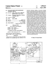
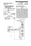
7
4,345,764
8
D2 and conductor 99 to the emitters of the series of
applied from the micro-controller to the LO terminal
PNP transistors 101, previously referred to, enabling
and sequentially through the DO terminal D1, terminal
those transistors.
Another ?lter capacitor C3 is connected between
ground bus 97 and the cathode of diode D2. The con
ductor 99 is also coupled through conductor 102 to the
emitter of PNP transistor Q3. Conductor 102 is con
nected through resistor R2, conductor 104 to one side
of loud speaker 86. The other side of loud speaker 86 is
connected through conductor 103 to the collector of
D2, terminal D3, terminal GO or the terminal G1.
If, at this time, the defending spaceship is aligned
with column A, and not behind a viable barrier, then the
spaceship will be “hit” and “destroyed”. The micro
controller knows the position of the spaceship at the
time of dropping of the bomb and indicates the destruc
tion of the spaceship by a burn and a distinctive noise
transmitted through the loud speaker 86. The player
still has two remaining defending spaceships.
NPN transistor ampli?er Q4.
If, while the spaceship and the invaders are aligned,
the player presses the ?re button 18, a low signal is
The base of transistor Q3 is connected through resis
tor R3 to the sound output S0 of the micro-controller
91. The collector of transistor Q3 is connected through
a voltage divider comprising resistors R4 and R6 in
transmitted from the G3 terminal of micro-controlled
91 through diode D6, ?ring switch 18, conductor 116 to
the G1, resistor R12 to'the'base of transistor Q2. This
series. The base of transistor Q4 is connected through
conductor 106 to the ground bus 97. Thus, sound signals
presents a low signal at the G2 terminal of the micro
from the controller activate the audio ampli?er to cause
the loud speaker to produce the required sounds.
When the game commences, the processor is pro 20
grammed to provide negative low signals to points D0,
D1, D2, D3, G0, G1 and G2. This causes transistors QA
through QE to conduct responsive to low signals at
points L0 through L5. At this time there is no low signal
at G2. Thus, transistor Q2 does not conduct. There is a
controller.
Responsive to that low signal, a low signal is applied
sequentially to the L0 through L7 terminals of the mi
ere-controller. The signals, in conjunction with the low
signal on the base of transistor Q2, cause LED’s 26A
through 26H to sequentially light up simulating the
movement of the death ray.
Since at this time the death ray LED’s of the wand
barrier LED’s 23 to energize. There also is a low signal
overlap the aligned invading spaceships, the ?rst in
vader overlapped LED is “destroyed” by the death ray.
at L2 causing the defending spaceship 24 to energize.
Responsive to the “destruction”, the micro-controller
At the beginning of the game, the barriers and col
umns of invading spaceships may or may not be aligned.
Similarly, the wand may be in a position where the
spaceship is or is not aligned with the barrier. The
player of the game operates levers 17A‘ and 17B to
sends a signal out through S0 to cause the loud speaker
to broadcast a distinctive noise indicating the “destruc
vertical conductor on the matrix, such as conductor
113, resistor R LA and back to the terminal LO of
When the barrier LED’s are between the invaders
and the defending spaceship, neither the invaders nor
micro-controller 91. The micro-controller is apprised of
the position of the defending spaceship relative to the
45 However, the randomly strewn bombs of the invaders
low signal at G1, and transistor Q1 conducts causing the
tion” of an invading spaceship. The “destruction” of the
invading spaceship is also recorded in the memory for
compilation of the ?nal score.
If a dropped bomb and death ray strike each other,
move the wand so as to cause the spaceship 24 to be
35 then the dropped bomb is not “destroyed”. The “de
positioned as desired.
struction” of an invading spaceship stops the death ray;
The position of the spaceship relative to the barriers
so that the death ray can “destroy” only one invading
is indicated to the micro-processor. For example, when
spaceship per ?ring. If the death ray is activated when
the brush 49 abuts the contact segments 46A through
the defending spaceship and invaders are not aligned,
46F on the board, a circuit is completed from G2 of
then the micro-controller causes a distinctive noise to be
micro-controller 49 through conductor 111, diode D3,
broadcast indicating a “miss”.
'
contact strip 48, brush 49, conducting segment 46, a
barrier strips in this manner.
Similarly, the position of the defending spaceship
relative to the columns of invading spaceships is indi
cated to the board when brush 44 abuts one of the con
ducting segments 42. Contact of the brush, segment and
strip completes a circuit extending from terminal G3 to
terminal L0 through L5 of the micro-controller 91,
through conductor 114, diode D4, conductor 43, brush
44, segments 42A through 42F through conductors,
such as conductor 113, a resistor, such as R LA, and
terminals, such as L0. The described circuit indicates to
the micro-controller that a defending spaceship and a
column of invaders are aligned. At this time the space
the defending spaceship can “destroy” each other.
act to gradually “destroy” the barriers. Similarly, when
the death ray of the defending spaceship “hits” the
barrier, it also partially “destroys” the barrier. In a
preferred embodiment the barrier is “destroyed” after
being “hit” 15 times either by bombs or death ray shots.
As the barrier is “destroyed”, its light becomes less
intense. Once the barrier is “destroyed” it no longer
protects thedefending spaceship from the bombs of the
invaders.
The alignment of the invaders and the barriers is
indicated when the metallic strip 87 on the board 19 is in
contact with the conducting element 89 on the board
47. The conducting element 89 is coupled to terminal
G0 of micro-controller'91. The metallic strip 87 is con
ships; and the invaders are vulnerable to the death ray 60 nected from a low signal at terminal G1 of micro-con
troller 91 through conductor 117, diode D6 and con
of the defending spaceship.
-
ship is vulnerable to the bombing by the invading space
ductor 118 to metallic strip 87. The receipt of the low
signal at terminal G0 indicates to the controller that
there is alignment between the invaders and the barrier.
controller sends signals sequentially, for example, down
a column. At that time if, for example A column is 65 When there is no low signal on G1, then the barriers
have been “destroyed”.
dropping the bombs, then the light of LED AA will
The micro-controller 91 may also be programmed to
brighten followed sequentially by the lights of LEDs
replace “destroyed” invaders by moving the surviving
BA, CA, EA and DA. This occurs when a'low signal is
The bombs are dropped randomly. With the initiation
of the micro-controller a bomb occurs when the micro