1
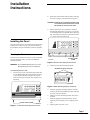
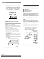
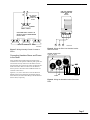
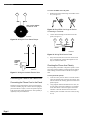
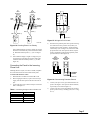
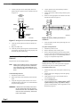
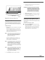
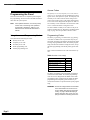
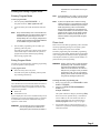
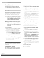
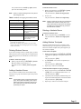
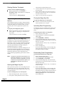
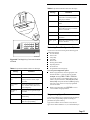
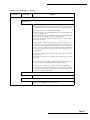
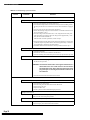
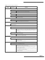
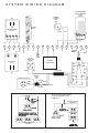
R
INSTALLATION INSTRUCTIONS
This document describes the procedures necessary for an experienced installer to install this panel. Refer to the
Commander 2000 Reference Manual (86-001-ITI) if you need more detailed information.
Installing the Panel ........................................................ [1]
Mounting the Panel ................................................. 1
Running Wire to the Panel ...................................... 2
Connecting Devices to the Panel............................. 2
Connecting the Panel to the Phone Line ................. 4
Installing and Replacing Backup
Batteries................................................................... 6
Installing the Battery Door...................................... 6
Plugging In the Panel .............................................. 7
Adjusting the Panel Speaker Volume...................... 7
Programming the Panel................................................. [8]
Using Access and Programming Codes .................. 8
Entering and Exiting Program Mode ...................... 9
Selecting Communication Locking......................... 9
Clearing Memory .................................................. 10
Programming System Devices .............................. 10
Programming Panel Configuration Options.......... 12
Programming from the Magic Key ....................... 12
Reviewing Panel Configuration Options............... 13
Programming Upper Sensors ................................ 13
Programming Feature Numbers ............................ 14
Requesting CS-4000 Programming ....................... 14
Installing Wireless Devices .......................................... [15]
Installing Wireless Sensors.................................... 15
Installing X-10 Lamp Modules.............................. 15
Testing the System........................................................ [15]
Testing Sensors...................................................... 15
Testing Phone Communication ............................. 16
Testing Central Station Communication .............. 17
Appendix A: System Planning Worksheets ............... [19]
Appendix B: Programming Tables............................. [21]
Appendix C: Command Summary ............................. [25]
User Command Summary ..................................... 25
Program Mode Command Summary ..................... 26
Appendix D: Troubleshooting..................................... [29]
®
Interactive Technologies, Inc.
2266 North Second Street
North Saint Paul, MN 55109
612/777-2690
Document Number 46-586 Rev. C
General notices:
This manual may refer to products that are announced but are not yet available.
If you experience trouble with this equipment, please contact:
Interactive Technologies, Inc.
2266 North 2nd Street
North St.Paul, MN 55109
for service and repair information. The telephone company may ask you to disconnect this equipment from the network until
the problem has been corrected or until you are sure that the equipment is not malfunctioning.
This equipment may not be used on coin service provided by the telephone company. Connection to party lines is subject to
state tariffs.
Trademarks:
ITI and Commander are registered trademarks of Interactive Technologies, Inc. X-10 is a registered trademark of X-10 (USA), Inc.
Installation
Instructions
Installing the Panel
2)
Remove the battery bucket from the panel by removing
the screw securing it on the right side (see Figure 2).
CAUTION: If batteries are in the battery bucket, make
sure that the exposed ends of the red and
black leads do not touch each other.
3)
Hold the panel upside-down against the wall at the
desired height and location (see Figure 3). If you plan
on attaching the Slim Line Hardwire Interior Siren (60483) to the right side of the panel, you will need at least
3 3/4 inches to the right of the panel.
Installing the Panel
POWER
1
2
3
4
5
POLICE
6
7
8
9
0
FIRE
READY
STAY
This section describes how to install the system and related
hardwire devices. Plan out your system before beginning
the installation, using the worksheets provided in Appendix
A.
AWAY
NO DELAY
COMMAND
STATUS BYPASS
AUX
TROUBLE
Mounting the Panel
The panel can be mounted on a sheet-rock wall, but depending on the mounting surface, you may need additional
mounting hardware.
BATTERY BUCKET
SCREW
8333G14A.DS4
Figure 2. Remove the battery bucket screw
WARNING: Do not disassemble the panel or you may
damage the panel or the mounting area.
4)
Mark the location of the mounting keyholes.
MOUNTING KEYHOLE LOCATIONS
To mount the panel on a wall:
Loosen the two screws on the bottom of the panel until
you can slide the battery door down and out (see Figure
1). Two full turns should be enough to allow you to
remove the battery door without removing the screws
completely.
TROUBLE
NO DELAY
STATUS BYPASS
COMMAND
AUX
AWAY
STAY
6
7
8
9
0
FIRE
READY
POWER
1
2
3
4
5
1)
POLICE
8333G16A.DS4
POWER
1
2
3
4
5
POLICE
6
7
8
9
0
FIRE
Figure 3. Mark Mounting Keyhole Locations
READY
STAY
AWAY
NO DELAY
STATUS BYPASS
COMMAND
AUX
TROUBLE
5)
6)
7)
BATTERY DOOR SCREWS
8333G78B.DS4
8)
Install the appropriate mounting hardware at the two
locations you just marked and hang the panel right side
up on the screws just installed.
Mark the two lower mounting keyholes, then remove
the panel.
Install the appropriate mounting hardware. Do not
tighten the lower mounting screws completely at this
time.
Hang the panel on the four screws.
Figure 1. Loosen the two battery door screws
Page 1
Installing the Panel
Gently tighten the lower screws to secure the panel to
the wall.
10) Insert the Quick Reference Card into the space at the
top, back side of the panel (see Figure 4). Make sure
that the “TEST WEEKLY” tab on the card is facing
out. Also, remember to fill this card out when the
install is complete.
9)
QUICK REFERENCE CARD
POWER
1
2
3
4
5
POLICE
6
7
8
9
0
FIRE
Refer to the wiring diagram on the back cover of this manual for basic wiring. Wire the following devices to the system, as necessary:
Hardwire sensors
Hardwire sirens and/or piezos
AC Power Transformer
For detailed information on installing peripheral and hardwire devices, see the Commander 2000 Reference Manual
and the installation sheets that accompany each device.
Refer to Table A.2 to calculate the hardwire device limit for
the system.
READY
STAY
Connecting Devices to the Panel
AWAY
NO DELAY STATUS BYPASS
TROUBLE
COMMAND
AUX
Connecting Hardwire Sensors to the
Panel
8333G29A.DS4
Figure 4. Quick Reference Card Location
Running Wire to the Panel
You must run wire from the panel to phone, power, and
hardwire devices. Do not run wires near fluorescent lighting
or parallel to AC power lines.
To run wires to the panel’s wire access area:
1)
2)
3)
4)
5)
Drill holes for the necessary wire runs in the wall, at
the back of the wire access area (see Figure 5).
Run the appropriate wire between each hardwire
device and the panel.
Feed wires through the holes just drilled in the panel’s
wire access area.
Mark each wire run so that you know which wires are
for each device.
Tie-wrap or secure the wires to a solid structure whenever possible.
The panel has one hardwire input for wiring hardwire sensors to the panel. You can use either a normally open or normally closed configuration. Both configurations require a
4.7k ohm end-of-line (EOL) resistor as the last device for
circuit supervision.
Normally open contacts are wired in parallel (see Figure 6),
while normally closed contacts are wired in series (see Figure 7).
USE EITHER SINGLE CONTACT OR MULTIPLE
CONTACT SERIES WIRING BUT NOT BOTH
(SHOWN IN CLOSED ALARM STATE)
MULTIPLE CONTACTS
IN PARALLEL
4.7k Ohm EOL
RESISTOR 49-365
MAGNET
SINGLE CONTACT
POWER
1
2
3
4
5
POLICE
6
7
8
9
0
FIRE
READY
STAY
AWAY
NO DELAY
STATUS BYPASS
COMMAND
AUX
TROUBLE
4.7k Ohm EOL
RESISTOR 49-365
8333G20A.DS4
Figure 6. Wiring Normally Open Contacts in
Parallel
WIRE ACCESS AREA
8333G17A.DS4
Figure 5. Panel Wire Access Area
Page 2
Installing the Panel
SLIM LINE HARDWIRE
INTERIOR SIREN AND
PIEZO
60-483-01
11
INPUT
GND
10
4.7k Ohm EOL
RESISTOR
ITI PART NO.
49-365
MAGNET
SINGLE CONTACT
USE EITHER SINGLE CONTACT OR
MULTIPLE CONTACT SERIES WIRING
BUT NOT BOTH.
12
MULTIPLE CONTACTS IN SERIES
13
14
8333G05D.DS4
8333G19B.DS4
Figure 7. Wiring Normally Closed Contacts in
Series
Connecting Hardwire Sirens and Piezos
to the Panel
Figure 8. Wiring the Slim Line Hardwire Interior
Siren and Piezo
HARDWIRE INTERIOR SIREN
ITI PART NO. 60-278
Sirens produce alarm sounds and piezos produce status
sounds in areas of the premises where the panel speaker cannot be heard. The only restriction to the number of sirens
and piezos that can be wired to the panel is the 290 mA maximum current draw. Refer to Table A.2 for the hardwire
devices you have selected for this installation and the current draw of each device.
Figures 8, 9, 10, and 11 show how to wire the Slim Line
Hardwire Interior Siren and Piezo, the Hardwire Interior
Siren and Piezo, the Piezo Status Beeper, and the Hardwire
Exterior Siren, respectively.
RED
BLACK
8333G07A.DS4
Figure 9. Wiring the Hardwire Interior Siren and
Piezo
Page 3
Installing the Panel
To connect the DB-8 cord to the panel:
12
RED
1)
13
Bend the ends of the terminal lugs on the DB-8 cord to
90° (see Figure 12).
BLACK
PIEZO STATUS BEEPER*
ITI PART NO. 30-006
Figure 12. Bend DB-8 Cord Lugs 90° Before
Connecting to Terminals
2)
8333G08A.DS4
Figure 10. Wiring the Piezo Status Beeper
Connect the terminal lugs on the DB-8 cord to the
panel (see Figure 13).
15
16
T
17
T1
BROWN
13
18
R1
R
GRAY
14
GREEN
RED
8333G24A.DS4
BLACK
RED
Figure 13. Wiring DB-8 Cord to Panel
3)
HARDWIRE
EXTERIOR
SIREN
13-046
Wrap each end of the four extra wires with electrical
tape to insulate them, and tape them together in case
they are needed for future use.
Checking the Phone Line Polarity
8333G09A.DS4
Figure 11. Wiring the Hardwire Exterior Siren
Reversed polarity somewhere in the phone system is a common cause of phone problems. Checking phone line polarity
before making connections reduces the risk of such problems.
To check phone line polarity:
Connecting the Panel to the Phone Line
1)
Connecting the Phone Cord to the Panel
The DB-8 cord provided with the panel is an 8-lead phone
cord with a modular plug. This cord lets the user unplug the
panel from the RJ-31X jack, to restore the premises phones
if the panel will not release the phone line. This capability is
required by many local ordinances.
Page 4
2)
3)
Locate the Telco protector block or network interface
where the telephone lines come into the premises. This
must be between the incoming phone line and the first
premises phone.
Using a digital voltmeter that measures DC volts, connect the positive lead of the voltmeter to one terminal
on the Telco block. Connect the negative lead of the
voltmeter to the other terminal on the Telco block.
Mark the positive terminal on the Telco block (see Figure 14).
Installing the Panel
(B)
TELCO
PROTECTOR
BLOCK
(A)
TELCO
PROTECTOR
BLOCK
GRY
GRN
RED
RED (+)
GRN
BLACK
PREMISES
PHONES
BLACK (-)
BLACK (-)
+
SPLICE
WIRE
-
DC VOLTS
RED
PREMISES
PHONES
WHITE OR
YELLOW
MARK
THIS +
MARK
THIS +
RED (+)
BRN
8333G72A.DS4
DC VOLTS
Figure 15. Wiring the RJ-31X Jack
8333G01C.DS4
4)
Figure 14. Checking Phone Line Polarity
If the voltmeter displays a positive voltage, the positive
terminal is connected to the positive lead of the voltmeter. Mark that terminal positive (+), (see A in Figure
14).
(A)
TELCO
PROTECTOR
BLOCK
or– If the voltmeter displays a negative voltage, the positive terminal is connected to the negative lead of the
voltmeter. Mark that terminal positive (+), (see B in
Figure 14).
Connecting the Panel to the Incoming
Phone Line
+
Installing the RJ-31X jack (CA-38A in Canada) completes
the connection between the Telco block and the panel.
2)
3)
Mount the RJ-31X within reach of the DB-8 cord.
Run a 22-gauge 4-lead wire, a splice-wire which you
supply, from the Telco protector block to the RJ-31X
jack.
Connect the splice-wire to the RJ-31X jack as shown in
Table 1 and Figure 15.
Table 1. Connecting the Splice-Wire to the RJ-31X
RJ-31X Terminals
Splice-wire
Green
Green
Red
Red
Gray
White or Yellow
Brown
Black
(B)
TELCO
PROTECTOR
BLOCK
-
PREMISES
PHONES
To connect the RJ-31X/CA-38A:
1)
Disconnect the premises phone line’s positive and negative leads at the Telco protector block, which you
located in the previous procedure, “Checking Phone
Line Polarity” (see A in Figure 16). If there are multiple phone lines at the Telco protector block, keep the
positive and negative leads grouped separately when
you disconnect (see B in Figure 16).
8333G73A.DS4
Figure 16. Disconnecting Premises Phones
5)
6)
Connect your splice-wire’s green and red leads to the
positive and negative Telco protector block terminals,
respectively (see A and B in Figure 17).
Connect your splice-wire’s black lead to the premises
phone’s positive wire(s), normally green (see C in Figure 17).
Page 5
Installing the Panel
7)
Connect your splice-wire’s white/yellow lead to the
premises phone’s negative wire(s), normally red (see D
in Figure 17).
TELCO
PROTECTOR
BLOCK
(A)
4)
5)
6)
Connect the black wire from the battery bucket to
panel terminal 6 (GND).
Connect the red wire from the battery bucket to panel
terminal 7.
Install six of the appropriate AA batteries in the order
and direction shown in Figure 18.
3
(B)
+
-
2
GRN RED
1
GREEN
+
+
+
RED
SPLICE
WIRE
BLACK
(C)
GRN
WHITE OR YELLOW
(D)
RED
1
2
PREMISES
PHONES
8333G74A.DS4
Figure 17. Wiring the RJ-31X Jack’s Splice-wire
3
Figure 18. Battery Polarity and Order of
Installation
7)
Check all premises phones for dial tone and dial-out
operation.
9) Plug in the DB-8 cord.
10) Check all premises phones again for dial tone and dialout operation. If the phones do not work properly, double-check the polarity and wiring.
8)
Secure the battery bucket in the panel using the screw
removed earlier.
To replace backup batteries:
1)
2)
3)
Installing and Replacing Backup
Batteries
Disarm the system to level 1.
Remove the battery door from the panel.
Remove the backup batteries from the battery bucket,
in reverse order of the installation shown in Figure 18.
Then proceed to step 6 in “To install backup batteries”
on page 6 to complete the replacement.
The panel uses six NiCd backup batteries.
Installing the Battery Door
Note:
Installing the battery door on the panel while in program
mode returns the panel to normal operation mode.
Make sure the batteries are fully charged before
installing them (see Appendix D: Troubleshooting on page 29). Fully charged batteries are at
least 1.2 VDC per battery or 7.2 VDC for six batteries.
To install backup batteries:
1)
2)
3)
Disarm the system to level 1.
Remove the battery door and battery bucket from the
panel.
Verify all wiring at the panel and devices for correct
terminations. Refer to the back cover of this manual for
the system wiring diagram.
WARNING: If batteries are in the battery bucket, don’t
let the exposed ends of the red and black
leads touch each other. The batteries could
drain, the wires could heat up, and the batteries could explode.
Page 6
8333G28A.DS4
To install the battery door:
1)
2)
3)
4)
Position the battery door on the panel as shown in Figure 19.
Slide the battery door straight up until it fits squarely
on the panel.
Gently tighten the two screws loosened earlier to
secure the battery door.
Press the STATUS button.
The panel should announce, Alarm system is OFF,
system battery is okay, AC power is okay. If
you hear a trouble message, refer to Appendix D: Troubleshooting on page 29.
Installing the Panel
3)
POWER
1
2
3
4
5
POLICE
6
7
8
9
0
FIRE
CAUTION: Use extreme caution when securing the
transformer to a metal outlet cover. You
could receive a serious shock if the metal
outlet cover drops down onto the prongs
of the plug while you are securing the
transformer and cover to the outlet box.
READY
STAY
AWAY
NO DELAY
STATUS BYPASS
COMMAND
AUX
TROUBLE
4)
PLACE BATTERY DOOR IN THIS POSITION,
THEN SLIDE UP
Unplug the transformer, then remove the existing screw
securing the AC outlet cover.
5)
Hold the outlet cover in place and plug the transformer
into the lower receptacle.
Use the screw supplied with the transformer to tighten
the transformer to the outlet cover.
8333G65B.DS4
Figure 19. Positioning the Battery Door
Plugging In the Panel
After you have made all the wiring and phone connections
to the panel and installed the backup batteries, plug in the
panel to power up the system and activate the backup batteries.
To plug in the panel:
1)
Plug the transformer into an outlet that is not controlled
by a switch.
The Power and Ready LEDs turn on, and the panel
announces, System nn, sensor mm, where nn is the
software version number and mm is the wireless sensor
capacity for the panel (from 01 to 17).
Note:
Adjusting the Panel Speaker Volume
The panel speaker has eight volume levels for status sounds
and status messages. Alarm sounds and messages are always
at full volume.
To adjust the panel speaker volume:
Press and hold COMMAND until the panel volume
reaches the desired level.
The panel repeats, Hello … once for each of the eight
available volume levels. It starts at level 8 (full volume) and ends with level 1 (low volume). When the
volume reaches level 1, it returns to level 8.
The first time the panel is powered up, the system sounds trouble beeps and all LEDs are on
steady, indicating that nothing has been programmed into memory yet.
If the Power and Ready LEDs are off and no voice
message is announced, unplug the transformer and
refer to Appendix D “Troubleshooting.”
Note:
If the TROUBLE LED blinks, it may be because
the NiCd batteries are low. The batteries may
need to be charged for 24 hours. Although the
panel can charge low batteries, the TROUBLE
LED may blink for up to 24 hours while the batteries are charging.
Note:
If you’re installing NiCd batteries, make sure the
batteries are fully charged before installing them
(see Appendix D “Troubleshooting“). Fully
charged batteries are at least 1.2 VDC per battery or 7.2 VDC for six batteries.
2)
Press STATUS to check the system’s condition.
Page 7
Programming the Panel
Access Codes
Programming the Panel
This section describes how to complete system configuration programming, which is the basic information that determines how the system operates.
Note:
User-updated information, such as the primary
access code, is set through user operations,
summarized in Appendix C, Table C.1 and
described in the Commander 2000 Owner’s
Manual.
Using Access and Programming Codes
This system has the following five codes:
Primary access code
Temporary access code
Secondary access code
Dealer programming code
Installer programming code
The primary access code, temporary access code, and secondary access code let the user arm and disarm the system,
bypass sensors, and operate the system. The temporary and
secondary access codes cannot be used to change access
codes or direct bypass sensors. The primary and temporary
access codes can be changed from the panel. See Table C.1
for a summary of user commands or the Commander 2000
Owner’s Manual for details on using these codes.
The four available secondary access codes can only be set
from the CS-4000. Refer to “Requesting CS-4000 Programming” on page 14 for the procedure to set these codes.
Programming Codes
The dealer programming code and installer programming
code allow two different service personnel entry into program mode. The dealer programming code allows the dealer
to change all programmable values. The installer programming code allows the installer to change all values, except
the dealer programming code and the primary phone number.
Table 2 shows the defaults for the codes used with the system.
Table 2. Default Code Settings
Name of Code
Default
Dealer Programming Code
4321
Installer Programming Code
4321
Primary Access Code
1234
Secondary Access Code
None
Temporary Access Code
None
The dealer programming code and installer programming
code share the same default. The installer programming
code can never be changed from the default. If the dealer
programming code is changed from the default, the dealer
programming code and primary phone number are protected, but the installer can perform all other panel programming.
WARNING: CommLock settings determine if the dealer
or the central station has control over an
account. Read “Selecting Communication
Locking” on page 9 before attempting to
program this panel. Also, check your company’s procedure for handling CommLock.
Page 8
Programming the Panel
is possible for a central station to lock your
account.
Entering and Exiting Program Mode
Entering Program Mode
Note:
If Central Station Lock is ON, you cannot change
the reporting format (P-Format) from the panel.
Note:
A panel can operate with or without a locking
method, however, it is not possible for a panel to
use both methods simultaneously. If the panel’s
dealer programming code is not the default,
Phone Lock is enabled and a CS-4000 cannot
enable Central Station Lock for that panel. If the
panel’s security code is not the default, Central
Station Lock is enabled and the panel will not
allow the dealer to change the dealer programming code.
To enter program mode:
1)
Enter the primary ACCESS CODE + 1.
The panel announces, Alarm system is OFF.
2)
Loosen the battery door until the READY LED turns
off.
Note:
3)
Every time the battery door is removed after the
initial STIME report, the panel’s tamper switch is
activated and the system begins a 2-minute
backup battery test. The charging voltage that is
normally present for NiCd rechargeable batteries
is not available during the battery test.
Enter the dealer programming code or installer programming code at the panel.
The LEDs on the panel begin to blink, and the speaker
sounds trouble beeps to indicate that the system is in
program mode. Perform all desired programming
before exiting program mode.
Exiting Program Mode
You must exit program mode after completing programming
to return the panel to normal operation.
Phone Lock
Phone Lock uses the dealer programming code to determine
who has programming privileges for the primary phone
number, used for panel reports to the CS-4000.
The dealer programming code and installer programming
code share the same default. When the dealer programming
code is changed from the default, the dealer programming
code and phone number are protected, but the installer can
perform all other panel programming.
WARNING: Clearing memory does not reset the dealer
programming code. If the dealer programming code is changed from the default,
make sure to document the new code in a
safe place. If you forget or lose your dealer
programming code, you can only reset the
primary phone number and dealer programming code by sending the panel to ITI.
To exit program mode:
Attach the battery door to the panel.
The LEDs on the panel stop blinking, and the speaker
stops sounding trouble beeps.
Selecting Communication Locking
The Communication Lock feature determines if the dealer or
the central station has control over the customer account.
Communication Locking accomplishes this with two independent locking methods:
Phone Lock
Central Station Lock
To change the dealer programming code:
1)
2)
The system confirms the change by announcing Okay.
If your company does not own the CS-4000 that will provide
monitoring, but you want to maintain control over customer
accounts, Phone Lock must be enabled before the panel
reports to a central station.
WARNING: The CS-4000 can place a Central Station
Lock on any panel account that has not
already been phone locked by the dealer. It
While in program mode, press AUXILIARY+ AUXILIARY + BYPASS.
Enter the new DEALER PROGRAMMING
CODE twice.
Example: 54325432
If the code was not repeated exactly, Central Station
Lock is enabled, or the code entered is the same as
another programmed code, the system announces,
Invalid, try again. Return to step 1 to try again.
3)
Exit program mode by replacing the battery door, or
continue on to perform any desired programming procedures listed below.
Page 9
Programming the Panel
Central Station Lock
To add a sensor to a group:
Refer to the CS-4000 Central Station Installation and
User’s Manual (46-056) for a complete discussion of the
Central Station Locking feature.
1)
While in program mode, press STATUS + [group
#]. Group number can be from 00 to 29 (see Table B.1
for group characteristics).
The panel announces, Sensor level [group #].
2)
Enter [Sensor #]. Sensor number can be from 01 to
17.
The panel announces, Sensor [sensor #]. Proceed
to step 3.
Clearing Memory
Before programming a new panel, clear the memory. If the
dealer programming code is different from the installer programming code, clearing memory does not clear the primary phone number or the dealer programming code.
Note:
Note:
When entering command sequences, both emergency buttons (POLICE, FIRE, and AUXILIARY) must be pressed at the same time to
register a single entry. If two entries are listed in
a step, both buttons must be pressed twice.
Do not attempt this procedure unless you are in
program mode, pressing both emergency buttons can result in an emergency alarm. You must
replace the battery door, or close the tamper
switch, before you can disarm the system to cancel the alarm.
If the panel announces, Invalid, try again, you have
selected a sensor number that has already been programmed or does not exist, or time has run out. Return
to step 1 to try again.
3)
Trip the tamper switch of the sensor you are programming within 4 minutes.
Table 3 describes how to trip the tamper switch for
each type of sensor.
The panel announces, [sensor #] okay, sensor
[next available sensor #].
4)
Repeat step 3 until the desired sensors are programmed
into the current group.
Return to step 1 to select a new group.
To add Keychain Touchpads as wireless sensors:
To clear panel memory:
1)
While in program mode, press POLICE + POLICE.
The panel beeps each time you press the buttons.
2)
Immediately press AUXILIARY + AUXILIARY.
The panel beeps each time you press the buttons.
1)
While in program mode, press STATUS + [group
#]. Group number must be unsupervised, either 01,
03, 06, or 07.
The panel announces, Sensor level [group #].
2)
Enter [sensor #]. Sensor number can be from 01 to
17.
The panel announces, Sensor [sensor #]. Proceed
to step 3.
The panel announces, Memory good-bye, system
nn, sensor mm, where nn is the software version
and mm is the number of wireless sensors the system
If the panel announces, Invalid, try again, you have
selected a sensor number that has already been programmed or does not exist, or time has run out. Return
to step 1 to try again.
can support.
Example: Memory good-bye, system four one,
sensor one seven
3)
To begin programming the panel, enter the DEALER
PROGRAMMING CODE or INSTALLER
PROGRAMMING CODE.
3)
Trip the Keychain Touchpad by simultaneously pressing the Arm and Disarm buttons, until the LED blinks.
The panel announces, [Sensor #] okay, sensor
[next available sensor #].
Programming System Devices
All system devices must be programmed to communicate
with the panel.
Adding Wireless Sensors
After completing the group assignment for each sensor in
Table A.3, use the following procedure to add all sensors.
Page 10
4)
Repeat step 3 until the desired sensors are programmed
into the current group. Return to step 1 to select a new
group.
To exit from adding sensors:
Press COMMAND.
Programming the Panel
The system announces, Invalid, try again, and the
panel exits from adding sensors.
Note:
To add the hardwire sensor:
1)
While in program mode, press STATUS + [group
#]. Group number can be from 00 to 29.
The panel announces, Sensor level [group #].
2)
Press 1 + 8.
The panel announces, Sensor one eight okay.
When you exit from adding sensors, the panel is
still in program mode.
Table 3. Methods for Tripping Learn Mode Sensors
Sensor ‡
Action
Door/Window †
Open sensor cover.
Portable Emergency Buttons
Press the appropriate emergency
button(s).
PIR Motion
Open PIR case.
Keychain Touchpad
Simultaneously press the Arm
and Disarm buttons until the
LED blinks.
Shock †
Open sensor cover.
System Smoke
Press test button and hold for 30
seconds until the test alarm
begins sounding.
Note:
Feature number F24 must be set to configure the
hardwire input as either normally open or normally closed. Refer to Table A.6 for the settings
and Table C.2 for the programming command
that sets feature numbers.
Deleting a Hardwire Sensor
To delete the hardwire sensor:
While in program mode, press BYPASS + 1 + 8.
The panel announces, Sensor one eight goodbye.
‡ Refer to the particular sensor’s installation instructions for
more details on tripping sensors.
† When using an external contact with this sensor, the contact
must be in the alarm state while tripping the sensor to properly
learn it into memory.
Deleting Wireless Sensors
If you want to reassign a sensor to another group, you must
delete that sensor first. The panel must be in program mode
when deleting sensors, but it should not be in learn sensors
mode.
Adding Wireless Touchpads
Wireless touchpads allow the user to control the system
without having to go to the panel. Most operations can be
done with a wireless touchpad. The system supports up to
four wireless touchpads.
To add wireless touchpads:
1)
1 to 4.
The panel announces, [ID #].
To delete a sensor from a group:
While in program mode, press BYPASS + [sensor
#]. Sensor number can be from 01 to 17.
The panel announces, Sensor [sensor #] good-
bye.
While in program mode, press STATUS + STATUS
+ [ID #], where [ID #] is a touchpad ID number from
2)
Press BYPASS on the wireless touchpad that you
want to add.
The panel announces, [ID #] okay.
3)
Repeat steps 1 and 2 for each touchpad.
To add Keychain Touchpads as wireless touchpads:
Adding a Hardwire Sensor
You can connect a hardwire sensor to the hardwire input,
and assign it to a group. The hardwire input is always sensor
number 18.
Note:
If the hardwire input is programmed into the fire
group, during alarm the auxiliary power output
switches off voltage momentarily when the system is disarmed. This resets smoke detectors
powered by the output.
1)
While in program mode, press STATUS + STATUS
+ [ID#]. ID # is a touchpad ID number from 1 to 4.
The panel announces, [ID#].
2)
Trip the Keychain Touchpad by simultaneously pressing the Arm and Disarm buttons, until the LED blinks.
The panel announces, [ID #] okay.
3)
Repeat steps 1 and 2 for each wireless touchpad.
Page 11
Programming the Panel
Deleting Wireless Touchpads
To delete a wireless touchpad from memory:
While in program mode, press BYPASS +
BYPASS + [ID #]. The ID number is a touchpad ID
number from 1 to 4.
The panel announces, [ID #] good-bye.
Programming Panel Configuration
Options
panel configuration options are numeric settings that affect
how the system operates and communicates. Use the panel
configuration settings you recorded on Table A.4 to program the system. You can program these options in any
order.
To program panel configuration options:
While in program mode, enter the command sequence
found in Table C.2, supplying your configuration setting variable.
The panel announces the variable and Okay.
Programming from the Magic Key
The Magic Key is a dime-sized programmable disk that can
be attached to a keychain. When used in uploader/downloader mode, you can copy panel configuration information
from a panel’s memory to the Magic Key. The Magic Key
copies all programmable panel settings, whether programmed from the panel or a CS-4000.
Once the panel information is uploaded, the Magic Key can
be used to download the information to any panel that you
want to have the same configuration. This is very useful for
maintaining a backup of a panel’s configuration or for
quickly transferring programming options between similar
systems.
Note:
The Magic Key uploads and downloads the complete panel configuration. If you only want to borrow a portion of a panel’s configuration, you must
modify the source panel before the upload or you
must modify the destination panel after the
download.
2)
3)
4)
Closing the Magic Key Slot
To replace the Magic Key cover in the panel:
To remove the Magic Key cover from the panel:
Before mounting the panel, look at the backside.
or– If the panel is already mounted, remove it from the
1)
Page 12
Insert the cover into the slot (see Figure 20). The
retainer tab holds the cover in place.
Uploading Panel Programming
The Magic Key must be programmed with a panel’s memory configuration before it can be used to program other
panels.
To upload the panel’s memory to a Magic Key:
1)
2)
3)
4)
5)
Remove the panel’s battery door.
Enter the DEALER or INSTALLER PROGRAMMING CODE.
Press COMMAND + STATUS.
Insert and hold the Magic Key in the key slot while
applying pressure until the panel begins to speak (may
take up to 5 seconds).
The panel announces, Memory okay, or see Table 4 for
alternate messages.
Remove the Magic Key.
If you hear a failure message, remove the Magic Key
and try again starting from step 3. If you continue to
hear failure messages, see Table 4.
Downloading Panel Programming
To download information from a Magic Key:
1)
2)
3)
4)
Opening the Magic Key Slot
Most systems have a plastic cover over the Magic Key slot.
You must remove this cover before the Magic Key can be
used. The following procedure explains how to remove the
cover from the panel.
wall by lifting it off the mounting screws.
Locate the square hole in the upper left corner of the
back of the panel.
Insert a small screwdriver into this hole and press to
release the cover retainer tab. The cover will extend
out of the slot about 1/4 inch.
Lift the cover out of the slot (see Figure 20).
5)
Remove the panel’s battery door.
Enter the DEALER PROGRAMMING CODE.
Press COMMAND, then BYPASS.
Insert and hold the Magic Key in the key slot while
applying pressure until the panel begins to speak (may
take up to 20 seconds).
The panel announces, Memory okay, or see Table 4 for
alternate messages.
Remove the Magic Key.
If you hear a failure message, remove the Magic Key
and try again starting from step 3. If you continue to
hear failure messages, see Table 4. The panel clears it’s
own memory to the default settings and announces
Memory goodbye if there is a download failure
from the Magic Key.
Programming the Panel
Table 4. Uploader/Downloader Mode Voice Messages
Message
POWER
1
2
6
7
3
4
5
POLICE
8
9
0
FIRE
Definition
Failure 4
Panel security code indicates
CSLOCK is ON; dealer programming key is disabled.
Failure 5
Panel is not in dealer programming
mode.
Failure 6
Magic Key communication failure;
panel will keep trying to communicate for 30 seconds.
Failure 7
No uses left in Magic Key.
Failure 8
Information did not transfer; repeat
procedure.
Failure, goodbye
Magic Key’s programming prevents
its use at this time.
READY
STAY
AWAY
NO DELAY
STATUS BYPASS
COMMAND
AUX
TROUBLE
8333G45A.DS4
Figure 20. The Magic Key Cover and Location
on Panel
Table 4. Uploader/Downloader Mode Voice Messages
Message
Definition
Memory okay
Upload/download was successful.
Memory goodbye
Download was unsuccessful. Panel
memory has been cleared; repeat
procedure.
nnn memory
okay
Successful completion of process;
nnn = number of uses (254 or less)
left in Magic Key.
Invalid, try
again
Key type is not recognized. Repeat
procedure.
Failure 2
30-second time-out for uploading or
downloading.
Failure 3
Attempt to upload to a key type that
does not accept uploading.
Reviewing Panel Configuration Options
You can review the current setting for the following panel
configuration options:
Account number
Duress code
Entry delay
Exit delay
House code
Primary phone number
Reporting format
Siren time-out
Programmed sensors and groups
To review panel configuration options:
While in program mode, enter the appropriate command from Table C.2, leaving off the [n] variable.
Example: Pressing FIRE + FIRE + STATUS
reviews the current account number setting. If set to
AB123, the panel announces, ON, ON, one, two,
three, okay. The panel announces, ON to signify any
letter entry. Letter entries can only be programmed
from the CS-4000.
While in program mode, press STATUS to review
sensor numbers and group numbers.
Programming Upper Sensors
Upper sensor numbers let you customize panel operation for
the user. These programming options are already programmed in the panel’s memory.
Upper sensor numbers can be turned on or off, but if an
upper sensor number defaults to on, we recommend that you
Page 13
Programming the Panel
leave it on. Use the settings you recorded on Table A.5
when programming upper sensor numbers.
To turn on upper sensor numbers:
While in program mode, press STATUS + [upper
sensor #].
The panel announces, [Upper sensor #] okay.
To turn off upper sensor numbers:
While in program mode, press BYPASS + [upper
sensor #].
The panel announces, [Upper sensor #] goodbye.
Programming Feature Numbers
Feature numbers set how the panel communicates with the
central station, the hardwire input, and the user. Use the settings you recorded on Table A.6 to program feature numbers
into the system.
To toggle feature numbers on and off:
While in program mode, press AUXILIARY + AUXILIARY + STATUS + [feature #].
The panel announces, [Feature #] ON or [Feature
#] OFF.
Requesting CS-4000 Programming
Although most information can be programmed from the
panel, some information must be programmed from the central station. Use the information you recorded on Table A.7
to inform the central station of your installation’s programming requirements.
Note:
The CS-4000 requires version 5.0 software (80105) or greater to support Commander 2000
reporting in the ITI format and Commander 2000
programming from the CS-4000.
To request CS-4000 Central Station programming:
1)
2)
3)
4)
Page 14
Contact your central station and ask the operator to
program the panel with the values you have recorded
on Table A.7.
Give the operator the panel’s account number and the
phone number of the premises, and ask them to call
back immediately.
Hang up the phone.
When the phone rings, enter ACCESS CODE + 8
at the panel.
The LEDs scroll. The premises phone line remains tied
up while the central station is programming the system.
5)
When the central station releases the panel, the LEDs
stop scrolling. The operator may call you to discuss the
programming.
Installing Wireless Devices
Installing Wireless Devices
Testing the System
Installing Wireless Sensors
You should test the system after installing a new system,
after servicing the system, and after adding or removing
devices from the system.
After you have learned the sensors into groups and programmed the system, see the installation instructions packaged with each sensor for installation procedures. Verify the
sensor numbers so that you install each sensor in its correct
location.
Installing X-10 Lamp Modules
Testing Sensors
We recommend that you do a sensor test at the beginning of
every installation, before the sensors are permanently
mounted. You should also do a sensor test whenever a sensor-related problem occurs.
When installing the X-10 Lamp Module, do not use extension cords to connect several lamps to one module. X-10
Lamp Modules can only be used with incandescent lighting.
Do not plug the X-10 Lamp Module into an outlet controlled
by a switch.
Note:
Note:
Performing the Sensor Test
You must power the system with the Line Carrier
Power Transformer when using X-10 Lamp Modules.
To perform the sensor test:
1)
To install the X-10 Lamp Module:
1)
2)
3)
4)
Plug the lamp cord into the bottom of the module.
Plug the X-10 Lamp Module into a lower AC outlet.
Refer to Table A.4 for the house code you programmed
into the Panel, then find the letter that corresponds to
that house code from Table B.2. Each letter setting represents 16 house codes.
Example: House code 113 corresponds with B on the
X-10 Lamp Module’s house dial.
2)
3)
4)
Place all sensors in their secured state, normally open
or normally closed.
Replace the battery door on the panel if the door is off.
Cover PIR lenses.
Enter the primary ACCESS CODE + 9 at the panel or
a touchpad.
The system sounds one long beep, then announces,
Sensor test is ON. Panel LEDs begin to scroll. You
have 15 minutes to complete the sensor test.
Note:
Set the house dial on the module to the appropriate letter.
Note:
While the sensor test is a valuable installation
and service tool, it only tests sensor operation for
the current conditions. You should perform a sensor test after any change in environment or
equipment.
The setting on the unit number dial does not
affect the operation of the module.
If the panel’s first STIME has passed (from 12 to
24 hours after power up), then the panel performs an automatic battery test whenever a sensor test is performed. The battery test lasts as
long as the panel remains in sensor test.
5)
Trip each sensor as described in Table 5.
The panel sounds transmission beeps as each sensor is
tripped. Each beep represents one data round.
6)
Count the number of transmission beeps and refer to
Table 6 for minimum requirements.
After the beeps, the panel speaker announces, Sensor
[sensor #] okay, confirming the sensor number
tested. If the system does not respond, or if the sensor
does not meet the minimum transmission beep requirements, refer to “If a Sensor Fails the Sensor Test” on
page 16.
7)
Press the STATUS button when you think all the sensors have been tested.
The system announces untested sensor numbers.
Page 15
Testing the System
8)
9)
Test all untested sensors.
Enter the primary ACCESS CODE + 9 while the system is still in sensor test if you need more time to complete the sensor test.
The system stays in sensor test for an additional 15
minutes, preserving the list of untested sensors. After
15 minutes, the panel disarms to level 1.
10) Enter the primary ACCESS CODE + 1 to exit sensor
test.
The system disarms to level 1, and the panel
announces, Alarm system is OFF.
Table 5. Trip Sensors for Sensor Test
Sensor ∆
D/W †
ƒ
ment. Mounting sensors within 100 feet of the panel reduces
the impact of environmental conditions that may exist on
the premises. Sometimes a change in sensor location can
help overcome adverse premises conditions.
To improve sensor communication, you can:
To reposition the sensor:
1)
2)
Action
Open the secured door or window. After
counting the beeps, close the door or
window.
PIR Motion
Avoid the PIR’s view for 5 minutes.
Enter its view, or use the PIR’s walk test
feature.
Shock
Tap the glass twice, away from the sensor. Wait 30 seconds between tests.
Smoke
Press and hold the test button until the
system sounds transmission beeps.
Emergency buttons on Press the appropriate button(s) until the
system transmission beeps stop.
Touchpads, Keychain
Touchpads and panel ‡
∆ Refer to a particular sensor’s installation instructions for details
on tripping sensors.
† D/W includes standard, Recessed, and Slim Line Door/Window
Reposition the sensor.
Relocate the sensor.
If necessary, replace the sensor.
Rotate the sensor and test for improved sensor communication at 90° and 180° from the original position.
If poor communication persists, relocate the sensor as
described below.
To relocate the sensor:
Test the sensor a few inches from the original position.
Increase the distance from the original position and
retest until an acceptable location is found.
3) Mount the sensor in the new location.
or– If no location is acceptable, replace the sensor as
described in the next procedure: “To replace the sensor.”
1)
2)
To replace the sensor:
Test a working sensor at the same location.
2) If the transmission beeps remain below the minimum
level, avoid mounting a sensor at that location.
or– If the replacement sensor works, contact ITI for repair
or replacement of the problem sensor.
1)
Sensors.
‡ Activate all portable emergency buttons and wireless touchpads
from various locations on the premises.
Testing Phone Communication
sensor. Restoring the sensor too soon results in a mixture of
transmission and restoral beeps.
Perform a phone test to check the phone communication
between the panel and the central station. A phone test takes
a maximum of 15 minutes to complete; however, most of
the time the phone test is much shorter.
ƒ Listen for the appropriate number of beeps before restoring the
Table 6. Minimum Transmission Beeps
Type of Sensor
Intrusion Sensors
Number of
Beeps
WARNING: Before performing a phone test, read
“Selecting Communication Locking” on
page 9. It is possible for a central station to
lock your account.
7 - 8 beeps
Wireless Environmental/Panic Buttons
7 - 8 beeps
Hardwire Loops
1
Panel/Touchpad Emergency Buttons
1
To perform a phone test:
1)
If a Sensor Fails the Sensor Test
If the system does not beep when the sensor is tripped, use
an RF Sniffer (60-401) to verify that the sensor is transmitting. Constant beeps from the RF Sniffer indicate a runaway
sensor. Remove the sensor’s battery and replace the sensor.
Locate sensors within 100 feet of the panel whenever possible. The receiver’s open air range is typically 800 feet, but
this range may vary depending on the installation environ-
Page 16
Enter ACCESS CODE + 8.
The panel speaker and all interior sirens sound one
long beep, and the panel announces, Phone test is
ON. Panel LEDs begin to scroll.
The system returns to level 1 when the phone test is
complete. The panel announces, Phone test is
okay, alarm system is OFF.
If the panel announces, Phone test failure, alarm
system is OFF, check to be sure the panel is
Testing the System
plugged into the panel’s phone jack. Proceed to the
next procedure, “If the phone test fails.”
If the phone test fails:
1)
2)
3)
4)
Check to be sure the panel is plugged into the RJ-31X
jack.
Enter ACCESS CODE + 8 again.
If the phone test fails again, check the phone number
programmed into the panel.
If the phone test fails again, check the phone connection wiring. Refer to “Connecting the Panel to the
Incoming Phone Line” on page 5.
Testing Central Station Communication
After performing sensor and phone test, check that the system is reporting alarms successfully to the central station.
Also verify that the X-10 Lamp Modules are operating correctly.
WARNING: Before performing a central station communication test, read “Selecting Communication Locking” on page 9. It is possible for a
central station to lock your account.
To test communication with central station:
1)
2)
3)
4)
5)
Call the central station and tell the operator that you
will be testing the system.
Arm the system.
Trip at least one sensor of each type — fire, intrusion,
etc. — to verify that the appropriate alarms are working
correctly.
If X-10 Lamp Modules are installed, check to be sure
they operate correctly.
The lights should come on steady during fire and auxiliary/medical alarms and flash during an intrusion
alarm.
When you finish testing the system, call the central station to verify that the alarms were received.
Page 17
Testing the System
Page 18
Appendix A: System Planning Worksheets
Appendix A: System Planning
Worksheets
Fill in customer information about this installation below.
Table A.3 Sensor Groups and Locations
No.
Group
Type and Location
01
02
03
Customer
04
05
Address
06
07
City
State/Province/ZIP
County
Phone
08
09
10
11
12
13
Table A.1 Wireless Sensors
14
Part No.
Description
Qty.
15
60-686-43
Door/Window Sensor
16
60-706-43
Shock Sensor
17
60-639-43
Motion Sensor
18
60-668-43
System Smoke Sensor
60-705-43
Water-Resistant
Emergency Sensor
60-687-43
Hi-Tech HandHeld Wireless Touchpad
60-707-43
Keychain Touchpad (2-Button)
60-659-43
Keychain Touchpad (4-Button)
Table A.4 Panel Configuration Settings
Feature
Table A.2 Hardwire Devices
Part
No.
Description
Qty.
mA
Total
Hardwire Sensors
Magnetic Contact
13-068 3
/8'' press fit
13-070
Magnetic Contact
—surface mount
Hardwire input
Choices
Default Setting
House Code
001-254
Duress Code
00-99
Siren Time-out
02-99 minutes
Entry Delay
08-88 seconds
32
Exit Delay
08-88 seconds
32
Account Number
00000-99999
00000
Primary Phone
Number
Up to 18 digits,
including pauses
Reporting Format
00 (ITI)
01 (4/2, 2300 Hz)
03 (4/2, 1400 Hz)
N/A
001
05
00
† Make sure phone format is set to 00 (ITI) when communicating
N/A
with ToolBox.
Hardwire Sirens
60-483
Slim Line Hardwire
Interior Siren & Piezo
60 mA
60-278
Hardwire Interior Siren
and Piezo
75 mA
30-006 Piezo Status Beeper
13-046 Hardwire Exterior Siren
Total Power Consumption cannot exceed
5 mA
100 mA
290 mA
Page 19
Appendix A: System Planning Worksheets
Table A.5 Upper Sensor Numbers
No.†
Table A.6 Feature Numbers
Description
No.†
Default Setting
80
Touchpad Fire Emergency
ON
81
Touchpad Police Emergency
ON
82
Touchpad Auxiliary/Medical
Emergency
Description
F21
Monitoring of DC main power supply, OFF
when not using AC power as the
main power source.
ON
F22
DTMF (touch-tone) dialing
F23
When ON, only Opening and Closing OFF
reports are stored in Event Buffer.
When OFF, all reports are stored in
Event Buffer.
F24
Hardwire input (OFF = normally
closed, ON = normally open)
OFF
F25
When ON, Panel arms to level 3 No
Delay when you press the lock
symbol on a Keychain Touchpad.
When OFF, panel arms to level 2
STAY. When pressed again, Panel
arms to level 3 AWAY.
OFF
F26
COMMAND button disarm
OFF
Panel alarm mute
83
Manual Phone Test
ON
84
Opening Report
OFF
85
Closing Report
OFF
86
Duress Alarm
ON
87
Force Armed
OFF
87
Auto Force Armed, always ON
ON
89
RF Touchpad Supervisory or
Low Battery
OFF
90
AC Power Failure
OFF
91
Panel Shut Down ‡
ON
91
Low Panel Battery
ON
92
Panel Tamper
ON
F27
93
Automatic Phone Test *
OFF
94
Receiver Failure
ON
95
Panel Back In Service
ON
F30 * When ON, panel makes sensor low
battery reports immediately. When
OFF, panel waits until STIME to
make sensor low battery reports.
96
Phone Failure
ON
98
Auto Event Buffer Dump
OFF
ON
sor numbers from the panel.
* If upper sensor 93 is set to ON and the time and date are not set,
from the panel.
* This feature can only be set from the CS-4000.
Table A.7 Central Station Programming
Automatic Phone
Test Frequency †
1-255 days
Extended Delay
1-8 minutes
Default
Setting
35
4
Secondary Phone Number Up to 18 digits, including pauses
PMODE
Secondary Access Codes
0 = PMODE0
1 = PMODE1
2 = PMODE2
3 = PMODE3 (ITI only)
4 = PMODE4 (ITI only)
5 = PMODE5
0
Up to 4 codes
STIME ‡
hh = 00-23, mm = 00-59
SUPSYNC
hh = 02-24
User #2 __ __ __ __
User #3 __ __ __ __
User #4 __ __ __ __
User #5 __ __ __ __
12
† This feature only functions if upper sensor 93 is ON.
‡ Panel makes its first STIME report between 12 and 24 hours after initial power, then every 24
hours at that time.
Page 20
OFF
OFF
† See Table C.2 for the command sequence to set these feature numbers
the panel calls the central station once a day until the time and
date are successfully assigned. After the time and date are set,
the auto phone test schedule goes into effect.
Choices
ON
F31 * When ON, panel sounds protest beeps OFF
when someone uses an RF device to
disarm if an alarm sounded while
they were away. When OFF, panel
does not sound protest beeps.
† See Table C.2 for the command sequence to set these upper sen-
Feature
Default Setting
Appendix B: Programming Tables
Appendix B: Programming Tables
This appendix contains tables for selecting sensor group numbers and X-10 Lamp Module house
codes. Table notes for Table B.1 appear at the bottom of the table, on the next page.
Table B.1 Sensor Group Characteristics
No.
Page 21
Name
Application
Alarm
Delay
Restoral
Supervisory
CS
Report
√
√
1, 2, 3
√
1, 2, 3
√
1, 2, 3
√
1, 2, 3
Chime
Arming
Levels
00
Fixed
Panic
24-hr audible fixed emergency buttons.
Police
Instant
01
Portable
Panic
24-hr audible portable emergency
buttons.
Police
Instant
02
Fixed
Panic
24-hr silent fixed emergency buttons.
Silent
Instant
03
Portable
Panic
24-hr silent portable emergency buttons.
Silent
Instant
04
Fixed
Auxiliary
24-hr auxiliary sensor, such as Pendant Panic or holdup button.
Auxiliary/
Medical
Instant
√
√
1, 2, 3
05
Fixed
Auxiliary
24-hr auxiliary emergency button.
Siren shutoff confirms CS report.
Auxiliary/
Medical
Instant
√
√
1, 2, 3
06
Portable
Auxiliary
24-hr portable auxiliary alert button.
Auxiliary/
Medical
Instant
√
1, 2, 3
07
Portable
Auxiliary
24-hr portable auxiliary button.
Siren shutoff confirms CS report.
Auxiliary/
Medical
Instant
√
1, 2, 3
08
Special
Intrusion
Special belongings, such as gun cabinets and wall safes.
Police
Instant
√
√
√
1, 2, 3
09
Special
Intrusion
Special belongings, such as gun cabinets and wall safes.
Police
Standard
√
√
√
1, 2, 3
10
Entry/
Exit
Delay
Garage doors and entrances that
require a standard delay time.
Police
Standard
√
√
√
√
2, 3
11
Entry/
Exit
Delay
Garage doors and entrances that
require an extended delay time.
Police
Extended
√
√
√
√
2, 3
12
N/A. If this group is entered, group 11 is actually assigned.
13
Instant
Perimeter
Exterior doors and windows.
Police
Instant
√
√
√
√
2, 3
14
Instant
Interior
Interior doors. †
Police
Follower
√
√
√
2, 3
15
Instant
Interior
Interior PIR motion sensors.
Police
Follower
√
√
2, 3
16
Instant
Interior
Interior doors.
Police
Follower
√
√
3
17
Instant
Interior
PIR motion sensors.
Police
Follower
√
√
3
√
√
Appendix B: Programming Tables
Table B.1 Sensor Group Characteristics
No.
Name
Application
Alarm
Restoral
Supervisory
CS
Report
√
√
√
3
√
√
3
18
N/A. If this group is entered, group 17 is actually assigned.
19
Delayed
Interior
Interior doors that initiate a delay
before going into alarm.
Police
Standard
20
Delayed
Interior
PIR motion sensors that initiate a
delay before going into alarm.
Police
Standard
Local
Instant
Interior
24-hr local alarm zone protecting
anything that opens and closes.
Police
Instant
21
Local
Instant
Interior
Same as group 21, plus activation
initiates a delay before going into
alarm.
Police
22
Local
Instant
Auxiliary
24-hr local alarm zone protecting
anything that opens and closes.
Auxiliary/
Medical
Instant
23
Local
Instant
Auxiliary
24-hr local alarm zone protecting
anything that opens and closes.
Sirens shut off at restoral.
Auxiliary/
Medical
Instant
24
Local
Special
Chime
Notify the user when a door is
opened. Sounds emit from a local
annunciator.
Special
Chime
Instant
25
Fire
24-hr fire, rate-of-rise heat, and
smoke sensors.
Fire
27
Local
Custom
Door/Window sensor.
28
Local
Custom
Auxiliary
26
29
Arming
Levels
Delay
Chime
√
√
1, 2, 3
√
√
1, 2, 3
√
√
1, 2, 3
√
√
1, 2, 3
√
√
1, 2, 3
Instant
√
√
Silent
Instant
√
√
1, 2, 3
PIR motion sensor, sound sensor, or
pressure mat.
Silent
Instant
√
1, 2, 3
Freeze sensor.
Auxiliary/
Medical
Instant
Standard
√
√
√
√
1, 2, 3
1, 2, 3
Note: Check marks (√) represent characteristics which are present in a group.
† When open, the READY LED is off.
Page 22
Appendix B: Programming Tables
Table B.2 X-10 Lamp Module House Code Settings
X-10
Codes
Corresponding Panel House Codes
A
16
32
48
64
80
96
112
128
144
160
176
192
208
224
240
B
1
17
33
49
65
81
97
113
129
145
161
177
193
209
225
241
C
2
18
34
50
66
82
98
114
130
146
162
178
194
210
226
242
D
3
19
35
51
67
83
99
115
131
147
163
179
195
211
227
243
E
4
20
36
52
68
84
100
116
132
148
164
180
196
212
228
244
F
5
21
37
53
69
85
101
117
133
149
165
181
197
213
229
245
G
6
22
38
54
70
86
102
118
134
150
166
182
198
214
230
246
H
7
23
39
55
71
87
103
119
135
151
167
183
199
215
231
247
I
8
24
40
56
72
88
104
120
136
152
168
184
200
216
232
248
J
9
25
41
57
73
89
105
121
137
153
169
185
201
217
233
249
K
10
26
42
58
74
90
106
122
138
154
170
186
202
218
234
250
L
11
27
43
59
75
91
107
123
139
155
171
187
203
219
235
251
M
12
28
44
60
76
92
108
124
140
156
172
188
204
220
236
252
N
13
29
45
61
77
93
109
125
141
157
173
189
205
221
237
253
O
14
30
46
62
78
94
110
126
142
158
174
190
206
222
238
254
P
15
31
47
63
79
95
111
127
143
159
175
191
207
223
239
255 †
† This house code is reserved for demo Panels only.
Page 23
Appendix B: Programming Tables
Page 24
Appendix C: Command Summary
Appendix C: Command Summary
This appendix contains a summary of all system commands and what each command does.
User Command Summary
Table C.1 provides a description of all commands for operating the system. For commands that
require an access code, use either the primary access code or the temporary access code unless
otherwise indicated. While these are called user commands, you may need to use some or all of these
commands during the installation and programming process.
Table C.1 Summary of User Commands
Action
Command
Short Command ∆
Voice Message Confirmation
Disarm to level 1.
ACCESS CODE + 1
COMMAND + 1 ‡
Alarm system is OFF.
Arm to level 2.
ACCESS CODE + 2
COMMAND + 2 †
Alarm system is ON, level 2.
Arm to level 2, No
Delay.
ACCESS CODE + 2 + 4
COMMAND + 2 + 4 †
Alarm system is ON, level 2, no delay.
Arm to level 2, Indirect
Bypass.
ACCESS CODE + 2 + BYPASS
Arm to level 3.
ACCESS CODE + 3
COMMAND + 3 †
Alarm system is ON, level 3.
Arm to level 3, No
Delay.
ACCESS CODE + 3 + 4
COMMAND + 3 + 4 †
Alarm system is ON, level 3, No delay.
Arm to level 3, Indirect
Bypass.
ACCESS CODE + 3 + BYPASS
Alarm system is ON, level 3. Sensor [sensor #] bypassed.
Direct Bypass. ¥
primary ACCESS CODE + BYPASS
+ [sensor #]
Sensor [sensor #] bypassed.
Chime On/Off.
ACCESS CODE + 7
COMMAND + 7
ON, OFF.
Phone test On.
ACCESS CODE + 8
COMMAND + 8 ‡
Phone test is ON.
Sensor test On.
ACCESS CODE + 9
COMMAND + 9 ‡
Sensor test is ON.
Lights On/Off.
ACCESS CODE + 0
COMMAND + 0
ON, OFF
Define new primary
access code.
primary ACCESS CODE + STATUS
+ 8 + [new primary access code]
[new primary access code], okay.
Define new temporary
access code.
primary ACCESS CODE + STATUS
+ 7 + [new temporary access code]
[new temporary access code], okay.
Review alarm memory.
COMMAND + STATUS
Alarm memory is okay, or
Sensor [sensor #] [alarm type] alarm
memory.
Review panel status.
STATUS
Alarm system is... (see Owner’s Manual for
possible messages).
Alarm system is ON, level 2, sensor [sensor #] bypassed.
Adjust speaker volume. COMMAND (press and hold)
Hello…hello…hello…hello…
† This short command only works when arming to a higher level.
‡ This short command only works when feature number F26 is ON.
¥ This command only works if the sensor you are bypassing is active in the current security level.
∆ The COMMAND button will not work for arming and disarming if upper sensor numbers 84 and 85 are set to ON.
Page 25
Appendix C: Command Summary
Program Mode Command Summary
Table C.2 provides a description of all system commands you can use when the panel is in
program mode. To enter program mode, you can use either the installer programming code or the
dealer programming code, unless otherwise indicated.
Table C.2 Summary of Program Mode Commands
Action
Command
[n] Variable
Voice Message Default
Confirmation
‡
Add wireless touchpad.
STATUS + STATUS + [touchpad ID]
From 1 to 4
n Hello
Add wireless sensor.
STATUS + [group #] + [sensor #]
Group # from 00 to 29.
Sensor # from 01 to 17.
Sensor level [group
#], sensor [sensor #]
Clear panel memory.
POLICE + POLICE + AUXILIARY + AUXILIARY
Set feature number. †
AUXILIARY + AUXILIARY + STATUS +
[feature number]
Memory good-bye
[system # ] [version
#]
From 20 to 27
nn ON or nn OFF
Sensor nn good-bye
Delete a learned sensor.
BYPASS + [sensor #]
From 01 to 18
Delete primary phone number.
FIRE + FIRE + BYPASS + 1
Clears primary phone num- Phone...okay
ber
Delete wireless touchpad.
BYPASS + BYPASS + [touchpad ID]
From 1 to 4
n good-bye
Exit selected group during
sensor programming.
COMMAND
n/a
Invalid, try again
From 00 to 29
Sensor level nn
Select group number for sen- STATUS + [group #]
sor programming.
Set account number.
FIRE + FIRE + STATUS + [account number]
Any five digits
nnnnn okay
00-000
Set dealer programming
code. ¥
AUXILIARY + AUXILIARY + BYPASS + [new
dealer programming code] + [new dealer programming code]
Any four digits, repeated
okay
4321
Set duress code. ∆
POLICE + POLICE + [duress code]
From 00 to 99
nn okay
none
Set entry delay. ƒ
POLICE + POLICE + STATUS + [entry delay]
From 08 to 88
nn okay
32
Set exit delay. ƒ
POLICE + POLICE + BYPASS + [exit delay]
From 08 to 88
nn okay
32
Set house code.
FIRE + FIRE + [house code]
From 001 to 254
nnn okay
001
Set primary phone number.
¥£
FIRE + FIRE + BYPASS + [primary phone number]
From 2 to 18 digits. Press
FIRE + FIRE to insert
pauses.
Phone nnnnnnn
okay
none
Set reporting format. *
COMMAND + AUXILIARY + AUXILIARY +
[reporting format]
00 = ITI,
01 = 4/2 (2300 Hz),
03 = 4/2 (1400 Hz)
nn okay
00
Set siren time-out.
AUXILIARY + AUXILIARY + [siren time-out]
From 02 to 99
nn okay
05
Page 26
Appendix C: Command Summary
Table C.2 Summary of Program Mode Commands
Action
Command
[n] Variable
Voice Message Default
Confirmation
‡
Turn off upper sensor number. µ
BYPASS + [upper zone number]
From 80 to 98, except 88 and Sensor nn good-bye
97
Turn on upper sensor number. µ
STATUS + [upper zone number]
From 80 to 98, except 88 and Sensor nn okay
97
† Refer to Table A.6 for feature number descriptions.
‡ All programmed options with entries in the Default column, except dealer programming code, can be reviewed for the current setting. Review
programmed settings by entering the corresponding command, leaving off the [n] variable. For example, to review the current duress code setting, press POLICE + POLICE. The system announces nn okay, where nn is the current duress code setting.
¥ If the dealer programming code has been changed, Phone Lock is enabled and the primary phone number can only be changed using the new
dealer programming code. The installer programming code will not allow you to program the primary phone number.
∆ The first two digits of the duress code are the first two digits of the primary access code.
ƒ Entries greater than 08 round down to the nearest multiple of 8. Entries less than 08 round up to 8.
£ Primary phone number can be up to 18 digits including pauses, if set from the CS-4000. A secondary phone number is also programmable from
the CS-4000.
µ Refer to Table A.5 for upper sensor number descriptions.
* If CS-Lock is ON, P-Format can only be changed from a CS-4000.
†† Make sure reporting format is set to 00 (ITI) when communicating with ToolBox.
Page 27
Appendix C: Command Summary
Page 28
Appendix D: Troubleshooting
Appendix D: Troubleshooting
This appendix contains a summary of system troubleshooting techniques.
Table D.1 Troubleshooting System Problems
Device
Problem
Solution
Access Code
Customer cannot remember their access code.
1. Check your records to see if you have the customer’s access code on file.
2. If Panel is monitored, trap the Panel and reset the access code from the CS-4000.
3. If Panel is not monitored, clear memory and reprogram the Panel locally.
Arming/Disarming
System won’t arm.
1. If arming to level 2, be sure all monitored perimeter doors and windows are closed
(READY LED will be ON or flashing).
2. If arming to level 3, be sure all perimeter and interior sensors are closed (READY
LED will be ON).
3. Press the STATUS button for a voice message of the problem.
Batteries
Panel announces, System Battery Failure.
Replace the Panel backup batteries.
Panel announces, Sensor [sensor #] low battery.
Replace the sensor batteries.
Bypass
Panel announces, Invalid, Try again when you attempt to bypass a sensor.
You are trying to bypass a 24-hour sensor that cannot be bypassed or a sensor that is
not active in the current security level. You don’t need to bypass this sensor.
System cancels sensor bypass when you try to arm to level 2 or 3.
Arm to the desired level before you try bypassing a sensor.
Central Station Reporting
Central station is not receiving reports.
1. Check that the DB-8 Cord is plugged into the RJ-31X Jack.
2. Check for proper wiring of the RJ-31X Jack.
3. Verify the phone number of the receiver line with the central station operator.
Reprogram the phone number and retest, if necessary.
4. Replace the RJ-31X Jack.
5. Check that the DB-8 Cord is properly wired to the Panel terminals.
6. Replace the DB-8 Cord.
7. Check that the premises phone line is working.
8. Perform a phone test.
Page 29
Appendix D: Troubleshooting
Table D.1 Troubleshooting System Problems
Device
Problem
Solution
False Alarm
Alarm is being sent.
Enter ACCESS CODE + 1 to cancel the alarm. This command bypasses the alarm if
done within 8 to 20 seconds.
Hardwire Input
Panel does not respond to hardwire input activation.
Check that sensor 18 is programmed into Panel memory, and add if necessary.
Panel announces, Sensor one eight, trouble.
1. Check that the 4.7K ohm resistor is installed correctly in the circuit.
2. Check a normally open (N/O) circuit for a break in the wires.
3. Check a normally closed (N/C) circuit for a short in the wires.
4. Check feature number F24 for the correct setting.
Hardwire Siren
Exterior sirens are not producing alarm sounds.
Check for correct wiring at the siren and Panel terminals.
Exterior sirens produce status sounds.
Move the siren’s positive (+) wire from Panel terminal 12 to 14.
Interior sirens are not producing sounds.
Check for correct wiring at both the siren and Panel terminals.
Interior sirens produce low-volume alarm and high-volume status sounds.
Reverse the interior siren wires at Panel terminals 12 and 14.
Lights
Light using X-10 Lamp Module does not work.
See “X-10 Lamp Modules” in this table.
Panel
Panel does not power up.
1. Check the circuit breaker to be sure the circuit is live.
2. Check that the backup batteries are installed correctly, the battery bucket wires are
connected to the Panel, and the transformer is plugged in.
3. Check for proper wiring at the Panel and the transformer.
4. Measure the incoming voltage at the Panel terminals. A standard transformer reads
12 VAC at terminals 1 and 3.
Page 30
Appendix D: Troubleshooting
Table D.1 Troubleshooting System Problems
Device
Problem
Solution
Panel (Continued)
POWER LED is flashing, the TROUBLE LED is flashing, and pressing the STATUS button confirms, System Battery Failure.
1. Check the circuit breaker to be sure the circuit is live.
2. Check that the backup batteries are installed correctly, the tabs are making contact,
the battery bucket wires are connected to the Panel, and the transformer is plugged
in.
3. Check for proper wiring at the Panel and the transformer.
4. Measure the incoming voltage at the Panel terminals. A standard transformer reads
12 VAC at terminals 1 and 3.
5. Remove the backup battery power by either disconnecting the battery bucket’s red
wire from terminal 7 or by taking the batteries out of the bucket.
6. With a voltmeter, check the voltage at Panel terminals 6 and 7. The reading may
range from 9 to 14 VDC.
When the Panel is running a backup battery test, the reading at terminals 6 and 7
may range from 3.6 to 5.2 VDC. The Panel automatically runs a backup battery test
under the following conditions if the first STIME has occurred: (1) during the sensor test, (2) after activating the Panel’s tamper (including removing or installing the
battery door), when upper sensor 92 is ON, (3) once every 24 hours, at the programmed STIME.
If the voltage at terminals 6 and 7 is not within the range described in step 6, call
Technical Services.
If the voltage at terminals 6 and 7 is within the range described in step 6, continue
on to step 7.
7. Restore the backup battery power by either reconnecting the battery bucket’s red
wire to terminal 7 or by reinstalling the batteries in the battery bucket.
While the AC power transformer is plugged in, the Panel charges the batteries.
Once the batteries reach 7.0 VDC (measured while in battery test), the TROUBLE
LED turns off and the POWER LED stops flashing. If the trouble condition persists
after 24 hours, replace the NiCd batteries.
All Panel LEDs are flashing.
The Panel is in program mode.
All Panel LEDs are scrolling.
A system alarm has occurred since the Panel was last armed or Panel is in sensor test
or phone test. Press STATUS for a description of the alarm.
Page 31
Appendix D: Troubleshooting
Table D.1 Troubleshooting System Problems
Device
Problem
Solution
Panel (Continued)
Panel powers up but does not remain on.
1. Check the circuit breaker to be sure the circuit is live.
2. Check that the backup batteries are installed correctly, the tabs are making contact,
the battery bucket wires are connected to the Panel, and the transformer is plugged
in.
3. Check for proper wiring at the Panel and the transformer.
4. Measure the incoming voltage at the Panel terminals. A standard transformer reads
12 VAC at terminals 1 and 3.
5. Check the voltage at Panel terminals 6 and 7. The voltage should rise slowly, indicating the batteries are charging. When the voltage reaches approximately 7 volts
VDC, the Panel should turn back on.
If the Panel fails to remain operational, continue to step 6.
6. Remove the batteries from the battery bucket and check each battery’s voltage using
a voltmeter. Replace any batteries that are lower than approximately 1 volt or that
vary significantly in voltage from the other batteries.
7. Reinstall the batteries. If the Panel fails to remain operational, return to step 5.
Incoming voltage reading is 0.
1. Unplug the transformer.
2. Disconnect the wires from the transformer and the Panel.
3. Check for continuity (short) between any two wires or any open circuit on any wire.
POWER LED is off, and pressing the STATUS button confirms, AC Power Failure.
1. Check if the transformer is plugged into an outlet. Secure the transformer to the outlet with the screw provided.
CAUTION: Use extreme caution when securing the transformer to a
metal outlet cover. You could receive a serious shock if
the metal outlet cover drops down onto the prongs of the
plug while you are securing the transformer and cover to
the outlet box.
2. Check the connection from the transformer to the Panel.
Phones
Loss of dial tone on premises phones after wiring the RJ-31X Jack or connecting the DB-8 Cord.
1. Check the RJ-31X Jack’s wiring.
2. Check the wiring from the Panel terminals to the DB-8 Cord.
3. Replace the RJ-31X Jack.
4. Replace the DB-8 Cord.
5. Perform a phone test after troubleshooting the phone line.
Telephone does not work.
Disconnect the Panel from the phone jack. If the phone still doesn’t work, the security
system is not the cause of the phone problem.
Constant dial tone, preventing dial-out on premises phones.
Polarity-sensitive phones exist on the premises. Reverse the wires you connected to
the brown and gray wire terminals on the RJ-31X Jack.
Page 32
Appendix D: Troubleshooting
Table D.1 Troubleshooting System Problems
Device
Problem
Solution
Sensor
Panel announces, Sensor [sensor #] Trouble.
Put the sensor’s cover on, if it is off. Activate the sensor.
Panel announces, Sensor [sensor #] Failure.
The sensor is not communicating with the Panel.
Panel announces, Sensor [sensor #] low battery.
Replace the sensor’s battery.
Smoke Sensor
Beeps once every minute.
Batteries are low. Replace the smoke sensor batteries.
Trouble Beeps (see also Panel)
Press the STATUS button for a voice message of the problem. This disables the trouble beeps until the Panel
calls in its daily report.
Wireless Sensors
The Panel does not respond to sensor activity. There are no alarm, chime, or sensor test sounds.
1. Check that the sensor battery is installed.
2. Check the sensor battery for low voltage. Replace alkaline or lithium batteries, if
necessary.
3. Check that the sensor number is programmed into Panel memory. Program the sensor, if necessary.
The Panel responds intermittently to sensor signals.
1. Rotate the position of the sensor from 90° to 180°.
2. Mount the sensor in a different location.
Wireless Touchpads
The Panel does not respond to touchpad commands.
1. Operate touchpads from different locations within the premises to identify areas of
intermittent operation.
2. Program the touchpads into the Panel.
X-10 Lamp Modules
Lights controlled by the X-10 Lamp Module do not work.
1. Check that the lamp has a working bulb.
2. Confirm the lamp’s operation at a working outlet.
3. Check that the lamps are plugged into X-10 Lamp Modules and the X-10 Lamp
Modules are plugged into outlets that are not controlled by a switch. Relocate to
nonswitched outlets, if necessary.
4. Check that the Panel is powered by the Line Carrier Power Transformer, and not the
2-wire standard Class II Power Transformer.
5. Check that the HOUSE dial on the X-10 Lamp Module matches the house code programmed into the Panel.
Page 33
Appendix D: Troubleshooting
Page 34
SYSTEM WIRING DIAGRAM
SLIM LINE HARDWIRE
INTERIOR SIREN AND
PIEZO
60-483-01
+
HARDWIRE
EXTERIOR
SIREN
13-046
+
+
BATTERY
BUCKET
+
LINE CARRIER XFMR
60-346-500*
+
BLACK
RED
TELCO
PROTECTOR
BLOCK
GND
13
14
15
T
16
T1
17
18
R1
R
GRAY
BROWN
GREEN
RED
SEE BOXED
FIGURES BELOW
RED
BRN
GRY
GRN
RED
EXISTING
PHONE
LINE
SPLICE
BLACK
GREEN
RED
WHITE OR YELLOW
SPLICE
10
USE EITHER SINGLE CONTACT OR
MULTIPLE CONTACT PARALLEL WIRING
BUT NOT BOTH (SHOWN IN CLOSED
ALARM STATE).
MULTIPLE CONTACTS
IN PARALLEL
MULTIPLE CONTACTS
IN SERIES
8333G04D.DSF
WHITE OR YELLOW
SPLICE WIRE
RED
PREMISES PHONE JACK
12
HIS
INPUT
GND
11
GRN
GREEN
10
BLACK
CLASS II XFMR
60-515
9
6.5-12 +VDC
ALKALINE
8
7
OPTIONAL
COMMUNICATIONS
OUTPUT
6
GND
5
NiCd
4
AC IND
CCS
GND
+DC
3
HES
+
2
1