1
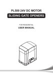
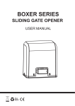
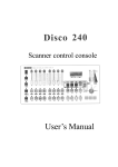
S32
2 AXIS POSITION
CONTROLLER
KARAÇÝM ELEKTRONÝK
BESEVLER KUCUK SANAYI SITESI ERTUGRUL CAD.
SATIS BLOKLARI NO:18/3 - BURSA
TEL : +90 (224) 441 12 97
FAX : +90 (224) 441 98 05
e-MAIL : [email protected]
S32 TWO AXIS POSITION CONTROLLER
s.1
FEATURES
two axis
Operation in manual, in single positioning, in programme modes
Memory capacity up to 99 programs, each one 33 steps
Counter [0-9999]
Easy calibration
Single point / double point calibration possibility
Error messages and warning messages
Retract function
Two speed positioning and autýmatic stop offset calculation software
External START / STOP inputs
Programs and parameters is stored in memory ten years
PRINCIPLES OF OPERATION
The S32 controller is used to position machinary to any desired absolute position with 2 speed reversing drives
on the basis of fast / slow / stop.
The controller outputs can be selected to operate :
1. Forward and reverse contactors.
2. Run and reverse, fast and slow for inverter systems.
3. Run and reverse, fast and slow for two speed motors.
Position is monitored by means of an incremental encoder (NPN). The actual position of the axis is displayed
at all times. The controller calculates the difference between the actual and demanded position and sets the outputs
to give the direction and speed to move the demanded position.
If the distance is greater than the value set in parameter "slow speed distance" the drive will first set off at
high speed, as it reaches the distance from the demanded position equal to this parameter, the drive will drop to
its low speed. It will now run at the slow speed until it reaches a distance from the demanded position equal
to stop offset of the machinery then the drive stops.
The offset value which is due to inertia of the machinery learned by controller automatically.
If positioning does not occur within the limits set in parameter "tolerance",
the controller will try to carry if out again and again till the maximum set in "number of trials".
After the last attempt, positioning has not been carried out correctly, "position Ok" contacts will not close
indicating something wrong, press stop and check the system.
Providing a speed low enough is used, the overrun will be consistent at all positions, then the stopping
accuracy of +/- 0.1 mm can be achieved.
Retract value for the backstop set in the parameters would be used for example on a sheet metal bender,
where backstop has to retract ( move to a higher count value ) whilst the bend is taking place.
MANUAL SETTING-UP
To setup the machine and getting correct direction of rotation and correct encoder signals, proceed as follows:
1. Select manual mode
2. Press one of the keys 1, 2, 6, 7 to check the correct direction and fast / slow speed.
If incorrect, change the cabling accordingly.
3. Press forward key ( 1 or 6 ), the actual display should count up ( in positive quadrant ).
If incorrect direction of count is present, interchange A / B cables of encoder.
FRONT
p.2
Number of Step
Number of Program
Program Entry
Axis select leds
Y Actual Position
Mode select leds
X Actual Position
Mode select
Count Display
Numerical keypad
START
STOP
Calibration
Position OK led
Clear
Configuration parameters
Program or Step
Delete
Retract function
DISPLAY and KEYS
Y AXIS DISPLAY : Actual value is displayed for manual and single modes.
In auto mode, it shows the value programmed before.
X AXIS DISPLAY : Actual value is displayed for manual and single modes.
In auto mode, it shows the value programmed before.
COUNTER DISPLAY : It shows number of operations done (counts the count input)
Press C to clear the count value.
PROGRAM NO DISPLAY : Selected program no ( 1..99 )
STEP NO DISPLAY : Selected step no ( 1..33 )
SELECTED MODE : Leds indicate what mode is selected.
(M)anual: Manual positioning, (S)ingle: Single positioning, (A)uto: Programmed mode
OK LED : Operation is allowed only if OK led lighted.
e.g. Ok led is lighted off during positioning and operation is not allowed.
START : Run / Enter
CALIBRATION
( Only in Manual mode )
STOP : Stop / Exit
CONFIGURATION
( Only in Manual mode )
Mode select
Slow Motion for selected
axis ( Only in Manual )
Prpgram entry
Fast Motion for selected
axis ( Only in Manual )
Display clear /
Counter clear
Numerical keypad
Program or Step delete
RETRACT function select
MENU
p.3
R
Y
X
c
Y
X
c
Y
X
MANUAL
MODE
(X)
MANUAL
MODE
(Y)
Selected axis
Slow Forward
p.4
c
c
SINGLE
MODE
(SINGLE)
AUTO MODE
( PROGRAM )
Single
Positioning
Program
Run
p.5
p.4
Selected axis
Slow Backward
AUTO MODE
Repeat the Prg.
( Continuous )
Visualize the
Program
p.5
p.4
Selected axis
Fast Forward
p.4
Selected axis
Fast Backward
p.4
5 sec
New Program
p.7
Program Edit p.7
Delete
Program Entry
p.7
Counter
Clear
p.4
p.6
10 sec
Ñ
25 sec
Ñ
Retract
Function
Double Points
Calibration
Calibration
p.8
10 sec
Ñ
p.5
p.8
start-up
Loading
ex-fact
parameters
Configuration
Parameters
p.9
p.9
WORKING MODES
Y
X
Y
X
p.4
MANUAL MODE (Y)
Y axis selected, related keys used to position Y-axis.
MANUAL MODE (X)
X axis selected, related keys used to position X-axis.
SINGLE MODE
Y axis, X axis and Count values entered, with start positioning takes place.
AUTO MODE
Programmed position values can be called and used to position the machinery.
AUTO MODE ( REPEAT )
Selected program no is repeated continuously.
MANUAL MODE ( Y-axis and X-axis )
M key is pressed to light the led of desired axis and M led.
Y
Press 1 or 2 for SLOW forward or reverse positioning
X
Press 6 or 7 for FAST forward or reverse positioning
SINGLE MODE
M key is pressed to light the S led for single positioning.
Press START
..
Y-axis display blinks ( ready for value entry ),
Press numerical keys for the desired Y position.
Press START to enter the written value.
..
X-axis display blinks ( ready for value entry ),
Press numerical keys for the desired X position
Press START
..
# Counter display blinks ( ready for value entry ),
Press numerical keys for the desired count.
Press START to enter the values,
Positioning is carried out, when the position is found correctly OK contacts close (its led is on).
In this position, operations are counted, when the count is reached OK contacts open.
COUNT CLEAR
Press C to clear the counter. ( Only in Manual and Single mode )
AUTO MODE
p.5
Press M to light the Auto led.
..
Prog No display blinks ( ready for entry )
Press numerical keys for the desired program no.
Press START to enter.
Positioning is carried out for step 01 position values. If the position is found correctly, OK contacts close.
Operations are counted, when the count is reached OK contacts open, then positioning is carried out
for step 02 and it continues as before.
When the recorded steps are finished ( max. 33 steps ) it returns to step 01 and wait for start.
AUTO MODE ( REPEAT )
Press M to blink the Auto led.
..
R
Prog No display blinks ( ready for entry )
Press numerical keys for the desired program no.
Press START to enter.
Positioning is carried out for each step as in the auto mode.
When the recorded steps are finished, it returns step 01 and repeats the program again.
This continuous operation ( repeating the program ) is exited by pressing STOP.
PROGRAM VISUALIZATION
Press M to light the auto led.
..
Prog No display blinks.
Press numerical keys for the desired program no.
Press P.
Step 01 position and count values are displayed.
With each press P, steps are visualized one after the other.
Press STOP to exit.
RETRACT FUNCTION
OFF
ON
Backstop has to retract ( set retract value in parameters )
whilst the bend is taking place to bring to safe position.
Press RETR key to light its led.
Press RETR key to cancel to retract function.
mm
NOT : Retract Function
When retract input is closed, after retract delay ( Pr.21 ),
backstop is retracted for retract distance ( Pr.22 ).
By count input closing, positioning to orginal position takes place.
Pr.21 : Retract delay
Pr.22 : Retract distance
Pr.22
SET
Pr.21
RETRACT SW.
( to close )
COUNT SW.
( to close )
t
PROGRAM ENTRY and EDIT
p.6
Press M to light Manual led
Press and keep pressing P for 5 sec. Read "total progs" on the display.
First empty program
O AL
P
S
0002
..
Number of recorded programs
To delete the selected program.
To Exit, press STOP
c
Press numerical keys
for the desired program no.
Press START
Press STOP to exit
Press DEL to delete the displayed step
and remaining steps.
Number of fullfilled steps in the selected program
..
Press numerical keys
for the desired step no.
Press START
..
Y display blinks ( ready for entry )
Press numerical keys for the new Y-value.
Press START
..
X display blinks ( ready for entry )
Press numerical keys for the new X-value.
Press START
next Step
..
Count display blinks ( read for entry ) Press numerical keys for the new count value.
( If count value is 0, counter is ignored. )
Press START
PROGRAM ENTRY
p.7
Press M to light manual led
Press P for 5 sec,
read "total progs" on the display.
Display shows the first empty program.
Press START
Display shows Step 01
Press START
..
Y display blinks ( ready for entry )
Press numerical keys for the new Y-value.
Press STOP
two times
for exit
c
Press START
..
X display blinks ( ready for entry )
Press numerical keys for the new X-value.
Press START
next step
..
Count display blinks ( read for entry ) Press numerical keys for the new count value.
( If count value is 0, counter is ignored. )
Press START
PROGRAM ERASE
Press M to light manual led
Press P for 5 sec, read "total progs" on the display.
Display shows the first empty program.
..
Press numerical keys for the program no to be erased.
Press DEL
Press START
Press STOP to Exit.
During the programming ;
1. If a new program is written over an old program, to erase the displayed step and the remaining steps,
press DEL and then press START.
2. Erasing ALL programs : Press and keep pressing DEL, and energy is applied, release DEL.
After 15 sec, all programs are erased.
SINGLE POINT CALIRATION ( CORRECT POSITION )
p.8
Press M to light Manual led and the desired axis led.
Y
on the display.
Press CAL (5) for 10 sec. Read
..
X
Press numerical keys for the password. ( Supervisor Password = 1974 )
Press START
..
Press numerical keys for new value of the selected axis.
Press START. New value is read on the display.
DOUBLE POINT CALIBRATION
Press M to light manual led and the desired axis led.
Y
X
Press CAL (5) for 25 sec.
on the display.
Read
..
Press numerical keys for the password. ( Supervisor Password = 1974 )
Press START. Read
on the display
Bring the position minumum, manually.
Press START
..
Press numerical keys for the measured value entry.
Press START
Press START, Read
on the display.
Bring the position maximum, manually.
Press START
..
Press numerical keys for the measured value entry.
Press START
PARAMETERS
p.9
Press M to light Manual led.
Press CONF (0) for 10 sec. Read "Config" on the display.
..
Press numerical keys for the password. ( Supervisor Password = 1974 )
Press START.
Parameter no
Press STOP to exit
..
c
Press numerical keys
for the desired parameter no.
next parameter
Press START.
..
Press numerical keys for new value of the selected parameter.
Press START.
PARAMETER TABLE
Pr.No
Y
X
Pr.No
Fact.default
Fact.default
SLOW SPEED DISTANCE (mm) 01 11 0.50 / 30.0
RETRACT DELAY (0.01 sn)
21
0.20
PITCH (mm/tour)
02 12 0.16 / 10.00
RETRACT DISTANCE (mm)
22
5.0
ENCODER ( pulse / tour )
03 13 100 / 100
(Reserved)
23
0
DECIMAL POINT = 0..5
04 14 2 / 1
PASSW (4 digit) S.Pass = 1974
24
1971
TOLERANCE (mm)
05 15 0.02 / 0.2
(Reserved)
06 16 1 / 1
TOL.WINDOW BLANKING
( No=0, Yes=1 )
07 17 1 / 1
MINUMUM SET (mm)
08 18 1.00 / 10.0
MAXIMUM SET (mm)
09 19 100.00 / 750.0
NUMBER of TRIALS
10 20 10 / 10
EX-FACTORY PARAMETERS LOAD
keep pressing "1" and switch on the supply, read
on the display.
TECHNICAL SPECIFICATIONS
p.10
FUNCTION
Supply voltage
24VAC (+/-10%)
Position sensor
Encoder ( A,B ch. ), 12VDC / PNP, 10 kHz
Inputs
6 Digital inputs, 12 VDC/PNP
Outputs
7 Relay outputs, 3A, NO
Ambient temperature
0..50°C
Front Dimensions
W x H = 192 mm x 96 mm
Depth ( excl. terminals )
D = 86 mm
Panel cut-out
W x H = 186 mm x 92 mm
DATA
KLEMENS BAÐLANTILARI
Model : S32 - 2 Axis Position Controller
No
36-BACK
37-COM
38-S/F
39-S/F
27-COM
28-S/F
29-S/F
35-FORW
25-FORW
30-PE
31-(+)
X
axis
DESCRIPTION
12-OK
10-RESET
11-OK
8-COUNT
9-RERACT
6-START
7-STOP
4-COM (+)
( PNP INPUTS )
5-ENABLE
3-N
1-PE
2-L
24 VAC
110 VAC
220 VAC
Y
axis
20-PE
+90 (224) 441 12 97
www.karacimelektronik.com
21-(+)
KARAÇÝM ELEKTRONÝK
26-BACK
34-(-)
24-(-)
Q.C.
32-A
/
33-B
/
22-A
Date
23-B
Serial #
No
DESCRIPTION
1
PE
Protective Earth
20
PE
Protective Earth
2
L
Supply Line
21
(+)
Encoder Supply 12VDC
3
N
Supply Neutral
22
A
Encoder X - Ch. A
23
B
Encoder X - Ch. B
4
COM (+)
Common
24
(-)
Encoder Supply GND
5
ENABLE [1]
Enable ( NO )
25
FORW
X Forward
6
START
External Start ( NO )
26
BACK
X Backward
COM
Common
S/F
Open = Slow
Close = Fast
30
PE
Protective Earth
31
(+)
Encoder Supply 12VDC
32
A
Encoder Y - Ch. A
33
B
Encoder Y - Ch. B
34
(-)
Encoder Supply GND
35
FORW
Y Forward
36
BACK
Y Backward
37
COM
Common
S/F
Open = Slow
Close = Fast
7
STOP [2]
External Stop ( NC )
27
8
COUNT
Count Input ( NO )
28
9
RETRACT
Retract Input ( NO )
29
10
RESET
Reserved
OK
Ready Output ( NO )
11
12
NOT
[1] ENABLE must be shorted to common to enable
the positioning.
[2] STOP must be shorted to common to enable
the positioning. ( NK )
38
39
ERROR MESSAGESS
ERROR MESSAGE
p.11
DESCRIPTION
TO DO
Hardware Error
( Y Axis )
Apply to manufacturer
Hardware Error
( X Axis )
Apply to manufacturer
Out of limits
(parameters 8, 9, 18, 19)
Check the given set values
No change on the
display during calibration
Check encoder connections and mechanism
Incorrect direction
of count during calibration
Check encoder connections and change ch.A / B
Position is not found
Check and again try
INSTALLING
Attention ! :
To ensure a perfect function of the S32 the following insatllation guide-lines must be
strictly observed and followed. Otherwise the guarantee expires and
Karaçim takes no liability and guarantee for malfunctions or damages
e.g. by incorrect installed wires or other external sources of error or interference,
which are exactly explained below.
To guarantee a perfect operation of the S32, the following (external) measures have to
be taken additionally :
PLACE OF
INSTALLATION
Don't install the controller near to sources of interference generating strong inductive
or capacitive interferences or strong electrostatic fields.
Install the external power supply directly beside the controller to avoid long low voltage wires.
POWER
SUPPLY
Use a galvanic separation over an additional transformer.
WIRE
INSTALLATION
Install all wires for low voltage and encoders always separately from power wires.
Avoid to install these wires close to any contactor or contactor wires.
SHIELDING
All external signal wires have to be installed shielded :
1. Rotary encoder wires
2. Wires for all other input signals
3. Wires for all output signals
4. Wires from the power supply to the S32
All shields have to be connected centrally low ohm to PE ( Earth potantial ),
connect only one-sided at the S32.
IMPORTANT !
1. Don't connect the S32 GND tp PE
2. Don't connect the shielding on both sides to PE
3. If the protective ground potential is heavily "contaminated" by interference voltages,
try to connect the shielding to the GND potential instead of PE.
FAULT
CLEARANCE
If there occurs interferences in spite of applying all above mentioned measures
proceed as follows:
1. Add RC elements over contactor coils of AC contactors ( for example 0,1 uF/100ohm)
2. Add recovery diodes over DC inductances
3. Add RC elements over each engine phase ( in connector box of the engine )
4. Install a power filter before the external power supply