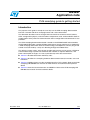
1
AN3287
Application note
PLM smartplug guide to getting started
Introduction
The purpose of this guide is to help the user fully use the PLM smartplug demonstration
board in a network with other smartplug boards and a data concentrator.
The document describes how to configure the board and how to interact with it; buttons,
LEDs, configuration jumpers, and all hardware components used, are described in detail. A
full description of the power line communication and its configuration and commands is also
provided.
The PLM smartplug demonstration board is based on the STM32F103VE microcontroller,
the ST7540 PLM module, and the STPM01 mono-phase energy metering IC. It implements
a PLM smartplug node which allows to monitor energy consumption of a mains plug and to
control it in on/off mode by a relay or in dimming through the T2035H Triac.
The voltage, current, power, active energy and the output status can be sent to a PLM data
concentrator through a power line communication network on request. Moreover, if the
power consumption changes, it is sent asynchronously to the data concentrator.
■
Section 1 describes document and library rules
■
Section 2 describes the smartplug hardware demonstration board, its modes, uses and
limitations
■
Section 3 highlights how to use the smartplug board in a PLC network. Refer to the PLM
smartplug FW UM1006 user manual for more firmware and communication protocol
details
■
Section 4 shows the board schematics and BOM list. Refer to the PLM smartplug HW
UM1005 user manual for more hardware details.
December 2010
Doc ID 18008 Rev 1
1/32
www.st.com
Contents
AN3287
Contents
1
Document and library rules . . . . . . . . . . . . . . . . . . . . . . . . . . . . . . . . . . . 5
1.1
2
PLM smartplug demonstration board . . . . . . . . . . . . . . . . . . . . . . . . . . . 6
2.1
Board introduction . . . . . . . . . . . . . . . . . . . . . . . . . . . . . . . . . . . . . . . . . . . 6
2.2
Main hardware components . . . . . . . . . . . . . . . . . . . . . . . . . . . . . . . . . . . . 8
2.3
Power-on and board usage . . . . . . . . . . . . . . . . . . . . . . . . . . . . . . . . . . . . 8
2.4
3
Acronyms . . . . . . . . . . . . . . . . . . . . . . . . . . . . . . . . . . . . . . . . . . . . . . . . . . 5
2.3.1
PLM smartplug application configuration . . . . . . . . . . . . . . . . . . . . . . . . . 8
2.3.2
PLM smartplug application running . . . . . . . . . . . . . . . . . . . . . . . . . . . . . 9
Board and application limitations . . . . . . . . . . . . . . . . . . . . . . . . . . . . . . . 12
PLM network and frames . . . . . . . . . . . . . . . . . . . . . . . . . . . . . . . . . . . . 13
3.1
PLM network parameters . . . . . . . . . . . . . . . . . . . . . . . . . . . . . . . . . . . . . 13
4
Bill of material . . . . . . . . . . . . . . . . . . . . . . . . . . . . . . . . . . . . . . . . . . . . . 14
5
Schematics . . . . . . . . . . . . . . . . . . . . . . . . . . . . . . . . . . . . . . . . . . . . . . . 24
6
Revision history . . . . . . . . . . . . . . . . . . . . . . . . . . . . . . . . . . . . . . . . . . . 31
2/32
Doc ID 18008 Rev 1
AN3287
List of tables
List of tables
Table 1.
Table 2.
Table 3.
Table 4.
Table 5.
Table 6.
Table 7.
List of acronyms . . . . . . . . . . . . . . . . . . . . . . . . . . . . . . . . . . . . . . . . . . . . . . . . . . . . . . . . . . 5
Jumper default position. . . . . . . . . . . . . . . . . . . . . . . . . . . . . . . . . . . . . . . . . . . . . . . . . . . . . 8
Terminal commands . . . . . . . . . . . . . . . . . . . . . . . . . . . . . . . . . . . . . . . . . . . . . . . . . . . . . . 10
Class variables description . . . . . . . . . . . . . . . . . . . . . . . . . . . . . . . . . . . . . . . . . . . . . . . . . 11
ST7540 configuration . . . . . . . . . . . . . . . . . . . . . . . . . . . . . . . . . . . . . . . . . . . . . . . . . . . . . 13
BOM . . . . . . . . . . . . . . . . . . . . . . . . . . . . . . . . . . . . . . . . . . . . . . . . . . . . . . . . . . . . . . . . . . 14
Document revision history . . . . . . . . . . . . . . . . . . . . . . . . . . . . . . . . . . . . . . . . . . . . . . . . . 31
Doc ID 18008 Rev 1
3/32
List of figures
AN3287
List of figures
Figure 1.
Figure 2.
Figure 3.
Figure 4.
Figure 5.
Figure 6.
Figure 7.
Figure 8.
Figure 9.
Figure 10.
Figure 11.
Figure 12.
4/32
STEVAL-IHP002V1 smartplug demonstration board . . . . . . . . . . . . . . . . . . . . . . . . . . . . . . 6
STEVAL-IHP002V1 PLM smartplug demonstration board block diagram . . . . . . . . . . . . . . 7
Network example . . . . . . . . . . . . . . . . . . . . . . . . . . . . . . . . . . . . . . . . . . . . . . . . . . . . . . . . . 9
Network example 1 . . . . . . . . . . . . . . . . . . . . . . . . . . . . . . . . . . . . . . . . . . . . . . . . . . . . . . . 11
Network example 2 . . . . . . . . . . . . . . . . . . . . . . . . . . . . . . . . . . . . . . . . . . . . . . . . . . . . . . . 12
Top page. . . . . . . . . . . . . . . . . . . . . . . . . . . . . . . . . . . . . . . . . . . . . . . . . . . . . . . . . . . . . . . 24
RS232 communication section . . . . . . . . . . . . . . . . . . . . . . . . . . . . . . . . . . . . . . . . . . . . . . 25
Power supply section . . . . . . . . . . . . . . . . . . . . . . . . . . . . . . . . . . . . . . . . . . . . . . . . . . . . . 26
Power line communication section . . . . . . . . . . . . . . . . . . . . . . . . . . . . . . . . . . . . . . . . . . . 27
MCU section . . . . . . . . . . . . . . . . . . . . . . . . . . . . . . . . . . . . . . . . . . . . . . . . . . . . . . . . . . . . 28
Energy meter . . . . . . . . . . . . . . . . . . . . . . . . . . . . . . . . . . . . . . . . . . . . . . . . . . . . . . . . . . . 29
Output drivers . . . . . . . . . . . . . . . . . . . . . . . . . . . . . . . . . . . . . . . . . . . . . . . . . . . . . . . . . . . 30
Doc ID 18008 Rev 1
AN3287
1
Document and library rules
Document and library rules
This document uses the conventions described in the sections below.
1.1
Acronyms
Table 1 lists the acronyms used in this document.
Table 1.
List of acronyms
Acronym
Meaning
APP
Application
API
Application programming interface
HAL
Hardware abstraction layer
RTOS
Real time operating system
PLM
Power line modem
PLC
Power line communication
MCU
Microcontroller unit
SPI
Serial peripheral interface
OOP
Object oriented programming
Doc ID 18008 Rev 1
5/32
PLM smartplug demonstration board
AN3287
2
PLM smartplug demonstration board
2.1
Board introduction
The application described in this document refers to the STEVAL-IHP002V1 demonstration
board (see UM1005).
Figure 1.
STEVAL-IHP002V1 smartplug demonstration board
The board includes the following functions shown in the block diagram of Figure 2:
6/32
●
Energy measurement by STPM01 IC
●
Power line communication by ST7540 up to 4.8 kbps
●
Isolated RS232 connectivity
●
Main AC load driving by Relay or Triac (by T2035H)
●
Auxiliary on/off contact for generic load driving.
Doc ID 18008 Rev 1
AN3287
PLM smartplug demonstration board
Figure 2.
STEVAL-IHP002V1 PLM smartplug demonstration board block diagram
Warning:
The board must be used only by expert technicians. Due to
the high voltage (220 Vac) special care should be taken with
regard to human safety. There is no protection against
accidental human contact with high voltages. After
disconnection of the board from the mains, none of the live
parts should be touched immediately because of the
energized capacitors. It is mandatory to use a mains
insulation transformer to perform any debugging/tests on the
board in which debugging and test instruments like USBJTAG dongles, spectrum analyzers, or oscilloscopes are
used. Do not connect any oscilloscope probes to high
voltage sections in order to avoid damaging instruments and
demonstration tools.
ST assumes no responsibility for any consequences which
may result from the improper use of this tool.
Doc ID 18008 Rev 1
7/32
PLM smartplug demonstration board
2.2
AN3287
Main hardware components
The following is a list of the PLM smartplug demonstration board main hardware
components:
●
An STM32F103CB microcontroller running the application firmware
●
An STPM01 mono-phase energy metering IC
●
An ST7540 power line modem: used to provide PLC connectivity to the system
●
1 bi-color status LED: green/red LED for application status scope
●
3 configuration jumpers (SW3, SW6, SW7): used for software configuration scope
●
2 user buttons (S3 and S4): used for user application scope
●
1 microcontroller reset button (SW4): used to force an MCU reset
●
4 jumpers for STPM01 calibration setting.
Detailed information about the PLM smartplug demonstration board hardware can be found
in the UM1005 user manual.
2.3
Power-on and board usage
Before turning on the board for the first time, make sure that the following configuration
jumpers are fitted or unfitted according the following default table:
Table 2.
Jumper default position
Jumper
SW2, SW5
SW3, SW6, SW7,
SW8, SW10, SW11, SW12
SW9
2.3.1
Description
Default
Boot option
– Fitted (1-2): boot option bit 0
– Fitted (2-3): boot option bit 1
Fitted (1-2)
General purpose configuration bit
– Fitted (1-2): configuration bit 1
– Fitted (2-3): configuration bit 0
Fitted (2-3)
STPM01 calibration mode
– Fitted (1-2): normal mode
– Fitted (2-3): calibration mode
Fitted (1-2)
Energy meter data line option
– Fitted (1-2): data line connected to SPI2-MISO
– Fitted (2-3): data line connected to SPI2-MOSI
Fitted (1-2)
PLM smartplug application configuration
The general purpose configuration jumpers are used to configure the smartplug type:
●
Relay: SW6=0, SW7=0, SW3=0
●
Dimmer: SW6=1, SW7=0, SW3=0
Before powering up the board, these jumpers must be set according to the board type. The
STPM01 is configured to work using the internal shadow latch which is loaded with
parameters stored in the internal flash of the MCU; however the STPM01 can be calibrated
by putting the jumpers SW8, SW10, SW11, and SW12 in calibration mode and using the on-
8/32
Doc ID 18008 Rev 1
AN3287
PLM smartplug demonstration board
board calibration connector before powering up the board. For details please refer to the
UM1005 user manual.
The first time the board is powered up, information regarding the addresses used for the
communication protocol and the network functions, which are stored in the MCU embedded
flash, are blank; therefore, after the first boot this information must be initialized using a PC
software application running on a PC connected to the board by the RS232 port; for details
about this configuration procedure please refer to the AN3046 application note. For the PLM
smartplug board the procedure described in AN3046 must be used only for configuration
purposes.
2.3.2
PLM smartplug application running
After configuration, the board can be used in a network; the address configuration of each
board must be consistent with the chosen network topology: Figure 3 shows an example of
a network and the related network addresses and node function configuration.
Figure 3.
Network example
The data concentrator firmware is also provided in order to build a complete network
solution; it can be loaded into one of the available smartplug boards (STEVAL-IHP002V1) or
it is possible to order STEVAL-IHP003V1 separately, which has a better form factor for PC
connection, and program it with the data concentrator firmware.
The data concentrator accepts commands, provides the command responses, and also the
asynchronous messages from smartplugs and some debug information through the RS232
connection; a basic I/O text terminal has been implemented through this connection in order
to provide the commands and print responses by text using a terminal PC software such as
“HyperTerminal”; the local echo of the terminal software must be enabled in order to have a
visual text feedback. Each text command must be completed by the <enter> key and are
“case” sensitive. The following commands are implemented:
Doc ID 18008 Rev 1
9/32
PLM smartplug demonstration board
Table 3.
AN3287
Terminal commands
Commands
Description
“get”
Used to request information to a remote smartplug. After the command, the modem answers with the
string “COMMAND->GET” to confirm the command acquisition and waits for one of the command
classes which identify the data to request. The command classes are described in Table 4
“set”
Used to write information to a remote smartplug. After the command, the modem answers with the
string “COMMAND->SET” to confirm the command acquisition and waits for one of the command
classes which identify the data to write. The command classes are described in Table 4
“identify”
Used to identify a specific smartplug inside the network. After the command, the modem answers
with the string “COMMAND->IDENTIFY” to confirm the command acquisition and wait for the string
“single” followed by the <enter> key to complete the command. The command completion is
confirmed by the string “CLS-> single”; after the command, the modem waits for the node ID to
identify printing the string “<NODE_ID>”. The smartplug identified by the inserted node ID blinks its
LEDs
“list”
Used to list the smartplug in the network already connected to the data concentrator. After the
command, the modem answers with the string “COMMAND->LIST NODES” and with the list of the
smartplug ID and address
“route”
Used to print the routing table. After the command, the modem answers with the string “COMMAND>ROUTE” and with the routing table
For the commands “get” and “set” it is possible to specify the class variable to write/read;
Table 4 describes these variables. The text terminal interface is also used to show debug
information: each received frame is printed in hexadecimal format and the payload
information is printed too, as shown in the following examples for the frame transferring all
measurement information and for the one transferring the status information:
Frame Rx ->
00 00 03 00 00 02 01 BC 82 03 00 00 00 00 00 00 00 00 00 00 00 00 00
01 BC 82 03 00 00 00 00 00 00 00 00 00 00 00 00 00
RSP Voltage -> 230076
Current -> 0
Power -> 0
Energy -> 0
Frame Rx ->
00 00 03 00 01 02 02 01 FF FF
02 01 FF FF
RSP Type -> 1
Main Val -> 255 Aux Val -> 255
In addition to the debug information, the information extracted by the application layer is
printed, as shown in the following example:
SmartPlug-id:voltage;current;power;
where
10/32
●
id: SmartPlug ID (0..255)
●
voltage: mains voltage in mV
●
current: load current in mA
●
power: load power consumption in W.
Doc ID 18008 Rev 1
AN3287
PLM smartplug demonstration board
After setting a new status of the mains output the smartplug sends back a frame with the
new status and the data concentrator prints out the following text message:
Status-id:status;
where
●
id: SmartPlug ID (0..255)
●
status: SmartPlug output status (0..255)
These strings can be easily interpreted by a PC application for a better presentation.
Table 4.
Class variables description
Class
“cons”
“all”
“status”
Description
Information variable that stores the power consumption. It is a read-only variable.
Information variable that stores all measurements:
– Voltage [mVolt]
– Current [mA]
– Power [mW]
– Energy [Wh]
It is a read-only variable.
Information variable that stores the status of both main output (relay/dimmer) and
auxiliary output (relay).
On top of “text user interface” described above, a demo PC GUI has been developed
working with only three smartplugs and one data concentrator. When the application is
opened, it shows the window in Figure 4, which allows to open the COM port for
communication with the data concentrator board and to use the text debug command and
also show response messages.
Figure 4.
Network example 1
Doc ID 18008 Rev 1
11/32
PLM smartplug demonstration board
AN3287
The demo window is shown by clicking on the “Demo” button, the window, illustrated in
Figure 5, is shown.
Figure 5.
Network example 2
The window allows identifying, setting the label, getting information from each smartplug
and monitoring the measurement variables. Once all labels are chosen, click the “Apply”
button to assign them. The smartplug can be controlled manually by the “plug control,
setting and monitoring” section or automatically by the “events scheduler” section of the
window. Once the scheduler is set, click on the clock control to start/stop it. The status of the
three smartplugs is also shown visually, considering three typical loads: a television, a lamp,
and a heater.
The smartplug application layer sends measurement information periodically only if the
measured power consumption changes, in order to avoid unnecessary network overload, so
if you want to get “fresh” data click on the “Get” button of the smartplug from which you want
data.
2.4
Board and application limitations
The smartplug is for demonstration purposes only so there are some limitations:
12/32
●
At startup there is a delay before the smartplugs start to send data to the concentrator
●
The STPM01 calibration hasn't been done to obtain the accuracy necessary for fiscal
metrology
●
The Triac has been tested with a maximum load equal to 1 kW
Doc ID 18008 Rev 1
AN3287
3
PLM network and frames
PLM network and frames
Details regarding the network information and frames can be found in the PLM smartplug
FW UM1006 user manual and in the AN3046 application note.
3.1
PLM network parameters
During startup, each node configures the ST7540 with the following parameters:
Table 5.
ST7540 configuration
Configuration parameter
Parameter value
Carrier frequency
132.5 kHz
Baud rate
2400 bps
Deviation
0.5
Watchdog
Disabled
Transmission timeout
Disabled
Frequency detection time
300 mSec.
Detection method
Preamble detection with conditioning
Mains interfacing mode
Synchronous
Output clock
Off
Output voltage level freeze
Disabled
Header recognition
Enabled
Frame length count
Disabled
Header length
16 bits
Extended register
Enabled
Sensitivity mode
Sensitivity high
Input filter
Enabled
Frame header
0xE389
Frame length
1
Configuration bytes values
0x1 0x89 0xE3 0xF7 0x94 0x17
Doc ID 18008 Rev 1
13/32
Bill of material
Table 6.
BOM
Reference
Part /
value
Tolerance
%
Voltage
current
AN3287
4
Watt
Technology
information
Packagefoot-print
9-way r/a PCB D
plug, US footprint Through hole
8.1 mm
Doc ID 18008 Rev 1
PORT 0
C1
2.2 µF
+/-10 %
50 V
Ceramic
capacitor X7R
SMD 0805
C5, C6
22 pF
+/-10 %
50 V
Ceramic
capacitor X7R
SMD 0805
C7
470 nF
+/-10 %
50 V
Ceramic
capacitor X7R
SMD 0805
C11, C12
33 pF
+/-10 %
50 V
Ceramic
capacitor X7R
SMD 0805
C14, C27,
C103
10 nF
±10 %
50 V
Ceramic
capacitorX7R
SMD 0603
C114,
C115
10 nF
+/-10 %
50 V
Ceramic
capacitor X7R
SMD 0805
C15, C17,
C24
10 µF
±10 %
16 V
Ceramic
capacitorX7R
C16, C18,
C25
100 nF
±10 %
50 V
C22
10 µF
±10 %
C116
47 nF
C101
10 µF
Any
Manufacturer
code
RS/Distrelec/
other
code
More
info
RS code: 1602590
muRata
GRM188R71H10 RS code: 2043KA01D
0779
SMD 1206
Kemet
C1206C106K4PA RS code: 648C7800
0755
Ceramic
capacitorX7R
SMD 0603
muRata
GRM188R71H10 RS code: 6244KA93D
2480
10 V
Ceramic
capacitor X5R
SMD 0805
muRata
GRM21BR61A10 RS code: 1066KE19L
846
+/-10 %
300 V
X2 Capacitor
Through
Hole
Any
RS code: 4419600
10 %
10 V
Tantalium
capacitor
SMD
Any
RS code: 4647619
Bill of material
14/32
CN1
Manufacturer
BOM (continued)
Part /
value
Tolerance
%
Voltage
current
C23
68 nF
±20 %
C26
6.8 nF
C30
Manufacturer
RS/Distrelec/
other
Technology
information
Packagefoot-print
Manufacturer
300 V
X2 Capacitor
Through
Hole
Any
±5 %
50 V
Ceramic
capacitor COG
SMD 1206
muRata
GRM3195C1H68 RS code: 6242JA01D
2597
15 pF
±5 %
50 V
Ceramic
capacitor COG
SMD 0402
muRata
GRM1555C1H15 RS code: 6240JZ01D
2935
C31
22 pF
±5 %
50 V
Ceramic
capacitor COG
SMD 0402
muRata
GRM1555C1H22 RS code: 6240JZ01D
2187
C32
270 pF
±5 %
50 V
Ceramic
capacitor COG
SMD 0603
Kemet
C0603C271J5GA RS code: 147C7867
207
C21, C33
100 pF
±5 %
50 V
Ceramic
capacitor COG
SMD 0603
muRata
GRM1885C1H10 RS code: 6531JA01D
0327
C68,C69,
C70,C71,
C102,C105
,C106,
C107,C93,
C97,C98,
C99,C100,
C104,C109
,C110,
C111,C112
,C113
100 nF
+/-10 %
50 V
Ceramic
capacitor X7R
SMD 0805
C91, C92
47 nF
+/-10 %
50V
Ceramic
capacitor X7R
SMD 0805
C94, C95
10 µF
+/-20 %
50 V
Electrolytic
capacitor
SMD
C108
1 nF
+/-10 %
50 V
Ceramic
capacitor X7R
SMD 0805
Reference
Watt
Doc ID 18008 Rev 1
code
More
info
Distrelec
code: 821885
RS code: 5369859
15/32
Bill of material
Any
code
AN3287
Table 6.
BOM (continued)
Part /
value
Tolerance
%
Voltage
current
C117,
C118
470 µF
+/-20 %
C96, C119
47 µF
C120
33 nF
DL1
Manufacturer
RS/Distrelec/
other
Technology
information
Packagefoot-print
Manufacturer
25 V
Electrolytic
capacitor low
ESR
Through hole
Any
Distrelec
code: 801846
+/-20 %
25 V
Electrolytic
capacitor
SMD
Any
RS code: 565712
+/-10 %
275 V
X2 capacitor
Through hole
Any
RS code: 118148
Red
Chip LED
SMD 0805
Any
Distrele code:
250154
DL2
Blue
Chip LED
SMD 0805
Any
Distrele code:
250159
D1
Bi-color
LED red
/ green
LED Bi-Red,
Green
SMD
Any
RS code: 419053
D6, D12,
D13
LL4148
Switching diode_
SOD-80
Any
Distrelec
code: 601496
D8, D10
BAT54S
Small signal
Schottky diodes
SOT-23
STMicroelectronics
BAT54SFILM
D9
SM6T15
CA
Transil
SMB
STMicroelectronics
SM6T15CA
D11
STPS14
0U
Power Schottky
rectifier
SMB
STMicroelectronics
STPS140U
F1
1A
TR5 anti-surge
submin PCB T
fuse
Through hole
Any
F2
15 A
Reference
Doc ID 18008 Rev 1
code
RS code: 6110658
Min fuse 15 A
5x20 mm
Socket for F2
code
More
info
RS code: 5414599
Through hole
Wickmann
652
Distrelec
code: 273260
AN3287
Socket for
F2
250
V/15 A
Watt
Bill of material
16/32
Table 6.
Reference
BOM (continued)
Part /
value
Tolerance
%
Voltage
current
Watt
Technology
information
Cap for
socket
Cap for
socket
Cap for socket
IC1
ST3232
EBDR
RS-232 drivers
and receivers
IC2
LD1117
DT50TR
Packagefoot-print
Manufacturer
Manufacturer
code
RS/Distrelec/
other
code
Distrelec
code: 273262
Doc ID 18008 Rev 1
Wickmann
655
SO-16
STMicroelectronics
ST3232EBDR
Low drop fixed
and adjustable
positive voltage
regulators
DPAK
STMicroelectronics
LD1117DT50TR
IC3
LD1117
ADT33T
R
Low drop fixed
and adjustable
positive voltage
regulators
DPAK
STMicroelectronics
LD1117ADT33T
R
JP4,JP5
Close
Do not fit
Do not fit
Do not fit
Do not fit
J1
Peak
meter
connect
or
5-way single row
strip line
connector (male
connector) 2,54
mm pitch
Vertical
through hole
Any
RS code:4958470
Rfid
reader
4-way single row
strip line
connector (male
connector) 2,54
mm pitch
Vertical
through hole
Any
RS code:4958470
JTAG
20-way IDC low
profile boxed
header 2,54 mm
pitch
Vertical
through hole
Any
RS code:
461770
J8
J2
More
info
AN3287
Table 6.
Do not fit
Bill of material
17/32
Reference
BOM (continued)
Part /
value
Tolerance
%
Voltage
current
Watt
Manufacturer
RS/Distrelec/
other
Technology
information
Packagefoot-print
Manufacturer
Vertical
through hole
Any
RS code:4958470
code
code
Doc ID 18008 Rev 1
J3
CON2
2-way single row
strip line
connector (male
connector) 2.54
mm pitch
J4
CON3
3-way screw
terminal block
5.08 mm pitch
Through hole
Any
RS code:1895865
J6
CAL
CON
10-way IDC low
profile boxed
header 2.54 mm
pitch
Vertical
through hole
Any
RS code: 461742
J7,J9
CON2
2-way screw
terminal block
7.5 mm pitch
Through hole
Phoenix Contact
L1
2x10
mH
0.5 A
Line filter
Through hole
Any
L5
22 µH
±10 %
2.1 A
Smd inductor
SMD
EPCOS
B82464A4223K
RS code: 4960445
L6
220 µH
±10 %
240 mA
Smd inductor
SMD
EPCOS
B82462A4224K
RS code: 4958048
L7,L9
1 mH
±10 %
330 mA
Smd inductor
SMD
EPCOS
B82464A4105K
RS code: 4960530
L8
10 µH
±10 %
1A
Smd inductor
SMD
EPCOS
B82442H1103K
RS code: 4961268
Q1,Q2
BC857B
PNP transistor
SOT23
Any
1988105
More
info
Bill of material
18/32
Table 6.
RS code: 5487301
Distrelec
code: 351276
RS code: 4452051
AN3287
Reference
BOM (continued)
Part /
value
Tolerance
%
Voltage
current
Watt
Manufacturer
Technology
information
Packagefoot-print
Manufacturer
D2PAK
STMicroelectronics
T2035H-6G-TR
STMicroelectronics
2STR1215
Doc ID 18008 Rev 1
T2035H
Q4,Q5
2STR12
15
Low voltage fastswitching NPN
power transistor
SOT-23
R3
1 kΩ
+/-5 %
1/2 W
Resistor
Axial through
hole
R6
1.1 kΩ
+/-1 %
0.1 W
Resistor
SMD 0603
R7
47 kΩ
+/-1 %
0.1 W
Resistor
SMD 0603
R8
15 kΩ
+/-1 %
0.1 W
Resistor
SMD 0603
R9
4.7 kΩ
+/-1 %
0.1 W
Resistor
SMD 0603
R88,R108,
R109
4.7 kΩ
+/-5 %
1/8 W
Resistor
SMD 0805
R10
13 kΩ
+/-1 %
0.1 W
Resistor
SMD 0603
R12
1 kΩ
+/-1 %
0.1 W
Resistor
SMD 0603
R62,R68,
R104,R106
1 kΩ
+/-5 %
1/8 W
Resistor
SMD 0805
R13
2.7 kΩ
+/-1 %
0.1 W
Resistor
SMD 0603
R14
1.8 kΩ
+/-1 %
0.1 W
Resistor
SMD 0603
R17
470 Ω
+/-1 %
0.1 W
Resistor
SMD 0603
R19
2.4 kΩ
+/-1 %
0.1 W
Resistor
SMD 0603
R85,R86,
R87
2.4 kΩ
+/-5 %
1/8 W
Resistor
SMD 0805
R20
56 kΩ
+/-1 %
0.1 W
Resistor
SMD 0603
code
More
info
AN3287
Q3
High
temperature 20 A
Snubberless™
Triacs
code
RS/Distrelec/
other
Bill of material
19/32
Table 6.
BOM (continued)
Part /
value
Tolerance
%
R21,R96,
R97
261 kΩ
+/-1 %
R59,R60
0
R61,R89
Voltage
current
Packagefoot-print
1/4 W
Resistor
SMD 1206
+/-5 %
1/8 W
Resistor
SMD 0805
560 Ω
+/-5 %
1/8 W
Resistor
SMD 0805
R63,R64,
R65,R66,
R71,R72,
R73,R74,
R76,R77,
R80,R81,
R82,R83,
R84
10 kΩ
+/-5 %
1/8 W
Resistor
SMD 0805
R67
(Not
mounted
)
+/-5 %
1/8 W
Resistor
SMD 0805
R69,R70
82 Ω
+/-5 %
1/4 W
Resistor
SMD 1206
R75
1 MΩ
+/-5 %
1/8 W
Resistor
SMD 0805
R91,R92
6.8 Ω
+/-1 %
1/4 W
Resistor
SMD 1206
R94
2 MΩ
+/-1 %
1/8 W
Resistor
SMD 0805
R98
475 Ω
+/-1 %
1/4 W
Resistor
SMD 1206
R99
43 kΩ
+/-1 %
1/8 W
Resistor
SMD 0805
R100
100 Ω
+/-1 %
1/8 W
Resistor
SMD 0805
R101
1 kΩ
+/-1 %
1/4 W
Resistor
SMD 1210
R102
22 Ω
+/-1 %
1/4 W
Resistor
SMD 1210
R103,R105
1 kΩ (do
not fit)
+/-1 %
1/4 W
Resistor
SMD 1210
R90,R93
1 kΩ
+/-1 %
1/8 W
Resistor
SMD 0805
Watt
Manufacturer
Manufacturer
code
RS/Distrelec/
other
code
More
info
Doc ID 18008 Rev 1
AN3287
Technology
information
Reference
Bill of material
20/32
Table 6.
BOM (continued)
Part /
value
Tolerance
%
R95
0
+/-1 %
R107
10
5%
RV1
S14K51
0
10 %
RS/Distrelec/
other
More
info
Packagefoot-print
1/8 W
Resistor
SMD 0805
1W
Fuse resistor
Axial through
hole
Any
Disk-shaped
metal-oxide
varistors
Through hole
Epcos
BOOT_0
3-way single row
strip line
connector (male
connector) 2.54
mm pitch
Vertical
through hole
Any
RS code:4958470
Single
strip line
3 pole
SW3
CONF3
3-way single row
strip line
connector (male
connector) 2.54
mm pitch
Vertical
through hole
Any
RS code:4958470
Single
strip line
3 pole
SW4
Rst
Surface mount
tactile switch
SMD
Any
RS code
183701
BOOT_1
3-way single row
strip line
connector (male
connector) 2.54
mm pitch
Vertical
through hole
Any
RS code:4958470
Single
strip line
3 pole
CONF0
3-way single row
strip line
connector (male
connector) 2.54
mm pitch
Vertical
through hole
Any
RS code:4958470
Single
strip line
3 pole
SW2
Doc ID 18008 Rev 1
SW5
SW6
Voltage
current
Manufacturer
Technology
information
Reference
510 VAC
Watt
Manufacturer
code
code
AN3287
Table 6.
RS code: 2140879
B72214S0511K1
Distrelec
01
code: 730933
Bill of material
21/32
BOM (continued)
Tolerance
%
Voltage
current
RS/Distrelec/
other
More
info
Packagefoot-print
Manufacturer
CONF1
3-way single row
strip line
connector (male
connector) 2.54
mm pitch
Vertical
through hole
Any
RS code:4958470
Single
strip line
3 pole
SW8,SW9, Calibrati
SW10,SW
on
11,SW12 settings
3-way single row
strip line
connector (male
connector) 2.54
mm pitch
Vertical
through hole
Any
RS code:4958470
Single
strip line
3 pole
RS code
183701
SW7
Part /
value
Manufacturer
Technology
information
Reference
Watt
code
Doc ID 18008 Rev 1
S3,S4
SW
push
Surface mount
tactile switch
SMD
Any
TP8,TP9,
TP10,TP11
,TP12,
TP13,TP14
,TP15,
TP16,TP17
,TP18,
TP19,TP20
,TP21,
TP22,TP23
,TP25,
TP26,TP27
Test
point
Test point
Test point
Test point
Test point
T1
Current
transfor
mer
Current
transformer
Through
Hole
VAC
T60404-E 4622X503
U1
SPAC26
5-3W
AC-DC switch
mode power
supply
U3
ST7540
FSK power line
transceiver
Through hole ST Microelectronics
ST Microelectronics
Test point
SPAC265BC12P
0.30
ST7540TR
AN3287
HTSSOP28
code
Bill of material
22/32
Table 6.
Reference
BOM (continued)
Part /
value
Tolerance
%
Voltage
current
Watt
Technology
information
Packagefoot-print
Manufacturer
Manufacturer
code
RS/Distrelec/
other
code
Doc ID 18008 Rev 1
U9
TSM050
5S
DC-DC converter
SOIC-14
Traco Power
TSM0505S
RS code: 5105431
U10
IL712S1E
Bi-directional
Digi Isolator
MSOP8
NVE
IL712S-1E
RS code: 418436
U11
STM32F
103CBT
6
Medium-density
performance line
ARM-based 32bit MCU
LQFP48
ST Microelectronics
STM32F103CBT
6
U12
STPM01
Programmable
single-phase
energy metering
IC with tamper
detection
TSSOP20
ST Microelectronics
STPM01FTR
W1 W3
Load
2-way screw
terminal block
7.5 mm pitch
Through hole
Phoenix contact
1988105
X1
16 MHz
16 MHz crystal
SMD
Any
RS code: 5476531
Y1
8 MHz
16 MHz crystal
SMD
Any
RS code: 6719242
k1
16 A 12
Vdc coil
(Do not
fit)
(Do not
fit)
(Do not fit)
(Do not fit)
(Do not fit)
(Do not fit)
(Do not fit)
k2
16 A 12
Vdc coil
12 V/16
A
OMRON
G2RL-1-E 12DC
RS code: 3650535
RS code: 5487301
(Do not
fit)
23/32
Bill of material
Lowprofile SPDT
Through hole
power relay
More
info
AN3287
Table 6.
AN3287
5!24?48
5!24?28
53!24?48
53!24?28
0##OMM
/04?/54?#-$
42)!#2ELAY
0,-?"5
0,-?#$0$
0,-?2X4X
0,-?2%'$!4 !
"54(%2#$0$
2X4X
2%'?$!4 !
0,-?3#+
0,-?28
0,-?48
#,24
2X$
4X$
34-
#/.
*
#/.
*
&
!
'.$?0,-
3+
26
%!24(
340-
340-?39.
340-?3#3
340-?3#+
340-?-)3/
340-?-/3)
-#5
.
39.?-#5
30)?3#3
30)?#,+
30)?-)3/
30)?-/3)
,
%NERGY-EASUREMENT
30! #7
.
,
0OWER3UPPLY
/04?#-$
/54?#-$
42)!#?#-$
$IMMER3WITCH
.
:#2
-#/
34
,
:#2
#,+
.
Top page
,
Figure 6.
0,-
Schematics
23
5
).35,!4%$5!2 4
Schematics
!-V
24/32
Doc ID 18008 Rev 1
5!24?28
5!24?48
2
2
#
N&
6
6O
.#
.#
6O
),3%
'.$
/54
).
6$$
5
43-3
6IN
.#
.#
6IN
5
'.$
).
/54
6$$
6?)3/,
#
N&
6?)3/,
#
N&
#
N&
)#
2/54
2/54
4).
4).
#
#
#
#
# N&
# N&
28
48
34%"$2
2).
2).
4/54
4/54
6
6
6?)3/,
6##
'.$
Doc ID 18008 Rev 1
48
28
0/24
#.
Figure 7.
6
AN3287
Schematics
RS232 communication section
!-V
25/32
Doc ID 18008 Rev 1
M(
,
#
N&8
&)4
,
2
7
6/54
6/54 30! #7
!#?).
5
!#?).
U(
,
U&6
#
6##?6
U&6
#
U&6
#
6).
#
N&
)#
6/54
,$$442
'.$
U&6
#
6
$,
2%$
2
6).
U&6
#
)#
6/54
,$!$442
'.$
26/32
U&6
#
6##?6
Figure 8.
.
,
Schematics
AN3287
Power supply section
!-V
Doc ID 18008 Rev 1
$IGITAL
'ROUND
#
U&
0! ?).
0! ?).
0! ?/54
4X?/54
#$0$
6SENSE
"54(%2-
5!2430)
-#,+
2%'?$!4!
!NALOG
3IGNAL
'ROUND
6CC
40
40
40
40
40
!NALOG
0OWER
'ROUND
#
N&
40
40
40
40
40
#
U&
40
234/
6$#
6DD
2X?).
*0
#,/3%
*0
#,/3%
#
N&
40
40
40
#,
6DD
40
40
7$
40
#,24
40
40
2X4X
2X$
4X$
6DD
'.$?0,-
#
U&
6$#
6$#
4X?/54
6$#
#
N&
6DD
2
K
2
K
#$0$
2%'?$!4!
6CC
#
P&
2
K
#,
6DD
2
K
6##?6
-#,+
234/
5!2430)
7$
0! ?).
2X$
2X4X
4X$
"54(%2#,24
2
K
#
P&
6SENSE
0! ?/54
#
N&
4X?/54
34
2
K
2
+
6CC
$
0! ?/54
4X?/54
0! ?).
2X?).
#,
6SENSE
#
U&
4%34
4%34
,
U(
2
K
#
N&
6CC
4%34
4%34
6$#
2X?).
#,
6SENSE
8
8?/3#).
36SS
4X?/54
0!?).
6CC
6SS
0!?/54
"!433/4
2X?).
6$#
$
0!
2
K
#
P&
#$0$
2%'?$!4!
'.$
2X$
2X4X
4X$
"54(%2#,24
6DD
-#,+
234/
5!2430)
7$
0!?).
5
0! ?).
0! ?).
2
K
#
P&
#
P&
2
6$#
6CC
#
N&
#
P&
6CC
6$#
,
U(
4%34
#
P&
8
-HZ
/3#).
4%34
,
M(
"!433/4
*
0%!+-%4%2#/..%#4/2
36SS
2X?).
$
3-4#!
#
N&8
.ON)SOLATEDTOPOLOGYFORK(Z"AND# .
,
Figure 9.
4%340!$ 3
AN3287
Schematics
Power line communication section
!-V
27/32
Schematics
AN3287
Figure 10. MCU section
6
6
2
K
"#"
1
2
2
2
2
2
+
+
+
+
./4-/5.4%$
2
+
2
+
*4.4234
"#"
1
6
6##?6
2
K
*44$)
*44-3
2
2
*44#+
*44$/
6
2%3%4
"//4?
0"
0"
0"
*4.4234
*44$/
*44$)
*44#+
$
")#/,/2,%$2%$'2%%.
#
N&
5 #
N&
2%3%4
2%3%4
2
9
6
-(Z
37 2ST
#
P&
6
6$$
633
0!
0!
0!
0!
0!
0!
0"
0"
0"
0"
6"!4
0#4!-024#
0#
0#
0$/3#).
0$/3#/54
.234
633!
6$$!
0!7+50
0!
0!
#
N&
0! 0! 30)?3#+
30)?-)3/
30)?-/3)
4)-?#(
4)-?#(
"//4?
)#?3#,
)#?3$!
#
P&
4! -0
0#
0#
7 +50 0! 0! #
N&
*44-3
/04?#-$
340-?39.
53!24?28
53!24?48
-#/
340-?-/3)
340-?-)3/
340-?3#+
340-?3#3
53!24?28
53!24?48
30)?-/3)
30)?-)3/
30)?3#+
0! 0! 0! 0! 0! 0"
0"
0"
0"
0"
633
6$$
2
+
6
6
#
N&
0! 0! 0! 0,-?2%'$! 4!
0,-?#$0$
0,-?"5
0! 30)?3#+
30)?-/3)
30)?-)3/
0,-?2X4X
0,-?3#+
0,-?28
0,-?48
:#2
42)!#?#-$
6
6
2
K
37 2
K
"//4? 37 *
*4!'
2
+
3 4- &# " 4 6$$
633
0"
0"
"//4
0"
0"
0"
0"
0"
0! 0! 6
6
"//4?
2
K
6
2
K
*
"//4?
#
U&
"//4?
#
N&
)#?3$!
#
N&
)#?3#,
2&)$2%!$%2
6
37 2
K
2
K
#/.&
37 0"
2
K
0"
*
0"
#/.&
37 4! -0
6
2
0#
0#
3
K
#/.
6
2
3
K
#
N
7 +50
#/.&
#
N
28/32
Doc ID 18008 Rev 1
!-V
,
Doc ID 18008 Rev 1
.
.
,
4 2
2
#URRENT4RANSFORMER
$
.
#
N&
#
N&
N&
#
2 K
2 K
+
2
N&
#
N&
#
6##?6
#
+
2
N&
NF
#
+
2
-
5
340-
LED
-/.
-/0
6DDD
6SS
6CC
6DDA
6OTP
)LP
)LN
2
:#2 3DA
3CL
3CS
3YN
#,+OUT
#,+IN
6IN
6IP
)LN
)LP
#,+
2 +
2
2
2
2
#
N&
K
2
K
2
K
2
6##?6
$,
2
6/40
3"'
'.$
3$!
3#3
3#,+
,%$
39.
3"'
3#3
39.
3#,+
3$!
2
+
6##?6
6/40
3"'
'.$
3$!?#!,
3#3?#!,
3#,+?#!,
,%$
39.?#!,
3"'
37 37 37 37 #!,#/.
*
3#3?#!,
30)?#3
39.?#!,
39.?-#5
3#,+?#!,
30)?#,+
3$!?#!,
3$!?-#5
37 30)?3#3
39.?-#5
30)?#,+
30)?-/3)
30)?-)3/
#,+
:#2
30)?-/3)
30)?-)3/
#,+
:#2
AN3287
Schematics
Figure 11. Energy meter
!-V
29/32
30/32
/04?/54?#-$
/54?#-$
.
.
,
K
2
K
2
+$/./4&)4
6##?6
2
2
+$/./4&)4
6##?6
342
1
342
$
.
6##?6
1
$
.
6##?6
U&
$
34035
#
2
K
6##?6
&
!
2
7 7 ,OAD
2
Doc ID 18008 Rev 1
,
.
24$30$4
+
24$30$4$O.OT&IT
+
1
4(
2
K7
#
N&
#/.
*
AN3287
Figure 12. Output drivers
Schematics
!-V
AN3287
6
Revision history
Revision history
Table 7.
Document revision history
Date
Revision
10-Dec-2010
1
Changes
Initial release.
Doc ID 18008 Rev 1
31/32
AN3287
Please Read Carefully:
Information in this document is provided solely in connection with ST products. STMicroelectronics NV and its subsidiaries (“ST”) reserve the
right to make changes, corrections, modifications or improvements, to this document, and the products and services described herein at any
time, without notice.
All ST products are sold pursuant to ST’s terms and conditions of sale.
Purchasers are solely responsible for the choice, selection and use of the ST products and services described herein, and ST assumes no
liability whatsoever relating to the choice, selection or use of the ST products and services described herein.
No license, express or implied, by estoppel or otherwise, to any intellectual property rights is granted under this document. If any part of this
document refers to any third party products or services it shall not be deemed a license grant by ST for the use of such third party products
or services, or any intellectual property contained therein or considered as a warranty covering the use in any manner whatsoever of such
third party products or services or any intellectual property contained therein.
UNLESS OTHERWISE SET FORTH IN ST’S TERMS AND CONDITIONS OF SALE ST DISCLAIMS ANY EXPRESS OR IMPLIED
WARRANTY WITH RESPECT TO THE USE AND/OR SALE OF ST PRODUCTS INCLUDING WITHOUT LIMITATION IMPLIED
WARRANTIES OF MERCHANTABILITY, FITNESS FOR A PARTICULAR PURPOSE (AND THEIR EQUIVALENTS UNDER THE LAWS
OF ANY JURISDICTION), OR INFRINGEMENT OF ANY PATENT, COPYRIGHT OR OTHER INTELLECTUAL PROPERTY RIGHT.
UNLESS EXPRESSLY APPROVED IN WRITING BY AN AUTHORIZED ST REPRESENTATIVE, ST PRODUCTS ARE NOT
RECOMMENDED, AUTHORIZED OR WARRANTED FOR USE IN MILITARY, AIR CRAFT, SPACE, LIFE SAVING, OR LIFE SUSTAINING
APPLICATIONS, NOR IN PRODUCTS OR SYSTEMS WHERE FAILURE OR MALFUNCTION MAY RESULT IN PERSONAL INJURY,
DEATH, OR SEVERE PROPERTY OR ENVIRONMENTAL DAMAGE. ST PRODUCTS WHICH ARE NOT SPECIFIED AS "AUTOMOTIVE
GRADE" MAY ONLY BE USED IN AUTOMOTIVE APPLICATIONS AT USER’S OWN RISK.
Resale of ST products with provisions different from the statements and/or technical features set forth in this document shall immediately void
any warranty granted by ST for the ST product or service described herein and shall not create or extend in any manner whatsoever, any
liability of ST.
ST and the ST logo are trademarks or registered trademarks of ST in various countries.
Information in this document supersedes and replaces all information previously supplied.
The ST logo is a registered trademark of STMicroelectronics. All other names are the property of their respective owners.
© 2010 STMicroelectronics - All rights reserved
STMicroelectronics group of companies
Australia - Belgium - Brazil - Canada - China - Czech Republic - Finland - France - Germany - Hong Kong - India - Israel - Italy - Japan Malaysia - Malta - Morocco - Philippines - Singapore - Spain - Sweden - Switzerland - United Kingdom - United States of America
www.st.com
32/32
Doc ID 18008 Rev 1