1
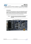
UM1614
User manual
STEVAL- IME002Vx demonstration boards
based on the HM301D and STM32
Introduction
The STEVAL-IME002Vx represent the family of demonstration boards designed around the
new HM301D diagnostic quality analog front-end device for bio-electric sensors and bioimpedance measurements.
This family of boards consists of two demonstration boards: STEVAL-IME002V1 and
STEVAL-IME002V2 designed to demonstrate the use of the HM301D in, respectively,
Electrocardiographs (ECGs) (or patient monitoring systems) and Automated External
Defibrillator (AED) configurations.
The boards also host a 32-bit microcontroller of the STM32 family which manages the SPI
protocol of the HM301D and the USB communication from/to the PC. Both boards can be
easily used with a graphical user interface to demonstrate all the different configurations.
Warning:
These boards must be used only in laboratories and
development environments. This product must never be
connected to the human body.
Figure 1. STEVAL-IME002Vx board
May 2014
DocID024296 Rev 1
1/33
www.st.com
Contents
UM1614
Contents
1
2
3
Overview . . . . . . . . . . . . . . . . . . . . . . . . . . . . . . . . . . . . . . . . . . . . . . . . . . 3
1.1
Features . . . . . . . . . . . . . . . . . . . . . . . . . . . . . . . . . . . . . . . . . . . . . . . . . . . 3
1.2
Demonstration software . . . . . . . . . . . . . . . . . . . . . . . . . . . . . . . . . . . . . . . 3
Hardware layout and configuration . . . . . . . . . . . . . . . . . . . . . . . . . . . . . 4
2.1
Power supply . . . . . . . . . . . . . . . . . . . . . . . . . . . . . . . . . . . . . . . . . . . . . . . 6
2.2
MCU . . . . . . . . . . . . . . . . . . . . . . . . . . . . . . . . . . . . . . . . . . . . . . . . . . . . . . 7
2.2.1
Reset of MCU . . . . . . . . . . . . . . . . . . . . . . . . . . . . . . . . . . . . . . . . . . . . . 7
2.2.2
SPI daisy chain . . . . . . . . . . . . . . . . . . . . . . . . . . . . . . . . . . . . . . . . . . . . 7
2.3
Electrodes connector and protection . . . . . . . . . . . . . . . . . . . . . . . . . . . . 10
2.4
HM301D devices and their configuration . . . . . . . . . . . . . . . . . . . . . . . . . 12
Board connectors . . . . . . . . . . . . . . . . . . . . . . . . . . . . . . . . . . . . . . . . . . 15
3.1
USB . . . . . . . . . . . . . . . . . . . . . . . . . . . . . . . . . . . . . . . . . . . . . . . . . . . . . 15
3.2
User LED and button . . . . . . . . . . . . . . . . . . . . . . . . . . . . . . . . . . . . . . . . 15
3.3
STM32 SWD connector . . . . . . . . . . . . . . . . . . . . . . . . . . . . . . . . . . . . . . 16
3.4
ECG connector . . . . . . . . . . . . . . . . . . . . . . . . . . . . . . . . . . . . . . . . . . . . . 16
3.5
Extra connector . . . . . . . . . . . . . . . . . . . . . . . . . . . . . . . . . . . . . . . . . . . . 18
Appendix A Schematics . . . . . . . . . . . . . . . . . . . . . . . . . . . . . . . . . . . . . . . . . . . . . 19
Appendix B Bill of material . . . . . . . . . . . . . . . . . . . . . . . . . . . . . . . . . . . . . . . . . . 24
Appendix C ECG cable . . . . . . . . . . . . . . . . . . . . . . . . . . . . . . . . . . . . . . . . . . . . . . 31
4
2/33
Revision history . . . . . . . . . . . . . . . . . . . . . . . . . . . . . . . . . . . . . . . . . . . 32
DocID024296 Rev 1
UM1614
Overview
1
Overview
1.1
Features
• Two power supply options: USB connector and external power connector
• Up to three HM301D devices: 12-lead ECG with bio-impedance measurement
• STG3692 low-voltage high-bandwidth quad SPDT switch to manage the HM301D SPI
• STM32F103CBT6: low-power high-performance 32-bit microcontroller powered by ARM®
Cortex™-M3
• ESDALCL6-2SC6 provides ESD protection with very low capacitance
• USB 2.0 full-speed connection
• SWD/JTAG connector to program the MCU
• 37 debug test points to interact electrically with the ICs mounted on the board
• Reset button
• User LED and pushbutton
• Graphical user interface to manage the HM301D and display data outputs
• Device Firmware Upgrade (DFU) procedure for easy upgrades of the STM32 firmware
1.2
Demonstration software
To facilitate user development and data analysis, the STEVAL-IME002Vx demonstration
boards include a graphical user interface to display data outputs, as well as a firmware
library for easy development of customized applications. The latest version of the firmware
package and PC graphical user interface can be downloaded from the web page:
www.st.com/evalboards
DocID024296 Rev 1
3/33
33
Hardware layout and configuration
2
UM1614
Hardware layout and configuration
The STEVAL-IME002Vx demonstration boards have been designed to manage up to three
HM301D devices in an SPI daisy chain. On the STEVAL-IME002V1, an STG3692 (lowvoltage high-bandwidth quad SPDT switch) manages the switch between the three possible
configurations of one, two or three devices entitled U1, U2, and U3 on the board. Only daisy
chain configurations are possible, in other words, it is not possible to have U2 and U3 active
without U1. The allowable sequences are U1, U1 and U2, U1 and U2 and U3 in this order.
Any HM301D input is protected by an ESD protection device, ESDALCL6-2SC6, compliant
with the IEC61000-4-2 level 4 standard.
The hardware block diagram, in Figure 2, illustrates the logical connections between all the
components on the board, while Figure 4 shows the placement of components on the board.
Specifically, the logic connection between the STM32F103CBT6 peripherals and the
HM301Ds is shown in Figure 3, where the master of the SPI is the STM32F103CBT6
microcontroller that manages the SPI switch path (through STG3692), closing the SDO
signals to the MCU. Further details on the SPI chain will be provided in Section 2.2.2.
Figure 2. Block diagram
4/33
DocID024296 Rev 1
UM1614
Hardware layout and configuration
Figure 3. SPI daisy chain
Figure 4. Layout - top layer
DocID024296 Rev 1
5/33
33
Hardware layout and configuration
2.1
UM1614
Power supply
The STEVAL-IME002Vx includes a low-noise voltage regulator (LD59015) to provide 3.3 V
to the entire board.
The board can be powered by the USB cable, supplying +5 V provided by the PC. No other
power supply is needed. When the USB port is connected, the +5 V is automatically
supplied to the board and the LED D1 lights up.
The USB port (2.0 full-speed, 12 Mb/s) is protected by U12 (USBUF02W6) which is a
monolithic application-specific device dedicated to ESD protection for the USB port. It
guarantees compliance with the IEC 61000-4-2 level 4 standard (15 kV air discharge, 8 kV
contact discharge).
The user can supply the HM301D by using an external power supply which can be useful to
test the HM301D in the range 2.7 - 3.6 V, as indicated in the device datasheet.
In order to do this, two simple steps have to be followed:
1.
Remove R66 (see Figure 5)
2.
Connect the external power supply to AVDD (test pad 19) and GND test points
However, the user can test the HM301D over the entire supply voltage range (1.62 - 3.6 V),
but without using the STM32 mounted on the board. To bypass the microcontroller, a further
step is needed:
3.
Remove R70, R71, R72 and R73 (see Figure 5)
In this way, the SPI communication channel between the STM32 and HM301D is interrupted
and the HM301D devices have to be driven by external signals applied to the test pads 33,
34, 35 and 36.
Warning:
The user must verify the voltage polarity as the circuit is not
protected in case of reverse polarity applied to these pads
(33, 34, 35, and 36).
Figure 5. Modifications in order to use an external power supply
Note:
6/33
Do NOT use 3.3 V pad (test point 17) to apply an external power supply.
DocID024296 Rev 1
UM1614
2.2
Hardware layout and configuration
MCU
The STEVAL-IME002Vx demonstration board hosts an STM32F103CBT6.
This microcontroller is part of the STM32 medium-density device family, generically the
STM32F103xx performance line family incorporates the high-performance ARM® Cortex™M3 32-bit RISC core operating up to 72 MHz, high-speed embedded memories (Flash
memory up to 1Mbytes and SRAM up to 80 kbytes), and an extensive range of enhanced
I/Os and peripherals connected to two APB buses.
All devices offer three 12-bit ADCs, four general-purpose 16-bit timers plus one PWM timer,
as well as standard and advanced communication interfaces: up to two I2Cs, three SPIs,
five USARTs, a USB and an SDIO.
The STM32F103xx performance line family operates from a 2.0 to 3.6 V power supply. It is
available in both the -40 to +85 °C temperature range and the -40 to +105 °C extended
temperature range. A comprehensive set of power-saving modes allows designing lowpower applications.
The complete STM32F103xx performance line family includes devices in 5 different
package types: from 36 pins to 100 pins. Please refer to the datasheet and reference
manual for details.
The STM32F103CBT6 present on the board is a medium-density member of the
STM32F103 product family, it embeds 128 kbyte of Flash and 20 kbyte of SRAM in a small
LQFP48 package (7x7 mm).
2.2.1
Reset of MCU
To reset the STM32F103 two sources are available:
•
Reset pushbutton SW1
•
Debugging tool from SWD/JTAG connector J1
The jumper JP1 enables reset of the STM32F103CBT6 embedded JTAG TAP controller
each time a system reset occurs. JP1 connects the TRST signal from the JTAG connection
with the system reset signal RESET#. Default setting: not fitted.
2.2.2
SPI daisy chain
The SPI daisy chain illustrated in Figure 3 is managed by the SPI peripheral of the STM32.
To extract the ECG data with the maximum throughput, this peripheral is configured as
follows:
•
Clock rate at 9 MHz
•
Transfer frame format selected at 16-bit
•
Data order with MSB first
•
Clock polarity set to high
•
Clock phase set on second edge
•
Reception buffer synchronized with internal DMA
The STM32 also manages the STG3692 switch to select the number of HM301D devices to
be connected on the board (only for STEVAL-IME002V1).
DocID024296 Rev 1
7/33
33
Hardware layout and configuration
UM1614
The STG3692 pin connections and its internal diagram are depicted in Figure 6, the truth
table is shown in Table 1. The two Selection pins 1-2SEL and 3-4SEL control Switch 1 and
2, and 3 and 4 respectively.
Table 1. Truth table of STG3692
SEL
Switch S1
Switch S2
H
ON
OFF
L
OFF
ON
Figure 6. Pin connections of STG3692
Figure 7 on page 9 illustrates the SPI routing between the STM32 and the HM301D. The
SPI MOSI signal is connected directly from the STM32 to the HM301D master, while the SPI
MISO is routed through the STG3692 SPDT switch. However, the SPI clock and SPI CS
from the microcontroller are connected to the SPC and CS pins of each HM301D device. As
in Figure 7, on the STEVAL-IME002V1 the four switches enable the three possible
configurations: one HM301D, two HM301D (one master and one slave) or three HM301D
(one master and two slaves). Only daisy chain configurations are possible. In other words
with the three HM301D present on the board (U1, U2 and U3), it is not possible to have U2
and U3 active without U1. The allowed sequences are U1, U1 and U2, U1 and U2 and U3 in
this order. Instead, on the STEVAL-IME002V2 only U1 is mounted and it is the only device
to be addressed by STM32.
The STM32 selects one device by adopting these commands:
–
ADAMO_STG3692_Set_SelectionON(STG3692_12_SEL)
–
ADAMO_STG3692_Set_SelectionOFF(STG3692_34_SEL)
since it sets the 1-2SEL pin and resets the 3-4SEL. In this way, SDO of the HM301D master
is connected to MISO of the STM32 and SDO of the HM301D slaves are inactive.
Otherwise, the STM32 selects two devices by adopting these commands:
8/33
–
ADAMO_STG3692_Set_SelectionOFF(STG3692_12_SEL);
–
ADAMO_STG3692_Set_SelectionON(STG3692_34_SEL);
DocID024296 Rev 1
UM1614
Hardware layout and configuration
since it resets the 1-2SEL pin and sets the 3-4SEL. In this way, the SDO of the HM301D
master is connected to the SDI of the first HM301D Slave and, its SDO is connected to the
MISO of the STM32. HM301D Slave 2 is inactive.
Finally, the STM32 selects three devices by adopting these commands:
–
ADAMO_STG3692_Set_SelectionOFF(STG3692_12_SEL);
–
ADAMO_STG3692_Set_SelectionOFF(STG3692_34_SEL);
since it resets both the 1-2SEL and the 3-4SEL. In this way, the SDO of the HM301D master
is connected to the SDI of the first HM301D slave, its SDO is connected to SDI of the
second HM301D slave and, the latter SDI is connected to the MISO of the STM32.
Figure 7. SPI daisy chain routed through the STG3692
DocID024296 Rev 1
9/33
33
Hardware layout and configuration
2.3
UM1614
Electrodes connector and protection
The STEVAL-IME002Vx board can be connected to a Patient Simulator by using its
standard female D-SUB 15 connector. The user can adopt the recommended ECG cable
indicated in Appendix CAppendix C.
The schematic of the connection of the electrodes with the HM301Ds is illustrated in
Figure 8 and 9. Figure 8 shows the schematic of the ECG connector and filter while Figure 9
shows the ESD protection. The 10 kohm series resistor limits the current flowing to the
ESDALCL6-2SC6 in case of defibrillator discharge. However, the 10 kohm resistors are not
sized to sustain a defibrillator shock, but their presence allows testing the performance of
the HM301D as if it were protected equipment. After the resistors, the entire tracks are
protected by a series of ESDALC6-2SC6 (U15, U16, U17, U18, U19, U20, U21 and U22).
The ESD protection devices used are compliant with the IEC 61000-4-2 level 4 standard
(15 kV air discharge, 8 kV contact discharge).
Figure 8. ECG connectors
1
ECG_RA
1
2
U5_8
1
3
R60
2
1
2
10K
AVDD
1
2
47pF
1
10K
CIN
AVDD
47pF
2
10K
GND
ECG_LL
2
R39
1
RL
2
Footprint 0603
To be mounted only on V2
1
RL
ECG_RL
CIP
RA
LA
RL
1 U5_7
41
1 U5_8
42
1 U5_9
43
1 U5_10
44
1 U5_14
45
R62
50M
Footprint 0603
1
CIN
ECG_RA
R27 (1-2); R28 (1-2); R52 (NM); R60 (2-3)
R27 (1-2); R28 (2-3); R52 (1-2); R60 (1-2)
DocID024296 Rev 1
VREF
3
2
CI_REF
VREF
R51
10K
CIN
R61
50M Footprint 0603
R65
50M
1
1
ECG_LA
2
R37 10K
V4
R49
10K
R59
10K
LA
2
CIP
R52
ECG_V1
1
2
R58
10K
2
10K
2
10K
LL
V1
R33
1
CIP
C30
2
2 1
CIN_CONN
C32
R31
R29
2
1
DB15__F-RA
10/33
V3
R28
3
2
2
10K
1
R22
CIP CONN
1
2
10K
V6
10K
R20
2
1
GND
R35
1
1
ECG_V5
1
3
U5_14
STEVAL-IME002V1
STEVAL-IME002V2
ECG_V3
2
1
ELEC_SHD
U5_7
U5_8
U5_9
U5_10
2
RA
1
2
3
4
5
6
7
8
9
10
11
12
13
14
15
R26
ECG_V6
10K
CIN
C
ELEC_V2
ELEC_V3
ELEC_V4
ELEC_V5
ELEC_V6
ELEC_SHD
7
8
ELEC_RA
ELEC_LA
ELEC_LL
ELEC_V1
13
ELEC_RL
15
10K
1
ECG_SHD
R27
2
R18
1
2
R24
U5
ECG_V2
2
V5
10K
V2
R16
1
ECG_V4
UM1614
Hardware layout and configuration
Figure 9. ESD protection
The connector section can be configured by changing the R0 positioning on the resistor
pads indicated in Table 2.
Table 2. Filter configuration options
STEVAL-IME002V1
STEVAL-IME002V2
To connect the cable shield to
1-2
pin 13 (SD - driver output of the
shield cable) of the HM301D
(default)
R27
master device.
ELEC_SHD
To connect the cable shield to
2-3
ground.
To connect the cable shield to
1-2
pin 13 (SD - driver output of the
(default) shield cable) of the HM301D
master device.
To connect the current injection
positive pin to pin 8 of the ECG
connector
To connect the current injection
1-2
positive pin to pin 8 of the ECG
(default) connector
1-2
R28
CIP_CONN
R52
CI_REF
R60
CIN_CONN
To connect the current injection
2-3
positive pin to the right arm pin
(default) of the ECG connector
1-2
Not mounted
2-3
Not mounted
1-2
To connect the current injection
negative pin to the shield pin of
the ECG connector
2-3
To connect the current injection
(default) negative pin to the left arm pin
of the ECG connector
DocID024296 Rev 1
2-3
2-3
To connect the cable shield to
ground.
To connect the current injection
positive pin to the right arm pin
of the ECG connector
1-2
CI reference set at AVDD / 2
(default)
2-3
CI reference set at VREF
To connect the current injection
1-2
negative pin to the shield pin of
(default) the ECG connector
2-3
To connect the current injection
negative pin to the left arm pin
of the ECG connector
11/33
33
Hardware layout and configuration
2.4
UM1614
HM301D devices and their configuration
The STEVAL-IME002Vx boards have been designed around the HM301D in order to allow
the evaluation of the characteristics of the HM301D for their use in ECG/AED systems. The
STEVAL-IME002V1 has been created to work with one, two or three HM301D devices. In
multi-chip configurations the SPI will be configured as a daisy chain SPI, connecting the
data output of any device to the data input of the following device, as explained in
Section 2.2.2.
To address a broad range of applications, some channels of the three HM301Ds can be
connected to the electrodes as bipolar configuration and some as unipolar. At the output of
the channel, the bipolar configuration gives the voltage difference between 2 electrodes.
Otherwise, the unipolar configuration reads the difference between the single electrode and
the WCT reference voltage.
To evaluate the different modes of operation of the HM301D devices, the demonstration
boards allow connecting the first HM301D (U1) in bipolar or unipolar configuration, while the
other HM301Ds (U2 and U3) are always connected in unipolar mode.
Specifically on the STEVAL-IME002V1, U1 is configured to acquire the Einthoven
equilateral triangle. Its vertices's are LA (left arm), RA (right arm), and LL (left leg) and are
directly connected to U1. Moreover, the RL (right leg) is used as a reference electrode for
potential and is connected to pin 9 of U1. In this arrangement, the electrocardiographic
frontal limb leads could be easily retrieved. In fact, lead I is the potential difference between
LA and RA, lead II is the potential difference between LL and RA and, lead III is the potential
difference between LL and LA. The connection is controlled by the resistors R1, R2 and R3,
see Table 3.
Most of the traditional clinical ECG machines use a single channel amplifier and recording
system with a multi-position switch to select the desired lead connection. The HM301Ds on
the STEVAL-IME002V1 permit the recording of all lead connections (I, II, III, V1, V2, V3, V4,
V5, and V6) and apply it to the bio-potential amplifier through the parameter setting of a
Graphical User Interface. The ECG leads can be also recorded on the user’s PC.
If present, the electrodes V1, V2 and V3 are connected to the U2 in unipolar mode and, the
electrodes V4, V5 and V6 to the U3 in unipolar mode. All the connections of the U2 and U3
devices are unipolar and are referred to the WCT signal of the master (U1) device.
Specifically on the STEVAL-IME002V2, only U1 is mounted on the board and it is configured
to acquire only lead I, the potential difference between LA and RA.
.
Table 3. Input configuration of first HM301D
STEVAL-IME002Vx configuration
R1
U1 - IN1
R2
U1 - IN2
1-2
(default in V1)
Unipolar mode
2-3
(default in V2)
Bipolar mode
1-2
Unipolar mode
(default in V1,
not mounted in V2)
2-3
12/33
Bipolar mode
DocID024296 Rev 1
Result
WCT shorted with IN1_P
LA shorted with IN1_P
WCT shorted with IN2_P
LL shorted with IN2_P
UM1614
Hardware layout and configuration
Table 3. Input configuration of first HM301D (continued)
STEVAL-IME002Vx configuration
R3
U1 - IN3
1-2
Unipolar mode
(default in V1,
not mounted in V2)
2-3
R15
Result
WCT shorted with IN3_P
Bipolar Mode
RA shorted with IN3_P
R0 in V1,
not mounted in V2
LA shorted with IN2_N
To synchronize the three devices, an external crystal oscillator is used. The Q1 quartz is
soldered on the board and connected to the master device (U1). The clock is generated in
U1 and delivered to the other devices.
All the common ECG configurations listed in Table 4 can be achieved with the STEVALIME002Vx demonstration boards.
Table 4. STEVAL-IME002Vx common ECG configurations
Application
Electrodes
Connection
Channels
Devices
Board
– Standard 129 + RL
lead ECG
2 bipolar + 6
unipolar
8
3 x HM301D
STEVALIME002V1
– Standard 129 + RL
lead ECG
9 unipolar
9
3 x HM301D
STEVALIME002V1
– Interpolated
12-lead
using a 6wire cable
5 + RL
2 bipolar + 2
unipolar
4
2 x HM301D
STEVALIME002V1
– Interpolated
12-lead
using a 6wire cable
5 + RL
5 unipolar
5
2 x HM301D
STEVALIME002V1
– 5-lead wire
/EASI
4 + RL
2 bipolar + 1
unipolar
3
1 x HM301D
STEVALIME002V1
– 5-lead wire /
EASI
4 + RL
4 unipolar
4
2 x HM301D
STEVALIME002V1
– Einthoven's
Triangle
3 + RL
2 bipolar
2
1 x HM301D
STEVALIME002V1
– Einthoven's
Triangle
3 + RL
3 unipolar
2
1 x HM301D
STEVALIME002V1
– Rhythm
2
1 bipolar
1
1 x HM301D
STEVALIME002V2
– Automated
External
Defibrillator
2
1 bipolar
1
1 x HM301D
STEVALIME002V2
DocID024296 Rev 1
13/33
33
Hardware layout and configuration
UM1614
The STEVAL-IME002Vx and the HM301D offer a further functional mode to be configured
through the TM pins (see Section 6.7 of the HM301D datasheet), the two modes available
are:
•
Operating mode with internally generated POR
•
Operating mode with external Enable
As shown in Figure 8 on page 10, to obtain these settings, R11 and R12 resistors can be
placed as indicated in Table 5.
Table 5. TM configuration
Resistor
Note:
14/33
Default
TM0
R12
2-3
TM1
R11
1-2
Optional
Operating
mode with
Enable
provided by
STM32
2-3
Operating
mode with
internally
generated
POR
2-3
It is recommended to not change this configuration on the STEVAL-IME002Vx board, the
STM32F103CBT6 is programmed to generate the POR signal.
DocID024296 Rev 1
UM1614
Board connectors
3
Board connectors
3.1
USB
The STEVAL-IME002Vx are provided with USB 2.0 compliant full-speed communication via
a USB type mini-B receptacle connector (CN1), with dedicated EMI filter and line
termination through USBUF02W6 (U5). The PA10 pin of the STM32F103 is used for the
software connection/disconnection of the USB cable. The MCU pins shall be configured in
output push-pull mode: when high, the USB communication is enabled, when low, it is
disabled.
Figure 10. USB mini-B connector (CN1) and schematics
Table 6. USB mini-B connector pinout
3.2
Pin number
Description
1
Vbus (power)
2
DM (PA11)
3
DP(PA12)
4
N.C.
5
Ground
User LED and button
In the STEVAL-IME002Vx demonstration board, one LED D2 and one pushbutton SW2 are
available for the user's application. The embedded firmware uses the LED to indicate the
Acquisition phase to the user, while the pushbutton is used only to exploit the embedded
Device Firmware Upgrade (refer to AN4267 available from www.st.com).
Table 7. User LED and GPIO button
Device
MCU GPIO
D2
PA3
SW2
PB0
DocID024296 Rev 1
15/33
33
Board connectors
3.3
UM1614
STM32 SWD connector
The STM32F103CBT6 can be programmed through the J1 connector, its pinout is described
in Figure 11 and Table 8.
Figure 11. SWD (J1)
Table 8. JTAG/SWD connector pinout
3.4
Pin number
Description
1
MCU_3V3
2
JTMS
3
GND
4
JTCK
5
GND
6
JTDO
7
GND
8
JTDI
9
GND
10
RESET#
ECG connector
The STEVAL-IME002Vx demonstration boards can be connected to a Patient Simulator
through a DB15 connector, its pinout is described in Figure 12 and Table 9.
Figure 12. ECG connector
16/33
DocID024296 Rev 1
UM1614
Board connectors
Table 9. ECG connector pinout
Pin
Number
STEVALIME002Vx
Connection
IEC Code 1
(usually
European)
IEC Code 2
(usually
American)
1
ECG_V2
C2
V2
Fourth intercostal space at right
border of sternum
2
ECG_V3
C3
V3
Fifth rib between C2/V2 and C4/V4
3
ECG_V4
C4
V4
Fifth intercostal space on left
midclavicular line
4
ECG_V5
C5
V5
Left anterior axillary line at the
horizontal level of C4
5
ECG_V6
C6
V6
Left midaxillary line at the
horizontal level of C4
6
ELEC_SHIELD
7
CIN
8
CIP
9
R
RA
Right arm
10
L
LA
Left arm
11
F
LL
Left leg
12
C1
V1
Single movable chest electrode
N
RL
Right leg (neutral electrode)
13
Not Connected
14
15
Position on Body
Not Connected
DocID024296 Rev 1
17/33
33
Board connectors
3.5
UM1614
Extra connector
In order to facilitate the connection of the user’s own Patient Simulator, five extra connection
pins have been provided on the board, see Figure 13 and Table 10.
Figure 13. Extra connection pins
Table 10. Extra connection pinout
Note:
18/33
Pin number
Description
1
CIN
2
CIP
3
RA
4
LA
5
RL
These pins are mutually exclusive with the ECG connector. Avoid plugging signals into
these pins and the ECG connector at the same time, or use these pins only to show signals
on an oscilloscope.
DocID024296 Rev 1
UM1614
Appendix A
Schematics
Schematics
Figure 14. HM301D section
DocID024296 Rev 1
19/33
33
Schematics
UM1614
Figure 15. ECG connectors
1
3
1
2
U5_8
1
1
C32
R31
2
10K
AVDD
1
2
1
10K
CIN
47pF
2
2
1
Footprint 0603
To be mounted only on V2
RL
2
ECG_RL
RA
LA
RL
1 U5_7
41
1 U5_8
42
1 U5_9
43
1 U5_10
44
1 U5_14
45
R62
50M
Footprint 0603
1
CIP
ECG_RA
R27 (1-2); R28 (1-2); R52 (NM); R60 (2-3)
R27 (1-2); R28 (2-3); R52 (1-2); R60 (1-2)
Figure 16. ESD protection
DocID024296 Rev 1
3
2
CI_REF
R51
10K
VREF
CIN
R61
50M Footprint 0603
R65
50M
1
RL
2
VREF
1
GND
ECG_LL
2
10K
1
R59
10K
LA
ECG_LA
1
CIP
R49
10K
R52
ECG_V1
R39
2
R58
10K
AVDD
2
10K
2
10K
LL
V1
R33
1
CIP
C30
2
2 1
47pF
R29
2
R60
2
CIN_CONN
CIN
V4
V3
R28
2
ECG_RA
3
1
R37 10K
10K
V6
2
10K
CIP CONN
1
2
1
R22
DB15__F-RA
20/33
ECG_V5
10K
R20
2
1
GND
R35
1
1
1
3
U5_14
STEVAL-IME002V1
STEVAL-IME002V2
ECG_V3
2
1
ELEC_SHD
U5_7
U5_8
U5_9
U5_10
2
RA
1
2
3
4
5
6
7
8
9
10
11
12
13
14
15
R26
ECG_V6
10K
CIN
C
ELEC_V2
ELEC_V3
ELEC_V4
ELEC_V5
ELEC_V6
ELEC_SHD
7
8
ELEC_RA
ELEC_LA
ELEC_LL
ELEC_V1
13
ELEC_RL
15
10K
1
ECG_SHD
R27
2
R18
1
2
R24
U5
ECG_V2
2
V5
10K
V2
R16
1
ECG_V4
UM1614
Schematics
Figure 17. Connectors and buttons
DocID024296 Rev 1
21/33
33
Schematics
UM1614
Figure 18. Microcontroller
22/33
DocID024296 Rev 1
UM1614
Schematics
Figure 19. Power management
DocID024296 Rev 1
23/33
33
Bill of material
Appendix B
UM1614
Bill of material
Table 11. STEVAL-IME002V1
Item
Qty
Reference
Part / Value
Package
Manufacturer
Manufacturer’s
ordering code /
orderable part
number
Supplier
Supplier’s
ordering
code
ADAMO demonstration board
1
1
CN1
Molex
54819-0572
RS
RS: 515-1995
23
C1, C2,
C3, C4,
C5, C6,
C9, C11,
C13, C14,
C15, C16,
C41, C43,
C44, C45,
C50, C70,
C72, C118,
C119,
C120,
C121
100nF
SMD
0603
MURATA
GRM188R71H10
4KA93D
RS
RS: 624-2480
3
23
R7, R10,
R13, R14,
R17, R21,
R23, R49,
R51, R52,
R58, R59,
R61, R62,
R65, R78,
C7, C8,
C17, C18,
C60, C61,
C71
N.M.
SMD
0603
N.M.
4
2
C10, C12
27pF
SMD
0603
MURATA
5
2
C30, C32
0
SMD
0603
Any
6
1
C42
4.7nF
SMD
0603
MURATA
GRM188R71H47
2KA01D
RS
RS: 204-0741
7
1
C46
10µF 6.3V
SMD
0805
AVX
TAJR106K006R
RS
RS: 405-9517
8
1
C64
1µF 10V
SMD
0603
MURATA
GRM188F51A10
5ZA01D
RS
RS:545-4317
9
2
C51, C65
1µF 6.3V
SMD
0603
AVX
TACL105M006R
RS
RS: 405-7779
10
1
D1
KP2012MGC
RS /
Farnell
RS: 466-3778
Farnell:
8529906
2
24/33
USB_miniB
POWER_ON
LED 0806 Kingbright
DocID024296 Rev 1
N.M.
GQM1885C1H27
0JB01D
RS
RS:647-7349
Any
UM1614
Bill of material
Table 11. STEVAL-IME002V1 (continued)
Reference
Part / Value
Package
Manufacturer
Manufacturer’s
ordering code /
orderable part
number
Supplier
Supplier’s
ordering
code
KP2012MGC
RS /
Farnell
RS: 466-3778
Farnell:
8529906
Item
Qty
11
1
D2
ACQ
12
1
JP1
Jumper
THR
(spacing
2.54)
Any
13
1
J1
SWD/JTAG
(male connector
10-pin 2x5)
THR
(spacing
1.27)
SAMTEC
FTSH-105-01-FD-K
Any
14
1
L1
30 Ohm 3A
30 Ohm
3A
SMD 0805
Wurth Electronics
74279206
RS
RS: 358-6765
15
1
Q1
FOXSLF040
See
datasheet
FOXSLF040
RS
RS: 547-6171
16
1
R1 (IN1:
pos. 1-2)
0 Ohm
SMD
0603
Any
Any
17
1
R2 (IN2:
pos. 1-2)
0 Ohm
SMD
0603
Any
Any
18
1
R3 (IN3:
pos. 1-2)
0 Ohm
SMD
0603
Any
Any
19
2
R74, R77
SEL
SMD
0603
Not
mounted
Not
mounted
20
18
R4, R5,
R6, R8,
R9, R15,
R19, R25,
R30, R54,
R63, R64,
R70, R71,
R72, R73,
R75, R76
0 Ohm
SMD
0603
Any
Any
21
1
R66
0 Ohm
SMD
0805
Any
Any
22
1
R11 (TM1:
pos. 2-3)
0 Ohm
SMD
0603
Any
Any
23
1
R12 (TM1:
pos. 1-2)
0 Ohm
SMD
0603
Any
Any
LED 0806 Kingbright
DocID024296 Rev 1
Any
25/33
33
Bill of material
UM1614
Table 11. STEVAL-IME002V1 (continued)
Manufacturer’s
ordering code /
orderable part
number
Part / Value
Package
Manufacturer
19
R16, R18,
R20, R22,
R24, R26,
R29, R31,
R33, R35,
R37, R39,
R41, R42,
R44, R45,
R46, R47,
R48
10k
SMD
0603
Any
Any
25
1
R27
(ELEC_SH
D pos.1-2)
0 Ohm
SMD
0603
Any
Any
26
1
R28
(CIP_CON
N pos. 2-3)
0 Ohm
SMD
0603
Any
Any
27
1
R60
(CIN_CON
N pos. 2-3)
0 Ohm
SMD
0603
Any
Any
28
2
R40, R57
56R
SMD
0603
Any
Any
29
1
R43
1M
SMD
0603
Any
Any
30
2
R67, R68
4k7
SMD
0603
Any
Any
31
2
SW1, SW2
SW
PUSHBUTTONDPST
32
3
U1,U2,U3
HM301D
See
datasheet
ST
ST
33
1
U4
STG3692
See
datasheet
ST
ST
34
1
U5
DB15__F-RA
TE
DIGIKEY
35
1
U10
36
1
U12
37
1
U13
Item
Qty
Reference
24
26/33
C&K
Y78B22110FP
RS
STM32F103CB
See
T6
datasheet
ST
USBUF02W6
See
datasheet
ST
ST
LD59015C33R
See
datasheet
ST
ST
DocID024296 Rev 1
STM32F103CBT
6
Supplier
ST
Supplier’s
ordering
code
RS: 505-9186
A32076-ND
UM1614
Bill of material
Table 11. STEVAL-IME002V1 (continued)
Item
38
39
Qty
8
1
Manufacturer’s
ordering code /
orderable part
number
Supplier’s
ordering
code
Reference
Part / Value
Package
Manufacturer
U15, U16,
U17, U18,
U19, U20,
U21, U22
ESDALCL62SC6
See
datasheet
ST
ST
Murata
RS /
Digikey /
Farnell
RS: 283-961,
DigiKey: 4901195-1-ND,
Farnell:
1615352
Supplier
Supplier’s
ordering
code
Y1
8 MHz
CSTCE8M0G55R0
Supplier
Table 12. STEVAL-IME002V2
Item Qty Reference
Part / Value
Package
Manufacturer
Manufacturer’s
ordering code /
orderable part
number
ADAMO demonstration board
1
1
CN1
13
C1, C2,
C3, C4,
C41, C43,
C44, C45,
C50, C70,
C118,
C119,
C120
100 nF
3
36
R4, R5,
R7, R8,
R9, R10,
R13, R14,
R15, R16,
R17, R18,
R20, R24,
R25, R26,
R30, R35,
R63, R64,
C5, C6,
C7, C8,
C9, C11,
C13, C14,
C15, C16,
C17, C18,
C60, C61,
C71, C72
4
2
C10, C12
2
USB_miniB
Molex
54819-0572
RS
RS: 515-1995
SMD
0603
MURATA
GRM188R71H10
4KA93D
RS
RS: 624-2480
N.M.
SMD
0603
N.M.
N.M.
N.M.
27 pF
SMD
0603
MURATA
GQM1885C1H27
0JB01D
RS
DocID024296 Rev 1
RS:647-7349
27/33
33
Bill of material
UM1614
Table 12. STEVAL-IME002V2 (continued)
Item Qty Reference
Part / Value
Package
Manufacturer
Manufacturer’s
ordering code /
orderable part
number
Supplier
Supplier’s
ordering
code
5
2
C30, C32
47 pF
SMD
0603
MURATA
GRM1885C1H47
0JA01D
RS
RS: 545-4121
6
1
C42
4.7 nF
SMD
0603
MURATA
GRM188R71H47
2KA01D
RS
RS: 204-0741
7
1
C46
10 µF 6.3 V
SMD
0805
AVX
TAJR106K006R
RS
RS: 405-9517
8
1
C64
1 µF 10 V
SMD
0603
MURATA
GRM188F51A105
ZA01D
RS
RS:545-4317
9
2
C51, C65
1 µF 6.3 V
SMD
0603
AVX
TACL105M006R
RS
RS: 405-7779
10
1
D1
POWER_ON
LED 0806 Kingbright
KP2012MGC
RS /
Farnell
RS: 466-3778
Farnell:
8529906
11
1
D2
ACQ
LED 0806 Kingbright
KP2012MGC
RS /
Farnell
RS: 466-3778
Farnell:
8529906
12
1
JP1
JUMPER
THR
(spacing
2.54)
Any
13
1
J1
SWD/JTAG (male
connector
10-pin 2x5)
THR
(spacing
1.27)
SAMTEC
FTSH-105-01-FD-K
Any
14
1
L1
30 Ohm 3 A
30 Ohm
3A
SMD 0805
Wurth Electronics
74279206
RS
RS: 358-6765
15
1
Q1
FOXSLF040
See
datasheet
FOXSLF040
RS
RS: 547-6171
16
1
R1 (IN1
pos. 2-3)
0 Ohm
SMD
0603
Any
Any
17
1
R2
N.M.
SMD
0603
N.M.
N.M.
18
1
R3
N.M.
SMD
0603
N.M.
N.M.
19
2
R74, R77
N.M.
SMD
0603
N.M.
20
12
R6, R19,
R21, R23,
R54, R70,
R71, R72,
R73, R75,
R76, R78
0 Ohm
SMD
0603
Any
Any
21
1
R66
0 Ohm
SMD
0805
Any
Any
28/33
DocID024296 Rev 1
Any
UM1614
Bill of material
Table 12. STEVAL-IME002V2 (continued)
Item Qty Reference
Part / Value
Package
Manufacturer
Manufacturer’s
ordering code /
orderable part
number
Supplier
22
1
R11 (TM1
pos. 2-3)
TM1
SMD
0603
Any
Any
23
1
R12 (TM0
pos. 1-2)
TM0
SMD
0603
Any
Any
24
17
R22, R29,
R31, R33,
R37, R39,
R41, R42,
R44, R45,
R46, R47,
R48, R49,
R51, R58,
R59
10 k
SMD
0603
Any
Any
25
1
R27
(ELEC_SH
D pos. 1-2)
0 Ohm
SMD
0603
Any
Any
26
1
R28
(CIP_CON
N pos. 1-2)
0 Ohm
SMD
0603
Any
Any
27
1
R52
(CI_REF
pos. 1-2)
0 Ohm
SMD
0603
Any
Any
28
1
R60
(CIN_CON
N pos. 1-2)
0 Ohm
SMD
0603
Any
Any
29
2
R40, R57
56R
SMD
0603
Any
Any
30
1
R43
1M
SMD
0603
Any
Any
31
3
R61, R62,
R65
50 M
SMD
0603
Any
Any
32
2
R67, R68
4k7
SMD0603
Any
Any
33
2
SW1, SW2
34
1
U1
HM301D
See
datasheet
35
2
U2, U3
HM301D
N.M.
N.M.
N.M.
36
1
U4
STG3692
N.M.
N.M.
N.M.
37
1
U5
DB15__F-RA
38
1
U10
STM32F103CBT6
SW
PUSHBUTTONDPST
C&K
Y78B22110FP
ST
ST
DocID024296 Rev 1
RS: 505-9186
ST
TE
See
datasheet
RS
Supplier’s
ordering
code
DIGIKEY
STM32F103CBT6
A32076-ND
ST
29/33
33
Bill of material
UM1614
Table 12. STEVAL-IME002V2 (continued)
Item Qty Reference
Part / Value
Package
Manufacturer
Manufacturer’s
ordering code /
orderable part
number
Supplier
39
1
U12
USBUF02W6
See
datasheet
ST
ST
40
1
U13
LD59015C33R
See
datasheet
ST
ST
41
5
U18, U19,
U20, U21,
U22
ESDALCL6-2SC6
See
datasheet
ST
ST
42
3
U15, U16,
U17
ESDALCL6-2SC6
N.M.
N.M.
N.M.
Murata
RS /
Digikey /
Farnell
43
30/33
1
Y1
8 MHz
DocID024296 Rev 1
CSTCE8M0G55R0
Supplier’s
ordering
code
RS: 283-961,
DigiKey: 4901195-1-ND,
Farnell:
1615352
UM1614
Appendix C
ECG cable
ECG cable
Figure 20. ECG cable
DocID024296 Rev 1
31/33
33
Revision history
4
UM1614
Revision history
Table 13. Document revision history
32/33
Date
Revision
08-May-2014
1
Changes
Initial release.
DocID024296 Rev 1
UM1614
Please Read Carefully:
Information in this document is provided solely in connection with ST products. STMicroelectronics NV and its subsidiaries (“ST”) reserve the
right to make changes, corrections, modifications or improvements, to this document, and the products and services described herein at any
time, without notice.
All ST products are sold pursuant to ST’s terms and conditions of sale.
Purchasers are solely responsible for the choice, selection and use of the ST products and services described herein, and ST assumes no
liability whatsoever relating to the choice, selection or use of the ST products and services described herein.
No license, express or implied, by estoppel or otherwise, to any intellectual property rights is granted under this document. If any part of this
document refers to any third party products or services it shall not be deemed a license grant by ST for the use of such third party products
or services, or any intellectual property contained therein or considered as a warranty covering the use in any manner whatsoever of such
third party products or services or any intellectual property contained therein.
UNLESS OTHERWISE SET FORTH IN ST’S TERMS AND CONDITIONS OF SALE ST DISCLAIMS ANY EXPRESS OR IMPLIED
WARRANTY WITH RESPECT TO THE USE AND/OR SALE OF ST PRODUCTS INCLUDING WITHOUT LIMITATION IMPLIED
WARRANTIES OF MERCHANTABILITY, FITNESS FOR A PARTICULAR PURPOSE (AND THEIR EQUIVALENTS UNDER THE LAWS
OF ANY JURISDICTION), OR INFRINGEMENT OF ANY PATENT, COPYRIGHT OR OTHER INTELLECTUAL PROPERTY RIGHT.
ST PRODUCTS ARE NOT DESIGNED OR AUTHORIZED FOR USE IN: (A) SAFETY CRITICAL APPLICATIONS SUCH AS LIFE
SUPPORTING, ACTIVE IMPLANTED DEVICES OR SYSTEMS WITH PRODUCT FUNCTIONAL SAFETY REQUIREMENTS; (B)
AERONAUTIC APPLICATIONS; (C) AUTOMOTIVE APPLICATIONS OR ENVIRONMENTS, AND/OR (D) AEROSPACE APPLICATIONS
OR ENVIRONMENTS. WHERE ST PRODUCTS ARE NOT DESIGNED FOR SUCH USE, THE PURCHASER SHALL USE PRODUCTS AT
PURCHASER’S SOLE RISK, EVEN IF ST HAS BEEN INFORMED IN WRITING OF SUCH USAGE, UNLESS A PRODUCT IS
EXPRESSLY DESIGNATED BY ST AS BEING INTENDED FOR “AUTOMOTIVE, AUTOMOTIVE SAFETY OR MEDICAL” INDUSTRY
DOMAINS ACCORDING TO ST PRODUCT DESIGN SPECIFICATIONS. PRODUCTS FORMALLY ESCC, QML OR JAN QUALIFIED ARE
DEEMED SUITABLE FOR USE IN AEROSPACE BY THE CORRESPONDING GOVERNMENTAL AGENCY.
Resale of ST products with provisions different from the statements and/or technical features set forth in this document shall immediately void
any warranty granted by ST for the ST product or service described herein and shall not create or extend in any manner whatsoever, any
liability of ST.
ST and the ST logo are trademarks or registered trademarks of ST in various countries.
Information in this document supersedes and replaces all information previously supplied.
The ST logo is a registered trademark of STMicroelectronics. All other names are the property of their respective owners.
© 2014 STMicroelectronics - All rights reserved
STMicroelectronics group of companies
Australia - Belgium - Brazil - Canada - China - Czech Republic - Finland - France - Germany - Hong Kong - India - Israel - Italy - Japan Malaysia - Malta - Morocco - Philippines - Singapore - Spain - Sweden - Switzerland - United Kingdom - United States of America
www.st.com
DocID024296 Rev 1
33/33
33