1
IntelliVue MP80/90 & D80
Se r vi c e G ui de
IntelliVue Patient Monitor
MP80/90 & D80
Pa tie n t Monit o ring
Part Number M8000-9351K
4535 641 12591
*M8000-9351K*
Table of Contents
1 Introduction
9
Who Should Use This Guide
9
How to Use This Guide
9
Abbreviations
9
Responsibility of the Manufacturer
10
Passwords
11
Warnings and Cautions
11
2 Theory of Operation
Monitor Theory of Operation
13
13
System Boundaries
14
Hardware Building Blocks
15
Data Flow
19
How does the Support Tool Work with the Monitor
23
Monitor Software Block Diagram
24
Block Diagram Legend
25
3 Testing and Maintenance
33
Introduction
33
Terminology and Definitions
34
Recommended Frequency
35
When to Perform Tests
36
Testing Sequence
40
Visual Inspection
41
Before Each Use
41
After Each Service, Maintenance or Repair Event
41
Power On Test
Safety Tests
Warnings, Cautions, and Safety Precautions
Safety Test Procedures
Preventive Maintenance Procedures
Noninvasive Blood Pressure Measurement Calibration
Performance Assurance Tests
41
42
43
44
84
84
84
Basic Performance Assurance Test
84
Full Performance Assurance Test
85
ECG/Resp Performance Test
85
ECG Sync Performance Test
86
SpO2 Performance Test
86
NBP PerformanceTest
87
Invasive Pressure Performance Test
89
3
Temperature Performance Test
90
M3014A Capnography Extension Performance Tests
90
Microstream CO2 Performance Test
93
Spirometry Performance Tests
98
Cardiac Output Performance Test
100
BIS Performance Test
101
Vuelink Performance Test
102
IntelliBridge Performance Test
103
EEG, SvO2 and tcGas Performance Tests
103
Nurse Call Relay Performance Test
103
Power Loss Alarm Buzzer Performance Test (only if Multi-Port Nurse Call Connector Board is installed)
105
IntelliVue 802.11 Bedside Adapter Communication Test
Reporting of Test Results
Carrying Out and Reporting Tests
Evaluation of Test Results
106
107
108
111
Other Regular Tests
112
Touchscreen Calibration
112
Disabling/Enabling Touch Operation
112
Printer Test Report
113
After Installation, Testing or Repair
113
4 Troubleshooting
115
Introduction
115
How To Use This Section
115
Who Should Perform Repairs
115
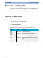
Replacement Level Supported
116
Hardware Revision Check
116
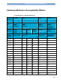
Hardware/Software Compatibility Matrix
117
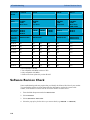
Software Revision Check
118
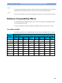
Software Compatibility Matrix
119
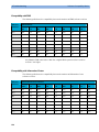
Compatibilty with MMS
119
Compatibilty with FMS
120
Compatibility with Information Center
120
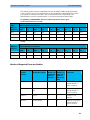
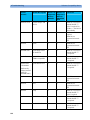
Number of Supported Parameter Modules
121
Obtaining Replacement Parts
123
Troubleshooting Guide
123
4
Checks for Obvious Problems
123
Checks Before Opening the Instrument
124
Troubleshooting Tables
126
Status Log
154
List of Error Codes
156
Troubleshooting with the Support Tool
156
Troubleshooting the Individual Measurements or Applications
157
5 Repair and Disassembly
159
Tools Required
159
MP80/D80/MP90 CMU Disassembly
159
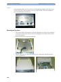
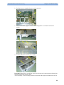
Removing I/O Boards
160
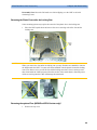
Removing the Top Cover
162
Removing the Plastic Feet and/or the Locking Cam
163
Removing the optional Fans (MP90 Dual CPU Versions only)*
163
Replacing the Second (Independent) Video Board(MP90 Dual CPU Versions only)
164
Removing the Second CPU/Main Board (MP90 Dual CPU Versions only)
165
Accessing the Main CPU or Primary Video Board (MP90 Dual CPU Versions)
167
Replacing the Primary Video Board
168
Removing the Main Board
170
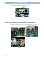
Removing the Power Supply
172
Removing the Speaker (MP80/MP90 only)
174
Removing the Power On/Off Switch
174
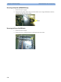
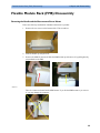
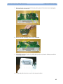
Flexible Module Rack (FMS) Disassembly
Removing the Handle and the Measurement Server Mount
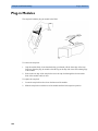
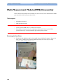
Plug-in Modules
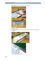
Plug-In Module Disassembly
Multi-Measurement Module (MMS) Disassembly
175
175
180
181
184
Tools required
184
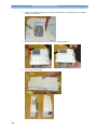
Removing the Front Cover
184
Removing the Mounting Pin
185
Removing the Top Cover
185
Removing the DC/DC Board
186
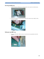
Removing the MSL Flex Assembly
186
Reassembling the MSL Flex Assembly
187
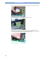
Removing the NBP pump
189
Refitting the new NBP Pump
189
Refitting the DC/DC board
191
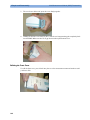
Refitting the Cover
191
Refitting the Front Cover
192
Final Inspection
193
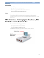
MMS Extensions - Exchanging the Top Cover, MSL Flex Cable and the Dual Link Bar
Exchange Procedures
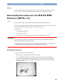
Disassembly Procedures for the M3015A MMS Extension (HW Rev. A)
193
194
205
Removing the Front Cover
205
Refit Procedures for the MMS Extension
209
6 Parts
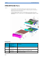
MP80/MP90/D80 Parts
211
212
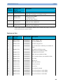
Exchange Parts
212
Replacement Parts
213
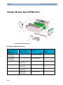
Flexible Module Rack (FMS) Parts
216
5
Exchange and Replacement Parts
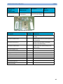
Multi-Measurement Module (MMS) Parts
216
218
MMS Part Number Overview and Identification
218
MMS Firmware Overview
220
MMS Part Numbers - Front Bezel for M3001 #A01 & #A03
221
MMS Part Numbers - Front Bezel for M3001 #A02
221
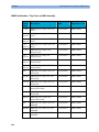
MMS Part Numbers - Top Cover and MSL Assembly
222
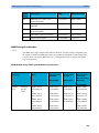
MMS Exchange Part Numbers
223
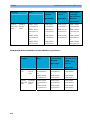
MMS Part Numbers - Label Kits
225
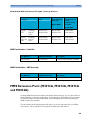
MMS Part Numbers - NBP Assembly
MMS Extension Parts (M3012A, M3014A, M3015A and M3016A)
225
225
MMS Extension Part Numbers - Release Mechanisms
226
MMS Extension Part Numbers - Top Cover, Flex Cable and Link Bar
226
MMS Extension Part Numbers - Front Bezels
226
Exchange Parts List
228
IntelliVue X2 Part Numbers
229
Plug-in Modules Part Numbers
229
Part Number Table
230
Plug-In Modules Replaceable Parts
233
BIS Solution Replaceable Parts
238
BISx Solution Replacable Parts
239
tcpO2/tcpCO2 Module Accessories
240
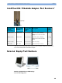
IntelliVue 802.11 Bedside Adapter Part Numbers*
241
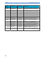
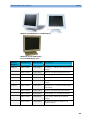
External Display Part Numbers
241
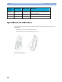
SpeedPoint Part Numbers
244
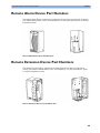
Remote Alarm Device Part Numbers
245
Remote Extension Device Part Numbers
245
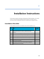
7 Installation Instructions
247
Installation Checklist
247
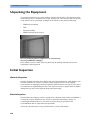
Unpacking the Equipment
248
Initial Inspection
248
Mechanical Inspection
248
Electrical Inspection
248
Claims For Damage and Repackaging
249
Installing the M8008A/M8010A/M8016A CMU
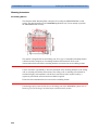
Mounting Instructions
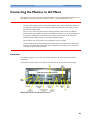
Connecting the Monitor to AC Mains
6
249
250
251
Connections
251
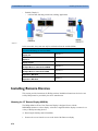
Installing Interface Boards
252
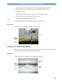
Connection of Devices via the MIB/RS232 Interface G.00.xx or higher
257
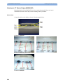
Connection of Devices via the MIB/RS232 Interface (Rev. D.00.58 to F.01.42)
258
Connection of Devices via the MIB/RS232 Interface (Rev. A.10.15 to C.00.90)
258
Connection of MIB Devices (Rev. below A.10.15)
259
Connection of USB Devices
260
Setting Up Multiple Displays
264
Installation of Multiple Displays
264
Configuring Multiple Displays
266
Examples for Multiple Display Use Models
270
Installing Remote Devices
272
Mounting the 15” Remote Display (M8031A)
272
Mounting the 15” Remote Display (M8031B)
273
Mounting the 17” Remote Display (M8033A/B/C)
274
Hardware Settings
277
Flexible Module Rack and/or Multi-Measurement Module
277
Remote Alarm Devices
283
Remote Extension Device
284
PS/2 Keyboard/Mouse
286
Philips Clinical Network (Wired)
286
Philips Clinical Network (Wireless)
286
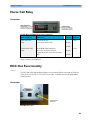
Nurse Call Relay
287
Connections
287
ECG Out Functionality
Connections
Configuration Tasks
287
287
288
Checking Country-Specific Default Settings
289
Setting Altitude, Line Frequency, ECG Cable Colors and Height & Weight Units
289
Setting Altitude and Line Frequency
290
Configuring the Equipment Label
290
Configuring the printer
290
Configuring IP Address, Subnet Mask and Default Gateway
290
Configuration Settings for CSCN Routed Bedside Monitors (RBM)
291
Configuring Routed Bedside Monitors Support
291
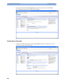
Display Settings
292
IntelliBridge EC10
293
Accessing the IntelliBridge EC10 Service Interface
293
Firmware Upgrade
294
Uploading and Removing Device Drivers
295
Generating and Uploading Clone Files
295
Viewing System Information
296
Handing Over the Monitor
297
8 Site Preparation
Introduction
299
299
Site Planning
299
Roles & Responsibilities
300
M8008A/M8010A/M8016A Site Requirements
302
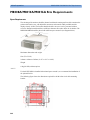
Space Requirements
302
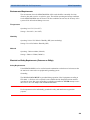
Environmental Requirements
303
7
Electrical and Safety Requirements (Customer or Philips)
303
Remote Device Site Requirements
304
Connecting Non-Medical Devices
305
Multi-Measurement Module (MMS) M3001A, IntelliVue X2 M3002A or Flexible Module Rack (FMS) M8048A305
Remote Displays (M8031A)
310
Remote Displays (M8031B)
311
Remote Displays - M8033A
312
Remote Displays - M8033B
313
Remote Displays - M8033C
314
Remote Alarm Devices
316
Remote Extension Device
317
IntelliBridge
319
Local Printer
319
Philips Medical LAN
319
RS232/MIB/LAN Interface
320
Nurse Call Relay Interface
321
ECG Out Interface
321
9 Gas Analyzers
323
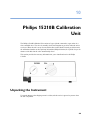
10 Philips 15210B Calibration Unit
325
Unpacking the Instrument
325
Initial Inspection
326
Instrument Identification
326
Specification
326
Operating Environment
327
Operating Information
327
Fitting the Gas Cylinders
327
Storage of Gas Cylinders
327
Disposal of Used Gas Cylinders
Routine Maintenance
Changing the Gas Cylinders
327
327
327
Care and Cleaning
328
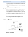
Theory of Operation
328
Gas Flow Performance Check
329
Test Procedure
329
Disassembly
331
Parts List
332
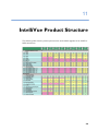
11 IntelliVue Product Structure
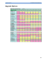
Upgrade Options
12 Index
8
335
337
341
1
Introduction
1
This Service Guide contains technical details for the IntelliVue MP80/90 Patient Monitor, the
Multi-Measurement Module (MMS), the IntelliVue X2, the Flexible Module Rack (FMS) and
the Measurement Server Extensions.
This guide provides a technical foundation to support effective troubleshooting and repair. It is
not a comprehensive, in-depth explanation of the product architecture or technical
implementation. It offers enough information on the functions and operations of the monitoring
systems so that engineers who repair them are better able to understand how they work.
It covers the physiological measurements that the products provide, the Measurement Server that
acquires those measurements, and the monitoring system that displays them.
Who Should Use This Guide
This guide is for biomedical engineers or technicians responsible for troubleshooting, repairing,
and maintaining Philips’ patient monitoring systems.
How to Use This Guide
This guide is divided into eight sections. Navigate through the table of contents at the left of the
screen to select the desired topic. Links to other relevant sections are also provided within the
individual topics. In addition, scrolling through the topics with the page up and page down keys
is also possible.
Abbreviations
Abbreviations used throughout this guide are:
Name
Abbreviation
IntelliVue MP80/90 Patient Monitor
the monitor
Flexible Module Rack
FMS
9
1 Introduction
Responsibility of the Manufacturer
Name
Abbreviation
Multi-Measurement Module
MMS
Measurement Link
MSL
Medical Information Bus
MIB
Anesthetic Gas Module
AGM
Responsibility of the Manufacturer
Philips only considers itself responsible for any effects on safety, EMC, reliability and
performance of the equipment if:
-
assembly operations, extensions, re-adjustments, modifications or repairs are carried out by
persons authorized by Philips, and
-
the electrical installation of the relevant room complies with national standards, and
-
the instrument is used in accordance with the instructions for use.
To ensure safety and EMC, use only those Philips parts and accessories specified for use with
the monitor. If non-Philips parts are used, Philips is not liable for any damage that these parts
may cause to the equipment.
This document contains proprietary information which is protected by copyright. All Rights
Reserved. Reproduction, adaptation, or translation without prior written permission is prohibited,
except as allowed under the copyright laws.
Philips Medizin Systeme Böblingen GmbH
Hewlett-Packard Str. 2
71034 Böblingen, Germany
The information contained in this document is subject to change without notice.
Philips makes no warranty of any kind with regard to this material, including, but not limited to,
the implied warranties or merchantability and fitness for a particular purpose.
Philips shall not be liable for errors contained herein or for incidental or consequential damages
in connection with the furnishing, performance, or use of this material.
10
Passwords
1 Introduction
Passwords
In order to access different modes within the monitor a password may be required. The
passwords are listed below.
Monitoring Mode: No password required
Configuration Mode: 71034
Demo Mode: 14432
Service Mode: 1345
Consult the configuration guide before making any changes to the monitor configuration.
Warnings and Cautions
In this guide:
-
A warning alerts you to a potential serious outcome, adverse event or safety hazard. Failure
to observe a warning may result in death or serious injury to the user or patient.
-
A caution alerts you where special care is necessary for the safe and effective use of the
product. Failure to observe a caution may result in minor or moderate personal injury or
damage to the product or other property, and possibly in a remote risk of more serious
injury.
11
1 Introduction
12
Warnings and Cautions
2
Theory of Operation
2
Monitor Theory of Operation
The IntelliVue MP80/MP90 Patient Monitor:
-
displays real-time data
-
controls the attached measurement servers
-
alarms in the case of patient or equipment problems
-
offers limited data storage and retrieval (trending)
-
interfaces to the Philips Clinical Network and other equipment
A monitor with just a single integrated measurement server can be connected to additional
building blocks to form a monitoring system with a large number of measurements, additional
interface capabilities and multiple slave displays. These elements cooperate as one single
integrated real-time measurement system.
13
2 Theory of Operation
Monitor Theory of Operation
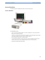
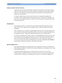
System Boundaries
The following diagram discusses specific boundaries within the overall system with respect to
their openness and real-time requirements:
Measurement LAN
combines components of one patient monitor; real time requirements
across all interconnected elements
Philips Clinical Network (wired LAN)
connects multiple patient monitors, information centers, application
servers; closed system, only Philips qualified products (tested and
with regulatory approval) are connected, Philips is responsible for
guaranteed real-time functionality and performance
Philips Clinical Network (wireless)
like Philips Clinical Network (wired) LAN, however due to current
wireless technologies available it has reduced bandwidth, longer
latencies, reduced functionality
Hospital LAN, Internet
Standard Network, not under Philips control, no guaranteed service,
no real-time requirements
14
Monitor Theory of Operation
2 Theory of Operation
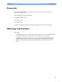
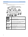
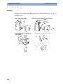
Hardware Building Blocks
The following hardware building blocks make up the monitoring system:
IntelliVue MP80/MP90
The MP80/MP90 monitor:
-
can be used with the standalone M8031A 15-inch or the M8033A 17-inch color LCD TFT
display with touchscreen operation.
-
can also be used with other XGA and SXGA standalone off-the-shelf displays which comply
with medical standards such as IEC 60601-1 and IEC 60601-1-2.
-
has the central processing unit in a separate module
-
uses the Philips SpeedPoint as primary input device whereas the Philips Touchscreen and
computer devices such as mice, trackball, and keyboard can be added optionally
-
supports the Flexible Module Rack (FMS)
15
2 Theory of Operation
Monitor Theory of Operation
Building Blocks:
Optional Hardware
The M8031A 15-inch color LCD TFT display or the M8033A 17-inch color LCD TFT display
(both with touchscreen operation) can be ordered optionally. Additional input devices such as
mice, trackball or keyboard can also be added. If the monitor is ordered with the wireless LAN
option a wireless transmitter is required. For further details regarding the wireless network please
refer to the M3185A Philips Clinical Network documentation.
16
Monitor Theory of Operation
2 Theory of Operation
Compatible Devices
M3001A Multi-Measurement Module (MMS)
M3002A IntelliVue X2
M3012A, M3014A, M3015A, M3016A MMS Extensions
17
2 Theory of Operation
Monitor Theory of Operation
Power Supply
The AC/DC converter transforms the AC power coming from the power plug into 48 V/120W
DC source and isolates the monitoring system from the AC power mains.The 48V is distributed
via power bus and supplies power to all the components of the system: The 56 V DC power
needed for the FMS, MMS and MMS Extension is created by an isolating DC/DC converter.
The CPU is supplied with 3.3 V and 5 V DC power. The transformation is performed in two
steps: The first DC/DC converter is a power regulator which reduces the variations caused by
load changes on the 48V power bus. The second DC/DC converter converts the power to the
needed voltage. Interface boards require a power of 10V AC.
CPU Boards
The CPU boards have an MPC860 50 MHz or MPC86x 100 MHz processor that provides a
number of on-chip, configurable interfaces. An array of 12 fast UARTS with configurable
protocol options are implemented in an ASIC (along with other system functions such as
independent watchdogs etc.), providing interfacing capabilities to measurement modules and I/O
boards. The serial interfaces can easily be electrically isolated. The main board contains
additional video hardware.
The CPUs provide two LAN interfaces to interconnect CPUs (via the MSL) and to connect to the
Philips Clinical Network.
The CPU capabilities are identical. Different loading options are coded on serial EEPROMs to
support the automatic configuration of the operating system at boot time.
18
Monitor Theory of Operation
2 Theory of Operation
I/O Boards
Interfaces to the monitor are implemented via I/O boards. The location of these boards is
restricted by general rules. The I/O slot designations diagram and the I/O matrix which outline
the I/O board placement rules can be found in the Installation Instructions section.
The following is a list of Interface (I/O) boards which may be present in your monitor,
depending on your purchased configuration:
-
MSL
-
Video (analog)
-
Philips Clinical Network (LAN wired or wireless)
-
Basic Alarm Relay (Nurse Call)
I/O boards:
-
PS/2
-
MIB/RS232
-
USB
-
Flexible Nurse Call
-
Parallel printer
-
Remote devices (Remote Alarm Device, Remote Extension Device)
-
IntelliVue 802.11 Bedside Adapter
The specifications for the above listed interfaces can be found in the technical data sheet for the
monitor and in the Installation and Specifications chapter of the Instructions for Use.
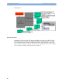
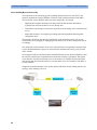
Data Flow
The following diagram shows how data is passed through the monitoring system. The individual
stages of data flow are explained below.
19
2 Theory of Operation
Monitor Theory of Operation
Data Acquisition
Monitoring data (for example patient measurement data in the form of waves, numerics and
alerts) is acquired from a variety of sources:
-
Measurement Servers
The Measurement Servers connected to the internal LAN convert patient signals to digital
data and apply measurement algorithms to analyze the signals.
-
External measurement devices
Data can be also acquired from devices connected to interface boards of the monitor.
Software modules dedicated to such specific devices convert the data received from an
external device to the format used internally. This applies to parameter modules and the
Anesthetic Gas Module.
-
Server systems on the Philips Clinical Network
To enable networked applications such as the other bed overview, data can be acquired from
server systems attached to the Philips Clinical Network, for example a Philips Information
Center
Data Provider System Service
All data that is acquired from measurement servers or external measurement devices is
temporarily stored by a dedicated data provider system service. All monitor applications use this
central service to access the data in a consistent and synchronized way rather than talking to the
interfaces directly.
This service makes the applications independent of the actual type of data acquisition device.
The amount of data stored in the data provider system service varies for the different data types.
For example several seconds of wave forms and the full set of current numerical values are
temorarily stored in RAM.
Persistent Data Storage System Service
Some applications require storage of data over longer periods of time. They can use the
persistent data storage system service. Dependent on the application requirements, this service
can store data either in battery backed-up (buffered) memory or in flash memory. The buffered
memory will lose its contents if the monitor is without power (not connected to mains) for an
extended period of time. The flash memory does not lose its contents.
The trend application for example stores vital signs data in a combination of flash memory and
buffered memory, while the system configuration information (profiles) is kept purely in flash
memory.
20
Monitor Theory of Operation
2 Theory of Operation
Display and User Interface Service
Applications can use high level commands to display monitoring data or status and command
windows on the internal LCD panel. These commands are interpreted by the display manager
application. This application controls the dedicated video hardware which includes video
memory and a special ASIC.
User input is acquired from a variety of input devices, for example the SpeedPoint, the
touchscreen or other standard input devices (keyboard, mouse) which may be attached to I/O
boards. The system software makes sure that the user input is directed to the application which
has the operating focus.
Data Output
The monitoring system is very flexible and customizable regarding its data output devices.
Built-in devices (for example LAN, alarm lamps, speaker, video) provide the basic output
capabilities.
These capabilities can be enhanced by adding additional I/O boards, as required in the specific
end-user setup. The additional I/O boards typically provide data to externally attached devices,
for example to printers, RS232 based data collection devices, nurse call systems etc.
The monitor can identify I/O boards by means of a serial EEPROM device that stores type and
version information. The operating system detects the I/O boards and automatically connects
them with the associated (interface driver) application. For some multi-purpose cards it is
necessary to configure the card for a particular purpose first (for example the dual MIB/RS232
card can support external touch display , data import, data export).
Monitor Applications
The monitor applications provide additional system functionality over the basic measurement
and monitoring capabilities. This includes for example trending, report generating, event storage
or derived measurements.
In general, the monitor applications use the data provider system service to access the
measurement data. Application interfaces to the other system services allow the application to
visualize data, to store data over extended periods of time or to output data to other devices.
21
2 Theory of Operation
Monitor Theory of Operation
Internal LAN (Measurement Link)
All components of the monitoring system (including measurement servers and CPUs in the
monitor) communicate using an IEEE802.3/ Ethernet LAN in the Measurement Link (MSL).
This network is used to distribute data between the components, for example:
-
Digitized patient signals including wave data, numerical data and status information
(typically from the measurement server to a display unit)
-
Control data representing user interactions (typically from the display unit to a measurement
server)
-
Shared data structures, for example representing patient demographical data and global
configuration items
The internal LAN allows plug and play configuration of the monitoring system. The system
automatically detects plugging or unplugging of measurement servers and configures the system
accordingly.
The components on the internal LAN are time-synchronized to keep signal data consistent in the
system. Dedicated hardware support for synchronization eliminates any latency of the network
driver software.
The integrated LAN provides deterministic bandwidth allocation/reservation mechanisms so that
the real-time characteristic of signal data and control data exchange is guaranteed. This applies
to the data flow from the measurement server to the monitor (for example measurement signal
data) and the data flow from the monitor to a measurement server (for example to feed data to a
recorder module).
Integrated communication hubs in the monitor and the FMS allow flexible cabling options (star
topology, daisy chaining of servers).
22
Monitor Theory of Operation
2 Theory of Operation
Philips Clinical Network
The monitoring system may be connected to the Philips Clinical Network, for example to
provide central monitoring capabilities or other network services. This connection may be
through a normal wired connection or through a wireless connection.
The monitor supports the connection of an external wireless adapter or an internal wireless
adapter (#J35). Switching between wired and wireless networks is automatically triggered by the
plugging or unplugging of the network cable.
The Philips Clinical Network protocols function very similarly to the protocols used on the
internal LAN.
After configuration, the monitoring system sends the digitized patient signals including wave
data, numerical data and status information onto the network. Control data representing user
interactions can be exchanged between the monitoring system and a central station
bi-directionally.
Additional protocols are supported for networked applications, for example for the other bed
overview function, which allows viewing of monitoring data from other patients on the network.
For plug and play operation, the monitoring system uses the standard BootP protocol to
automatically acquire a network address.
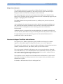
How does the Support Tool Work with the Monitor
The support tool is a Windows application typically installed on the laptop of a customer
engineer or a biomedical engineer working in the customer’s own service department.
The purpose of the support tool is to upgrade, configure and diagnose all monitoring components
(modules, measurement servers, and monitors) in the system over the network.
The service protocol developed for this purpose uses a raw access to the devices without the
need for IP addresses etc. over a standard customer network installation, so that even defective
devices can be upgraded as long as the few kBytes of initial boot code are working. The boot
code itself can also be upgraded using the same protocol.
The tool allows access to internal service information and to serial numbers. It can be remotecontrolled, for example via a dial-up connection from a response center, provided the proper
infrastructure is in place.
For details see the Instructions for Use for the Support Tool.
23
2 Theory of Operation
Monitor Theory of Operation
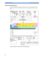
Monitor Software Block Diagram
shows the functional block diagram for the monitoring system. A legend explaining terms and
diagram elements follows. The information below varies depending on the purchased monitor
options.
IntelliVue Patient Monitoring System Functional Block Diagram
24
Monitor Theory of Operation
2 Theory of Operation
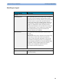
Block Diagram Legend
Functional Block
Description
Services
Operating System
The Operating System (OS) provides a layer of isolation
between the specific hardware implementation and the
application software. The OS performs system checks and
allocates resources to ensure safe operation when the
system is first started. This includes internal self-tests on
several hardware modules and configuration checks for
validity of configuration with the operating software.
During normal operation, the OS continues to run checks
on system integrity. If error conditions are detected the
OS will halt monitoring operations and inform the
operator about the error condition.
System Services
The System Services provide generic common system
services.
In particular:
They use a real-time clock component to track time. They
synchronize to network time sources and verify the
accuracy of the system time information. They are also
responsible for managing persistent user configuration
data for all Measurement Servers, Flexible Module Racks
and IntelliVue Patient Monitoring System software
modules. User configuration data is stored in a
non-volatile read/write storage device
Applications
Application Server Client
The Application Server Client provides the Citrix1
client functionality.
thin
25
2 Theory of Operation
Monitor Theory of Operation
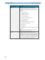
Functional Block
Description
Reports
The Reports Service retrieves current and stored
physiological data and status data to format reports for
printing paper documentation. The following reports are
supported:
-
Vital Signs Report
-
Graphical Trend Report
-
Event Review Report
-
Event Episode Report
-
ECG Report (12 Lead/Multi-Lead)
-
Cardiac Output Report
-
Calculations Report
(Hemodynamic/Oxygenation/Ventilation)
-
Calculations Review Report
-
Wedge Report
-
Test Report
-
Other reports (e.g. Loops, Review Applications, Drug
report)
The Reports service generates report data which can be
printed on a local or a central printer.
Record
26
The Record Service retrieves current and stored
physiological data and status data to format a continuous
strip recording. A recording can be triggered manually by
the operator or automatically by an alarm condition. The
Record Service uses the services of the Recorder Interface
to control an M1116B Recorder in the FMS. The Record
Service can also send data to a central recorder.
Monitor Theory of Operation
2 Theory of Operation
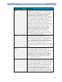
Functional Block
Description
Alarm
The Alarm Service contains logic that prioritizes alarm
conditions that are generated either by the Measurement
Servers, Flexible Module Rack, or by IntelliVue Patient
Monitoring System software modules. Visual alarm
signals (messages) are displayed at the top of the
IntelliVue Patient Monitoring System display and alarm
sounds are generated by a loudspeaker. Alarm conditions
may be generated when a physiological parameter
exceeds preselected alarm limits or when a physiological
parameter or any other software module reports an
inoperative status (technical alarm, for example, the ECG
leads may have fallen off the patient). The Alarm service
manages the alarm inactivation states, for example
suspension of alarms, silencing of alarms, and alarm
reminder. Alarm signals may also be configured as
latching (alarm signals are issued until they are
acknowledged by the operator, even when the alarm
condition is no longer true). The Alarm service controls
the visual alarm signals (alarm lamps).
Trend
The Trend service stores the sample values of
physiological data and status data with a resolution of 12
seconds, 1 minute or 5 minutes for a period of up to 48
hours. The data is kept in battery buffered read/write
storage and flash memory devices to be preserved across
power failures. The stored data is protected via
consistency checks and checksums. When a new patient is
admitted, the trend database erases all data of the previous
patient.
HiRes
The OxyCRG (Oxygen CardioRespiroGram) service
derives a high-resolution trend graph from the
Beat-to-Beat Heart Rate, SpO2 or tcpO2, and Respiration
physiological data. The OxyCRG is specialized for
neonatal applications, allowing the operator to identify
sudden drops in Heart Rate (Bradycardia) and SpO2 or
tcpO2 (Desaturations), and supporting the operator in
visualizing Apnea situations.
ADT
The ADT (Admit/Discharge/Transmit) service maintains
the patient demographics information. The operator may
admit a new patient, discharge the old patient and enter or
modify the patient demographics. The ADT service also
supports the transport of a patient (trend database) with
the M3001A Multi-Measurement Module. The ADT
service controls the deletion of old patient data, the
upload of trend data from the M3001A and the switching
back of all settings to user defaults. It also synchronizes
patient information with a central station on the network.
27
2 Theory of Operation
Monitor Theory of Operation
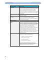
Functional Block
Description
Calc Param
The Calc Param (Calculated Parameters) service accesses
current, stored and manually entered physiological data as
input to calculation formulas. With these formulas,
derived hemodynamic, oxygenation and ventilation
variables are computed. The calculation results, including
the input parameters, are stored for later review using the
Trend service.
Drug Calc
The Drug Calc application aids in calculating drug
dosages for patients.
PV Loops
The PV Loops application compares graphic
representations of airway waves to help detect changes in
the patient airway condition.
Interface Managers
MDSE
The MDSE (Medical Data Service Element) Interface
Manager is responsible for the exchange of real-time data
between the IntelliVue Patient Monitoring System display
unit and the Measurement Servers and Flexible Module
Rack as well as between the IntelliVue Patient
Monitoring System display unit and other devices
attached to the network. MDSE establishes and maintains
a data communication link between the devices. It
provides configuration information about the remote
device to applications in the local device and it allows the
exchange of measurement data and status information
between the devices.
Printer
The Printer Interface Manager provides a high level
interface to a printer. It provides means to:
-
establish a connection to the printer
-
transfer data to the printer
-
get status of the printer
-
close connection to the printer
The Printer Interface Manager also supervises the
connection to the printer and whether the printer accepts
data (for example paper out). The Printer Interface
Manager notifies the operator in such cases.
28
Monitor Theory of Operation
2 Theory of Operation
Functional Block
Description
Display & Operator
Interface
The Display and Operator Interface Manager performs the
following tasks:
-
Screen presentation of real-time and stored
physiological measurement data, alarm condition data
and status information received from the MDSE
interface manager, the Alarm service or other
IntelliVue Patient Monitoring System modules
-
Screen presentation of operating controls (control
windows)
-
Processing of operating control commands received
from HIF Control interface. The module verifies and
interprets the received commands and forwards them
to other software modules of the IntelliVue Patient
Monitoring System display unit, Measurement
Servers or Flexible Module Rack
-
Sound generation (issues audible alarm signals and
generates audible information signals, for example
QRS and SpO2 tones, operator audible feedback)
Interfaces
LAN
The LAN interface implements the physical layer of IEEE
802.3. The LAN interface performs Manchester
encoding/decoding, receive clock recovery, transmit pulse
shaping, jabber, link integrity testing, reverse polarity
detection/correction, electrical isolation, and ESD
protection. Electronically separated interfaces are used for
communication to the Measurement Servers or Flexible
Module Rack and to the network.
Centronics
The Centronics interface implements the standard
signaling method for bi-directional parallel peripheral
devices according to IEEE 1284-I. The interface is used
as a parallel interface to a standard printer with electrical
isolation and ESD protection.
29
2 Theory of Operation
30
Monitor Theory of Operation
Functional Block
Description
Display Controller
The Display Controller Interface consists of a video
controller chip, video RAM and the controlling software.
The Display Controller interface processes the high level
display commands (character and graphic generation,
wave drawing) and translates them into pixels, which are
written into the video RAM where the video controller
chip generates the video synchronization signals and the
pixel stream for the Color LCD Display.
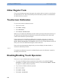
HIF Control
The HIF (Human Interface Control) interface scans the
Human Interface devices for operator controls (Touch
Screen, Speed Point, USB and PS/2 devices), formats the
collected data and sends it to the display and Operating
Interface.
ECG-Out Marker-In
The ECG Out/Marker In interface receives the ECG
waveform directly from the ECG/Resp Arrhythmia
ST-Segment physiological algorithm via an RS-422 serial
interface and converts the digital ECG signal to an analog
ECG signal. In addition, the ECG Out controller receives
from a connected device the marker information and
forwards this data to the ECG/Resp Arrhythmia
ST-Segment physiological algorithm. The converted
analog signal is used to synchronize a connected device to
the patient’s ECG
RS-422
The serial link RS-422 interface communicates the ECG
signal to the ECG Output/Marker In of the IntelliVue
Patient Monitoring System display unit. The interface is a
serial, differential, full-duplex link. The interface is ESD
protected.
PS/2
The PS/2 interface supports the serial protocol of standard
PS/2 devices (mouse). The PS/2 serial protocol is
interpreted by the HIF Control interface.
Nurse Call
The Nurse Call board contains 2 connectors. A phone
jack type connector and a multi-port connector. The
phone jack type connector has a single close-on-alarm
relay. The multi-port connector has three alarm relays
which are configurable to be open or closed on alarm. In
addition, this interface has an audible alert capability for
loss of AC power.
MIB
The MIB interface allows full-duplex, short-haul
asynchronous binary communication between the monitor
and an arbitrary (medical/non-medical) device using an
eight-pin RJ45 modular connector. Switching between
MIB and RS232 protocol is possible.
Monitor Theory of Operation
2 Theory of Operation
Functional Block
Description
USB Interface
The USB interface allows connection of USB devices
(Mouse, Keyboard, Barcode Scanner, Printer) to the
monitor.
31
2 Theory of Operation
32
Monitor Theory of Operation
3
Testing and Maintenance
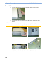
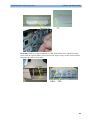
3
Introduction
This chapter provides a checklist of the testing and maintenance procedures to ensure the
performance and safety of the monitor, the Multi-Measurement Module (MMS),the MMS
Extensions and the Flexible Module Rack (FMS) associated modules.
These tests must be performed only by qualified personnel certified by the responsible
organization. Qualifications required are: training on the subject, knowledge, experience and
acquaintance with the relevant technologies, standards and local regulations. The personnel
assessing safety must be able to recognize possible consequences and risks arising from
non-conforming equipment.
All recurring safety and performance assurance tests must be performed under equal
environmental conditions to be comparable.
Preventive Maintenance refers specifically to the series of tests required to make sure the
measurement results are accurate. The accuracy and performance procedures are designed to be
completed as specified in the following sections or when readings are in question.
For detailed instructions on the maintenance and cleaning of the monitor and its accessories, see
Care and Cleaning, Using Batteries and Maintenance and Troubleshooting in the monitor's
Instructions for Use.
33
3 Testing and Maintenance
Terminology and Definitions
Terminology and Definitions
The following terms and definitions are used throughout this chapter and taken from the
international standards IEC 60601-1, IEC 60601-1-1 and IEC 62353.
34
-
Medical System: a medical electrical system is a combination of at least one medical
electrical device and other electrical equipment, interconnected by functional connection or
use of a multiple portable socket-outlet.
-
Patient Vicinity: any area in which intentional or unintentional contact can occur between
the patient and parts of the medical system or between the patient and other persons who
have had contact with parts of the medical system. The patient vicinity is defined anywhere
within 1.5m (5 feet) of the perimeter of the patient's bed and 2.5m (8.2 feet) from the floor.
-
Separation Device/Transformer: a component or arrangement of components with input
parts and output parts that, for safety reasons, prevent a transfer of unwanted voltage or
current between parts of a medical system.
-
Multiple Portable Socket-Outlet: a combination of two or more socket-outlets intended to
be connected to or integrated with flexible cables or cords, which can easily be moved from
one place to another while connected to the power mains.
-
Functional Connection: an electrical connection for transfer of signals and/or power.
-
Tests: Safety or Performance Assurance test procedures which may consist of several steps.
Recommended Frequency
3 Testing and Maintenance
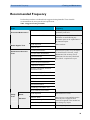
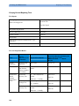
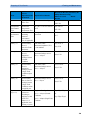
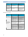
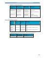
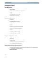
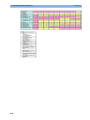
Recommended Frequency
Perform the procedures as indicated in the suggested testing timetable. These timetable
recommendations do not supersede local requirements.
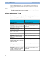
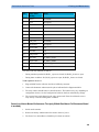
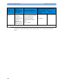
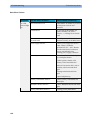
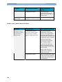
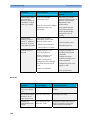
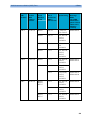
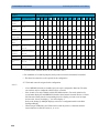
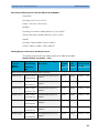
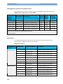
Table 1: Suggested Testing Timetable
Tests
Frequency
Preventive Maintenance*
Other Regular Tests
NBP Performance
Once every two years, or more often if
specified by local laws.
Microstream CO2 Calibration
Once a year or after 4000 hours of
continuous use and following any
instrument repairs or the replacement of
any instrument parts.
Visual Inspection
Before each use.
Power On Test
Performance Assurance
Tests
ECG/Resp Performance
ECG Sync Pulse Performance
SpO2 Performance
NBP Performance
Once every two years, or if you suspect
the measurement is incorrect, except
Mainstream CO2 Accuracy Check,
Sidestream CO2 Accuracy Check and
Flow Check - required once a year.
Invasive Pressure Performance
Temperature Accuracy
M3014A Capnography Extension
Performance Tests
Microstream CO2 Performance Test
Spirometry Accuracy Test
C.O. Performance
BIS Performance
VueLink Performance
IntelliBridge Performance Test
Nurse Call Relay Performance
Safety
Tests
Visual
Electrical
Visual Inspection
After each service event
Protective Earth
Patient Leakage Current
Once every two years and after repairs
where the power supply has been
removed or replaced or the monitor has
been damaged by impact.
System Test
Once every two years
Equipment Leakage Current
35
3 Testing and Maintenance
When to Perform Tests
*M3015A with the old hardware Rev. A (i.e. Serial No. DE020xxxxx) also require the CO2
pump/CO2 scrubber replacement procedure. This is required every three years or after 15000
operating hours.
NOTE
The EEG, SvO2 and tcGas parameters do not require performance testing. See EEG, SvO2
and tcGas Performance Tests (on page 103) for details.
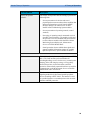
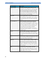
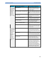
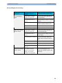
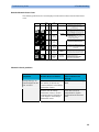
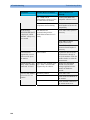
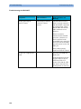
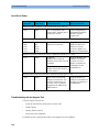
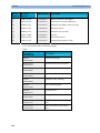
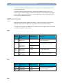
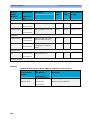
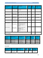
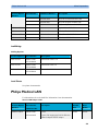
When to Perform Tests
This table tells you when to perform specific tests.The corresponding test procedures are
described in the following sections All tests listed below must be performed on the monitor
itself, any attached MMS/X2 and FMS incl. parameter modules.
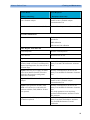
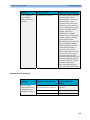
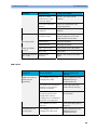
When to perform tests
Service Event
Tests Required
(When performing...
...Complete these tests)
Installation
36
Installation of a monitor in combination with
a medical or non-medical device connected to
the same multiple socket outlet.
Perform Visual Inspection, Power On and
System Tests
Installation of a monitor with no display
connected to the video output
Perform Visual Inspection and Power On Test
Installation of a monitor with a medical
display specified by Philips
Perform Visual Inspection and Power On Test
Installation of a monitor with an off-the-shelf
display (non-compliant with IEC 60601-1)
Perform Visual Inspection, Power On and
System Test
Installation of a monitor with AGM or
IntelliVue G1/G5, connected to separate
mains sockets.
Perform Visual Inspection and Power On Tests
Installation of a monitor with a Vuelink
connection to another medical device
(compliant with IEC 60601-1), connected to
separate mains sockets.
Perform Visual Inspection and Power On Tests
Installation of a monitor with an
IntelliBridge connection to another medical
device (compliant with IEC 60601-1),
connected to separate mains sockets.
Perform Visual Inspection and Power On Tests
Installation of a monitor with IT equipment
e.g. printer, PC connected via a functional
connection e.g. Centronics or USB.
Perform Visual Inspection, Power On and
System Tests
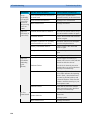
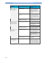
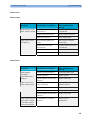
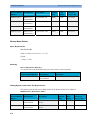
When to Perform Tests
3 Testing and Maintenance
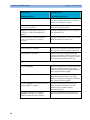
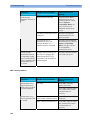
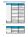
Service Event
Tests Required
(When performing...
...Complete these tests)
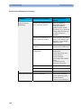
Installation of monitor with IntelliVue
802.11 Bedside Adapter
Perform Visual Inspection, Power On and
IntelliVue 802.11 Bedside Adapter
Communication Test
Installation of networked monitor (LAN)
Perform Visual Inspection and Power On Test
Preventive Maintenance
Preventive Maintenance*
Perform preventive maintenance tests and
procedures:
NBP calibration
Microstream CO2 calibration
Other Regular Tests and Tasks
Visual Inspection
Perform Visual Inspection
Power On Test
Perform Power On test
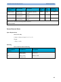
Repairs
Repairs where the monitor, FMS, parameter
modules, MMS or X2 have been damaged by
impact, liquid ingression, fire, short circuit or
electrical surge.
Perform Visual Inspection, Power On, all
Safety Tests and Full Performance Assurance
Tests
Repairs where the power supply, the mains
socket or an interface board is removed or
replaced or the protective earth ground
connection is disrupted.
Perform Visual Inspection, Power On, all
Safety Tests and Basic Performance Assurance
Test
Repairs of IntelliVue 802.11 Bedside
Adapter
Perform Visual Inspection, Power On and
IntelliVue 802.11 Bedside Adapter
Communication Test
Repairs of the parameter modules, FMS,
MMS or X2 (all service events where the
parameter modules, FMS, MMS or X2 have
been opened)
Perform Visual Inspection, Power On, all
Safety Tests and Basic Performance Assurance
Test.
If a certain parameter seems suspicious,
perform Full Performance Assurance Test for
this parameter.
Repairs where the NBP pump of the MMS or
X2 has been replaced
Perform Visual Inspection, Power On, all
Safety Tests, Basic Performance Assurance
Test and NBP Performance Test and
Calibration
37
3 Testing and Maintenance
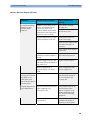
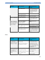
When to Perform Tests
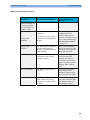
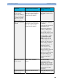
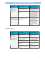
Service Event
Tests Required
(When performing...
...Complete these tests)
Repairs of the AGM or IntelliVue G1/G5
Perform Basic Performance Assurance Test.
For further testing requirements, see AGM or
IntelliVue G1/G5 Service Guide
Repairs where the parameter module, MMS
or X2 has been replaced.
Perform Visual Inspection, Power On and
Basic Performance Assurance
Repairs where the printer connected via
Centronics or USB I/O board has been
replaced.
Perform Visual Inspection, Power On, System
Test and Printer Test.
All other IntelliVue Monitoring System
repairs (except when power supply is
removed)
Perform Visual Inspection, Power On Test and
Basic Performance Assurance Test
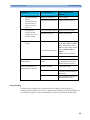
Performance Assurance
Basic Performance Assurance
Perform basic performance assurance tests for
the respective monitoring system component.
Full Performance Assurance
Perform all accuracy and performance test
procedures listed in the following sections. If a
particular measurement is in question, perform
the measurement performance test only.
Upgrades
38
Software Upgrades
Perform Visual Inspection, Power On Test and
Basic Performance Assurance Test unless
otherwise specified in the Upgrade Installation
Notes shipped with the upgrade.
Hardware Upgrades
Perform Visual Inspection, Power On Test and
Basic Performance Assurance Test unless
otherwise specified in the Upgrade Installation
Notes shipped with the upgrade.
Hardware Upgrades where IntelliVue 802.11
Bedside Adapter is installed
Perform Visual Inspection, Power On Test,
Basic Performance Assurance Test and
IntelliVue 802.11 Bedside Adapter
Communication Test
Installation of Interfaces or Hardware
Upgrades where the power supply or
parameter boards need to be removed.
Perform Visual Inspection, Power On Test,
Basic Performance Tests and all Safety Tests
When to Perform Tests
3 Testing and Maintenance
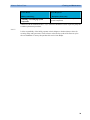
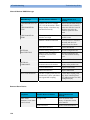
Service Event
Tests Required
(When performing...
...Complete these tests)
Combining or Exchanging System
Components
Perform the System Test for the respective
system components
*M3015A with the old hardware Rev. A (i.e. Serial No. DE020xxxxx) also require the pump and
scrubber replacement procedures.
NOTE
It is the responsibility of the facility operator or their designee to obtain reference values for
recurring safety and system tests. These reference values are the results of the first test cycles
after an installation. You may also purchase this service from Philips.
39
3 Testing and Maintenance
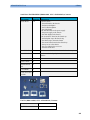
Testing Sequence
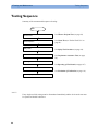
Testing Sequence
Summary of the recommended sequence of testing:
Start
See When to Perform Tests (on page 36)
Select the test
Visual Inspection
Safety Tests
Performance Tests
See Visual Test (see "Before Each Use" on
page 41).
See Safety Test Procedures (on page 44).
See Performance Assurance Tests (on page
84).
Reporting of Results
See Reporting of Test Results (on page 107)
Evaluation of Results
See Evaluation of Test Results (on page 111)
Check and prepare for normal use
NOTE
If any single test fails, testing must be discontinued immediately and the device under test must
be repaired or labeled as defective.
40
Visual Inspection
3 Testing and Maintenance
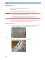
Visual Inspection
Before Each Use
Check all exterior housings for cracks and damage. Check the condition of all external cables,
especially for splits or cracks and signs of twisting. If serious damage is evident, the cable should
be replaced immediately. Check that all mountings are correctly installed and secure. Refer to
the instructions that accompany the relevant mounting solution.
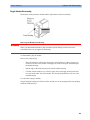
After Each Service, Maintenance or Repair Event
Ensure all fuses accessible from the outside comply with the manufacturer’s specification.
Check:
-
the integrity of mechanical parts, internally and externally.
-
any damage or contamination, internally and externally
-
that no loose parts or foreign bodies remain in the device after servicing or repair.
-
the integrity of all relevant accessories.
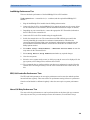
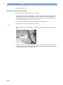
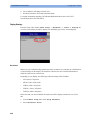
Power On Test
1. Connect the monitoring system to mains and switch it on. This includes connected displays,
MMS, MMS Extensions, X2, FMS and FMS associated modules, gas analyzers and Vuelink
devices.
2. Make sure that all steps listed in the table Initial Instrument Boot Phase in the
Troubleshooting section are completed successfully and that an ECG wave appears on the
screen.
The expected test result is pass: the monitor boots up and displays an ECG wave. The wave
might be a flat line if no simulator is attached.
41
3 Testing and Maintenance
Safety Tests
Safety Tests
Safety tests are comprised of the following tests performed on the monitoring system:
-
protective earth resistance
-
equipment leakage current
-
applied part leakage current
-
system test (if required)
Safety test requirements are set according to international standards, their national deviations and
specific local requirements. The safety tests detailed in this Service Guide are derived from
international standards but may not be sufficient to meet local requirements. We recommend that
you file the results of safety tests. This may help to identify a problem early particularly if the
test results deteriorate over a period of time.
Each individual piece of equipment of the monitoring system which has its own connection to
mains or which can be connected or disconnected from mains without the use of a tool must be
tested individually. The monitoring system as a whole must be tested according to the System
Test (on page 69) procedure.
Accessories of the monitoring system which can affect the safety of the equipment under test or
the results of the safety test must be included in the tests and documented.
42
Safety Tests
3 Testing and Maintenance
Warnings, Cautions, and Safety Precautions
-
These tests are well established procedures of detecting abnormalities that, if undetected,
could result in danger to either the patient or the operator.
-
Disconnect the device under test from the patient before performing safety tests.
-
Disconnect the device under test from mains before performing safety tests. If this is not
possible, ensure that the performance of these tests does not result in danger to the safety
analyzer operator, patients or other individuals.
-
Test equipment (for example, a Safety Analyzer) is required to perform the safety tests.
Please refer to Annex C of IEC/EN 62353 for exact requirements for the measurement
equipment and for measurement circuits for protective earth resistance and leakage currents.
Refer to the documentation that accompanies the test equipment. Only certified technicians
should perform safety testing.
-
The consistent use of a Safety Analyzer as a routine step in closing a repair or upgrade is
emphasized as a mandatory step to maintain user and patient safety. You can also use the
Safety Analyzer as a troubleshooting tool to detect abnormalities of line voltage and
grounding plus total current loads.
-
During safety testing, mains voltage and electrical currents are applied to the device under
test. Ensure that there are no open electrical conductive parts during the performance of
these tests. Avoid that users, patients or other individuals come into contact with touch
voltage.
-
For Europe and Asia/Pacific, the monitor complies with:
IEC60601-1:1988 + A1:1991 + A2:1995 = EN60601-1:1990 +A1:1993 + A2:1995
IEC60601-1-1:2000
For USA, the monitor complies with:
UL60601-1
For Canada, CAN/CSA C22.2#601.1-M90
-
Local regulations supersede the testing requirements listed in this chapter.
-
If a non-medical electrical device is connected to a medical electrical device, the resulting
medical electrical system must comply with IEC/EN 60601-1-1.
-
Perform safety tests as described on the following pages.
43
3 Testing and Maintenance
Safety Tests
Safety Test Procedures
Use the test procedures outlined here only for verifying safe installation or service of the
product. The setups used for these tests and the acceptable ranges of values are derived from
local and international standards but may not be equivalent. These tests are not a substitute for
local safety testing where it is required for an installation or a service event. If using an approved
safety tester, perform the tests in accordance with the information provided by the manufacturer
of the tester and in accordance with your local regulations, for example IEC/EN 60601-1,
UL60601-1 (US), IEC/EN 62353, and IEC/EN 60601-1-1. The safety tester should print results
as detailed in this chapter, together with other data.
Please refer to Annex C of IEC/EN 62353 for requirements for the measurement equipment and
for measurement circuits for protective earth resistance and leakage currents.
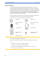
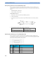
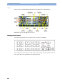
The following symbols are used in the diagrams illustrating the safety tests:
Supply mains
L, N
.........
Supply mains terminals
Protective earth
PE
Protective earth terminal
Mains part
Applied part
F-type applied part
Measuring device
Resistance measuring
device
Connection to accessible
conductive parts
Optional connection
CAUTION
After each service, maintenance or repair event:
Ensure all fuses accessible from the outside comply with the manufacturer’s specification.
Check:
44
-
the integrity of mechanical parts, internally and externally.
-
any damage or contamination, internally and externally.
-
that no loose parts or foreign bodies remain in the device after servicing or repair.
-
the integrity of all relevant accessories.
Safety Tests
3 Testing and Maintenance
Hints for Correct Performance of Safety Tests
-
Perform a visual inspection on all detachable power cords used with the monitoring system
and include these in all safety test procedures.
-
Connection lines such as data lines or functional earth conductors may appear to act like
protective earth connections. These may lead to incorrect measurements and need to be
considered during testing. If necessary, unplug these connections.
-
Position all cables and cords in such a manner that they do not influence the safety tests.
-
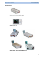
Measurement of insulation resistance is not required.
45
3 Testing and Maintenance
Safety Tests
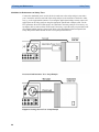
Guideline for Performance of Safety Tests
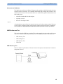
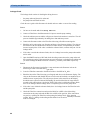
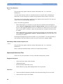
Connect the detachable power cord of the device under test to the safety analyzer's test mains
port. Connect the enclosure test lead of the safety analyzer to the enclosure of the device under
test, e.g. to the equipotential connector. For testing the applied part leakage current, connect all
applied parts to the safety analyzer using the appropriate patient lead or adapter cable. For the
ECG parameter all ten ECG-leads need to be connected to the safety analyzer. If necessary, use
an adapter cable to connect all ten ECG-leads. If necessary, repeat the safety test procedure until
all available applied parts have been tested. Refer to the documentation that accompanies the
safety analyzer for further details on how to set up and perform the test.
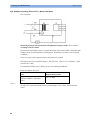
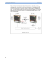
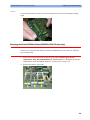
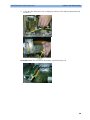
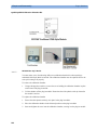
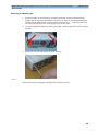
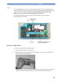
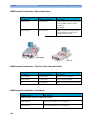
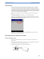
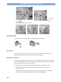
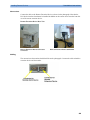
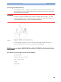
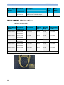
Protective Earth Resistance Test - Setup Example
Equipment Leakage Current Test - Setup Example
46
Safety Tests
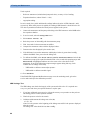
3 Testing and Maintenance
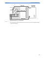
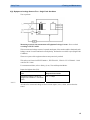
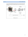
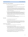
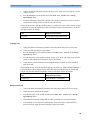
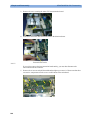
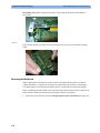
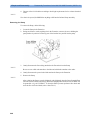
Applied Part Current Test - Setup Example
NOTE
The above graphics resemble the Metron QA-90 setup and are protected by copyright. Copyright
owned by Fluke (Metron).
47
3 Testing and Maintenance
Safety Tests
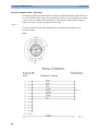
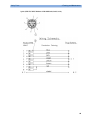
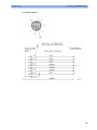
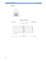
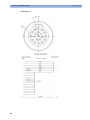
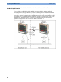
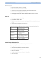
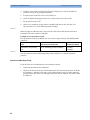
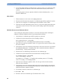
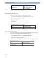
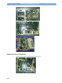
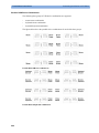
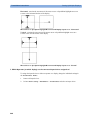
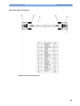
Safety Test Adapter Cable - Schematics
The following graphics provide schematics of safety test (patient lead) adapter cables which can
be used for electrical safety testing. These schematics can also be used as a guideline for making
your own safety test adapter cables. Alternatively, other methods to make safety test adapter
cables can be used, e.g. using a modified accessory cable.
NOTE
You may not need all of the cables displayed below for electrical safety testing of your
respective monitor.
ECG:
48
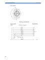
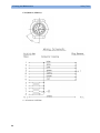
Safety Tests
3 Testing and Maintenance
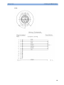
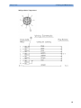
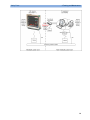
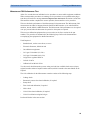
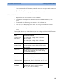
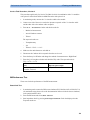
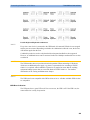
SpO2 (MP2/X2, MP5, M3001A & M1020B #A01, #A02, #A03):
49
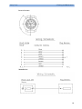
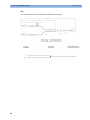
3 Testing and Maintenance
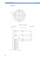
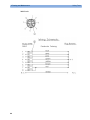
SpO2 (M1020A):
50
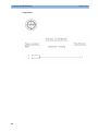
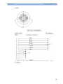
Safety Tests
Safety Tests
3 Testing and Maintenance
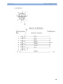
Invasive Pressure:
M1006B #C01:
51
3 Testing and Maintenance
Temperature:
52
Safety Tests
Safety Tests
3 Testing and Maintenance
CO2 (MP5, M3014A):
53
3 Testing and Maintenance
CO2 (M1016A, M3016A):
4 = all resistors 120 KOhm
54
Safety Tests
Safety Tests
3 Testing and Maintenance
Cardiac Output:
55
3 Testing and Maintenance
BIS:
Use Clamp Adapter Cable and M1034-61650 BIS sensor simulator.
56
Safety Tests
Safety Tests
3 Testing and Maintenance
VueLink:
4 = 220 Ohm
57
3 Testing and Maintenance
IntelliBridge:
58
Safety Tests
Safety Tests
3 Testing and Maintenance
EEG:
59
3 Testing and Maintenance
SvO2 (M1021A):
60
Safety Tests
Safety Tests
3 Testing and Maintenance
ScvO2 (M1011A):
61
3 Testing and Maintenance
tcpO2/tcpCO2:
62
Safety Tests
Safety Tests
3 Testing and Maintenance
MP5 predicitive Temperature:
63
3 Testing and Maintenance
MP5 TAAP:
64
Safety Tests
Safety Tests
3 Testing and Maintenance
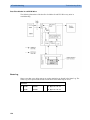
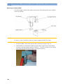
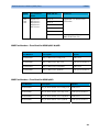
S(1): Protective Earth Resistance Test
Test to perform:
Measuring circuit for the measurement of Protective Earth Resistance in medical electrical
equipment that is disconnected from the supply mains.
This measures the impedance of the Protective Earth (PE) terminal to all exposed metal parts of
the Instrument under Test (IUT), which are for safety reasons connected to the Protective Earth
(PE).
Measurements shall be performed using a measuring device capable to deliver a current of at
least 200 mA into 500 mOhms with maximum 24V
This safety test is based on IEC/EN 60601-1, IEC/EN 62353, UL2601-1 Ed. 2/UL60601-1:2003
and CSA 601.1-M90.
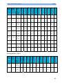
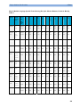
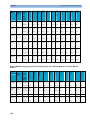
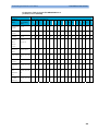
For measurement limits, refer to Safety (1) test, Test and Inspection Matrix.
Report the highest value (X1).
Test
Expected test results
Protective Earth Resistance Test (with
mains cable)
X1 <= 300mOhms
NOTE
-
If the protective earth resistance test fails, testing must be discontinued immediately and the
device under test must be repaired or labeled as defective.
-
All values for current and voltage are the root mean square (r.m.s.) values, unless otherwise
stated.
-
Flex the power cord during the protective earth resistance test to evaluate its integrity. If it
does not pass the test, exchange the power cord.
65
3 Testing and Maintenance
Safety Tests
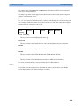
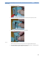
S(2): Equipment Leakage Current Test - Normal Condition
Test to perform:
Measuring circuit for the measurement of Equipment Leakage Current - Direct method
according to IEC/EN 62353.
This test measures leakage current of exposed metal parts of the monitor and the functional earth
leakage current. It tests normal and reversed polarity. Perform the test with S1 closed (Normal
Condition).
There are no parts of the equipment that are not protectively earthed.
This safety test is based on IEC/EN 60601-1, IEC/EN 62353, UL2601-1 Ed. 2/UL60601-1:2003
and CSA 601.1-M90.
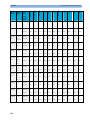
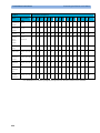
For measurement limits, refer to Safety (2) test, Test and Inspection Matrix.
Report the highest value (X1).
Test
Expected test results
Equipment Leakage Current Test
(Normal Condition - with mains
cable)
X1 <= 100μA
NOTE
All values for current and voltage are the root mean square (r.m.s.) values, unless otherwise
stated.
66
Safety Tests
3 Testing and Maintenance
S(3): Equipment Leakage Current Test - Single Fault Condition
Test to perform:
Measuring circuit for the measurement of Equipment Leakage Current - Direct method
according to IEC/EN 62353.
This test measures leakage current of exposed metal parts of the monitor and the functional earth
leakage current. It tests normal and reversed polarity. Perform the test with S1 open (Single Fault
Condition).
There are no parts of the equipment that are not protectively earthed.
This safety test is based on IEC/EN 60601-1, IEC/EN 62353, UL2601-1 Ed. 2/UL60601-1:2003
and CSA 601.1-M90.
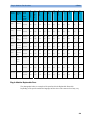
For measurement limits, refer to Safety (3) test, Test and Inspection Matrix.
Report the highest value (X2).
Test
Expected test results
Equipment Leakage Current Test
(Single Fault Condition - with mains
cable)
X2 <= 300μA
NOTE
All values for current and voltage are the root mean square (r.m.s.) values, unless otherwise
stated.
67
3 Testing and Maintenance
Safety Tests
S(4): Applied Part Leakage Current - Mains on Applied Part
NOTE
During measurement of the Applied Part Leakage Current it is possible that the measured current
can exceed the allowed limit (per IEC/EN 60601-1 or IEC/EN 62353).
This can occur when the safety tester is connected to the invasive blood pressure and
temperature connectors at the same time during the applied leakage current measurement.
The connectors for the invasive blood pressure and temperature are independently functioning
connectors.
Although there are individual connectors on the front end, internally those parameters use the
same electrical insulation interface and are hardwired to each other. This results in an electrical
short of those connectors during measurement if a test current is applied simultaneously.
Therefore this should be avoided.
Due to the combined insulation interface, it is sufficient to connect to only one parameter
interface (that is, Invasive Blood Pressure or Temperature) of the invasive blood
pressure/temperature measurement block. This avoids a short and the potential of exceeding the
limit for the current.
Test to perform:
68
Safety Tests
3 Testing and Maintenance
Measuring circuit for the measurement of Applied Part Leakage Current - Direct method
according to IEC/EN 62353.
This test measures applied part leakage current from applied part to earth caused by external
main voltage on the applied part. Each polarity combination possible shall be tested. This test is
applicable for ECG measurement inputs.
There are no parts of the equipment that are not protectively earthed.
This safety test is based on IEC/EN 60601-1, IEC/EN 62353, UL2601-1 Ed. 2/UL60601-1:2003
and CSA 601.1-M90.
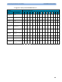
For measurement limits and test voltage, refer to Safety (4) test, Test and Inspection Matrix.
Report the highest value. (X1).
Test
Expected test results
Applied Part Leakage Current Test
(Single Fault Condition - mains on
applied part)
S4 <= 50μA
NOTE
All values for current and voltage are the root mean square (r.m.s.) values, unless otherwise
stated.
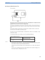
System Test
After mounting and setting up a system, perform system safety tests according to IEC/EN
60601-1-1.
What is a Medical Electrical System?
A medical electrical system is a combination of at least one medical electrical piece of
equipment and other electrical equipment, interconnected by functional connection or use of a
multiple portable socket-outlet.
-
Devices forming a medical electrical system must comply with IEC/EN 60601-1-1.
-
Any electrical device such as IT equipment that is connected to the medical electrical
equipment must comply with IEC/EN 60601-1-1 and be tested accordingly.
69
3 Testing and Maintenance
Safety Tests
General Requirements for a System
After installation or subsequent modification, a system must comply with the requirements of the
system standard IEC/EN 60601-1-1. Compliance is checked by inspection, testing or analysis, as
specified in the IEC/EN 60601-1-1 or in this book.
Medical electrical equipment must comply with the requirements of the general standard IEC/EN
60601-1, its relevant particular standards and specific national deviations. Non-medical electrical
equipment shall comply with IEC safety standards that are relevant to that equipment.
Relevant standards for some non-medical electrical equipment may have limits for equipment
leakage currents higher than required by the standard IEC/EN 60601-1-1. These higher limits are
acceptable only outside the patient environment. It is essential to reduce equipment leakage
currents to values specified in IEC 60601-1 when non-medical electrical equipment is to be used
within the patient environment.
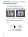
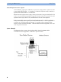
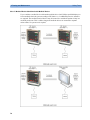
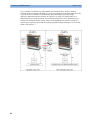
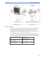
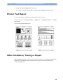
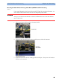
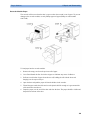
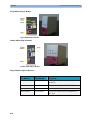
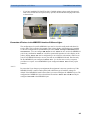
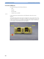
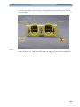
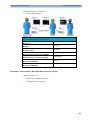
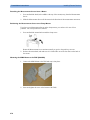
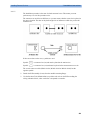
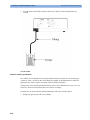
System Example
This illustration shows a system where both the medical electrical equipment and the
non-medical electrical equipment are situated at the patient’s bedside.
70
Safety Tests
3 Testing and Maintenance
WARNING
-
Do not use additional AC mains extension cords or multiple portable socket-outlets. If a
multiple portable socket-outlet is used, the resulting system must be compliant with IEC/EN
60601-1-1. Do not place multiple socket-outlets on the floor. Do not exceed the maximum
permitted load for multiple socket-outlets used with the system. Do not plug additional
multiple socket outlets or extension cords into multiple socket outlets or extension cords
used within the medical electrical system.
-
Do not connect any devices that are not supported as part of a system.
-
Do not use a device in the patient vicinity if it does not comply with IEC/EN 60601-1. The
whole installation, including devices outside of the patient vicinity, must comply with
IEC/EN 60601-1-1. Any non-medical device placed and operated in the patient’s vicinity
must be powered via a separating transformer (compliant with IEC/EN 60601-1-1) that
ensures mechanical fixing of the power cords and covering of any unused power outlets.
71
3 Testing and Maintenance
Safety Tests
System Installation Requirements
72
-
Ensure that the the medical electrical system is installed in a way that the user achieves
optimal use.
-
Make sure the user is informed about the required cleaning, adjustment, sterilization and
disinfection procedures listed in the Instructions for Use.
-
The medical electrical system must be installed in such a way that the user is able to carry
out the necessary cleaning, adjustment, sterilization and disinfection procedures listed in the
Instructions for Use.
-
Ensure that the medical electrical system is installed in a way that an interruption and
restoration of power to any part of the medical electrical system does not result in a safety
hazard.
-
We recommend using fixed mains socket outlets to power the medical system or parts
thereof. Avoid using multiple portable socket-outlets.
-
Any multiple portable socket outlets used must be compliant with IEC 60884-1 and IEC
60601-1-1.
-
Ensure that any part of the system connected to multiple portable socket-outlets is only
removable with a tool, i.e. the multiple portable socket-outlet provides a locking mechanism
to prevent power cords from being plugged or unplugged unintentionally. Otherwise, the
multiple portable socket-outlet must be connected to a separation device. Multiple Socket
Outlets used within the medical electrical system must only be used for powering medical
electrical equipment which is part of the system.
-
Ensure that any functional connections between parts of the medical electrical system are
isolated by a separation device according to IEC 60601-1-1 to limit increased equipment
leakage currents caused by current flow through the signal connections. This only works if
the equipment leakage current of the respective medical electrical system parts is not
exceeded under normal conditions.
-
Avoid increase of equipment leakage currents when non-medical electrical equipment within
the medical electrical system is used. This only works if the equipment leakage current of
the respective medical electrical system parts is not exceeded under normal conditions. Use
additional protective earth connection, separation device or additional non-conductive
enclosures.
-
Within the patient environment it is important to limit electrical potential differences
between different parts of a system. If necessary, use potential equalization equipment
(equipotential cable) or additional protective earth connections.
-
Medical electrical equipment used in medical rooms must be connected to potential
equalization equipment (equipotential cable) to avoid electrical potential differences. Check
your local requirements for details.
Safety Tests
3 Testing and Maintenance
Required Protective Measures at System Installation
For any IT equipment (IEC60950) operated in patient vicinity ensure that the equipment leakage
current does not exceed the limits described in IEC 60601-1. Use a separation device to ensure
compliance. After installation of IT equipment in patient vicinity, an enclosure leakage current
test is required.
73
3 Testing and Maintenance
Safety Tests
Case 1: Medical Device Combined with Medical Device
If you combine a medical device with another medical device (incl. Philips specified displays) to
form a medical electrical system according to IEC60601-1-1, no additional protective measures
are required. The medical electrical devices may be located in or outside the patient vicinity in a
medically used room. This is valid as long as the medical devices are connected to separate
mains outlets. No system test is required.
74
Safety Tests
3 Testing and Maintenance
If the combined medical devices are connected to the same multiple portable socket outlet an
enclosure leakage current test of the entire device combination on the multiple portable socket
outlet is required to ensure that the resulting protective earth leakage current and equipment
leakage current does not exceed the limits of IEC 60601-1-1. Avoid using multiple portable
socket outlets. The medical electrical devices may be located in or outside the patient vicinity in
a medically used room. If the limits are exceeded, additional protective measures are required,
e.g. a separation device or the connection of each device to separate mains.
75
3 Testing and Maintenance
Safety Tests
Case 2: Medical Device Combined with a Non-Medical Device
If you combine a medical device with a non-medical device to form a medical electrical system
according to IEC60601-1-1, additional protective measures are required, e.g. usage of a
separation device. The medical electrical devices or the IT equipment may be located in or
outside the patient vicinity in a medically used room. After system installation incl. protective
measures, a system test is required to ensure that the resulting equipment leakage current and
applied part leakage current does not exceed the limits of IEC 60601-1-1.
76
Safety Tests
3 Testing and Maintenance
For any IT equipment (IEC60950) operated in patient vicinity ensure that the equipment leakage
current does not exceed the limits described in IEC 60601-1. Use a separation device to ensure
compliance. After installation of IT equipment in patient vicinity, an enclosure leakage current
test is required.
77
3 Testing and Maintenance
Safety Tests
If the combined devices forming the medical electrical system are connected to the same
multiple portable socket outlet, ensure that the resulting protective earth leakage current and
equipment leakage current do not exceed the limits of IEC 60601-1-1. The medical electrical
devices or IT equipment may be located in or outside the patient vicinity in a medically used
room. Avoid using multiple portable socket outlets. If the limits of IEC 60601-1-1 are exceeded,
additional protective measures are required, e.g. a separation device or the connection of each
device to separate mains.
78
Safety Tests
3 Testing and Maintenance
For any IT equipment (IEC60950) operated in patient vicinity ensure that the equipment leakage
current does not exceed the limits described in IEC 60601-1. Use a separation device to ensure
compliance. After installation of IT equipment in patient vicinity, an enclosure leakage current
test is required.
79
3 Testing and Maintenance
Safety Tests
Case 3: Medical Device Combined with a Medical or Non-Medical Device with one Device in a
Non-Medically-Used Room
If you combine a medical device with a medical or non-medical device to form a medical
electrical system according to IEC60601-1-1 using a common protective earth connection and
one of the devices is located in a non-medically used room, additional protective measures are
required, e.g. usage of a separation device or additional protective earth connection. The medical
electrical devices or IT equipment may be located in or outside the patient vicinity. After system
installation incl. protective measures, a system test is required to ensure that the resulting
equipment leakage current does not exceed the limits of IEC 60601-1-1.
80
Safety Tests
3 Testing and Maintenance
81
3 Testing and Maintenance
Safety Tests
If you combine a medical device with a medical or non-medical device to form a medical
electrical system according to IEC60601-1-1 using two separate protective earth connections and
one of the devices is located in a non-medically used room creating a potential voltage
difference, additional protective measures are required, e.g. usage of a separation device or
additional protective earth connection. The medical electrical devices or IT equipment may be
located in or outside the patient vicinity. After system installation incl. protective measures, a
system test is required to ensure that the resulting equipment leakage current does not exceed the
limits of IEC 60601-1-1.
82
Safety Tests
3 Testing and Maintenance
System Test Procedure
If the medical electrical device has already been tested as a standalone device e.g. during factory
safety testing, an equipment leakage current test must only be performed once the device is
connected to the LAN network. If the medical electrical system has not been tested as a
standalone device, the device has to be tested as a standalone device (without connection to the
system) and as part of the system (with connection to the system).
Connect the detachable power cord of the device under test to the safety analyzer's test mains
port. Connect the enclosure test lead of the safety analyzer to the enclosure of the device under
test, e.g. to the equipotential connector. Refer to the documentation that accompanies the safety
analyzer for further details on how to set up the test.
Test
Expected test results
Equipment Leakage Current Test
(Normal Condition)
Sys1 <= 100μA
Equipment Leakage Current Test
(Single Fault Condition)
Sys2 <= 300μA
83
3 Testing and Maintenance
Preventive Maintenance Procedures
After the testing of the device as a standalone device and as part of the system, check that the
resulting values (without connection and with connection to the system) do not differ by more
than +/- 10% from each other.
If the devices in the medical electrical system are connected to a multiple portable socket outlet
the resulting protective earth leakage current needs to be determined. All system components
must be connected to the multiple portable socket outlet and be switched on during this
measurement.
Test
Expected test results
Protective Earth Leakage Current of
Multiple Socket Outlets
Sys3 <= 300μA
Refer to the documentation that accompanies the safety analyzer for further details on how to set
up the test.
Preventive Maintenance Procedures
Noninvasive Blood Pressure Measurement Calibration
Carry out the noninvasive blood pressure measurement performance tests at least every two
years , or as specified by local laws (whichever comes first).
Performance Assurance Tests
Some of the following test procedures must be performed in service mode. To enter service
mode select Operating Modes in the main menu. Then select Service Mode and enter the
password.
If required, open the screen menu in the monitor info line at the top of the screen and select
Service to access the service screen. This is required particularly for Anesthetic Gas Module
testing procedures.
Basic Performance Assurance Test
This section describes the basic performance test procedure. Please refer to the section When to
Perform Tests (on page 36) for detailed information on when which test procedure is required.
Procedure:
Power on the monitoring system and go into demo mode. Check that each connected parameter
(integrated, module, MMS, Gas Analyzer, Vuelink connected device) displays values.
84
Performance Assurance Tests
3 Testing and Maintenance
Full Performance Assurance Test
The following sections describe the full performance testing procedures i.e. detailed testing of
each parameter with a patient simulator or specified tools. Please refer to the section When to
perform Tests (on page 36) for information on when which testing procedure is required.
ECG/Resp Performance Test
This test checks the performance of the ECG and respiration measurements.
Tools required: Patient simulator.
ECG Performance
1. Connect the patient simulator to the ECG/Resp connector.
2. Configure the patient simulator as follows:
-
ECG sinus rhythm.
-
HR = 100 bpm or 120 bpm (depending on your patient simulator).
3. Check the displayed ECG wave and HR value against the simulator configuration.
4. The value should be 100bpm or 120 bpm+/- 2 bpm.
Respiration Performance
1. Change the Patient Simulator configuration to:
-
Base impedance line 1500 Ohm.
-
Delta impedance 0.5 Ohm.
-
Respiration rate 40 rpm or 45 rpm.
2. The value should be 40 rpm +/- 2 rpm or 45 rpm +/- 2 rpm.
Test
Expected test results
ECG Performance Test
100bpm +/- 2bpm or
120bpm +/- 2bpm
Respiration Performance Test
40 rpm +/- 2 rpm or
45 rpm +/- 2 rpm
85
3 Testing and Maintenance
Performance Assurance Tests
ECG Sync Performance Test
This test checks the performance of ECG synchronization between the monitor and a
defibrillator. It only needs to be performed when this feature is in use as a protocol at the
customer site.
Tools required:
-
Defibrillator with ECG Sync and Marker Output.
-
Patient simulator.
1. Connect the patient simulator to the ECG connector and the defibrillator to the ECG Sync
Output on the monitor.
2. Set the patient simulator to the following configuration:
-
HR = 100 bpm or 120 bpm (depending on your patient simulator).
-
ECG sinus rhythm.
3. Switch the defibrillator to simulation mode.
4. Check that the marker pulse is displayed before the T-wave begins.
Test
Expected test results
ECG Sync Performance Test
Marker pulse is displayed before
the T-wave begins
SpO2 Performance Test
This test checks the performance of the SpO2 measurement.
Tools required: none
1. Connect an adult SpO2 transducer to the SpO2 connector.
2. Measure the SpO2 value on your finger (this assumes that you are healthy).
3. The value should be between 95% and 100%.
86
Test
Expected test results
SpO2 Performance Test
95% and 100%
Performance Assurance Tests
3 Testing and Maintenance
Measurement Validation
The SpO2 accuracy has been validated in human studies against arterial blood sample reference
measured with a CO-oximeter. In a controlled desaturation study, healthy adult volunteers with
saturation levels between 70% and 100% SaO2 were studied. The population characteristics for
those studies were:
-
about 50% female and 50% male subjects
-
age range: 18 to 45
-
skin tone: from light to black
NOTE
A functional tester cannot be used to assess the accuracy of a pulse oximeter monitor. However,
it can be used to demonstrate that a particular pulse oximeter monitor reproduces a calibration
curve that has been independently demonstrated to fulfill a particular accuracy specification.
NBP PerformanceTest
This section describes NBP test procedures.The monitor must be in service mode and the screen
“Service A” must be selected to perform these tests. The NBP Performance Test consists of:
-
NBP Accuracy Test
-
NBP Leakage Test
-
NBP Linearity Test
-
Valve Test
NBP Accuracy Test
This test checks the performance of the non-invasive blood pressure measurement. Connect the
equipment as shown:
87
3 Testing and Maintenance
Performance Assurance Tests
Tools required:
-
Reference manometer (includes hand pump and valve), accuracy 0.2% of reading.
-
Expansion chamber (volume 250 ml +/- 10%)
-
Appropriate tubing.
In service mode, the systolic and diastolic readings indicate the noise of NBP channels 1 and 2
respectively. When static pressure is applied, the reading in NBP channel 1 should be below 50.
The value in parentheses indicates the actual pressure applied to the system.
1. Connect the manometer and the pump with tubing to the NBP connector on the MMS and to
the expansion chamber.
2. In service mode, select the Setup NBP menu.
3. Select Close Valves: On
4. Raise the pressure to 280 mmHg with the manometer pump.
5. Wait 10 seconds for the measurement to stabilize.
6. Compare the manometer values with the displayed values.
7. Document the value displayed by the monitor (x1).
8. If the difference between the manometer and displayed values is greater than 3 mmHg,
calibrate the MMS. If not, proceed to the leakage test.
9. To calibrate the MMS, select Close Valves off then Calibrate NBP and wait for the
instrument to pump up the expansion chamber.Wait a few seconds after pumping stops until
EnterPrVal is highlighted and then move the cursor to the value shown on the
manometer. If one of the following prompt messages appears during this step, check
whether there is leakage in the setup:
-
NBP unable to calibrate–cannot adjust pressure
-
NBP unable to calibrate–unstable signal
10. Press Confirm.
If the INOP NBP Equipment Malfunction message occurs in monitoring mode, go back to
service mode and repeat the calibration procedure.
NBP Leakage Test
The NBP leakage test checks the integrity of the system and of the valve. It is required once
every two years and when you repair the monitor or replace parts.
1. If you have calibrated, repeat steps 2 to 6 from the accuracy test procedure so that you have
280 mmHg pressure on the expansion chamber.
2. Watch the pressure value for 60 seconds.
3. Calculate and document the leakage test value (x2).
x2 = P1 - P2
where P1 is the pressure at the beginning of the leakage test and P2 is the pressure displayed
after 60 seconds.
The leakage test value should be less than 6 mmHg.
88
Performance Assurance Tests
3 Testing and Maintenance
NBP Linearity Test
1. Reduce the manometer pressure to 150 mmHg.
2. Wait 10 seconds for the measurement to stabilize.
3. After these 10 seconds, compare the manometer value with the displayed value.
4. Document the value displayed by the monitor (x3)
5. If the difference is greater than 3 mmHg, calibrate the MMS (see steps 9 to 10 in the
accuracy test procedure).
Valve Test
1. Raise the pressure again to 280 mmHg.
2. Select Close valves: Off.
3. Wait five seconds and then document the value displayed. The value should be less than 10
mmHg.
4. Document the value displayed by the monitor (x4).
Expected Test Results for NBP Accuracy Test, Leakage Test, Linearity Test & Valve Test
Test
Expected test results
Accuracy test
x1 = value displayed by monitor
Difference ≤ 3mmHg
Leakage test
x2 = leakage test value
x2 < 6 mmHg
Linearity test
x3 = value displayed by monitor
Difference ≤ 3mmHg
Valve Test
x4 = value < 10 mmHg
Invasive Pressure Performance Test
This test checks the performance of the invasive pressure measurement.
Tools required: Patient simulator.
1. Connect the patient simulator to the pressure connector.
2. Set the patient simulator to 0 pressure.
3. Make a zero calibration.
4. Configure the patient simulator as P(static) = 200 mmHg.
5. Wait for the display.
89
3 Testing and Maintenance
Performance Assurance Tests
6. The value should be 200 mmHg ± 5 mmHg. If the value is outside these tolerances, calibrate
the Invasive Pressure measurement. If the measurement was calibrated with a dedicated
reusable catheter, check the calibration together with this catheter.
Table 4:
Test
Expected test results
Invasive Pressure Performance Test
200 mmHg ± 5 mmHg
Temperature Performance Test
This test checks the performance of the temperature measurement.
Tools required: Patient simulator (with 0.1°C or 0.2°F).
1. Connect the patient simulator to the temperature connector.
2. Configure the patient simulator to 40°C or 100°F.
3. The value should be 40°C ± 0.2°C or 100°F ± 0.4°F.
Table 2:
Test
Expected test results
Temperature Performance Test
40°C ± 0.2°C or 100°F ± 0.4°F
M3014A Capnography Extension Performance Tests
The procedures below describe the mainstream and sidestream CO2 performance tests for the
M3014A Capnography Extension.
Mainstream CO2 Accuracy Check
Tools Required:
-
three airway adapters
-
Verification Gas M2506A
-
Gas cylinder regulator M2505A
You also need a local barometric pressure rating received from a reliable local source (airport,
regional weather station or hospital weather station) which is located at the same altitude as the
hospital.
Procedure:
1. Attach the M2501A CO2 sensor to the patient monitor. Attach an airway adapter to the
sensor. Make sure that the sensor is disconnected from the patient circuit.
2. Switch on the patient monitor.
3. Enter the monitor’s Service Mode.
90
Performance Assurance Tests
3 Testing and Maintenance
4. Using the sensor status provided in the M2501A Serial protocol, wait for the M2501A
sensor to warm up to its operating temperature.
5. The default setting for gas temperature is 22°C. If the gas temperature is significantly above
or below this value, correct the gas temperature setting.
6. Zero the sensor on the airway adapter being used in this test. Ensure Zero Gas is set to Room
Air
7. Attach a regulated flowing gas mixture of 5% CO2, balance N2 to the airway adapter.
8. Set the gas correction to off.
9. Allow a few seconds for the gas mixture to stabilize and observe the CO2 value. The
expected value is 5% of the ambient pressure ±2mmHg
NOTE
Make sure that you follow the above steps correctly. If the sensor fails this check it must be
exchanged. The sensor cannot be calibrated.
Example for an expected test result:
The expected test result for an altitude of 0 m (sea level) at approximately 760 mmHg ambient
pressure is:
Table 6:
Test
Expected test results (x1)
Acceptance Range
Mainstream CO2 Accuracy
Test
5% of 760 mmHg pressure ±2mmHg
36 mmHg 40 mmHg
NOTE
The expected test results will differ depending on the conditions (i.e. altitude or ambient
pressure).
Sidestream CO2 Accuracy Check
Tools Required:
-
Cal gas flow regulator M2267A
-
Cal tube 13907A
-
Verification Gas M2506A
-
Straight Sample Line M2776A
You also need a local barometric pressure rating received from a reliable local source (airport,
regional weather station or hospital weather station) which is located at the same altitude as the
hospital.
Procedure:
1. Attach the M2741A CO2 sensor to the patient monitor. Attach the sample line and the cal
tube to the sensor. Make sure that the sensor is disconnected from the patient circuit.
2. Switch on the patient monitor.
3. Enter the monitor’s Service Mode.
91
3 Testing and Maintenance
Performance Assurance Tests
4. Using the sensor status provided in the M2741A Serial protocol, wait for the M2741A
sensor to warm up to its operating temperature.
5. Zero the sensor. Ensure Zero Gas is set to Room Air
6. Attach a regulated flowing gas mixture of 5% CO2, balance N2 to the cal tube.
7. Set the gas correction to off.
8. Allow a few seconds for the gas mixture to stabilize and observe the CO2 value. The
expected value is 5% of the ambient pressure ±2mmHg
NOTE
Make sure that you follow the above steps correctly. If the sensor fails this check it must be
exchanged. The sensor cannot be calibrated
Example for an expected test result:
The expected test result for an altitude of 0 m (sea level) at approximately 760 mmHg ambient
pressure is:
Test
Expected test results (x2)
Acceptance Range
Sidestream CO2 Accuracy
Test
5% of 760 mmHg pressure ±2mmHg
36 mmHg 40 mmHg
NOTE
The expected test results will differ depending on the conditions (i.e. altitude or ambient
pressure).
Sidestream CO2 Flow Check
Check the flow rate in the Sidestream CO2 extension as follows:
1. Connect the flowmeter to the sample line
2. Check on the flowmeter the flow that the Sidestream CO2 extension pump draws. It should
be 50 ml/min ± 10 ml/min. If the value is not within tolerance check your setup again and
perform another flow check. If it fails again, the sensor must be replaced. The sensor cannot
be calibrated.
92
Performance Assurance Tests
3 Testing and Maintenance
Microstream CO2 Performance Test
Allow five seconds between individual service procedures to ensure stable equipment conditions.
When certain monitor procedures are running, service procedures are not possible and trying to
start them will result in a message Service Operation Failed in the monitor’s status line.
Wait until the monitor completes the current operation, then restart the service procedure.
This test checks the performance of the Microstream CO2 measurement. The Microstream CO2
measurement can either be integrated into the IntelliVue MP5 monitor or, for other IntelliVue
monitors, into the M3015A MMS Extension. The Microstream CO2 performance test is required
once per year and when the instrument is repaired or when parts are replaced.
This test uses calibration equipment that you can order (see the Parts section for the part
number). The procedure is summarized in the following steps. Refer to the documentation
accompanying the equipment for detailed instructions.
Tools Required:
-
Standard tools, such as screwdriver, tweezers
-
Electronic flowmeter, M1026-60144
-
Gas calibration equipment:
-
Cal 1 gas 15210-64010 (5% CO2)
-
Cal 2 gas 15210-64020 (10% CO2)
-
Cal gas flow regulator M2267A
-
Cal tube 13907A
-
Calibration Line M3015-47301
You also need a local barometric pressure rating received from a reliable local source (airport,
regional weather station or hospital weather station) which is located at the same altitude as the
hospital.
The CO2 calibration for the Microstream extension consists of the following steps:
-
Leakage check
-
Barometric pressure check and calibration, if required.
-
Pump check
-
Flow check and calibration, if required
-
Noise check
-
CO2 Cal check and calibration, if required
-
CO2 Cal verification using 2nd cal gas
Perform all checks in the same session.
93
3 Testing and Maintenance
Performance Assurance Tests
Leakage Check
The leakage check consists of checking the tubing between:
-
the pump outlet and the mCO2 outlet and
-
the pump inlet and FilterLine inlet.
Check the user’s guide of the flowmeter for details on how to make a correct flow reading.
Part 1
1. Go into service mode and select Setup CO2 menu.
2. Connect a FilterLine to the Microstream CO2 input to start the pump running.
3. Check the ambient pressure and the cell pressure shown in the monitor’s status line. The cell
pressure should be approximately 20 mmHg lower than ambient pressure.
4. Connect the flowmeter outlet to the FilterLine inlet using a flexible connecting tube.
5. Block the mCO2 outlet using your fingertip and observe the flowmeter display. The value on
the flowmeter (x1) should decrease to between 0 and 4 ml/min, accompanied by an audible
increase in pump noise. If the value is within the tolerance limits, continue with part 2 of the
leakage check.
6. If the value is outside the tolerance limits, there is a leakage between the pump outlet and the
mCO2 outlet.
7. Open the MMS Extension or MP5 and check the tubing connections at the pump outlet and
the extension gas outlet. If the connections are good, then there is a leakage in the tubing and
you must exchange the MMS Extension or the mCO2 Assembly of the MP5 respectively.
Part 2
1. Disconnect the flowmeter from the Part 1 setup and connect the flowmeter inlet to the
M3015A gas outlet or the MP5 mCO2 gas outlet.
2. Leave the Filterline connected to the M3015A inlet or the MP5 mCO2 inlet..
3. Block the inlet of the FilterLine using your fingertip and observe the flowmeter display. The
value on the flowmeter (x2) should decrease to between 0 and 4 ml/min, accompanied by an
audible increase in pump noise. The cell pressure shown in the status line on the display
should decrease to between 300 and 500 mmHg. Do not block the inlet for longer than 25
seconds as this will lead to an “Occlusion” INOP. If the value is within the tolerance limits,
there are no leakages and the leakage check is completed; proceed to the pump check.
4. If the value is not within the tolerance limits, there is a leakage between the FilterLine inlet
and the pump inlet.
5. Check the FilterLine connections and open the M3015A or MP5 to check the tubing
connections at the pump inlet and the M3015A or MP5 mCO2 gas inlet. If the connections
are good, try replacing the FilterLine and repeating the leakage check. If the situation
remains, there is a leakage in the tubing and the M3015A or the mCO2 assembly of the MP5
must be exchanged.
94
Performance Assurance Tests
3 Testing and Maintenance
Barometric Pressure Check and Calibration
Check the barometric pressure value in the M3015A MMS Extension or the MP5 as follows:
1. Go into service mode and select Setup CO2 menu.
2. Connect a FilterLine to the Microstream CO2 input. This activates the pump in the M3015A
MMS Extension or the MP5.
3. The status line at the bottom of the screen displays “CO2 pressure reading (ambient/cell)
xxx/yyy” where xxx is the ambient pressure and yyy is the measured cell pressure. Check
whether the ambient pressure value (x3) matches (within the acceptable tolerance of ±12mm
Hg) the reference value you have received. If so, proceed to the leakage check. If the value
is not correct, calibrate as follows.
a. Select CO2 then select Barom.Press to activate a table of values.
b. Select the value in the table which matches the reference value received from a reliable local
source (airport, regional weather station or hospital weather station). (The values are
displayed with a resolution of 2 mmHg up to 500 mmHg and a resolution of 1 mmHg from
500 mmHg to 825 mmHg.) Note: the selected value must be within ±10% of the current
measured ambient pressure, otherwise an error message will occur at restarting the monitor.
c. Confirm the barometric pressure setting.
d. Check that the ambient pressure displayed in the status line at the bottom of the screen is the
same as the value which you selected from the list in step b.
Pump Check
1. Connect the flowmeter inlet to the mCO2 gas outlet.
2. Connect the FilterLine to the mCO2 inlet.
3. Block the inlet of the FilterLine using your fingertip and observe the cell pressure on the
monitor display. The cell pressure (x4) should be more than 120 mmHg below the ambient
pressure shown. If the pressure difference is less than 120 mmHg, the pump is not strong
enough and you should replace it, irrespective of the Pump OpTime.
Flow Rate Check and Calibration
Check the flow rate in the M3015A MMS Extension or the MP5 as follows:
1. Connect the flowmeter to the CO2 FilterLine.
2. Check on the flowmeter the flow that the M3015A MMS Extension or MP5 mCO2 pump
draws (x5). It should be 50 ml/min ± 7.5 ml/min. If the value is within tolerance, proceed to
the CO2 Gas calibration check. If the value is not within tolerance, calibrate as follows.
3. Adjust the flow in the instrument by selecting Increase Flow or Decrease Flow until
it is as close as possible to 50 ml per minute as indicated on the flowmeter gauge.
4. When you are satisfied that the flow is set as close as possible to 50 ml per minute, select
Store Flow and confirm the setting. If you do not store the adjusted flow within 60
seconds of the adjustment, the old flow setting is restored.
95
3 Testing and Maintenance
Performance Assurance Tests
5. If you cannot adjust the flow to within tolerance, replace the pump . If you still cannot make
the flow adjustment, this indicates a fault in the measurement extension, which must be
replaced.
Note that the pump can only be replaced on M3015A with the old hardware Rev. A (i.e.
Serial No. DE020xxxxx
Noise Check
1. With the monitor in service mode, select Setup CO2 menu.
2. Disconnect the flowmeter and connect the 5% calibration gas and flow regulator in its place.
3. Open the valve to apply the 5% calibration gas and wait until the value is stable.
4. Check the noise index (x6) displayed next to the CO2 value on the display (this indicates the
level of noise on the CO2 wave). If the value exceeds 3 mmHg, replace the measurement
extension.
CO2 Gas Measurement Calibration Check
After switching the measurement extension on, wait at least 20 minutes before checking the
calibration. Check the calibration of the CO2 gas measurement as follows:
1. Check that the 5% calibration gas and flow regulator are connected.
2. Calculate the expected measurement value in mmHg as follows:
0.05 x (ambient pressure) = value mmHg
for example 0.05 x 736 = 36.8 mmHg (with an ambient pressure of 736 mmHg)
3. Open the valve on the flow regulator to allow 5% CO2 gas to flow into the extension. Allow
the value to stabilize.
4. Check that the value on the instrument (measurement value on the main screen, x7) matches
the calculated mmHg value ± 2.6 mmHg. If the value is outside the tolerance, calibrate as
described in step in this procedure onwards.
5. Disconnect the 5% calibration gas and connect the 10% calibration gas.
6. Calculate the expected measurement value and tolerance in mmHg as follows:
0.1 x (ambient pressure) = value mmHg
±0.07 x (value mmHg) = tolerance
for example 0.1 x 737 mmHg = 73.7 mmHg (with an ambient pressure of 737 mmHg)
±0.07 x 73.7 mmHg = ±5.16 mmHg tolerance
7. Open the valve on the flow regulator to allow 10% CO2 gas to flow into the extension.
Allow the value to stabilize.
8. Check that the value on the instrument (x8) matches the calculated mmHg value within the
calculated tolerance. If so, the measurement extension is correctly calibrated. If the value is
outside the tolerance, calibrate as follows.
9. If not already connected, connect the 5% calibration gas.
10. Select Cal. CO2.
11. Select the value for the calibration gas. (The default value is 5.0%.)
96
Performance Assurance Tests
3 Testing and Maintenance
12. Open the valve on the calibration gas to allow CO2 gas to flow into the extension. Allow the
value to stabilize before the start of the calibration. Leave the valve open until the instrument
gives a prompt that gas can be removed.
13. The extension calibrates and prompts when calibration is successful.
Calibration Verification
1. Reopen the 5% gas valve and allow the value to stabilize.
2. Check that the value displayed on the monitor is correct within the tolerance (see step
above).
3. Disconnect the 5% calibration gas and connect the 10% calibration gas.
4. Open the valve on the flow regulator to allow 10% CO2 gas to flow into the extension.
Allow the value to stabilize.
5. Check that the value displayed on the monitor is correct within the tolerance (see step
above).
If one or both values are not within tolerances, you must exchange the M3015A MMS Extension
or the MP5 mCO2 Assembly.
Test
Expected Test Results
Leakage Check
parts 1 and 2
x1 = value of part 1 leakage check on flowmeter
(x1< 4.0 ml/min)
x2 = value of part 2 leakage check on flowmeter
(x2< 4.0 ml/min)
Barometric
Pressure Check
x3 = difference between the reference pressure and the
measured ambient pressure displayed on the monitor
(x3<12 mmHg)
Pump Check
x4 = difference in pressure between cell pressure and
ambient pressure displayed on the monitor during
occlusion (x4 >120 mmHg)
Flow Check
x5 = difference between measured value and 50.0
ml/min (x5<7.5 ml/min)
Noise Check
x6 = noise index displayed on monitor (x6<3.0)
CO2 Gas
Calibration Check
x7 = difference between measured CO2 value and
calculated value, based on 5% CO2 cal. gas. (x7 < 2.6
mmHg)
CO2 Cal
Verification
x8 = difference between measured CO2 value and
calculated value, based on 10% CO2 cal. gas.
(x8 < ± {0.07 x value calculated})
97
3 Testing and Maintenance
Performance Assurance Tests
Reset Time Counters
NOTE
This procedure only applies to M3015A with the old hardware Rev. A (i.e. Serial No.
DE020xxxxx
You must check the time counters on the Microstream CO2 extension before calibrating the
instrument. As well, when parts are replaced, the appropriate counters must be reset to zero.
The counters for CO2 pump, IR Src and Last Cal are displayed in the status line. The values are
updated when entering the Setup CO2 menu.
Observe the following guidelines:
-
When calibrating the CO2 extension, if no parts have been replaced, check the displayed
values of Reset PumpOpTime and Reset IRSourceTime selections to make sure that
they are within suggested guidelines for use (15, 000 hours of continuous use). If the counter
time is greater than 15, 000 hours, replace the appropriate part. See Repair and Disassembly
for details.
-
When calibrating the CO2 extension, if parts have been replaced, reset the appropriate values
using the Reset PumpOpTime and Reset IRSourceTime selections. See Repair and
Disassembly for details.
Resetting the PumpOpTime generates the INOP: “CO2 OCCLUSION”. To clear this INOP you
must perform a flow check and store the flow in service mode (select Store Flow).
CO2 Pump / CO2 Scrubber Replacement
NOTE
This procedure only applies to M3015A with the old hardware Rev. A (i.e. Serial No.
DE020xxxxx
Refer to the Repair and Disassembly section for the replacement procedures.
Spirometry Performance Tests
These tests verify the performance accuracy of the M1014A Spirometry module.
Equipment Required
-
Leak test kit (Part number: M1014-64100)
-
calibrated barometer
-
M2785A Pediatric/Adult Flow Sensor
-
500ml calibration syringe, Hans Rudolph model 5550 or equivalent
Flow Test
1. Connect the M1014A Spirometry Module to the host monitor and go into service mode.
2. Connect the flow sensor to the module.
98
Performance Assurance Tests
3 Testing and Maintenance
3. Connect the 500ml calibration syringe to the flow sensor. Make sure the syringe is set to the
“empty” position.
4. Press the Setup key on the module and select Show all Values in the Setup
Spirometry menu.
5. Pump the calibration syringe back and forth with a steady motion at a rate of 20 cycles and
verify that the readings for TVexp and TVin are 500 ± 25 ml.
If the readings are not within the specified range, try another flow sensor. Ensure that the syringe
is calibrated correctly and that the procedure is performed exactly as described above. If the test
fails again, replace the module.
Test
Expected test results
Flow Test
TVexp and TVin are 500 ± 25 ml
Leakage Test
1. Connect the M1014A Spirometry Module to the host monitor and go into service mode.
2. Connect the leak test adapter to the module.
3. Press the Setup key on the module and then select Show all Values in the Setup
Spirometry menu.
4. Press the Purge key on the module and start a purge cycle. At the end of the purge cycle, the
values for Paw and Ppeak should both be above 100 cmH2O.
5. Verify that the pressure difference between Ppeak and Paw remains less than 10 cmH2O
after 30 seconds.
If the readings are not within the specified range or if an INOP (e.g. SPIRO PURGE FAILED) is
issued, check the leak test adapter for any leaks. Disconnect the adapter from the module and
start the test procedure from the beginning. If the test fails again, replace the module.
Test
Expected test results
Leakage Test
Paw and Ppeak >100 cmH2O
Barometer Check
1. Connect the M1014A Spirometry Module to the host monitor and go into service mode.
2. Attach any airway adapter to the module.
3. Press the Setup key on the module and then select Show all Values in the Setup
Spirometry menu.
4. Check that the barometric reading (PB) is within ± 5 mmHg of a reference barometer.
5. If the readings are not within the specified range, check the accuracy of the barometric
pressure reference again. If the test fails again, replace the module.
99
3 Testing and Maintenance
Performance Assurance Tests
Test
Expected test results
Barometer Check
PB is within ± 5 mmHg of a
reference barometer
NOTE
The built-in barometer cannot be recalibrated.
Cardiac Output Performance Test
These tests check the performance of the cardiac output measurement.
1. Connect the patient simulator to the C.O. module using the patient cable.
2. Configure the patient simulator as follows:
Injection temperature: 2 °C
Computation Const: 0.542
(Edward's Catheter)
Flow: 5 l/min
3. Check displayed value against the simulator configuration.
4. Expected test result: C.O. = 5 +/– 1 l/min.
Test
Expected test results
Cardiac Output Performance Test
C.O. = 5 +/– 1 l/min
Service Tool Procedure, Version 1
This procedure applies for Service Tool M1012-61601 in combination with C.O. modules
without option C10 and M3012A MMS extensions with option C05.
1. In monitoring mode, connect the C.O. interface cable to the module.
2. Connect one side of the service tool to the injectate receptacle of C.O. interface cable and
the other side to catheter cable receptacle.
3. Enter the C.O. Procedure window and check the results. The expected test result is:
Tblood = 37.0oC +/- 0.1oC
100
Test
Expected test results
Cardiac Output Service Tool
Procedure Version 1
Tblood = 37.0oC +/- 0.1oC
Performance Assurance Tests
3 Testing and Maintenance
Service Tool Procedure, Version 2
This procedure applies only for Service Tool M1012-61601 in combination with C.O. modules
with option C10 and for the M3012A MMS Extension with option C10.
1. In monitoring mode, connect the C.O. interface cable to the module.
2. Connect one side of the service tool to the injectate receptacle of the C.O. interface cable
and the other side to the catheter cable receptacle.
3. Enter C.O. Procedure window and check results for:
-
Method of measurement
-
Arterial Catheter constant
-
Tblood
The expected results are:
-
Transpulmonary
-
341
-
Tblood = 37.0oC +/- 0.1oC
4. Make sure the main alarms are switched on.
5. Disconnect the Catheter cable receptacle from the service tool
6. Enter the Setup C.O Window and change the method of measurement to “Right Heart”
7. Enter the C.O. Procedure window and check the Tinj value. The expected result is:
Tinj = 0.0oC +/- 0.1oC
Test
Expected test results
Cardiac Output Service Tool
Procedure Version 2
Tinj = 0.0oC +/- 0.1oC
BIS Performance Test
These tests check the performance of the BIS measurement.
PowerLink Test
1. In monitoring mode connect the BIS sensor simulator (P/N: M1034-61650, 453563233731)
(for maximum usage please refer to the documentation delivered with the sensor simulator)
to the patient interface cable.
2. Enter the BIS menu and select Show Sensor.
3. Start impedance check by pressing StartCyclicCheck. Check the displayed results.
Expected results are:
101
3 Testing and Maintenance
Performance Assurance Tests
Test
Expected test results
BIS Performance Test
Electrode 1 (+): 4-6 kΩ
Electrode 2 (Ref): 8-17 kΩ
Electrode 3 (1-): 2-4 kΩ
Electrode 4 (2-): 3-5 kΩ
Vuelink Performance Test
This test checks the performance of the Vuelink modules.
Tools required: none / external device (i.e. ventilator) and the required Vuelink cable
1. Plug the VueLink module into the Philips patient monitor.
2. Switch to Configuration Mode of your monitor.
3. Depending on your external device, configure the VueLink module as described in the
Philips M1032 VueLink Module Handbook "Configuring the VueLink Module (CMS or
V24/26)" on page 13 or "Configuring the VueLink Module (-USR_ProductName-)" on page
45. (Ensure that you have stored the configuration settings before continuing.)
4. Change the operating mode of the monitor to Monitoring Mode.
5. Press the Setup key on the front of the VueLink module.
6. Press the Setup VueLink pop-up key, if setup menu is not already shown.
7. In the Setup VueLink menu select Device, and then select the required Device driver.
8. Select Confirm to store the selection and wait for the message "Switched to new device"
9. Connect the module by plugging one end of the cable connector into the VueLink Module,
and the other end into the connector of the external device. Make sure that you use the
correct cable option for that device.
10. Select the wave segment on the screen, in which you want the waves to be displayed. In the
pop-up menu, select Change Wave, and then select WAVE.
11. Switch on the external device. After communication is established, information from the
external device will be available on the Philips patient monitor.
12. We recommend that you confirm with the user that waves and numerics required from the
external device are being accurately received.
102
Test
Expected test results
Vuelink Performance Test
Information from the external
device is available at the Philips
patient monitor.
Performance Assurance Tests
3 Testing and Maintenance
IntelliBridge Performance Test
This test checks the performance of the IntelliBridge EC10 & EC5 modules.
Tools required: none / external device (i.e. ventilator) and the required IntelliBridge EC5
Module
1. Plug the IntelliBridge EC10 module into the Philips patient monitor.
2. Connect the Service PC to the IntelliBridge EC10 module and make sure the correct drivers
for the external devices are installed. (See the Installation Instructions chapter for details).
3. Depending on your external device, connect the appropriate EC5 ID module (indicated on
the EC5 label) to the external device.
4. Connect the EC5 to the EC10 module using the supplied cable.
5. Switch the external device on. The connection status LED will flash green until it has
correctly identified the external device and started communication. Check that the
connection status LED then lights green continuously indicating that communication has
been established. Information from the external device should now be available on the
Philips patient monitor.
6. Select Main Setup -> Measurements -> <External Device Name> to enter the
setup menu for the connected device.
7. Select Setup Waves or Setup Numerics and make any required changes.
8. Close the setup menu.
9. Select the wave segment on the screen, in which you want the waves to be displayed. In the
pop-up menu, select Change Wave, and then select WAVE.
10. We recommend that you confirm with the user that waves and numerics required from the
external device are being accurately received. If the external device has a demo mode, use
this.
EEG, SvO2 and tcGas Performance Tests
The EEG and SvO2 parameters do not require performance tests because the modules perform
internal self-tests regularly. These tests suffice for performance testing of these two parameters.
Since the tcGas Module is calibrated regularly it also does not require a separate performance
test.
Nurse Call Relay Performance Test
The nurse call relay performance test can be performed either at the phone jack type connector
(this only tests one relay) or at the multi-port nurse call connector (to test all three relays).
103
3 Testing and Maintenance
Performance Assurance Tests
Phone Jack Type Connector Test (Traditional Nurse Call)
This test checks the operation of the traditional Nurse Call Relay. The Nurse Call Relay test is
recommended for customer sites where the nurse call is in use. The Nurse Call relay functions as
follows:
-
Standard Operation—Relay open.
-
Alarm Condition—Relay closed.
Tools required: Ohmmeter.
1. Plug a phono connector into the Nurse Call Relay connector.
2. Connect the ohmmeter.
3. If no alarm occurs, the relay contacts are open. When an alarm occurs, the relay contacts
close.
Tip (relay loop)
black
red
Ring
(relay loop)
Sleeve
(ground)
4. The expected test result is: Alarm condition - Relay closed.
Test
Expected test results
Nurse Call Relay Performance Test
Alarm Condition—Relay closed
Multi-Port Nurse Call Connector Test (Flexible Nurse Call)
This test checks the operation of the Flexible Nurse Call Relay. The Nurse Call Relay test is
recommended for customer sites where the nurse call is in use. The following diagram and table
show the pins and relay identifiers of the connector:
104
Pin
Cable Color
Coding
Relay
1
black
R2-closure
2
brown
R2-middle
3
red
R2-opener
4
orange
R3-closure
Performance Assurance Tests
3 Testing and Maintenance
Pin
Cable Color
Coding
Relay
5
yellow
R3-middle
6
green
R3-opener
7
blue
n/a
8
purple
n/a
9
gray
n/a
10
white
n/a
11
pink
R1-closure
12
light green
R1-middle
13
black/white
R1-opener
14
brown/white
n/a
15
red/white
n/a
16
orange/white
n/a
17
blue/white
R_failure_closure
18
purple/white
R_failure_middle
19
green/white
R_failure_opener
20
red/black
n/a
The Nurse Call relay functions as follows:
-
During standard operation R1,R2,R3 _opener are closed; R1,R2,R3_closure are open.
-
During alarm condition—R1,R2,R3_opener are open; R1,R2,R3_closure are closed.
Tools required: Ohmmeter.
1. Plug an M8087-61001 cable into the Nurse Call Relay connector.
2. Connect the ohmmeter and measure the pins as indicated in the diagram and table.
3. The relay contacts should behave as described above. The behavior may vary depending on
configuration choices. See the Configuration Guide for details on Alarm Relay settings.
4. The expected test results depend on the relay contact used. Please check that the correct
relay activity is initiated during alarm condition.
Power Loss Alarm Buzzer Performance Test (only if Multi-Port Nurse Call Connector Board
is installed)
1. Switch on the monitor.
2. Remove the battery and disconnect the monitor from AC power.
3. The Power Loss Alarm Buzzer should beep for about one minute.
105
3 Testing and Maintenance
Performance Assurance Tests
4. To switch off the alarm sound, either press the power button, connect the monitor to AC
power or insert a battery
Test
Expected test results
Power Loss Alarm Buzzer
Performance Test
Beep for one minute
IntelliVue 802.11 Bedside Adapter Communication Test
1. Make sure the LAN cable is disconnected from the rear of the monitor, then switch on the
monitor.
2. Go into Service Mode and select Main Setup -> Network -> Setup WLAN. In the
Setup WLAN menu:
-
set Mode to either 802.11Ah, 802.11G, 802.11Bg (not recommended), Auto (not
recommended) or None (this setting disables the wireless LAN functionality
permanently), to match your wireless infrastructure installation.
-
set SSID to match your installation.
-
set the Country code to “1000”. Setting the country code to this value will
automatically adjust the regulatory domain to match the configuration of the
infrastructure. Do not set the country code to values other than “1000” unless otherwise
instructed.
-
set the Security Mode to WPA(PSK) and enter the WPA password (string between
8 and 63 characters).
3. Select Main Setup -> WLAN Diagnostic to access the service window.
4. Proper installation of the IntelliVue 802.11 Bedside Adapter is assured by connecting to an
access point over the wireless link. Place the monitor with the IntelliVue 802.11 Bedside
Adapter installed in close proximity to the access point (e.g. if the access point is mounted
on the ceiling, place the monitor directly below). Wait until the Conn.Status field in the
service window shows Authenticatd (for Rel. C.0 monitors)or Connected (for Rel D.0 or
higher). Take the monitor approximately 5 m away from the access point. There should be
no walls or other obstacles between the monitor and the access point. The following should
apply:
-
Observe the RSSI (Received Signal Strength Indicator) value for at least 5 - 10 seconds.
The RSSI value wil fluctuate but should stay above 30 in a 5 m distance from the access
point used. The wireless link should be active, i.e. the Conn.Status field should be
Authenticatd (for Rel. C.0 monitors)or Connected (for Rel D.0 or higher), and the other
fields should contain values. If the RSSI value is significantly lower, check the distance
to the access point and the antenna orientation at the monitor. The antenna orientation
should be vertical, but the physical placement of the monitor or other equipment within
its vicinity as well as walls or other obstacles may influence the antenna orientation
required to receive the best RSSI value.
5. If this test fails, retry in a different physical area with a different access point.
6. Perform the Wireless Switch test blocks as described in the Philips IntelliVue 802.11 a/g
Infrastructure Installation and Configuration Guide.
106
Reporting of Test Results
3 Testing and Maintenance
Test
Expected test results
IntelliVue 802.11 Bedside Adapter
Performance Test
RSSI value above 30
Reporting of Test Results
Philips recommends all test results are documented in accordance with local laws. Authorized
Philips personnel report test result back to Philips to add to the product development database.
While hospital personnel (biomedical engineers or technicians) do not need to report results to
Philips, Philips recommends that they record and store the test results in accordance with local
laws.
The following table lists what to record after completing the tests in this chapter. Record the
results in the empty column in Table 16.
The following is a guide as to what your documentation should include:
-
Identification of the testing body (for example, which company or department carried out the
tests).
-
Name of the person(s) who performed the tests and the concluding evaluation.
-
Identification of the device(s) and accessories being tested (serial number, etc.).
-
The actual tests (incl. visual inspections, performance tests, safety and system tests) and
measurements required
-
Date of testing and of the concluding evaluation.
-
A record of the actual values of the test results, and whether these values passed or failed the
tests.
-
Date and confirmation of the person who performed the tests and evaluation.
The device under test should be marked according to the test result: passed or failed.
107
3 Testing and Maintenance
Reporting of Test Results
Carrying Out and Reporting Tests
Test Report
Testing Organization:
Test before putting into service (reference value)
Recurrent Test
Name of testing person:
Test after Repair
Responsible Organization:
Device Under Test:
ID-Number
Product Number:
Serial No.:
Accessories:
Measurement Equipment (Manufacturer, Type,
Serial No.):
Functional Test (parameters tested):
Test and Inspection Matrix
Expected Test Results
Record the Results (mandatory for
Philips Personnel only)
What to record
Actual
Results
Perform Visual
Inspection
Pass or Fail
V:P or V:F
Power On
Power on the
unit. Does the
self-test complete
successfully
If Yes, Power On test is
passed
PO:P or PO:F
Noninvasive
Blood
Pressure
Performance
Tests
Perform the
Accuracy Test
X1 = value displayed by
monitor
PN:P/X1 or
Test
Test or
Inspection to be
Performed
Visual
Inspection
Performance
Leakage Test
X2 = leakage test value
PN:P/X2 or
X2 < 6 mmHg
PN:F/X2
Performance
Linearity Test
X3 = value displayed by
monitor
PN:P/X3 or
Difference <= 3mmHg
108
PN:F/X1
Difference <= 3mmHg
PN:F/X3
Reporting of Test Results
3 Testing and Maintenance
Expected Test Results
Record the Results (mandatory for
Philips Personnel only)
What to record
Actual
Results
Performance
Valve Test
X4 = value < 10 mmHg
PN:P/X4 or
Temperature
Performance
Test
Perform the
Temperature
Performance Test
X1= 40°C ± 0.2°C or 100°F ±
0.4°F
PT: P/X1 or
All other
performance
tests
Perform the
remaining
parameter
performance
tests, if applicable
See expected results in test
procedures
P: P or
Safety (1)
Perform Safety
Test (1):
Protective Earth
Resistance
With mains cable:
Maximum impedance (X1):
<=300 mOhms
S(1):P/X1 or
Perform Safety
Test (2):
Equipment
Leakage Current
- Normal
Condition.
With mains cable:
Maximum leakage current
(X1):<= 100 μA
S(2): P/X1 or
Perform Safety
Test (3):
Equipment
Leakage Current
- Single Fault
Condition (Open
Earth)
With mains cable:
Maximum leakage current
(X2):<= 300 μA
S(3): P/X2 or
Perform Safety
Test (4): Patient
Leakage Current
- Single Fault
Condition, mains
on applied part.
Maximum leakage current
(X1): <=50 μA
S(4): P/X1 or
Perform the
system test
according to
subclause 19.201
of IEC/EN
60601-1-1, if
applicable, after
forming a system
Equipment Leakage Current:
Sys: PSys1/PSys2
Sys1 <= 100 μA (Normal
Condition)
or
Test
Safety (2)
Safety (3)
Safety (4)
System
(Sys 1-2)
Test or
Inspection to be
Performed
PN:F/X4
PT: F/X1
P: F
S(1):F/X1
S(2): F/X1
S(3): F/X2
S(4): F/X1
Sys: FSys1/Fsys2
Sys2 <= 300μA (Single Fault
Condition
109
3 Testing and Maintenance
Test
System
(Sys 3)
Test or
Inspection to be
Performed
Perform the
system test
according to
subclause 19.201
of IEC/EN
60601-1-1, if
applicable, after
forming a system
Reporting of Test Results
Expected Test Results
Protective Earth Leakage
Current if medical electrical
system components are
connected to the same
Multiple Portable Socket
Outlet:
Record the Results (mandatory for
Philips Personnel only)
What to record
Actual
Results
Sys: PSys3
or
Sys: FSys3
Sys3 <= 300 μA
Key: P = Pass, F = Fail, X or Sys = test value to be recorded
NOTE
All values for current and voltage are the root mean square (r.m.s.) values, unless otherwise
stated.
110
Reporting of Test Results
3 Testing and Maintenance
Evaluation
Yes
No
Safety and Functional Test passed
Repair required at a later date, safety and functional test passed
Device must be taken out of operation until repair and passed tests
Device failed and must be taken out of operation.
Notes:
Next Recurrent Test:
Name:____________________________________________________
Date/Signature:_____________________________________________
Evaluation of Test Results
The evaluation of the test results must be performed by appropriately trained personnel with
sufficient product, safety testing and application knowledge.
If any test results are between 90% and 100% of the respective expected result, the previously
measured reference values must be taken into consideration for the assessment of the electrical
safety of the device under test. If no reference values are available, you should consider shorter
intervals between upcoming recurrent tests.
NOTE
If any single test fails, testing must be discontinued immediately and the device under test must
be repaired or labeled as defective. Be sure to inform the user about the test failure in writing.
111
3 Testing and Maintenance
Other Regular Tests
Other Regular Tests
The care and cleaning requirements that apply to the monitor and its accessories are described in
the Instructions for Use. This section details periodic maintenance procedures recommended for
the monitor and its accessories.
Touchscreen Calibration
To access the touchscreen calibration screen:
1. Enter service mode
2. Select Main Setup
3. Select Hardware
4. Select Touch Calibration
Make sure you complete the calibration procedure without powering off the monitor mid-way. If
the monitor is powered off after the first point is touched, the touch panel will be deactivated
until the touch calibration is performed again.
If the touchscreen is accidentally mis-calibrated by selecting the wrong spot, you must use
another input device to re-enter calibration mode. If you have the support tool, you can select
Reset Touch Calibration to Default and it will create a rough calibration which will
allow you to access the calibration menu again via the touchscreen.
Please refer to the documentation shipped with your selected display for further details on
touchscreen calibration procedures.
NOTE
If a touchscreen calibration is started on a multiple display system, the calibration is started for
all displays at the same time.
Disabling/Enabling Touch Operation
There are two ways to disable/enable touchscreen operation:
1. To temporarily disable touchscreen operation of the monitor, press and hold the Main
Screen key. A padlock symbol will appear on the key. Press and hold the Main Screen
key again to re-enable touchscreen operation.
2. To permanently disable touchscreen operation:
a. Enter Service Mode.
b. Select Main Setup
c. Select User Interface
112
Printer Test Report
3 Testing and Maintenance
d. Change the Touch Enable selection to no.
To re-enable touchscreen functionality change the Touch Enable selection to yes.
Printer Test Report
To verify your printer configuration you may want to print a test report.
To print a test report select Main Setup -> Reports -> Setup Printers -> Print
Test Rep.
Your test report should look like this:
After Installation, Testing or Repair
Before handing the patient monitor over to the end-user, make sure it is configured appropriately
and that it is in monitoring mode. Ensure that the user receives the current revision of the
monitor documentation.
113
3 Testing and Maintenance
114
After Installation, Testing or Repair
4
Troubleshooting
4
Introduction
This section explains how to troubleshoot the monitor if problems arise. Links to tables that list
possible monitor difficulties are supplied, along with probable causes, and recommended actions
to correct the difficulty.
How To Use This Section
Use this section in conjunction with the sections Testing and Maintenance and Parts. To remove
and replace a part you suspect is defective, follow the instructions in the section Repair and
Disassembly. The Theory of Operation section offers information on how the monitor functions.
Who Should Perform Repairs
Only qualified service personnel should open the monitor housing, remove and replace
components, or make adjustments. If your medical facility does not have qualified service
personnel, contact Philips’ Response Center or your local Philips representative.
WARNING
High Voltage - Voltages dangerous to life are present in the instrument when it is connected to
the mains power supply. Do not perform any disassembly procedures (other than server and
extension removal) with power applied to the instrument. Failure to adhere to this warning could
cause serious injury or death.
115
4 Troubleshooting
Replacement Level Supported
Replacement Level Supported
The replacement level supported for this product is to the printed circuit board (PCB) and major
subassembly level. Once you isolate a suspected PCB, follow the procedures in the Repair and
Disassembly section, to replace the PCB with a known good PCB. Check to see if the symptom
disappears and that the monitor passes all performance tests. If the symptom persists, swap back
the replacement PCB with the suspected malfunctioning PCB (the original PCB that was
installed when you started troubleshooting) and continue troubleshooting as directed in this
section.
Hardware Revision Check
Some troubleshooting tasks may require that you identify the hardware revision of your
IntelliVue main board. To check your hardware revision:
1. Enter the Main Setup menu and select Revision.
2. Select Product.
3. Select Hardware Revision.
4. Select the pop-up key for the monitor you want to check (e.g. M8005A, M8007A, M8010A)
The following table shows which part number corresponds to which hardware revision:
Hardware
Revision
Board
Number
Description
A.00.01
A.00.02
M8050-68401
Main Board 860/50 MHz
B.00.04
B.00.05
M8050-68421
Main Board 86x/100 MHz, 4MB Data Flash
B.00.18
M8050-68422
Main Board 86x/100 MHz, 8MB Data Flash
B.00.22
M8050-68423
Main Board 86x/100 MHz, 8MB Data Flash, 2MB
SRAM
B.00.23
M8050-68424
Main Board 86x/100 MHz, 8MB Data Flash, 2MB
SRAM
NOTE
Always use two identical main boards in a dual CPU MP90 monitor.
116
Hardware/Software Compatibility Matrix
4 Troubleshooting
Hardware/Software Compatibility Matrix
Compatibility Matrix for MP60/70/80/90 & D80
Serial No.
Prefix
< DE350
DE350
DE549
DE731
CPU
50 MHz,
4 MB
Data Flash
100 MHz,
4 MB
Data Flash
100 MHz,
8 MB
Data Flash
100 MHz,
8 MB
Data Flash
2MB SRAM
Hardware
Revision
A.00.01
A.00.02
A.00.03
B.00.03
B.00.18
B.00.22
B.00.23
Part No. /
Software
Version
M8050-68401*
M8050-68421*
M8050-68422
M8050-68423
M8050-68424
A.0x.xx
Yes1
No
No
No
No
No
A.10.xx
Yes1
No
No
No
No
No
A.20.46
Yes
No
No
No
No
No
A.25.13
No
Yes
Yes
Yes
No
No
B.00.02
Yes1
No
No
No
No
No
B.00.05
Yes1
No
No
No
No
No
B.00.06
Yes1
No
No
No
No
No
B.05.67
No
Yes
Yes
No2
No
No
B.05.71
No
Yes
Yes
Yes
Yes*
Yes*
B.10.80
No
No3
No3
No3
No
No
B.10.82
No
Yes
Yes
No2
No
No
B.10.84
No
Yes
Yes
Yes
No
No
B.10.85
No
Yes
Yes
Yes
Yes*
Yes*
B.10.86
No
Yes
Yes
Yes
Yes*
Yes*
C.00.82
No
Yes
Yes
Yes
Yes*
Yes*
C.00.89
No
Yes
Yes
Yes
Yes*
Yes*
C.00.90
No
Yes
Yes
Yes
Yes*
Yes*
B.00.04
B.00.05
B.00.06
117
4 Troubleshooting
Software Revision Check
Serial No.
Prefix
< DE350
DE350
DE549
DE731
CPU
50 MHz,
4 MB
Data Flash
100 MHz,
4 MB
Data Flash
100 MHz,
8 MB
Data Flash
100 MHz,
8 MB
Data Flash
2MB SRAM
Hardware
Revision
A.00.01
A.00.02
A.00.03
B.00.03
B.00.18
B.00.22
B.00.23
Part No. /
Software
Version
M8050-68401*
M8050-68421*
M8050-68422
M8050-68423
M8050-68424
D.00.58
No
Yes
Yes
Yes
Yes
Yes
D.00.59
No
Yes
Yes
Yes
Yes
Yes
E.01.24
No
Yes
Yes
Yes
Yes
Yes
E.01.28*1
No
Yes
Yes
Yes
Yes
Yes
E.01.31
No
Yes
Yes
Yes
Yes
Yes
F01.40
No
Yes
Yes
Yes
Yes
Yes
F.01.42
No
Yes
Yes
Yes
Yes
Yes
G.0x.xx
No
No
Yes
Yes
Yes
Yes
B.00.04
B.00.05
B.00.06
*Not compatible with D80
1 Not compatible with MP90 with two CPUs
2 Only compatible with MP90
3 Software has been replaced by version B.10.85
Software Revision Check
Some troubleshooting tasks may require that you identify the Software Revision of your monitor.
You can find the software revision along with other information, such as the system serial
number, in the monitor revision screen.To access the monitor revision screen:
1. Enter the Main Setup menu and select Revision
2. Select Product
3. Select Software Revision
4. Select the pop-up key for the device you want to check (e.g. M8004A or M3001A)
118
Software Compatibility Matrix
4 Troubleshooting
NOTE
The part numbers listed in the monitor revision screen do not necessarily reflect the part numbers
required for ordering parts. Please refer to the Parts section for the ordering numbers.
NOTE
The system serial number can also be found on the lower right corner on the front of the monitor.
Software Compatibility Matrix
For a detailed software compatibility matrix, please refer to the IntelliVue Compatibility Matrix
on your Documentation DVD.
For further information on M3001A HW/SW compatibility, please refer to the Parts section.
Compatibilty with MMS
The following table shows the compatibility between the monitor and MMS software revisions.
Monitor
Software
MMS Software
A.2
B.0
B.1
C.0
D.0
E.0
F.0
G.0
A.2
Yes
Yes
Yes
Yes
Yes
Yes
Yes
Yes
B.0
Yes
Yes
Yes
Yes
Yes
Yes
Yes
Yes
B.1
Yes
Yes
Yes
Yes
Yes
Yes
Yes
Yes
C.0
Yes
Yes
Yes
Yes
Yes
Yes
Yes
Yes
D.0
Yes
Yes
Yes
Yes
Yes
Yes
Yes
Yes
E.0
No
No
No
Yes
Yes
Yes
Yes
Yes
F.0
No
No
No
Yes
Yes
Yes
Yes
Yes
G.0
No
No
No
No
Yes
Yes
Yes
Yes
119
4 Troubleshooting
Software Compatibility Matrix
Compatibilty with FMS
The following table shows the compatibility between the monitor and FMS software revisions.
Monitor
Software
FMS Software
A.2
B.0
B.1
C.0
D.0
E.0
F.0
G.0
A.2
Yes
Yes
Yes
Yes
Yes
Yes
No
No
B.0
Yes
Yes
Yes
Yes
Yes
Yes
No
No
B.1
Yes
Yes
Yes
Yes
Yes
Yes
No
No
C.0
Yes
Yes
Yes
Yes
Yes
Yes
No
No
D.0
Yes
Yes
Yes
Yes
Yes
Yes
No
No
E.0
No
No
No
Yes
Yes
Yes
Yes
No
F.0
No
No
No
Yes
Yes
Yes
Yes
No
G.0
NOTE
No
No
No
No
No
No
No
Yes
Any M8048A FMS connected to a Rel. D.0 or higher MP90 system must have software
revision C.0 or higher.
Compatibility with Information Center
The following table shows the compatibility between the monitor and Information Center
software revisions.
Monitor
Software
Information Center Software
D.01
E.0
E.01
F.0
G.0
H.0
J.0
K.0
L.0
A.2
Yes
Yes
Yes
Yes
Yes
Yes
No
No
No
B.0
Yes
Yes
Yes
Yes
Yes
Yes
Yes
No
No
B.1
Yes
Yes
Yes
Yes
Yes
Yes
Yes
No
No
C.0
No
Yes
Yes
Yes
Yes
Yes
Yes
Yes
Yes
D.0
No
Yes
Yes
Yes
Yes
Yes
Yes
Yes
Yes
E.0
No
No
No
Yes
Yes
Yes
Yes
Yes
Yes
F.0
No
No
No
No
Yes
Yes
Yes
Yes
Yes
G.0
No
No
No
No
Yes
Yes
Yes
Yes
Yes
120
Software Compatibility Matrix
4 Troubleshooting
The following tables show the compatibility between the MP2/X2/MP5 and the Information
Center software revisions. The first table shows the compatibility if MP2/X2/MP5 are used as
pure monitor or measurement module. The second table shows the compatibility if the
MP2/X2/MP5 are used in companion mode i.e. as monitor and measurement module.
Compatibility of MP2/X2/MP5 with the IntelliVue Information Center (pure
monitor/measurement use model)
MP5/
MP2/X2
Software
Information Center Software
D.01
E.0
E.01
F.0
G.0
H.0
J.0
K.0
L.0
E.0
No
No
No
Yes
Yes
Yes
Yes
Yes
Yes
F.0
No
No
No
No
Yes
Yes
Yes
Yes
Yes
G.0
No
No
No
No
Yes
Yes
Yes
Yes
Yes
Compatibility of MP2/X2/MP5 with the IntelliVue Information Center (companion mode use
model)
MP5/X2
Software
Information Center Software
D.01
E.0
E.01
F.0
G.0
H.0
J.0
K.0
L.0
F.0
No
No
No
No
No
No
No
Yes
Yes
G.0
No
No
No
No
No
No
No
Yes
Yes
Number of Supported Parameter Modules
Module
Number
Module Description
Number of
Supported
Modules
MP40/50
Number of
Supported
Modules
MP60/70/8
0/90
Comments
M1006B
Pressure
2
6
MP60/70: For usage in
internal Slot SW >=
B.05.67 required.
M1006B #C01
Pressure w/ Analog
Out
2
6
MP60/70: For usage in
internal Slot SW >=
B.05.67 required.
M1011A
ScvO2
1
1
SW Rev>= G.0
required
M1012A
Cardiac Output
1
1
MP60/70: For usage in
internal Slot SW >=
B.05.67 required.
121
4 Troubleshooting
Software Compatibility Matrix
Module
Number
Module Description
Number of
Supported
Modules
MP40/50
Number of
Supported
Modules
MP60/70/8
0/90
Comments
M1012A #C10
Cardiac Output with
PiCCO
1
1
MP60/70: For usage in
internal Slot SW >=
B.05.67 required. For
SW Rev >= E.0 PiCCO
plus available
M1014A
Spirometry
1
1
SW Rev >= D.0
required.
MP60/70: not
supported in internal
Slot.
M1018A
tcpO2
1
1
MP60/70: not
supported in internal
Slot.
M1020B #A01
SpO2 Philips FAST
for IntelliVue
1
1
MP60/70: For usage in
internal Slot SW >=
B.1 required.
M1020B #A02
SpO2 Nellcor
OxiMax compatible
1
1
MP60/70: For usage in
internal Slot SW >=
B.1 required.
Masimo SET
IVM Module
SpO2 Masimo SET
1
1
MP60/70: For usage in
internal Slot SW >=
B.1 required.
M1021A
SvO2
0
1
MP60/70: not
supported in internal
Slot.
M1027A
EEG
1
1
MP60/70: not
supported in internal
Slot.
M1029A
Temp
2
4
MP60/70: For usage in
internal Slot SW >=
B.05.67 required.
M1032A #A01
VueLink Auxiliary
2
4
MP60/70: For usage in
internal Slot SW >=
B.1 required.
M1032A #A02
VueLink Ventilator
2
4
MP60/70: For usage in
internal Slot SW >=
B.1 required.
distributed by
Philips (internal
Order No.
M1020B #A03)
122
Obtaining Replacement Parts
4 Troubleshooting
Module
Number
Module Description
Number of
Supported
Modules
MP40/50
Number of
Supported
Modules
MP60/70/8
0/90
Comments
M1032A #A03
VueLink Gas
Analyzer
2
4
MP60/70: For usage in
internal Slot SW >=
B.1 required.
M1032A #A04
VueLink Anesthesia
2
4
MP60/70: For usage in
internal Slot SW >=
B.1 required.
M1032A #A05
VueLink Auxiliary+
2
4
MP60/70: For usage in
internal Slot SW >=
B.1 required.
M1034A
BIS
1
1
MP60/70: For usage in
internal Slot SW >= E.0
required
M1116B
Recorder
1
1
865115
EC10 IntelliBridge
2
4
SW Rev >= G.0
required
Obtaining Replacement Parts
See Parts section for details on part replacements.
Troubleshooting Guide
Problems with the monitor are separated into the categories indicated in the following sections
and tables. Check for obvious problems first. If further troubleshooting instructions are required
refer to the Troubleshooting Tables (on page 126).
Taking the recommended actions discussed in this section will correct the majority of problems
you may encounter. However, problems not covered here can be resolved by calling Philips
Response Center or your local representative.
Checks for Obvious Problems
When first troubleshooting the instrument, check for obvious problems by answering basic
questions such as the following:
1. Is the power switch turned on?
2. Is the AC power cord connected to the instrument and plugged into an AC outlet?
123
4 Troubleshooting
Troubleshooting Guide
3. Are the MMS and, if present, the MMS Extension inserted correctly?
4. Are the cables connected properly to the FMS?
5. Are the parameter modules plugged into the FMS correctly?
Checks Before Opening the Instrument
You can isolate many problems by observing indicators on the instrument before it is necessary
to open the instrument.
NOTE
It takes several seconds for the AC Power LED to switch on / off after the mains power cord has
been connected / disconnected.
Checks with the Instrument switched Off
-
AC connected:
-
-
AC Power LED is on (green).
No AC connected:
-
All LEDs are off.
Checks with the Instrument Switched On, AC connected
When the monitor is first switched on, all the front-panel LEDs the Power on LED, the Error
LED, the AC Power LED light up momentarily. The location of the front-panel LEDs is shown
in the following photograph:
124
No.
Description
1
Power On LED (Green)
2
Error LED (Red)
3
AC Power LED (Green)
Troubleshooting Guide
4 Troubleshooting
Initial Instrument Boot Phase
The following tables describe the regular initial boot phase of the monitor and its components. If
the boot phase does not proceed as described below go to Boot Phase Failures (on page 127) for
Troubleshooting information.
Monitor Boot Phase:
For these steps it is assumed that the Monitor is powered correctly and the +3,3 V System Board
supply voltage is okay. This is indicated by the green Power On LED.
Time
(sec.)
after
Power
On
Event
0
When the Power On/Off button is pressed, the green Power On LED and the red
error LED switch on immediately.
1
The alarm LEDs are switched on with low intensity. Colors: Left LED:cyan;
Middle LED:red; Alarm Suspend LED (right): red
3
Red Error LED is switched off.
4
Boot Screen with the Philips Logo appears on the display. Test Sound is issued.
5
All Alarm LEDs are switched off.
6
Alarm LEDs are tested in the following sequence:
Cyan on-off (left LED only)
Yellow on-off (left & middle LED)
Red on-off (all LEDs)
8
Boot Screen with the Philips Logo disappears
Fixed screen elements (for example smart keys, alarm fields) appear on the screen.
15-30
First measurement information appears on the screen,user input devices (for
example Mouse, Touch, SpeedPoint) are functional
125
4 Troubleshooting
Troubleshooting Guide
Flexible Module Rack Boot Phase
For these steps it is assumed that the Flexible Module Rack is connected via MSL-cable to the
monitor
Time
(sec.)
after
Monitor
Power
On
Event
0
Red Error LED switches on immediately
1
Green “Ready” LED switches on
3
Red Error LED is switched off
5
Module Power is switched on
5-8
Module Status LEDs blink once or twice (Module dependent)
NOTE
The boot phase times may vary depending on the hardware and software revision of your
monitor.
Troubleshooting Tables
The following tables list troubleshooting activities sorted according to symptoms. Click on the
links below to view a particular table.
126
Troubleshooting Guide
4 Troubleshooting
How to use the Troubleshooting tables
The possible causes of failure and the remedies listed in the troubleshooting tables should be
checked and performed in the order they appear in the tables. Always move on to the next
symptom until the problem is solved.
Boot Phase Failures (on page 127)
External Display not functioning (on page 131)
External Touch Display not functioning (on page 131)
D80 Intelligent Display Problems (on page 133)
Remote Alarm Device (on page 134)
Remote Extension Device (on page 284)
Network related problems (on page 137)
Wireless Ethernet Adapter (Proxim) (on page 138)
Multi-Measurement Module (on page 141)
MSL-related problems (on page 142)
Alarm Lamps (on page 145)
Alarm Tones (on page 145)
Individual Parameter INOPS (on page 146)
Flexible Module Rack (on page 146)
Printer (on page 147)
MIB / RS232 (on page 149)
Flexible Nurse Call Relay (on page 151)
Troubleshooting the ECG OUT (on page 152)
127
4 Troubleshooting
Troubleshooting Guide
Boot Phase Failures
Symptoms
Possible Causes of Failure
Failure Isolation and Remedy
AC LED
does not light
up
AC Connection not ok
Check that the AC-Mains are powered
and the power cord is ok and
connected
LED defective
Try to switch on the monitor. If it
operates normally , the LED is
defective => exchange Power Switch
board.
Power Switch board not connected to
the main board
Check if power switch board is
connected correctly to the Main Board
Power supply defective
Remove power supply and check if
output voltage is within the
specifications (47V - 49V). Measure
on multi-colored wired connection
between red and black wires
Exchange power supply if defective
Secondary main board defective
Disconnect cable from the backplane
top to backplane bottom.
If failure persists continue with
‘Primary Video Board defective”
Otherwise: Reconnect cable, remove
secondary video board and check
again.
Exchange main board and check
again.
Replace backplane top.
128
Primary Video Board defective
Remove primary Video Board and
check again
Backplane Bottom defective
Remove Backplane Bottom and check
again
Primary Main Board defective
Exchange primary Main Board
Troubleshooting Guide
4 Troubleshooting
Symptoms
Possible Causes of Failure
Failure Isolation and Remedy
Green Power
On LED and
Red Error
LED remain
off after
pressing
power on
button on
power supply
Remote Devices
Disconnect all connections to the
remote devices and try to switch on
the monitor again
Power Switch Micro Controller hung
Unplug AC Mains and replug after 10
seconds. Try to switch on the monitor
again.
Power switch board not connected to
the main board
Check if power switch board is
connected correctly to the primary
main board.
Power Switch Board defective
Exchange Power Switch BOard and
try to switch the monitor on again.
I/O Board defective
Remove all I/O boards and try to
switch the monitor on again
Primary Video Board defective
Remove primary video board and try
again
Primary Main Board defective
Exchange primary main board. Add
boards in reverse order and try again
with each board.
Cable to remote device
Check if cable to remote device is
connected correctly to the remote
device interface board and the remote
device.
Remote device
Use another remote device on this port
of the remote device interface board
and try to switch on the monitor again.
Power switch board not connected to
the main board
Check if power switch board cable is
connected to the primary and
secondary main board (opt.#E30)
Remote device interface board
Check if monitor can be switched on
by the power switch on the power
supply. If this is possible replace the
remote device interface board.
Otherwise proceed as described in
“Green Power On LED and Red Error
LED remain off after pressing power
on button on power supply” above.
Green Power
On LED and
Red Error
LED remain
off after
pressing
power on
button on
remote
extension
device or
remote alarm
device.
129
4 Troubleshooting
Troubleshooting Guide
Symptoms
Possible Causes of Failure
Failure Isolation and Remedy
Green
On/Standby
LED or Red
Error LED
remain off
after pressing
Power on
button:
Power Switch Board not connected to
the main board
check if power switch board is
connected correctly to the main board
Power Switch board defective
exchange Power switch board
Main board defective
exchange main board
Red Error
LED stays on
continuously
External connected device defective
disconnect all external cables (except
AC) and switch the monitor on again
I/O Board defective
Remove all I/O boards and switch the
monitor on again.
Backplane top defective or secondary
main board defective (opt. #E30)
Disconnect cable from the backplane
top to the backplane bottom.
Primary Video Board defective
Remove primary video board and
switch on again
Backplane Bottom defective
Remove Backplane Bottom and check
again.
Primary Main board defective
Exchange primary Main board
Red Error
LED blinks
(indicating
cyclic
reboots)
No Test
Sound issued
connect Support Tool directly to
monitor with crossover cable and start
“search for defective devices”
Hardware Failure
If no device is detected, proceed as
described above in section “Red error
LED stays on continuously”
Software Fault
If the Support Tool can detect the
device and it indicates the Operating
Mode is ‘Boot’, download and store
the status log. Reload software and
re-clone the monitor. If this fixes the
problem e-mail the status log to your
local response center
Hardware Failure
If this does not rectify the problem
follow instructions under “Red Error
LED stays on continuously”.
Speaker defective
check for INOPs and follow
instructions
exchange speaker
Main board defective
130
exchange main board
Troubleshooting Guide
4 Troubleshooting
External Display not functioning
Symptoms
Possible Causes of
Failure
Failure Isolation and Remedy
External Display is
blank
Video cable to external
display not connected
Check video cable connection to
external display
External display has no
power
Check electricity supply of external
display
External display is defective
Check external display and video
cable on another monitor or PC
Video board defective
Replace video baord
Main board defective
Replace main board
Video cable to external
display not connected
Check video cable connection to
second main display
External display has no
power
Check electricity supply of second
main display
External display is defective
Check second main display and
video cable on another monitor or
PC
Video board defective
Replace video baord
Main board defective
Replace main board
Second main display
defective
Exchange Display
The monitor does not
support a second main
display. The monitor
software is incompatible.
Second main display is only
supported on MP90 monitors with
dual CPU.
Indep. Dsp. Malfunc.
INOP is issued
Indep DSP. NotSupp.
INOP is issued
131
4 Troubleshooting
Troubleshooting Guide
External Touch Display not functioning
Symptoms
Possible Causes of Failure
Failure Isolation and
Remedy
Touch Screen not
functioning
Touchscreen functionality has
been temporarily disabled
Check if touchscreen
functionality has been
temporarily disabled
(padlock symbol on Main
Screen key). If yes, press and
hold the Main Screen key to
re-enable touchscreen
operation.
Touchscreen functionality has
been permanently disabled
In service mode, select Main
Setup -> User Interface and
change the “Touch Enable”
selection to “yes”.
External Touch cable not
connected
Check cable connection from
external touch to MIB board
External Touch driver
configuration
Check RS232/MIB
configuration:
1. Enter Main Setup menu
2. Select Monitor
3. Select Hardware
4. Reconfigure RS232/MIB
drivers
5. if problem persists,
proceed to the next step
MIB Board defective
Replace MIB board
External touch defective
Replace external touch
Main board defective
Replace Main board
Touch not calibrated
Perform touch calibration:
1. Enter Main Setup menu
2. Select Hardware
3. Select Touch Calibration
Touch position invalid
132
Troubleshooting Guide
4 Troubleshooting
D80 Intelligent Display Problems
Symptoms
Possible Causes of Failure
Failure Isolation and
Remedy
INTELL DSP MALF
or
D80 not connected properly or
defective or
INTELL DSP
MISSING
The monitor has lost contact
with the connected Intelligent
Display
Check that the MSL
Coupling cable is not
defective and connected
correctly. If problem persists,
refer to the troubleshooting
table Boot Phase Failures
(on page 127)
Third main display not
functioning properly.
One of the following
INOPS is issued:
INTELL DSP
UNSUPP
The monitor does not support
the connected Intelligent
Display. The monitor software
is incompatible.
Monitor software must be
D.00.xx or higher. The D80
can only be connected to an
MP90 with dual CPU.
CHECK MCC
The monitor cannot
communicate with the D80
Intelligent Display.
Make sure that the gray
connector of the MSL
coupling cable (MCC) is
connected to the Intelligent
Display. If problem persists,
exchange MSL Coupling
cable.
MCC REVERSED
The MSL Coupling cable is
reversed.
Connect the end with the
gray connector to the
Intelligent Display and the
blue connector to the MP90.
MCC UNSUPPORTED
An MSL coupling cable has
been connected to a device
which does not support MSL
coupling.
Use the MSL coupling cable
only when connecting Dual
CPU MP90 monitors to a
D80 Intelligent display.
133
4 Troubleshooting
Troubleshooting Guide
General Monitor INOP Messages
INOP Message
Possible Causes of Failure
Failure Isolation and
Remedy
CHECKINTERNVOLTA
GE
CHECK MONITOR
FUNC
Problem with too low voltages
(5V, 12V) in the monitor. Alarm
lamps, display or interfaces may
not function correctly.
Remove all I/O boards and put
them back in one at a time to
isolate any defective board. If
this does not resolve the
problem, replace the main
board
CHECK MONITOR
TEMP
The temperature inside the
monitor is too high
Check the environment for
possible causes
Monitor ventilation obstructed
Clean the monitor ventilation
internally and then cool
monitor down for 8 hours
Main Board defective
replace Main Board
Problem during cloning process.
Reclone configuration file
Memory space in which the
settings are stored has been
corrupted
Reclone configuration file.
This will reload the memory
space.
Main board defective
Replace Main board
Problem with the I2C Bus
communication in the monitor
Disconnect the external
display and try another one
Video board defective
Replace Video board
Main board defective
Replace Main board
An MSL coupling cable has been
connected to a device which does
not support MSL coupling.
Use the MSL coupling cable
only when connecting Dual
CPU MP90 monitors to a D80
Intelligent display.
SETTINGS
MALFUNCTION
INTERNAL
COMM.MALF.
MCC UNSUPPORTED
Remote Alarm Device
134
Symptoms
Possible Causes of Failure
Failure Isolation and
Remedy
Alarm LEDs
illuminate, but no alarm
sound is issued
wrong I/O slot
check I/O matrix in the
Theory of Operation section
of this manual
speaker defective
replace remote alarm device
Troubleshooting Guide
Symptoms
4 Troubleshooting
Possible Causes of Failure
Failure Isolation and
Remedy
remote device I/F defective
replace I/O board
cabling not connected
check cabling
cabling defetive
replace cable
I/O board defective
replace I/O board
Remote Alarm Device defective
replace Remote Alarm
Device
LED failure
Replace Alarm Device
Symptoms
Possible Causes of Failure
Failure Isolation and
Remedy
Remote input device
(for example
mouse/keyboard)
attached to the Remote
Extension Device does
not function
See table for your input device
See table for your input
device
Buttons on the Remote
Extension Device do
not function but input
device attached is
functioning
Remote Extension Device
defective
replace Remote Extension
Device
Speed Point attached to
Remote Extension
Device not functioning
Remote Extension Device is not
connected to the monitor.
Check cabling and
connections
SpeedPoint not connected
properly
Check cabling to SpeedPoint
in the Remote Extension
Device
SpeedPoint defective
Replace SpeedPoint
Remote Extension Device
defective
Replace Remote Extension
Device
Remote Device I/O board in the
wrong slot
Check I/O Matrix in
Installation Instructions
Remote Device I/O board
defective
Replace I/O board
Alarm occurs on
screen, but no LED or
alarm sound on the
alarm device
Alarm sound is isued,
but no LEDs light up
Remote Extension Device
135
4 Troubleshooting
Troubleshooting Guide
Symptoms
Possible Causes of Failure
Failure Isolation and
Remedy
Speed Point Knob
Rotation, Joystick
Control or Selection
control not functioning
SpeedPoint defective
Replace Speed Point
INOP Message
CHECK INPUT
DEVICES is issued
SpeedPoint or other input
device defective
Perform a visual and
functional check of all the
monitor input devices.
Replace input devices if
necessary.
Symptoms
Possible Causes of Failure
Failure Isolation and
Remedy
Keyboard/Mouse
attached directly to the
monitor not functioning
Keyboard/Mouse not connected
properly
Check cabling
Keyboard/Mouse defective
Replace Keyboard/Mouse
PS/2 or USB I/O board in
wrong slot
Check I/O Matrix in
“Installation Instructions"
PS/2 or USB I/O Board
defective
replace I/O board
Remote Extension Box is not
connected to the monitor or
Input Device is not connected
to Remote Extension Box
Check cabling and
connections
Keyboard/Mouse defective
Replace Keyboard/Mouse
Remote Extension Device
defective
Replace Remote Extension
Device
Remote Device I/O board in
wrong slot
Check I/O Matrix in
"Installation Instructions"
Remote Device I/O board
defective
Replace I/O board
Keyboard/Mouse not functioning
Keyboard/Mouse
attached to Remote
Extension Box not
functioning
136
Troubleshooting Guide
4 Troubleshooting
Bedside Network Status Icons
The following table shows the icons displayed on the monitor when network related issues
occur.
Wireless Icon
No Icon
Wired Icon
No Icon
-
-
Inverse
Video
Blinks
Icon
Comments
-
-
-
Yes
Yes
Central outline only
No
No
Central outline only
Inop Message
What does it mean?
MONITOR does not have a LAN connection
(Wireless MONITOR cannot find an access point
to talk to, wired MONITOR cannot hear anything
on its LAN connection)
-
”UNSUPPORTED LAN”
(after 1 minute)
1. “NO CENTRAL
MONITORING”
2. “MONITOR LABEL
DUPLICATE”
MONITOR ha a LAN connection but does not
have an IP address assignment
(Wireless MONITOR has found an access point to
talk to, wired MONITOR hears traffic on the LAN)
MONITOR is connected to the LAN and has an IP
address assignment, but the bed is not being
monitored at the central
1. MONITOR is not assigned to a sector
2. There is another monitor on the network with
the same “Equipment Label”
No
No
Central solid box
-
Normal Operation - MONITOR assigned to a
sector and is being monitored by a central
No
No
Central solid box,
network line
extended
-
Normal Operation - MONITOR assigned to a
sector and is being monitored by a central
This monitor also has OVERVIEW functionality
on other beds
No
Yes
Central solid box
”WIRELESS OUT OF
RANGE”
Wireless MONITOR that currently is being
monitored by a central is losing contact with the
access point and cannot find another to talk to
Yes
Yes
Central - outline
only, line for
broken
connection to
central
”NO CENTRAL
MONITORING”
Monitor lost connection to the Information Center:
1. LAN cable was disconnected
2. Information Center was disconnected
3. Network infrastructure failure (switch, etc.)
4. Out of range (wireless MONITOR)
Network related problems
Symptoms
Possible Causes of Failure
Failure Isolation and
Remedy
Prompt Message “no
central assigned to this
bed” is issued
The monitor label is not set in
the monitor (if the beds are
“monitor labeled” in the Philips
Information Center)
Set Monitor Label in Config
Mode
Problem with the Philips
Information Center to Switch
communication (if the beds are
“port mapped” in the Philips
Information center
Check PIC to Switch
communication, Switch
configuration and Firmware
status
137
4 Troubleshooting
Troubleshooting Guide
Symptoms
Possible Causes of Failure
Failure Isolation and
Remedy
INOP “Unsupported
LAN” is issued.
Network failure
Check if switches, Philips
Information Center and
Database Server are all
running and connected to the
network
Monitor connected to wrong
network
Check if monitor has been
connected for example to a
different hospital network
instead of the Philips Clinical
Network
IP address conflict after
infrastructure re-installation
Reboot Database Server and
Philips Information Center
Hardware Defect
Check LAN cable connection
No connectivity to PIC,
no prompt or error
message on monitor
Check NGN Connector
board in Monitor
Check Switch
Other Bed Overview
not available
Configuration problem
Check switch configuration
and firmware revision
Configuration Problem
Check configuration in PIC
regarding other bed overview
(care group assignment)
Verify configuration of
switch (setting of multicast
filters)
“Other Bed” Alarms
are not appearing
138
This function is not available
for wireless beds
Switch to a wired
configuration
Configuration problem
Verify configuration in PIC,
in Monitor (Config Mode)
and check that the feature is
not temporarily disabled by
the user (Bed Info Window)
Troubleshooting Guide
4 Troubleshooting
Wireless Ethernet Adapter (Proxim)
Symptoms
Possible Causes of Failure
Failure Isolation and
Remedy
No central monitoring
possible (see also
Network related
problems)
Monitor is out of range of the
access point (in this case the
yellow sync LED on the
wireless adapter on the bottom
of the device next to the power
connector is not on steady)
Move monitor back into
coverage area
Wireless Adapter has no power
(LEDs on adapter are all off)
Check splitter cable and
replace if necessary
Verify size of coverage with
the site survey tool
Check network adapter board
in monitor and replace if
necessary
Check adapter itself. Replace
if necessary
(Only after first install)
Firmware revision in adapter is
wrong
Update adapter frimware
with wireless support tool
Wireless adapter defective (the
red status LED on the adapter’s
top panel is on)
Replace wireless adapter
Wrong configuration in
wireless adapter or in access
point
Check configuration with
wireless support tool
No connectivity
(coverage area consists
of multiple access
points and in some
parts of the area there is
no connectivity)
Configuration problem
Verify the channel, domain
and security ID settings of
the access points in the
coverage area
Frequent dropouts and
network disconnects
Excessive interference by other
radio equipment or by
microwave ovens
Check statistics that can be
read from the wireless
adapter via RS232 or via
logging application in the
PIC. Remove interfering
equipment.
System capacity exceeded in
coverage area
Check configuration
guidelines for number of
monitors per access point.
139
4 Troubleshooting
Symptoms
Overview, Printing
does not work
Troubleshooting Guide
Possible Causes of Failure
Failure Isolation and
Remedy
Configuration problem
Check access point
configuration with wireless
support tool, in particular the
multicast filters
Some functions are not
available on a wireless network
Connect to cabled network
IntelliVue 802.11 Bedside Adapter Problems
Symptoms
Cause of Failure
Failure Isolation and Remedy
No Network icon or
Network icon flashes.
No association to
central station.
Communication problem
between the monitor and the
IntelliVue 802.11 Bedside
Adapter or RSSI value below
30.
Ensure that the network
infrastructure is functioning
properly. See Troubleshooting
tables in the IntelliVue 802.11
a/g Infrastructure Installation and
Configuration Guide for details.
Check the antenna cable
connection on the IntelliVue
802.11 Bedside Adapter.
Check the cable connection
between the IntelliVue 802.11
Bedside Adapter and the system
interface board.
Replace cable, antenna or
IntelliVue 802.11 Bedside
Adapter if necessary.
Configuration problem.
140
Make sure that the Mode, SSID,
Country and Security settings in
the Setup WLAN menu match
your installation
Troubleshooting Guide
4 Troubleshooting
Symptoms
Cause of Failure
Failure Isolation and Remedy
LEDs on IntelliVue
802.11 Bedside
Adapter are off and
remain off
Communication problem
Check that the cable connection
from the IntelliVue 802.11
Bedside Adapter to the system
interface board is correct.
Disconnect and reconnect the
cable and try again. If problem
persists, switch monitor off and
on again. If problem persists,
exchange cable and or
IntelliVue 802.11 Bedside
Adapter. If the new adapter does
not function either, exchange
system interface board.
When functioning correctly, The
LEDs on the bedside adapter
should both light up for about 3
seconds after the monitor is
switched on or the bedisde
adapter is first connected via the
network cable. If the wireless
LAN functionality has been
disabled permanently both LEDs
will remain off during monitor
operation. In this case, to check
the electrical connection,
power-cycle the monitor and
observe the LEDs on the adapter.
Multi-Measurement Module
Symptoms
Possible Causes of Failure
Failure Isolation and
Remedy
Prompt message
“Measurement Server
Configuration not
supported” is issued
An unsupported MMS
Extension has been connected
Disconnect the MMS
Extension
MMS Extension is defective
Replace MMS Extension
Measurement Server defective
Replace Measurement Server
141
4 Troubleshooting
Troubleshooting Guide
Symptoms
Possible Causes of Failure
Failure Isolation and
Remedy
INOP Message
“MsmtSrv not Supp” is
issued
Wrong Software Revison
Upgrade monitor and/or
measurement server to a
matching software version.
Refer to Software
Compatibility Matrix (on
page 119) for a list of
compatible measurement
servers.
Too many measurement servers
connected
Disconnect unsupported
measurement servers for
proper operation.
Unsupported type of
measurement server (for
example M3000A on a
M800xA monitor) connected.
Disconnect the unsupported
measurement server. Refer to
Software Compatibility
Matrix (on page 119) for a
list of compatible
measurement servers.
M3000A Measurement Server
Revision A is plugged. This
Measurement Server is not
compatible with the IntelliVue
patient monitors
Disconnect the measurement
server and cycle power.
Symptoms
Possible Causes of Failure
Failure Isolation and
Remedy
Measurement Server
does not start up (no
LEDs active), no INOP
or prompt displayed
No Power
Check MSL cable and
replace if necessary
Measurement Server
does not start but LEDs
are normal
Communication lines in MSL
cable or MSL connector broken
Check MSL cable and MSL
connectors
MSL connector board defective
Check MSL connector board
incl. internal cable to main
board and replace if
necessary
Prompt message
“Measurement Server
not supported, unplug
device, switch monitor
off/on” and INOP “Bad
Measurement Server
are issued
MSL-related problems
142
Check MSL connector board
incl. internal cable to main
board and replace if
necessary
Troubleshooting Guide
4 Troubleshooting
Symptoms
Possible Causes of Failure
Failure Isolation and
Remedy
MSL Power High
INOP is issued
Attached devices drawing too
much power from the monitor.
Too many FMS and MMS
connected to the monitor
Reduce to a limit of 1 FMS
and 1 MMS connected to the
monitor
Attached devices drawing too
much power from the monitor.
Too many FMS and MMS
connected to the monitor
Disconnect all
the monitor
Note: if this condition
persists for longer than
15 minutes, the INOP
MSL Power Off will
appear (see below)
MSL Power Off INOP
is issued
MMS from
Cycle power to restore power
to the MSL devices.
If the message disappears,
reconnect MMS one at a
time, waiting 15 minutes
between each device to see if
message reoccurs. If yes, the
respective MMS is faulty.
See Multi-Measurement
Module (on page 141) or
Printer (on page 147) for
troubleshooting tasks. If no,
add front-end modules one at
a time, waiting 15 minutes
between each module to see
if message reappears,
Replace module if faulty.
Note: If an individual
defective device is connected
the MSL Power High or
MSL Power Overload INOPs
will appear initially. The
MSL Power Off INOP will
not occur for at least 15
minutes.
MSL Power Overload
INOP is issued
Short Circuit within MSL
system
Disconnect all MSL
connections including
Measurement Server Mount,
2nd MSL interface, 1st and
MSL interface and reconnect
devices one at a time. If
message persists, replace
main board.
INOP BAD SERVER
LINK is issued
Unexpected data detected on
MSL
Check cable and power cycle
the monitor
143
4 Troubleshooting
Symptoms
INOP Message
SERVERLINK MALF
is displayed, audible
indicator: a beep every
two seconds
Troubleshooting Guide
Possible Causes of Failure
Failure Isolation and
Remedy
An MMS with an
incompatible software revision
is connected to the monitor.
Connect FMS MMS with
compatible software revsion
Communication between the
components not functioning
Check software versions and
model number of devices for
compatibility
The hardware for
communicating with the
Multi-Measurement Server is
faulty.
Check MSL cable, replace if
necessary.
Check MSL I/O board.
Replace if necessary
Check FMS or MMS
connector board. Replace if
necessary.
A measurement
supported by a server
does not come up on
the monitor
Label conflict
A parameter label from this
measurement is already in
use in the monitor. Check the
conflict window to select the
measurement.
Prompt message “Too
many <label> modules
connected” is issued
There are more modules of the
type <label> connected than
supported by the software
Remove the unsupported
module or use the lebel
manager application in the
monitor to disable the
module.
The ECG Out/ Marker
In function does not
funcion
Hardware problem
Check MSL cable
Check ECG Out Hardware in
the monitor
Check the MSL connector in
the measurement server
144
Troubleshooting Guide
4 Troubleshooting
Alarm Issues
Alarm Lamps
Symptoms
Possible Causes of Failure
Failure Isolation and
Remedy
INOP Message Check
Alarm Lamps is issued
Alarm LED board cable
disconnected
reconnect Alarm LED board
to mainboard
Alarm LED board defective
replace Alarm LED board
Main board defective
replace Main board
Environmental lighting too
bright
Place monitor in a darker
environment
Alarm LED board cable
disconnected
reconnect Alarm LED board
to mainboard
Alarm LED board defective
Replace Alarm LED board
Main Board defective
Main board
Symptoms
Possible Causes of Failure
Failure Isolation and
Remedy
INOP Message
SPEAKER
MALFUNCTION is
displayed
Speaker cable disconnected
Reconnect speaker cable
Speaker defective
Replace speaker
Sound amplifier on main board
defective
Replace main board
Audible alarm indicators have
been switched off
Switch audible alarm
indicators back on
Volume set to 0
Increase volume
Speaker defective
Replace speaker
Sound amplifier on main board
defective
Replace main board
Configuration of VueLink is
incorrect
Check VueLink
configuration
Alarm occurs, but no
LED lights up
Alarm Tones
Alarm occurs but no
alarm sound is issued
Alarm occurs on device
connected to VueLink
but no alarm sound is
issued on the monitor
145
4 Troubleshooting
Troubleshooting Guide
Alarm Behavior
If your monitor did not alarm in the way in which the end user expected, please consult the
Instructions for Use for possible setup issues or configuration settings which could affect alarm
behavior.
Individual Parameter INOPS
If any of the following parameter INOP messages are issued try the respective parameter in
another device. If the INOP message persists replace the parameter module, the MMS or other
indicated device.
-
CO2 EQUIP MALF
-
ECG EQUIP MALF
-
NBP EQUIP MALF
-
<Pressure Label> EQUIP MALF
-
RESP EQUIP MALF
-
SpO2 EQUIP MALF
-
SpO2 TRANSDUC MALF
-
SvO2 EQUIP MALF
-
tcpO2 (or tcpCO2) EQUIP MALF
-
<Temp Label> EQUIP MALF
-
VueLnk EQU. MALFI
Flexible Module Rack
146
Symptoms
Cause of Failure
Failure Isolation and
Remedy
Prompt Message
“Unrecognized
Measurement Module
in slot s” is issued
An unsupported module has
been plugged into the Flexible
Module Rack
Unplug the unsupported
module
Prompt message
“Measurement Module
in slot n is currently
ignored” is issued
Too many modules of the same
kind have been plugged into the
Flexible Module Rack
Unplug module in slot n
Red Error LED stays
on
Unrecoverable hardware
selftest error:
Try to attach the MMS
directly to the MSL cable. If
the measurements show up
on the screen, the fault is in
the FMS
Troubleshooting Guide
Symptoms
4 Troubleshooting
Cause of Failure
Failure Isolation and
Remedy
MSL cable defective
If the measurements do not
show up when the MMS is
connected directly to the
MSL cable, then replace
MSL cable
Flex connector from main
board to MSL defective
Replace connector
CPU module defective
Replace CPU module
Red Error LED flashes
Hardware selftest error
If system comes up, check
status log. Otherwise see
above
Flexible Module Rack
LEDs ok, Front End
Measurement Module
not recognized (no
prompt or INOP)
Measurement Module or
Measurement Module
Connector defective
Replace Measurement
Module
No Front-End power because
MSL voltage from the monitor
is too high or too low
Try a new MSL cable.
Replace if failure is rectified.
Mother board or connector on
Mother Board defective
If the voltage is in range, or
there is obvious damage to a
connector, replace mother
board
Symptoms
Cause of Failure
Failure Isolation and
Remedy
Prompt message “Print
job could not be
queued” is issued. No
print device is found.
Printer is disabled in the Setup
Printers menu
Enable the correct printer in
the Setup Printers menu
Paper size of printer does not
match paper size of report
Change paper size of the
printer in the Setup Printers
menu or change paper size of
the report in the Setup
Reports menu.
Status message “Print
device Local 1 (Local
2) unavailable” is
issued. Printer job is
stalled.
Printer not switched on
Switch on printer power
Printer paper tray empty
fill printer paper tray
Cabling not connected correctly
Check cabling
PS/2 or USB I/O board
defective
replace I/O board
Replace mother board
Printer
147
4 Troubleshooting
Troubleshooting Guide
Symptoms
Cause of Failure
Failure Isolation and
Remedy
Status message “Print
device Remote 1
(Remote 2, Remote 3)
unavailable” is issued.
Printer job is stalled
Print error on Philips
Information Center
Print a test report on the
Philips Information center. If
this fails, refer to Philips
Information Center
documentation
Status message
“Printing on device
Remote 1... (Remote 2,
Remote 3)” is issued
but no report is printed
Network Connection to Philips
Information Center not
functioning
Print queue on Philips
Information Center is full.
Reasons for this may be:
Check that the network
connection between the
monitor and the Philips
Information Center is
working
Switch on printer power
- Printer is not switched on
Fill printer paper tray
- Printer paper tray is empty
Printouts are not as
expected
Printer paper size is not
correctly configured
Configure the paper size
according to the inserted
print media
Printer resolution is not
correctly configured
Printer color support is
configured to “On” although
the printer does not support
color
Configure the printer
resolution according to the
printer capabilities
Configure the printer color
support to “Off”
Printer not compatible
Check specifications
Recorder
148
Symptom
Possible Cause
Corrective Action
System thinks that
door is open when it
is not.
Defective door switch.
Replace door switch. Exchange
module.
System thinks that the
recorder is out of
paper when it is not.
Paper-out sensor dirty.
Clean paper-out sensor.
Recorder not
communicating with
System.
Poor connection to the
front-end FMS.
Unplug the module. Plug it back in
and try it again in a few seconds.
(Watch for the LED to flash.)
Troubleshooting Guide
Symptom
4 Troubleshooting
Possible Cause
Corrective Action
Only one recorder
module may be used
with each monitor.
Remove one of the recorder
modules.
System not configured
properly.
Check the configuration of the
connected monitor.
Too many modules
connected.
Check and remove the extra
modules.
Recorder won't run.
Recorder interface not
working correctly.
Unplug the module. Plug it back in
and try it again in a few seconds.
(Watch for the LED to flash.)
Poor print quality.
Printhead dirty.
Clean the Printhead.
Printhead failure.
Exchange the module.
Paper not feeding
properly.
Paper roll off center.
Center paper roll on roller guides.
Dirty roller.
Clean roller.
Module does not lock
into FMS.
Locking plates
defective.
Remove and exchange the locking
plates.
MIB / RS232
Symptoms
Cause of Failure
Failure Isolation and
Remedy
AGM connected to an
RS232 port not
functioning
The MIB/RS232 port is not
configured for AGM
Check configuration of the
MIB/RS232 ports in
configuration mode
The cable between AGM and
monitor is not connected
correctly or defective
Check cable connection,
replace cable if necessary
The MIB/RS232 board is in a
wrong slot (slot has been
changed after software
configuration or an additional
board has been plugged in)
Verify correct placement of
the I/O boards
The MIB/RS232 board is
defective
Check board and replace if
necessary
The MIB/RS232 port is not
configured for data export
Check configuration of the
MIB/RS232 ports in
configuration mode
External device not
receiving data
149
4 Troubleshooting
Symptoms
Troubleshooting Guide
Cause of Failure
Failure Isolation and
Remedy
The wrong data export protocol
driver is configured in the
monitor
Check the export protocol
required by the attached
device and configure the
monitor accordingly
The cable between the external
device and the monitor is not
connected correctly or defective
Check cable and replace if
necessary
The external device does not
support the version of the data
export protocol used in the
monitor
Check if the device supports
the version of the data export
protocol. Upgrade device or
monitor if necessary (if
matching versions exist).
A terminal concentrator is used
in between the device and the
monitor and a protocol with
dynamic speed negotiation is
used
Some terminal concentrators
do not support changing the
transmission speed (baud
rate) dynamically. Check if
the connection works without
the concentrator
The MIB/RS232 board is in a
wrong slot (slot has been
changed after software
configuration or an additional
board has been plugged in)
Verify correct placement of
the I/O boards
The MIB/RS232 board is
defective
Check board and replace if
necessary
Detailed Protocol
Problem
Consult the Data Export
Protocol document.
USB
150
Symptoms
Cause of Failure
Failure Isolation and
Remedy
One LED next to a port
with a connected USB
device is off
The device connected to the
port with the switched off LED
is not supported.
Unplug the unsupported
device.
A printer connected to the port
is not switched on
Switch on the printer.
Short-Circuit
Unplug the device in the
respective port and try again.
Troubleshooting Guide
4 Troubleshooting
Symptoms
Cause of Failure
Failure Isolation and
Remedy
All LEDs on the USB
board are off, even
though devices are
connected
The connected devices are
drawing too much electricity.
Unplug the connected
devices one by one until the
LEDs come back on.
Unsupported combination of
devices.
Unplug the connected
devices one by one until the
LEDs come back on. See
Connection of USB Devices
(on page 260) for details on
supported combinations.
Connected devices or USB
board defective.
Unplug all devices and
reboot the monitor. The
LEDs on the USB board
should switch on briefly and
then turn off. If they remain
on, the USB board is
defective and needs to be
exchanged.
Symptoms
Cause of Failure
Failure Isolation and
Remedy
INOP message CHECK
NURSE CALL
RELAY is issued
Nurse Call Relay board
defective
Replace Nurse Call Relay
I/O board.
Monitor alarmed, Nurse
Call did not activate
Incorrect configuration (Relay
latency, Relay trigger)
Check monitor configuration
(see configuration guide)
Connection of cable to monitor
or nurse call system not correct
Check cable connections
Nurse Call Relay board is in the
wrong slot.
Verify correct placement of
the
I/O boards
The Nurse Call Relay board is
defective
Replace Nurse Call Relay
board
None of the connected
devices are functioning.
Flexible Nurse Call Relay
151
4 Troubleshooting
Troubleshooting Guide
Troubleshooting the ECG OUT
Symptoms
Cause of Failure
Failure Isolation and
Remedy
INOP EcgOut EQUIP
MALF is issued
Communication Problem
or ECG OUT board
defective.
Check that the ECG OUT
cable is securely connected
and that all MSL connections
are properly made. Check
that the MSL cable and the
MSL connectors are not
defective.
If there is no device
connected to the first MSL
port (slot 1), but there is a
device connected to the
second MSL port, remove the
device from the second MSL
port and connect it to the first
MSL port.
If the problem persists,
replace the ECG OUT board.
No ECG-OUT signal to the
Defib
Disconnect the MMS and
Defib cable.
Switch the Monitor off then
on again. Observe the red
LED in the ECG OUT
section. (Note that the LED
can only be observed if the
housing bottom is removed).
152
Troubleshooting Guide
Symptoms
Internal Electronic
Defects:
4 Troubleshooting
Cause of Failure
Failure Isolation and
Remedy
Cabling not connected
Check cabling
ECG OUT board defective
Replace ECG OUT board
ECG OUT Board defective
Replace ECG OUT Board
Main Board defective
Replace Main Board
The red LED does
not switch on for
about 1 second at
power on:
The red LED
switches on and
remains on for more
than 20 seconds:
External Electronic
Defects
ECG OUT board defective
Connect Known good Defib,
Defib cable MMS and MMS
cable. Check Marker pulse
and ECG OUT signal at defib
again. If there is still no
signal:
Replace ECG OUT board
Main Board defective
Replace main board
No marker pulse is displayed
on the monitor
Defib does not send
marker
Check whether defib is able
to send marker or check for
internal electronic defects.
The ECG Out/Marker In
function does not function
Hardware Problem
Check MSL cable
Check ECG Out hardware in
the monitor
Check the MSL connector in
the measurement server
Image Sticking
If a static image is displayed for a long time on an LCD display, image sticking, i.e. a
temporarily retained image, may occur. To eliminate image sticking, switch off the display and
switch it back on again. It is also recommended to use the moving image in standby mode.
153
4 Troubleshooting
Troubleshooting Guide
Data Flow Marker In and ECG Wave
The following illustration of the data flow for Marker In and ECG Wave may assist in
troubleshooting.
Status Log
Many events that occur during start-up or regular monitoring are logged in the Status Log. The
Status Log can be printed and cleared. Not all entries in the Status Log are errors.
Monitor
154
H
1720
20050
1
4 Apr 02 16:37
C
1721
21050
1
4 Apr 02 15:37
Troubleshooting Guide
4 Troubleshooting
The window title is either Monitor or MeasServ, dependent on which system component’s
status log is currently displayed.
The Status Log window shows logged events which caused a reboot of the system component
(monitor or measurement server).
The first column in the log identifies the event class (“C”: caused a cold start, “H”: caused a hot
start, “N”: no retstart, for information only). Column 3 and 4 identify the event source and event
code. Column 4 counts the number of occurrences of the event. The last column shows the time
and date of the last occurrence of the event.
The following pop-up keys overlay the SmartKeys:
Clear
StatLog
Revisio
n
M8010A
M8048
A
M3001A
Clear StatLog
This key clears the currently displayed Status Log
Revision
This key switches to the Revision Screen of the currently displayed system component
M8010A
This key switches to the Monitor Revision Window
M8048A
This key switches to the Flexible Module Rack (FMS) Revision Window
M3001A
This key switches to the Multi Measurement Server (MMS) Revision Window
If an event occurs repeatedly, contact your Philips Service Representative.
NOTE
It is possible, using the support tool, to download the status log and send it to your Philips
Service Representative as a file (for example via e-mail).
155
4 Troubleshooting
Troubleshooting Guide
List of Error Codes
Device ID
Error Code
Known Symptoms
Corrective Action
M800xA IntelliVue Monitor - Software Revisions up to A.06.07
16505
20005
Loss of configuration after
system reboot - monitor runs in
a default safe profile
Clone configuration to
the M800xA IntelliVue
Monitor using the
support tool
M80xxA IntelliVue Monitor - Software Revisions up to A.10.15
16400
16400
16505
17218
17303
495
500
20212
16030
30049
Monitor spontaneously reboots
without user interaction.
Upgrade M80xxA
IntelliVue Monitor to
software revisioon
A.20.46 or higher. For
details see FCO86200287
M8048A and M3001A IntelliVue Servers - Software revisions up to A.10.14
32750
21002
For M8048:
- Modules not recognized
- Monitor reboots upon removal
of modules
For M3001:
Monitor reboots after Temp or
Pressure unused
Upgrade M8048A and
M3001A to software
revision A.10.16 or
higher. For details see
FCO86200175 and
FCO86200176
M3001A Multi-Measurement Modules - Software revisions up to B.10.81
17345
21400
MMS reboots unexpectedly
without user interaction - the
IntelliVue monitor does not
show any waves or numerics
coming from the MMS or the
MMS extension.
Upgrade M3001A to
software revision B.10.81
or higher. For details see
FCO86200463
Troubleshooting with the Support Tool
Using the support tool you can:
-
access the full status log which can be saved as a file
-
reload software
-
identify defective devices
-
reset touch screen calibration
For details on how to perform these tasks see the Support Tool User Manual.
156
Troubleshooting Guide
4 Troubleshooting
Troubleshooting the Individual Measurements or Applications
For problems isolated to an individual parameter or application such as event review, please
consult the Instructions for Use and configuration information.
If the instructions for use did not resolve an individual parameter problem, then another module
or measurement server should be tried.
If you are getting questionable readings for individual measurements you may want to do the
Performance Verification tests in the Testing and Maintenance section.
The performance of the individual applications (event review, arrhythmia, trending) are affected
by the configuration of the monitor. When contacting Philips support you may be asked about
the configuration of the monitor to aid in troubleshooting.
157
4 Troubleshooting
158
Troubleshooting Guide
5
Repair and Disassembly
5
The following section describes the disassembly and reassembly procedures for the monitor and
its components.
Tools Required
-
Torx screwdriver (size 10)
-
Torx screwdriver (size 20)
-
ESD mat and wrist strap
-
2 small flat blade screwdrivers
MP80/D80/MP90 CMU Disassembly
NOTE
All screws for the MP80/D80/MP90 are the same size Torx. We recommend that you keep them
separated and counted as you disassemble and reassemble the device.
159
5 Repair and Disassembly
MP80/D80/MP90 CMU Disassembly
Removing I/O Boards
1. Pull off the cable management cover at the rear of the Computer Module Unit (CMU).
2. Pull off the Power Cord Cover at the front of the CMU and make sure the power cord is
unplugged.
CAUTION
Make sure to unplug the AC power cord before removing the I/O boards. Failure to remove
the power cord could cause damage to the CMU as it is still under power.
3. Unscrew the four screws at the rear of the CMU and remove the metal I/O board cover.
4. Use the board removal tool located inside the cable management cover to remove the I/O
boards. Make sure to insert the end with the hook underneath the I/O board.
160
MP80/D80/MP90 CMU Disassembly
5 Repair and Disassembly
Reassembly Note: If you have installed #J35 (-USR_ProductName- 802.11 Bedside Adapter)
please attach the approval label or the WLAN label for Japan (country specific) and the antenna
and plug in the cable as shown below.
161
5 Repair and Disassembly
MP80/D80/MP90 CMU Disassembly
NOTE
After replacing the MSL LAN, ECG OUT I/F on a D80 Intelligent Display CMU, make sure to
cover the ECG OUT connector with the “Cover ECG OUT for D80”. This part is available as
part of the MP80/MP90 Small Parts Kit.
Removing the Top Cover
1. Flip over the CMU so the bottom faces upwards. With single CPU units it may be helpful to
reinsert the I/O board cover without screws before flipping over the CMU in order to have a
more stable platform.
2. Remove the four screws next to the plastic feet.
3. Flip the CMU back over, remove the I/O board cover if still present, and slide off the top
cover towards the rear.
162
MP80/D80/MP90 CMU Disassembly
5 Repair and Disassembly
Reassembly Note: Insert the I/O board cover before flipping over the CMU to aid with
reinserting screws.
Removing the Plastic Feet and/or the Locking Cam
Some mounting options may require the removal of the plastic feet or the locking cam.
1. Place the CMU upside down and remove the screws securing each of the feet and the
locking cam.
CAUTION
When you remove the feet and/or the locking cam you may find there are standoffs to increase
the height under the CMU. You must refit these standoffs with the plastic feet and the locking
cam or use shorter screws to refit the feet and the locking cam alone. Screws cannot go more
than 5 mm inside the CMU (measured from the exterior of the metal chassis). Inserting screws
which are too long into the CMU will damage the main board.
Removing the optional Fans (MP90 Dual CPU Versions only)*
1. Remove the top cover.
163
5 Repair and Disassembly
MP80/D80/MP90 CMU Disassembly
2. Disconnect the fans and pull them out from the sheet metal.
* The MP90 dual CPU version may have fans added during installation. The fans are not
mandatory and do not ship with the product. If a dual CPU MP90 is installed with minmal space
around it, we recommend the installation of the fans.
Replacing the Second (Independent) Video Board(MP90 Dual CPU Versions only)
1. Remove the 5 screws and take out the video board, unplugging it from its connector.
164
MP80/D80/MP90 CMU Disassembly
5 Repair and Disassembly
NOTE
If not already separated, you may need to break apart the two pieces of the repaired/exchange
board.
Removing the Second CPU/Main Board (MP90 Dual CPU Versions only)
WARNING
Always use two identical main boards in a dual CPU MP90 monitor. Do not mix two different
types of main board.
1. Remove the second independent videoboard as described in Replacing the Second
(Independent) Video Board (MP90 Dual CPU Versions only) (see "Replacing the Second
(Independent) Video Board(MP90 Dual CPU Versions only)" on page 164).
2. Remove the top three I/O boards.
165
5 Repair and Disassembly
MP80/D80/MP90 CMU Disassembly
3. Remove the screw securing the main CPU interconnection board.
4. Pull off the main CPU interconnection board in the direction shown.
NOTE
If you wish to remove the interconnection board entirely, you must also disconnect the
interconnection board connector.
5. Remove the 10 screws and pull the mainboard straight up to remove it. Please note that there
are sensitve components near the screws on the bottom of the main board.
166
MP80/D80/MP90 CMU Disassembly
5 Repair and Disassembly
Accessing the Main CPU or Primary Video Board (MP90 Dual CPU Versions)
NOTE
If the second independent video board or the second CPU board do not require replacement, you
do not need to remove them to access the first CPU and primary video boards.
WARNING
Always use two identical main boards in a dual CPU MP90 monitor. Do not mix two different
types of main board.
1. Unscrew and remove the Power Switch connector holder.
2. Unplug the interconnector board connector and the power switch cable connector.
3. Remove the six screws and take off the upper sheet metal plate. (The top three I/O boards do
NOT have to be removed).
167
5 Repair and Disassembly
MP80/D80/MP90 CMU Disassembly
Replacing the Primary Video Board
1. Remove the five screws securing the primary video board.
168
MP80/D80/MP90 CMU Disassembly
5 Repair and Disassembly
2. Lift up the video board at the back to unplug the connector. Then slide the board backwards
to remove it.
Reassembly Note: The flex cable on the primary video board must go up.
169
5 Repair and Disassembly
MP80/D80/MP90 CMU Disassembly
Reassembly Note: When replacing the primary video board, the board must slide under the
sheet metal.
NOTE
If not already separated, you may need to break apart the two pieces of the repaired/exchange
board.
Removing the Main Board
When replacing the main board, the monitor must be reloaded with the software, purchased
options and settings. A support tool is required to perform these tasks. Please see the Support
Tool Instructions for Use document for details on how to load software, options and settings.
Before exchanging the main board, retrieve the status log from the monitor with the support tool.
Please include a status log printout when returning the defective main board.
1. Remove the video board as described in Replacing the Primary Video Board (on page 168).
170
MP80/D80/MP90 CMU Disassembly
5 Repair and Disassembly
2. Remove all I/O boards
3. Remove power supply and power switch connectors and the speaker connector.
4. Disconnect the I/O board backplane connectors.
5. Remove the two screws securing the backplane (on the metal, NOT the board) and take out
the backplane.
171
5 Repair and Disassembly
MP80/D80/MP90 CMU Disassembly
6. Remove the CPU interconnection board.
7. Remove the remaining ten screws and pull the main board straight up to remove it. Please
note that there are sensitive components near the screws on the bottom of the main board.
Removing the Power Supply
1. Remove the second CPU sheet metal assembly, if present. (See Accessing the Main CPU or
Primary Video Board (MP90 Dual CPU Versions) (on page 167)
172
MP80/D80/MP90 CMU Disassembly
5 Repair and Disassembly
2. Pull out the power supply and power switch connectors.
3. Flip over the CMU, support it with the cable management cover and take off the four
screws.
4. Pull the CMU base off of the power supply.
Reassembly Note: When reassembling, ensure that all cables are led through the dedicated holes
and not pinched underneath the metal.
After reassembly, set the exchange part data as described in the support tool Instructions for Use
173
5 Repair and Disassembly
MP80/D80/MP90 CMU Disassembly
Removing the Speaker (MP80/MP90 only)
1. Remove the power supply.
2. Disconnect the speaker cable, unscrew the three black screws using a flat blade screwdriver,
and then turn and pull out the speaker.
Removing the Power On/Off Switch
1. Remove the power supply.
2. Remove the screw securing the power switch and remove the switch.
174
Flexible Module Rack (FMS) Disassembly
5 Repair and Disassembly
Flexible Module Rack (FMS) Disassembly
Removing the Handle and the Measurement Server Mount
Please note that any combination of handles and mounts is possible.
1. Remove the two screws on the bottom with a T20 screwdriver.
2. Slide the handle up and pull it out.
3. Remove the MMS if connected. Slide the MMS mount up and remove it by pulling directly
perpendicular to the FMS.
NOTE
There is a connector located on the MMS mount. If you tilt the MMS mount as you remove
it, you may damage the connector.
175
5 Repair and Disassembly
Flexible Module Rack (FMS) Disassembly
4. Remove the connector housings on each side of the FMS by compressing the cover slightly
using two screwdrivers.
5. Remove the two white pins on each side with a small screwdriver.
6. Take off the rear housing.
176
Flexible Module Rack (FMS) Disassembly
5 Repair and Disassembly
7. Remove the four screws on the CPU board, pull it gently off the mother board, unplugging
the connector at the same time.
8. Remove the four remaining screws on the mainboard.
9. Pull off side connector brackets by pulling them gently away from the housing on each side
and lifting carefully.
10. Lift up and pull on the tabs to remove the connector holders.
177
5 Repair and Disassembly
Flexible Module Rack (FMS) Disassembly
Reassembly Note: The connector holders are side specific.
11. Unsnap the lightpipe.
Reassembly Note: You must snap the lightpipe bottom into place before inserting the top
into the tab.
178
Flexible Module Rack (FMS) Disassembly
5 Repair and Disassembly
12. Pull off the main board.
Reassembly Note: Make sure that the rubber seal around the module connectors is inserted
properly into the front housing.
Please make sure to set the exchange part data (serial number) with the support tool after
reassembly. For details please refer to the support tool Instructions for Use.
179
5 Repair and Disassembly
Plug-in Modules
Plug-in Modules
The snap lock holds the plug-in module in the FMS.
To remove the snap lock:
1. Grip the module firmly in one hand and using your thumb, pull the front edge of the snap
lock away from the plug-in module so that the lug on the snap lock clears the retaining edge
of the module.
2. Push on the rear edge of the snap lock to move the snap lock through the slot toward the
front of the module until it is clear.
To replace the snap lock:
1. Locate the snap lock into the slot on the bottom of the module.
2. Slide the snap lock toward the rear of the module until the lock snaps into position.
180
Plug-in Modules
5 Repair and Disassembly
Plug-In Module Disassembly
Disassembly of the parameter module enables replacement of the front assembly.
Removing the Module Front Housing
WARNING
When you disassemble/assemble a plug-in module a patient leakage current test must be
performed before it is used again for monitoring.
To disassemble a plug-in module:
Remove the front housing.
-
Place the module on a flat surface and insert a card (similar to a credit or cheque type
card) into one side of the module to disengage the 2 tabs securing the front housing to
the module housing.
-
Pull the edge of the front housing away from the module housing.
-
Carefully turn the module over so the free edge does not reengage and repeat the first
two steps on the other side of the module. The front housing should now be free of the
module housing.
To reassemble a plug-in module:
Snap-fit the front housing onto the front of the module case so the openings in the front housing
match the LEDs and keys.
181
5 Repair and Disassembly
Plug-in Modules
tcpO2/tcpCO2 Calibration Chamber Kit
M1018A New Style Module
NOTE
You must order a new front housing AND a new calibration chamber kit when repairing a
traditional CMS-Style M1018A module. The calibration chamber must be replaced first for the
new style housing to fit properly
To remove the calibration chamber
1. Using a flat-tipped screwdriver, remove the screw holding the calibration chamber in place
on the front of the plug-in module.
2. Lift the chamber off the plug-in module. Ensure that the white plastic switch tip located in
the module is not lost.
To replace the calibration chamber
1. Ensure the white plastic switch tip is in place in the plug-in module.
2. Place the calibration chamber in the allocated position on the plug-in module.
3. Insert and tighten the screw into the calibration chamber, securing it to the plug-in module.
182
Plug-in Modules
5 Repair and Disassembly
Recorder Module Paper
The recorder will not run when the door is open or when the recorder is out of paper. To prevent
damage to the recorder module, use only Philips approved paper (Philips re-order number
40477A/B)
To load paper into the recorder module:
1. Remove the empty core from the previous roll of paper.
2. Cut off and discard the first few inches of paper to eliminate any traces of adhesive.
3. Pull out several inches of paper from the new roll, holding the roll with the loose end
hanging over the top toward you.
4. Open the door and push the paper roll into the holders in the recorder.
5. Thread the paper under the roller and over the plastic shelf far enough so it goes around the
roller and comes out above it.
6. Drape the paper over the end of the door and close the door. The paper should be visible and
draped down in front of the door.
183
5 Repair and Disassembly
Multi-Measurement Module (MMS) Disassembly
Multi-Measurement Module (MMS) Disassembly
Please follow the disassembly and reassembly steps below closely. Do not disassemble the MMS
past the point described in the procedures below.
Tools required
-
thin-bladed screwdriver
-
ESD mat and wrist strap
-
Do not open the MMS while it is connected to a monitor.
-
Parts inside the instrument may be contaminated with bacteria. Protect yourself from
possible infection by wearing examination gloves during this procedure.
WARNING
Removing the Front Cover
1. Position the thin-bladed screwdriver in the small slot provided for this purpose. Remove the
front cover by pulling it away from the MMS until it snaps off. There may be a slight
resistance when removing the front cover.
184
Multi-Measurement Module (MMS) Disassembly
5 Repair and Disassembly
Removing the Mounting Pin
1. Position the MMS with the connectors facing towards you. There are four long mounting
pins threaded into the MMS in each of the four corners under the cover. Locate the heads of
the two long mounting pins on the top cover and only remove these.
2. Use the thin-bladed screwdriver to lift the pins gently out, far enough that they can be
removed manually.
3. Remove the two pins and set them aside for refitting.
NOTE
Without these long mounting pins, the MMS will not function properly
Removing the Top Cover
Begin by gently pulling the top cover away from the MMS. The top cover is press-latched at the
MMS connector. There might be a resistance due to the rubber sealing. Remove the cover
slowly, without hitting or touching the inside of the MMS.
185
5 Repair and Disassembly
Multi-Measurement Module (MMS) Disassembly
Removing the DC/DC Board
NOTE
The HW Rev C MMS (S/N prefix DE610xxxxx) does not have a separate DC/DC board
anymore.
The DC/DC board is connected to the main board. Loosen the pin connection to the main board
and remove the DC/DC board by gently lifting it up. Avoid touching the surface of the board.
Set it aside where it is ESD protected.
Removing the MSL Flex Assembly
1. After the DC/DC board is removed, lift up the MSL frame connector to which the MSL Flex
is attached.
At the beginning there might be resistance due to the special fixing mechanism shown in the
picture below.
186
Multi-Measurement Module (MMS) Disassembly
5 Repair and Disassembly
2. Lift up the flex connector carefully. Do not bend the connector pins on the main board.
Reassembling the MSL Flex Assembly
1. Insert the MSL Flex layer into the frame connector as shown below by moving it into the
appropriate dove tail.
2. To insert the MSL Flex into the MMS, it has to be bent carefully. Bend the MSL Flex in a
180 degree angle as shown below. Do not crease the flex.
187
5 Repair and Disassembly
Multi-Measurement Module (MMS) Disassembly
3. The second bend has to be done as shown below. To be able to connect the MSL flex to the
main board afterwards, the flex has to be bent in a 90 degree angle as shown in the picture.
Do not crease the flex.
4. Insert the frame connector with the attached and bent MSL Flex. Be careful not to damage
the MSL flex when pushing the frame connector downwards.
5. Position the connector correctly and push it into place.
188
Multi-Measurement Module (MMS) Disassembly
5 Repair and Disassembly
Removing the NBP pump
1. Remove the pump by lifting it up. Set the pump aside. Also remove the old silicon tubes.
2. Remove the connector of the NBP pump assembly. The connector may sit tightly. Gently
loosen the connector.
Refitting the new NBP Pump
1. Insert new silicon tubes. Make sure they are seated correctly by pressing them into their
position.
189
5 Repair and Disassembly
Multi-Measurement Module (MMS) Disassembly
2. Insert the new pump assembly. Lift up the back and press the airways onto the silicon tubes.
3. Make sure the airways have a tight connection to the silicon tubes.
4. Insert the connector of the NBP assembly into the connector on the main board. Do not
crease the flex cable. M3001A HW A/B and M3000A have a post connector with long pins.
Press down the connector until there is no gap between the connectors.
190
Multi-Measurement Module (MMS) Disassembly
5 Repair and Disassembly
Refitting the DC/DC board
NOTE
This step only has to be done on HW A/B
Position the DC/DC board and press it down gently. Make sure it is connected properly to both
connectors indicated in the picture.
Refitting the Cover
NOTE
To change the top cover of a HW Rev C MMS (S/N prefix DE610xxxxx) you have to attach the
two cushions which are part of the Top Cover Assembly. These two cushions secure the
connection of the MSL Flex and the NBP Flex.
NOTE
Perform the following two steps only on an MMS HW Rev C
1. Stick the two cushions onto the marked positions inside the top cover.
2. Position the top cover, then press it back into place until you hear a click or there is no
longer a gap between the two covers.
191
5 Repair and Disassembly
Multi-Measurement Module (MMS) Disassembly
3. The cover has a rubber seal, press the cover firmly together.
4. Holding the bottom cover firmly in place, slide the two long mounting pins completely back
into the MMS. Make sure there is no gap between the top and bottom cover.
Refitting the Front Cover
To refit the front cover, press it back into place over the measurement connector hardware until
you hear a click.
192
MMS Extensions - Exchanging the Top Cover, MSL Flex Cable and the Dual Link Bar
Disassembly
5 Repair and
Final Inspection
Perform a final inspection to ensure that:
-
The MSL connector is positioned correctly
-
There are no gaps between the MSL connector and the cover
-
there is no gap between the top and bottom cover
Testing
To ensure that the MMS is functioning correctly, you must perform safety tests and a
performance check on it. Please refer to the sections "Maintaining the Instrument" and "Testing
the Instrument".
MMS Extensions - Exchanging the Top Cover, MSL
Flex Cable and the Dual Link Bar
This section describes the exchange procedures for:
-
The Top Cover with new release mechanism
-
The Dual Link Bar incl. the MSL Flex Cable.
for all MMS Extension (MSE) types (M3012A, M3014A, M3015A, M3016A).
193
5 Repair and Disassembly
Link Bar
MMS Extensions - Exchanging the Top Cover, MSL Flex Cable and the Dual
Exchange Procedures
NOTE
Please follow the disassembly and reassembly steps closely.
Tools Required:
A thin-bladed screwdriver and a thick-bladed screwdriver, ESD mat and wrist strap
WARNING
-
Do not open the MSE while it is connected to a monitor.
-
Parts inside the instrument may be contaminated with bacteria. Protect yourself from
possible infection by wearing examination gloves during this procedure.
NOTE
Once you have reassembled the MSE, you must perform a performance check on it. Please refer
to the sections "Maintaining the Instrument" and "Testing the Instrument" .
Removing the Front Cover
1. Position the thin-bladed screwdriver in the small slot provided for this purpose. The front
cover (Bezel) then clicks away from the Extension. Remove the front cover
NOTE
There might be a slight resistance when you remove the front cover.
194
MMS Extensions - Exchanging the Top Cover, MSL Flex Cable and the Dual Link Bar
Disassembly
5 Repair and
Removing the Mounting Pin
1. Position the MSE on the dual link bar with the measurement connector hardware facing
upwards and the arm of the dual link bar away from you. There are four long mounting pins
threaded into the MSE in each of the four corners under the cover. Locate the heads of the
two long mounting pins on the top housing and only remove these.
2. Use the thin-bladed screwdriver to lift the pins gently out far enough so they can be removed
manually.
3. Remove the two pins and set them aside for refitting.
NOTE
Without these long mounting pins the MSE will not function properly.
195
5 Repair and Disassembly
Link Bar
MMS Extensions - Exchanging the Top Cover, MSL Flex Cable and the Dual
Removing the Dual Link Bar
The Dual Link Bar consists of three parts as shown below. Follow the specific steps carefully to
remove the Link Bar.
CAUTION
Do not try to remove the link bar with force as this can damage the MSL Flex Cable
1. Position the MSE with the measurement connector hardware facing towards you.
2. Hold the link bar as shown below. While pressing gently on part B, insert a thick-bladed
screwdriver between the MSL connector and part A. Twist the screwdriver to the left and
at the same time slide part B to the right, so it is released at the top.
196
MMS Extensions - Exchanging the Top Cover, MSL Flex Cable and the Dual Link Bar
Disassembly
5 Repair and
3. Repeat Step 2 at the bottom.
4. Slide part B to the right. If part B fails to move to the side, please repeat steps 2 and 3.
5. Now the MSL Flex connector can be moved to the right.
NOTE
Make sure that the movement of the screwdriver does not pinch the MSL flex cable.
6. Insert the thin-blade screwdriver behind the release mechanism of part C. Carefully twist the
screwdriver, then press gently so that part C drops down.
197
5 Repair and Disassembly
Link Bar
MMS Extensions - Exchanging the Top Cover, MSL Flex Cable and the Dual
7. Lift part A upwards. It is fixed in a dovetail. Be careful with the MSL flex.
198
MMS Extensions - Exchanging the Top Cover, MSL Flex Cable and the Dual Link Bar
Disassembly
5 Repair and
Removing the Top Cover
Begin by gently pulling away the top cover from the MSE. The top cover is press-latched at the
link bar end. Remove it slowly, without hitting or touching the inside of the MSE.
Replacing the Flex Cable Assembly
1. Hold the Extension firmly and push upwards against the connector. Then slide connector
(together with the connector holder) out of the dovetail connection.
NOTE
You will probably need to apply some more force at first until the holder slides out of its
mechanical lock.
2. Slide the connector out of its holder.
199
5 Repair and Disassembly
Link Bar
MMS Extensions - Exchanging the Top Cover, MSL Flex Cable and the Dual
3. Remove the flex cable connector on the MSE board. Be careful not to bend any pins on the
female part of the MSE connector.
NOTE
Some units may have a foam pad on the connector of the inner flex cable of the MSEs (as
shown below) and some units may not. This has no impact on the functionality of these
units.
4. Stick the correct foam pad on the rear side of the inner connector. Use the thick pad for :
M3012A, M3014A, M3016A. Use the thin pad for: M3015A. You can also check the old
flex cable for the correct pad.
5. Insert the flex cable connector into the female receptacle on the MSE board. Check from
the side and the front that the connector is inserted correctly (there is no mechanical
guidance) and that no pins are bent, otherwise you may damage the MSE when
powering it on.
200
MMS Extensions - Exchanging the Top Cover, MSL Flex Cable and the Dual Link Bar
Disassembly
5 Repair and
WARNING
A misplaced connector might damage the MSE or the monitor.
6. Slide the connector into the holder as shown below. Arrange the flex cable in the space
beside and underneath the board (be careful not to bend the cable) while positioning the
holder for insertion.
7. Insert the holder with the connector into the dovetail connection and slide it down until you
hear a click.
201
5 Repair and Disassembly
Link Bar
MMS Extensions - Exchanging the Top Cover, MSL Flex Cable and the Dual
Refitting the Top Cover
NOTE
Be careful with the MSL Flex cable. Make sure it does not get stuck between the covers.
1. Position top cover, then press the bottom cover back into place until a click is heard.
2. The cover has a rubber seal. Press the covers firmly together and make sure there is no gap
between the top and bottom cover.
3. Holding the bottom cover firmly in place, slide the two long mounting pins completely back
into the MSE.
Assembling the dual Link Bar
CAUTION
Do not try to assemble any part of the link bar with force as this can damage the MSL Flex
Cable.
202
MMS Extensions - Exchanging the Top Cover, MSL Flex Cable and the Dual Link Bar
Disassembly
5 Repair and
1. Position part A into the dovetail and slide it down.
2. Make sure the MSL Flex connector is positioned in the correct slot (See indicated slots
below). Then push it gently into part A.
3. Making sure the MSL flex cable lies flat in part A of the assembly, place part B into the
dovetail and close the open link bar.
203
5 Repair and Disassembly
Link Bar
MMS Extensions - Exchanging the Top Cover, MSL Flex Cable and the Dual
4. Turn the MSE around and insert part C into the bottom part of the link bar. When you hear a
click, part C is correctly inserted.
Refitting the Front Cover
To refit the front cover, press it back into place over the measurement connector hardware until
you hear a click.
Final Inspection
Perform a final inspection to ensure that:
204
-
The link bar is positioned correctly
-
There are no gaps between the link bar parts
-
There is no gap between the top and bottom cover
Disassembly Procedures for the M3015A MMS Extension (HW Rev. A)
5 Repair and Disassembly
Testing
To ensure that the MSE is functioning correctly, you must perform a performance check on it.
Please refer to the sections "Maintaining the Instrument" and "Testing the Instrument".
Disassembly Procedures for the M3015A MMS
Extension (HW Rev. A)
NOTE
These procedures apply only to M3015A MMS with Serial Numbers DE020xxxxx.
It is recommended that you replace all the replaceable parts in the Extension (CO2 Scrubber and
Pump) after 15 000 hours (approximately 3 years) of continuous use.
Tools Required:
-
A thin-bladed screwdriver.
-
A pair of large tweezers.
-
In addition, for removing the pump, you will need a large-bladed screwdriver.
WARNING
There is high voltage inside the Instrument (800V). Do not connect the MMS Extension to a
Monitor while the Extension housing is open.
As well, parts inside the Instrument may be contaminated with bacteria. Protect yourself from
possible infection by wearing examination gloves during these procedures.
Removing the Front Cover
To remove the front cover, do the following:
1. Remove the server and the monitor from the extension.
2. Use a thin-bladed screwdriver to prise the grey front cover (the console covering the
measurement connector hardware) gently from the bottom of the extension. Position the
screwdriver in the small slits provided for this purpose. The front cover then clicks away
from the extension.
205
5 Repair and Disassembly
Disassembly Procedures for the M3015A MMS Extension (HW Rev. A)
3. Remove the front cover.
Removing the Extension Bottom Cover
To remove the Extension bottom cover, do the following:
1. Position the extension on the dual link bar with the measurement connector hardware facing
upwards and the arm of the dual link bar towards you. There are four long mounting pins
threaded into the extension in each of the four corners under the cover. Locate the heads of
the two long mounting pins on the side away from you
2. Use tweezers to prise the pins gently out enough to be removed by hand.
3. Remove the two pins and set them aside for refitting.
NOTE
Do not lose these long mounting pins since the Extension will not function unless they are in
place.
4. Using your hands, gently pry the bottom cover away from the Extension at the link bar end
first. The bottom cover is press-latched at the link bar end. Remove it gently making sure not
to bang or touch the inside of the Extension.
206
Disassembly Procedures for the M3015A MMS Extension (HW Rev. A)
5 Repair and Disassembly
NOTE
If you accidentally try to remove the wrong side of the bottom cover, you will notice that it is
attached to the inside of the Extension with a ribbon connector and that the dual link bar prevents
you from removing it completely. Do not try to forcibly remove the wrong side of the
M3015A cover; you cannot access replaceable parts from this side.
The following illustration shows the location of the replaceable parts in the M3015A
Measurement Server Extension.
Removing the CO2 Scrubber
To remove the CO2 Scrubber, do the following:
1. Locate the CO2 Scrubber in the Extension.
2. Being careful not to touch anything else in the Extension, use tweezers to pull the body of
the CO2 Scrubber out of the bracket.
3. Holding the body of the CO2 Scrubber with your fingers, carefully disconnect the Extension
intake tube from the scrubber end and remove the CO2 Scrubber from the Extension.
207
5 Repair and Disassembly
Disassembly Procedures for the M3015A MMS Extension (HW Rev. A)
4. Dispose of the CO2 Scrubber according to local legal requirements for low volume chemical
waste.
NOTE
Now that it is exposed, do NOT allow anything to fall into the Infrared Lamp assembly.
Removing the Pump
To remove the Pump, do the following:
1. Locate the Pump in the Extension.
2. Being careful not to touch anything else in the Extension, unscrew the screw holding the
pump bracket in position. Lift the top part of the bracket away and lift out the pump.
3. Gently disconnect the flow tubing attached to the Extension from the Pump.
NOTE
Be sure to note which tube attaches to the inlet and which tube attaches to the outlet.
4. Gently disconnect the power lead which attaches the Pump to the Extension.
5. Remove the Pump.
NOTE
After replacing the Pump, reset the displayed value displayed using the Reset PumpOpTime
selection (Service Mode>CO2 Setup). When the PumpOpTime has been reset an INOP will
be generated: “CO2 OCCLUSION”. To clear this INOP you must perform a flow check and
store the flow in Service Mode (select “Store Flow”)
208
Disassembly Procedures for the M3015A MMS Extension (HW Rev. A)
5 Repair and Disassembly
Refit Procedures for the MMS Extension
Tools Required:
-
A thin-bladed screwdriver.
-
A pair of large tweezers.
-
In addition, for refitting the Pump, you will need a large-bladed screwdriver.
WARNING
There is high voltage inside the Instrument (800V). Do not connect the MMS Extension to a
Monitor while the Extension housing is open.
As well, parts inside the instrument may be contaminated with bacteria. protect yourself from
possible infection by wearing examination gloves during these procedures.
Refitting the CO2 Scrubber
WARNING
The CO2 Scrubber contains lithium hydroxide monohydrate. This is a strong base. Do not open
or damage the CO2 Scrubber. If you come into contact with the CO2 Scrubber material, flush the
area immediately with water and consult a doctor.
To refit the CO2 Scrubber, do the following:
1. O2 Scrubber through the bracket to meet the Extension intake tube.
2. Push the intake tube firmly into the scrubber end to connect it.
3. Holding the body of the CO2 Scrubber with tweezers, feed the CO2 Scrubber fresh air
intake under the second bracket and position it.
Refitting the Pump
To refit the Pump, do the following:
1. Gently connect the power lead to the Extension.
NOTE
The power lead can only be connected one way.Do not try to force the power lead into
position. Instead, align it correctly and connect it gently.
2. Connect the flow tubing to the Pump.
NOTE
Be sure to reconnect the inlet tube to the inlet valve and the outlet tube to the outlet valve.
3. Being careful not to touch anything else in the Extension, insert the pump into the bracket on
the PC board. Make sure that the pump is horizontal and does not touch the PC board.
(Vibration from the pump in operation will damage the Extension if the pump touches the
PC board.)
4. Replace the top part of the bracket and screw firmly into position.
209
5 Repair and Disassembly
Disassembly Procedures for the M3015A MMS Extension (HW Rev. A)
NOTE
After replacing the Pump, reset the displayed value using the Reset PumpOpTime selection
(Service Mode>CO2 Setup). When the PumpOpTime has been reset an INOP will be generated:
“CO2 OCCLUSION”. To clear this INOP you must perform a flow check and store the flow in
Service Mode (select “Store Flow”).
Refitting the Extension Bottom Cover
To refit the Extension bottom cover, do the following:
1. Latch the link bar end into place then press-click the bottom cover back into place covering
the interior of the Extension.
2. Holding the bottom cover firmly in place, thread the two long mounting pins back into the
Extension making sure to thread them all the way to the end.
Refitting the Front Cover
To refit the front cover, press-click it back into place over the measurement connector hardware.
General Reassembly/Refitting Comments
-
Ribbon Connections—Make sure male-female ribbon connections are correctly lined-up.
-
Open Component—Do not allow anything to fall into the open component.
Following Reassembly
Once you have reassembled the Instrument, you must perform a safety and performance check
on the Instrument. Refer to Testing and Maintenance.
210
6
Parts
6
This section lists the replacement and exchange parts for the following Philips
-USR_ProductName- Patient Monitoring System components:
-
MP80/MP90/D80 Parts (on page 212)
-
Flexible Module Rack (FMS) Parts (on page 216)
-
Multi-Measurement Module (MMS) Parts (on page 218)
-
MMS Extension Parts (M3012A, M3014A, M3015A and M3016A) (on page 225)
-
Plug-in Modules Part Numbers (on page 229)
-
External Display Part Numbers (on page 241)
-
SpeedPoint Part Numbers (on page 244)
-
Remote Alarm Device Part Numbers (on page 245)
-
Remote Extension Device Part Numbers (on page 245)
211
6 Parts
MP80/MP90/D80 Parts
MP80/MP90/D80 Parts
NOTE
-
For part numbers of interconnecting cables, please consult the Site Preparation and
Installation Instructions sections. For networkFor -related parts, please see the M3185A
Philips Clinical Network documentation.
-
The D80 Intelligent Display consists of a CMU (M8016A) and a display. This section
contains the CMU parts. For display parts see the External Display Part Numbers (on page
241) section
Exchange Parts
No. in
Diagram
Exchange Part
Number
12NC Part No.
Description
1
M4046-68011
453563469401
AC/DC Power Supply
2
M8050-68401*
453563459431
Main Board 860/50 MHz*
(ships with A.2 software - not available for D80)
2
M8050-68421*
Main Board 86x/100 MHz
212
MP80/MP90/D80 Parts
No. in
Diagram
Exchange Part
Number
12NC Part No.
451261000701
6 Parts
Description
w/ 4MB Data Flash*
(ships with C.0 software; not available for D80)
2
M8050-68422*
451261013461
Main Board 86x/100MHz
w/ 8MB Data Flash*
(ships with latest software)
2
M8050-68423*
451261024381
Main Board 86x/100MHz
8MB Data Flash, 2MB SRAM*
2
M8050-68424*
453564113621
Main Board 86x/100MHz
8MB Data Flash, 2MB SRAM*
*Please check the Software Compatibility Matrix in the Troubleshooting chapter for details on
which main board your monitor requires
Replacement Parts
No. in
Diagram
New Part
Number
12NC Part No.
Description
3
M8071-66561
453563469531
Video, Analog + DVI
4
M8081-67501
453563469621
I/F; Dual MIB/RS232
4
M8086-67501
453563469651
I/F; HIF, Integral, PS/2
4
M8087-67501
453563469681
I/F; Flexible Nurse Call Relay (not available for
D80)
5
M8080-67561
453563480671
I/F; MSL LANWireless-ready,
ECG OUT (not available for D80)
5
M8080-67571
453563469581
I/F; MSL LAN, ECG OUT
6
M8080-67581
453563469591
MSL 2nd (not available for D80)
7
M8082-67501
453563469631
I/F; Centronics Printer (not available for D80)
n/
M8089-67501
451261028241
I/F; USB
n/a
M8086-67521
453563469661
Remote I/F
n/a
M8003-47402
451261019561
Knob Speed Point
8
M8065-66561
453563469511
Power On switch
9
M8010-04101
453563469431
Cover Top
10
M8010-64102*
453563469461
Cover Rear I/O boards
11
M8008-44105
451261009141
Cover Front Power Cord for MP80
11
M8010-44105
453563469441
Cover Front Power Cord for MP90
11
M8016-44102
451261013861
Cover Front Power Cord for D80
213
6 Parts
MP80/MP90/D80 Parts
No. in
Diagram
New Part
Number
12NC Part No.
Description
12
M8010-64103
453563469471
Blank Cover Rear Cable Mgmt.
13
M8010-60102
453563492771
Metal Frame 2nd CPU (MP90 only)
14
M4046-67521
453563492761
Backplane top (MP90 - Dual CPU only)
15
M4046-67505
453563469381
Backplane bottom
16
M4046-67541
453563469391
Backplane I/O Assembly
17
M8010- 64002
453563485911
Fan Kit
n/a
M8010-64104
453563490611
Holder Wireless Kit
n/a
M4041-22302
451261011861
Mounting Plate Adapter Clamp
* In order to use the MP80/90 with the IntelliVue 802.11 Bedside Adapter you must install a
cover rear I/O Board with revision 0549or higher.
Tools
214
Part Number
12NC Part No.
Description
M2267A
989803106081
Calibration Regulator
M1026-60144
453563230731
AGM Electronic Mass FlowMeter
15210-64010
989803100841
Gas Cal 1 cylinders for tcpCO2
15210-64020
989803100851
Gas Cal 2 cylinders for tcpCO2
13907A
989803100361
Calibration Tube Assembly
M2505A
989803142701
Gas Cylinder Regulator
M2506A
989803142711
Verification Gas
M2776A
989803144561
Straight Sample Line
M3199-60101
453563337371
3ft UTP crossover cable orange,
0.9m
M3199-60102
453563337381
12ft UTP crossover cable orange,
3.6m
MP80/MP90/D80 Parts
6 Parts
Small Parts Kit MP80/MP90 (M8010-64001 12NC: 453563469451) Contents:
Description
Quantity
Comments
Screw M3x6
10
Used to secure...
- the mainboard to the chassis
- the bottom backplane
- the I/O-Slot backplane
- the video board
-the On/Off holder to the power supply
- the power supply to the chassis
- the cable holder to the chassis
-the second CPU board to the chassis top
- the backplane top to the chassis top
- the chassis top to the main chassis
- the second video board to the chassis top
- the top cover to the chassis
- the cover blind to the cover rear
- the back metal sheet
Screw M3x25
2
used to secure the video boards to the chassis w/ spacer
Screw M4x30
2
used to attach the Speedpoint to the remote extension
device.
Connector holder
2
Spacer 16mm
2
Board removal
tool
2
Cover Blank
3
Cover ECG OUT
for D80
1
Fan Kit (M8010-64002, 12NC: 453563485911) Contents:
Fan
2
Fan Holder
2
215
6 Parts
Flexible Module Rack (FMS) Parts
Flexible Module Rack (FMS) Parts
Flexible Module Rack (FMS) Parts
Exchange and Replacement Parts
Exchange Part
Number
12NC Part No.
Description
No. in
Diagram
M4041-68401
453563459411
Mother board assembly
1
M8055-68401
453563459441
CPU board assembly
2
M8048-64002
453563456901
Small Parts kit
3
M8048-64001
453563456891
Housing kit
4
M4041-60005
453563477961
MMS Mount
5
M4041-42303
453563494101
Cable Management
6
216
Replacement Parts
12NC Part No.
Flexible Module Rack (FMS) Parts
Exchange Part
Number
12NC Part No.
6 Parts
Replacement Parts
12NC Part No.
Description
No. in
Diagram
M4041-22302
451261011861
Mounting Plate Adapter
clamp (for wall mounting)
n/a
M8048-64002 Small Parts Kit Contents
Description
Quantity
Comments
Torx M3 x 6 mm screws
8
used for securing mainboard to FMS
housing
Torx M3 x 20 mm screws
8
used to connect the CPU board w/spacers to
the mainboard
Torx M4 x 8 mm screws
4
used to secure the handle or the MMS
mount to the FMS housing
Torx M4 x 12 mm screws
4
used to secure the universal clamp to the
FMS housing
Connector Holder (FE)
2
Connector Holder (SRL)
2
Lightpipe
1
Cover Connector SRL
2
Cover Side
1
Pin
4
Cover Seal Connector
2
Handle Assembly
1
217
6 Parts
Multi-Measurement Module (MMS) Parts
Multi-Measurement Module (MMS) Parts
The primary support strategy for the Multi-Measurement Module is a unit exchange. However,
some exchange parts are available: the MMS Top Cover, the MSL Connector Assembly and the
front bezel. In order to determine which exchange parts need to be ordered check the serial
number and the option string of the MMS as described below.
M3001A Multi-Measurement Module
MMS Part Number Overview and Identification
Identify the correct MMS part number by checking the serial number prefix and the option string
on the label on the rear of the MMS housing. The following picture shows the label of an
M3001A. Use the table below to determine the hardware revision and the required exchange
part.
Option
M3001A Option Description
#A01
Philips FAST SpO2
#A02
Nellcor OxiMax compatible
#A03
Masimo SET Technology
(#C00)
Standard
#C06
Add Pressure/Temp
#C12
Add 12 Lead ECG (only older revisions - see table below
(#C18)
(Add Pressure/Temp and 12 Lead ECG) old
With Rel. G.0 option #C18 is split into #C06#C12
218
Multi-Measurement Module (MMS) Parts
6 Parts
HW
Revision
Possible
MMS
Software
Revision
Serial
Number
Prefix
SW of
monitor the
MMS is
connected to
Option String
Exchange
MMS
(for 12NC
information
please refer to
tables in the
following
sections)
HW A
A.0 to G.0
DE227
A.0, A.1
--, C06, C12,
C18, C06C12
M3001-68x10
DE441
A.0, A.1
A01, A01C06,
A01C12,
A01C18,
A01C06C12
DE227
>=A.2
--, C06, C12,
C18,
A01C06C12
DE441
>=A.2
A01, A01C06,
A01C12,
A01C18,
A01C06C12
DE441
>=A.2
A02, A02C06,
A02C18,
A01C06C12
DE512
>=A.2
A02, A02C06,
A02C18,
A01C06C12
>=A.2
A01,A01C06,
A01C12,
A01C18,
A01C06C12
M3001-68114
M3001-68x04
>=A.2
A01, A01C06,
A01C18,
A01C06C12
M3001-68x05
>=A.2
A02, A02C06,
A02C18,
A01C06C12
M3001-68x08
>=A.2
A03, A03C06,
A03C18,
A01C06C12
M3001-68x07
HW B
HW C
B.1 to G.0
D.0 to G.0
DE610
DE632
DE717
DE632
DE717
M3001-68x02
M3001-68113
M3001-68x03
219
6 Parts
Multi-Measurement Module (MMS) Parts
For further compatibilty information please refer to the Software Compatibilty Matrix in the
Troubleshooting section.
Exchange Multi-Measurement Modules are shipped with English front bezels only. If you
require a bezel in another language (compare the part numbers of your language to the English
ones to check this) the front bezel has to be ordered additionally. Attach the appropriate bezel
before putting the MMS into operation.
MMS Firmware Overview
NOTE
Multi-Measurement Modules (MMS) with HW Rev. A have a fixed firmware that cannot be
upgraded. HW B and HW C MMSs allow upgrading of the SpO2 and ECG firmware.
To perform a FW upgrade, the MMS must have SW Revision C.0 or higher and be connected to
an -USR_ProductName- patient monitor.
SpO2
Option
Serial Number
Prefix
SpO2 FW Rev
Comment
#A01
DE227xxxxx
DE441xxxxx
A.01.04
The HW and its interface do not
allow a FW upgrade
#A01
#A02
DE441xxxxx
DE512xxxxx
DE610xxxxx
DE632xxxxx
(A.01.41) ->
A.01.46
Must be upgraded to A.01.46 see internal Field Notification
(A.01.42) ->
A.01.46
#A01
#A02
DE632xxxxx
DE717xxxxx
A.01.46
Currently shipped FW
#A03
DE632xxxxx
DE717xxxxx
Masimo SET FW
Not upgradeable by Philips
Option
Serial Number
Prefix
ECG FW Rev
Comment
#A01
DE227xxxxx
C.00.13
#A01
DE441xxxxx
C.01.19
The HW and its interface do not
allow a FW upgrade
ECG
220
Multi-Measurement Module (MMS) Parts
6 Parts
Option
Serial Number
Prefix
ECG FW Rev
Comment
#A01
#A02
#A03
DE441xxxxx
DE512xxxxx
DE610xxxxx
DE632xxxxx
DE717xxxxx
D.01.70
Upgradeable - see internal Field
Notifications
D.01.76
D.01.77
D.01.78
D.01.89
D.02.02
Currently shipped FW (requires
MMS SW Revision F.0)
MMS Part Numbers - Front Bezel for M3001 #A01 & #A03
Part Number
Description
Options
451261024391
MS_X1 Bezel w/o P/T Eng. Text
#C00, #C12
451261024401
MS_X1 Bezel w P/T Eng. Text
#C06 (#C18) #C06C12
451261024411
MS_X1 Bezel w/o P/T Symbols
#C00, #C12
451261024421
MS_X1 Bezel w P/T Symbols
#C06 (#C18) #C06C12
MMS Part Numbers - Front Bezel for M3001 #A02
Part Number
Description
Options
451261024431
MS_X1 Bezel Nellcor w/o P/T Eng. Text
#C00, #C12
451261024441
MS_X1 Bezel Nellcor w P/T Eng. Text
#C06 (#C18) #C06C12
451261024451
MS_X1 Bezel Nellcor w/o P/T Symbols
#C00, #C12
451261024461
MS_X1 Bezel Nellcor w P/T Symbols
#C06 (#C18) #C06C12
221
6 Parts
Multi-Measurement Module (MMS) Parts
MMS Part Numbers - Top Cover and MSL Assembly
222
Option
String
Description
12NC
Orderable Part #
--, A01
MMS Top Cover 5ld w/o P/T Text,
FAST
451261016401
M3001-68010
C06,
A01C06
MMS Top Cover 5ld w/ P/T Text,
FAST
451261016411
M3001-68011
C12,
A01C12
MMS Top Cover 12ld w/o P/T Text
FAST
451261016421
M3001-68012
C18,
A01C18
MMS Top Cover 12ld w/ P/T Text,
FAST
451261016431
M3001-68013
--, A01
MMS Top Cover 5ld w/o P/T
Symbol, FAST
451261016441
M3001-68014
C06,
A01C06
MMS Top Cover 5ld w/ P/T
Symbol, FAST
451261016451
M3001-68015
C12,
A01C12
MMS Top Cover 12ld w/o P/T
Symbol FAST
451261016461
M3001-68016
C18,
A01C18
MMS Top Cover 12ld w/ P/T
Symbol FAST
451261016471
M3001-68017
A02
MMS Top Cover 5ld w/o P/T Text
NELLCOR
451261016481
M3001-68018
A02C06
MMS Top Cover 5ld w/ P/T Text
NELLCOR
451261016491
M3001-68019
A02C18
MMS Top Cover 12ld w/ P/T Text
NELLCOR
451261016501
M3001-68020
A02
MMS Top Cover 5ld w/o P/T
Symbol NELLCOR
451261016511
M3001-68021
A02C06
MMS Top Cover 5ld w/ P/T Symbol
NELLCOR
451261016521
M3001-68022
A02C18
MMS Top Cover 12ld w/ P/T
Symbol NELLCOR
451261016531
M3001-68023
A03
MMS Top Cover 5ld w/o P/T Text
MASIMO
451261016541
M3001-68024
A03C06
MMS Top Cover 5ld w/ P/T Text
MASIMO
451261016551
M3001-68025
A03C18
MMS Top Cover 12ld w/o P/T Text
MASIMO
451261016561
M3001-68026
Multi-Measurement Module (MMS) Parts
6 Parts
Option
String
Description
12NC
Orderable Part #
A03
MMS Top Cover 5ld w/o P/T
Symbol MASIMO
451261016571
M3001-68027
A03C06
MMS Top Cover 5ld w/P/T Symbol
MASIMO
451261016581
M3001-68028
A03C18
MMS Top Cover 12ld w/ P/T
Symbol MASIMO
451261016591
M3001-68029
n/a
MMS MSL Connector Assembly
451261016391
M3001-64050
n/a
M3015A Mounting Pin
453563100081
5041-8114
MMS Exchange Part Numbers
NOTE
The MMS always ships with the latest Software Revision. In order to make it compatible with
the respective monitor the MMS may need to be upgraded or downgraded. From Support Tool
version E.03.01 onwards the MMS can be up- or downgraded with every support tool license
key (except general).
M3001A #A01 Philips FAST SpO2 MMS Exchange Numbers
Language
Basic
Pressure/Temp
Extension
Conventional
12 Lead
Option #C06
Option #C12
Conventional
12 Lead &
Pressure/Temp
Extension
Option #C18
English
Text
Exchange
Part No.
12NC
M3001-68102
453563462911
or
M3001-68110
451261017491
or
M3001-68114
451261006041
or
M3001-68105
451261013041
M3001-68202
453563486921
or
M3001-68210
451261017501
or
M3001-68204
451261006061
or
M3001-68205
451261013061
M3001-68302
453563486931
or
M3001-68310
451261017511
or
M3001-68304
451261006081
M3001-68402
453563486941
or
M3001-68410
451261017521
or
M3001-68404
451261006101
or
M3001-68405
451261013081
223
6 Parts
Multi-Measurement Module (MMS) Parts
Language
Basic
Pressure/Temp
Extension
Conventional
12 Lead
Option #C06
Option #C12
Conventional
12 Lead &
Pressure/Temp
Extension
Option #C18
Symbol
(Inter-nati
onal)
Exchange
Part No.
12NC
M3001-68502
453563486951
or
M3001-68510
451261017531
or
M3001-68504
451261006121
or
M3001-68505
451261013101
M3001-68602
453563486961
or
M3001-68610
451261017541
or
M3001-68604
451261006141
or
M3001-68605
451261013121
M3001-68702
453563486971
or
M3001-68710
451261017551
or
M3001-68704
451261006161
M3001-68802
453563486981
or
M3001-68810
451261017561
or
M3001-68804
451261006181
or
M3001-68805
451261013141
M3001A #A02 Nellcor OxiMAX-compatible MMS Exchange Numbers
Language
Basic
Pressure/Temp
Extension
Option #C06
Conventional 12
Lead &
Pressure/Temp
Extension
Option #C18
224
English
Text
Exchange
Part No.
12NC
M3001-68113
451261005361
or
M3001-68108
451261015171
M3001-68203
451261005381
or
M3001-68208
451261015191
M3001-68403
451261005401
or
M3001-68408
451261015211
Symbol
(Inter-nati
onal)
Exchange
Part No.
12NC
M3001-68503
451261005421
or
M3001-68508
451261015231
M3001-68603
451261005441
or
M3001-68608
451261015251
M3001-68803
451261005461
or
M3001-68808
451261015271
MMS Extension Parts (M3012A, M3014A, M3015A and M3016A)
6 Parts
M3001A #A03 MMS with Masimo SET SpO2 - Exchange Numbers
Language
Basic
Pressure/Temp
Extension
Option #C06
Conventional 12
Lead &
Pressure/Temp
Extension
Option #C18
English
Text
Exchange
Part No.
12NC
M3001-68107
451261013281
M3001-68207
451261013311
M3001-68407
451261013321
Symbol
(Inter-nati
onal)
Exchange
Part No.
12NC
M3001-68507
451261013341
M3001-68607
451261013371
M3001-68807
451261013381
MMS Part Numbers - Label Kits
Part Number
12NC Part Number
Description
M3001-64003
451261001191
Label Kit Alarm Symbols for MMS
Part Number
12NC Part Number
Description
M3001-64500
451261020561
NBP Assembly for MMS
MMS Part Numbers - NBP Assembly
MMS Extension Parts (M3012A, M3014A, M3015A
and M3016A)
Exchange MMS Extensions are shipped with English front bezels only. If you require a bezel in
another language (compare the part numbers of your language to the English ones to check this)
the front bezel has to be ordered additionally. Attach the appropriate bezel before putting the
MMS extension into operation.
The part numbers in the following parts table below, are used to order parts from your Philips
representative. The item numbers correspond to the illustration which follows.
225
6 Parts
MMS Extension Parts (M3012A, M3014A, M3015A and M3016A)
MMS Extension Part Numbers - Release Mechanisms
Part Number
12NC Part Number
Description
M3014-64200
451261012731
MMS Extension clips and springs (10
each) for MMS extension release
mechanism
(old version)
M3001-64600
451261012721
MMS Extension lever locks.(packet
of 5) for MMS extesnion release
mechanism (new version)
MMS Extension Part Numbers - Top Cover, Flex Cable and Link Bar
Part Number
12NC Part Number
Description
M3012-64620
451261016601
MSE Top Cover Assembly
M3012-64621
451261016611
MSE Link Bar Assembly
n/a
453564088851
MSE Flex Cable Connector Assembly
MMS Extension Part Numbers - Front Bezels
12NC Part No.
Description
M3012A #C00 - Pressure, Temp & Press/Temp
226
451261024471
M3012A Front Bezel P, T, P/T Eng. Text
451261024481
M3012A Front Bezel P, T, P/T Symbols
MMS Extension Parts (M3012A, M3014A, M3015A and M3016A)
12NC Part No.
6 Parts
Description
M3012A #C05 - Cardiac Output, Pressure, Temp & Press/Temp
451261024491
M3012A Front Bezel C.O.,P, T, P/T Eng. Text
451261024501
M3012A Front Bezel C.O.,P, T, P/T Symbols
M3012A #C10 - Cardiac Output, Continuous Cardiac Output, Pressure, Temp &
Press/Temp
451261024511
M3012A Front Bezel CCO, C.O.,P, T, P/T Eng. Text
451261024521
M3012A Front Bezel CCO, C.O.,P, T, P/T Symbols
M3014A #A01 - Capnography Extension
451261024531
M3014A Front Bezel CO2 only Eng. Text/Symbols
M3014A #C05 - Cardiac Output, Mainstream CO2, Pressure & Press/Temp
451261024541
M3014A Front Bezel C.O., CO2, P, P/T Eng. Text
451261024551
M3014A Front Bezel C.O., CO2, P, P/T Symbols
M3014A #C07 - Mainstream CO2, Pressure & Press/Temp
451261024561
M3014A Front Bezel CO2, P, P/T Eng. Text
451261024571
M3014A Front Bezel CO2, P, P/T Symbols
M3014A #C10 - Cardiac Output, Continuous Cardiac Output, Mainstream CO2, Pressure
& Press/Temp
451261024581
M3014A Front Bezel C.O., CCO, CO2, P, P/T
Text
451261024591
M3014A Front Bezel C.O.,CCO, CO2, P, P/T Symb.
M3015A #C06 Sidestream CO2 with Press/Temp
451261024601
M3015A Front Bezel CO2 w P/T Eng. Text
451261024611
M3015A Front Bezel CO2 w P/T Symbols
M3015A Sidestream CO2 without Press/Temp
451261024621
M3015A Front Bezel CO2 w/o P/T Eng. Text
451261024631
M3015A Front Bezel CO2 w/o P/T Symbols
227
6 Parts
MMS Extension Parts (M3012A, M3014A, M3015A and M3016A)
12NC Part No.
Description
M3015A Pump Kit And Mounting Pin
(only for HW Rev. A)
453563332261
(M3015-29303)
M3015A Pump Kit (including CO2 scrubber)
453563100081
(5041-8114)
Mounting Pin for M3015A
M3016A (Press/Temp with Mainstream CO2)
451261024641
M3016A Front Bezel CO2, P/T Eng. Text
451261024651
M3016A Front Bezel CO2, P/T Symbols
Exchange Parts List
Exchange parts are parts that have been returned to Philips and reconditioned for further use.
Parts offered as exchange parts are in excellent service order according to rigorous Philips
standards but offer you a considerable price advantage.
A front bezel with symbols instead of English text is provided with each exchange MMS
Extension.
228
Part Number
12NC Part No.
Description
M3012-6801A
451261000201
exchange M3012A MMS Extension
with Pressure, Temperature,
Press/Temp
M3012-6831A
451261000341
exchange M3012A MMS Extension
with Cardiac Output, Pressure,
Temperature, Press/Temp
M3012-6861A
451261000491
exchange M3012A MMS Extension
with Continuous Cardiac Output,
Pressure, Temperature, Press/Temp
M3014-6801A
451261009281
exchange M3014A MMS Extension
with CO2
M3014-6831A
451261009311
exchange M3014A MMS Extension
with CO2, Cardiac Output, Pressure,
Press/Temp
M3014-6891A
451261009461
exchange M3014A MMS Extension
with CO2,Pressure, Press/Temp
M3014-6861A
451261009601
exchange M3014A MMS Extension
with CO2, Cardiac Output/Continuous
Cardiac Output, Pressure, Press/Temp
IntelliVue X2 Part Numbers
6 Parts
Part Number
12NC Part No.
Description
M3015-6801A
453563332431
exchange M3015A MMS Extension
with Pressure/Temperature, English.
(old hardware, S/N prefix:
DE020xxxxx)*
M3015-6802A
451261005311
exchange M3015A MMS Extension
with Pressure/Temperature, English.
(new hardware, S/N prefix:
DE435xxxxx)*
M3015-6831A
453563477871
exchange M3015A MMS Extension
without Pressure/Temperature, English.
(old hardware, S/N prefix:
DE020xxxxx)*
M3015-6832A
451261005331
exchange M3015A MMS Extension
without Pressure/Temperature, English.
(new hardware, S/N prefix:
DE435xxxxx)*
M3016-6801A
453563332581
exchange M3016A MMS Extension
with CO2, English. #A01
M3016-6831A
453563483901
exchange M3016A MMS Extension
without CO2, English. #A02
*The new M3015 hardware offers an improved warm up time compared to the old hardware and
the gas sample flow rate specification has been changed to 50 ml/min -7,5ml/min/+15 ml/min.
Also, the Suppress Auto Zero feature and the capability to turn off the M3015A pump have been
added. The new hardware is backwards compatible with all MP20-90 host monitors, but the new
features will only be available in combination with a monitor with SW Rev. B.1 or higher.
IntelliVue X2 Part Numbers
Please refer to the IntelliVue X2 Service Guide for IntelliVue X2 part numbers.
Plug-in Modules Part Numbers
For inspection procedures; preventive maintenance procedures; cleaning procedures; and battery
handling, maintenance, and good practices used to maintain the instrument in good working
order, see Testing and Maintenance.
229
6 Parts
Plug-in Modules Part Numbers
Part Number Table
The following table shows the part-numbers of the plug-in modules that can be replaced.
Find the right number for your language combining the P/N-Prefix with the language-specific
suffix for the wanted module. For example, to order a TEMP module for the French language,
the correct order number would be M1029-69601.
Exchange Modules, Table 1
German
Dutch
Spanish
Italian
Norwegian
Swedish
Japanese
Danish
M1006-69
601
601
603
604
605
601
607
608
610
601
45356346
3061
3061
2811
1711
1781
3061
1791
1731
1751
3061
M1006-69
651
651
653
654
655
651
657
658
659
660
651
45356346
3071
3071
1241
1251
1261
3071
0031
0041
0051
0061
3071
Part #
Prefix
Finnish
French
Module
Descriptio
n
English
Module
umber
12NC
Part No.
Prefix
M1006B
Inv. Press
M1006B
Press with
#C01
Analog Out
M1011A
SO2
45356412
0301
0311
0311
0311
0311
0311
0311
0311
0311
0311
0311
M1012A
C.O.
M1012-69
601
602
603
601
605
601
601
601
601
610
601
45356345
8801
8761
8771
8801
8781
8801
8801
8801
8801
8791
8801
M1012-69
651
652
653
651
655
651
651
651
651
660
651
45356346
3011
0941
4731
3011
0311
3011
3011
3011
3011
0321
3011
Spiro-
M1014-69
601
602
602
602
602
602
602
602
602
602
602
metry
45126101
4451
4461
4461
4461
4461
4461
4461
4461
4461
4461
4461
tcpO2
M1018-69
601
602
601
601
601
601
601
601
601
610
601
4535634
59211
60491
59211
59211
59211
59211
59211
59211
59211
58711
59211
M1020-69
651
651
651
651
651
651
651
651
651
651
651
4512610
00061
00061
00061
00061
00061
00061
00061
00061
00061
00061
00061
M1020-69
652
652
652
652
652
652
652
652
652
652
652
4512610
00101
00101
00101
00101
00101
00101
00101
00101
00101
00101
00101
M1020-69
653
653
653
653
653
653
653
653
653
653
653
4512610
00131
00131
00131
00131
00131
00131
00131
00131
00131
00131
00131
M1021-69
601
601
601
601
601
601
601
601
601
601
601
45356346
2881
2881
2881
2881
2881
2881
2881
2881
2881
2881
2881
M1027-69
601
601
601
601
601
601
601
601
601
610
601
45356345
9151
9151
9151
9151
9151
9151
9151
9151
9151
9161
9151
M1012A
C.O. with
#C10
PiCCO
extension
M1014A
M1018A
M1020B
SpO2
#A01
(Philips
FAST
SpO2)
M1020B
SpO2
#A02
(Nellcor
Oximax)
M1020B
Masimo
#A03
SET
Module
M1021A
M1027A
230
SvO2
EEG
Plug-in Modules Part Numbers
French
German
Dutch
Spanish
Italian
Norwegian
Swedish
Finnish
Japanese
Danish
Module
Descriptio
n
English
Module
umber
6 Parts
M1029-69
601
601
601
601
601
601
601
601
609
610
601
4535634
59291
59291
59291
59291
59291
59291
59291
59291
60581
60561
59291
M1032-69
801
801
801
801
801
801
801
801
801
801
801
45356345
8381
8381
8381
8381
8381
8381
8381
8381
8381
8381
8381
M1032-69
802
802
802
802
802
802
802
802
802
802
802
45356345
8391
8391
8391
8391
8391
8391
8391
8391
8391
8391
8391
M1032-69
803
803
803
803
803
803
803
803
803
803
803
45356345
8401
8401
8401
8401
8401
8401
8401
8401
8401
8401
8401
M1032-69
804
804
804
804
804
804
804
804
804
804
804
45356345
8411
8411
8411
8411
8411
8411
8411
8411
8411
8411
8411
M1032-69
805
805
805
805
805
805
805
805
805
805
805
45356345
8421
8421
8421
8421
8421
8421
8421
8421
8421
8421
8421
45356411
6661
6661
6661
6661
6661
6661
6661
6661
6661
6661
6661
M1034-69
601
601
601
601
601
601
601
601
601
601
601
45356346
2841
2841
2841
2841
2841
2841
2841
2841
2841
2841
2841
M1116-68
603
606
604
603
605
610
603
607
620
609
603
45356346
6701
6731
6711
6701
6721
6771
6701
6741
6781
6761
6701
Part #
Prefix
12NC
Part No.
Prefix
M1029A
Temp
M1032A
VueLink
#A01
Auxiliary
M1032A
VueLink
#A02
Ventilator
M1032A
VueLink
#A03
Gas
Analyzer
M1032A
VueLink
#A04
Anesthesia
Machine
M1032A
VueLink
#A05
Auxiliary
Plus
865115
IntelliBridg
e EC10
M1034A
M1116B
BIS
Recorder
Exchange Modules, Table 2
Greek
Turkish
Czech
Polish
Slovak
Korean
601
613
601
615
601
601
601
619
620
601
601
45356346
3061
1761
3061
1281
3061
3061
3061
1291
1301
3061
3061
M1006-69
651
663
664
665
651
651
651
669
670
651
651
4535634
63071
59011
58321
59021
63071
63071
63071
59031
59041
63071
63071
12NC
Part No.
Prefix
M1006B
Inv. Press
M1006B
Press with
#C01
Analog
Hungarian
Portuguese
M1006-69
Part #
Prefix
Russian
Simpl. Chinese
Module
Description
Trad. Chinese
Module
Number
Out
231
6 Parts
Plug-in Modules Part Numbers
Portuguese
Greek
Turkish
Czech
Polish
Slovak
Korean
45356412
0311
0311
0311
0311
0311
0311
0311
0311
0311
0311
0311
M1012A
C.O.
M1012-69
601
613
602
615
601
601
601
601
601
601
601
4535634
58801
58831
58761
60931
58801
58801
58801
58801
58801
58801
58801
M1012-69
651
663
652
665
651
651
651
651
651
651
651
45356346
3011
0331
0941
0341
3011
3011
3011
3011
3011
3011
3011
Part #
Prefix
12NC
Part No.
Prefix
M1012A
C.O. with
#C10
PiCCO
Hungarian
Simpl. Chinese
SO2
Module
Description
Russian
Trad. Chinese
M1011A
Module
Number
extension
M1014A
M1018A
Spiro
M1014-69
602
602
602
602
602
602
602
602
602
602
602
metry
45126101
4461
4461
4461
4461
4461
4461
4461
4461
4461
4461
4461
tcpO2
M1018-69
601
613
614
601
601
601
601
601
601
601
601
4535634
59211
60541
60551
59211
59211
59211
59211
59211
59211
59211
59211
M1020-69
651
651
651
651
651
651
651
651
651
651
651
4512610
00061
00061
00061
00061
00061
00061
00061
00061
00061
00061
00061
M1020-69
652
652
652
652
652
652
652
652
652
652
652
4512610
00101
00101
00101
00101
00101
00101
00101
00101
00101
00101
00101
M1020-69
653
653
653
653
653
653
653
653
653
653
653
4512610
00131
00131
00131
00131
00131
00131
00131
00131
00131
00131
00131
M1021-69
601
613
601
601
601
601
601
601
601
601
601
45356346
2881
0411
2881
2881
2881
2881
2881
2881
2881
2881
2881
M1027-69
601
601
601
615
601
601
601
601
601
601
601
4535634
59151
59151
59151
60481
59151
59151
59151
59151
59151
59151
59151
M1029-69
601
613
601
615
601
601
601
619
601
601
601
4535634
59291
60571
59291
59891
59291
59291
59291
59901
59291
59291
59291
M1020B
SpO2
#A01
(Philips
FAST
SpO2)
M1020B
SpO2
#A02
(Nellcor
Oximax)
M1020B
Masimo
#A03
SET
IntelliVue
Module
M1021A
M1027A
M1029A
232
SvO2
EEG
Temp
Plug-in Modules Part Numbers
Greek
Turkish
Czech
Polish
Slovak
Korean
801
801
801
801
801
801
801
801
801
801
801
45356345
8381
8381
8381
8381
8381
8381
8381
8381
8381
8381
8381
M1032-69
802
802
802
802
802
802
802
802
802
802
802
45356345
8391
8391
8391
8391
8391
8391
8391
8391
8391
8391
8391
M1032-69
803
803
803
803
803
803
803
803
803
803
803
45356345
8401
8401
8401
8401
8401
8401
8401
8401
8401
8401
8401
M1032-69
804
804
804
804
804
804
804
804
804
804
804
45356345
8411
8411
8411
8411
8411
8411
8411
8411
8411
8411
8411
M1032-69
805
805
805
805
805
805
805
805
805
805
805
45356345
8421
8421
8421
8421
8421
8421
8421
8421
8421
8421
8421
45356411
6661
6661
6661
6661
6661
6661
6661
6661
6661
6661
6661
M1034-69
601
601
601
601
601
601
601
601
601
601
601
45356346
2841
2841
2841
2841
2841
2841
2841
2841
2841
2841
2841
M1116-68
603
608
621
603
603
603
603
603
603
603
603
45356346
6701
6751
6791
6701
6701
6701
6701
6701
6701
6701
6701
12NC
Part No.
Prefix
M1032A
VueLink
#A01
Auxiliary
M1032A
VueLink
#A02
Ventilator
M1032A
VueLink
#A03
Gas
Hungarian
Portuguese
M1032-69
Part #
Prefix
Russian
Simpl. Chinese
Module
Description
Trad. Chinese
Module
Number
6 Parts
Analyzer
M1032A
VueLink
#A04
Anesthesi
a Machine
M1032A
VueLink
#A05
Auxiliary
Plus
865115
IntelliBridge
EC10
M1034A
M1116B
BIS
Recorder
Plug-In Modules Replaceable Parts
The photographs below are examples of the parts listed in the Replaceable Parts table.
Depending on the specific module the language and the color of the connector bezel may vary.
233
6 Parts
Plug-in Modules Part Numbers
Single-Width Plug-In Module
Single-Width Plug-In Module
Double-Width Plug-In Module
Double-width Plug-in Module
Plug-in Module Replaceable Parts
234
Part Number
12NC Part No.
Description
M1116-40041
453563243811
TOP HOUSING (FITS M1116 A & M1116 B
MODELS)
M1116-60201
453563243891
M1116B RECORDER CLEANING KIT
M1001-45011
453563490691
SNAP LOCK SINGLE
M1018-60602
453563460501
tcpO2/CO2CALIBRATION CHAMBER KIT New Type
Plug-in Modules Part Numbers
6 Parts
Plug-In Module Language Specific Front Housing Kits (incl. Silicone Buttons, Frames & Bezels),
Table 1
French
German
Dutch
Spanish
Italian
Norwegian
Swedish
Finnish
Japanese
Danish
Module
Descrip
-tion
English
Module#
M1006-60
201
201
203
204
205
201
207
208
209
210
201
45356346
2101
2101
2101
1581
1591
2101
1601
1611
1621
1631
2101
M1006-60
251
251
253
254
255
251
257
258
259
260
251
45356346
2091
2091
1691
1701
1711
2091
1721
1821
1831
1841
2091
Part #
Prefix
12NC
Part No.
Prefix
M1006B
Inv.
Press
M1006B
Press
#C01
with
Analog
Out
M1011A
SO2
45356410
5801
5811
5811
5811
5811
5811
5811
5811
5811
5811
5811
M1012A
C.O.
M1012-60
201
202
203
201
205
201
201
201
201
210
201
45356346
2021
0161
0171
2021
0181
2021
2021
2021
2021
0191
2021
M1012-60
251
252
253
251
255
251
251
251
251
260
251
4535634
2031
0221
0141
2031
0151
2031
2031
2031
2031
2051
2031
Spiro-
M1014-60
201
202
202
202
202
202
202
202
202
202
202
metry
45126101
4491
4501
4501
4501
4501
4501
4501
4501
4501
4501
4501
tcpO2
M1018-60
201
202
201
201
201
201
201
201
201
210
201
45356346
1441
2211
1441
1441
1441
1441
1441
1441
1441
2221
1441
M1020-60
251
251
251
251
251
251
251
251
251
251
251
4512610
00081
00081
00081
00081
00081
00081
00081
00081
00081
00081
00081
M1020-60
252
252
252
252
252
252
252
252
252
252
252
4512610
00121
00121
00121
00121
00121
00121
00121
00121
00121
00121
00121
M1021-60
201
201
201
201
201
201
201
201
201
201
201
45356346
1461
1461
1461
1461
1461
1461
1461
1461
1461
1461
1461
M1012A
CCO/C.
#C10
O. with
PiCCO
function
ality
M1014A
M1018A
M1020B
SpO2
#A01
(Philips
FAST
SpO2)
M1020B
SpO2
#A02
(Nellcor
Oximax)
M1021A
SvO2
235
6 Parts
French
German
Dutch
Spanish
Italian
Norwegian
Swedish
Finnish
Japanese
Danish
Module
Descrip
-tion
English
Module#
Plug-in Modules Part Numbers
M1027-60
201
201
201
201
201
201
201
201
201
210
201
45356346
1471
1471
1471
1471
1471
1471
1471
1471
1471
2131
1471
M1029-60
201
201
201
201
201
201
201
201
209
210
201
45356346
1451
1451
1451
1451
1451
1451
1451
1451
2161
2171
1451
M1032-60
201
201
201
201
201
201
201
201
201
201
201
45356346
1401
1401
1401
1401
1401
1401
1401
1401
1401
1401
1401
45356411
6931
6931
6931
6931
6931
6931
6931
6931
6931
6931
6931
M1034-60
201
201
201
201
201
201
201
201
201
201
201
45356346
1411
1411
1411
1411
1411
1411
1411
1411
1411
1411
1411
M1116-60
203
206
204
203
205
210
203
207
220
209
203
4535634
62301
62321
89221
62301
62311
62351
62301
89231
89241
62341
62301
Part #
Prefix
12NC
Part No.
Prefix
M1027A
M1029A
M1032A
EEG
Temp
VueLink
all Types
865115
IntelliBridge
EC10
M1034A
M1116B
BIS
Recorder
Plug-In Module Language Specific Front Housing Kits (incl. Silicone Buttons, Frames & Bezels),
Table 2
Russian
Hungarian
Polish
Slovak
Korean
Inv. Press
M1006B
Press with
#C01
Analog
Czech
Turkish
M1006B
Greek
201
213
214
215
201
201
201
219
220
201
201
45356346
2101
1641
1651
1661
2101
2101
2101
1671
1681
2101
2101
M1006-60
251
263
264
265
251
251
251
269
270
251
251
45356346
2091
1851
1861
1871
2091
2091
2091
1881
1891
2091
2091
12NC
Part No.
Prefix
ortuguese
M1006-60
Part #
Prefix
Simpl. Chinese
Module
Description
Trad. Chinese
Module#
Out
M1011A
SO2
45356410
5811
5811
5811
5811
5811
5811
5811
5811
5811
5811
5811
M1012A
C.O.
M1012-60
201
213
202
215
201
201
201
201
201
201
201
45356346
2021
0201
0161
0211
2021
2021
2021
2021
2021
2021
2021
236
Plug-in Modules Part Numbers
M1012A
CCO/C.O.
#C10
with
6 Parts
M1012-60
251
263
252
265
252
252
252
252
252
252
252
45356346
2031
2061
0221
2041
0221
0221
0221
0221
0221
0221
0221
Spiro-
M1014-60
202
202
202
202
202
202
202
202
202
202
202
metry
45126101
4501
4501
4501
4501
4501
4501
4501
4501
4501
4501
4501
tcpO2
M1018-60
201
213
214
201
201
201
201
201
201
201
201
45356346
1441
2231
2241
1441
1441
1441
1441
1441
1441
1441
1441
M1020-60
251
251
251
251
251
251
251
251
251
251
251
4512610
00081
00081
00081
00081
00081
00081
00081
00081
00081
00081
00081
M1020-60
252
252
252
252
252
252
252
252
252
252
252
4512610
00121
00121
00121
00121
00121
00121
00121
00121
00121
00121
00121
M1021-60
201
213
201
201
201
201
201
201
201
201
201
45356346
1461
0441
1461
1461
1461
1461
1461
1461
1461
1461
1461
M1027-60
201
201
201
215
201
201
201
201
201
201
201
45356346
1471
1471
1471
2141
1471
1471
1471
1471
1471
1471
1471
M1029-60
201
213
201
215
201
201
201
219
201
201
201
45356346
1451
2181
1451
2191
1451
1451
1451
2201
1451
1451
1451
M1032-60
201
201
201
201
201
201
201
201
201
201
201
45356346
1401
1401
1401
1401
1401
1401
1401
1401
1401
1401
1401
45356411
6931
6931
6931
6931
6931
6931
6931
6931
6931
6931
6931
M1034-60
201
201
201
201
201
201
201
201
201
201
201
45356346
1411
1411
1411
1411
1411
1411
1411
1411
1411
1411
1411
M1116-60
203
208
221
203
203
203
203
203
203
203
203
4535634
62301
62331
89251
62301
62301
62301
62301
62301
62301
62301
62301
PiCCO
functional
ity
M1014A
M1018A
M1020B
SpO2
#A01
(Philips
FAST
SpO2)
M1020B
SpO2
#A02
(Nellcor
Oximax)
M1021A
M1027A
M1029A
M1032A
SvO2
EEG
Temp
VueLink
all Types
865115
IntelliBridge
EC10
M1034A
M1116B
BIS
Recorder
Plug-In Module Specific Bezels
Module#
Module Description
Bezel Part#
12NC Part No.
M1006B
Inv. Press
M1006-42202
453563456611
M1011A
SO2
M1011-42201
453564120341
237
6 Parts
Plug-in Modules Part Numbers
Module#
Module Description
Bezel Part#
12NC Part No.
M1012A
C.O.
M1012-42201
453563463241
M1014A
Spirometry
M1014-42201
451261014511
M1016A
CO2 Mainstream
M1016-42201
453563463231
M1018A
tcpO2
M1018-42201
453563463651
M1021A
SvO2
M1021-42201
453563463621
M1027A
EEG
M1027-42201
453563463611
M1029A
Temp
M1029-42201
453563456691
M1032A
VueLink
M1032-42201
453563456701
8651115
IntelliBridge EC10
M1031-42201
453564116891
M1034A
BIS
M1034-42201
453563463661
BIS Solution Replaceable Parts
Exchange
Part Number
n/a
New Part
Number
M1034-61630
453563233721
n/a
M1034-61650
Description
BIS PIC (PATIENT INTERFACE
CABLE)
14
BIS SENSOR SIMULATOR
453563233731
M1034-68520
M1034-60020
453563233761
453563233661
M1034-68102
M1034-60102
453563233741
453563233681
n/a
M1034-61610
BIS ENGINE
12
BIS DSC-XP
13
BIS MODULE CABLE (0.8 m)
11
BIS MODULE CABLE (2.0 m)
11
453563233701
n/a
M1034-61620
453563233711
238
Plug-in Modules Part Numbers
6 Parts
BIS Solution Components
BIS Solution Components with BIS Engine and DSC
BISx Solution Replacable Parts
Exchange Part
Number
New Part
Number
Description
n/a
M1034-61630
BIS PIC (Patient Inetrface Cable)
453563233721
n/a
M1034-61650
BIS Sensor Simulator
453563233731
M1034-68521
n/a
BISx Power Link
n/a
M1034-61660
BISx Host Cable
n/a
M1034-47600
BISx bulkhead connector
M1034-68500
n/a
BIS Interface Module
451261003621
453563233751
239
6 Parts
Plug-in Modules Part Numbers
BISx Solution Components
BISx Solution
tcpO2/tcpCO2 Module Accessories
The following accessories can be ordered for the tcpO2/tcpCO2 Module:
tcpO2/tcpCO2 Monitoring Accessories
240
New Part
Number
12 NC Part No.
Description
15209-60010
989803100801
Accessory Kit
15210-60010
989803100821
CAL 1 gas (6 bottles - U.S.A. only)
15210-64010
989803100841
CAL 1 gas (6 bottles)
15210-60020
989803100831
CAL 2 gas (6 bottles - U.S.A. only) Contains: 0% O2,
10% CO2
15210-64020
989803100851
CAL 2 gas (6 bottles) Contains: 0% O2, 10% CO2
M1918A
989803105521
tcpO2/CO2 Transducer
M2205A
989803105991
Calibration Tubing (5x)
IntelliVue 802.11 Bedside Adapter Part Numbers*
6 Parts
IntelliVue 802.11 Bedside Adapter Part Numbers*
Part Number
(used in
Production)
Ordering Part
Number
Ordering Part
Number
12NC
Description
New or
Exchan
ge
M8096-67011
M8096-67511
451261013021
IntelliVue 802.11 Bedside
Adapter incl. cable and cable
holder
New
M8096-67011
M8096-68011
451261013031
IntelliVue 802.11 Bedside
Adapter incl. cable and cable
holder
Exchang
e
M2639-61001
M2639-61001
451261013011
Cable Assembly
New
0955-1495
0955-1495
451261013001
Antenna WLAN Tri-band
New
* In order to use the MP80/90 with the IntelliVue 802.11 Bedside Adapter, you must install a
cover rear I/O board with revision 0549 or higher.
External Display Part Numbers
M8031A and M8031B External XGA Displays
External XGA Display Parts
241
6 Parts
External Display Part Numbers
Product
Number
Part Number
12NC Part No.
Description
M8031A
M1097-68004
453563241761
Exchange 15” Dual Mode XGA Color Touch
Screen Display.
M1097-64001
453563241731
Power Supply Mounting Clamp for M1097A.
M1097-01201
453563241611
Mounting Bracket for M1097A.
M1097-60006
453563282651
Power Supply.
M1097-61604
453563241721
Adapter Cable.
M1097-04702
453563241631
Desk Stand for M1097A Display.
M1097-64100
451261012741
Replacement Kit for M1097A & M8031A
M8031-68001
451261001941
Exchange 15” Medical Grade Display with
Touch
M8031-60005
451261001921
Power Supply 12V for M8031B Display
M8031-64001
451261001931
Power Supply Mounting for M8031B Display
M8031-04701
451261001901
Monitor Desk Stand for M8031B/M8033C
2090-0860
453563463201
Backlights for M8031B (old)
for displays w/ serial no. < ANxx0645xxxxxx
2090-0985
451261014381
Backlights for M8031B (new)
for displays w/ serial no. >ANxx0649xxxxxx
M8031B
242
External Display Part Numbers
6 Parts
M8033A and M8033B External SXGA Displays
M8033C External SXGA Display
External SXGA Display Parts
Product
Number
Part Number
12NC Part No.
Description
M8033A
M8033-68001
453563480951
Exchange 17” SXGA Color Touch Screen
Display.
M8033-64100
451261014891
M8033A and M8033B Replacement Kit
M8033-64001
453563480971
Power Supply Bracket Mount
M8033-60005
453563480961
Power Supply.
M8033-04701
453563480981
Desk Stand for M8033A and M8033B
Display.
M8033-60002
451261006271
M8033B New 17” Medical Grade Display
with Touch
M8033-64100
451261014891
M8033A and M8033B Replacement Kit
M8033-60006
451261006291
Power Supply 12V for M8033B Display
M8033-64002
451261006301
Power Supply Mounting for M8033B
Display
M8033-04701
453563480981
Monitor Desk Stand for M8033A and
M8033B Display
M8033B
243
6 Parts
SpeedPoint Part Numbers
Product
Number
Part Number
12NC Part No.
Description
M8033C
M8033-68071
451261009161
M8033C Exchange 17” Medical Grade
Monitor with Touch
M8031-04701
451261001901
Monitor Desk Stand for M8031B/M8033C
M8033-64603
451920880311
Backlights for M8033C
SpeedPoint Part Numbers
The SpeedPoint Device contains no servicable parts and can only be replaced in its entirety. New
part numbers:
-
M4046-61401 (12NC:453563456581) (Symbol),
-
M4046-61402 (12NC: 453563469761) (Engl. Text).
SpeedPoint Input Device
244
Remote Alarm Device Part Numbers
6 Parts
Remote Alarm Device Part Numbers
The Remote Alarm Device contains no servicable parts and can only be replaced in its entirety (
part number M8025-60501 (12NC: 453563469801)). For cable part numbers please see the Site
Preparation section.
Remote Alarm Device Front and Rear View
Remote Extension Device Part Numbers
The Remote Extension Device contains no servicable parts and can only be replaced in its
entirety (part number: M8026-60504 (12NC: 453563469821)). For cable part numbers, please
see the Site Preparation section.
Remote Extension Device Front and Rear View
245
7
Installation Instructions
7
The information contained in this chapter should enable the-USR_ProductName- to be installed
ready for use (the preparation and planning should be adhered to as specified in the Site
Preparation section). Configuration of the system is explained in the Configuration Guide.
Installation Checklist
Use this checklist to document your installation. Please file this installation record
Step
Task
Check Box
when Task
Done
1
Perform initial inspection of delivery, unpack and check the
shipment
o
2
Mount the monitor as appropriate for your installation
o
3
Connect the monitor to AC mains using the supplied power cord
o
4
Perform Visual, Power On and Functional test blocks
o
5
Perform Safety Tests, if required by local laws and regulations
o
6
Load paper into the recorder, if present
o
7
Check/set the time and date
o
8
Check that the country-specific default settings are appropriate
o
9
Perform System Test as necessary
o
247
7 Installation Instructions
Unpacking the Equipment
Unpacking the Equipment
Your equipment will arrive in a carton similar to the ones pictured below. All components of the
monitoring system are consolidated into a single packing crate. The contents of this crate depend
on the options you have purchased. In addition to the monitor it can contain the following:
-
MMS and user manuals
-
FMS
-
Parameter modules
-
MMS Extensions and accessories
Accessory Packaging (Remove upper boxes to reveal monitor)
Accessory and Monitor Packaging
In the unlikely event of a defect on arrival, please keep the packing materials until you have
completed the initial inspection.
Initial Inspection
Mechanical Inspection
Open the shipping container(s) and examine each part of the instrument for visible damage, such
as broken connectors or controls, or scratches on the equipment surfaces. If the shipping
carton/container is undamaged, check the cushioning material and note any signs of severe stress
as an indication of rough handling in transit. This may be necessary to support claims for hidden
damage that may only become apparent during subsequent testing.
Electrical Inspection
The instrument has undergone extensive testing prior to shipment. Safety testing at installation is
not required (except in situations where devices are interconnected forming a system, see
Connecting Non-Medical Devices). An extensive self check may be performed. This
recommendation does not supersede local requirements.
All tests are described in the Testing and Maintenance section of this manual.
248
Installing the M8008A/M8010A/M8016A CMU
7 Installation Instructions
Claims For Damage and Repackaging
Claims for Damage
When the equipment is received, if physical damage is evident or if the monitor does not meet
the specified operational requirements of the patient safety checks or the extended self check,
notify the carrier and the nearest Philips Sales/Support Office at once. Philips will arrange for
immediate repair or replacement of the instrument without waiting for the claim settlement by
the carrier.
Repackaging for Shipment or Storage
If the instrument is to be shipped to a Philips Sales/Support Office, securely attach a label
showing the name and address of the owner, the instrument model and serial numbers, and the
repair required (or symptoms of the fault). If available and reusable, the original Philips
packaging should be used to provide adequate protection during transit. If the original Philips
packaging is not available or reusable please contact the Philips Sales/Support Office who will
provide information about adequate packaging materials and methods.
Installing the M8008A/M8010A/M8016A CMU
NOTE
There are different mounting options available for the monitor. This section covers the general
concepts of safe mount installations and specific steps for the mounting options sold by Philips.
Instructions which ship with a mounting solution should always take precedence over the
instructions described in this chapter.
You MUST follow the instructions that ship with the mounting solution, regardless of
manufacturer.
249
7 Installation Instructions
Installing the M8008A/M8010A/M8016A CMU
Mounting Instructions
Assembling Mounts
The M1180A-96041 Mounting Plate is designed for securing the MP80/MP90/D80 to a flat
surface. The plate should be used for horizontal applications only. Do not attempt to position
the MP80/MP90/D80 vertically.
The monitor is shipped with feet and locking cam. Every type of compatible mounting solution
is delivered with a complete set of mounting hardware and instructions. Refer to the
documentation delivered with the mounting hardware for instructions on assembling mounts.
WARNING
It is the customer's responsibility to have the attachment of the mounting hardware to the ceiling,
wall, or mounting rail and the construction of the ceiling, wall, or mounting rail evaluated for
structural integrity and compliance with all local, state and any other required codes by a
registered, professional, structural and/or mechanical engineer.
Ensure that this commitment has been met before assembling mounts.
If mounting requires removal of the feet or the locking cam of the MP80/MP90, please refer to
Removing Feet and Locking Cam in the Repair and Disassembly section.
250
Connecting the Monitor to AC Mains
7 Installation Instructions
Connecting the Monitor to AC Mains
The monitor has a wide-range power supply that allows you to operate the monitor from an AC
(alternatin g current) power source of 100 V to 240 V (± 10%) and 50/60 Hz (± 5%).
WARNING
-
Always use the supplied power cord with the earthed mains plug to connect the monitor to
an earthed AC mains socket. Never adapt the mains plug from the power supply to fit an
unearthed AC mains socket.
-
Do not use AC mains extension cords or multiple portable socket-outlets. If a multiple
portable socket-outlet without an approved isolation transformer is used, the interruption of
its protective earthing may result in enclosure leakage currents equal to the sum of the
individual earth leakage currents, so exceeding allowable limits.
-
Do not connect any devices that are not supported as part of a system.
-
Any non-medical device placed and operated in the patient’s vicinity must be powered via
an approved isolation transformer that ensures mechanical fixing of the power cords and
covering of any unused power outlets.
Connections
The following figure is a rear view of the CMU, and shows the cable and interface board
connections.
All molded connector cables on the monitor side attach at the location shown in the figure.
MP80 Cable and Interface Board Connections
251
7 Installation Instructions
Connecting the Monitor to AC Mains
NOTE
Slots 9-12 are not available in MP80 monitors because dual CPUs are not supported.
MP90 Cable and Interface Board Connections
Installing Interface Boards
The following diagram shows the positions of the I/O slots in the MP80/90.
If you add interface boards to your monitor or move them around, you must insert them into the
device according to the combinations in the following tables:
252
Connecting the Monitor to AC Mains
7 Installation Instructions
Configuration Table for Single CPU MP80/90 Monitors
(slots 10,11,12 not available)
I/O Board
Possible Factory Configurations
Name
Compatibility
Rules
1
2
3
4
5
6
7
8
9
10
11
12
13
14
15
16
17
Parallel Printer
Slot 02
02
x
02
x
02
x
02
x
02
x
02
x
-
x
-
02
-
Slot 03
03
03
03
03
03
03
03
03
-
-
-
-
03
03
03
03
03
2nd MSL
Slot 06
06
06
06
06
06
06
06
06
06
06
06
06
06
06
06
06
06
IntelliVue
Slots 07,
-
-
-
-
-
-
-
-
-
-
-
-
-
-
-
07
07
802.11
08,04,02,03
Slots 04, 03, 02
04
04
04
04
-
-
-
-
04
04
04
04
04
04
04
04
04
Slots 07, 03, 02, 04,
x
02
x
02
x
02
x
02
x
02
x
02
x
07
-
x
02
07
x
-
-
07
x
-
-
07
x
-
x
07
x
-
08
x
08
08
08
08
08
08
08
08
08
08
08
08
08
08
08
x
x
x
x
07
07
04
04
07
07
03
03
07
07
02
02
07
x
x
x
x
x
x
x
x
04
04
x
x
03
03
x
x
02
x
x
Interface
Remote Device
Interface
Bedside
Adapter
Nurse Call
Relays
USB Interface
08
Input Device
Slots 07, 03, 02, 04,
Interface*
08
MIB/RS232
Slots 08, 07, 04, 03,
(2x)
02
2nd
Slots 08, 07, 04, 03,
MIB/RS232
02
(2x)
3rd MIB/
Slots 08, 07, 04, 03,
RS232 (2x)
02
253
7 Installation Instructions
I/O Board
Connecting the Monitor to AC Mains
Possible Factory Configurations
Name
Compatibility
Rules
18
19
20
21
22
23
24
25
26
27
28
29
30
31
32
33
Parallel Printer
Slot 02
02
x
02
x
02
x
02
x
-
-
-
-
-
-
-
-
Slot 03
03
03
03
03
-
-
-
-
03
03
03
-
-
-
-
-
2nd MSL
Slot 06
06
06
06
06
06
06
06
06
06
06
06
06
06
06
06
06
IntelliVue
Slots 07,
07
07
07
07
07
07
07
07
07
07
07
07
07
07
07
07
802.11
08,04,02,03
Slots 04, 03, 02
04
04
-
-
04
04
04
04
-
-
04
04
04
-
-
-
Slots 07, 03, 02, 04,
x
02
x
02
x
02
x
02
x
02
x
x
03
x
03
x
-
x
08
x
03
x
03
x
02
x
-
03
x
03
x
-
08
08
04
04
08
08
08
08
08
08
08
08
08
08
08
08
x
x
x
x
x
x
x
x
04
04
02
02
02
04
04
04
x
x
x
x
x
x
x
x
x
x
x
x
x
02
02
03
Interface
Remote Device
Interface
Bedside
Adapter
Nurse Call
Relays
USB Interface
08
Input Device
Slots 07, 03, 02, 04,
Interface*
08
MIB/RS232
Slots 08, 07, 04, 03,
(2x)
02
2nd
Slots 08, 07, 04, 03,
MIB/RS232
02
(2x)
3rd MIB/
Slots 08, 07, 04, 03,
RS232 (2x)
02
*For installation of a remote Speedpoint, the Input device interface board must be installed.
254
Connecting the Monitor to AC Mains
7 Installation Instructions
Configuration Table for Dual CPU MP90 Monitors
Configuration Table for Dual CPU MP90 Monitors
I/O Board
Possible Factory Configurations
Name
Compatibility Rules
1
2
3
4
5
6
7
8
9
10
11
12
13
14
15
Parallel Printer
Slot 02
02
x
-
x
-
x
-
x
02
-
-
x
-
x
02
Remote Device
Slot 03 and additionally
03
03
03
03
-
-
-
-
-
-
-
Interface*
11
(11)
(11)
(11)
(11)
2nd MSL
Slot 06
06
06
06
06
06
06
06
IntelliVue 802.11
Slots 07, 08,04,02,03
-
-
-
-
-
-
Slots 04, 03, 02
04
04
04
04
04
Slots 10, 11, 12 or 07, 03,
x
10
x
10
02, 04, 08
x
07
x
07
Input Device
Slots 10, 11, 12, or 07, 03,
10
x
10
Interface**
02, 04, 08
07
x
MIB/RS232 (2x)
Slots 08, 07, 04, 03, 02
08
2nd MIB/RS232
Slots 12, 11, 10 or 08, 07,
(2x)
04, 03, 02
3rd MIB/ RS232
(2x)
Interface
03
03
03
03
(11)
(11)
(11)
(11)
06
06
06
06
06
06
06
06
-
-
-
-
-
-
-
-
-
04
-
-
-
-
-
-
-
-
04
x
10
x
10
x
10
x
10
x
10
x
x
07
x
07
x
07
x
07
x
07
x
x
10
x
10
x
10
x
10
x
10
x
10
07
x
07
x
07
x
07
x
07
x
07
x
07
08
08
08
08
08
08
08
08
08
08
08
08
08
08
12
12
12
12
12
12
12
12
12
12
12
12
12
12
12
x
x
02
02
03
03
04
04
x
x
02
02
03
03
03
Slots 12, 11, 10 or 08, 07,
11
11
11
11
11
11
11
11
11
11
11
11
11
11
11
04, 03, 02
x
x
x
x
02
02
03
03
x
x
x
x
02
02
x
Bedside Adapter
Nurse Call
Relays
USB Interface
255
7 Installation Instructions
I/O Board
Connecting the Monitor to AC Mains
Possible Factory Configurations
Name
Compatibility Rules
16
17
18
19
20
21
22
23
24
25
26
27
28
29
30
Parallel Printer
Slot 02
x
02
x
-
x
-
x
02
x
-
x
-
x
-
x
Slot 03
-
-
-
-
-
-
-
-
-
Interface
Remote Device
Interface*
03
03
(11)
(11)
03
03
03
03
(11)
(11)
(11)
(11)
2nd MSL
Slot 06
06
06
06
06
06
06
06
06
06
06
06
06
06
06
06
IntelliVue 802.11
Slots 07, 08,04,02,03
-
-
-
-
-
-
-
07
07
07
07
07
07
07
07
Slots 04, 03, 02
04
-
-
04
04
04
04
04
04
04
04
04
04
-
-
Slots 10, 11, 12 or 07, 03,
10
x
10
x
10
x
10
x
10
x
10
x
10
x
10
02, 04, 08
07
x
07
x
07
x
07
x
x
x
02
x
03
x
03
Input Device
Slots 10, 11, 12, or 07, 03,
x
10
x
10
x
10
x
10
x
10
x
10
x
10
x
Interface**
02, 04, 08
x
07
x
07
x
07
x
x
x
02
x
03
x
03
x
MIB/RS232 (2x)
Slots 08, 07, 04, 03, 02
08
08
08
08
08
08
08
08
08
08
08
08
08
08
08
2nd MIB/RS232
Slots 12, 11, 10 or 08, 07,
12
12
12
12
12
12
12
12
12
12
12
12
12
12
12
(2x)
04, 03, 02
03
04
04
02
02
03
03
x
x
x
x
02
02
04
04
3rd MIB/ RS232
Slots 12, 11, 10 or 08, 07,
11
11
11
11
11
11
11
11
11
11
11
11
11
11
11
(2x)
04, 03, 02
x
03
03
x
x
02
02
x
x
x
x
x
x
02
02
Bedside Adapter
Nurse Call
Relays
USB Interface
* A second remote extension device can be connected to slot 11
**For installation of a remote Speedpoint, the Input device interface board must be installed.
“-” This board is assumed to not be required for the configuration
“X” This board cannot be assigned in this configuration
NOTE
256
-
If two MIB/RS232 boards are installed, only one can be configured to Data Out. The other
one can then only be configured to GM, Touch1 or Touch2.
-
Slots 10 and 12 are only available in dual CPU MP90 monitors. For touch operation of a
second main display the 2nd MIB/RS232 Interface board must be inserted into slot 12. Insert
PS/2 Interface boards into the corresponding slot to the display you want to use the input
devices with - Slot 07 for display 1 , slot 10 for display 2.
Refer to the Setting Up Multiple Displays section for a configuration table for the D80
Intelligent Display
-
When using an USB printer, the USB board to which the printer is connected cannot be
inserted into the second CPU (slots 10, 11 or 12.)
Connecting the Monitor to AC Mains
-
7 Installation Instructions
If you have installed #J35 (IntelliVue 802.11 Bedside Adapter) please attach the approval
label or the WLAN label for Japan (country specific) and the antenna and plug in the cable
as shown below.
Connection of Devices via the MIB/RS232 Interface G.00.xx or higher
The configuration of a specific MIB/RS232 port can be viewed in config mode and altered in
service mode. This is required, for example, when a slave display with touchscreen is installed.
To alter the configuration of an MIB/RS232 port select Main Setup then Hardware then
Interfaces. You can configure GM, Touch 1 and Touch 2 once each to the MIB/RS232
ports in any combination. Touch 2 is used for symmetrical operation of a slave display to the
primary display. Data Out can be configured up to two times for each monitor, either on two
ports of one MIB/RS232 board or on one port each on two MIB/RS232 boards. Note that only
the first MIB/RS232 port configured to Data Out (i.e. the first one to receive a request)
provides wave export. A second MIB/RS232 port configured to Data Out will only export
numerics.
NOTE
Be aware that if you change a port assignment this assignment is not reset upon boot up. If the
MIB/RS232 board is removed and replaced with a different type of board the settings are
deleted. If the MIB/RS232 board is then refitted, you must reconfigure the MIB/RS232 port. The
configuration of MIB/RS232 is not cloned between monitors. Data Out and GM can only be
configured once each to the MIB/RS232 port.
257
7 Installation Instructions
Connecting the Monitor to AC Mains
Connection of Devices via the MIB/RS232 Interface (Rev. D.00.58 to F.01.42)
The configuration of a specific MIB/RS232 port can be viewed in config mode and altered in
service mode. This is required, for example, when a slave display with touchscreen is installed.
To alter the configuration of an MIB/RS232 port select Main Setup then Hardware then
Interfaces. You can configure Data Out, GM, Touch 1 and Touch 2 once each to the
MIB/RS232 ports in any combination. Touch 2 is used for symmetrical operation of a slave
display to the primary display.
Only one MIB/RS232 board can be configured to Data Out, regardless of whether one or two
MIB/RS232 boards are installed. The other one can then only be configured to GM, Touch1 or
Touch2.
NOTE
Be aware that if you change a port assignment this assignment is not reset upon boot up. If the
MIB/RS232 board is removed and replaced with a different type of board the settings are
deleted. If the MIB/RS232 board is then refitted, you must reconfigure the MIB/RS232 port. The
configuration of MIB/RS232 is not cloned between monitors. Data Out and GM can only be
configured once each to the MIB/RS232 port.
Connection of Devices via the MIB/RS232 Interface (Rev. A.10.15 to C.00.90)
The configuration of a specific MIB/RS232 port can be viewed in config mode and altered in
service mode. This is required, for example, when a slave display with touchscreen is installed.
To alter the configuration of an MIB port select Main Setup then Hardware then
MIB/RS232. You can configure Data Out, AGM, Touch 1 and Touch 2 once each to the
MIB/RS232 ports in any combination. Touch 2 is used for symmetrical operation of a slave
display to the primary display.
Only one MIB/RS232 board can be configured to Data Out, regardless of whether one or two
MIB/RS232 boards are installed. The other one can then only be configured to GM, Touch1 or
Touch2.
NOTE
Be aware that if you change a port assignment this assignment is not reset upon boot up. If the
MIB/RS232 board is removed and replaced with a different type of board the settings are
deleted. If the MIB/RS232 board is then refitted, you must reconfigure the MIB/RS232 port. The
configuration of MIB/RS232 is not cloned between monitors. Data Out and AGM can only be
configured once each to the MIB/RS232 port.
258
Connecting the Monitor to AC Mains
7 Installation Instructions
Connection of MIB Devices (Rev. below A.10.15)
Any time settings are reset, the MIB ports are polled and assigned in the scheme listed below.
-
The AGM is assumed to be connected to port ‘a’ on the lowest numbered slot for MIB.
-
The second port ‘b’ of the lowest I/O slot for MIB is always data export.
-
Both ports ‘a’ and ‘b’ on the MIB I/O board in the next I/O slot in numeric sequence after
the AGM will be for touch.
-
If there are more than two MIB installed, the MIB with the highest I/O slot number will be
for future use and is currently inactive. For example: If using configuration ‘D’ from the
table above, AGM is in slot 04a, data export in 04b, touch is in 07a &b, and the MIB in slot
08 is inactive.
If you have only one MIB board it is always port ‘a’ AGM and port ‘b’ data export. If you want
to use touch you must have two MIB boards installed.
The configuration of a specific MIB port can be viewed in config mode and altered in service
mode. This is required, for example, when a slave display with touchscreen is installed. To alter
the configuration of an MIB port select Main Setup then Hardware then MIB/RS232.
Only one MIB/RS232 board can be configured to Data Out, regardless of whether one or two
MIB/RS232 boards are installed. The other one can then only be configured to GM, Touch1 or
Touch2.
NOTE
Be aware that if you change a port assignment this assignment is not reset upon boot up. If the
MIB board is removed and replaced with a different type of board the settings are deleted. If the
MIB board is then refitted, you must reconfigure the MIB port. The configuration of MIB is not
cloned between monitors.
259
7 Installation Instructions
Connecting the Monitor to AC Mains
Connection of USB Devices
The USB IF board supports the following USB devices:
-
printer
-
keyboard
-
barcode scanner
-
computer mouse or trackball
NOTE
Connect only the above mentioned devices to the USB Interface. Other devices are not
supported.
As the patient monitor software only supports two input devices, only two input devices can be
connected to the USB board. For this purpose, the USB ports are divided into two groups, a and
b. Only one input device per group is allowed. In the graphic below, a mouse is connected to a
port in each group. Therefore the keyboard is not recognized.
260
Connecting the Monitor to AC Mains
7 Installation Instructions
It is, however, possible to connect a mouse, a keyboard and a barcode scanner. In this case, the
keyboard and barcode scanner are treated as one input device and must be connected to two ports
of the same group.
NOTE
Other USB devices, e.g. USB sticks, iPods etc. are not supported by the USB IF board.Do not
use USB adapters to connect PS/2 or other devices to the USB board.
261
7 Installation Instructions
Connecting the Monitor to AC Mains
Possible USB Device Combinations
The following three groups of USB device combinations are supported:
-
mouse/mouse combination
-
keyboard/mouse combination
-
keyboard/keyboard combination.
The figures below show the possible device combinations for each of the three groups.
Possible Mouse/Mouse combinations
Possible Mouse/Keyboard combinations
262
Connecting the Monitor to AC Mains
7 Installation Instructions
Possible Keyboard/Keyboard combinations
NOTE
Every time a new device is connected to the USB board, all connected USB devices are stopped
and the ports are scanned. Depending on whether the combination is allowed or not, the devices
will function again after the scan.
Combined input devices such as a keyboard with an integrated trackball are also supported.
However, no additional mouse can be connected in this case. Multiple combined devices are also
not allowed.
CAUTION
The USB interface does not provide an electrical separation. When connecting a USB device
which uses an additional power supply e.g. printer, a separation device according to EN/IEC
60601-1-1 is required. After installation a system test is required to ensure that the resulting
equipment leakage current does not exceed the limits of EN/IEC 60601-1-1. For detailed
information see the Testing and Maintenance chapter.
NOTE
The USB board is not compatible with SW Revisions A.0x.xx. All other available SW Revisions
are compatible.
USB Error Indication
The USB ports have a green LED each. If an error occurs, the LED is off. If the LED is on, the
connected device is ready for operation.
263
7 Installation Instructions
Setting Up Multiple Displays
Setting Up Multiple Displays
The MP90 supports a second and (in combination with the D80 Intelligent Display) a third main
display. Most screen elements can be displayed on all displays. Note that a Screen with an
embedded Other Bed screen element cannot be displayed on the D80 Intelligent Display.
The main displays support all input devices. Input devices can be assigned to an operator
independent of the CPU/display they are connected to. However, we recommend assigning the
input devices to the CPU/display to which they are physically connected.
Before setting up multiple displays you must have a clear idea of your intended use model. (E.g.
Will the displays be operated by one or two operators? Which display will be operated by which
user? Will you be using displays as one wide screen or one tall screen?) Please refer to the
examples at the end of this section, which illustrate possible use models.
Installation of Multiple Displays
The MP90 supports two and three display systems. When positioning the individual displays,
keep in mind that Display 1 is always the display connected to the first CPU of the MP90,
Display 2 is the display connected to the second CPU of the MP90 and Display 3 is the display
connected to the D80. Make sure that you position the displays in the correct sequence from left
to right or top to bottom to ensure correct cursor movement across the displays.
The MP90 also supports wide screen and tall screen configurations. Note that only Display 1 and
Display 2 can be combined to one wide screen or one tall screen. In order to combine two
displays to one wide screen or tall screen, the two displays must have the same resolution.
For a two display system, make the appropriate video & touch cable connections as described
later in this chapter. For a three display system, the MSL connector of the D80 Intelligent
Display must be connected to the MSL2 connector of the MP90 CPU via an adapter cable for
MSL coupling. The gray end of the adapter cable for MSL coupling must be connected to the
D80 and the blue end to the MP90.
264
Setting Up Multiple Displays
7 Installation Instructions
If the cable is too short, it can be extended using an MSL coupling clamp (M3081-64201) and a
regular MSL cable. In this case the regular MSL cable is connected to the MP90 and the
coupling cable to the D80.
Please make all cable connections before switching on the monitor.
WARNING
The D80 must have the same software revision and language as the MP90, otherwise the system
may not function or alarms may not be displayed correctly.
The following rules apply to three display systems:
-
Only an MP90 with dual CPU and a D80 Intelligent display can be combined to make up a
three display system.
-
With the D80 Intelligent Display, measurement capabilities of the monitor are not extended
compared to an MP90 only.
-
Configuration of the whole monitor always resides on the MP90.
-
Databases are stored in the MP90.
-
Both the MP90 and the D80 must be connected to the network if you want to display
Remote Applications on the D80 Intelligent Display.
-
The Silence and Pause Alarms/Alarms Off permanent keys and hard keys always affect the
monitor as a whole, independent of the display they are selected on.
Installing I/O boards in the D80 Intelligent Display
Install I/O boards into the D80 Intelligent Display according to the following table:
I/O Board
Possible Factory Configurations
Name
Compatibility Rules
1
2
3
4
5
6
7
8
9
10
11
12
13
14
15
USB Interface
Slots 07, 03, 02, 04, 08
x
07
-
x
07
-
x
07
-
x
07
-
x
08
-
Input Device
Slots 07, 03, 02, 04, 08
07
x
-
07
x
-
07
x
-
07
x
-
08
x
-
Slot 03
03
03
03
03
03
03
-
-
-
03
03
03
03
03
03
Slots 08, 07, 04, 03, 02
08
08
08
08
08
08
08
08
x08
08
08
08
-
-
08
Slots 08, 07, 04, 03, 02
-
-
07
04
04
07
03
03
07
02
02
07
-
-
-
Slots 08, 07, 04, 03, 02
-
-
-
-
-
04
-
-
03
-
-
02
-
-
-
Interface
Remote
Extension
Device
MIB/RS232
(2x)
2nd
MIB/RS232
(2x)
3rd MIB/
RS232 (2x)
265
7 Installation Instructions
I/O Board
Setting Up Multiple Displays
Possible Factory Configurations
Name
Compatibility Rules
16
17
18
19
20
21
22
23
24
25
26
27
USB Interface
Slots 07, 03, 02, 04, 08
x
08
x
03
x
02
-
x
03
x
03
-
Input Device
Slots 07, 03, 02, 04, 08
08
x
03
x
02
x
-
03
x
03
x
-
Slot 03
03
03
-
-
03
03
03
-
-
-
-
-
Slots 08, 07, 04, 03, 02
08
08
08
08
08
08
08
08
08
08
08
08
Slots 08, 07, 04, 03, 02
-
-
-
-
04
04
02
02
02
04
04
04
Slots 08, 07, 04, 03, 02
-
-
-
-
-
-
-
-
-
02
02
03
Interface
Remote
Extension
Device
MIB/RS232
(2x)
2nd
MIB/RS232
(2x)
3rd MIB/
RS232 (2x)
“-” This board is assumed to not be required for the configuration
“X” This board cannot be assigned in this configuration
WARNING
When using an MP90 monitor with a D80 Intelligent Display, always switch power on directly at
the MP90 or at a directly connected remote SpeedPoint or remote alarm device.
Configuring Multiple Displays
To configure multiple displays correctly you must answer four questions:
1. Who will be operating which display?
Up to two operators can operate up to three displays. Note that operators are not the same as
users - although three users can each use (i.e. look at) their individual displays, only two people
(operators) can actually independently operate them.
To assign displays to operators:
1. Go into the Multiple Displays menu by selecting Main Setup -> Hardware ->
Multiple Display
2. Set Display 1, Display 2 and Display 3 to either Operator 1 or Operator 2
266
Setting Up Multiple Displays
7 Installation Instructions
.
NOTE
If you want to use wide screens or tall screens on display 1 and display 2, you must assign these
two displays to the same operator.
2. How are the displays positioned in relation to each other?
In a scenario where two displays are assigned to one operator, determine how they should be
positioned in relation to each other (for example next to each other or above each other). Make
sure that you position the displays in the correct sequence from left to right or top to bottom to
ensure correct cursor movement across the displays.To configure the correct tracking of the
mouse or SpeedPoint:
1. Go into Main Setup -> Hardware -> Multiple Display
2. Set the Display Layout to Horizontal or Vertical depending on the location of
the individual displays relative to each other.
267
7 Installation Instructions
Setting Up Multiple Displays
Horizontal - restrains the movement of the mouse cursor or SpeedPoint highlight across two
screens to the horizontal borders of the display.
Mouse Cursor or Speedpoint Highlight Movement with Display Layout set to “Horizontal”
Vertical - restrains the movement of the mouse cursor or SpeedPoint highlight across two
screens to the vertical borders of the display.
Mouse Cursor or Speedpoint Highlight Movement with Display Layout set to “Vertical”
3. Which Operator (or which display) are the connected input devices assigned to?
To assign the input devices to either an operator or a display, change the individual settings in
the Interfaces menu:
1. Connect all input devices.
2. Go into Main Setup -> Hardware -> Interfaces and select an input device.
268
Setting Up Multiple Displays
7 Installation Instructions
3. Use the Change Settings pop-up key to assign input devices either to a specific display
or to all displays that were assigned to an operator.
Input devices can be set to either Operator 1, Operator 2, Display 1, Display 2,
Display 3 or Same Display. Same Display means that the input device will function on
the display which it is physically connected to via the MP90 or D80 CPU.
4. On which display should an operator’s windows appear
To define where menus and windows for an individual operator appear, go into Main Setup ->
Hardware -> Multiple Display and set the appropriate settings in the Multiple
Displays menu.
-
Operator 1 Windows: If operator 1 is operating more than one display, this setting
defines on which display the windows of this operator are placed. Choices are Display 1,
Display 2 or SameDisplay. Same Display means the window opens on the display
where the window has been selected.
269
7 Installation Instructions
Setting Up Multiple Displays
-
Operator 2 Windows: If operator 2 is operating more than one display, this setting
defines on which display the windows of this operator are placed. Choices are Display 1,
Display 2 or Same Display. Same Display means the window opens on the display
where the window has been selected.
-
FMS1 Keys: defines on which display a setup menu or application window appears
when any of the hard keys on a plug-in module in FMS1 is pressed. If the configured
display is not available, the monitor automatically uses Display 1.
-
FMS2 Keys: defines on which display a setup menu or application window appears
when any of the hard keys on a plug-in module in FMS2 is pressed. If the configured
display is not available, the monitor automatically uses Display 1.
-
GM Keys: defines on which display the gas analyzer setup menu appears when the
Setup Key on the gas analyzer is pressed. If the configured display is not available, the
monitor automatically uses Display 1.
-
Measurement Sel. Window: defines on which display the Measurement Selection
window pops up if Meas. Selection is configured to Window, a label conflict
occurs, and no other menu/window is open at the same time. If the configured display is
not available, the monitor automatically uses Display 1.
-
ADT Window: defines on which display the Patient Demographics window pops up if a
patient identification mismatch occurs and no other menu/window is open at the same
time. If the configured display is not available, the monitor automatically uses Display 1.
-
Timer Window: defines on which display the Timers window pops up when a timer
expires, the Auto Window setting for that timer is set to Yes, and no other
menu/window is open at the same time. If the configured display is not available, the
monitor automatically uses Display 1.
NOTE
In order to determine which FMS is FMS1 and which is FMS 2, please go to the measurement
selection window. FMS1 is always displayed on top.
Examples for Multiple Display Use Models
The following examples illustrate possible use models for multiple display scenarios:
Use Model 1: Cardio-thoracic OR
-
Anesthesiologist (Operator 1 - Display 1)
-
-
Surgeon (Display 2)
-
270
real-time data, trends, alarming, interaction
real-time data, big waves, no alarming, no interaction
Setting Up Multiple Displays
-
7 Installation Instructions
Perfusionist (Operator 2 - Display 3)
-
real-time data, interaction
Recommended Settings for this Use Model:
Display 1/2:
Display 3
Display Layout
All Input Devices connected to MP90
All Input Devices connected to D80
Operator 1 Windows
Operator 2 Windows
Operator 1
Operator 2
Horizontal
Same Display
Same Display
Display 1
Display 3
Use Model 2: Infection Room, Burn Unit/Bone-marrow transplant
-
Outside (Display 1 & 2)
-
real-time data, alarming, interaction
-
trends, applications or charting
271
7 Installation Instructions
-
Installing Remote Devices
Bedside (Display 3)
-
real-time data, alarming, interaction, trending, applications
NOTE
In this use model, the system can only be switched on from the outside (MP90).
Recommended Settings for this Use Model:
Display 1/2:
Display 3
Display Layout
All Input Devices connected to MP90
All Input Devices connected to D80
Operator 1 Windows
Operator 2 Windows
Operator 1
Operator 2
Horizontal
Operator 1
Operator 2
Display 1
Display 3
Installing Remote Devices
This section provides instructions for Philips products. Installation instructions for devices not
sold by Philips must be provided by the device manufacturer.
Mounting the 15” Remote Display (M8031A)
The Philips M8031A XGA Color Flatscreen Display is designed for use with the
MP80/MP90 monitor as a slave display. A bracket is supplied with the display to connect it to a
variety of Philips mounting devices.
A - Removing the desktop stand (if installed):
1. Remove the covers from the screws on the back of the flatscreen display
272
Installing Remote Devices
7 Installation Instructions
2. Remove the four screws from the back cover of the display and detach the cover.
3. Remove the four screws from the desktop stand and detach the desktop stand.
B - Attaching the bracket:
1. Place the bracket on the back of the display with the slits facing upwards.
2. Attach the bracket to the display with four M4x8 screws.
3. Attach the desired mounting device to bracket.
NOTE
Do not mount the display in a position where liquid could spill onto it.
Connections
Connect the cables to the display as shown in the photograph.
Mounting the 15” Remote Display (M8031B)
Mounting solutions for the M8031B must be purchased separately. Please refer to the installation
instructions which ship with the mounting solution purchased.
Connections
Connect the cables to the display as shown in the photographs below.
273
7 Installation Instructions
Installing Remote Devices
Mounting the 17” Remote Display (M8033A/B/C)
Mounting solutions for the M8033A/B/C must be purchased separately. Please refer to the
installation instructions which ship with the mounting solution purchased.
Connections
Connect the cables to the display as shown in the photographs below.
Connections M8033A
Connections M8033B (old and new version)
Connections M8033C
274
Installing Remote Devices
7 Installation Instructions
Video Cable Wiring Schematics
Digital Video Cable Wiring Schematic
275
7 Installation Instructions
Analog Video Cable Wiring Schematic
276
Installing Remote Devices
Installing Remote Devices
7 Installation Instructions
Hardware Settings
-
This section lists settings grouped in the Hardware Settings Block which are available in
Service Mode. These settings are set once per monitor and are the same in every profile.
Any changes you make to the hardware settings configuration are automatically stored, there
is no need to save them in an extra step. Hardware settings must be entered for each monitor
individually, they are stored in the monitor, and they are not cloned. To enter the hardware
settings menu, select Main Setup -> Hardware.
-
Keyboard - this setting allows you to select the language of the keyboard connected via
PS/2.
See PS/2 Keyboard/Mouse (on page 286) section in this chapterfor details.
-
Setup Video - this setting allows you to set the correct display resolution for the external
displays and to choose between the basic (black background) or classic (photo of nurse and
child in the background) standby/boot screen.
-
MIB/RS232 - see Connection of Devices via the MIB/RS232 Interface (Rev. D.00.xx or
higher) section in this chapter for details.
Flexible Module Rack and/or Multi-Measurement Module
Attaching the MMS to a Mount
1. Make sure the Measurement Server is oriented correctly relative to the mount (see the
picture below).
2. Place the Measurement Server on the back mount. If it is not tight against the mount, slip it
in the direction of the measurement connectors until it is.
3. Slip the Measurement Server forward until it clicks into place.
277
7 Installation Instructions
Installing Remote Devices
Detaching the Measurement Server from a Mount
1. Press and hold the latch (in the middle at the top of the mount) away from the Measurement
Server.
2. Slide the Measurement Server off the mount in the direction of the measurement connectors.
Positioning the Measurement Server on a Clamp Mount
If you have your Measurement Server on the clamp mount, you can have it in one of four
positions. You can reposition it as follows:
1. Press and hold the mount latch toward the clamp screw.
Rotate the Measurement Server and mount until you get it to the position you want.
2. Release the mount latch, and make sure it is clicked into one of the four slots on the back of
the mount.
Mounting the MMS Mount to the FMS (M8048A)
1. Connect the MMS Mount to the FMS and snap it into place.
2. Insert and tighten the screw at the bottom of the FMS
278
Installing Remote Devices
7 Installation Instructions
Mounting the Remote Extension Device to the FMS
Mounting the Remote Extension Box to M8048A Flexible Module Server
Mounting the BIS Engine to the FMS
1. Remove the existing handle for the FMS
2. Attach the bracket to the FMS using a M4 x 8mm PHMS
279
7 Installation Instructions
Installing Remote Devices
3. Attach the BIS engine onto the mount
Mounting the FMS
A universal clamp for vertical rail or pole solutions ships with each FMS.
Connections
The cable specifications and part numbers for through wall solutions of the M8048A and
M3001A are described in the Site Preparation section of this manual.
MSL Cable Termination
The following installation procedure describes how to install the wall installation cable kit when
the patient monitor and the measurement server are not located at the same site. The kit consists
of two connector boxes and a cable (15m or 25m).
For this procedure you need the insertion tool (M3086-43801) and a small screwdriver.
1. Draw the MSL cable through the wall from the site of the monitor to the site of the
measurement server.
Each MSL face plate kit contains two connector boxes; one in-going and one out-going.
(The US version contains an additional rectangular wall-mounting plate).
280
Installing Remote Devices
7 Installation Instructions
NOTE
The installation procedure is the same for both connector boxes. This means you must
perform steps 3 to 8 of this procedure twice.
The connectors on each box are different, so you must ensure that the correct box is placed at
the correct location. The dots on the plastic angled cover indicates at which site you should
install the box:
If there are no dots on the cover, symbols are used:
Symbol:
is connector box (in) and must be placed at the monitor site.
Symbol:
is connector box (out) and must be placed at the measurement server site.
The correct connector cable (M3081-61601, M3081-61602 or M3081-61603) has the
opposite symbol:
2. Detach the PCB assembly (in/out) from the metallic mounting flange.
3. Use the Insertion Tool (M3086-43801) to position each wire on the PCB according the
wiring schematic below, where each color corresponds to a number.
281
7 Installation Instructions
Installing Remote Devices
NOTE
The Insertion Tool should be set to cutting mode &= on.
Wiring Schematic
4. Use a small screwdriver to connect the two drain wires to the PCB, see the wiring schematic
in .
5. Slide the PCB back on to the metallic mounting flange.
6. Use screws to fasten the mounting flange to the wall.
NOTE
US version only: Fasten the rectangular wall-mounting plate to the wall. Attach the
mounting flange to the wall-mounting plate.
7. Mount the plastic cover. The plastic cover consists of two pieces:
-
Frame
-
Angled cover
Put the frame over the mounting insert and the PCB. Place the angled cover on top and
fasten with two screws.
8. Connect the monitor and the measurement server to the wall installation.
9. Perform the following tests as described in the Test and Maintenance section of this manual:
282
-
Power-on test blocks
-
Safety test blocks
-
ECG Sync Performance Test
Installing Remote Devices
7 Installation Instructions
Remote Alarm Devices
Mounting
The mounting devices for the Remote Alarm Device are the same as for the Remote Extension
Device. See Remote Extension Device (on page 284) for details.
Connections
Remote Alarm Device Rear View
Remote Alarm Device Connector
Remote Alarm Device with Cable connected
283
7 Installation Instructions
Installing Remote Devices
Remote Extension Device
Mounting
Mounting solutions (M8026-64001 Mounting Kit) for the Remote Extension Device are pictured
below. Use 3.5 x 35mm screws to attach the mounts to the wall. For part numbers see the Site
Preparation section.
284
Installing Remote Devices
7 Installation Instructions
Connections
Connect the cable to the Remote Extension Device as shown in the photograph. Note that the
PS/2 device interface board must be installed in addition to the remote device interface board for
use of the remote extension device.
Remote Extension Device Rear View
Remote Extension Device Connectors
connected
Remote Extension Device with Cable
Cabling
The connection at the monitor should look like on the photograph . Connect the cable at both the
extension device and the monitor.
285
7 Installation Instructions
Philips Clinical Network (Wired)
PS/2 Keyboard/Mouse
Switch off the monitor before connecting any PS/2 compatible device.
Connect the PS/2 connector either to the remote extension device or the PS/2 Interface board in
the monitor at the slot indicated by the appropriate symbol.
The default keyboard language setting for all initial configurations is “US”. However, the
monitor will not automatically select the best matching language for the keyboard depending on
the language of its software. This means that there is no such choice as “Automatic” for the
keyboard language.
To configure the keyboard language manually, go to Service Mode, select Main Setup ->
Hardware -> Keyboard and then select the proper language. Please note that this setting does
not clone.
Philips Clinical Network (Wired)
Installation of the Philips Clinical Network should be performed by Philips service personnel.
Use unshielded twisted pair (UTP) cables for installation of the clinical network. Refer to the
installation instructions in the M3185A Installation Manual for further details.
Philips Clinical Network (Wireless)
Refer to the installation instructions in the M3185A Philips Clinical Network Installation Manual
for network installation instructions when using the wireless ethernet adapter. For instructions on
connecting the wireless ethernet adapter, please refer to the instruction sheet shipped with the
mounting device for the adapter.
NOTE
The wireless ethernet adapter is not waterproof and therefore should not be installed anywhere
where liquid could spill onto it.
Refer to the IntelliVue 802.11 a/g Infrastructure Installation and Configuration Guide for
network installation instructions when using the IntelliVue 802.11 Bedside Adapter. For
instructions on connecting the IntelliVue 802.11 Bedside Adapter, please refer to the Hardware
Upgrade Guide for your bedside monitor.
286
Nurse Call Relay
7 Installation Instructions
Nurse Call Relay
Connections
Flexible Nurse Call Relay Connections at Monitor
Nurse Call Relay
Connectors
Contact
Isolation
Basic Nurse Call
Relay
3.5 mm phone jack
active closed contact only
≤
100 mA,
≤
24 VDC
1.5 kV
Flexible Nurse Call
Relay
20 pin MDR (Mini D-Ribbon),
active open and closed contacts,
3.5 mm phone jack, active closed contact
only
≤
100 mA,
≤
24 VDC
1.5 kV
See Multi-Port Nurse Call Connector Test (Flexible Nurse Call) for details on the Nurse Call
Relay Connector pin assignment.
ECG Out Functionality
NOTE
The ECG Out in the D80 Intelligent Display is not functional. Please ensure that the ECG Out
connector is covered with a “Cover ECG Out for D80” (available as part of the MP80/MP90
Small Parts Kit).
Connections
ECG Out Connector
287
7 Installation Instructions
Configuration Tasks
The cable M1181A #A62 has both ends terminated. The photograph above shows the monitor
side connection.
If using a non-terminated cable:
1. Strip 5 mm (3/16") insulation from leads and twist conductor strands tightly.
2. Solder leads to the connector as shown in the following diagram.
WARNING
According to AAMI specifications the peak of the synchronized defibrillator discharge should be
delivered within 60 ms of the peak of the R wave. The signal at the ECG output on the
-USR_ProductName- patient monitors is delayed by a maximum of 30 ms. Your biomedical
engineer should verify that your ECG/Defibrillator combination does not exceed the
recommended maximum delay of 60 ms.
Configuration Tasks
You must configure these settings during installation in configuration mode.
288
-
Line Frequency
-
Printer
-
Altitude
-
Equipment Label (for wireless networked monitors, or when the Information center is in
flexible monitoring mode).
-
IP Address, Subnet Mask and Default Gateway (for manual IP Address Configuration - only
in service mode)
-
ECG cable colors
-
Height and Weight units
-
IGMP, CI Mode, CI Address, CI TTL (for Customer Supplied Clinical Network (CSCN)
Routed Bedside Configurations - only in service mode)
Configuration Tasks
7 Installation Instructions
Checking Country-Specific Default Settings
Some settings are made in the factory to match the typical requirements in a specific country.
Line frequency, units for weight and height, and ECG cable colors (AAMI or IEC) have been set
to appropriate values. If you suspect that these settings may not match your institution’s
requirements, check the settings and change them if necessary as described in the Configuration
Guide.
WARNING
Before starting monitoring, check that the configuration meets your requirements, especially
patient category, alarm limits and paced setting.
If you need to enter configuration mode:
1. In the Main Setup menu, select Operating Modes.
2. Select Config and enter the passcode.
The passcode for configuration mode is given in the monitor’s service documentation.
The monitor displays Config at the right hand side of the status line and in the center of the
Screen while you are in configuration mode.
Before you leave configuration mode, always be sure to store any changes you made. You must
store changes made to each Settings Block and to each Profile, individually. As it may be
difficult to remember whether the settings you changed belong to a Monitor Settings block or a
Measurement Settings block, we recommend that you store each block before you leave
configuration mode.
To leave configuration mode:
In the Main Setup menu, select Operating Modes and then select Monitoring.
Setting Altitude, Line Frequency, ECG Cable Colors and Height & Weight Units
You require a local barometric pressure rating from a reliable source (such as airport, regional
weather station, or hospital weather station) that is located at the same altitude as the institution.
1. From the Main Setup menu, select Global Setting. Select Altitude and enter the
altitude.
2. From the Main Setup menu, select Global Setting. Select Line Frequency and
choose the Line Frequency.
3. From the Main Setup menu, select Global Setting. Select ECG Cable Color and
choose the Cable Color.
4. From the Main Setup menu, select Global Setting. Select Height Unit and choose
the Height unit.
5. From the Main Setup menu, select Global Setting. Select Weight Unit and choose
the Weight unit.
289
7 Installation Instructions
Configuration Tasks
Setting Altitude and Line Frequency
You require a local barometric pressure rating from a reliable source (such as airport, regional
weather station, or hospital weather station) that is located at the same altitude as the institution.
1. From the Main Setup menu, select Global Setting. Select Altitude and enter the
altitude.
2. From the Main Setup menu, select Global Setting. Select Line Frequency and
choose the Line Frequency.
Configuring the Equipment Label
If the Information Center is in fixed monitoring mode, it controls the equipment label. You do
not need to follow this procedure.
However, if you are on a wireless network, or your Information Center is configured for flexible
monitoring mode, you must set the equipment label. This associates the monitor with a central
monitoring sector. An identical monitor label must also be configured in the Information Center.
1. Select the Bed Label screen element to call up the Bed Info menu.
2. Select Equipment Label to call up the onscreen keyboard.
3. Enter the system identifier. This needs to be set up in either the monitor or the information
Center. If the Information Center is in flexible monitoring mode, the monitor must be setup
to match the Information Center’s monitor label.
Configuring the printer
1. From the Main Setup menu select Reports.
2. Select Printer Settings and configure Local to enabled if the printer is connected
directly to the monitor. See configuration guide for further details.
Configuring IP Address, Subnet Mask and Default Gateway
Typically the automatic configuration via the BOOTP Server of the central station is used. In this
case all fields are set to 0.0.0.0. For special requirements, it is possible to switch to a manual/fix
IP address configuration.
NOTE
-
Only limited checks of the manual values are possible. Therefore, it is mandatory that a
manual configuration is only performed by an experienced service person to avoid problems
such as duplicate IP addresses, non matching subnet mask, etc.
-
The second CPU of an MP90 does not support a manual configuration and therefore will
always request the IP configuration via BOOTP.
1. Select the Bed Label screen element to call up the Bed Info menu.
2. Select IP Address. If the IP Address is set to 0.0.0.0, all values are dynamically requested
from a BOOTP Server. Otherwise the manually entered address is used.
290
Configuration Tasks
7 Installation Instructions
3. Select Subnet Mask. The Subnet Mask must be provided for manual IP addresses. The
Subnet Mask must consist of a single consecutive series of "1" bits; e.g. 255.255.248.0. The
configured value is ignored when the IP Address is provided by a BOOTP Server.
4. Select Default Gateway. The IP Address of the Default Gateway can be optionally
configured. The configured value is ignored if IP Address and gateway are provided by a
BOOTP Server. The configured value must be within the range of the Subnet Mask.
Configuration Settings for CSCN Routed Bedside Monitors (RBM)
The following settings are used for Customer Supplied Clinical Network (CSCN) Routed
Bedside monitors. To access these settings, select the Bed Label screen element to call up the
Bed Info menu.
IGMP:Shows status of IGMP Support (On or Off). IGMP (Internet Group Multicast Protocol) is
used by many switch manufacturers to limit the number of destinations targeted by a multicast
packet.
CI Mode: The mode in which CI messages (Connect Indication messages) are send (Broadcast,
Multicast, Manual).
CI Address: IP Address for Connect Indication messages only being used if CI Mode is set to
Manual. If CI Mode is Broadcast the CI Address is implicitly the subnet broadcast address. If CI
Mode is Multicast the CI Address is implicitly 224.0.23.63.
CI TTL: Sets the TTL (Time To Live) of the CI message. Defaults to 1.
Configuring Routed Bedside Monitors Support
An IntelliVue MP2/X2, MP5/MP5T or MP20-90 monitor must be running software revision
level G.0 or higher to be used as a routed bedside monitor (RBM).
CAUTION
A Philips Routed Bedside Monitor may temporarily stop displaying its Care Group overview bar
for up to 60 seconds if a network link carrying multicast traffic between the Philips IntelliVue
Information Center and the network routers is lost. While the multicast traffic is being re-routed,
the monitor will not display the Care Group overview bar but will maintain connectivity to its
associated Philips IntelliVue Information Center. Primary monitoring/alarms will remain
available at the Routed Bedside Monitor and its associated Philips IntelliVue Information Center
while the multicast traffic is being re-routed.
To configure an IntelliVue Patient Monitor to function as an RBM:
1. Put the monitor into Service Mode
2. Select Main Setup => Bed Information => IGMP and set IGMP to On.
3. Select Main Setup => Bed Information => CI Mode and set CI Mode to Multicast.
4. Select Main Setup => Bed Information => CI TTL, and set CI TTL to a value of 8.
5. Store the settings.
291
7 Installation Instructions
Configuration Tasks
6. The CI Address will change to 224.0.23.63.
7. Return the monitor to its normal operational mode.
For further information regarding CSCN Routed Bedside Monitors refer to the CSCN
Specifications (P/N: 4535 640 24951)
Display Settings
Enter the Setup Video window (Main Setup -> Hardware -> Video -> Display x)
to set the correct display resolution, display size and display type for the external displays.
Resolution
Make sure your resolution setting matches the native resolution of your display to avoid distorted
or unclear images on the display. The IntelliVue software also uses resolution information to
define the pixel area for touch screens.
Depending on your display, the following resolution settings will be available:
-
XGA (1024 x 768 pixels)
-
SXGA (1280 x 1024 pixels)
-
WXGA (1280 x 768 pixels)
-
WXGA+ (1366 x 768 pixels)
-
WSXGA (1440 x 900 pixels)
Please note that you must recalibrate the touch screen if the display resolution is reset. To do
this:
1. From the Main Setup menu select Setup Hardware.
2. Select Calibrate Touch.
292
IntelliBridge EC10
7 Installation Instructions
Size
The IntelliVue software uses this information to adjust the wave speed correctly. Make sure you
select the correct display size.
Type
Depending on the display you are using, select either LCD or CRT.
IntelliBridge EC10
The IntelliBridge EC10 web based service interface allows you to:
-
upgrade the EC10 Firmware
-
upload or remove device drivers
-
generate and upload clone files
-
view system information
Accessing the IntelliBridge EC10 Service Interface
1. Connect the Service PC to the IntelliBridge EC10 module using a standard LAN cable.
2. Make sure that the TCP/IP settings of your Local Area Connection Properties on the Service
PC are set to "obtain IP Address automatically".
3. Open your Internet Browser. Internet Explorer 7 and Firefox 3.0 are supported.
4. Enter 192.168.100.2 in the navigation field of the internet browser.
5. The EC10 Configuration screen will open up. Enter the following login information:
293
7 Installation Instructions
Username: service
Password: IBEC10
Firmware Upgrade
1. In the EC10 Configuration Screen select the tab Upgrade.
2. The Firmware upgrade window will open up.
294
IntelliBridge EC10
IntelliBridge EC10
7 Installation Instructions
3. Click on the Browse button and select the correct FW file.
4. Click Go.
Uploading and Removing Device Drivers
1. In the EC10 Configuration Screen, select the Drivers Tab.
2. A list of the available drivers on the EC10 module will appear.
3. To upload a new driver, click the Add button, then click the Browse button and select the
driver file. To remove one or more drivers, select the driver(s) from the list of available
drivers and click the Remove button.
Generating and Uploading Clone Files
1. In the EC10 Configuration Screen, select the Cloning tab.
2. To generate a clone file, click the Go button in the Save clone file from IntelliBridge EC10
window. A hyperlink will appear. Right click this link and select "Save Target as..." to
save it to the desired location.
295
7 Installation Instructions
IntelliBridge EC10
3. To upload a clone file click the Browse button in the Load Clone File to IntelliBridge
EC10 window and select the clone file. Then click Go.
Viewing System Information
1. In the EC10 Configuration Screen, select the System Tab. This screen allows you to view
Log files and other system information.
296
Handing Over the Monitor
7 Installation Instructions
Handing Over the Monitor
If you are handing over the monitor to the end-users directly after configuration, make sure that
it is in Monitoring mode.
Ensure that the users have access to the following documentation delivered with the monitor:
-
Training Program - M8000-9461x - for self-training on the monitor before use
-
Instructions for Use - M8000-9001x - for more detailed questions during use
WARNING
All users must complete the training program (M8105-9441x) and read the Instructions for Use
before working with the monitor.
These training materials (in combination with this service guide) can also be used to train service
personnel on how to use and service monitor.
297
7 Installation Instructions
298
Handing Over the Monitor
8
Site Preparation
8
Introduction
This section describes the procedures you should follow to plan and prepare a site for an
IntelliVue monitor installation. It describes:
-
Site planning.
-
Roles and responsibilities for local and Philips personnel.
-
Remote installation planning.
Site Planning
The careful planning of the site for the MP80/MP90 monitor is essential for its safe and efficient
operation. A consulting schedule should be established between the Customer and Philips Sales
and Support Representatives, to ensure that all preparations are completed when the system is
delivered.
The site planning phases prior to equipment installation are:
Location: Planning the location of the various system components.
Environment: Confirming and correcting, as necessary, the environment of the proposed
installation site(s).
System Capabilities: Explaining the possibilities for system expansion.
Mounting: Referencing the mounting hardware information website for the listing of suitable
mounting hardware recommended for use with the various system components, and all details on
the available mounts and accessories.
Cabling: Identifying the requirements for the cabling, conduiting and faceplates for connecting
the various system components.
299
8 Site Preparation
Introduction
Roles & Responsibilities
This section describes the procedures necessary to prepare a site for a system installation. The
procedures are grouped into two parts: procedures that local staff or contractors are responsible
for, and procedures that Philips personnel are responsible for.
Site Preparation Responsibilities
Local Staff
-
Ensure that all safety, environmental and power requirements are met.
-
Provide power outlets.
-
Prepare mounts.
-
Pull cables, install conduit, install wallboxes.
-
Terminate network cables if a Philips Clinical Network is in use.
-
It may be necessary to certify the network cable plant, see Philips Clinical Network
Installation Manual for details.
Philips Personnel
-
Provide the customer with the safety, environmental and power requirements.
-
Assemble mounts.
-
Prepare monitor remote cabling.
Procedures for Local Staff
The following tasks must be completed before the procedures for Philips personnel may be
started.
-
Providing Power Outlets
One power outlet for each display and for any peripheral device (for example, a printer or
slave display) is required by the system. Provide a power outlet in the vicinity (1 m or 3 ft)
of each component that requires power.
WARNING
Only the power cables provided with the system may be used. For reasons of safety, power
(mains) extension cables or adapters shall not be used.
-
Preparing Mounts
Where ceiling, wall, or shelf mounts are required for mounting the equipment, the customer
is responsible for the following:
300
-
Providing and installing all hardware which is required to install the mounting hardware
supplied by Philips as detailed in the installation notes.
-
Making sure that all ceilings, walls, and mounting rails that supports mounting hardware
are suitable for their proposed load.
Introduction
8 Site Preparation
WARNING
It is the customer's responsibility to have the attachment of the mounting hardware to the ceiling,
wall, or mounting rail and the construction of the ceiling, wall, or mounting rail evaluated for
structural integrity and compliance with all local, state and any other required codes by a
registered, professional, structural and/or mechanical engineer.
Although considerable effort has been made to ensure the safety of the ceiling mount installation
and or mounting guidelines, it is to be understood that the installation itself is beyond the control
of Philips Medical Systems. Accordingly, Philips Medical Systems will not be responsible for
the failure of any such installation.
-
Providing Conduit
Where a remote installation is required, for example the installation of a remote display, the
customer is responsible for the following hardware installations:
-
-
Providing conduit and/or trunking of a sufficient cross-sectional area for the planned
cables and possible future expansion (for additional components or systems). See
Cabling Options and Conduit Size Requirements (on page 307) for cable specifications
for remote installations.
-
Providing and/or installing suitable wall boxes to accommodate the faceplates.
Pulling Cables
WARNING
NEVER run power cables through the same conduit or trunking used for system cables.
-
Installing Wall Boxes
It is the customer's responsibility to provide and install wallboxes to house faceplates. The
customer must notify the Philips installation coordinator of which size is to be used.
Procedures for Philips Personnel
Before you begin the procedures in the installation sections, ensure that the customer has
completed all necessary preparations outlined in the previous section, "Procedures for Local
Staff."
301
8 Site Preparation
M8008A/M8010A/M8016A Site Requirements
M8008A/M8010A/M8016A Site Requirements
Space Requirements
The situating of the monitor should be planned such that the nursing staff are able to monitor the
patient with relative ease, with all patient connectors and controls readily available and the
displays clearly visible. The location should also allow access to service personnel without
excessive disruption and should have sufficient clearance all round to allow air circulation. The
MP80/D80/MP90 should be placed with sufficient space around it (see diagram below).
Maximum dimensions and weight:
Size (W x H x D)
342mm x 108mm x 505mm (13.47” x 4.25” x 19.88”)
Weight
10kg (22.05lb) without options
NOTE
If a dual CPU MP90 is installed with minmal space around it, we recommend the installation of
the optional fan kit.
The following figure shows the dimensions required for the M1180A #A31 table mounting
bracket.
302
M8008A/M8010A/M8016A Site Requirements
8 Site Preparation
Environmental Requirements
The environment where the MP80/D80/MP90 will be used should be reasonably free from
vibration, dust and corrosive or explosive gases. The ambient operating and storage conditions
for the MP80/D80/MP90 must be observed. If these conditions are not met, the accuracy of the
system will be affected and damage can occur.
Temperature
Operating: 0 to 35ºC (32 to 95ºF)
Storage: -20 to 60ºC (-4 to 140ºF)
Humidity
Operating: 20% to 85% Relative Humidity (RH) (non-condensing)
Storage: 5% to 85% Relative Humidity (RH)
Altitude
Operating: -500m to 4600m (15000 ft.)
Storage: -500m to 15300m (50000 ft.)
Electrical and Safety Requirements (Customer or Philips)
Safety Requirements
If the MP80/D80/MP90 is to be used in internal examinations on the heart or brain ensure that
the monitor is connected to an equipotential grounding system.
Grounding
The MP80/D80/MP90 MUST be grounded during operation (Class I equipment according to
IEC 60601-1). If a three-wire receptacle is not available then the hospital electrician must be
consulted to ensure that proper grounding is available on installation. NEVER attempt to use a
three-wire to two-wire adapter with the MP80/D80/MP90.
WARNING
Each component must be individually grounded for safety and interference suppression
purposes.
303
8 Site Preparation
Remote Device Site Requirements
Electrical Requirements
Line Voltage Connection
The MP80/D80/MP90 uses < 145 W (1.6 to 0.7 A).
Line Voltage
The MP80/D80/MP90 may be operated on ac line voltage ranges of
100 to 240V (50/60 Hz).
Remote Device Site Requirements
The system can be installed with one or more combinations of the following remote devices.
Flexible Module Server or Multi-Measurement Module
Remote Display
Remote Alarm Device
Remote Extension Device (with or without SpeedPoint)
Where more than one site is used for locating equipment (a remote installation), the following
sections should be considered for EACH device:
304
-
Space Requirements
-
Environmental Requirements
-
Mounting
-
Electrical and Safety Requirements
-
Cabling Options and Conduit Size Requirements
Remote Device Site Requirements
8 Site Preparation
Connecting Non-Medical Devices
The standard IEC-60601-1-1 applies to any combination of medical and non-medical electrical
devices, where at least one is a medical electrical device. Therefore IEC-60601-1-1 must still be
met after all devices are connected.
WARNING
Do not use a device in the patient vicinity if it does not comply with IEC-60601-1. The whole
installation, including devices outside of the patient vicinity, must comply with IEC-60601-1-1;
one reasonable solution may be the use of an isolation transformer.
Equipment Location in the Patient Vicinity
NOTE
The site planning requirements, with the exception of the cabling, must be provided by the
device manufacturer, if the remote device is not purchased from Philips.
Multi-Measurement Module (MMS) M3001A, IntelliVue X2 M3002A or Flexible Module Rack
(FMS) M8048A
Space Requirements Multi-Measurement Module M3001A
Size (W x D x H)
188.0mm x 96.5 mm x 51.5 mm
(7.40” x 3.80” x 2.03”)
Weight
650g (1.4 lb)
305
8 Site Preparation
Remote Device Site Requirements
Space Requirements IntelliVue X2 M3002A
Size (W x D x H)
188.0mm x 99 mm x 86 mm
(7.4” x 3.9” x 3.4”)
Weight
1.5 kg (3.3 lb)
Space Requirements Flexible Module Rack M8048A
Size (W x D x H)
320 mm x 120mm x 35mm (12.6” x 4.72” x 5.3”)
Weight
< 3500g (7.7lb)
Environmental Requirements Multi-Measurement Module M3001A and IntelliVue X2 M3002A
Temperature
Operating: 0 to 45ºC (32 to 113ºF)
Storage: -40 to 70ºC (-40 to 158ºF)
Humidity
Operating: 95% relative humidity (RH) max. @ 40ºC (104ºF)
Storage: 90% relative humidity (RH) max. @ 65ºC (150ºF)
Altitude
Operating: -500m to 4600m (-1600 to 15000 ft.)
Storage: -500m to 15300m (-1600 to 50000 ft.)
306
Remote Device Site Requirements
8 Site Preparation
Environmental Requirements Flexible Module Rack M8048A
Temperature
Operating: 0 to 45ºC (32 to 113ºF)
Storage: -40 to 70ºC (-40 to 158ºF)
Humidity
Operating: 95% relative humidity (RH) max. @ 40ºC (104ºF)
Storage: 90% relative humidity (RH) max. @ 65ºC (150ºF)
Altitude
Operating: -500m to 4600m (-1600 to 15000 ft.)
Storage: -500m to 15300m (-1600 to 50000 ft.)
Cabling Options and Conduit Size Requirements
The following table describes the cabling options for the FMS and the MMS.
M8048A, M3001A and M3002A
Product
Option
Number
Part Number
Cables
Description
Conduit
Sizes
Bend
Radius
Connector Size
(L x W)
0.75m Measurement Server to
Monitor
72 mm2
40 mm
40 mm x 17 mm
1 m Measurement Server to
Monitor
72 mm2
40 mm
40 mm x 17 mm
2m Measurement Server to
Monitor
72 mm2
40 mm
40 mm x 17 mm
4m Measurement Server to
Monitor
72 mm2
40 mm
40 mm x 17 mm
10m Measurement Server to
Monitora
72 mm2
40 mm
40 mm x 17 mm
15m Measurement Server to
Monitora
72 mm2
40 mm
40 mm x 17 mm
25m Measurement Server to
Monitora
72 mm2
40 mm
40 mm x 17 mm
12NC Part
No.
Both ends are terminated with straight MSL connectors.
M8022A #SC1
M3081-61626
453563474781
n/a
M3081-61601
453563402721
M8022A #SC2
M3081-61602
453563377851
M8022A #SC4
M3081-61603
453563402731
M8022A #SC6
M3081-61627
453563484501
M8022A #SC7
M3081-61628
453563484511
M8022A #SC9
M3081-61629
453563484521
307
8 Site Preparation
Product
Option
Number
Part Number
Remote Device Site Requirements
Description
Conduit
Sizes
Bend
Radius
Connector Size
(L x W)
MSL Installation Cable 15m
72 mm2
40 mm
40 mm x 17 mm
MSL Installation Cable 25m
72 mm2
40 mm
40 mm x 17 mm
MSL Face Plate US version
(pair of connector boxes)
n/a
n/a
n/a
MSL Face Plate non-US
version (pair of connector
boxes)
n/a
n/a
n/a
MSL Insertion Too;l
n/a
n/a
n/a
12NC Part
No.
Unterminated Cables
M3081A #A15
M3081-61615
453563484481
M3081A #A25
M3081-61625
453563484491
Faceplates
M3081A #C06
M3081-68708
453563484541
M3081A #C07
M3081-68707
453563484531
Insertion Tool
n/a
M3086-43801
453563484771
a
Built on demand..
Mounting
M3001A Multi-Measurement Module (MMS) and M3002A IntelliVue X2 Mounts
Product Option
Number
Part Number
Description
12NC Part No.
M3080A #A01
n/a
Wall Mounting Plate
M8007A #E20
M4046-62501
Mount for back of MP60/70
453563469731
308
Remote Device Site Requirements
8 Site Preparation
M8048A Flexible Module Rack Mounts
Product Option
Number
Part Number
12NC Part No.
Description
M8048A #E15
M4041-42303
453563494101
Cable Management
M8048A #E20
M4041-60005
453563477961
MMS Mount
M8048-64002
453563456901
Handle (part of small parts
kit)
M1180A #C33
M1034-60104
453563490591
BIS Mount
n/a
M4041-22302
451261011861
Mounting Plate Adapter
clamp (for wall mounting)
Cabling for D80 Intelligent Display
Product
Option
Number
Part
Number
12NC Part
No.
Description
M8016A
#MC1
M3081-61676
45126101388
1
Adapter cable MSL coupling (0.75 m) incl.
clamp
M8016A
#MC2
M3081-61652
45126101389
1
Adapter cable MSL coupling (2 m) incl.
clamp
M8016A
#MC4
M3081-61653
45126101390
1
Adapter cable MSL coupling (4 m) incl.
clamp
The adapter cable can be extended using the MSL coupling clamp with an MSL cable
(maximum total length. 30 m).
Part Number
12NC Part No.
Description
M3081-64201
451261013871
MSL Coupling Clamp
309
8 Site Preparation
Remote Device Site Requirements
Remote Displays (M8031A)
Space Requirements
Size (W x D x H)
With mounting bracket: 333mm x 408mm x 85mm (13.1” x 16” x 3.4”)
With desk stand: 387mm x 408mm x 175mm (15.2” x 16” x 6.9”)
Weight
With mounting bracket: 4900g (10.8lb)
With desk stand: 6900g (15.2lb)
Environmental Requirements
Temperature
Operating: 5 to 45ºC (41 to 113ºF
Storage: -20 to 60ºC (-4 to 140ºF)
Humidity
Operating: 95% RH max @ 40ºC (104ºF)
Storage: 85% RH max @ 50ºC (122ºF)
Altitude
Operating: Up to 4600m (15000 ft.)
Storage: Up to 4600m (15000 ft.)
Electrical and Safety Requirements
Voltage ranges:
90V to 264V
Voltage selection:
Wide range input, no voltage selection required
Max. Power consumption: 40W
310
Remote Device Site Requirements
8 Site Preparation
Remote Displays (M8031B)
Space Requirements
Size (W x D x H)
372mm x 308mm x 74.1mm (14.65” x 12.13” x 2.92”)
Weight
Without deskstand: 5200g (11.5lb)
With desk stand: 9000g (19.8lb)
Environmental Requirements
Temperature
Operating: 0 to 40ºC (32 to 104ºF)
Storage: -20 to 60ºC (-4 to 140ºF)
Humidity
Operating: 20 to 85% RH (Non-condensing)
Storage: 5 to 85% RH (Non-condensing)
Altitude
Operating: Up to 4000m (13123.36 ft.)
Storage: Up to 12000m (39370,08 ft.)
Electrical and Safety Requirements
Voltage ranges:
90V to 264V
Voltage selection:
Wide range input, no voltage selection required
Power consumption: ~30W
311
8 Site Preparation
Remote Device Site Requirements
Remote Displays - M8033A
Space Requirements
Size (W x Hx D)
Landscape mode: 457mm x 457mm x 216mm (18” x 18” x 8.5”)
Portrait mode: 457mm x 495mm x 216mm (18” x 19.5” x 8.5”)
Weight: 8.9 kg (20 lbs)
Environmental Requirements
Temperature
Operating: 0 to 40ºC (32 to 104ºF)
Storage: -20 to 60ºC (-4 to 140ºF)
Humidity
Operating: 10 to 90% RH (Non-condensing)
Storage: 10 to 90% RH (Non-condensing)
Altitude
Operating: Up to 2400m (8000 ft.)
Storage: Up to 12200m (40000 ft.)
Electrical and Safety Requirements
Voltage ranges:
90V to 264V (13.5A fuse)
Voltage selection:
Wide range input, no voltage selection required
Power consumption: 60 watts maximum
312
Remote Device Site Requirements
8 Site Preparation
Remote Displays - M8033B
Space Requirements
Size (W x Hx D)
404mm x 401mm x 234mm (15.9” x 15.8” x 9.2”)
Weight
Without deskstand: 4.8 kg (10.6 lbs)
With deskstand: 8.8 kg (20 lbs)
Environmental Requirements
Temperature
Operating: 0 to 40ºC (32 to 104ºF)
Storage: -20 to 65ºC (-4 to 140ºF)
Humidity
Operating: 10 to 90% RH (Non-condensing)
Storage: 10 to 90% RH (Non-condensing)
Altitude
Operating: Up to 2438m (8000 ft.)
Storage: Up to 12192m (40000 ft.)
Electrical and Safety Requirements
Voltage ranges:
100V to 240V
Voltage selection:
Wide range input, no voltage selection required
Power consumption: 50 watts maximum
313
8 Site Preparation
Remote Device Site Requirements
Remote Displays - M8033C
Space Requirements
Size (W x Hx D)
410mm x 362mm x 103mm (16.1” x 14.25” x 4.1”)
Weight
Without deskstand: 7 kg (15.4 lbs)
With deskstand: 10.8 kg (20 lbs)
Environmental Requirements
Temperature
Operating: 0 to 40ºC (32 to 104ºF)
Storage: -20 to 60ºC (-4 to 140ºF)
Humidity
Operating: 20 to 85% RH (Non-condensing)
Storage: 5 to 85% RH (Non-condensing)
Altitude
Operating: Up to 4000m (8000 ft.)
Storage: Up to 12000m (40000 ft.)
Electrical and Safety Requirements
Voltage ranges:
90V to 264V
Voltage selection:
Wide range input, no voltage selection required
Power consumption: 60 watts maximum
Cabling Options and Conduit Size Requirements
The following table describes the cabling options for the M8031A/B 15” and the M8033A/B/C
17” TFT Medical Grade Touch Displays.
Analogue Video Cables
314
Remote Device Site Requirements
Product Option
Number
Part Number
8 Site Preparation
Description
Conduit
Sizes
Bend
Radius
Connector Size
(L x W)
1.5m Analogue Video
Cable Kit
64 mm2
40 mm
35 x 16 mm
3m Analogue Video Cable
Kit
64 mm2
40 mm
35 x 16 mm
10m Analogue Video Cable
Kita
64 mm2
40 mm
35 x 16 mm
15m Analogue Video Cable
Kita
64 mm2
40 mm
35 x 16 mm
25m Analogue Video Cable
Kita
64 mm2
40 mm
35 x 16 mm
12NC Part No.
M8022A #VA2
M3080-61606
453563484451
M8022A #VA3
M3080-61602
453563334661
M8022A #VA6
M3080-61603
453563334671
M8022A #VA7
M3080-61607
453563484461
M8022A #VA9
M3080-61608
453563484471
M1181A #A78
M1181-61695
453563255281
M1181A #A79
M1181-61698
453563255291
3m XGA Video Cable with
right-angled connector.
Computer module to
display.
10m XGA Video Cable
with right-angled
connector.
Computer module to
display.
Both ends are terminated with HDSUB15 (“VGA”) straight connectors
a
Built on demand
Digital Video cables
Product
Option
Number
Part Number
Description
Conduit
Sizes
Bend
Radius
Connector
Size
(L x W)
M8022A #VD2
M8071-61001
1.5m Cable Kit
38mm2
30mm
45 x 18 mm
M8022A #VD3
M8071-61002
3m Cable Kit
38mm2
30mm
45 x 18 mm
M8022A #VD6
M8071-61003
10m Cable Kit.
38mm2
30mm
45 x 18 mm
Touch Cable
Product Option
Number
Part Number
Description
Conduit
Sizes
Bend
Radius
Connector
Size (L x W)
M8022A #TC2
M8081-61010
451261006551
Touch Cable, 1.5m
30mm2
25mm
35 x 16 mm
315
8 Site Preparation
Remote Device Site Requirements
Product Option
Number
Part Number
Description
Conduit
Sizes
Bend
Radius
Connector
Size (L x W)
M8022A #TC3
M8081-61011
451261006561
Touch Cable, 3m
30mm2
25mm
35 x 16 mm
M8022A #TC6
M8081-61012
451261006571
Touch Cable, 10m
30mm2
25mm
35 x 16 mm
M8022A #TC7
M8081-61013
451261006581
Touch Cable, 15m
30mm2
25mm
35 x 16 mm
M8022A # TC9
M8081-61014
451261006591
Touch Cable, 25m
30mm2
25mm
35 x 16 mm
Remote Alarm Devices
Space Requirements
Size (W x D x H)
62mm x 125mm x 63 mm (2.4” x 5” x 2.5”)
Weight
< 300 g (< 0.7 lb)
Mounting
Remote Alarm Device Mounting
Note that the Universal Mounting Clamp (5061-8363) must be ordered separately
Product Option Number
Part Number
Description
n/a
M8026-64001
451261006641
Wall Mount
Cabling Options and Conduit Size Requirements
The following table describes the cabling options for the Remote Alarm Device M8025A.
M8025A Remote Alarm Device Cables
Product Option
Number
Part Number
Description
Conduit
Sizes
Bend
Radius
Connector
Size (L x W)
M8022A #HF2
M8086-61003
453563484641
1.5m Monitor to Remote
Device
30 mm2
30 mm
27 x 13 mm
M8022A #HF3
M8086-61004
453563484651
3m Monitor to Remote
Device
30 mm2
30 mm
27 x 13 mm
316
Remote Device Site Requirements
8 Site Preparation
Product Option
Number
Part Number
Description
Conduit
Sizes
Bend
Radius
Connector
Size (L x W)
M8022A #HF6
M8086-61005
453563484661
10m Monitor to Remote
Devicea
30 mm2
30 mm
27 x 13 mm
M8022A #HF7
M8086-61006
453563484671
15m Monitor to Remote
Devicea
30 mm2
30 mm
27 x 13 mm
M8022A #HF9
M8086-61007
453563484681
25m Monitor to Remote
Devicea
30 mm2
30 mm
27 x 13 mm
Both ends are terminated with straight MDR connectors.
a
Built on demand.
Remote Extension Device
Space Requirements
Size (W x D x H):
103mm x 139mm x 63 mm (4” x 5.5” x 2.5”)
Weight:
< 400 g (< 0.9 lb)
Mounting
Remote Extension Device Mounting
Product Option
Number
Part Number
Description
n/a
M8026-64001
451261006641
Wall Mount
n/a
M8026-64002
451261015161
Mount to FMS
317
8 Site Preparation
Remote Device Site Requirements
Cabling Options and Conduit Size Requirements
The following table describes the cabling options for the M8026A Remote Extension Device.
M8026A Remote Input Extension Device Cables
Product
Option
Number
Part Number
Description
Conduit
Sizes
Bend
Radius
Connector
Size (L x W)
M8022A #HF2
M8086-61003
1.5m Monitor to Remote Device
30 mm2
30 mm
27 x 13 mm
M8022A #HF3
M8086-61004
3m Monitor to Remote Device
30 mm2
30 mm
27 x 13 mm
2
30 mm
27 x 13 mm
2
30 mm
27 x 13 mm
2
30 mm
27 x 13 mm
M8022A #HF6
M8086-61005
M8022A #HF7
M8086-61006
M8022A #HF9
M8086-61007
10m Monitor to Remote Device
a
15m Monitor to Remote Device
a
25m Monitor to Remote Device
a
30 mm
30 mm
30 mm
Both ends are terminated with straight MDR connectors.
a
Built on demand.
Input Devices
The following tables describes the input devices which can be connected to the Remote
Extension Device M8024A, or directly to the monitor.
M8024A Input Devices
Product Option
Number
Part Number
12NC Part Number
Description
M8024A #A02
-
-
Slimline Keyboard/Trackball USB
-
453564115901
Keyboard French Trackball USB
-
453564115911
Keyboard Italian Trackball USB
-
453564115921
Keyboard German Trackball USB
-
453564115931
Keyboard Danish Trackball USB
-
453564115941
Keyboard Swedish Trackball USB
-
453564115951
Keyboard English Trackball USB
-
453564119161
Keyboard Spanish Trackball USB
-
-
Compact Keyboard USB
-
453564115961
Keyboard French standard USB
-
453564115971
Keyboard Italian standard USB
-
453564115981
Keyboard German standard USB
-
453564115991
Keyboard Danish standard USB
M8024A #A03
318
Philips Medical LAN
Product Option
Number
8 Site Preparation
Part Number
12NC Part Number
Description
-
453564116001
Keyboard Swedish standard USB
-
453564116011
Keyboard English standard USB
-
453564119171
Keyboard Spanish standard USB
M8024A #B01
M4046-60104
451261000661
Optical Mouse USB PS/2
M8024A #C02
M4046-60105
451261000671
Wireless Track Ball USB PS/2
M8024A #C03
M4046-60106
451261000681
Wired Track Ball USB PS/2
M8024A #C04
-
453564119281
Wireless Off Table Mouse
IntelliBridge
Cabling Options
Product Option #
Part Number
Description
865114 #L01
M8081-61001
453563484591
Connection Cable 1.5 m
865114 #L02
M8081-61002
453563484601
Connection Cable 3 m
865114 #L03
M8081-61003
453563484611
Connection Cable 10 m
Local Printer
See printer documentation
Philips Medical LAN
For information refer to the IntelliVue Information Center documentation.
Wireless LAN Adapter Cable
Product Option
Number
Part Number
Description
Conduit
Sizes
Bend
Radius
M8080-61001
~30cm
30 mm2
30 mm
453563484581
Y-piece; DC supply plus LAN for Wireless
Ethernet Adapter and IIT Adapter
12NC Part No.
M8022A #WL0
319
8 Site Preparation
Product Option
Number
RS232/MIB/LAN Interface
Part Number
Description
Conduit
Sizes
Bend
Radius
12NC Part No.
n/a
M2639-61001
451261013011
Cable Assembly Mini Din 8 Pin 1:1r for
IntelliVue 802.11 Bedside Adapter
RS232/MIB/LAN Interface
MIB Cable and Serial Cable
Product Option
Number
Part Number
Description
Conduit
Sizes
Max. Bend
Angle
Connector Size
(L x W)
1.5m cable
30 mm2
25 mm
15 x 15 mm
3m cable
30 mm2
25 mm
15 x 15 mm
10m cable
30 mm2
25 mm
15 x 15 mm
15m cable
30 mm2
25 mm
15 x 15 mm
25m cable
30 mm2
25 mm
15 x 15 mm
12NC Part No.
M8022A #SR2
M8081-61001
453563484591
M8022A #SR3
M8081-61002
453563484601
M8022A #SR6
M8081-61003
453563484611
M8022A #SR7
M8081-61004
453563484621
M8022A #SR9
M8081-61005
453563484631
Both ends are terminated with 8 pin RJ45 connectors. CAT5 cable; straight through wiring.
Cable and Adapter Set
320
Nurse Call Relay Interface
8 Site Preparation
Nurse Call Relay Interface
Nurse Paging Cable
Product Option
Number
Part Number
Description
Conduit
Sizes
Bend
Radius
Connector
Size
3m traditional nurse
paging relay cable.
13 mm2
20 mm
Diameter
12 mm
40 mm2
30 mm
35 x 16 mm
Description
Conduit
Sizes
Bend Radius
Connector
Size
(Diameter)
3m cable (Both ends are
terminated with .25”
phone plugs)
40 mm2
30 mm
13 mm
12NC Part No.
M8022A #NC3
M1181-61648
453563375601
One end terminated
with phone plug, one
end without connector.
M8022A #NC6
M8087-61001
453563484741
10m flexible nurse
paging cable.
One end terminated
with straight MDR
connector, one end
without connector.
ECG Out Interface
ECG Out Cable
Product Option
Number
Part Number
12NC Part No.
M8022A #A62
8120-1022
453563198151
n/a
M1181-61625
453563255091
cable kit consisting of:
25 m raw cable, 2 x 1/4”
socket, 1 x 1/4” plug
321
8 Site Preparation
322
ECG Out Interface
9
Gas Analyzers
9
For details on the M1026A/B Anesthetic Gas Module, the M1013A IntelliVue G1 and the
M1019A IntelliVue G5, please refer to the respective Service Guides on your documentation
CD.
For details on configuring the RS232/MIB port for the gas analyzers, see Connection of Devices
via the MIB/RS232 Interface (Rev. D.00.xx or higher) in the Installation Instructions chapter
323
9 Gas Analyzers
324
ECG Out Interface
10
Philips 15210B Calibration
Unit
10
The Philips 15210B Calibration Unit consists of a gas cylinder connected to a gas outlet via a
time controlled valve. The valve is normally closed, ensuring that no gas is lost when the unit is
not in use. When the unit is set up for use and the timer control knob is turned, gas is directed to
the calibration chamber on the tcpO2/tcpCO2 module (Philips M1018A) for a period of up to 20
minutes. After this time the valve automatically closes.
This section provides the necessary information for you to install and service the Philips
15210B.
Unpacking the Instrument
If external damage to the shipping carton is evident, ask the carrier’s agent to be present when
the unit is unpacked.
325
10 Philips 15210B Calibration Unit
Unpacking the Instrument
Initial Inspection
Check the instrument for any external damage such as dents and scratches on panel surfaces. If
the shipping carton is not damaged, check the cushioning material and note any signs of severe
stress as an indication of rough handling in transit. Retain the packaging material for possible
repacking.
Claims for Damage
If physical damage is evident when the Calibration Unit is received or the unit does not meet the
specified operational requirements, please notify the carrier and the nearest Philips Sales/Service
office immediately. The Sales/Service office will arrange for repair or replacement without
waiting for settlement of the claim against the carrier.
Repacking for Shipment or Storage
If the Calibration Unit is to be shipped to a Philips Sales/Service office, securely attach a tag
showing the name and address of the owner, the model and serial number, and the repair
required or symptoms of the fault. If available and reusable, the original shipping carton and
packaging material should be used to provide adequate protection during shipping. The Philips
Sales/Service office will provide information and recommendations on materials to be used if the
original material is not available or reusable.
Instrument Identification
Philips uses a nine character sequence for instrument identification. The serial number is located
on a plate attached to the rear panel of the instrument.
Specification
Gas Supply:
1 low pressure cylinder.
Gas Flow:
8 ml +4/-2 ml per minute for 15210-64010,
12 ml +4/-2 ml per minute for 15210-60010.
Cylinder Pressure:
Indicated by an integral pressure manometer.
Timer Period:
20 minutes.
Dimensions:
90mm (35.4in) high x 220mm (86.6in) wide x 235mm (92.5in)
deep, (without cylinder).
Weight:
NOTE
2.4 kg (5.3lbs), (without cylinder).
The 15210B is intended for use with Philips “CAL 1” gas cylinders (part number 15210-60010
or 15210-64010 for Europe and Japan).
326
Routine Maintenance
10 Philips 15210B Calibration Unit
Operating Environment
The environment where the Philips 15210B will be used should be reasonably free from
vibration, dust, corrosive or explosive gases, extremes of temperature, humidity, etc. The Philips
15210B operates within specifications at ambient temperatures between 0°C and 55°C. The
maximum operating relative humidity is 95% at 40°C. Ambient temperatures or humidities
which exceed these limits could affect the accuracy of the calibration unit and cause damage to
components.
Operating Information
Each Philips 15210B is delivered with a multilanguage collection of stick-on operating labels.
Each label summarizes day-to-day operating procedures using the Calibration Unit. It is intended
to be stuck to the top surface of the Unit; however, it may be attached to any flat, grease-free
surface.
To attach label: Clean the surface where the label is to be placed with soapy water to remove any
dirt or grease. Dry the surface thoroughly. Peel off the paper backing and carefully place the
label in the required position. Press down firmly with a clean dry cloth, paying particular
attention to the edges.
Fitting the Gas Cylinders
When the Calibration Unit is delivered, no gas cylinder is fitted. Before putting the unit into
service, screw the cylinder into the opening in the rear panel (See “Routine Maintenance (see
"Routine Maintenance" on page 327)” on page -273, next section).
When new, the calibration unit will contain a small amount of normal air. To expel this air
before use and thus prevent inaccurate calibration, turn the timer control fully clockwise after
fitting the gas cylinders and allow it to run for the full period. The calibration unit is now ready
for use.
Storage of Gas Cylinders
New gas cylinders should be stored in a cool place and not exposed to direct sunlight.
Disposal of Used Gas Cylinders
Do not crush or incinerate used gas cylinders. They may be disposed of as scrap metal.
Routine Maintenance
Changing the Gas Cylinders
1. Before each calibration the gas pressure indicator on the Philips 15210B front panel should
be read. If the indicator is in the “black” zone, change the gas cylinder as follows:
327
10 Philips 15210B Calibration Unit
Theory of Operation
2. From the rear of the unit turn the empty gas cylinder anti-clockwise until the cylinder is free
(3-6 turns).
3. Withdraw the empty cylinder.
4. Take a full gas cylinder and insert it squarely into the rear of the unit. Turn clockwise until
hand tight.
5. Check that the pressure indicator is no longer in the “black” zone.
Care and Cleaning
Keep the surfaces of the calibration unit clean and free of dust and dirt. Clean regularly with a
lint-free cloth or sponge dampened in soapy water. Avoid using alcohol or ammonia based
cleaners which may damage the Calibration Unit. Other strong cleaners such as Povidine RR,
Lysol R and Mikroklene R are not recommended since they may stain the unit. Do not pour any
liquid on the instrument while cleaning. Never use an abrasive material such a steel wool or
metal polish. Cleaning agents and disinfectants should only be used in cases of stubborn dirt. If
used, carefully remove any remaining traces of cleaning agent or disinfectant with clean water.
NOTE
Do not allow water to enter the gas outlet.
To clean the gas outlet: Use cotton wool soaked in soapy water to remove any deposits which
may collect in the outlet. Dry the outlet thoroughly after cleaning. In the case of severe
blockages, a thin length of wire may be used to free the outlet pipe.
Theory of Operation
Block diagram - Internal Components
328
Gas Flow Performance Check
10 Philips 15210B Calibration Unit
The gas cylinder is screwed directly into a pressure regulator block. This block ensures that, in
combination with the restriction, the gas flow remains constant as the pressure in the cylinders
falls with use. From the regulation block the gas is channelled to the control block. The gas
passes into the control block via an opening in the side sealed with an “O” ring and filter. The
control block acts as a switch.
A restriction piece is fitted in the tubing connecting the control block to the gas outlet. The
restriction helps to regulate the gas flow.
Gas Flow Performance Check
Philips recommends that the following gas flow check is conducted once a year.
Test Procedure
1. Check that the pressure indicator is not in the black zone (i.e. that there is an adequate
supply of gas in the cylinder).
2. Fit gas tubing to the gas outlet, then take the free end and fit it to a water-filled syringe in a
glass of water.
329
10 Philips 15210B Calibration Unit
Gas Flow Performance Check
3. Turn the timer control fully clockwise and note the volume of water displaced after 60
seconds.
Test Procedure
Action if outside specification
The volume of water displaced in 60 seconds should be 8ml (4/-2ml) for the 15210-64010 gas
cylinder or 12ml (+4/-2ml) for the 15210-60010 gas cylinder. If the displacement is within the
appropriate one of these ranges, the supply of gas in within specification.
If the gas flow is less that the permitted minimum, remove the Calibration Unit cover (see Cover
Removal in the next section) and look for an occlusion or leakage.
If the gas flow is greater than the permitted maximum, follow the procedure below:
1. Replace the gas cylinder with a new cylinder.
330
Disassembly
10 Philips 15210B Calibration Unit
2. Turn the Gas flow adjuster screw on the underside of the unit to reduce the gas flow (see
next figure to locate the gas flow adjuster).
Calibration Unit viewed from underneath
3. Repeat the gas flow performance check described above. If the gas flow is still significantly
greater than the permitted maximum, remove the cover following the procedure (Cover
Removal) below.
4. Remove the flow restriction by pulling the tubing off (see Figure 3-4), select a new
restriction from the set of restriction pieces (part number 15210-68703) and fit in the unit.
5. Reassemble the unit and repeat the gas flow performance check.
6. Turn the gas flow adjuster screw as necessary.
7. If the gas flow is still greater that the specified rate, repeat the above steps, inserting a longer
restriction.
Disassembly
Tools Required: Pozidrive screwdriver, size GN1, Normal screwdriver, size 1/7, Hex-key
(Allen-key), size SW 3mm.
1. Cover Removal
a. Remove the gas cylinder from the calibration unit.
b. Remove the four screws on the base of the unit (labeled A – see figure).
c. Slide the cover off towards the rear of the unit.
331
10 Philips 15210B Calibration Unit
Parts List
2. Timer Control Knob
a. The timer control know is secured with a “grub-screw” located in the side of the knob.
Loosen this screw approximately 2 turns. The knob can now be pulled off.
b. Regulator / Control Block Removal
c. Complete operations 1 and 2 above.
d. Remove the connection pipe from the rear of the Calibration Chamber.
e. Unscrew the four remaining screws on the unit base (labeled B in the figure) to release the
Regulator / Control Block.
f. The two screws on the regulator block side can now be removed to separate the regulator
block from the control block. Be careful not to misplace the “O” ring and filter which are
fitted between the two blocks.
Exploded view - Regulator and Control Blocks
Parts List
Replaceable Parts for the 15210B
332
Part Number
Description
15210-47101
Flat sealing ring (to seal gas bottle)
15210-47106
Membrane foil
15210-62401
Clock
15201-67711
Valve control block
15210-67202
Regulator block left
15210-23711
Flow regulator restriction
0905-0678
8mm ring - between valve control block and regulator block
15210-27401
Timer control knob
Parts List
10 Philips 15210B Calibration Unit
Part Number
Description
0515-0777
Screw M6x8 (for timer control knob)
15210-04111
Cover - bottom
15210-04102
Cover - top
15210-24702
Spacer - hexagonal nut for mounting regulator bloc
15210-62302
Gas outlet block
M2205A
Calibration tubing (set of 5)
333
10 Philips 15210B Calibration Unit
334
Parts List
11
IntelliVue Product Structure
11
The following tables show the product option structure and available upgrades for the IntelliVue
MP20-90 monitors.
335
11 IntelliVue Product Structure
336
Parts List
Upgrade Options
11 IntelliVue Product Structure
Upgrade Options
337
11 IntelliVue Product Structure
338
Upgrade Options
Upgrade Options
11 IntelliVue Product Structure
339
Index
12
1
1. Who will be operating which display? • 264
2
2. How are the displays positioned in relation to each other? • 265
3
3. Which Operator (or which display) are the connected input devices assigned to? • 267
4
4. On which display should an operator’s windows appear • 269
A
Abbreviations • 9
Accessing the IntelliBridge EC10 Service Interface • 292
Accessing the Main CPU or Primary Video Board (MP90 Dual CPU Versions) • 167, 172
Action if outside specification • 330
adjustments • 10
After Each Service, Maintenance or Repair Event • 40
After Installation, Testing or Repair • 113
Alarm Behavior • 146
Alarm Issues • 145
Alarm Lamps • 126, 145
Alarm Tones • 126, 145
Altitude • 303
analyzer,safety • 42
Assembling Mounts • 248
Assembling the dual Link Bar • 202
assembly • 10
Attaching the MMS to a Mount • 277
B
Barometer Check • 100
Barometric Pressure Check and Calibration • 96
341
Basic Performance Assurance Test • 85
Bedside Network Status Icons • 137
Before Each Use • 39, 40
BIS Performance Test • 102
BIS Solution Components • 238
BIS Solution Replaceable Parts • 238
BISx Solution Components • 239
BISx Solution Replacable Parts • 239
Block Diagram Legend • 25
Boot Phase Failures • 124, 126, 133
C
Cabling • 284
Cabling for D80 Intelligent Display • 309
Cabling Options • 318
Cabling Options and Conduit Size Requirements • 301, 307, 314, 316, 317
Calibration Verification • 98
Cardiac Output Performance Test • 101
Care and Cleaning • 328
Carrying Out and Reporting Tests • 108
Case 1
Medical Device Combined with Medical Device • 75
Case 2
Medical Device Combined with a Non-Medical Device • 77
Case 3
Medical Device Combined with a Medical or Non-Medical Device with one Device in a Non-Medically-Used
Room • 81
Changing the Gas Cylinders • 327
Check for Obvious Problems • 123
Checking Country-Specific Default Settings • 288
checklist
installation • 245
Checks before opening the instrument • 123
Checks Before Opening the Instrument • 123
Checks for Obvious Problems • 123
Checks with the Instrument switched Off • 123
Checks with the Instrument Switched On, AC connected • 124
Claims for Damage • 247, 326
Claims For Damage and Repackaging • 247
CO2
Calibration Verification • 98
Flow Rate Check and Calibration • 96
Noise Check • 97
Pump check • 96
342
CO2 Gas Measurement Calibration Check • 97
CO2 Pump / CO2 Scrubber Replacement • 99
Compatibility with Information Center • 120
Compatibilty with FMS • 119
Compatibilty with MMS • 119
Compatible Devices • 17
configuration mode
entering • 288
Configuration Settings for CSCN Routed Bedside Monitors (RBM) • 290
Configuration Tasks • 287
Configuring IP Address, Subnet Mask and Default Gateway • 289
Configuring Multiple Displays • 264
Configuring Routed Bedside Monitors Support • 290
Configuring the Equipment Label • 289
Configuring the printer • 289
Connecting Non-Medical Devices • 305
connecting power • 249
Connecting the Monitor to AC Mains • 249
Connection of Devices via the MIB/RS232 Interface (Rev. A.10.15 to C.00.90) • 257
Connection of Devices via the MIB/RS232 Interface (Rev. D.00.58 to F.01.42) • 256
Connection of Devices via the MIB/RS232 Interface G.00.xx or higher • 256
Connection of MIB Devices (Rev. below A.10.15) • 257
Connection of USB Devices • 151, 258
Connections • 249, 273, 274, 279, 282, 284, 286
CPU Boards • 18
D
D80 Intelligent Display Problems • 126, 132
Data Acquisition • 20
Data Flow • 19
Data Flow Marker In and ECG Wave • 154
Data Output • 21
Data Provider System Service • 20
Detaching the Measurement Server from a Mount • 277
Disabling/Enabling Touch Operation • 112
Disassembly • 331
Disassembly Procedures for the M3015A MMS Extension (HW Rev. A) • 205
Display and User Interface Service • 21
Display Settings • 291
Disposal of Used Gas Cylinders • 327
Double-Width Plug-In Module • 234
E
ECG • 220
343
ECG Out Functionality • 286
ECG Out Interface • 321
ECG Performance • 86
ECG Sync
Performance Test • 87
ECG Sync Performance Test • 87
ECG synch • 87
ECG/Resp
Performance check • 86
ECG/Resp Performance Test • 86
EEG, SvO2 and tcGas Performance Tests • 35, 104
Electrical and Safety Requirements • 310, 311, 312, 313, 314
Electrical and Safety Requirements (Customer or Philips) • 303
Electrical Inspection • 246
Electrical Requirements • 304
enclosure leakage current test • 66, 67
Environmental Requirements • 303, 310, 311, 312, 313, 314
Environmental Requirements Flexible Module Rack M8048A • 307
Environmental Requirements Multi-Measurement Module M3001A and IntelliVue X2 M3002A • 306
Equipment Required • 99
Evaluation • 111
Evaluation of Test Results • 39, 111
Examples for Multiple Display Use Models • 270
Exchange and Replacement Parts • 216
Exchange Modules, Table 1 • 229
Exchange Modules, Table 2 • 231
Exchange Parts • 212
listing • 228
Exchange Parts List • 228
Exchange Procedures • 194
Exploded View
Double-width Plug-in Module Exploded View • 234
Single-width Plug-in Module Exploded View • 233
extensions • 10
External Display not functioning • 126, 130
External Display Part Numbers • 211, 212, 241
External Touch Display not functioning • 126, 131
F
Final Inspection • 193, 204
Firmware Upgrade • 293
Fitting the Gas Cylinders • 327
Flexible Module Rack • 126, 147
344
Flexible Module Rack (FMS) Disassembly • 174
Flexible Module Rack (FMS) Parts • 211, 216
Flexible Module Rack and/or Multi-Measurement Module • 277
Flexible Nurse Call Relay • 126, 151
Flow Rate Check and Calibration • 96
Flow Test • 99
Following Reassembly • 210
Full Performance Assurance Test • 86
G
Gas Analyzers • 323
Gas Flow Performance Check • 329
General Monitor INOP Messages • 133
General Reassembly/Refitting Comments • 210
General Requirements for a System • 71
Generating and Uploading Clone Files • 295
Guideline for Performance of Safety Tests • 45
H
Handing Over the Monitor • 297
Hardware Building Blocks • 15
Hardware Revision Check • 116
Hardware Settings • 276
Hardware/Software Compatibility Matrix • 117
Hints for Correct Performance of Safety Tests • 44
How does the Support Tool Work with the Monitor • 23
How to use the Troubleshooting tables • 126
How to Use This Guide • 9
How To Use This Section • 115
Humidity • 303
I
I/O Boards • 19
Image Sticking • 153
Individual Parameter INOPS • 126, 146
Initial Inspection • 246, 326
Initial Instrument Boot Phase • 124
Input Devices • 318
installation • 10
checklist • 245
Installation Checklist • 245
Installation Instructions • 245
Installation of Multiple Displays • 262
Installing I/O boards in the D80 Intelligent Display • 263
345
Installing Interface Boards • 250
Installing Remote Devices • 272
Installing the M8008A/M8010A/M8016A CMU • 247
Instrument Identification • 326
IntelliBridge • 318
IntelliBridge EC10 • 292
IntelliBridge Performance Test • 104
IntelliVue 802.11 Bedside Adapter Communication Test • 107
IntelliVue 802.11 Bedside Adapter Part Numbers* • 240
IntelliVue 802.11 Bedside Adapter Problems • 140
IntelliVue MP80/MP90 • 15
IntelliVue Product Structure • 336
IntelliVue X2 Part Numbers • 229
Internal LAN (Measurement Link) • 22
Introduction • 9, 33, 115, 299
Invasive Pressure Performance Test • 90
Isolating problems to the correct subassembly • 115
K
Keyboard/Mouse not functioning • 136
L
Leakage Check • 95
Leakage Test • 100
List of Error Codes • 155
Local Printer • 319
M
M3001A #A01 Philips FAST SpO2 MMS Exchange Numbers • 223
M3001A #A02 Nellcor OxiMAX-compatible MMS Exchange Numbers • 224
M3001A #A03 MMS with Masimo SET SpO2 - Exchange Numbers • 224
M3014A Capnography Extension Performance Tests • 91
M8008A/M8010A/M8016A Site Requirements • 302
mains power
connecting to • 249
Mainstream CO2 Accuracy Check • 91
Measurement Validation • 88
Mechanical Inspection • 246
MIB / RS232 • 126, 149
Microstream CO2 Performance Test • 94
MMS Exchange Part Numbers • 223
MMS Extension Part Numbers - Front Bezels • 226
MMS Extension Part Numbers - Release Mechanisms • 225
MMS Extension Part Numbers - Top Cover, Flex Cable and Link Bar • 226
346
MMS Extension Parts (M3012A, M3014A, M3015A and M3016A) • 211, 225
MMS Extensions - Exchanging the Top Cover, MSL Flex Cable and the Dual Link Bar • 193
MMS Firmware Overview • 220
MMS Part Number Overview and Identification • 218
MMS Part Numbers - Front Bezel for M3001 #A01 & #A03 • 221
MMS Part Numbers - Front Bezel for M3001 #A02 • 221
MMS Part Numbers - Label Kits • 225
MMS Part Numbers - NBP Assembly • 225
MMS Part Numbers - Top Cover and MSL Assembly • 221
modifications • 10
Monitor Applications • 21
Monitor Software Block Diagram • 24
Monitor Theory of Operation • 13
Mounting • 282, 283, 308, 316, 317
Mounting Instructions • 248
Mounting the 15 • 272, 273
Mounting the 17 • 273
Mounting the BIS Engine to the FMS • 279
Mounting the FMS • 279
Mounting the MMS Mount to the FMS (M8048A) • 278
Mounting the Remote Extension Device to the FMS • 278
MP80/D80/MP90 CMU Disassembly • 159
MP80/MP90/D80 Parts • 211, 212
MSL Cable Termination • 280
MSL-related problems • 126, 142
Multi-Measurement Module • 126, 141, 143
Multi-Measurement Module (MMS) Disassembly • 184
Multi-Measurement Module (MMS) M3001A, IntelliVue X2 M3002A or Flexible Module Rack (FMS) M8048A
• 305
Multi-Measurement Module (MMS) Parts • 211, 218
Multi-Port Nurse Call Connector Test (Flexible Nurse Call) • 105
N
NBP
Accuracy Test • 88
Leakage Test • 89
Linearity Test • 90
valve test • 90
NBP Accuracy Test • 88
NBP Leakage Test • 89
NBP Linearity Test • 90
NBP PerformanceTest • 88
Network related problems • 126, 137
NIBP
347
performance assurance tests • 108
Noise Check • 97
Noninvasive Blood Pressure Measurement Calibration • 85
non-medical devices
in patient vicinity • 71
Number of Supported Parameter Modules • 121
Nurse Call Relay • 286
Performance Test • 101
Nurse Call Relay Interface • 320
Nurse Call Relay Performance Test • 104
O
OB TraceVue, connecting to • 71
Obtaining Replacement Parts • 122
Operating Environment • 327
Operating Information • 327
Optional Hardware • 16
Other Regular Tests • 112
P
Part Number Table • 229
Parts • 211
parts and accessories • 10
Parts List • 332
Passwords • 11
patient leakage current test • 69
patient safety checks • 70
PCB
replacement level support • 116
performance • 10
performance assurance
tests
SpO2 • 108
Performance Assurance Tests • 39, 85
Persistent Data Storage System Service • 20
Philips 15210B Calibration Unit • 325
Philips Clinical Network • 23
Philips Clinical Network (Wired) • 285
Philips Clinical Network (Wireless) • 285
Philips Medical LAN • 319
Phone Jack Type Connector Test (Traditional Nurse Call) • 105
Plug-in Module Accessories
tcpO2/tcpCO2 Module • 240
Plug-In Module Disassembly • 181
348
Plug-In Module Language Specific Front Housing Kits (incl. Silicone Buttons, Frames & Bezels), Table 1 • 234
Plug-In Module Language Specific Front Housing Kits (incl. Silicone Buttons, Frames & Bezels), Table 2 • 236
Plug-in Module Replaceable Parts • 234
Plug-In Module Specific Bezels • 237
Plug-in Modules • 180
Plug-in Modules Part Numbers • 211, 229
Plug-In Modules Replaceable Parts • 233
Positioning the Measurement Server on a Clamp Mount • 277
Possible USB Device Combinations • 260
power
connecting • 249
connection • 249
Power Loss Alarm Buzzer Performance Test (only if Multi-Port Nurse Call Connector Board is installed) • 106
Power On Test • 40
Power Supply • 18
PowerLink Test • 102
Press
performance check • 90
Preventive Maintenance Procedures • 85
Printer • 126, 143, 148
Printer Test Report • 113
Procedures for Local Staff • 300
Procedures for Philips Personnel • 301
PS/2 Keyboard/Mouse • 276, 285
Pump Check • 96
R
Reassembling the MSL Flex Assembly • 187
Recommended Frequency • 34
Recorder • 149
Recorder Module Paper • 183
Refit Procedures for the MMS Extension • 209
Refitting the CO2 Scrubber • 209
Refitting the Cover • 191
Refitting the DC/DC board • 191
Refitting the Extension Bottom Cover • 210
Refitting the Front Cover • 192, 204, 210
Refitting the new NBP Pump • 189
Refitting the Pump • 209
Refitting the Top Cover • 202
reliability • 10
Remote Alarm Device • 126, 134
Remote Alarm Device Part Numbers • 211, 244
349
Remote Alarm Devices • 282, 316
Remote Device Site Requirements • 304
Remote Displays - M8033A • 311
Remote Displays - M8033B • 312
Remote Displays - M8033C • 313
Remote Displays (M8031A) • 309
Remote Displays (M8031B) • 310
Remote Extension Device • 126, 135, 282, 283, 317
Remote Extension Device Part Numbers • 211, 244
Remove/Replace
Plug-in Module
Plug-In Module Disassembly • 181
Recorder Module Paper • 183
tcpO2/tcpCO2 Calibration Chamber • 182
Removing I/O Boards • 160
Removing the CO2 Scrubber • 207
Removing the DC/DC Board • 186
Removing the Dual Link Bar • 196
Removing the Extension Bottom Cover • 206
Removing the Front Cover • 184, 194, 205
Removing the Handle and the Measurement Server Mount • 174
Removing the Main Board • 170
Removing the Mounting Pin • 184, 195
Removing the MSL Flex Assembly • 186
Removing the NBP pump • 189
Removing the optional Fans (MP90 Dual CPU Versions only)* • 163
Removing the Plastic Feet and/or the Locking Cam • 163
Removing the Power On/Off Switch • 174
Removing the Power Supply • 172
Removing the Pump • 208
Removing the Second CPU/Main Board (MP90 Dual CPU Versions only) • 165
Removing the Speaker (MP80/MP90 only) • 173
Removing the Top Cover • 162, 185, 199
Repackaging for Shipment or Storage • 247
Repacking for Shipment or Storage • 326
Repair and Disassembly • 159
repairs • 10
qualified personnel • 115
Replacement level
major subassembly • 116
PCB • 116
Replacement Level Supported • 116
Replacement Parts • 213
350
Replacement parts. See Spare parts • 122
Replacing the Flex Cable Assembly • 199
Replacing the Primary Video Board • 168, 170
Replacing the Second (Independent) Video Board(MP90 Dual CPU Versions only) • 164, 165
Reporting of Test Results • 39, 108
Required Protective Measures at System Installation • 74
Reset Time Counters • 99
Resolution • 292
Respiration Performance • 86
Responsibility of the Manufacturer • 10
Roles & Responsibilities • 300
Routine Maintenance • 327
RS232/MIB/LAN Interface • 319
S
S(1)
Protective Earth Resistance Test • 65
S(2)
Equipment Leakage Current Test - Normal Condition • 66
S(3)
Equipment Leakage Current Test - Single Fault Condition • 67
S(4)
Applied Part Leakage Current - Mains on Applied Part • 69
safety • 10
tests • 41, 108
procedures • 43
system • 70
Safety Requirements • 303
Safety Test Adapter Cable - Schematics • 47
Safety Test Procedures • 39, 43
safety tests • 41
power on test • 108
visual safety check • 108
Safety Tests • 41
Service Tool Procedure, Version 1 • 101
Service Tool Procedure, Version 2 • 102
Setting Altitude and Line Frequency • 289
Setting Altitude, Line Frequency, ECG Cable Colors and Height & Weight Units • 288
Setting Up Multiple Displays • 262
Sidestream CO2 Accuracy Check • 92
Sidestream CO2 Flow Check • 93
Sidestream CO2 Performance Test • 94
Single-Width Plug-In Module • 233
351
Site Planning • 299
Site Preparation • 299
Site Preparation Responsibilities • 300
Size • 292
Software Compatibility Matrix • 118, 141
Software Revision Check • 118
Space Requirements • 302, 309, 310, 311, 312, 313, 316, 317
Space Requirements Flexible Module Rack M8048A • 306
Space Requirements IntelliVue X2 M3002A • 306
Space Requirements Multi-Measurement Module M3001A • 305
Spare parts
obtaining • 116
Specification • 326
SpeedPoint Part Numbers • 211, 243
Spirometry Performance Tests • 99
SpO2 • 220
performance assurance tests • 108
Performance Test • 87
SpO2 Performance Test • 87
Status Log • 154
Storage of Gas Cylinders • 327
system
example • 71
medical electrical • 70
test • 70, 108
System Boundaries • 14
System Example • 71
System Installation Requirements • 73
system test • 70, 108
System Test • 41, 70
System Test Procedure • 84
T
tcpO2/tcpCO2 Calibration Chamber Kit • 182
tcpO2/tcpCO2 Module Accessories • 240
Temperature • 303
Accuracy check • 91
Temperature Performance Test • 91
Terminology and Definitions • 34
Test and Inspection Matrix • 109
Test Procedure • 329
Test Report • 108
Testing • 193, 205
352
Testing and Maintenance • 33
Testing Sequence • 39
tests
enclosure leakage current • 66, 67
patient leakage current • 69
performance assurance
NIBP • 108
SpO2 • 108
reporting • 108
safety • 41, 108
system • 108
Theory of Operation • 13, 328
Time counters
resetting • 91, 99
Tools required • 184
Tools Required • 159
Touch Cable • 315
Touchscreen Calibration • 112
Troubleshooting • 115
Troubleshooting Guide • 123
Troubleshooting Tables • 123, 125
Troubleshooting the ECG OUT • 126, 152
Troubleshooting the Individual Measurements or Applications • 157
Troubleshooting with the Support Tool • 156
Type • 292
U
Unpacking the Equipment • 246
Unpacking the Instrument • 325
Upgrade Options • 338
Uploading and Removing Device Drivers • 294
USB • 151
USB Error Indication • 261
Use Model 1
Cardio-thoracic OR • 270
Use Model 2
Infection Room, Burn Unit/Bone-marrow transplant • 271
V
Valve Test • 90
Video Cable Wiring Schematics • 275
Viewing System Information • 296
Visual Inspection • 40
voltage setting • 249
353
Vuelink Performance Test • 103
W
Warnings and Cautions • 11
Warnings, Cautions, and Safety Precautions • 42
What is a Medical Electrical System? • 70
When to Perform Tests • 35, 39, 85, 86
Who Should Perform Repairs • 115
Who Should Use This Guide • 9
Wireless Ethernet Adapter (Proxim) • 126, 138
354