1
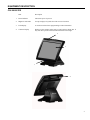
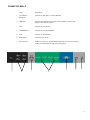
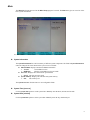
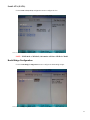
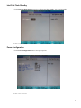
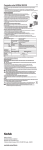
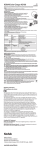
EverServ 500 Users Guide PN770504019 This material has been created in order to accommodate a wide range of restaurant operations and your specific business practices and system configuration may differ slightly from what is represented in this material. While ParTech, Inc. (“PAR”) takes great care to ensure the accuracy of these materials, all material is provided “as is” without warranty of any kind, either express or implied, including, but not limited to, warranties of merchantability or fitness for a particular purpose. PAR does not make any warranties or representations that the materials will meet your requirements or that the operations of the hardware will be uninterrupted or error free. Trademark Notices: The PAR logo, Boundless Hospitality by PAR logo, PAR EverServ™, the PAR EverServ logo and PixelPoint® are all trademarks of PAR Technology Corporation, the parent company of ParTech, Inc. or its affiliates. All other product names used throughout this material are trademarks of the respective companies. No such use of any trademark is intended to convey endorsement or other affiliation with these companies. Reproduction: Copyright © 2014 ParTech, Inc. All rights reserved. This publication, or any part thereof, may not be reproduced or transmitted in any form or by any means, electronic or mechanical, including photocopying, recording, storage in an information retrieval system, or otherwise, without the prior written permission of ParTech, Inc., PAR Technology Park, 8383 Seneca Turnpike, New Hartford, NY 13413-4991; Phone: (315) 738-0600. 2 INTRODUCTION 4 GLOSSARY OF TERMS 4 EQUIPMENTDESCRIPTION 5 SPECIFICATIONS 7 BIOS 8 Introduction Starting Setup Using Setup Getting Help BIOS Menu Bar 8 8 8 8 8 Main 9 Advanced Boot Configuration Processor Configuration North Bridge Configuration South Bridge Configuration SIO Configuration HW Monitor Intel Fast Flash Standby Power Configuration LCD Brightness Configuration 10 11 11 12 13 13 14 15 15 16 Boot 16 Exit 17 3 INTRODUCTION The following guide provides information about the EverServ 500. It is presented in four sections as outlined in the table below. Introduction Register cabling diagram, sample system configurations. Equipment Description Specifications, a detailed description of each system components. Turn On/Off Turning on/off EverServ register. BIOS Provides information on BIOS configurations. GLOSSARY OF TERMS ♦ LCD – Liquid Crystal Display ♦ VGA – Video Graphics Array ♦ EFT – Electronic Funds Transfer ♦ LAN – Local Area Network ♦ DDR – Double Date Rate ♦ POS – Point of Sale ♦ BIOS – Basic Input Output System ♦ PCI – Peripheral Component Interconnect ♦ PnP – Plug and Play ♦ IDE – Integrated/Intelligent Drive Electronics ♦ ACPI – Advanced Configuration and Power Interface ♦ SSD – Solid State Drive 4 EQUIPMENT DESCRIPTION POS REGISTER Item Description 1. Power Indicator Shows that power is present. 2. Magnetic card reader Accepts employee keycards. Provides access to functions. 3. LCD Display A touch screen that shows programming or order information. 4. Customer Display Displays to the customer order total, tax total, and any change due. It may also show present advertisement information or messages. 2 3 1 4 5 CONNECTOR WELLS Item 1 Description 1. Cash Drawer Receptacle Connects to cash drawer. (19V DC/Default) 2. USB Ports Connects to coin dispensers, remote customer displays, remote order displays, EFT devices, printers. 3. LAN Connects to a LAN cable. 4. COM RJ45 Port Connects to external peripherals. 5. VGA Connects to other displays. 6. Power Input Provides power to unit. 7. Power Switch Push in to turn unit on, push and hold to turn unit off. You can reach it by sliding your hand under the right side of the register. 2 3 5 6 7 4 6 SPECIFICATIONS FEATURES Description PROCESSORS: Intel Cedar Trail 1.86 GHz D2550 MEMORY: 2 GB/1066MHz (Up to 4 GB - 1 Slot supported) – (M5100, M5100-01 or M5100-02) 4GB/1066MHz (M5100-03 only) DISPLAYS: 15” XGA LCD Integrated 2x20 LCD Display MAGNETIC STRIP READERS: Built in 3 Track USB Swipe Reader PROGRAM/DATA STORAGE: 320 GB 2.5” SATA HDD – (M5100 or M5100-01 only) 60 GB Minimum SATA SSD – (M5100-02 or M5100-03 only) CASH DRAWER: 19V DC Default Cash Drawer Adapter Cable (C2355) SERIAL PORT ADAPTER: 2- C8200 RJ-50/DB-9 Serial Adapter Cables 7 BIOS Introduction This user manual describes the Phoenix BIOS setup program and configuration options of the EverServ motherboard. The BIOS setup program allows users to modify the basic system configuration of the EverServ motherboard. Starting Setup The PHOENIX BIOS is activated when the computer is turned on. The setup program can be activated in one of two ways. 1. Press the DELETE key as soon as the system is turned on or 2. Press the DELETE key when the “Press Del to enter SETUP” message appears on the screen. 0. If the message disappears before the DELETE key is pressed, restart the computer and try again. Using Setup Use the arrow keys to highlight items, press ENTER to select, use the PageUp and PageDown keys to change entries, press F1 for help and press ESC to quit. Navigation keys are shown in. Key Function Up arrow Down arrow Left arrow Right arrow Esc key Page Up key Page Dn key F1 key F10 key Move to previous item Move to next item Move to the item on the left hand side Move to the item on the right hand side Main Menu – Quit and not save changes Status Page Setup Menu and Option Page Setup Menu -- Exit current page and return to Main Menu Increase the numeric value or make changes Decrease the numeric value or make changes General help, only for Status Page Setup Menu and Option Page Setup Menu Save all changes, only for Main Menu Getting Help When F1 is pressed a small help window describing the appropriate keys to use and the possible selections for the highlighted item appears. To exit the Help Window press ESC or the F1 key again. BIOS Menu Bar The menu bar on top of the BIOS screen has the following main items: Main Changes the basic system configuration. Advanced Changes the advanced system settings. Boot Changes the system boot configuration. Exit Selects exit options and loads default settings The following sections completely describe the configuration options found in the menu items at the top of the BIOS screen and listed above. 8 Main The Main BIOS menu appears when the BIOS Setup program is entered. The Main menu gives an overview of the basic system information. BIOS Menu 1: Main Î System Information The System Information lists a brief summary of different system components. The fields in System Information cannot be changed. The items shown in the system overview include: Phoenix BIOS: Displays auto-detected BIOS information o Version: Current BIOS version o Build Date: Date the current BIOS version was made Processor: Displays auto-detected CPU specifications o Speed: Lists the processor speed System Memory: Displays the auto-detected system memory. o Size: Lists memory size The System Overview field also has two user configurable fields: Î System Time [xx:xx:xx] Î Use the System Time option to set the system time. Manually enter the hours, minutes and seconds. System Date [xx/xx/xx] Use the System Date option to set the system date. Manually enter the day, month and year. 9 Advanced Use the Advanced menu to configure the CPU and peripheral devices through the following sub-menus: WARNING: Setting the wrong values in the sections below may cause the system to malfunction. Make sure that the settings made are compatible with the hardware. Boot Configuration Processor Configuration Serial ATA (SATA) North Bridge Configuration South Bridge Configuration SIO Configuration HW Monitor Intel Fast Flash Standby Power Configuration LCD Brightness Configuration BIOS Menu 2: Advanced 10 Boot Configuration Use the Boot menu to configure system boot options. BIOS Menu 3: Boot Configuration Processor Configuration Use the Processor Configuration menu to configure Processor options. BIOS Menu 4: PROCESSOR Configuration 11 Serial ATA (SATA) Use the Serial ATA (SATA) configuration menu to configure devices. BIOS Menu 5: Serial ATA(SATA) NOTE: If M5100-02 or M5100-03, information will show SSD Drive Model. North Bridge Configuration Use the North Bridge Configuration menu to configure the North Bridge chipset. BIOS Menu 6: North Bridge Configuration 12 South Bridge Configuration Use the SouthBridge Configuration menu to configure the South Bridge chipset. BIOS Menu 7: South Bridge Configuration SIO Configuration The SIO Configuration menu configures LPC settings. BIOS Menu 8: SIO Configuration 13 HW Monitor The HW Monitor menu monitors system voltages and temperatures. 14 Intel Fast Flash Standby Use the Intel Fast Flash Standby menu is to configure Intel Flash Standby, only for AHCI enable. BIOS Menu 9: Intel Fast Flash Stanby Power Configuration Use the Power Configuration menu to select power options. BIOS Menu 10: Power Configuration 15 LCD Brightness Configuration Use the LCD Brightness Configuration menu to select power options for VGA/COM and control LCD Brightness. BIOS Menu 11: VGA/COM Power and LCD Brightness Configuration Boot Use the Boot menu to configure system boot priority options. BIOS Menu 12: Boot 16 Exit Use the Exit menu to load default BIOS values, optimal failsafe values and to save configuration changes. BIOS Menu 13:Exit Î Exit Saving Changes Î Use the Exit Saving Changes option to save the changes made to the BIOS options and to exit the BIOS configuration setup program. Exit Discarding Changes Use the Exit Discarding Changes option to never save the changes made to the BIOS options and to exit the BIOS configuration setup program. Î Load Setup Defaults Use the Load Setup Defaults option to reset all standard default values. Î Discard Changes Use the Discard Changes option to load the original value of this boot time. Î Save Changes Use the Save Changes option to save the changes made to the BIOS options and to not exit the BIOS configuration setup program. 17 SAFETY ♦ Before connecting cables or devices to connector wells, please turn off the power first thus preventing potential ESD damage. ♦ The service related to human safety is not allowed because this device may have the possibility of the radio interference. ♦ As this equipment has undergone EMC registration for business purpose (“A” class), the seller and/or the buyer is asked to beware of this point and designed to be used in the area, except for home use. Battery Warning A lithium coin-type battery is installed on the EverServ 500 motherboard. If this battery is replaced, it must be replaced with an equivalent battery type. Dispose of used battery according to the local disposal instructions. 18 PAR PHONE NUMBERS Service USA: 800.382.6200 Canada: 800.387.4963 Parts USA: 800.PAR.PART Canada: 800.387.4963 Sales Continental USA except New York: 800.448.6505 New York State Only: 800.533.6311 Outside Continental USA: 315-738-0600 Driver Support http://www.partech.com/restaurant/services/contact-support/ 19