1
XGT Panel
XP-Builder
XGT Panel Series
Table of Contents
1. About XP-Builder ................................................................................. 1
1.1 Overview .......................................................................................................... 1
1.1.1 XP-Builder Concept............................................................................................ 1
1.1.2 Supported Hardware Types................................................................................ 3
1.2 Installing and Updating .................................................................................... 4
1.2.1 Installing XP-Builder ......................................................................................... 4
1.2.2 Updating XP-Builder ......................................................................................... 5
1.3 Interface and Features ....................................................................................... 6
1.3.1 The XP-Builder Interface .................................................................................... 6
1.3.2 Controls and Options ........................................................................................ 7
1.3.2.1 Customizing Toolbars...................................................................................... 7
1.3.2.2 Customizing Keyboard Shortcuts.................................................................. 10
1.3.2.3 Customizing Menu Options .......................................................................... 11
1.3.2.4 Customizing Pane Positions ......................................................................... 11
1.3.2.5 Customizing Other Options .......................................................................... 12
2. Project Development .......................................................................... 13
2.1 Creating a project ............................................................................................ 13
2.1.1 Starting a New Project .....................................................................................13
2.1.2 Saving a Project .............................................................................................. 16
2.2 Configuring Project Properties ......................................................................... 17
2.2.1 Protecting the Project with a Password ............................................................ 17
2.2.2 Viewing and Editing Properties....................................................................... 19
2.2.2.1 Changing Basic Project Properties ...............................................................20
2.2.2.2 Changing XGT Panel Settings....................................................................... 21
2.2.2.3 Changing Screen (Window) Settings ............................................................ 23
2.2.2.4 Changing Security Settings .......................................................................... 25
2.2.2.5 Changing Key Window Settings ................................................................... 27
2.2.2.6 Changing Languages ................................................................................... 28
2.2.2.7 Changing Storage Settings ...........................................................................30
2.2.2.8 Changing Global Script Settings ................................................................... 31
2.2.2.9 Changing Auxiliary Settings ......................................................................... 32
2.2.2.10 Changing Extended Controller Settings .....................................................34
2.2.3 Editing default settings .................................................................................. 43
2.2.3.1 Changing default editing options .................................................................43
2.2.3.2 Changing default project options ................................................................ 44
2.3 Developing an Interface ...................................................................................45
2.3.1 Adding Windows or Parts ................................................................................ 46
2.3.2 Configuring Windows...................................................................................... 47
2.3.2.1 Opening or Closing a Window ....................................................................... 47
2.3.2.2 Setting a Window as the Start Window ........................................................ 47
2.3.2.3 Renaming a Window .................................................................................... 48
2.3.2.4 Changing Screen Properties ........................................................................ 49
2.3.3 Editing Windows ............................................................................................ 52
2.3.4 Inserting Figures or Objects ............................................................................. 53
2.3.4.1 Drawing Figures............................................................................................ 53
2.3.4.2 Drawing Objects ........................................................................................... 57
2.3.4.3 Inserting Objects from the Object Library ................................................... 60
2.3.4.4 Managing Object Libraries .......................................................................... 62
2.3.5 Editing Objects ............................................................................................... 69
i
Table of Contents
2.3.5.1 Copying Multiple Objects ............................................................................ 69
2.3.5.2 Arranging Objects ......................................................................................... 72
2.3.5.3 Rotating Objects........................................................................................... 74
2.3.5.4 Resizing or Relocating Objects ..................................................................... 75
2.3.5.5 Setting Viewing Options .............................................................................. 78
2.3.6 Applying Images ............................................................................................. 84
2.3.6.1 Inserting Images.......................................................................................... 84
2.3.6.2 Replacing Images .........................................................................................85
2.3.6.3 Setting an Image as a Background............................................................... 86
2.3.6.4 Managing Image Libraries ............................................................................ 87
2.4 Connecting Controllers .................................................................................. 101
2.4.1 Connecting with Ethernet ..............................................................................101
2.4.2 Connecting with a Serial Port ........................................................................ 104
2.4.2.1 Using RS232C .............................................................................................104
2.4.2.2 Using RS485/RS422 .................................................................................... 107
2.5 Simulating & Debugging ................................................................................ 110
2.5.1 Simulating an Interface .................................................................................110
2.5.2 Inputting Simulated Data ..............................................................................112
2.5.2.1 Monitoring Devices .................................................................................... 112
2.5.2.2 Changing Device Values ............................................................................. 114
2.5.3 Running a Data Check .................................................................................... 115
2.5.4 Viewing the Device Map .................................................................................116
2.5.5 Evaluating Project Size (Memory Usage) ........................................................118
2.5.6 Finding and Replacing Devices .......................................................................119
2.5.6.1 Finding and Replacing Devices on the Active Window................................ 119
2.5.6.2 Finding and Replacing All Devices .............................................................. 121
2.5.6.3 Viewing Device Cross-References ............................................................... 123
2.5.7 Switching Project Windows ............................................................................123
2.6 Managing a Project ........................................................................................ 124
2.6.1 Transferring to an XGT Panel ......................................................................... 124
2.6.1.1 Using a Serial (RS-232C) Connection........................................................... 128
2.6.1.2 Using an Ethernet Connection.................................................................... 130
2.6.1.3 Using a USB Connection ............................................................................. 132
2.6.1.4 Using an ActiveSync Connection................................................................ 134
2.6.2 Transferring to a Removable Drive.................................................................. 135
2.6.3 Receiving a Project File from an XGT Panel ..................................................... 137
2.6.4 Backing up Project Data ................................................................................139
2.7 Configuring Advanced Communication Settings .............................................. 142
2.7.1 Using 1:N Communication with Multiple Protocols ........................................ 142
2.7.2 Using 1:N Communication with RS485 .......................................................... 144
2.7.3 Using N:1 Communication ............................................................................. 146
3. Troubleshooting............................................................................... 150
3.1 Resolving Error Codes Found in the Results Pane ............................................. 152
3.2 Resolving Error Messages in Pop-up Windows .................................................. 161
3.3 Resolving Error Codes during Recording ..........................................................166
3.4 Resolving Other Issues ...................................................................................168
3.4.1 I Cannot Select the HS Internal Device ........................................................... 168
3.4.2 I Cannot Change the XGT Panel Type ............................................................. 168
ii
Table of Contents
3.4.3 I Cannot Select a Communication Protocol .................................................... 168
3.4.4 I Cannot Save Project Properties after Editing Them ...................................... 168
3.4.5 Text does not Display Properly....................................................................... 169
3.4.6 I Cannot Enter Text in another Language ....................................................... 169
3.4.7 I Cannot Invoke Text from a File ..................................................................... 169
3.4.8 The Name of a History Alarm Changes When I Copy and Paste It .................... 169
3.4.9 I Cannot Edit the System Alarm ..................................................................... 169
3.4.10 I Cannot Import a Log or Schedule ............................................................... 169
3.4.11 I Cannot Invoke a Tag from a Tag Table .......................................................... 170
3.4.12 I Cannot Import Common Data Settings ....................................................... 170
3.4.13 I Cannot Transfer a Project (RS-232) .............................................................. 170
3.4.14 I Cannot Transfer a Project (Ethernet) ........................................................... 171
3.4.15 I Cannot Transfer a Project (USB/Serial Converter) ........................................ 171
3.4.16 I Cannot Transfer a Project (Active Sync or Mobile Device Center) .................. 171
3.4.17 I Cannot Update an XGT Panel ...................................................................... 171
3.4.18 I Cannot Receive a Project from an XGT Panel ............................................... 172
3.4.19 I Cannot Retrieve Backup Data from an XGT Panel ....................................... 172
3.4.20 I Cannot Select the Path of a Removable Drive ............................................. 172
3.4.21 I Cannot Download a Project to a Removable Drive....................................... 172
4. Reference ........................................................................................ 174
4.1 Common Data ............................................................................................... 174
4.1.1 Tags ............................................................................................................... 175
4.1.2 Text Tables .................................................................................................... 185
4.1.3 Logging .........................................................................................................191
4.1.4 Recipes ......................................................................................................... 202
4.1.5 Flow Alarms ...................................................................................................207
4.1.6 History Alarms .............................................................................................. 209
4.1.7 Schedules...................................................................................................... 216
4.1.8 Sounds .......................................................................................................... 217
4.2 Scripts........................................................................................................... 218
4.2.1 About Scripts ................................................................................................ 218
4.2.1.1 Understanding Script Commands ............................................................... 220
4.2.1.2 Understanding Device Address Expressions ...............................................224
4.2.1.3 Understanding Constants and Data Types .................................................. 225
4.2.1.4 Understanding Variables ............................................................................ 227
4.2.1.5 Viewing the Script Cross Reference ............................................................228
4.2.2 Creating Scripts ............................................................................................ 228
4.2.2.1 Inserting Scripts .........................................................................................228
4.2.2.2 Using the Script Tool Box ............................................................................229
4.2.2.3 Specifying Local Scripts .............................................................................. 231
4.2.2.4 Specifying Display Change Scripts .............................................................. 232
4.2.2.5 Specifying Schedule Scripts ........................................................................ 234
4.2.2.6 Creating Object Scripts .............................................................................. 235
4.2.2.7 Editing Scripts ............................................................................................ 236
4.2.3 Using Scripts to Control XGT Panel Functions ................................................ 239
4.2.3.1 Understanding System Functions............................................................... 239
4.2.3.2 Understanding Print Functions.................................................................. 240
iii
Table of Contents
4.2.3.3 Understanding Window Change Functions ................................................. 241
4.2.3.4 Understanding Script Functions ................................................................. 241
4.2.3.5 Understanding String Functions ................................................................. 243
4.2.3.6 Understanding Device Functions................................................................245
4.2.3.7 Understanding Communication Functions ................................................. 247
4.2.3.8 Understanding Memory Functions ............................................................ 249
4.2.3.9 Understanding Data Conversion Functions ................................................ 251
4.2.3.10 Understanding Other Functions ............................................................... 252
4.2.3.11 Understanding the Script Watchdog ......................................................... 254
4.3 Objects.......................................................................................................... 255
4.3.1 Lamp Objects .................................................................................................257
4.3.1.1 Bit Lamp ..................................................................................................... 257
4.3.1.2 Word Lamp .................................................................................................263
4.3.1.3 N-State Lamp ............................................................................................. 270
4.3.2 Switch Objects ............................................................................................... 277
4.3.2.1 Bit Switch ................................................................................................... 277
4.3.2.2 Word Switch ...............................................................................................285
4.3.2.3 Change Screen Switch ............................................................................... 294
4.3.2.4 Special Switch ............................................................................................ 301
4.3.2.5 Multi Switch ............................................................................................... 323
4.3.3 Message Objects ............................................................................................332
4.3.3.1 Bit Message ................................................................................................ 332
4.3.3.2 Word Message ............................................................................................ 337
4.3.4 Numeric/Text Objects .................................................................................... 344
4.3.4.1 Numeric Input.............................................................................................344
4.3.4.2 Numeric Display ......................................................................................... 362
4.3.4.3 Text Input.................................................................................................... 373
4.3.4.4 Text Display ................................................................................................384
4.3.5 Window Objects ............................................................................................ 392
4.3.5.1 Bit Window .................................................................................................392
4.3.5.2 Word Window .............................................................................................396
4.3.6 Part Objects .................................................................................................. 402
4.3.6.1 Bit Part ...................................................................................................... 404
4.3.6.2 Word Part .................................................................................................. 409
4.3.7 Animation Object .......................................................................................... 418
4.3.8 Graph Objects ............................................................................................... 420
4.3.8.1 Bar Graph ...................................................................................................420
4.3.8.2 Pie Graph................................................................................................... 428
4.3.8.3 Meter Graph ...............................................................................................436
4.3.8.4 Closed Graph ..............................................................................................443
4.3.8.5 Trend Graph ................................................................................................450
4.3.8.6 Logging Trend Graph ..................................................................................459
4.3.8.7 Logging Scatter Graph ................................................................................ 472
4.3.8.8 Realtime Scatter ........................................................................................481
4.3.9 History Alarm Viewer Object ......................................................................... 491
4.3.10 Data List Object .......................................................................................... 500
4.3.11 Logging Viewer Object ................................................................................. 506
4.3.12 Alarm Navigator Object................................................................................ 513
4.3.13 Recipe Navigator Object ...............................................................................515
iv
Table of Contents
4.3.14 Data List Editor Object ................................................................................ 518
4.3.15 File Recipe Editor Object ...............................................................................523
4.3.16 Clock Object ................................................................................................. 527
4.3.17 Embedded Screen Object ..............................................................................531
4.3.18 Memo Pad Object .........................................................................................533
4.3.19 Movie Player Object .................................................................................... 536
4.4 Using Program Monitor .................................................................................. 539
4.4.1 About Program Monitor ................................................................................ 539
4.4.1.1 PLCs that Support Monitoring .................................................................... 539
4.4.1.2 The Program Monitor Window ...................................................................540
4.4.2 Monitoring Program ..................................................................................... 541
4.4.2.1 Monitoring Programs from the XGT Panel Menu ........................................ 541
4.4.2.2 Monitoring Programs with a Special Switch Object ....................................542
4.4.2.3 Selecting Programs to Monitor ..................................................................542
4.4.2.4 Managing Programs ................................................................................... 543
4.4.2.5 Changing the Display Format ..................................................................... 545
4.4.2.6 Changing the Current Device Value ............................................................546
4.5 Viewing or Changing XGT Panel Information ................................................... 547
5. Managing an XGT Panel .................................................................... 551
5.1 Configuring System Options ........................................................................... 551
5.1.1 Backlight Settings ........................................................................................ 552
5.1.2 Touch Function Settings ................................................................................ 554
5.1.2.1 Setting Touch Sensitivity ............................................................................ 554
5.1.2.2 Touch Calibration ....................................................................................... 555
5.1.3 Adjusting Date and Time ............................................................................... 556
5.1.4 Environment Settings ....................................................................................557
5.1.5 Ethernet settings .......................................................................................... 560
5.1.6 XP-Remote settings ...................................................................................... 561
5.1.7 Sound settings .............................................................................................. 563
5.1.8 Buzzer settings ............................................................................................. 564
5.2 XGT Panel Function Diagnostics ..................................................................... 566
5.2.1 Checking Screen Function ..............................................................................567
5.2.2 Checking Touch Function ............................................................................... 568
5.2.3 Checking Backup Memory ............................................................................. 569
5.2.4 Checking Flash Memory .................................................................................570
5.2.5 Checking CF Card ........................................................................................... 571
5.2.6 Checking Serial Port .......................................................................................572
5.2.7 Checking SD Card ...........................................................................................574
5.2.8 Checking USB Memory ...................................................................................575
5.3 Viewing Controller Information ...................................................................... 576
5.3.1 Changing Settings.......................................................................................... 577
5.3.2 Viewing Connection Information ....................................................................578
5.3.3 Ladder Program Monitoring .......................................................................... 583
5.3.4 Setting Up N:1 Communication ..................................................................... 584
5.4 Updating the XGT Panel .................................................................................586
5.5 Managing Storage Devices..............................................................................588
5.5.1 Downloading Projects ................................................................................... 588
v
Table of Contents
5.5.2 Uploading Projects ........................................................................................ 590
5.5.3 Updating XGT Panel ..................................................................................... 592
5.5.4 Select a USB Storage Device ......................................................................... 594
5.6 Managing External Storage Sources for Backup ...............................................598
5.6.1 Managing the File Path for Backup Files ........................................................ 598
5.6.1.1 File Path for Logging Backup ......................................................................599
5.6.1.2 Path for Recipe Backup.............................................................................. 600
5.6.1.3 Path for Screen Backup.............................................................................. 600
5.6.1.4 Path for Memo Backup ............................................................................... 601
5.6.1.5 Path for Movie Records Backup .................................................................. 601
5.6.1.6 Path for Still Image Backup (Camera and Movie Still Images) .................... 601
5.6.2 Managing Memory for Backups..................................................................... 602
5.6.3 File Path for Video File and Video Capture File Backup ................................... 603
5.6.3.1 When the File Is Added ............................................................................... 603
5.6.3.2 When There is Insufficient Memory or Exceeds the Limit .......................... 604
5.6.3.3 ActiveSync Related Actions ....................................................................... 604
5.6.3.4 When a Storage Device Is Removed ........................................................... 604
5.6.4 Monitoring External Storage Connection ....................................................... 605
5.6.5 Safe Removal Switch .................................................................................... 607
5.7 Installing and Wiring ......................................................................................609
5.7.1 Installing an XGT Panel ................................................................................. 609
5.7.1.1 Surrounding Condition .............................................................................. 609
5.7.1.2 Installation Safety ......................................................................................610
5.7.1.3 XGT Panel – Thermal Control Considerations .............................................. 611
5.7.2 Panel Design and Installation ....................................................................... 612
5.7.2.1 Building a Panel ..........................................................................................612
5.7.2.2 Mounting XGT Panel .................................................................................. 613
5.7.3 XGT Panel Wiring Specifications.................................................................... 615
5.7.3.1 Power Wiring............................................................................................... 615
5.7.3.2 Ground Connection Wiring .........................................................................620
Glossary ............................................................................................... 621
List of Acronyms ................................................................................... 624
Safety and Legal Information ................................................................. 627
Caution: Wiring and Installation .......................................................................... 627
Caution: Usage and Maintenance ......................................................................... 627
Index .................................................................................................... 629
vi
1.
About XP-Builder
1. About XP-Builder
XP-Builder is software that allows you to create and manage projects for machine control devices. You
can use XP-Builder to create projects for the XGT Panel. XP-Builder includes multiple features that
allow you to design and edit projects conveniently, such as:
• Customizable toolbars and hotkeys
• Customizable tool, project, and editing panes
• Functions to import and export common data
• Tabs for viewing multiple windows easily
• Previews of project windows
• Customizable image and object libraries
• Scripts and advanced functions, such as alarms, logs, schedules, and recipes
• Multiple language support
1.1 Overview
This section describes the basic concept of using XP-Builder to create interfaces for machine
control devices and the types of hardware that XP-Builder supports.
1.1.1 XP-Builder Concept
XP-Builder is the starting point for creating human-machine interfaces (HMIs) for industrial
applications. With XP-Builder, you can design user-friendly interfaces for XGT Panels that
allow end users to control machine functions through configurable controllers, such as
programmable logic controllers (PLCs), inverters, or servos.
With the XGT Panel, you can monitor information from each controller via a graphical user
interface (GUI). In addition, simple control is possible with switch and writing objects. The
XGT Panel supports additional programmable functions, such as scripts, loggings, recipes, and
alarms, which allow you to fully customize the control environment.
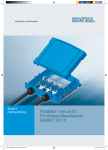
As illustrated by the graphic that follows, the interface running on an XGT Panel provides
input controls, in the form of bit objects that are linked to controller routines, such as a ladder
program, or other parameters. The controller parameters dictate the operation of connected
machinery and may also provide feedback to the XGT Panel. Data returned from a monitoring
process can be displayed on the XGT Panel, in the form of word devices.
1
1.
About XP-Builder
2
1.
About XP-Builder
1.1.2 Supported Hardware Types
XP-Builder supports XP and iXP series XGT Panels and a wide range of controllers. Projects
can be transferred from XP-Builder only to XGT Panels manufactured by LSIS. To view
specifications for XGT Panels, in XP-Builder, click [Project] ▶ [New Project], and then select a
series and model number from the drop-down lists.
Note
• The iXP series XGT Panels are supported by XP-Builder versions 1.30 or higher.
• Available memory for XP series XGT Panels is 10MB for TTA models, with the exception
of the XP90 model (20MB), and 4MB for TTE models.
• Available memory for iXP series XGT Panels is 128MB.
3
1.
About XP-Builder
1.2 Installing and Updating
This section explains how to install and update the XP-Builder software, as well as the operating
system software for an XGT Panel.
1.2.1 Installing XP-Builder
You may install XP-Builder on a PC that meets the following minimum system requirements:
Processor: Pentium 4 or higher
Memory: 512MB or more free memory
COM Ports: RS-232C serial port, Ethernet port, or USB port
Hard Disk: 1GB capacity or higher
Monitor: Minimum resolution of 1024x768
OS: Windows XP, Windows Vista, Windows 7, or Windows 8
Peripherals: Mouse and keyboard
To install XP-Builder in Windows XP:
1. Run the XP-Builder setup file. You can download the file from the LSIS website
(http://eng.lsis.biz/support/download/).
2. Select an installation language (Chinese [Simplified], English, or Korean).
3. Follow the instructions in the installation wizard to complete the installation.
To install XP-Builder in Windows Vista:
1. Log in to your computer with an administrator account.
2. On your computer, click [Start] ▶ [Control Panel] ▶ [User Accounts and Family Safety].
3. Click [User Accounts] ▶ [Turn User Account Control on or off], and uncheck the tick box
next to Use User Account Control (UAC) to help protect your computer.
4. Run the XP-Builder setup file. You can download the file from the LSIS website
(http://eng.lsis.biz/support/download/).
5. Select an installation language (Chinese [Simplified], English, or Korean).
6. Follow the instructions in the installation wizard to complete the installation.
4
1.
About XP-Builder
To install XP-Builder in Windows 7 or Windows 8:
1. Log in to your computer with an administrator account.
2. On your computer, click [Start] ▶ [Control Panel] ▶ [User Accounts and Family Safety].
3. Click [User Accounts] ▶ [Change User Account Control Settings], and drag the slider to
Never notify.
4. Run the XP-Builder setup file. You can download the file from the LSIS website
(http://eng.lsis.biz/support/download/).
5. Select an installation language (Chinese [Simplified], English, or Korean).
6. Follow the instructions in the installation wizard to complete the installation.
1.2.2 Updating XP-Builder
To check the version of your XP-Builder software, click [Help] ▶ [About XP-Builder]. To
update XP-Builder refer to the LSIS website (http://eng.lsis.biz/support/download/).
Note
You can update an XGT Panel automatically in XP-Builder version 1.30. If you use a version
lower than 1.24, you must update the XGT Panel manually.
5
1.
About XP-Builder
1.3 Interface and Features
XP-Builder offers a wide range of customizable options that allow you to efficiently create and
manage projects. This section describes the XP-Builder interface and explains how to customize it
to suit your needs.
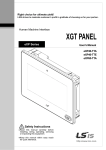
1.3.1 The XP-Builder Interface
The XP-Builder interface is similar to that of many Windows-based programs. You can
customize the interface by selecting various toolbar and window options, as described in
<1.3.2
Controls and Options>.
Toolbars
Editing area
Toolbox
Project
pane
Output and
results tabs
Interface
Description
Toolbars
Use tools or menus to perform tasks and specify options.
Project pane
Show the elements contained in the project in a cascading tree. You
can open, reposition, or dock other windows, such as the Graphic
Library, Object Library, Device Map, Script Toolbox, and Data Viewer
windows.
Editing area
The center of the window, where you can add and manipulate objects,
figures, and graphics to create an interface.
Toolbox
Use the objects or figures in the Toolbox to create a project.
Output and
results tabs
These tabs allow you to view interface messages, error messages, and
search results.
6
1.
About XP-Builder
1.3.2 Controls and Options
Customize toolbars, keyboard shortcuts, menus, and other options in the XP-Builder interface.
1.3.2.1 Customizing Toolbars
In the XP-Builder interface, you can create custom toolbars, add or remove icons on
toolbars, and select which toolbars to show.
To create a toolbar:
1. Click [Tool] ▶ [Customization] ▶ [Toolbars].
7
1.
About XP-Builder
2. Click [New].
3. Enter a name for the toolbar and click [OK]. The new toolbar will be added to the list
of available toolbars on the left of the Customize window. You can drag icons from the
toolbars at the top of the XP-Builder window to the new toolbar.
8
1.
About XP-Builder
To add or remove icons on toolbars:
1. Click [Tool] ▶ [Customization] ▶ [Commands].
2. Click a tool category on the left, and then drag and drop a command onto an existing
toolbar. Or, to remove an icon, drag it from a toolbar to the Customize window.
To select which toolbars to show:
1. Click [Tool] ▶ [Customization] ▶ [Toolbars].
9
1.
About XP-Builder
2. Click the checkboxes to the left of the toolbars to select which to show (checked) and
which to hide (unchecked).
1.3.2.2 Customizing Keyboard Shortcuts
To customize keyboard shortcuts (hotkeys):
1. Click [Tool] ▶ [Customization] ▶ [Keyboard].
2. Click a tool category from the drop-down list, and then click a command.
3. Click the Press New Shortcut Key field and then press a key combination on the
keyboard. If you press a combination that is already in use, the action that is assigned
to the shortcut will appear below this field.
4. Click [Assign].
5. To remove a shortcut, select one from the Current Keys field and then click [Remove].
6. When you are finished customizing keyboard shortcuts, click [Close].
10
1.
About XP-Builder
1.3.2.3 Customizing Menu Options
In the Customize window, you can select which Application Frame windows and Context
menus to show. To customize menu options, click [Tool] ▶ [Customization] ▶
[Menu], and then select the desired options from the drop-down menus.
1.3.2.4 Customizing Pane Positions
To view or hide panes, click [View], and then click the name of a pane. You can drag and
drop panes in new positions within the XP-Builder window. To change properties for a
pane, right-click the pane and click an option. You can set panes to dock or float and set
whether or not the pane will hide automatically.
To dock the pane, move the pane to the desired location indicator. A shadow will appear
to provide a preview of the docking location. To set a pane to float, on the pane, click
▶ [Floating]. To hide a pane, on the pane, click
11
.
1.
About XP-Builder
1.3.2.5 Customizing Other Options
In the Customize window, you can customize additional options, such as whether or not
to show tool tips, use large icons, and show the most recently-used commands first in
menus and toolbars. To customize these options, click [Tool] ▶ [Customization] ▶
[Options], and then click the checkboxes next to the desired options.
12
2.
Project Development
2. Project Development
XP-Builder allows you to develop complex, but simple-to-use interfaces for controlling machines. You
can add figures, objects, and graphics to represent functions or use scripts to define processes. XPBuilder also allows you to simulate projects and debug them before transferring them to an XGT Panel.
2.1 Creating a project
Learn how to start or open a project.
2.1.1 Starting a New Project
To create a new project:
1. When you launch XP-Builder, the Select Project window appears. Click [Create Project] to
create a project.
To open a saved file, select [Open Project].
You can also create a file by selecting [Project] ▶ [New Project].
13
2.
Project Development
2. Set the panel series, model name, the controller manufacturer, and the controller model
(Product).
3. If necessary, click [Communication Settings] and specify connection properties. For more
details about connection properties, refer to <2.4
Connecting Controllers>
4. Click [Finish] or [OK].
Notes
• You can view XGT Panel specifications when you create a project by selecting the XGT
Panel series and model.
• If the computer or panel you are working with does not have the font installed, data
may not be represented properly. To solve this problem, install or export fonts as
14
2.
Project Development
needed: click [Tool] ▶ [Install Font] or [Export Font], specify a file location, and click
[OK].
• Project files in XP-Builder are saved with the extension “.xpd.” You can only import
these types of project files to XP-Builder.
• The file extension for the executable file transferred to an XGT Panel is “.hmi.”
• The file extension for the user object library is “.xpo.”
• The file extension for the user graphic library is “.xpg.”
• The extensions for common data types are shown in the following table:
15
Item
File Extension
Text table, Recipe, and Tag
*.CSV
History alarm
*.HAL
Flow alarm
*.FAL
Logging
*.LOG
Scheduler
*.SCH
Script
*.SPT
2.
Project Development
2.1.2 Saving a Project
To save a project:
1. Click [Project] ▶ [Save Project].
You can also select the save project icon
from the toolbar.
To save the file with another name, select [Project] ▶ [Save as Project]
2. Select a destination for the saved file, enter a file name, and click [Save].
Notes
• When you save a project, two other files are created:
- Backup file: The extension for the backup file is “.bak.”
- OSTS file: The extension for the OSTS file is “.OSTS.” This file includes information
about your project workspace, such as the current screen, docked windows, and
toolbar information.
• When your project contains unsaved changes, the Project pane shows an asterisk (*)
next to the project name.
3. To close the project, click [Project] ▶ [Close Project].
16
2.
Project Development
2.2 Configuring Project Properties
Set the properties or parameters for the project file. Specify properties for connecting with XGT
Panels, window settings, security levels, languages, and more.
2.2.1 Protecting the Project with a Password
You can prevent others from opening a project by setting a password.
1. Click [Project] ▶ [Project Password].
2. Enter a password and re-enter it to confirm.
3. Click [Apply].
Notes
• XP-Builder supports only Latin characters in passwords. Passwords are case
sensitive and can be up to 12 characters long.
• Be careful not to forget the password. If you forget the password, you cannot
open the project file.
17
2.
Project Development
To change a password:
1. Click [Project] ▶ [Project Password].
2. Enter the current password in the Old Password field.
3. Enter a new password and re-enter it to confirm in the New Password field.
4. Click [Apply].
To delete a password:
1. Click [Project] ▶ [Project Password].
18
2.
Project Development
2. Enter the current password in the Old Password field.
3. Click [Delete].
2.2.2 Viewing and Editing Properties
XP-Builder allows you to view and edit general properties for projects. To view or edit project
properties, click [Common] ▶ [Project Property Setting]. From the Project Property window,
you can view or edit the following properties:
19
Tab
Description
Summary
Basic information for the project file, such as the project
name and author
XGT Panel Settings
XGT Panel information and communication methods
Screen Settings
Window change options
Security Settings
Permissions for connected XGT Panels
Key Window Settings
Settings for key windows
Language
Editing language and runtime language options
Storage Settings
Destination and backup locations for project components
and XGT Panel data
Global Script Settings
Global options to apply to scripts
Auxiliary Settings
Options for printing, capturing screens, displaying flow
alarms, sending email alerts, displaying system alarms, and
displaying communication errors
Extended Controller
Settings
Settings for barcode readers
2.
Project Development
2.2.2.1 Changing Basic Project Properties
The Summary tab in the Project Property window contains basic information, such as the
project name, file path, author, creation date, modification date, last download date,
version, and project description. To change basic project properties, edit the information
in the appropriate field and click [OK]:
Item
Description
Project
Name
The project name does not have to match the file name. The file name
you specify will appear at the top of the project tree in the Project
pane.
File Path
The location of the project file (this cannot be edited)
Author
The creator of the file
Description
A description of the project
Created
The date the file was first created (this cannot be edited)
Modified
The date the file was last modified (this cannot be edited)
Downloaded
The date the project was last downloaded to an XGT Panel (this cannot
be edited)
Version
The version of the XP-Builder software (you can change this
information to create a unique identifier for customized properties)
20
2.
Project Development
2.2.2.2 Changing XGT Panel Settings
Edit the XGT Panel and model type. You can also set the connection method settings for
connecting to controllers. The options vary by the connection method. To change XGT
Panel settings, edit the information in the appropriate field and click [OK]:
XGT Panel Settings
Description
Series
• Select an XGT Panel type. The initial information is the
same as you selected when you created the project.
• iXP series allow you to select color mode and power supply
options as well.
Model
Select a model number, based on the XGT Panel type you
selected.
24 BIT Color Mode
This mode is supported only by iXP series. Select this option to
use 24-bit color instead of the default setting (65,536 colors).
24-bit mode improves the appearance of images on the screen,
but may result in slower screen refresh speeds.
RS-232C 5V Power
Supply
This mode is supported only by iXP series. Select this option to
use the RS232C connection (5V, 250mA) as the power supply.
Add Controller
This mode is supported only by iXP series. You can connect
controllers with multiple protocols, including RS232C,
RS422/485 or Ethernet.
Delete Controller
21
2.
XGT Panel Settings
Project Development
Description
• Click [Add Controller] to insert a new controller tab. The
connection number for the new controller will be one
higher than the previous controller’s connection number
automatically. XP series panels support up to 4 connection
numbers (0-3) and iXP series support up to 16 connection
numbers, depending on the connection protocol you use.
Using 1:N
For more information, refer to <2.7.1
Communication with Multiple Protocols>.
• Click a controller tab and then click [Delete Controller] to
delete it. This option is active only after you have added at
least one controller.
• Connection numbers are automatically renumbered when
a controller is deleted. For example, if you have 3
controllers (numbered 0-2) and you delete controller 1, the
last controller will be renumbered from 2 to 1
automatically.
Controller Settings
Set the controller manufacturer and controller type (Product).
Refer to Manual
Click to open the reference manual for the selected controller.
Protocol
Set the connection method between the XGT Panel and the
controller. Ensure that the setting matches the actual
connection between the XGT Panel and the controller.
Detail Settings
Click to set detailed connection parameters. If a controller is
selected, the default properties will be set automatically. The
options available vary by the connection type.
Timeout
Set a network timeout.
Wait to Send
Set the length of time to wait for network communication
between the XGT Panel and the controller.
Retry Count
Set the number of times to retry when communication fails
between the XGT Panel and the controller.
Use XG5000
Simulator
Set whether or not to use the simulator. To run the simulator,
click [Tool] ▶ [Simulation]. For more information, refer to
<2.5.1
Program Monitor
Simulating an Interface>.About XP-Builder
Set whether or not to view controller data with the Program
Monitor (supported only by XGK series PLCs). For more
22
2.
Project Development
XGT Panel Settings
Description
information about using the Program Monitor, refer to <0
Using Program Monitor>.
Notes
• You can only change properties for an XGT Panel when the mode selected supports the
same color specifications as the panel.
• When changing the XGT Panel type, the height and width of objects vary by resolution.
Objects with fixed sizes and fonts are not affected by changes of the panel type.
• When transferring images to 256-color or economy panels (XP30-BTE and XP30-BTA),
the images are converted to grey scale.
2.2.2.3 Changing Screen (Window) Settings
You can specify the window that appears when an XGT Panel is switched on and settings
for how and when the interface changes. To change window settings, edit the
information in the appropriate field and click [OK]:
23
Screen Settings
Description
Initial Screen Number
• Set the number of the window that appears when the
XGT Panel is switched on.
2.
Screen Settings
Project Development
Description
• If no window is specified, an error will occur.
• To specify the start window, click [Browse] ▶ a
window ▶ [OK].
Screen Change by Device
Set whether or not to switch windows based on the device
value. If you do not use a device to switch windows, the
device value will be changed when the window is
switched.
Change to Screen
Number
Set the device to switch to a specified window. When the
device value changes, the window specified by the device
value will be activated (unsigned, 16 bit).
Current Screen Number
Set a number for the current window.
Global Window 1 Number
Global Window 2 Number
Specify one or two windows that will be activated
“globally”—across the entire interface—based on the
device value. Windows specified here are called based on
the specified device values and have no priority over each
other.
24
2.
Project Development
2.2.2.4 Changing Security Settings
You can change security settings for a connected XGT Panel to regulate access by
different types of users. XGT Panels support 10 security levels (0: lowest to 9: highest). To
change security settings, edit the information in the appropriate field and click [OK]:
25
Security Settings
Description
Password Mode
Set to require a password to access the panel. Enter the
passwords in the Password field for the corresponding security
level.
Password Device
Mode
Set to use a word device to control access to the XGT Panel.
Authentication is initiated by user input, but the first 12 bytes
of data in the device (max) specifies the password. You can use
this feature to provide encrypt authentication or change
authentication parameters frequently.
Security Level
Set passwords for security levels, as desired. Level 0 allows
access by all users, so it is not possible to specify a password
(only levels 1-9 are configurable).
Password
Set a password. XP-Builder supports only Latin characters in
passwords. Passwords are case sensitive and can be up to 12
characters long.
2.
Project Development
Security Settings
Description
Password Device
Set a word device to control access to the XGT Panel. Enter a
device address or click the field, and then click the keypad icon
on the right side of the field to specify a device address.
Password Input
Interval(min)
• Set the length of time to grant access after entering the
password. The permission will expire based on your setting
and will require the password to be re-entered. The default
unit is minute and you can set an interval from 0 to 30
minutes.
• If you set the interval to “0,” a password must be entered for
every operation where a security level is applied.
• If you attempt to access an option that has a higher security
level applied, you must enter the password, even when the
password input interval has not yet expired. For highly
sensitive operations, use shorter intervals.
Note
You can apply security settings to the following objects: bit switch, word switch,
change screen switch, special switch, multi switch, numeric input, and text input.
26
2.
Project Development
2.2.2.5 Changing Key Window Settings
You can set the key window number for input devices. The key window set here is applied
as the default for all key windows. To change key window settings, click the arrow
or
) to select a new window number or click [Browse] and then click a
buttons(
key window type.
27
2.
Project Development
2.2.2.6 Changing Languages
From the Language tab, you can edit both display and runtime language settings. To
change language settings, edit the information in the appropriate field and click [OK]:
Language Settings
Description
Editing Language List
• Set the display language.
• Languages shown in text tables are set here.
Add New
Click to add additional display languages to the
interface. Select a language from the list and then click
[OK] to add it to the Editing Language List.
Delete
Select a language, and then click to remove it.
Editing Languages Settings
Change the default fonts for each editing language.
28
2.
Project Development
Language Settings
Description
Multilingual Font
• Set a font to transfer with the project file. This
function is useful when the XGT Panel does not
support Asian characters, such as in the case of XP
series panels that run the Windows CE operating
system.
• If you select this option, the entire font will be
transferred to the panel. Ensure that the size of the
font file does not exceed the available memory of
the XGT panel model.
Runtime Language List
View and specify runtime languages to use with the
project. You can add or remove languages that will be
shown in the project.
Language Change by Device
Set the runtime language to change for specific
devices. The XGT Panel reads the value from the device
and displays the interface in the language you specify
in the Runtime Language List.
Device
Select a word device.
Default Runtime Language
Set the runtime language that will be used by default
on the XGT Panel.
Notes
• Text may not be displayed properly if the text cannot be represented by the
default font.
• If you set the language to change by device, you must designate a language for
the device or nothing will be shown in the XGT Panel.
29
2.
Project Development
2.2.2.7 Changing Storage Settings
Set the storage locations for image and font files, as well as the locations for backing up
logging data recipes, and screen captures from an XGT Panel.
Storage Settings
Description
Image Files
• XGT Panel has a fixed amount of memory for saving
project files.
• If you want to download XGT Panel data that exceeds the
size of the allocated memory, you can save files on
removable media.
• Use the entire path to specify the storage file path on the
XGT Panel.
Upload Project File
Specify locations where files are stored.
Sound Files
Recipe Data
Alarm Data
Logging Data
Recipe Data
Capture Image
Memo File
Video File
Video Capture Image
Specify an external location where the data will be backed
up. If disk is full, existing data will be overwritten.
30
2.
Project Development
Notes
• XGT Panels support three types of removable storage devices: USB devices, CF
cards, and SD cards (iXP only).
• X30-BTE, XP30-TTE, XP40-TTE, XP40-TTA, and XP50-TTE models do not support
CF cards.
2.2.2.8 Changing Global Script Settings
Global script conditions are monitored through an XGT Panel and executed if the
conditions are met. Up to 8 global scripts can be created. If two or more conditions are
met simultaneously, scripts are executed based on the priority that you specify.
Global Script Settings
Description
Name
Set a script name.
Device
Set a bit device that meets the conditions required to
execute the script.
Type
Choose a trigger type for executing the script (Rising edge
or Falling Edge).
Insert, Delete, Modify
Click to insert, delete, or modify global scripts.
Up
Specify the execution priority for when two or more
conditions are met simultaneously.
Down
31
2.
Project Development
2.2.2.9 Changing Auxiliary Settings
You can set the printing direction, locations for saving screen captures, and properties for
the system alarm display.
Auxiliary Settings
Description
Printing Direction
Set the print options such as direction, color, and
whether or not to use the high quality printing.
Screen Capture
Set the action that occurs when the screen is captured
on the XGT Panel. You can save the image in a file or
print it.
Flow Alarm Display Mode
• Set to display the alarm message for the states of
the flow alarm.
• When a flow alarm occurs and is then reset while
the alarm message is displayed, you can specify one
of two actions to occur:
- Redraw at occurred: The alarm message is
replaced automatically with a new message.
- After current display list: The alarm message
remains on the screen and new alarms or reset
alarms will be shown by subsequent messages.
E-mail Property
• Set whether or not to use email alerts.
• Click Server Settings to set email settings. When
32
2.
Project Development
Auxiliary Settings
Description
specifying settings, keep the following in mind:
- You can specify only one email recipient or CC
recipient.
- The email server must be on the same intranet
as the XGT Panel.
- An XGT Panel uses the Anonymous account.
When you set the email server, set to use the
email relay function of the Anonymous account.
- The email is encoded in Unicode.
- Use port number 25 (the default port) for the
email function.
System Alarm Window
Set whether or not to display system alarm messages.
Communication Error
Display
Set whether or not to display communication error
messages on top of other windows.
Note
To configure the email server, click [Server Settings] ▶ [Mail Server].
33
Function
Description
IP Address or SMTP
Server Name
Enter the IP address or SMTP server name.
SMTP Server Port
Enter the port number of the SMTP server. If you use an anonymous
SMTP account service in the intranet, the port number is 25.
Use SSL/TLS
Encode data when transferring it to the mail server.
Validate Server
View the certificate of the mail server.
2.
Project Development
Certificate
My SMTP Server
Requires
Authentication
Unless you use an anonymous SMTP mail service in the intranet, you
need authentication for the user information.
User Name
Set the name for authent ication.
Password
Set the password for authentication.
2.2.2.10 Changing Extended Controller Settings
You can connect a bar code reader to an XGT Panel’s RS-232C port (COM2) and use video
functions.
From the Project Property window, you can view or edit the following properties for a
barcode reader that is connected to an XGT Panel:
Item
Description
Barcode Settings
Set to connect barcode reader to XGT Panel.
Connection Property
Set to use the barcode through the RS-232C protocol.
Detail Settings
Set detail connection options:
• Bytes to read: Set the amount of data to read from a
barcode. If you set the number of bytes, the XGT Panel
reads only the specified number of bytes. If you don’t
specify this setting, the XGT Panel reads the entire
34
2.
Project Development
Item
Description
barcode.
• Save data in: Set a location for saving barcode data. Data
is saved from the specified device continuously.
• Read complete device: Set to display a message when all
data has been read.
• Set the RS-232C communication parameter, such as the
baud rate, data bits, and flow control.
Note
The baud rate must match the setting in the XGT
Panel. To change the baud rate on the XGT Panel,
touch and hold the screen to access the menu. Then,
touch [Setting] ▶ [PC Conn Setting]. For iXP series
XGT Panels, the IP address is set by default.
35
Use Video
Set to use the video option.
Recording Screen Size
Select a screen size for the recorded file.
Recording Frame Rate
Set the number of frames per second to record.
Recording Bit Rate
Set the bit rate.
Video Input Screen
Size
Set a screen size for displaying the recording screen.
Video Capture Screen
Size
Set a screen size for capturing the screen.
Recording Settings
Set the properties for saving the recorded file.
Image Settings
Set the properties for recording quality.
2.
Project Development
Notes
• The higher the frame rate and bit rate, the higher the quality of video that will be
recorded.
• Bigger recording screen and video input screen sizes and higher frame rates and
bit rates may reduce the quality of the video displayed on the XGT Panel.
• You cannot create other objects on the same screen as a movie player object.
Doing so may disrupt communication with the XGT Panel.
• This option is supported only by iXP multimedia type.
To connect a bar code reader:
1. Select [Common] ▶ [Project Property Setting] ▶ [Extended Controller Settings].
2. Click the checkbox next to Barcode Settings.
3. Click [Detail Settings] and specify the following settings:
Item
Description
Bytes to Read
Set the amount of data to read from the bar code. If you
leave this setting unspecified, all data (up to 255 characters)
will be transferred from the bar code reader.
Save Data In
Select a location for saving barcode data.
Data Storage
Enter the first device to receive data from the bar code.
Read Complete Device
Turn on the assigned device when data read from the bar
code has been saved.
Baud Rate
Data Bits
Set the RS-232C communication parameters to match the
bar code reader.
36
2.
Project Development
Item
Flow Control
Parity
Stop Bit(s)
Description
Note
The baud rate must match the setting in the XGT Panel.
To change the baud rate on the XGT Panel, touch and
hold the screen to access the menu. Then, touch
[Setting] ▶ [PC Conn Setting]. For iXP series XGT
Panels, the IP address is set by default.
To use the video option, click the check box next to Use Video. For more detail about the
video option, refer to <4.3.19 Movie Player Object>.
You can set the video save options:
Save Settings
Description
Max. File Size
Set the maximum size for video files (1–512 MB).
Max. Save Time
Set the maximum length for videos (5–3600 seconds [1 hour].
Recording Trigger
Device
Set a bit device to start or stop recording. When the device is
turned “On,” recording starts and when the device is turned
“Off,” recording stops.
Status Device
Set a word device to control video recording. Consecutive
devices will include the following information:
• For devices “HW0000” to “HW0004”
HW0000
37
Status of video recording
2.
Save Settings
Project Development
Description
HW0001
Error codes during recording
HW0002
Video recording file number
HW0003
Video capture file number
HW0004
Video capture error codes
- Video recording status:
0 bit
(HW0000.0)
“On” when recording
1st bit
(HW0000.1)
“On” when playing the video
2nd bit
(HW0000.2)
• “On” when exceeding the maximum
number of saved videos
• It becomes “Off” in the following
situations:
- When starting the recording
process
- When starting to collect the video
file list
- When deleting video files from the
storage device
3rd bit
(HW0000.3)
• “On” when exceeding the maximum
number of video capture files that can
be saved (there is not enough free
space in the backup route or total
number of files is 1000). However, if
you have set to delete old files when
there is not enough storage space,
“On” will not appear.
• Turns “Off” in the following situations:
- When creating the video capture
file
- When starting to collect the video
capture file list
- When deleting video capture files
from the storage device
4th bit
(HW0000.4)
• “On” when an error occurs while
recording, playing, or creating the
38
2.
Project Development
Save Settings
Description
video capture file.
• When an error occurs while creating
the video capture file, the code is
stored by the error code saving device
(HW0004).
• Turns “Off” when you turn off camera
features:
- When starting the recording
process
- When the recording process is
stopped or completed
- When creating the video capture
file
- When playing the video
- When playback is stopped or
completed
- When installation of a storage
device for video files and capture
files is complete
5th bit
(HW0000.5)
“On” when collecting the video file list
6th bit
(HW0000.6)
“On” when collecting the video capture
file list
- For more information about error codes during recording,
refer to <3.3 Resolving Error Codes during Recording>
39
Use Event
Recording
Set to use event recording options.
Event Recording
Trigger Device
Set a bit device to record the previous and post situations for
the event. When the device turns “On,” recording starts.
Recording ends after the designated interval.
Event Recording
Time
Set recording intervals and the pre and post time (5–60
seconds).
Stop Device of
Event Recording
Standby
Set whether or not to stand by for interval recording. In case
of Off > On, stand-by is stopped, and in case of On > Off,
stand-by is started.
2.
Save Settings
Project Development
Description
While standing by, video cannot be played or captured. If you
want to play video or create a capture file while standing by,
set the interval recording stand-by device to “Off.” In such
cases, interval recording is not available, so if you want to
continue with interval recording, set the device to “On.”
You can change properties for input video images.
Function
Description
Brightness
Set brightness of the input video.
Contrast
Set contrast of the input video.
Color
Set color of the input video.
Notes
• This option is supported only by iXP multimedia type.
• In the following situations, recorded video cannot be played and the current
camera input cannot be captured:
- When recording is in progress
- When designating a stop device for event recording standby and and interval
recording start time greater than 0. But when the device is “On,” playing video
and creating capture files is possible, while recording is not. When the device is
“Off,” interval recording is possible while playing videos and creating capture
files are not.
• If recording is in progress, a video cannot be played back.
• You cannot play video on a Window screen and a default screen at the same time.
• You cannot preview a camera on a Window screen and a default screen at the
same time.
• Video capture files can be created only once per second. In other words, even if
40
2.
Project Development
you trigger video capture special switch several times very quickly, only one file
per second will be created.
• You cannot use video functions while creating a list of stored video files and video
capture files. The process of creating a file list may take several seconds to
several minutes. While a video file list is being created, the 4th bit of the status
device stays “On.” While the video capture file list is being created, the 5th bit of
the status device stays “On.” At these times, you can watch the camera input
screen and start or stop monitoring the screen.
• Creation of video file lists and video capture files can happen in the following
situations:
- When starting the monitoring
- When connecting the a computer and XGT Panel via ActiveSync and then
canceling the connection
- When the storage device is installed
• When the safe removal switch is turned on, the switch lamp will be turned off
when all applicable actions are complete in the following situations:
- If the safe removal switch is turned on while the file list was being created, the
switch will be turned off when the file list is complete.
- If the safe removal switch is turned on while recording, the switch will be
turned off when the recording is complete.
- If the safe removal switch is turned on while playing the video, the switch will
be turned off when the file was played completely.
- If the safety removal lamp is turned off, because the safe removal switch was
activated, recording cannot be started and a video capture file cannot be
created.
• Be careful when setting the Event recording trigger device:
- Case 1: If the Event recording trigger device is On (Bit device) after the XGT
Panel monitor is turned on and the Event recording time (Before) has passed,
the event recording will start when the device is triggered and the duration is
based on the Before and After values set in the Event recording time. For
example:
41
2.
Project Development
With these settings, the event recording will occur as follows:
File 1: 0-10 seconds (10 second event)
File 2: 10-20 seconds (10 second event)
File 3: 20-30 seconds (10 second event)
- Case 2: If the Event recording trigger device is turned On (Bit device) while the
XGT Panel monitor is turned on, but the Event recording time (Before) has not
passed, in this case, the event recording starts as soon as the XGT Panel
monitor is turned on and the duration is based on the After value set in the
Event recording time. For the same condition as case 1, the event recording
will occur as follows:
File 1: 0-10 seconds (10 second event)
File 2: 10-15 (5 second event)
• Status device values are updated only in the following situations. So, if you
change the value randomly, the new value will be reflected:
- While recording, the device (Bit) is updated only when the recording is started
or stopped.
- If the storage device recognizes that the memory is exceeded when the
recording is started or while making a list or files saved in storage device or
while recording, the second bit of the status device (Video recording status
device) is updated.
- The bit of the status device is updated when the playback is stopped by a user
or when the playback comes to an end.
• During event recording, an error less than 1 second long may occur because of a
connection to the device or a system load of other actions. It may result when
creating a file with less than 1 second play time. If the play time is less than 500
ms, the file is deleted automatically. When the file is saved separately, based on
the maximum file size, an error of approximately 100kb may occur because of
characteristics of the H.264 codec.
42
2.
Project Development
2.2.3 Editing default settings
You can edit default settings in XP-Builder.
2.2.3.1 Changing default editing options
Change the editing options. Click [Tool] ▶ [Option] ▶ [Edit Option].
43
Item
Description
Object ID/Address Text
Color
Set the default color for device and object IDs. The
setting is applied immediately.
Background
AlphaBlend Use
Set a semi-transparent background for device or object
IDs. The setting is applied immediately.
Object ID/Address Font
Size
Set the default font size for device and object IDs. The
setting is applied immediately.
Default Text Color of
Figure/Object(D)
Set the default font color for character strings in
figures or objects. The setting is applied when you
create new figures or objects.
Default Line Color of
Figure/Object
Set the default line color for character strings in figures
or objects. The setting is applied when you create new
figures or objects.
Use Background Color
from New Screen
Set a background color to use for new windows. The
setting is applied when you create a new window.
2.
Project Development
Item
Description
Default BG Color from
New Screen
Select the default background color. The setting is
applied when you create a new window.
Screen Limit Check on
Object/Figure’s Editing
Prevent figures and objects from extending beyond the
boundaries of the editing area. The setting is applied
immediately.
2.2.3.2 Changing default project options
To edit project management properties, click [Tool] ▶ [Option] ▶ [Project].
Item
Description
Show File Dialog at Start
Up
Set whether or not to show the Select Project window
when you launch XP-Builder.
Recent Files
Set the maximum number of recent files to show.
Auto Save
Set whether or not to save project files automatically.
Interval
Set how often XP-Builder will automatically save project
files.
Show Property Dialog on
New Figure/Object
Set to show the properties window when you create a
new figure or object.
Show Warning On Data
Check or Script Check
Set whether or not to show a warning message and list of
errors in the following instances. If you do not use this
44
2.
Project Development
Item
Description
option, only the warning message will appear.
• When you run a data check ( [Tool] ▶ [Data Check]).
• When you download a project file to an XGT Panel.
• When you run a script check ([Tool] ▶ [Script
Check]).
2.3 Developing an Interface
You can use different types of windows when creating a project and draw or insert figures, objects,
and graphics on windows. The following table describes available window types.
Type
Description
Base Screen
• The main area for drawing and editing a project
• The window size varies by panel model.
• To insert pop-up windows or part windows, drag and drop them onto the
base window.
Window Screen
• Windows that pop-up on the base window.
• A project can support up to 65,534 windows, but windows 65,531-65,534
are reserved for system key information.
• You can insert figures and objects, and up to 8 window objects.
• To view the bit device status(On or Off), click [View] ▶ [Show/hide
Object On/Off].
• To view the word device status for the window number assigned to the
conditional statement, change the value of the word status combo box
on the toolbar.
• A shift key does not appear on pop-up windows by default. To activate
the shift key, click anywhere on the pop-up window.
Key Window
• Key windows are pre-defined pop-up windows that allow you to insert
four types of keypads: decimal, ASCII, hexadecimal, and floating.
• To control how users select a keypad, use the switch object function or
import one of the provided object libraries, and then insert it into the
window.
• To change the key window settings, click [Common] ▶ [Project
Property Setting] ▶ [Key Window Settings].
45
2.
Project Development
Type
Description
Part Screen
• You can use part settings to control how figures (such as lines, circles,
and images) behave on a base window.
• Drag and drop the part window from the Project pane to the editing
area.
• The part window is used as a part of the part object, the bit part, and the
word part.
• You can create up to 65534 part windows.
• You cannot register an object to a part window.
Global window settings allow you to define up to two windows that can be activated across the
entire interface, based on device values. To set the addresses for the global windows, click
[Common] ▶ [Project Property Setting] ▶ [Screen Settings].
Note
A project can support a total of 65,534 windows and parts. However, windows 65531-65534 are
reserved for decimal, HEX, ASCII, and real keypads, respectively. You can adjust the size of a
base window, but not the sizes of other window types.
2.3.1 Adding Windows or Parts
You can insert three types of windows from the Project pane. You can also drag-and-drop the
pop-up and part windows onto the base window. The following table describes how to add
windows:
Type
Description
Base Screen
Right-click [Base Screen] and then click [Insert].
Window
Right-click [Window], click [Insert], and then drag-and-drop the
window onto the Base window.
Part
Right-click [Part], click [Insert], and then drag-and-drop the window
onto the Base window.
46
2.
Project Development
2.3.2 Configuring Windows
XP-Builder allows you to customize window properties, such as which window appears when
the interface is started from the control panel.
2.3.2.1 Opening or Closing a Window
To open a window, double-click the window name in the Project pane. To close a window,
right-click the window name and select [Close].
To view thumbnails of all the project windows, select [View] ▶ [Screen Thumbnails].
2.3.2.2 Setting a Window as the Start Window
The start window is the window that appears when the interface is run on the XGT Panel.
The start window must be a base window and it will appear in boldface in the Project
pane.
47
2.
Project Development
To set the start window:
1. In the Project pane, right-click one of the base windows.
2. Click [As Start Screen].
2.3.2.3 Renaming a Window
1. In the Project pane, right-click a window.
2. Click [Rename].
3. Enter a new name and press the Enter key.
48
2.
Project Development
Notes
• Window names are composed of numbers, spaces, and text characters. You must
separate the window number and name with a space or the window name will not
be recognized (for example, if you enter “1 Base Window,” the name will not be
recognized).
• Keypad windows have fixed numbers: DEC (65531), HEX (65532), ASCII (65533), and
FLOAT (65534).
2.3.2.4 Changing Screen Properties
1. Right-click anywhere on a base window.
2. Click [Screen Property].
49
2.
Project Development
3. Set the following properties:
Category
Description
General
• Set basic information, such as type, number, name, or window
size. If you specify window names from a text table, the text will
be applied, but additional font properties will not. The name will
appear in a fixed format: white, 15-point font.
• To change properties for multiple windows at the same time,
hold the Ctrl key and click the window names. Then, right-click
any of the selected window names and click [Properties]. The
values you specify will be applied to all the selected screens at
the same time.
Background
• Set the background pattern, color, or image. To select a
background image from your computer, click the check box
next to Use BG Image, click [Library], and locate the image file.
For more information, refer to <2.3.6.3 Setting an Image as a
Background>.
• You can set a background with a color and image at the same
time, but the image setting takes priority over the color setting.
• Supported background image formats include BMP, JPG, GIF,
TGA, PNG, TIF, WMF, ICO, and PCX, except for the XP30-BTE,
50
2.
Project Development
Category
Description
which supports only BMP, GIF, and JPG.
Local Script
Setting
• Set scripts to execute when the base window appears or
switches. The script is executed only once, when the window
changes.
• Scripts must be created before they can be applied to windows.
For more information about scripts, refer to <4.2 Scripts>.
• To apply a script, select a script name and execution condition
▶ [Insert].
• You can specify an execution condition for a script (Consecutive,
Periodic, On Bit Rising, On Bit Falling, or On Bit Changed) or
specify a device to control execution of the script.
Etc.
Click the checkbox next to Run Script at Open Screen or Run
Script at Close Screen and select a script for each case.
Note
Although an execution condition is fulfilled while processing a script, there might be a
slight delay, because the conditions are rechecked after the script is completed.
51
2.
Project Development
4. When you are finished configuring properties, click [OK] to save your changes.
2.3.3 Editing Windows
You can edit the windows with typical functions, such as cut, copy, and paste. To edit
windows:
1. In the Project pane, right-click a window name.
2. Click an option, such as [Copy], [Paste], [Cut], or [Delete].
3. Click [OK] (If necessary).
Note
When you paste a window into the project, you can set the number for the window.
52
2.
Project Development
2.3.4 Inserting Figures or Objects
You can add figures, objects, or text to windows. You can also set properties, such as a width,
height, color, or pattern and insert images from the graphic library.
2.3.4.1 Drawing Figures
You can draw figures, such as lines, circles, and rectangles. To draw a figure:
1. In the Toolbox pane, click [Figure].
2. Click a figure type.
53
2.
Project Development
3. Click the editing area and specify options for the figure:
Type
Description
Line
Polyline
• To draw multiple lines, click multiple points and then doubleclick to insert the figure.
Double-click
Click
Click
Click
Click
• To delete part of a polyline, press and hold the Ctrl key while
clicking a point.
• To draw a line, drag the line on the editing area. If you want
draw a straight line, press and hold the Shift key while
dragging.
Circle
Pie
Chord
Ellipse
Rectangle
RoundRect
• To draw a perfect circle or square, press and hold the Shift key
while dragging.
• When drawing circles, pies, or chords, draw a circle first, then
click the circle to mark the starting point.
Draw the circle again until you complete the circle, pie, or
chord.
54
2.
Project Development
Type
Description
<Pie>
<Chord>
• To draw an ellipse, rectangle, or roundrect, click and draw the
figure.
Polygon
• To draw a polygon, click multiple points and then double-click
to insert the figure.
Click
Click
Click
Click
Double-click
Click
Click
• To delete part of the polyline, press and hold the Ctrl key
while clicking a point.
Image
• To import your own images from the computer, refer to
<2.3.6.4 Managing Image Libraries>.
• To change an image, double-click it.
Scale
• You can select the location and direction (horizontal or
vertical) of scales.
• Set the scale properties, including the number of tick marks,
small or large ticks, and tick intervals.
55
2.
Type
Project Development
Description
• Set the appearance of the scale with the color options.
• You can create a table with the scale.
Text
• Draw a text box on the screen, and then enter text in the text
input box.
• To insert text from a text table, click the check box next to
From Text Table, and then select [TextTable].
4. When you are finished specifying figure properties, click [OK].
Notes
• The default size for figures varies by figure type.
• To draw a figure from the center point, click the figure, and then click [Edit] ▶
[First Point As Center] on the toolbar.
• You can apply 28 types of textures for figures, except for line, polyline, image,
scale and text figures. The texture option is not supported by XP30-BTA panels.
• The textures displayed by an XGT panel may differ slightly from their
appearances in XP Builder.
56
2.
Project Development
2.3.4.2 Drawing Objects
You can draw objects, such as switches, windows, parts, and graphs. These objects are
the most important components for operating a control system based on device values or
condition. For more information about objects, refer to <4.3 Objects >.
To draw an object:
1. In the Toolbox pane, click [Object].
2. Click an object type.
3. Click or drag in the editing area and specify options for the figure:
Type
Drawing Options
Bit/Word Switch
Draw the object on the editing window or click the editing
window to insert the object in its default size.
Change Screen Switch
Special Switch
Multi Switch
Bit/Word Lamp
N-State Lamp
Clock
Bit Message
Word Message
Numeric Display
Numeric Input
Text Display
Text Input
Animation
Bit Window
• To draw the object, click a point in the editing area.
Word Window
• The sizes of these objects are fixed.
Bit Part
• Choose a movement type, such as [Fixed], [XY], [Line], or
[Route].
Word Part
• Draw a line or route method, similar to a line or polygon
figure, respectively.
• The sizes of these objects are fixed, but the line and route
types are customizable.
57
2.
Project Development
Type
Drawing Options
Bar Graph
Draw the object on the editing window or click the editing
window to insert the object in its default size.
Pie Graph
Meter Graph
Trend Graph
Logging Trend Graph
Scatter Graph
Closed Graph
• Choose a graph type: Ellipse or Polygon.
• Draw the closed graph, based on the ellipse or polygon type
you selected. When drawing a polygon type closed graph,
click multiple points to draw the polygon then double-click
the drawing to complete it.
History Alarm Viewer
Datalist
Logging Viewer
Alarm Navigator
• Draw the object on the editing window or click the editing
window to insert the object in its default size.
• The size of the history alarm graph, datalist, and logging
viewer are fixed.
MemoPad
Datalist Editor
File Recipe Editor
Movie Player
4. When you are finished editing properties, click [OK]. To change properties of an object,
double-click it.
Note
The following table describes limits when creating objects.
Type
Limit
History Alarm Viewer
1: you can insert only one object per screen.
Logging Viewer
Alarm Navigator
Bit Window
8: there is no limit for overlapped windows.
58
2.
Project Development
Word Window
MemoPad
1: you can insert only one object per screen.
Recipe Navigator
• 1 for basic file recipes
• You can choose the recipe type in the
properties window.
• If you exceed the limit, an error will occur
when transferring the project to a panel.
Datalist Editor
1: you can insert only one object per screen.
File Recipe Editor
Figure and other objects
59
Unlimited
2.
Project Development
2.3.4.3 Inserting Objects from the Object Library
You can insert figures or objects from the Object Library. For more information about
libraries, refer to <2.3.4.4 Managing Object Libraries>.
1. Click [View] ▶ [Object Library].
2. In the Object Library pane, click an object category.
60
2.
Project Development
3. In the Object List, drag and drop an object onto the editing area.
4. Double-click the image and change the properties, if necessary.
5. When you are finished changing properties, click [OK].
Note
When you drag an object to the editing area, the object is created in the default size.
The default sizes of objects vary.
61
2.
Project Development
2.3.4.4 Managing Object Libraries
Learn how to manage object libraries. Both the system and user object libraries can be
managed, but only the user object library can be edited. For more information about
inserting or editing objects, refer to <2.3.4.3 Inserting Objects from the Object Library>
and <2.3.5 Editing Objects>.
Type
Description
System Object
Library
Includes seven categories of objects, such as lamps and
switches and cannot be edited
User Object Library
You can register or delete objects. The objects are saved in the
current project and not in the XP-Builder program. You can
import a User Object Library from another project or export it
from the current project to use in other projects.
To open the Object Library pane, click [View] ▶ [Object Library]. The Object Library
pane and the Object List will appear, as shown in the following image:
Object Library pane
Object list
62
2.
Project Development
To create an object library:
1. In the Object Library pane, right-click [Library].
2. Click [Create Object Library]. A new object category will be created.
3. To change the name of the library:
63
2.
Project Development
4. Right-click the library name and click [Rename].
5. Enter the new name and press the Enter key to confirm.
Notes
• When you add an object library, the name is set to Object08193 by default.
Additional libraries are numbered in ascending order from, 8194 to 65535.
• User Object Libraries are sorted in ascending order by name.
64
2.
Project Development
To delete a library:
1. In the Object Library pane, right-click the library name.
2. Click [Delete Library].
To add objects to a User Object Library, click the library name to select it, and then drag
objects from the editing area to the Object List. You can select multiple objects and
figures to drag them at once.
65
2.
Project Development
To delete objects, in the Object List, right-click the object and then click [Delete]. To
delete all objects, right-click an empty area in the Object List and then click [Delete All
Objects].
To change the name of an object, in the Object List, right-click the object and then click
[Rename].
66
2.
Project Development
To change the preview image of the object:
1. In the Object List, right-click an objects.
2. Click [Load Icon].
3. Select an icon and click [Open].
To export the user object library:
1. In the Object Library pane, right-click a library to export.
2. Click [Export].
67
2.
Project Development
3. Enter a name for the file and set the file destination.
4. Click [Save].
Note
The exported library is saved with the file extension “.xpo.”
You can either import a library into the project as a new library or you can import objects
into an existing user object library. To import a new library:
1. In the Object Library pane, right-click [Library].
2. Click [Import Object Library].
3. Select a file with an “.xpo” extension and click [Open]. The new library will be added to
the Object Library List.
To import objects into an existing library:
1. In the Object Library pane, click a user object library name to select it.
2. In the Object List, right-click an empty space.
68
2.
Project Development
3. Click [Import].
4. Select a file with an “.xpo” extension and click [Open]. The objects in the library file
you selected will be added to the existing library.
2.3.5 Editing Objects
Learn how to edit objects that you have inserted into a project.
2.3.5.1 Copying Multiple Objects
You can use the multi-copy function to insert multiple objects with the same properties.
1. Hold the Ctrl key and click multiple objects to copy.
69
2.
Project Development
Notes
• You can copy different objects at the same time.
• You can copy multiple objects more easily by grouping them first:
1. Select multiple objects.
2. Right-click an object and click [Group].
• To select all of the objects on a window at once, click [Edit] ▶ [Select All].
2. Click [Edit] ▶ [MultiCopy].
3. Specify the following properties as desired:
70
2.
Project Development
Type
Description
Copy No.
Set how many objects to paste by specifying the number of rows
and columns for the new objects. The number of rows and
columns cannot exceed the maximum number displayed in the
window.
Space
Set the vertical and horizontal space between each object.
Copy Direction
Set the direction for pasting the new objects.
Comment Copy
Set to copy the description for an object.
Offset
Set an offset to specify the new device addresses automatically.
Apply All
Set to apply the offset number to every new object.
Address
Increment one
by one
Apply a different offset to each device. If you want to paste
objects with different addresses, set the offset number
manually.
4. Click [OK].
Notes
• If the number of input columns or rows exceeds the maximum number, the
objects cannot be copied.
• You cannot copy tags with the multi-copy function.
71
2.
Project Development
2.3.5.2 Arranging Objects
You can arrange objects or change the drawing order in the editing area. The last object
created is shown at the top level. To arrange objects:
1. Hold the Ctrl key and click the objects to arrange.
2. Right-click a selected object.
3. Click [Align] ▶ an alignment option.
72
2.
Project Development
Note
You can also arrange all objects to the center of the editing area. Select the objects
to arrange, and then click [Edit] ▶ [Center in Page] ▶ [Horizontal] or [Vertical].
To change the drawing order:
1. Right-click an object.
2. Click [Order] ▶ an ordering option.
The object ordering is changed.
73
2.
Project Development
2.3.5.3 Rotating Objects
You can rotate or flip objects in a desired direction. To rotate objects:
1. Right-click an object.
2. Click [Rotate or Flip] ▶ a rotation or flip option.
The object is rotated or flipped.
74
2.
Project Development
2.3.5.4 Resizing or Relocating Objects
You can resize or relocate objects. To resize or move objects:
1. Right-click an object.
2. Click [Position/Scale Change].
3. Set values for a new location or size. You can move the object to a precise position or
specify a precise size.
75
2.
Project Development
Note
To move the objects incrementally on a grid, click an object, and then click [Edit]
▶ [Nudge] ▶ an option. If you hold the P key while nudging, the figure or object
will move in seven-pixel increments.
4. Click [OK].
To resize multiple objects:
1. Select the objects to resize.
2. Click [Edit] ▶ [Make Same Size] ▶ [Width], [Height], or [Both].]
76
2.
Project Development
The objects are all resized the same.
To space objects evenly:
1. Select multiple objects.
2. Click [Edit] ▶ [Space Evenly] ▶ [Across] or [Down].
77
2.
Project Development
The objects are all spaced evenly.
2.3.5.5 Setting Viewing Options
You can set viewing options, as described in the following table:
Type
Description
Thumbnail
• You can show all windows in a project on a single screen.
Double-click a window to select it.
• Click [View] ▶ [Screen Thumbnails].
Pan Window
• You can view the current window in a birds-eye view and scroll
through the windows.
• Click [View] ▶ [Pan Window].
78
2.
Project Development
Type
Description
Zooming
• You can zoom in or out on the current window.
• Click the magnifier icon on the toolbar. You can also enter a
magnification percentage in the toolbar or select one of the
presets in the dropdown list.
Property Viewer
• You can view and edit information about windows, figures, or
objects on the current window without opening a dialog box.
• Click [View] ▶ [Property Viewer], then select an object or
window.
79
2.
Project Development
You can also set options for the editing area, as described in the following table:
Type
Description
Grid Setting
• You can move and arrange objects conveniently with the
grids in the editing area.
• To show or hide gridlines, click [View] ▶ [Grid].
• You can set the color, width, and height of the dots on the
grid. To change the settings, click [View] ▶ [Grid Setting].
Margin Line
• The margin line is the boundary of the editing area.
• To show or hide the lines, click [View] ▶ [Margin Line].
Guide Line
• The guide line is the base line for drawing or arranging
objects.
80
2.
Project Development
Type
Description
• To show or hide the lines, click [View] ▶ [Guide Line].
• To draw guide lines, place the mouse cursor on the border
of the window frame, and then drag the line to the editing
area.
• To lock or unlock the guide lines, right-click the line and
then click [Guide Line] ▶ [Lock Guide Line].
• To delete the guide line, right-click the line and then select
[Guide Line] ▶ [Delete Guide Line].
Object ID Viewer
• All objects have an ID, which makes the objects unique.
• To show or hide the ID, select [View] ▶ [Show/hide
Object ID].
• You can determine the type of object by its object ID. For
example, an ID that begins with “SD” refers to a Word
Switch.
Object Address
Viewer
81
To view an object address, select [View] ▶ [Show/hide
Object Address].
2.
Project Development
Type
Description
Object Status Viewer
• An object with a bit or word address can appear differently
depending on its On/Off state or the preset condition. You
can preview the states before transferring the data to an
XGT Panel.
<Bit device>
<Word device>
• To view the states, click [View] ▶ [Show/hide Object
On/Off].
IME Viewer
• You can input code with the IME keyboard. To show the
IME keyboard, click [View] ▶ [IME].
• The default font for Chinese text is SimSun.
Data Viewer
• The Data Viewer shows an object’s type, ID, and location
information. To open the Data Viewer, click [View] ▶
82
2.
Project Development
Type
Description
[Data Viewer].
• Grouped objects are shown as a “Group” and their sizes are
shown as the maximum boundaries.
• You can select, copy, cut, and paste items in the Data
Viewer window.
83
2.
Project Development
2.3.6 Applying Images
You can insert images from the Graphic Library. For more information about the Graphic
Library, refer to <2.3.6.4 Managing Image Libraries>.
2.3.6.1 Inserting Images
To insert images from the Graphic Library:
1. Click [View] ▶ [Graphic Library].
2. In the Graphic Library pane, click an object to the editing area.
84
2.
Project Development
3. In the Graphic List, drag and drop the image onto the editing area.
Notes
• There are two types of images: vector and raster. Vector images maintain their
shape even if you change the size. Raster images may be distorted if you enlarge
or reduce the size.
• When you drag an image to the editing area, it is created in its default size. The
default sizes of images are variable.
2.3.6.2 Replacing Images
To replace an Image:
1. Double-click an Image or right-click an image and click [Object Property].
2. Click another image from the list ▶ [OK].
85
2.
Project Development
2.3.6.3 Setting an Image as a Background
1. Select a category from the Graphic Library.
2. Right-click an image.
3. Click [As Background Image].
4. For more information about specifying background images, refer to <2.3.2.4
Changing Screen Properties>.
Note
To remove a background image:
1. Right-click the image that is currently set as the background image.
2. Click [Screen Property] ▶ [Background].
86
2.
Project Development
3. Clear the checkbox next to Use BG Image.
4. Click [OK].
2.3.6.4 Managing Image Libraries
Learn how to manage image libraries. Both the system and user image libraries can be
managed, but only the user image library can be edited.
Type
Description
System Graphic Library
About 1,000 images in 26 categories are included in the
System Graphic Library. This library cannot be edited. You
can select raster (256-color) or vector (65,535-color) images,
depending on the color capabilities of the XGT Panels you
are using. The following table describes characteristics of
raster and vector images:
Type
Description
Raster
• Displayed in pixels as a bitmap image
• Distorts when you zoom in or out
• If used as a background image in an object,
the pattern and color cannot be changed.
• File names include the suffix “_R”.
Vector
• Expressed by connected lines
• Not distorted when you zoom in or out
• If used as a background image in an object,
87
2.
Type
Project Development
Description
the pattern or color can be changed.
• File names include the suffix “_V”.
User Graphic Library
You can register or delete images. The images are saved in
the current project and not in the XP-Builder program. You
can import a User Graphic Library from another project or
export it from the current project to use in other projects.
To open the Graphic Library pane, click [View] ▶ [Graphic Library]. The Graphic Library
pane and the Graphic List will appear, as shown in the following image:
Graphic Library pane
Graphic list
88
2.
Project Development
You can create your own user image library. To create a library:
1. In the Graphic Library pane, right-click [Library].
2. Click [Create Graphic Library]. A new image category will be created.
3. To change the name of the library:
89
2.
Project Development
4. Right-click the library name and click [Rename]. Or, you can click the library name and
click again.
5. Enter the new name and press the Enter key to confirm.
Notes
• When you add an image library, the name is set to Graphic02049 by default.
Additional libraries are numbered in ascending order from 2050 to 4095.
• User image libraries are sorted in ascending order by name.
• The name of a system image library cannot be changed.
90
2.
Project Development
To delete a library:
1. In the Graphic Library pane, right-click the library name.
2. Click [Delete Library].
You can add images to your user image library and edit them as well. To add images to a
User Graphic Library:
1. In the Graphic Library pane, right-click a library name.
2. Click [Insert Image]. You can also right-click on the Graphic list and click [Insert
Image(A)].
3. Select an image file and click [Open].
91
2.
Project Development
Several options are available when editing, such as setting the transparency value of
images and saving them in WMF format to maintain resolution when magnifying them.
To edit or apply changes to an image, right-click it and select from the following options:
Functions
Description
Replace Image
Replace an existing image in the user image library.
Image Info
View the size of the image.
Save as File
Save the image with a different file name.
Apply Transparent Color
Apply a transparent color to the image (see the
following procedure).
Select Transparent Color
Set the transparency value of an existing color in the
image (see the following procedure).
Dither Image to 256
Colors
• Change the color value of the image to 256 colors to
reduce the size of the file.
• Once the image is dithered, it cannot be restored.
92
2.
Project Development
To set the transparency of the image and apply it to XP-Builder:
1. Open the image in Paint.
2. Set the RGB color properties of the image to 255, 0, 255, to make it transparent.
3. Register the image to the Graphic library.
93
2.
Project Development
4. Right-click the image and click [Apply Transparent Color].
5. Apply the image to the editing area to view the transparency settings.
94
2.
Project Development
To set the transparency of an existing image:
1. Right-click an image and click [Select Transparent Color].
2. Select the part of the image that you want to make transparent. Then, the RGB value
will be changed.
3. Click [OK]
4. View the new transparent part in the editing area.
95
2.
Project Development
To dither the image to 256 colors:
1. Select an XGT Panel model with a TTA model.
2. Right-click an image and click [Dither Image to 256 Colors].
3. Click [OK]. After you dither the image, you cannot restore the color value.
Notes
• The default RGB values for transparency are 255, 0, 255.
• Setting a transparent color is not a default option.
• You can select multiple images and apply transparency at the same time, if the
image properties are the same. If image formats are different or if one of the
images has a transparency applied already, the function will not work.
• You can use the dithering function only in projects for color mode panels. After
WMF, TGA, and JPG files are dithered, they are saved as BMP files.
96
2.
Project Development
You can add WMF format figures to the Graphic library. The WMF format is used only in
XP-Builder (not in the panel) and it is not distorted when you change the image size. To
add WMF (vector) figures to a library:
1. In the editing area, right-click a figure to save.
2. Click [Insert the selected shapes to active graphic library].
The image is added to the library in WMF format.
Notes
• You cannot register objects or images in WMF format.
• Figures filled with patterns 3-41 cannot be registered in WMF format.
• Figures with textures cannot be registered in WMF format.
97
2.
Project Development
To delete an image:
1. In the Graphic List, right-click an image.
2. Click [Delete Image].
Note
To delete all images, right-click an empty space in the Graphic List, and then click
[Delete All Images].
You can share your libraries between projects. To export the user image library:
1. In the Graphic Library pane, right-click a library to export.
2. Click [Export].
98
2.
Project Development
3. Enter a name for the file and set the file destination.
4. Click [Save].
Notes
• The exported library is saved with the file extension “.xpg.”
• If there are no images in the library, you cannot export the library.
You can either import a library into the project as a new library or you can import images
into an existing user image library. To import a new library:
1. In the Graphic Library pane, right-click [Library].
2. Click [Import Graphic Library].
99
2.
Project Development
3. Select a file with an “.xpg” extension and click [Open]. The new library will be added to
the Graphic Library List.
To import images into an existing library:
1. In the Graphic Library pane, click a user image library name to select it.
2. In the Graphic List, right-click an empty space.
3. Click [Import].
4. Select a file with an “.xpg” extension and click [Open]. The images in the library file
you selected will be added to the existing library.
100
2.
Project Development
2.4 Connecting Controllers
Configure the communication settings for the XGT Panel and controller. To connect an XGT Panel
to the controller, use the Ethernet connection and the serial port. In the serial ports, there are
three connection methods: RS232C, RS485, and RS422. This section describes how to set the
communication method. For more details about XGT Panel settings, refer to <2.2.2.2 Changing
XGT Panel Settings>.
2.4.1 Connecting with Ethernet
Connect the XGT Panel to the controller with an Ethernet cable. To set the Ethernet method:
1. Click [Common] ▶ [Project Property Setting] ▶ [XGT Panel Settings].
2. Select the XGT Panel series and model name.
101
2.
Project Development
3. Set the controller manufacturer and the controller model (Product). Select a product with
“ETHERNET” at the end of the controller name.
Notes
• The connection type at the end of the controller name may differ by product.
• Available protocols may differ by product.
4. Select the protocol to Ethernet.
5. Select Detail Settings, configure the IP settings, and click [OK].
102
2.
Project Development
6. Set the additional connection properties in Connection Property and click [OK].
103
2.
Project Development
2.4.2 Connecting with a Serial Port
Connect the XGT Panel to the controller via a serial port. You can select RS232C, RS485, or
RS422.
2.4.2.1 Using RS232C
1. Click [Common] ▶ [Project Property Setting] ▶ [XGT Panel Settings].
2. Select the XGT Panel series and model name.
104
2.
Project Development
3. Set the controller manufacturer and the controller model (Product). Select a product
with “LINK” at the end of the controller name.
Notes
• The connection type at the end of the controller name may differ by product.
• Available protocols may differ by product.
4. Select the protocol to RS232C.
105
2.
Project Development
5. Select Detail Settings, configure the properties, and click [OK].
Note
The baud rate must match the setting in the XGT Panel. To change the baud rate
on the XGT Panel, touch and hold the screen to access the menu. Then, touch
[Setting] ▶ [PC Conn Setting]. For iXP series XGT Panels, the IP address is set
by default.
6. Set the additional connection properties and click [OK].
106
2.
Project Development
2.4.2.2 Using RS485/RS422
1. Click [Common] ▶ [Project Property Setting] ▶ [XGT Panel Settings].
2. Select the XGT Panel series and model name.
107
2.
Project Development
3. Set the controller manufacturer and the controller model (Product). Select a product
with “LINK” at the end of the controller name.
Notes
• The connection type at the end of the controller name may differ by product.
• Available protocols may differ by product.
4. Select the protocol to RS485 or RS422.
108
2.
Project Development
5. Select Detail Settings, configure the properties, and click [OK].
Note
The baud rate must match the setting in the XGT Panel. To change the baud rate
on the XGT Panel, touch and hold the screen to access the menu. Then, touch
[Setting] ▶ [PC Conn Setting]. For iXP series XGT Panels, the IP address is set
by default.
6. Set the additional connection properties and click [OK].
109
2.
Project Development
2.5 Simulating & Debugging
After developing an interface, it is a good idea to test it before putting it to use. XP-Builder offers
multiple ways to check the integrity of your data, including an interface simulator, data check and
device map functions, and a script cross-reference that can help you debug your program.
2.5.1 Simulating an Interface
The simulator provided in XP-Builder allows you to verify the function and appearance of your
interface before you transfer it to an XGT Panel. By testing your project, you can correct errors
and verify the operation and response of the system in advance.
To run the simulator:
1. Click [Tool] ▶ [Simulation].
Notes
• Except for the menu and title, the simulation window will be invoked in the same
resolution as when it is downloaded to an XGT Panel.
• If media player object is edited in iXP TTM model, the object is not displayed on the
simulator.
• Only one simulator can be run at a time. If you’re running the simulator, you can’t
execute another one.
• The size of simulator window may vary according to the set XGT Panel size.
110
2.
Project Development
2. Verify operations by clicking or selecting objects and activating functions in the interface.
As shown in the following example, you can input the value virtually and review the
operation via the simulation.
The simulator interface includes the following functions:
Function
Description
File
Exit
End the simulation and close the window.
Tool
Virtual Device
Start
Start or end device monitoring. For more information, refer
to <2.5.2 Inputting Simulated Data>.
Screen Capture
Capture an image of the current screen.
XP_Simulator
Information(A)
View the current version information.
Help
111
2.
Project Development
2.5.2 Inputting Simulated Data
Learn how to create the simulated data and change the value to check the process.
2.5.2.1 Monitoring Devices
Use the simulator to generate sample data that you can use to monitor devices.
1. Click [Tool] ▶ [Simulation].
2. In the simulator, click [Tool] ▶ [Virtual Device Start].
Device lists with simulated data will appear.
112
2.
Project Development
a
113
Data Type
Description
a
Set the type of window and number of windows that you want
to monitor. All base windows with objects and pop-up windows
can be selected from combo box, but you cannot monitor
common data devices. The simulator changes the display
based on the number of windows you select. But if you select a
pop-up window, the display will not change.
User Device List
Set the device value manually to simulate the project.
Common Device List
Shows list of the common data, such as History Alarms,
Recipes, and Flow Alarms.
Screen Device List
Click to show the list of all the edited objects in the base
window.
Object Description
Shows the address of the device.
Device Size
Shows the size of the device: Bit, 16Bit (word), or 32Bit (word).
Device Addr.
Shows the address of the device.
Device Value
Shows the value of the current device.
Type of Connected
PLC
Shows the controller type.
2.
Project Development
2.5.2.2 Changing Device Values
Set device information and change value in the User Device List. You can set bit devices
to on or off and enter device values manually for word devices. Values are applied to the
simulator as soon as you change them.
Note
To use XG5000 with the Simulator, click the checkbox next to Use XG5000 simulator in
the XGT Panel Settings.
114
2.
Project Development
2.5.3 Running a Data Check
The data check allows you to locate and correct data errors before transferring a project to an
XGT Panel. You can verify deleted image numbers, tags, display numbers, existing addresses,
and errors unique to objects or common items. For more information about the messages
that are displayed during a data check, refer to <3. Troubleshooting>.
To run a data check, click [Tool] ▶ [Data Check]. Error numbers and their descriptions will
appear in the output window.
Note
If you close all the project windows and double-click on an item in the output
window, you can activate windows or objects that correspond to error messages, so
that you can modify them.
115
2.
Project Development
2.5.4 Viewing the Device Map
The Device Map allows you to view the locations and other parameters of devices in the PLC.
To view the device map:
1. Click [View] ▶ [Device Map].
2. Click the drop-down list to select a device type (Bit or Word).
116
2.
Project Development
3. Enter a device address or click the keypad icon to the right of the device input area to
specify a device address.
a
b
f
c
d
e
<By address>
117
<By tag>
Item
Description
a. Device Type
Input a device type to search for (Bit or Word).
b. Device Address
Input a device address to search for and then press the Enter
key.
c. Device Map
Show the device addresses in use.
d. Device Reference
Show the currently-selected device and its position in the device
map.
e. Address or Tag Tabs
Click the tabs to view information by address or by tag.
f.
Shows the tags registered to each device.
Tag List
2.
Project Development
2.5.5 Evaluating Project Size (Memory Usage)
When the current project data is transferred to XGT Panel, the files are saved and transferred
with the extension “.hmi”. The size of an HMI file must not exceed the memory limit of the
XGT Panel, so it is important to know the size of the HMI file and the components of the
current project.
To evaluate the project size:
1. Create a project, as described in <2. Project Development>.
2. Select [Tool] ▶ [Memory Statistics]. The memory size of each element is shown,
including windows and common data.
Notes
• Memory statistics do not include the sizes of images used in the project. Image and font
sizes are included in the total memory size. If an image is used more than once in a
project, the file is only transferred to the XGT Panel once, so the memory size is the
same as the size of the individual image.
• If the memory required for images or fonts is quite large, you can set the storage
location for those files to an external drive that is connected to the XGT Panel.
118
2.
Project Development
• Additional information is included in the size of the communication driver module.
• The font size includes not only the font used in the XGT Panel, but also the font used in
code pages required for multi-language display for text display objects.
2.5.6 Finding and Replacing Devices
This function allows you to locate the addresses of objects used in a project and, if necessary,
relocate them to a new address.
2.5.6.1 Finding and Replacing Devices on the Active Window
To find and replace devices on the active window:
1. Click [Tool] ▶ [Find in Active Screen]. The object’s address is shown in the Find
Device window.
2. Click [Find Next] to determine if another object exists with the same address.
119
2.
Project Development
3. To relocate the device to a new address, click [Replace]. The Replace Device window
appears.
4. Enter a new address in the Replace With field or click the keypad to the right of the
field to specify a device address.
5. After entering the new device address, click [Close].
Notes
• By default, the find function locates either device addresses or tags, based on the
type of information that you specify. To search for both device address and tags,
click the check box next to Find All Addresses/Tags.
• To locate a range of addresses, set the range in the Range Search field. By
default, the range is “1,” which returns a single device address. You can also
renumber addresses automatically (replace) in a range from a specified starting
point, for as many devices as you specify in the Range Search.
120
2.
Project Development
2.5.6.2 Finding and Replacing All Devices
To find all objects of a particular type at once:
1. Click an object to select it, and then click [Tool] ▶ [Find/Replace All]. The current
object’s address is shown in the Find All window.
2. Click object types and enter the original device address to find in the Find What field.
The entire project is selected by default.
121
2.
Project Development
3. Click [Find All]. The output window shows the results of the search. You can doubleclick a column to view details about the objects.
To replace all objects in a range of addresses at once:
1. Click an object to select it, and then click [Tool] ▶ [Find/Replace All]. The current
object’s address is shown in the Find All window.
2. Click [Replace].
3. Enter the original device address in the Find what field and the new address in the
Replace with field.
4. Click [Replace All].
5. Click [Yes] to confirm the address replacement.
Note
To replace addresses in a specified range, change the Device Count setting. Addresses
122
2.
Project Development
will be replaced for the number of devices you specify.
2.5.6.3 Viewing Device Cross-References
You can view device cross references to see device and script information for the entire
project at once. To view device cross-references, click [Tool] ▶ [Cross Reference].
Device addresses, tags, positions, object types, and descriptions are shown in the Output
pane. You can double-click an entry in the cross reference to view device or script details.
2.5.7 Switching Project Windows
To switch project windows conveniently, you can use the Next/Previous function. This allows
you to scroll through windows in order. To switch project windows, click [Tool] ▶ [Previous
Screen/Next Screen]. You can also click the Next
123
or Previous
icons on the toolbar.
2.
Project Development
2.6 Managing a Project
Learn about project management functions, including transferring data to XGT Panels or
removable drivers, backing up projects, and printing project details.
2.6.1 Transferring to an XGT Panel
The GUI you design in XP-Builder must be transferred to an XGT Panel. You can transfer the
interface with one of two methods: full transfer or modification transfer. By default, XPBuilder determines whether or not a previous version of the project exists on the XGT Panel
and then transfers either the entire project or only modified parts of the project accordingly.
However, you can force XP-Builder to transfer the full project, if desired.
Before transferring a project, you must select a connection method, as described in the
following sections. There are four connection methods available: RS232C, USB, Ethernet, and
ActiveSync. The connection methods available will vary based on the XGT Panel model you
are using. Additional options, such as compressed project file reception, logging, and use of
recipes will vary as well.
To transfer the project:
1. Click [Communication] ▶ [Send] (or select the download icon on the toolbar
).
124
2.
Project Development
2. Set the following options, as necessary:
125
Function
Description
Download to XGT Panel
Select this option to transfer a project to an XGT Panel.
This is the default option. Click [Settings] to change the
communication settings.
Download Project All
Forcedly
By default, XP-Builder determines if a previous version of
the project exists on the panel and determines whether
or not to transfer the full project or only to update data
that has changed. However, you can select this option to
force XP-Builder to transfer the entire project.
Save to Removable Device
Select this option to transfer a project a removable
device that is connected to your computer. For more
details, refer to <2.6.2 Transferring to a Removable
Drive>
Update XP-Runtime
Forcedly
By default, XP-Builder determines whether or not the
runtime files need to be updated on the XGT Panel.
However, you can select this option to force XP-Builder
to update the runtime files on the panel.
Delete All Monitoring Data
Select this option to delete alarm, logging, and recipe
data stored in the SRAM of the XGT Panel.
Include Upload Project File
Select this option to transfer a compressed project file to
the XGT Panel in addition to the normal project files. You
2.
Function
Project Development
Description
must select this option to extract images from an XGT
Panel later. The compressed file size requires only a
small amount of memory, so this option is highly
recommended.
Download
Click to transfer the data to the XGT Panel.
3. If necessary, click [Settings] to view or change the connection settings.
Function
Description
Connect Type
Set the connection type between your computer and the
XGT Panel.
Details
For Ethernet and RS-232C connections, you can specify
the detailed connection settings. In Windows XP, a virtual
IP address is created automatically when the computer
and panel have different IP addresses. In Windows 7 or
Windows 8, you must set the same IP address manually,
or communication is not possible.
Scan XGT Panel
Click to scan for XGT Panels connected via Ethernet.
126
2.
Project Development
4. Verify that your computer and the XGT Panel are both properly connected via your chosen
connection method, and then click [Download].
5. If necessary, enter a communication password for the XGT Panel and click [OK]. In XPBuilder, the transfer progress will be shown in the output window.
Notes
• To set the password, in XP-Builder, click [Communication] ▶ [XGT Panel
Information] ▶ [Password]. When you set the password for the first time, enter the
new password again to confirm it. You can enter a password of up to 10 characters in
length.
127
2.
Project Development
• It is recommended to let XP-Builder transfer only the updated portion of a project,
except in the following conditions:
- You are transferring the project to the panel for the first time or the project has
been deleted from the panel.
- You have changed the project properties, which can affect data throughout the
entire project.
- The project ID has been deleted on the panel due to a communication error and,
therefore, the project IDs cannot be compared between your computer and the
panel.
• Project files are stored in the GENERAL folder, except for BTE models, where it is
stored in the BTE folder. On the XGT Panel, you can view the file version on an XGT
Panel by accessing the update menu and selecting the [Displaying XGT Panel File
Version] option.
• If the transfer is unsuccessful, it may be due to different runtime versions between
XP-Builder and the XGT Panel. Update the runtime file on the panel to match XPBuilder and try the transfer again.
2.6.1.1 Using a Serial (RS-232C) Connection
A serial connection provides a 1:1 communication method between the control device
and a computer. A 6-pin cable is required to make a serial connection, but this cable is not
provided with the XGT Panel.
Note
Transfer failure errors can occur if the serial cable is not securely connected to the back
of the XGT Panel’s TOOL port. Transfers can also be affected by proximity to devices
that emit large amounts of noise, such as high voltage switches or motors. Ensure that
the cable is securely connected and that it is shielded or placed away from devices that
may cause interference.
128
2.
Project Development
To use a serial connection:
1. Connect the serial cable to the TOOL port on the XGT Panel and RS-232C port on a
computer.
2. On the XGT Panel, close any open programs.
3. Touch and hold the screen to open the menu.
4. Touch [Settings] ▶ [PC Conn Setting].
5. In RS232 Baud Rate, select a baud rate.
Note
Only XP series panels have RS232 ports. Serial ports are not available on iXP series
panels.
6. In XP-Builder, select [Communication] ▶ [Send] ▶ [Settings] ▶ [RS232C].
129
2.
Project Development
7. Select the same baud rate that you set on the XGT Panel. If the transfer rates do not
match, the transfer will fail.
8. Select the serial port that is connected to the XGT Panel. The COM port number must
be the same as the one used by your computer for the RS-232C connection. To set the
port number on your computer, open the Control Panel, locate the Device Manager,
and modify the Ports (COM&LPT) settings.
2.6.1.2 Using an Ethernet Connection
An Ethernet connection is typically much faster than a serial connection, so using
Ethernet is highly recommended.
To use an Ethernet connection:
1. Connect a computer and an XGT Panel to a network with Ethernet cables. You can
also use a cross cable connection if a network is unavailable. The IP addresses of the
XGT Panel and the connected computer must be in the same Subnet mask. For more
details, refer to <5.1.5 Ethernet settings>
2. On the XGT Panel, close any open programs.
3. Touch and hold the screen to open the menu.
4. Touch [Settings] ▶ [Ethernet Setting].
5. Set the Ethernet IP, Gateway, and Subnet mask.
6. Touch [Go to Main Menu]. If you are connecting an iXP model panel, the setup is
complete (the port number is set by default).
7. Touch [Settings] ▶ [PC Conn Setting] and set the Port number. The default value is
2143.
130
2.
Project Development
8. In XP-Builder, click [Communication] ▶ [Send] ▶ [Settings] ▶ [Ethernet].
9. Set the IP address and port number.
Notes
• You can use the automatic search function in XP-Builder (Scan XGT Panel) to locate
and connect XGT Panels on a network. The feature uses the UDP protocol to retrieve
information about the XGT Panel and returns it via broadcast messages to a default
address (255.255.255.255). This search is performed only on the local network. If a
gateway exists between the search computer and the XGT Panel, the message may
be blocked.
• By default, the last address used will remain in the settings until you replace it
manually or update it by performing a scan for connected XGT Panels.
• If you are transferring information to multiple XGT Panels, the data will be
transferred in order by IP address. When you view IP addresses as shown in the
following example, they appear in ascending order.
131
2.
Project Development
2.6.1.3 Using a USB Connection
To use a USB connection, you must use an XPO-USBC model cable, manufactured by
LSIS. The USB cable is not provided with the XGT Panel, so you must purchase one
separately. A USB connection provides 1:1 communication between a computer and a
control device.
Notes
• To use a USB connection, connect the controllers first through the serial port or by
Ethernet.
• Only XP series panels support this function. USB connection is supported by XGT
Panel operating software versions 1.24 and up.
132
2.
Project Development
To use a USB connection:
1. Install the XGT Panel USB driver: in XP-Builder, click [Communication] ▶ [XGT Panel
Information].
2. Click the Settings tab, and then click [Install] next to the Install/Update XGT Panel
USB driver option.
3. Connect a USB cable to the USB port on the XGT Panel and an open a USB port on a
computer. When a USB cable is connected to the XGT Panel, a USB icon appears at
the bottom-left of the display.
4. In XP-Builder, select [Communication] ▶ [Send] ▶ [Settings] ▶ [USB].
133
2.
Project Development
2.6.1.4 Using an ActiveSync Connection
To use an ActiveSync connection, you must use a USB 2.0 cable with a mini-B connector
on one end. The USB cable is not provided with the XGT Panel, so you must purchase one
separately. An ActiveSync connection provides 1:1 communication between a computer
and a control device.
Note
Only iXP series panels support this function.
To use an ActiveSync connection:
Connect a USB 2.0 cable to the front USB OTG port (mini B type) on the XGT Panel and
an open USB port on a computer. The computer should recognize the ActiveSync
connection automatically.
Create project to send and then save it. Run Project Download screen. Select
[Communication] ▶ [Comm. Setting] ▶ [ActiveSync].
Notes
• If the ActiveSync window inadvertently indicates that the device has been
disconnected, leave the cable connected and the situation should resolve itself
134
2.
Project Development
shortly.
• When an ActiveSync connection is made to the XGT Panel, a USB status window will
appear and the message “Connecting to Host” will change to “User Authenticated”
before the window closes.
2.6.2 Transferring to a Removable Drive
For convenience, you can transfer the project to a removable drive and then connect the drive
to an XGT Panel to update it. To transfer the project to a removable drive:
1. Click [Communication] ▶ [Send] (or select the download icon on the toolbar
).
2. Click the checkbox next to Save to removable device and select the location of the
removable drive. By default, the project will be saved in the XP_Project folder, unless you
specify a different folder name. To download the project file, you must create a Project
folder inside the XP_Project folder. The folder will be created automatically.
135
2.
Project Development
3. Click [Download].
Notes
• Ensure that your removable drive has sufficient space to store the project files that
you choose to transfer. If the drive has insufficient space available, an error
message will appear that describes the available memory and the total memory
required to transfer the project files.
• It is recommended to let XP-Builder transfer only the updated portion of a project,
except in the following conditions:
- You are transferring the project to the panel for the first time or the project has
been deleted from the panel.
- The project ID has been deleted on the panel due to a communication error
and, therefore, the project IDs cannot be compared between your computer
and the panel.
- You have changed the project properties, which can affect data throughout the
entire project.
- You are transferring the project to multiple HMIs.
- The project already in the HMI has a different version than the one specified in
XP-Builder.
• Project files are stored in the GENERAL folder, except for BTE models, where it is
stored in the BTE folder. On the XGT Panel, you can view the file version on an
XGT Panel by accessing the update menu and selecting the [Displaying XGT Panel
File Version] option.
• If the transfer is unsuccessful, it may be due to different runtime versions between
XP-Builder and the XGT Panel. Update the runtime file on the panel to match XPBuilder and try the transfer again.
136
2.
Project Development
2.6.3 Receiving a Project File from an XGT Panel
You can transfer project file from an XGT Panel to your computer. To receive a project file:
1. In XP-Builder, click [Communication] ▶ [Receive] (or select the upload icon on the
toolbar
).
2. If necessary, click [Settings] to change the communication settings.
137
2.
Project Development
3. Click [Browse] to select a destination folder for the project file. If you don’t set the
destination, you cannot receive the project file from an XGT Panel.
4. Select Project file. You can click the checkboxes in the list to specify which types of data to
transfer.
5. Click [Upload].
6. If necessary, enter a communication password for the XGT Panel and click [OK]. In XPBuilder, the transfer progress will be shown in the output window.
Note
You cannot receive images unless you selected the Include Upload Project File option
when transferring the project to the XGT Panel. For more information, refer to <2.6.1
Transferring to an XGT Panel> or <2.6.2 Transferring to a Removable Drive>.
138
2.
Project Development
2.6.4 Backing up Project Data
You can back up project data from a removable storage drive in an XGT Panel to your
computer, including logging and alarm data, recipes, screen captures, memos, videos, and
video captures. To back up project data:
1. In XP-Builder, click [Communication] ▶ [Receive] (or select the upload icon on the
toolbar
).
2. Click [Backup data].
139
2.
Project Development
3. If necessary, click [Settings] to change the communication settings.
4. Click [Browse] to select a destination folder for the project data.
140
2.
Project Development
5. Select Backup data. You can click the checkboxes in the list to specify which types of data
to transfer.
6. Click [Upload].
7. If necessary, enter a communication password for the XGT Panel and click [OK]. In XPBuilder, the transfer progress will be shown in the output window.
Note
Logging, alarm, and recipe data are stored in CSV format. Memos and screen captures
are saved in BMP format. Videos are saved in AVI format and video capture images are
saved in JPEG format.
141
2.
Project Development
2.7 Configuring Advanced Communication Settings
XP-Builder supports several communication types to allow for flexible controller and panel
configurations. This section describes the communication types available.
Multiple controllers can be monitored from a single XGT Panel. The XP series panels support up to
4 connection numbers (0-3) and the iXP series panels support up to 16 connection numbers (0-15)
for different types of controllers, when connected to multiple protocols (RS232C, RS422/485, and
Ethernet).
2.7.1 Using 1:N Communication with Multiple Protocols
When setting up 1:N communication with multiple protocols, you can connect various types of
controllers via the different protocols. The RS485 connection uses only one port and,
therefore, can be assigned only one connection number. However, it provides additional
flexibility by allowing you to add different controller types via RS232C and Ethernet channels.
The RS232C protocol allows you to connect only one controller, while the Ethernet protocol
allows you to connect up to 2 different types of controllers for XP series panels or up to 14
different types of controllers for iXP series panels. A “multi-channel” setup of 1:N
communication is illustrated by the following image (XP Series).
Notes
• When you connect controllers via RS232C only, you can connect only one
controller from each series.
• When you connect controllers via RS232C and RS485/RS422, you can connect
142
2.
Project Development
only one controller form each series per protocol.
• When you connect controllers via Ethernet only, you can connect 4 XP series
controllers and 16 iXP series controllers.
To use 1:N communication:
1. In XP-Builder, click [Common] ▶ [Project Property Setting] ▶ [XGT Panel Settings] ▶
[Add Controller].
2. Select the PLC and manufacturer from the drop-down list. If necessary, click [Detail
Settings] and change the properties.
Note
To delete a controller, select it from the list and click [Delete Controller].
143
2.
Project Development
2.7.2 Using 1:N Communication with RS485
When setting up 1:N communication with RS485, you can connect a large number of
controllers, as long as they are all the same type and make of controller. The RS485
connection uses only one port and, therefore, can be assigned only one connection number.
With a RS485 connection, you can also set station numbers for devices in the advanced
communication settings, so that the same device can be referenced by multiple controllers. A
“multi-drop” setup of 1:N communication with RS485 is illustrated by the following image.
144
2.
Project Development
To use 1:N communication with RS485:
1. In XP-Builder, click [Common] ▶ [Project Property Setting] ▶ [XGT Panel Settings].
2. In the connection properties, select RS485.
3. In the object settings, click
145
to set the properties.
2.
Project Development
4. Check the box next to Custom setting.
5. Set the station number.
2.7.3 Using N:1 Communication
This is a useful way to make several XGT Panels to communicate with one PLC. N:1
communication is available only with the RS-485 communication protocol and uses a token
ring bus to regulate communication. Only one XGT Panel can hold the token at a time and the
token is passed after a defined holding time. The XGT Panel that you set to station “0” is the
starting point for communication. After the token is released, it is delivered to station “1” and
so on.
146
2.
Project Development
To use N:1 communication, set the communication parameters:
1. In XP-Builder, click [Common] ▶ [Project Property Setting] ▶ [XGT Panel Settings].
2. In the Connection Property area, set [Protocol] to RS485.
3. Click [N:1 Settings].
147
2.
Project Development
4. Click the checkbox next to Use N:1 Communication and input the following parameters:
N:1 Settings
Description
Use N:1 Communication
Select whether or not to use N:1 communication.
N:1 Station Number
Select a station number (0-15). The first station must be set to
“0”. Station numbers must be continuous, or communication
will fail. Duplicated station numbers are not allowed.
Number of XGT Panel
Select the total number of XGT panels you are using (up to 16).
Max. Token Holding Time
Select the maximum time that each panel can hold the token
(up to 69 seconds). The token is automatically released when
the maximum time is reached.
Notes
• The total number of XGT Panels you specify must match the total number of stations
exactly.
• The [N:1 Settings] option appears when you select a controller that supports N:1
communication.
• The more XGT panels you connect, the slower the communication speed will be.
• All XGT Panels participating in N:1 communication should have the same controller
settings and parameter settings (except for station numbers), if possible.
• When using N:1 communication, the [Program Monitor] function is not supported and
the controller monitor protocol cannot be used, which results in decreased
communication speed.
• N:1 communication does not function in the simulator.
• If you use this option with 1:1 communication, the screen refresh time will slow down.
148
2.
Project Development
The following drivers support N:1 communication:
Manufacturer
Driver
LS Industrial Systems
LSIS:XGK(LINK)
LSIS:XGI/XGR/XEC(LINK)
LSIS:XGB(LINK)
LSIS:GM(LINK)
LSIS:MASTER-K(80, 120, 200, 300, 1000)S(LINK)
149
LS Mecapion
LS Mecapion:VS/VP Servo Drive
Mitsubishi Electric
Corporation
MITSUBISHI:MELSEC-A(LINK)
MITSUBISHI:MELSEC-QnA, Q(LINK)
3.
Troubleshooting
3. Troubleshooting
In XP-Builder, you may be notified of an error via a code in the Results pane or a message in a pop-up
window. In these cases, locate the error in the corresponding sections that follow and take the
appropriate steps to resolve the error. For errors that are not identified by an error code or a pop-up
message, refer to <3.4 Resolving Other Issues> for possible remedies. The following subsections
describe how to resolve error codes during recording. These error codes are displayed by the device
that saves error codes.
Error Code
Description
1
The path for saving video files has been set in XP-Builder.
2
A device for saving video files has not been installed or the patch for saving video
files cannot be created in the device.
3
The current free space is less than the maximum file size. At least 10MB free space
must be available before recording.
4
The number of files in video file backup path exceeds the limit. Format the storage
device and reinstall it. Up to 1,000 files can be saved to the backup path.
5
The number of files per directory in the video file backup path exceeds the limit.
Format the storage device and reinstall it. Up to 100 files can be saved in the
backup path and, if more than 100 files are saved by user manipulation, recording
cannot be started.
6
The video file cannot be deleted due to a file system problem. Format the storage
device and reinstall it.
7
The video file cannot be created due to a file system problem. Format the storage
device and reinstall it.
8
Creating a list of stored video files is in progress. Try again later. Refer to 5th byte of
the status device.
10
The safety removal switch of the video file backup storage device is deactivated.
11
A video is being played. Recording is not available.
12
A recording is in progress. Recording cannot be started again.
13
A file cannot be created in the current storage device.
14
This file format cannot be played.
101
The path for saving a video capture file is not specified in XP-Builder.
102
The storage device for saving video capture files is not installed or the saving path
cannot be created in the device.
150
3.
Troubleshooting
Error Code
Description
103
The current free space is not enough to save the video capture file. At least 10MB of
free space is required to save the video capture file.
104
The number of files in the video capture file backup path exceeds the limit. Format
the storage device and reinstall it. Up to 1,000 files can be saved in the backup
route.
105
The number of files per directory in video capture file backup path exceeds the
limit. Format the storage device and reinstall it.
106
The video capture file cannot be deleted due to a file system problem. Format the
storage device and reinstall it.
107
The video capture file cannot be created due to a file system problem. Format the
storage device and reinstall it.
108
Creating a list of stored video capture files is in progress. Try again later. Refer to
6th bit of status device.
110
The safety removal switch for a video file backup storage device is deactivated.
111
Pre-recording is in progress, so the video cannot be captured.
112
Recording is in progress, so the video cannot be captured.
Notes
• To start recording, there must be at least 10MB of free space in the storage device. If free space
is less than 10mb, recording cannot be started and error code 3 will be displayed. However, if you
set the Delete old file if disk full option in Storage Settings, it deletes the oldest video file and
you can try again.
• To capture video, there must be at least 1MB of free space in the storage device. If free space is
less than 1mb, recording cannot be started and error code 11 will be displayed. However, if you
set the Delete old file if disk full option in Storage Settings, it deletes the oldest video file and
you can try again.
• In case of video recording file or video capture file, if the total number of file exceeds 1,000,
delete the oldest file, so that the total number becomes less than 1,000.
151
3.
Troubleshooting
3.1 Resolving Error Codes Found in the Results Pane
The following table lists error codes that appear in the Results pane. The errors and suggestions
for resolving them are listed in order by code number.
Code
Error Message
How to Resolve the Error
1000
There is no background image.
The image set for the background does not exist.
Choose another image for the background.
1003
You have selected script “XX”
which has not been set.
The selected script does not exist. Replace the
script with another one or create and register a
new script.
1004
You cannot insert more than 8
window objects in a window.
More than 8 window objects have been registered.
Delete window objects until 8 or fewer remain.
1005
The window size has exceeded
the maximum size of the HMI
window.
A window cannot be larger than the dimensions
supported by the XGT Panel type specified. Set
the window size to fit within the maximum
dimensions allowed by the XGT Panel type.
2000
The set image information is
incorrect.
The specified image has been deleted or the file
extension is incorrect. Select another image or
select an image type that is supported.
2001
Number “XX” of Display “YY” is
incorrect.
The display specified does not exist. Change the
display type and number of the object.
2002
The device address in incorrect.
The device type is incorrect or the device address
has not been set. Set or change the device
address.
2004
You have used a deleted or
wrong text table.
The specified text table does not exist. Specify
another text table.
2005
You have selected a script that
has not been set.
The specified script does not exist. Specify
another text table.
2007
The “XX” font you selected
cannot express all the headings
set as “YY.”
The font you selected cannot be found or the font
you selected does not support the double-byte
characters you used in the heading. You must reinstall the font, select a font that supports the
characters in the heading, or change the heading.
2008
There is an object or picture
The object is outside the boundaries of the
152
3.
Troubleshooting
Code
153
Error Message
How to Resolve the Error
outside the screen area.
window. Relocate the object or adjust the size
until it fits within the window boundaries.
2009
The “XX” font you selected has
not been installed in the system.
The font you selected cannot be found. You must
re-install the font.
2011
The image you specified is not
available.
The specified image type is not supported. Delete
the image or select an image type that is
supported.
2012
The standard device exists in the
specified “SCRIPT.” An
unexpected result might occur.
The variable type is incorrect in the script. Change
the variable to a temporary variable to display a
result without writing it in the standard device.
2013
There is no history alarm of
which the printing has been set
The history alarm list in a special switch or multi
switch has been deleted. Specify another history
alarm list.
2014
If the number of rows is “XX” and
number of lines is “YY, the
maximum device range is
exceeded.
The number of rows and lines you set exceed the
maximum device range. Set the number of rows
and lines to fall within the maximum device range.
2015
Device “XX” is read-only.
You have set a read-only device where a write
device is required. Specify a write device for the
object.
2016
Lamp condition you wrote does
not exist. Default condition will
apply.
The specified condition for a word lamp does not
exist. Add a condition for the word lamp.
2017
The key pad location exceeds
screen area.
The key window location is outside the
dimensions of the window boundaries. Change the
window location to fit within the window
boundaries.
2018
The logging number does not
exist.
The specified logging group does not exist.
Register the logging group in the logging
properties.
2019
Check whether there is another
object whose cursor input group
ID and Input order Number are
the same as the object.
Two objects have the same automatic cursor and
input order numbers. Change the automatic
cursor and input order to unique numbers or
remove the object with the redundant setting.
3.
Troubleshooting
Code
Error Message
How to Resolve the Error
2021
You cannot monitor the
connected device.
The specified controller does not support program
monitoring. Change the function of the special
switch or specify a controller that supports
program monitoring.
2022
You did not set program
monitoring. Go to [Common][Project monitoring]-[Device
setting] and check monitoring.
The program monitor function has not been set
for the object. Change the function of the special
switch or activate program monitoring in the
device settings.
2023
This device subject to logging
cannot display error type.
The specified device cannot display logging
errors. Change the display settings for the object
or specify another device.
2024
There is more than one list.
The translated explanation we have doesn’t make
sense for the message: Objects in Trend, logging
trend and distribution are registered without
adding a list. Delete the object or add a list.
2025
Object or shapes exceed screen
area.
An object or image location is outside the
dimensions of the window boundaries. Change the
object or image location to fit within the window
boundaries.
2026
Group number is available from 1
to 253.
The specified number is beyond the allowable
range for a group number. Specify a number from
1 to 253.
2027
Internal device only
Only an internal device type can be specified for
this function. Change the device type to an
internal device.
2028
Font for the language is not set.
Go to [Common]- [Project
properties] – [Language].
No font is specified for the selected language.
Specify a font in the language settings.
2029
Execution path is not correct.
The path and filename are incorrect for an
external program. Enter the correct path and
filename.
3000
Initial screen setting “XX” is
incorrect.
The specified start window does not exist. Specify
an existing window or create a new window to use
as the start window.
154
3.
155
Troubleshooting
Code
Error Message
How to Resolve the Error
3002
Key window “XX” is not correct.
The specified key window does not exist. Specify
an existing window or create a new window to use
as the key window.
3003
The base screen change device is
not correct.
The window change device has not been
specified. Specify the device in the project
properties window.
3004
Window 1 change device is not
correct.
The window change device has not been
specified. Specify the device in the project
properties window.
3005
Window 2 change device is not
correct.
The window change device has not been
specified. Specify the device in the project
properties window.
4000
The logging start device of
logging “XX” is not correct.
The device has not been specified. Specify the
device in the logging properties.
4001
The logging device of logging
“XX” is not correctly set.
The device has not been specified. Specify the
device in the logging properties.
4002
The logging display device of
“XX” is not correct.
The device has not been specified. Specify the
device in the logging properties.
4003
The logging stop device of “XX”
is not correct.
The device has not been specified. Specify the
device in the logging properties.
4004
The logging area pool device of
logging “XX” is not correct.
The device has not been specified. Specify the
device in the logging properties.
4005
The logging area deleting device
of logging “XX” is not correct.
The device has not been specified. Specify the
device in the logging properties.
4006
The logging backup device of
logging “XX” is not correct.
The device has not been specified. Specify the
device in the logging properties.
4007
The logging backup completing
device of logging “XX” is not
correct.
The device has not been specified. Specify the
device in the logging properties.
4008
Logging area setting is not
correct.
The logging storage area has not been specified.
Specify the storage area in the logging area
settings.
4009
The maximum size of the
The sum of the specified storage areas exceeds
3.
Code
Troubleshooting
Error Message
How to Resolve the Error
logging area has been exceeded
(“XX” KB).
the maximum logging area size. Adjust the
storage areas to fit within the maximum size.
4010
The logging area has not been
set.
The logging storage area has not been specified.
Specify the storage area in the logging area
settings.
4014
The path of the object to backup
the logging has not been
specified.
The logging backup path has not been specified.
Specify the backup path in the logging properties.
4015
The setting of the device to log
is not correct. The maximum
device size that can be set by the
number of the devices has been
executed.
The maximum number of devices to log has been
exceeded. Reduce the number of device to log
until it is within the maximum.
4016
Redundant setting has been
found in the control device of
logging “XX.” Redundancy of
control devices is not permitted.
Two logging control devices have the same
number. Change one of the devices to a unique
number.
5000
Setting of the alarm number
storage device is not correct.
The device has not been specified. Specify the
device in the alarm properties.
5001
The flow alarm supervisory
device setting is incorrect or
setting has not been done for all
the registered alarms.
All required devices have not been specified or a
device address is incorrect. Specify a device or
verify specified devices in the flow alarm settings.
5002
The flow alarm supervisory
devices have been redundantly
set.
Two flow alarm devices have the same number.
Change one of the devices to a unique number.
5003
The alarm message setting of
[Flow Alarm “XX”] is not correct.
No alarm message has been selected. Select an
alarm message.
7000
The setting No of alarms
occurred device is incorrect.
The device has not been specified. Specify the
device in the history alarm properties.
7001
The setting of the alarm history
deleting device is incorrect.
The device has not been specified. Specify the
device in the history alarm properties.
7003
The setting of the alarm printing
finishing device is incorrect.
The device has not been specified. Specify the
device in the history alarm properties.
156
3.
157
Troubleshooting
Code
Error Message
How to Resolve the Error
7004
The setting of the history alarm
data acquisition cycle is
incorrect.
The specified history alarm acquisition cycle
contains an error. Verify the cycle in the history
alarm properties.
7005
There is not text displaying the
alarm group “XX.”
The alarm group display text has not been
selected. Select display text in the group
properties window.
7006
The text setting of alarm list
“XX” is not correct.
No text has been selected in the alarm list. Select
a text table or create and specify a new text table
for the alarm list.
7007
The setting of the device to be
monitored in alarm list “XX” is
incorrect.
The device has not been specified. Specify the
device in the alarm list settings.
7008
The alarm range setting of alarm
list “XX” is incorrect.
The specified conditional expression in the alarm
list contains an error. Verify the expression in the
alarm list settings.
7009
The detailed display number
setting of alarm list “XX” is
incorrect.
The detailed display setting in the alarm list
contains an error. Verify the setting in the alarm
list settings.
7010
The alarm message setting of
alarm list “XX” is not correct.
No alarm message has been set. Select a text
string from a text table in the alarm list to use as
the alarm message.
7011
Alarm list “XX” and “YY” are set
to supervise the same device.
Two history alarms are set to monitor the same
device. Specify a unique device for one of the
alarms or delete one of the alarms.
7012
All the alarm list devices of
alarm list “XX” must be set.
Some devices in the alarm list have not been
specified. Specify all devices in the alarm list.
7013
The lists to supervise of alarm
list “XX” have been redundantly
set.
Two history alarms are set to monitor the same
device. Specify a unique device for one of the
alarms or delete one of the alarms.
7014
The supervision device word
condition information setting of
alarm list “XX” is not correct.
The specified conditional expression in the alarm
list contains an error. Verify the expression in the
alarm list settings.
8000
Writing start device setting is
not correct.
The device has not been specified. Specify the
device in the recipe properties window.
3.
Troubleshooting
Code
Error Message
How to Resolve the Error
8001
Reading start device setting is
not correct.
The device has not been specified. Specify the
device in the recipe properties window.
8002
Backup device setting is not
correct.
The device has not been specified. Specify the
device in the recipe properties window.
8003
The recipe numbering device
setting is not correct.
The device has not been specified. Specify the
device in the recipe properties window.
8004
The recipe block numbering
device setting is not correct.
The device has not been specified. Specify the
device in the recipe properties window.
8005
The recipe data transfer
completion signal device setting
is not correct.
The device has not been specified. Specify the
device in the recipe properties window.
8006
Recipe data transfer error
display device setting is not
correct.
The device has not been specified. Specify the
device in the recipe properties window.
8007
Recipe device setting is not
correct.
The device has not been specified. Specify the
device in the recipe properties window.
8008
The maximum recipe setting
size (63KB) has been exceeded.
The sum of the specified recipes exceeds the
maximum memory size. Adjust the number of
data blocks within the recipes to fit within the
maximum size.
8009
The recipe backup path has not
been specified.
Set the recipe backup path in the recipe properties
window.
8010
Recipe device setting is not
correct. Check whether the
number of the recipe devices
exceeds the maximum device
setting size.
The device has not been specified or the number
of devices exceeds the maximum allowed. Verify
the specified devices in the recipe entry window.
9000
The download data size (“XX”
MB) exceeds the maximum size
(10 MB).
The total size of the selected data exceeds the
maximum memory available for download to the
XGT Panel. Unselect items to reduce the total data
size and try again.
9001
The font “XX” used in the project
is not the font installed in the
system. Change it into the font
The specified font is not installed on the system.
Install the font on the system or specify another
font in the project properties.
158
3.
Troubleshooting
Code
Error Message
How to Resolve the Error
installed in the system. If you do
not change it, the text might not
be displayed.
159
11000
Font “XX” file is not detected.
The specified font cannot be found or is not
installed on the system. Try restarting XP-Builder.
If the problem reoccurs, install the font on the
system or specify another font in the project
properties.
11001
Characters that cannot be
output as font “XX” are included.
Check whether you used any
character which does not fit for
the selected font in the text table
or window contents.
The selected font cannot display the special
characters you are using. You must select another
font that is capable of displaying the special
characters.
13001
The script selected as the
operation does not exist.
The specified script does not exist. Specify
another script or create a new script.
15000
Backup file transformation: The
backup file cannot be opened.
The file may be in use. Ensure that the file is
closed and try again.
15001
Backup file transformation: The
output file cannot be made.
The file may be in use. Ensure that the file is
closed and try again.
15002
Backup file transformation: the
backup file is not accessible.
The file may be in use. Ensure that the file is
closed and try again.
15003
Backup file transformation: The
backup file cannot be read.
The file may be in use. Ensure that the file is
closed and try again.
15004
Backup file transformation: The
output file is not writable.
The file may be in use. Ensure that the file is
closed and try again.
15006
Backup file transformation: The
alarm header is not 0x5a4b.
An incorrect character is included in the alarm
header. Contact the Customer Service Center.
15007
Backup file transformation: The
front offset is larger than the file
size.
The file offset exceeds the file size. Contact the
Customer Service Center.
15008
Backup file transformation: The
name of the group is longer than
the maximum.
The group name in the backup file exceeds the
maximum number of characters (200). Contact the
Customer Service Center.
3.
Troubleshooting
Code
Error Message
How to Resolve the Error
15009
Backup file transformation: The
alarm is longer than the
maximum.
The alarm name in the backup file exceeds the
maximum number of characters (200). Contact the
Customer Service Center.
15010
Backup file transformation: The
size recorded in the file is
different from the actual file
size.
The logging data recorded to the backup file does
not match the file length. Contact the Customer
Service Center.
15011
Backup file transformation: The
record is smaller than the
minimum size.
The logging record is smaller than the minimum
size (16 characters). Contact the Customer Service
Center.
15012
Backup file transformation: The
maximum number of loggings at
a time is exceeded.
An attempt was made to record more than the
maximum allowable number of logging entries
(32). Contact the Customer Service Center.
15013
Backup file transformation: The
number of recipes exceeds the
maximum.
An attempt was made to record more than the
maximum allowable number of recipe entries (32).
Contact the Customer Service Center.
15014
Backup file transformation: The
entry number exceeds the
maximum.
An attempt was made to record more than the
maximum allowable number of devices in each
recipe block (100). Contact the Customer Service
Center.
15015
Backup file transformation: The
number of blocks exceeds the
maximum.
An attempt was made to record more than the
maximum allowable number of recipe blocks (16).
Contact the Customer Service Center.
15016
Backup file transformation:
wrong data type.
The recipe data type is undefined. Contact the
Customer Service Center.
16001
The writing protection device in
the script has been used for
writing.
You have set a read-only device where a write
device is required. Specify a write device for the
script.
160
3.
Troubleshooting
3.2 Resolving Error Messages in Pop-up Windows
The following table how to resolve error messages that appears in pop-up windows within the XPBuilder interface. These error messages have no error codes. They are listed in the following table
alphabetically.
161
Error Message
How to Resolve the Error
“XX” cannot be specified as
an interval. The scale interval
is between 0 and 10.
Set the scale interval for the graph between 0 and 10.
“XX” cannot be specified as
the number of scale. The scale
number is between 0 and 255.
Set the number of scales in the graph object between 0 and
255.
“XX” is not a 16 BCD data
type. Enter a value between
0~9999.
If the size and form of the device is 16 bit BCD, you must set
the conditional range between 0 and 9999.
“XX” is not a 16 bit signed
data type. Enter a value
between - 32768~32767.
If the device size and type is signed 16 bit, you must set the
conditional range between 32768 and 32767.
“XX” is not a 16 bit unsigned
data type. Enter a value
between 0~65535.
If the device size and type is unsigned 16 bit, you must set the
conditional range between 0 and 65535.
“XX” is not a 32 bit BCD data
type. Enter a value between
0~99999999.
If the device size and type is 32 bit BCD, you must set the
conditional range between 0 and 99999999.
“XX” is not a 32 bit signed
data type. Enter a value
between - 2147483648 and
2147483647.
If the device size and type is signed 32 bit, you must set the
conditional range between 2147483648 and 2147483647.
A mobile GIF cannot be used
as an image of an
object/figure.
Select another image type.
A temporary directory is a
place to store a temporary
XGT file, so you cannot save
or open a file here.
You cannot save or open files in the temporary directory.
Specify another file location.
3.
Troubleshooting
Error Message
How to Resolve the Error
Caption “XX” cannot be all
displayed with the currently
set font “YY.” Choose the font
meeting the entered
contents.
This error occurs when the selected font cannot display the
double-byte characters used in the caption. Change the font or
translate the caption into a language that is supported by the
selected font.
Changed into an indirect
method. All the expressions
of the built conditional
sentences are deleted.
This message appears when the method of selecting the
message or display for the word message, word component,
or word window has been changed from [Status] to
[Condition].
Communication connection
has been failed.
There is no connection to the XGT Panel. Check the
connection to the XGT Panel and the communication settings.
Connection passwords are
different.
The password you entered is incorrect. Re-enter the
connection password for the XGT Panel.
Disconnected. Try again after
connection.
This error occurs when the XGT Panel is disconnected. Check
the connection between your computer and the XGT Panel
and ensure that the communication settings are correct.
Edit device is Read-Only. Use
writable device.
Device input fails when the object does not support writing.
Some objects support both reading and writing, but other
devices, such as lamps, are read-only devices. To support
device input, you must use a writable device, such as a switch,
number input, or character input object. For more information
about object types, refer to <4.3 Objects>.
File transformation error
This error occurs when the file to be transferred cannot be
read, due to an error in the file. Download the project to the
XGT Panel again. Refer to <2.6.1 Transferring to an XGT
Panel>.
Graphic library load has been
failed.
The image library is corrupt or damaged. You must create a
new image library.
More than 10M cannot be
downloaded.
The XGT panel that is currently connected has only 10M of
available memory. You cannot transfer a file larger than 10M.
No reply within the set period
or disconnected
This error may occur during data transfer. Check the
connection between your computer and the XGT Panel and
the power cable for the XGT Panel.
Object library load has been
The object library is corrupt or damaged. You must create a
162
3.
163
Troubleshooting
Error Message
How to Resolve the Error
failed.
new object library.
Password setting has been
failed.
The new password cannot be set. Check the connection to the
XGT Panel and the communication settings.
Problem with data
This error occurs when incorrect data is included in the
transfer. Try the transfer again.
Save the project file.
Enter a file name and save the project file.
Save the project first.
This error occurs when you attempt transfer a project without
saving it first. Save the project and try again.
Shift to the XGT Panel
program update mode.
This error occurs when you attempt to update the XGT Panel
while the panel is in the normal operating mode, instead of the
update mode. On the XGT Panel, touch and hold the screen to
access the XGT Panel menu, and then select the update mode.
The “XX” set lines exceed the
maximum display range.
The number of lines set in the object exceeds the horizontal
dimensions of the screen.
The “XX” set rows exceed the
maximum display range.
The number of rows set in the object exceeds the vertical
dimensions of the screen. Set the number of rows below the
maximum.
The backup data you want to
download is not in XGT Panel.
This error occurs when there is no backup data in the XGT
Panel.
The backup path has been
incorrectly designated.
The download path for the font or image file is incorrect.
Ensure that a USB drive is connected or a CF card is installed in
the XGT Panel and then modify the download path in the
project properties information.
The color is a user library
larger than the number of
colors that an XGT model can
have now.
The XGT Panel that is currently connected does not support
color. You must change the project settings to black and white
or connect to an XGT Panel that supports color.
The compressed project file
you want to download is not
in the XGT Panel.
This error occurs when a compressed project file does not exist
on the XGT Panel. To include the compressed projec file when
transferring a project to an XGT Panel, refer to <2.6.1
Transferring to an XGT Panel>.
The executable file in the
device and the executable file
The executable file has been modified. Transfer the entire
project to the XGT Panel.
3.
Error Message
Troubleshooting
How to Resolve the Error
to send are not the same.
The file already exists. Would
you overwrite?
A file with the same name exists in the directory you specified.
Click [Yes] to select another destination for the file or [Cancel]
to discontinue saving the file.
The file cannot be read.
Check whether another
program is being used.
The download file is locked. This may occur if the project file is
being accessed by another connected computer. If that is case,
ensure that the project is not open by more than one computer
and try again.
The file is not writable. Check
the disk memory.
This error occurs when there is insufficient memory in the XGT
Panel to store the file. Check the memory in the XGT Panel and
make additional memory available, if necessary.
The maximum value must be
larger than the minimum
value.
Set the maximum value to be larger than the minimum value.
The number of characters
that can be displayed should
be an even number.
Set the number of characters in the character indicator and
character input/output units to an even number.
The number of the X axis
displays that can be selected
is between 3 and 120. Check
and enter again.
The range of acceptable display numbers has been exceeded.
Set the number of X axis displays in the trend graph [Display]
between 3 and 120.
The password is incorrect.
Enter the correct password.
The previous project
information is not available.
An earlier version of the project does not exist on the XGT
Panel. Transfer the entire project to the XGT Panel. Refer to
<2.6.1 Transferring to an XGT Panel>.
The print template file does
not exist.
The excel template for printing does not exist. You must create
a new template.
The project header
information is wrong.
The project header information is corrupt or incorrect.
The project ID is not correct.
The project IDs in XP-Builder and the XGT Panel are different.
Transfer the entire project to the XGT Panel. Refer to <2.6.1
Transferring to an XGT Panel>.
The selectable display
numbers are from 1 to 4095.
The range of acceptable display numbers has been exceeded.
164
3.
165
Troubleshooting
Error Message
How to Resolve the Error
Check the number and enter
again.
Specify a display number between 1 and 4095.
The simulator cannot be
executed.
The simulator file does not exist. You must create a new
simulator file.
The total number of figures
should be larger than the
number of figures below the
decimal point.
Set the total number of figures larger than the number of
figures below the decimal point.
The upload file is the same as
the opened project file and
cannot be saved. Do you want
to specify another directory?
You cannot overwrite the project file, because it is open. Click
[Yes] to select another destination for the file or [Cancel] to
discontinue saving the file. To overwrite the project file,
ensure the original file is closed and then try again.
The XGT Panel model does
not match the model set in
the editor.
This error occurs when you attempt to transfer a project to an
XGT Panel model that is not the same as you have set in the
project properties. Change the XGT Panel model n the project
properties or transfer the project to the same type of panel
you have specified in the project properties. Refer to <2.2.2
Viewing and Editing Properties>.
There is no executable file in
the device. Send the entire
XGT file first.
The executable file has been modified or is incomplete.
Transfer the entire project to the XGT Panel.
This is not a 32 bit unsigned
data type. Enter a value
between 0~4294967295.
If the device size and type is 32 bit decimal, you must set the
conditional range between 0 and 4294967295.
This project has an error.
Check the tool-data.
Recheck your data and correct any errors before transferring
the project.
[Working]/[Engine
connection status is in early
stage]. Try again.
The XGT Panel is in the operational mode, instead of the
update mode. Touch and hold the XGT Panel screen to open
the menu. Then, touch [Update HMI Engine] and select the
engine download mode.
Wrong display number.
A display with the same number exists or the range of
acceptable display numbers has been exceeded. Change the
display number.
XGT INI file open error
The initialization file for transferring the XGT Panel engine is
3.
Error Message
Troubleshooting
How to Resolve the Error
missing or in use. Ensure that the initialization file is not in use
and try transferring the project again.
XGT model types are not the
same.
Change the XGT Panel model in the project properties or
transfer the project to a different XGT Panel.
XGT Panel is not ready to
receive.
XGT Panel is carrying out another operation. Wait a moment
and try again.
You can select only mobile
GIF images.
Select a mobile GIF image.
3.3 Resolving Error Codes during Recording
The following subsections describe how to resolve error codes during recording. These error codes
are displayed by the device that saves error codes.
Error Code
Description
1
The path for saving video files has been set in XP-Builder.
2
A device for saving video files has not been installed or the patch for saving
video files cannot be created in the device.
3
The current free space is less than the maximum file size. At least 10MB free
space must be available before recording.
4
The number of files in video file backup path exceeds the limit. Format the
storage device and reinstall it. Up to 1,000 files can be saved to the backup
path.
5
The number of files per directory in the video file backup path exceeds the
limit. Format the storage device and reinstall it. Up to 100 files can be saved
in the backup path and, if more than 100 files are saved by user
manipulation, recording cannot be started.
6
The video file cannot be deleted due to a file system problem. Format the
storage device and reinstall it.
7
The video file cannot be created due to a file system problem. Format the
storage device and reinstall it.
8
Creating a list of stored video files is in progress. Try again later. Refer to 5th
byte of the status device.
10
The safety removal switch of the video file backup storage device is
166
3.
Troubleshooting
Error Code
Description
deactivated.
11
A video is being played. Recording is not available.
12
A recording is in progress. Recording cannot be started again.
13
A file cannot be created in the current storage device.
14
This file format cannot be played.
101
The path for saving a video capture file is not specified in XP-Builder.
102
The storage device for saving video capture files is not installed or the saving
path cannot be created in the device.
103
The current free space is not enough to save the video capture file. At least
10MB of free space is required to save the video capture file.
104
The number of files in the video capture file backup path exceeds the limit.
Format the storage device and reinstall it. Up to 1,000 files can be saved in
the backup route.
105
The number of files per directory in video capture file backup path exceeds
the limit. Format the storage device and reinstall it.
106
The video capture file cannot be deleted due to a file system problem.
Format the storage device and reinstall it.
107
The video capture file cannot be created due to a file system problem.
Format the storage device and reinstall it.
108
Creating a list of stored video capture files is in progress. Try again later.
Refer to 6th bit of status device.
110
The safety removal switch for a video file backup storage device is
deactivated.
111
Pre-recording is in progress, so the video cannot be captured.
112
Recording is in progress, so the video cannot be captured.
Notes
• To start recording, there must be at least 10MB of free space in the storage device. If free
space is less than 10mb, recording cannot be started and error code 3 will be displayed.
However, if you set the Delete old file if disk full option in Storage Settings, it deletes the
oldest video file and you can try again.
• To capture video, there must be at least 1MB of free space in the storage device. If free space
167
3.
Troubleshooting
is less than 1mb, recording cannot be started and error code 11 will be displayed. However, if
you set the Delete old file if disk full option in Storage Settings, it deletes the oldest video
file and you can try again.
• In case of video recording file or video capture file, if the total number of file exceeds 1,000,
delete the oldest file, so that the total number becomes less than 1,000.
3.4 Resolving Other Issues
The following subsections describe how to resolve issues that are not accompanied by an error
code or error message.
3.4.1 I Cannot Select the HS Internal Device
The HS internal device is a special device for displaying information about the XGT Panel. This
device does not allow writing, so it is not available for devices that allow input, such as
switches or storage devices. To specify a device for input, select a writable device type.
3.4.2 I Cannot Change the XGT Panel Type
When changing the XGT Panel type, the panel must support similar color properties. For
example, you cannot export a project that uses color to a panel that supports only black and
white. Ensure that the color settings in the project match the capabilities of the XGT Panel.
3.4.3 I Cannot Select a Communication Protocol
This error occurs when you attempt to select the same communication protocol for multiple
XGT Panels. Only one communication protocol can be used for a connected panel. To resolve
the problem, select a different communication protocol for different panels. For more
information, refer to <2.6.1 Transferring to an XGT Panel>.
3.4.4 I Cannot Save Project Properties after Editing Them
This error occurs when you attempt to select the same communication protocol for multiple
XGT Panels. Only one communication protocol can be used for a connected panel. To resolve
the problem, select a different communication protocol for different panels. For more
information, refer to <2.6.1 Transferring to an XGT Panel>.
168
3.
Troubleshooting
3.4.5 Text does not Display Properly
If text does not display properly when opening the project on another computer or on an XGT
Panel, a font used in the project may not be installed on the computer or XGT Panel. In this
case, import or export the project font as needed. In XP-Builder, click [Tool] ▶ [Install Font]
or [Export Font], specify a file location, and click [OK].
3.4.6 I Cannot Enter Text in another Language
Your Windows operating system may not be configured to support the language you are using
in the project. In this case, you must add the language support from the Control Panel in
Windows.
3.4.7 I Cannot Invoke Text from a File
Three possible causes exist for this situation:
The file is in use. Ensure that the file is not being used by another or programs or users and
try again.
The file structure does not match the structure defined in XP-Builder. Open the file with an
editor, such as MS Excel, and correct the file structure. Then, try again.
The editing language set in XP-Builder is different from the language in the file. Ensure that
the correct language is specified in XP-Builder and try again.
3.4.8 The Name of a History Alarm Changes When I Copy and Paste It
History alarms cannot have redundant names. If you copy and paste a history alarm, XPBuilder gives it a unique name automatically. You can edit the name after pasting the alarm.
3.4.9 I Cannot Edit the System Alarm
The system alarm contains information from the XGT Panel and cannot be edited.
3.4.10 I Cannot Import a Log or Schedule
A maximum of 32 logs and schedules can be stored. If you attempt to exceed the limit, an
error message will appear. Delete a log or schedule and try again.
169
3.
Troubleshooting
3.4.11 I Cannot Invoke a Tag from a Tag Table
Three possible causes exist for this situation:
The file is in use. Ensure that the file is not being used by another or programs or users and
try again.
An incorrect file is specified for the rule. If you attempt to open a file that does not match
the rule specified, the tag cannot be invoked. Open the file in an editor, such as MS Excel,
and ensure that the tag information meets the rule requirements. Then, try again.
The device information stored with the tag does not match the controller specified in the
project. Ensure that the correct controller type is specified and then try again.
3.4.12 I Cannot Import Common Data Settings
The file is in use. Ensure that the file is not being used by another or programs or users and try
again.
3.4.13 I Cannot Transfer a Project (RS-232)
Three possible causes exist for this situation:
The wrong connection method is specified in the project. Check the communication
settings and specify the correct connection method. For more information, refer to <2.6.1
Transferring to an XGT Panel>.
The wrong type of cable is connected or the cable is not connected properly. Use the 6-pin
RS-232 cable provided with the XGT Panel. Ensure that the cable is securely connected to
the TOOL port on the back of the panel. For more information, refer to <2.6.1
Transferring to an XGT Panel>.
The baud rate is incorrect. The baud rate and COM port settings must match on the XGT
Panel and the computer. Ensure that the baud rate in the XP-Builder project properties and
the COM port settings in the computer’s Device Manager match. For more information,
refer to <2.6.1 Transferring to an XGT Panel>.
170
3.
Troubleshooting
3.4.14 I Cannot Transfer a Project (Ethernet)
Three possible causes exist for this situation:
The wrong connection method is specified in the project. Check the communication
settings and specify the correct connection method. For more information, refer to <2.6.1
Transferring to an XGT Panel>.
The wrong type of cable is connected or the cable is not connected properly. Use an
Ethernet cable and ensure that the cable is securely connected to the Ethernet port on the
back of the panel. For more information, refer to <2.6.1.2 Using an Ethernet Connection>.
The IP address or COM port of the XGT Panel is incorrect. The IP addresses and COM ports
must match between the XGT Panel and the computer. XP-Builder saves the settings from
the previous transfer, so if the IP address or port has changed, you must re-specify the
communication settings. For more information, refer to <2.6.1.2 Using an Ethernet
Connection>.
3.4.15 I Cannot Transfer a Project (USB/Serial Converter)
If communication times out when using a USB to serial converter, try to reconnect and
transfer the project again. If communication is not possible at all when using a USB to serial
converter, reinstall the USB driver.
3.4.16 I Cannot Transfer a Project (Active Sync or Mobile Device Center)
This error occurs with iXP series XGT Panels only. If you cannot transfer a project using
ActiveSync or Windows Mobile Device Center (Windows Vista and Windows 7), two possible
causes exist for this situation:
The wrong type of cable is connected or the cable is not connected properly. Ensure that
the cable is securely connected to the mini-USB port on the XGT Panel and that the driver is
up to date. If necessary, update the driver from the Device Manager in Windows.
ActiveSync or Windows Mobile Device Center is not installed properly. These applications
are installed automatically when you install XP-Builder on your computer. If you encounter
problems, reinstall the appropriate application from the Microsoft Mobile Device Center
website.
3.4.17 I Cannot Update an XGT Panel
An error occurs when you try to update an XGT Panel’s software while it is not in update mode.
On the XGT Panel, touch and hold the screen to open the menu, and then select [Update HMI
Engine]. Then, try again.
171
3.
Troubleshooting
3.4.18 I Cannot Receive a Project from an XGT Panel
Two possible causes exist for this situation:
The connection settings are incorrect. Ensure that you have selected the correct type of
XGT Panel and connection method. For more information, refer to <2.6.1 Transferring to
an XGT Panel>.
No project exists on the XGT Panel. In this case, you cannot upload a project from the XGT
Panel. The Include Upload Project File option must be selected when transferring projects
to the XGT Panel in order to extract the project later from the XGT Panel. For more
information, refer to <2.6.1 Transferring to an XGT Panel>.
3.4.19 I Cannot Retrieve Backup Data from an XGT Panel
Two possible causes exist for this situation:
The connection settings are incorrect. Ensure that you have selected the correct type of
XGT Panel and connection method. For more information, refer to <2.6.1 Transferring to
an XGT Panel>.
No backup data exists on the XGT Panel. In this case, you cannot upload data from the XGT
Panel.
3.4.20 I Cannot Select the Path of a Removable Drive
Two possible causes exist for this situation:
A removable drive is not connected. Connect a removable drive, such as a USB drive or a CF
card, to the XGT Panel or computer and try again.
The removable drive is not recognized. Remove and reconnect the removable drive and try
again. If this does not solve the problem, try updating the driver for the removable driver.
Refer to the manufacturer’s website for more details.
3.4.21 I Cannot Download a Project to a Removable Drive
Three possible causes exist for this situation:
There is insufficient memory available on the removable drive. Delete files on the
removable drive to make at least 10MB of free space available or use another removable
drive. Then, try again.
Write protection is enabled on the removable drive. Disable write protection and try again.
The removable drive was disconnected improperly. Reconnect the removable drive and try
the download again. Ensure that the download is complete before removing the drive.
When removing the drive, use the Remove Hardware Safely function in the Windows
system tray on your computer.
172
3.
Troubleshooting
Notes
• Viewing Available Memory Before Sending a Project
View the available memory before you send the project file to ensure the file can
be transferred successfully. You can compare Flash and USB memory capacities
to the size of the project file before transferring it, as shown below.
Memory type
Case
Description
Flash memory
Downloading
the whole
project
Compare the project file size to the entire
memory available, because the memory will
be erased prior to downloading the project.
Downloading
the revised
parts only
Compare the project file size to the
available memory.
USB/CF
memory
Compare the project file size to the available memory.
• Downloading the Entire Project
If the available memory on the external device exceeds the size of the project
file, you can download the entire project.
• Downloading Only the Revised Parts of a Project
- If the available memory on the external device does not exceed the size of
the project file, you must determine if enough memory is available to
download only the revised parts.
- If you attempt to transfer a project file when there is insufficient memory, the
following popup window appears. It shows the total memory capacity and
the size of the project file.
- If the available memory is insufficient to download only the revised part,
download the whole project instead to overwrite the memory.
173
4.
Reference
4. Reference
4.1 Common Data
Common data properties apply to the entire project. The following table describes common data
types and their limitations.
Type
Description
Limit
Tag
Allows convenient management of
devices when you register device
addresses and enter tags for
commonly-used functions.
10,000 per tag group (there is no
limit on the number of tag groups
you can create)
Text Table
Stores commonly used text. You
can invoke text from the text table
with various objects.
10,001 per text table (there is no
limit to the number of text tables
you can create)
Logging
Records and saves monitored data
in a file.
32
Recipe
Sets write or read values based on
the conditions specified.
• 10,000 device recipes
Flow Alarm
Streams text across the bottom of
the XGT Panel window when a
certain condition is met.
10,000
History Alarm
Saves the device status when a
certain condition is met. You can
use this function with the special
switch object.
10,000
Scheduler
Executes operations at specified
times.
32
Script
Controls objects and functions
with program commands.
No limitation
Sound
Emits sounds from the XGT Panel.
512
• 255 basic recipes/5,000 file
recipes
174
4.
Reference
4.1.1 Tags
You can use tags to perform various functions. Tags can be input anywhere a device address
can be input and, when you change the value for a tag, all devices with the same tag have the
same change applied at once.
Type
Description
Object
Set the device address using the tag when you set the object.
Flow Alarm
Set the device address using the tag when you set the flow alarm.
History Alarm
Set the tag to supervise the history alarm. When you set the viewing
mode as consecutive, the tag is expressed as “= tag name + number.”
Recipe
Recipes are expressed as “= tag name + number.”
Etc.
A tag is available everywhere a device can be input. The tag setting is
not possible in the project properties information.
To create a tag:
1. In the Project pane, double-click [Tag]. This will open a Tag tab in the editing area.
2. In the Tag Group tree, click the Default tag group (System tags cannot be edited).
3. In the tag list, set the tag name, device type, address, and a description for the tag.
175
Type
Description
Numbers
A name cannot begin with a number (e.g., “3ABCD”).
Special Character
The only non-alphanumeric character that can be used is the
underscore (“_”).
Blank Character
If a blank character appears before or after the name, the tag
name will not be recognized.
Device Name
A device address expression cannot be used as a name (e.g.,
“D0012,” or “%MW123”).
Hexadecimal Number
A hexadecimal number cannot be used as a name.
4.
Reference
Notes
• Tag names must be unique. You cannot use special characters in tag names. The
following table describes rules for tag names.
• Tags are stored in the same table. If the properties for a registered tag are modified, all
the objects that use the tag are affected.
• Consecutive copying is not performed when you specify a device address with a tag.
Two types of tags are available: system tags and custom tags. The following table describes
the system tags available in XP-Builder.
Name
Type
Device
Description
_NVRAM_Low_Battery
BIT
HS0950.
0
The voltage of the XGT Panel
battery is low.
_NVRAM_Invalid_Data
BIT
HS0950.1
The XGT Panel’s SRAM memory is
damaged.
_No_Logging_Backup_Storag
e
BIT
HS0951.
0
External memory for logging
backup is not available.
_No_Recipe_Backup_Storage
BIT
HS0951.1
External memory for recipe backup
is not available.
_No_Screen_Backup_Storage
BIT
HS0951.
2
External memory saving the project
is not available.
_No_Printer
BIT
HS0951.
4
No printer is connected.
_USB_Over_Current_Warnin
g
BIT
HS0950.
8
An over-current from the connected
USB drive was detected.
_No_Alarm_Backup_Storage
BIT
HS0951.3
External memory for alarm backup
is not available.
_ON
BIT
HS0000.
0
Always contains the value of ON.
_OFF
BIT
HS0000.
1
Always contains the value of OFF.
_T200MS
BIT
HS0000.
6
Repeat On and Off on a regular
cycle of 200ms.
176
4.
177
Reference
Name
Type
Device
Description
_T1S
BIT
HS0000.
7
Repeat On and Off on a regular
cycle of 1 seconds.
_T2S
BIT
HS0000.
8
Repeat On and Off on a regular
cycle of 2 seconds.
_T5S
BIT
HS0000.
9
Repeat On and Off on a regular
cycle of 5 seconds.
_T10S
BIT
HS0000.
A
Repeat On and Off on a regular
cycle of 10 seconds.
_T30S
BIT
HS0000.
B
Repeat On and Off on a regular
cycle of 30 seconds.
_T60S
BIT
HS0000.
C
Repeat On and Off on a regular
cycle of 60 seconds.
_OSVER_MAJ
WORD
HS0001
Display the OS version info (Major)
of the XGT Panel.
_OSVER_MIN
WORD
HS0002
Display the OS version info (Minor)
of the XGT Panel.
_YEAR
WORD
HS0004
Time info [Year] for the XGT Panel.
_MON
WORD
HS0005
Time info [Month] for the XGT
Panel.
_DAY
WORD
HS0006
Time info [Day] for the XGT Panel.
_HOUR
WORD
HS0007
Time info [Hour] for the XGT Panel.
_MIN
WORD
HS0008
Time info [Minute] for the XGT
Panel.
_SEC
WORD
HS0009
Time info [Second] for the XGT
Panel.
_BASESCREEN_NO
WORD
HS0010
Display the number of the current
basic window.
_GLOBALWNG1_NO
WORD
HS0011
Display the number of the #1 global
window.
_GLOBALWNG2_NO
WORD
HS0012
Display the number of the #2 global
4.
Name
Type
Device
Reference
Description
window.
_SECURITY_NO
WORD
HS0013
Display a defined security level.
_ZERO
WORD
HS0014
Always contain the value of zero.
_C500MS
WORD
HS0015
Increase value by 1 every 500
milliseconds.
_C1S
WORD
HS0016
Increase value by 1 every second.
_C2S
WORD
HS0017
Increase value by 1 every two
seconds.
_C5S
WORD
HS0018
Increase value by 1 every five
seconds.
_C10S
WORD
HS0019
Increase value by 1 every ten
seconds.
_Change_to_Screen
WORD
HS0500
The device to change the basic
window (operates in window
change mode).
_DAY_OF_WEEK
WORD
HS0003
Time info [Day of week] for the XGT
Panel (Sun=0 to Sat=6).
_T50MS
BIT
HS0000.
4
Repeat On and Off on a regular
cycle of 50 milliseconds.
_T100MS
BIT
HS0000.
5
Repeat On and Off on a regular
cycle of 100 milliseconds.
_No_Memo_Backup_Storage
BIT
HS0951.5
No external backup memory
available.
_XPLinkParam_Load_Error
BIT
HS0100.
2
Failed to process the parameter
uploaded from XP-Manager.
_XP_VNC_Sever_ON
BIT
HS0100.1
XP-VNC server is running.
_Web_Sever_ON
BIT
HS0100.
2
Web server is running.
_Size_All_Flash_Low
WORD
HS0027
The total capacity of Flash memory
(Low-order, double word).
178
4.
179
Reference
Name
Type
Device
Description
_Size_All_Flash_High
WORD
HS0029
The total capacity of Flash memory
(High-order, double word).
_Size_Available_Flash_Low
WORD
HS0031
The available capacity of Flash
memory (Low-order, double word).
_Size_Available_Flash_High
WORD
HS0033
The available capacity of Flash
memory (High-order, double word).
_Size_All_USB_Low
WORD
HS0035
The total capacity of USB storage
(Low-order, double word).
_Size_All_USB_High
WORD
HS0037
The total capacity of USB memory
(High-order, double word).
_Size_Available_USB_Low
WORD
HS0039
The available capacity of USB
storage (Low-order, double word).
_Size_Available_USB_High
WORD
HS0041
The available capacity of USB
memory (High-order, double word).
_Size_All_CF_Low
WORD
HS0043
The total capacity of CF card (Loworder, double word).
_Size_All_CF_High
WORD
HS0045
The total capacity of CF card (Highorder, double word).
_Size_Available_CF_Low
WORD
HS0047
The available capacity of CF card
(Low-order, double word).
_Size_Available_CF_High
WORD
HS0049
The available capacity of CF card
(High-order, double word).
_USB_Attatched
BIT
HS0051.
0
Display whether or not the USB
storage is connected.
_CF_Attatched
BIT
HS0051.1
Display whether or not the CF card
is connected.
_N1_Token
BIT
HS0070.
0
Connected with a token during the
N:1 communication.
_N1_Token_Hold
BIT
HS0501.0
Set the panel to hold the token for a
specified time.
_N1_Token_Station
WORD
HS0071
Display the station number of the
4.
Name
Type
Device
Reference
Description
node holding the during N:1
communication.
_IDLE_TIME_COUNTER
WORD
HS0502
Increase the count every 1 second
when you don’t touch the panel or
use the mouse pointer.
_XP_VNC_INTERLOCK
BIT
HS0503.0
When turned on, a user connected
via XP-VNC cannot make inputs
with a mouse or keyboard.
_N1_Token_Count
WORD
HS0072
Display the acquired number of the
token during N:1 communication.
_N1_Station
WORD
HS0073
Display the station number of the
XGT Panel during N:1
communication.
_1_ON
BIT
HS0000.
D
Set to turn on the first time devices
are scanned. The tag is skipped on
subsequent scans. You can use this
tag to initialize a program.
_Enable_XP_Remote
BIT
HS0504.
0
Display whether or not it can be
operated by XP-Remote.
_Has_Ctrl_Right
BIT
HS0075.0
Display whether or not the XGT
Panel has the right to operate. If
XP-Remote has the right, it turns
off.
_XP_Remote_Count
WORD
HS0076
Display the number of XP-Remote
instances that are connected to an
XGT Panel.
_Ctrl_Right_XP_Remote_ID
WORD
HS0077
Display the ID of an XP-Remote
instance that has the right to
operate.
_Ctrl_Right_XP_Remote_IP
WORD
HS0078
Display the IP address of an XPRemote instance that has the right
to operate (32bit).
_RS232C_Over_Current_War
ning
BIT
HS0950.
9
Over-current detected in an XGT
Panel from a PLC connected via RS-
180
4.
Reference
Name
Type
Device
Description
232C (only for the iXP series).
_VM_Mod_Over_Current_Wa
rning
BIT
HS0950.
A
Over-current detected in an XGT
Panel from a PLC connected via the
VM module (only for the iXP series).
_EXT_Mod_Over_Current_W
arning
BIT
HS0950.
B
Over-current detected in an XGT
Panel from a PLC connected via the
expanded mode (only for the iXP
series).
_No_Movie_Backup_Storage
BIT
HS0951.
6
No external memory for saving the
video is available.
_No_Movie_Still_Image_Bac
kup_Storage
BIT
HS0951.7
No external memory for capturing
the video is available.
_No_Sound_File_Storage
BIT
HS0951.
8
No external memory for saving the
sound file is available.
_SD_Attatched
BIT
HS0051.2
Display whether or not the SD card
is connected.
_Size_All_SD_Low
WORD
HS0058
The total capacity of SD storage
(Low-order, double word).
_Size_All_SD_High
WORD
HS0060
The total capacity of SD storage
(High-order, double word).
_Size_Available_SD_Low
WORD
HS0062
The available memory of the SD
storage (Low-order, double word).
_Size_Available_SD_High
WORD
HS0064
The available memory of the SD
storage (High-order, double word).
To set a tag as a device address:
1. Double-click an object to open the properties window.
2. In the device field, enter a tag manually or click the keyboard to the right of the field to
specify the tag. When you enter a tag name manually, enter “=” as the first character. The
checkmark icon will change to a “T” to indicate a tag.
181
4.
Reference
3. Click the checkbox next to Tag.
4. Select a tag group and a tag. You can view the available tag list.
182
4.
Reference
5. Click [OK]. The tag icon will appear in the device field.
Notes
• When you enter a new tag name or “=new tag,” you can register a new tag.
• Changing the type of a tag (bit or word) can cause errors.
To delete a tag:
1. Select tags in the tag table.
2. Press the Delete key on the keyboard.
To import a file of tags from the XG5000:
1. Right-click a tag group.
2. Click [Import XG5000 Variable].
183
4.
Reference
3. Click and open a file of tag data (*.csv).
4. Click [Open].
This will create a new tag group (“NewPLC”):
Notes
• To export tag data to a CSV file:
1. Run an XG5000 program of version 3.0 or higher.
184
4.
Reference
2. Click [Project] ▶ [Save as Variables/Comment].
3. Select the variables and click [OK].
• If the PLC type is different when you import the data, an error will occur.
4.1.2 Text Tables
Text tables allow you to store and manage text for reuse, translation, and simplified
management. The advantage of using text tables is that you can register text strings and then
use them throughout the project. For example, you can import text from a text table to use as
an object caption and format the color, size, and other font properties. You can also create
multilingual interfaces by adding language columns to the text table and registering
translations for the text strings.
To create a text table:
1. In the Project pane, right-click [Text Table].
2. Click [Insert].
185
4.
Reference
3. Enter text and set properties, such as font color and typeface.
When you enter text in a text table, the text appears in the language currently set in the
project properties. To specify languages in a text table:
1. In the Project pane, double-click a text table to open it.
2. Right-click anywhere in the text table and click [Property].
186
4.
Reference
3. Click languages from the language list and then click [OK]. Columns for alternate text will
be added for as many languages as you select in the language list.
4. Enter the translated form of the string in the appropriate field.
It will be available for display in objects when the user selects the alternate language from
the drop-down list on the XP-Builder toolbar. To add additional languages to the list of
supported languages, refer to <2.2.2.6 Changing Languages>.
Note
To support multiple languages, the operating system you are using must support
the language as well.
187
4.
Reference
To apply text from a text table:
1. Create an object that supports importing from a text table (see the table that follows).
2. Click [Text] in the object property window or click [Header] for a History Alarm Viewer
object. To apply the text table to a Flow Alarm or History Alarm, select one of the text
tables from the TextTable Name field in the Flow Alarm editing area or the Text table
field in the History Alarm editing area.
3. Select a text table:
Type
Description
Bit Message
Click [On] or [Off] ▶ [Text Table].
Word Message
Select a text table in the Select TextTable field, and then click
[Text Table].
Bit Switch
Click the check box next to Use Caption, click the check box
next to From Text Box, and then click [Text Table].
Word Switch
Change Screen
188
4.
Reference
Type
Description
Switch
Special Switch
Multi Switch
Bit Lamp
Word Lamp
N-State Lamp
History Alarm
Viewer
Click [From Text Table in Header Edit] and double-click the Title
area.
4. Select a text string (if necessary).
Note
You can set the text to appear differently based on the value of device.
You can automatically add object captions to a text table to facilitate translation and
management tasks when using multiple languages in a project. To create a text table of
captions:
1. Create objects with text captions on the editing area.
189
4.
Reference
2. Click [Tool] ▶ [Register Object Caption to Text Table Automatically].
3. Enter a name for the text table, select an editing language, and click [OK]. The text table
will appear in the Project pane.
You can double-click the name of the text table in the Project pane to open and edit the
translations of the object captions.
Note
Text tables can contain up to 1,000 entries. When you attempt to add more than 1,000
entries, a new text table is created with an incremental suffix (“_01,” “_02,” etc.).
190
4.
Reference
4.1.3 Logging
You can use up to 32 logs to record and save device values to a file when specified conditions
are met. Logging can be used to trace device trends. You can view the logs in the Logging
Viewer or Logging Trend Graph object.
Type
Description
Periodical Logging
(Time)
Logging starts on a specified schedule and is repeated
periodically, as specified in the schedule. The log can repeat up to
100 times. When the repetition timer reaches the specified limit,
the device values are saved in the file.
Periodical Logging
(Bit Device)
When the logging device turns on, logging begins.
Conditional Logging
(Bit Device)
When the logging device turns on, logging begins. Logging does
not repeat, unless the device is turned on again.
To create a log:
1. In the Project pane, double-click [Logging]. This will open a Logging tab in the editing area.
191
4.
Reference
2. Double-click anywhere in a field to specify the following settings:
Logging Device:
Function
Description
No.
The number of the logging viewer object.
Target Device
Specify the device to read. Enter the device address manually
or click the keyboard to the right of the field to specify a
device.
Device Count
Specify the number of devices to read consecutively from the
start device (maximum of 32).
192
4.
Reference
Logging Condition:
193
Function
Description
Period
Specify a period for logging: every hour, every day, every
week, every month, or once. Use the combo box to the right to
set a specific operating interval. For example, if you select
“Every hour,” you can set the specific minute when the
logging will occur. If you do not specify the minute, the
logging will occur every hour, on the hour.
Device (BIT)
Specify a bit device and condition to trigger periodic logging
(Rising edge or Falling edge).
Repeat By
Set the number of repetitions for the logging operation (max.
100 times). The starting point for repeating the logging
operation is when the device condition is met.
Repeat Period
Set the file recording cycle, if logging conditions are met.
Device(BIT) from
Conditional Logging
Specify a bit device and condition to trigger conditional
logging (Rising edge, Falling edge, or On change).
Logging Progress
Specify the device that will display the logging process. The
logging progress is displayed from when the condition is met
until the cycle is complete.
4.
Reference
Function
Description
Stop Logging
Specify a device to stop logging. Logging stops when the
specified devices turns on. Once logging is stopped, it does
not continue on the next cycle or repetition. The stop logging
device operates on the rising edge.
Logging Area Full
Specify a device to activate when the storage area for logging
data is full.
Clear Logging Area
Specify a device to clear the storage area for logging data.
When the device turns on, data in the specified area is deleted.
Logging Area Clear
Complete
Specify a device to activate when data in the storage area for
logging data is deleted.
Notes
• If you set the periodic logging setting to Period, you can set the logging to repeat up
to 100 times. Logging starts at the time you set and repeats as many times as
specified, at the designated period.
Examples of periodic condit ional operation
Setting: Repeat 4 times
Logging start
timer ON
Repetition
timer ON
Logging progress
Logging
Repetition cycle
• If you set the periodic logging setting to Device(Bit Device), logging starts when the
bit device is turned on or off and repeats as many times as specified at the
designated period.
194
4.
Reference
Examples of periodic condit ional operation
Setting: Repeat 4 times
Logging start
timer ON
Logging start
timer ON
Repetition
timer ON
Logging progress
Logging
Repetition cycle
Backup Area/Buffer Manage/Backup CSV Format:
195
Function
Description
Storage for
Backup Data
Set a storage area for logging backup data.
Use Ring
Buffer
Set this option to overwrite logging data when the storage area is
full. Otherwise logs cannot be saved even if the condition is met.
Overwriting occurs from the oldest file.
4.
Function
Reference
Description
Storage location is
shifted and the logging
data is recorded from
the first space.
Logging data 1
Logging data 2
Logging data 3
Logging data 4
Logging data 5
.
.
.
.
.
Logging data n
This option cannot be used in conjunction with the Auto backup if
area full option.
Do Not Clear
Log Area at
Backup
Set to retain logging data when data is backed up to the area
specified in the project properties. When logging data is backed up,
the data in the internal memory is deleted. However, some specific
objects, such as the logging trend object, need to retain data even
though it is backed up. At this time, set this option to retain the data.
If you set this option, the logging area setting is changed to Use Ring
Buffer automatically.
Auto Backup if
Area Full
Set to back up logging data automatically when the storage area for
logging data is full. This option cannot be used in conjunction with
the Use ring buffer option. When the storage for logging data is full,
it is backed up to the specified location. After backup, the data is
deleted, and then the new data is saved from the first space.
196
4.
Reference
Function
Description
Logging data 1
Logging data 1
Logging data 2
Logging data 3
Logging data 4
Logging data 5
.
.
.
.
.
Logging data n
Area full bit On
197
Delete after backup
Record from the first
Backup Device
Specify a device to trigger backup of logging data.
Send E-mail
after Backup
Done
Set to send an email when logging backup is completed.
Complete
Device
Specify a device to activate when logging backup is completed.
Setting CSV
File Format
Click to specify the layout of backup data in a CSV file.
File Type
Select a backup file type (CSV or Encrypted CSV).
File Name
Device
Specify a device to convert the file name for backup data. If the
device fails to read the name or cannot locate the string in the text
table, the backup file is saved as “noname.CSV.”
BYTE Swap of
File Name
Set to run a byte swap for the string value when using the file name
device.
File Name
Length
Set the length (in bytes) of the file name.
Append Data
to CSV File
Set to add new backup data to the end of the previous CSV file.
Number of
Backup Data in
Set the number of logs to save in a CSV file (maximum of 65,000).
4.
Function
Reference
Description
CSV File
Logging Common Property:
The maximum size for a logging area is 256KB. The total of all logging areas cannot exceed
the size of each type of logging area.
b
a
Function
Description
a. Logging Area
Set the size of data saving area for each logging.
Logging area can be calculated by the number and
size, frequency of devices.
b. Logging Area Size
Calculate the size of the area required to save logging
data:
• Bit: [16 (Header Information) + 8 (Fixed size for
saving bit)] * [Frequency + 1].
• Word: [16 + 2 * Device size] * [Frequency + 1].
• Double word: [16 + 4 * Device size] * [Frequency +
1].
198
4.
Reference
To set an external location for backing up log data:
1. Click [Common] ▶ [Project Property Setting] ▶ [Storage Settings].
2. Set the storage location in Logging data.
To specify the format for backup data:
1. In the Project pane, double-click [Logging].
2. Double-click a log entry to open the Logging window.
199
4.
Reference
3. Click [Backup Area/Buffer Manage/Backup CSV Format].
4. Set the location for backup data in the Storage for backup data field.
5. Click [Setting CSV file format].
6. Specify the following options:
Data
Informatio
Function
Description
From Text Table
Set to import header information from a text table.
Header
Specify a header for the backup file. If you select the From
Text Table option, click [Header] to locate the table.
200
4.
201
Reference
Function
Description
Data Format
Set the format for displaying time and data.
Digits
Set how many digits are used for data.
Decimal Digits
Set how many decimal digits are used for data.
Zero Fill
If you have selected right justification, select this option to
insert a 0 before the number.
Apply all the Logging
Click to change the backup type for all log data.
Close
Save your changes and close the dialog box
Data Information
The number of data columns shown varies based on the
number of logging devices specified.
4.
Reference
4.1.4 Recipes
You can use recipes to save and reuse process data. You can write or read data to a large
number of consecutive controllers with recipes. You must set both read and write devices to
execute recipes.
Read device
When the read device is in a rising or falling edge, data is read from the specified starting
device address for as many devices as have been specified.
Read device On or Off
Read the recipe number from the
recipe numbering.
Read the recipe block number from
the block specifying device.
Read the recipe data.
Transferring complete device On.
Error occurs
Error display device On.
Write device
When the write device is in a rising or falling edge, data is written from the specified
starting device address to as many devices as have been specified.
Write device On or Off
Read the recipe number from the
recipe numbering.
Read the recipe block number from
the block specifying device.
Transfer the recipe data.
Transferring complete device On.
Error occurs
Error display device On.
202
4.
Reference
Two types of recipes are available: basic and file recipes.
Type
Description
Basic
Export data to non-volatile internal memory in an XGT Panel. If power is
interrupted to the XGT Panel, the most recent data is saved. If you set the
Delete all the monitoring data option, all data is deleted when downloading
the project to an XGT Panel.
File
Export data to a CSV file. You can download the file to an external device, such as
a USB drive or CF card.
The name of the file recipe is written as shown below:
• /Storage Card_root/XP_Recipe/XPR00000.CSV
• /USB Storage_root/XP_Recipe/XPR00000.CSV
When you open the CSV file, you can view the data as shown below:
To set recipe properties:
1. In the Project pane, double-click [Recipe]. This will open a Recipe Property tab in the
editing area.
203
4.
Reference
2. Set the following properties:
Option
Description
Trigger Device to
Write
Set to specify a device for writing data. Set the condition to
trigger the action (Rising edge or Falling edge). Enter the
device address manually or click the keyboard to the right of
the device field.
Trigger Device to
Read
Set to specify a device for reading data. Set the condition to
trigger the action (Rising edge or Falling edge). Enter the
device address manually or click the keyboard to the right of
the device field.
Recipe No.
Specify a word device that will execute the recipe when the
condition is met. The recipe is executed by reading the word
value (unsigned 16 bit) from the device. Enter the device
address manually or click the keyboard to the right of the
device field.
Block No.
Specify a word device that the data will be transferred to when
the condition is met. The recipe is executed by reading the
word value (unsigned 16 bit) from the device. This option can
be used only with basic recipes. Enter the device address
manually or click the keyboard to the right of the device field.
Recipe Type
Specify the device that will control the recipe type. If the
lowest bit of the device is 0, a basic recipe will be executed. If
the lowest bit of the device is 1, a file recipe will be executed.
Enter the device address manually or click the keyboard to the
204
4.
Reference
Option
Description
right of the device field.
Basic recipe Storage
Set a storage location for data from a basic recipe (Flash, CF
Card, USB, or SD card).
File recipe Storage
Set a storage location for data from a file recipe (CF card, USB,
or SD card).
Backup Data
Storage
Set the storage for the backup data file to be saved. You can
designate CF card, USB storage or SD card.
Complete Device
Specify a bit device to turn on when data transfer is complete.
Enter the device address manually or click the keyboard to the
right of the device field.
Error Device
Specify a bit device to turn on when a problem occurs with the
data transfer. Enter the device address manually or click the
keyboard to the right of the device field.
Backup Trigger
Device
Specify a device to back up the recipe data saved in a
removable drive, such as a USB drive or CF card. Set a
condition for backing up the data (Rising edge or Falling edge).
Backup Complete
Device
Specify a bit device to turn on when the backup is complete.
Notes
• Writing and reading cannot execute simultaneously. When two devices meet the
same condition simultaneously, writing will be performed first.
• Up to 10,000 recipes (up to 255 basic or file recipes) can be registered in XP Builder.
• Up to 255 data blocks can be registered in each recipe.
• The object device used for recipe data transfer uses signed or unsigned 16 or 32 bit
devices.
205
4.
Reference
To create a recipe:
1. In the Project pane, right-click [Basic Recipe] or [File Recipe].
2. Click [Insert].
a
a
3. Set the following properties:
Option
Description
Name
The name of recipe. You can register up to 32 recipes and set the
recipe number between 1 and 255. If you want to change the
name, right-click the recipe name in the Project pane and click
[Rename].
Device
Set the device address to transfer the recipe data.
Data type
View the data type of the device. When you enter the value in
the data block, the data type is changed according to the data
type.
Description
Enter a description for the recipe.
No. of Device
Set number of devices. Recipe data will be transferred
consecutively from as many devices as you specify.
Block count
Set the number of data blocks. A file recipe has only 1 block and
it cannot be edited.
a. Device
View the device list. Recipes use consecutive data, so you cannot
set each device address.
b. Data
The block number is assigned stating from 0 and you cannot
change it. If you reduce the block number, the oldest data is
deleted first.
206
4.
Reference
4.1.5 Flow Alarms
You can use flow alarms to display text at the bottom of a window in the XGT Panel when the
specified condition is met, as shown in the following figure:
To create a flow alarm:
1. In the Project pane, double-click [Flow Alarm].
2. Specify the following properties:
207
Option
Description
Device Count
Set the number of alarm devices to monitor.
Alarm Device
Set a range (continuous) or a single device to monitor.
No. of Alarm Occurred
Set a word device to save the number of alarms. It shows the
total number of alarms that have occurred.
4.
Option
Description
Background color
Set the background color for the flow alarm area
Message position
Set the position of the flow alarm message
Display mode
Set the display option for flow alarm changes.
Reference
• Redraw at occurred: The alarm message is replaced
automatically with a new message.
• After current display list: The alarm message remains on
the screen and new or reset alarms will be shown in
subsequent messages.
Flow speed
Set the renewal frequency of the flow alarm. The lower the
number, the faster the renewal frequency.
Move pixel
Set the unit for scrolling the flow alarm. The larger the
number, the faster the message scrolls.
Font size
Set the font size for the flow alarm message.
Device
Specify the device to monitor. Only bit devices can be
monitored by the flow alarm.
Data type
Set the data type for the flow alarm device. If set to readonly, only the current bit device can be registered as the
alarm device.
Bit Condition
Set the condition for alarm occurrence.
Text Table Name
Specify a text table where the flow alarm message is stored.
Text Index
Specify a text string in the text table to use for the flow alarm
message.
Preview
A preview of the flow alarm message is shown.
208
4.
Reference
Notes
• Up to 10,000 flow alarms can be added.
• The specified bit device is monitored continuously by the flow alarm object.
When the bit device is “on,” the alarm occurs and when the bit device is “off,” the
alarm is cleared.
• If more than two flow alarms occur simultaneously, the message at the bottom of
the window shows the messages in sequence.
• A flow alarm message invokes text in the language specified in the project
settings. The message can be shown an alternate language if the translation
exists in the text table.
• You can set each screen not to execute a specified alarm.
4.1.6 History Alarms
You can use history alarms to monitor or review data about the state of a device. You can view
and manage history alarms with the History Alarm Viewer or Alarm Navigator objects. The
History Alarm Viewer object displays a list of the alarms that have occurred. It stores the
alarm history and allows you to manage it. With the Alarm Navigator, you can view a list of
alarms that have occurred. If there are too many alarms to view, you can filter the data to be
shown.
History alarms are organized in alarm groups. When an alarm is triggered or restored, the
time, device address, and alarm details are saved to non-volatile memory.
209
4.
Reference
To set general properties for history alarms:
1. In the Project pane, double-click [History Alarm]. This will open the History Alarm Property
tab in the editing area.
2. Specify the following properties:
Option
Description
Backup Storage Path
Set a location for the history alarm backup.
Clear Alarm Area
Device
Specify a device to initialize the history alarm area in the
NVRAM.
Clear Alarm Area
Complete Device
Specify a device to activate after initializing the history
alarm area in the NVRAM is complete.
No. of Alarms Occurred
Specify a device to save the number of alarms occurred.
Backup Start Device
Specify a device to begin backup of alarm data. Backup will
only be performed if the backup location in the project
properties is set to a USB device or CF card.
Backup Complete
Device
Specify a device to activate when backup of alarm data is
complete.
Send E-mail After
Backup Done
Set to send an email when backup of alarm data is complete.
To use this function, you must specify backup start and
backup complete devices.
Alarm Print
Set to print history alarm data.
Print Start Device
Specify a device to start printing history alarm data.
210
4.
Reference
Option
Description
Print Complete Device
Specify a device to activate when printing of history alarm
data is complete.
Top, Bottom, Left, and
Right margins
Specify margins for printing history alarm data.
Acquisition Time Table
Set intervals for collecting history alarm data.
Note
About the Acquisition Time Table:
-
Set up to 10 different sampling times for collecting history alarm data.
- The sampling time unit is seconds and you can set it to the first decimal place,
so the minimum unit scale that can be set is 100 milliseconds.
- In the alarm list, you can select the sampling times you set here, to allow for
flexible acquisition cycles for different types of devices.
- An XGT Panel inspects the alarm list and acquisition cycles together.
Therefore, a large number of acquisition cycles in a project can cause
slowdowns in performance. To prevent significant lags in monitoring, keep the
number of history alarms in on acquisition cycle below 500.
To define the range for an alarm expression, specify the following settings:
a
b
c
d
e
f
Symbol
Function
Description
a
Style
Select a form for the expression. Examples for each style
are as follows:
• A B (2 Terms): 0 < 0
• A B C (3 Terms, And): 0 ≤ Device Value < 100
211
4.
Symbol
Function
Reference
Description
• A B C (3 Terms, Or): 10 > Device Value
OR Device Value >100
b
Preview
Conditional
Sentence
Displays a preview of the conditional expression.
c
Conditional
expression
editing item
Select the operand you want to modify and set the
operator.
d
Constant
Set the operand type at a fixed value.
e
$V (Pivot
Device)
Use the current device as an operand in the expression.
Displayed as $V in the preview.
f
$ (Other
Device)
Specify another device value (variable) as an operand in
the expression.
Notes
If a word device is set as the alarm monitoring device, the condition must be
registered in a text table and linked to the word alarm device. The alarm condition is a
single conditional expression consisting of two or three terms, linked by and or or
conditions. Conditional expressions must meet the following requirements:
• Each term should be separated by a blank space.
• The current device address is expressed by “$V.” If “$V” is entered, it is
automatically recognized as the standard device when the project is transferred to
an XGT Panel. The current device must be included at least once in the expression.
• Each conditional expression must include at least one device variable.
• The available operators are: < , > , <= , >= , =, and !=
212
4.
Reference
To add an alarm group:
1. In the Project pane, right-click [History Alarm].
2. Click [Insert]. An Alarm Group tab will appear in the editing area.
3. Specify the following properties for the alarm group:
213
Option
Description
Group Name
The name of the alarm group.
Group ID
The ID number of the alarm group.
Display Name
Click From Text Table to import a group name from a text table or
Manually Input to input a group name manually. If you import a
name from a text table, set the No. value to identify the correct
string in the table. The group name will appear in the Preview field.
Click the checkbox next to Synchronize manually input name… to
update the alarm group name in the Project pane.
4.
Reference
To create a history alarm:
1. In the Project pane, right-click a history alarm group.
2. Click [Insert]. An Alarm List tab will appear in the editing area.
3. Set the following properties for the alarm list:
Option
Description
Name
The name of the alarm list.
Data Type
Set the device type (bit or word).
No. of alarm
Set the number of alarms (maximum 10,000).
Text Table
Select a text table to import text from.
Sampling Time
Set how often to check for alarm conditions (1 to 10
seconds).
Backup Alarm Log
By default, history alarm data is stored in temporary
memory. It is cleared when you exit the Program Monitor or if
214
4.
Reference
Option
Description
you check Delete all monitoring data when you download
the project. To save history alarm data, set the backup alarm
log function. The backup data will be saved in the SRAM,
which has a storage capacity of 64KB.
If power is interrupted to the XGT Panel, the alarm data is
stored as a CSV file. When the power is restored, you cannot
view that data via the History Alarm Viewer (it will be shown
as “untraceable” in XP-Builder). Instead, you must refer to the
CSV file.
215
Show Current Selected
Alarm
Specify a device to display the most recent alarm. You can
enter the device address manually or click the keyboard
button to the right of the device field.
Send E-mail
Set whether or not to send an email notification for the
history alarm. For more details about the email settings, refer
to <2.2.2.9 Changing Auxiliary Settings>.
Assign Alarm Device
Set the method for specifying alarm devices.
Text Table Index
Set the method for specifying strings in text tables.
Show Detailed Window
Set whether or not to show detailed information and the
method for specifying windows.
Use Alarm Count
Device
Set whether or not to use a device to save alarm count data
and the method for specifying devices.
Count of Reference
Device
Set the number of the reference device (0-10).
Device
Enter alarm device addresses.
Alarm Condition
Set the alarm condition. For bit devices, the condition is
either on or off. For word devices, the condition is an
expression.
Window No.
The number of the detailed window, if you selected that
option.
Text Index
Specify the index of a string from a text table.
Alarm Count Device
The alarm count device, if you selected that option.
Preview
The selected text string for the alarm, if applicable.
4.
Reference
4.1.7 Schedules
You can use schedules to specify actions in advance. Available functions for schedules include
Bit On, Bit Off, Word value setting, script execution, and more. You can create up to 32
schedules and each schedule can specify up to 8 actions.
To create a schedule:
1. Click an object in the editing area.
2. In the Project pane, double-click [Schedule]. This will open a Schedule tab in the editing
area.
3. Double-click anywhere in the Schedule tab to open the Property window.
4. Specify the following properties:
Type
Description
Type
Set the operation interval.
Detail
Condition
Set the detailed operation time, based on the operation interval.
Description
Enter a description for the schedule.
Function
Click a function and then click [>>] to add the function to the schedule.
Click a function and then click [<<] to remove a function from the
schedule. You can specify up to 8 functions in a schedule.
Up/Down
Click [Up] or [Down] to prioritize functions.
216
4.
Reference
4.1.8 Sounds
You can specify a maximum of 512 WAV or MP3 files to play when conditions are met, but
only for iXP series XGT Panels. To hear sounds, you must connect a speaker to the sound
output port. To create a sound:
1. In the Project pane, double-click [Sound]. This will open a Sound tab in the editing area.
2. Specify the following conditions:
Function
Description
Destination Storage
Select a storage location for the sound file.
Data Type
Enter the data type, such as 16-bit signed.
Device
Enter the device that will activate the sound file.
Condition
Enter a condition for running the sound file. Choose On/Off
for bit devices and enter a condition formula for other types
of devices.
File No.
Enter the file number of the sound file.
Play
Select a play mode for the sound file.
/
Play or stop the sound file.
Size
Display the size of the sound file
Sound File
Enter the sound file name.
Notes
• MP3 files may not play if the sound codec is not supported by your PC. Install the
proper codecs to play sound files.
• MP3 files must have the following characteristics: MPEG 1, Layer III, Sample rate:
32-48 KHz, Bit rate: 32-320 kbps.
• WAV files must have the following characteristics: Raw PCM Audio, 8/16bit,
217
4.
Reference
signed/unsigned, Stereo/Mono.
• Sound files cannot exceed 10MB.
4.2 Scripts
You can program operations by writing scripts, instead of creating objects in the XP-Builder
interface.
4.2.1 About Scripts
Scripts perform specified actions based on inputs from a user or from the system. You can
control the system entirely with figures and objects in the XP-Builder interface, but using
scripts can allow you to organize the project more conveniently or effectively. Scripts
characteristics include:
Easy system management
Control of windows with clearly defined functions and complex mathematical operations
Simplified programming (based on a limited form of the C language)
Simplified editing, provided by a general program editor
Debugging by verifying grammatical errors in scripts
Using a protocol driver to transfer via a controller
Scripts are executed as shown in the following table:
Script Type
Execution Method
Global
When the script conditions are met, it controls or manages
windows in the project.
Display Change
When the current window is closed and before a new window is
opened
Local Settings
• When the script conditions set in the current window are
met
• Set the scripts only for the window.
Scheduler
At the specified time
Objects
Based on the action defined for the object only in the current
window
218
4.
Reference
Notes
• The timeout for scripts is 5 seconds of communication between the PLC and the XGT
Panel. It is recommended that you do not use scripts that require longer than 5 seconds
to execute.
• If communication fails, script execution will stop.
• If the script attempts to perform an illegal operation (e.g., dividing by 0) script execution
will stop.
If an error occurs during script execution, statements after the point where the error occurred
will be skipped. If an ERROR control statement is inserted into the script and an error occurs,
any statements from that point on will be attempted, as shown in the illustration below. If no
ERROR control statement is inserted into the script and an error does not occur, none of the
statements after the control statement will be executed.
Executed
Executed
Division by 0 error
Not executed
Script execution resumes here.
Executed
Script errors and explanations are shown in the Output tab at the bottom of the XP-Builder
window.
You can add single-line or multi-line comments to your scripts. To add a single-line comment,
enter two backslashes (//) in front of the comment. To add a multi-line comment, bracket the
comment with backslashes and asterisks (/* */), as shown in the following example. You can
also add a single-line comment at the end of a line of code.
// This is a single line comment.
/* This is line 1 of a multi-line comment.
219
4.
Reference
This is line 2 of a multi-line comment.
This is line 3 of a multi-line comment. */
4.2.1.1 Understanding Script Commands
Learn how to write commands in scripts. The following table describes the control
statements and operators available for programming scripts:
Command
Expression
Description
• Control Statements
if
if (Condition)
{
Statement;
}
else
{
This command performs the
statement if true (a value other
than 0) as a result of judgment of
the condition and shifts to the
location next to the statement if
false.
Statement;
}
for
for(Expression; Condition;
Expression)
{
Statement;
}
while
while(Condition)
{
Statement;
}
do while
do
{
Statement;
} while(Condition);
return
return;
This command repeats the
statement if true (a value other
than 0) as a result of judgment of
the condition and shifts to the
location next to the statement if
false.
This command repeats the
statement if true (a value other
than 0) as a result of judgment of
the condition and shifts to the
location next to the statement if
false.
This command shifts to the Do
location and performs the
statement if true (a value other
than 0) as a result of judgment of
the condition and shifts to another
location if false.
Ends the script.
220
4.
Reference
Command
Expression
Description
break
break;
• The break statement within
the loop gets out of the loop
wrapping the break.
• If the break statement is
within the nested loop, it only
affects the loop which is
furthest inwards in the
program.
continue
continue;
• Skips the remaining part
within the loop and shifts to
the next loop execution.
• The continue statement is
within the nested loop, it only
affects the internal loop
structure containing it.
• Logical Operators
&&
<Term 1> && <Term 2>
Provides 1 if both <Term 1> and
<Term 2> are true and 0 otherwise.
||
<Term 1> || <Term 2>
Provides 1 if both <Term 1> and
<Term 2> are false and 0
otherwise.
!
! <Term>
Provides 1 if <Term> is 0 and
otherwise 0.
• Relational Operators
221
<
<Term 1> < <Term 2>
Provides 1 if <Term 1> is smaller
than <Term 2> and otherwise 0.
<=
<Term 1> <= <Term 2>
Provides 1 if <Term 1> is smaller
than or equal to <Term 2> and
otherwise 0.
>
<Term 1> > <Term 2>
Provides 1 if <Term 1> is larger
than <Term 2> and otherwise 0.
>=
<Term 1> >= <Term 2>
Provides 1 if <Term 1> is larger
than or equal to <Term 2> and
4.
Command
Expression
Reference
Description
otherwise 0.
!=
<Term 1> != <Term 2>
Provides 1 if <Term 1> is not equal
to <Term 2> and otherwise 0.
==
<Term 1> == <Term 2>
Provides 1 if <Term 1> is equal to
<Term 2> and otherwise 0.
• Mathematical Operators
+
<Term> + <factor>
Adds <Term> to <factor>.
-
<Term> - <factor>
Subtracts <factor> from <Term>.
*
<Term> * <factor>
Multiplies <Term> by <factor>.
/
<Term> / <factor>
Divides <Term> by <factor>.
%
<Term> % <factor>
Divides <Term> by <factor> and
takes the residual.
• Bit Operators
&
<Term> & <factor>
Performs the bit operation (AND)
of <Term> and <factor>.
|
<Term> | <factor>
Performs the bit operation (OR) of
<Term> or <factor>.
~
~ <bit>
Reverses the <bit> value.
^
<Term> ^ <factor>
Performs the bit operation (EOR)
of <Term> or <factor>.
<<
<Term> << <factor>
Shifts <Term> to the left by the
value of <factor>.
>>
<Term> >> <factor>
Shifts <Term> to the right by the
value of <factor>.
• Assignment Operators
=
<Device> = <term>
Assigns the value of <term> to
<Device>.
+=
<Device> += <term>
Adds <term> to <Device> and
assigns the value of the result of
the operation to <Device>.
222
4.
Reference
Command
Expression
Description
_=
<Device> -= <term>
Subtracts <term> from <Device>
and assigns the value of the result
of the operation to <Device>.
*=
<Device> *= <term>
Multiplies <Device> by <term>
and assigns the value of the result
of the operation to <Device>.
/=
<Device> /= <term>
Divides <Device> by <term> and
assigns the value of the result of
the operation to <Device>.
%=
<Device> %= <term>
Divides <Device> by <term> and
takes the residue and then assigns
the value of the result of the
operation to <Device>.
|=
<Device> |= <term>
Performs the bit operation(AND)
of <term> to <Device> and assigns
the value of the result of the
operation to <Device>.
&=
<Device> &= <term>
Performs the bit operation(OR) of
<term> to <Device> and assigns
the value of the result of the
operation to <Device>.
^=
<Device> ^= <term>
Performs the bit operation(EOR)
of <term> to <Device> and assigns
the value of the result of the
operation to <Device>.
<<=
<Device> <<= <term>
Shifts <Device> to the left by
<term> and assigns the value of
the result of the operation to
<Device>.
>>=
<Device> >>= <term>
Shifts <Device> to the right by
<term> and assigns the value of
the result of the operation to
<Device>.
• Increment/Decrement Operators
223
4.
Reference
Command
Expression
Description
++
++<Device>;
Increases <Device> by 1.
<Device>++;
--
--<Device>;
Decreases <Device> by 1.
<Device>--;
4.2.1.2 Understanding Device Address Expressions
To express a device address in a script, use this format: @[Device type:Connection
number:Station address:tag name or device address], with the data inside the brackets
describing the physical address of the device in the PLC. Examples of device address
formats are shown in the following table:
Notes
• In the sample expressions that follow, “1” refers to the direct device address, which
varies by PLC type. For more information, refer to <4.2.1.3 Understanding
Constants and Data Types>.
• Connection numbers range from 0 to 3.
Device
Statement Example
Device Address Examples
Bit (Variable=X)
@[X:Conn#:Add]
@[X:%MX1]
@[X:0:%MX1]
@[X:#1:%MX1]
@[X:0:#1:%MX1]
Short (Variable=S)
@[S: Conn#:Add]
@[S:%MW000]
@[S:0:%MW000]
@[S:#1:%MW000]
@[S:2:#1:%MW000]
Integer (Variable=L)
@[L: Conn#:Add]
@[L:%MW000]
@[L:0:%MW000]
@[L:#1:%MW000]
@[L:2:#1:%MW000]
Unsigned Short (Variable=W)
@[W: Conn#:Add]
@[W:%MW000]
@[W:0:%MW000]
@[W:#1:%MW000]
@[W:2:#1:%MW000]
Unsigned Integer
@[D: Conn#:Add]
@[D:%MW000]
224
4.
Reference
Device
Statement Example
(Variable=D)
Float (Variable=F)
Device Address Examples
@[D:0:%MW000]
@[D:#1:%MW000]
@[D:2:#1:%MW000]
@[F: Conn#:Add]
@[F:%MW000]
@[F:0:%MW000]
@[F:#1:%MW000]
@[F:2:#1:%MW000]
4.2.1.3 Understanding Constants and Data Types
Scripts employ a systematic expression of data. The following table describes the
constants used by scripts in XP-Builder:
225
Constant
Examples
Decimal Numbers
124, -34, 0, 2334454
Real Numbers
0.123, 10.45E12, 0.0
Hexadecimal Numbers
0x45FA, 0xfff
Binary Numbers
true, false
Characters
‘a’, ‘1’, ‘0’, ‘%’
4.
Reference
Various types of data can be returned or expressed by script functions. Variables can be
added to data types as well. For more information about variables, refer to <4.2.1.4
Understanding Variables>.
The following table describes the data types used by scripts in XP-Builder:
Type
Description
Data range
Example
Boolean
(1 bit)
• Expresses either True or False
0 to 1
bool bState =
true ;
• The abbreviation “bool”
comes first, followed by the
variable name.
• Initializes as “true” or “false”
Charact
er
(8 bit)
• Expresses a character
0 to 255
char cChar = ‘a’ ;
Short
(16 bit)
• This data type uses less
memory than an integer.
-32768 to
32767
short wValue = 10 ;
• To initialize variables, place
the assignment operator “=”
after the variable name and
specify a value.
or
• This data type is a signed
integer. This means that the
data must be an integer and
can be a positive number, a
negative number, or 0.
-2147483648
to 2147483647
Integer
(32 bit)
0 to 7FFF
int nValue = -100 ;
or
0 to 7FFFFFFF
• To declare more than one
variable, place the
abbreviation “int” first,
followed by the variables
separated by commas.
• Initialization of a variable
assigns the initial value. Place
the assignment operator “=”
after the variable name and
specify a value.
Unsigne
d Short
(16 bit)
To initialize variables, place the
assignment operator “=” after the
variable name and specify a value.
0 to 65535
or
unsigned short
wValue = 10 ;
226
4.
Reference
Type
Description
Data range
Example
0 to FFFF
Unsigne
d
Integer
(32 bit)
To initialize variables, place the
assignment operator “=” after the
variable name and specify a value.
Float
(32 bit)
To initialize variables, place the
assignment operator “=” after the
variable name and specify a value
to be substituted.
0 to
4294967295
unsigned int
nValue = 100 ;
or
0 to FFFFFFFF
3.402823466e+
38 to
-1.175494351e38
float fValue =
10.01 ;
or 0.0
or
1.175494351e38 to
3.402823466e+
38
4.2.1.4 Understanding Variables
Each data type has a corresponding variable type. The following table describes the
variable types available:
227
Variable Type
Expression
Example
Boolean
$X
$X = true;
Short
$S
$S = -10 ;
Integer
$L
$L =- 1;
Unsigned Short
$W
$W = 100;
Unsigned Integer
$D
$D = 10;
Float
$F
$F= 10.01;
4.
Reference
4.2.1.5 Viewing the Script Cross Reference
The script cross reference function displays object or common properties used for scripts
in the output screen. When a project is executed in the XGT Panel, unexpected
computation results may occur and they are likely to stem from scripts. This function
allows you to catch errors in script position, without requiring a complicated process like
individually opening and checking every item that is affected by global or local scripts.
To view the script cross reference, click [Tool] ▶ [Find All Script]. Script names,
positions, object formats, and explanations will be shown in the output window. All
registered scripts will be also shown.
Note
If you double-click a result in the cross reference, to affected object or window will open
in the editing area.
4.2.2 Creating Scripts
Learn how to create scripts. You can insert scripts from the Project pane or the Script Tool Box
and create some scripts from the editing area or objects that you have applied there. To apply
global settings to scripts, refer to <2.2.2.8 Changing Global Script Settings>.
4.2.2.1 Inserting Scripts
1. To insert a script from the Project pane:
2. In the Project pane, right-click [Script].
228
4.
Reference
3. Click [Insert]. A script tab will open in the editing area.
4. Create your script in the editing area. Right-click the script tab and then click [Close] to
return to normal window editing.
4.2.2.2 Using the Script Tool Box
The Script Tool Box allows you to create and manage scripts easily. You can select
functions and commands from lists instead of entering them manually.
To register the scripts using the Function List:
1. Insert a script, as described in 4.2.2.1.
2. Click [View] ▶ [Script ToolBox].
229
4.
Reference
3. Click [Function List] to select from lists of pre-defined functions, such as device, screen,
and communication operations. Double-click an operation to insert it into the script.
4. In the script editing area, enter values for the function, as necessary.
230
4.
Reference
5. In the Script Tool Box, click [Control Word] to select from lists of commands, device
settings, and operators. Double-click an item to insert it into the script.
6. In the script editing area, enter values for the control word, as necessary.
4.2.2.3 Specifying Local Scripts
To select a script that will change what is shown on the XGT Panel display:
1. Create a script, as described in 4.2.2.1 or 4.2.2.2.
2. Double-click a window from the Project pane.
3. In the editing area, right-click and then click [Screen Property].
4. Click [Local Script Setting].
231
4.
Reference
5. Select a script and execution condition from the drop-down lists. If you choose an
execution condition other than Consecutive or Periodic, specify the device condition
address.
6. Click [Insert] and, if necessary, click [Up] or [Down] to prioritize the script.
7. Click [OK].
4.2.2.4 Specifying Display Change Scripts
To specify a script that will execute when a window opens or closes:
1. Create a script, as described in 4.2.2.1 or 4.2.2.2.
2. Double-click a window from the Project pane.
3. In the editing area, right-click and then click [Screen Property].
4. Click [Etc.].
232
4.
Reference
5. If desired, click the check box next to Run Script at Open Screen or Run Script at
Close Screen, and then select a script to execute, based on the window status.
6. Click [OK].
233
4.
Reference
4.2.2.5 Specifying Schedule Scripts
1. To specify scripts that run on specified schedules:
2. Create a script, as described in 4.2.2.1 or 4.2.2.2.
3. In the Project pane, double-click [Schedule].
4. In the editing area, double-click a cell in the Schedule tab.
5. In the Property window, specify the schedule type, detail condition, and description as
desired.
6. In the Function Settings, click [Script] ▶ [>>].
234
4.
Reference
7. Select a script from the drop-down list and click [OK].
8. If necessary, click [Up] or [Down] to prioritize the script.
9. Close the Property window or specify additional schedule scripts, as desired. Your
changes are saved automatically.
4.2.2.6 Creating Object Scripts
1. Create a script, as described in 4.2.2.1 or 4.2.2.2.
2. Create an object. For more information about creating objects, refer to <2.3.4
Inserting Figures or Objects>. After creating an object, the Properties window will
appear for the object.
3. Click [Operation] in the Properties window.
4. Click the check box next to Use Script.
235
4.
Reference
5. Select a script.
6. Click [OK].
Notes
• Scripts cannot be applied to all types of objects. If a script cannot be applied to
the object, the function will not be available in the Properties window.
• If you delete a script that is applied to objects in your project, an error will occur
during the data check.
4.2.2.7 Editing Scripts
To find part of a script:
1. With the script tab open in the editing area, click [Tool] ▶ [Find in Active Screen].
2. Specify the data to find in the pop-up window.
3. Specify matching and direction options, as desired.
4. Click [Find Next] to find the next instance of the data.
236
4.
Reference
To replace part of a script:
1. With the script tab open in the editing area, click [Tool] ▶ [Replace in Active Screen].
2. Specify the data to find in the pop-up window.
3. Specify matching options, as desired.
4. Click [Replace] to replace data instances one at a time or you can click [Replace All] to
replace all data instances that match your search at once.
237
4.
Reference
To move to a specific line in the script:
1. With the script tab open, right-click on the script editing area.
2. Click [Goto].
3. Enter a line number and click [Goto].
Notes
• You can use the Find/Replace All function from the Tool menu to locate and
replace data as well, but this function will search all project data at once, unless
you click [Find At] and restrict the search to a particular data location.
• If you want to find script information that is applied to objects in the base
window, click [Tool] ▶ [Find All Script].
238
4.
Reference
4.2.3 Using Scripts to Control XGT Panel Functions
Several scripts are available for controlling XGT panel functions, including system, print, and
device functions.
4.2.3.1 Understanding System Functions
The following table describes script properties for system functions:
Function
Description
Parameters
HMIExit
XGT Panel ends the
monitor and moves to the
standby screen.
Example: HMIExit();
None
InitHistoricalAlar
m
Initialize the alarm area of
the NVRAM. Existing
alarm contents will be
deleted.
Example:
InitHistoricalAlarm();
None
InitLogging
Initialize the logging area
of the NVRAM. Logged
contents will be deleted. If
one of the history alarm
numbers is invalid, this
function will not work.
Return value
None
Parameter 1
int nLogNum: the
logging number to
be init ialized
Return value
None
Parameter 1
int nYear: Year
Parameter 2
int nMonth: Month
(1-12)
Parameter 3
int nDay: Day (0-31)
Parameter 4
Int nTime: Hour
(0-23)
Parameter 5
int nMin: Minute
(0-59)
Parameter 6
Int nSec: Second
(0-59)
Example: InitLogging(1);
SetTime
Change the XGT Panel’s
clock.
Example:
SetTime(@[W:%MW1000]
, @[W:%MW1001],
@[W: :%MW1002],
@[W: %MW1003],
@[W: %MW1004],
@[W: %MW1005]);
SetTime(2013, 1, 30, 8, 10,
0);
239
4.
Reference
4.2.3.2 Understanding Print Functions
The following table describes script properties for print functions:
Function
Description
Parameters
PrintAlarm
Print the alarm list.
None
Example:
if(@[X:%MX0] == true)
{
PrintAlarm();
}
PrintScreen
Print the current screen of
the XGT Panel. Set the
print option in the
Auxiliary Settings tab of
the project properties.
None
Example:
if(@[X:%MX1] == true)
{
PrintScreen();
}
240
4.
Reference
4.2.3.3 Understanding Window Change Functions
Function
Description
Parameters
ChangeBaseScreen
Change the current window to the
window number specified by the
device. If the window number is not
assigned in the Project pane, the
window will not be changed.
int nBaseScreenNumber:
Input the window number
to change. You can input
a real number or
designate a word device
to provide the value.
Example:
if(@[W:%MW000] >= 0)
ChangeBaseScreen(10);
else
ChangeBaseScreen(@[W:%MW10]);
//Constant is 10. Device is %MW10.
4.2.3.4 Understanding Script Functions
The following table describes properties for the script function:
Function
Description
Parameters
GetLastError
Return errors that occur during
script execution.
See the following table.
Example:
int num =0, a = 10, b = 0;
int error;
num = a/b;
ERROR:
{
error = GetLastError();
}
241
4.
Reference
The GetLastError function returns the following values:
Value
Description
0: Steady State
Set a steady state.
1: Shut down
The program was shut down normally.
2: Memory error
A stack address value was not properly read or written.
3: Direct Variable Memory
error
A direct variable address was not properly read or
written.
4: Temporary Variable
Memory error
A temporary variable address was not properly read or
written.
5: Internal Function
Processing
An internal function in XP-Builder did not perform
correctly.
6: Data error
A variable data value is invalid (use for debugging).
7: Invalid Data
A data value is invalid when writing for variables (use for
debugging).
8: Divide by 0 Error
Illegal operation: division by zero.
9: Opcode Error
Invalid opcode
10: Arrangement Subscript
Excess
An arrangement subscript exceeds the max size.
11: Range Excess
Not used
12: Function Error
Not used
13: Semi Error
Not used
14: Watchdog Time Error
The watchdog time has been exceeded.
15: Duplication Function
Number Error(10)
More than 10 scripts called
16: Dead lock State
Not used
17: Memory Error
An attempt was made to reference something outside of
the global variable area (g_DataBuffer).
18: Memory Error
The pointer’s memory exceeds the range of the assigned
variable.
19: Memory Error
The pointer’s class is incorrect (available only for global
variables or stack variables).
242
4.
Reference
Value
Description
20: Memory Error
The wrong type was entered (when a value other than
the declared variable was entered).
4.2.3.5 Understanding String Functions
The following table describes properties for the string functions:
Function
Description
Strcat
Add original text behind
target text. When the target
string plus the source string
is bigger than the character
type’s variable, the string is
not added (false is
returned).
Parameters
Return value
Parameter 1
Parameter 2
Example:
char szSrc[10] = “12345”,
bool: Whether or not
the string is added.
char* pszDst: The
target string (the
address of the
character type’s
variable).
char* pszSrc: The
source string (the
address of the
character type’s
variable).
szDst[10] = “abcd”;
Strcat(&szDst, &szSrc);
//The value of szDst is
“abcd12345”.
Strcmp
Compare two texts and, if
they are the same, return 0.
Return value
Example:
char szStr1[10] = “12345”;
char szStr2[10] = “12345”;
int nResult;
nResult = Strcmp(&szStr1,
&szStr2);
Parameter 1
//The value of nResult is 0.
Parameter 2
Strcpy
243
Copy text from the source
string to the target string. If
Return value
Parameter 1
int: Return the result
of the comparison:
• Negative:
pszString1 <
pszString2
• 0: Same string
• Positive:
pszString1 >
pszString2
char* pszDst: The
target string (the
address of the
character type’s
variable).
char* pszSrc: The
source string (the
address of the
character type’s
variable).
bool: Whether or not
the string is copied.
char* pszDst: The
4.
Function
Description
the length of the source
string is longer than the
char type’s variable, it
cannot be copied (false is
returned).
Reference
Parameters
Parameter 2
Example:
char szSrc[10] = “12345”,
szDst[10];
target string (the
address of the
character type’s
variable).
char* pszSrc: The
source string (the
address of the
character type’s
variable).
Strcpy(&szDst, &szSrc);
Strlen
Lengthen the string.
Return value
Example:
char buf[10] = “12345”;
Parameter 1
int nLen;
nLen = Strlen(&buf);
int: The length of
string
char* pszString: The
address of the
character type’s
variable.
//The value of nLen is 5.
244
4.
Reference
4.2.3.6 Understanding Device Functions
The following table describes properties for the device functions:
Function
Description
CopyData
Read data from the source
device and inputs them into
a destination device.
Return value
Parameter 1
Example:
CopyData(@[W:%MW000],
@[W:%MW100], 10);
Parameter 2
Read data from the source
device up to the source
offset and inputs them into
the destination device up to
the destination offset.
Return value
CopyDataEx
Example:
int index;
if(@[X:%IX0.0.0] == true)
{
index = 0;
Parameters
Parameter 3
Parameter 1
Parameter 2
Parameter 3
Parameter 4
}
else
Parameter 5
{
None
DEVICE src: The
source device to
copy from
DEVICE dst: The
destination device
int nCount: The
number of devices
BOOL: If the device
address is exceeded,
FALSE will be
returned.
DEVICE src: The
source device to
copy from
int nSrcOffset:
Offset of the source
device
DEVICE dst: The
destination device
int nDstOffset:
Offset of the
destination device
int nCopyCount: The
number of devices
index = 100;
}
CopyData(@[W:%MW000],
0, @[W:%MW100], index,
10);
/*
If statement is true, offsets
10 word values,
from %MW000 to %MW100.
If statement is false, offsets
10 word values
from %MW000 to %MW200.
*/
SetData
Input values to a device.
Example:
245
Return value
BOOL: If the device
address is exceeded,
4.
Function
Description
Parameters
int nLoop;
for(nLoop = 0; nLoop<10;
nLoop++)
GetData
Parameter 1
SetData(@[W:%MW100],
nLoop, 0);
Parameter 2
//Set “0” in devices
from %MW100
to %MW109.
Parameter 3
Retrieve and add values
from a device.
Return value
Example:
int nLoop, nValue;
for(nLoop = 0; nLoop<10;
nLoop++)
Parameter 1
Parameter 2
{
GetData(@[W:%MW100],
nLoop, &nValue);
Reference
Parameter 3
FALSE will be
returned.
DEVICE src: The
source device
int nSrcOffset:
Offset of the source
device
int nValue: Value
BOOL: If the device
address is exceeded,
FALSE will be
returned.
DEVICE src: The
source device
int nSrcOffset:
Offset of the source
device
int* pRetValue: The
value returned from
the device.
nValue += nValue;
}
//Retrieve and add values
from %MW100
to %MW109.
Notes
• When copying data, the source and destination devices must be of the same type.
Otherwise, communication will fail.
• If a device address exceeds the upper limit, data will not be copied.
246
4.
Reference
4.2.3.7 Understanding Communication Functions
The following table describes properties for the communication functions:
Function
Description
ADD_SUM
Calculate and return the
sum of entered data.
Parameters
Return value
Example:
int nResult;
char buf[5] = {1, 2, 3, 4, 5};
ADD_SUM(&buf[0], 5,
&nResult);
ADD_SUM_1S
Parameter 3
Return value
Example:
Parameter 1
char buf[5] = {1, 2, 3, 4, 5};
ADD_SUM_1S(&buf[0], 5,
&nResult);
Parameter 2
Parameter 3
Calculate and return the
sum of entered data and 2’s
complement.
Return value
Example:
Parameter 1
int nResult;
char buf[5] = {1, 2, 3, 4, 5};
ADD_SUM_2S(&buf[0], 5,
&nResult);
CRC16
Parameter 2
Calculate and return the
sum of entered data and 1’s
complement.
int nResult;
ADD_SUM_2S
Parameter 1
Parameter 2
Parameter 3
Calculate and return the 16
bit CRC value of entered
data.
Return value
Example:
Parameter 1
int nResult;
char buf[5] = {1, 2, 3, 4, 5};
Parameter 2
CRC16(&buf[0], 5, &nResult);
Parameter 3
247
BOOL: If the number
is beyond the range of
the buffer, FALSE is
returned.
char* pBuffer: The
buffer for calculation
int nCount: The byte
number to be
calculated
int* nResult: The
calculated value
BOOL: If the number
is beyond the range of
the buffer, FALSE is
returned.
char* pBuffer: The
buffer for calculation
int nCount: The byte
number to be
calculated
int* nResult: The
calculated value
BOOL: If the number
is beyond the range
of the buffer, FALSE
is returned.
char* pBuffer: The
buffer for calculation
int nCount: The byte
number to be
calculated
int* nResult: The
calculated value
BOOL: If the number
is beyond the range
of the buffer, FALSE
is returned.
char* pBuffer: The
buffer for
calculation
int nCount: The byte
number to be
calculated
int* nResult: The
calculated value
4.
Function
Description
XOR_SUM
Calculate and return the
XOR sum of entered data.
Parameters
Return value
Example:
int nResult;
char buf[5] = {1, 2, 3, 4, 5};
XOR_SUM(&buf[0], 5,
&nResult);
Parameter 1
Parameter 2
Parameter 3
ReadFromIO
Reference
Read data from the I/O
device of a designated
controller. If the value of
nToRead is 0, reading is
performed during the timeout of communication
setting.
Return value
Example:
Parameter 3
Parameter 1
Parameter 2
char Response[32];
int ReadSize;
BOOL: If the
number is beyond
the range of the
buffer, FALSE is
returned.
char* pBuffer: The
buffer for
calculation
int nCount: The
byte number to be
calculated
int* nResult: The
calculated value
int: The byte
number of the read
data
int nCtlr: The
controller number
(0-3)
char* pBuffer: The
buffer that will
store the read data
int nToRead: The
size of the data to
be read
memset(&Response[0], 0,
32);
ReadSize = ReadFromIO(0,
&Response[0], 32 );
WriteToIO
Transmit data to the I/O
device of a designated PLC.
Example:
char Command[6] =
"ABCDEF";
Return value
Parameter 1
Parameter 2
int nSentSize;
nSentSize = WriteToIO(0,
&Command[0], 6 );
Parameter 3
int: The number of
byte of the
transmitted data
int nCtlr: The PLC
number (0-3)
char* pBuffer: The
data buffer to be
transmitted.
int nSize: The buffer
size
248
4.
Reference
4.2.3.8 Understanding Memory Functions
The following table describes properties for the memory functions:
Function
Description
HIBYTE
Obtain the upper byte of the
entered word values.
Parameters
Return value
Parameter 1
char: Upper byte
int nValue: The
entered data
Return value
Parameter 1
char: Lower byte
int nValue: The
entered data
Return value
Parameter 1
int: Word Value
char cLow: Lower
byte
char cHigh:
Upper byte
Example:
int nValue = 0x1234;
char nResult;
nResult = HIBYTE(nValue);
LOBYTE
Obtain the lower byte of the
entered word values.
Example:
int nValue = 0x1234;
char nResult;
nResult = LOBYTE(nValue);
MAKEWOR
D
Obtain word values with two
entered byte values.
Example:
char cLow = 0x12, cHigh = 0x34;
Parameter 2
int nResult;
nResult = MAKEWORD(cLow,
cHigh);
//The result is 0x3412.
Memcpy
Copy the data from the source
buffer to the destination
buffer.
Return value
Example:
char src[9] = “123456789”,
dst[4];
Parameter 1
Memcpy(&src[2], &dst[0], 4);
Parameter 2
Parameter 3
249
BOOL: If the
number is beyond
the range of the
buffer, FALSE is
returned.
char * pDstData:
The destination
buffer
char * pSrcData:
The source buffer
to be copied
int nDataSize:
The number of
data to be copied
(char number)
4.
Function
Description
Memset
Initialize the buffer with a
designated value.
Parameters
Return value
Example:
char src[9];
Memset(&src[0], 0, 10);
Parameter 1
Parameter 2
Parameter 3
Memcmp
Compare two buffers to each
other.
Return value
Example:
char src[9] = “123456789”,
dst[4] = “3456”;
int nResult;
Memcmp(&src[2], &dst[0], 4,
&nResult);
Parameter 1
Parameter 2
Parameter 3
Parameter 4
SwapWord
Swap upper and lower word
data values of WORD data.
Example:
int nSrc = 0x1234, nResult;
Reference
Return value
Parameter 1
BOOL: If the
number is beyond
the range of the
buffer, FALSE is
returned.
char * pSrcData:
The source buffer
to be copied
char byData: Value
to be init ialized
int nDataSize: The
number of data to
be init ialized (char
number)
BOOL: If the
number is
beyond the range
of the buffer,
FALSE is
returned.
char* pBuffer1:
buffer 1
char* pBuffer2:
buffer 2
int nDataSize:
The number of
data to be
compared (char
number)
int* nResult: If
the two buffers
are the same, 1 is
returned. If they
are different, 0 is
returned.
int: The swapped
data value
int nSrcData: The
data value to be
swaped
nResult = SwapWord(nSrc);
//The value of nResult is
0x3412.
250
4.
Reference
Function
Description
SwapDWord
Swap upper and lower word
data values of fDWORD data.
Parameters
Return value
Parameter 1
Example:
int nSrc = 0x12345678, nResult;
int: The swapped
data value
int nSrcData: The
data value to be
swapped
nResult = SwapDWord(nSrc);
//The value of nResult is
0x56781234.
4.2.3.9 Understanding Data Conversion Functions
The following table describes properties for the data conversion functions:
Function
Description
ASCII2HEX
Convert ASCII data to
hexadecimal data.
Parameters
Return value
Example:
char buf[4] = “1234”;
Parameter 1
int nResult;
ASCII2HEX(&buf[0], nResult,
4);
//The value of nResult is
0x1234.
HEX2ASCII
Convert hexadecimal data
to ASCII data.
Parameter 2
Parameter 3
Return value
Example:
char buf[4];
int nSrc = 0x1234;
HEX2ASCII (nSrc, &buf[0],
4);
Parameter 1
Parameter 2
Parameter 3
251
BOOL: If the number is
beyond the range of
the buffer, FALSE is
returned.
char* pSrcBuffer: The
source buffer to be
converted
int* pRetValue: The
variable that will store
the data to be
converted
int nCount: The
number of bytes to be
converted (1-8)
BOOL: If the number of
data to be converted is
not between 1 and 8 or
the size of pDstBuffer
is lower than that
number, FALSE is
returned.
int nValue: The value to
be converted
char* pDstBuffer: The
destination buffer that
will store the data to
be converted
int nCount: Number of
bytes to be converted
(1-8)
4.
Function
Description
ASCII2DEC
Convert ASCII data to
decimal data.
Parameters
Return value
Example:
char buf[4] = “1234”;
Parameter 1
int nResult;
ASCII2HEX(&buf[0], nResult,
4);
//The value of nResult is
1234.
DEC2ASCII
Convert decimal data to
ASCII data.
Parameter 2
Parameter 3
Return value
Example:
char buf[4];
int nSrc = 1234;
HEX2ASCII (nSrc, &buf[0],
4);
Reference
Parameter 1
Parameter 2
Parameter 3
BOOL: If the number is
beyond the range of
the buffer, FALSE is
returned.
char* pSrcBuffer: The
source buffer to be
converted
int* pRetValue: The
variable that will store
the data to be
converted
int nCount: The number
of bytes to be
converted (1-10)
BOOL: If the number of
data to be converted is
not between 1 and 8 or
the size of pDstBuffer
is lower than that
number, FALSE is
returned.
int nValue: The value to
be converted
char* pDstBuffer: The
destination buffer that
will store the
converted data
int nCount: The
number of bytes to be
converted (1-10)
Note
If data that cannot be converted is encountered in the buffer, data conversion will
stop. For example, when converting {‘1’,’A,’B’,’3’,’K’,’2’,‘8’,} from ASCII to
hexadecimal, the result is {0x1AB3}, because the conversion cannot be completed.
4.2.3.10 Understanding Other Functions
The following table describes properties for other functions:
Function
Description
Parameters
BacklightOn
Turn the XGT Panel LCD on
or off.
Bool bOn: Backlight is turned on
or off
Example:
if(@[X:HX100] == true)
BacklightOn(true);
252
4.
Reference
Function
Description
Parameters
Buzzer
Sound the buzzer for a
specified time (50ms).
None
Example:
if(@[X:HX100] == true)
Buzzer();
SetBuzzerEnable
Turn the buzzer On/Off.
Example:
Bool bEnable: buzzer is turned on
or off.
if(@[X:HX100] == true)
{
SetBuzzerEnable(true);
Buzzer();
}
ShowStatusbar
Show or hide the Status Bar.
The status bar appears and
then disappears
automatically after a
specified time.
Bool bShow: Show the status bar.
Example:
if(@[X:HX100] == true)
ShowStatusbar();
Sleep
Pause scripts for a specified
time.
Example:
int nLoop;
for(nLoop = 0; nLoop<10;
nLoop++)
{
Buzzer();
Sleep(500);
}
253
int nSleepTime: Time to be
stopped temporally (ms)
4.
Reference
4.2.3.11 Understanding the Script Watchdog
The watchdog function exists to avoid infinite loops or prevent scripts that are too long
from hanging up processes. When a script exceeds the default time allotted (5 seconds),
the watchdog function is activated automatically and forces the script to end.
Script execution takes longer than any other action, so use conditional statements with
care. Pay special attention to statements for which the run time is hard to predict, such as
for, while, and do-while statements.
254
4.
Reference
4.3 Objects
Objects can change appearance, based on monitored data values. The subsections that follow
explain what each object in XP-Builder can do and how to change their settings. For more
information about drawing objects, refer to <2.3.4.2 Drawing Objects>.
You can set conditional settings for objects to change properties, such as background color, frame
color, outline, text display, and more, as shown below:
Object
Settings
Switch Object
Operation condition, Lamp condition
Word Lamp
Image and text properties
Word Message
Image color, Image background color, Text color, Text
Numeric Input
Numeric Display
Image background color, Text color, Flashing
Word Window
The window number to move
Word Part
The part number move
Bar Graph
The background color to be filled, The color to be filled
Pie Graph
The background color to be filled, The color to be filled
Meter Graph
The pointer color
Closed Graph
The background color to be filled, The color to be filled
To set a conditional expression, click
255
in the object property window to register it.
4.
Reference
The Range Edit window will appear, as shown below. The window may look different for each
object.
a
b
Function
Description
Style
Select a format for inputting conditional expressions (2
terms or 3 terms).
a. Preview Expressions
Preview the conditional expression.
b. Operand
Set the operand and operator to set the range.
Constant
Set the number directly for the operand.
$V(Pivot Device)
Set the pivot device value that the object is monitoring
as the operand.
Other Device
Set the other device value as the operand.
256
4.
Reference
4.3.1 Lamp Objects
Lamp objects change shape or form based on the state of the PLC devices that they are
connected to. Lamp objects come in three types: bit lamps, word lamps, and N-state lamps.
Bit lamps change based on the on/off state, word lamps change based on the text value, and
N-state lamps change based on up to five device statuses.
Notes
• If a lamp object is not connected to a PLC device, the lamp is not displayed on the
XGT Panel.
• Do not overlay lamps on top of other objects. They may not be displayed correctly.
4.3.1.1 Bit Lamp
The form of a bit lamp changes based on the on/off state of the connected device. This
section describes available settings for bit lamp objects.
Basic: The basic settings for bit lamp objects include the following:
- Device: Enter a device or tag address directly in the input field or click the
keyboard button to the right to specify a device or tag address. When you click the
keyboard button to open the Device window you can also specify network settings,
if necessary.
- Description: Enter a description for the object.
257
4.
Reference
Display: The display settings for bit lamp objects include the following:
- Transparent BG Image: Click the checkbox to make the image background
transparent. You cannot use a transparent background and the reverse image
setting at the same time.
- On: Click to configure options for the object in the “on” state.
- Off: Click to configure options for the object in the “off” state.
- Image Type: Set whether or not to change colors and patterns when switching
between “on” and “off” states. If you select the change color or pattern option, you
must select a vector image for the object. To view characteristics of raster or vector
images, refer to <2.3.6.4 Managing Image Libraries>.
Not Change Color/Pattern
Use the original image. You can apply the
pattern or color to the image. Select the
image to display for On or Off status from
raster, vector, or user registered images.
Same Image & Change
Color/Pattern in On/Off
Select a vector image. You cannot select a
raster image. Apply a pattern or color to the
image.
- Library: Click to select an image from the library. In the library list, image
categories are distinguished by the ends of their names. The vector image
category ends with “_V”, and the raster image category ends with “_R”. Patterns
can be applied only to the images.
- Open: Click to browse for images on your computer. When you select an image
from your computer, it will be added to the image library automatically.
258
4.
Reference
- Pattern: Click a pattern to apply to the image. This option is available only when
you select the change color or pattern option in Image Type. Patterns are applied
to specific parts of objects, but not to the frames. The frames are different for each
image. Refer the following examples:
Pattern
Frame
Pattern
Frame
Pattern
Frame
- Pattern FG Color: Set a color for the foreground pattern.
- Pattern BG Color: Set a color for the background pattern.
- Frame Color: Set a frame color.
- Blink: Set a blink speed for the object:
259
Not use
The object will not blink.
Slow
The object will blink every three seconds.
Normal
The object will blink every two seconds.
Fast
The object will blink every second.
4.
Reference
Text: The text settings for bit lamp objects include the following:
- Use Caption: Click the checkbox to use a text caption with the object. When you
select this option, you can input text from a Text Table.
- On: Click to configure options for the object in the “on” state. You must input the
text in a text table.
- Off: Click to configure options for the object in the “off” state. You must input the
text in a text table.
- From Text Table: Click the checkbox to add text from a text table. The Text Table
option will be activated and the text input area will close. Add the required text to
the text table before editing the object. You must select text for the “on” and “off”
states from the same text table.
260
4.
Reference
- Text Table: Click to open the text table and select text. The color and font
properties set in the text table will be imported with the text.
Select a text table
and language
Registered text table list
- On <-> Off Copy: Click to copy the text and formatting from the “on” state to the
“off” state or vice versa.
- Delete On/Off Caption: Click to clear text settings for the current state.
- Font: Select a font from the drop-down list.
- Size: Set a text size from the drop-down list or enter a value directly into the field.
- Width Ratio: Expand or condense the text by selecting a ratio from the drop-down
list or entering a value directly in to the field. You can set a ratio of 1-600%.
- Change the Property of Text Table: Click to use different color and font
properties for the text than what is specified in the text table. This option is active
only when you import text from the text table.
- Color: Set a font color.
- Font Style: Set a font style (bold, italic, strikeout, or underline). You can apply
more than one option at a time.
- Horizontal Alignment: Set the horizontal alignment (Left, Center, or Right).
- Vertical Alignment: Set the vertical alignment (Top, Middle, or Bottom).
261
4.
Reference
Detail: The detail settings for bit lamp objects include the following:
- Offset: Click the checkbox to use the offset function. You can offset the device
address based on the value of the offset device. For example, if the starting device
address is P100, XP-Builder reads the value from the offset device and offsets the
address by that value. If the offset value is 10, for example, then the referenced
device address is P110.
- Device: Enter a device or tag address directly in the input field or click the keyboard
button to the right to specify a device or tag address. When you click the keyboard
button to open the Device window you can also specify network settings, if
necessary.
262
4.
Reference
4.3.1.2 Word Lamp
The form of a word lamp changes based on the text value of the connected device. This
section describes available settings for word lamp objects.
Basic: The basic settings for word lamp objects include the following:
- Device: Enter a device or tag address directly in the input field or click the
keyboard button to the right to specify a device or tag address. When you click the
keyboard button to open the Device window, you can also specify network settings,
if necessary.
- Size: Set the data size for the device (16 bit or 32 bit).
- Type: Set the data type for the device (signed decimal, unsigned decimal, BCD, or
float).
- Case List: Create, delete, or reorganize conditional expressions:
263
(Create)
Click to create a new range condition. You can create up to
eight conditions. Clicking this button opens the Range Edit
window, which allows you to create a condition. For more
information, refer to <4.2.1.3 Understanding Constants
and Data Types>.
(Delete)
Click a condition and then click this icon to delete the
condition.
(Up)
Click a condition and then click this icon to move it higher in
the list.
(Down)
Click a condition and then click this icon to move it lower in
4.
Reference
the list.
- Description: Enter a description for the object.
Display: The display settings for word lamp objects include the following:
- Transparent BG Image: Click the checkbox to make the image background
transparent. You cannot use a transparent background and the reverse image
setting at the same time.
- State: Select a state from the drop-down list to configure options for the option in
each state.
- Blink: Set a blink speed for the object:
Not use
The object will not blink.
Slow
The object will blink every three seconds.
Normal
The object will blink every two seconds.
Fast
The object will blink every second.
- Image Type: Set whether or not to change colors and patterns when switching
between “on” and “off” states. If you select the change color or pattern option, you
must select a vector image for the object. To view characteristics of raster or vector
images, refer to <2.3.6.4 Managing Image Libraries>.
Not Change Color/Pattern
Use the original image. You can apply the pattern or
color to the image. Select the image to display for On
or Off status from raster, vector, or user registered
images.
Same Image & Change
Select a vector image. You cannot select a raster
264
4.
Reference
Color/Pattern in On/Off
image. Apply a pattern or color to the image.
- Library: Click to select an image from the library. In the library list, image
categories are distinguished by the ends of their names. The vector image
category ends with “_V”, and the raster image category ends with “_R”. Patterns
can be applied only to the images.
- Open: Click to browse for images on your computer. When you select an image
from your computer, it will be added to the image library automatically.
- Pattern: Click a pattern to apply to the image. This option is available only when
you select the change color or pattern option in Image Type. Patterns are applied
to specific parts of objects, but not to the frames. The frames are different for each
image. Refer the following examples:
Pattern
Frame
Pattern
Frame
Pattern
Frame
- Pattern FG Color: Set a color for the foreground pattern.
- Pattern BG Color: Set a color for the background pattern.
- Frame Color: Set a frame color.
265
4.
Reference
Text: The text settings for word lamp objects include the following:
- Use Caption: Click the checkbox to use a text caption with the object. When you
select this option, you can input text from a Text Table.
- On: Click to configure options for the object in the “on” state. You must input the
text in a text table.
- Off: Click to configure options for the object in the “off” state. You must input the
text in a text table.
- From Text Table: Click the checkbox to add text from a text table. The Text Table
option will be activated and the text input area will close. Add the required text to
the text table before editing the object. You must select text for the “on” and “off”
states from the same text table.
- Text Table: Click to open the text table and select text. The color and font
properties set in the text table will be imported with the text.
266
4.
Reference
Select a text table
and the language
Registered text table
list
- Delete Caption: Click to clear text settings for the current state.
- Font: Select a font from the drop-down list.
- Size: Set a text size from the drop-down list or enter a value directly into the field.
- Width Ratio: Expand or condense the text by selecting a ratio from the drop-down
list or entering a value directly in to the field. You can set a ratio of 1-600%.
- Change the Property of Text Table: Click to use different color and font
properties for the text than what is specified in the text table. This option is active
only when you import text from the text table.
- Color: Set a font color.
- Font Style: Set a font style (bold, italic, strikeout, or underline). You can apply
more than one option at a time.
- Horizontal Alignment: Set the horizontal alignment (Left, Center, or Right).
- Vertical Alignment: Set the vertical alignment (Top, Middle, or Bottom).
267
4.
Reference
Operation: Operation settings for word lamp objects include the following:
- Use Script: Click the checkbox to use a script with the object.
- Select Script: Select a script from the drop-down list.
- Script: When you select a script, it appears here. To modify a script, refer to <4.2
Scripts>.
268
4.
Reference
Detail: The detail settings for word lamp objects include the following:
- Offset: Click the checkbox to use the offset function. You can offset the device
address based on the value of the offset device. For example, if the starting device
address is P100, XP-Builder reads the value from the offset device and offsets the
address by that value. If the offset value is 10, for example, then the referenced
device address is P110.
- Device: Enter a device or tag address directly in the input field or click the
keyboard button to the right to specify a device or tag address. When you click the
keyboard button to open the Device window, you can also specify network settings,
if necessary.
269
4.
Reference
4.3.1.3 N-State Lamp
This section describes available settings for N-State lamp objects. The form of an N-State
lamp changes based on the statuses of up to five controllers. Refer the following
examples:
Monitoring device (Bit device): P0000, M0000
Priority
Status No.
Bit Device
Status
Image Color
Displayed Text
Flashing
Speed
High
Status 0
P0000: OFF
Blue
Normal
operation
No flashing
Red
Stop
Fast
Yellow
Caution
Slow
Purple
Alarm
Normal
M0000:
OFF
Status 1
P0000: ON
M0000:
OFF
Status 2
P0000: OFF
M000: ON
Low
Status 3
P0000: ON
M0000: ON
P0000: OFF / M0000: OFF
P0000: ON / M0000: OFF
P0000: OFF / M0000: ON
P0000: ON / M0000: ON
270
4.
Reference
Basic: The basic settings for N-State lamp objects include the following:
- The Num. of State: Select the number of statuses to display for the object (from 3
to 16).
- State Change Condition: Set a method for changing device statuses.
271
Change Condition by Bit: Display the on/off status for up to four controllers
with one lamp. The maximum number of statuses is five. Refer to the
following example:
Type
P0
P1
P2
P3
Status 1
OFF
OFF
OFF
OFF
Status 2
ON
OFF
OFF
OFF
Status 3
OFF
ON
OFF
OFF
Status 4
OFF
OFF
ON
OFF
Status 5
OFF
OFF
OFF
ON
Display
example
Change Condition by Bit Combination: Displays the combined on/off status
for up to four controllers with one lamp. The maximum number of statuses is
16. Refer to the following example:
4.
Type
P0
P1
P2
P3
Status 1
OFF
OFF
OFF
OFF
Status 2
ON
OFF
OFF
OFF
Status 3
OFF
ON
OFF
OFF
Status 4
ON
ON
OFF
OFF
Status 5
OFF
OFF
ON
OFF
Reference
Display
example
- Device Setting: Enter a device or tag address directly in the input field or click the
keyboard button to the right to specify a device or tag address. When you click the
keyboard button to open the Device window, you can also specify network settings,
if necessary.
- Description: Enter a description for the object.
272
4.
Reference
Display: The display settings for word lamp objects include the following:
- Transparent BG Image: Click the checkbox to make the image background
transparent. You cannot use a transparent background and the reverse image
setting at the same time.
- State: Select a state from the drop-down list to configure options for the option in
each state.
- Blink: Set a blink speed for the object:
Not use
The object will not blink.
Slow
The object will blink every three seconds.
Normal
The object will blink every two seconds.
Fast
The object will blink every second.
- Image Type: Set whether or not to change colors and patterns when switching
between “on” and “off” states. If you select the change color or pattern option, you
must select a vector image for the object. To view characteristics of raster or vector
images, refer to <2.3.6.4 Managing Image Libraries>.
273
Not Change Color/Pattern
Use the original image. You can apply the pattern
or color to the image. Select the image to display
for On or Off status from raster, vector, or user
registered images.
Same Image & Change
Color/Pattern in On/Off
Select a vector image. You cannot select a raster
image. Apply a pattern or color to the image.
4.
Reference
- Library: Click to select an image from the library. In the library list, image
categories are distinguished by the ends of their names. The vector image
category ends with “_V”, and the raster image category ends with “_R”. Patterns
can be applied only to the images.
- Open: Click to browse for images on your computer. When you select an image
from your computer, it will be added to the image library automatically.
- Pattern: Click a pattern to apply to the image. This option is available only when
you select the change color or pattern option in Image Type. Patterns are applied
to specific parts of objects, but not to the frames. The frames are different for each
image. Refer the following examples:
Pattern
Frame
Pattern
Frame
Pattern
Frame
- Pattern FG Color: Set a color for the foreground pattern.
- Pattern BG Color: Set a color for the background pattern.
- Frame Color: Set a frame color.
274
4.
Reference
Text Settings: The text settings for word lamp objects include the following:
- Use Caption: Click the checkbox to use a text caption with the object. When you
select this option, you can input text from a Text Table.
- On: Click to configure options for the object in the “on” state. You must input the
text in a text table.
- Off: Click to configure options for the object in the “off” state. You must input the
text in a text table.
- From Text Table: Click the checkbox to add text from a text table. The Text Table
option will be activated and the text input area will close. Add the required text to
the text table before editing the object. You must select text for the “on” and “off”
states from the same text table.
275
4.
Reference
- Text Table: Click to open the text table and select text. The color and font
properties set in the text table will be imported with the text.
Select a text table
and the language
Registered text table
list
- Delete Caption: Click to clear text settings for the current state.
- Font: Select a font from the drop-down list.
- Size: Set a text size from the drop-down list or enter a value directly into the field.
- Width Ratio: Expand or condense the text by selecting a ratio from the drop-down
list or entering a value directly in to the field. You can set a ratio of 1-600%.
- Change the Property of Text Table: Click to use different color and font
properties for the text than what is specified in the text table. This option is active
only when you import text from the text table.
- Color: Set a font color.
- Font Style: Set a font style (bold, italic, strikeout, or underline). You can apply
more than one option at a time.
- Horizontal Alignment: Set the horizontal alignment (Left, Center, or Right).
- Vertical Alignment: Set the vertical alignment (Top, Middle, or Bottom).
276
4.
Reference
4.3.2 Switch Objects
Switches execute one or more functions, based on the switch type. Five switch types are
available: bit, word, change screen, special, and multi. Bit switches control on/off states, word
switches execute scripts or change values, change screen switches change windows in the
XGT Panel interface, special switches perform storage-related actions, and multi switches
carry out multiple functions.
4.3.2.1 Bit Switch
Bit switches control on/off states of bit devices. This section describes available settings
for bit switch objects.
Basic: The basic settings for bit switches include the following:
- Device: Enter a device or tag address directly in the input field or click the
keyboard button to the right to specify a device or tag address. When you click the
keyboard button to open the Device window, you can also specify network settings,
if necessary.
- Copy to Lamp: Click to copy the device address from a bit switch to a lamp object.
277
4.
Reference
- Action Type: Set an operation to perform when the switch is activated.
On
Turns on the relevant bit device in the PLC when the
switch is activated. The state is preserved until changed
by another action.
Off
Turns off the relevant bit device in the PLC when the
switch is activated. The state is preserved until changed
by another action.
Momentary
Turns on the relevant bit device in the PLC only while the
switch object is held. The state returns to off when the
switch is released.
Alternative
Switches the relevant bit device value to the opposite
state when the switch is activated. If the object is on when
the switch is activated, it will turn off and vice versa.
- Use Lamp Condition: If you want to control a lamp with a method other than
simply turning it on when the switch is activated, you can select a different action.
Bit Device
When the device state is on, the lamp is on.
Copy to Main
Lamp conditions’ bit device address is copied to the basic
device of bit switch.
Word Device
When the condition is met, the lamp is on.
Size
16 bit or 32 bit.
Type
Signed decimal, unsigned decimal, BCD or float.
Exp.
Click to designate the expression as conditional.
- Use Lamp Offset: Click to set an offset for the lamp.
- Description: Enter a description for the object.
278
4.
Reference
Display: The display settings for bit switch objects include the following:
- Transparent BG Image: Click the checkbox to make the image background
transparent. You cannot use a transparent background and the reverse image
setting at the same time.
- Use Image Reverse: The switch image is reversed when you tap the object or a
condition is met. If you set this option, you cannot use the Transparent BG Image
option or the On/Off image. If you set the Transparent BG Image option, you
cannot use this option.
- On: Click to configure options for the object in the “on” state.
- Off: Click to configure options for the object in the “off” state.
- Image Type: Set whether or not to change colors and patterns when switching
between “on” and “off” states. If you select the change color or pattern option, you
must select a vector image for the object. To view characteristics of raster or vector
images, refer to <2.3.6.4 Managing Image Libraries>.
279
Not Change Color/Pattern
Use the original image. You can apply the pattern
or color to the image. Select the image to display
for On or Off status from raster, vector, or user
registered images.
Same Image & Change
Color/Pattern in On/Off
Select a vector image. You cannot select a raster
image. Apply a pattern or color to the image.
4.
Reference
- Library: Click to select an image from the library. In the library list, image
categories are distinguished by the ends of their names. The vector image
category ends with “_V”, and the raster image category ends with “_R”. Patterns
can be applied only to the images.
- Open: Click to browse for images on your computer. When you select an image
from your computer, it will be added to the image library automatically.
- Pattern: Click a pattern to apply to the image. This option is available only when
you select the change color or pattern option in Image Type. Patterns are applied
to specific parts of objects, but not to the frames. The frames are different for each
image. Refer the following examples:
Pattern
Frame
Pattern
Frame
Pattern
Frame
- Pattern FG Color: Set a color for the foreground pattern.
- Pattern BG Color: Set a color for the background pattern.
- Frame Color: Set a frame color.
- Blink: Set a blink speed for the object. To use the blink function, you must set the
Use Lamp Condition option in the basic settings.
Not use
The object will not blink.
Slow
The object will blink every three seconds.
Normal
The object will blink every two seconds.
Fast
The object will blink every second.
280
4.
Reference
Text: The text settings for bit switch objects include the following:
- Use Caption: Click the checkbox to use a text caption with the object. When you
select this option, you can input text from a Text Table.
- On: Click to configure options for the object in the “on” state. You must input the
text in a text table.
- Off: Click to configure options for the object in the “off” state. You must input the
text in a text table.
- From Text Table: Click the checkbox to add text from a text table. The Text Table
option will be activated and the text input area will close. Add the required text to
the text table before editing the object. You must select text for the “on” and “off”
states from the same text table.
281
4.
Reference
- Text Table: Click to open the text table and select text. The color and font
properties set in the text table will be imported with the text.
Select a text table
and the language
Registered text table
list
- On <-> Off Copy: Click to copy the text and formatting from the “on” state to the
“off” state or vice versa.
- Delete On/Off Caption: Click to clear text settings for the current state.
- Font: Select a font from the drop-down list.
- Size: Set a text size from the drop-down list or enter a value directly into the field.
- Width Ratio: Expand or condense the text by selecting a ratio from the drop-down
list or entering a value directly in to the field. You can set a ratio of 1-600%.
- Change the Property of Text Table: Click to use different color and font
properties for the text than what is specified in the text table. This option is active
only when you import text from the text table.
- Color: Set a font color.
- Font Style: Set a font style (bold, italic, strikeout, or underline). You can apply
more than one option at a time.
- Horizontal Alignment: Set the horizontal alignment (Left, Center, or Right).
- Vertical Alignment: Set the vertical alignment (Top, Middle, or Bottom).
282
4.
Reference
Detail: The detail settings for bit switch objects include the following:
- Security Level: Set whether or not to require a password to use the object.
- Level: Set the security level for the object. The higher the security level, the
shorter the authorization time when the password is entered. When the
authorization time expires, the user must enter the password again to use the
object.
- Action Delay: Set to delay the action triggered by the switch by a specified time.
- Type: Set the type of action delay.
On Delay
When the switch is activated, the action is performed
after the delay time that you specify.
Off Delay
When the switch is released, the action is performed after
the delay time that you specify.
Press Twice
When the switch is activated once, a dialog box is invoked
to allow the user to verify the operation. When the switch
is activated a second time, the action is performed after
the delay time that you specify.
- Time: Set the length of time for the action delay.
- Offset in [Write] Operation: Set to use the offset function.
- Device: Enter a device or tag address directly in the input field or click the
keyboard button to the right to specify a device or tag address. When you click the
keyboard button to open the Device window, you can also specify network settings,
if necessary.
283
4.
Reference
Action Condition: The action condition settings for bit switch objects include the
following:
- Use Action Condition: Set whether or not to specify a condition for the action.
- Type: Set a type of condition to specify.
Bit On
The action is performed when the device is switched on.
Bit Off
The action is performed when the device is switched off.
Range
The action is performed when the value falls within the
specified range.
Multi Bit
The action is performed when the logical operation result of
multiple devices is met.
- Device: Enter a device or tag address directly in the input field or click the
keyboard button to the right to specify a device or tag address. When you click the
keyboard button to open the Device window, you can also specify network settings,
if necessary.
- Range: If you select the range condition, specify the range.
Size
16 bit or 32 bit.
Type
Signed decimal, unsigned decimal, BCD, or float.
Exp.
Click to designate the expression as conditional.
- Multi Bit: If you select the multi bit condition, specify the number of bits and click
[Setting] to specify the bit conditions.
284
4.
Reference
4.3.2.2 Word Switch
Word switch executes the script, enters a fixed value, adds or reduces the value. This
section describes available settings for word switch objects.
Basic: The Basic settings for word switch objects include the following:
- Device: Enter a device or tag address directly in the input field or click the
keyboard button to the right to specify a device or tag address. When you click the
keyboard button to open the Device window, you can also specify network settings,
if necessary.
- Size: Set the data size of the device (16 bit, 32 bit).
- Type: Set the data form of the device (signed decimal, unsigned decimal, or BCD).
- Action Type: Set the type of the action to perform.
285
Set
Write the specified value in the device.
Add
Add the specified value to the device value.
Sub
Subtract the specified value from the device value.
Script
Execute a script.
Digit Add
Increase the bit value of a specific location in a word
device. The value is added to the current value with as
many operands as you specify, but the bit value of the
location increases only by the value specified here.
Digit Sub
Decrease the bit value of a specific location in a word
device. The value is subtracted from the current value with
as many operands as you specify, but the bit value of the
location decreases only by the value specified here.
4.
Reference
- Operand: Set the value to write to the device. The operand can be set as one of the
following types:
Constant
Set a fixed value to use as an operand in the expression.
Indirect
Set to us the device value as an operand in the expression.
Script No.
Specify a script when performing actions other than
adding, subtracting, writing a specific device value, or
writing a fixed value.
Data Type
Set the data type to be increased or decreased. When you
select BCD as the data type, if the value returned by the
specified device exceeds the numeric range of BCD data
(0-9), the word switch will not execute.
Digit
Set the number of digit to increase or decrease. For 16 bit
devices, you can set it from 1-4. For 32 bit devices, you can
set it from 1-8.
Note
If you set a fixed constant operand, the range of the constant varies based on the
size and type of the device, as described in the following table.
Device Size
Device Type
Minimum
Maximum
16bit
Signed decimal
-32768
32767
Unsigned decimal
0
65535
BCD
0
9999
Signed decimal
-2147483648
2147483647
Unsigned decimal
0
4294967295
BCD
0
99999999
32 bit
- Description: Enter a description for the object.
286
4.
Reference
Display: The display settings for word switch objects include the following:
- Transparent BG Image: Click the checkbox to make the image background
transparent. You cannot use a transparent background and the reverse image
setting at the same time.
- Use Image Reverse: The switch image is reversed when you tap the object or a
condition is met. If you set this option, you cannot use the Transparent BG Image
option or the On/Off image. If you set the Transparent BG Image option, you
cannot use this option.
- On: Click to configure options for the object in the “on” state.
- Off: Click to configure options for the object in the “off” state.
- Image Type: Set whether or not to change colors and patterns when switching
between “on” and “off” states. If you select the change color or pattern option, you
must select a vector image for the object. To view characteristics of raster or vector
images, refer to <2.3.6.4 Managing Image Libraries>.
Not Change Color/Pattern
Use the original image. You can apply the pattern
or color to the image. Select the image to display
for On or Off status from raster, vector, or user
registered images.
Same Image & Change
Color/Pattern in On/Off
Select a vector image. You cannot select a raster
image. Apply a pattern or color to the image.
- Library: Click to select an image from the library. In the library list, image
categories are distinguished by the ends of their names. The vector image
category ends with “_V”, and the raster image category ends with “_R”. Patterns
can be applied only to the images.
287
4.
Reference
- Open: Click to browse for images on your computer. When you select an image
from your computer, it will be added to the image library automatically.
- Pattern: Click a pattern to apply to the image. This option is available only when
you select the change color or pattern option in Image Type. Patterns are applied
to specific parts of objects, but not to the frames. The frames are different for each
image. Refer the following examples:
Pattern
Frame
Pattern
Frame
Pattern
Frame
- Pattern FG Color: Set a color for the foreground pattern.
- Pattern BG Color: Set a color for the background pattern.
- Frame Color: Set a frame color.
288
4.
Reference
Text: The text settings for word switch objects include the following:
- Use Caption: Click the checkbox to use a text caption with the object. When you
select this option, you can input text from a Text Table.
- On: Click to configure options for the object in the “on” state. You must input the
text in a text table.
- Off: Click to configure options for the object in the “off” state. You must input the
text in a text table.
- From Text Table: Click the checkbox to add text from a text table. The Text Table
option will be activated and the text input area will close. Add the required text to
the text table before editing the object. You must select text for the “on” and “off”
states from the same text table.
289
4.
Reference
- Text Table: Click to open the text table and select text. The color and font
properties set in the text table will be imported with the text.
Select a text table
and the language
Registered text table
list
- On <-> Off Copy: Click to copy the text and formatting from the “on” state to the
“off” state or vice versa.
- Delete On/Off Caption: Click to clear text settings for the current state.
- Font: Select a font from the drop-down list.
- Size: Set a text size from the drop-down list or enter a value directly into the field.
- Width Ratio: Expand or condense the text by selecting a ratio from the drop-down
list or entering a value directly in to the field. You can set a ratio of 1-600%.
- Change the Property of Text Table: Click to use different color and font
properties for the text than what is specified in the text table. This option is active
only when you import text from the text table.
- Color: Set a font color.
- Font Style: Set a font style (bold, italic, strikeout, or underline). You can apply
more than one option at a time.
- Horizontal Alignment: Set the horizontal alignment (Left, Center, or Right).
- Vertical Alignment: Set the vertical alignment (Top, Middle, or Bottom).
290
4.
Reference
Detail: The detail settings for word switch objects include the following:
- Security Level: Set whether or not to require a password to use the object.
- Level: Set the security level for the object. The higher the security level, the
shorter the authorization time when the password is entered. When the
authorization time expires, the user must enter the password again to use the
object.
- Action Delay: Set to delay the action triggered by the switch by a specified time.
- Type: Set the type of action delay.
On Delay
When the switch is activated, the action is performed
after the delay time that you specify.
Press Twice
When the switch is activated once, a dialog box is invoked
to allow the user to verify the operation. When the switch
is activated a second time, the action is performed after
the delay time that you specify.
- Time: Set the length of time for the action delay.
- Offset in [Write] Operation: Set to use the offset function.
- Device: Enter a device or tag address directly in the input field or click the
keyboard button to the right to specify a device or tag address. When you click the
keyboard button to open the Device window, you can also specify network settings,
if necessary.
291
4.
Reference
Lamp Condition: The lamp condition settings for word switch objects include the
following:
- Use Lamp Condition: If you want to control a lamp with a method other than
simply turning it on when the switch is activated, you can select a different action.
- Type: Select a condition for lamp control.
Bit
When the device state is on, the lamp is on.
Word
When the condition is met, the lamp is on.
- Bit: If you selected the bit condition type, specify a bit device.
Device: Enter a device or tag address directly in the input field or click the
keyboard button to the right to specify a device or tag address. When you click
the keyboard button to open the Device window, you can also specify network
settings, if necessary.
- Word: If you selected the word condition type, specify a word device.
Device
Enter a device or tag address directly in the input field or click
the keyboard button to the right to specify a device or tag
address. When you click the keyboard button to open the
Device window, you can also specify network settings, if
necessary.
Size
16 bit or 32 bit.
Type
Signed decimal, unsigned decimal, BCD, or float.
Exp.
Click to designate the expression as conditional.
- Use Lamp Offset: Click to set an offset for the lamp.
292
4.
Reference
Action Condition: The action condition settings for word switch objects include the
following:
- Use Action Condition: Set whether or not to specify a condition for the action.
- Type: Set a type of condition to specify.
Bit On
The action is performed when the device is switched on.
Bit Off
The action is performed when the device is switched off.
Range
The action is performed when the value falls within the
specified range.
Multi Bit
The action is performed when the logical operation result of
multiple devices is met.
- Device: Enter a device or tag address directly in the input field or click the
keyboard button to the right to specify a device or tag address. When you click the
keyboard button to open the Device window, you can also specify network settings,
if necessary.
- Range: If you select the range condition, specify the range.
Size
16 bit or 32 bit.
Type
Signed decimal, unsigned decimal, BCD, or float.
Exp.
Click to designate the expression as conditional.
- Multi Bit: If you select the multi bit condition, specify the number of bits and click
[Setting] to specify the bit conditions.
293
4.
Reference
4.3.2.3 Change Screen Switch
The Change screen switch allows the user to switch windows in the interface. You can
specify the type of window to change to when the switch is activated. This section
describes available settings for change screen switch objects.
Basic: The basic settings for change screen switch objects include the following:
- Screen type: Select a type of window to change to.
- Static: Set how the window changes.
Device
The window switches to the window number that matches the
device value. If no window matches the device value, the
window does not change.
Const
The window switches to a specified window, regardless of the
device value.
Screen No.
Set the window number or click [Browse] to locate a window.
- Screen Change Type: Select a method for changing windows.
Fixed
The window switches to a specified window.
Previous
The window switches to the previous window.
- Description: Enter a description for the object.
294
4.
Reference
Display: The display settings for change screen switch objects include the following:
- Transparent BG Image: Click the checkbox to make the image background
transparent. You cannot use a transparent background and the reverse image
setting at the same time.
- Use Image Reverse: The switch image is reversed when you tap the object or a
condition is met. If you set this option, you cannot use the Transparent BG Image
option or the On/Off image. If you set the Transparent BG Image option, you
cannot use this option.
- On: Click to configure options for the object in the “on” state.
- Off: Click to configure options for the object in the “off” state.
- Image Type: Set whether or not to change colors and patterns when switching
between “on” and “off” states. If you select the change color or pattern option, you
must select a vector image for the object. To view characteristics of raster or vector
images, refer to <2.3.6.4 Managing Image Libraries>.
Not Change Color/Pattern
Use the original image. You can apply the pattern
or color to the image. Select the image to display
for On or Off status from raster, vector, or user
registered images.
Same Image & Change
Color/Pattern in On/Off
Select a vector image. You cannot select a raster
image. Apply a pattern or color to the image.
- Library: Click to select an image from the library. In the library list, image
categories are distinguished by the ends of their names. The vector image
category ends with “_V”, and the raster image category ends with “_R”. Patterns
can be applied only to the images.
295
4.
Reference
- Open: Click to browse for images on your computer. When you select an image
from your computer, it will be added to the image library automatically.
- Pattern: Click a pattern to apply to the image. This option is available only when
you select the change color or pattern option in Image Type. Patterns are applied
to specific parts of objects, but not to the frames. The frames are different for each
image. Refer the following examples:
Pattern
Frame
Pattern
Frame
Pattern
Frame
- Pattern FG Color: Set a color for the foreground pattern.
- Pattern BG Color: Set a color for the background pattern.
- Frame Color: Set a frame color.
296
4.
Reference
Text: The text settings for screen change object include the following:
- Use Caption: Click the checkbox to use a text caption with the object. When you
select this option, you can input text from a Text Table.
- On: Click to configure options for the object in the “on” state. You must input the
text in a text table.
- Off: Click to configure options for the object in the “off” state. You must input the
text in a text table.
- From Text Table: Click the checkbox to add text from a text table. The Text Table
option will be activated and the text input area will close. Add the required text to
the text table before editing the object. You must select text for the “on” and “off”
states from the same text table.
297
4.
Reference
- Text Table: Click to open the text table and select text. The color and font
properties set in the text table will be imported with the text.
Select a text table
and the language
Registered text table
list
- On <-> Off Copy: Click to copy the text and formatting from the “on” state to the
“off” state or vice versa.
- Delete On/Off Caption: Click to clear text settings for the current state.
- Font: Select a font from the drop-down list.
- Size: Set a text size from the drop-down list or enter a value directly into the field.
- Width Ratio: Expand or condense the text by selecting a ratio from the drop-down
list or entering a value directly in to the field. You can set a ratio of 1-600%.
- Change the Property of Text Table: Click to use different color and font
properties for the text than what is specified in the text table. This option is active
only when you import text from the text table.
- Color: Set a font color.
- Font Style: Set a font style (bold, italic, strikeout, or underline). You can apply
more than one option at a time.
- Horizontal Alignment: Set the horizontal alignment (Left, Center, or Right).
- Vertical Alignment: Set the vertical alignment (Top, Middle, or Bottom).
298
4.
Reference
Detail: The detail settings for change screen switch objects include the following:
- Security Level: Set whether or not to require a password to use the object.
- Level: Set the security level for the object. The higher the security level, the
shorter the authorization time when the password is entered. When the
authorization time expires, the user must enter the password again to use the
object.
- Action Delay: Set to delay the action triggered by the switch by a specified time.
- Type: Set the type of action delay.
On Delay
When the switch is activated, the action is performed
after the delay time that you specify.
Press Twice
When the switch is activated once, a dialog box is invoked
to allow the user to verify the operation. When the switch
is activated a second time, the action is performed after
the delay time that you specify.
- Offset in [Write] Operation: Set to use the offset function.
- Device: Enter a device or tag address directly in the input field or click the
keyboard button to the right to specify a device or tag address. When you click the
keyboard button to open the Device window, you can also specify network settings,
if necessary.
299
4.
Reference
Action Condition: The action condition settings for change screen switch objects
include the following:
- Use Action Condition: Set whether or not to specify a condition for the action.
- Type: Set a type of condition to specify.
Bit On
The action is performed when the device is switched on.
Bit Off
The action is performed when the device is switched off.
Range
The action is performed when the value falls within the
specified range.
Multi Bit
The action is performed when the logical operation result
of multiple devices is met.
- Device: Enter a device or tag address directly in the input field or click the
keyboard button to the right to specify a device or tag address. When you click the
keyboard button to open the Device window, you can also specify network settings,
if necessary.
- Range: If you select the range condition, specify the range.
Size
16 bit or 32 bit.
Type
Signed decimal, unsigned decimal, BCD, or float.
Exp.
Click to designate the expression as conditional.
- Multi Bit: If you select the multi bit condition, specify the number of bits and click
[Setting] to specify the bit conditions.
300
4.
Reference
4.3.2.4 Special Switch
This switch is for carrying out key code, alarm, logging, printing, language switching,
script operation, and other storage-related actions. This section describes available
settings for special switch objects.
Basic: The basic settings for special switch objects include the following. You can
select the function for the special switch and set the properties in the Special Switch
Function settings.
301
4.
Reference
- History Alarm Viewer
Function
Description
Check All Alarm Data
in Alarm Viewer
Set to view all alarm data or only specified alarm data by
selecting the alarm. The view time is recorded for both
cases.
Check Selected Alarm
Data in Alarm Viewer
• When checking all data
• When checking the selected alarm data
Delete Alarm Data in
Alarm Viewer Page
Set to delete all data on the current page, except for
unrecovered alarm data, when the switch is activated.
Delete All Occurrence
No.
Set to delete data for triggered alarms when the switch is
activated.
302
4.
Reference
Function
Description
Delete Recovered All
Data in Alarm Viewer
Set to delete all recovered data when the switch is
activated.
Delete Selected Line
in Alarm Viewer
Set to delete the specified data, except for unrecovered
alarm data, when the switch is activated.
Go to History Alarm
Viewer Detail
When an alarm occurs, additional information related to
the alarm may be required to solve the problem. In that
case, a window can be invoked with information from
other objects. Set this function to see detailed history
alarm data when the switch is activated.
To set the function to show detailed data:
History Alarm Filter
1.
Edit the detailed window screen.
2.
Check the box next to Show detail window.
3.
In History Alarm Viewer, set options under Use
Detailed Window Position.
4.
In the XGT panel, select an alarm, and then tap the
special switch.
Set to filter history alarm data and display it with the
history alarm viewer object. There are five types of filters:
Occurrence, Check, Restoration, Uncheck, and
Unrestoration (unrestored alarms).
Type
Description
Occurrence
View the every history alarm data
occurred.
Check
View the checked history alarm data
with the special switch.
Restoration
View the restored history alarm data.
Example of checked history alarm data
303
4.
Reference
Function
Description
History Alarm Viewer
Line Down
Set to scroll history alarm data in the specified direction
when the switch is activated.
History Alarm Viewer
Line up
History Alarm Viewer
Page Down
History Alarm Viewer
Page Up
Occurrence No. of
Selected Alarm
Set to show the number of alarms that have been
triggered when the switch is activated.
Print History Alarm
Set to print the selected history alarm data when the
switch is activated. An alarm group can be chosen from
the history alarm list.
304
4.
Reference
Function
Description
Selected History
Alarm Viewer Line Up
Set to change the line or page of the history alarm data
when the switch is activated.
Selected History
Alarm Viewer Page
Down
- History Alarm Row Scroll
Function
Description
Next Row
Set to move to the specified area of the history alarm
data when the switch is activated. If the number of data
rows exceeds the rows supported by the XGT panel, this
function allows you to view more data.
Pre. Row
First Page
Last Page
- Logging Viewer
Function
Description
Logging Viewer Line Down
Set to scroll logging data up or down when the
switch is activated.
Logging Viewer Line Up
Logging Viewer Page Down
Logging Viewer Page Up
- Logging Row Scroll
305
Function
Description
First Column
Set to move to the specified area of the history alarm data when
4.
Reference
Function
Description
Last Column
the switch is activated. If the number of data rows exceeds the
rows supported by the XGT panel, this function allows you to
view more data.
Next Column
Previous
Column
Next Page
As the following example illustrates, fixed columns never move,
but the unfixed areas can be moved, so that you can view more
data.
Fixed
Unfixed
Previous Page
Time
Location
Process 3
Process 4
2013/03/29
Line 1
21
31
2013/03/30
Line 2
22
32
2013/03/31
Line 3
23
33
2013/04/01
Line 4
24
34
If the total object area is greater than the width of the rows, the
part that exceeds the width of the rows is shown in gray.
- Alarm Navigator
Function
Description
Alarm Navigator
Viewer Line Down
Set to move up or down a line in the alarm search results
when the switch is activated.
Alarm Navigator
Viewer Line Up
306
4.
Reference
- Logging Trend
Function
Description
Next Log Trend Data
View the next log. You can set the number of logs to show.
For example, if the number is set to 8, the graph will
display the trend for the next 8 logs.
Current logging data
Previous Log Trend
Data
View the previous log. You can set the number of logs to
show. For example, if the number is set to 8, the graph
will display the trend for the previous 8 logs.
The First Log Trend
Data
View the first or last logged data.
The Last Log Trend
Data
307
4.
Reference
- Memo Pad
Function
Description
Change Memo Mode
Set to switch the memo mode when the switch is
activated. In active mode, memo input is allowed. In nonactive mode, only memo viewing is allowed. When
switching from active to non-active mode, any unsaved
memo inputs are discarded. Then, the first saved memo is
displayed.
Delete All Memo
Set to delete all or selected memos. The third bit of the
memo pad status device indicates whether or not the
memos were deleted successfully.
Delete Memo
Next Memo
Previous Memo
Set to move to the next or previous memo when the
switch is activated.
Pen Setting
Set the color and thickness of the pen to be used for
memos. You can also set a special switch to apply the
color and line thickness you specify.
Redo Memo
Set to restore a recently-canceled memo when the switch
is activated.
Reset Memo
Set to delete all memo files from storage devices when
the switch is activated. The third bit of the memo pad
status device indicates whether or not the memos were
deleted successfully.
Storage of Memo
Set to save memos in a storage location when the switch
is activated. The storage location must be designate in
the project properties.
Undo Memo
Set to undo the last action in a memo when the switch is
activated.
308
4.
Reference
- Movie Player
Function
Description
Play
Set to show video from a connected camera ([Camera capture
file display]) or from a storage device (Play recorded video or
[Video capture file display]). If a file order device is set in the
Video Player object, the applicable file will play. If no file order
device is set, the most recently created video will play.
Stop
Set to stop video playback when the switch is activated.
Pause/Restart
Set to pause or resume video playback when the switch is
activated.
Fast Forward
Set to fast forward video playback when the switch is
activated. Set the interval for fast forwarding in the video
player status settings.
Rewind
Set to rewind video playback when the switch is activated. Set
the interval for rewinding in the video player status settings.
Next File
It displays the next or previous movie capture image among
the images saved in the storage device. To use this function, in
Previous File
the movie player object, click [Basic] ▶ [Display Camera
Capture File]. Or, in the special switch function, click [Basic] ▶
[Movie Player] ▶ [Change Mode] ▶ [Camera capture file
display].
If a file order device is set in the Video Player object, the
applicable file will play. If no file order device is set, the most
recently created video will play.
Movie Capture
Set to capture a still image from a video when the switch is
activated. Video captures are saved in the MovieStill folder. If
the video player is in [Camera input display] or [Play recorded
file] mode a JPG file will be captured. A still image cannot be
captured while the video is paused or during recording. Only
one still image can be captured per second. If the start time for
the section recording is greater than 0, you cannot play the
video and take a screenshot.
Change Mode
Set to change the movie player mode when the switch is
activated.
• Whenever it is pressed change display: When you tap the
309
4.
Function
Reference
Description
special switch, the movie player status changes (Camera
input display > Video capture image display > Recorded file
play).
• Video display: The recorded file (.avi) saved in the storage
device is displayed. If the playback is stopped, the latest file
is played.
• Camera input display: The video from a connected camera
is displayed.
• Camera capture file display: The video capture image (.jpg)
from a storage device is displayed.
Note
Only TTM series panels support the movie player function with the special switch
object (iXP70-TTM, iXP80-TTM, and iXP90-TTM). If you attempt to use the movie
player function with other panels, an error may occur.
- Recipe
Function
Description
File Recipe Manager
and Transfer
• Set to transfer recipe data from the PLC to the XGT
Panel or vice versa when the switch is activated.
Method
Description
Transfer from PLC > XP
The recipe data in the controlle
is transferred to the file recipe
editor of XGT Panel.
Transfer XP > PLC
The recipe data in the file recip
manager is transferred to the
controller.
• Set to move to the specified area of the file recipe data
when the switch is activated.
• You can also set to show the specific data in the file
recipe editor when the switch is activated.
General Recipe
Manager
Set to view selected recipe data when the switch is
activated or to select a transfer method:
Method
Description
NVRAM > PLC
Transfer backed up data from
310
4.
Reference
Function
Description
NVRAM to the PLC.
If you tap the special switch, the
data is transferred via method 1.
To specify method 1, select the
recipe data to transfer, and then
tap [PLC <- NVRAM].
Recipe Editor
311
PLC > NVRAM
Transfer basic data from the PLC
to NVRAM. If you tap the special
switch, the data is transferred via
method 1. To specify method 1,
select the recipe data to transfer,
and then tap [PLC -> NVRAM].
NVRAM >
Internal Device
Transfer backed up data from
NVRAM to an internal device for
editing. The data is transferred via
method 2. To edit the backed up
recipe, move the data saved in
NVRAM to the internal device.
Internal Device >
NVRAM
Transfer data from an internal
device to NAVRAM. The
transferring method is 2.
Internal Device >
PLC
Transfer data from an internal
device to the PLC. The transferring
method is 3.
PLC > Internal
Device
Transfer from the PLC to an
internal device. The transferring
method is 3.
Set to view and edit recipe data when the switch is
activated.
4.
Reference
- ETC
Function
Description
Change Runtime
Language
Set to change a new runtime language when the switch is
activated. Select a language in Settings for Special
Switch Function.
You can specify runtime languages in the project
properties. Click [Common] ▶ [Project Property Setting]
▶ [Language] and edit the available runtime language.
Close Popup Window
Set to close the current pop-up window when the switch is
activated.
Data List Editor
Set to view additional data lists when the switch is
activated. You can set an option to view the data, such as
Line Up/Down or Page Up/Down.
Key Switch
Set to open an input window when the switch is activated.
Select the function and set a key code in Setting for
Special Switch Function.
You can apply text, numbers, or special functions (clear,
space, enter, caps lock, and more). When you select the
special switch in the XGT Panel, the key code is entered to
the numeric or text input device.
312
4.
Reference
Function
Description
When you enter ASCII characters or Unicode characters,
you can input the value from each table only via a
keyboard.
When you set the text input object, if you set the
multilingual option to English, the Unicode value is
changed according to code page 1252 (OEM United States)
and saved to the device. If you set the multilingual option
to Korean, the Unicode value is changed according to code
page 949 (ANSI/OEM Unified Hangul) and saved to the
device.
Note
To enter upper case characters:
• ASCII: You cannot input upper case characters
directly. To input upper case characters, set the caps
lock switch and the letter input switch (A= the caps
lock switch + the “a” input switch).
• UNICODE: Set the upper case character in advance.
You need only one switch.
Next Cursor
Previous Cursor
Print Screen
313
Set to move the cursor in numeric or text input objects to
the next or pervious field.
Set to print a screen capture of the XGT Panel when the
switch is activated. The file can be printed to a file or to a
printer, as specified in the project properties. To set the
4.
Function
Reference
Description
properties, click [Common] ▶ [Project Property Setting]
▶ [Auxiliary Settings] and set a print method from the
Output drop-down list under Screen Capture:
Method
Description
Save as File
Save the image as a Bitmap file. You can
set the route in [Common] ▶ [Project
Property Setting] ▶ [Storage Setting]
▶ [Capture image].
Save and
Print
Print the screen to a printer connected via
USB. If a printer is not connected to the
XGT Panel, a system alarm will occur. If
an alarm occurs, connect a printer and try
again.
To set the system alarm, click [Common]
▶ [Project Property Setting] ▶
[Auxiliary Settings] and click the
checkbox next to Alarm window pop-up.
Program Monitoring
Set to launch the program monitor when the switch is
activated. To run the program monitor, use the XGT, XGI,
or XGB series.
Specify the program monitor settings in the project
properties. Click [Common] ▶ [Project Property Setting]
▶ [XGT Panel Settings] ▶ [Program monitor].
Run Other Application
Set to launch an application on the XGT Panel. XGT Panels
support Windows CE operating systems (5.0 Core, 5.0
ProPlus, and 6.0). In Windows CE 5.0 Core, this function
cannot launch the following executable files:
pdfviewer.exe, presviewer.exe, docviewer.exe,
imageviewer.exe, and xls.exe.
Runtime Exit
Set to quit program monitoring when the switch is
activated.
XP-Remote
Set to enable remote monitoring of the XGT Panel. You
314
4.
Reference
Function
Description
can specify functions for obtaining and terminating
authorization for remote monitoring.
Display: The display settings for special switch objects include the following:
- Transparent BG Image: Click the checkbox to make the image background
transparent. You cannot use a transparent background and the reverse image
setting at the same time.
- Use Image Reverse: The switch image is reversed when you tap the object or a
condition is met. If you set this option, you cannot use the Transparent BG Image
option or the On/Off image. If you set the Transparent BG Image option, you
cannot use this option.
- On: Click to configure options for the object in the “on” state.
- Off: Click to configure options for the object in the “off” state.
- Image Type: Set whether or not to change colors and patterns when switching
between “on” and “off” states. If you select the change color or pattern option, you
must select a vector image for the object. To view characteristics of raster or vector
images, refer to <2.3.6.4 Managing Image Libraries>.
Not Change Color/Pattern
315
Use the original image. You can apply the pattern
or color to the image. Select the image to display
for On or Off status from raster, vector, or user
4.
Reference
registered images.
Same Image & Change
Color/Pattern in On/Off
Select a vector image. You cannot select a raster
image. Apply a pattern or color to the image.
- Library: Click to select an image from the library. In the library list, image
categories are distinguished by the ends of their names. The vector image
category ends with “_V”, and the raster image category ends with “_R”. Patterns
can be applied only to the images.
- Open: Click to browse for images on your computer. When you select an image
from your computer, it will be added to the image library automatically.
- Pattern: Click a pattern to apply to the image. This option is available only when
you select the change color or pattern option in Image Type. Patterns are applied
to specific parts of objects, but not to the frames. The frames are different for each
image. Refer the following examples:
Pattern
Frame
Pattern
Frame
Pattern
Frame
- Pattern FG Color: Set a color for the foreground pattern.
- Pattern BG Color: Set a color for the background pattern.
- Frame Color: Set a frame color.
316
4.
Reference
Text: The text settings for special switch objects include the following:
- Use Caption: Click the checkbox to use a text caption with the object. When you
select this option, you can input text from a Text Table.
- On: Click to configure options for the object in the “on” state. You must input the
text in a text table.
- Off: Click to configure options for the object in the “off” state. You must input the
text in a text table.
- From Text Table: Click the checkbox to add text from a text table. The Text Table
option will be activated and the text input area will close. Add the required text to
the text table before editing the object. You must select text for the “on” and “off”
states from the same text table.
317
4.
Reference
- Text Table: Click to open the text table and select text. The color and font
properties set in the text table will be imported with the text.
Select a text table
and the language
Registered text table
list
- On <-> Off Copy: Click to copy the text and formatting from the “on” state to the
“off” state or vice versa.
- Delete On/Off Caption: Click to clear text settings for the current state.
- Font: Select a font from the drop-down list.
- Size: Set a text size from the drop-down list or enter a value directly into the field.
- Width Ratio: Expand or condense the text by selecting a ratio from the drop-down
list or entering a value directly in to the field. You can set a ratio of 1-600%.
- Change the Property of Text Table: Click to use different color and font
properties for the text than what is specified in the text table. This option is active
only when you import text from the text table.
- Color: Set a font color.
- Font Style: Set a font style (bold, italic, strikeout, or underline). You can apply
more than one option at a time.
- Horizontal Alignment: Set the horizontal alignment (Left, Center, or Right).
- Vertical Alignment: Set the vertical alignment (Top, Middle, or Bottom).
318
4.
Reference
Detail: The detail settings for special switch include the following:
- Security Level: Set whether or not to require a password to use the object.
- Level: Set the security level for the object. The higher the security level, the
shorter the authorization time when the password is entered. When the
authorization time expires, the user must enter the password again to use the
object.
- Action Delay: Set to delay the action triggered by the switch by a specified time.
- Type: Set the type of action delay.
On Delay
When the switch is activated, the action is performed
after the delay time that you specify.
Press Twice
When the switch is activated once, a dialog box is invoked
to allow the user to verify the operation. When the switch
is activated a second time, the action is performed after
the delay time that you specify.
- Time: Set the length of time for the action delay.
- Offset in [Write] Operation: Set to use the offset function.
- Device: Enter a device or tag address directly in the input field or click the
keyboard button to the right to specify a device or tag address. When you click the
keyboard button to open the Device window, you can also specify network settings,
if necessary.
319
4.
Reference
- Action Trigger (Only History Alarm Viewer): Set whether or not to use an action
trigger with a history alarm viewer object. The special switch function is activated
when the special switch is touched on the XGT Panel or when the specified device
is turned on.
- Device: Enter a device or tag address directly in the input field or click the
keyboard button to the right to specify a device or tag address. When you click the
keyboard button to open the Device window, you can also specify network settings,
if necessary.
Lamp Condition: The lamp condition settings for special switch objects include the
following:
- Use Lamp Condition: If you want to control a lamp with a method other than
simply turning it on when the switch is activated, you can select a different action.
- Type: Select a condition for lamp control.
Bit
When the device state is on, the lamp is on.
Word
When the condition is met, the lamp is on.
320
4.
Reference
- Bit: If you selected the bit condition type, specify a bit device.
Device: Enter a device or tag address directly in the input field or click the
keyboard button to the right to specify a device or tag address. When you click
the keyboard button to open the Device window, you can also specify network
settings, if necessary.
- Word: If you selected the word condition type, specify a word device.
Device
Enter a device or tag address directly in the input field or click
the keyboard button to the right to specify a device or tag
address. When you click the keyboard button to open the
Device window, you can also specify network settings, if
necessary.
Size
16 bit or 32 bit.
Type
Signed decimal, unsigned decimal, or BCD.
Exp.
Click to designate the expression as conditional.
- Use Lamp Offset: Click to set an offset for the lamp.
321
4.
Reference
Action Condition: The action condition settings for special switch objects include the
following:
- Use Action Condition: Set whether or not to specify a condition for the action.
- Type: Set a type of condition to specify.
Bit On
The action is performed when the device is switched on.
Bit Off
The action is performed when the device is switched off.
Range
The action is performed when the value falls within the specified
range.
Multi Bit
The action is performed when the logical operation result of multiple
devices is met.
- Device: Enter a device or tag address directly in the input field or click the
keyboard button to the right to specify a device or tag address. When you click the
keyboard button to open the Device window, you can also specify network settings,
if necessary.
322
4.
Reference
- Range: If you select the range condition, specify the range.
Size
16 bit or 32 bit.
Type
Signed decimal, unsigned decimal, BCD, or float.
Exp.
Click to designate the expression as conditional.
- Multi Bit: If you select the multi bit condition, specify the number of bits and click
[Setting] to specify the bit conditions.
4.3.2.5 Multi Switch
A multi switch object is a switch that can operate a combination of functions of the bit
switch, word switch, change screen switch and special switch. You can set the sequence
of each operation and up to 8 functions can be carried out at a time. This section
describes available settings for multi switch objects.
Basic: The basic settings for multi switch objects include the following:
- Set Script in Up or Down Action: Set scripts for up or down states of the switch.
323
Down Act.
Script
Select a script to execute when the switch is depressed.
Up Act. Script
Select a script to execute when the switch is released.
4.
Reference
- Operation Type: Select and manage operations.
(Delete)
Click a condition and then click this icon to delete the
condition.
(Up)
Click a condition and then click this icon to move it higher in
the list.
(Down)
Click a condition and then click this icon to move it lower in
the list.
- Bit Operation: Click to set a condition for a bit switch. For more information about
bit switches, refer to <4.3.2.1 Bit Switch>.
- Word Operation: Click to set a condition for a word switch. For more information
about word switches, refer to <4.3.2.2 Word Switch>.
- Change Screen: Click to set a condition for a window change switch. For more
information about window change switches, refer to <4.3.2.3 Change Screen
Switch>.
Note
The change window switch must be the last switch when using multiple
switches. This switch will be moved to the end of the operation list
automatically.
- Print Screen: Click to set a condition for a print screen switch. For more
information about print screen, refer to <4.3.2.4 Special Switch>.
- Change Language: Click to set a condition for a change language switch. For more
information about change language, refer to <4.3.2.4 Special Switch>.
- Special Operation: Click to set a condition for a special operation switch. For more
information about special switch, refer to <4.3.2.4 Special Switch>.
Note
Language and window switching operate independently, even though both
are special switches.
- Description: Enter a description for the object.
324
4.
Reference
Display: The display settings for multi switch objects include the following:
- Transparent BG Image: Click the checkbox to make the image background
transparent. You cannot use a transparent background and the reverse image
setting at the same time.
- Use Image Reverse: The switch image is reversed when you tap the object or a
condition is met. If you set this option, you cannot use the Transparent BG Image
option or the On/Off image. If you set the Transparent BG Image option, you
cannot use this option.
- On: Click to configure options for the object in the “on” state.
- Off: Click to configure options for the object in the “off” state.
- Image Type: Set whether or not to change colors and patterns when switching
between “on” and “off” states. If you select the change color or pattern option, you
must select a vector image for the object. To view characteristics of raster or vector
images, refer to <2.3.6.4 Managing Image Libraries>.
Not Change Color/Pattern
Use the original image. You can apply the pattern
or color to the image. Select the image to display
for On or Off status from raster, vector, or user
registered images.
Same Image & Change
Color/Pattern in On/Off
Select a vector image. You cannot select a raster
image. Apply a pattern or color to the image.
- Library: Click to select an image from the library. In the library list, image
categories are distinguished by the ends of their names. The vector image
325
4.
Reference
category ends with “_V”, and the raster image category ends with “_R”. Patterns
can be applied only to the images.
- Open: Click to browse for images on your computer. When you select an image
from your computer, it will be added to the image library automatically.
- Pattern: Click a pattern to apply to the image. This option is available only when
you select the change color or pattern option in Image Type. Patterns are applied
to specific parts of objects, but not to the frames. The frames are different for each
image. Refer the following examples:
Pattern
Frame
Pattern
Frame
Pattern
Frame
- Pattern FG Color: Set a color for the foreground pattern.
- Pattern BG Color: Set a color for the background pattern.
- Frame Color: Set a frame color.
326
4.
Reference
Text: The text settings for multi switch objects include the following:
- Use Caption: Click the checkbox to use a text caption with the object. When you
select this option, you can input text from a Text Table.
- On: Click to configure options for the object in the “on” state. You must input the
text in a text table.
- Off: Click to configure options for the object in the “off” state. You must input the
text in a text table.
- From Text Table: Click the checkbox to add text from a text table. The Text Table
option will be activated and the text input area will close. Add the required text to
the text table before editing the object. You must select text for the “on” and “off”
states from the same text table.
327
4.
Reference
- Text Table: Click to open the text table and select text. The color and font
properties set in the text table will be imported with the text.
Select a text table
and the language
Registered text table
list
- On <-> Off Copy: Click to copy the text and formatting from the “on” state to the
“off” state or vice versa.
- Delete On/Off Caption: Click to clear text settings for the current state.
- Font: Select a font from the drop-down list.
- Size: Set a text size from the drop-down list or enter a value directly into the field.
- Width Ratio: Expand or condense the text by selecting a ratio from the drop-down
list or entering a value directly in to the field. You can set a ratio of 1-600%.
- Change the Property of Text Table: Click to use different color and font
properties for the text than what is specified in the text table. This option is active
only when you import text from the text table.
- Color: Set a font color.
- Font Style: Set a font style (bold, italic, strikeout, or underline). You can apply
more than one option at a time.
- Horizontal Alignment: Set the horizontal alignment (Left, Center, or Right).
- Vertical Alignment: Set the vertical alignment (Top, Middle, or Bottom).
328
4.
Reference
Detail: The detail settings for multi switch objects include the following:
- Security Level: Set whether or not to require a password to use the object.
- Level: Set the security level for the object. The higher the security level, the
shorter the authorization time when the password is entered. When the
authorization time expires, the user must enter the password again to use the
object.
- Action Delay: Set to delay the action triggered by the switch by a specified time.
- Type: Set the type of action delay.
On Delay
When the switch is activated, the action is performed
after the delay time that you specify.
Press Twice
When the switch is activated once, a dialog box is
invoked to allow the user to verify the operation. When
the switch is activated a second time, the action is
performed after the delay time that you specify.
- Time: Set the length of time for the action delay.
- Offset in [Write] Operation: Set to use the offset function.
- Device: Enter a device or tag address directly in the input field or click the
keyboard button to the right to specify a device or tag address. When you click the
keyboard button to open the Device window, you can also specify network settings,
if necessary.
329
4.
Reference
Lamp Condition: The lamp condition settings for multi switch objects include the
following:
- Use Lamp Condition: If you want to control a lamp with a method other than
simply turning it on when the switch is activated, you can select a different action.
- Type: Select a condition for lamp control.
Bit
When the device state is on, the lamp is on.
Word
When the condition is met, the lamp is on.
- Bit: If you selected the bit condition type, specify a bit device.
Device: Enter a device or tag address directly in the input field or click the
keyboard button to the right to specify a device or tag address. When you click
the keyboard button to open the Device window, you can also specify network
settings, if necessary.
- Word: If you selected the word condition type, specify a word device.
Device
Enter a device or tag address directly in the input field or click
the keyboard button to the right to specify a device or tag
address. When you click the keyboard button to open the
Device window, you can also specify network settings, if
necessary.
Size
16 bit or 32 bit.
Type
Signed decimal, unsigned decimal, or BCD.
Exp.
Click to designate the expression as conditional.
- Use Lamp Offset: Click to set an offset for the lamp.
330
4.
Reference
Action Condition: The action condition settings for multi switch objects include the
following:
- Use Action Condition: Set whether or not to specify a condition for the action.
- Type: Set a type of condition to specify.
Bit On
The action is performed when the device is switched on.
Bit Off
The action is performed when the device is switched off.
Range
The action is performed when the value falls within the
specified range.
Multi Bit
The action is performed when the logical operation
result of multiple devices is met.
- Device: Enter a device or tag address directly in the input field or click the
keyboard button to the right to specify a device or tag address. When you click the
keyboard button to open the Device window, you can also specify network settings,
if necessary.
- Range: If you select the range condition, specify the range.
Size
16 bit or 32 bit.
Type
Signed decimal, unsigned decimal, BCD, or float.
Exp.
Click to designate the expression as conditional.
- Multi Bit: If you select the multi bit condition, specify the number of bits and click
[Setting] to specify the bit conditions.
331
4.
Reference
4.3.3 Message Objects
You can use message objects to display messages based on specified conditions of bit or word
devices. You must add the messages to a text table to invoke them with a message object.
4.3.3.1 Bit Message
This section describes available settings for bit message objects.
Basic: The basic settings for bit message objects include the following:
- Device: Enter a device or tag address directly in the input field or click the
keyboard button to the right to specify a device or tag address. When you click the
keyboard button to open the Device window you can also specify network settings,
if necessary.
- Description: Enter a description for the object.
332
4.
Reference
Display: The display settings for bit message objects include the following:
- Library: Click to select an image from the library.
- Open: Click to browse for images on your computer. When you select an image
from your computer, it will be added to the image library automatically.
- Transparent BG Image: Click the checkbox to make the image background
transparent. You cannot use a transparent background and the reverse image
setting at the same time.
- Frame Color: Set a frame color.
- Plate Color: Set a plate color.
- Use Border: Set whether or not to use apply a border to the message area.
- Border Color: Set a border color.
333
4.
Reference
Text: The text settings for bit message objects include the following:
- On: Click to configure options for the object in the “on” state. You can input text
only from a text table.
- Off: Click to configure options for the object in the “off” state. You can input text
only from a text table.
- Text Table: Click to open the text table and select text. The color and font
properties set in the text table will be imported with the text.
- On <-> Off Copy: Click to copy the text and formatting from the “on” state to the
“off” state or vice versa.
- Delete On/Off Msg.: Click to delete the text for the selected state.
- Size: Set a text size from the drop-down list or enter a value directly into the field.
- Blink: Set a blink speed for the object:
Not use
The object will not blink.
Slow
The object will blink every three seconds.
Normal
The object will blink every two seconds.
Fast
The object will blink every second.
334
4.
Reference
- Change the Property of Text Table: Click to use different color and font
properties for the text than what is specified in the text table. This option is active
only when you import text from the text table.
Color
Set a font color.
Font Style
Set a font style (bold, italic, strikeout, or underline). You can
apply more than one option at a time.
- Horizontal Alignment: Set the horizontal alignment (Left, Center, or Right).
- Vertical Alignment: Set the vertical alignment (Top, Middle, or Bottom).
Detail: The detail settings for bit message objects include the following:
- Offset: Click the checkbox to use the offset function. You can offset the device
address based on the value of the offset device. For example, if the starting device
address is P100, XP-Builder reads the value from the offset device and offsets the
address by that value. If the offset value is 10, for example, then the referenced
device address is P110.
- Device: Enter a device or tag address directly in the input field or click the
keyboard button to the right to specify a device or tag address. When you click the
keyboard button to open the Device window you can also specify network settings,
if necessary.
335
4.
Reference
- Display Mode: Set an option for the color of the message based on the
background color.
Transparent
Display the message transparently, in contrast to the
background image.
XOR
Display the message in a color that is easily distinguished
from the background image.
Display Trigger: The display trigger settings for bit message objects include the
following:
- Use Action Condition: Set whether or not to specify a condition for the action.
- Type: Set a type of condition to specify.
Bit On
The action is performed when the device is switched on.
Bit Off
The action is performed when the device is switched off.
Range
The action is performed when the value falls within the
specified range.
Multi Bit
The action is performed when the logical operation result
of multiple devices is met.
- Device: Enter a device or tag address directly in the input field or click the
keyboard button to the right to specify a device or tag address. When you click the
keyboard button to open the Device window, you can also specify network settings,
if necessary.
- Range: If you select the range condition, specify the range.
336
4.
Reference
Size
16 bit or 32 bit.
Type
Signed decimal, unsigned decimal, BCD, or float.
Exp.
Click to designate the expression as conditional.
- Multi Bit: If you select the multi bit condition, specify the number of bits and click
[Setting] to specify the bit conditions.
4.3.3.2 Word Message
This section describes available settings for word message objects.
Basic: The basic settings for word message objects include the following:
- Device: Enter a device or tag address directly in the input field or click the
keyboard button to the right to specify a device or tag address. When you click the
keyboard button to open the Device window you can also specify network settings,
if necessary.
- Size: Select a data size (16 bit or 32 bit). Changing the data size for an existing
object will delete the conditions specified in the case settings.
- Type: Select a data type (Signed decimal number, Unsigned decimal number, or
BCD).
- Select Message: Set the message type. Changing the message type for an existing
object will delete the conditions specified in the case settings.
Indirect
337
A value is read from the referenced device to invoke the
message from the table.
4.
Case
Reference
If the reference device meets the conditions specified in the
case settings, the message is invoked.
- Description: Enter a description for the object.
Display: The display settings for word message objects include the following:
- Library: Click to select an image from the library.
- Open: Click to browse for images on your computer. When you select an image
from your computer, it will be added to the image library automatically.
- Transparent BG Image: Click the checkbox to make the image background
transparent. You cannot use a transparent background and the reverse image
setting at the same time.
- Frame Color: Set a frame color.
- Plate Color: Set a plate color.
- Use Border: Set whether or not to apply a border to the message area.
- Border Color: Set a border color.
338
4.
Reference
Text: The text settings for word message objects include the following:
- Select Text Table: Select a text table for specifying message text.
- Text Table: Click to open the text table and select text. The color and font
properties set in the text table will be imported with the text.
- Delete All Message: Delete any existing messages assigned to the object.
- Font: Select a font from the drop-down list.
- Size: Set a text size from the drop-down list or enter a value directly into the field.
- Change the Property of Text Table: Click to use different color and font
properties for the text than what is specified in the text table. This option is active
only when you import text from the text table.
- Color: Set a font color.
- Blink: Set a blink speed for the object:
Not use
The object will not blink.
Slow
The object will blink every three seconds.
Normal
The object will blink every two seconds.
Fast
The object will blink every second.
- Font Style: Set a font style (bold, italic, strikeout, or underline). You can apply
more than one option at a time.
- Horizontal Alignment: Set the horizontal alignment (Left, Center, or Right).
339
4.
Reference
- Vertical Alignment: Set the vertical alignment (Top, Middle, or Bottom).
Case: The case settings for word message objects include the following:
- Case List: Create, delete, or reorganize conditional expressions:
(Create)
Click to create a new range condition. You can create up to
eight conditions. Clicking this button opens the Range
Edit window, which allows you to create a condition. For
more information, refer to <4.2.1.3 Understanding
Constants and Data Types>.
(Delete)
Click a condition and then click this icon to delete the
condition.
(Up)
Click a condition and then click this icon to move it higher
in the list.
(Down)
Click a condition and then click this icon to move it lower
in the list.
340
4.
Reference
Operation: The operation settings for word message objects include the following:
- Use Script: Click the checkbox to use a script with the object.
- Select Script: Select a script from the drop-down list.
- Script: When you select a script, it appears here. To modify a script, refer to <4.2
Scripts>.
341
4.
Reference
Detail: The detail settings for word message objects include the following:
- Offset: Click the checkbox to use the offset function. You can offset the device
address based on the value of the offset device. For example, if the starting device
address is P100, XP-Builder reads the value from the offset device and offsets the
address by that value. If the offset value is 10, for example, then the referenced
device address is P110.
- Device: Enter a device or tag address directly in the input field or click the
keyboard button to the right to specify a device or tag address. When you click the
keyboard button to open the Device window you can also specify network settings,
if necessary.
- Display Mode: Set an option for the color of the message based on the
background color.
Transparent
Display the message transparently, in contrast to the
background image.
XOR
Display the message in a color that is easily distinguished
from the background image.
342
4.
Reference
Display Trigger: The display trigger settings for word message objects include the
following:
- Use Action Condition: Set whether or not to specify a condition for the action.
- Type: Set a type of condition to specify.
Bit On
The action is performed when the device is switched on.
Bit Off
The action is performed when the device is switched off.
Range
The action is performed when the value falls within the
specified range.
Multi Bit
The action is performed when the logical operation
result of multiple devices is met.
- Device: Enter a device or tag address directly in the input field or click the
keyboard button to the right to specify a device or tag address. When you click the
keyboard button to open the Device window, you can also specify network settings,
if necessary.
- Range: If you select the range condition, specify the range.
Size
16 bit or 32 bit.
Type
Signed decimal, unsigned decimal, BCD, or float.
Exp.
Click to designate the expression as conditional.
- Multi Bit: If you select the multi bit condition, specify the number of bits and click
[Setting] to specify the bit conditions.
343
4.
Reference
4.3.4 Numeric/Text Objects
Numeric and text objects show values from devices or input values from keypads to devices.
Four types of numeric/text objects are available, as described by the following table:
Type
Description
Numeric Input
Enters and displays the value in the word device connected to the PLC in
XGT Panel.
Numeric
Display
Displays the word device data connected to the PLC in numbers in XGT
Panel.
Text Input
Writes the entered texts in the word device in ASCII code.
Text Display
Displays the text recognizing the data saved in the word device as the
ASCII code value.
4.3.4.1 Numeric Input
You can use numeric input devices to enter values in word devices. This section describes
available settings for numeric input objects.
Basic: The basic settings for numeric input objects include the following:
344
4.
Reference
- Device: Enter a device or tag address directly in the input field or click the
keyboard button to the right to specify a device or tag address. When you click the
keyboard button to open the Device window you can also specify network settings,
if necessary.
- Size: Set a data size (16 bit or 32 bit). If you change the data size of an existing
object, input and display conditions will be deleted.
- Display Format: Set the display format.
Numeric Format
Set the number format (Signed decimal, Unsigned
decimal, Octal, Hexadecimal, Binary, BCD, or float).
No. of Display
Digits
Set how many digits to display (up to 64). If the
number of digits is less than the capacity of the device,
empty spaces are filled with placeholders (“*”). If the
device value cannot be displayed in BCD format, it is
expressed as “~”.
No. of Decimal
Digits
Set how many places to put to the right of the decimal
point when you select formats other than binary, octal,
and hexadecimal numbers.
.
- Use Scaling: When a user scales and inputs random values to an established PLC
device address, this function can be applied. Actual PLC values and displayable
values differ by data size and display type. If the value input by a user exceeds the
maximum value, the maximum value is input to the device instead. If the value
input by a user is lower than the minimum value, the minimum value is input to the
device instead.
Min of Dev. Value
Input the minimum device value to allow.
Max of Dev. Value
Input the maximum device value to allow.
Min. of Inp. Value
Input the minimum data value to be displayed at
scale.
Max. of Inp Value
Input the maximum data value to be displayed at
scale.
For example, set the maximum input value and the maximum device value to 1000
and 100 respectively, then suppose the actual input value is 2000.
345
4.
Reference
Any value above the maximum input value is recognized as the maximum value
(1000), the device value becomes 100. Likewise, if you enter an input value under 0,
the value is recognized as 0 and the device value becomes 0.
Input Value
Device Value
Above the maximum
input value
Device maximum value
Below the minimum
input value
Device minimum value
Notes
• The available device value range and displayable data value range differ by the
size and type of the device, as described in the following table.
Device Size
Device Type
Minimum
Maximum
16bit
Signed decimal
-32768
32767
Unsigned decimal
0
65535
BCD
0
9999
Signed decimal
-2147483648
2147483647
Unsigned decimal
0
4294967295
BCD
0
99999999
32 bit
• When you input a number, the following errors can occur:
Message
Condition
Solution
Can’t Write
Data
When the communication
fails between the controller
and XGT Panel.
Check the cable connection
or the power of XGT Panel.
Exceeded The
When you input a value that
Input an exact value. Refer
346
4.
Reference
Maximum
Value!
exceeds the device size or
data limit.
to the available device
value range.
• If the device size is changed, the existing input condition and display condition
are deleted.
• If the communication with the controllers fails while inputting or reading the
data, only the background image is displayed on the XGT Panel. The number is
not displayed.
• If you want to enter a decimal place, press the period on the keyboard and then
enter the numbers.
- Use Cipher: Set to encode the numeric value that a user inputs. The input value will
appear as “*” in the interface.
- Description: Enter a description for the object.
347
4.
Reference
Display: The display settings for numeric input objects include the following:
- Library: Click to select an image from the library.
- Open: Click to browse for images on your computer. When you select an image
from your computer, it will be added to the image library automatically.
- Transparent BG Image: Click the checkbox to make the image background
transparent. You cannot use a transparent background and the reverse image
setting at the same time.
- Frame Color: Set a frame color.
- Plate Color: Set a plate color.
348
4.
Reference
Text: The text settings for numeric input objects include the following:
- Font: Select a font from the drop-down list.
- Size: Set a text size from the drop-down list or enter a value directly into the field.
- Color: Set a font color.
- Blink: Set a blink speed for the object:
Not use
The object will not blink.
Slow
The object will blink every three seconds.
Normal
The object will blink every two seconds.
Fast
The object will blink every second.
- Width Ratio: Expand or condense the text by selecting a ratio from the drop-down
list or entering a value directly in to the field. You can set a ratio of 1-600%.
- Text Plate Color: Click to set the background color for figures.
- Space: Set the indent from the margin of the object. If you select left alignment,
you can set the left indent. If you select right alignment, you can set the right
indent.
- Font Style: Set a font style (bold, italic, strikeout, or underline). You can apply
more than one option at a time.
- Horizontal Alignment: Set the horizontal alignment (Left, Center, or Right).
349
4.
Reference
Input Case: The input case settings for numeric input objects include the following:
- Input Case List: Create, delete, or reorganize conditional expressions. You can
create only one condition for numeric input.
(Create)
Click to create a new range condition. You can create up to
eight conditions. Clicking this button opens the Range
Edit window, which allows you to create a condition. For
more information, refer to <4.2.1.3 Understanding
Constants and Data Types>.
(Delete)
Click a condition and then click this icon to delete the
condition.
(Up)
Click a condition and then click this icon to move it higher
in the list.
(Down)
Click a condition and then click this icon to move it lower
in the list.
350
4.
Reference
Display Case: The display case settings for numeric input objects include the
following:
- Display Case List: Create, delete, or reorganize conditional expressions. If the
device value meets multiple conditions, the display settings will be based on the
first condition met.
351
(Create)
Click to create a new range condition. You can create up to
eight conditions. Clicking this button opens the Range
Edit window, which allows you to create a condition. For
more information, refer to <4.2.1.3 Understanding
Constants and Data Types>.
(Delete)
Click a condition and then click this icon to delete the
condition.
(Up)
Click a condition and then click this icon to move it higher
in the list.
(Down)
Click a condition and then click this icon to move it lower
in the list.
4.
Reference
Operation: The operation settings for numeric input objects include the following:
- Use Input Script: Set whether or not to use a script for numeric input.
- Input Script No.: Select a script for numeric input.
- Use Display Script: Set whether or not to use a script for numeric display.
- Display Script No.: Select a script for numeric display.
- Input Script Name: Expresses the most recent selected script contents.
352
4.
Reference
Notes
• Input Script Process:
- Values entered by the user are always regarded as decimal numbers, so
they are not converted.
- The maximum and minimum values differ according to the size and type
of the device.
- When an action fails during script execution, the next action in the
sequence is carried out.
- When an action fails during script execution and a temporary variable
($ variable) is changed at the point of failure, the next step is carried out
with the changed value.
- If a script result value does not meet the specified condition, the
message “Invalid at Input Case” appears and the action fails.
- If communication fails while writing a value, the message “Can’t Write
Data” appears and the action fails.
• Output Script Process:
353
4.
Reference
- If communication fails when a value is read from a device, the next
action in a sequence is not performed.
- If an action fails during execution of the script, the next action in the
sequence is carried out.
- When an action fails during script execution and a temporary variable
($ variable) is changed at the point of failure, the next step is carried out
with the changed value.
- If the device type does not match the BCD style, the type is replaced with
a tilde (~).
- If the result value exceeds the number of figures you set, the extra
numbers on the left are displayed are replaced with asterisks (*).
- If communication fails while writing a value, the message “Can’t Write
Data” appears and the action fails.
354
4.
Reference
Detail: The detail settings for numeric input objects include the following:
- Security Level: Set the security level for the object. The higher the security level,
the shorter the authorization time when the password is entered. When the
authorization time expires, the user must enter the password again to use the
object.
- Zero Fill: If you have selected right justification, select this option to insert zeroes
(0) before the number.
- Zero Display: Set whether or not to show zeroes. If you do not set this option, the
object displays nothing when the device value is 0.
355
4.
Reference
- Offset: Click the checkbox to use the offset function. You can offset the device
address based on the value of the offset device. For example, if the starting device
address is P100, XP-Builder reads the value from the offset device and offsets the
address by that value. If the offset value is 10, for example, then the referenced
device address is P110.
The offset function behaves differently if a read device is set. When a read device is
set, the offset is only applied to the writing device. If a read device is not set, the
offset is applied to both read and write devices.
<Reading device set>
<Reading device not set>
- Device: Enter a device or tag address directly in the input field or click the
keyboard button to the right to specify a device or tag address. When you click the
keyboard button to open the Device window, you can also specify network settings,
if necessary.
- Read: Set whether or not to use a separate device for reading data. When you set
the read device, even if it is same as the reference device in the Basic setting, the
offset is only applied to the write device. If the read device is different from the
reference device, the value is written to the write device during the input process.
In contrast, when the input process is stopped, the value is read from the read
device and the data is displayed.
For example, if the device value is as follows:
Type
Device address
Device value
Reference
Device
D10
100
Read Device
D20
200
356
4.
Reference
The result of writing 500 to the numeric input object is as follows:
Condition
Value from controller
Value displayed in XGT Panel
Read not set
D10
500
500
D20
200
D10
500
D20
200
Read set
200
The values in the controller are same, but the data displayed in the XGT Panel is
different.
- Write Check Device: Set a device to verify the returned device value. Set this
option when the bit device is On after inputting the number.
- Write Check Device Off: Set when to turn off the write check device, if the data
cannot be verified.
- Display Mode: Set an option for the color of the message based on the
background color.
357
Transparent
Display the message transparently, in contrast to the
background image.
XOR
Display the message in a color that is easily
distinguished from the background image.
4.
Reference
Keypad Option: The keypad options settings for numeric input objects include the
following:
- Cursor: Set the movement type for using the automatic cursor.
Focus Type: Set a method for moving the cursor. If you select Touch, the user
must touch the input field to move the cursor. The flow for the Touch method
is as follows:
Display mode
Touch
Input mode
Enter
Display mode
If you select Input Permit Device, the cursor moves only when the Input
Permit Bit Device is on.
Input Permit Device: ON
OFF
OFF
Input Permit Bit Device: Set to move the cursor only when the bit device is
switched on.
Clear Type: Set whether or not to clear input data automatically when
switching to input mode.
358
4.
Reference
- Use Keypad: Set whether or not to use a key window for data input. If you don’t
use the keypad, you can also use the key switch option from the special switch
object.
Use Keypad set in
Input Object
Set whether or not to use the keypad specified in the
key window settings. Enter the number of the key
window or click [Browse] to locate the key window.
Use User Keypad
Position
Set whether or not to specify a location for the key
window. Set the coordinates for the X and Y axes. If you
do not specify the location, the key window will appear
at the upper left or upper right of the screen.
720
0
290
290
0
0
5
☞
720
☞
720
☞
- Use Auto Cursor: Set whether or not to use the auto cursor function. When the
user touches [Enter] while entering data in a key window, the cursor moves to the
next input field automatically.
Input Order
Specify the sequence number of the window to control
cursor movement.
Use Group
Specify the same sequence number of a group of windows
to control cursor movement.
- Use Interlock: Set to prevent input when the interlock device meets the specified
condition. The input cursor will skip the locked unit and move automatically to the
next unit in the sequence.
359
4.
Reference
Action Condition: The action condition settings for numeric input objects include the
following:
- Use Action Condition: Set whether or not to specify a condition for the action.
- Type: Set a type of condition to specify.
Bit On
The action is performed when the device is switched on.
Bit Off
The action is performed when the device is switched off.
Range
The action is performed when the value falls within the
specified range.
Multi Bit
The action is performed when the logical operation
result of multiple devices is met.
- Device: Enter a device or tag address directly in the input field or click the
keyboard button to the right to specify a device or tag address. When you click the
keyboard button to open the Device window, you can also specify network settings,
if necessary.
360
4.
Reference
- Range: If you select the range condition, specify the range.
Size
16 bit or 32 bit.
Type
Signed decimal, unsigned decimal, BCD, or float.
Exp.
Click to designate the expression as conditional.
- Multi Bit: If you select the multi bit condition, specify the number of bits and click
[Setting] to specify the bit conditions.
Display Trigger: The display trigger settings for numeric input objects include the
following:
- Use Action Condition: Set whether or not to specify a condition for the action.
- Type: Set a type of condition to specify.
361
Bit On
The action is performed when the device is switched on.
Bit Off
The action is performed when the device is switched off.
Range
The action is performed when the value falls within the
specified range.
Multi Bit
The action is performed when the logical operation result
of multiple devices is met.
4.
Reference
- Device: Enter a device or tag address directly in the input field or click the
keyboard button to the right to specify a device or tag address. When you click the
keyboard button to open the Device window, you can also specify network settings,
if necessary.
- Range: If you select the range condition, specify the range.
Size
16 bit or 32 bit.
Type
Signed decimal, unsigned decimal, BCD, or float.
Exp.
Click to designate the expression as conditional.
-
Multi Bit: If you select the multi bit condition, specify the number of bits and
click [Setting] to specify the bit conditions.
4.3.4.2 Numeric Display
This section describes available settings for numeric display objects.
Basic: The basic settings for numeric display objects include the following:
- Device: Enter a device or tag address directly in the input field or click the
keyboard button to the right to specify a device or tag address. When you click the
keyboard button to open the Device window you can also specify network settings,
if necessary.
- Size: Set a data size (16 bit or 32 bit). If you change the data size of an existing
object, input and display conditions will be deleted.
362
4.
Reference
- Display Format: Set the display format.
Numeric Format: Set the number format (Signed decimal, Unsigned decimal,
Octal, Hexadecimal, Binary, BCD, or float).
No. of Display Digits: Set how many digits to display (up to 64). If the number
of digits is less than the capacity of the device, empty spaces are filled with
placeholders (“*”). If the device value cannot be displayed in BCD format, it is
expressed as “~”.
No. of Decimal Digits: Set how many places to put to the right of the decimal
point when you select formats other than binary, octal, and hexadecimal
numbers.
Format: Set the formats for both the numeric and text displays. If you want to
input text, enter it directly. Numbers, however, appears as asterisks (*).
The number of asterisks you can input depends on the No. of Decimal Digits –
Truncated Digits setting. For example:
The displayed result in the XGT Panel differs by device:
Device
1
2
3
4
5
6
7
8
→ 234cm, 5mm
5
6
→ 12cm, 3mm
No. of Display Digits:
Truncated Digits: 1
Device
1
2
3
4
No. of Display Digits:
Truncated Digits: 1
Truncated Digits: Set a number of digits to truncate from the numerical value.
Truncation occurs in order from the most significant bit (MSB) to the least
significant bit (LSB).
- Use Scaling: When a user scales and inputs random values to an established PLC
device address, this function can be applied. Actual PLC values and displayable
363
4.
Reference
values differ by data size and display type. If the value input by a user exceeds the
maximum value, the maximum value is input to the device instead. If the value
input by a user is lower than the minimum value, the minimum value is input to the
device instead.
Min of Dev. Value
Input the minimum device value to allow.
Max of Dev. Value
Input the maximum device value to allow.
Min. of Out Value
Input the minimum data value to be displayed at scale.
Max. of Out Value
Input the maximum data value to be displayed at scale.
For example, set the maximum input value and the maximum device value to 1000
and 100 respectively, then suppose the actual input value is 2000.
Any value above the maximum input value is recognized as the maximum value
(1000), the device value becomes 100. Likewise, if you enter an input value under 0,
the value is recognized as 0 and the device value becomes 0.
Input Value
Device Value
Device maximum value
Above
the maximum input
Below the minimum
input value
Device minimum value
Notes
• The available device value range and displayable data value range differ by size
and type of the device, as described in the following table.
Device Size
Device Type
Minimum
Maximum
16bit
Signed decimal
-32768
32767
364
4.
Reference
32 bit
Unsigned decimal
0
65535
BCD
0
9999
Signed decimal
-2147483648
2147483647
Unsigned decimal
0
4294967295
BCD
0
99999999
• When you input a number, the following errors can occur:
Message
Condition
Solution
Can’t Write
Data
When the communication
fails between the
controller and XGT Panel.
Check the cable connection or
the power of XGT Panel.
Exceeded The
Maximum
Value!
When you input a value that
exceeds the device size or
data limit.
Input an exact value. Refer to
the available device value
range.
• If the device size is changed, the existing input condition and display condition
are deleted.
• If the communication with the controllers fails while inputting or reading the
data, only the background image is displayed on the XGT Panel. The number is
not displayed.
• If you want to enter a decimal place, press the period on the keyboard and then
enter the numbers.
- Description: Enter a description for the object.
365
4.
Reference
Display: The display settings for numeric display objects include the following:
- Library: Click to select an image from the library.
- Open: Click to browse for images on your computer. When you select an image
from your computer, it will be added to the image library automatically.
- Transparent BG Image: Click the checkbox to make the image background
transparent. You cannot use a transparent background and the reverse image
setting at the same time.
Frame Color
Set a frame color.
Plate Color
Set a plate color.
366
4.
Reference
Text: The text settings for numeric display objects include the following:
- Font: Select a font from the drop-down list.
- Size: Set a text size from the drop-down list or enter a value directly into the field.
- Color: Set a font color.
- Blink: Set a blink speed for the object:
Not use
The object will not blink.
Slow
The object will blink every three seconds.
Normal
The object will blink every two seconds.
Fast
The object will blink every second.
- Width Ratio: Expand or condense the text by selecting a ratio from the drop-down
list or entering a value directly in to the field. You can set a ratio of 1-600%.
- Text Plate Color: Click to set the background color for figures.
- Space: Set the indent from the margin of the object. If you select left alignment,
you can set the left indent. If you select right alignment, you can set the right
indent.
- Font Style: Set a font style (bold, italic, strikeout, or underline). You can apply
more than one option at a time.
- Horizontal Alignment: Set the horizontal alignment (Left, Center, or Right).
367
4.
Reference
Display Case: The display case settings for numeric display objects include the
following:
- Display Case List: Create, delete, or reorganize conditional expressions. If the
device value meets multiple conditions, the display settings will be based on the
first condition met.
(Create)
Click to create a new range condition. You can create up to
eight conditions. For more information, refer to <4.2.1.3
Understanding Constants and Data Types>.
(Delete)
Click a condition and then click this icon to delete the
condition.
(Up)
Click a condition and then click this icon to move it higher in
the list.
(Down)
Click a condition and then click this icon to move it lower in
the list.
368
4.
Reference
Operation: The operation settings for numeric display objects include the following:
- Use Script: Click the checkbox to use a script with the object.
- Select Script: Select a script from the drop-down list.
- Script: When you select a script, it appears here. To modify a script, refer to <4.2
Scripts>.
369
4.
Reference
Detail: The detail settings for numeric display objects include the following:
- Offset: Click the checkbox to use the offset function. You can offset the device
address based on the value of the offset device. For example, if the starting device
address is P100, XP-Builder reads the value from the offset device and offsets the
address by that value. If the offset value is 10, for example, then the referenced
device address is P110.
- Device: Enter a device or tag address directly in the input field or click the
keyboard button to the right to specify a device or tag address. When you click the
keyboard button to open the Device window you can also specify network settings,
if necessary.
- Zero Fill: If you have selected right justification, select this option to insert zeroes
(0) before the number.
- Zero Display: Set whether or not to show zeroes. If you do not set this option, the
object displays nothing when the device value is 0.
370
4.
Reference
- Display Mode: Set an option for the color of the message based on the
background color.
Transparent
Display the message transparently, in contrast to the
background image.
XOR
Display the message in a color that is easily
distinguished from the background image.
Display Trigger: The display trigger settings for numeric display objects include the
following:
- Use Action Condition: Set whether or not to specify a condition for the action.
371
4.
Reference
- Type: Set a type of condition to specify.
Bit On
The action is performed when the device is switched on.
Bit Off
The action is performed when the device is switched off.
Range
The action is performed when the value falls within the
specified range.
Multi Bit
The action is performed when the logical operation
result of multiple devices is met.
- Device: Enter a device or tag address directly in the input field or click the
keyboard button to the right to specify a device or tag address. When you click the
keyboard button to open the Device window, you can also specify network settings,
if necessary.
- Range: If you select the range condition, specify the range.
Size
16 bit or 32 bit.
Type
Signed decimal, unsigned decimal, BCD, or float.
Exp.
Click to designate the expression as conditional.
- Multi Bit: If you select the multi bit condition, specify the number of bits and click
[Setting] to specify the bit conditions.
372
4.
Reference
4.3.4.3 Text Input
You can write the entered texts in the word device in ASCII code. This section describes
available settings for text input objects.
Basic: The basic settings for text input objects include the following:
- Device: Enter a device or tag address directly in the input field or click the
keyboard button to the right to specify a device or tag address. When you click the
keyboard button to open the Device window you can also specify network settings,
if necessary.
- Display Format: Set the display format.
No. of BYTE: Set the number of characters to display (2 to 64).
- Use Data Byte Swap: Set to change output data into word form.
- Use Cipher: Set to encode the numeric value that a user inputs. The input value will
appear as “*” in the interface.
- Description: Enter a description for the object.
Notes
• Spaces are counted in the number of bytes allowed for text input.
373
4.
Reference
• 16 bit word devices allow entry of double-byte characters.
• The starting address of the specified reference device is the memory location for
text input. The amount of text that can be input is the same as the volume of the
memory location.
Display: The display settings for text input objects include the following:
- Library: Click to select an image from the library.
- Open: Click to browse for images on your computer. When you select an image
from your computer, it will be added to the image library automatically.
- Transparent BG Image: Click the checkbox to make the image background
transparent. You cannot use a transparent background and the reverse image
setting at the same time.
Frame Color
Set a frame color.
Plate Color
Set a plate color.
374
4.
Reference
Text: The text settings for text input objects include the following:
- Font: Select a font from the drop-down list.
- Size: Set a text size from the drop-down list or enter a value directly into the field.
- Color: Set a font color.
- Blink: Set a blink speed for the object:
Not use
The object will not blink.
Slow
The object will blink every three seconds.
Normal
The object will blink every two seconds.
Fast
The object will blink every second.
- Width Ratio: Expand or condense the text by selecting a ratio from the drop-down
list or entering a value directly in to the field. You can set a ratio of 1-600%.
- Text Plate Color: Click to set the background color for figures.
- Space: Set the indent from the margin of the object. If you select left alignment,
you can set the left indent. If you select right alignment, you can set the right
indent.
- Font Style: Set a font style (bold, italic, strikeout, or underline). You can apply
more than one option at a time.
375
4.
Reference
- Horizontal Alignment: Set the horizontal alignment (Left, Center, or Right).
Detail: The detail settings for text input objects include the following:
- Security Level: Set the security level for the object. The higher the security level,
the shorter the authorization time when the password is entered. When the
authorization time expires, the user must enter the password again to use the
object.
- Offset: Click the checkbox to use the offset function. You can offset the device
address based on the value of the offset device. For example, if the starting device
address is P100, XP-Builder reads the value from the offset device and offsets the
address by that value. If the offset value is 10, for example, then the referenced
device address is P110.
The offset function behaves differently if a read device is set. When a read device is
set, the offset is only applied to the writing device. If a read device is not set, the
offset is applied to both read and write devices.
<Read device set>
<Read device not set>
376
4.
Reference
- Device: Enter a device or tag address directly in the input field or click the
keyboard button to the right to specify a device or tag address. When you click the
keyboard button to open the Device window, you can also specify network settings,
if necessary.
- Read: Set whether or not to use a separate device for reading data. When you set
the read device, even if it is same as the reference device in the Basic setting, the
offset is only applied to the write device. If the read device is different from the
reference device, the value is written to the write device during the input process.
In contrast, when the input process is stopped, the value is read from the read
device and the data is displayed.
For example, if the device value is as follows:
Type
Device address
Device value
Reference
Device
D10
0 (0x00)
Reading Device
D20
CD (0x4443)
The result of writing AB(0x4241) to the numeric input object is as follows:
Condition
Value from controller
Value displayed in XGT Panel
Read not set
D10
AB(0x4241)
AB(0x4241)
D20
CD(0x4443)
D10
AB(0x4241)
D20
CD(0x4443)
Read set
CD(0x4443)
The values in the controller are same, but the data displayed in the XGT Panel is
different.
- Write Check Device: Set a device to verify the returned device value. Set this
option when the bit device is On after inputting the number.
377
4.
Reference
- Write Check Device Off: Set when to turn off the write check device, if the data
cannot be verified.
- Display Mode: Set an option for the color of the message based on the
background color.
Transparent
Display the message transparently, in contrast to the
background image.
XOR
Display the message in a color that is easily
distinguished from the background image.
378
4.
Reference
Keypad Option: The keypad options settings for text input objects include the
following:
- Cursor: Set the movement type for using the automatic cursor.
Focus Type: Set a method for moving the cursor. If you select Touch, the user
must touch the input field to move the cursor. The flow for the Touch method
is as follows:
Display mode
Touch
Input mode
Enter
Display mode
If you select Input Permit Device, the cursor moves only when the Input
Permit Bit Device is on.
Input Permit Device: ON
OFF
OFF
Input Permit Bit Device: Set to move the cursor only when the bit device is
switched on.
Clear Type: Set whether or not to clear input data automatically when
switching to input mode.
- Use Keypad: Set whether or not to use a key window for data input.
379
4.
Reference
Use Keypad set in
Input Object
Set whether or not to use the keypad specified in the key
window settings. Enter the number of the key window or
click [Browse] to locate the key window.
Use User Keypad
Position
Set whether or not to specify a location for the key
window. If you do not specify the location, the key
window will appear at the upper left or upper right of the
screen.
720
0
290
290
0
0
5
☞
720
☞
720
☞
- Use Auto Cursor: Set whether or not to use the auto cursor function. When the
user touches [Enter] while entering data in a key window, the cursor moves to the
next input field automatically.
Input Order
Specify the sequence number of the window to control
cursor movement.
Use Group
Specify the same sequence number of a group of
windows to control cursor movement.
- Use Interlock: Set to prevent input when the interlock device meets the specified
condition. The input cursor will skip the locked unit and move automatically to the
next unit in the sequence.
Action Condition: The action condition settings for text input objects include the
following:
380
4.
Reference
- Use Action Condition: Set whether or not to specify a condition for the action.
- Type: Set a type of condition to specify.
Bit On
The action is performed when the device is switched on.
Bit Off
The action is performed when the device is switched off.
Range
The action is performed when the value falls within the
specified range.
Multi Bit
The action is performed when the logical operation result
of multiple devices is met.
- Device: Enter a device or tag address directly in the input field or click the
keyboard button to the right to specify a device or tag address. When you click the
keyboard button to open the Device window, you can also specify network settings,
if necessary.
381
4.
Reference
- Range: If you select the range condition, specify the range.
Size
16 bit or 32 bit.
Type
Signed decimal, unsigned decimal, BCD, or float.
Exp.
Click to designate the expression as conditional.
- Multi Bit: If you select the multi bit condition, specify the number of bits and click
[Setting] to specify the bit conditions.
Display Trigger: The display trigger settings for text input objects include the
following:
- Use Action Condition: Set whether or not to specify a condition for the action.
382
4.
Reference
- Type: Set a type of condition to specify.
Bit On
The action is performed when the device is switched on.
Bit Off
The action is performed when the device is switched off.
Range
The action is performed when the value falls within the
specified range.
Multi Bit
The action is performed when the logical operation result
of multiple devices is met.
- Device: Enter a device or tag address directly in the input field or click the
keyboard button to the right to specify a device or tag address. When you click the
keyboard button to open the Device window, you can also specify network settings,
if necessary.
- Range: If you select the range condition, specify the range.
Size
16 bit or 32 bit.
Type
Signed decimal, unsigned decimal, BCD, or float.
Exp.
Click to designate the expression as conditional.
- Multi Bit: If you select the multi bit condition, specify the number of bits and click
[Setting] to specify the bit conditions.
383
4.
Reference
4.3.4.4 Text Display
You can display text from a word device that is saved in ASCII code. For example, you can
display four letters with the M00 device as the reference device, as shown here:
The data is read by word unit, with the low byte of the device value read first and the high
byte read next:
When you input the four-letter ASCII code, the value is displayed in the four bytes of the
reading range from the device address.
This section describes available settings for text display objects.
384
4.
Reference
Basic: The basic settings for text display objects include the following:
- Device: Enter a device or tag address directly in the input field or click the
keyboard button to the right to specify a device or tag address. When you click the
keyboard button to open the Device window you can also specify network settings,
if necessary.
- Display Format: Set the display format.
Num. of Byte: Set the number of characters to display (2 to 64).
- Use Data Byte Swap: Set to change output data into word form.
385
4.
Reference
- Display Type: Set the display type.
Device Value
Use the value from the device address set in the Basic
settings.
Input Value
Display the value entered with the keypad on the current
screen. If you set this option, you cannot use the Device,
Display Format, and Use Data Byte Swap options.
Input Max. Value
Display the maximum value entered with the keypad on
the current screen. If you set this option, you cannot use
the Device, Display Format, and Use Data Byte Swap
options.
Input Min. Value
Display the minimum value entered with the keypad on
the current screen. If you set this option, you cannot use
the Device, Display Format, and Use Data Byte Swap
options.
The range of the maximum and minimum input values
differ by device size and the shape of the object generated
by the pop-up keypad. Furthermore, if the input condition
is set, the maximum and minimum values also differ,
depending on the ranges of the input condition.
- Description: Enter a description for the object.
Notes
• Spaces are counted in the number of bytes allowed for text input.
• 16 bit word devices allow entry of double-byte characters.
• The starting address of the specified reference device is the memory location for
text input. The amount of text that can be input is the same as the volume of the
memory location.
386
4.
Reference
Display: The display settings for text display objects include the following:
- Library: Click to select an image from the library.
- Open: Click to browse for images on your computer. When you select an image
from your computer, it will be added to the image library automatically.
- Transparent BG Image: Click the checkbox to make the image background
transparent. You cannot use a transparent background and the reverse image
setting at the same time.
- Frame Color: Set a frame color.
- Plate Color: Set a plate color.
387
4.
Reference
Text: The text settings for text display objects include the following:
- Font: Select a font from the drop-down list.
- Size: Set a text size from the drop-down list or enter a value directly into the field.
- Color: Set a font color.
- Blink: Set a blink speed for the object:
Not use
The object will not blink.
Slow
The object will blink every three seconds.
Normal
The object will blink every two seconds.
Fast
The object will blink every second.
- Width Ratio: Expand or condense the text by selecting a ratio from the drop-down
list or entering a value directly in to the field. You can set a ratio of 1-600%.
- Multilingual: Set an option for a second language (ASCII). If you select a language
other than English, you cannot change the font. Fonts for other languages are
displayed as set in the Language option of the Project Property settings.
- Text Plate Color: Click to set the background color of the figures at XGT Panel.
388
4.
Reference
- Space: Set the indent from the margin of the object. If you select left alignment,
you can set the left indent. If you select right alignment, you can set the right
indent.
- Font Style: Set a font style (bold, italic, strikeout, or underline). You can apply
more than one option at a time.
- Horizontal Alignment: Set the horizontal alignment (Left, Center, or Right).
Detail: The detail settings for text display objects include the following:
- Offset: Click the checkbox to use the offset function. You can offset the device
address based on the value of the offset device. For example, if the starting device
address is P100, XP-Builder reads the value from the offset device and offsets the
address by that value. If the offset value is 10, for example, then the referenced
device address is P110.
- Device: Enter a device or tag address directly in the input field or click the
keyboard button to the right to specify a device or tag address. When you click the
keyboard button to open the Device window you can also specify network settings,
if necessary.
389
4.
Reference
- Display Mode: Set an option for the color of the message based on the
background color.
Transparent
Display the message transparently, in contrast to the
background image.
XOR
Display the message in a color that is easily
distinguished from the background image.
390
4.
Reference
Display Trigger: The display trigger settings for text display objects include the
following:
- Use Action Condition: Set whether or not to specify a condition for the action.
- Type: Set a type of condition to specify.
Bit On
The action is performed when the device is switched on.
Bit Off
The action is performed when the device is switched off.
Range
The action is performed when the value falls within the
specified range.
Multi Bit
The action is performed when the logical operation
result of multiple devices is met.
- Device: Enter a device or tag address directly in the input field or click the
keyboard button to the right to specify a device or tag address. When you click the
keyboard button to open the Device window, you can also specify network settings,
if necessary.
- Range: If you select the range condition, specify the range.
Size
16 bit or 32 bit.
Type
Signed decimal, unsigned decimal, BCD, or float.
Exp.
Click to designate the expression as conditional.
- Multi Bit: If you select the multi bit condition, specify the number of bits and click
[Setting] to specify the bit conditions.
391
4.
Reference
4.3.5 Window Objects
Window objects allow you to invoke windows based on the conditions of the device.
4.3.5.1 Bit Window
This section describes available settings for bit window objects.
Basic: The basic settings for bit window objects include the following:
- Device: Enter a device or tag address directly in the input field or click the
keyboard button to the right to specify a device or tag address. When you click the
keyboard button to open the Device window you can also specify network settings,
if necessary.
- Window Screen No.: Set the window number to invoke or click [Browse] to locate
the window.
- Bit Condition: Set the bit condition for invoking the window (on or off).
- Window Type: Set the type of window to invoke.
Popup
Set to open a new window on top of the existing window.
Overlap
Set to overlay a new window in an area where no figures or
objects exist on the base window, so that the base window can
still be seen.
392
4.
Reference
- Placement: Set the location where the new window will appear on the screen
(Top-Left, Center, Top-Right, Bottom-Right, or Bottom-Left). For example, if you
set the location to Top-Left, the window will appear in the upper-left corner of the
object.
<Window>
<E.g. Top-Left>
Notes
• If the input window area exceeds the borders of the basic window, it is not
displayed in the XGT Panel. In this case, the project download will not start.
If the window object area partially extends beyond the right or bottom of
the basic window, the portion of the object that is inside the borders will be
displayed.
<The top or left side is out>
393
<The right or bottom side is out>
4.
Reference
• There are two ways to close the bit window when the condition is met:
1. Convert the reference device status.
2. For a Pop-up window, click the close button. The device status is converted
automatically. If the windows overlap, the close button is not displayed.
• The placement points for Window and Part objects are as follows:
Object
Placement Point
Window Object
The start point of the edited window screen
Part Object
The start point where the parts are drawn in the
edited part screen.
- Description: Enter a description for the object.
394
4.
Reference
Detail: The detail settings for bit window objects include the following:
- Offset: Click the checkbox to use the offset function. You can offset the device
address based on the value of the offset device. For example, if the starting device
address is P100, XP-Builder reads the value from the offset device and offsets the
address by that value. If the offset value is 10, for example, then the referenced
device address is P110.
- Device: Enter a device or tag address directly in the input field or click the
keyboard button to the right to specify a device or tag address. When you click the
keyboard button to open the Device window you can also specify network settings,
if necessary.
395
4.
Reference
4.3.5.2 Word Window
This section describes available settings for word window objects.
Basic: The basic settings for word window objects include the following:
- Control Device:
Device
Enter a device or tag address directly in the input field or click
the keyboard button to the right to specify a device or tag
address. When you click the keyboard button to open the
Device window you can also specify network settings, if
necessary.
Size
Set the data size for the object (16 or 32 bit).
Type
Set the data type for the object (Signed decimal, Unsigned
decimal, or BCD).
- Window Type: Set the type of window to invoke.
Popup
Set to open a new window on top of the existing window.
Overlap
Set to overlay a new window in an area where no figures or
objects exist on the base window, so that the base window
can still be seen.
396
4.
Reference
- Display Window: Set the method for invoking the window.
Indirect
Invoke the window based on the device value.
Case
Invoke the window when the condition is met.
- Placement: Set the location where the new window will appear on the screen
(Top-Left, Center, Top-Right, Bottom-Right, or Bottom-Left). For example, if you
set the location to Top-Left, the window will appear in the upper-left corner of the
object.
<Window>
<E.g. Top-Left>
Notes
• If the data size or type are changed, the input and display condition are
deleted.
• If the Display Window setting changes to Indirect, the input and display
condition are deleted.
• If the input window area exceeds the borders of the basic window, it is not
displayed in the XGT Panel. In this case, the project download will not start.
If the window object area partially extends beyond the right or bottom of
the basic window, the portion of the object that is inside the borders will be
displayed.
397
4.
<The top or left side is out>
Reference
<The right or bottom side is out>
• The Word Window object is always displayed on the basic screen and you
cannot close the window, as there is no close button. The Word Window
object can be allotted to two or more states, so it cannot be determined how
the reference device state should change even if the present window screen
is closed.
• The placement points for the Window and Part objects are as follows:
Object
Placement Point
Window Object
The start point of the edited window screen.
Part Object
The start point where the parts are drawn in the
edited part screen.
- Description: Enter a description for the object.
398
4.
Reference
Case: The case settings for word window objects include the following:
- Case List: Create, delete, or reorganize conditional expressions:
399
(Create)
Click to create a new range condition. You can create up to
eight conditions. Clicking this button opens the Range
Edit window, which allows you to create a condition. For
more information, refer to <4.2.1.3 Understanding
Constants and Data Types>.
(Delete)
Click a condition and then click this icon to delete the
condition.
(Up)
Click a condition and then click this icon to move it higher
in the list.
(Down)
Click a condition and then click this icon to move it lower
in the list.
4.
Reference
Operation: The operation settings for word window objects include the following:
- Use Script: Click the checkbox to use a script with the object.
- Select Script: Select a script from the drop-down list.
- Script: When you select a script, it appears here. To modify a script, refer to <4.2
Scripts>.
400
4.
Reference
Detail: The detail settings for word window objects include the following:
- Offset: Click the checkbox to use the offset function. You can offset the device
address based on the value of the offset device. For example, if the starting device
address is P100, XP-Builder reads the value from the offset device and offsets the
address by that value. If the offset value is 10, for example, then the referenced
device address is P110.
The offset function behaves differently if a read device is set. When a read device is
set, the offset is only applied to the writing device. If a read device is not set, the
offset is applied to both read and write devices.
- Device: Enter a device or tag address directly in the input field or click the
keyboard button to the right to specify a device or tag address. When you click the
keyboard button to open the Device window you can also specify network settings,
if necessary.
401
4.
Reference
4.3.6 Part Objects
You can use part objects to invoke parts based on the device condition. There are four
movement types of the part objects: Fixed, XY, Line, and Route.
Fixed: Display the part according to the registered location condition in XP-Builder.
XY: Display the movement of the object followed by the dot registered as the device value.
The XY coordinates are set based on the device value regardless of the current XY
coordinates that object is located.
In this case, the X location value is same as the device address (P100) and the Y location
value is the device address plus 1 (P101). For example, if the device value is like below,
Device
(1)
(2)
(3)
X coordinate (P100)
20
130
180
Y coordinate (P101)
80
200
18
The bit object movement is like below:
Line: Display the movement of the object through the straight line. Set the minimum value
as the starting point, and the maximum value as the ending point.
402
4.
Reference
In this case, the X and Y location are relative based on the maximum and minimum value.
The X location value is same as the device address (P100) and the Y location value is the
device address plus 1 (P101).
If the XY device value is like below:
Device
(1)
(2)
(3)
Device Value
0
50
100
The bit object movement is like below:
Route: Display the movement of the object according to the point you set in advance. You
can set the point to display the part.
If the location device value is 6, the part moves along the path (6). If the location device
value is 1 and 4, it moves along the path (1) and (4) respectively.
403
4.
Reference
4.3.6.1 Bit Part
This section describes available settings for bit part objects.
Basic: The basic settings for bit part objects include the following:
- Device: Enter a device or tag address directly in the input field or click the
keyboard button to the right to specify a device or tag address. When you click the
keyboard button to open the Device window you can also specify network settings,
if necessary.
- No.of Part Screen: Set the parts to invoke.
On
Set the part to invoke when the device is set to on.
Off
Set the part to invoke when the device is set to off.
On Blink
Set the part to blink when the device is set to on (Not
Use, Slow, Normal, and Fast).
Off Blink
Set the part to blink when the device is set to off (Not
Use, Slow, Normal, and Fast).
404
4.
Reference
- Placement: Set the location where the new part will appear on the screen (TopLeft, Center, Top-Right, Bottom-Right, or Bottom-Left). For example, if you set
the location to Top-Left, the part will appear in the upper-left corner of the object.
<Part>
<E.g. Top-Left>
Type
Description
Top-Left
Align the upper-left corner of the part with the upper-left
corner of the object.
Center
Center the part over the object.
Top-Right
Align the upper-right corner of the part with the upper-right
corner of the object.
Bottom-Right
Align the lower-right corner of the part with the lower-right
corner of the object.
Bottom-Left
Align the lower-left corner of the part with the lower-left
corner of the object.
Notes
• If an area of the part extends beyond the borders of the basic window, only
the area inside the window borders will be displayed.
405
4.
Reference
• The placement points for Window and Part objects are as follows:
Object
Placement Point
Window Object
The start point of the edited window screen.
Part Object
The start point where the parts are drawn in the
edited part screen.
- Position: Set a device to control values for relative location of the part for Fixed,
XY, Line, and Route paths. The size of the path position device is fixed at 16 bit.
The maximum and minimum values restrict the path of a part, based on the device
value (only for line paths).
- Description: Enter a description for the object.
406
4.
Reference
Detail: The detail settings for text bit part objects include the following:
- Offset: Click the checkbox to use the offset function. You can offset the device
address based on the value of the offset device. For example, if the starting device
address is P100, XP-Builder reads the value from the offset device and offsets the
address by that value. If the offset value is 10, for example, then the referenced
device address is P110.
- Device: Enter a device or tag address directly in the input field or click the
keyboard button to the right to specify a device or tag address. When you click the
keyboard button to open the Device window you can also specify network settings,
if necessary.
407
4.
Reference
Display Trigger: The display trigger settings for bit part objects include the following:
- Use Action Condition: Set whether or not to specify a condition for the action.
- Type: Set a type of condition to specify.
Bit On
The action is performed when the device is switched on.
Bit Off
The action is performed when the device is switched off.
Range
The action is performed when the value falls within the
specified range.
Multi Bit
The action is performed when the logical operation result
of multiple devices is met.
- Device: Enter a device or tag address directly in the input field or click the
keyboard button to the right to specify a device or tag address. When you click the
keyboard button to open the Device window, you can also specify network settings,
if necessary.
- Range: If you select the range condition, specify the range.
Size
16 bit or 32 bit.
Type
Signed decimal, unsigned decimal, BCD, or float.
Exp.
Click to designate the expression as conditional.
- Multi Bit: If you select the multi bit condition, specify the number of bits and click
[Setting] to specify the bit conditions.
408
4.
Reference
4.3.6.2 Word Part
This section describes available settings for bit part objects.
Basic: The basic settings for word part objects include the following:
- Control Device:
Device
Enter a device or tag address directly in the input field or click
the keyboard button to the right to specify a device or tag
address. When you click the keyboard button to open the
Device window you can also specify network settings, if
necessary.
Size
Set the data size for the object (16 or 32 bit).
Type
Set the data type for the object (Signed decimal, Unsigned
decimal, BCD, or float).
- Screen Type: Set the type of part to invoke.
409
Part Screen
Set to invoke a part.
Storage
Image
Set to invoke an image from a storage location, such as a CF
card or USB device. Images can only be invoked from a folder
titled “XP_User Image.” Image filenames must be formatted
as “ImgXXXXX.bmp” or ”ImgXXXXX.jpg. ” If the filename is
“Img00000” or “img00000,” or if the device value is “0,” the
image will not be invoked. You can use the device value to
4.
Reference
specify the image to invoke. For example, if the device
address is “P0000” and the device value is “5,” the value will
invoke the file “Img00005.”
- Display Part Screen: Set the method for invoking the window.
Indirect
Invoke the window based on the device value.
Case
Invoke the window when the condition is met.
- Placement: Set the location where the new part will appear on the screen (TopLeft, Center, Top-Right, Bottom-Right, or Bottom-Left). For example, if you set
the location to Top-Left, the part will appear in the upper-left corner of the object.
<Part>
<E.g. Top-Left>
Type
Description
Top-Left
Align the upper-left corner of the part with the upper-left
corner of the object.
Center
Center the part over the object.
Top-Right
Align the upper-right corner of the part with the upper-right
corner of the object.
Bottom-Right
Align the lower-right corner of the part with the lower-right
corner of the object.
Bottom-Left
Align the lower-left corner of the part with the lower-left
corner of the object.
410
4.
Reference
Notes
• If the data size or type are changed, the input and display condition are
deleted.
• If the Display Part Screen setting changes to Indirect, the input and display
condition are deleted.
• If an area of the part is extends beyond the borders of the basic window,
only the area inside the borders will be displayed.
• The placement points for the Window and Part objects are as follows:
Object
Placement Point
Window Object
The start point of the edited window screen.
Part Object
The start point where the parts are drawn in the
edited part screen.
• When the Screen Type setting is Storage Image and the Display Part Screen
setting is Indirect, the image from the storage device that corresponds to
the current control device is displayed.
- Position: Set a device to control values for relative location of the part for Fixed,
XY, Line, and Route paths. The size of the path position device is fixed at 16 bit.
The maximum and minimum values restrict the path of a part, based on the device
value (only for line paths).
411
4.
Reference
- Storage Image Setting: Set options for using images from a storage location.
Width
Set the width of the image when you import an
image from the storage device. You can view as much
of the original image as fits within the width you set.
When you set the Original size option, the image size
is reduced or expanded to fit the width you set.
Height
Set the height of the image when you import an
image from the storage device. You can view as much
of the original image as fits within the height you set.
When you set the Original size option, the image size
is reduced or expanded to fit the width you set.
Storage Path
Select the storage location for the image.
Original size
Set to show the image in its original size. If the image
size is larger than the basic window, only as much of
the image as fits within the basic window will be
displayed, as shown below.
<Original Image>
<Maintain the original size>
If you don’t set this option, the image will be reduced
to the width and height you set. When you set the
width and height to 640x480, the image is shown as
follows:
Image Type
Select the image type (BMP or JPG).
Moving Pixel
When an image is too large to be shown on the
412
4.
Reference
screen in its entirety, set the number of pixels to
scroll when the user scrolls up, down, left, or right to
see another part of the image. Use this option when
you set the Original Size option.
413
4.
Reference
Case: The case settings for word part objects include the following:
- Case List: Create, delete, or reorganize conditional expressions:
(Create)
Click to create a new range condition. You can create up to
eight conditions. Clicking this button opens the Range
Edit window, which allows you to create a condition. For
more information, refer to <4.2.1.3 Understanding
Constants and Data Types>.
(Delete)
Click a condition and then click this icon to delete the
condition.
(Up)
Click a condition and then click this icon to move it higher
in the list.
(Down)
Click a condition and then click this icon to move it lower
in the list.
414
4.
Reference
Operation: The operation settings for word part objects include the following:
- Use Script: Click the checkbox to use a script with the object.
- Select Script: Select a script from the drop-down list.
- Script: When you select a script, it appears here. To modify a script, refer to <4.2
Scripts>.
415
4.
Reference
Detail: The detail settings for word part objects include the following:
- Offset: Click the checkbox to use the offset function. You can offset the device
address based on the value of the offset device. For example, if the starting device
address is P100, XP-Builder reads the value from the offset device and offsets the
address by that value. If the offset value is 10, for example, then the referenced
device address is P110.
- Device: Enter a device or tag address directly in the input field or click the
keyboard button to the right to specify a device or tag address. When you click the
keyboard button to open the Device window you can also specify network settings,
if necessary.
416
4.
Reference
Display Trigger: The display trigger settings for word part objects include the
following:
- Use Action Condition: Set whether or not to specify a condition for the action.
- Type: Set a type of condition to specify.
Bit On
The action is performed when the device is switched on.
Bit Off
The action is performed when the device is switched off.
Range
The action is performed when the value falls within the
specified range.
Multi Bit
The action is performed when the logical operation result
of multiple devices is met.
- Device: Enter a device or tag address directly in the input field or click the
keyboard button to the right to specify a device or tag address. When you click the
keyboard button to open the Device window, you can also specify network settings,
if necessary.
417
4.
Reference
- Range: If you select the range condition, specify the range.
Size
16 bit or 32 bit.
Type
Signed decimal, unsigned decimal, BCD, or float.
Exp.
Click to designate the expression as conditional.
- Multi Bit: If you select the multi bit condition, specify the number of bits and click
[Setting] to specify the bit conditions.
4.3.7 Animation Object
Animation objects allow you to display moving images (GIFs) based on the device conditions.
Animation: The animation settings for animation objects include the following:
- Loop: Set whether or not to repeat the animation. If you set this option, you cannot set
Start/End or Pause/Restart devices.
- Start/End: Set a bit device to start and end the animation.
- Pause/Restart: Set a device to pause or resume the animation halfway.
- Library: Click to select an animation from the user or system graphic libraries.
418
4.
Reference
- Open: Click to select a GIF file from your computer.
- Speed: Set the speed of the animation.
Slow: 400ms
Normal: 250ms
Fast: 100ms
- Description: Enter description in the relevant object.
Display Trigger: The display trigger settings for animation objects include the following:
- Use Action Condition: Set whether or not to specify a condition for the action.
- Type: Set a type of condition to specify.
419
Bit On
The action is performed when the device is switched on.
Bit Off
The action is performed when the device is switched off.
Range
The action is performed when the value falls within the
specified range.
Multi Bit
The action is performed when the logical operation result
of multiple devices is met.
4.
Reference
- Device: Enter a device or tag address directly in the input field or click the keyboard
button to the right to specify a device or tag address. When you click the keyboard
button to open the Device window, you can also specify network settings, if necessary.
- Range: If you select the range condition, specify the range.
Size
16 bit or 32 bit.
Type
Signed decimal, unsigned decimal, BCD, or float.
Exp.
Click to designate the expression as conditional.
- Multi Bit: If you select the multi bit condition, specify the number of bits and click
[Setting] to specify the bit conditions.
4.3.8 Graph Objects
You can use graph objects to express various device values. Eight types of graphs are available,
including bar, pie, meter, closed, trend, logging trend, logging scatter, and real-time scatter
graphs.
4.3.8.1 Bar Graph
The following sections describe options available for bar graphs.
420
4.
Reference
Basic: The basic settings for bar graph objects include the following:
- Control Device: Specify the following options for the control device.
Device
Enter a device or tag address directly in the input field or
click the keyboard button to the right to specify a device
or tag address. When you click the keyboard button to
open the Device window, you can also specify network
settings, if necessary.
Size
Set the data size of the device (16 bit or 32 bit). If you
change the data size of an existing object, the
conditional statement will be deleted.
Type
Set the data form of the device (signed decimal,
unsigned decimal, BCD, or float). If you change the data
type of an existing object, the conditional statement will
be deleted.
- Upper/Lower Limit Value: Set the maximum and minimum values of the data to
display. The maximum and minimum values must be within the range supported
by the device type. Otherwise, only the minimum or maximum value supported by
the device will be displayed.
421
Device
Set the specified device value as the maximum and
minimum Value.
Constant
Set the specified fixed value as the maximum and
minimum Value.
4.
Reference
- Description: Enter description in the relevant object.
Display: The display settings for bar graph object include the following:
- Transparent BG Image: Set whether or not to make the background of the graph
transparent.
- Library: Click to select a background image for the graph from a library.
- Open: Click to locate background image for the graph on your computer.
- Direction: Set the direction for the graph (Top > Bottom, Bottom > Top, Left >
Right, or Right > Left).
- Pattern: Set a pattern for the ranges in the graph.
- Transparent Border: Set whether or not to use a transparent border for the graph.
- Frame Display: Specify the following options for the frame.
Border Color
Set a border color.
Plate Color
Set the background for areas not filled by value ranges.
422
4.
Reference
- Fill Type: Specify the following options for the fill.
Pattern FG Color
Set a foreground color for the pattern.
Pattern BG Color
Set a background color for the pattern.
- Scale: Specify the following options for the scale.
423
Point
Set the number of points in the scale.
Interval
Set the space between points on the graph (0 to 10).
Location
Set the location of the scale in the graph.
Alignment
Set the alignment of labels in the scale.
Color
Set the color of the scales.
4.
Reference
Case: The case settings for bar graph object include the following:
- Case List: Create, delete, or reorganize conditional expressions:
(Create)
Click to create a new range condition. You can create up to
eight conditions. Clicking this button opens the Range Edit
window, which allows you to create a condition. For more
information, refer to <4.2.1.3 Understanding Constants
and Data Types>.
(Delete)
Click a condition and then click this icon to delete the
condition.
(Up)
Click a condition and then click this icon to move it higher in
the list.
(Down)
Click a condition and then click this icon to move it lower in
the list.
424
4.
Reference
Operation: The operation settings for bar graph object include the following:
- Use Script: Click the checkbox to use a script with the object.
- Select Script: Select a script from the drop-down list.
- Script: When you select a script, it appears here. To modify a script, refer to <4.2
Scripts>.
425
4.
Reference
Detail: The detail settings for bar graph object include the following:
- Offset: Click the checkbox to use the offset function. You can offset the device
address based on the value of the offset device. For example, if the starting device
address is P100, XP-Builder reads the value from the offset device and offsets the
address by that value. If the offset value is 10, for example, then the referenced
device address is P110.
- Device: Enter a device or tag address directly in the input field or click the
keyboard button to the right to specify a device or tag address. When you click the
keyboard button to open the Device window, you can also specify network settings,
if necessary.
426
4.
Reference
Display Trigger: The display trigger settings for the bar graph object include the
following:
- Use Action Condition: Set whether or not to specify a condition for the action.
- Type: Set a type of condition to specify.
Bit On
The action is performed when the device is switched on.
Bit Off
The action is performed when the device is switched off.
Range
The action is performed when the value falls within the
specified range.
Multi Bit
The action is performed when the logical operation result
of multiple devices is met.
- Device: Enter a device or tag address directly in the input field or click the
keyboard button to the right to specify a device or tag address. When you click the
keyboard button to open the Device window, you can also specify network settings,
if necessary.
427
4.
Reference
- Range: If you select the range condition, specify the range.
Size
16 bit or 32 bit.
Type
Signed decimal, unsigned decimal, BCD, or float.
Exp.
Click to designate the expression as conditional.
- Multi Bit: If you select the multi bit condition, specify the number of bits and click
[Setting] to specify the bit conditions.
4.3.8.2 Pie Graph
The following sections describe the available options for pie graph objects.
428
4.
Reference
Basic: The basic settings for pie graph objects include the following:
- Control Device: Specify the following options for the control device.
Device
Enter a device or tag address directly in the input field or click
the keyboard button to the right to specify a device or tag
address. When you click the keyboard button to open the
Device window, you can also specify network settings, if
necessary.
Size
Set the data size of the device (16 bit or 32 bit). If you change
the data size of an existing object, the conditional statement
will be deleted.
Type
Set the data form of the device (signed decimal, unsigned
decimal, BCD, or float). If you change the data type of an
existing object, the conditional statement will be deleted.
- Upper/Lower Limit Value: Set the maximum and minimum values of the data to
display. The maximum and minimum values must be within the range supported
by the device type. Otherwise, only the minimum or maximum value supported by
the device will be displayed.
Device
Set the specified device value as the maximum and minimum
Value.
Constant
Set the specified fixed value as the maximum and minimum
Value.
- Description: Enter description in the relevant object.
429
4.
Reference
Display: The display settings for pie graph objects include the following:
- Library: Click to select a background image for the graph from a library.
- Open: Click to locate background image for the graph on your computer.
- Pattern: Set a pattern for the ranges in the graph.
- Transparent BG Image: Set whether or not to make the background of the graph
transparent.
- Transparent Border: Set whether or not to use a transparent border for the graph.
- Frame Display: Specify the following options for the frame.
Border Color
Set a border color.
Plate Color
Set the background for areas not filled by value ranges.
- Fill Type: Specify the following options for the fill.
Pattern FG Color
Set a foreground color for the pattern.
Pattern BG Color
Set a background color for the pattern.
430
4.
Reference
- Shape and Direction: Specify the following options for the shape and direction.
Shape
Set the shape of the pie chart.
Direction
Set the direction for filling the pie graph.
Start Position
When using a circle shape, set the start position of the
pointer.
- Scale: Specify the following options for the scale.
431
Point
Set the number of points in the scale.
Color
Set the color of the scales.
4.
Reference
Case: The case settings for pie graph objects include the following:
- Case List: Create, delete, or reorganize conditional expressions:
(Create)
Click to create a new range condition. You can create up to
eight conditions. Clicking this button opens the Range Edit
window, which allows you to create a condition. For more
information, refer to <4.2.1.3 Understanding Constants
and Data Types>.
(Delete)
Click a condition and then click this icon to delete the
condition.
(Up)
Click a condition and then click this icon to move it higher in
the list.
(Down)
Click a condition and then click this icon to move it lower in
the list.
432
4.
Reference
Operation: The operation settings for pie graph objects include the following:
- Use Script: Click the checkbox to use a script with the object.
- Select Script: Select a script from the drop-down list.
- Script: When you select a script, it appears here. To modify a script, refer to <4.2
Scripts>.
433
4.
Reference
Detail: The detail settings for pie graph object include the following:
- Offset: Click the checkbox to use the offset function. You can offset the device
address based on the value of the offset device. For example, if the starting device
address is P100, XP-Builder reads the value from the offset device and offsets the
address by that value. If the offset value is 10, for example, then the referenced
device address is P110.
- Device: Enter a device or tag address directly in the input field or click the
keyboard button to the right to specify a device or tag address. When you click the
keyboard button to open the Device window, you can also specify network settings,
if necessary.
434
4.
Reference
Display Trigger: The display trigger settings for the pie graph object include the
following:
- Use Action Condition: Set whether or not to specify a condition for the action.
- Type: Set a type of condition to specify.
Bit On
The action is performed when the device is switched on.
Bit Off
The action is performed when the device is switched off.
Range
The action is performed when the value falls within the
specified range.
Multi Bit
The action is performed when the logical operation result
of multiple devices is met.
- Device: Enter a device or tag address directly in the input field or click the
keyboard button to the right to specify a device or tag address. When you click the
keyboard button to open the Device window, you can also specify network settings,
if necessary.
435
4.
Reference
- Range: If you select the range condition, specify the range.
Size
16 bit or 32 bit.
Type
Signed decimal, unsigned decimal, BCD, or float.
Exp.
Click to designate the expression as conditional.
- Multi Bit: If you select the multi bit condition, specify the number of bits and click
[Setting] to specify the bit conditions.
4.3.8.3 Meter Graph
The following sections describe available options for meter graphs.
436
4.
Reference
Basic: The basic settings for meter graph objects include the following:
- Control Device: Specify the following options for the control device.
Device
Enter a device or tag address directly in the input field or click
the keyboard button to the right to specify a device or tag
address. When you click the keyboard button to open the
Device window, you can also specify network settings, if
necessary.
Size
Set the data size of the device (16 bit or 32 bit). If you change
the data size of an existing object, the conditional statement
will be deleted.
Type
Set the data form of the device (signed decimal, unsigned
decimal, BCD, or float). If you change the data type of an
existing object, the conditional statement will be deleted.
- Upper/Lower Limit Value: Set the maximum and minimum values of the data to
display. The maximum and minimum values must be within the range supported
by the device type. Otherwise, only the minimum or maximum value supported by
the device will be displayed.
Device
Set the specified device value as the maximum and minimum
Value.
Constant
Set the specified fixed value as the maximum and minimum
Value.
- Description: Enter description in the relevant object.
437
4.
Reference
Display: The display settings for meter graph objects include the following:
- Library: Click to select a background image for the graph from a library.
- Open: Click to locate background image for the graph on your computer.
- Frame Display: Specify the following options for the frame.
Border Color
Set a border color.
Plate Color
Set the background for areas not filled by value ranges.
Needle Color
Set the pointer color.
- Transparent BG Image: Set whether or not to make the background of the graph
transparent.
- Transparent Border: Set whether or not to use a transparent border.
- Shape and Direction: Specify the following options for the shape and direction.
Shape
Set the shape of the graph.
Direction
Set the direction for filling the graph.
Start Position
When using a circle shape, set the start position of the
pointer.
- Scale: Specify the following options for the scale.
Point
Set the number of points in the scale.
Color
Set the color of the scales.
438
4.
Reference
Case: The case settings for meter graph object include the following:
- Case List: Create, delete, or reorganize conditional expressions:
439
(Create)
Click to create a new range condition. You can create up to
eight conditions. Clicking this button opens the Range
Edit window, which allows you to create a condition. For
more information, refer to <4.2.1.3 Understanding
Constants and Data Types>.
(Delete)
Click a condition and then click this icon to delete the
condition.
(Up)
Click a condition and then click this icon to move it higher
in the list.
(Down)
Click a condition and then click this icon to move it lower
in the list.
4.
Reference
Operation: The operation settings for meter graph object include the following:
- Use Script: Click the checkbox to use a script with the object.
- Select Script: Select a script from the drop-down list.
- Script: When you select a script, it appears here. To modify a script, refer to <4.2
Scripts>.
440
4.
Reference
Detail: The detail settings for meter graph object include the following:
- Offset: Click the checkbox to use the offset function. You can offset the device
address based on the value of the offset device. For example, if the starting device
address is P100, XP-Builder reads the value from the offset device and offsets the
address by that value. If the offset value is 10, for example, then the referenced
device address is P110.
- Device: Enter a device or tag address directly in the input field or click the
keyboard button to the right to specify a device or tag address. When you click the
keyboard button to open the Device window, you can also specify network settings,
if necessary.
441
4.
Reference
Display Trigger: The display trigger settings for the meter graph object include the
following:
- Use Action Condition: Set whether or not to specify a condition for the action.
- Type: Set a type of condition to specify.
Bit On
The action is performed when the device is switched on.
Bit Off
The action is performed when the device is switched off.
Range
The action is performed when the value falls within the
specified range.
Multi Bit
The action is performed when the logical operation result
of multiple devices is met.
- Device: Enter a device or tag address directly in the input field or click the
keyboard button to the right to specify a device or tag address. When you click the
keyboard button to open the Device window, you can also specify network settings,
if necessary.
- Range: If you select the range condition, specify the range.
Size
16 bit or 32 bit.
Type
Signed decimal, unsigned decimal, BCD, or float.
Exp.
Click to designate the expression as conditional.
- Multi Bit: If you select the multi bit condition, specify the number of bits and click
[Setting] to specify the bit conditions.
442
4.
Reference
4.3.8.4 Closed Graph
The following sections describe the options available for closed graph objects.
Basic: The basic settings for closed graph objects include the following:
443
4.
Reference
- Control Device: Specify the following options for the control device.
Device
Enter a device or tag address directly in the input field or click
the keyboard button to the right to specify a device or tag
address. When you click the keyboard button to open the
Device window, you can also specify network settings, if
necessary.
Size
Set the data size of the device (16 bit or 32 bit). If you change
the data size of an existing object, the conditional statement
will be deleted.
Type
Set the data form of the device (signed decimal, unsigned
decimal, BCD, or float). If you change the data type of an
existing object, the conditional statement will be deleted.
- Upper/Lower Limit Value: Set the maximum and minimum values of the data to
display. The maximum and minimum values must be within the range supported
by the device type. Otherwise, only the minimum or maximum value supported by
the device will be displayed.
Device
Set the specified device value as the maximum and
minimum Value.
Constant
Set the specified fixed value as the maximum and minimum
Value.
- Description: Enter description in the relevant object.
444
4.
Reference
Display: The display settings for closed graph objects include the following:
- Transparent BG Image: Set whether or not to make the background of the graph
transparent.
- Library: Click to select a background image for the graph from a library.
- Open: Click to locate background image for the graph on your computer.
- Direction: Set the direction for filling the graph (Top > Bottom, Bottom > Top, Left
> Right, or Right > Left).
- Pattern: Select the pattern for the filled areas of the graph.
- Transparent Border: Set whether or not to use a transparent border.
- Frame Display: Specify the following options for the frame.
Border Color
Set a border color.
Plate Color
Set the background for areas not filled by value ranges.
- Fill Type: Specify the following options for the fill.
445
Pattern FG Color
Set the foreground color for the pattern.
Pattern BG Color
Set the background color for the pattern.
4.
Reference
- Scale: Specify the following options for the scale.
Point
Set the number of points in the scale.
Interval
Set the space between the points in the graph (0 to 10).
Location
Set the location of the scales.
Alignment
Set the alignment for labels in the scales.
Color
Set the color of the scales.
Case: The case settings for closed graph object include the following:
- Case List: Create, delete, or reorganize conditional expressions:
(Create)
Click to create a new range condition. You can create up to
eight conditions. Clicking this button opens the Range Edit
window, which allows you to create a condition. For more
information, refer to <4.2.1.3 Understanding Constants
and Data Types>.
(Delete)
Click a condition and then click this icon to delete the
condition.
(Up)
Click a condition and then click this icon to move it higher in
the list.
(Down)
Click a condition and then click this icon to move it lower in
the list.
446
4.
Reference
Operation: The operation settings for closed graph object include the following:
- Use Script: Click the checkbox to use a script with the object.
- Select Script: Select a script from the drop-down list.
- Script: When you select a script, it appears here. To modify a script, refer to <4.2
Scripts>.
447
4.
Reference
Detail: The detail settings for closed graph object include the following:
- Offset: Click the checkbox to use the offset function. You can offset the device
address based on the value of the offset device. For example, if the starting device
address is P100, XP-Builder reads the value from the offset device and offsets the
address by that value. If the offset value is 10, for example, then the referenced
device address is P110.
- Device: Enter a device or tag address directly in the input field or click the
keyboard button to the right to specify a device or tag address. When you click the
keyboard button to open the Device window, you can also specify network settings,
if necessary.
448
4.
Reference
Display Trigger: The display trigger settings for the closed graph object include the
following:
- Use Action Condition: Set whether or not to specify a condition for the action.
- Type: Set a type of condition to specify.
Bit On
The action is performed when the device is switched on.
Bit Off
The action is performed when the device is switched off.
Range
The action is performed when the value falls within the
specified range.
Multi Bit
The action is performed when the logical operation result
of multiple devices is met.
- Device: Enter a device or tag address directly in the input field or click the
keyboard button to the right to specify a device or tag address. When you click the
keyboard button to open the Device window, you can also specify network settings,
if necessary.
449
4.
Reference
- Range: If you select the range condition, specify the range.
Size
16 bit or 32 bit.
Type
Signed decimal, unsigned decimal, BCD, or float.
Exp.
Click to designate the expression as conditional.
- Multi Bit: If you select the multi bit condition, specify the number of bits and click
[Setting] to specify the bit conditions.
4.3.8.5 Trend Graph
The following sections describe available options for trend graphs.
450
4.
Reference
Basic: The basic settings for the trend graph object include the following:
- Device: Specify the following options for the device.
451
Size
Set the data size of the device (16 bit or 32 bit). If you change
the data size of an existing object, the conditional statement
will be deleted.
Type
Set the data form of the device (signed decimal, unsigned
decimal, BCD, or float). If you change the data type of an
existing object, the conditional statement will be deleted.
4.
Reference
- Upper/Lower Limit Value: Set the maximum and minimum values of the data to
display. The maximum and minimum values must be within the range supported
by the device type. Otherwise, only the minimum or maximum value supported by
the device will be displayed.
Device
Set the specified device value as the maximum and minimum
Value.
Constant
Set the specified fixed value as the maximum and minimum
Value.
- Alarm Value: Set whether or not to trigger an alarm if the data value exceeds the
maximum or minimum limits.
Device
Set the specified device value as the alarm limit.
Constant
Set the specified fixed value as the alarm limit.
- Device: Click to specify a device to be referenced by the object or enter the device
address. When you specify a device, a new device input row will be created
automatically, where you can specify more devices to be referenced (up to 8). To
remove a device, click the row number and press Delete on the keyboard.
- Line Color: Set the line color for the graph.
- Line Type: Set the line type (dash or solid).
452
4.
Reference
Display: The display settings for the trend graph object include the following:
- Library: Click to select a background image for the graph from a library.
- Open: Click to locate background image for the graph on your computer.
- Transparent BG: Set whether or not to make the background of the graph
transparent.
- Transparent Border: Set whether or not to use a transparent border.
- No. of Display in X axis: Set the number of data points to be displayed on the
graph (3 to 120).
453
4.
Reference
- Frame Display: Specify the following options for the frame.
Border Color
Set a border color.
Plate Color
Set the background for areas not filled by value ranges.
- Sampling Time x100ms: Set the cycle for collecting the data, in milliseconds (1 to
6,000).
- Starting Point Location: Set a starting point for the scales (left bottom or right
bottom).
- The Scroll Points: Set the speed that the graph will scroll across the screen, by
setting the number of points that the graph will scroll each time. The higher the
number, the faster the graph will scroll.
- Scale: Specify the following options for the scale.
No. of Horizontal
Point
Set the number of points on the X axis.
No. of Vertical Point
Set the number of points on the Y axis.
X-axis Height
Set the height of the X axis scale.
Y-axis Width
Set the width of the Y axis scale.
Scale Color
Set the color of the scales.
454
4.
Reference
Reference Line: The reference line settings for the trend graph object include the
following:
- Use Reference: Set whether or not to use a reference line in the graph.
Num of Reference Line: Set how many reference lines to use.
- Setting property of reference line: When you set to use a reference line, the
properties window appears.
455
4.
Reference
Operation: The operation settings for trend graph object include the following:
- Use Script: Click the checkbox to use a script with the object.
Select Script
Select a script from the drop-down list.
Script
When you select a script, it appears here. To modify a script,
refer to <4.2 Scripts>.
456
4.
Reference
Detail: The detail settings for trend graph object include the following:
- Offset: Click the checkbox to use the offset function. You can offset the device
address based on the value of the offset device. For example, if the starting device
address is P100, XP-Builder reads the value from the offset device and offsets the
address by that value. If the offset value is 10, for example, then the referenced
device address is P110.
457
Device: Enter a device or tag address directly in the input field or click the
keyboard button to the right to specify a device or tag address. When you click
the keyboard button to open the Device window, you can also specify network
settings, if necessary.
4.
Reference
Display Trigger: The display trigger settings for the trend graph object include the
following:
- Use Action Condition: Set whether or not to specify a condition for the action.
- Type: Set a type of condition to specify.
Bit On
The action is performed when the device is switched on.
Bit Off
The action is performed when the device is switched off.
Range
The action is performed when the value falls within the
specified range.
Multi Bit
The action is performed when the logical operation
result of multiple devices is met.
- Device: Enter a device or tag address directly in the input field or click the
keyboard button to the right to specify a device or tag address. When you click the
keyboard button to open the Device window, you can also specify network settings,
if necessary.
458
4.
Reference
- Range: If you select the range condition, specify the range.
Size
16 bit or 32 bit.
Type
Signed decimal, unsigned decimal, BCD, or float.
Exp.
Click to designate the expression as conditional.
- Multi Bit: If you select the multi bit condition, specify the number of bits and click
[Setting] to specify the bit conditions.
4.3.8.6 Logging Trend Graph
The following sections describe available options for logging trend graph objects.
459
4.
Reference
Basic: The basic settings for the logging trend graph object include the following:
- Logging Device: Specify the following options for the logging device.
Size
Set the data size of the device (16 bit or 32 bit). You can
change the data size only in the Logging data from the
project pane.
Type
Set the data form of the device (signed decimal, unsigned
decimal, BCD, or float). If you change the data type of an
existing object, the conditional statement will be deleted.
460
4.
Reference
- Upper/Lower Limit Value: Set the maximum and minimum values of the data to
display. The maximum and minimum values must be within the range supported
by the device type. Otherwise, only the minimum or maximum value supported by
the device will be displayed.
Device
Set the specified device value as the maximum and minimum
Value.
Constant
Set the specified fixed value as the maximum and minimum
Value.
- Alarm Value: Set whether or not to trigger an alarm if the data value exceeds the
maximum or minimum limits.
Device
Set the specified device value as the alarm limit.
Constant
Set the specified fixed value as the alarm limit.
- Logging Group: Set the number of the logging group, which is set in the Logging.
461
4.
Reference
- Display Condition: Set the condition for displaying the graph.
Always Display
Set to display always.
Display when Bit
On/Off
Set to display the specific index data when the bit is on.
For example, if you set the four indexes and the
conditional device to P0100,
The graph appears as shown, based on the device status:
- Sort: Set a sort option (oldest first or latest first).
- Cont. Add: Click to enter a starting index and range.
- Delete All: Click to delete all input data at once.
- Index: Shows the index number of the device.
- Device Add.: Shows the device address.
- Line Color: Set the line color for the graph.
- Line Type: Set the line type (dash or solid).
- Description: Enter a description for the object.
462
4.
Reference
Display: The display settings for the logging trend graph object include the following:
- Library: Click to select a background image for the graph from a library.
- Open: Click to locate background image for the graph on your computer.
- Transparent BG: Set whether or not to make the background of the graph
transparent.
- Transparent Border: Set whether or not to use a transparent border.
463
4.
Reference
- No. of Display in X axis: Set the number of data points to be displayed on the
graph (3 to 120).
Device
Set the specified device value as the X axis point.
Constant
Set the specified fixed value as the X axis point.
- Frame Display: Specify the following options for the frame.
Border Color
Set a border color.
Plate Color
Set the background for areas not filled by value ranges.
- No. of Samples to Scroll: A user can refer to the data of his intended position with
the special switch; Previous Data/Next Data View. However, in the below two cases
(The latest data tracking mode/the oldest data tracking mode), a window is
automatically updated and it displays the data since the present time. Through this
option, you can set how many data unit will be applied to transfer a screen.
The latest data
tracking mode
When you edit and download logging trend graph after
setting Preferred View Mode as the latest data tracking
mode, logging trend is set as the latest data tracking
mode and it updates a screen every time logging is
performed newly and then, it tracks and shows the
latest logging data.
The oldest data
tracking mode
The logging type linked to logging trend graph is set as
circular buffer, the data displayed at the current screen
will be removed someday with continuous logging
process. Then, the equipment updates a screen
automatically and displays the oldest data.
- Starting Point Location: Set a starting point for the scales (Left Bottom, Right
Bottom, Left Top, or Right Top).
464
4.
Reference
- Data Order: Specify the following options for the data order, for example:
Time
Data
8:10
10
8:20
20
8:30
30
8:40
40
8:50
50
Latest -> Oldest: Show data in order from most recent to oldest. The starting
point is on the left:
The Starting Point Location is on the right:
Oldest -> Latest: Show data in order from oldest to most recent.
The Starting Point Location is on the left:
The Starting Point Location is on the right:
- Scale: Specify the following options for the scale.
465
No. of Horizontal
Point
Set the number of points on the X axis.
No. of Vertical Point
Set the number of points on the Y axis.
4.
X-axis Height
Set the height of the X axis scale.
Y-axis Width
Set the width of the Y axis scale.
Scale Color
Set the color of the scales.
Reference
Reference Ling: The reference line settings for the logging trend graph object include
the following:
- Use Reference: Set whether or not to use a reference line in the graph.
Num of Reference Line: Set how many reference lines to use.
- Setting property of reference line: When you set to use a reference line, the
properties window appears.
466
4.
Reference
Cursor: The cursor settings for logging trend graph object include the following:
- Cursor: Specify the following options for the cursor.
467
Use Cursor: Set whether or not to display the cursor on the XGT screen, as
illustrated below.
4.
Reference
Storage Cursor Information: Set whether or not to save cursor data (logging
time of the current cursor position and related values). Cursor data is saved at
device and the size of the device is always 32 bit. The cursor information is
saved as follows, based on the device set:
<Logging device size: 16bit>
Saved as unsigned
16bit
The maximum
number of logging
groups (20)
Saved in the lower 16bit
<Logging device size: 32bit>
The maximum
number of logging
groups (20)
Saved at 32bit
The cursor information is saved in the specified device whenever the data
from the current location of the cursor is changed or the cursor is moved.
Color: Set a color for the cursor.
468
4.
Reference
Line Type: Set a line type for the cursor (solid or dash).
Notes
• To show or hide the cursor, click the Logging Trend Graph area.
• The location of the cursor is at the center of the current data.
< The current data value: 3>
< The current data value: 8>
• If the data to be displayed is deleted, because the area is deleted in the cursor
display mode, the cursor will also disappear. When the logging is restarted, the
cursor will reappear.
• The cursor cannot be moved. To move the cursor, use the Next Log Trend Data
or Previous Log Trend Data option from the Special Switch object.
• If there is no data before or after the current data, the cursor is moved to the
previous or next data.
469
4.
Reference
Display Trigger: The display trigger settings for the logging trend graph object
include the following:
- Use Action Condition: Set whether or not to specify a condition for the action.
- Type: Set a type of condition to specify.
Bit On
The action is performed when the device is switched on.
Bit Off
The action is performed when the device is switched off.
Range
The action is performed when the value falls within the
specified range.
Multi Bit
The action is performed when the logical operation result
of multiple devices is met.
470
4.
Reference
- Device: Enter a device or tag address directly in the input field or click the
keyboard button to the right to specify a device or tag address. When you click the
keyboard button to open the Device window, you can also specify network settings,
if necessary.
- Range: If you select the range condition, specify the range.
Size
16 bit or 32 bit.
Type
Signed decimal, unsigned decimal, BCD, or float.
Exp.
Click to designate the expression as conditional.
- Multi Bit: If you select the multi bit condition, specify the number of bits and click
[Setting] to specify the bit conditions.
471
4.
Reference
4.3.8.7 Logging Scatter Graph
The following sections describe available options for logging scatter graph objects.
Basic: The basic settings for the logging scatter graph objects include the following:
472
4.
Reference
- Type of Scatter: Set the type of scatter chart.
Y Scatter: Shows device addresses, including the logging start device, in order
along the X-axis. The data displays in a loop, so you do not need to designate
the minimum or maximum value.
X-Y Scatter: For two continuous device addresses from starting device, shows
the previous device value along the X-axis and the next device value along the
Y-axis and displays dot or value where the two coordinates intersect. You
must designate a minimum and maximum value for the axes.
- Scatter Basic Setting: Specify the following options for the scatter chart.
473
Group ID
The logging group No. to be displayed can be
established among 1~32. You can fix the logging group
number from Logging in the Project pane. To add a new
item to logging scatter chart, input logging group
number to logging group window and press the Enter
key. If a new item is added, the screen for logging group
number is added to the next row and you can also add
another item up to 20. To delete the item, select the
number of item and press the Delete key.
Start Device
It displays a starting device that is applicable to input
logging group number. Register the start device from the
Logging in the Project pane. Each control device data is
4.
Reference
initialized as 0 after completing each operation.
Type
It sets the data type of device.
Size
It displays the size of device to be logged. The value
established at logging of common data is applied to the
size of logging device and you cannot set it up.
- Description: Enter a description for the object.
Max./Min.: The maximum and minimum value settings for the logging scatter graph
object include the following:
- Max./Min. Setting: Specify the following options for the maximum/minimum
setting.
Y Axis Type / X Axis Type: You can set the minimum and maximum value as
many as the items of logging distribution charts added at Basic Settings.
Namely, you cannot add or delete the items on the minimum and maximum
value. The type of the minimum and maximum value can be established as
Constant or Device.
474
4.
475
Reference
Y Axis. Max / Y Axis. Min: You can set the minimum and maximum values of
data to be displayed on the Y-axis. You can use a device value or a constant. If
the device value exceeds the minimum or maximum, it is displayed as the
minimum or maximum value of the graph.
X Axis. Max / X Axis. Min: You can set the minimum and maximum values of
data to be displayed on the X-axis. You can use a device value or a constant. If
the device value exceeds the minimum or maximum value, it is displayed as
the minimum or maximum value of the graph. The X-axis displays the device
values in order, so you do not need to designate a minimum or maximum
value.
4.
Reference
Line and Dot: The line and dot settings for the logging scatter graph object include
the following:
- Setting of Line: Specify the following options for the line.
Use Line
Set to use a line to display the data.
Line Color
Set the color of the line.
Line Type
Set the type of the line (solid or dash).
Use Dot
Set to use dots for displaying the data.
Dot Color
Set the color of the dots.
Dot Type
Set the type of the dots.
476
4.
Reference
Alarm: The alarm settings for the logging scatter graph object include the following:
- Alarm Setting (Only Y Scatter Graph): Specify the following options for the alarm.
477
Use Alarm
Set whether using warning value or not. It is only available
for the Y Scatter graph.
Max Value / Min
Value
It establishes warning upper bound and warning lower
bound for logging trend graph. If the device value is more
than warning upper bound, it is not shown as established
line or dot color but displayed as upper bound line or dot
color. On the other hand, if the device value is less than
lower bound, it is displayed as established lower bound
line or dot color.
Max Line / Min
Line
You can set the color of a line to be applied when it is more
or less than the warning upper bound of logging
distribution graph. If the device value exceeds warning
upper bound, it is displayed as upper bourn line color. On
the other hand, if it is less than warning upper bound, it is
displayed as lower bound line color.
Max. Dot / Min.
Dot
You can set the color of a dot to be applied when it is more
or less than the warning upper bound of logging
distribution graph. If the device value exceeds warning
upper bound, it is displayed as upper bound dot color. On
the other hand, if it is less than warning upper bound, it is
displayed as lower bound dot color.
4.
Reference
Display: The display settings for the logging scatter graph object include the
following:
- Library: Click to select a background image for the graph from a library.
- Open: Click to locate background image for the graph on your computer.
- Transparent BG: Set whether or not to make the background of the graph
transparent.
- Transparent Border: Set whether or not to use a transparent border.
- No. of Display data: It fixes the number of dots to be displayed at a screen.
X-Y Scatter indicates a dot as two device values.
Y Scatter indicates respectively each device value with a dot.
- Frame Display: Specify the following options for the frame.
Border Color
Set a border color.
Plate Color
Set the background for areas not filled by value ranges.
478
4.
Reference
- Starting Point Location: Set a starting point for the scales (Left Bottom or Right
Bottom).
- Scale: Specify the following options for the scale.
No. of Horizontal
Point
Set the number of points on the X axis.
No. of Vertical Point
Set the number of points on the Y axis.
X-axis Height
Set the height of the X axis scale.
Y-axis Width
Set the width of the Y axis scale.
Scale Color
Set the color of the scales.
Display Trigger: The display trigger settings for the logging scatter graph object
include the following:
- Use Action Condition: Set whether or not to specify a condition for the action.
479
4.
Reference
- Type: Set a type of condition to specify.
Bit On
The action is performed when the device is switched on.
Bit Off
The action is performed when the device is switched off.
Range
The action is performed when the value falls within the
specified range.
Multi Bit
The action is performed when the logical operation result
of multiple devices is met.
- Device: Enter a device or tag address directly in the input field or click the
keyboard button to the right to specify a device or tag address. When you click the
keyboard button to open the Device window, you can also specify network settings,
if necessary.
- Range: If you select the range condition, specify the range.
Size
16 bit or 32 bit.
Type
Signed decimal, unsigned decimal, BCD, or float.
Exp.
Click to designate the expression as conditional.
- Multi Bit: If you select the multi bit condition, specify the number of bits and click
[Setting] to specify the bit conditions.
480
4.
Reference
4.3.8.8 Realtime Scatter
The following sections describe available options for realtime scatter objects.
Basic: The basic settings for the realtime scatter graph object include the following:
481
4.
Reference
- Type of Scatter: Set the type of scatter chart.
Y Scatter: Shows device addresses, including the logging start device, in order
along the X-axis. The data displays in a loop, so you do not need to designate
the minimum or maximum value.
X-Y Scatter: For two continuous device addresses from starting device, shows
the previous device value along the X-axis and the next device value along the
Y-axis and displays dot or value where the two coordinates intersect. You
must designate a minimum and maximum value for the axes.
- Scatter Basic Setting: Specify the following options for the scatter.
Setting of Device num.: Set the number of devices to be monitored (1 to
1,000). You can specify device numbers individually or designate a control
device to specify device addresses.
Control Device: If the first bit of word control device is On, it displays the
number of continuous devices from a starting device at a graph. If the second
bit is On, it removes the current graph area. Each control device data is
initialized into 0 after completing each operation. If a new item is added, the
blank control device window is created to next row and you can add another
item up to 8.
Size: Set the data size of the object.
Type: Set the data type of the object.
Device Num.: Set the device number.
482
4.
Reference
Offset: Click the checkbox to use the offset function. When you use the offset
function, the control device you specify offsets the starting device address by
2, to address M5. When you do not use the offset function, the starting device
address begins at M2. Address M1 is reserved, as shown in the following
illustration.
When Using the Offset Function
Address
Designation
M0
Control (C)
M1
Reserved
M2
Offset
Device (M)
Explanation
When Not Using the Offset
Function
Address
Starting
Device
Control (C)
C
C+1
M1
Reserved
C+1
C+2
M2
Starting
Device
C+2
…
C+3+M
…
Device n
483
Explanation
M0
…
M5
Designation
C+3+M+
(n-1)
Description: Enter a description for the object.
Device n
C + (n-1)
4.
Reference
Max./Min.: The maximum and minimum value settings for the realtime scatter graph
object include the following:
- Max./Min. Setting: Specify the following options for the maximum/mininum
setting.
Y Axis Type / X Axis Type: You can set the minimum and maximum value as
many as the items of logging distribution charts added at Basic Settings.
Namely, you cannot add or delete the items on the minimum and maximum
value. The type of the minimum and maximum value can be established as
Constant or Device.
484
4.
485
Reference
Y Axis. Max / Y Axis. Min: You can set the minimum and maximum values of
data to be displayed on the Y-axis. You can use a device value or a constant. If
the device value exceeds the minimum or maximum, it is displayed as the
minimum or maximum value of the graph.
X Axis. Max / X Axis. Min: You can set the minimum and maximum values of
data to be displayed on the X-axis. You can use a device value or a constant. If
the device value exceeds the minimum or maximum value, it is displayed as
the minimum or maximum value of the graph. The X-axis displays the device
values in order, so you do not need to designate a minimum or maximum
value.
4.
Reference
Line and Dot: The line and dot settings for the realtime scatter graph object include
the following:
- Setting of Line: Specify the following options for the line.
Use Line
Set to use a line to display the data.
Line Color
Set the color of the line.
Line Type
Set the type of the line (solid or dash).
Use Dot
Set to use dots for displaying the data.
Dot Color
Set the color of the dots.
Dot Type
Set the type of the dots.
486
4.
Reference
Alarm: The alarm settings for the realtime scatter graph object include the following:
- Alarm Setting (Only Y Scatter Graph): Specify the following options for the alarm.
487
Use Alarm
Set whether using warning value or not. It is only available for
the Y Scatter graph.
Max Value /
Min Value
It establishes warning upper bound and warning lower bound
for logging trend graph. If the device value is more than
warning upper bound, it is not shown as established line or dot
color but displayed as upper bound line or dot color. On the
other hand, if the device value is less than lower bound, it is
displayed as established lower bound line or dot color.
Max Line /
Min Line
You can set the color of a line to be applied when it is more or
less than the warning upper bound of logging distribution
graph. If the device value exceeds warning upper bound, it is
displayed as upper bourn line color. On the other hand, if it is
less than warning upper bound, it is displayed as lower bound
line color.
Max. Dot /
Min. Dot
You can set the color of a dot to be applied when it is more or
less than the warning upper bound of logging distribution
graph. If the device value exceeds warning upper bound, it is
displayed as upper bound dot color. On the other hand, if it is
less than warning upper bound, it is displayed as lower bound
dot color.
4.
Reference
Display: The display settings for the realtime scatter graph object include the
following:
- Library: Click to select a background image for the graph from a library.
- Open: Click to locate background image for the graph on your computer.
- Transparent BG: Set whether or not to make the background of the graph
transparent.
- Transparent Border: Set whether or not to use a transparent border.
- No of Display data: It fixes the number of dots to be displayed at a screen.
X-Y Scatter indicates a dot as two device values.
Y Scatter indicates respectively each device value with a dot.
- Frame Display: Specify the following options for the frame.
Border Color
Set a border color.
Plate Color
Set the background for areas not filled by value ranges.
- Starting Point Location: Set a starting point for the scales (Left Bottom or Right
Bottom).
488
4.
Reference
- Scale: Specify the following options for the scale.
No. of Horizontal
Point
Set the number of points on the X axis.
No. of Vertical Point
Set the number of points on the Y axis.
X-axis Height
Set the height of the X axis scale.
Y-axis Width
Set the width of the Y axis scale.
Scale Color
Set the color of the scales.
Display Trigger: The display trigger settings for the realtime scatter graph object
include the following:
- Use Action Condition: Set whether or not to specify a condition for the action.
- Type: Set a type of condition to specify.
Bit On
The action is performed when the device is switched on.
Bit Off
The action is performed when the device is switched off.
Range
The action is performed when the value falls within the
specified range.
Multi Bit
The action is performed when the logical operation result
of multiple devices is met.
- Device: Enter a device or tag address directly in the input field or click the
keyboard button to the right to specify a device or tag address. When you click the
489
4.
Reference
keyboard button to open the Device window, you can also specify network settings,
if necessary.
- Range: If you select the range condition, specify the range.
Size
16 bit or 32 bit.
Type
Signed decimal, unsigned decimal, BCD, or float.
Exp.
Click to designate the expression as conditional.
- Multi Bit: If you select the multi bit condition, specify the number of bits and click
[Setting] to specify the bit conditions.
490
4.
Reference
4.3.9 History Alarm Viewer Object
This section describes available settings for the history alarm viewer object.
Basic: The basic settings for history alarm viewer object include the following:
- Alarm Form: Set the form of the alarm.
No. of Row
Set the number of rows to be displayed.
Sort
Set a sort method for the logging data (oldest first or newest
first).
- Use Detailed Window Position: Specify the location of the details window.
- Frame Display: Specify options for the frame of the alarm viewer.
- Line: Set the color and width of the line.
491
4.
Reference
- Initial Filtering Type: Click the checkboxes to select the types of filters to use for
the alarm data:
Restoration: Set to show history data for restored alarms.
No Restoration: Set to show history data for unrestored alarms.
Check: Set to show history data for checked alarms.
Uncheck: Set to show history data for unchecked alarms.
492
4.
Reference
Initial Alarm Group: Set to show history data for a specific alarm group. After
clicking the checkbox, select an alarm group from the drop-down list. If you
select an alarm navigator group, history data for all alarms will be shown.
<All occurred alarms>
<Alarm Group1 filtered>
- Description: Enter a description for the object.
493
4.
Reference
Header: The header settings for the history alarm viewer object include the following:
- Use Header: Set whether or not to use a header.
Plate Color
Set the background color for the header.
Text Color
Set the text color for the header.
- Change Color by States: Set the color for the rows based on the device state.
Check Plate Color
Set a background color for rows of checked alarms. If
you don’t set this option, the rows are displayed with
the default color set in the Frame Color option from the
Basic setting.
Check Text Color
Set a text color for rows of checked alarms. If you don’t
set this option, the rows are displayed with the default
color set in the Color option from the Text setting.
Restoration Plate
Color
Set a background color for rows of restored alarms. If
you don’t set this option, the rows are displayed with
the default color set in the Plate Color option from the
Basic setting.
494
4.
Reference
Restoration Text Color: Set a text color for rows of restored alarms. If you
don’t set this option, the rows are displayed with the default color set in the
Color option from the Text setting.
<All occured alarms>
<Different colored alarms>
- Header Edit: Set additional header options.
495
From Text Table in Header Edit: Set to import header labels from a text table.
When you set this option, the Title row is shown. Double-click the title area to
select the appropriate text string from a text table.
4.
Reference
No. of fixed ref. val.: Set the number of reference value rows to show at one
time on the XGT Panel display. To see additional rows, use the History Alarm
Row Scroll function provided by a Special Switch. For example, if you set the
options as follows:
You can view 2 reference rows at one time on the XGT Panel display:
Notes
To view the next rows, you can use a special switch. Create the special
switch to the editing area, and click [History Alarm Row Scroll] ▶ [Next
row]. The rows are moved to the next rows like below:
If the each size of reference rows is different, some row can be cut off as
below:
To view the total data in the row, use the special switch again. Create the
special switch to the editing area, and click [History Alarm Row Scroll] ▶
[Next row].
Fit to a max. header length: Set to fit the longest header length when you
use the text table to input header titles. If you don’t set this option, the header
length changes whenever the runtime language is changed.
496
4.
Reference
Cell Size: You can set the length of the Message and Group columns. The rest
of the columns differ by header type and font. When you change the size of
the History Alarm Viewer object, the Message and Group columns are
changed based on the value you set in Cell Size. If you set the Message and
Group column size as follows:
The cell sizes of the Message and Group columns are changed to 5 and 3,
respectively:
5
:
3
Notes
• You can change the order of headers (Occurrence, Message, Group, Restore,
Check, and more). Drag and drop a header to the desired place.
• You cannot reduce the row size below the size of the header text. The
minimum row size is same as the header text length.
• The height of each cell is fixed by the font and text size.
497
4.
Reference
Text: The text settings for the history alarm viewer object include the following:
- Font: Select a font from the drop-down list.
- Size: Set a text size from the drop-down list or enter a value directly into the field.
- Color: Set a font color.
- Font Style: Set a font style (bold, italic, strikeout, or underline). You can apply
more than one option at a time.
- Horizontal Alignment: Set the horizontal alignment (Left, Center, or Right).
498
4.
Reference
Display Trigger: The display trigger settings for the history viewer alarm object
include the following:
- Use Action Condition: Set whether or not to specify a condition for the action.
- Type: Set a type of condition to specify.
Bit On
The action is performed when the device is switched on.
Bit Off
The action is performed when the device is switched off.
Range
The action is performed when the value falls within the
specified range.
Multi Bit
The action is performed when the logical operation
result of multiple devices is met.
- Device: Enter a device or tag address directly in the input field or click the
keyboard button to the right to specify a device or tag address. When you click the
keyboard button to open the Device window, you can also specify network settings,
if necessary.
499
4.
Reference
- Range: If you select the range condition, specify the range.
Size
16 bit or 32 bit.
Type
Signed decimal, unsigned decimal, BCD, or float.
Exp.
Click to designate the expression as conditional.
- Multi Bit: If you select the multi bit condition, specify the number of bits and click
[Setting] to specify the bit conditions.
4.3.10 Data List Object
The data list object allows you to read consecutive values and display them in a table. This
section describes available settings for the data list object.
Basic: The basic settings for data list object include the following:
500
4.
Reference
- Control Device: Specify the following options for the control device.
Device
Enter a device or tag address directly in the input field or click the
keyboard button to the right to specify a device or tag address.
When you click the keyboard button to open the Device window,
you can also specify network settings, if necessary.
Size
Set the data size of the device (16 bit or 32 bit). If you change the
data size of an existing object, the conditional statement will be
deleted.
- Display Format: Set the display format.
Numeric Format
Set the number format (Signed decimal, Unsigned
decimal, Octal, Hexadecimal, Binary, BCD, or float).
No. of Display Digits
Set how many digits to display (up to 64). If the number of
digits is less than the capacity of the device, empty spaces
are filled with placeholders (“*”). If the device value
cannot be displayed in BCD format, it is expressed as “~”.
No. of Decimal Digits
Set how many places to put to the right of the decimal
point when you select formats other than binary, octal,
and hexadecimal numbers.
Zero Fill
If you have selected right justification, select this option
to insert zeroes (0) before the number.
- Description: Enter a description for the object.
501
4.
Reference
Display: The display settings for data list object include the following:
- List Form: Specify the form of the list.
No. of Row
Set the number of rows.
No. of Col.
Set the number of columns.
Space
Specify the size of the area where the data will be shown (0 to
32 for each axis)
Direction
Set the direction to display the data (Top > Bottom or Left >
Right).
- Frame Display: Set whether or not to use a frame.
Frame Color
Set the frame color.
Plate Color
Set the background color for the table.
Line Color
Set the line color for the frame.
Line Width
Set the line width for the frame.
502
4.
Reference
- Use Header: Set whether or not to use a header.
Plate Color
Set the background color for the header.
Text Color
Set the text color for the header.
- Header Edit: Click column headers to select text strings from a text table.
Text: The text settings for data list object include the following:
- Font: Select a font from the drop-down list.
- Size: Set a text size from the drop-down list or enter a value directly into the field.
- Color: Set a font color.
- Font Style: Set a font style (bold, italic, strikeout, or underline). You can apply more
than one option at a time.
- Horizontal Alignment: Set the horizontal alignment (Left, Center, or Right).
503
4.
Reference
Case: The case settings for data list object include the following:
- Case List: Create, delete, or reorganize conditional expressions:
(Create)
Click to create a new range condition. You can create up to
eight conditions. Clicking this button opens the Range Edit
window, which allows you to create a condition. For more
information, refer to <4.2.1.3 Understanding Constants and
Data Types>.
(Delete)
Click a condition and then click this icon to delete the
condition.
(Up)
Click a condition and then click this icon to move it higher in
the list.
(Down)
Click a condition and then click this icon to move it lower in the
list.
504
4.
Reference
Display Trigger: The display trigger settings for data list object include the following:
- Use Action Condition: Set whether or not to specify a condition for the action.
- Type: Set a type of condition to specify.
Bit On
The action is performed when the device is switched on.
Bit Off
The action is performed when the device is switched off.
Range
The action is performed when the value falls within the
specified range.
Multi Bit
The action is performed when the logical operation
result of multiple devices is met.
- Device: Enter a device or tag address directly in the input field or click the keyboard
button to the right to specify a device or tag address. When you click the keyboard
button to open the Device window, you can also specify network settings, if necessary.
505
4.
Reference
- Range: If you select the range condition, specify the range.
Size
16 bit or 32 bit.
Type
Signed decimal, unsigned decimal, BCD, or float.
Exp.
Click to designate the expression as conditional.
- Multi Bit: If you select the multi bit condition, specify the number of bits and click
[Setting] to specify the bit conditions.
4.3.11 Logging Viewer Object
This section describes available settings for the logging viewer object.
Main: The main settings for the logging viewer object include the following:
- Select Logging Group: Set the number of the logging group to monitor.
- Description: Enter a description for the object.
506
4.
Reference
Display: The display settings for logging viewer object include the following:
- List Form: Specify the form of the list.
No. of Row
Set the number of rows.
No. of Col.
Set the number of columns.
Space
Specify the size of the area where the data will be shown (0 to
32 for each axis).
Format
Set the data format.
Date
Set the date format.
Time
Set the time format.
Sort
Set a sort method (oldest data first or most recent data first).
- Frame Display: Set whether or not to use a frame.
507
Frame Color
Set the frame color.
Plate Color
Set the background color for the table.
Line Color
Set the line color for the frame.
Line Width
Set the line width for the frame.
4.
Reference
Header: The header settings for the logging viewer object include the following:
- Use Header: Set whether or not to use a header.
Plate Color
Set the background color for the header.
Text Color
Set the text color for the header.
508
4.
Reference
- Common Display Format: Set this option to apply the settings to all index data. To
change the data, use the Header Edit option.
Data Format
Set the display type.
Digits
Set how many digits to display (up to 64). If the number of
digits is less than the capacity of the device, empty spaces
are filled with placeholders (“*”). If the device value
cannot be displayed in BCD format, it is expressed as “~”.
Zero Fill
If you have selected right justification, select this option
to insert zeroes (0) before the number.
No. of Decimal Digits
Set how many places to put to the right of the decimal
point when you select formats other than binary, octal,
and hexadecimal numbers.
- Header Edit: Click column headers to select text strings from a text table.
509
From Text Table in Header Edit: Set to import header labels from a text table.
Click a column header to select the appropriate text string from a text table.
4.
Reference
Display the Number: Set to show logging numbers, with respect to logging data.
When you set this option, you can edit the header for the Number option.
Fit to a max. header length: Set to fit the longest header length when you use the
text table to input header titles. If you don’t set this option, the header length
changes whenever the runtime language is changed.
510
4.
Reference
Text: The text settings for logging viewer object include the following:
- Font: Select a font from the drop-down list.
- Size: Set a text size from the drop-down list or enter a value directly into the field.
- Color: Set a font color.
- Font Style: Set a font style (bold, italic, strikeout, or underline). You can apply more
than one option at a time.
- Horizontal Alignment: Set the horizontal alignment (Left, Center, or Right).
511
4.
Reference
Display Trigger: The display trigger settings for the logging viewer object include the
following:
- Use Action Condition: Set whether or not to specify a condition for the action.
- Type: Set a type of condition to specify.
Bit On
The action is performed when the device is switched on.
Bit Off
The action is performed when the device is switched off.
Range
The action is performed when the value falls within the
specified range.
Multi Bit
The action is performed when the logical operation result of
multiple devices is met.
- Device: Enter a device or tag address directly in the input field or click the keyboard
button to the right to specify a device or tag address. When you click the keyboard
button to open the Device window, you can also specify network settings, if necessary.
- Range: If you select the range condition, specify the range.
Size
16 bit or 32 bit.
Type
Signed decimal, unsigned decimal, BCD, or float.
Exp.
Click to designate the expression as conditional.
- Multi Bit: If you select the multi bit condition, specify the number of bits and click
[Setting] to specify the bit conditions.
512
4.
Reference
4.3.12 Alarm Navigator Object
The alarm navigator object allows you to view alarm history conveniently. This section
describes available settings for the alarm navigator object.
Basic: The basic settings for alarm navigator object include the following:
- Frame Display: Set whether or not to use a frame.
Frame Color
Set the frame color.
Plate Color
Set the background color for the table.
No. of Col.
Set the number of columns to show.
- Line: Set the line properties.
- Font: Set the font size.
- Description: Enter a description for the object.
513
4.
Reference
Display Trigger: The display trigger settings for recipe navigator include the following:
- Use Action Condition: Set whether or not to specify a condition for the action.
- Type: Set a type of condition to specify.
Bit On
The action is performed when the device is switched on.
Bit Off
The action is performed when the device is switched off.
Range
The action is performed when the value falls within the
specified range.
Multi Bit
The action is performed when the logical operation result of
multiple devices is met.
- Device: Enter a device or tag address directly in the input field or click the keyboard
button to the right to specify a device or tag address. When you click the keyboard
button to open the Device window, you can also specify network settings, if necessary.
- Range: If you select the range condition, specify the range.
Size
16 bit or 32 bit.
Type
Signed decimal, unsigned decimal, BCD, or float.
Exp.
Click to designate the expression as conditional.
- Multi Bit: If you select the multi bit condition, specify the number of bits and click
[Setting] to specify the bit conditions.
514
4.
Reference
4.3.13 Recipe Navigator Object
This object displays a list of the file recipes saved in the storage device (USB, CF Card) or the
basic recipes edited in XP-Builder. You can write the recipe data shown in the Recipe
Navigator object directly to the controller. This section describes available settings for the
recipe navigator. For more details about recipes, refer to <4.1.4 Recipes>.
Basic: The basic settings for recipe navigator include the following:
- Recipe Type: Set the type of recipe to display.
File Recipe
Set to show the XPRXXXXX.csv list in the recipe folder on a
storage device, such as a USB drive, CF card, or SD card.
Basic Recipe
Set to show the basic recipe list.
Internal Device
Specify the internal device that is used for transferring edited
basic recipes from NVRAM.
- Frame Display: Set whether or not to use a frame.
Frame Color
Set the frame color.
Plate Color
Set the background color for the table.
No. of Col.
Set the number of columns to show.
- Line: Set the line properties.
515
4.
Reference
- Recipe Navigator Display Format: Set the data format for the recipe navigator.
File Name
Set to show the recipe file name. The file recipe displays the
name of the CSV file saved in the storage device. The basic
recipe displays the data generated in XP-Builder in order. For
example, <RCP 1>, <RCP2>, and so on.
File Des.
Set to show the recipe file description. The description of the
file recipe is the title of the CSV file or the name of the edited
recipe in XP-Builder.
- Description: Enter a description for the object.
Text: The text settings for recipe navigator include following:
- Font: Select a font from the drop-down list.
- Size: Set a text size from the drop-down list or enter a value directly into the field.
- Color: Set a font color.
- Font Style: Set a font style (bold, italic, strikeout, or underline). You can apply more
than one option at a time.
516
4.
Reference
Display Trigger: The display trigger settings for recipe navigator include the following:
- Use Action Condition: Set whether or not to specify a condition for the action.
- Type: Set a type of condition to specify.
Bit On
The action is performed when the device is switched on.
Bit Off
The action is performed when the device is switched off.
Range
The action is performed when the value falls within the
specified range.
Multi Bit
The action is performed when the logical operation result of
multiple devices is met.
- Device: Enter a device or tag address directly in the input field or click the keyboard
button to the right to specify a device or tag address. When you click the keyboard
button to open the Device window, you can also specify network settings, if necessary.
- Range: If you select the range condition, specify the range.
Size
16 bit or 32 bit.
Type
Signed decimal, unsigned decimal, BCD, or float.
Exp.
Click to designate the expression as conditional.
- Multi Bit: If you select the multi bit condition, specify the number of bits and click
[Setting] to specify the bit conditions.
517
4.
Reference
4.3.14 Data List Editor Object
The Data List Editor Object interprets PLC device values continuously and displays them in a
table for editing. This section describes available settings for the data list editor object.
Basic: The basic settings for data list editor include the following:
- Control Device: Specify a device to monitor values.
Device
Enter a device or tag address directly in the input field or click
the keyboard button to the right to specify a device or tag
address. When you click the keyboard button to open the Device
window you can also specify network settings, if necessary.
Size
Set the data size for the device (16 bit or 32 bit).
No. of Edit
Device
Set the number of devices to be shown (up to 255).
- Display Format: Set the display format.
Numeric Format
Set the number format (Signed decimal, Unsigned
decimal, Octal, Hexadecimal, Binary, BCD, or float).
No. of Display Digits
Set how many digits to display (up to 64). If the number of
digits is less than the capacity of the device, empty spaces
are filled with placeholders (“*”). If the device value
cannot be displayed in BCD format, it is expressed as “~”.
No. of Decimal Digits
Set how many places to put to the right of the decimal
point when you select formats other than binary, octal,
and hexadecimal numbers.
518
4.
Reference
Zero Fill
If you have selected right justification, select this option
to insert zeroes (0) before the number.
- Description: Enter a description for the object.
Display: The display settings for the data list editor object include the following:
- Recipe Form: Set the display options for the recipe data.
519
No. of Row
Set the number of rows to display.
No. of Col.
Set the number of columns to display.
Direction
Set the display direction (Top > Bottom or Left > Right).
4.
Reference
- Frame Display: Set the display options for the frame.
Use
Set whether or not to use a frame.
Frame Color
Set the frame color.
Plate Color
Set the background color.
Line Color
Set the line color.
Line Width
Set the line width.
- Index Form: Set the header format for the data list.
Plate Color
Set the background color.
Text Color
Set the text color.
Keypad Option: The keypad option settings for the data list editor object include the
following:
- Use Keypad: Set whether or not to use a keypad.
Use Keypad set in
Input Object
Set whether or not to use a keypad specified in an
object. Enter the key window number or click [Browse]
to locate the window.
Use User Keypad
Position
Set whether or not to specify the location of the keypad
on the screen.
520
4.
Reference
- Use Interlock: Set to prevent input when the interlock device meets the specified
condition. The input cursor will skip the locked unit and move automatically to the next
unit in the sequence.
Not allowed on ON
When the device is on, input is not allowed.
Not allowed on OFF
When the device is off, input is not allowed.
Text: The text settings for the data list editor object include the following:
- Font: Select a font from the drop-down list.
- Size: Set a text size from the drop-down list or enter a value directly into the field.
- Color: Set a font color.
- Font Style: Set a font style (bold, italic, strikeout, or underline). You can apply more
than one option at a time.
- Horizontal Alignment: Set the horizontal alignment (Left, Center, or Right).
521
4.
Reference
Display Trigger: The display trigger settings for the data list editor object include the
following:
- Use Action Condition: Set whether or not to specify a condition for the action.
- Type: Set a type of condition to specify.
Bit On
The action is performed when the device is switched on.
Bit Off
The action is performed when the device is switched off.
Range
The action is performed when the value falls within the
specified range.
Multi Bit
The action is performed when the logical operation result of
multiple devices is met.
- Device: Enter a device or tag address directly in the input field or click the keyboard
button to the right to specify a device or tag address. When you click the keyboard
button to open the Device window, you can also specify network settings, if necessary.
- Range: If you select the range condition, specify the range.
Size
16 bit or 32 bit.
Type
Signed decimal, unsigned decimal, BCD, or float.
Exp.
Click to designate the expression as conditional.
- Multi Bit: If you select the multi bit condition, specify the number of bits and click
[Setting] to specify the bit conditions.
522
4.
Reference
4.3.15 File Recipe Editor Object
The file recipe editor object allows you to view and edit recipes. This section describes
available settings for the file recipe editor object.
Display: The display settings for the file recipe editor object include the following:
- Recipe Form: Set the display options for the recipe data.
No. of Row
Set the number of rows to display.
No. of Col.
Set the number of columns to display.
Direction
Set the display direction (Top > Bottom or Left > Right).
- Frame Display: Set the display options for the frame.
Use
Set whether or not to use a frame.
Frame Color
Set the frame color.
Plate Color
Set the background color.
Line Color
Set the line color.
Line Width
Set the line width.
- Index Form: Set the header format for the data list.
523
Plate Color
Set the background color.
Text Color
Set the text color.
4.
Reference
- Description: Enter a description for the object.
Keypad Option: The keypad option settings for the file recipe editor object include the
following:
- Use Keypad: Set whether or not to use a keypad.
Use Keypad set in
Input Object
Set whether or not to use a keypad specified in an
object. Enter the key window number or click [Browse]
to locate the window.
Use User Keypad
Position
Set whether or not to specify the location of the keypad
on the screen.
- Use Interlock: Set to prevent input when the interlock device meets the specified
condition. The input cursor will skip the locked unit and move automatically to the next
unit in the sequence.
Not allowed on ON
When the device is on, input is not allowed.
Not allowed on OFF
When the device is off, input is not allowed.
524
4.
Reference
Text: The text settings for the file recipe editor object include the following:
- Font: Select a font from the drop-down list.
- Size: Set a text size from the drop-down list or enter a value directly into the field.
- Color: Set a font color.
- Font Style: Set a font style (bold, italic, strikeout, or underline). You can apply more
than one option at a time.
- Horizontal Alignment: Set the horizontal alignment (Left, Center, or Right).
525
4.
Reference
Display Trigger: The display trigger settings for the file recipe editor object include the
following:
- Use Action Condition: Set whether or not to specify a condition for the action.
- Type: Set a type of condition to specify.
Bit On
The action is performed when the device is switched on.
Bit Off
The action is performed when the device is switched off.
Range
The action is performed when the value falls within the
specified range.
Multi Bit
The action is performed when the logical operation result of
multiple devices is met.
- Device: Enter a device or tag address directly in the input field or click the keyboard
button to the right to specify a device or tag address. When you click the keyboard
button to open the Device window, you can also specify network settings, if necessary.
- Range: If you select the range condition, specify the range. Constants are based on
device size.
Size
16 bit or 32 bit.
Type
Signed decimal, unsigned decimal, BCD, or float.
Exp.
Click to designate the expression as conditional.
- Multi Bit: If you select the multi bit condition, specify the number of bits and click
[Setting] to specify the bit conditions.
526
4.
Reference
4.3.16 Clock Object
This section describes available settings for the clock object.
Basic: The basic settings for the clock object include the following:
- Format: Set the data format.
- Date: Set the date format.
- Time: Set the time format.
- Display Day: Set whether or not to show the day of the week.
- Zero Fill: If you have selected right justification, select this option to insert zeroes (0)
before the number.
- Preview: Shows a preview of the data format.
527
4.
Reference
- Clock Type: Set a clock type.
System Clock
Set to show the system time in the clock.
Logging Trend
Clock
Set to show logging data in the clock. Set a logging trend
option (most recent time, oldest time, or cursor time).
- Description: Enter a description for the object.
Display: The display settings for the clock object include the following:
- Library: Click to select an image from the library.
- Open: Click to browse for images on your computer. When you select an image from
your computer, it will be added to the image library automatically.
- Transparent BG Image: Set whether or not to make the background transparent.
- Frame Color: Set a frame color (only available with vector images).
- Plate Color: Set a background color from the image.
528
4.
Reference
Text: The text settings for the clock object include the following:
- Font: Select a font from the drop-down list.
- Size: Set a text size from the drop-down list or enter a value directly into the field.
- Width Ratio: Expand or condense the text by selecting a ratio from the drop-down list
or entering a value directly in to the field. You can set a ratio of 1-600%.
- Color: Set a font color.
- Font Style: Set a font style (bold, italic, strikeout, or underline). You can apply more
than one option at a time.
529
4.
Reference
Display Trigger: The display trigger settings for the clock object include the following:
- Use Action Condition: Set whether or not to specify a condition for the action.
- Type: Set a type of condition to specify.
Bit On
The action is performed when the device is switched on.
Bit Off
The action is performed when the device is switched off.
Range
The action is performed when the value falls within the
specified range.
Multi Bit
The action is performed when the logical operation result of
multiple devices is met.
- Device: Enter a device or tag address directly in the input field or click the keyboard
button to the right to specify a device or tag address. When you click the keyboard
button to open the Device window, you can also specify network settings, if necessary.
- Range: If you select the range condition, specify the range. Constants are based on
device size.
Size
16 bit or 32 bit.
Type
Signed decimal, unsigned decimal, BCD, or float.
Exp.
Click to designate the expression as conditional.
- Multi Bit: If you select the multi bit condition, specify the number of bits and click
[Setting] to specify the bit conditions.
530
4.
Reference
4.3.17 Embedded Screen Object
You can use the embedded screen object to open other windows on the base window. You
can insert a frequently-used page without additional editing through this object. This section
describes available settings for embedded screen object.
To embed a screen into the base window, in the Project pane, drag and drop a window (base
window, window, or part window) onto the editing area.
The window will be embedded as follows:
Basic: Basic settings for the embedded screen object include the following:
531
4.
Reference
- Screen Type: Set the type of window to be opened.
- Go to screen: Set whether or not to open an existing window.
- Screen Number: Set the window number to open.
Notes
• When you insert a base window into another base window:
- Background settings will not be applied.
- Set scripts cannot be used.
- The inserted base window cannot be imported from another base window to
itself.
- The same number base window cannot be inserted.
• You can also insert the base window into another base window by dragging it.
• When you try to insert a base window that is already embedded in another base
window, the embedded window is not inserted. Only the base window itself is
inserted.
532
4.
Reference
4.3.18 Memo Pad Object
This section describes available settings for the memo pad object.
Basic: The basic settings for the memo pad object include the following:
- Storage Confirm: Set whether or not to use a device to view current memo status.
Enter the device address in the field or click the icon to the right of the field to specify a
device address. The first three bits of the device address specify the function of the
memo pad.
Device Bit
Description
00
Indicates the status of the object (on in active mode; off in
non-active mode).
01
Shows whether or not the memo was saved successfully.
02
Shows whether or not the memo was deleted successfully.
- Pen: Set the pen options.
533
Pen Width
Set the pen width (1 to 30).
Pen Color
Set the pen color.
4.
Reference
- Display: Set the display options.
Plate Color
Set the background color of the memo pad.
Use Border
Set whether or not to use a border.
Border Color
Set the border color.
Border Width
Set the border width.
- Description: Enter a description for the object.
Display Trigger: The display trigger settings for the memo pad object include the
following:
- Use Action Condition: Set whether or not to specify a condition for the action.
- Type: Set a type of condition to specify.
Bit On
The action is performed when the device is switched on.
Bit Off
The action is performed when the device is switched off.
Range
The action is performed when the value falls within the
specified range.
Multi Bit
The action is performed when the logical operation result of
multiple devices is met.
534
4.
Reference
- Device: Enter a device or tag address directly in the input field or click the keyboard
button to the right to specify a device or tag address. When you click the keyboard
button to open the Device window, you can also specify network settings, if necessary.
- Range: If you select the range condition, specify the range. Constants are based on
device size.
Size
16 bit or 32 bit.
Type
Signed decimal, unsigned decimal, BCD, or float.
Exp.
Click to designate the expression as conditional.
- Multi Bit: If you select the multi bit condition, specify the number of bits and click
[Setting] to specify the bit conditions.
535
4.
Reference
4.3.19 Movie Player Object
This section describes available settings for movie player object. This object is available only
with TTM series XGT Panels ( iXP70-TTM, iXP80-TTM, and iXP90-TTM). For more information
about the movie player object, refer to <4.3.2.4 Special Switch>.
Basic: The basic settings for the movie player object include the following:
- Initial Display Target: Set the default target for the movie player object.
Display Video File
Set to play a video file (.avi) on a storage device (CF card, USB
device, or SD card).
Display Video
Input
Set to show the feed from a camera connected to the XGT
Panel.
Display Camera
Capture File
Set to show an image file (.jpg) on a storage device (CF card,
USB device, or SD card).
Repeat
Set to loop the display target.
536
4.
Reference
- Use Title: Set whether or not to display video information. The title area is shown
above the display area.
Display Mode
Set to show the mode.
Display the Index
Number
Set to show the index numbers of files being played.
Display File Name
Set to show the names of files being played.
Height
Set the height of the title.
BG Color
Set the background color of the title.
Font Size
Set the font size of the title
Text Color
Set the text color of the title.
- Index Device: When playing recorded files, specify a device to control playback order. If
you do not select this option, the most recently-created file will be played first.
- Description: Enter a description for the object.
Notes
• If you select an XGT Panel that is not a TTM series panel, an error can occur when
you execute the Movie Player object.
• Even if you create the Movie Player object, if you don’t set the option in [Common]
▶ [Project Property Setting] ▶ [Use Video], you cannot use the object.
• To change the object size, set the option in [Common] ▶ [Project Property
537
4.
Reference
Setting] ▶ [Use Video] ▶ [Video input screen size].
• You can take a screenshot of the current screen in JPG format in Display Video
File or Display Video Input. But, if the video playback is stopped, the captured file
is not generated.
• You cannot play a currently-recording video and capture a screenshot when you
have designated the event recording trigger device and an event recording time
greater than 0. If you set Stop device of event recording device from the Project
Property setting, you cannot use the event recording function. You must use the
video playing and capture file function, instead.
• You cannot set the Display Video File or Display Video Input option in the two
screens at the same time.
• You cannot use video functions while creating a list of stored video files and video
capture files. The process of creating a file list may take several seconds to several
minutes. While the video file list is being created, the 4th bit of the status device
stays “On” and the 5th bit of the status device stays “On”. During this time, you
can watch the camera input screen and even start or stop monitoring the screen.
• You can creating a file list of video and video capture when:
- Starting the monitoring
- Connecting a computer and XGT Panel to ActiveSync and then canceling the
connection
- The storage device is installed
• When the safe removal switch is turned on, the switch lamp will be turned off after
the applicable actions are completed in the following situations:
- If the safe removal switch is turned on while the file list was being created, the
switch will be turned off when the file list is completed.
- If the safe removal switch is turned on while recording, the switch will be turned
off when the recording is completed.
- If the safe removal switch is turned on while playing the video, the switch will be
turned off when the file was played in its entirety.
538
4.
Reference
4.4 Using Program Monitor
The Program Monitor allows you to check the status of the system and diagnose PLC errors.
4.4.1 About Program Monitor
The Program Monitor works with PLCs that support the monitoring function, as described in
<4.4.1.1 PLCs that Support Monitoring >. The function shows the ladder diagrams for each
PLC that can be monitored, as described in <4.4.1.2 The Program Monitor Window>.
4.4.1.1 PLCs that Support Monitoring
You can only monitor PLCs that use the ladder diagram (LD) language. If a program uses
the IL language, it will be converted to LD for display in the Program Monitor window.
The following table describes PLC types manufactured by LSIS that support monitoring:
Series
PLC Type
Maximum Program Capacity (Steps)
XGK
XGK-CPUA
32K
XGK-CPUE
16K
XGK-CPUH
64K
XGK-CPUS
32K
XGK-CPUU
128K
XGB-DR16C3
10K
XGB-XBCH
15K
XGB-XBMS
10K
XGB
Note
Refer to the PLC’s user manual to determine the supported connection types,
device sizes, and properties.
539
4.
Reference
4.4.1.2 The Program Monitor Window
The basic Program Monitor window appears below.
a
b
c
Item
Description
a
The top row shows fundamental information
about the program and the connected PLC.
b
The monitoring area shows the LD program.
c
The bottom row contains navigation buttons and
controls for reviewing other types of information.
When you click the program/variable switch, you can monitor variables in the program as
well:
d
e
540
4.
Reference
Item
Description
d
Click to start or stop monitoring
e
Program/Variable Switch
LN
Click to toggle page scrolling
4.4.2 Monitoring Program
You can monitor programs manually from the XGT Panel’s menu or via a special switch object
on a UI window.
4.4.2.1 Monitoring Programs from the XGT Panel Menu
To start the Program Monitor from the XGT Panel menu:
1. Touch and hold the XGT Panel screen to open the main menu.
2. Touch [PLC Information].
3. Select a connection number from the drop-down list and touch [Program Monitor].
Note
If you have not selected the program monitor function in the XP-Builder project, the
Program Monitor function will not be active. For more information, refer to <2.2.2.2
Changing XGT Panel Settings>.
To stop the program monitor,
1. Touch [XGT Property] ▶ [XGT Panel Setting].
541
4.
Reference
2. Touch the checkbox next to Program Monitor.
4.4.2.2 Monitoring Programs with a Special Switch Object
To start the Program Monitor with a special switch object:
1. Create a special switch object in XP-Builder and transfer the project to the XGT Panel.
For more information about special switch objects, refer to <2.3.4 Inserting Figures
or Objects> and <4.3.2.4 Special Switch>.
2. On the XGT Panel, access the window that contains the special switch.
3. Touch the special switch to activate the Program Monitor.
Note
While the Program Monitor is active, objects on the current screen cannot be
monitored, but scripts and logging functions will work normally.
4.4.2.3 Selecting Programs to Monitor
Once you activate the Program Monitor, you must select which programs to monitor. To
select programs:
1. In the Program Monitor window, touch a program from the program list and then
touch [Select].
542
4.
Reference
2. To begin monitoring the program, touch [Mon]. The LD program will appear in the
monitoring area of the window.
3. If the command is longer than the window can display, you can double-tap [PUT] to
the right of the command to expand it. Tap [Close] to return to normal monitoring.
4.4.2.4 Managing Programs
You can save or delete programs from the Program Monitor. To manage programs:
1. Touch the program list button at the top left of the window. To update the program
list, touch [Update].
543
4.
Reference
2. Touch a program to monitor ▶ [Select] to move to the monitoring window.
3. To read comments, touch [Comment] ▶ [Read].
4. To save a program as a file, touch a program and then touch [Save]. When the
program is saved “Match” appears in the Status column. If the file cannot be saved to
the PLC, “Mismatch” appears in the Status column.
544
4.
Reference
5. To delete a file, touch a program and then touch [Delete]. When the program is
deleted, “Removed” appears in the Status column.
4.4.2.5 Changing the Display Format
In the Program Monitor, you can choose from four display formats for data, as described
in the following table.
Format
Description
Unsigned decimal
Displays the current device value as an unsigned
decimal number.
Signed decimal
Displays the current device value as a signed
decimal number.
Hexadecimal number
Displays the current device value as a hexadecimal
number.
Depending on command
Displays the current value based on the command
properties.
To change the display format:
1. On the XGT Panel, touch and hold the screen to open the main menu.
2. Touch [Option] ▶ [Monitor].
3. In the Options window, touch a display format:
4. Touch [OK] to save your changes.
Note
Real number and string data types are displayed as real numbers and strings,
545
4.
Reference
respectively, of display format you choose. For more information about data types for
each PLC command, refer to the PLC user manual.
4.4.2.6 Changing the Current Device Value
You can change the current device value from the Program Monitor. To change the
current value of a PLC device:
1. From the Program Monitor window, select a device.
2. Touch [Menu] to display a menu dialog box.
3. Press [Test] to change the value.
4. Press [OK].
Note
When you selecting bit type device, the dialog box to select ON/OFF will be displayed.
Number input unit or string input unit will be displayed depending on the inputted
data type. After selecting the device to be changed, you can select the current device
value.
546
4.
Reference
4.5 Viewing or Changing XGT Panel Information
To view or change XGT Panel information:
1. Touch and hold the XGT Panel screen to access the menu.
2. Touch [Communication] ▶ [XGT Panel Information].
3. Touch a tab to view or change the following information:
General: The General tab allows you to view properties for the XGT Panel.
- XGT Panel: The XGT Panel model number.
- State: The operational state of the XGT Panel.
- Version: The XGT Panel version.
- File version: The file version.
- Flash memory: Used and available flash memory.
- CF Card: Used and available memory on an installed CF card.
- USB Memory: Used and available memory on an installed USB device.
- SD Card: Used and available memory on an installed SD card.
547
4.
Reference
Settings: The Settings tab allows you to specify the following settings:
- Touch Buzzer Sound: Set whether or not to use audible feedback when a user touches
the XGT Panel screen.
- Keep-Alive Time: Set how long the server will keep the communication port open if
there is no response from the XGT Panel.
- Alias Name: Specify an alias to use when scanning for or connecting to the XGT Panel.
- Install/Update XGT Panel USB Driver: Click [Install] to update the XGT Panel’s USB
driver.
548
4.
Reference
Clock: The Clock tab allows you to specify the following settings:
- Date: Specify the date. Click [Set] to apply your settings to the XGT Panel.
- Time: Specify the time. Click [Set] to apply your settings to the XGT Panel.
- Synchronise with PC Time: Click to apply the computer’s time to the XGT Panel.
549
4.
Reference
Password: The Password tab allows you to specify or delete the password that is required
when transferring a project to the XGT Panel.
- Previous Password: Enter the current password and click [Delete] to delete it.
- New Password: Enter a new password and click [Set].
- Confirm Password: Re-enter the new password and click [Set].
550
5.
Managing an XGT Panel
5. Managing an XGT Panel
5.1 Configuring System Options
This section covers configuring XGT Panel system settings, including date and time, Ethernet
connection, backlight, and sound. To configure the system, touch [Settings] in the XGT Panel
main menu as shown below:
The configuration screen is displayed.
551
5.
Managing an XGT Panelt
5.1.1 Backlight Settings
Backlight options are able to be adjusted for the XGT panel. You can adjust the brightness,
screen power-off time, and other settings to suit your requirements.
1. Touch [Backlight Setting].
2. Specify your backlight settings by adjusting the options shown below:
Function
Description
Brightness
Adjust the backlight level.
Do Not Turn Off
Backlight
Continuous backlight.
552
5.
Managing an XGT Panel
Function
Description
Turn Off Backlight
After Idle Time
Automatically turn off the backlight after a specified time.
Turn Off
Set the time to turn off the backlight.
PIR Sensor
Sensitivity
Set the sensitivity level for the PIR (Passive Infrared) sensor. The
lower the value, the quicker the backlight will turn on. When set to
the lowest value, the backlight will turn on immediately when the
screen is touched.
Notes
• The XGT Panel’s backlight is activated by detecting movement around the XGT Panel. If
you approach the XGT Panel when the display is off, movement around the XGT Panel
from the left, right or front, is detected and turns on the backlight. The XGT Panel has a
detection range of 1-1.5m from both sides or 40-50cm from the front (in a direct line
from the XGT Panel to you).
• The detection distance may vary depending on temperature and location.
• This option is available only with iXP series.
553
5.
Managing an XGT Panelt
5.1.2 Touch Function Settings
You can adjust touch sensitivity and calibrate the touch point in the System Configuration
menu. To adjust the touch function, touch [Touch Setting] in the XGT Panel System
Configuration menu.
5.1.2.1 Setting Touch Sensitivity
You can increase or reduce touch sensitivity.
1. Touch [Touch Setting].
554
5.
Managing an XGT Panel
2. Select [Low] or [High] in the Touch sensitivity field. When you select High, touch
sensitivity is faster. Selecting Low reduces pointing errors when you select items on
the screen.
5.1.2.2 Touch Calibration
Adjust the touch point to improve the accuracy of your touch on the XGT Panel.
1. Touch [Touch Setting] ▶ [Touch Calibration].
2. A target will appear on the screen in random positions. Touch the target five times to
complete calibration.
Notes
• Take care during calibration to make single point contact with the screen. If multiple
555
5.
Managing an XGT Panelt
points are touched simultaneously, the wrong point may be recognized.
• Touch control is the default setting for XGT Panel. A USB connected mouse can also
be used.
• To access the Touch Setting screen, touch an empty space in the menu screen five
times.
5.1.3 Adjusting Date and Time
1. Touch [DateTime Setting].
2. Adjust the date and time.
Note
The date and time can also be adjusted from XP-Builder using Communication ▶ XGT
Panel Information.
556
5.
Managing an XGT Panel
5.1.4 Environment Settings
Use these settings to configure the operating environment for your XGT Panel.
1. Touch [Environment Setting].
2. You can select from the following options:
557
Function
Description
Auto Goto Screen
The work screen will be displayed automatically if the XGT Panel is
rebooted or completes data download. If this option is not selected,
you can manually display the work screen by touching the Start
button on the main menu.
Quick Start
When this option is not selected, the display is shown immediately
5.
Function
Managing an XGT Panelt
Description
and the progress bar does not appear. By selecting this option,
caching is disabled and images on the first page will be displayed
following a delay. Longer delays will be experienced if there are
animations to be displayed.
Hide Mouse Cursor
This option hides the cursor.
Buzzer On
Select this option to use the buzzer.
Disable Menu Bar
This option disables the menu bar at the bottom of the screen while
the display is idle during monitoring. To return to the idle screen,
activate the special switch to close the screen.
Reset USB Power
The XGT Panel resets connected devices by rebooting the USB
power when it starts. This is a default setting. If USB devices are not
recognized easily, clear this function and reboot the Panel.
Enable Arabic Fonts
Select this option to use fonts that are written from right to left.
Always Show Title
Window
Use this option to continuously display the title bar in a pop up
window. The title bar in the pop up window can be selected to
enable you to move the window.
RS-232C 5V Power
Supply
Select this option and when the monitor is on and the [Start] button
on the XGT panel is touched, a 5V power supply will be available
from the 9 pin, RS-232C port. When the XGT Panel monitor is off
and the display returns to the menu screen, the 5V power supply
will be shut down.
Set Background
Image
This option sets the background image for the XGT Panel. It is
displayed on the idle and background screens.
If the Use boot image option is checked, you can only use the
558
5.
Managing an XGT Panel
Function
Description
image with 32 bit and other specified resolutions.
Delete Background
Image
Enables you to delete the background image from the XGT Panel
screen.
Buzzer Test
Selecting this option allows you to test the buzzer.
Clear Data
This option erases all of the downloaded files stored in the XGT
Panel. If a password is set, enter the preset password (the same
password used when downloading a project). The password is set in
XP-Builder. Deleted data includes project data, web server, VNC
activation module, option card driver, RAPIEnet communication
setting data, XP-Manager settings, and other downloaded data.
System settings will be saved.
Note
You can also set buzzer options in Communication ▶ XGT Panel Information from XPBuilder.
559
5.
Managing an XGT Panelt
5.1.5 Ethernet settings
This section describes the configuration of Ethernet communication settings.
1. Touch [Ethernet Setting].
2. Touch [Set] to specify IP settings, including IP address, subnet mask, and gateway.
If you select Disable, the XGT Panel will not use the Ethernet connection and booting speed
will be fast. If the Ethernet connection has been disabled, touch [Enable] to resume the
connection.
Note
The following settings are recommended when connecting via 1:1 connection:
• XGT Panel settings
- IP Address: 192.168.0.10
560
5.
Managing an XGT Panel
- Subnet Mask: 255.255.255.0
- Gateway: 192.168.0.1
• PC settings
- IP Address: 192.168.0.11
-Subnet Mask: 255.255.255.0
- Gateway: 192.168.0.1
5.1.6 XP-Remote settings
Adjust the settings for XP-Remote to control the XGT Panel remotely.
1. Touch [XP-Remote Setting].
561
5.
Managing an XGT Panelt
2. Specify the options as shown below:
Function
Description
Allow XP-Remote
to Connect
Select this to allow a remote terminal to connect to XR-Remote.
Max. number of
XP-Remote
Connections
Select the maximum number of XP-Remote connections that have
access to the XGT Panel.
Timeout Value (*
10 second)
Select the time limit to end the connection when there has been no
communication within a specific time. If XP-Remote has control
authority, the value can be adjusted between 10-300 sec.
562
5.
Managing an XGT Panel
5.1.7 Sound settings
This section outlines the adjustments to volume that can be made.
1. Touch [Sound Setting].
2. Specify the options as shown below:
563
Function
Description
Sound Volume
Adjusts the volume.
Input Source
Select the sound input type, either Line-in or MIC. This function is
only supported by XGT Panels that support multimedia.
Line-In/MIC Bypass
to Speaker
Sound input is directed to connected speakers. This function is only
supported by XGT Panels that support multimedia.
5.
Managing an XGT Panelt
Notes
• Microphones without a power source, for example combined ear and microphone
devices, cannot input sound.
• Line-out sound, recorded from the speakers without volume or amplification control,
may be affected by interference.
• This option is available only with iXP series.
5.1.8 Buzzer settings
Set the buzzer’s sound level.
1. Touch [Buzzer Setting].
564
5.
Managing an XGT Panel
2. Specify the options as shown below:
Function
Description
Buzzer On
Select to make the buzzer sound.
Buzzer Volume
Adjust the buzzer volume.
Buzzer Tone
Adjust the buzzer tone.
Notes
This option is available only with iXP series.
565
5.
Managing an XGT Panelt
5.2 XGT Panel Function Diagnostics
You can diagnose the functions for iXP series, including screen and touch function, external
memory status, or serial communication method. To diagnose functions, touch [Diagnostics] in
the XGT Panel main menu.
566
5.
Managing an XGT Panel
5.2.1 Checking Screen Function
You can view and check the screen’s functions, for example screen color and graph
performance by touching [Screen].
To change the screen color, keep touching the screen to change from red to green, blue, black,
and white. Then you can view graph performance by touching the screen consecutively.
To end screen diagnosis, touch [Close] in the graph screen.
567
5.
Managing an XGT Panelt
5.2.2 Checking Touch Function
Check the touch spot to verify touching accuracy.
1. Touch [Touch].
2. Touch the screen on the highlighted squares to check touch accuracy.
If the touch spot is incorrect, adjust the calibration in Settings ▶ Touch Setting. For more
details, refer to <5.1.2
Touch Function Settings>.
568
5.
Managing an XGT Panel
5.2.3 Checking Backup Memory
Touch [Backup Memory] to view backup memory status. You can check the available NVRAM
and battery status.
Notes
• If access to NVRAM data fails, contact the A/S center.
• If the battery status is bad, replace the battery. Contact the A/S center.
569
5.
Managing an XGT Panelt
5.2.4 Checking Flash Memory
You can check flash memory information, including folder name, total space, used and
available memory. To view flash memory information, touch [Flash Memory].
Note
If ReadDisk Information Error!, is displayed, contact the A/S center.
570
5.
Managing an XGT Panel
5.2.5 Checking CF Card
You can check CF card information, including folder name, total space, used and available
memory. To view CF card information, touch [CF Card].
Note
When the CF card is inserted, and a ReadDisk Information Error!, message is displayed,
reinsert the card. If the error message repeats, contact the A/S center.
571
5.
Managing an XGT Panelt
5.2.6 Checking Serial Port
This function allows you to diagnose the serial ports connected to the XGT Panel. In order to
diagnose the serial ports, a loop back terminal should be connected to each port. To check the
serial ports:
1. Touch [Serial].
2. Select a port and touch [Test].
Review the test result.
572
5.
Managing an XGT Panel
Notes
• Connect the loop back terminal to the RS232C port as shown below:
Connect pin2 to pin3.
• Connect RS485/422 ports as shown below:
Connect pin1 to pin3, and pin2 to pin4.
Pin
Name
Function
1
TX+
Send Data
2
TX-
Send Data
3
RX+
Receive Data
4
RX-
Receive Data
5
SG
Signal Ground
6
FG
Frame Ground
• These connections illustrations are based on iXP series. For more illustrations about
XP series, refer to XP series XGT Panel user’s manual.
573
5.
Managing an XGT Panelt
5.2.7 Checking SD Card
You can check SD card information, including folder name, total space, used and available
memory. To view SD card information, touch [SD Card].
Note
• When an SD card is inserted and an error message, ReadDisk Information Error!, is
displayed, reinsert the card. If the error message repeats, contact the A/S center.
• This option is available only with iXP series.
574
5.
Managing an XGT Panel
5.2.8 Checking USB Memory
You can check USB memory information, including folder name, total space, used and
available memory. To view USB memory information, touch [USB Memory].
Note
When a USB memory device is inserted, and an error message, ReadDisk Information
Error!, is displayed, reinsert the USB memory device. If the error message repeats, contact
the A/S center.
575
5.
Managing an XGT Panelt
5.3 Viewing Controller Information
You can check the connected controller information to the XGT Panel and historical data. To view
controller information, touch [PLC Information] in the XGT Panel main menu.
Note
You can view the status of a connected controller only after project data is downloaded to the
XGT Panel.
576
5.
Managing an XGT Panel
5.3.1 Changing Settings
You can change the controller’s communication settings. To make changes:
1. Select a driver from the Driver list.
2. Touch [Settings].
3. Specify the settings.
577
5.
Managing an XGT Panelt
Notes
• The setting window displayed may vary depending on the selected driver.
• Refer to the controller’s manual for information about the communication settings.
5.3.2 Viewing Connection Information
View information about the connection, including the connection number, the controller type,
and the connection type. To view the information:
1. Touch [SHOW INFO].
578
5.
Managing an XGT Panel
2. Select a tab to view.
HMI:
Function
Connection No.
Vendor
Target Device
Connection Type
Timeout Value
Send Wait Value
Retry Value
579
Description
Displays the connection number (between 0 and 15).
Displays the target device manufacturer.
Displays the target device.
Displays the connection type.
Displays the timeout setting.
Displays the waiting time to send.
Displays the number of retries before timeout.
5.
Managing an XGT Panelt
PLC: You can view the CPU type, running mode, version, or scan time for LSIS
controllers.
Note
Controllers that can view this option are:
- MASTER-K CPU, FEnet, Cnet
- GLOFA-GM CPU, FEnet, Cnet
- XGK/XGB/XGI/XGR CPU, FEnet, Cnet
Error: Allows you to review the error history.
Notes
• Controllers that can view this option are:
- GLOFA-GM CPU, FEnet, Cnet
- XGK/XGB/XGI/XGR CPU, FEnet, Cnet
• The MASTER-K CPU model does not have the error history option.
580
5.
Managing an XGT Panel
Mode: You can review the run and stop history of LSIS controllers.
Notes
• Controllers that can view this option are:
- GLOFA-GM CPU, FEnet, Cnet
- XGK/XGB/XGI/XGR CPU, FEnet, Cnet
• The MASTER-K CPU model does not have the run or stop history option.
System: You can review the system history of LSIS controllers.
Notes
• Controllers that can view this option are:
- GLOFA-GM CPU(GM4C)
- XGK/XGB/XGI/XGR CPU, FEnet, Cnet
• The MASTER-K CPU model does not have the system history option.
581
5.
Managing an XGT Panelt
Power: You can review the power-off history of LSIS controllers.
Notes
• Controllers that can view this option are:
- GLOFA-GM CPU, FEnet, Cnet
- XGK/XGB/XGI/XGR CPU, FEnet, Cnet
• The MASTER-K CPU model does not have the power-off history option.
582
5.
Managing an XGT Panel
5.3.3 Ladder Program Monitoring
The XGK series allows ladder program monitoring. To monitor the ladder program, touch
[Program Monitor].
Notes
• The Program Monitor modules are installed in the XGT Panel through XP-Manager.
• Set the driver as LSIS:XGK/XGB CPU, Cnet, Enet.
583
5.
Managing an XGT Panelt
5.3.4 Setting Up N:1 Communication
This option sets up the XGT Panel to connect with multiple controllers. For more details, refer
to <2.7.3 Using N:1 Communication>. To set-up N:1 Communication:
1. Touch [N:1 Settings].
2. Specify the options below:
Function
Description
Use N:1
Communication
Select to use N:1 Communication.
N:1 Station
Number
Select the station number for N:1 Communication.
Number of XGT
Panels
Select the number of XGT Panels to connect.
584
5.
585
Managing an XGT Panel
Function
Description
Master Holding
Time(sec)
Set the master holding time (sec).
5.
Managing an XGT Panelt
5.4 Updating the XGT Panel
You can update the XGT Panel software even when a project file is downloaded. Whenever new
functions are added or improved, you are able to update the XGT Panel. To update:
1. In the XGT Panel main menu, touch [Update XGT Panel].
The display automatically changes to the update screen as shown below:
586
5.
Managing an XGT Panel
Note
To go back to the main menu, touch [Menu] on the bottom-right of the screen or touch and
hold the screen for approximately 6 seconds.
2. Download the update file from the website.
3. In XP-Builder, click [Communication] ▶ [XGT Panel Update].
4. Click [Browse] and specify the location for the downloaded update file.
5. Click [Update].
Note
When updating XGT Panel software, do not turn off the device or disconnect the
communication cable as it may interrupt the update and create faults.
587
5.
Managing an XGT Panelt
5.5 Managing Storage Devices
Storage devices, for example CF cards or USB drives can be used to download project files from
XP-Builder and then upload them to your PC, or update XGT Panel software. If for any reason you
are unable to use the serial port or Ethernet connection, you can use this function to transfer data.
5.5.1 Downloading Projects
This enables you to download a project file from an external storage device to the XGT Panel.
To download the file from an external storage device:
1. In the XGT Panel main menu, touch [Storage Function].
2. Touch [Project Download].
588
5.
Managing an XGT Panel
3. Select an external storage source.
The storage path will be displayed as shown below:
USB: \USB Storage\XP_Project\
CF: \Storage Card\XP_Project\
SD: \SD Storage\XP_Project\
Note
When you download a project file from an external storage source, the file should be saved
in a subdirectory.
4. Touch [OK].
589
5.
Managing an XGT Panelt
5.5.2 Uploading Projects
This section describes how to upload a backed up project file to an external storage source. To
upload a backup project file:
1. In the XGT Panel main menu, touch [Storage Function].
2. Touch [Project Upload].
590
5.
Managing an XGT Panel
3. Select an external storage source.
The storage path will be displayed as shown below:
USB: \USB Storage\XP_ Backup\
CF: \Storage Card\XP_Backup\
SD: \SD Storage\XP_Backup\
4. Touch [OK]. The backed up project file will be transferred to the selected storage source.
Note
You should select the Include upload project file option when you download a project file
in XP-Builder. If you do not select this option, the backup file will not be created.
591
5.
Managing an XGT Panelt
5.5.3 Updating XGT Panel
This section describes how to update the XGT Panel software from an external storage source:
1. In the XGT Panel main menu, touch [Storage Function].
592
5.
Managing an XGT Panel
2. Touch [XP-Runtime Update].
3. Select an external storage source to use. The storage path will be displayed as shown
below:
USB: \USB Storage\XP_ Software\
CF: \Storage Card\XP_Software\
SD: \SD Storage\XP_Software\
4. Touch [OK]. The update will start.
Notes
• When updating XGT Panel software, do not turn off the device or disconnect the
external storage source as it may interrupt the update and create faults. Do not delete
or move any subdirectories unless there are copies held on external storage sources.
Deleting or moving subdirectories may create faults.
• Only remove external storage sources when the safe removal switch has been used and
the removal lamp has been turned off. Unsafe removal of storage sources may result in
the device being unable to be recognized.
• When reconnecting storage sources, wait at least 3 seconds after removing the storage
source. Reconnecting storage sources too soon may result in the device being unable to
be recognized.
593
5.
Managing an XGT Panelt
5.5.4 Select a USB Storage Device
When multiple USB devices are connected to the XGT Panel, you must select a device for
uploading, downloading, or backing up projects. You can change your selection at any point
during a project.
To select a USB storage device:
1. In the XGT Panel main menu, touch [Storage Function].
2. Touch [Select USB].
594
5.
Managing an XGT Panel
3. Select a device from the list of connected devices.
595
Function
Description
Use
The selected device is indicated with an asterisk (*).
Vendor Name
The device manufacturer
Product Name
The device name
Up/down
Move to the next or previous item.
Select
Save your selection.
Cancel
Exit without saving changes.
5.
Managing an XGT Panelt
4. Touch [Select].
To select a storage device while monitoring a project, on the XGT Panel, touch [Start] to
open the Select USB Storage window. Select a USB device and touch [Select].
Note
If the selected device is disconnected or if another device is connected, the Select USB
Storage window appears again.
To select a storage device from the status bar, touch [USB].
Notes
596
5.
Managing an XGT Panel
• Do not remove or turn off the selected USB device while running a project. Project data
may be corrupted and cause the project to malfunction.
• Do not erase or move the directory or folders on the USB device. Doing so may cause
data to be corrupted or the project to malfunction.
• When removing an SD or CF storage device, turn on the safe removal switch on the
back of the panel and remove the device only after the switch lamp turns off. Failure to
do so may cause the device to be unrecognized when you reconnect it.
• When you reconnect a device, allow at least three (3) seconds to establish the
connection. Failure to do so may cause the device to be unrecognized when you
reconnect it.
• When one USB device is connected, turning on the power to the panel will set the USB
device as the main storage device automatically.
• When connecting multiple devices, the first device connected is set at the main storage
device automatically. However, removing devices does not change the selected storage
device automatically. You must reselect the main storage device.
597
5.
Managing an XGT Panelt
5.6 Managing External Storage Sources for Backup
This section describes how to control external storage sources when making file backups, such as
logging, recipe, and screen image data. You can manage the backup data in this way:
You can back up data, such as logging, recipe, and screen image data by saving them to a CF
card, SD card, or a USB storage source, according to the settings contained in XP-Builder.
If there is insufficient memory in the external storage source, the data will be deleted and the
backup process will stop. Settings that control this situation are adjusted in XP-Builder.
You can monitor if the external backup storage source has been recognized or not.
When you are backing up data make sure that external storage sources are only removed when
the safe removal switch is turned on and after the LED lamp turns off. Failure to observe these
precautions may result in backup failure.
5.6.1 Managing the File Path for Backup Files
The file path shown below describes how backup files are routed:
The root directory of CF or USB storage
Logging
1 (Logging number)
YYYY.MM.BeginDay.EndDay.0
DD.BeginHour.EndHour.0 (Filled storage limit per folder)
DD.BeginHour.EndHour.1 (Filled storage limit per folder, and share the same start and
end time.)
DD.BeginHour. FF (Storage limit not reached)
HH.BeginMinute.FF
Lhhmmss0.CSV
2 (Sub directory_ same as 1)
Recipe
Rhhmmss0.CSV (each logging number has the same sub
structure)
Screen Image
Shhmmss0.BMP (each logging number has the same sub structure)
598
5.
Managing an XGT Panel
5.6.1.1 File Path for Logging Backup
The ‘Logging’ subdirectory will be created under the root directory of the USB/CF/SD
storage source.
Under the ‘Logging’ directory, a subdirectory will be created with a filename generated
by the logging number.
Under the logging number directory, a subdirectory will be created with a filename by
Year/Month.
- The date directory will be included as a subdirectory.
- Up to 500 date directories can be created.
- The ‘Year/Month’ directory will not only contain year and month information, but
will also record the date the directory was created.
As an example, the name of a directory created in October 2010 with
subdirectories created since 15 October would be: 2010.10.15.FF. The FF at the
end of the directory name represents that there is more data space to store for
October, 2010. (This means that the subdirectory currently holds less than 500
date directories).
- When there is a change of Month, the directory name will be changed and saved to
the last date in the month when information was logged.
As an example, if the directory contains date directories created between
October 15 and October 30, and was created in October 2010, the directory
name would be 2010.10.15.30.0 when the month changes to November 2010.
- If a month directory is carrying more than 500 date subdirectories before the
month ends, the directory name will change to the last date in the sub directory.
For example, if the number of date sub directories created from 1 October to
15 October 2010 is greater than 500 the file name will be: 2010.10.01.15.0.
- If the month ends or the total number of sub directories exceeds 500, or the
directory has the same starting/ending date name, then the last index number is
added to identify the directories.
As an example, if the directory created in October 2010 has 3 directories each
holding 500 sub directories, then the directory names would be:
: 2010.10.01.01.0
: 2010.10.01.01.1
: 2010.10.01.01.2
Under the Year-/Month directory, a subdirectory with a date name will be created.
- The date directory contains an hour subdirectory.
- The date directory can hold up to 500 hour subdirectories.
- The filenames of date directories contain date and hour information, for the first
subdirectory that was created.
599
5.
Managing an XGT Panelt
- The rest of the directory creation procedure is identical to the Year/Month
directory creation procedure.
Under the Date directory, a directory will be created that will store time information
created.
- The Hour directory will contain backup files.
- Each Hour directory can hold up to 500 backup files.
- The Hour directory contains hour and minute information for the first file that was
created.
- The rest of the directory creation procedure is identical to the Year/Month
directory creation procedure.
Logging backup files have hour, minute, and second information as their file names.
- Backup files will be created in CSV format.
- The names of the files will begin with ‘L’, representing 'logging', and the rest of the
name will contain hour, minute, and second index information.
- If the backup files are created simultaneously in the same second, additional index
information will be added at the end of the file name.
5.6.1.2 Path for Recipe Backup
A directory named ‘Recipe’ will be created under the USB/CF/SD storage root directory.
A subdirectory will be created with filenames identified by Year/Month under the
logging number directory.
The rest of the directory structure is the same as the logging backup file structure.
Logging backup files have hour, minute, and second information as their file name.
- Backup files will be created in CSV format.
- The filenames will begin with ‘L’, representing 'logging', and the rest of the name
will contain hour, minute, and second index information.
- If backup files are created simultaneously in the same second, additional index
information will be added at the end of file name.
5.6.1.3 Path for Screen Backup
A directory named ‘Screen Image’ will be created in the USB/CF/SD storage directory.
A subdirectory named by Year/Month will be created in the Screen Image directory.
The rest of the directory structure is the same as the logging backup file structure.
Screen Image backup files use hour, minute, and second information as their file names.
- The backup files will be created in bitmap format.
- The file names will begin with ‘S’ , representing 'Screen Image', and the rest of the
name will contain hour, minute, and second index information.
600
5.
Managing an XGT Panel
- If backup files are created simultaneously in the same second, additional index
information will be added at the end of filename.
5.6.1.4 Path for Memo Backup
A directory named ‘Memo’ will be created in the USB/CF/SD storage directory.
A subdirectory named by Year/Month will be created in the Memo directory.
The rest of the directory structure is the same as the logging backup file structure.
Memo back up files use hour, minute, and second information as their file name.
- The backup files will be created in bitmap format.
- The filenames will begin with ‘M’, representing 'Memo', and the rest of the name
will contain hour, minute, and second index information.
- If backup files are created simultaneously in the same second, additional index
information will be added at the end of the filename.
5.6.1.5 Path for Movie Records Backup
A directory named ‘Movie’ will be created in the USB/CF/SD storage directory.
Recorded movie clips will be saved in the Movie directory.
Movie clip backup files will use hour, minute, and second information as their filename.
- Backup files will be created in AVI format. The codec used for Video is H.264, and
for Audio is Mp3.
- The filenames will begin with ‘MOV’, representing 'Movie', and the rest of the
name will contain hour, minute and second index information.
- Movie clip files can hold up to 1000 files, and the number of files can be set in XPBuilder’s special device configuration.
5.6.1.6 Path for Still Image Backup (Camera and Movie Still Images)
A directory named ‘Movie Still’ will be created in the USB/CF/SD storage directory.
Recorded movie clips will be saved in the Movie Still directory.
Saved still frame image files have hour, minute, and second information as their
filename.
- Backup files will be created in JPG format.
- Filenames will begin with ‘STL’ representing 'Still', and the rest of the name will
contain hour, minute and second index information.
- Movie clip files can hold up to 1000 files, and the number of files can be set in XPBuilder’s special device configuration.
601
5.
Managing an XGT Panelt
Notes
• If time is set ahead of present time, normal operation is guaranteed. However, if
time is set behind present time, normal operation is not guaranteed. If this situation
arises, hour unit directories and all subdirectories should be deleted to resume
normal operation. For example, if the date setting had been changed from 10th
December to 5th December, Year/Month directories including 5th December will
have to be deleted to enable normal operation to resume.
• Logging, Recipe, Screen Image, and Memo functions do not support project
classification. For instance, if Project A has logging groups numbered 1,2 and 3, and
each logging group creates a file backup, 1,2,3 directory will be created and each file
will be saved in a subdirectory. Then, if Project B has logging groups numbered 1 and
2, downloads the projects and creates file backups, these files can be mixed with
Project A’s backed up files. In this situation, the operator should classify Project A’s
and Project B’s backup files by their download time.
5.6.2 Managing Memory for Backups
If there is insufficient memory in the external storage sources, data is deleted or backup
processes stop depending on XP-Builder’s configuration.
Using XP-Builder to delete the oldest data for backup, click [Common] ▶ [Project Property
Setting] ▶ [Storage Settings], set the Backup Storage location for each file, and then click
the checkbox next to Delete old file if disk full.
When you backup the file by erasing the oldest files:
If there is insufficient backup space, look for the earliest Year/Month subdirectories in
Logging, Recipe, and Screen Image directories. When looking at Logging, look for
subdirectories under the current back up logging number. For example, if Logging number
2 is on the current back up list but does not have data in the file’s directory, data in logging
number 1 directory will remain untouched.
Look for the earliest date directory in the earliest Year/Month directory.
602
5.
Managing an XGT Panel
Look for the earliest hour directory in the earliest date directory.
Delete the earliest backed up files from the earliest hour directory.
If more data space is needed, repeat the above steps and check available data space.
When deleting files, if the whole hour directory has been cleared, remove the hour
directory.
When deleting hour directories, if a whole date directory has been cleared, remove the date
directory.
When deleting date directories, if a whole month directory has been cleared, remove the
month directory.
Notes
• If an unreadable directory or file (operator file or directory) is found, leave the directory
or file and locate normal backup files.
• If the current directory contains only operator data, it will cause a backup failure. The
XGT Panel cannot delete operator data, therefore it will stop any further action.
5.6.3 File Path for Video File and Video Capture File Backup
5.6.3.1 When the File Is Added
If created file name is MOV_120220_121212.avi, the directory shown below will be
created.
If another file name, MOV_120220_200101.avi is created, it will be added to the
directory shown below and will be repeated until it reaches 100.
When the directory contains its hundredth file MOV_120330_110101.avi f, the name of
the directory will be changed as shown below.
603
5.
Managing an XGT Panelt
When the hundred and first file, MOV_120330_110230.avi is created, a new directory
will be created as shown below.
5.6.3.2 When There is Insufficient Memory or Exceeds the Limit
Storage properties are configured in XP-Builder, project properties. By checking Delete
old file if disk full, the earliest video files will be automatically located and deleted. If
Delete old file if disk full is unchecked, then XP-Builder will stop and prompt the user
with an error message.
When the total number of files reaches 1000, delete the earliest created file from the
earliest created directory. As files are deleted and the directory is emptied, the
directory will then be deleted.
When there is insufficient storage space, delete the earliest created file from the
earliest created directory. To save Movie clips, a minimum of 10MB free memory is
required. To save Video files, a minimum of 1MB free memory is required. The earliest
saved files will be deleted until sufficient space is obtained. As files are deleted and the
directory is emptied, the directory will then be deleted.
5.6.3.3 ActiveSync Related Actions
When ActiveSync is connected, no other actions are completed. If the files in the
storage unit are deleted or moved after ActiveSync is connected, these changes would
not be made.
When ActiveSync is disconnected, the list of saved video files and video captured files
will be refreshed. While the list of video files is refreshed, recording or playing files
cannot be completed. File creation requests will be monitored with a status device.
5.6.3.4 When a Storage Device Is Removed
When a storage device is connected, all of the video file and the video captured files are
scanned and the number of files will be counted and listed. While the files are scanned,
recording or playing cannot be started. File creation requests will be monitored with a
status device.
604
5.
Managing an XGT Panel
5.6.4 Monitoring External Storage Connection
XGT Panel monitors connections with external storage devices. Storage monitoring is set up
in XP-Builder as shown below:
605
5.
Managing an XGT Panelt
To use the monitoring function, you should select the Alarm window pop-up option, when
you download the project file.
When the external storage device for logging, recipe, and screen image backup is removed
from XGT Panel while the device is running, a system alarm is set off. The alarm is reset when
an external storage device is reconnected to the XGT Panel.
You can check system alarms and their device addresses in the System Alarm menu located in
XP-Builder as shown below:
606
5.
Managing an XGT Panel
5.6.5 Safe Removal Switch
The safe removal switch is used to remove external storage devices without any loss of
backup data.
When the safe removal switch is on, and the storage device is not processing data, the LED
lamp will turn off. If the storage device is processing data, the LED lamp will turn off after the
backup is completed, automatically disengaging the storage device. This means that when
the LED lamp is turned off no backup action will be completed and the data in the storage
device is inaccessible.
When the safe removal switch is activated and the LED lamp is off, the storage device must be
removed and reconnected to ensure that it is recognized. The minimum time delay for
removing and reconnecting storage devices after their safe removal is 5 seconds for SD cards
and 3 seconds for CF cards.
The actions listed below describe situations where the LED lamp will not turn off even if the
safe removal switch is turned on. The LED lamp will only go off after the described actions are
fully completed:
While a backup file is being created or XP-Builder is reading data
If the images stored in the XP_User Image from an external storage device is being used as
a part image and being loaded in the program
While reading or writing a file recipe
While reading backup data from the XP-server through an XP-Link connection
While browsing backup lists to upload from XP-Builder
While loading a sound file or an image that belongs to a project
While transferring project backup data to a storage device or from XP-Builder
While downloading a project using XP-Builder or a storage device
While changing an image in the start menu
While ladder program monitoring is being saved in a storage device
607
Function
Sub Classification
Action
Data Backup
Alarm
Writing
Logging
Writing
Recipe
Writing
Screen
Writing
Memo
Writing
5.
Function
Data Upload
Data by Function
Web Server
Managing an XGT Panelt
Sub Classification
Action
Video
Writing
Still Shot
Writing
Alarm
Reading
Logging
Reading
Recipe
Reading
Screen
Reading
Memo
Reading
Video
Reading
Still Shot
Reading
Part Image
Reading
Edit File Recipe
Reading/Writing
Send File Recipe
Reading/Writing
Create Webpage
Writing
Sending XP-Link File
Reading
Inquire file list
Reading
Project Upload
Download Project
Ladder Monitor
Project Backup
Communication
Reading
Project Backup - Storage
Writing
Image
Writing
Sound
Writing
Project Backup
Writing
Download
Writing
Execute
Reading
Change Start Menu Image
Download Storage
Reading
Project Data
Reading
608
5.
Managing an XGT Panel
5.7 Installing and Wiring
5.7.1 Installing an XGT Panel
Prior to installing the XGT Panel, check the proposed location for the installation to ensure
that the panel will be adequately protected from excessive heat or dust.
5.7.1.1 Surrounding Condition
Install the XGT Panel in a position free from water and dust ingress.
- The XGT Panel is designed to comply with IP (Ingress Protection) Standard. The
front of XGT Panel is rated IP65, and the rear is rated IP20.
Notes
• Ingress Protection (IP) is based on the IEC 60529 Standard for degrees of
protection provided by enclosures. It includes the degree of protection against
solid objects and of protection against water ingress.
- IP65 rating guarantees the enclosure is dust proof (6) and protected against
jets of water (5).
- IP20 rating guarantees protection from solid foreign objects of 12mm
diameter and greater (2), but it does not guarantee protection from water
ingress.
<Source: IEC60529>
609
5.
Managing an XGT Panelt
• The XGT Panel is designed to mount on the panel, so that the front side meets
the standard. However, it does not guarantee the installation environment.
• The product may malfunction or break down if the installation environment is
not suitable for the protection rating.
• The standard is only for protection from dust and water. Use care to protect
against oil, corrosives, or metal particles.
• If the gasket breaks down due to exposure to chemicals or continuous vibration,
the protection from dust and water may be weakened.
• When you install or mount the XGT Panel, be careful not to damage the product.
The XGT Panel should be installed in a location that is free from physical impact and
vibration.
- XGT Panel is designed to comply with IEC 61131-2.
Avoid installing the XGT panel where it is exposed to direct sunlight.
Avoid exposing the XGT panel to severe temperature changes.
- The product may malfunction or break down due to condensation forming during
rapid temperature movement.
The XGT panel is designed to operate in a temperature range of 0-50℃.
- Operating the XGT panel in conditions outside of the specified temperature range
may result in screen color changes or malfunction may occur.
The XGT panel is designed to operate in relative humidity range of 10-85%.
- Operating the XGT panel in conditions outside of the specified relative humidity
range may result in malfunction or break down due to moisture damage during
high humidity.
Avoid exposure to corrosive or inflammable gases.
5.7.1.2 Installation Safety
When making fixing holes or wiring penetrations, avoid small particles entering into
the XGT Panel.
Install the XGT Panel in a location and height that makes control and operation
comfortable.
Do not install the XGT Panel in the same location as high voltage devices.
Maintain a minimum clearance of 100mm around the XGT panel from wiring ducts and
other devices.
Install the XGT Panel away from excessive noise.
610
5.
Managing an XGT Panel
5.7.1.3 XGT Panel – Thermal Control Considerations
If the XGT Panel is installed in a sealed location, consider the heat generated by other
devices as well as the heat generated by the XGT Panel itself. If fans or a ventilating
system are used to circulate the air, carefully consider any particulates that may be
blown through the air towards the XGT panel. Dust accumulation may result in the
device malfunctioning or affect the performance of the system.
It is recommended to use air filters or a heat exchanger for sealed plant rooms where
equipment is located.
Note
Be careful when handling the XGT Panel while unpacking it and getting it ready for
installation.
• Do not drop or cause impact to the device.
• Do not disassemble or repair XGT Panel. Unauthorized repairs and disassembly will
invalidate the device’s warranty and LSIS will not accept responsibility for any
damage.
• During installation and wiring take extreme care to prevent dust and debris entering
the XGT panel.
611
5.
Managing an XGT Panelt
5.7.2 Panel Design and Installation
When you install the XGT Panel, a panel, designed to mount the XGT Panel inside should be
specified and allowed for. This chapter describes how to construct the panel and mount the
XGT Panel in it.
5.7.2.1 Building a Panel
When you construct the panel, the panel cutout dimensions need to be:
<Unit: mm>
Model
X (Width)
iXP70-TTA
259.0
Y (Height)
+1
201.0
-1
iXP80-TTA
301.5
+1
383.5
+1
+1
-1
227.5
-1
iXP90-TTA
Z (Thickness)
+1
-1
282.5
-1
1.6~9.5
+1
-1
Z
X
Y
612
5.
Managing an XGT Panel
5.7.2.2 Mounting XGT Panel
Ensure that there is 100mm clearance around all sides of the panel to prevent
electromagnetic interference or heat from other equipment installed nearby. When you
mount the XGT Panel inside a panel, consider access for power and communication
wiring.
100
100
100
100
100
Note
If the size of the panel cutout dimensions are beyond the error range (0-1mm), the
contact surface between the gasket and the panel may be reduced. This may weaken
the protection from water and dust ingress.
When mounting the XGT Panel inside a panel, ensure that you use the gasket to
protect against dust or water ingress.
Dustproof/Waterproof
gasket
613
5.
Managing an XGT Panelt
Notes
• Use the gasket to prevent dust or other contaminant ingress.
• When you mount the XGT Panel on the panel, if the surface of panel is uneven, water
or dust can enter the product through the gaps. This can be caused by the quality of
the material (iron, aluminum, or acrylic) or the thickness, so check the installation
environment carefully. Moreover, be sure to adhere the gasket and panel.
• If the gasket is damaged when you install the product or is deteriorated after a long
period of use, it may weaken the protection from water and dust ingress. If you need
to replace it, contact the agency or a service center.
Fix XGT Panel to the panel using the supplied brackets provided in the OEM packaging.
Affix using
supplied brackets
Panel
Affix using
supplied
brackets
Affix using
supplied
brackets
Affix using supplied
brackets
Notes
• Affix the brackets on four sides of the product to prevent ingress by water and dust.
• Affix the brackets top to bottom and right to left to prevent gaps.
• Align the brackets vertically with the panel. The screw torque of the brackets is
6.42kgf/cm. The screw torque may vary by the quality of the panel, but it should
follow the standard screw torque value for a bolt. If you apply excessive force when
affixing the brackets, the XGT Panel can be damaged. This may result in touch
614
5.
Managing an XGT Panel
screen errors or weaken the protection against water and dust ingress.
• After mounting the XGT Panel on the panel, remove the screen protection film.
Touch screen errors may result if the film is not removed. To protect the screen, use
the exclusive protection sheet. To purchase a protection sheet, contact the agency
or a sales office.
5.7.3 XGT Panel Wiring Specifications
5.7.3.1 Power Wiring
The XGT Panel has models that can operate with both Direct Current (DC) and
Alternating Current (AC) power supplies. The model list below details the models and
power supplies they are designed for.
Voltage
Model
DC 12/24V
iXP70-TTA/DC
iXP80-TTA/DC
iXP90-TTA/DC
AC 100-240V
iXP70-TTA/AC
iXP80-TTA/AC
iXP90-TTA/AC
Notes
• Do not use an AC power supply for an XGT panel designed for a DC power supply. An
incorrect power supply could result in serious equipment damage or fire.
• Confirm the power supply by checking the power supply ratings on the rear panel of
the XGT Panel.
615
5.
Managing an XGT Panelt
Use the following standard power socket.
Ø3.2
Below
6.00mm
Ø3.2
Below
6.00mm
Cable size for power lead and protective grounding cables is between 1.5 ㎟(AWG16)
and 2.5 ㎟(AWG12).
Notes
• For installations where there is voltage drop, it is recommended to use stranded wire
with a cross sectional area greater than 2.0 ㎟.
• It is recommended that cable connections are twisted and secure. Short cable runs
are also recommended between the point of supply and the XGT panel.
• For safety reasons it is recommended that you use color coded outer sheaths on the
conductors to aid safe terminations. Follow local regulations when making electrical
connections.
616
5.
Managing an XGT Panel
Connect the power supply as shown below.
DC Power Supply
Ground
Connect ion
AC Power Supply
Ground
Connect ion
Notes
• Use a regulated power supply transformer when the power fluctuation is bigger than
the standard.
• If electromagnetic interference is experienced or expected use an insulation
transformer to protect the XGT Panel from interference.
617
5.
Managing an XGT Panelt
Separate the power source for the XGT Panel power, input and output device, and the
power device as shown below:
XGT Panel Power
XGT Panel
Main Power
Regulated power
supply
transformer
Input/Output Device
Input/Output Power
Main Circuit
Main Circuit Power
Note
Separate the XGT Panel power supply cable from the main circuit cable (high voltage
and current) and input/output cable. Maintain a minimum separation of 100mm
between cables.
Use a lightning surge protector to prevent damage from lightning strikes.
XGT Panel
Surge Protector to prevent
lightning damage
618
5.
Managing an XGT Panel
Notes
• Separate E1, the ground connection for lightning surge protector, and E2, the
ground connection for XGT Panel.
• Set lightning surge protector to below the allowable surge voltage to provide
protection if the voltage increases to its maximum.
Use an insulation shielding transformer or noise filter when the electromagnetic
interference occurs. Keep the stripped ends of the terminated cables twisted and as
short as possible. When running the wiring avoid running the cables for the insulation
shielding transformer or noise filter pass through the cable duct.
When you use the magnetic lighting contactor (MC) for AC/DC, it is recommended to
use a ferrite core close to the power terminals as shown below:
Ferrite core
(CU1330B, E-TECH)
(CU1330G, E-TECH)
(ZCAT3035-1330, TDK)
619
5.
Managing an XGT Panelt
5.7.3.2 Ground Connection Wiring
When you use the ground connection, refer to the following information.
Use the exclusive ground connection. When you install the ground connection, use the
third grounding resistance (less than 100Ω).
If you cannot use the exclusive ground connection, use the common ground connection
like below.
A) Exclusive grounding
connection: Best
XGT Panel
rd
Other device
3 grounding connection
B) Exclusive grounding
connection: Good
XGT Panel
Other device
C) Common grounding
connection: Bad
XGT Panel
Other device
rd
3 grounding connection
Use cables for grounding/earth connections by using cable with a cross sectional area
greater than 2.0 ㎟. Install the ground connection as close as possible to the XGT Panel.
Note
• Check and test the grounding connection. If the connection is bad or in case of (B)
above, the XGT Panel may malfunction or the communication signals may fail.
• Illustrations and specifications shown this chapter (5.7 Installing and wiring) are
based on iXP series. For more information about the XP series, refer to XP series
XGT Panel user’s manual.
620
Glossary
Glossary
621
Term
Description
1:1
“one to one” communication; a communication mode; in 1:1
communication, one panel is used to send commands to one
controller
1:N
“one to many” communication; a communication mode; in 1:N
communication, one panel is used to send commands to multiple
controllers
ActiveSync
a mobile data synchronization app developed by Microsoft; it
synchronizes data with handheld devices and desktop computers
baud
baud and bits per second are not necessarily the same, so do not use
"bits per second" or "bps" as a synonym for baud; modems are
conventionally designated by bits per second or kilobits per second;
a 28.8 kbps modem runs at a different baud, depending on how
events are coded for transmission
bit object
an object in an XP-builder project that is controlled by a bit device
bitmap
refers to a specific file format for online art
case
a selection control mechanism that exists in most imperative
programming languages, such as Pascal, C/C++, C# and Java; it
allows the value of a variable or expression to control the flow of
program execution via a multi-way branch (or “goto,” one of several
labels)
condition
a Boolean expression used to control conditionals and loops; it
affects the programming or operating of control statements, such as
WHILE, FOR, and IF
controller
the physical unit that delivers instructions to machinery; XP-Builder
supports numerous types of controllers; see also programmable logic
controller
DEC keypad
a pop-up window for user input of decimal characters
editing area
the main part of the XP-Builder interface, where objects can be
placed to create a project
Glossaryt
Term
Description
Ethernet
a connection method; the maximum throughput for an Ethernet
connection is 100mbps
falling edge
the bit at which the device turns off is the falling edge
FLOAT keypad
a pop-up window for user input of float characters
HEX keypad
a pop-up window for user input of hexadecimal characters
IL language
intermediate language; the language of an abstract machine
designed to aid in the analysis of computer programs
inverter
an electrical power converter that changes direct current (DC) to
alternating current (AC); the converted AC can be delivered at any
required voltage and frequency with the use of appropriate
transformers, switching, and control circuits
log
the mathematical operation that is the inverse of exponentiation
N:1
“many to one” communication; a communication mode; in N:1
communication, multiple panels are used to send commands to the
same controller; this is an atypical configuration.
offset function
a function to specify a device address by referencing an “offset” from
the starting address
operator
a symbol used to connect expressions; logical operators are used to
create a test expression that controls program flow; relational
operators test or define some kind of relation between two entities
PIR sensor
an electronic sensor that measures infrared (IR) light radiating from
objects in its field of view. They are most often used in PIR-based
motion detectors.
range
the set of values to be included in a function
raster image
a bitmap image with a dot matrix data structure representing a
generally-rectangular grid of pixels or points of color; a raster image
can be in varying formats, such as GIF, JPG, and BMP
rising edge
the bit at which the device turns on is the rising edge
RS232
a series of standards for serial binary single-ended data and control
signals connecting between data terminal equipment (DTE) and data
circuit-terminating equipment (DCE). The maximum throughput for
622
Glossary
Term
Description
an RS232 connection is 115Kbps.
623
RS485
a standard for defining the electrical characteristics of drivers and
receivers for use in balanced digital multipoint systems. RS485 offers
data transmission speeds of 35 Mbit/s up to 10 m and 100 kbit/s at
1200 m.
screen
the physical component of a computer monitor or XGT panel display
script
a small program written for a command interpreter or another
scripting language
servo
servomechanism; a device used for control of a desired operation
through the use of feedback; the term correctly applies only to
systems where the feedback or error-correction signals help control
mechanical position, speed, or other parameters.
token
a credential used to control usage rights; the node that holds the
token has the current usage rights
toolbar
part of the XP-Builder interface where menu shortcuts are designated
by icons and buttons
unsigned decimal
a system for expressing negative numbers
vector image
an image based on paths or strokes, for the representation of
geometrical primitives, such as points, lines, curves, and shapes or
polygons; because vector-based images are not made up of a specific
number of dots, they can be scaled to a larger size without losing
image quality
window
either the windows of the operating system (MS Windows) or the
windows being created in XP-builder; does not refer to the “screen:”
the screen is part of the hardware (e.g., the physical part of the XGT
Panel display or the computer monitor
word object
an object in an XP-builder project that is controlled by a word device
XG5000 Simulator
a simulator for testing project files before downloading them to an
XGT panel; the simulator allows for debugging or verification of
project files
List of Acronymst
List of Acronyms
Acronym
Definition
A/V
audio/video
ASCII
American standard code for information interchange
BCD
binary code decimal
CF
compact flash
CMY
cyan-magenta-yellow
CMYK
cyan-magenta-yellow-black
COM
communications
CPU
central processing unit
DEC
decimal
GIF
graphic interchange format
GUI
graphical user interface
H/W
hardware
HEX
hexadecimal
I
used in device expressions to represent input
IB
used in device expressions to represent byte input
IEC
International Electrotechnical Commission
IL
intermediate language
IP
internet protocol
IP
ingress protection
IW
used in device expressions to represent word input
JPEG
joint photographic experts group
LAN
local area network
LC
liquid crystal display
624
List of Acronyms
625
Acronym
Definition
LD
ladder diagram
LED
light emitting diode
M
metadata
MPEG
moving picture experts group
PC
personal computer
PDF
portable document format
PIN
personal identification number
PIR
passive infrared
PLC
programmable logic controller
Q
output
QB
bit output
QCIF
quarter common intermediate format
QVGA
quarter video graphics
QW
word output
RAM
random access memory
RGB
red-green-blue
ROM
read-only memory
S/W
software
SD
secure digital
SDK
software development kit
SMTP
simple mail transfer protocol
SRAM
static random access memory
TCP
transmission control protocol
TIFF
tagged image file format
UDP
user datagram protocol
List of Acronymst
Acronym
Definition
UI
user interface
URL
uniform resource locator
USB
universal serial bus
VGA
video graphics array
VM
virtual memory
VSP
virtual serial port
WAN
wide area network
626
Safety and Legal Information
Safety and Legal Information
Read this manual carefully before installing, wiring, operating, servicing or inspecting this equipment.
After reading the information, keep this manual within easy reach for quick reference. The following
illustrations on the product and in the manual represent situations where you should use caution:
Caution: Wiring and Installation
Disconnect all power supplies to the HMI before making wiring connections. Failure to do so
may result in electric shock or damage to the product.
Verify each component’s rated voltage and terminal layout before making wiring connections.
Failure to do so may result in electric shock or damage to the product.
Ensure that all terminal screws are tightened to their specified torque ratings. Failure to do so
may result in short circuits, fire, or erroneous operation.
Use only HMI 3-type grounding for the FG terminal. Failure to do so may result in erroneous
operation.
Install a safety circuit external to the HMI to protect the whole control system in case of external
power supply disruption. The entire system can be seriously damaged by improper operation of
the HMI.
Install communication cables at least 100mm from high-voltage wires or machinery. Failure to
do so may result in improper operation.
Install the HMI only in an environment that meets the general specifications described in the
XGT Panel User Manual. Failure to do so could result in electric shock, fire, erroneous operation,
or deterioration of the product.
Install the HMI in an environment that is protected from vibration. Failure to do so could result
in electric shock, fire, erroneous operation, or deterioration of the product.
Prevent foreign substances, such as liquids and conductive debris, from entering the HMI.
Failure to do so could result in electric shock, fire, erroneous operation, or deterioration of the
product.
Caution: Usage and Maintenance
Do not touch the terminals while the power is on. Doing so may result in electric shock or
erroneous operation.
Turn off controllers and disconnect all power supplies before cleaning or tightening terminals.
Failure to do so may result in electric shock or erroneous operation.
627
Safety and Legal Information
Do not charge, disassemble, heat, short circuit, solder, or otherwise attempt to open or repair
the battery. Mishandling the battery may result in overheating, discharge of corrosive chemicals,
fire, or injury.
Do not disassemble the PCB from the product case or modify the product. Doing so may result
in fire, electric shock, or erroneous operation.
Use wireless and radio devices at least 30cm away from controllers. Failure to do so may result
in erroneous operation.
When disposing of the product or battery, adhere to all applicable local and federal regulations.
Treat the product or battery as industrial waste and contact the appropriate authority for
disposal instructions.
628
Index
Index
1:N communication
with multiple protocols, 142
with RS-485, 144
acquisit ion time table, 211
ActiveSync connection, 134, 171
auxiliary settings, 32
bar graph object, 420
barcode reader. See extended controller
base screen, 45
basic recipe, 203
bit lamp, 257
bit message, 332
bit part object, 404
bit switch, 277
bit window object, 392
change screen switch, 294
closed graph object, 443
common data, 174
control statement, 220
controller drivers
supporting N:1 communication, 149
data check, 115
device
finding and replacing, 119, 121
viewing cross references, 123
device address expression, 224
Device Map, 116
display change script, 218
download (project). See project, transferring to XGT
Panel
error code, 152
error message, 161
Ethernet connection, 101, 130, 171
extended controller, 34
figure
drawing, 53
inserting, 53
file extensions, 14
file recipe, 203
flow alarm, 174, 207
fonts
installing/exporting, 14
global script, 218
settings, 31
graphic library
managing, 87
graphic library pane, 88
graphic list, 88
history alarm, 174, 209
629
image
inserting, 84
library. See graphic library
replacing, 85
setting as background, 86
interface (XGT Panel)
simulating, 110
interface (XP-Builder)
customizing, 7
viewing opt ions, 78
key window
settings, 27
keyboard shortcuts, 10
languages
changing, 28
local script, 218
log, 174, 191
logging. See log
logging scatter graph, 472
logging trend graph, 459
managing a panel, 612
managing an XGT Panel
downloading projects, 588
installing an XGT Panel, 609
updating projects, 592
uploading projects, 590
wiring an XGT Panel, 615
managing backup files, 598
menu options, 11
meter graph object, 436
mobile device center, 171
multi switch, 323
multi-channel, 142
multi-drop, 144
N:1 communication, 146
N-State lamp, 270
numeric display object, 362
numeric input object, 344
object
alarm navigator, 513
animation, 418
arranging, 72
clock, 527
data list editor, 518
datalist, 500
drawing, 57
edit ing, 69
embedded screen, 531
file recipe editor, 523
Index
graph, 420
history alarm viewer, 491
inserting, 53
inserting from library, 60
lamp, 257
logging viewer, 506
memo pad, 533
message, 332
movie player, 536
numeric, 344
part, 402
recipe navigator, 515
resizing or relocating, 75
rotating, 74
switch, 277
text, 344
window, 392
object library
inserting objects, 60
managing, 62
object library pane, 62
object list, 62
object script, 218
operator
assignment, 222
bit, 222
increment/decrement, 223
logical, 221
mathematical, 222
relational, 221
pane position
customizing, 11
part
adding, 46
pie graph object, 428
PIR sensor, 553
Program Monitor
about, 539
changing device value, 546
changing display format, 545
managing programs, 543
monitoring from XGT Panel, 541
monitoring via special switch, 542
select ing programs, 542
supported PLCs, 539
window, 540
project
backing up, 139
evaluating size/memory usage, 118
managing, 124
receiving from XGT Panel, 137
saving, 16
setting a password, 17
starting, 13
transferring to removable drive, 135
transferring to XGT Panel, 124
project properties
changing, 20
configuring, 17
edit ing, 19
viewing, 19
realtime scatter graph object, 481
recipe, 174, 202
results pane
error codes, 152
RS-232 connection, 104, 128, 170
RS-485 connection, 107, 146
safe removal switch, 607
schedule, 174, 216
schedule script, 218
screen. See window
script, 174
about, 218
commands, 220
comments, 219
communication functions, 247
constant, 225
creating, 228
data conversion functions, 251
data types, 225
device funct ions, 245
display change, 232
errors, 219
local, 231
memory functions, 249
object, 235
other functions, 252
print functions, 240
schedule, 234
script funct ions, 241
string functions, 243
system functions, 239
variables, 227
window change functions, 241
script cross reference, 228
script tool box, 229
script watchdog, 254
security settings, 25
serial connection. See RS-232 connection
simulation, 110
sound, 174, 217
special switch, 301
storage settings, 30
system requirements, 4
system tag, 176
tag, 174, 175
importing from XG5000, 183
text display object, 384
630
Index
text input object, 373
text table, 174, 185
toolbars
adding/removing icons, 9
customizing, 7
showing/hiding, 9
touch setting
touch accuracy, 568
touch calibration, 555
touch sensitivity, 554
trend graph object, 450
troubleshooting, 168
upload (project). See project, receiving from XGT
Panel
USB connection, 132, 171
window
adding, 46
base screen, 45
configuring, 47
key window, 45
properties, 49
settings, changing. See window
start window, 47
word lamp, 263
word message, 337
word part object, 409
631
word switch, 285
word window object, 396
XGT Panel
changing information, 547
settings, changing, 21
specficiations, viewing, 3
XGT Panel configuration
backlight setting, 552
buzzer setting, 564
date and time setting, 556
Ethernet setting, 560
sound setting, 563
touch setting, 554
XGT Panel diagnostics
backup memory, 569
CFcard, 571
flash memory, 570
SD card, 574
serial port, 572
USB memory, 575
XP-Builder
concept, 1
installing, 4
interface, 6
updating, 5
XP-Remote, 561
LS values every single customers.
Quality and service come first at LSIS.
Always at your service, standing for our customers.
10310001308
■ HEAD OFFICE
LS tower, Hogye-dong, Dongan-gu, Anyang-si, Gyeonggi-do 1026-6,
Korea http://www.lsis.com
Tel : (82-2)2034-4870/Fax : 82-2-2034-4648 e-mail : [email protected]
■ LSIS Tokyo Office _ Tokyo, Japan
Address: 16FL. Higashi-Kan. Akasaka Twin Tower 17-22,
Akasaka.Monato-ku Tokyo 107-8470. Japan
Tel : 81-3-3582-9128/Fax : 81-3-3582-2667 e-mail : [email protected]
■ LSIS(ME) FZE _ Dubai, U.A.E.
Address : Jafza View Tower Lob 19, Room 205 Along Sheikh Zayed
Road Jebel Aali Free Zone Dubai, United Arab Emirates
Tel : 971-4-886-5360/Fax : 971-4-886-5361 e-mail : [email protected]
■ LSIS Shanghai Office _ Shanghai, China
Address : Room E-G. 12FL Hiamin Empire Plaza. No.726. West.
Yan'an Road Shanghai 200050. P.R. China e-mail : [email protected]
Tel : 86-21-5237-9977(609)/Fax : 89-21-5237-7189
■ LSIS Beijing Office _ Beijing, China
Address : B-Tower 17FL. Beijing Global Trade Center B/D. No. 36.
East BeisanHuan-Road. DongCheng-District. Beijing 100013. P.R. China
Tel : 86-10-5825-6027(666)/Fax : 86-10-5825-6028 e-mail : [email protected]
■ LSIS Guangzhou Office _ Guangzhou, China
Address : Room 1403.14FL. New Poly Tower.
2 Zhongshan Liu Road.Guangzhou.P.R China
Tel : 86-20-8328-6754/Fax : 86-20-8326-6287 e-mail : [email protected]
■ LSIS Chengdu Office _ Chengdu, China
Address : 12FL. Guodong Buiding. No.52 Jindun
Road Chengdu.610041. P.R. China
Tel : 86-28-8612-9151(9226)/Fax : 86-28-8612-9236 e-mail : [email protected]
■ LSIS Qingdao Office _ Qingdao, China
Address : YinHe Bldg. 402 Room No. 2P Shandong Road,
Qingdao-City,Shandong-province 266071, P.R. China
Tel : 86-532-8501-6068/Fax : 86-532-8501-6057 e-mail : [email protected]
■ LSIS Europe B.V.
Address : 1st. Floor, Tupolevlaan 48, 1119NZ, Schiphol-Rijk, The Netherlands
Tel : +31 (0)20 654 1420/Fax : +31 (0)20 654 1429 e-mail : [email protected]
■ LSIS(Wuxi) Co., Ltd _ Wuxi, China
Address : 102-A. National High & New Tech Industrial Development Area.
Wuxi. Jiangsu. 214028. P.R. China
Tel : 86-510-8534-6666/Fax : 86-510-8534-4078 e-mail : [email protected]
■ LSIS(Dalian) Co., Ltd. _ Dalian, China
Address : No. 15. Liaohexi 3-Road. Economic and Technical Development zone.
Dalian 116600. China
Tel : 86-411-273-7777/Fax : 86-411-8730-7560 e-mail : [email protected]
※ LS Industrial Systems constantly endeavors to improve its product so that
information in this manual is subject to change without notice.
ⓒ LSIS Co., Ltd 2013 All Rights Reserved.
2013. 11