1
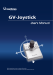
GV-Keyboard
User's Manual V2.0
Before attempting to connect or operate this product,
please read these instructions carefully and save this manual for future use.
© 2007 GeoVision, Inc. All rights reserved.
Under the copyright laws, this manual may not be copied, in whole or in part,
without the written consent of GeoVision.
Every effort has been made to ensure that the information in this manual is
accurate. GeoVision is not responsible for printing or clerical errors.
GeoVision, Inc.
9F, No. 246, Sec. 1, Neihu Rd.,
Neihu District, Taipei, Taiwan
Tel: +886-2-8797-8377
Fax: +886-2-8797-8335
http://www.geovision.com.tw
Trademarks used in this manual: GeoVision, the GeoVision logo and GV
series products are trademarks of GeoVision, Inc. Windows and Windows XP
are registered trademarks of Microsoft Corporation.
June 2007
Table of Contents
Regulatory Notices ...................................................................................1
1.
2.
3.
Introduction .....................................................................................2
1.1
Packing List ............................................................................................................2
1.2
System Requirements ............................................................................................2
System Connections .......................................................................3
2.1
Rear Panel Overview..............................................................................................3
2.2
Connecting GV-Keyboard to One GV-System ........................................................4
2.3
Connecting GV-Keyboard to Multiple GV-Systems.................................................5
2.4
Wall Terminal Block.................................................................................................6
Installation .......................................................................................7
3.1
USB Driver..............................................................................................................7
3.2
GV-Keyboard Application........................................................................................9
3.2.1
Defining Eight Function Keys.......................................................................10
3.2.2
Printing Function Key Labels .......................................................................10
4.
ID & Password Settings in DVRs .................................................. 11
5.
Keyboard Overview.......................................................................12
6.
Programming and Operation.........................................................15
7.
On-Screen Display Menus ............................................................16
7.1
The OSD in Main System .....................................................................................16
7.2
The OSD in ViewLog ............................................................................................17
8.
Shortcut Key Conflict Test .............................................................18
9.
Troubleshooting ............................................................................19
10.
Specifications ................................................................................20
Regulatory Notices
Regulatory Notices
FCC Notice
This equipment has been tested and found to comply with the limits for a Class A digital
device, pursuant to part 15 of the FCC Rules. These limits are designed to provide reasonable
protection against harmful interference when the equipment is operated in a commercial
environment.
Class A
This equipment generates, uses, and can radiate radio frequency energy and, if not installed
and used in accordance with the instruction manual, may cause harmful interference to radio
communications. Operation of this equipment in a residential area is likely to cause harmful
interference in which case the user will be required to correct the interference at their own
expense.
CE Notice
This is a Class A product. In a domestic environment, this product may cause radio
interference in which case the user may be required to take adequate measures.
RoHS Compliance
The Restriction of Hazardous Substances (RoHS) Directive is to forbid the use of hazardous
materials of production. To meet the RoHS Directive requirements, this product is made to be
RoHS compliant.
WEEE Compliance
This product is subject to the Waste Electrical and Electronic Equipment (WEEE) Directive
and made compliant with the WEEE requirements.
1
1.
Introduction
The GV-Keyboard is used to program and operate GV-Systems. Through RS-485
configuration, it can control up to 16 additional GV-Systems.
RX
P1
F1
F2
TX
P2
P3
P4
F4
F3
F5
REC
REC STOP
1
ALL
P5
SCH
SCH STOP
Sp eed +
F6
F7
F8
1
2
3
4
5
6
7
8
9
Zoom
In
Focus
In
Auto
Focus
Home
Zoom
Out
Focus
Out
Auto
Preset
OK
Menu
Cancel
A- B
Sp eed
-
0
1.1 Packing List
•
GV-Keyboard x 1
•
Power Adaptor (AC Input 110-240V to DC Output 12V, 1A) x 1
•
USB Cable x 1
•
RJ-11 Cable x 1
•
RS-232 Cable x 1
•
Wall Terminal Block x 1
•
GV-Keyboard User’s Manual x 1
1.2 System Requirements
•
Windows 2000, XP or Vista
•
GV-System V7.0 or above
2
2
2.
System Connections
System Connections
2.1 Rear Panel Overview
Figure 1
No Name
Function
1
Joystick
Used for PTZ control.
2
DC 12V
Connects to the power adaptor.
3
USB Port
Connects to GV-System.
4
RJ-11 Port (RS-485)
The RJ-11 port carries RS-485 signals. Through the wall
terminal block, it can connect up to 16 additional
GV-Systems.
5
Terminal Resistance
Used in the last daisy-chained GV-System.
6
RS-232
Connects to GV-System.
7
Reset
Resets the Keyboard when it does not respond to
commands.
3
2.2 Connecting GV-Keyboard to One GV-System
There are three ways to connect the Keyboard to one GV-System by:
1)
USB Port,
2)
RJ-11 Port (DC power required) , or
3)
RS-232 Port (DC power required)
GV-System
GV-Keyboard
Figure 2
*
4
USB cable, and RJ-11(RS-485) cable are supplied with the GV-Keyboard.
2
System Connections
2.3 Connecting GV-Keyboard to Multiple GV-Systems
To connect the Keyboard to up to 16 additional GV-Systems within 600 meters, use the RJ-11
Port, and plug in the power adapter.
Connects to PC's
Power Supply
RS-485+
RS-485-
GV-NET Card **
RS-232 (COM port)
GV-System 1
Wall Terminal
Block *
RJ-11 Cable *
Connects to PC's
Power Supply
RS-485+
RS-485-
GV-NET Card **
GV-Keyboard
RS-232 (COM port)
GV-System 16
Figure 3
*
The RJ-11 cable and Wall Terminal Block are supplied with the GV-Keyboard.
**
The GV-NET card can be replaced with other GV products, such as GV-NET, GV-NET/IO
card, GV-Hub and GV-COM.
5
2.4 Wall Terminal Block
1
6
Figure 4
Note:
When you are using the wall terminal block for connection, the RS-485 + and
RS-485 - cables should be attached to the terminal screws Pin 4 and Pin 3 respectively.
6
3
3.
Installation
Installation
3.1 USB Driver
If you use the USB port to connect the Keyboard to the GV-System, it is necessary to install
the USB driver. After you use the USB cable to connect the Keyboard to the GV-System, the
Found New Hardware Wizard will automatically detect the device. Ignore the Wizard and
follow these steps to install the driver:
1.
Insert the Software CD. It will run automatically and a window pops up.
Figure 5
2.
Select Install or Remove GV-Series Driver, and then click Install Geovision USB
Devices Driver. This dialog box appears.
Figure 6
7
3.
Click Install to install the driver. When the installation is complete, this message will
appear: Install done!
4.
Click Exit to close the dialog box.
5.
To verify that the driver is installed correctly, go to Windows Device Manager. In the Ports
(COM & LPT) field, you should see the entry for Prolific USB-to-Serial Bridge.
Figure 7
Note:
Remember the COM port showing in the Prolific USB-to Serial Bridge entry. It
indicates the port number that the Keyboard is using.
8
3
Installation
3.2 GV-Keyboard Application
When using the GV-Keyboard to control the GV-System, you need to run the following
program in the background.
1.
Run mcamctrl.exe from the GV-System folder.
Figure 8
2.
The Keyboard & Joystick controller dialog box appears.
Figure 9
The controls in the Keyboard & Joystick controller dialog box:
Name
Description
DVR ID
Selects the desired DVR ID for connection.
DVR Name
Gives the login DVR a descriptive name.
Startup type
Selects Manual or Automatic to run the controller at next startup.
PTZ Speed
Adjusts PTZ speed.
Port 1-4
Selects the port connecting to the Keyboard. Find the port number the
Keyboard is using in the Prolific USB-to-Serial Bridge entry. See 3.1
USB Driver.
►
Starts the service.
■
Stops the service.
F1 - F8
Defines eight function keys on the Keyboard to control output
modules, display layout, PTZs, and cameras.
Print Icon
Prints out a label for the eight function keys.
9
3.2.1
Defining Eight Function Keys
F1 - F8 options allow you to assign these features to the eight function keys on the Keyboard:
z
Output Control
z
Display Layout
z
PTZ Preset Go
z
PTZ Auto
z
Camera Select
z
Start/Stop Camera Scan
Note:
For the PTZ Preset Go and PTZ Auto functions, you must map the PTZ camera first
in Main System.
Figure 10
3.2.2
Printing Function Key Labels
The Print Memo option allows you to print out the labels for the eight function keys (F1 - F8)
so that you can paste them on the Keyboard for instant reference.
1.
Click the Printer icon. This displays the Printer Memo dialog box.
2.
Under every field from F1 to F8, type the information that you want to print on the labels.
The words you type will also appear on Preview fields for print preview.
3.
Click Print.
Figure 11
10
4
4.
ID & Password Settings in DVRs
ID & Password Settings in DVRs
For the Keyboard operation, you must export IDs and Passwords from GV-Systems first. Note
the IDs and passwords can be ONLY composed of digits.
1.
Click the Configure button, and select Password Setup. This displays the Password
Setup dialog box.
Figure 12
2.
Select a user from the user list, and then check Export this ID for IR Remote Control
(GV-Keyboard). This allows the export of its ID and Password.
When logging in the GV-System, you will see the exported ID in the ID drop-down list of the
Login dialog box.
11
5.
Keyboard Overview
Figure 13
z
Section A
☼
Yellow POWER LED
RX
Red RX LED (Receive)
TX
Green TX LED (Transmit)
P1
Changes DVR ID
P2
Configures the Keyboard parameters, including password, key
beep and auto-lock period
P3
Displays the firmwave version
P4-5
Reserved for future features
Locks the Keyboard
F1-8
12
Function keys
5
z
Keyboard Overview
Section B
Launches Multicam Surveillance System (Main System)
Launches ViewLog
Turns full screen view on/off
Switches the screen divisions
Turns the sound on/off
Plays next events automatically
Starts/Stops recording
Starts/Stops the scheduled recording
Goes to previous event
Goes to next event
Plays/Pauses a video event
Rewinds/Pauses a video event
Moves one frame back
Moves one frame forward
Stops a video event
Sets the starting and ending frames for auto playing
Increases playback speed
Decreases playback speed
Switches to previous screen
13
Switches to next screen
Numeric buttons
Enters the login password; Selects a specific camera; Changes
the Time Setting in ViewLog
z
Section C
Zooms in the display image of PTZ camera in Main System;
Zooms in the display image in ViewLog
Zooms out the display image of PTZ camera in Main System;
Zooms out the display image in ViewLog
Increases the focus of PTZ camera in Main System
Decreases the focus of PTZ camera in Main System
Auto Focus
Sets the PTZ camera for auto mode
Moves the PTZ camera to the default position
Moves the PTZ camera to a preset location
Calls up the Login dialog box; Enters the settings; Opens the OSD
menu
Closes the OSD menu; Returns to the previous menu; Calls up the
menu to exit Main System or ViewLog
PTZ control; Navigates the display image in ViewLog; Navigates
the OSD menu; Changes the Time Setting in ViewLog
14
6
6.
Programming and Operation
Programming and Operation
Function
Procedure
Getting started
Press any key, and enter a password.
(The default password is 0000.)
Launching Main
1.
Press
System
2.
When the message "Multicam System-Please Login!" appears
.
on the screen, press
Launching ViewLog
to open the Login dialog box.
3.
Select a valid ID, enter a password, and press
1.
Press
2.
When the Privilege Confirmation dialog box appears, select a
.
.
valid ID, enter a password, and press
Changing DVR ID
Press P1, and enter a two-digit DVR ID.
Changing password
1.
Press P2, enter a password, and press
.
to browse LCD
displays.
2.
When "Password Change" appears, press
and enter a
four-digit password.
Disabling/Enabling
1.
key beep
Press P2, enter a password, and press
to browse LCD
displays.
2.
When "Audio Setting" appears, press
and press
to enable/disable the key beep.
Setting auto-lock
1.
period
Press P2, enter a password, and press
to browse LCD
displays.
2.
When "Auto Time Lock" appears, press
and enter an idle
period after which the Keyboard is automatically locked.
* The Keyboard can be used only if the correct password is
entered.
Setting A to B frame
1.
for auto-playing
Press
. The message "A To B Mode (Set A)" appears on
the screen.
2.
Press
again. The message "A To B Mode (Set B)"
appears. ViewLog starts playing the set frames A to B
repeatedly.
* To stop the playing, press
. The message "A To B
Mode (Cancelled)” will appear.
15
7.
On-Screen Display Menus
In Main System and Viewlog modes, you can press
to call up the on-screen display
(OSD) menus.
7.1 The OSD in Main System
Figure 14
The OSD menus in Main System
Screen Division
Changes the screen divisions
Input Device
Displays all or several input module panels
Output Device
Forces output devices
PTZ Camera
Enables/Disables PTZ camera, Preset Go, Auto (Auto Pan), AF (Auto
Focus) and Hide PTZ Panel
Monitor
Starts/Stops all or several cameras for monitoring
Schedule
Enables/Disables the schedule
Camera Scan
Enables/Disables the rotation through screen divisions
Network
Enables/Disables remote applications, including Modem Server, TCP
Server, Multicast Server, Connect to VSM, Twin Server, WebCam Server
and Connect to Center V2
16
7
7.1.2
On-Screen Display Menu
Changing the Main System OSD Options
To change the Main System OSD options with the Keyboard, follow the steps below:
1.
Press the OK/Menu button to open the OSD (see Figure 14).
2.
Use the direction buttons to select a menu you want.
3.
Press the OK/Menu button to open the menu.
4.
Use the direction buttons to select a menu option, and then press the OK/Menu button
to change the setting.
OR
Simply press the OK/Menu button to enable or disable an option in the case of Schedule
and Camera Scan.
7.2 The OSD in ViewLog
Figure 15
The OSD menus in ViewLog
Video Event Search
1.
Press the
Locates a video event.
and
buttons to move back and forward on an OSD
time. (Month/Date/Year Hr.:Min.:Sec.)
2.
Use the numeric buttons to enter a desired time or press
and
to change the display time.
3.
Press the OK/Menu button to view the search result.
If the specified time can't be located, you will be prompted for previous or
next video event available.
View Mode
Changes the view modes, including Single View, Thumbnail View, Quad
View and Multi View.
7.2.1
Changing the ViewLog OSD options
To change the ViewLog OSD options with the Keyboard, follow the steps below:
1.
Press the OK/Menu button to open the OSD. See Figure 15.
2.
Use the direction buttons to select a menu you want.
3.
Press the OK/Menu button to open the menu.
4.
Use the direction buttons to select a menu option, and then press the OK/Menu button to
change the setting.
17
8.
Shortcut Key Conflict Test
This test checks whether the Keyboard keys are conflicting with certain shortcut keys of other
applications.
1.
Execute GvKeyTest.exe from the GV-System folder. This dialog box appears.
Figure 16
2.
Click the Test button. If there are shortcut key conflicts, a similar message box as below
appears.
Figure 17
3.
18
Disable the shortcut key settings of another application.
9
9.
Troubleshooting
Troubleshooting
Problem
Checklist
No power to Keyboard
¾
Check USB connection.
¾
If you are using the RS-232 port or RS-485 port for
connection, make sure to connect the power adaptor.
Keyboard has power but
¾
Check that Keyboard is not locked. See “Getting started”,
6. Programming and Operation on page 15.
does not respond to any
buttons pressed
Keyboard responds to
¾
some, but not all buttons
Message "Connect fail "
Check if Keyboard keys are conflicting with other
applications. See 8. Shortcut Key Conflict Test on page 18.
¾
displays on LCD
Verify that the selected ID in Mulitcam Controller is
consistent with the DVR ID. See “Changing DVR ID”,
6. Programming and Operation on page 15.
¾
Check that the COM port setting in Mulitcam Controller is
correct. See Step 5 of 3.1 USB Driver on page 8.
¾
If multiple GV-Systems are daisy-chained together,
(1)
check connections among GV-Systems, and
(2)
turn on Terminal Resistance to increase frequency
response.
¾
If you are using the wall terminal block, check
(1)
terminal screws are not loose,
(2)
the RS-485 + and RS-485 - cables are attached to the
appropriate terminal screws. See 2.4 Wall Terminal
Block on page 6.
Keyboard LEDs not
¾
Yellow POWER LED: check the power source.
visible
¾
When you press any key, you can't see the RX or TX LEDs.
¾
Red RX LED: check the connection between Keyboard and
GV-System.
¾
Green TX LED: check if Keyboard is malfunctioning.
19
10.
Specifications
Output
RS-232 to PC
DB9 Female
USB
USB 1.1
Connects to GV-NET, GV-NET
RS-485+
card RS-485+, GV-Hub or
GV-COM
RS-485Communication
Power
Environmental Conditions
Dimensions
Connects to GV-NET, GV-NET
card RS-485-, GV-Hub or GV-COM
RS-232
9,600 bps
RS-485
9,600 bps
DC IN
DC 12V 1A
RS-485
DC 12V
Operation temperature
0~50˚C
Humidity
5%~95% (non-condensing)
300 (W) x 45 (H) x 161 (D) mm
Note: The product does not support 64-bit Windows versions currently.
20