1
APS2 Documentation
Release 1.0
Blake Johnson, Colm Ryan, and Brian Donovan
November 19, 2015
Contents
1
Hardware Specifications
1.1 Detailed Specifications . .
1.2 Triggering . . . . . . . .
1.3 Communications Interface
1.4 Status LED’s . . . . . . .
.
.
.
.
.
.
.
.
.
.
.
.
.
.
.
.
.
.
.
.
.
.
.
.
.
.
.
.
.
.
.
.
.
.
.
.
.
.
.
.
.
.
.
.
.
.
.
.
.
.
.
.
.
.
.
.
.
.
.
.
.
.
.
.
.
.
.
.
.
.
.
.
.
.
.
.
.
.
.
.
.
.
.
.
.
.
.
.
.
.
.
.
.
.
.
.
.
.
.
.
.
.
.
.
.
.
.
.
.
.
.
.
.
.
.
.
.
.
.
.
.
.
.
.
.
.
.
.
.
.
.
.
.
.
.
.
.
.
.
.
.
.
.
.
.
.
.
.
.
.
.
.
.
.
.
.
.
.
.
.
3
3
3
5
5
Installation Guide
2.1 Hardware . . . . .
2.2 Software . . . . .
2.3 Networking Setup
2.4 Firmware Updates
.
.
.
.
.
.
.
.
.
.
.
.
.
.
.
.
.
.
.
.
.
.
.
.
.
.
.
.
.
.
.
.
.
.
.
.
.
.
.
.
.
.
.
.
.
.
.
.
.
.
.
.
.
.
.
.
.
.
.
.
.
.
.
.
.
.
.
.
.
.
.
.
.
.
.
.
.
.
.
.
.
.
.
.
.
.
.
.
.
.
.
.
.
.
.
.
.
.
.
.
.
.
.
.
.
.
.
.
.
.
.
.
.
.
.
.
.
.
.
.
.
.
.
.
.
.
.
.
.
.
.
.
.
.
.
.
.
.
.
.
.
.
.
.
.
.
.
.
.
.
.
.
.
.
.
.
.
.
.
.
7
7
7
9
9
3
Pulse Sequencing
3.1 Background . . . . . . . . . . . . . . . . . . . . . . . . . . . . . . . . . . . . . . . . . . . . . . . .
3.2 Sequencer Design . . . . . . . . . . . . . . . . . . . . . . . . . . . . . . . . . . . . . . . . . . . .
13
13
13
4
Trigger Distribution Module
4.1 Base Functionality . . . . . . . . . . . . . . . . . . . . . . . . . . . . . . . . . . . . . . . . . . . .
4.2 Building Custom Firmware . . . . . . . . . . . . . . . . . . . . . . . . . . . . . . . . . . . . . . .
15
15
15
5
APS2 Instruction Set
5.1 Abstract Instructions . . . . . . . . . . . . . . . . . . . . . . . . . . . . . . . . . . . . . . . . . . .
5.2 Concrete Instructions . . . . . . . . . . . . . . . . . . . . . . . . . . . . . . . . . . . . . . . . . . .
5.3 Example Sequences . . . . . . . . . . . . . . . . . . . . . . . . . . . . . . . . . . . . . . . . . . .
17
17
18
21
6
Formats
6.1 Waveforms . . . . . . . . . . . . . . . . . . . . . . . . . . . . . . . . . . . . . . . . . . . . . . . .
6.2 Instructions . . . . . . . . . . . . . . . . . . . . . . . . . . . . . . . . . . . . . . . . . . . . . . . .
6.3 Sequence Files . . . . . . . . . . . . . . . . . . . . . . . . . . . . . . . . . . . . . . . . . . . . . .
23
23
23
23
7
API Reference
7.1 Enums . . . . . . . . . . . . . . . . . . . . . . . . . . . . . . . . . . . . . . . . . . . . . . . . . .
7.2 High-level methods . . . . . . . . . . . . . . . . . . . . . . . . . . . . . . . . . . . . . . . . . . . .
7.3 Low-level methods . . . . . . . . . . . . . . . . . . . . . . . . . . . . . . . . . . . . . . . . . . . .
25
25
25
28
8
Indices and tables
29
2
.
.
.
.
.
.
.
.
.
.
.
.
.
.
.
.
i
ii
APS2 Documentation, Release 1.0
This document serves as the user manual and programming guide for the Arbitrary Pulse Sequencer, version 2 (APS2).
Contents:
Contents
1
APS2 Documentation, Release 1.0
2
Contents
CHAPTER 1
Hardware Specifications
The BBN Arbitrary Pulse Sequencer 2 (APS2) is a modular system providing up to 18 channels of analog waveform
generation with a maximum output rate of 1.2 GS/s and 14-bits of vertical resolution. Each module in an APS2 system
provides two analog outputs, DC coupled into a fixed +/- 1V range, and four digital outputs (1.5 V) for triggering other
equipment. Each APS2 module has 1 GB of DDR3 SDRAM for waveform and sequence storage, which is enough for
over 64 million sequence instructions. A low-latency cache allows for fast access to 128K waveform samples. Each
module can be independently triggered for sophisticated waveform scenarios.
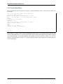
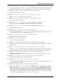
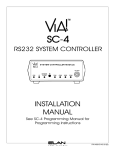
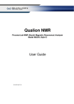
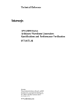
The digital and analog circuits have been carefully engineered to provide extremely low-noise analog performance,
resulting in a noise spectral density that is orders of magnitude lower than competing products, as shown in Noise
Comparison.
1.1 Detailed Specifications
Analog channels
Digital channels
Analog Jitter
Digital Jitter
Rise/fall time
Settling time
Trigger modes
Ext. trigger input
Reference input
Waveform cache
Sequence memory
Min instruction duration
Max instruction duration
Max loop repeats
two 14-bit 1.2 GS/s outputs per module
four 1.5V outputs per module
7.5ps RMS
5ps RMS
2ns
2ns to 10%, 10ns to 1%
Internal, external, system, or software triggering
1 V minimum into 50 Ω, 5 V maximum; triggered on rising edge
10 MHz sine or square, 1V to 3.3V peak to peak (+4 to +14 dBm)
128K samples
64M instructions
8 samples
8M samples (~7ms at 1.2GS/s)
65,536
1.2 Triggering
The APS2 supports four different types of triggers. The internal mode generates triggers on a programmable interval
between 6.66ns and 14s. The external mode listens for triggers on the front-panel SMA “trigger input” port. In this
mode, the APS2 is triggered on the rising edge of a 1-5V signal. The system trigger accepts triggers on the SATA
input port from the APS2 Trigger Distribution Module (TDM). Finally, the software mode allows the user to trigger
the APS2 via the host computer with the trigger() API method.
3
APS2 Documentation, Release 1.0
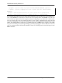
−90
II X6−1000M
BBN APS
Tek5014
−100
−110
−120
−130
−140
−150
−160 0
10
1
10
2
10
3
10
Frequency (Hz)
4
10
5
10
Fig. 1.1: Comparison of AWG output noise Output noise power versus frequency for the Tektronix AWG5014,
Innovative Integration X6-1000M, and BBN APS. The APS’s linear power supplies and low-noise output amplifier
lead to signficant improvements in the noise performance. The II X6 is significantly better than the Tek5014, but
suffers from resonances in the noise spectrum because it is in a host PC environment.
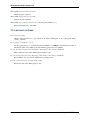
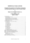
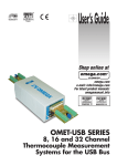
Fig. 1.2: BBN APS2 front panel The front panel of the APS has two analog outputs, 4 marker outputs, a trigger
input, two SATA ports, a 1 GigE port, a 10 MHz reference input and two status LEDs.
4
Chapter 1. Hardware Specifications
APS2 Documentation, Release 1.0
1.3 Communications Interface
The APS2 communicates with a host PC via the UDP protocol over 1GigE. The current APS2 firmware requires a
fixed IPv4 address. Instructions for setting the APS2 IP address are contained in the Software section. Use of the
UDP protocol allows for a large-througput link from the host PC to the APS2; however, it does not natively support
error checking of the sent data. The libaps2 driver adds some error-checking and packet resending to UDP, but it is
recommended to not place too many network hops between the host PC and the APS2.
1.4 Status LED’s
The L1 and L2 LEDs provide status indicators for the communication (L1) and sequencing (L2) firmware components.
L1:
• green breathing - no ethernet connection;
• green blinks - receiving or transmitting an ethernet packet;
• red - fatal communication error. Power cycle the module to restore connectivity.
L2:
• dark - idle;
• solid green - playback enabled and outputing sequences;
• green breathing - playback enabled but no trigger received in the past 100ms;
• red - fatal cache controller error. Power cycle the module to restore playback functionality.
1.3. Communications Interface
5
APS2 Documentation, Release 1.0
6
Chapter 1. Hardware Specifications
CHAPTER 2
Installation Guide
2.1 Hardware
The BBN APS2 system contains one or more analog output modules and an advanced trigger module in an enclosure
that supplies power to each module. Up to 9 analog modules may be installed in a single 19” 8U enclosure, providing
18 analog output channels. Installing a new module only requires plugging it into a free slot of a powered-off system,
then connecting a SATA cable from the new APS module to the trigger module.
Each module in an APS2 system acts as an independent network endpoint. The modules communicate with a host
computer via a UDP interface over 1GigE. The APS2 will not negotiate down to 100Mb or 10Mb so ensure you have
an appropriate switch and patch cable. To ensure high-bandwidth throughput, it is important that the APS2 and the
host computer not be separated by too many network hops. If possible, locate the host and APS2 on a common switch
or router 1 .
While the APS can run in a standalone configuration, we recommend running with a 10 MHz (+7 dBm) external
reference (square wave or sine wave). This reference must be supplied at the corresponding front panel inputs before
powering on the system. Multiple devices can be synchronized by supplying an external trigger that is phase locked
to this same reference.
2.2 Software
In order to control the APS2, BBN provides a Windows shared library. You may download this driver from our APS2
source code repository (http://github.com/BBN-Q/libaps2). Click on ‘releases’ to find the latest binaries. We provide
MATLAB wrappers to this library, but the APS2 may be used with any software that can call a C-API DLL. To use
the MATLAB driver, simply add the path of the unzipped driver to your MATLAB path. The driver depends on
other shared libraries, for example HDF5 and the gcc libstdc++ from MinGW-w64. We include these DLL’s with the
Windows releases and they need be in the same folder as the driver to ensure they can by dynamically loaded with the
libaps2 driver 2 .
2.2.1 File List
The releases follow a directory structure that corresponds to the git repository.
• examples - Example sequence and waveform files
1
The APS2 use static self-assigned IP addresses and should ideally be behind the same router as the control computer.
There is the potential for conflicts with previously loaded DLL’s that are incompatible versions. For example, if you have loaded another driver
into Matlab that was built with a different version of MinGW-w64 or trying to load libaps2 into Julia which was built with a different version of
MinGW-w64. There is no easy solution to this problem on the Windows platform. Please contact BBN if you run into this situation.
2
7
APS2 Documentation, Release 1.0
– wfA.dat and wfB.dat - test waveform patterns for play_waveform.cpp as signed integers one sample per line:
* a full scale ramp;
* gaussian pulses from 256 samples down to 8 samples with 10ns gaps;
* square wave from 256 down to 8 samples with 10ns gaps;
* wfB.dat is negative wfA.dat.
– ramsey_unslipped.h5 - an 10 sequence Ramsey pattern with 40ns gausssian shaped pulses in a 40ns
delay - X90 - variable delay - X90m pattern with the delay stepping from 44 to
104 samples. All four markers are mirrored and act as blanking pulses around the analog pulses.
– ramsey_slipped.h5‘ - a similar Ramsey pattern but with the markers slipped by one sample to show
the marker resolution and jitter.
• src - the source code
– src/lib - the shared library. libaps2.h contains the public API definitions.
– src/matlab - Matlab bindings to libaps2
– src/julia - Julia bindings to libaps2
– src/util - test and utility command line programs. See below for description.
– src/C++ - C++ command line programs to play waveforms and sequences.
– src/wireshark - lua dissector for sniffing APS2 packets.
• build - compiled shared library and executable programs
– Shared library
* libaps2.dll - the main shared library
* load time dependencies for libaps2: libgcc_s_seh-1.dll, libhdf5-0.dll, libhdf5_cpp-0.dll,
libstdc++-6.dll, libwinpthread-1.dll, libszip-0.dll, zlib1.dll
– Command line programs
* play_waveform.exe - command line program to play a single waveform on the analog channels.
* play_sequence.exe - command line program to play a HDF5 sequence file.
– Command line utilities
* program.exe - update the firmwave. See Firmware Updates.
* flash.exe - update IP and MAC addresses and the boot chip configuration sequence.
* reset.exe - reset an APS2.
– Self-test programs
* test_comms.exe - tests the ethernet communications writing and reading
* test_DACs.exe - tests the analog output data integrity with a checksum at three points: leaving
the FPGA; arriving at the DAC; leaving the DAC.
2.2.2 Writing Sequences
The BBN APS2 has advanced sequencing capabilities. Fully taking advantage of these capabilities may require use
of higher-level languages which can be ‘compiled down’ into sequence instructions. BBN has produced one such
language, called Quantum Gate Language (QGL), as part of the PyQLab suite (http://github.com/BBN-Q/PyQLab).
8
Chapter 2. Installation Guide
APS2 Documentation, Release 1.0
We encourage end-users to explore using QGL for creating pulse sequences. You may also find the sequence file
export code to be a useful template when developing your own libraries. A detailed instruction format specification
can be found in the Concrete Instructions section.
2.3 Networking Setup
Once the APS2 has been powered on, the user must assign static IP addresses to each module. By default, the
APS2 modules will have addresses on the 192.168.2.X subnet (e.g. the leftmost module in the system will have the
address 192.168.2.2, and increase sequentially left-to-right). The enumerate() method in libaps2 may be used to
find APS2 modules on your current subnet. Another method, set_ip_addr() may be used to program new IP
addresses. Since the APS2 modules will respond to any valid packet on its port, we recommend placing the APS2
system on a private network, or behind a firewall.
The control computer must be on the same subnet as the APS2 to respond to returning packets. Most operating systems
allow multiple IP addresses to coexist on the same network card so the control computer must add a virtual IP on the
subnet.
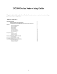
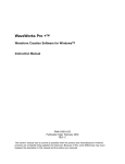
2.3.1 Windows
Under the Control Panel - Network and Internet - Network Connections click on the “Local Area Connection” and
then properties to change the adapter settings. Then set the properties of the TCP/IPv4 interface.
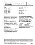
Then under the Advanced tab it will be possible to add additional IP addresses. Unfortunately, Windows does not
support multiple IP addresses with DHCP so a static address is required for the main network.
2.3.2 Linux
Temporary IP addresses can be obtained by adding additional ethernet interfaces:
sudo ifconfig eth0:0 192.168.2.1 netmask 255.255.255.0 up
A more permanent solution would involve editing the network interfaces file, e.g. /etc/network/interfaces.
2.3.3 OS X
In the System Preferences pane under Networking use the “Plus” button to add an interface.
2.4 Firmware Updates
BBN releases periodic firmware updates with bug-fixes and enhancements. These can be loaded onto the APS2
modules using the program executable:
./program
BBN AP2 Firmware Programming Executable
USAGE: program [options]
Options:
--help
--bitFile
--ipAddr
Print usage and exit.
Path to firmware bitfile.
IP address of unit to program (optional).
2.3. Networking Setup
9
APS2 Documentation, Release 1.0
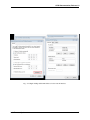
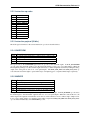
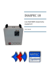
Fig. 2.1: Step 1 accessing the IPv4 settings for the network interface.
10
Chapter 2. Installation Guide
APS2 Documentation, Release 1.0
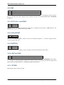
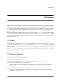
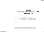
Fig. 2.2: Step 2 Adding addition IP addresses for the network interface.
2.4. Firmware Updates
11
APS2 Documentation, Release 1.0
--progMode
--logLevel
(optional) Where to program firmware DRAM/EPROM/BACKUP (optional).
(optional) Logging level level to print (optional; default=2/INFO).
Examples:
program --bitFile=/path/to/bitfile (all other options will be prompted for)
program --bitFile=/path/to/bitfile --ipAddr=192.168.2.2 --progMode=DRAM
The executable will prompt the user for ip address and programming mode. The APS2 can boot from multiple locations: volatile DRAM; non-volatile flash or if all else fails a master backup in flash. The DRAM storage takes only
a few seconds to program and is used for temporary booting for testing purposes. It will be lost on a power cycle.
Once you are happy there are no issues with the new bitfile you can program it to the flash memory so the module will
boot from the new firmware on a power cycle. This process involves erasing, writing and verifying and takes several
minutes. The backup firmware should only be programmed in the rare case BBN releases an update to the backup
image. Should something catastrophic happen during programming (unplugging the ethernet cable) the module may
drop to an extremely primitive firmware that will flash L1 and L2 in an alternating fashion. Should this happen contact
BBN for assistance.
12
Chapter 2. Installation Guide
CHAPTER 3
Pulse Sequencing
3.1 Background
Sequencing typically requires construction of a sequence table which defines the order in which waveforms are played
along with control-flow instructions. In existing commercial AWGs, these control-flow instructions are limited to
repeated waveforms (basic looping) and non-conditional goto statements to jump to other sections of the waveform
table. More recently, equipment manufacturers have added rudimentary conditional elements through event triggers to
conditionally jump to an address in the waveform table upon receipt of an external trigger. This capability introduces
branches into the sequence table. Equipment manufacturers have also expanded the memory re-use concept by subsequences which allow for jumping to sections of the waveform table and then returning to the jump point in a manner
similar to a subroutine or function call in a standard programming language.
These recent additions expand the number of sequence flow graphs that can be built with these primitives. However,
they are still limited in several ways. First, previous implementations have not allowed arbitrary combinations of
control-flow constructs. For instance, it may be diserable to have all control-flow instructions be conditional, so that,
for example, subsequence execution could depend on external input. Or it may be desireable to construct recursive
control-flow structures, i.e. nested subsequences should be possible. Second, event triggers are not sufficiently expressive to choose between branches of more than two paths. With wider, multi-bit input interfaces, one can construct
higher-order branches (e.g. with a 2-bit input you could have four choices).
In short, rather than having an instruction set that allows for a limited number of control-flow graphs, we wish to
expand the instruction set of AWGs to allow for fully arbitrary control flow structures.
3.2 Sequencer Design
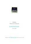
To achieve arbitrary control flow in an AWG, we adopt modern CPU design practice and separate the functions of control flow from instruction execution. An instruction decoder and scheduler broadcasts waveform and marker instructions to independent waveform and marker engines, while using control-flow instructions to decide which instruction
to read next. This asynchronous design allows for efficient representation of common AWG sequences. However, it
also requires reintroducing some sense of synchronization across the indepent waveform and marker engines. This
is achieved in two ways: SYNC instructions and write flags. The SYNC instruction ensures that all execution engines have finished any queued instructions before allowing sequencer execution to continue. The write flag allows
a sequence of waveform and marker instructions to be written to their respective execution engines simultaneously.
A waveform or marker instruction with its write flag low will be queued for its corresponding execution engine, but
instruction delivery is delayed until the decoder receives an instruction with the write flag high.
13
APS2 Documentation, Release 1.0
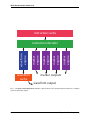
instruction cache
waveform
cache
marker
engine
marker
engine
marker
engine
marker
engine
waveform
engine
instruction decoder
marker outputs
waveform output
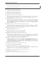
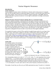
Fig. 3.1: Sequencer block diagram The APS has a single instruction decoder that dispatches instructions to multiple
waveform and marker engines.
14
Chapter 3. Pulse Sequencing
CHAPTER 4
Trigger Distribution Module
The trigger distribution module (TDM) provides a flexible mechanism for distributing triggers and pulse sequence
steering information across an APS2 crate. Since we expect our users to have diverse requirements for distributing
steering information, we have decided to deliver the TDM as a reconfigurable device with a basic firmware that will
satisfy certain needs.
4.1 Base Functionality
The base firmware delivered with the TDM will distribute signals captured on its front-panel interface to all APS2
modules connected by SATA cables. Port T8 is used as a ‘valid’ signal to indicate that data is ready to capture on T1T7. On the rising of a signal on T8, the signals on T1-T7 are captured into a 7-bit trigger word which is immediately
distributed across the APS2 crate. Each of the trigger ports T1-T8 drives a comparator with a programmable threshold.
The base firmware fixes this threshold at 0.8V.
4.2 Building Custom Firmware
The TDM firmware source may be found here: https://github.com/BBN-Q/APS2-TDM
To get starting creating your own APS2 TDM firmware, you need a copy of Xilinx Vivado 2015.1 (the free Webpack
edition is sufficient). Note that there are more recent versions of Vivado, but that the firmware source refers to specific
versions of Xilinx IP cores, and it may be necessary to convert these for use with later Vivado versions. The APS2
TDM firmware relies upon one not-free Xilinx IP Core, the Tri-Mode Ethernet Media Access Controller, or TEMAC:
http://www.xilinx.com/products/intellectual-property/temac.html
You can build the firmware without buying a TEMAC license, but the controller will stop functioning ~8 hours after
loading the image, and you will be forced to power cycle the APS2 TDM to continue. We recommend purchasing a
project license for the Xilinx TEMAC if you plan to build your own TDM firmware.
Refer to the README in the APS2-TDM firmware source for instructions on creating a Vivado project.
15
APS2 Documentation, Release 1.0
16
Chapter 4. Trigger Distribution Module
CHAPTER 5
APS2 Instruction Set
5.1 Abstract Instructions
Arbitrary control flow requires three concepts: sequences, loops (repetition) and conditional execution. We add to this
set the concept of subroutines because of their value in structured programming and memory re-use.
The BBN APS2 has two memories: a waveform memory and an instruction memory. These memories are accessed
via an intermediate caching mechanism to provide low-latency access to nearby sections of memory. In addition,
the APS has four other resources available for managing control flow: a repeat counter, an instruction counter, a
stack, and a comparison register. The instruction counter points to the current address in instruction memory. The
APS2 sequence controller reads and executes operations in instruction memory at the instruction pointer. Unless
the instruction specifies otherwise, by default the controller increments the instruction pointer upon executing each
instruction. The available abstract instructions are:
SYNC
WAIT
WAVEFORM address N
MARKER channel state N
LOAD_REPEAT count
REPEAT address
CMP operator N
GOTO address
CALL address
RETURN
PREFETCH address
We explain each of these instructions below.
SYNC—Halts instruction dispatch until waveform and marker engines have executed all queued instructions. The
write flag should be set to broadcast this instruction.
WAIT—Indicates that waveform and marker engines should wait for a trigger before continuing. The write flag should
be set to broadcast this instruction.
WAVEFORM—Indicates that the APS should play back length N data points starting at the given waveform memory
address. An additional flag marks the waveform as a time-amplitude variant, which outputs data at a fixed address for
N counts.
17
APS2 Documentation, Release 1.0
MARKER—Indicates the APS should hold marker channel in state (0 or 1) for N samples.
LOAD_REPEAT—Loads the given value into the repeat counter.
REPEAT—Decrements the repeat counter. If the resulting value is greater than zero, jumps to the given instruction
address by updating the instruction counter.
CMP—Compares the value of the comparison register to the mask N with any of these operators: =, ̸=, >, <. So,
(CMP ̸= 0) would be true if the comparison register contains any value other than zero.
GOTO—Jumps to the given address by updating the instruction counter.
CALL—Pushes the current instruction and repeat counters onto the stack, then jumps to the given address by updating
the instruction counter.
RETURN—Moves (pops) the top values on the stack to the instruction and repeat counters, jumping back to the most
recent CALL instruction.
PREFETCH—Flushes the waveform caches and refills starting at the currently requested address.
These instructions easily facilitate two kinds of looping: iteration and while loops. The former is achieved through
use of LOAD to set the value of the repeat counter, followed by the loop body, and terminated by REPEAT to jump
back to the beginning of the loop. The latter is achieved by a conditional GOTO followed by the loop body, where the
address of the GOTO is set to the end of the loop body.
Subroutines are implemented with the CALL and RETURN instructions. The address of a CALL instruction can
indicate the first instruction in instruction memory of a subroutine. The subroutine may have multiple exit points, all
of which are marked by a RETURN instruction.
Conditional execution is directly supported by the GOTO, CALL, and RETURN instructions. When these instructions
are preceeded by a CMP instruction, their execution depends on the comparison resulted. Consequently, the stated
instruction set is sufficient for arbitrary control flow.
Finally, filling the waveform cache is time consuming, requiring several hundred microseconds. Therefore, the
PREFETCH instruction allows one to schedule this costly operation during “dead time” in an experiment, e.g. immediately prior to instructions that wait for a trigger.
5.2 Concrete Instructions
The APS2 uses a 64-bit instruction format, divided into header (bits 63-56), and payload (bits 55-0). The format of
the payload depends on instruction op code.
5.2.1 Instruction header (8-bits)
Bit(s)
7-4
3-2
1
0
Description
op code
engine select (0-3)
reserved
write flag
The op code determines the instruction type. For MARKER instructions, the ‘engine select’ field chooses the output
channel of the instruction. The write flag is used to indicate the final instruction in a group of WAVEFORM and
MARKER instructions to be sent simultaneously to their respective execution engines.
18
Chapter 5. APS2 Instruction Set
APS2 Documentation, Release 1.0
5.2.2 Instruction op codes
Code
0x0
0x1
0x2
0x3
0x4
0x5
0x6
0x7
0x8
0x9
0xA
instruction
WAVEFORM
MARKER
WAIT
LOAD_REPEAT
REPEAT
CMP
GOTO
CALL
RETURN
SYNC
PREFETCH
5.2.3 Instruction payload (56-bits)
The 56-bit payload formats for the various instruction op codes are described below.
5.2.4 WAVEFORM
Bit(s)
47-46
45
44-24
23-0
Description
op code (0 = play waveform, 1 = wait for trig, 2 = wait for sync)
T/A pair flag
count
address
The top two bits of the WAVEFORM payload are an op code for the waveform engine. A PLAY_WAVEFORM
op code causes the waveform engine to play the waveform starting at address for count quad-samples. When the
time/amplitude pair flag is set, the waveform engine will create a constant- amplitude waveform by holding the analog
output at the value given at address for count quad-samples. The WAIT_FOR_TRIG and WAIT_FOR_SYNC op
codes direct the waveform engine to pause until receipt of an input trigger or a sequence SYNC input, respectively.
5.2.5 MARKER
Bit(s)
47-46
45-37
36-33
32
31-0
Description
op code (0 = play marker, 1 = wait for trig, 2 = wait for sync)
reserved
transition word
state
count (firmwave versions 2.5-2.33 support only 20 bit count)
The top two bits of the MARKER payload are an op code for the marker engine. A PLAY_MARKER op code causes
the marker engine to hold the marker output in value state for count quad-samples. When the count reaches zero, the
marker engine will output the 4-bit transition word. One use of this transition word is to achieve single- sample resolution on a low-to-high or high-to-low transition of the marker output. The WAIT_FOR_TRIG and WAIT_FOR_SYNC
op codes function identically to the WAVEFORM op codes.
5.2. Concrete Instructions
19
APS2 Documentation, Release 1.0
5.2.6 CMP
Bit(s)
9-8
7-0
Description
cmp code (0 = equal, 1 = not equal, 2 = greater than, 3 = less than)
mask
The CMP operation compares the current value of the 8-bit comparison register to mask using the operator given by
the cmp code. The result of this comparison effects conditional execution of following GOTO, CALL, and RETURN
instructions.
5.2.7 GOTO, CALL, and REPEAT
Bit(s)
25-0
Description
address
Jumps to address. For GOTO and CALL, the jump may be conditional if proceeded by a CMP instruction. For
REPEAT, the jump is conditioned on the repeat counter.
5.2.8 LOAD_REPEAT
Bit(s)
15-0
Description
repeat count
The repeat count gives the number of times a section of code should be repeated, i.e. to execute a sequence N times,
one uses a repeat count of N-1.
5.2.9 PREFETCH
Bit(s)
23-0
Description
address
Refills the waveform cache starting at address. Sequencer execution halts until the cache is filled.
5.2.10 WAIT and SYNC
Bit(s)
47-46
Description
op code (0 = play waveform/marker, 1 = wait for trig, 2 = wait for sync)
The payloads for the WAIT and SYNC instructions must also be valid WAVEFORM and MARKER payloads. Therefore, in addition to indicating WAIT or SYNC in the instruction header, the instruction type must also appear in the
payload. The write flag should be set to immediately dispatch this instruction.
5.2.11 RETURN
This instruction ignores all payload data.
20
Chapter 5. APS2 Instruction Set
APS2 Documentation, Release 1.0
5.3 Example Sequences
5.3.1 Ramsey
To give a concrete example of construction of a standard QIP experiment in the APS2 format, consider a Ramsey
experiment consisting of two 𝜋/2-pulses separated by a variable delay. If the waveform memory has a null-pulse at
offset 0x00 and a 16-sample 𝜋/2-pulse at offset 0x01, then the Ramsey sequence might in abstract format would look
like:
SYNC
WAIT
WAVEFORM 0x01 4
WAVEFORM T/A 0x00 10
WAVEFORM 0x01 4
SYNC
WAIT
WAVEFORM 0x01 4
WAVEFORM T/A 0x00 20
WAVEFORM 0x01 4
SYNC
WAIT
WAVEFORM 0x01 4
WAVEFORM T/A 0x00 30
WAVEFORM 0x01 4
.
.
.
GOTO 0x00
The {SYNC, WAIT} sequences demarcate separate Ramsey delay experiments, where the SYNC command ensures
that there is no residual data in any execution engine before continuing, and the WAIT command indicates to wait for
a trigger. The GOTO command at the end of the sequence is crucial to ensure that the instruction decoder doesn’t “fall
off” into garbage data at the end of instruction memory.
5.3.2 CPMG
The Carr-Purcell-Meiboom-Gill pulse sequence uses a repeated delay-𝜋-delay sequence to refocus spins in a fluctuating environment. For this sequence one could use a waveform library with three entries: a null pulse at offset 0x00, a
16-sample 𝜋/2-pulse at offset 0x01, and a 16-sample 𝜋-pulse at offset 0x05. Note that offsets are also written in terms
of quad-samples, so the memory address range of the first 𝜋/2 pulse is [0x01,0x04]. Then a CPMG sequence with 10
delay-𝜋-delay blocks might be programmed as:
SYNC
WAIT
WAVEFORM 0x01 4
LOAD_REPEAT 9
WAVEFORM T/A 0x00 25
WAVEFORM 0x05 4
WAVEFORM T/A 0x00 25
REPEAT
WAVEFORM 0x01 4
GOTO 0x00
Note that we load a repeat count of 9 in order to loop the block 10 times.
5.3. Example Sequences
21
APS2 Documentation, Release 1.0
5.3.3 Active Qubit Reset
Here we dynamically steer the sequence in response to a qubit measurment in order to actively drive the qubit to the
ground state:
GOTO 0x06 # jump over 'Reset' method definition
# start of 'Reset' method
WAIT # wait for qubit measurement data to arrive
CMP = 0 # if the qubit is in the ground state, return
RETURN
# otherwise, do a pi pulse
WAVEFORM 0x05 4
GOTO 0x01 # go back to the beginning of 'Reset'
# end of 'Reset' method
SYNC
CALL 0x01 # call 'Reset'
# qubit is reset, do something...
.
.
.
GOTO 0x00
In this example, we define a ‘Reset’ method for flipping the qubit state if it is not currently in the ground state. The
method is defined in instructions 1-5 of the instruction table. We preceed the method definition with a GOTO command
to unconditionally jump over the method definition. The structure of the ‘Reset’ method is a while loop: it only exits
when the comparison register is equal to zero. We assume that this register’s value is updated to the current qubit state
on every input trigger.
22
Chapter 5. APS2 Instruction Set
CHAPTER 6
Formats
6.1 Waveforms
Stored as arrays of signed 16-bit integers.
6.2 Instructions
Stored as arrays of unsigned 64-bit integers, with the instruction header in the 8 most signficant bits.
6.3 Sequence Files
HDF5 container for waveform and instruction data. The structure of this HDF5 file is as follows:
/version - attribute containing version information for the container structure
/chan_1/instructions - uint64 vector of instruction data
/chan_1/waveforms - int16 vector of waveform data
/chan_2/waveforms - int16 vector of waveform data
23
APS2 Documentation, Release 1.0
24
Chapter 6. Formats
CHAPTER 7
API Reference
BBN provides a C-API shared library (libaps2) for communicating with the APS2, as well as MATLAB and Julia
wrappers for the driver. We follow language conventions for index arguments, so channel arguments in the C-API are
zero- indexed, while in MATLAB and Julia they are one-indexed. Most of the C-API methods require a device serial
(an IP address) as the first argument. In MATLAB and Julia, the serial is stored in a device object and helper functions
inject it as necessary.
Before calling a device specific API the device must be connected by calling connect_APS. This sets up the ethernet
interface. Unloading the shared library without disconnecting all APS2s may cause a crash as the library unloading
order is uncontrolled. In addition, after every APS2 reset init_APS must be called once to properly setup the DAC
timing and cache- controller.
7.1 Enums
Nearly all the library calls return an APS2_STATUS enum. If there are no errors then this will be APS2_OK. Otherwise a more detailed description of the error an be obtained from get_error_msg. See the Matlab and Julia
drivers for examples of how to wrap each library call with error checking. The enum and descriptions can be found
APS2_errno.h.
There are also enums for the trigger mode, run mode, running status and logging level. These can be found in
APS2_enums.h or logger.h.
7.2 High-level methods
Getter calls return the value in the appropriate pointer.
const char* get_error_msg(APS2_STATUS)
Returns the null-terminated error message string associated with the APS2_STATUS code.
APS2_STATUS get_numDevices(unsigned int* numDevices)
This method sends out a broadcast packet to find all APS2’s on the local subnet and returns the number
of devices found.
APS2_STATUS get_deviceSerials(const char** deviceIPs)
Populates deviceIPs[] with C strings of APS2 IP addresses. The caller is responsible for sizing deviceIPs
appropriately. For example, in C++:
25
APS2 Documentation, Release 1.0
int numDevices = get_numDevices();
const char** serialBuffer = new const char*[numDevices];
get_deviceSerials(serialBuffer);
APS2_STATUS connect_APS(const char* deviceIP)
Connects to the APS2 at the given IP address.
APS2_STATUS disconnect_APS(const char* deviceIP)
Disconnects the APS2 at the given IP address.
APS2_STATUS reset(const char* deviceIP, int resetMode)
Resets the APS2 at the given IP address. The resetMode parameter can be used to do a hard reset from
non-volatile flash memory (resetMode = 0) or a soft reset from volatile DRAM (resetMode = 1) reset.
APS2_STATUS init_APS(const char* deviceIP, int force)
This method initializes the APS2 at the given IP address. This involves synchronizing and calibrating the
DAC clock timing and setting up the cache-controller. If force = 0, the driver will attempt to determine
if this procedure has already been run and return immediately. To force the driver to run the initialization
procedure, call with force = 1.
APS2_STATUS get_firmware_version(const char* deviceIP, uint32_t* version)
Returns the version number of the currently loaded firmware. The major version number is contained in
bits 15-8, while the minor version number is in bits 7-0. So, a returned value of 513 indicates version 2.1.
APS2_STATUS get_uptime(const char* deviceIP, double* upTime)
Returns the APS2 uptime in seconds.
APS2_STATUS get_mac_addr(const char* deviceIP, uint64_t* MAC)
Returns the MAC address of the APS2 at the given IP address.
APS2_STATUS set_ip_addr(const char* deviceIP, const char* ip_addr)
Sets the IP address of the APS2 currently at deviceIP to ip_addr. The IP address does not actually update
until reset() is called, or the device is power cycled. Note that if you change the IP and reset you will have
to disconnect and re-enumerate for the driver to pick up the new IP address.
APS2_STATUS set_sampleRate(const char* deviceIP, unsigned int rate)
Sets the output sampling rate of the APS2 to rate (in MHz). By default the APS2 initializes with a rate of
1200 MHz. The allow values for rate are: 1200, 600, 300, and 200. WARNING: the APS2 firmware has
not been tested with sampling rates other than the default of 1200. In particular, it is expected that DAC
synchronization will fail at other update rates.
APS2_STATUS get_sampleRate(const char* deviceIP, unsigned int* rate)
Returns the current APS2 sampling rate in MHz.
APS2_STATUS set_channel_offset(const char* deviceIP, int channel, float offset)
Sets the offset of channel to offset. Note that the APS2 offsets the channels by digitally shifting the
waveform values, so non-zero values of offset may cause clipping to occur.
APS2_STATUS get_channel_offset(const char* deviceIP, int channel, float* offset)
Returns the current offset value of channel.
APS2_STATUS set_channel_scale(const char* deviceIP, int channel, float scale)
26
Chapter 7. API Reference
APS2 Documentation, Release 1.0
Sets the scale parameter for channel to scale. This method will cause the currently loaded waveforms
(and all subsequently loaded ones) to be multiplied by scale. Values greater than 1 may cause clipping.
APS2_STATUS get_channel_scale(const char* deviceIP, int channel, float* scale)
Returns the scale parameter for channel.
APS2_STATUS set_channel_enabled(const char* deviceIP, int channel, int enabled)
Enables (enabled = 1) or disables (enabled = 0) channel.
APS2_STATUS get_channel_enabled(const char* deviceIP, int channel, int* enabled)
Returns the enabled state of channel.
APS2_STATUS set_trigger_source(const char* deviceIP, APS2_TRIGGER_SOURCE source)
Sets the trigger source to EXTERNAL, INTERNAL, SYSTEM, or SOFTWARE.
APS2_STATUS get_trigger_source(const char* deviceIP, APS2_TRIGGER_SOURCE* source)
Returns the current trigger source.
APS2_STATUS set_trigger_interval(const char* deviceIP, double interval)
Set the internal trigger interval to interval (in seconds). The internal trigger has a resolution of 3.333 ns
and a minimum interval of 6.67ns and maximum interval of 2^32+1 * 3.333 ns = 14.17s.
APS2_STATUS get_trigger_interval(const char* deviceIP, double* interval)
Returns the current internal trigger interval.
APS2_STATUS trigger(const char* deviceIP)
Sends a software trigger to the APS2.
APS2_STATUS set_waveform_float(const char* deviceIP, int channel, float* data, int numPts)
Uploads data to channel‘s waveform memory. numPts indicates the length of the data array. ±1 indicate
full-scale output.
APS2_STATUS set_waveform_int(const char* deviceIP, int channel, int16_t* data, int numPts)
Uploads data to channel‘s waveform memory. numPts indicates the length of the data array. Data should
contain 14-bit waveform data sign- extended int16’s. Bits 14-13 in each array element will be ignored.
APS2_STATUS set_markers(const char* deviceIP, int channel, uint8_t* data, int numPts)
FOR FUTURE USE ONLY Will add marker data in data to the currently loaded waveform on channel.
APS2_STATUS write_sequence(const char* deviceIP, uint64_t* data, uint32_t numWords)
Writes instruction sequence in data of length numWords.
APS2_STATUS load_sequence_file(const char* deviceIP, const char* seqFile)
Loads the APS2-structured HDF5 file given by the path seqFile. Be aware the backslash character must
be escaped (doubled) in C strings.
APS2_STATUS set_run_mode(const char* deviceIP, APS2_RUN_MODE mode)
Changes the APS2 run mode to sequence (RUN_SEQUENCE, the default), triggered waveform
(TRIG_WAVEFORM) or continuous loop waveform (CW_WAVEFORM) IMPORTANT NOTE The
run mode is not a state and the APS2 does not “remember” its current playback mode. The waveform
modes simply load a simple sequence to play a single waveform. In particular, uploading new sequence
or waveform data will cause the APS2 to return to ‘sequence’ mode. To use ‘waveform’ mode, call
set_run_mode only after calling set_waveform_float or set_waveform_int.
7.2. High-level methods
27
APS2 Documentation, Release 1.0
APS2_STATUS run(const char* deviceIP)
Enables the pulse sequencer.
APS2_STATUS stop(const char* deviceIP)
Disables the pulse sequencer.
APS2_STATUS get_runState(const char* deviceIP, APS2_RUN_STATE* state)
Returns the running state of the APS2.
7.3 Low-level methods
int set_log(char* logfile)
Directs logging information to logfile, which can be either a full file path, or one of the special strings
“stdout” or “stderr”.
int set_logging_level(TLogLevel level)
Sets the logging level to level (values between 0-8 logINFO to logDEBUG4). Determines the amount of
information written to the APS2 log file. The default logging level is 2 or logINFO.
int write_memory(const char* deviceIP, uint32_t addr, uint32_t* data, uint32_t numWords)
Write numWords of data to the APS2 memory starting at addr.
int read_memory(const char* deviceIP, uint32_t addr, uint32_t* data, uint32_t numWords)
Read numWords into data from the APS2 memory starting at addr.
int read_register(const char* deviceIP, uint32_t addr)
Returns the value of the APS2 register at addr.
28
Chapter 7. API Reference
CHAPTER 8
Indices and tables
• genindex
• modindex
• search
29