1
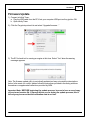
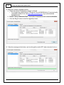
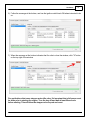
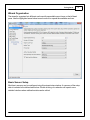
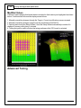
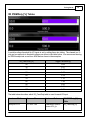
Instruction
Manual
Instruction Manual
Infinity V95
August 2014 Update Notes
STOP!
THIS PRODUCT HAS LEGAL RESTRICTIONS.
READ THIS BEFORE INSTALLING/USING!
THIS PRODUCT MAY BE USED SOLELY ON VEHICLES USED IN SANCTIONED COMPETITION WHICH MAY NEVER BE USED UPON A
PUBLIC ROAD OR HIGHWAY, UNLESS PERMITTED BY SPECIFIC REGULATORY EXEMPTION. (VISIT THE “EMISSIONS” PAGE AT HTTP://
WWW.SEMASAN.COM/EMISSIONS FOR STATE BY STATE DETAILS.)
IT IS THE RESPONSIBILITY OF THE INSTALLER AND/OR USER OF THIS PRODUCT TO ENSURE THAT IT IS USED IN COMPLIANCE WITH
ALL APPLICABLE LAWS AND REGULATIONS. IF THIS PRODUCT WAS PURCHASED IN ERROR, DO NOT INSTALL AND/OR USE IT. THE
PURCHASER MUST ARRANGE TO RETURN THE PRODUCT FOR A FULL REFUND.
THIS POLICY ONLY APPLIES TO INSTALLERS AND/OR USERS WHO ARE LOCATED IN THE UNITED STATES; HOWEVER CUSTOMERS
WHO RESIDE IN OTHER COUNTRIES SHOULD ACT IN ACCORDANCE WITH THEIR LOCAL LAWS AND REGULATIONS.
WARNING: This installation is not for the tuning novice! Use this system with EXTREME caution! The AEM
Infinity Programmable EMS allows for total flexibility in engine tuning. Misuse or improper tuning of this
product can destroy your engine! If you are not well versed in engine dynamics and the tuning of engine
management systems DO NOT attempt the installation. Refer the installation to an AEM-trained tuning
shop or call 800-423-0046 for technical assistance.
NOTE: All supplied AEM calibrations, Wizards and other tuning information are offered as potential
starting points only. IT IS THE RESPONSIBILITY OF THE ENGINE TUNER TO ULTIMATELY CONFIRM IF THE
CALIBRATION IS SAFE FOR ITS INTENDED USE. AEM holds no responsibility for any engine damage that
results from the misuse or mistuning of this product!
AEM Performance Electronics
AEM Performance Electronics, 2205 126th Street Unit A, Hawthorne, CA 90250
Phone: (310) 484-2322 Fax: (310) 484-0152
http://www.aemelectronics.com
Instruction Part Number: 10-71XX-Hardware
Document Build 1/6/2015
1
Infinity V95 August 2014 Update Notes
Introduction
Change Log V95 - August 2014 Minor Update
Firmware Changes and bug fixes:
Improved comms stability with high speed USB 3.0 ports.
Infinity Tuner Changes:
USB drivers now installed automatically.
Recent sessions feature added to the File menu.
New Application options feature added to File menu. See Application Options for more detail.
Prompt for save when shutting down - applies to sessions and layout files (selectable in
Application Options)
Layout preferences - No preference, load last, load specific or prompt user options available in
Application Options.
Save path for session and layout files now persists independently. Save paths can also be set
manually in Application Options.
Option to append firmware version to saved session and log files. Available in Application
Options.
Recent layouts feature added to the Layouts menu.
PC logging data is now written to disk periodically while logging. This minimizes the time
required to save to disk when PC logging is stopped. It also allows PC logged data to be
maintained in the event of a power interruption or comms error.
New legend toggle button added to plot control window.
Hot keys now available for certain types of plot control data manipulation.
Up/Page Up - Zoom in
Down/Page Down- Zoom out
Left - Pan left
Right - Pan right
Home - Bring you to the start of the log.
End - Brings you to the end of the log.
For Home and End, the current display range is kept. So if viewing 10 seconds worth of data,
Home will display the first 10 seconds while end will display the last 10 seconds.
Follow ECU function now available for 1D and 2D tables. See Follow ECU 11 for more detail.
Older pakgrp firmware files are now displayed but grayed out. This will help customers
understand they put the wrong file in the correct folder, so they can put the correct file in the
correct folder and proceed flashing the ECU.
Setup Wizard Changes:
© 2015 AEM Performance Electronics
Introduction
2
New left pane organization with expandable groupings. See Wizard Organization 8 for more
detail.
New Basic sensors section. See Basic Sensor Setup 8 for more detail.
New input function assignment section. See Input Function Assignments for more detail.
Left pane selection now highlighted when active and gray when not active.
Support added for Honda "T1" timing trigger.
Change Log - Known Bugs
Known Bug List
1. Connection error dialog is masked by reconnect dialog. This can be observed if the user
selects Connection > Connect to USB when the ECU is already connected AND subsequently
turns switched power off.
2. USB connection status message is not updated properly if the user selects Connection >
Connect to USB when the ECU is powered off AND subsequently turns switched power on.
3. Infinity Tuner will become unresponsive if user removes USB drive while Auto Save on connect
is in process.
4. If user selects Save As from the right click menu of Logging > USB Logging - Get Logs, then
cancels the action, the system will continue saving the first log in the list.
5. Format USB drive function does not validate if USB device is present or not.
6. Canceling the USB file save function during the file transfer process can result in inaccurate
file save status.
7. USB communication with Infinity Tuner may freeze for a few seconds when USB logging
conditions stop. If the USB drive includes a status LED, it may be blinking during this time
period.
8. Reassigning channels within existing controls or creating new controls during PC logging may
result in unexpected system behavior.
9. System Battery Volts channel can be misleading in the event of a gross wiring problem. If the
ECU is not wired correctly or if the main relay is not sending power to the ECUs 12V input
pins, the failsafe value could be displayed and indicating 13.850 volts when the actual voltage
to the ECU is 0 volts.
10. Cam 3/4 Noise Cancellation settings in Cam/Crank setup wizard page are listed but do not
apply to applications that don't support quad cam hardware inputs. Modifying the values
doesn't do anything in these cases.
© 2015 AEM Performance Electronics
3
Infinity V95 August 2014 Update Notes
Hardware
© 2015 AEM Performance Electronics
Hardware
4
Firmware Update
1) Connect to Infinity Tuner.
a. Plug the USB cable from the ECU into your computer USB port and key ignition ON.
b. Open Infinity Tuner.
2) Click the Target drop-down list and select “Upgrade firmware…”
3) The ECU should not be running an engine at this time. Select “Yes” when the warning
message appears.
Note: The firmware update utility is periodically updated and may not match the descriptions
below. In the event of a conflict, please follow the instructions provided in the dialog windows
themselves or supplemental instructions provided by AEM.
Important Note: BEFORE beginning the update process, be sure to have a saved copy
of your tuned session file. If a power failure occurs during the update process, this is
the only way to ensure that the calibration data is not lost.
© 2015 AEM Performance Electronics
5
Infinity V95 August 2014 Update Notes
4) Begin the Firmware Upgrade process.
a. Select the desired Configuration “Image” on the left.
i. If no images are present check C:\Program Files (x86)\AEM\Infinity Tuner\ and verify
.pakgrp file is there. If not, visit http://www.aeminfinity.com, log in, and download
appropriate file.
b. Ensure "Keep Calibration Data" check-box is marked to save current calibration.
c. Click the “Begin” button to start the upgrade process.
5) Follow the message at the bottom, and turn the ignition switch OFF when instructed to do so.
© 2015 AEM Performance Electronics
Hardware
6
6) Follow the message at the bottom, and turn the ignition switch back ON when instructed to do
so.
7) When the message at the bottom indicates that it’s safe to close the window, click "X” button
on the top right of the window.
For applications that use a stepper motor idle valve, it's important that a full power reset
be done prior to starting the engine. Turn the key off and wait at least 20 seconds
before starting. This will allow the stepper valve to park and reset.
© 2015 AEM Performance Electronics
7
Infinity V95 August 2014 Update Notes
A firmware update will erase the USB log channel list stored in the ECU memory. This
channel list will need to be reset before USB logging will function correctly. See Log
Menu for more info.
Troubleshooting:
If the process hangs at any point, wait at least one minute for it to continue. Some PCs
take longer to reconnect to to the ECU during this process. Some PCs may have other
processes running that affect the response time of the USB ports. If the process has
not continued as described above after one minute, do not cycle key power. Instead,
remove the USB cable from the PC, wait a few seconds then plug it back in. Often this
will force the OS to reset the port allowing the process to continue.
Tuning Guide
Basic Tuning
Wizard Basic Setup
© 2015 AEM Performance Electronics
Tuning Guide
8
Wizard Organization
The wizard is organized into different sections with expandable menu items on the left hand
pane. Use the highlighted arrow below in each section to expand the available sections.
Basic Sensor Setup
Most basic sensors can be configured using this wizard setup window. A summary of the setup
data is included in the table shown below. Double clicking on a selection will open a more
detailed interface where calibration data can be edited.
© 2015 AEM Performance Electronics
9
Infinity V95 August 2014 Update Notes
Several examples are shown below. The selections available in base session data may vary by
application.
© 2015 AEM Performance Electronics
Tuning Guide
TPS Cal Min [% ]:
This should be set to the manufacturer specifications.
TPS Cal Max must be > TPS Cal Min.
User entries that do not meet this criteria are not allowed.
Min value = -5.00, Max value = 105
TPS Cal Max [% ]:
This should be set to the manufacturer specifications.
TPS Cal Max must be > TPS Cal Min.
User entries that do not meet this criteria are not allowed.
Min value = -5.00, Max value = 105
© 2015 AEM Performance Electronics
10
11
Infinity V95 August 2014 Update Notes
TPS Min Volts:
This should be set to the manufacturer specifications.
TPS Max Volts must be > TPS Min Volts.
User entries that do not meet this criteria are not allowed.
Min value = 0, Max value = 5
Fuel Pressure Max Volts:
This should be set to the manufacturer specifications.
TPS Max Volts must be > TPS Min Volts
User entries that do not meet this criteria are not allowed.
Min value = 0, Max value = 5
Follow ECU
The follow ECU feature forces a small cell selection to "follow" the ECU as the table input data
changes. Using this feature combined with the hot key data manipulation options, allows the
tuner to quickly edit table data on the fly. The feature is available when connected to an ECU via
USB or when playing back logged data.
To turn on, with either a 1D/2DTable or 2D/3DGraph as the active control hit CTRL + F. When
activated, the follow will be set to all table type controls for the given item, and those controls will
have a "-- (Follow ECU)" in their title bar.
© 2015 AEM Performance Electronics
Tuning Guide
© 2015 AEM Performance Electronics
12
13
Infinity V95 August 2014 Update Notes
Modified Values
Calibration table changes that haven't been committed to flash memory are highlighted as shown
below. Conditions that will reset the display are as follows:
1. Manually committing changes through the Target > Commit modifications menu command
2. Manually committing changes using the hot key combination [Ctrl Shift C]
3. Opening and closing the Setup Wizard. Note the Setup Wizard automatically commits ALL
changes to memory every time it is closed.
4. Turning the ignition switch off when the tuning preference Key Off Commit is selected
Advanced Tuning
© 2015 AEM Performance Electronics
Tuning Guide
14
VR PWMDuty [%] Tables
A variable voltage threshold for VR inputs is set by editing these two tables. The channel is a %
duty and corresponds to threshold voltages as shown in the table below. We recommend leaving
the RPM breakpoints as set from AEM and as shown in the examples.
VR_Pwm Duty [%]
Trigger Threshold [V]
20
0.08
30
0.21
40
0.40
50
0.58
60
0.78
70
1.10
80
1.48
90
2.06
95
2.38
100
2.76
The table below describes which VR_PwmDuty table is used for each VR input.
Hardware Platform
Harness Pin
Hardware Ref.
VR PWMDuty [% ]
Table
Infinity-8/10/12
C1-45/C1-46
Crankshaft Position
Sensor VR+_In
VR_PwmDuty [%]
© 2015 AEM Performance Electronics
15
Infinity V95 August 2014 Update Notes
Hardware Platform
Infinity-8/10/12
Infinity-8/10/12
Infinity-8/10/12
Infinity-8/10/12
Infinity-8/10/12
Infinity-6/8H
Infinity-6/8H
Infinity-6/8H
Infinity-6/8H
Harness Pin
C1-47/C1-48
Hardware Ref.
Crankshaft Position
Sensor VR-_In
Camshaft Position
Sensor1 VR-_In
VR PWMDuty [% ]
Table
VR_PwmDuty [%]
C1-49/C1-50
Camshaft Position
Sensor1 VR+_In
VR+_In_2
VR1_PwmDuty [%]
C1-51/C1-52
VR-_In_2
VR-_In_3
VR1_PwmDuty [%
C2-25/C2-26
VR+_In_3
VR+_In_5
VR1_PwmDuty [%
C2-27/C2-28
VR-_In_5
VR-_In_4
VR1_PwmDuty [%
C1-17/C1-18
C1-19/C1-20
VR+_In_4
Crankshaft Position
Sensor VR+_In
Crankshaft Position
Sensor VR-_In
Camshaft Position
Sensor1 VR-_In
VR_PwmDuty [%]
VR_PwmDuty [%]
C1-54/C1-55
Camshaft Position
Sensor1 VR+_In
VR+_In_2
VR1_PwmDuty [%
C1-56/C1-57
VR-_In_2
VR-_In_3
VR1_PwmDuty [%
VR+_In_3
Cam/Crank Noise Cancellation Feature
Calculating Noise Cancellation Values for Specific Timing Patterns
Every timing pattern will have unique tooth widths for both the Cam and Crank signals.
Additionally, Engine Speed (RPM) determines the time duration of each tooth width. Therefore
© 2015 AEM Performance Electronics
Tuning Guide
16
there are several considerations to take into account when calculating the desired Noise
Cancellation values.
The shortest duration between edges is the first value to determine by examining the trigger
wheels or signal outputs from the Crank Position Sensor and Cam Position Sensor(s). This
means that either the shortest tooth or the shortest gap between teeth needs to be used in the
calculation (whichever is shorter in duration (degrees). What is important is the minimum time
between edge transitions, either high to low, or low to high within the entire trigger wheel. For a
60-2 even spaced trigger wheel, the minimum tooth duration is 6 degrees (360/60). However the
tooth is actually high for 3 degrees and low for 3 degrees. Therefore the useful value here is 3
degrees. This value will be used in Column D in the table below, which uses a 60-2 trigger wheel
as an example.
The second important variable specific to each engine is the maximum Engine Speed (RPM)
that the engine will spin to. This is because the duration of each degree of trigger wheel (in
microseconds) will be reduced as the engine spins to a higher RPM. The maximum desired
RPM needs to be used as the deciding factor, and can be seen in Cell A12 in the table below.
Use the table below to calculate the desired Noise Cancellation value for the Crank Position
Sensor for a 60-2 trigger wheel. The RPM values in Column A represent maximum desired RPM.
Assume for this example that you want to spin the engine to 9500 RPM. Therefore you will use
Row 12 to calculate the Noise Cancellation value.
From left to right, the RPM is used to calculate degrees per millisecond, the milliseconds per
degree, then microseconds between edge transitions, and finally Noise Cancellation values
based on 3.2us per increment. At 9500 RPM and 3 degrees between edge transitions, each
transition will happen in 52.6 microseconds. Therefore you can have a maximum Noise
Cancellation value of 16 (16 * 3.2us = 51.2us).
Another important consideration when determining Noise Cancellation values is that the values
calculated from the table above above assume a noise-free signal. More specifically, if noise
occurs at some location in between edge transitions, the effective tooth duration is split up by the
noise. If a single noise impulse occurs 1.5 degrees into a 3-degree tooth duration, then you will
effectively have two 1.5-degree teeth widths. Therefore the calculation above is only a guideline
and should not be used at the maximum limit. The actual Noise Cancellation value may have to
be 2-3 times smaller than the maximum allowed value to compensate for random noise injected
into the signal. To understand this idea more completely, refer back to the figures above.
© 2015 AEM Performance Electronics
17
Infinity V95 August 2014 Update Notes
CAN (AEMNet)
The CAN / AEMNet output is identical to the Series II datastream, with the exception of the
analog channels below.
CAN works, the ECU will broadcast the same CAN telemetry as a Series2 EMS. If working with
an AIM or RacePak dash, configure the dash as though it was receiving data from a Series2
EMS. No setup needed in the Infinity software, it's always broadcasting. Make sure you connect
the dash to the CAN_A pins (C1-31 and C1-32 on Infinity 8/10/12).
Since the Series2 default stream sent a bunch of spare ADCR_XX channels and the Infinity
similarly has a bunch of Analog_XX channels, the Infinity's 'Series2 Emulation' telemetry is
already broadcasting lots of Analog_XX volts signals that might be useful to view.
(these channels get broadcast on MessageID 0x01F0A001)
Series2 ADCR11 (bytes0-1) >> Infinity Analog09 Volts (pin C1-37) = Fuel Pressure volts
Series2 ADCR13 (bytes2-3) >> Infinity Analog10 Volts (pin C1-38)
Series2 ADCR14 (bytes4-5) >> Infinity Analog11 Volts (pin C1-39)
Series2 ADCR17 (bytes6-7) >> Infinity Analog12 Volts (pin C1-40)
(these channels get broadcast on MessageID 0x01F0A002)
Series2 ADCR18 (bytes0-1) >> Infinity Analog13 Volts (pin C2-18) = Oil Pressure volts
Series2 ADCR15 (bytes2-3) >> Infinity Analog14 Volts (pin C2-19)
Series2 ADCR16 (bytes4-5) >> Infinity Analog15 Volts (pin C2-20)
Series2 ADCR08 (bytes6-7) >> Infinity Analog16 Volts (pin C1-21)
Remember, these are broadcasting volts (0.0V - 5.0V) just like the Series2 did, so if you had an
AIM dash viewing fuel pressure or oil pressure, those channels might move to different 'ADCR'
assignments.
© 2015 AEM Performance Electronics