1
Installation Instructions for:
EMS P/N 30-1820
2004 Subaru Impreza WRX STI
and
EMS P/N 30-1821
2005-06 Subaru Impreza WRX STI
!
WARNING:
This installation is not for the tuning novice nor the PC illiterate!
Use this system with EXTREME caution! The AEM EMS System
allows for total flexibility in engine tuning. Misuse of this
product can destroy your engine! If you are not well versed in
engine dynamics and the tuning of management systems or are
not PC literate, please do not attempt the installation. Refer the
installation to a AEM trained tuning shop or call 800-423-0046
for technical assistance. You should also visit the AEM EMS
Tech Forum at http://www.aempower.com
NOTE: AEM holds no responsibility for any engine damage that
results from the misuse of this product!
This product is legal in California for racing vehicles only and should never be
used on public highways.
ADVANCED ENGINE MANAGEMENT INC.
2205 126th Street Unit A Hawthorne, CA. 90250
Phone: (310) 484-2322 Fax: (310) 484-0152
http://www.aempower.com
Instruction Part Number: 10-1820
2008 Advanced Engine Management, Inc.
Page 1 of 20
Congratulations! You have just purchased the finest Engine Management System for
your vehicle at any price.
The AEM Engine Management System (EMS) is the result of extensive development on
a wide variety of vehicles. Each system is engineered for a particular application. The
AEM EMS differs from all others in several ways. The EMS is a “stand-alone”, which
completely replaces the factory ECU and features unique plug and play technology.
There is no need to modify the factory wiring harness and in most cases the vehicle
may be returned to stock in a matter of minutes. The AEMPro software is configured to
work with the factory sensors and equipment, so there is no need for expensive or hard
to find sensors, making replacements and repairs as simple as with any stock vehicle.
For stock and slightly modified vehicles, the AEMPro software can be programmed with
base parameters, providing a solid starting point for beginner tuning. For more heavily
modified cars, the EMS has many spare inputs and outputs allowing the elimination of
add-on rev-limiters, boost controllers, nitrous controllers, fuel computers, etc. It also
includes a configurable onboard data logger that can record any 16 EMS parameters at
up to 250 samples per second. Every EMS comes with all functions installed and
activated; there is no need to purchase options or upgrades to unlock the full potential
of your unit.
Please visit the AEM EMS Tech Forum at http://www.aempower.com and register. We
always post the most current strategy release, PC Software and base calibrations
online. On the forum, you will find and share many helpful hints/tips to make your EMS
perform its best.
TUNING NOTES AND WARNING:
While the supplied startup calibration may be a good starting point and can save
considerable time and money, it will not replace the need to tune the EMS for your
specific application. AEM startup calibrations are not intended to be driven aggressively
before tuning. We strongly recommend that every EMS be tuned by someone who is
already familiar with the AEM software and has successfully tuned vehicles using an
AEM EMS. Most people make mistakes as part of the learning process; be warned that
using your vehicle as a learning platform can damage your engine, your vehicle, and
your EMS.
Page 2 of 20
Please read and understand these instructions BEFORE attempting to install your
EMS.
1) Removing the Stock Engine Control Unit
a) Access the stock Engine Control Unit (ECU). The location of the ECU on the
WRX is underneath the right side floorboard. A 10mm socket is required to
remove the kick panel that covers the stock ECU.
b) Carefully disconnect the wiring harness from the ECU. Avoid excessive stress or
pulling on the wires, as this may damage the wiring harness. Some factory ECUs
use a bolt to retain the factory connectors, and it must be removed before the
harness can be disconnected. There may be more than one connector, and they
must all be removed without damage to work properly with the AEM ECU. Do not
cut any of the wires in the factory wiring harness to remove them.
c) Remove the fasteners securing the ECU to the car body, and set them aside. Do
not destroy or discard the factory ECU, as it can be reinstalled easily for street
use and troubleshooting.
2) Installing the AEM Engine Management System.
a) Plug the factory wiring harness into the AEM EMS and position it so the wires are
not pulled tight or stressed in any manner. Secure the EMS with the provided
Velcro fasteners.
b) Plug the comms cable into the EMS and into the PC (not supplied).
c) Install the supplied AEM CD and open the AEMPro software.
d) Turn the ignition “on” but do not attempt to start the engine.
e) Go to: “ECU | Send New Calibration”. Upload the base calibration file (.cal) that
most closely matches the vehicle’s configuration to be tuned. Full details of the
test vehicle used to generate each map can be found in the “Notes” section in the
“Setup” window of the AEMPro software. The base maps can be found in the
Subaru folder located in: “My Computer | Local Disk (C:) | Program Files | AEM |
AEMPro | Startup Calibrations”
f) Calibrate the Electronic Throttle Control system by following the ETC Calibration
procedure - see page 8-9
g) Synchronize the ignition timing: Select the “Configure” drop down menu, then
“ECU Setup | Set Ignition”. Use a timing light and compare the physical engine
timing on cylinder #1 (front right cylinder on the STI) to the parameter “Ignition
Timing” displayed. Use the “Advance/Retard” buttons until the timing at the
engine matches the timing parameter displayed in the EMS.
3) Ready to begin tuning the vehicle.
a) Note: This calibration needs to be properly tuned and is not recommended for
street use. NEVER TUNE THE VEHICLE WHILE DRIVING.
Page 3 of 20
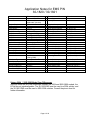
Application Notes for EMS P/N
30-1820 / 30-1821
Make:
Model:
Years Covered:
Engine Displacement:
Engine Configuration:
Firing Order:
N/A, S/C or T/C:
Load Sensor Type:
MAP Min:
MAP Max:
MAF Min:
MAF Max:
# Coils:
Ignition driver type:
How to hook up a CDI:
# Injectors:
Factory Injectors:
Factory Inj Resistors:
Injection Mode:
Knock Sensors used:
Lambda Sensors used:
Idle Motor Type:
Main Relay Control:
Crank Pickup Type:
Crank Teeth/Cycle:
Cam Pickup Type:
Cam Teeth/Cycle:
Subaru
Impreza WRX STI
2004
(30-1820 EMS)
2005-2006 (30-1821)
2.5L
Flat 4
1-3-2-4
Turbocharged
MAP or MAF
0.8V @ -14.7 PSIg
4.59V @ 23.8 PSIg
0.70V @ 0.0 Grams/Sec
4.84V @ 308 Grams/Sec
4, with internal igniters
0-5V Logic
Remove OEM coils
4 (Inj 1-4)
500 cc/min Saturated
No
Sequential
1
2 (OEM O2 sensors not
used by EMS)
None (Electronic Throttle)
Yes
Magnetic
36-2-2-2
Hall Effect
3
Transmissions Offered:
Trans Supported:
Drive Options:
Manual
Manual
AWD
Supplied Connectors:
Spare Injector Drivers:
Spare Injector Drivers:
Spare Injector Drivers:
Spare Injector Drivers:
Spare Coil Drivers:
Boost Solenoid:
EGT #1 Location:
EGT #2 Location:
EGT #3 Location:
EGT #4 Location:
Spare 0-5V Channels:
Spare Low Side Driver:
Spare Low Side Driver:
Spare Low Side Driver:
Spare Low Side Driver:
Check Engine Light:
Spare High Side Driver:
--Inj #5, pin A2
Inj #6, pin A3
Inj #7, pin A6
Inj #8, pin A7
--PW #2, pin A32
Pin C12
Pin D20
Pin D24
Pin D29
--Low Side #2, pin A13
Low Side #3, pin A12
Low Side #4, pin A14
Low Side #11, pin A24
Low Side #10, pin A17
High Side #2, pin A33
Spare Switch Input:
Spare Switch Input:
Spare Switch Input:
Spare Switch Input:
A/C Switch Input:
Switch #2, pin C9
Switch #3, pin A1
Switch #4, pin D11
Switch #5, pin D13
Switch #6, pin D16 / D17
Subaru 2004 / 2005-2006 Model Year Differences
Although there are very few differences between the 2004 and 2005-2006 models, the
ECUs are not interchangeable. The 30-1820 EMS must be used in a 2004 vehicle, and
the 30-1821 EMS must be used in 2005-2006 vehicles. Consult the pinout chart for
further information.
Page 4 of 20
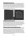
EMS Fuel Map, Boost Fuel Correct Table
The 30-1820/1821 maps provided utilize the “Boost Fuel Correct Table” to provide a 1:1
fuel compensation above atmospheric pressure. In the startup calibration, the “Boost
Fuel Correct Table” is configured to provide twice as much fuel when the manifold
pressure is twice as high; this should help simplify the tuning process for different boost
levels. Notice the values in the main “Fuel Map” do not change above 100 kPa (0 psi
boost), the fuel correction is being made by the “Boost Fuel Correct Table.” Note: the
“Boost Fuel Correct Table” must be adjusted if a different map sensor is installed (this is
because the load breakpoints change). The Boost Fuel Correct value should be 0 at
100 kPa, +100 at 200 kPa, +200 at 300 kPa, etc…
Subaru MAF sensor, Intake Air Temp sensor
The MAF (mass air flow) sensor can be removed to help decrease intake air restriction
as the base map uses the factory MAP sensor to determine engine load. Please be
aware that the IAT (intake air temperature) sensor is integrated into the factory MAF
sensor. If the factory MAF / IAT sensor is removed, you may wish to install an AEM IAT
Sensor Kit (P/N 30-2010), which includes a sensor, wire connector, and aluminum weldin bung. While the factory MAF sensor locates the IAT sensor upstream of the
turbocharger inlet, it may be preferable to install an IAT sensor downstream of the
intercooler to accurately measure charge temperatures.
EMS DC Stepper Motor control (Subaru Tumble Generator Valves)
There are two sets of Tumble Generator Valves (TGV) found on the intake manifold of
the STI. Each set of valves is driven by a DC stepper motor and has a 0-5V feedback
signal to monitor valve position. The Motor #1 and Motor #2 Target tables are used to
set the position of the valves; valve position can be controlled based on various
parameters such as throttle position, vehicle speed, engine RPM, or engine load. The
parameters “PR Press Voltage” and “Spare Temp Voltage” display the current position
of the valves. When these parameters are near 0 Volts, the valves are open and will
allow maximum air flow. When these parameters are near 5 Volts, the valves are closed
creating turbulence in the intake stream and restricting air flow. The valves are always
open in the AEM-supplied startup calibrations.
Page 5 of 20
WARNING: the EMS can be configured to control the left and right bank independently.
The engine will run very poorly if one set of TGVs is fully open while the other set is fully
closed, so please be sure that the Motor #1 and Motor #2 Target tables are both the
same.
EMS Variable Valve Control (Subaru AVCS)
The Variable Valve Control table in the EMS can be used to control the STI’s AVCS
system, which is used to change the airflow characteristics of the engine by advancing
the timing of the intake camshafts. When adjusting the Valve #1 and Valve #2 map,
please be aware that 55 represents minimum camshaft advance and 0 represents
maximum camshaft advance. The VVC settings provided in the AEM startup calibration
are the results of hours of dyno testing on a stock 2004 STI and should be a good
starting point. Other setups may respond differently, so the startup calibration may not
contain the ideal VVC settings for vehicles that have been modified.
WARNING: The Subaru engine has a right and left camshaft, and the EMS is able to
control each of them independently. It is very important that the VVC#1 and VVC#2
tables, options and error control settings are set to the same value for every load and
RPM point. If the left and right camshaft targets or control schemes are not the same,
the resulting oil pressure fluctuation to the AVCS solenoids may make it difficult to
accurately control camshaft angle and the engine may run poorly.
Initial VVC Calibration:
The Cam#1 Start and Cam#2 Start options may be different from each other, and may
not be the same for every vehicle. VVC calibration should be performed once the EMS
has been tuned well enough that the engine idles smoothly and can safely be taken to
redline in neutral.
-
With the engine idling, open the Valve #1 map, select the entire map, right-click
with the mouse and choose “Copy” to save the table values to the clipboard.
-
Highlight the columns from 2500 RPM up to 5000 RPM, press the [M] key to
open the right-click menu, and then press the [S] key for “set value.”
-
In the dialog box that appears, type “40” and press [Enter]. Open the Valve #2
map and repeat this process, setting the map to “40” from 2500-5000 RPM.
-
Open the VVC#1 Template (Setup >> Advanced Setup >> Variable Valve Control
>> VVC#1) and hold the engine around 3500 RPM. Monitor the Cam#1 ADV
parameter, it should be the same as the VVC#1 Target parameter (40 degrees),
and the VVC#1 Error should be very small (+/- 1 max). If the VVC#1 Error is
greater than +1 or -1, adjust the Cam#1 Start option to decrease this error.
-
Repeat this process for the VVC#2 Template, adjust the Cam#2 Start option as
needed.
-
Select the entire Valve #2 table, right-click and Paste the original values back
into the table. Copy and paste these values into the Valve #1 table also.
Page 6 of 20
Wiring accessories to the EMS
Please follow this suggested wiring diagram when adding accessories such as UEGO
gauges or Air Temperature Sensors to the EMS.
Note that the AEM UEGO gauge’s black wire should be tapped to the battery or chassis
ground; connecting the UEGO to the EMS ground pins without also wiring it to the
battery or chassis may cause the UEGO and/or EMS to malfunction.
Subaru Cruise Control switches and indicator lights
The OEM cruise control switches and lights are used to perform the initial calibration of
the Electronic Throttle Control unit. If the OEM steering wheel and/or gauge cluster
have been removed, please temporarily re-install them to calibrate the ETC unit, or add
switches and lights to the vehicle as shown:
Page 7 of 20
AEM Electronic Throttle Control System (ETC)
The 30-1820 EMS incorporates an ETC system which controls the OEM electronic throttle body. All
components of this system, unmodified and as delivered from the manufacturer, are required for optimum
and safe functionality of this system. These components include, but are not limited to, wiring, ETC relay,
accelerator pedal assembly, and throttle body.
The EMS ETC control system incorporates multiple failsafe strategies such that in the event of a
component failure, the system will shut down the ETC system and, if necessary, the engine in a graceful
manner. It still remains the user’s responsibility to ensure that all vehicle, component, and wiring systems
are maintained to a level of workmanship consistent with industry standards.
Note: As the EMS is intended for use on vehicles that are to be operated off-road only, the factory cruise
control system will be non-operational after installation of the EMS.
Installation Information
The 30-1820 AEM EMS was designed to work with the vehicle, its components, and wiring as delivered
from the manufacturer. If any of the components or wiring have been changed or if the drive-line from the
original vehicle has been placed in another vehicle such in a custom race application then the user should
take heed of the following notes.
•
A mechanical Wide Open Throttle/”WOT” accelerator pedal travel stop is installed in the floor
and/or carpet of the vehicle as delivered from the manufacturer. If this stop is removed for any
reason, such as removing the carpet for use in a race vehicle, the user must ensure that a stop of
some sort is fabricated and installed. This stop must be fabricated such that there is a minimum
clearance of 0.250 inches between the accelerator pedal mounting bracket and the accelerator
pedal actuating rod when the pedal is at WOT. See Figure 1.
Figure 1 - Minimum Pedal to Bracket Clearance
•
The ETC system incorporates several safety/failsafe strategies and components that rely on the
system to be installed as delivered from the manufacturer to operate properly. These
components include, but are not limited to, wiring, ETC relay, accelerator pedal assembly, and
throttle body. All the original components must be installed and functional to ensure optimum and
safe performance of the ETC system.
•
The CRUISE and SET/COAST buttons, and the CRUISE and SET dashboard indicator lights are
an integral part of the ETC system calibration and diagnostic functions. It is, therefore, not
recommended that these buttons and lights be completely removed from the vehicle such as
could be the case with a purpose-built race vehicle.
Page 8 of 20
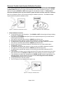
Electronic Throttle Control System Calibration Procedure
The 30-1820 / 30-1821 EMS, as delivered, requires a specific calibration procedure to be performed prior
to use. Before beginning this procedure, please be familiar with the location and function of the CRUISE
and SET/COAST buttons on the Cruise Control Steering Column Stalk as depicted in Figure 2. Also be
aware of the (green) CRUISE and SET indicator lights on the dashboard, Figure 3. This procedure
should be repeated any time any part of the ETC system has been serviced, removed, or replaced.
Note: Do not attempt to start or run the engine during the calibration procedure. The EMS will disable
engine start/running whilst in calibration mode.
Figure 2 - “CRUISE” and “SET/COAST” buttons
Figure 3 -“CRUISE” and “SET” indicator lights
1. Initial Calibration Procedure
a. Turn the ignition key to the ON position. The CRUISE and SET indicator lights will begin flashing
in unison at a medium rate.
b. Press and hold the CRUISE button (See Figure 4) for approximately three (3) seconds until the
indicator lights stop flashing.
c. There will be a brief delay after which the CRUISE light will flash once.
d. Ensure the accelerator pedal is not being depressed and is in the full “UP” position.
e. The SET indicator light will flash rapidly for a few seconds as the EMS calibrates this position.
f. There will be a brief delay after which the CRUISE light will flash twice.
g. Depress and hold the accelerator pedal to the floor and ensure it is in the full Wide Open
Throttle/“WOT” position.
h. The SET indicator light will flash rapidly for a few seconds as the EMS calibrates this position.
i. There will be a brief delay after which the CRUISE light will flash three times.
j. The SET indicator light will flash rapidly for several seconds as the EMS calibrates the ETC
throttle body.
k. If the calibration procedure was successful and all the ETC sensors and actuators are found to be
within tolerance then the CRUISE and SET indicator lights will flash in unison at a medium rate.
l. If the calibration procedure fails, indicated by the CRUISE and SET indicator lights flashing in an
alternating pattern, please reference the sections entitled ETC Diagnostics and Calibration
Troubleshooting elsewhere in this document.
m. Turn the ignition key to the OFF position.
n. The ETC system is now calibrated and ready for use.
Figure 4 – Pressing the “CRUISE” button
Page 9 of 20
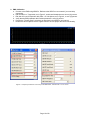
2. EMS Calibration
a. Connect to the EMS using AEM Pro. Reference the AEM Pro user manual if you need help
connecting.
b. Edit the Idle% vs. Target table, as in Figure 5, such that all breakpoints are at zero (0) percent.
c. Edit Idle A/C Load Comp and/or Idle Extra <12 Volt Options, as in Figure 6, to zero (0) percent.
d. Verify that the EMS parameter Idle Position parameter is zero (0) percent.
e. Perform the “Throttle Setup” procedure as described in the AEM Pro user manual.
f. Restore the above Options to their original values to ensure proper idle control functionality.
Figure 5 – Temporarily set the Idle% vs. Target table to zero
Figure 6 – Temporarily set Idle A/C Load Comp, Hi Idle RPM Offset, and Idle Extra < 12 Volt to zero
Page 10 of 20
Re-calibrating the Electronic Throttle Control System (ETC) Calibration
Once the ETC system calibration procedure has been performed, it should not need to be re-calibrated
unless one or more of the following is true:
• The APP sensor, TPS, or throttle body have been removed, replaced, or adjusted.
• The EMS has been removed and installed in a different vehicle.
• AEM Technical Support has requested it to be performed.
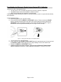
The following procedure describes the steps to re-activate calibration mode on a system that has already
been calibrated.
Activate Calibration Mode
a. Ensure the ignition key is in the OFF position.
b. Press and HOLD both the CRUISE and SET/COAST buttons. Please note that the CRUISE
button is activated by pressing the end of the Cruise Control Steering Column Stalk and the
SET/COAST button is activated by pulling the entire stalk downward as depicted in Figure 7.
Both buttons must be depressed and held prior to moving on to the next step.
Figure 7 - Pressing the “SET/COAST” and “CRUISE” buttons
c. Turn the ignition key to the ON position.
d. Keep holding both the CRUISE and SET/COAST buttons for approximately ten (10) seconds until
the CRUISE and SET indicator lights (Figure 3) begin flashing in unison at a medium rate.
e. Release the CRUISE and SET/COAST buttons.
f. Calibration mode has now been activated. Follow the steps in Electronic Throttle Control
System Calibration Procedure – Initial Calibration Procedure to complete the process.
Page 11 of 20
EMS Idle Control Calibration
The ETC idle control can be configured and calibrated via AEM Pro similarly to more traditional systems
that use an idle air bypass valve. There are a few calibration options that are set specifically to allow
proper ETC idle control and must not be changed from the values set forth in the 30-1820 startup
calibration. The options highlighted in red, in Figure 8, must remain set as depicted for predictable ETC
idle control. The other options that are not highlighted have been set up for stable idle control in the 301820 startup calibration but are, however, available for adjustment as the calibrator sees fit.
Figure 8 - Parameters highlighted in red must be set as depicted for predictable ETC Idle Control
Page 12 of 20
ETC Fault Management
The ETC system continuously monitors itself for proper operation. If a fault is detected then the system
will be placed in a failsafe mode and power to the electronic throttle body will be turned off. This will allow
the engine to start and idle at approximately 1500-2000 rpm as a “limp-home” mode but the throttle body
will not respond to accelerator pedal inputs.
The system will continue to monitor itself and assume that the throttle blade will be in its rest position
while in this un-powered failsafe mode. If it is detected that this is not the case then the system will enter
a second failsafe stage whereby the crank signal to the EMS is interrupted. The tachometer will drop to
zero and the EMS will not fire fuel injectors or ignition coils. If the engine is running, it will coast to a stop.
If the engine is not running, it will not start.
ETC Diagnostics
The AEM EMS ETC system uses the CRUISE and SET indicator lights on the dashboard to display
diagnostic information to the user. The indicator lights flash in different ways for different purposes as
described in the following sections.
Figure 9 - CRUISE and SET Indicator Lights as diagnostic outputs
Boot-Up
When the ignition key is turned on and the EMS is powered up, both of the CRUISE and SET
indicator lights will flash briefly to signify the ETC system has booted up and that the indicator
lights are functioning properly.
Fault Detected
When the ETC system detects a fault, the CRUISE and SET indicator lights will flash in an
alternating fashion to alert the user a fault has been detected. This will happen in one of two
situations:
1. Calibration Fault – A failed calibration will be detected if one of the sensors is found to be
out of the expected range during the calibration procedure. The indicator lights will flash
in an alternating pattern to alert the user of this fault for a period of approximately twenty
(20) seconds. After this time period, the CRUISE light will remain off and the SET
indicator light will flash a fault code. Please reference Table 1 for a description of the
fault codes. The system will flash the code repeatedly until the ignition is turned off.
1
2
3
4
5
Calibration Fault
APP Minimum
APP Maximum
TPS Minimum
TPS Maximum
RP / Relay
Table 1 – System Fault Code
2. Operational Fault – When the system detects a fault during normal operation (e.g.
driving, idling, etc), the indicator lights will repeatedly flash in an alternating pattern to
alert the user of this fault until the ignition key is turned off. Note that the ETC system will
Page 13 of 20
not be functional and the EMS may disable engine operation during this mode depending
on the severity of the fault.
Once the ignition has been turned off and then on again the indicator lights will flash the
fault code for the affected system. The affected ETC system code will be first flashed on
the CRUISE light after which the failure type will be flashed on the SET light. These
codes are listed in Table 2 and Table 3. The ETC system will remain un-activated until
the following boot-up cycle, i.e. key-off then key-on.
System
1
2
3
4
5
6
7
8
9
APP
TPSA
TPSB
Target
System Voltage
Motor Driver
WDR
EEPROM
N/A
1
2
3
4
5
6
7
8
9
Table 2 – System Fault Code
Failure Type
Out of Range
Noise
Disagreement
General
F2
N/A
N/A
N/A
N/A
Table 3 – Failure Type Fault Code
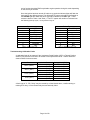
Troubleshooting Calibration Faults
A calibration fault will be reported if the Accelerator Pedal Position (APP) or Throttle Position
Sensor (TPS) sensors are found to be outside of the specification limits. Table 4 details the
electrical limits for these sensors.
Sensor
APP1 ( Main )
APP2 ( Sub )
TPS1 ( Main )
TPS2 ( Sub )
Mechanical Position
Minimum ( Idle )
Maximum ( WOT )
Minimum ( Idle )
Maximum ( WOT )
Minimum ( Idle )
Maximum ( WOT )
Minimum ( Idle )
Maximum ( WOT )
Voltage Limit (VDC)
1.00 ± 0.35
4.00 ± 0.45
1.00 ± 0.35
4.00 ± 0.45
0.70 ± 0.30
4.10 ± 0.45
1.45 ± 0.30
4.10 ± 0.45
Table 4 – Sensor Electrical Calibration Limits
A fault code of “5 - RP / Relay” may be caused by a fouled throttle bore, a malfunctioning or
missing ETC relay, or if the throttle body has mechanically failed.
Page 14 of 20
Troubleshooting Operational Faults
Should an operational fault be detected, please read and follow the following suggestions for
each system.
APP
•
•
•
Ensure the accelerator pedal position sensor is in good condition and plugged in.
Double-check that APP sensor is wired per OEM specifications.
Check all wiring for shorts or intermittent connections.
TPSA/TPSB
• Ensure the throttle position sensor is in good condition and plugged in.
• Double-check that throttle body/TPS sensor is wired per OEM specifications.
• Check all wiring for shorts or intermittent connections.
Target
• Ensure throttle body bore is clean and free from obstruction.
• Ensure vehicle battery is in good condition and properly charged.
System Voltage
• Ensure vehicle battery is in good condition and properly charged.
• Check all wiring for shorts or intermittent connections.
Motor Driver
• Double-check that throttle body/TPS sensor is wired per OEM specifications.
• Check throttle body wiring for shorts or intermittent connections.
• Ensure EMS has not been installed in an area of extreme heat ( > 120°C)
WDR
•
Contact AEM EMS Technical Support
EEPROM
• Perform ETC system calibration
• Restore ETC system factory calibration
• Contact AEM EMS Technical Support
Page 15 of 20
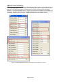
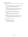
Pinout Chart: AEM 30-1820 / 30-1821 EMS
PnP
These pins are used in the AEM-supplied startup calibration. They can be reconfigured by the end
user.
Available
Not used by the startup calibration. Modifications to the OEM wiring may be required before use
Dedicated
The location of these pins is fixed and must not be changed
Pin #
2004 STI 2.5L / 2005-2006 STI 2.5L
AEM EMS 30-1820 / 30-1821
I/O
A1
A2
A3
A4
A5
A6
A7
A8
A9
A10
A11
A12
A13
A14
A15
A16
A17
A18
A19
A20
A21
A22
A23
A24
A25
A26
A27
A28
A29
A30
A31
A32
A33
A34
Clutch Switch
Front Oxygen Sensor Heater (Signal 2)
Front Oxygen Sensor Heater (Signal 1)
----GND (Front Oxygen A/F Heater 2)
GND (Front Oxygen A/F Heater 1)
Tumble Generator Valve RH (close)
Tumble Generator Valve RH (open)
Tumble Generator Valve LH (close)
Tumble Generator Valve LH (open)
Pressure control solenoid valve (fuel tank)
Drain Valve
Purge Control solenoid valve
Main light ("Cruise" lamp on dash)
Cruise Set light ("Set" lamp on dash)
Malfunction Indicator Lamp
Oil flow control solenoid (RH) Signal (+)
Oil flow control solenoid (LH) Signal (+)
----Alternator
Engine Speed Output (to OEM tachometer)
Fuel Tank sensor control valve
Front Oxygen sensor shield
Front Oxygen sensor signal (-)
--Oil flow control solenoid (RH) Signal (-)
Oil flow control solenoid (LH) Signal (-)
----Wastegate Control solenoid valve
Front Oxygen sensor signal (+)
Engine Ground
Switch #3
Injector #5
Injector #6
----Injector #7
Injector #8
Idle #6
Idle #5
Idle #8
Idle #7
Low Side Driver #3
Low Side Driver #2
Low Side Driver #4
Cruise light
Set light
Low Side Driver #10
+12V Switched Ignition Power
+12V Switched Ignition Power
----Low Side Driver #1
Tach Output (LS7)
Low Side Driver #11
--Lambda #1
--Injector #9
Injector #10
----PW #2
High Side Driver #2
Power Ground
In Available, switch should connect to +12V when closed
Out Available, can be used for additional injectors (1.5A max)
Out Available, can be used for additional injectors (1.5A max)
Not Used
Not Used
Out Available, can be used for additional injectors (1.5A max)
Out Available, can be used for additional injectors (1.5A max)
Out PnP for TGV
Out PnP for TGV
Out PnP for TGV
Out PnP for TGV
Out Available, can be used for Switched Ground (1.5A max)
Out Available, can be used for Switched Ground (1.5A max)
Out Available, can be used for Switched Ground (1.5A max)
Out Dedicated, ETC system output
Out Dedicated, ETC system output
Out PnP for MIL
Out Dedicated
Out Dedicated
Not Used
Not Used
Out Available, can be used for Switched Ground (1.5A max)
Out PnP for Tachometer
Out Available, can be used for Switched Ground (1.5A max)
Not Used
In PnP for O2 #1 signal
Not Used
Out PnP for VVC #1 (Active Valve Control Solenoid)
Out PnP for VVC #2 (Active Valve Control Solenoid)
Not Used
Not Used
Out PnP for Boost Control Solenoid
Out Available, can be used for Switched +12V (1.5A max)
In Dedicated
Page 16 of 20
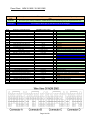
Availability / Notes
Pin #
B1
B2
B3
B4
B5
B6
B7
B8
B9
B10
B11
B12
B13
B14
B15
B16
B17
B18
B19
B20
B21
B22
B23
B24
B25
B26*
B27*
B28
B29
B30
B31
B32
B33
B34
B35
2004 STI 2.5L / 2005-2006 STI 2.5L
GND (Power Supply)
Rear Oxygen Sensor heater signal
--GND (Power Supply)
Control Unit Power Supply
Control Unit Power Supply
--Camshaft position sensor (LH)
Camshaft position sensor (RH)
Crankshaft position sensor Signal (+)
--GND (Ignition System)
----Ignition Control #4
Ignition Control #3
Ignition Control #2
Ignition Control #1
Back-up Power Supply
----Crankshaft position sensor Signal (-)
--Radiator Fan relay 2 control
Radiator Fan relay 1 control
Fuel Pump control unit Signal 1 / Vehicle Speed*
Vehicle Speed / Fuel Pump control unit sig 1*
------Crankshaft Position sensor Shield
--A/C relay control
--Electronic Throttle control motor relay
AEM EMS 30-1820 / 30-1821
Power Ground
----Power Ground
+12V Switched Ignition Power
+12V Switched Ignition Power
--Vehicle Speed
Cam
Crank
--Power Ground
----Coil #5
Coil #3
Coil #2
Coil #1
Permanent +12V
----Timing Ground
--Low Side Driver #9
Low Side Driver #8
FPCU circuit (Idle#2) / Spare Speed*
Spare Speed / FPCU circuit (Idle#2)*
------Power Ground
--Low Side Driver #6
--ETC relay control
I/O
Availability / Notes
In Dedicated
Not Used
Not Used
In Dedicated
In Dedicated
In Dedicated
Not Used
In PnP for Cam sensor (LH)
In PnP for Cam sensor (RH)
In Dedicated
Not Used
In Dedicated
Not Used
Not Used
Out PnP for Coil #5
Out PnP for Coil #3
Out PnP for Coil #2
Out PnP for Coil #1
In Dedicated
Not Used
Not Used
Out Dedicated
Not Used
Out PnP for A/C Fan
Out PnP for Radiator Fan
Out* Dedicated, 0-5V signal to Fuel Pump Control Unit
In* PnP for wheel speed input, shared with speedometer
Not Used
Not Used
Not Used
Out Dedicated
Not Used
Out PnP for A/C compressor clutch
Not Used
Out Dedicated
* Pin function is different between 2004 / 2005-2006 models
Page 17 of 20
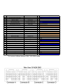
Pin #
2004 STI 2.5L / 2005-2006 STI 2.5L
AEM EMS 30-1820 / 30-1821
C1
C2
C3
C4
C5
C6
C7
C8
C9
C10
C11
C12
C13
C14
C15
C16
C17
C18
C19
C20
C21
C22
C23
C24
C25
C26
C27
C28
C29
C30
C31
C32
C33
C34
C35
----Fuel Injector #4
Fuel Injector #3
Fuel Injector #2
Fuel Injector #1
Main switch
Brake Switch 2
Brake Switch 1
Resume / Accel switch
Set / Coast switch
Fuel Temperature Sensor signal
Intake Air Temperature sensor signal
Engine Coolant Temperature sensor
Accelerator Pedal Position sensor Power
Electronic Throttle control Power Supply
Accelerator Pedal Position sensor Main
Electronic Throttle control Main
--Fuel Level Sensor
Fuel Tank Pressure Sensor signal
Manifold Absolute Pressure sensor signal
Mass Air Flow sensor Signal
-Knock Sensor Signal
Tumble Generator Valve position sensor LH
Tumble Generator Valve position sensor RH
Accelerator Pedal Position sensor Sub
Electronic Throttle control Sub
--Mass Air Flow sensor GND
Mass Air Flow sensor Shield
Knock Sensor Shield
Accelerator Pedal Position sensor GND
GND (sensor)
----Injector #4
Injector #3
Injector #2
Injector #1
Main Switch
--Switch #2
--Set Switch
EGT #1
AIT
Coolant
Accelerator Pedal +5V reference
+5V Sensor reference
Accelerator Pedal signal 1
TPS / Electronic Throttle signal 1
------MAP
MAF
-Knock #1
Spare Temp (ADCR14)
PR Pressure (ADCR11)
Accelerator Pedal signal 2
Electronic Throttle signal 2
--Sensor Ground
Power Ground
Power Ground
Accelerator Pedal Ground
Sensor Ground
Page 18 of 20
I/O
Out
Out
Out
Out
In
In
In
In
In
In
Out
Out
In
In
In
In
In
In
In
In
Out
Out
Out
Out
Out
Out
Availability / Notes
Not Used
Not Used
PnP for Injector #4
PnP for Injector #3
PnP for Injector #2
PnP for Injector #1
Dedicated, ETC system input
Not Used
Available, switch should connect to GND when closed
Not Used
Dedicated, ETC system input
Available, RTD type thermistor
PnP for Air Intake Temp sensor, RTD type thermistor
PnP for Coolant Temp sensor, RTD type thermistor
Dedicated, reference power to accelerator pedal
Dedicated, sensor reference power
Dedicated, main 0-5V signal from accelerator pedal
Dedicated, main 0-5V signal from throttle motor
Not Used
Not Used
Not Used
PnP for Manifold Pressure sensor
Available, 0-5V MAF input signal
Not Used
Dedicated
PnP for TGV
PnP for TGV
Dedicated, secondary 0-5V signal from accelerator pedal
Dedicated, secondary 0-5V signal from throttle motor
Not Used
Dedicated
Dedicated
Dedicated
Dedicated, ground to accelerator pedal
Dedicated
Pin #
D1
D2
D3
D4
D5
D6
D7
D8
D9
D10
D11
D12
D13
D14*
D15*
D16*
D17*
D18
D19
D20
D21
D22
D23
D24
D25
D26
D27
D28
D29
D30
D31
2004 STI 2.5L / 2005-2006 STI 2.5L
GND (control systems)
GND (control systems)
Electronic Throttle control GND (sensor)
Electronic Throttle control motor (-)
Electronic Throttle control motor (+)
Electronic Throttle control Motor Power
GND (Injectors)
Starter switch
Neutral Position switch
Power Steering oil pressure switch
Rear Defogger switch
(not used by stock ECU)
Blower Fan switch
Test Mode Connector / Ignition Switch*
Ignition Switch / Test Mode Connector*
AC Switch / Main Relay control*
Main Relay control / AC Switch*
----SSM / GST communication line
------Blow-by Leak diagnosis signal
Rear Oxygen sensor Signal
----Fuel Pump control unit Signal 2
---Rear Oxygen sensor Shield
AEM EMS 30-1820 / 30-1821
Power Ground
Power Ground
Electronic Throttle Ground
Electronic Throttle Motor Electronic Throttle Motor +
Electronic Throttle Power
Power Ground
Main Relay circuit (Switch #1)
----Switch #4
--Switch #5
--- / Main Relay circuit (Switch#1)*
Main Relay circuit (Switch #1) / --- *
Switch #6 / Main Relay circuit (FM) *
Main Relay circuit (FM) / Switch #6 *
----EGT #2
------EGT #3
Lambda #2
----Low Side Driver #5
EGT #4
--Power Ground
I/O
In
In
Out
Out
Out
In
In
In
In
In
*
In*
In*
Out*
In
In
In
Out
In
Out
Availability / Notes
Dedicated
Dedicated
Dedicated
Dedicated, ETC system output
Dedicated, ETC system output
Dedicated, ETC power
Dedicated
Dedicated
Not Used
Not Used
Available, switch should connect to GND when closed
Not Used
Available, switch should connect to GND when closed
Not Used
Dedicated
PnP for A/C request switch
Dedicated, activates main relay with switched GND
Not Used
Not Used
Available, RTD type thermistor
Not Used
Not Used
Not Used
Available, RTD type thermistor
Available, O2 #2 signal
Not Used
Not Used
Available, can be used for Switched Ground (1.5A max)
Available, RTD type thermistor
Not Used
Dedicated
* Pin function is different between 2004 / 2005-2006 models
Page 19 of 20
AEM Electronics Warranty
Advanced Engine Management Inc. warrants to the consumer that all AEM Electronics
products will be free from defects in material and workmanship for a period of twelve
months from date of the original purchase. Products that fail within this 12-month
warranty period will be repaired or replaced when determined by AEM that the product
failed due to defects in material or workmanship. This warranty is limited to the repair or
replacement of the AEM part. In no event shall this warranty exceed the original
purchase price of the AEM part nor shall AEM be responsible for special, incidental or
consequential damages or cost incurred due to the failure of this product. Warranty
claims to AEM must be transportation prepaid and accompanied with dated proof of
purchase. This warranty applies only to the original purchaser of product and is nontransferable. All implied warranties shall be limited in duration to the said 12-month
warranty period. Improper use or installation, accident, abuse, unauthorized repairs or
alterations voids this warranty. AEM disclaims any liability for consequential damages
due to breach of any written or implied warranty on all products manufactured by AEM.
Warranty returns will only be accepted by AEM when accompanied by a valid Return
Merchandise Authorization (RMA) number. Product must be received by AEM within 30
days of the date the RMA is issued.
Please note that before AEM can issue an RMA for any electronic product, it is first
necessary for the installer or end user to contact the tech line at 1-800-423-0046 to
discuss the problem. Most issues can be resolved over the phone. Under no
circumstances should a system be returned or a RMA requested before the above
process transpires.
AEM will not be responsible for electronic products that are installed incorrectly,
installed in a non approved application, misused, or tampered with.
Any AEM electronics product can be returned for repair if it is out of the warranty period.
There is a minimum charge of $50.00 for inspection and diagnosis of AEM electronic
parts. Parts used in the repair of AEM electronic components will be extra. AEM will
provide an estimate of repairs and receive written or electronic authorization before
repairs are made to the product.
Page 20 of 20