1
1.2 INSTALLATION RESTRICTIONS
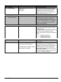
Hazardous-duty systems (Ex) - Refer to the MicroTREK 2-wire Installation and Programming manual for further information
on installing gauges approved for use in hazardous locations.
Check that the flange, gasket and probe materials are compatible with the product.
Read the information given on the converter nameplate, the flange markings and specifications in the approval certificates.
1.3 MOUNTING ON THE TANK
1.3.1
INSTALLATION INSTRUCTIONS: GENERAL NOTES
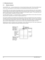
The fitter should give some thought to tank fittings and tank shape.
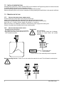
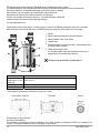
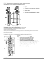
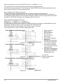
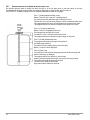
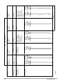
NOZZLE POSITION IN RELATION TO THE TANK WALLS AND OTHER OBJECTS INSIDE THE TANKS
(Warning: this free area will depend on the probe type selected: refer to later on in this section)
type of tank roof, i.e. floating, concrete, integral, etc; and base, i.e. conical, etc.
Whenever working on an installation, remember to: Disconnect the power supply before starting work.
However, the gauge may be installed when the tank contains product.
1.3.2
INSTALLATION INSTRUCTIONS: NOZZLE
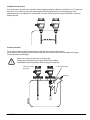
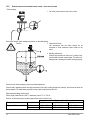
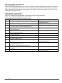
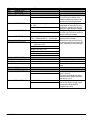
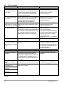
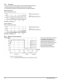
Threaded process connections
Nozzle height
The simplest and most economic way is to mount the
Recommendation
Do not fit a nozzle longer than its diameter,
MicroTREK 2-wire directly on the tank with the 1”G or
especially for single probes and powder
1”NPT threaded connection.
applications
h ≤ Ød
, where h = nozzle height and
d = nozzle diameter
Contact NIVELCO if this relationship cannot be respected.
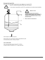
Nozzles extending into tank - Caution: Do not use nozzles that extend into the tank. This will disturb the emitted pulse.
8
MicroTREK 2-wire