1
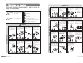
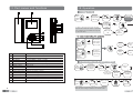
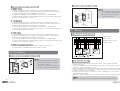
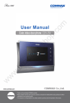
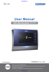
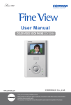
Greetings
1. Thank you for purchasing our CommaxⓇ product.
2. You should read this user’s manual carefully before operating the unit.
Table of Contents
Greetings.....................................................................................1
Table of Contents .......................................................................1
Ⅰ.Warnings and caution.........................................................2
Ⅱ. Part names and functions..................................................4
Ⅲ. Operation..............................................................................5
Ⅳ. Installation............................................................................6
Ⅴ. Wiring....................................................................................7
Ⅵ. Part list .................................................................................8
Ⅶ. Specifications ......................................................................8
MEMO.
1
Ⅰ.Warnings and caution
Please follow the things described below in order to prevent any
danger or property damage.
Prohibition.
Warning
It may cause a serious damage or
injury if violated.
No disassembly
No touch
Cleaning & Use
Warning
Please dont disassemble,
repair or rebuild this product
arbitrarily (please contact the
service center if a repair is
needed.
It may cause an electric
shock or fire.
If an abnormal sound, burning
smell or smoke is coming out
of the product, please plug out
the power cable and contact a
service center.
It may cause an electric
shock or fire.
Please dont insert any
metallic or burnable materials
into the ventilation hole.
It may cause an electric
shock or fire.
Please use only the designated
batteries for the products of
using DC power.
It may cause an electric
shock or fire.
Must follow strictly.
Caution
Shows plugging out the power cord
without an exception
It may cause a minor damage or
injury if violated.
Caution
Shows the warning and caution for an electric shock.
Shows the warning and caution for a fire.
Please plug the power cable
firmly into the inner end
It may cause a fire.
Please hold the plug tightly
when unplugging the power
cable (a part of the copper
wire may be disconnected if
the grabbing is only made on
the cord when pulling out the
cable).
It may cause an electric
shock or fire
When connecting the power
cables after cutting the cable,
please install the product with
power off
It may cause an electric
shock or fire
Please be careful when using
an AC circuit breaker since
there is a possibility of an
electric shock.
Please check the use voltage
and current for the DC-only
products and use the
appropriate rectifier.
It may cause a fire.
Please avoid direct rays of the
sun or heating devices at a
time of installation.
It may cause a fire.
When cleaning the product,
please rub it with a soft and
dry cloth after plugging out
the power cable. (Please dont
use any chemical products
such as wax, benzene, alcohol
or cleanser.)
Please dont drop the product
on the ground and dont apply
a shock .
It may cause a failure.
Please use the designated
connection cable within the
maximum calling distance
designated for the product
It may reduce the product
performance.
2
Please dont install the
product in the place where
there is much oil, smoke or
humidity.
It may cause an electric
shock or fire.
Please dont bend the power
cable excessively or it may
cause an electric shock.
fire when using a damaged
power cable.
Please dont install the
product with the lightening
and thunder.
It may cause an electric
shock or fire.
Please dont handle the power
cable with a wet hand.
It may cause an electric
shock.
Please dont use and connect
this product with other
products with different rated
voltage
It may cause a disorder or
fire.
Please plug out the power
cable from the socket when
not using it for a long period
of time.
It may shorten the product
lifespan or cause a fire.
When installing the product
that generates heat, please
install the product away from
the wall (10cm) for the
ventilation.
It may cause a fire due to
the increased internal
temperature.
Cleaning & Use
Power & Installation
Please dont use several
products at the same time on
one power socket.
It may cause a fire due to an
abnormal overheating.
Power & Installation
Warning
When installing the product,
please fix it firmly while using
the wall-mounting unit and
screws.
It may cause an injury from
the falling object.
Please dont install the
product on an unstable place
or small support board.
It may cause an injury if it
falls down while in use.
3
Ⅱ. Part names and functions
Ⅲ. Operation
1. Calling of visitor
The visitor
presses the
call button on
the camera
The visitor’
s
image appears
on the monitor
A chime
sounds
A view of the front door can be seen
anytime the entrance button is pressed
and a dialog can be made with anyone
at the front door.
Open the door
The door release function
operates only when the visitor’s
image is displayed on the screen
Dialog begins
Dialog
duration 60
seconds at
a time
To check
Hang-up
the
handset
Ends the
call
* In case of connecting two cameras
The
visitor
presses
the call
button on the
camera1
No.
1
2
3
4
5
6
7
8
9
10
11
12
13
14
4
Part name
Handset
Screen
UP Button
Door open button
Interphone button
Power status
DOWN Button
Entrance button
Volume control switch
BRIGHT setting button
COLOR setting button
CONT setting button
RESET button
Power switch
Description
The phone's handset receiver
3.5"TFT LCD
Control BRIGHT / CONT / COLOR
Door strike of Relevant camera is run during the status of door communication
Call to interphone with picking up handset
LED Light
Control BRIGHT / CONT / COLOR
Press when to want to check the entrance status
Control incoming volume
Press the setting button to control BRIGHT
Press the setting button to control COLOR
Press the setting button to control CONT
Button for fixing the default of screen on Color, Brightness
ON / OFF switch for power supply
The
visitor
presses
the call button
on the
camera2
A chime
sounds
A chime
sounds
The visitor’s
image appears
on the monitor
The visitor’
s
image appears
on the monitor
Press
once
Camera 1
view
Press
twice
Camera 2
view
2. Communication with the optional Interphone
A visitor
calls from
the entrance
A chime rings
simultaneously from
both the monitor
and interphone
Dialog begins
A three-way
conversation can take
place if the monitor or interphone is
picked up simultaneously
Call
from the
monitor
A‘beep’will
be heard
Dialog begins
Open the
door
Call to the
monitor
Dialog between the interphone and camera is possible only
when the visitor’s image is visible on the monitor screen.
End the
dialog
Hang-up the
handset
Dialog begins
5
3. BRIGHT / COLOR / CONT setting
2. Installation Method of camera
1). BRIGHT setting
① Press the entrance button in status of hooking well (LED blinking status)
② Press the BRIGHT button in the right for 2 seconds in status of the screen on
③ Power LED is blinked as fast (BRIGHT control mode)
④ Control the BRIGHT as the user wants by pressing UP / DOWN button
⑤ Save the fixed default by pressing BRIGHT button for 2 seconds after setting done
⑥ Power LED is blinked as normal
2). COLOR setting
① Press the entrance button in status of hooking well (LED blinking status)
② Press the COLOR button in the right for 2 seconds in status of the screen on
③ Power LED is blinked as fast (COLOR control mode)
④ Control the COLOR as the user wants by pressing UP / DOWN button
⑤ Save the fixed default by pressing COLOR button for 2 seconds after setting done
⑥ Power LED is blinked as normal
3). CONT setting
① Press the entrance button in status of hooking well (LED blinking status)
② Press the CONT button in the right for 2 seconds in status of the screen on
③ Power LED is blinked as fast (CONT control mode)
④ Control the CONT as the user wants by pressing UP / DOWN button
⑤ Save the fixed default by pressing CONT button for 2 seconds after setting done
⑥ Power LED is blinked as normal
Note
① Do not install the camera where
it is exposed to Direct sunlight
② Keep cleaning up its lens to
capture good views.
SCREW T4(2EA)
SCREW M3
DRC-40CK
Ⅴ. Wiring
1. Wires descriptions of camera
① Red: Voice
② Blue: GND
③ Yellow: Power (+12V)
④ White: Video
4). RESET (Video Status initialization)
① Press the BRIGHT button for 2 seconds in status of the screen on
② Video status is initialized to the factory delivery status
Ⅳ. Installation
1. Installation Method of camera monitor
Note
① Avoid the range of direct sunlight
② Recommended height is pertinent
from 1450 ~ 1500mm
③ Avoid the installation near magnetic
activity, humid temperatures and gas
6
2. Wiring precautions
1). If high voltage cables are present in the vicinity, use a coaxial cable with
metal outer casing.
2). If any internal wires are exposed through mis-wiring, it may cause a short and
become a cause of malfunction or fire.
3).When connecting the monitor and camera, please make sure that the monitor
power is off.(turn on the power after plugging the AC power cord into the outlet)
4). Attend the wiring as it is a polarity
5). make it short for camera 2 connector in case of installing only one camera
(the default factory state)
6).Delete the optional camera pin of the above camera when to install two cameras
Note
Image and call quality can be down when the monitor is expanded randomly.
7
Ⅵ. Part list
Bracket for wall mount
Manual
Body of CDV-35N
T4 X 18
M3 X 6
Screw for wall mount Screw for body
4P Connector
Ⅶ. Specifications
"
Model
%6-1+"2/6%+)
"<
;
2157036-21
3)4%6-21%9-070#
#-4-1+0)6,2(
!2%%0)4%71-68-4)532/%4-6:!2%116)43,21)8-4)532/%4-6:
21-624
'0
20071-'%6-21
7//(73/)9%1(5)6
%//621)
%//5271(*420'%0)4%)/)'6421-'',-0)16)43,21))/)'6421-'&7;;)4
21-624-53/%:
=
5)'
-56%1')*420%0)4% 0@
0@
0@
#24.-1+!)03)4%674) <
> ? <
?
8
#)-+,6
.+%5)(212(:
-0)15-2100
#$$
%5)(21%9,)-+,62*,%1(5)6
513-11, Sangdaewon-dong, Jungwon-gu, Seongnam-si, Gyeonggi-do, Korea
Int’l Business Dept. : Tel.; +82-31-7393-540~550 Fax.; +82-31-745-2133
Web site : www.commax.com
Printed In Korea / 2009.04