1
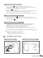
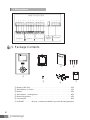
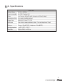
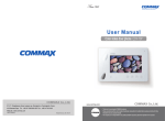
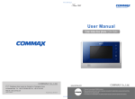
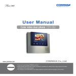
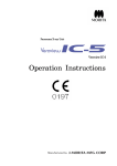
User Manual
COLOR VIDEO DOOR PHONE CDV-35H
513-11,
Sangdaewon-dong,
Jungwon-gu,
Seongnam-si,
Gyeonggi-do,
Korea
513-11,
Sangdaewon-dong,
Jungwon-gu,
Seongnam-si,
Gyeonggi-do,
Korea
Business
Dept.
: +82-31-7393-540~550
: +82-31-745-2133
Int’l Int’l
Business
Dept.
Tel.Tel.
: +82-31-7393-540~550
Fax.Fax.
: +82-31-745-2133
: www.commax.com
WebWeb
site site
: www.commax.com
PM0735H00010
Printed In Korea / 2011.10.104
• Thank
youpurchasing
for purchasing
COMMAX
products.
• Thank
you for
COMMAX
products.
for safety)
before
a product
follow
• Please
carefully
this User’s
Guide
(in particular,
precautions
• Please
carefully
readread
this User’s
Guide
(in particular,
precautions
for safety)
before
usingusing
a product
and and
follow
instructions
to ause
a product
exactly.
instructions
to use
product
exactly.
• The
company
not responsible
for safety
any safety
accidents
caused
by abnormal
operation
of product.
the product.
• The
company
is notisresponsible
for any
accidents
caused
by abnormal
operation
of the
Greetings
1. Thank you for purchasing Commax product.
2. You should read this user’s manual carefully before operating the unit.
Table of Contents
Greetings
----------------------------------------------------------1
1. Warnings and caution - - - - - - - - - - - - - - - - - - - - - - - - - - - - - - - - - - - - - - - - - - - - - - - - - - - - 2
2. Part names and functions - - - - - - - - - - - - - - - - - - - - - - - - - - - - - - - - - - - - - - - - - - - - - - - - - 4
3. Operation
----------------------------------------------------------4
4. Installation and wiring - - - - - - - - - - - - - - - - - - - - - - - - - - - - - - - - - - - - - - - - - - - - - - - - - - - - 5
5. Package Cotents - - - - - - - - - - - - - - - - - - - - - - - - - - - - - - - - - - - - - - - - - - - - - - - - - - - - - - - 6
6. Specifications - - - - - - - - - - - - - - - - - - - - - - - - - - - - - - - - - - - - - - - - - - - - - - - - - - - - - - - - - - 7
MEMO.
1
1. Warnings and caution
Please follow the things described below in order to prevent any
danger or property damage.
Warning
Prohibition.
No disassembly
It may cause a serious damage or injury if
violated.
No touch
Caution
Must follow strictly.
It may cause a minor damage or injury if violated.
Shows plugging out the power cord
without an exception
Shows the warning and caution for an electric shock.
Shows the warning and caution for a fire.
Power & Installation
Warning
2
Please don’t use several
products at the same time on
one power socket.
·It may cause a fire due to an
abnormal overheating.
Please don’t bend the power
cable excessively or it may
cause an electric shock.
·fire when using a damaged
power cable.
Please don’t handle the power
cable with a wet hand.
·It may cause an electric
shock.
Please plug out the power
cable from the socket when
not using it for a long period
of time.
·It may shorten the product
lifespan or cause a fire.
Please don’t install the
product in the place where
there is much oil, smoke or
humidity.
·It may cause an electric
shock or fire.
Please don’t install the
product with the lightening
and thunder.
·It may cause an electric
shock or fire.
Please don’t use and connect
this product with other
products with different rated
voltage
·It may cause a disorder or
fire.
When installing the product
that generates heat, please
install the product away from
the wall (10cm) for the
ventilation.
·It may cause a fire due to
the increased internal
temperature.
Cleaning & Use
Warning
Please don’t disassemble,
repair or rebuild this product
arbitrarily (please contact the
service center if a repair is
needed.
·It may cause an electric
shock or fire.
If an abnormal sound, burning
smell or smoke is coming out
of the product, please plug out
the power cable and contact a
service center.
·It may cause an electric
shock or fire.
Please don’t insert any
metallic or burnable materials
into the ventilation hole.
·It may cause an electric
shock or fire.
Please use only the designated
batteries for the products of
using DC power.
·It may cause an electric
shock or fire.
Cleaning & Use
Power & Installation
Caution
Please plug the power cable
firmly into the inner end
·It may cause a fire.
Please hold the plug tightly
when unplugging the power
cable (a part of the copper
wire may be disconnected if
the grabbing is only made on
the cord when pulling out the
cable).
·It may cause an electric
shock or fire
When connecting the power
cables after cutting the cable,
please install the product with
power off
·It may cause an electric
shock or fire
Please be careful when using
an AC circuit breaker since
there is a possibility of an
electric shock.
Please check the use voltage
and current for the DC-only
products and use the
appropriate rectifier.
·It may cause a fire.
Please avoid direct rays of the
sun or heating devices at a
time of installation.
·It may cause a fire.
When cleaning the product,
please rub it with a soft and
dry cloth after plugging out
the power cable. (Please don’t
use any chemical products
such as wax, benzene, alcohol
or cleanser.)
Please don’t drop the product
on the ground and don’t apply
a shock .
·It may cause a failure.
Please use the designated
connection cable within the
maximum calling distance
designated for the product
·It may reduce the product
performance.
When installing the product,
please fix it firmly while using
the wall-mounting unit and
screws.
·It may cause an injury from
the falling object.
Please don’t install the
product on an unstable place
or small support board.
·It may cause an injury if it
falls down while in use.
3
2. Part names and functions
No.
1
2
3
4
5
6
7
8
9
Part name
Monitor
Speaker
Talk Button
Monitoring button
No function
Microphone
Door open button
Interphone button
Power indicator
No.
Part name
10
Menu button
11
SEL button
12
UP button
13
DOWN button
14 Adjustment dial for calling sound
15 Adjustment dial for talk volume
16
Power button
17
No function
18
Terminal
- Adjustment dial for calling sound: Use to adjust calling sound
- Adjustment dial for talk volume: Use to adjust talk volume from counter side.
- DIP switch for camera setting: Use to set up the camera.
Note : It shall be set as camera using mode from manufacturer.
3. Operation
1. Calling from visitor
1). When visitor presses the call button on the camera, the chime sounds and appears visitor’ s image on the screen.
2). Press talk button (
) and communicate with visitor. (Maximum 60 seconds is available to talk on the phone)
3). Press talk button(
) again to close and return standby mode after finish the talk.
4). Press door open button ( ) while on the phone to release the door with melody.
4
2. Communication with interphone
1). When press talk button (
) on standby status, appears speaker mark on the screen.
And then, press interphone button ( ) to call the interphone. (Maximum 60 seconds available to talk)
2). In case of calling from interphone to monitor, electric melody sounds.
Press talk button (
) to communication.
3). When you have a call from camera while on the phone with interphone, visitor’s image should be showed to
monitor. It shall be possible to talk between each unit, monitor, interphone and camera.
Note : When you finish talk with visitor or interphone, you have to press talk button again to close the talk mode.
3. Monitoring
1). When you press monitoring button (
), monitor shows you outside image during 30 minutes.
2). Monitor can be connected up to 2 cameras and shows you the outside image in order, camera1- camera2 by
each press monitor button(
).
4. Brightness and color setting
1). To Adjust brightness or color resolution, use the button on the right under operation mode.
① Press MENU button to enter“Control Menu”. Press SELECT button to appear basic menu.
② Control the each menu as the user wants by pressing UP/DOWN button.
③ When you press Select button, save the new data and return to basic menu.
④ If you press the Reset button, and press “SELECT”button, all conditions return manufacturer default.
Caution: After changing any conditions, press MENU button to return standby mode under basic menu.
Note : MENU Button – Enter adjustment and close the MENU
SEL Button – Select subject and move previous menu.
UP/DOWN Button – Move each menu and change each value.
4. Installation and Wiring
1. Installation diagram
2. Standard Height of Monitor
SCREW M3 X 6mm
SCREW T4 X 18mm
5
3. Wiring diagram
MONITOR (CDV-35H)
1 2 3 4
1 2 3 4
1 2 3 4
1 2 3 4
1 2 3 4
1 2 3 4
CAMERA 1
CAMERA 2
INTERPHONE
1 2 3 4
CAMERA 2 PROGRAM
SELECT
5. Package Contents
②
③
④
①
⑤
①
②
③
④
⑤
⑥
⑦
6
⑥
Monitor (CDV-35H) . . . . . . . . . . . . . . . . . . . . . . . . . . . . . . . . . . . . . . . . . . . . . . . .1EA
Wall Bracket for mount . . . . . . . . . . . . . . . . . . . . . . . . . . . . . . . . . . . . . . . . . . .1EA
Manual . . . . . . . . . . . . . . . . . . . . . . . . . . . . . . . . . . . . . . . . . . . . . . . . . . . . . . . . . .1EA
Wall Bracket mouting Screw . . . . . . . . . . . . . . . . . . . . . . . . . . . . . . . . . . . . . . .4EA
Monitor fixing Screw . . . . . . . . . . . . . . . . . . . . . . . . . . . . . . . . . . . . . . . . . . . . . . .1EA
Connetor(4P) . . . . . . . . . . . . . . . . . . . . . . . . . . . . . . . . . . . . . . . . . . . . . . . . . . . . .2EA
2P SHUNT . . . . . . . .Only No. 1 camera is available if you insert 2P shunt(short pin)
⑦
6. Specifications
CDV-35H
Rating Voltage
100-240~, 50/60Hz
Wiring
Door Camera: 4Wires(Polarity), Interphone: 4Wires(Polarity)
Screen Size
8.89Cm(3.5") Color TFT-LCD
Distance
Camera : 50m(Φ0.65) / Interphone : 20m(Φ0.65)
Form Size
133(W) x 209(H) x 31(D) ㎜
Power consumption Max : 10W, Standby : 4W
Transmission Way Voice switch circuit(Hands free)
Call Sound
From a door camera: electronic chime, From an Interphone : "Beep"
Operating temperature 0 ~+40℃ (32℉ ~ 104℉)
7
Memo
8