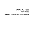
1
Installation & Service Instructions
A10314
Serial Bus PROFIBUS Adapter,
Series A (RPSSCPBA)
ISSUED: August, 2007
Supersedes: None
! WARNING
To avoid unpredictable system behavior that can cause personal injury
and property damage:
• Disconnect electrical supply (when necessary) before installation,
servicing, or conversion.
• Disconnect air supply and depressurize all air lines connected to this
product before installation, servicing, or conversion.
• Operate within the manufacturer’s specified pressure, temperature,
and other conditions listed in these instructions.
• Medium must be moisture-free if ambient temperature is below
freezing.
• Service according to procedures listed in these instructions.
• Installation, service, and conversion of these products must be
performed by knowledgeable personnel who understand how
pneumatic products are to be applied.
• After installation, servicing, or conversion, air and electrical supplies
(when necessary) should be connected and the product tested for
proper function and leakage. If audible leakage is present, or the
product does not operate properly, do not put into use.
• Warnings and specifications on the product should not be covered by
paint, etc. If masking is not possible, contact your local representative
for replacement labels.
Introduction
Follow these instructions when installing, operating, or servicing the
product.
Serial Bus PROFIBUS Adapter, Series A
(RPSSCPBA)
The sealed IP67 housing of these adapters requires no enclosure.
(Note that environmental requirements other than IP67 may require
an additional appropriate housing.) PROFIBUS connectors are
sealed M12 (micro) style. The PROFIBUS adapter is shown below.
Shielding
(See page 3 for details)
RPSSCPBA
RPSSCPBA
Safety Guide
For more complete information on recommended application guidelines,
see the Installation Safety Guidelines section of Bulletin 600 (Form
A10309) or you can download the Installation Safety Guidelines at:
www.rosscontrols.com/rosslit.htm.
M12 Connector
Station
Address
Switches
Mini 7/8"
Auxiliary
Power
Connector
Profibus DP
Profibus Out
Profibus In
Adapter
Status
Profibus
Status
X10
X1
PointBus
Status
System
Power
PWR
Adapter
Power
ROSS
! WARNING
FAILURE OR IMPROPER SELECTION OR IMPROPER USE OF THE
PRODUCTS AND/OR SYSTEMS DESCRIBED HEREIN OR RELATED
ITEMS CAN CAUSE DEATH, PERSONAL INJURY AND PROPERTY
DAMAGE.
Serial Bus PROFIBUS Adapter User Manual
The Serial Bus PROFIBUS Adapter User Manual is not available
at this time. Please refer to Rockwell Automation 1734 POINT
I/O PROFIBUS Adapter User Manual 1734-UM005B-EN-P
for similar setup information, which is available online at
http://literature.rockwellautomation.com/.
This document and other information from ROSS CONTROLS, its
subsidiaries and authorized distributors provide product and/or system
options for further investigation by users having technical expertise. It
is important that you analyze all aspects of your application, including
consequences of any failure and review the information concerning the
product or systems in the current product catalog. Due to the variety of
operating conditions and applications for these products or systems, the
user, through its own analysis and testing, is solely responsible for making
the final selection of the products and systems and assuring that all
performance, safety and warning requirements of the application are met.
The products described herein, including without limitation, product features,
specifications, designs, availability and pricing, are subject to change by
ROSS CONTROLS and its subsidiaries at any time without notice.
EXTRA COPIES OF THESE INSTRUCTIONS ARE AVAILABLE FOR INCLUSION
IN EQUIPMENT / MAINTENANCE MANUALS THAT UTILIZE THESE PRODUCTS.
CONTACT YOUR LOCAL REPRESENTATIVE.
Serial Bus PROFIBUS Adapter, Series A (RPSSCPBA)
Important User Information
ATTENTION
Solid state equipment has operational characteristics differing from
those of electromechanical equipment. Safety Guidelines for the
Application, Installation and Maintenance of Solid State Controls
(Form A10325) (available online at www.rosscontrols.com/rosslit.htm),
describes some important differences between solid state equipment
and hard-wired electromechanical devices. Because of these
differences, and also because of the wide variety of uses for solid state
equipment, all persons responsible for applying this equipment must
satisfy themselves that each intended application of this equipment is
acceptable.
In no event will ROSS CONTROLS® be responsible or liable for
indirect or consequential damages to persons or property resulting
from the use or application of this equipment.
The examples and diagrams in this manual are included solely
for illustrative purposes. Because of the many variables and
requirements associated with any particular installation, ROSS
CONTROLS cannot assume responsibility or liability for actual use
based on the examples and diagrams.
No patent liability is assumed by ROSS CONTROLS with respect
to use of information, circuits, equipment, or software described in
this manual.
Reproduction of the contents of this manual, in whole or in part, without
written permission of ROSS CONTROLS is prohibited.
Throughout this manual we use notes to make you aware of safety
considerations.
WARNING
!
Identifies information about practices or
circumstances that can cause an explosion in
a hazardous environment, which may lead to
personal injury or death, property damage, or
economic loss.
IMPORTANT
Identifies information that is critical for successful
application and understanding of the product.
ATTENTION
Identifies information about practices or
circumstances that can lead to personal injury
or death, property damage, or economic loss.
Attentions help you:
• Identify a Hazard
• Avoid a Hazard
• Recognize the Consequence
!
SHOCK HAZARD Labels may be located on or inside the
equipment to alert people that dangerous
voltage may be present.
BURN HAZARD
Labels may be located on or inside the
equipment to alert people that surfaces may be
dangerous temperatures.
!
Environment and Enclosure
This equipment is intended for use in overvoltage Category
II applications (as defined in IEC publication 60664-1), at
altitudes up to 2000 meters without derating. This equipment
is considered Group 1, Class A industrial equipment according
to IEC/CISPR Publication 11. Without appropriate precautions,
there may be potential difficulties ensuring electromagnetic
compatibility in other environments due to conducted as well as
radiated disturbance. This equipment is supplied as “enclosed”
equipment. It should not require additional system enclosure
when used in locations consistent with the enclosure type
ratings stated in the Specifications section of this publication.
Subsequent sections of this publication may contain additional
information regarding specific enclosure type ratings, beyond
what this product provides, that are required to comply with
certain product safety certifications.
NOTE: See NEMA Standards publication 250 and IEC
publication 60529, as applicable, for explanations of the
degrees of protection provided by different types of enclosure.
Also, see the appropriate sections in this publication, as well
as the publication A10324 (“Industrial Automation Wiring and
Grounding Guidelines”), for additional installation requirements
pertaining to this equipment.
ATTENTION
!
Preventing Electrostatic Discharge
This equipment is sensitive to electrostatic discharge, which
can cause internal damage and affect normal operation. Follow
these guidelines when you handle this equipment:
•Touch a grounded object to discharge potential static.
•Wear an approved grounding wrist strap.
•Do not touch connectors or pins on component boards.
•Do not touch circuit components inside the equipment.
•If available, use a static-safe workstation.
•When not in use, store the equipment in appropriate staticsafe packaging.
© 2007 ROSS CONTROLS®. All Rights Reserved.
Serial Bus PROFIBUS Adapter, Series A (RPSSCPBA)
Mount the Adapter and I/O Base
To mount the adapter on a wall or panel, use the screw holes
provided in the adapter.
A mounting illustration for the adapter with I/O bases is shown
below.
Adapter
Ground
PROFIBUS
Adapter
1.9
(47.2)
2.0
(50)
0.87
(22)
I/O Module
Ground
2.0
(50)
3.13
(79.4)
5.98*
(151.9)
I/O Module
Ground
2.39
(60.7)
4.02
(102)
4.32
(109.8)
1.81
(46)
Inches
(mm)
Drill and Tap
for M4 Screw
3.02
(76.6)
5.39
(137.0)
Drill and Tap
for M6 Screw
*Depending on the type and number of manifolds, this dimension
may vary. Consult Ross for specific information.
Install the Mounting Base as Follows:
1.Lay out the required points as shown above in the drilling
dimension drawing.
2.Drill the necessary holes for #8 (M4) machine or self-tapping
screws.
3.Mount the adapter using #8 (M4) screws.
4.Ground the system using the ground lug connection in the I/O
base. (The ground lug connection is also a mounting hole.)
Grounding and Shielding
Grounding: Each Serial Bus base has two mounting holes, with
the one on the right being the means to ground each module.
Each module must be grounded.
Shielding: For PROFIBUS adapter, both PROFIBUS IN and
PROFIBUS OUT metal shells are connected to the top screw hole
metal ring. Shielded PROFIBUS cordsets are required to help
reduce the effects of electrical noise coupling. One example of
such a cordset is Brad Harrison's “360° Shielded Head” cordset,
which can be found at www.connector.com. For more Grounding
and Shielding information, please refer to A10324, “Industrial
Automation Wiring and Grounding Guidelines”.
www.rosscontrols.com
Serial Bus PROFIBUS Adapter, Series A (RPSSCPBA)
Set the Station Address
To set the station address, adjust the switches on the front of the
module (refer to the illustration on page 1). Use a small blade
screwdriver to rotate the switches. Line up the small notch on the
switch with the number setting you wish to use. The two switches
are most significant digit (MSD) and least significant digit (LSD).
The switches can be set from 01 through 99. The module reads the
switches at power-up only.
This example shows the
node address set at 63.
GSD File Requirements
Current functionality of a PROFIBUS adapter requires a GSD file.
The file is easy to install and is available online at: www.rosscontrols.
com/rosslit.htm.
© 2007 ROSS CONTROLS®. All Rights Reserved.
Serial Bus PROFIBUS Adapter, Series A (RPSSCPBA)
Wire the PROFIBUS Adapter
Following are wiring instructions for the PROFIBUS Adapter.
RPSSCPBA (Micro M12, B - Coding Reverse Key)
Female Out Connector
Male In Connector
(view into connector)
Pin 1-+5VBUS
Pin 2-A-Line
Pin 3-GNDBUS
Pin 4-B-Line
Pin 5-Not Used
Note: Please refer to page 3, Mount the Adapter
and I/O Base, for shielding information.
RPSSCPBA Male Auxiliary (Mini 7/8")
Male In Connector
(view into connector)
Pin 1-User Power Pin 2-Adapter Power Pin 3-Protective GND
Pin 4-Adapter Power +
Pin 5-User Power +
NOTE:User power is the 24VDC power for field devices.
Adapter power is the 24VDC power for adapter. It is converted to
5VDC to power Serial Bus modules.
ATTENTION
!
Make sure all connectors and caps are securely tightened to
properly seal the connections against leaks and maintain IP67
requirements.
www.rosscontrols.com
Serial Bus PROFIBUS Adapter, Series A (RPSSCPBA)
Troubleshoot with the Indicators
RPSSCPBA
RPSSCPBA
Profibus DP
Profibus Out
Profibus In
Adapter
Status
Profibus
Status
X10
X1
PointBus
Status
System
Power
PWR
Adapter
Power
ROSS
Indication
Adapter Status
Off
Green
Red
Probable Cause
No power supplied
Hardware check in progress
Initialization in progress
Operating normally
Hardware check fault
Indication
Probable Cause
Profibus Status
Off
No power supplied
Bus is off line
Green
Bus is on line (data exchange)
Flashing Green
Adapter has received a CLEAR
command from the master
Red
Error in PROFIBUS initialization.
No modules installed in the backplane.
Flashing Red
1Hz:
-Check_Configuration
telegram rejected.
-Maximum number of I/O
modules in master configuration
overridden.
2Hz:
-SetPrm telegram rejected.
-The first byte in user parameter
data does not equal zero.
-Maximum number of user
parameter bytes overridden.
Adapter Status
Indicator
Profibus Status
Indicator
PointBus Status
Indicator
System Power
Indicator
Adapter Power
Indicator
Indication
Probable Cause
PointBus Status
Off
No power supplied
Hardware check in progress
Initialization in progress
Green
Normal operation
Flashing Red
1Hz:
-Incorrect I/O module installed.
-I/O module removed from
backplane.
Red
Critical link failure (BUS_OFF).
Indication
System Power*
Off
Green
Probable Cause
Indication
Adapter Power**
Off
Green
Probable Cause
Not active field. Power is off, overloaded backplane or dc-dc converter problem.
System power (5V) present.
Field power not applied.
Field power (24V) applied.
* System Power Indicator shows the 5V power output from the dc-dc converter.
**Adapter Power Indicator shows the 24V power input to the dc-dc converter.
© 2007 ROSS CONTROLS®. All Rights Reserved.
Serial Bus PROFIBUS Adapter, Series A (RPSSCPBA)
Specifications
Following are specifications for the RPSSCPBA PROFIBUS adapter.
PROFIBUS Adapter - RPSSCPBA
Expansion I/O Capacity
•
PROFIBUS adapter backplane current output = 1.0A maximum.
See the list below for backplane current consumption for each I/O catalog number and
the current consumption for each of the modules connected to the PROFIBUS adapter.
Verify that it is below 1.0A.
• Backplane current can be extended beyond 1.0A with a RPSSSE24A Backplane
Extension Power Supply. The RPSSSE24A can supply up to an additional 1.3A of
backplane current.
• Multiple RPSSSE24A modules can be used to reach the
maximum of 63 modules.
Cat. No.
RPSSN8xxx
RPSSP8xxx
RPSST8xxx
RPSSTR4M12A
RPSSNACM12A
RPSSNAVM12A
RPSSTACM12A
RPSSTAVM12A
RPSSS23A
RPSSV32A
PointBus Current Requirements
75 mA
75 mA
75 mA
90 mA
75 mA
75 mA
75 mA
75 mA
75 mA
75 mA
Power Supply Specifications
Power Supply
Note: In order to comply with CE Low Voltage Directives (LVD), you must use either a
NEC Class 2, a Safety Extra Low Voltage (SELV) or a Protected Extra Low Voltage (PELV)
power supply to power this adapter. A SELV supply cannot exceed 30V rms, 42.4V peak
or 60VDC under normal conditions and under single fault conditions. A PELV supply has
the same rating and is connected to protected earth.
Input Voltage Rating
24VDC nominal
10-28.8VDC range
Input Overvoltage Protection
Reverse polarity protected
Inrush Current
6A maximum for 10ms
PointBus Output Current
1A maximum @ 5VDC +5% (4.75-5.25
Field Side Power Requirements, Maximum
24VDC (+20% = 28.8VDC) @ 400 mA
Interruption
Output voltage will stay within specifications when input drops out for
10ms at 10V with maximum load
General Specifications
LED Indicators
1 green/red Adapter status
1 green/red PROFIBUS status
1 green/red PointBus status
1 green System Power (PointBus 5V power)
1 green Adapter Power (24V from field supply)
Power Consumption, Maximum
8.1W @ 28.8VDC
Power Dissipation, Maximum
2.8W @ 28.8VDC
Thermal Dissipation, Maximum
9.5 BTU/hr. @ 28.8VDC
Isolation Voltage
(continuous-voltage withstand rating)
50V rms
Tested at 1250VAC rms for 60s
Field Power Bus
Nominal Voltage
Supply Voltage
Supply Current
24VDC
10-28.8VDC range
10A maximum
Dimensions
Inches (Millimeters) 4.41H x 2.83W x 2.56D (112H x 72W x 65D)
www.rosscontrols.com
Serial Bus PROFIBUS Adapter, Series A (RPSSCPBA)
General Specifications (continued)
Operating Temperature
IEC 60068-2-1 (Test Ad, Operating Cold),
IEC 60068-2-2 (Test Bd, Operating Dry Heat),
IEC 60068-2-14 (Test Nb, Operating Thermal Shock):
-20 to 60°C (-4 to 140°F)
Storage Temperature
IEC 60068-2-1 (Test Ab, Un-packaged Non-operating Cold),
IEC 60068-2-2 (Test Bb, Un-packaged Non-operating Dry Heat),
-40 to 85°C (-40 to 185°F)
Relative Humidity
IEC 60068-2-30 (Test Db, Un-packaged Non-operating Damp Heat):
5-95% non-condensing
Shock
IEC60068-2-27 (Test Ea, Unpackaged Shock):
Operating 30g
Non-operating 50g
Vibration
IEC60068-2-6 (Test Fc, Operating):
5g @ 10-500Hz
ESD Immunity
IEC 61000-4-2:
6kV contact discharges
8kV air discharges
Radiated RF Immunity
IEC 61000-4-3:
10V/m with 1kHz sine-wave 80%AM from 30MHz to 2000MHz
10V/m with 200Hz 50% Pulse 100%AM at 900Mhz
10V/m with 200Hz 50% Pulse 100%AM at 1890Mhz
EFT/B Immunity
IEC 61000-4-4:
±4kV at 5kHz on power ports
±2kV at 5kHz on communications ports
Surge Transient Immunity
IEC 61000-4-5:
±1kV line-line(DM) and ±2kV line-earth(CM) on power ports
±2kV line-earth(CM) on shielded ports
Conducted RF Immunity
IEC 61000-4-6:
10Vrms with 1kHz sine-wave 80%AM from 150kHz to 80MHz
Emissions
CSPR 11:
Group 1, Class A
Enclosure Type Rating
Meets IP65/66/67 (when marked)
Mounting Base Screw Torque
#8 screw, 7.5 in. lbs. in Aluminum, 16 in. lbs. in Steel
Wiring Category 1 - on power ports
1 - on communications ports
1
Weight
Imperial (Metric) 0.80 lb. (0.36 kg)
Certifications: (when product is marked)
c-UL-us UL Listed Industrial Control Equipment, certified for US and Canada
CE
European Union 89/336/EEC EMC Directive, compliant with:
EN 61000-6-4; Industrial Emissions
EN 50082-2; Industrial Immunity
EN 61326; Meas./Control/Lab., Industrial Requirements
EN 61000-6-2; Industrial Immunity
C-Tick
Australian Radiocommunications Act, compliant with:
AS/NZS CISPR 11; Industrial Emissions
1.Use this Conductor Category information for planning conductor routing. Refer to Publication A10324, “Industrial Automation Wiring
and Grounding Guidelines”.
Printed in U.S.A -0807
© Copyright 2007, ROSS CONTROLS®. All Rights Reserved.
Form A10314