
1
DEPARTAMENTO DE FÍSICA FACULDADE DE CIÊNCIAS E TECNOLOGIA UNIVERSIDADE DE COIMBRA BW - Decision Support in Ophthalmology Dissertation submitted to the University of Coimbra in fulfilment of the necessary requirements to obtain the degree of Master of Biomedical Engineering Pedro Manuel Almeida dos Reis Student Nr. 2005107376 Coimbra, September 2010 Pedro dos Reis And so it ends… ◕ Chapter: Agradecimentos Decision Support in Ophthalmology 2 Decision Support in Ophthalmology Pedro dos Reis AGRADECIMENTOS O alcançar de um objectivo não depende só de nós mas também daqueles que nos rodeiam. Presto aqui o meu profundo reconhecimento ao largo conjunto de pessoas que, directa ou indirectamente, contribuíram positivamente para que eu vencesse mais uma etapa. Em primeiro lugar dirijo os meus agradecimentos à minha família, não unicamente mas em especial aos meus pais e irmão, por me terem dado os meios necessários a cá chegar, pelo apoio prestado, pela dedicação que me dão, pelo extraordinário ambiente que sei que posso sempre encontrar, enfim, por tudo o que fizerem e fazem por mim. Também gostava de agradecer ao Eng. Paulo Barbeiro, pela oportunidade que me foi dada, pela disponibilidade e incentivo sempre presentes, pela exigência e complacência demonstrada, e também excelente orientação sempre na direcção de me preparar para os desafios que vou ter de enfrentar. De igual modo, gostava de agradecer ao Eng. Edgar Ferreira, pela inesgotável paciência demonstrada, sempre acessível para me explicar o "be-a-ba" da programação, pelos concelhos dados e pelo emprego das suas grandes competências de programação na simples resolução dos meus insolucionáveis problemas. Também gostava de agradecer à Eng. Armanda Santos, Eng. Carla Pereira, Eng. Pedro Sá e Eng. Frederico Lopes pelo apoio prestado e a toda à equipa BlueWorks pela recepção e pelo bom ambiente que proporcionaram no decorrer deste projecto. Agradeço também ao meu coordenador, o Professor Miguel Morgado, quem, apesar de não intimamente ligado a este projecto, demonstrou estar sempre disponível para o que fosse necessário, e em especial pela dedicação ao projecto que é o curso de Engenharia Biomédica em Coimbra, que sempre lhe reconheci. Por fim, um grande obrigado a quem se deixou convencer e se sacrificou a rever este documento, e um grande agradecimento a todos os meus amigos pelos bons e maus momentos partilhados, pela disponibilidade, pelo suporte, pela atenção e pela amizade sempre disponível. A todos, muito obrigado, ◕ Chapter: Agradecimentos Pedro 3 Decision Support in Ophthalmology Pedro dos Reis DOCUMENT VERSION HISTORY Version 0.1 0.2 0.3 1.0 1.1 Authors Pedro Reis Pedro Reis Pedro Reis Pedro Reis Pedro Reis Description Document creation Document ready for revision Document updated after revision Final Version Some minor corrections Date 03-07-2010 28-08-2010 03-09-2010 04-09-2010 05-09-2010 ABSTRACT The health care sector can be very demanding, however it can also be a sector of opportunities if we take into account the needs and difficulties found by those who deal in this field every day. Creating solutions to support the diagnosis of patients, the exchange and storage of data, etc. is unquestionably an attractive motivation for anyone, like myself, working in the field of biomedical engineering. However this health care evolutionary process, with which we all dream in our vision of the future, cannot occur if the basic material required to bring such projects forward is not accessible, in other words, without access to the patient clinical information such endeavours are compromised. The BlueWorks enterprise has developed an interoperability solution in ophthalmology, OphthalSuite, providing clinical information management support. It was in this context that I was given the opportunity to contribute to equipment integration process. I was faced up with two major objectives: The Development of an application to support the engineer, simplifying the tasks required in the equipment study and integration; The development of a module which would integrate an equipment as part of the BlueWorks application. As is clarify in this report, these objectives were achieved. In this document are introduced the main concepts involved in this project, is described the application to support integration developed, the equipment studied (Reichert AT550 tonometer, tonometer CT-80, keratorefractometer KR-8900, biometry and the IOLMaster Perimeter HFA-II) and, finally, the developed modules for AT550, CT-80 and KR-8900. KEYWORDS Ophthalmology, Interoperability, Reverse Engineering (interoperability purposes), RS-232, OphthalSuite, Perimetry, Tonometry, Refractometry, Keratometry, Biometry ◕ Chapter: Document Version History 4 Decision Support in Ophthalmology Pedro dos Reis RESUMO Sendo a saúde uma área muito exigente é, no entanto, também uma área de oportunidades se tivermos em conta as necessidades e dificuldades que, quem vive e trabalha na área, todos os dias enfrenta. A criação de soluções que permitam agilizar o processo de prestação de cuidados de saúde, de dar apoio ao diagnóstico de pacientes ou de facilitar o cruzamento e armazenamento de informação, etc., é sem dúvida uma perspectiva aliciante para quem, como eu, trabalha na área da engenharia biomédica. No entanto este processo evolutivo, que todos ambicionamos na nossa visão da saúde do futuro, não pode ocorrer se não existir matéria prima que a sustente, ou seja, se a informação relativa ao historial clínica do paciente não se encontrar disponível para ser trabalhada. A empresa BlueWorks tem desenvolvido uma solução de interoperabilidade em oftalmologia, o OphthalSuite, que permite a gestão da informação clínica. Foi neste contexto que me foi dada a oportunidade de participar na integração de equipamentos desta área, com vista a possibilitar o processo de aquisição da informação. Foram-me propostos dois objectivos gerais: O Desenvolvimento de uma aplicação de apoio ao engenheiro, que simplifica-se o processo de estudo e integração de equipamentos; Que desenvolve-se um módulo que permitisse a integração de um equipamento; No decorrer deste projecto estes objectivos foram alcançados. Este documento é portanto o relatório final do trabalho desenvolvido neste projecto. Neste documento são introduzidos os principais conceitos envolvidos, é apresentada aplicação de apoio à integração desenvolvida, os equipamentos estudados (tonómetro Reichert AT550, tonómetro CT-80, queratorefractómetro KR-8900, biómetro IOLMaster e o perímetro HFA-II) e, finalmente, os módulos de integração desenvolvidos para os equipamentos AT550, CT-80 e KR-8900. PALAVRAS CHAVE ◕ Chapter: Resumo Oftalmologia, interoperabilidade, Engenharia Reversa (com fins de interoperabilidade), RS-232, OphthalSuite, Campimetria, Tonometria, Refractometria, Ceratometria, Biometria 5 Decision Support in Ophthalmology Pedro dos Reis CONTENTS AGRADECIMENTOS.................................................................................................................3 DOCUMENT VERSION HISTORY .........................................................................................4 ABSTRACT .................................................................................................................................4 KEYWORDS ...............................................................................................................................4 RESUMO .....................................................................................................................................5 PALAVRAS CHAVE...................................................................................................................5 CONTENTS .................................................................................................................................6 LIST OF FIGURES .....................................................................................................................9 LIST OF DIAGRAMS.............................................................................................................. 10 LIST OF TABLES .................................................................................................................... 10 ACRONYMS AND ABBREVIATIONS ................................................................................. 11 1. INTRODUCTION ............................................................................................................ 12 OVERVIEW ........................................................................................................................... 12 BLUEWORKS .............................................................................................................................................. 13 CENTRO CIRÚRGICO DE COIMBRA................................................................................................................... 13 OBJECTIVES .......................................................................................................................... 13 DOMAIN AND AUDIENCE ......................................................................................................... 13 REPORT LAYOUT .................................................................................................................... 14 2. PROJECT MANAGEMENT .......................................................................................... 15 PROJECT TEAM...................................................................................................................... 15 PROJECT PLANNING ................................................................................................................ 15 3. THEORETICAL BACKGROUND ................................................................................. 16 APPLICATION.............................................................................................................................................. 17 ACQUISITION MODULES ............................................................................................................................... 18 EXAMINATION WORKFLOW........................................................................................................................... 18 RS-232 ............................................................................................................................... 19 PINS ......................................................................................................................................................... 19 CABLING BETWEEN SERIAL PORTS .................................................................................................................. 20 ◕ Chapter: Contents OPHTHALSUITE ..................................................................................................................... 16 6 Decision Support in Ophthalmology Pedro dos Reis THE EXAMINATIONS ............................................................................................................... 21 TONOMETRY .............................................................................................................................................. 21 REFRACTOMETRY ........................................................................................................................................ 21 KERATOMETRY ........................................................................................................................................... 22 OCULAR BIOMETRY ..................................................................................................................................... 22 PERIMETRY ................................................................................................................................................ 22 THE EQUIPMENTS .................................................................................................................. 23 TONOMETER AT550 ................................................................................................................................... 23 TONOMETER CT-80 ................................................................................................................................... 24 KERATO-REFRACTOMETER KR-8900 .............................................................................................................. 25 BIOMETER IOLMASTER ............................................................................................................................... 26 PERIMETETER HFA II ................................................................................................................................... 26 4. METHODS AND TOOLS ............................................................................................... 29 ANALYSIS METHODOLOGY ....................................................................................................... 29 INTERFACE MATERIAL .................................................................................................................................. 30 SOFTWARE TOOLS.................................................................................................................. 30 INTERFACE FOR REVERSE ENGINEERING ....................................................................................... 31 OVERVIEW ................................................................................................................................................. 31 SITUATION FOUND ...................................................................................................................................... 31 ARCHITECTURE ........................................................................................................................................... 32 Main Interface ................................................................................................................................... 34 Monitor Control ................................................................................................................................. 36 Divider................................................................................................................................................ 38 CompareStrings ................................................................................................................................. 39 MapHFA ............................................................................................................................................. 40 Hex Counter ....................................................................................................................................... 41 RS-232 Interface ................................................................................................................................ 42 Conversion Utility .............................................................................................................................. 45 CONCLUSION.............................................................................................................................................. 45 5. EQUIPMENT TEST AND ITS POTENTIAL INTEGRABILITY ............................. 46 AT550 – EQUIPMENT TEST ...................................................................................................... 46 CT-80 – EQUIPMENT TEST ....................................................................................................... 46 KR-8900 – EQUIPMENT TEST ................................................................................................... 47 HFA II – EQUIPMENT TEST ....................................................................................................... 48 RS-232 APPROACH ..................................................................................................................................... 48 FILE APPROACH ........................................................................................................................................... 49 HFA CONCLUSION ...................................................................................................................................... 50 6. INTEGRATED EQUIPMENT........................................................................................ 51 ◕ Chapter: Contents IOLMASTER – EQUIPMENT TEST ................................................................................................ 47 7 Decision Support in Ophthalmology Pedro dos Reis Workflow for RS-232 Interface .......................................................................................................... 52 Conclusion ......................................................................................................................................... 52 7. CONCLUSION AND FUTURE WORK ........................................................................ 53 ATTACHMENTS ..................................................................................................................... 54 1. 2. NULL MODEM CONFIGURATION TESTS RESULT ........................................................................ 54 PRINTER OUTPUTS .......................................................................................................... 55 AT550 – PRINTER OUTPUT .......................................................................................................................... 55 CT-80 – PRINTER OUTPUT ........................................................................................................................... 56 KR-8900 – PRINTER OUTPUT ....................................................................................................................... 57 HFA-II – PRINTER OUTPUT........................................................................................................................... 58 3. HFA –FILE APPROACH FULL REPORT ................................................................................... 62 FILES SCRUTINIZED....................................................................................................................................... 63 gaze.dat ............................................................................................................................................. 63 pats.dat .............................................................................................................................................. 64 pdb.dat .............................................................................................................................................. 64 rxs.dat ................................................................................................................................................ 64 sites.dat ............................................................................................................................................. 64 tests.dat ............................................................................................................................................. 65 ◕ Chapter: Contents BIBLIOGRAPHY..................................................................................................................... 66 8 Decision Support in Ophthalmology Pedro dos Reis Figure 1 – BlueWorks logo. ......................................................................................................... 13 Figure 2 – CCC logo...................................................................................................................... 13 Figure 3 – BlueWorks’ solution OphthalSuite logo. ................................................................... 16 Figure 4 – Communication function and connector types for a PC (DTE) and modem (DCE). ... 19 Figure 5 – Scheme of a 9 pins RS-232 male connector. .............................................................. 19 Figure 6 – Tonometer detail, “Air puff”. ..................................................................................... 23 Figure 7 – Tonometer Reichert AT550. ....................................................................................... 23 Figure 8 – Tonometer Topcon CT-80........................................................................................... 24 Figure 9 – Kerato-Refractometer Topcon KR-8900. .................................................................... 25 Figure 10 – KR-8900 details. First image, user display after refractometry and keratometry measurement. Second image, target viewed by patient. .......................................................... 25 Figure 11 - Carl Zeiss biometer IOLMaster. ................................................................................. 26 Figure 12 - Carl Zeiss perimeter HFA-II........................................................................................ 26 Figure 13 – Main interface displaying a file from the equipment HFA in some formats. ........... 34 Figure 14 – Some examples of the possible disposition of objects monitor in the main interface ..................................................................................................................................................... 35 Figure 15 – Main interface, monitor control detail after right button being pressed. ............... 36 Figure 16 – Divider utilization example. After rearrangement, this sequence from a HFA file, reveals a pattern. ........................................................................................................................ 38 Figure 17 – CompareStrings, utilization example. In this case three sequences are being compared, the first 3 lines are these sequences while the last is the result*. ........................... 39 Figure 18 – MapHFA, utilization example. .................................................................................. 40 Figure 19 – Hex Counter, utilization example. The result is the number of times that each byte “sub-sequence” can be found in the tested sequence. These “sub-sequences” must agree with the chosen parameters, size between 2 and 12 bytes and a minimum frequency in sequence of 3. ............................................................................................................................................. 41 Figure 20 – RS232 Interface , utilization example. In this example, exceptionally, both ports are connected to a virtual Serial Port “COM31” (Serial Port 2 settings not visible). The connection is actually looping back and whatever is sent is received back. ..................................................... 42 Figure 21 – Schematic of Man-in-the-middle, The PC with the RS232 interface makes independent connections with the medical device and the PC with the proprietary application, reproducing the information from one COM Port In the other COM Port. ................................ 43 Figure 22 – RS232 Interface ContextMenuStrip detail. In this example, the option to send [the stream] trough Serial Port 2 is not availed because only Port 1 is connected. If no sequence was selected, just Update and Delete all would be enabled. ........................................................... 44 Figure 23 – Conversion Utility, utilization example. By pressing the enter key, the string "Hello World" was converted in the other formats. .............................................................................. 45 Figure 24 – Connection scheme for AT550. ................................................................................ 46 Figure 25 – Connection scheme for CT-80. ................................................................................. 46 Figure 26 – Connection scheme for KR-8900. ............................................................................. 47 Figure 27 – Connection scheme for HFA-II.................................................................................. 48 Figure 28 – Integrated Equipment in OphthalSuite by RS-232. .................................................. 51 ◕ Chapter: List of Figures LIST OF FIGURES 9 Decision Support in Ophthalmology Pedro dos Reis Figure 29 – Schematic with the found null modems configuration ............................................ 54 Figure 30 – AT550 Printer Output. Image from the AT550’s specification sheet, since the printer was not working. ............................................................................................................. 55 Figure 31 – CT-80 Printer Output. Image from the AT550’s user manual, as with the AT550 the printer was not working. ............................................................................................................. 56 Figure 32 – KR8900 Printer Output. Legend according to the manual. ..................................... 57 Figure 33 – HFA-II Complete Printer Output 1 of 4. .................................................................... 58 Figure 34 – HFA-II Complete Printer Output 2 of 4. .................................................................... 59 Figure 35 – HFA-II Complete Printer Output 3 of 4. .................................................................... 60 Figure 36 – HFA-II Complete Printer Output 3 of 4. .................................................................... 61 LIST OF DIAGRAMS Diagram 1 – Project Development. ............................................................................................. 15 Diagram 2 – OphthalSuite layer diagram .................................................................................... 17 Diagram 3 – Generic examination workflow............................................................................... 18 Diagram 4 – Analysis Methodology............................................................................................. 29 Diagram 5 – Main interface sequence algorithm........................................................................ 32 Diagram 6 – Interface Reverse, information flow. ...................................................................... 33 Diagram 7 – Exam acquisition by RS-3232 interface................................................................... 52 LIST OF TABLES ◕ Chapter: List of Diagrams Table 1 – Project Team ................................................................................................................ 15 Table 2 – Serial RS-232 interface, signals and description. ....................................................... 19 Table 3 – HFA’s examination features according to HFA’s technical documentation ................ 27 Table 4 – HFA’s Serial Port configurable settings with the documentation recommended parameters in bold ...................................................................................................................... 28 Table 5 – Test Patients Data – first menu ................................................................................... 62 Table 6 – Test Patients Data – second menu .............................................................................. 62 10 Decision Support in Ophthalmology Pedro dos Reis ACRONYMS AND ABBREVIATIONS Acronym Description BW BlueWorks C# C-Sharp CCC Centro Cirúrgico de Coimbra DB Database HFA II Humphrey® Field Analyzer II ID Identification Number IOL Intra Ocular Lens IOP Intraocular Pressure ISA Intelligent Sensing Anywhere, Lda. OS Operative System PC Personal Computer SITA Swedish Interactive Threshold Algorithm USB Universal Serial Bus Other notes: The developed interface for reverse engineering is code-named Reverse and so it is denominated herein. ◕ Chapter: Acronyms and Abbreviations In this document, two very similar terms are frequently employed, for a better reading experience the following have been normalized. The term stream refers to the succession/flow of bits exported from an equipment or PC, that makes use of a transport mean ,such us a cable, and can be received in the endpoint. While sequence is applied to a known array of bytes which can be encoded in different formats being each byte is a package of eight bits. 11 Decision Support in Ophthalmology Pedro dos Reis 1. INTRODUCTION OVERVIEW In the health care institutions it is quite common to find a wide range of different electronic equipment and systems from diverse manufacturers. Traditionally, medical equipment also tends to be in use longer than it is typically usual for this kind of electronic equipment. These factors lead to the fact that in the same healthcare institution can be found, not only different types of equipment with different communication protocols and data organization, but also legacy equipment that was not originally thought to be integrated. Considering this scenario, it is not hard to imagine the difficulties when trying to integrate these distinct equipments into a single system, designed to provide equipment interoperability, allowing the flow of information between different systems and, ultimately, its visualization by the health professionals. Many equipments have an interface for data export, but the exported data is not always easy to understand due to the lack of the documentation and, as previously mentioned, some equipment were not thought to be integrated. Understanding the sequences of information exported by these equipments is usually a tricky task to solve. The process of discovering the meaning of these sequences can be associated to reverse engineering with interoperability purposes. Given this context, one of the goals of this project is the development of an interface for reverse engineering that simplifies the interpretation of messages for system integration. BlueWorks has developed a modular solution that addresses the problem of interoperability in ophthalmology. Therefore, another goal of this project is the creation of new modules for this solution, were each module should be able to decode the information produced by a diagnosis machine. ◕ Chapter: Introduction The great majority of the work reported in this document took place in the BW development workplace, initially in CCC installations and at last in ISA headquarters after BW office reallocation. 12 Decision Support in Ophthalmology Pedro dos Reis BLUEWORKS BlueWorks (BW), Medical Expert Diagnosis, Lda, is a technological startup enterprise with aims the development of “several innovative systems for diagnosis and therapy support”*1], and it is actually focused in the ophthalmologic Figure 1 – BlueWorks logo. field. CENTRO CIRÚRGICO DE COIMBRA The Coimbra Surgical Centre (Centro Cirúrgico de Coimbra - CCC) is a private health care unit with offers health care service in the varied medical specialities[2]. The CCC has a strong connection with BW from the start being one of the BW’s founder companies. The Ophthalmologic equipment referred in this document belongs to Figure 2 – CCC logo. the CCC. Consequently all the tests made with the equipments took place in CCC installations. OBJECTIVES Development of an interface for reverse engineering with the purpose of simplify the interpretation of messages for system integration as well as some other usual tasks; Creation of new modules for BlueWorks’ modular solution, were each module should be able to receive, decode, present to the user and finally store the information produced by diagnosis machines. In fulfilment of the necessary requirements to obtain the degree of Master of Biomedical Engineering, this document is the report of the final project “BW – Decision Support in Ophthalmology”. The project started on September 23, 2009 and ends on the date of submission of this document: September 06, 2010. This document is targeted towards BlueWorks collaborators, project coordinators and jury elements. ◕ Chapter: Introduction DOMAIN AND AUDIENCE 13 Decision Support in Ophthalmology Pedro dos Reis REPORT LAYOUT This report structure comprises six major chapters. In the current chapter one is made an introductory overview of the project, the objectives set and the audience outlined. Chapter two is the project management, collaborators and planning. On the subsequent chapter three, this project main thematic are introduced. The project is contextualized on BlueWorks interoperability application, the RS-232 interface reviewed as well as the examinations and equipments mentioned in this work. Chapter four describes the methodology and tools developed and employed in the study of the equipments integrability. The equipment tests and their integrability conclusions can be found in chapter five, while in chapter six is the description of the OphthalSuite’s developed modules. ◕ Chapter: Introduction Ultimately at chapter seven the project conclusions and future analyses. 14 Decision Support in Ophthalmology Pedro dos Reis 2. PROJECT MANAGEMENT PROJECT TEAM Table 1 – Project Team Name Pedro dos Reis Eng Paulo Barbeiro Prof. Miguel Morgado Eng. Edgar Ferreira Eng. Pedro Sá Designation Student Project Supervisor Project Coordinator Software Collaborator Software Collaborator Contact [email protected] [email protected] [email protected] [email protected] [email protected] PROJECT PLANNING Throughout this project, the needs were not static and the planning was updated, time to time, according to the availability of means and new priorities. Diagram 1 – Project Development. ◕ Chapter: Project Management The tasks performed in the course of this project were weekly summarized which resulted in a table of little interest for this document. However, this project development during can be summarized in the following diagram. 15 Decision Support in Ophthalmology Pedro dos Reis 3. THEORETICAL BACKGROUND In this chapter is briefly discussed some background topics before entering in greater detail about the project developed. OPHTHALSUITE A medical diagnostic tends to require several medical examinations, usually from diverse equipments with different manufacturers. The data produced is scattered across the equipments, usually printed or handwritten in some paper sheet, not being immediately available to the physicians which also promotes the possibility of data loss or even corruption. Moreover, in what concerns digital Figure 3 – BlueWorks’ solution data communication from these equipments OphthalSuite logo. manufacturers tend to apply proprietary communication protocols with their own closed databases which hinder the implementation of interoperability solutions. Considering these challenges as an opportunity, BlueWorks aims to solve these issues with the development of the interoperability platform OphthalSuite. This software application allows ophthalmologists to access all the data gathered by the several complementary exams equipments in a fast and comfortable way, regardless of their manufacturer or specific model and providing interface with the existing EPR system in the medical unit. ◕ Chapter: Theoretical Background The platform is modular, developed for the .NET Framework 2.0 primarily written in C#. The development of this application is in close proximity with the inputs provided by the pilot installation at CCC where all the developed components are being tested[1]. 16 Decision Support in Ophthalmology Pedro dos Reis APPLICATION Diagram 2 – OphthalSuite layer diagram [1] The OphthalSuite implementation is illustrated in this scheme. In the user interface layer, several OphthalSuite’s modules are available, providing methods and interfaces suitable for all the user’s interaction needs, as for instance the acquisition and processing of data. The modules’ are loaded by a base client application, which provides remote communication with a web service, which in turn is connect to the main database.[1][3]. A plug-in solution is implemented in the integration of each module in the main application. This solution consists in a single Dynamic-Link Library (DLL) file which implements a specific interface in the OphthalSuite. This Implementation simplifies the development process, since it is only required the development of a semi independent application, in addition, it is only required to install in a workstation the necessary modules.[3] ◕ Chapter: Theoretical Background The data storage is represented at the bottom layers, the BW’s database is connected with the clinical database in order to exchange clinical data between the BW’s solution and the existing clinical software. 17 Decision Support in Ophthalmology Pedro dos Reis ACQUISITION MODULES The integration of the medical equipments with the main application – OphthalSuite, is accomplished by the acquisition modules, where usually a module is specifically developed for each equipment. These modules are responsible for the reception, processing, logic objects generation, and results preview. They can be understood as an intermediary, which provides the user with an interface between the equipment’s examinations and the features offered by OphthalSuite.[3] The user expects these modules not to jeopardize their workflow, so it is a crucial point in the development of these solutions that the modules are as simple and autonomous as possible, requiring minimal interaction with the user. Some modules are required to replicate some features from proprietary software in an attempt to minimise the user exchanging effort between applications providing him with the familiar features and data representation.[1][3] EXAMINATION WORKFLOW Diagram 3 – Generic examination workflow. ◕ Chapter: Theoretical Background The generic clinical examination process can be briefly summarized in the following diagram: 18 Decision Support in Ophthalmology Pedro dos Reis RS-232 RS-232 (Recommended Standard - 232) is a telecommunications standard for binary serial communications between a DTE (Data Terminal Equipment) and a DCE (Data Circuitterminating Equipment), typically, a computer and modem, respectively.[4] The standard defines the electrical characteristics and timing of signals, the meaning of signals, and the physical size and pinout of connectors[5]. Figure 4 – Communication function and connector types for a PC (DTE) and modem (DCE). PINS According to the standard, if fully implemented, the DTE would have a male connector employing 22 of the 25 available pins for signals or ground, while DCE would have a female connector [6]. However, most of the pins are not needed for normal communications and the equipment usually found only has 9 pins. Due to this fact, and since all equipments mentioned in this document have a 9 pins connector, only the 9 pins connection is analysed. Figure 5 – Scheme of a 9 pins RS-232 male connector. Pin 1 2 3 4 5 6 7 8 9 Acronym DCD RxD TxD DTR SG DSR RTS CTS RI Full Name Data Carrier Detect Receive Data Transmit Data Data Terminal Ready Signal Ground Data Set Ready Request To Send Clear To Send Ring Indicator Direction DTE ←DCE DTE ← DCE DTE → DCE DTE → DCE Mean (DTE point of view) Modem connected to another Receives bytes into PC Transmits bytes out of PC I'm ready to communicate DTE ← DCE I'm ready to communicate RTS/CTS flow control RTS/CTS flow control Telephone line ringing DTE → DCE DTE ← DCE DTE ← DCE ◕ Chapter: Theoretical Background Table 2 – Serial RS-232 interface, signals and description [7]. 19 Decision Support in Ophthalmology Pedro dos Reis According to the consulted documentation, “only 3 of the 9 pins have a fixed assignment: transmit (pin3), receive (pin2) and signal ground (pin5)” it cannot be changed, since it is fixed by the hardware. On the other hand, the “other signal lines are controlled by software and may do (and mean) almost anything at all” [7]. CABLING BETWEEN SERIAL PORTS When connecting DTE-to-DCE only a straight-thru cable is required. Although, for connecting DTE-to-DTE it is required a null-modem cable. This cable is called null-modem since it connects two PCs without use of a modem and can also be called cross-over cable because the wires between pins 2 and 3 cross over each other[8]. ◕ Chapter: Theoretical Background To fulfil different needs and because null modem connection is not covered by a standard, null modems have several wiring layouts, usually the different configuration share the crossing between pin 2 and pin 3. 20 Decision Support in Ophthalmology Pedro dos Reis THE EXAMINATIONS To ensure a better understanding and familiarize the reader with the issues addressed, this section briefly describes the examinations done by the handled equipments. TONOMETRY Tonometry is the measurement of intraocular pressure (IOP) and is measured with the help of an instrument called tonometer. According to the bibliography, two types of tonometers are available, indentation and applanation. Indentation tonometry is based on the fundamental fact that a plunger will indent a soft eye more than a hard eye. Applanation tonometry is based on Imbert-Fick law, which states that the pressure inside a sphere (P) is equal to the force (W) required to flatten its surface divided by the area of flattening (A), P =W/A. [9,10] Intraocular pressure (IOP) refers to the pressure exerted by intraocular fluids on the coats of the eyeball and is an important aspect in evaluation of patients with glaucoma. Generally, IOP is measured in millimetres of mercury (mmHg) and the normal values varies between 10 and 21mmH. The IOP values are influenced by various factors such like age, blood pressure, climate, etc.[9,10] Non-contact tonometry (or air-puff tonometry) measures IOL values using a rapid air pulse against the cornea, the consequent corneal applanation is detected via an electro-optical system. Intraocular pressure is estimated by detecting the force of the air jet at the instance of applanation[11]. Some sources defend that measurements from this device are not as accurate as the obtained from the contact equipment, nevertheless noncontact tonometry is accepted as useful in the identification of patients who need further testing.[12] Refractometry (optometry) is an objective method of finding out the refractive error of the eye with a refractometer (optometer). With increase usage, computerized auto refractometry safe and quickly provides information about the refractive error of patients measuring sphere and cylindrical power, axis and inter pupillary distance. Despite not being accepted as a replacement to an eye health examination [13,14,15] this method is consider a good alternative in busy practice and advantageous for mass screening, research programmes and epidemiological studies [9]. ◕ Chapter: Theoretical Background REFRACTOMETRY 21 Decision Support in Ophthalmology Pedro dos Reis KERATOMETRY Keratometry is the measurement of the curvature and reflection of the anterior surface of the cornea with a keratometer (ophthalmometer) [16]. According to the consulted sources, it is mainly used to diagnose the presence, as well as to determine the degree and treatment of astigmatism [16]. Keratometry examination is also a common procedure “to fit contact lenses and to monitor corneal curvature after eye surgery”. *17] Astigmatism is a condition of the eye which typically occurs when the cornea or, not so frequent, the lens, is misshapen [16]. Corneas without astigmatism have an uniform or symmetrical curvature while corneas with astigmatism don’t have uniform curvature [17]. OCULAR BIOMETRY Ocular Biometry is the measurement of the intraocular structures, and it is a fundamental exam before Intra Ocular Lens (IOL) implant because it calculates the lens dioptric power. A Biometric examination can be accomplished by two methods [18]: ultrasonic and optical. While ultrasonic method uses ultrasound to measure the intraocular structures, the optical method uses light, usually infrared. PERIMETRY Perimetry is a visual field functions test. According to the literature “it is the procedure for estimating the extent of the visual fields.” *9] Goldmann kinetic test, where a patient is asked to stare directly at a spot while the technician moves an object or light (stimulus), of variable size and brightness, periphery towards the centre and the patient is asked to press a button whenever he can see it or not; Threshold static automated perimetry, which uses stationary objects of light that blink on and off in various parts of the visual field and, once more, the patient is asked to press a button whenever he can see the light. In both tests, each eye is tested individually. ◕ Chapter: Theoretical Background The two perimetry tests most frequently used[19] are: 22 Decision Support in Ophthalmology Pedro dos Reis THE EQUIPMENTS The following section describes the equipments which were subject to interoperability studies. TONOMETER AT550 Figure 6 – Tonometer detail, “Air puff”. Figure 7 – Tonometer Reichert AT550. The auto non-contact tonometer AT550, from Reichert Ophthalmic Instruments, measures the intra ocular pressure (IOP) with an “air puff”, the values are displayed on the AT550 screen, it has an embedded printer, and it is endowed with the possibility of transferring data through RS-232 interface[20]. It has two measurement modes: Three measurements from each eye and it calculates the average. All values are transmitted. One measurements from each eye, transmits only one value in the first measurement position. (not used) ◕ Chapter: Theoretical Background The Serial Port main proprieties are configurable. 23 Decision Support in Ophthalmology Pedro dos Reis TONOMETER CT-80 Figure 8 – Tonometer Topcon CT-80. Similar to the previous equipment, the auto non-contact tonometer CT-80, from Topcon Medical Systems, also measures the intraocular pressure (IOP) with an “air puff”, the values are displayed on the tonometer screen, it has an embedded printer, and it is also endowed with the possibility of transferring data through RS-232 interface[21]. According to the manual, this equipment has five communication modes: MODE 1: When is pressed, communication is done after printing. MODE 2: Data communication is done every measurement. MODE 3: When is pressed, communication is done without printing*. MODE 4: When is pressed, communication is done without printing*. STD 1: When is pressed. communication is done after printing. *The data exported from MODE 1 and MODE 3 are in the same format, as it happens with MODE 4 and STD 1. The Serial Port main properties are configurable, the exported data is in ASCII. ◕ Chapter: Theoretical Background This equipment is already connected trough RS-232 with one CCC’s PCs and the exported data is received in the Topcon’s application IMAGEnet i-base (manufacturer application). In the Topcon’s application the technician assigns the patient from the IMAGEnet i-base internal DB, and the examination is stored. 24 Decision Support in Ophthalmology Pedro dos Reis KERATO-REFRACTOMETER KR-8900 Figure 9 – Kerato-Refractometer Topcon KR-8900. Figure 10 – KR-8900 details. First image, user display after refractometry and keratometry measurement. Second image, target viewed by patient. The auto kerato-refractometer KR-8900, Topcon Medical Systems, measures the refractory power of the eye and the corneal curvature. Values are displayed on the equipment screen, it has an embedded printer, and it is also endowed with the possibility of transferring data through RS-232 interface [22]. According to the manual, the equipment has the following communication formats: OLD: OLD Topcon format; NEW: NEW Topcon format; STD1: TOPCON STD1 format, from RS232C OUT; STD2: TOPCON STD2 format, from RS232C OUT; ALL (tool mode); CM1..5 (custom specification); UBS1..2 – USB OUT TOPCON STD1/2 format; ◕ Chapter: Theoretical Background There is some differences in the exported data from different modes. Like Topcon CT-80, this equipment is already connected trough RS-232 with a PC and the exported data is received in the Topcon’s application IMAGEnet i-base. The Serial Port main proprieties are also configurable. 25 Decision Support in Ophthalmology Pedro dos Reis BIOMETER IOLMASTER Figure 11 - Carl Zeiss biometer IOLMaster. The Carl Zeiss biometer IOLMaster is an equipment which executes biometric eye examinations, an essential exam for selecting the right Intra Ocular Lens (IOL) [23]. According to the equipment documentation[24], the measurements offered are: axial length, corneal curvature, anterior chamber depth and White-To-With determination. The equipment has an internal database were examinations are stored, as well as the patient information provided by the operator. The measurements are displayed in the equipment screen and can be printed in an external printer. According to the manual, the unit is ready to export data trough RS-232 interface to a proprietary application. Figure 12 - Carl Zeiss perimeter HFA-II. The Carl Zeiss perimeter Humphrey Field Analyzer (HFA) is, according to Zeiss[25], the Gold Standard in automated perimetry, and common reference in the ophthalmology books regarding the detection of visual field defects and the early detection of glaucoma. ◕ Chapter: Theoretical Background PERIMETETER HFA II 26 Decision Support in Ophthalmology Pedro dos Reis During the examination, a light stimulus in variable position is shown to the patient. To the patient is given a device with one button, this button must be pressed by the patient when he perceives the stimulus. This perimeter has several examination strategies and test options. The summary of the available test features, according to HFA’s technical documentations[26], is presented in the following table. Table 3 – HFA’s examination features according to HFA’s technical documentation Threshold Test Central Field Test Patterns Peripheral Field Test Patterns Threshold Test Strategies 10-2 24-2 30-2 Macula 60-4 Nasal Step SITA Standard SITA Fast Full Threshold FastPac™ Central Field Test Patterns Peripheral Field Test Patterns Screening Test Strategies Screening Test Modes Specialty Test Esterman Monocular Esterman Binocular Superior 36 Superior 64 Kinetic Testing Custom Testing Stimulus/Background Colour C-40 C-64 C-76 C-80 C-Armaly P-60 FF-81 FF-120 FF-135 FF-246 FF-Armaly Nasal Step Two Zone Three Zone Quantify Defects Age Corrected Suprathreshold White on White ◕ Chapter: Theoretical Background Screening Test 27 Decision Support in Ophthalmology General Testing Features Pedro dos Reis Red or Blue on White Blue on Yellow Goldmann Stimulus Size I-V Foval Threshold Testing As observed, the strategy most commonly implemented in CCC is the SITA fast-24-2, apparently common practice as found in literature (“The most commonly performed central full threshold strategy is 24-2…” [27]). In addition, “the number before the dash (24-) indicates the area of the tested field, in degrees from fixation…” while “the number after the dash (-2) describes the pattern of points tested”, “*SITA] is the fastest and perhaps the most userfriendly [program+”. After the examination, the measurements are stored in the equipment database and the results can be viewed on screen. It is also possible to require the equipment to print a report (sample in attachments) “printout field chars”, in a standard printer. The equipment also has the possibility to export data to another similar equipment by the RS-232 interface or using floppy disks. Table 4 – HFA’s Serial Port configurable settings with the documentation recommended parameters in bold Baud Rate Parity Data Bits Stop Bits 300 600 120 2400 4800 9600 19200 none odd even 078 012 ◕ Chapter: Theoretical Background Note: A newer version of this machine contains a network plugin which allows the data exportation to a remote windows machine through regular network connection. 28 Decision Support in Ophthalmology Pedro dos Reis 4. METHODS AND TOOLS ANALYSIS METHODOLOGY In this work, almost all equipment studied had the possibility of interoperability through RS232 interface and, despite some variation between the different equipments, the study protocol can be simplified in the following diagram: Diagram 4 – Analysis Methodology 1 – For the first approach, equipments were analysed in what concerns their potential interoperability interfaces. Exam workflow procedure was studied by observing the operator interaction with equipment and patient while performing an examination, data samples and other helpful information were acquired. 3 – Now, with more knowledge about the equipment, attempts were made to export examinations from the interface under study. Since usually the interface was RS-232, the first problem to be solved was the choosing of the connection cables, especially if a null modem was required. Then, it was necessary to set the correct port settings in the receiving program, in order to match those from the equipment. After some attempts, if a byte stream was captured, it was stored as a sequence of bytes with the corresponding exam information so it could be used in the decode phase. Although, if no stream was captured, probably more research work was required. 4 – With some samples from the equipment initializes the decode phase. Depending on the specific case, the captured sequences were converted in different possible formats and ◕ Chapter: Methods and Tools 2 – Then a research work was made, looking for equipment manuals and other documents, not only to find clues regarding the potential integration of equipment, but also to learn how to operate the equipment. 29 Decision Support in Ophthalmology Pedro dos Reis compared with the other equipment output (measurements observed in the equipment screen printer outputs, etc.), patterns were sought or any other type of clue that would lead to the decoding of the information. If no success was achieved in the decodification, it could be due to a problem in the stream reception and so, the previous step must be repeated, or it could be some unknown detail being ignored and more research work was needed. 5 – If success in understanding the sequences is achieved, more samples must be collected with the maximum variations possibilities, in order to plan a parser which can retrieve the information from the equipment received data. 6 – Follows the phase of software development in which an acquisition module, with the embedded parser, is designed or adapted to receive examination from the equipment in study. INTERFACE MATERIAL To acquire the data from the equipments in study was used the following material: Laptop; USB to serial cable*; Null cable(see attachments section for details); Serial extension; Female to female cable; Male to male adapter; 25-pin to 9-pin adapter; Floppy disks*. *Note that floppy disks were used only with HFA, everything else is related to the interface RS232. The use of the USB to serial adapter was necessary for practical reasons, as modern computers doesn’t have RS-232 interface. The development of this project was mostly carried on in two laptops with Windows Vista and Windows 7 operative systems with framework .net version 3.5 installed. The scripts, interfaces and modules referred were mainly developed in C# within the development environment Visual Studio 2008. Other software tools were necessary mostly to capture sequences from COM port, in the samples/sequences storage, to help the decode process and in the final testing of the developed software. Much work has been performed with the use of spreadsheets due to its simple organization cells and translation functions, Notepad++, since it was the fastest and simplest way to store information and have some very useful tools. To receive the streams from the COM port, Hercules SETUP utility was a reliable tool. However many of the steps required between ◕ Chapter: Methods and Tools SOFTWARE TOOLS 30 Decision Support in Ophthalmology Pedro dos Reis receiving data and its storage, as did most of the tasks performed during the decoding of the data, were time-consuming, repetitive and jeopardised by a failure or a loss of information. This problem has been mitigated by the development and use of the tool Reverse. During the development and test phases, it cannot fail to mention, a small free program VSPE (virtual serial port emulator) that proved very useful in emulation of COM ports. INTERFACE FOR REVERSE ENGINEERING OVERVIEW The interface for reverse engineering with interoperability purposes (Reverse) was designed to be a tool to help the engineer to understand data sequences exported by the equipments as well as the files produced by the same. Its development aimed a semi-automatic and easy to use application, able to operate any sequence of data from different formats and to convert and translate it into a human readable form. The development of this interface had two main phases. In the beginning the interface was focused in the decoding process. However, when working with the equipments, it became evident that the developed version did not correspond to the real needs. A second version has been developed much more user friendly and lighter than the first and with a new process logic. Nevertheless, the interface has remained in a constant development and improvement as new needs came up while it was employed in the process of studying and integrating equipment. SITUATION FOUND There were several devices that could be integrated into the BlueWorks software as soon as the communication interface was developed. The work of receiving, storing and decoding data sequences involved several repetitive and time-consuming steps susceptible to failures and information loss. ◕ Chapter: Methods and Tools There were files and data sequences whose decoding was still to be done. 31 Decision Support in Ophthalmology Pedro dos Reis ARCHITECTURE The actual version of Reverse has a main interface and six semi-dependent modules. The main interface manages the sequences, the standard saving and loading files options along with the edition and removal of sequences. The six modules deal with more specific tasks such like RS232 communication or comparing sequences. The application deals with two main objects: An object SequenceData containing a sequence of bytes, the sequence name and date of acquisition. An object SequenceFile with all sequences in memory. The interface receives, stores and converts to binary sequence data from: The user, (copy paste) in hexadecimal, decimal, text format and binary string and convert it to binary type; Any existing file in the system (reads the file into binary); From a COM port. From a previously saved file; Diagram 5 – Main interface sequence algorithm. ◕ Chapter: Methods and Tools Binary sequences can be inverted, reversed, converted from little to big-endian and shifted some bits. In addition this processed data can be translated to diverse readable formats. The results are displayed in the main text boxes and the design was conceived in order to be possible to compare results side by side. 32 Decision Support in Ophthalmology Pedro dos Reis Docked in the application are six small modules that share the access with the stored sequences: The “Divider” simply splits a large sequence into a block; The “CompareStrings” compares the sequences in memory one against the others; The “MapHFA”, developed specifically to the H.F.A., searches the file for a sequence similar to a given sample and creates a small perimetry map; The “Hex Counter” initially only “counted” the frequency of each byte in a sequence, was upgraded to be able to obtain the frequency of each byte and sequences of bytes, according to the required parameters; The “RS-232 Interface” is able to connect till 2 COM Ports, receive and send bytes streams through them. Also it is prepare to reproduce the information received from one port in the other port acting like “man-in-the-middle”. The “Conversion Utility” is an useful simple convertor between AscII, Decimal, Hexadecimal and Binary. Diagram 6 – Interface Reverse, information flow. ◕ Chapter: Methods and Tools 33 Decision Support in Ophthalmology Pedro dos Reis Main Interface This is the main window and where the core algorithm runs. In this interface the data to be studied can be loaded from a file or from the user, here the user has access to the processing options and also where the results can be visualised, compared, edited, etc. It is in this interface where the other utilities modules are attached and from which can be accessed. 1) Window Title – Shows the name of the current sequence in memory; 2) Toolbar: a) File: (sub menu items) i) Open Sequence File – Opens a load file dialog box where the user can load a SequenceFile object previously saved by the user; ii) Save Sequence File – Opens a save file dialog box where the user can save the current SequenceFile object in the system for later use; iii) Reload Monitors – Refreshes the visualization area and loads the required number of monitors *; iv) Load File into Binary – Opens a load file dialog box where the user can load any file to the memory as a new sequence of bytes; v) Exit – self-explanatory ; b) About – Shows some generic information about the module; c) Clear all – Clears all fields; 3) Other Tools: a) Combobox Spacer – The symbol/character to be used as a visual separator (in the figure is selected the character space); ◕ Chapter: Methods and Tools Figure 13 – Main interface displaying a file from the equipment HFA in some formats. 34 Decision Support in Ophthalmology 4) 5) 6) 7) 8) Pedro dos Reis b) Textbox – Pressing the enter key quickly adds a new sequence in the combobox format selected format; c) Combobox format – Input format of the previous item; Visualisation area – area where the controls monitor*are loaded ; Acquired Date – Selected sequence acquisition date.; Sequences in memory – shows all the sequences in memory : a) (double click) - Load selected sequence into memory, all unlooked monitors* are updated with this sequence; b) (right click) i) Edit name – Allows the user to edit the sequence name; ii) Delete sequence – Deletes selected sequence; iii) Delete all – Deletes all selected sequences; iv) Refresh – This option repopulates the sequence list with the sequences from the object in memory SequenceFile; v) Open Sequence File – Opens a load file dialog box where the user can load a SequenceFile object previously saved by the user; vi) Save Sequence File – Opens a save file dialog box where the user can save the current SequenceFile object in the system for later use; Load File Button – Opens a load file dialog box where the user can load any file to the memory as a new sequence of bytes; Utilities: a) Divider – Opens Divider interface; b) MapHFA – Opens MapHFA interface; c) Compare – Opens CompareStrings interface; d) Counter – Opens Hex Counter interface; e) RS-232 – Opens RS-232 interface; f) Conversion Utility – Opens Conversion Utility Interface. * The term “monitor” refers the .net user control “monitor control” described later in this paper. The number of these controls can be personalised to enable better comparison view. This control has a lock option were the content of a Figure 14 – Some examples of the locked monitor can’t be automatically updated. ◕ Chapter: Methods and Tools possible disposition of objects monitor in the main interface. 35 Decision Support in Ophthalmology Pedro dos Reis Monitor Control The monitor is a .net user control that can be replicated in the main interface so the user can compare different output formats. 1) Heading – string with sequence name, process and read format closed; 2) Toolbar: a) Process (strip menu item): (sub menu items) i) Little to Big-Endian – Converts the sequence from the little-endian format to the bigendian format by switching each two bytes; ii) Shift Bits – Allow to realign the sequence by a specify number of bits to the right (or left); iii) Input Bits – Data without other conversion (default); iv) Invert Bits – Convert zeros in ones and vice versa. v) Revert Bits – Revert the bits in a byte and reorganise them. {00011101 11001100} =>{00110011 10111000} vi) Invert and Reverse – Both last two options; b) Read Format (Combobox): i) AscII-8bits: Read in AscII character encoding scheme; ii) AscII-8bits + C.Chars – Read in AscII character encoding scheme and also shows the control characters; iii) UTF-7 – Read in Unicode 7 bits format; iv) UTF-8 – Read in Unicode 8 bits format; v) UTF-16 – Read in Unicode 16 bits format; vi) UTF-32 – Read in Unicode 32 bits format; vii) Hexadecimal – Read in hexadecimal format; viii) Decimal – Read in Decimal 8 bits size format; ◕ Chapter: Methods and Tools Figure 15 – Main interface, monitor control detail after right button being pressed. 36 Decision Support in Ophthalmology Pedro dos Reis ◕ Chapter: Methods and Tools ix) Decimal 16 bits– Read in Decimal 16 bits size format; x) Binary – Shows the sequence in binary format; xi) BCD – converts in BCD numeric 4 bits format. To allow an easy reading, case the message is coded in 8, 16 or 32 bits, the following options have been implemented: (1) 2 in 1byte – Considers 2 decimal numbers in each byte; (2) 1 in 1 byte – Considers 1 decimal numbers in each byte; (3) 1 in 2 byte – Considers 1 decimal numbers in each 2 bytes; (4) 1 in 4 byte – Considers 1 decimal numbers in each 4 bytes; c) Go button - Runs the algorithm. 3) Monitor textbox area – Displays the result, editing in this area is enable. a) (right click) i) Load data as – Loads the sequence from the textbox area in the selected format: (1) Hexadecimal; (2) Decimal; (3) Text; (4) Binary; ii) Cut – self-explanatory; iii) Copy – self-explanatory; iv) Paste – self-explanatory; v) Clear Data – Cleans the text area; vi) (Un)Lock Control – This options “locks” the control and the control colours change reminding the user to control the state. While locked the content in this control cannot be updated automatically until been unlocked; 37 Decision Support in Ophthalmology Pedro dos Reis Divider Divider is an utility that simply splits a large sequence into a block where each line has the selected amount of units Figure 16 – Divider, example. After rearrangement, this sequence from a HFA file, reveals a pattern. ◕ Chapter: Methods and Tools 1) Text area – In this area the sequence is inserted and the output is obtained; 2) Toolbox: a) Divide button – Splits the sequence according to the selected number of units; b) Small textbox – Number of units per line; c) Zero padding – If the sequences to be spitted is in decimal format, selecting this option, one or two zeros will be added so all the units will be 3 characters length; 38 Decision Support in Ophthalmology Pedro dos Reis CompareStrings Compare is an utility that compares the sequences in memory one against the others. Figure 17 – CompareStrings, example. In this case three sequences are being compared, the first 3 lines are these sequences while the last is the result*. 1) Text area – Result*, the firsts lines the first lines represent the sequences to compare while the last one is the comparison result between sequences. 2) Toolbox: a) Compare – Runs the algorithm; b) Hex – The displayed information is in hexadecimal format Number of units per line; c) Add zeros – If the sequences to be spitted is in decimal format, selecting this option, one or two zeros will be added so all the units will be 3 characters length; * The result is calculated in number of pair matches. In the above example we have 3 sequences. For example, for the first byte of each sequences the possible outcome is: All bytes are different, we don’t have a mach and so the result is 0; Two and only two sequences share the same byte, we have a pair, the result is 1: All tree sequences share the same byte, the first and the second sequence makes one pair, the second and the third the second pair, and naturally the first and the third makes the third pair, the result is 3; In this example for tree sequence the outcome is 0, 1 and 3. This evaluation makes possible the comparison of a major number of sequences. ◕ Chapter: Methods and Tools 39 Decision Support in Ophthalmology Pedro dos Reis MapHFA The “MapHFA” is an utility developed specifically for the H.F.A. It Searches the file for similar sequences to a given sample and gives the result in percentage. Also, it is capable of creating a small perimetry map; This application executes a search on the file to be tested for similar sequences to a given test sample and provides the result as a percentage. For an alternate view of the results, this interface creates a small perimetry map with the set of array of bytes that correspond to the result selected. 1) 2) 3) 4) Perimetry map – Draws a basic perimetry map which corresponds to the result selected; Test List – The sequence to be tested is selected here; Reference List – The target sequence is selected here; Results List – Lists the result from the algorithm; a) (double click) – Draws the perimetry map and fills the Text Box below; 5) Compare button – Runs the algorithm and feeds the Results List; 6) Text box – Displays the array which corresponds to the result selected. ◕ Chapter: Methods and Tools Figure 18 – MapHFA, example. 40 Decision Support in Ophthalmology Pedro dos Reis Hex Counter This utility is able obtain, not only the frequency of each byte, but also the frequency of each sequence of bytes, according to the required parameters. Figure 19 – Hex Counter, example. The result is the number of times that each byte “sub-sequence” can be found in the tested sequence. These “sub-sequences” must agree with the chosen parameters, size between 2 and 12 bytes and a minimum frequency in sequence of 3. ◕ Chapter: Methods and Tools 1) Sequences in memory a) (double click) – Runs the algorithm with the selected sequence; 2) Parameters: a) Min.Support – Minimum number of times that a sequence needs to appear to be consider; b) Min.Lenght – Sequence minimum size; c) Max.Lenght – Sequence maximum size; 3) Result list – Frequency followed by the respective sequence; 41 Decision Support in Ophthalmology Pedro dos Reis RS-232 Interface The most complex utility is the RS-232 Interface. It is able to connect up to two COM ports, receive and send bytes streams through them. Also, it is thought to be able to reproduce the information received from one port to the other port. 1) Group Box SerialPort1 and SerialPort2 – Contains the main tools of direct interaction with the COM ports: a) Title – Displays the Serial Port condition Connected/Disconnected; b) Signal DCD – Green if Data Carrier Detect signal is detected; c) Signal DSR – Green if Data Set Ready signal is detected; d) Signal CTS – Green if Clear To Send signal is detected; e) Data Received TextBox – Shows the last received sequence; f) AutoSend to SerialPort2/ SerialPort1 – the streams and signals received are reproduced in the other COM Port (used in man-in-the-middle Figure 21 – Schematic of Man-in-the-middle, the PC with the RS232 interface makes independent connections with the medical device and the PC with the proprietary application, reproducing the information from one COM Port In the other COM Port. ); g) Send button – Sends the sequence from the text box to the COM Port; h) Send Data TextBox – Sends the text or hexadecimal sequence (if check box Hex is on) thought the Com Port; i) RTS– Sets a value indicating whether the Request To Send signal is enable during serial communication[28]; ◕ Chapter: Methods and Tools Figure 20 – RS232 Interface , example. In this example, exceptionally, both ports are connected to a virtual Serial Port “COM31” (Serial Port 2 settings not visible). The connection is actually looping back and whatever is sent is received back. 42 Decision Support in Ophthalmology j) k) Pedro dos Reis DTR – Sets a value that enables the Data Terminal Ready signal during serial communication[28]; HEX – Checked if the sequence to send in the Send Data TextBox is in hexadecimal format; 2) Main Text Area – Shows the received data (blue if the sequence comes from the COM port1, red if the sequence comes from the COM port2). a) (right click) i) Clear – Clears the text box; ii) Hex – Shows the received sequence in Hexadecimal format; iii) Text – Shows the received sequence in text format; 3) Sequence list – The list of sequences in memory: a) (right click) (Figure 22) i) Update – This option updates the sequence list in order that the listed sequences match the existing object SequenceFile in memory; ii) Edit Name – Edits sequence name; iii) Delete Sequence – Deletes selected sequence; iv) Delete All – Deletes all sequences; v) Send through Serial Port 1 – Send the selected sequence through COM Port 1; vi) Send through Serial Port 2 – Send the selected sequence through COM Port 2; 4) Serial Port 1 and 2 Tab Control: a) COM Port settings [28]: i) PortName – Sets the port to communicate; ii) BaudRate – Sets the serial baud rate; iii) DataBits – Sets the standard length of data bits per byte; iv) Parity – Sets the parity-checking protocol; v) Handshake – Sets the handshake protocol for serial port transmission of data ; vi) StopBits – Sets the standard number of stopbits per byte; vii) Discard Null – Sets a value indicating whether null bytes are ignored when transmitted between port and the receive buffer; ◕ Chapter: Methods and Tools Figure 21 – Schematic of Man-in-the-middle, the PC with the RS232 interface makes independent connections with the medical device and the PC with the proprietary application, reproducing the information from one COM Port In the other COM Port. 43 Decision Support in Ophthalmology Pedro dos Reis viii) ParityReplace – Sets the byte that replaces invalid bytes in a data stream when a parity error occurs; ix) ReadBufferSize – Sets the size of the serial port input buffer; x) ReadTimeout – Sets the number of milliseconds before a time-out occurs when a read operation does not finish; xi) WriteBufferSize – Sets the size of serial port output buffer; xii) WriteTimeout – Sets the number of milliseconds before a time-out occurs when operation does not finish; b) Wait Cycles – Number of times the algorithm checks whether the incoming stream have fully reached; c) Treadsleep – Time in milliseconds between cycles (this time decreases exponentially if there are no changes between cycles ); d) Connect button – Connects or Reconnects with the selected COM Port; e) Disconnect button – Disconnects from the selected COM Port. ◕ Chapter: Methods and Tools Figure 22 – RS232 Interface ContextMenuStrip detail. In this example, the option to send [the stream] trough Serial Port 2 is not availed because only Port 1 is connected. If no sequence was selected, just Update and Delete all would be enabled. 44 Decision Support in Ophthalmology Pedro dos Reis Conversion Utility Small and simple utility that quickly performs the usual conversions simply pushing the enter key after inserting the text on any of the fields corresponding of the insertion format. Figure 23 – Conversion Utility, example. By pressing the enter key, the string "Hello World" was converted in the other formats. CONCLUSION Simplify the data acquisition, through the module RS-232 and the ability to upload files; Simplify the storage of data, the data is automatically labeled and a collection of sequences can be quickly saved in the system to be re-uploaded in another occasion; Enable the performance of several decoding tests which, previously, took up too much user time, like simple conversion between different formats, that can be accomplished by Reverse in a few seconds; Allows carrying out with some approaches, previously quickly disposable (due to the low ratio of success probability versus time required for testing), which, with the Reverse, can be done swiftly; Perform tests to the developed software solutions, as well as to some programs and devices, which can be performed easily and more intensively. ◕ Chapter: Methods and Tools The current version of the interface simplifies considerably many of the required tasks in the study of equipment integration. Despite not totally dismiss the use of other tools, Reverse interface turned out to be a useful to: 45 Decision Support in Ophthalmology Pedro dos Reis 5. EQUIPMENT TEST AND ITS POTENTIAL INTEGRABILITY AT550 – EQUIPMENT TEST To receive the streams from AT550 the equipments were connected according to the Figure 24. Figure 24 – Connection scheme for AT550. After pressing the print button a data stream is received on the laptop. Received measures are discarded from the internal tonometer memory. For testing purposes, to avoid the need to re-examine a subject to generate test data, an exploit related to the printer was used. If the printer is not functional, data is sent through the port, print error occurs, and data persists in the internal memory (therefore we are able to repeat the export attempt, simplifying the equipment testing). The first sequences received were impossible to decode and very variable in size. After some tests it was found that the adapter in use wasn’t working properly and the replacement of this cable solved the problem bringing to light sequences encoded in ASCII and relatively easy to understand. Receiving streams from this equipment requires the connection to be performed according to the Figure 25. Like the previous equipment, the measure stream is exported after pressing the print button, but unfortunately, there was no way to prevent the measurements disposal by the equipment thereafter. This fact, combined with requiring at least two Figure 25 – Connection scheme for CT-80. people to perform an examination makes obtaining data on this equipment a significantly non-practical time-consuming task. The streams can be received using the same method used to communicate with IMAGEnet-i, these stream are encoded in ASCII and rather simple to understand. ◕ Chapter: Equipment Test and its Potential Integrability CT-80 – EQUIPMENT TEST 46 Decision Support in Ophthalmology Pedro dos Reis KR-8900 – EQUIPMENT TEST To receive streams from KR-8900 the equipments was connected according to the Figure 26. Again, like both tonometers, to export the stream it’s necessary to press the print button. Also, this equipment’s measurements are lost when this button is pressed, however it is possible to perform an examination by just one person but with Figure 26 – Connection scheme for KR-8900. certain limitations. Receive data using default mode "NEW" wasn’t accomplished, although tests with other modes resulted in the reception of sequences, encoded in ASCII, whose most content was interpretable when compared with the same printer output measures. Selecting different modes leads to different formats and information content. The mode “STD1” was chosen for integration, due to export the complete information needed. IOLMASTER – EQUIPMENT TEST Unfortunately, after several attempts, no results were achieved and since it was not a priority and the study of this equipment was suspended. ◕ Chapter: Equipment Test and its Potential Integrability The graphical interface of this equipment has an option specifically for export via RS232. The COM Port settings are not easily accessible and, despite this interface running on a windows version, most OS functionalities are blocked or disabled. 47 Decision Support in Ophthalmology Pedro dos Reis HFA II – EQUIPMENT TEST Since HFA II has the possibility to export data to another similar equipment, by the use of RS-232 interface or using floppy disks, the objective in hand was to take advantage of this capabilities and find a method to export data directly to a PC. Therefore, to study the integrability of HFA II two decoding approaches were done: Capturing and translating the data Figure 27 – Connection scheme for HFA-II. stream from the RS-232 interface; Retrieving the data from the files exported in floppy disks. RS-232 APPROACH The equipment COM Port has some configurable options but usually the transmissions tests were performed with the Humphrey recommended parameters (in bold Table 4 – HFA’s Serial Port configurable settings with the documentation recommended parameters in bold, Chapter 3) as recommended in the manual.[29] After some attempts with different parameters, the capture was achieved and some exams were exported from the HFA. The obtained sequences, however, didn't have explicit information. Converting them to text didn't bring any progress, the samples obtained had a large number of zeros in ASCII format (byte with the value 30) in their body. Also, some significant variation in the received stream size, with similar exams, may point towards that, in this case, the reception wasn’t being done correctly. Without satisfactory results, this approach was left in standby to attend to file approach. ◕ Chapter: Equipment Test and its Potential Integrability The first attempt was focused on this approach. As said before, this equipment has the possibility to export data through RS-232. However, this interface does not seem to have been developed to export information, for external systems, as an interoperability method, since it’s main purpose is to provide the equipment with the ability to transfer data to other similar equipment[29]. 48 Decision Support in Ophthalmology Pedro dos Reis FILE APPROACH Regarding HFA, the major decoding effort was invested in the analysis of floppy disks files. Since the equipment can read the examinations from a floppy disk, it is expected that the full information concerning the examinations and patients exported is available in those files. To acquire some data, two test subjects where created with this test purpose and some exams were performed. The patients and examinations data is normally stored in the HFA hard drive. Each time that it is required HFA to copy one or more exams to a floppy disk, the same structure is created in the disk, regardless the number of exams or patients exported. Data was collected from HFA several times according to the needs. Data from different exams, patients, files with one patient, files with more than one exam per patient, files with many exam, etc. But the majority of the studied exams were the sf-24-2 (SITA-fast 24 degrees / 54 point grid), as this exam is one of the most frequent exams found in the HFA database. The files were scrutinized almost byte per byte, to isolate the possible zones where the map could be stored. Byte sequences from those files were compared one against the others. The data was converted to different formats. Searches were carried out with some key words and some known values .The frequency of each byte and sequence of bytes were calculated. Some byte manipulation with the serial number and the HFA’s files was also attempted, regarding the possibility of some kind of data encryption, although the idea was shortly abandoned because it would not make much sense to encrypt the examinations map while the remaining data were relatively accessible and due to the effort required to test the immense possibilities. Despite the large influence of this study in the development and improvement of several tools from the interface Revese, which actually profited substantially from the experience acquired with this study, no satisfactory results were achieved concerning the examination map. Research was done to find other available tools that could help with the interpretation of these files. Although, from the software solutions tested, no one was able to open the files ◕ Chapter: Equipment Test and its Potential Integrability After some file exploration, some useful information was acknowledged, briefly: the *.dat files have some common DB structures, the data appears to be organized in a table with several fields encoded in ASCII format and others in decimal and decimal little endian 16bits. (The full report is available at attachments section). Mapping those files was generally possible and a large number of fields with values matching the exported examinations were identified. Unfortunately, the most important piece of information remained to be found, the perimetry map. This information is expected to be stored as an array or matrix of bytes. With the objective of finding these examination’s map the tests were done particularly with 2 sets of exams: the first was to the right eye, without any value measured, sf-24-2 and the second a self-tested, right eye, sf-24-2 using the same test patient as entry and in order to find the maps: 49 Decision Support in Ophthalmology Pedro dos Reis correctly. After many attempts the idea of finding a solution with some open source software began to seem impractical as in some forums were discussed that it is not possible to have an universal viewer for this files especially with knowing the data schema. HFA CONCLUSION ◕ Chapter: Equipment Test and its Potential Integrability Both approaches were inconclusive. Despite be possible to transmit the measurements through both interfaces, none proved viable to be the interoperability path between the equipment and a possible acquisition module. With the RS-232 interface the transmission may have been compromised at some point and is not working properly, possibly the realization of other tests, with some different equipments, may expose a sequence that can be translated. Through the floppy disks the main problem lies with the perimetry map which was not found. There is the possibility that these maps may be stored in some format indirectly related with the output, which would be tricky to solve unless further knowledge about these files is achieved. 50 Decision Support in Ophthalmology Pedro dos Reis 6. INTEGRATED EQUIPMENT Following the objective of integrating equipment as part of the existing main application, OphthalSuite and in order to provide a paper-free functionality to the equipments, Module Reichert AT550 and Module Topcon KR-8900, were developed and Module Topcon CT-80 upgraded. Figure 28 – Integrated Equipment in OphthalSuite by RS-232. ◕ Chapter: Integrated Equipment The Module CT-80 was already developed and implemented in the field, collecting the examinations from the IMAGEnet-I’s database, and was used as the basis for the development of the other two modules with share similar workflow. The modules endured the implementation of serial port communications, respective parsers, new data structures, as well as several adaptations at code and interface level. 51 Decision Support in Ophthalmology Pedro dos Reis Workflow for RS-232 Interface Diagram 7 – Exam acquisition by RS-3232 interface. After being exported from the equipment the stream with the exam is received by the interface. At the parse level, the data sequence is translated, from the received binary format, into a data structure filled with the received information. The measurements are now available to the user who is able to assign the respective patient from the data base, to assign the physician, as well as, delete the exam or save it in the data base. After being stored in the DB, a new image depicting the progress of the last N measurements is generated and stored in the BlueWorks’ image server. The communication with the central EPR database is accomplished by the client application, that gathers the equipment data, trough a web service. Conclusion The integration of these equipments with the main application brings new advantages and capabilities. The user has access to a convenient and practical visualization of the examination results, with simple graphics showing the evolution of patients analyses; The direct employment of RS-232 interface obviate the need for intermediary proprietary interfaces and reduces the number steps necessary to obtain the measurements; The existence of data in a numerical format will also simplify queries and statistic both for research and administrative purposes. ◕ Chapter: Integrated Equipment 52 Decision Support in Ophthalmology Pedro dos Reis 7. CONCLUSION AND FUTURE WORK The main objectives of this project were achieved. An interface for reverse engineering, with interoperability purposes, was developed, the Reverse interface. This interface proved to meet up the expectations simplifying substantially many of the required tasks in the study and integration of equipment becoming an important tool in this process. The equipment integration with the BlueWorks’ modular solution OphthalSuite was achieved with the creation of the new modules for Reichert AT550 and Topcon CT-80, plus the upgrade of Topcon CT-80 module. The development of the tool Reverse was a dynamic process, trying to keep up with the emerging needs and difficulties encountered in the integration studies. In this evolutionary process, several ideas regarding development of new tools or the optimization of the existing ones, have been discarded o give priority to improvements really needed. In the possibility of a further development, there are, naturally, some improvements that can be easily pointed, as the modules replacement for controls running inside the main application form, and the development of a specific tool for sequences edition. In any case, even if the interface's development is discontinued, the knowledge acquired proved useful in this and future endeavours. ◕ Chapter: Conclusion and Future Work Despite not have been possible to integrate some equipments, the conclusions and lessons learned from this experience are sure to be useful in future approaches with these equipments. 53 Decision Support in Ophthalmology Pedro dos Reis ATTACHMENTS 1. NULL MODEM CONFIGURATION TESTS RESULT The null cables operated in this works belonged to CCC, therefore , the null cable configuration was not known and was necessary to make the mapping. The pin configuration of the two null modems cables available was not known. Therefore it was necessary to make the mapping using a multimeter. In this task was employed a multimeter to detect short circuits. Figure 29 – Schematic with the found null modems configuration ◕ Chapter: Attachments According to the results, the null modems in use have different configuration. While the second have the expected handshakes cross-configuration the first not. Note that loop back possibilities weren’t tested at the time. 54 Decision Support in Ophthalmology Pedro dos Reis 2. PRINTER OUTPUTS AT550 – PRINTER OUTPUT ◕ Chapter: Attachments Figure 30 – AT550 Printer Output. Image from the AT550’s specification sheet, since the printer was not working. 55 Decision Support in Ophthalmology Pedro dos Reis CT-80 – PRINTER OUTPUT ◕ Chapter: Attachments Figure 31 – CT-80 Printer Output. Image from the AT550’s user manual, as with the AT550 the printer was not working. 56 Decision Support in Ophthalmology Pedro dos Reis KR-8900 – PRINTER OUTPUT ◕ Chapter: Attachments Figure 32 – KR8900 Printer Output. Legend according to the manual. 57 Decision Support in Ophthalmology Pedro dos Reis Figure 33 – HFA-II Complete Printer Output 1 of 4. ◕ Chapter: Attachments HFA-II – PRINTER OUTPUT 58 Figure 34 – HFA-II Complete Printer Output 2 of 4. Pedro dos Reis ◕ Chapter: Attachments Decision Support in Ophthalmology 59 Figure 35 – HFA-II Complete Printer Output 3 of 4. Pedro dos Reis ◕ Chapter: Attachments Decision Support in Ophthalmology 60 Figure 36 – HFA-II Complete Printer Output 3 of 4. Pedro dos Reis ◕ Chapter: Attachments Decision Support in Ophthalmology 61 Decision Support in Ophthalmology Pedro dos Reis 3. HFA –FILE APPROACH FULL REPORT The next two test subjects were created with the purpose of being associated with several performed examinations, which data were used in the decode attempts to understand the files content from the HFA’s floppy disks. Table 5 – Test Patients Data – first menu Patient data Id Name Birth Sphere Cylinder Axis Comment Test Patient 1 999997 Teste Doente 123 06-07-1987 right eye 0,1 0,2 3 Com Olho Direito left eye 0,4 0,5 6 Com Olho Esquerdo Test Patient 2 999998 Teste Doente 321 12-11-2005 right eye left eye 0,99 0,66 0,88 0,55 7 4 123456 123456 Table 6 – Test Patients Data – second menu Code Diagnostic Code Proceeding Pupil Diameter Visual acuity Iop Horizontal C/D C/D vertical Test Patient 1 right eye left eye cod diag cod diag 2 cod proc cod proc 2 2,0 6,0 20/15 >20/400 3 7 0,40 0,80 0,50 0,90 Test Patient 2 right eye left eye c1 c3 c2 c4 10,0 7,7 20/20 20/30 11 75 0,99 0,66 0,88 0,55 With this test patients were performed the following exams: Central 30-2 SITTA-FAST Central 24-2 SITTA-FAST Central 10-2 SITTA-FAST Peripheral 60-40 SITTA-FAST Macula ◕ Chapter: Attachments 62 Decision Support in Ophthalmology Pedro dos Reis The patients data as well as the examinations performed are stored in the HFA hard drive. Each time we require HFA to copy one or more exams to a floppy disk the following structure is found in the disk, regardless the number of exams or patients exported: gaze.dat gaze.idx pats.dat pats.idx pdb.dat rxs.dat rxs.idx sites.dat sites.rdx tests.dat tests.idx With the only exception of pbd.dat all files are in a pair *.dat *.idx. According to some research done, the *.dat should store information while idx is like an index for easy reference and fast searches. After some file exploration it was acknowledge that: Usually the first four bytes are used to define the file size; *.dat files have some common DB structures, the data organization resembles a table. It is also possible to recognise some structures in ASCII encoding format. According to some observations, the data is stored in blocks in the same order as the header (a sequence in ASCII clearly visible with the parameters names) without any character between the several fields. Besides ASCII data was also found to be coded in decimal (8bits) and decimal little endian (16bits) format. Also in *.dat files, we find references pointing to *.idx files “/fd0/gaze.dat.idx”. FILES SCRUTINIZED Each *.dat file was studied in detail and a sequence with the name of each field (table header), encoded in ASCII, was found in all of them. File header found: reserved numPoints testRecord sequence archive pad points sig1 sig2 sig3 sig4 checksum ◕ Chapter: Attachments gaze.dat 63 Decision Support in Ophthalmology Pedro dos Reis This could correspond to the gaze map, although it wasn’t possible to make the correspondence between the measurements values and file fields. pats.dat File header: reserved archive - thisRecord numTests nameLanguage id sortname idLanguage birthdate-y altIDlanguage birthdate-m pad sig1 birthdate-d sig2 sig3 name sig4 altID checksum In this file can be found the main patient information. The correspondence between file fields and known values was achieved in highlighted fields. pdb.dat In this file was consecutively found the following 4 bytes encoded in ASCII: “2001”. rxs.dat File Header: reserved time-s eye thisRecord diagnosis rx[1].cylinder procedure rx[1].axis procedureLanguage va patientRecord cd date-y rx[0].sphere comment commentLanguage iop padsig1 date-m rx[0].cylinder pupilSize sig2 sig3 date-d time-h rx[0].axis time-m rx[1].sphere archive autoPupil sig4 checksum diagnosisLanguage In this file is stored the secondary patient information. The correspondence between file fields and known values was achieved in highlighted fields. sites.dat File Header: numSites testRecord sequence archive sites[0].x sites[0].y sites[0].type sites[0].data sites[0].lundThreshold ites[1].x sites[1].y sites[1].type sites[1].data sites[1].lundThreshold sites[2].x sites[2].y sites[2].type sites[2].data sites[2].lundThreshold sites[3].x sites[3].y sites[3].type sites[3].data sites[3].lundThreshold sites[4].x sites[4].y sites[4].type sites[4].data sites[4].lundThreshold sites[5].x sites[5].y sites[5].type sites[5].data sites[5].lundThreshold sites[6].x sites[6].y sites[6].type sites[6].data sites[6].lundThreshold sites[7].x sites[7].y sites[7].type sites[7].data sites[7].lundThreshold sites[8].x sites[8].y sites[8].type sites[8].data sites[8].lundThreshold pad ◕ Chapter: Attachments reserved 64 Decision Support in Ophthalmology Pedro dos Reis sites[9].x sites[9].y sites[9].type sites[9].data sites[9].lundThreshold sites[10].x sites[10].y sites[10].type sites[10].data sites[10].lundThreshold sites[11].x sites[11].y sites[11].type sites[11].data sites[11].lundThreshold sites[12].x sites[12].y sites[12].type sites[12].data sites[12].lundThreshold sites[13].x sites[13].y sites[13].type sites[13].data sites[13].lundThreshold sites[14].x sites[14].y sites[14].type sites[14].data sites[14].lundThreshold sites[15].x sites[15].y sites[15].type sites[15].data sites[15].lundThreshold sig1 sig2 sig3 sig4 checksum There is a possibility that is here were the perimetry map is stored. Not only because of this header, but also due to the fact that is this file which grows more in size when files with more exams were exported. Unfortunately relation between the expected values and the file fields still not achieved. tests.dat File Header: reserved date-d testType time-h testCode thisRecord time-m recordType date-y time-s version date-m patientRecord model serialNo refdate1-m refdate1-d refdate2-y refdate2-m refdate4-y refdate4-m refdate4-d elapsedtime-h numberQuestions blindSpot.x falseNegativeEst blindSpot.y singleIntensity targetSize archive falsePositiveTrials pointsSeen testStrategy minStimulus responseFName flashDuration numSites measuredFovealThreshold falseNegativeErrors absoluteDefects falsePositiveEst refTestCode0 userTestName refdate0-y refdate2-d refdate3-m thresholdSpacing fixationTrials pad sig1 refdate3-d backgroundIntensity periphRefLevel falseNegativeTrials fixationDefects blindSpotCheckSize refTestCode2 refdate1-y falsePositiveEstWOP centralRefLevel fluctuationTested userTestNameLanguage refdate0-d elapsedtime-s numGazePoints stimulusSize refTestCode1 refdate3-y falseNegativeEstWOP falsePositiveErrors fovialTested refdate0-m elapsedtime-m thrownOutPoints stimulusColor screenMode rxRecord fixationTarget partialTest refTestCode3 sig2 relativeDefects sig3 blueYellowOn refTestCode4 sig4 checksum ◕ Chapter: Attachments In this file is stored the information about the exam. The correspondence between file fields and known values was achieved in highlighted fields. 65 Decision Support in Ophthalmology Pedro dos Reis BIBLIOGRAPHY [1] BlueWorks – Internal Documents [2] http://www.ccci.pt/ [Accessed: July, 2010.] [3] Sá, P. “BW-Eye Ophthalmologic Decision Support System based on Clinical Workflow and Data Mining Techniques”, 2009, Universidade de Coimbra, Coimbra [4] http://www.wisegeek.com/what-is-rs-232.htm [Accessed: July, 2010.] [5] http://en.wikipedia.org/wiki/RS-232 [Accessed: July, 2010.] [6] http://www.cableeye.com/Data_Com_Basics/RS232_standard.html [Accessed: July, 2010.] [7] http://www.aggsoft.com/rs232-pinout-cable/pinout-and-signal.htm [Accessed: July, 2010.] [8] http://en.wikipedia.org/wiki/Null_modem [Accessed: July, 2010.] [9] Khurana, A.K. “Comprehensive Ophthalmology”, 2007, New Age International (P) Ltd., Publishers, New Delhi [10] http://en.wikipedia.org/wiki/Intraocular_pressure [Accessed: July, 2010.] [11] http://en.wikipedia.org/wiki/Tonometry [Accessed: July, 2010.] [12] http://www.mercksource.com/pp/us/cns/cns_merckmanual_frameset.jspzQzpgzEzhttpzCzzSzzSzw wwzPzmerckzPzcomzSzmmhezSzsec20zSzch225zSzch225czPzhtml [Accessed: July, 2010.] [13] http://eyetecnet00.web147.discountasp.net/group9/M46S1.htm [Accessed: September, 2010.] [14] http://www.cobc.ca/Automated_Refraction.aspx [Accessed: August, 2010.] [15+ Rotsos T.,Grigoriou D., Kokkolaki A. and Manios N. “A comparison of manifest refractions, cycloplegic refractions and retinoscopy on the RMA-3000 autorefractometer in children aged 3 to 15 years”, Clin Ophthalmo, 2009 [16] http://www.optivision2020.com/keratometer.html [Accessed: August, 2010.] [17] http://www.webmd.com/eye-health/understanding-astigmatism-treatment [Accessed: August, 2010.] [18] http://www.medcenter.com/Medscape/content.aspx?bpid=21&id=20934 [Accessed: August, 2010.] [19] http://www.visionrx.com/library/enc/enc_perimetry.asp [Accessed: August, 2010.] [20] “Interface Manual AT550/AT555/NTC800”, Reichert- Instruments GmbH [21] “Computerized Tonometer (CT-80) – Instruction Manual”, 1999, Topcon, Japan [22] “Auto Refractometer RM-8900 Auto Kerato-Refractometer KR-8900 – Instruction Manual”, 2008, Topcon Corporation, Japan [23] http://www.meditec.zeiss.com/iolmaster [Accessed: August, 2010.] [24] “IOLMaster (software Versio 3.xx) – User’s Manual”, 2004, Carl Zeiss Meditec AG, Germany [26] Humphrey® HFAII-i Field Analyzer – Precision and less time”, 2009, Carl Zeiss Meditec AG, Publication No: 000000-1772-202 [27] Kanski J.J. “Clinical OPHTHALMOLOGY – A Systematic Approach”( Fifth Edition ), Butterworth Heinemann [28] Visual Studio 2008 – SerialPort Documentation [29] “Humphrey(r) Field Analyzer II user's guide – model 720,730,735,740,745,750”, 1998, Humphrey Systems, Dublin ◕ Chapter: Bibliography [25] http://www.meditec.zeiss.com/C1256CAB00599F5D/ContentsFrame/55A2E554EFCFC5B98825726C0001A9A7 [Accessed: August, 2010.] 66 Pedro dos Reis … but a new sun shall rise again ◕ Chapter: Bibliography Decision Support in Ophthalmology 67


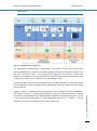

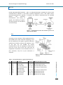


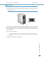


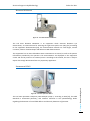


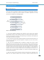


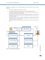
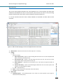


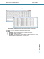
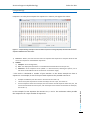


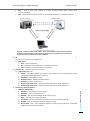
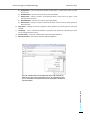
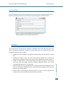
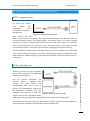


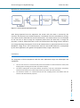

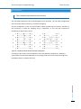


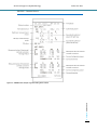
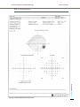
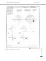


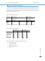

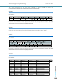


![【日本語版】CB-T1[ 263KB]](http://vs1.manualzilla.com/store/data/006617921_2-5195bfbf4019baaae295b74271f57196-150x150.png)