1
User Instructions
6350 Skyline™ Structural Steel HLL System
Reliance Industries, LLC
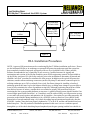
the bottom hole of the end stanchion. Only one person may be attached to any one-end stanchion at a
time.
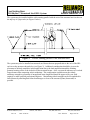
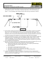
1. Identify the location where the first end stanchion (the end attachment point of the horizontal lifeline)
is to be located. Depending on the exact layout of the lifeline, it should be far enough down the beam
so as to allow for the tieback cable anchor clamp to attach to the I-beam such that it will be positioned
properly. At a minimum, the tieback distance should be equal to or greater than the stanchion height.
Contact Reliance Engineering for assistance in determining proper placement if questions remain.
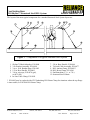
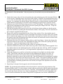
2. Widen the jaws of the 6240 I-beam clamp to slide over the I-beam flange. Position the clamp at the
right location, and tighten the clamp to the I-beam after squaring the clamp to the beam. Torque the
tightening nut of the clamp to 75- to 90 -ft. lb.
3. Slide the end stanchion tube into the receiver tube of the I-beam clamp, making sure that the anchor
lugs of the stanchion are pointing the direction that the lifeline will be going. Secure the stanchion inplace using the supplied bolt and lock nut.
4. Remove the cotter lock ring and bolt from the 5/8-in. (Note: only the 5/8-in. bow shackles may be
utilized on the tie-back assemblies because of the higher line tensions seen in the cables.) bow shackle
that is attached to the rigging screw of the tieback cable. Attach the bow shackle to the lower hole on
the opposite side of the end stanchion from where the lifeline will attach and secure the tie-back cable
in place using the bolt and cotter lock ring.
5. Widen the jaws of the 3093 Anchor Clamp to slide over the I-beam flange. Position the clamp at the
required location for the tie-back cable, and tighten the clamp to the I-beam after squaring the clamp
to the beam. Torque the tightening nut of the clamp to 40-ft. lb.
6. Adjust the rigging screw of the tie-back cable so that it is extended half way out.
7. Attach the second end of the tie-back cable to the d-ring of the Anchor clamp with the supplied 5/8-in.
bow shackle and secure the shackle bolt in place with the nut and cotter lock ring. NOTE: If using an
adjustable length tie-back cable (6077), the length should be adjusted prior to attaching to the 3093
Anchor Clamp.
8. Tighten the rigging screw until the end stanchion just begins to lean slightly towards the anchor
clamp. If the tie-back cable does not become taut after tightening the rigging screw fully, it is
permissible to loosen the 3093 Anchor Clamp and slide it along the beam away from the end
stanchion to help take up slack in the tie-back cable. Once the clamp has been repositioned, re-tighten
the clamp to the I-beam and re-tension the tie-back cable. NOTE: This method of sliding the Anchor
Clamp along the I-beam will only work for lifeline systems that are installed parallel to the I-beams;
for systems that are installed perpendicular to the I-beams, the length of the adjustable tie-back cable
must be changed.
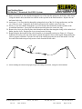
9. Repeat Steps 1 through 8 for the opposite end of the horizontal lifeline.
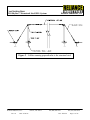
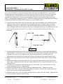
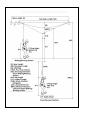
NOTE: The positioning and installation of the tie-back cables is critical to the proper function of the
horizontal lifeline system. For most systems, tie-back cable are positioned so that the angle formed by the
surface of the I-beam and the tie-back cable is 45° OR LESS. This means that the Anchor Clamp MUST
be secured to the I-beam a distance away from the end stanchion AT LEAST as far the Stanchion is tall
(for a 60-in tall End Stanchion, the Anchor Clamp MUST be tightened to the I-beam a MINIMUM of
Reliance Industries, LLC
Rev: B
Date: 07/21/04
Denver, CO 80214
Ph. (800) 488-5751
Doc.: M-6350
Fax (303) 424-8670
Page 15 of 24